flexible couplings - icpltd.co.uk · flexible couplings contents general characteristics 1 ... and...
TRANSCRIPT


Flexible Couplings
Contents
General Characteristics
1
Catalog Nº: AE / A002
Selection
Service Factors
Conventional Flexible Coupling
Special Versions
Assembly Instructions
Nomenclature used to Order Couplings
IndustrialClutch.com - No.1 International Stock Holding Distributor - Contact us for a free quotation:T: +44 (0) 1663 734 627 E: [email protected] www.IndustrialClutch.com

$
TotalOuality
Different models- Back-Pull-Out- Diesel engines- Axial displacements- Shafts with different diameters- Floating shafts
Technical InformationAvailable though our official distributors and Internet Sites.
www.gummiusa.comwww.gummi.com.arwww.gummi.com.br
- Torque limiters- Security locking- -
Conical ShaftsSpace Limited Areas
2
General Characteristics
Misalignment SolutionsMisalignment is the cause of breakage in bearings, as well as the other components of the machine (seals, gaskets, gears), which are not normally prepared for the inflection introduces to the axis. Which is primary features; elasticity, misalignment compensation, and shock absortion, the Gummi Flexible is the solution in reducing the efforts of the machines components while increasing their useful life.
Simple InstallationThe replacement is simpler and faster because it is comprised of only one rubber element. Using smaller alignment tolerances allows the element to extend the working life of its elastic center. It is not necessary to move the parts in order to replace the flexible element.
Symmetry - Security - BalanceSince the rubber element does not have any cuts in the elastic center, it there for has a guaranteed balance and no safety or security issues.
Assured qualityManufactured under the strict Quality System, and produced using only the highest quality raw materials.
Vibration and Shock Load DampeningThe ability to absorb torsional vibrations and shocks provides for an extended working life of the equipment or machine. The measurement of vibrations that are transmitted in a system, from one side to the other, it is around 70%, which is minimized with the elastic center of the coupling´s to ability to absorb the shock loads and vibrations.
EconomyThe working life capacity in the applications spare parts increases, reducing costly down time, minimizing the cost of replacement components, lubricants and inventory. The elastic center of the coupling works for a prolonged period of time without needing to be replaced.
No need to LubricateAs a result of its design and constructive characteristics, the element does not require lubrication.
IndustrialClutch.com - No.1 International Stock Holding Distributor - Contact us for a free quotation:T: +44 (0) 1663 734 627 E: [email protected] www.IndustrialClutch.com

3
Selection
- -
Power in HP, CV or KW.R.P.M
- Shaft Diameters (both driven and drive shafts)- (fs) Service Factor (according to table II < page 3>)
Data Required to Select Appropriate Coupling:
Multiply HP by the Service factor.
HP x fs , CV x 1.014 x fs or Kw x 1.36 x fs
Quick selection:
Couplings selection:
The Following Formula is used to select the appropriatecoupling
HP x fsKW x 1.36 x fs
A A A A A A A A A A A A A A A A A A A A
20 25 30 35 45 50 60 70 80 90 95 105 120 140 170 200 240 300 350 400
MODEL
RPM
10
50
100
200
300
400
500
600
700
720
800
850
900
1000
1100
1150
1200
1300
1400
1500
1600
1700
1750
1800
2000
2250
2500
2750
3000
3250
3500
3600
3750
4000
4500
5000
0.04
0.2
0.4
0.8
1.3
1.7
2.1
2.5
3.0
3.1
3.4
3.6
3.8
4.2
4.7
4.9
5.1
5.5
5.9
6.4
6.8
7.2
7.4
7.6
8.5
9.6
11
12
13
14
15
15
16
17
19
21
0.06
0.3
0.6
1.3
1.9
2.5
3.2
3.8
4.5
4.6
5.1
5.4
5.7
6.4
7.0
7.3
7.6
8.3
8.9
9.6
10
11
11
11
13
14
16
18
19
21
22
23
24
25
29
32
0.09
0.5
0.9
1.8
2.8
3.7
4.6
5.5
6.4
6.6
7.4
7.8
8.3
9.2
10
11
11
12
13
14
15
16
16
17
18
21
23
25
28
30
32
33
35
37
41
46
0.13
0.6
1.3
2.5
3.8
5.1
6.4
7.6
8.9
9.2
10
11
11
13
14
15
15
17
18
19
20
22
22
23
25
29
32
35
38
41
45
46
48
51
57
64
0.23
1.1
2.3
4.5
6.8
9
11
14
16
16
18
19
20
23
25
26
27
29
32
34
36
39
40
41
45
51
57
62
68
74
79
82
85
0.48
2.4
4.8
9.6
14
19
24
29
34
35
39
41
43
48
53
55
58
63
67
72
77
82
84
87
96
108
120
132
144
156
169
173
181
0.7
3.5
7.1
14
21
28
35
42
50
51
57
60
64
71
78
81
85
92
99
106
113
120
124
127
142
159
177
195
212
230
248
1.3
6.7
13
27
40
53
67
80
93
96
106
113
120
133
146
153
160
173
186
200
213
226
233
240
266
300
333
366
399
433
466
1.8
8.8
18
35
53
70
88
105
123
126
140
149
158
176
193
202
211
228
246
263
281
299
307
316
351
395
439
483
527
2
12
24
48
72
96
120
144
169
173
193
205
217
241
265
277
289
313
337
361
385
409
421
433
481
542
602
662
722
3
13
27
54
81
108
135
161
188
194
215
229
242
269
296
309
323
350
377
404
430
457
471
484
538
605
673
740
4
18
35
71
106
142
177
212
248
255
283
301
319
354
389
407
425
460
496
531
566
602
620
637
708
797
885
6
28
56
112
168
224
280
336
392
403
447
475
503
559
615
643
671
727
783
839
895
951
10
48
96
193
289
385
481
578
674
693
770
818
867
963
1059
1107
1156
1252
1348
1444
1541
1637
17
83
166
331
497
663
828
994
1160
1193
1325
1408
1491
1657
1823
1905
1988
2154
2320
29
143
285
571
856
1141
1427
1712
1997
2054
2283
2425
2568
2853
3139
3281
3424
3709
3995
49
244
488
976
1464
1951
2439
2927
3415
3512
3903
4147
4391
4878
5366
98
488
976
1951
2927
3903
4878
5854
6830
7025
7805
8293
8781
135
673
1345
2691
4036
5381
6726
8072
9417
9686
10762
11435
12108
191
956
1912
3823
5735
7647
9559
11470
13382
13764
15294
16250
17205
Table I Maximum air Temperature: 176 F (80 C)
The information in the catalog is subject to modifications without warning
Once the value is obtained from the formula, go to Table I below, and read down on the RPM column until the RPM for the case engine is found. Read across until the closest number to the result obtained from the formula is found. Then read up to the top of the chart to find the recommended coupling.
Example A :
Generator driven by a Diesel Engine (370 HP & 1000 RPM)
HP x Fs = 370 x 2.5 = 925
Look up under the RPM column in Table I below until you reach 1000 RPM. Then move to the right until you find the closest value to the calculated 925 (in this case it would be 950). Move up to the top line on the chart and you will read <> A 140, which is the recommended coupling size for this application.
Nominal H.P.All the reading between that fall below the heavy black line correspond to Flexible Couplings models with hubs that are fitted on the flanges and dynamically balanced.
IndustrialClutch.com - No.1 International Stock Holding Distributor - Contact us for a free quotation:T: +44 (0) 1663 734 627 E: [email protected] www.IndustrialClutch.com

GENERAL INDUSTRY
AGITATORSVertical and HorizontalScrew Propeller, PaddleGARGE HAUL PULLERBLOWERSCentrifugalLobe or VaneCAR DUMPERSCAR PULLERSCLARIFIER OR CLASSIFIERCOMPRESSORSCentrifugalRotary, Lobe or VaneRotary, ScrewReciprocating Direct Connected Refer to factory Without Flywhees Refer to factory With Flyweel and Gear between Compressor and Prime Mover 1 cylinder, single acting 1 cylinder, double acting 2 cylinders, single acting 2 cylinders, double acting 3 cylinder, single acting 3 cylinder, double acting 4 cylinders, single acting 4 cylinders, double actingCONVERYORSApron, Assembly, Belt, Chain
1.002.00
1.001.252.501.501.00
1.002.001.75
4.003.503.503.003.002.001.751.75
GENERATORSEven LoadHoist or Railway ServiceWelder LoadHAMMERMILLLAUNDRY WASHER OR TUMBLERLINE SHAFTSAny Processing MachineryMACHINE TOOLSAuxiliary DriveBending Roll, Notching Press,Punch Press, Planer, Plate ReversingMain DriveTraverse DriveMAN LIFTSMETAL FORMING MACHINESDraw Brench Carriage andMain DriveExtruderForming Machine and Forming MillsSlittersWire Drawing or FlatteningWire WinderCorlers and UncorlersMIXERS (see Agitators)ConcreteMullerPRESS, PRINTINPUG MILLPULVERIZERSHammermill
1.001.502.001.752.00
1.50
1.00
1.751.501.00
2.002.002.001.002.001.501.50
1.751.501.501.75
1.75
HogRollerPUMPSCentrifugal Constant speed Frequent speed changers under loadDescaling, with accumulatorsGear, Rotary, or VaneReciprocating 1 cylinder, single acting 1 cylinder, double acting 2 cylinders, single acting 2 cylinders, double acting 3 or more cylindersSCRENSAir WashingGrizzlyRotary Coal or SandVibratingWaterSTEERING GEARSTOKERTUMBLING BARRELWINCH, MANEUVERINGDredge, MarineWINDLASSWOODWORKING MACHINERY
2.001.50
1.001.251.501.50
2.502.002.001.751.50
1.002.001.502.501.001.001.001.75
1.501.501.00
APPLICATION BY INDUSTRY
AGGREGATE PROCESSING,CEMENT, MINING KILNS, TUBE,ROD AND BALL MILLSDirector or on L.S. schaft ofReducer, with final drive:Machined Spur GearsSingle Helical or Herringbone GearsConveyors, Feeders, Screens,Elevators See General ListingCrushers, Ore or StoneDryer, RotaryGrizzlyHammermill or HogTumbling Mill or BarrelBREWING AND DISTILLINGBottle and Can Filling MachinesBrew KettleCookers, Continuous DutyLauter TubMash TubScale Hopper, Frequent PeaksCLAY WORKING INDUSTRYBrick Press, Briquette Machine,Clay Working Machine, Pug MillDREGESCable ReelConveyorsCutter Head, Jig DriveManeuvering WinchPumps (uniform load)Screen Drive, StackerUtility Winch FOOD INDUSTRYBeet SlicerBottling, Can Filling MachineCereal CookerDough Mixer, Meat GrinderLUMBERBand ResawCircular Resaw, Cut offEdger, Head Rig, HogGrang Saw
2.502.001.00
2.501.752.001.751.75
1.001.001.251.501.251.75
1.75
1.751.502.001.501.501.751.50
1.751.001.251.75
1.501.752.00
Kickout Piercer Reeler Thrust Black Tube Conveyor RollsSideguardsSkelp Mills Refer to factorySlitters, Steel Mill onlySoaking Pit Cover Drives Lift TravelStraightenersUnscrammblers (Billet Bundle Busters)Wire Drawing MachineryOIL INDUSTRYChillerOilwell Pumping (not over 150% peak torque)Paraffin Filter PressRotary KilnPAPAR MILLSBarker Auxiliary, HydraulicBarker, MechanicalBarking Drum L.S. shaft of reducer with final drive - Helical or Herringbone Gear Machined Spur Gear Cast Tooth Spur GearBeater & PilperBleachers, CoatersCalender & Super CalenderChipperConverting MachineCouchCutter, Felt WhipperCylinder, DryerFelt StrtcherFourdrinierJordanLog HaulLine ShaftPress
2.003.002.502.502.002.00
1.75
1.502.502.002.002.00
1.252.001.502.00
2.252.25
2.002.503.001.751.002.003.001.501.752.001.751.251.752.002.001.502.00
Pulp GrinderReel, Rwinder, WinderStock Chest, Washer, ThickenerSuction RollRUBBER INDUSTRYCalenderCraker, PlasticatorExtruderIntensive or Banbury MixerMixing Mill, Refiner or Sheeter One or two in line Three or four in line Five or more in lineTire Building MachineTire & Tube Press Opener (Peak Torque)Tuber, Strainer, PelletizerWarming Mill Oner or two Mills in line Three or more Mills in lineWasherSEWAGE DISPOSAL EQUIPMENTBar Screen, Chemical Feeders, Collectors, Dewatering Screen, Grit CollectorSUGAR INDUSTRYCane Carrier & LevelerCane Knife & CrusherMill Stands, Turbine Driven with all helical or herringbone gearsElectric Drive or Steam Engine Drive with Helical Herringbone, or Spur Gears with any Prime MoverTEXTILE INDUSTRYBatcherCalender, Card MachineCloth Finishing MachineDry Can, LoomDyeing MachineryKnitting Machine Refer to factoryMangle, Napper, SoaperSpinner, Tenter Frame, Winder
2.001.501.501.75
2.002.501.752.50
2.502.001.752.501.001.75
2.001.752.50
1.00
1.752.00
1.50
1.75
1.251.501.501.501.25
1.251.50
Service factors listed are typical values based on normal operation of the drive systems.
24
Service Factors
Flight, ScrewBucketLive Roll, Shaker andReciprocatingCRANES AND HOISTMain HoistSkip HoistSlopeBridge, Travel or TrolleyDYNAMOMETER ELEVATORSBucket, Centrifugal DischargeFreightGravity DischargePassengerESCALATORSEXCITER, GENERATOREXTRUDER, PLASTICFANSCentrifugalCooling TowerForced Draft - Across the Line startForced Draft Motor Driven thru fluid or electric slip clutchGas RecirculatingInduced Draft with damper control or blade cleanerIndiced Draft without controlsFEEDERSApron, Belt, Disc, ScrewReprocating
1.001.25
3.00
2.001.751.501.75
2.00
1.25
1.001.001.50
1.002.001.50
1.001.50
1.252.00
1.002.50
(Reciproacting) Refer to FactoryLog HaulPlanerRolls, Non-ReversingRolls, ReversingSawdust ConveyorSlab ConveyorSorting TableTrimmerMETAL ROLLING MILL AUXILIARIESCoilers (up or down) Cold Mills onlyCoilers (up or down) Hot Mills onlyCoke Plants Door Opener Pusher or Larry Car Traction Drive Pusher Ram DriveCold Mills Strip Mills Refer to factoryTemper Refer to factoryCooling BedsDrawbenchFeed Rolls - Blooming MillFurnace PushersHot and Cold SawsHot Mills Edger Drivers Refer to factory Reversing Blooming or Slabbing Mills Refer to factory Strip or Sheet Mills Refer to factoryIngot CarsManipulatorsMerchant Mills Refer to factoryMill Tables Hot Bed or Transfer non-reversing Roughing Breakdown Mills Runout, non-reversing, non-plugging Runuot, reversingReel DrivesRod Mills Refer to factoryScrewdownSeamless Tube Mills
2.001.751.502.001.251.751.501.75
1.502.00
2.00
3.502.50
1.502.003.502.002.00
2.503.50
2.004.002.504.001.75
1.50
TABLE II AFor motor drives through a gear reducer with both high speed and low speed shafts connected with a resilient coupling, it is possible to use a lower service factor on the high speed coupling as follows:
When LSSService Factor
HSS ServiceFactor is:
1.0 thru 1.51.75
2.0 or more
1.01.25
Same as LSS
TABLE II BService factors for engine drives are those required for applications where good flywheel regulation prevents torque fluctuations greater then 20%. For drives where torque fluctuations are greater ro where the operation is near a serious critical or torsional vibration, mass elastic study is necesary.
To use Table II B, fisrt determine application service factro from Table II Use the fastor to determine ENGINE Service Factor from Table II B When service factor from Table II is greater than 2.0, refer complete application details to the Factory for engineering review.
N° of Cylinders 4 or 5 6 or more
Table II Service Factor
Engine Service Factor
1.0
2.0
1.25
2.25
1.5
2.5
1.75
2.75
2.0
3.0
1.0
1.5
1.25
1.75
1.5
2.0
1.75
2.25
2.0
2.5
Engine Drive Service Factor
For motor driven reducers with resilient high speed and low speed shaft coupling, refer to Table II A. For motors with brakes, select the coupling based on the higher of the two torque ratings.For balanced opposed design, divide number of cylinders by two and use abova table for reciprocating compresors.
Table II
IndustrialClutch.com - No.1 International Stock Holding Distributor - Contact us for a free quotation:T: +44 (0) 1663 734 627 E: [email protected] www.IndustrialClutch.com

Conventional Flexible Couplings Model
5
I J
H A B D C
G
EFThe Conventional Flexile Coupling model applications are indicated in Fig. 1and Fig. 2 above. The Hub selection and type is dependent upon the shaft diameter.
With 2 conventional hubsFig. 1
Fig. 2With 1 conventional hub and 1 integral hub
NORMAL HUB
A-20
A-25
A-30
A-35
A-45
A-50
A-60
A-70
A-80
A-90
A-95
A-105
A-120/90
A-120/120
A-140/100
A-140/140
A-170/70
A-170/130
A-170/170
A-200/90
A-200/140
A-200/200
A-240/150
A-240/200
A-240/240
A-300/150
A-300/200
A300/250
A-300/300
A-350/200
A-350/250
A350/350
A-400/250
A-400/400
MODELNOMINALTORQUE
Lb.in
TORSION(º)
weight(Lb.)
Gd2(Lb + ft²)
A B C D E F G H I J
260
390
564
781
1302
2256
3906
6770
8072
9200
11717
27775
34284
59020
101550
174892
299007
598015
2º
5º
2º
4º
3º
6º
5º
9º
5º
6º
4º
8º
5º
9º
7º
11º
4º
10º
6º
10º
1.94
1.94
4.52
4.52
8.90
8.90
21.54
21.54
47.97
47.97
63.12
63.23
125.95
175.90
126.95
177.90
271.80
357.14
500.00
317.46
343.25
547.62
678.58
803.57
1382.00
674.61
799.60
1180.57
1507.00
0.02
0.02
0.07
0.07
0.34
0.34
1.60
1.60
4.20
4.20
7.20
7.20
40.50
40.50
95.00
95.00
415.00
415.00
INTEGRAL HUB
Max Min Max
2
2
3
3
5
5
6
6
8
8
9
9
11
11
17
17
21
21
2932/
2932/
2536/
2536/
2132/
2132/
1932/
1932/
14/
14/
1116/
1116/
532/
532/
116/
116/
1
1
1
1
2
2
3
3
4
4
5
5
5
7
5
7
5
9
10
7
7
10
8
11
15
8
11
10
1332/
1516/
1516/
916/
1116/
1116/
932/
1
1
1
1
2
2
2
3
3
3
3
4
3
5
2
5
6
3
5
7
5
7
9
5
7
9
11
2932/
14/
1
1
1
1
1
1
1
1
1
1
1
3
5
2
4
5
4
5
5
4
5
5
1
1
1
1
1
1
2
2
3
3
3
3
4
4
4
4
7
7
9
9
1
1
1
1
2
2
3
3
3
3
3
3
5
5
3
5
7
3
5
7
7
7
2
2
3
3
4
4
6
6
8
8
9
9
13
13
17
19
23
27
3
3
4
7
6
6
8
8
11
11
12
12
15
15
21
21
29
29
1
1
1
1
2
2
4
4
4
4
5
5
7
10
1332/
1516/
34/
34/
1516/
916/
716/
716/
2932/
2932/
2932/
78/
1716/
78/
2164/
78/
716/
38/
78/
716/
78/
2532/
916/
1164/
316/
1316/
916/
6164/
1132/
1516/
3164/
3164/
4764/
12/
1516/
18/
34/
1116/
12/
78/
3564/
2932/
716/
78/
2932/
78/
1316/
716/
716/
716/
716/
58/
58/
732/
732/
732/
732/
1316/
1316/
1316/
1316/
12/
34/
12/
12/
34/
12/
38/
18/
34/
18/
3532/
1916/
316/
316/
916/
916/
3132/
3132/
916/
916/
916/
916/
916/
916/
2332/
2332/
2332/
2332/
932/
932/
932/
932/
6364/
38/
38/
6364/
34/
34/
38/
38/
18/
18/
18/
18/
1516/
1516/
18/
18/
532/
78/
232/
1516/
18/
332/
516/
232/
1116/
1116/
58/
58/
78/
78/
12/
12/
14/
14/
2732/
2732/
12/
1332/
1532/
1332/
34/
34/
1516/
1516/
12/
12/
2132/
2132/
1316/
1316/
316/
316/
34/
34/
2132/
2132/
18/
18/
12/
12/
2332/
2332/
3132/
3132/
12/
2332/
2332/
1316/
1316/
18/
18/
2
2
3
3
4
4
5
5
7
7
7
7
10
15
1932/
1932/
38/
38/
1132/
1132/
2932/
2932/
332/
332/
18/
5164/
5164/
5164/
5164/
Table III
The information displayed in this catalog is subject to modifications without warning.
IndustrialClutch.com - No.1 International Stock Holding Distributor - Contact us for a free quotation:T: +44 (0) 1663 734 627 E: [email protected] www.IndustrialClutch.com

Special hub (CX)
Assembly on steering wheels (CC, CF)
High speeds (CE)
For points of conical Shafts (EC)
AXIAL HUB (CX)This model has been developed for applications that do not allowfor axial displacement due to their construction characteristics.Use indicated hubs for machines with sliding shafts. When makingthe request, indicate the maximum displacement.
For assembly on steering wheels,use type reel (CC), or typebridle (CF).
Mill engine
MODEL
A-20/25
A-30/35
A-45/50
A-60/70
A-80/90
A-95/105
A-120/140
A-170/200
A-240/300
A-350/400
3
4
7
10
13
MODELØ Max. Ø Max.
(CC)(CF)
26
Special Versions
Speeds that fall outside of the speed parameters in Table I, the connections must be dynamically balanced and used with fitted hubs. When making this request, please indicate the rotating speed (RPM)
1
1
2
2
2932/
316/
916/
38/
4164/
2132/
38/
332/
IndustrialClutch.com - No.1 International Stock Holding Distributor - Contact us for a free quotation:T: +44 (0) 1663 734 627 E: [email protected] www.IndustrialClutch.com

Special Versions
7
Floating Shafts (EF)
With spacer (ES)
Torque limiting (LT)
With security ties (BS)
Specially designed to be used in applicationswithin a cooling tower. For this request, pleaseindicate the distances between shaft points.
All the different coupilng version can beoutfitted with a spacer, which facilitates thedisassembling, which is common in pumpapplications (Back´pull-out). For this request,please indicate the distances between theshaft points.
For applications where it is crucial to avoidtransmission overloads.
Where the transmission mustcontinue working and functioning,regardless of overloads or apossible breakage within theelastic center of the coupling.
L
L
IndustrialClutch.com - No.1 International Stock Holding Distributor - Contact us for a free quotation:T: +44 (0) 1663 734 627 E: [email protected] www.IndustrialClutch.com

Aggressive Environments (RE)Steam
Acids
Bases
Oils
Ethylene Glicol
Weather inclemency
Low Regular High
28
Taper Lock Bushings
The electrometric rubber used in Gummi´s coupling generally providefor a good resistance to chemical products or aggresive agents. In such cases in which a constant highly aggresive contact is encountered, the use of a special coating on the rubber element is recommended.When ordering, please indicated which agents may be in encountered,and on what basis.
HF HH FF
B
DA
E
CGummi A-20 thru A-95 TLB
Gummi A-105 thru A-300 TLB
B
D A
EC
Taper Lock Bushings which are packed separately, come in a wide range of bore sizes. Please specify required Coupling Size along with proper nomenclature when ordering. A complete coupling consists of two (2) hub assemblies and one (1) rubber element.
Cplg
SIZE
5000
5000
4000
4000
3000
3000
2500
2500
2250
2250
1600
1600
1200
1200
900
900
700
700
2.73
2.60
5.69
5.56
10.47
9.99
23.55
26.79
56.00
56.00
69.27
56.50
122.02
117.35
280.18
297.20
654.33
682.28
1008
1108
1008
1108
1310
1610
2012
2517
2517
2517
3020
3535
4040
4545
4545
5050
7060
8065
.2
.2
.2
.2
.6
.7
1.4
2.8
2.8
2.8
5.2
11.5
17.5
22.4
22.4
28.0
76.0
99.0
0721
0722
0723
0724
0725
0726
0727
0728
0729
0731
0731
0732
0733
0735
0737
0740
0741
0742
0751
0752
0753
0754
0755
0756
0757
0758
0759
0759
0761
0762
0763
0765
0767
0770
0771
0772
.99
.93
1.94
1.87
3.79
3.55
8.38
9.90
17.53
17.53
22.22
15.94
39.29
36.73
89.09
95.83
228.53
254.57
0001
0002
0003
0004
0005
0006
0007
0008
0009
0010
0011
0012
0013
0014
0015
0016
0017
0018
.66
.66
1.43
1.43
2.38
2.38
5.76
5.76
18.85
18.85
22.16
22.27
40.01
40.45
94.58
98.10
179.01
192.68
6
6
8
8
10
10
12
12
10
10
12
12
10
10
12
12
30
30
A- 20
A- 25
A- 30
A- 35
A- 45
A- 50
A- 60
A- 70
A- 80
A- 90
A- 95
A- 105
A- 120
A- 140
A- 170
A- 200
A- 240
A- 300
A B C DMin. Max.
Bore Rangeof Bush
Max.
Ppm
Wt (Lb)Cplg.W/O
bush
BushingsItems required for complete CPLG
Hub Assy (2) Req d' Flexible Element
Main dimensions (in)
E
Screw sizenr. screwPer hubNr. Wt Type H Type F Wt Nr. Wt
-20 x 1
-20 x 1
-18 x 1
-18 x 1
-18 x 1
-18 x 1
-16 x 1
-16 x 2
-13 x 2
-13 x 2
-13 x 2
-13 x 1
-11 x 2
-11 x 2
-10 x 2
-10 x 2
-10 x 3
-10 x 3
14/
516/
38/
12/
58/
34/
18/
14/
516/
516/
516/
38/
12/
12/
12/
58/
34/
34/
34/
18/
12/
14/
14/
12/
34/
14/
14/
34/
34/
12/
12/
1
1
1
1
2
4
5
12/
12/
12/
12/
12/
12/
12/
12/
12/
12/
78/
316/
716/
1516/
1516/
716/
1516/
716/
1
1
1
1
1
1
2
2
2
2
3
3
4
4
4
5
7
8
38/
1516/
1516/
1516/
716/
12/
12/
12/
58/
18/
18/
2
2
3
3
5
5
6
6
8
8
9
9
11
11
17
17
21
21
2932/
2532/
2132/
1932/
14/
1116/
532/
116/
116/
532/
1116/
14/
1932/
2132/
2532/
2932/1
1
1
1
1
1
2
2
3
3
3
3
4
4
7
7
9
9
316/
3132/
2332/
932/
932/
932/
932/
2332/
916/
916/
916/
916/
3132/
916/
916/
316/2
2
3
3
3
3
5
6
7
7
7
10
12
13
16
17
21
22
1516/
3132/
116/
364/
3564/
4764/
2332/
932/
1964/
1964/
932/
3564/
364/
116/
1516/
1516/
3132/
516/
3
3
4
4
6
6
8
8
11
11
12
12
15
15
21
21
29
29
316/
316/
1516/
34/
12/
2132/
1316/
34/
2132/
18/
18/
2132/
34/
1316/
34/
1516/
12/
2132/
TECHNICAL DATA FOR TAPER-LOCK BUSHING COUPLINGS
Ordering example: to order an A-70 TLB HH coupling, specify: Two (2) taper-lock aassemblies HH and one (1) flexible element
Table IV
The information displayed in this catalog is subject to modifications without warning.
IndustrialClutch.com - No.1 International Stock Holding Distributor - Contact us for a free quotation:T: +44 (0) 1663 734 627 E: [email protected] www.IndustrialClutch.com

Assembly Instructions
9
Example of adjustment of the Elastic Center
Incorrect Adjustment or Tightening Procedure
Correct Adjustment and Tightening Procedure
E R
Distance between hubs.
Angular.
Radial.
Aº
- First Adjustment in the shape of a cross. - Second Adjustment in a circular motion as indicated.
The Values "A" and "R" are the maximum tolerances allowable.
MODEL A(º)
R(”)
E(”)
tol(”)
A20 / 25A30 / 35A45 / 50A60 / 70A80 / 90A95 / 105A120 / 140A170 / 200A240 / 300A350 / 400
0.511.511.51.52344
Table V
TORQUE (Lbs ft)
crossTightening
circular
1-3/161-9/161-31/322-9/163-9/163-9/164-23/327-9/329-9/3213-3/16
1/641/643/643/645/645/645/325/323/163/16
0.011/641/641/323/643/645/641/81/81/8
3.65.47.2
14.536.036.043.472.3
108.5130.0
3.67.2
14.521.743.443.450.6
108.5159.0180.0
In the initial assembly, the shafts must be aligned. Leave a gap between the inner flanges of both hubs, this distance is indicate as "C" in Table IV .
Leave a gap between the inner flanges of the hub faces as indicated in the drawing to the right.
It the bolts are over tightened as shown in the figure to the right, the compressed rubber element will shear during operations. If the bolts are not tightened correctly, start up toque will detach the inner flange.
For a precise tightening adjustment, we recommend that you use an Impact Wrench with and air pressure gauge, which will allow for the tightening according to the air pressure torque values indicated in Table V above. For the adjustment of taper lock hubs and or flywheels, use only and Impact Wrench.
If an impact wrench is not available, use a plain wrench and proceed as follows:1- Tighten until the washer is flattened.2- Tighten bolts 1 ½ turns after washer is flattened.
IndustrialClutch.com - No.1 International Stock Holding Distributor - Contact us for a free quotation:T: +44 (0) 1663 734 627 E: [email protected] www.IndustrialClutch.com

When ordering a Gummi Flexible Coupling, the following information must be provided.
Connection model A 105 with two integral hubs and one spacer L=10 inch.
1- MODEL
According to the selection (Tables I and II)
2- TYPE OF CUBE
Advise the selected type of hub
Without indication - Two conventional blank bore hubs will be provided
A conventional hub and a integral hub
Two integral hubs
Axial hub
Reel
Bridle plate
Fitted hubs
Conventional hub for point of conical shafts
Integral hub for point of conic shafts
3- TYPE OF ASSEMBLY
Floating shafts
Spacer
Torque limiting
Security ties
Special covering
Taper lock Bushing
4- ADDITIONAL INFORMATION
Indicate the critical dimensions
CICI / CICXCCCFCEECECI
EFESLTBSRETLB
1- Model
2- Type of cube
3- Type of assembly
4- Additional information
A 105 - CI / CI - ES - 10”
The information displayed in this catalog is subject to modifications without Warning.
210
Nomenclature used to Request a Couplings
IndustrialClutch.com - No.1 International Stock Holding Distributor - Contact us for a free quotation:T: +44 (0) 1663 734 627 E: [email protected] www.IndustrialClutch.com
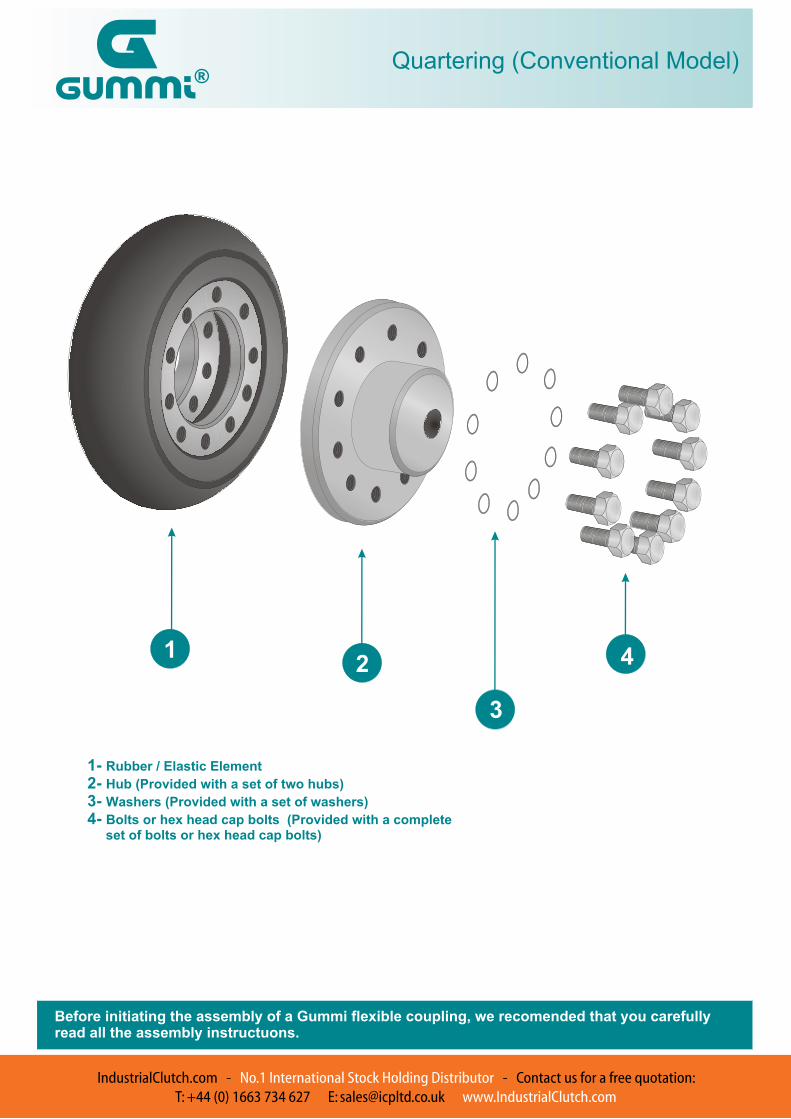
Quartering (Conventional Model)
11
12
3
4
1- Rubber / Elastic Element
2- Hub (Provided with a set of two hubs)
3- Washers (Provided with a set of washers)
4- Bolts or hex head cap bolts (Provided with a complete set of bolts or hex head cap bolts)
Before initiating the assembly of a Gummi flexible coupling, we recomended that you carefullyread all the assembly instructuons.
IndustrialClutch.com - No.1 International Stock Holding Distributor - Contact us for a free quotation:T: +44 (0) 1663 734 627 E: [email protected] www.IndustrialClutch.com
