flexible air interface for scalable service delivery
TRANSCRIPT

Call: H2020-ICT-2014-2
Project reference: 671660
Project Name:
Flexible Air iNTerfAce for Scalable service delivery wiThin wIreless Communication networks of the 5th Generation (FANTASTIC-5G)
Deliverable D5.3
Integrated platforms and evaluation results
Date of delivery: 30/06/2017 Version: 1
Start date of project: 01/07/2015 Duration: 24 months

Document properties:
Document Number: D5.3
Document Title: Integrated platforms and evaluation results
Editor(s): Musbah Shaat (CTTC)
Authors: Amer Baghdadi (TB), Charbel Abdel Nour (TB), Jeremy Nadal (TB), Jean-Baptiste Doré (CEA), Dimitri Kténas (CEA), Marc Laugeois (CEA), Musbah Shaat (CTTC), Pol Henarejos (CTTC), Javier Arribas (CTTC), Dennis Wieruch (HHI), Johannes Dommel (HHI), Thomas Wirth (HHI), Sameh Eldessoki (HHI), Qi Wang (HWDU), Johannes Koppenborg (NOKIA).
Contractual Date of Delivery: 30/06/2017
Dissemination level: PU1
Status: Final
Version: 1
File Name: FANTASTIC-5G D5.3_v1
Abstract
The proof-of-concepts (PoCs) of FANTASTIC-5G aim at demonstrating the feasibility and the
superiority of selected FANTASTIC-5G air interface technologies. This third and last deliverable of
WP5 (D5.3) presents the integration of the developed PoC components into the final PoC platforms. It
describes the integrated platforms, the evaluation results and the final measurements. To that end, the
deliverable starts by briefly revising part of the scenarios and main PoC building components provided
in the previous two deliverables (D5.1 and D5.2) in order to provide a complete picture of the integrated
platforms. Then, the deliverable presents the evaluation results and the main outcomes of the different
PoCs. The different PoCs are classified and presented in three main categories: (1) Prototyping for
post-OFDM waveforms, (2) Evaluation of waveform coexistence aspects, and (3) Development of an
SDR-based demonstration for broadcast and multicast transmission.
Keywords
5G, proof-of-concept, post-OFDM, waveform, performance metrics, scenarios, vehicular
communications, massive machine communications, mission critical communications, hardware
complexity, error rate, latency, power consumption, transceiver algorithm, FBMC, BF-OFDM, FC-
ODM, CP-OFDM, UF-OFDM, P-OFDM, software programmable hardware, software defined radio,
MIMO, hardware-in-the-loop, broadcast and multicast.
1 CO = Confidential, only members of the consortium (including the Commission Services)
PU = Public

FANTASTIC-5G Deliverable D5.3
Dissemination level: Public Page 3 / 69
Executive Summary
Work-Package (WP) 5 in FANTASTIC-5G is dealing with the Proof-of-concept (PoC) activities
that aim at validating the feasibility and the superiority of part of the solutions provided by the
foreseen 5G air interface. The work carried out in this WP is reported in three deliverables. The
first deliverable (D5.1) was dedicated to provide the necessary information regarding the
techniques selection in addition to the scenarios identification. The second deliverable (D5.2)
presented the implementation of the components for the different PoC along with the associated
results and intermediate version setup and outcomes.
In this third deliverable of WP5, the final integrated platforms are presented along with the
performance evaluation results. For the sake of having a self-contained document, scenarios and
basic components and building blocks of the different PoCs already detailed in the
aforementioned two deliverables are briefly reviewed. The proposed implementations are
grouped and presented in three main categories: (1) Prototyping for post-Orthogonal Frequency
Division Multiplexing (OFDM) waveforms, (2) Evaluation of waveform coexistence aspects, and
(3) Development of a Software Defined Radio (SDR)-based demonstration for broadcast and
multicast transmission.
In this context, Filter Bank Multi-Carrier (FBMC), Flexible Configured (FC)-OFDM, and
Universal-Filtered (UF)-OFDM low-complexity transceivers have been implemented in a real-
time hardware PoC platform. These promising candidate waveforms have been evaluated and
outstanding results, with respect to state-of-the-art Cyclic Prefix (CP)-OFDM, are demonstrated
through implementation and support of Massive Machine Communication (MMC), vehicle-to-
everything (V2X) and Machine Critical Communications (MCC) scenarios. Impressive results,
compared to CP-OFDM, are illustrated in terms of robustness against synchronization errors and
Doppler effects and in terms of suitability for low latency and reliable communications.
To overcome the difficulties of adapting the FBMC waveform to multiple antenna schemes,
Block Filtered (BF)-OFDM that combines CP-OFDM and filter bank as in FBMC is
implemented. Accordingly, 2x2 Multiple-Input Multiple-Output (MIMO) BF-OFDM based
transceiver is implemented. The PoC demonstrated the compatibility of BF-OFDM with MIMO
and confirms that BF-OFDM has good frequency localization properties with a very steep inband
and out-of-band roll-offs that enable its coexistence with legacy Long Time Evolution (LTE) and
other waveforms in adjacent bands.
Pulse shape adaptation for the asynchronous Timing Adjustment (TA)-free uplink low latency
transmission is considered by the implementation of Pulse shaped (P)-OFDM waveform. The
implementation is realized using Universal Software Radio Peripheral (USRP) nodes. In
comparison with CP-OFDM and considering a strong-interference limited uplink scenario, P-
OFDM achieves promising results and exhibits robustness against the interferer where CP-OFDM
is subject to severe link degradation. Additionally, single link real-time evaluation is performed
in the public streets considering both Line-Of-Sight (LOS) and Non-Line-Of-Sight (NLOS). It
shows that P-OFDM outperforms CP-OFDM attributed to the capability of Inter-Carrier-
Interference (ICI) mitigation by low-out-of-band-leakage pulse-shaping filter as well as better
collection of the receive energy with the matched filter at the receiver. Additionally, single link
real-time evaluation for a high velocity scenario is also performed within an indoor test bed and
a channel emulator.
Towards fulfilling the low latency transmission requirements of MCC services, a parameterized-
OFDM transceiver has been developed and implemented on a Digital Signal Processor (DSP)-
based SDR platform. In the proposed implementation, the radio frame structure is scalable with
respect to its time properties and can achieve end-to-end latencies below 1 ms.

FANTASTIC-5G Deliverable D5.3
Dissemination level: Public Page 4 / 69
Considering the evaluation of waveform coexistence aspects between different waveforms in
adjacent bands, the coexistence aspects for CP-OFDM, UF-OFDM and FBMC/OQAM
waveforms are demonstrated with realistic hardware impairments. The performance is measured
in terms of error-vector magnitude (EVM). Different settings of time delay and guard carriers
between the user of interest and the asynchronous interferers are considered.
The joint broadcast and multicast transmission PoC is implemented by means of Software Defined
Radio (SDR). Techniques under investigation are the non-orthogonal beam superposition and
joint decoding techniques. A hardware/software environment based on USRP nodes for User
Equipment (UE) and evolved Node B (eNB) is developed. All the signal processing blocks are
implemented in software with all the necessary optimizations to reduce the implementation
complexity. Real time evaluation is performed to demonstrate the scheme ability to use the entire
available bandwidth to transmit several multimedia streams sharing the same frequency and time
resources, and to use the spatial dimension to design the coverage of each stream, distinguishing
between broadcast and multicast transmissions. Additionally, performance evaluation with
different emulated channels are performed and compared with LTE as benchmark.
Finally, it is worth mentioning that the aforementioned PoCs have been presented in several
dissemination events such as EuCNC 2016, ETSI Workshop 2016, ISTC 2016, 2nd Global 5G
Event 2016, MWC 2017, ICC 2017, and EuCNC 2017.

FANTASTIC-5G Deliverable D5.3
Dissemination level: Public Page 5 / 69
Table of Contents
List of Figures .............................................................................................................................. 7
List of Tables ............................................................................................................................. 10
List of Acronyms and Abbreviations ....................................................................................... 11
1 Introduction......................................................................................................................... 14 1.1 Objective of the document ........................................................................................... 14
1.2 Structure of the document ............................................................................................ 14
2 Post-OFDM waveform prototyping PoC .......................................................................... 14 2.1 Flexible PoC for Post-OFDM waveforms ................................................................... 14
2.1.1 UF-OFDM: implementation of PoC components and algorithm/architecture
optimizations .......................................................................................................... 15
2.1.2 FC-OFDM: implementation of PoC components and algorithm/architecture
optimizations .......................................................................................................... 16
2.1.3 FBMC: implementation of PoC components and algorithm/architecture
optimizations .......................................................................................................... 17
2.1.4 PoC final version and evaluation results................................................................. 18
2.1.4.1 Massive machine communication scenario results ............................................ 19
2.1.4.2 Vehicular communication scenario results ........................................................ 22
2.1.4.3 Mission Critical Communication scenario results ............................................. 23
2.2 FBMC-MIMO transceiver based on software programmable hardware ..................... 25
2.2.1 Implementation of PoC components and algorithm/architecture optimizations ..... 25
2.2.1.1 Key building blocks description ........................................................................ 26
2.2.2 PoC final version and evaluation results................................................................. 30
2.2.2.1 Complexity assessment ..................................................................................... 30
2.2.2.2 KPI ..................................................................................................................... 34
2.2.2.3 Demonstrations .................................................................................................. 35
2.3 Pulse shaped OFDM for TA-free low latency transmission ........................................ 37
2.3.1 Asynchronous transmission using P-OFDM waveform ......................................... 37
2.3.1.1 Evaluation scenario ........................................................................................... 37
2.3.1.2 Results ............................................................................................................... 37
2.3.2 Single link real time evaluation in high velocity scenario ...................................... 39
2.4 Post- and Parameterized-OFDM waveforms for low latency transmission ................. 43
2.4.1 Implementation of PoC components and algorithm/architecture optimizations ..... 43
2.4.2 PoC final version and evaluation results................................................................. 44
3 Coexistence aspects evaluation PoC .................................................................................. 46 3.1 Implementation of PoC components and algorithm/architecture optimizations .......... 46
3.1.1 Overview of Waveform Candidates ....................................................................... 47
3.1.2 Cross-band Multiple Access Interference ............................................................... 48
3.1.3 Evaluation Setup ..................................................................................................... 48
3.2 PoC final version and evaluation results ...................................................................... 50
4 Broadcast and multicast SDR-based PoC ........................................................................ 53 4.1 Implementation of PoC components and algorithm/architecture optimizations .......... 53
4.2 PoC final version and evaluation results ...................................................................... 56
4.2.1 Real-time performance ........................................................................................... 56
4.2.2 Emulated performance ............................................................................................ 57
4.2.2.1 Details of channel emulation ............................................................................. 58
4.2.2.2 Emulation results ............................................................................................... 58
4.2.2.3 LTE benchmark ................................................................................................. 63
5 Conclusions .......................................................................................................................... 67

FANTASTIC-5G Deliverable D5.3
Dissemination level: Public Page 6 / 69
6 References ............................................................................................................................ 68

FANTASTIC-5G Deliverable D5.3
Dissemination level: Public Page 7 / 69
List of Figures
Figure 2-1: Hardware architecture of the proposed UF-OFDM transmitter. .............................. 16
Figure 2-2: Hardware architecture of the UF-OFDM receiver. .................................................. 16
Figure 2-3: Hardware architecture of the FC-OFDM receiver. ................................................... 17
Figure 2-4: Low-complexity FBMC/OQAM transmitter hardware architecture. ....................... 17
Figure 2-5: FS implementation of the FBMC/OQAM receiver. ................................................. 18
Figure 2-6: Flexible PoC for Post-OFDM waveforms. ............................................................... 19
Figure 2-7: Flexible PoC for Post-OFDM waveforms at the 2nd Global 5G Event. .................. 20
Figure 2-8: Flexible PoC for Post-OFDM waveforms at the EuCNC’17. .................................. 20
Figure 2-9: Obtained results on the PoC platform for MMC scenario. ....................................... 21
Figure 2-10: Obtained results on the PoC platform for V2X scenario. ....................................... 23
Figure 2-11: Obtained results on the PoC platform for MCC scenario. ...................................... 24
Figure 2-12: Frame format for antenna 0. A small set of RB is depicted. .................................. 26
Figure 2-13 : Architecture of the BF-OFDM transmitter. Blue boxes are for the logic while green
are for the memories. ................................................................................................................... 27
Figure 2-14: BF-OFDM buffer mapping. ................................................................................... 27
Figure 2-15: Architecture of the channel estimation function. LLR computation ...................... 28
Figure 2-16: Multi-Thread architecture of the PHY TX driver. .................................................. 29
Figure 2-17: Multi-Thread architecture of the PHY RX driver. ................................................. 29
Figure 2-18: Snapshot of the log messages from RX PHY ......................................................... 30
Figure 2-19 FPGA hardware components usage for the BF-OFDM transmitter. ....................... 31
Figure 2-20: FPGA hardware components usage for the BF-OFDM receiver. .......................... 32
Figure 2-21: Complexity of the TD processor for BF-OFDM. ................................................... 32
Figure 2-22: Complexity of the Time domain synchronization for BF-OFDM. ......................... 33
Figure 2-23: Complexity of the Frequency domain processor for BF-OFDM. .......................... 33
Figure 2-24: PSD measurement for BF-OFDM. ......................................................................... 34
Figure 2-25: Monitoring GUI for BF-OFDM. ............................................................................ 35
Figure 2-26: CEA’s demonstration at EuCNC 2016. .................................................................. 36
Figure 2-27: CEA’s demonstration at ICC 2017. ........................................................................ 36
Figure 2-28 System setup for link performance evaluation in asynchronous uplink scenario .... 37
Figure 2-29 Demonstrated link performance of asynchronous transmission .............................. 38
Figure 2-30 Visualization of P-OFDM performance for asynchronous uplink transmission ..... 38
Figure 2-31 Visualization of OFDM performance for asynchronous uplink transmission ........ 39
Figure 2-32 Trajectory setup for single V2V link real-time field trial ........................................ 39
Figure 2-33 Real-time field trail photos: Baseband processing PC and test car ......................... 40
Figure 2-34 Link performance of real-time field trial ................................................................. 41

FANTASTIC-5G Deliverable D5.3
Dissemination level: Public Page 8 / 69
Figure 2-35 Latency performance vs. the number of decoding iterations at the receiver in field
trials ............................................................................................................................................. 41
Figure 2-36 Testbed system setup for diversity and array gain performance evaluation: high
velocity scenario with channel emulator ..................................................................................... 42
Figure 2-37 Link Performance of testbed using channel emulator ............................................. 42
Figure 2-38: Potential ULL radio frame structure [WHM+16]. ................................................. 43
Figure 2-39 Presentation of HHI – low latency testbed at EUCNC 2016 ................................... 44
Figure 2-40: Latency for different ULL system parameters (32 Byte payload, TTI scheduling with
14 OFDM symbols) [WHM+16]................................................................................................. 44
Figure 2-41: End-to-end signal processing chain used in conducted RTT measurements using the
ICMP ping protocol. .................................................................................................................... 45
Figure 2-42: Latency distribution resulting from ICMP RTT measurements between PLC and
Robot interface, with and without TTI shortening using a normal TTI of 14 OFDM symbols or a
sTTI of 7 OFDM symbols [WHM+16]. ...................................................................................... 45
Figure 3-1 User of interest with asynchronous interferers with a time offset (𝚫𝒕), separated by the
guard band (𝚫𝒇) [EHW17]. ......................................................................................................... 46
Figure 3-2 Waveform general transceiver block diagram [EHW17]. ......................................... 47
Figure 3-3 Schematic PoC setup ................................................................................................. 49
Figure 3-4 SDR equipment including the remote radio head enabling the coexistence PoC. ..... 49
Figure 3-5 PoC hardware test-case to evaluate coexistence aspects. .......................................... 51
Figure 3-6 In the test-case the user is flanked by asynchronous interferers. ............................... 51
Figure 3-7 Impact of synchronized waveforms to coexistence of users - FBMC (left) and CP-
OFDM (right). ............................................................................................................................. 52
Figure 3-8 Presentation of the coexistence demo at EUCNC 2017. ........................................... 52
Figure 4-1 Scenario representation using the different components. The blue stream is received
by all UE. Red and green streams are received separately. In this illustration, the GPPU is
represented by laptop computers. ................................................................................................ 53
Figure 4-2. Transmitter signal processing chain at eNB. ............................................................ 54
Figure 4-3. Receiver signal processing chain at UE. .................................................................. 54
Figure 4-4. General overview of the demo at Mobile World Congress 2017. ............................ 55
Figure 4-5. Transmitter side, conveying one broadcast and two multicast videos. ..................... 56
Figure 4-6. Receiver side, displaying useful metrics. ................................................................. 57
Figure 4-7. Receiver side, displaying channel estimation. .......................................................... 57
Figure 4-8. Emulation environment. ........................................................................................... 58
Figure 4-9. FER of EPA 5 Hz channel. ....................................................................................... 59
Figure 4-10. Throughput of EPA 5 Hz channel. ......................................................................... 59
Figure 4-11. FER of EVA 5 Hz channel. .................................................................................... 60
Figure 4-12. Throughput of EVA 5 Hz channel. ......................................................................... 61
Figure 4-13. FER of EVA 70 Hz channel. .................................................................................. 62
Figure 4-14. Throughput of EVA 70 Hz channel. ....................................................................... 63

FANTASTIC-5G Deliverable D5.3
Dissemination level: Public Page 9 / 69
Figure 4-15. Aggregated throughput of the proposed technique compared with the LTE MBMS
channel, corresponding to the EPA channel profile, with a Doppler spread of 5 Hz. ................. 64
Figure 4-16. Aggregated throughput of the proposed technique compared with the LTE MBMS
channel, corresponding to the EVA channel profile, with a Doppler spread of 5 Hz. ................ 64
Figure 4-17. FER of broadcast channel at the same coding rate of proposed technique
corresponding to the EPA channel profile, with a Doppler spread of 5 Hz. ............................... 65
Figure 4-18. FER of broadcast channel at the same coding rate of proposed technique
corresponding to the EVA channel profile, with a Doppler spread of 5 Hz. .............................. 66

FANTASTIC-5G Deliverable D5.3
Dissemination level: Public Page 10 / 69
List of Tables
Table 2-1: Set of parameters used for the post-OFDM waveforms in the PoC platform. ........... 18
Table 2-2: Complexity of the BF-OFDM transmitter (2 antenna ports). .................................... 30
Table 2-3: Complexity of the BF-OFDM receiver. ..................................................................... 31
Table 2-4: Key parameters in field trial. ..................................................................................... 40
Table 3-1 EVM average values for the different waveforms with different number of guard
carriers and time shifts between the user of interest and the interferers...................................... 50
Table 4-1 Relevant radio parameters........................................................................................... 54

FANTASTIC-5G Deliverable D5.3
Dissemination level: Public Page 11 / 69
List of Acronyms and Abbreviations
4G Fourth Generation
5G Fifth Generation
ADC Analog to Digital Converter
AIF Antenna InterFace
ARM Advanced RISC Machines
AWGN Additive White Gaussian Noise
BER Bit Error Rate
BF-OFDM Block Filtered- Orthogonal Frequency Division Multiplexing
BLER Block Error Rate
CFO Carrier Frequency Offset
CIR Channel Impulse Response
CP Cyclic-Prefix
CP-OFDM Cyclic Prefix Orthogonal Frequency Division Multiplexing
CPRI Common Public Radio Interface
CRC Cyclic Redundancy Check
CSI Channel State Information
DFE Digital Front End
DFT Discrete Fourier Transform
DSP Digital Signal Processor
eMBB Enhanced Mobile BoradBand
eNB evolved Node B
EPA Extended Pedestrian A
EVA Extended Vehicular A
EVM Error-Vector Magnitude
FBMC Filter Bank Multi-Carrier
FBMC-QAM Filter Bank Multi-Carrier-Quadrature Amplitude Modulation
FC-OFDM Flexible Configured - Orthogonal Frequency Division Multiplexing
FD Frequency Domain
FDD Frequency Division Duplex
FEC Froward Error Correction
FER Frame Error Rate
FFT Fast Fourier Transform
FIFO First-In-First-Out
FIR Finite Impulse Response
FPGA Field-Programmable Gate Array
FS Frequency Spread
GPPU General Purpose Processing Unit
GUI Graphical User Interface
H2020
HW
Horizon 2020
Hardware
HWIL HardWare-In-the-Loop
ICI Inter-Carrier Interference
ICMP Internet Control Message Protocol
IDFT Inverse Discrete Fourier Transform

FANTASTIC-5G Deliverable D5.3
Dissemination level: Public Page 12 / 69
IFFT Inverse Fast Fourier Transform
ISI Inter-Symbol Interference
KPI Key Performance Indicator
LDPC Low Density Parity Check
LLR Log-Likelihood Ratios
LOS Line-Of-Sight
LTE Long Time Evolution
LUT Look-Up-Table
MAC Media Access Control
MAI Multiple Access Interference
MBB Mobile BroadBand
MBMS Multimedia Broadcast Multimedia Service
MC Multiple Carrier
MCC Mission critical communication
MCS Modulation-Coding Scheme
MIMO Multiple-Input Multiple-Output
ML Maximum Likelihood
MMB Martin-Mirabassi-Bellanger
MMC Massive Machine Communication
MMSE Minimum Mean Square Error
MRC Maximum Ratio Combining
MTC Machine Type Communication
NACK Negative ACKnowledgment
NLOS Non Line-Of-Sight
NPR1 Near Perfect Reconstruction 1 tap
OBASI Open Base Station Architecture Initiative
OFDM Orthogonal Frequency Division Multiplexing
OOBPL Out-Of-Band Power Leakage
OQAM Offset Quadrature Amplitude Modulation
PAPR Peak to Average Power Ratio
PBCH Physical Broadcast Channel
PDBCH Physical Downlink Broadcast Chanel
PDCCH Physical Downlink Control Channel
PDSCH Physical Downlink Shared Channel
PHY Physical
PoC Proof of Concept
P-OFDM Pulse shaped Orthogonal Frequency Division Multiplexing
PPN PolyPhase Network
PSCH Primary Synchronization Channel
PSS Primary Synchronization Sequence
QAM Quadrature Amplitude Modulation
QoS Quality of Service
QPSK Quadrature Phase Shift Keying
RB Resource Block
RE Resource Element
RF Radio Frequency

FANTASTIC-5G Deliverable D5.3
Dissemination level: Public Page 13 / 69
RTT
RX
Round Trip Time
Receiver
SC Single Carrier
SDR Software Defined Radio
SFBC Space Frequency Block Code
SISO Single Input Single Output
SNR Signal-to-Noise Ratio
SoC System on Chip
SSCH Secondary Synchronization Channel
SSS
SW
Secondary Synchronization Sequence
Software
TA Timing Adjustment
TCP Transmission Control Protocol
TD Time Domain
TDD Time Division Duplexing
TFL1 Time Frequency Localization 1 tap
TTI
TX
Time Transmission Interval
Transmitter
UDP User Datagram Protocol
UE User Equipment
UF-OFDM Universal-Filtered Orthogonal Frequency Division Multiplexing
ULL Ultra-Low Latency
USRP Universal Software Radio Peripheral
V2X Vehicular to anything
ZF Zero Forcing
ZT Zero Tail

FANTASTIC-5G Deliverable D5.3
Dissemination level: Public Page 14 / 69
1 Introduction
1.1 Objective of the document
The Proof-of-concepts (PoCs) in FANTASTIC-5G aim at validating the feasibility and the unique
features of some selected FANTASTIC-5G technologies. The first deliverable D5.1 [FAN16-
D51] was dedicated to provide the necessary information regarding the selection of the innovative
techniques in addition to the scenario definition. The second deliverable D5.2 [FAN16-D52]
presented the implementation of the components of the different PoC along with the associated
results and intermediate version setup and outcomes.
The objective of this deliverable D5.3 is to present the final integrated platforms along with the
performance evaluation results. For the sake of having a self-contained document, scenarios and
basic components and building blocks of the different PoCs already detailed in the two
aforementioned deliverables are briefly reviewed. One can refer to [FAN16-D51] and [FAN16-
D52] for more detailed information.
The proposed implementations are grouped and presented in this document in three main
categories:
1) Prototyping for post-Orthogonal Frequency Division Multiplexing (OFDM) waveforms.
2) Evaluation of waveform coexistence aspects.
3) Demonstration of the joint broadcast and multicast transmission.
1.2 Structure of the document
Section 2 presents the integrated PoC platforms and the evaluation results related to the
prototyping of post-OFDM waveforms. In this regard, Section 2.1 provides the performance
evaluation results of three promising candidate waveforms: Filter Bank Multi-Carrier (FBMC),
Flexible Configured (FC)-OFDM, and Universal-Filtered (UF)-OFDM. Section 2.2 presents the
platform of the Multiple-Input Multiple-Output (MIMO)-FBMC transceiver based on software
programmable hardware and discusses the performance evaluation results. Section 2.3 reviews
the results of the Pulse shaped OFDM (P-OFDM) for Timing Adjustment (TA)-free low latency
transmission in uplink scenario and provides the new results related to the single link real-time
evaluation, while Section 2.4 reviews the PoC related to post- and parameterized-OFDM
waveforms for low latency transmission.
Section 3 presents PoC activities related to the evaluation of waveform coexistence aspects
between waveforms in adjacent bands.
Section 4 describes the PoC related to the development of a PoC based on Software Defined Radio
(SDR) platform for efficient and flexible support of joint broadcast and multicast transmission.
In addition, it shows the evaluation results of using MIMO techniques and non-orthogonal
transmissions to increase the throughput and improve coverage.
Finally, Section 5 concludes this deliverable.
2 Post-OFDM waveform prototyping PoC
2.1 Flexible PoC for Post-OFDM waveforms
This section provides the final results of the flexible PoC platform for Post-OFDM waveforms.
Three promising candidate waveforms have been integrated and evaluated: FBMC, FC-OFDM,

FANTASTIC-5G Deliverable D5.3
Dissemination level: Public Page 15 / 69
and UF-OFDM. IMT Atlantique (formerly known as Telecom Bretagne), in collaboration with
Orange and Nokia Bell Labs, has integrated low-complexity transceivers for these waveforms in
a real-time hardware. Outstanding resultscompared to state-of-the-art CP-OFDM, are
demonstrated through the implementation and support of Massive Machine Communication
(MMC), Vehicle-to-everything (V2X) and Machine Critical Communications (MCC) scenarios.
After a brief description of the implemented and integrated post-OFDM waveform components,
mainly summarized from deliverable D5.2 [FAN16-D52], the section provides the final
integration and evaluation results for the three supported communication scenarios.
Details on the proposed transceiver component architectures and associated optimization
techniques for complexity reduction and efficient hardware implementation are provided in
[FAN16-D52].
2.1.1 UF-OFDM: implementation of PoC components and algorithm/architecture optimizations
The principle of the UF-OFDM modulation [VWS+13][FAN16-D31] is to group the complex
samples carrying information into several subbands, each composed of 𝑄 subcarriers. These
complex samples can be, for instance, symbols from a Quadrature Amplitude Modulation (QAM)
constellation. A maximum of ⌊𝑁/𝑄⌋ subbands, each carrying 𝑄 subcarriers, can be used, where
𝑁 is the total number of subcarriers, and ⌊𝑥⌋ represents the largest integer less than or equal to 𝑥
(floor operator). The secondary sidelobes (residual power outside the subbands) of each subband
are attenuated by filtering each subband independently by a corresponding filter of length 𝐿
samples. Then, all filtered subbands are summed together. It forms the UF-OFDM symbol,
composed of 𝑁 + 𝐿 − 1 samples. The baseline UF-OFDM transmitter implementation consists
of:
A subband mapping which inserts the complex samples carrying information into the
corresponding subcarriers indexes for each subband.
An Inverse Fast Fourier Transform (IFFT) of size 𝑁 for each allocated subband.
A filtering stage for each subband, which can be implemented using a linear convolution
operation.
A final summation where all filtered subbands signal are summed together to form an
UF-OFDM symbol.
While this solution has an acceptable computational complexity for a few number of allocated
subbands, it becomes computationally expensive when the number of allocated subbands
increases, which is not suitable for hardware implementation. Alternative solutions have been
investigated to reduce the implementation complexity, for instance [WS15] and [MZS16], but
they remain highly complex and assume signal approximations, which degrades the spectral
shape. For this reason, a novel technique has been investigated in order to reduce the hardware
complexity while preserving the signal quality of the UF-OFDM baseline solution. The proposed
technique exploits two main ideas:
The processing of each subband and each subcarrier is separated, which enables to
remove redundant operations.
The UF-OFDM signal is decomposed into a prefix part, a core part and a suffix, which
are efficiently processed separately.
The corresponding hardware architecture of the proposed UF-OFDM technique is presented in
Figure 2-1. More details about the technique description and the hardware architecture of the
proposed UF-OFDM transmitter can be found in [FAN16-D52].
FANTASTIC-5G Deliverable D5.3
Dissemination level: Public Page 16 / 69
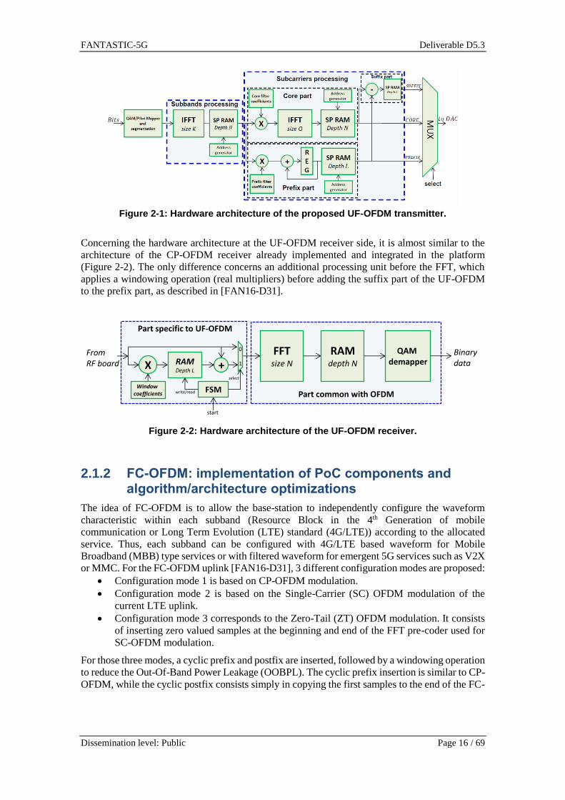
Figure 2-1: Hardware architecture of the proposed UF-OFDM transmitter.
Concerning the hardware architecture at the UF-OFDM receiver side, it is almost similar to the
architecture of the CP-OFDM receiver already implemented and integrated in the platform
(Figure 2-2). The only difference concerns an additional processing unit before the FFT, which
applies a windowing operation (real multipliers) before adding the suffix part of the UF-OFDM
to the prefix part, as described in [FAN16-D31].
Figure 2-2: Hardware architecture of the UF-OFDM receiver.
2.1.2 FC-OFDM: implementation of PoC components and algorithm/architecture optimizations
The idea of FC-OFDM is to allow the base-station to independently configure the waveform
characteristic within each subband (Resource Block in the 4th Generation of mobile
communication or Long Term Evolution (LTE) standard (4G/LTE)) according to the allocated
service. Thus, each subband can be configured with 4G/LTE based waveform for Mobile
Broadband (MBB) type services or with filtered waveform for emergent 5G services such as V2X
or MMC. For the FC-OFDM uplink [FAN16-D31], 3 different configuration modes are proposed:
Configuration mode 1 is based on CP-OFDM modulation.
Configuration mode 2 is based on the Single-Carrier (SC) OFDM modulation of the
current LTE uplink.
Configuration mode 3 corresponds to the Zero-Tail (ZT) OFDM modulation. It consists
of inserting zero valued samples at the beginning and end of the FFT pre-coder used for
SC-OFDM modulation.
For those three modes, a cyclic prefix and postfix are inserted, followed by a windowing operation
to reduce the Out-Of-Band Power Leakage (OOBPL). The cyclic prefix insertion is similar to CP-
OFDM, while the cyclic postfix consists simply in copying the first samples to the end of the FC-
c cFFT
size NFrom RF board
QAM demapper
RAMdepth N
Binary data
Part common with OFDM
X
Windowcoefficients
RAMDepth L
+
FSM
select
write/read
start
0
1
Part specific to UF-OFDM

FANTASTIC-5G Deliverable D5.3
Dissemination level: Public Page 17 / 69
OFDM symbol. Furthermore, the last samples of the symbol number 𝑛 overlap with the first
samples of the symbol number 𝑛 + 1.
Concerning hardware implementation, almost the same components as for UF-OFDM were
reused to implement the FC-OFDM uplink transmitter. It is in fact possible to adapt the hardware
architecture of the proposed UF-OFDM transmitter (Figure 2-1). More details can be found in
[FAN16-D52].
Finally, the FC-OFDM uplink receiver is implemented by adapting the hardware architecture of
the CP-OFDM receiver already implemented and integrated in the platform. It requires an
additional IFFT post-coder of size P to support configuration mode 2 and mode 3 (Figure 2-3), P
being equal to the number of allocated subcarriers.
Figure 2-3: Hardware architecture of the FC-OFDM receiver.
2.1.3 FBMC: implementation of PoC components and algorithm/architecture optimizations
FBMC is a multicarrier transmission scheme that introduces a filter-bank to enable efficient pulse
shaping for the signal conveyed on each individual subcarrier. This additional element represents
an array of band-pass filters that separate the input signal into multiple subcarriers, each one
carrying a single frequency subband of the original signal. As a promising variant of filtered
modulation schemes, FBMC/OQAM, originally proposed in [Sal67], can theoretically achieve a
higher spectral efficiency than OFDM since it does not require the insertion of a CP. Additional
advantages include the robustness against highly variant fading channel conditions and imperfect
synchronizations by selecting the appropriate prototype filter type and coefficients [LGS14].
In the literature, typical implementation of FBMC/OQAM transmitters employ a PolyPhase
Network (PPN) based structure [Hir81]. It is composed of one IFFT followed by one PPN for the
filtering stage, and enables a low complexity implementation of the FBMC/OQAM transceiver.
To support the OQAM scheme, typical FBMC/OQAM implementation duplicates the IFFT and
the PPN. However, such duplication can be avoided at transmitter side leading to an
FBMC/OQAM transmitter with low hardware complexity [NAB15]. The related architecture,
shown in Figure 2-4, is based on a pruned IFFT algorithm described in [DS11] to divide the
computational complexity of the FBMC/OQAM transmitter by almost a factor of two. Specific
details can be found in [FAN16-D52].
Figure 2-4: Low-complexity FBMC/OQAM transmitter hardware architecture.
cccFFT
size NFrom RF board
RAMdepth N
Binary data
Part common with OFDM
RemoveCP
IFFTsize P
RAMdepth P
1
2
3RemoveZero-Tail
QAM demapper
mode
Part specific to FC-OFDM
Part common with OFDM

FANTASTIC-5G Deliverable D5.3
Dissemination level: Public Page 18 / 69
Concerning the receiver side, the pruned IFFT optimization cannot be employed due to the
multipath channel which introduces complex valued coefficients. Thus, two IFFT and two PPN
must be used to perform the demodulation. Furthermore, the equalization procedure tends to be
more difficult when using short filters, when the delay spread of the multipath channel is large or
in case of high timing synchronization errors (relaxed synchronization). The Frequency-Spread
(FS) implementation of the FBMC/OQAM receiver enables to correctly equalize channel
impairments while keeping a simple one-tap equalizer. The principle is to process the filtering
stage in the frequency domain instead of the time domain for the PPN implementation. For this
purpose, the Fast Fourier Transform (FFT) size must be equal to the filter length 𝐿 and followed
by a linear convolution operation with the frequency response of the prototype filter which can
be implemented using a Finite Impulse Response (FIR) filter structure. Then, the obtained filtered
samples must be down-sampled by 𝐿/𝑁, as shown in Figure 2-5. Particularly, since 𝐿 = 𝑁 when
a short filter is used, the FFT size is same as the one used for the PPN implementation. Therefore
the complexity overhead depends on the number of required taps of the FIR structure, which is
negligible when the Near Perfect Reconstruction 1 tap (NPR1) filter is used. The design of this
filter and its advantages are detailed in [FAN16-D52].
Figure 2-5: FS implementation of the FBMC/OQAM receiver.
2.1.4 PoC final version and evaluation results
This section presents the results of the PoC for the MMC scenario, the V2X scenario and the
MCC scenario for each waveform presented in the previous sections. The set of parameters
summarized in Table 2-1 have been chosen for all the presented results in this section. The
hardware complexity of the waveforms is already detailed and compared in Section 2.1.4 of
[FAN16-D52]. Therefore, this section only details the performance of the waveforms in terms of
Bit Error Rate (BER), transmission quality and data rate for each scenario.
Table 2-1: Set of parameters used for the post-OFDM waveforms in the PoC platform.
Parameter Value
FFT size ( = total number of subcarrier) 512
Sampling rate 7.68 MHz
QAM constellation 16-QAM
Number of subcarriers per Resource Block 12
CP length for OFDM & FC-OFDM uplink 36
Filter length for UF-OFDM 37
UF-OFDM sidelobe level (Chebyshev filter) 40 dB
UF-OFDM subband size 16

FANTASTIC-5G Deliverable D5.3
Dissemination level: Public Page 19 / 69
The target PoC environment is illustrated in Figure 2-6 where one board emulates a User
Equipment (UE) physical layer (transmitter side), and a second board is used to emulate the base-
station (receiver side). Both digital processing boards are extended by a Radio Frequency (RF)
interface to enable over-the-air transmission. The TX and RX of different waveforms are
implemented in full hardware on the Field-Programmable Gate Array (FPGA) part of the Zynq-
7000 System on Chip (SoC). The control and interface are ensured by a dual-core Advanced RISC
Machines (ARM) Cortex A9 processor embedded in the Zynq SoC and through the development
of a dedicated Graphical User Interface (GUI). The GUI at the transmitter side is used to select
mapping and modulation parameters like QAM constellation order, FFT and cyclic prefix sizes,
the number of active subcarriers, etc. The GUI at the receiver side displays relevant performance
metrics.
Figure 2-6: Flexible PoC for Post-OFDM waveforms.
2.1.4.1 Massive machine communication scenario results
The first demonstrated scenario on the PoC platform concerns the case of MMC. This
demonstration has been presented during the 5G workshop of the International Symposium on
Turbo Codes & Iterative Information Processing (ISTC) in Brest, 5th-9th September 2016, during
the 2nd Global 5G Event in Rome, 9th-10th November 2016 (Figure 2-7) and in European
Conference on Networks and Communications (EuCNC) in Oulu, , 12th-15th June 2017 (Figure
2-8)
Transmitter side Receiver side
Zynq-7000 All Programmable SoC
AXI Interconnect
config.
Dual-core ARM Cortex-A9 processing system IIC
Int.
Ctr
l
Eth
ern
et
UA
RT
DD
RX
Programmable Logic (FPGA)
AXI Interconnect
DMA
Ctrl.
Slv_Regs
TX Post-OFDM
TX OFDMDMA
AD9361 interface
DA
C L
VD
S In
terf
ace
AD
C L
VD
S In
terf
ace
GUI GUI

FANTASTIC-5G Deliverable D5.3
Dissemination level: Public Page 20 / 69
Figure 2-7: Flexible PoC for Post-OFDM waveforms at the 2nd Global 5G Event.
Figure 2-8: Flexible PoC for Post-OFDM waveforms at the EuCNC’17.
In MMC scenario, eMBB users may coexist with MMC-type users such as sensors; for example,
by sharing the same spectrum resources. Under power and signaling overhead constraints, perfect
synchronization may not be easily ensured. Therefore, interference is created between subcarriers
allocated to different services or even allocated to the same type of services but to different UEs
or sensors. The key aspect of this PoC scenario is to assess the behavior of post-OFDM waveforms
in the context of relaxed synchronization foreseen in MMC. The target PoC setup emulates a
situation where a massive number of sensors send short packets of information to the base-station.
To avoid close-loop synchronization and reduce the power consumption of the sensors, open-loop
synchronization is considered in this demonstration: the sensors wake-up from sleep mode,

FANTASTIC-5G Deliverable D5.3
Dissemination level: Public Page 21 / 69
recover the time-base of the base station and directly transmit, without TA mechanism, the
required few bits of information to the base-station and switch to sleep mode again. In our PoC
demonstration setup, sensors send small-size image files to the base-station for simulating the
transmission of short information at low data rate. These sensors are allocated on different
subcarriers and experience different levels of synchronization misalignment with respect to the
existing, already occupied, fragmented spectrum. The fragmented spectrum is the result of the
transmissions of other sensors or broadband users. Due to the lack of perfect synchronization, the
fragmented spectrum acts as interference for the considered sensors. A guard-band of 2
subcarriers is inserted around the subcarriers allocated to the considered sensor.
Figure 2-9: Obtained results on the PoC platform for MMC scenario.
The transmitter represented in Figure 2-6 is used to simulate a sensor, and the receiver side
simulates the base-station. Additionally, the TX antenna on the receiver board is used to generate
the existing occupied fragmented spectrum (acting as interference).
Figure 2-9 illustrates the obtained performance for MMC scenario for the OFDM, UF-OFDM,
FC-OFDM uplink (mode 1) when a turbo code is employed with a code rate of 1/2. The imperfect
synchronization caused by the open-loop synchronization is simulated by introducing a timing
offset of 8% relative to the symbol duration. For a 66.7 us symbol duration, this corresponds to a
timing offset of 5.3 us. Since this timing offset is longer than the CP length, orthogonality is lost
with adjacent users/sensors when using CP-OFDM, resulting in great performance loss (BER ~
2.10-2) and the compressed image (jpeg) cannot be recovered. While interferences are still present
for UF-OFDM and FC-OFDM uplink (mode 1), the received QAM symbols are less noisy than
OFDM, and the image is perfectly recovered without errors. Therefore, both of these waveforms
are suitable for MMC and are attractive solutions since OFDM-based techniques can be reused
(Peak to Average Power Ratio (PAPR) reduction, MIMO), and are perfectly compatible with LTE
numerology.
Better performances can be achieved with FBMC/OQAM, as shown in Figure 2-9. Particularly,
the PHYDYAS filter enables to perfectly avoid the inter-user interferences due to its strong

FANTASTIC-5G Deliverable D5.3
Dissemination level: Public Page 22 / 69
frequency localization, since no errors are introduced in the received bits even without a forward
error correction code. Furthermore, the guard interval can be reduced to 1, which increases the
spectral efficiency. However, such long filter requires a higher number of symbols in a frame to
avoid significant data rate losses due to the filter tail, resulting in high Time Transmission Interval
(TTI) and higher latency. When using FBMC/OQAM with Time Frequency Localization 1 tap
(TFL1) short filter, interferences are not removed, but are at lower level than FC-OFDM and UF-
OFDM: a code rate of 4/5 is sufficient to perfectly recover the image. Furthermore, the filter
length being equal to the length of an OFDM symbol, the filter tail length is reduced and only 14
OQAM symbols (= 7 FBMC symbols) per frame are considered to achieve the same data rate as
OFDM with CP. Therefore, the same TTI as LTE can be obtained when using a short filter without
any data rate loss. However, the bottleneck of FBMC/OQAM is clearly the difficulty to use
MIMO diversity schemes, such as the Alamouti coding a.k.a Space-Frequency-Block-Code
(SFBC), due to its inherent overlapping structure. Nevertheless, several promising techniques are
under investigation to resolve this particular issue.
2.1.4.2 Vehicular communication scenario results
The second demonstrated scenario concerns V2X communication. This scenario corresponds to
the establishment of communication links in mobile environments such as between the classical
infrastructure and a moving vehicle, or communication between vehicles (V2X). The purpose is
to illustrate the robustness of post-OFDM waveforms against Doppler effects compared to CP-
OFDM. Such impairments appear in a situation where users are subject to high Doppler, for
instance in a high speed vehicle, or in a train. The PoC implements a situation where a user in a
high speed vehicle uploads an image or a streaming video to the base-station (uplink
communication). The effect of high mobility is emulated directly in hardware by the introduction
of a respective carrier-frequency offset. Such an effect is simple to emulate in hardware and
corresponds to the case where a direct path is available and dominant in terms of received power.
Nevertheless, a more complete channel model should consider the other cases that imply Doppler
spread effect. Note that the Carrier Frequency Offset (CFO) is assumed to be known at the receiver
side. Therefore, the phase rotation is compensated.
The image and constellation points are received in a high mobility condition of 600 km/h,
corresponding to ~9% CFO considering a carrier frequency of 2.4 GHz. It can be shown in Figure
2-10 that the received QAM symbols are corrupted by Inter-Carrier Interference (ICI) for the case
of CP-OFDM, UF-OFDM and FC-OFDM. For CP-OFDM, a code rate of 1/2 is necessary to
recover the image, with a BER of ~4.10^6. With the same code rate, the image is perfectly
recovered with a BER of 0 in the case of UF-OFDM and FC-OFDM, which represents a slightly
increased performance. Concerning FBMC/OQAM with the PHYDYAS filter, the ICI is clearly
reduced since the constellation points are less noisy than with CP-OFDM, and no errors are
introduced in the received bits when using a code rate of 2/3. When a shorter filter is used, better
performance is obtained, since the received constellation is less noisy than PHYDYAS filter as
shown in Figure 2-10. These results are compliant with the analysis conducted in state-of-the-art
[LGS14]. For this case, a code rate of 4/5 is sufficient to obtain a BER of 0, enabling to improve
the data rate when compared to PHYDYAS filter. This demonstrates the improvement in
transmission quality that can be offered by the FBMC/OQAM modulation in a scenario related to
high mobility when using the TFL1 filter.

FANTASTIC-5G Deliverable D5.3
Dissemination level: Public Page 23 / 69
Figure 2-10: Obtained results on the PoC platform for V2X scenario.
2.1.4.3 Mission Critical Communication scenario results
The third demonstrated scenario concerns MCC, where low latency and reliability are the most
important requirements. An efficient way to reduce the latency is to increase the subcarrier
spacing from 15 kHz (typical LTE setup) to 30 kHz. By consequence, the length of the TTI
(corresponding to the transmission time of 14 symbols) is halved, which in turn reduces the frame
duration and the latency. However, when using OFDM, the orthogonality is only ensured if the
subcarrier spacing is the same for each user. When users employ different subcarrier spacing,
there is a coexistence issue since inter-user interferences occur, degrading the reliability of the
communication, or reducing the data rata if guard-bands are introduced. Therefore, CP-OFDM is
not adapted for MCC, and it is expected that waveform relying on filtering will generate less inter-
user interference, as it the case for the post-OFDM waveform considered in this PoC.
To illustrate the coexistence of MCC with other services, the PoC implements a scenario where a
primary user wants to send an image using with MCC-like requirements, while a secondary user
communicates with the base-station using typical LTE-like requirements. To achieve a low
latency communication between the primary user and the base-station, the subcarrier spacing of
the primary user is set to 30 kHz, while the secondary user has a subcarrier spacing of 15 kHz. It
is assumed that both users are synchronized with the base-station (typical closed loop
synchronization), and both users employ the same waveform. A guard-band is also introduced
between the bandwidth occupied by the two interfering users. The transmitter represented in
Figure 2-6 is used to simulate the primary user, while the TX antenna of the receiver side transmits
the data related to the secondary user. At the base-station only the primary user is demodulated.
Figure 2-11 illustrates the obtained performance for MCC scenario for the CP-OFDM, UF-
OFDM, FC-OFDM uplink (mode 1, based on CP-OFDM modulation) when a turbo code is
employed with a code rate of 1/2. A guard-guard of 12 subcarriers (at 15 kHz) is inserted between
the primary and the secondary user. As expected, the orthogonality is totally lost for the case of
CP-OFDM, resulting in great performance loss (BER ~ 4.10-2) and the compressed image (jpeg)
cannot be recovered. While interferences are still present for UF-OFDM, the received QAM
symbols are less noisy than CP-OFDM, and the image is perfectly recovered without errors. For

FANTASTIC-5G Deliverable D5.3
Dissemination level: Public Page 24 / 69
FC-OFDM, better results are achieved than CP-OFDM, but residual errors remain. Therefore,
both of these waveforms can be suitable for MCC.
Figure 2-11: Obtained results on the PoC platform for MCC scenario.
Concerning FBMC/OQAM modulation, no interferences are introduced when a guard-band of 12
subcarriers is employed for the TFL1 and the PHYDYAS filters, as shown in Figure 2-11.
Therefore, the code rate can be set to 1 to achieve full data rate. However, the FBMC/OQAM
symbols using PHYDYAS filter have a duration 4 times longer than an OFDM symbol. Therefore,
the latency is greatly increased, since around 0.1 ms (at 30 kHz of subcarrier spacing) of
additional latency is required to demodulate one symbol, reducing its suitability for MCC
scenario. On the other hand, short filters like TFL1 have the same duration as one CP-OFDM
symbol, and are therefore more adapted for MCC scenario. Still, the latency is slightly higher than
CP-OFDM, due to the OQAM scheme (~16.67 μs of additional latency at 30 kHz of subcarrier
spacing).

FANTASTIC-5G Deliverable D5.3
Dissemination level: Public Page 25 / 69
2.2 FBMC-MIMO transceiver based on software programmable hardware
CEA-LETI proposed during the course of the project a new multicarrier waveform that combines
elements of CP-OFDM and FBMC. This waveform, called Block Filtered OFDM (BF-OFDM),
is quasi orthogonal in the complex domain, allowing the usage of usual MIMO schemes such as
Alamouti or spatial multiplexing. Details of this waveform are given in [FAN16-IR32].
The flexible 2x2 MIMO FBMC-like transceiver developed by CEA is based on software
programmable hardware including a large Zynq FPGA for baseband processing, an ARM dual
core processor for the control and an off the shelf RF front-end. Detailed description can be found
in [FAN16-D51] [FAN16-D52].
The objective of this PoC is to combine an FBMC-based waveform (BF-OFDM) with a 2x2
MIMO scheme, with real time Hardware (HW) / Software (SW) implementation in order to assess
the feasibility of such proposal. The goals of the PoC are threefold: demonstrate that FBMC-based
waveform is compatible with MIMO, show the impact of 5G waveform on legacy LTE (where
co-existence between the waveforms in adjacent bands is considered) and investigate the frame
structure for FBMC.
2.2.1 Implementation of PoC components and algorithm/architecture optimizations
The following section gives a detailed overview over the implemented PHY features of the 5G
MIMO 2x2 downlink transceiver. This section is kept from [FAN16-D52] for sake of clarity. The
downlink transmitter and receiver include the implementations of the following channels:
- Primary Synchronization Channel (PSCH), built from a Zadoff-Chu sequence.
- Secondary Synchronization Channel (SSCH), built from a Zadoff-Chu sequence.
- Physical Downlink Broadcast Channel (PDBCH): in our proposed application, it carries
information about the cell and the set of the active physical resource blocks available for
allocation.
- Reference signals, based on distributed pilots (time/frequency).
- Physical Downlink Control Channel (PDCCH). This channel carries the UE allocation
information, i.e. active Resource Block (RB) and Modulation-Coding Scheme (MCS) per
user.
- Physical Downlink Shared Channel (PDSCH).
The frame format for antenna 0 is depicted in Figure 2-12.
The downlink receiver receives the IQ samples in time domain from the RF. The Digital Front
End (DFE) performs the IQ impairment compensation, digital down conversion, frequency shift
and the down conversion from the Analog to Digital Converter (ADC) sample rate to the minimal
sampling frequency.
The first processing step in the downlink receiver is the synchronization. Coarse time domain
synchronization is performed. Then the primary and secondary synchronization signals are used
for radio-frame synchronization. Carrier Frequency Offset (CFO) estimation as well as
compensation is also realized based on an estimation derived from the synchronization
algorithms. When the receiver has two receive antennas, the initial synchronization is done on the
antenna port with the maximum received power. The primary synchronization signal is detected
by a 1 bit correlator. Only a subset of possible positions is checked thanks to the a priori
knowledge from the coarse synchronization procedure. To avoid misdetection, a validation unit
checks that the peak amplitude is higher than a given threshold. After multiple synchronization
signals are detected consecutively the position of the start of the radio frame is calculated. This
position is used to pass an entire time-aligned radio frame to the subsequent modules.

FANTASTIC-5G Deliverable D5.3
Dissemination level: Public Page 26 / 69
Figure 2-12: Frame format for antenna 0. A small set of RB is depicted.
After the frequency domain transformation, physical downlink channels are decoded. First the
Physical Broadcast Channel (PBCH) channel is extracted. The PSCH and SSCH are used to
perform channel estimation. Linear interpolation is used to compute the channel coefficients for
each Resource Element (RE). Then each RE is equalized and Quadrature Phase Shift Keying
(QPSK) demapping is performed with corresponding Log Likelihood Ratio (LLR) computation.
Then the transport channel is decoded after de-interleaving, de–rate matching and Viterbi
decoding. The Cyclic Redundancy Check (CRC) is performed and if no error is detected, the BCH
message is extracted to determine the set of active RBs available for allocation. If the CRC is not
correct, a new synchronization process is activated.
When the message carried by the PBCH is decoded, the active RBs are extracted for each antennas
and the PDCCH channel is decoded to determine the UE allocations. After that reference signals
are demodulated for each receive antenna. Channel coefficients at reference signal locations are
estimated after amplitude and sign compensation. A fine CFO and the Channel Impulse Response
estimation are processed. Based on that, a frequency linear interpolation is performed followed
by a time interpolation. The time interpolation is limited to a linear interpolation on 1 ms. Channel
coefficients for each resource element are stored and fed to the next processing blocks.
Given the active REs and the corresponding channel coefficients, PDCCH symbols are equalized.
LLRs are then fed to the transport channel decoder. If the CRC is valid, the UEs allocation is
extracted. If the control manager detects that a resource block is dedicated to the UE of interest,
the MCS and active RBs are interpreted and the PDSCH decoder’ chains are configured
(modulation, detector, rate matching, interleaver …) and activated. PDSCH are decoded and
payload bits are sent to next layer when the CRCs are valid.
Main blocks of the implemented transceiver architecture were already described in [FAN16-D52].
In the following sub-section, we only describe the blocks added since the publication of the
previous deliverable.
2.2.1.1 Key building blocks description
2.2.1.1.1 BF-OFDM transmitter
The two BF-OFDM transmitters are implemented using IFFTs and the PPN. The BF-OFDM
architecture is illustrated in Figure 2-13. A pre-distortion stage is first applied to the complex
samples. The pre-distortion stage is simply a multiplication of the complex QAM symbols by a
complex factor. There exist 32 values, one for each subcarrier. The pre-distortion coefficients are
stored into a memory bank (32-element ROM). Then a 64 point IFFT is computed. As mentioned
previously, only 32 samples are non-zero. The output samples of the IFFT are stored in a buffer
composed of two memory banks implementing a “ping-pong” buffer. The mapping of the
memory is given Figure 2-14.

FANTASTIC-5G Deliverable D5.3
Dissemination level: Public Page 27 / 69
Figure 2-13 : Architecture of the BF-OFDM transmitter. Blue boxes are for the logic while green are for the memories.
Samples are written in row (green arrow) and read in column and samples fed the 128 points
IFFT. The insertion of the CP is realized by reading 64+NCP columns of the buffer.
Figure 2-14: BF-OFDM buffer mapping.
The output samples of the 128 points IFFT are then fed to a filter-bank parameterized by a
prototype filter with an overlapping factor K. As in typical FBMC transmitter, an overlap and
sum operation is realized by the PPN. Symbols are then transmitted each M/2 samples.
At the receiver, the main building blocks are time domain synchronization, deframer, soft output
MIMO decoder, Zero Forcing (ZF) decoder, LLR computation and Forward Error Correction
(FEC).
2.2.1.1.2 Channel estimation
Channel estimation is an important issue for the MIMO scheme since computational complexity
increases with the number of antennas. In our case, the system was designed to support a 2x2
MIMO scheme. As a consequence, four channel state information (CSI) should be estimated. In
the estimation process of the channel, CSI on pilot tones are first estimated using the well-known
least square process and then temporally stored into a buffer (implemented as a First-In-First-Out
(FIFO)). A frequency interpolation is then performed on the 4 channels and the output of the
interpolation is buffered into the Channel Impulse Response (CIR) memory. For each slot all the
bandwidth is interpolated whatever the allocation of the user of interest. Indeed, the receiver (RX)
was designed to support the full-bandwidth allocation of a user, i.e all RBs can be allocated at a
given time to the same user. Secondly, a time interpolation is computed. To limit the complexity
and more precisely, the amount of required memory, a linear interpolation is implemented.
Thanks to the regularity of the pilot tones locations, the interpolation coefficients can be
efficiently stored in a small look-up table to reduce the hardware cost. In parallel of the time
interpolation process, a fine CFO estimation is computed by estimating the average phase shift
over consecutive (in time) pilot tones. As a summary, the proposed architecture of the Channel
estimation function is depicted in Figure 2-15.

FANTASTIC-5G Deliverable D5.3
Dissemination level: Public Page 28 / 69
Figure 2-15: Architecture of the channel estimation function. LLR computation
2.2.1.1.3 Low level software description
In the previous section, hardware building blocks were discussed. In this section we describe the
architecture of the developed low level software (i.e. the PHY driver). The drivers were
implemented in C (gcc compiler for ARM target). Multi-threading architecture is defined in order
to benefit from the multi-core processor (multiple threads are therefore executed concurrently).
2.2.1.1.3.1 Transmitter
The architecture of the transmitter (TX) PHY driver is depicted in Figure 2-16. A first thread is
dedicated to the higher layer interface. It gets stream to transmit, formats the message and
forwards the packet to one of the 8 FEC (Forward Error Correction) processing threads according
to the configuration set by the scheduler. The number of FEC processing threads is related to the
maximum number of users that can be scheduled per TTI in the current implementation.
The FEC processing thread encodes the signal (including scrambling, CRC insertion and
interleaving and puncturing functions). Messages are then sent to the HW interface thread. This
thread merges and formats the output of each FEC threads. A new message is built and forwarded
to the FPGA drivers.
Eventually the role of the scheduler and low level configuration thread is twofold:
- Scheduling of the users according to a configuration received from a dedicated interface.
The scheduling algorithm is not implemented in this thread.
- Low level configuration. Using an appropriate GUI, it is possible to monitor and
configure low level registers. For instance, output level, internal level quantization and
FIFO monitoring can be adjusted or checked.

FANTASTIC-5G Deliverable D5.3
Dissemination level: Public Page 29 / 69
Figure 2-16: Multi-Thread architecture of the PHY TX driver.
2.2.1.1.3.2 Receiver
The RX PHY driver is divided into 4 threads and the architecture is depicted in Figure 2-17. The
thread “Output Data Collecting” checks the status of the HW output FIFOs (from FEC IP cores)
and reads the bit stream. This thread formats the messages and also performs statistical
evaluations (throughput, CRC error rate). The thread is woken up when the synchronization is
acquired.
The Time Domain (TD) synchronization monitoring thread monitors the output of the TD
synchronization processor (lock status, CFO estimate…). An exemplary log is given in Figure
2-18 . This thread also implements the cell search procedure. Indeed, the precision of the RF
oscillator is quite bad, and therefore the CFO could be in the range [-50, 50] kHz. PBCH tentative
decoding is done for each frequency offset. When the PBCH is correctly decoded (a statistic is
evaluated on CRC), the cell search ends and the PHY layer can be configured according to the
eNodeB allocated RBs extracted from BCH signaling.
The PBCH decoding threads reads IQ samples (IQ antenna 0 and 1) from the HW. CSI is then
estimated, LLR are computed followed by the channel decoding process and the de-framing of
the message (when the CRC is ok). A blind estimation of the Signal to Noise Ratio (SNR) is also
computed. It should be mentioned that real time processing is not required for the PBCH
processing.
Figure 2-17: Multi-Thread architecture of the PHY RX driver.
Eventually, a monitoring thread allows to display measurements such as constellation, CFO value,
CIR etc. It is also possible to read or/and write low level configuration register to adjust

FANTASTIC-5G Deliverable D5.3
Dissemination level: Public Page 30 / 69
quantization, thresholds etc. A dedicated interface to Matlab has been developed, allowing quick
development of a GUI.
Figure 2-18: Snapshot of the log messages from RX PHY
2.2.2 PoC final version and evaluation results
2.2.2.1 Complexity assessment
This section sums up the FPGA synthesis results targeting Xilinx xc7z-045ffg676-1. The
complexity of the design for each block is given by the amount of Slice Registers, Look-Up-Table
(LUT) and DSP48E1 cells used by the different modules of the design. Slice Registers correspond
to the amount of register cells used, while LUT to the amount of combinatorial logic in the design.
DSP48E1 cells are Digital Signal Processing (DSP) cells dedicated to multiplication and
accumulation operations. The design is constrained by its clock frequency that is set to 140 MHz.
The FFT size at the receiver is equal to 4096, with M=128, N=64 and NCP=4.
2.2.2.1.1 Transmitter complexity
The complexity of the flexible transmitter is given by the amount of Slice Registers, LUT and
DSP48E1 cells used by the different modules of the design. Slice Registers correspond to the
amount of register cells used, while LUT to the amount of combinatorial logic in the design.
DSP48E1 cells are DSP cells dedicated to multiplication and accumulation operations. The
amount of cells used by the transmitter (2 antennas port) is summarized in Table 2-2. More than
the absolute complexity values of each transmitter modules, a relative complexity comparison
between these modules for the different hardware elements in the FPGA is interesting to analyze
(see Figure 2-19).
Table 2-2: Complexity of the BF-OFDM transmitter (2 antenna ports).
TX Total Available
Slice LUTs 29.362 218.600
Slice register 43.192 437.200
Block RAM 83 545
DSP 192 900

FANTASTIC-5G Deliverable D5.3
Dissemination level: Public Page 31 / 69
Figure 2-19 FPGA hardware components usage for the BF-OFDM transmitter.
The FPGA interface is the module dedicated to the interface between the programmable matrix
and the processor. It includes the AXI bus, the bus management and the memory controller
(including DMA). The DAC/ADC interface module provides a bridge between the programmable
matrix and the RF component. The Framing module gets data from the processor, performs the
QAM modulation and inserts reference signal as well as control channel (BCH, PDCCH)
As expected, most of the complexity (Slice LUT, DSP and Slice register) is to be found in the
inverse FFTs. 45% of the Block RAM is required for the two PPNs (one per antenna). Although
the amount of DSPs is relatively low, their usage is almost equally split between IFFT
implementation and PPN filtering.
2.2.2.1.2 Receiver complexity
The amount of cells used by the receiver is summarized in Table 2-3. The receiver integrates the
processing of two antenna ports. More than the absolute complexity values of each receiver
modules, a relative complexity comparison between these modules for the different hardware
elements in the FPGA is interesting to analyze (see Figure 2-20).
Table 2-3: Complexity of the BF-OFDM receiver.
RX
(2 Antennas port)
Total Available
Slice LUTs 103.981 218.600
Slice register 86.296 437.200
Block RAM 318 545
DSP 344 900
As expected, the most significant amount of memory, DSP and LUT usage comes from the TD
and Frequency Domain (FD) processors. The complexities of the two FEC processors are
negligible. However, it should be underlined that only convolutional decoding is implemented.
The use of a more powerful FEC scheme (Low Density Parity Check (LDPC) or Turbo) would
dramatically increase the complexity of the FEC.

FANTASTIC-5G Deliverable D5.3
Dissemination level: Public Page 32 / 69
Figure 2-20: FPGA hardware components usage for the BF-OFDM receiver.
Concerning the TD processor, most of the DSP is to be found in the two FFTs (one per antenna)
while, for slice LUT, the Time domain correlation is the most resource consuming as illustrated
in Figure 2-21.
Figure 2-21: Complexity of the TD processor for BF-OFDM.
Eventually the analysis of the complexity of the time domain synchronization shows that the
complexity is dominated by the Fine synchronization module. The Fine synchronization module
performs a correlation on a selected window of samples (see Figure 2-22).

FANTASTIC-5G Deliverable D5.3
Dissemination level: Public Page 33 / 69
Figure 2-22: Complexity of the Time domain synchronization for BF-OFDM.
Concerning the FD processor, the usage of the memory is dominated by the LLR storage. The
design was configured to support the full allocation of a user using a 2x2 64QAM scheme. The
repartition of the complexity of the FD processor is given in Figure 2-23.
Figure 2-23: Complexity of the Frequency domain processor for BF-OFDM.

FANTASTIC-5G Deliverable D5.3
Dissemination level: Public Page 34 / 69
This includes the non-negligible overhead the flexible implementation has put on the design.
Control is taking almost 30% of the design area (PDCCH decoding + control). As expected, the
complexity is dominated by the channel estimation (20%) as well as the equalizer (50%).
2.2.2.2 KPI
Various KPI are available with this PoC. Concerning the transmitter, the power spectral density
can be measured. A signal composed of various users who are allocated in the time frequency
grid was built. Two RBs are not allocated (no pilot, no payload) to demonstrate the good
frequency localization of the waveform. The signal is modulated at 2.4GHz. A snapshot from a
spectrum analyzer is given in Figure 2-24.
Figure 2-24: PSD measurement for BF-OFDM.
The spectrum shape shows a very steep inband and out-of-band roll-offs. This confirms the
simulation results and the good frequency localization properties of BF-OFDM.
Others KPIs were evaluated using a dedicated Graphical User Interface. In particular, CFO
tracking, Error Vector Magnitude (EVM), CRC error rate, and instantaneous throughput are
tracked and displayed. A snapshot of the GUI is depicted in Figure 2-25.
As mentioned previously, the RX is generic and was designed to support the allocation of a user
on the whole-bandwidth (all RB). The expected peak throughput is then:
- 48.8Mbits/s, with 64-QAM 4/5 Single Input Single Output (SISO) – 10MHz mode
- 97.6Mbit/s, with 64-QAM 4/5 SISO - 20MHz mode
- Up to 195.2Mbit/s, for a 2x2 spatial multiplexing MIMO (@20MHz bandwidth).
The previous bit rates were given with real time implementation. There is also a 256-QAM mode
which is obtained through HardWare-In-the-Loop (HWIL) approach where the expected
throughput is 240 Mbit/s.

FANTASTIC-5G Deliverable D5.3
Dissemination level: Public Page 35 / 69
Figure 2-25: Monitoring GUI for BF-OFDM.
Regarding the complexity, it should be underlined that the complexity of an OFDM receiver is
the same as the complexity of the proposed BF-OFDM receiver. However, concerning the
transmitter, the complexity of the proposed scheme is higher due to the filtering function (PPN
21% DSP and 40% Block RAM). A significant overhead in memory is necessary but this
overhead may not be as costly in silicon design as memory blocks are highly optimized for
occupancy. Concerning the iFFTs, when comparing OFDM and BF-OFDM, the complexity of
the proposed design is 1.6 times greater for LUT, but 0.6 times lower for Block RAM and 0.8
time lower for DSP. For these latter results, we have evaluated the ratio of complexity between
the two IFFTs (64 and 128 points) required for BF-OFDM and an IFFT of size 4096 (size of the
RX FFT). Besides, as the modulated signal is shaped digitally at the baseband, no compromise
on the transmitter frequency agility is required.
2.2.2.3 Demonstrations
A first demonstration of the PoC was achieved at European Conference on Networks and
Communications (EuCNC) in June 2016 (see the Figure 2-26 below), following a HWIL approach
where the digital modem was implemented in Matlab and the CEA’s baseband board was used as
input/output buffer and digitizer (as an USRP). Achievements were the following:
Demonstration of compatibility of BF-OFDM with MIMO and LTE signaling (following
LTE-like frame structure depicted in Figure 2-12).
Spectral efficiency up to 12 bit/s/Hz (256-QAM, 2x2, 3/4).
Coexistence with legacy OFDM-based transmission (LTE-M), as can be seen on Figure
2-26 below (5G waveform on the left hand side of the spectrum and LTE-M spectrum on
the right hand side).
Fragmented spectrum usage is addressed digitally.

FANTASTIC-5G Deliverable D5.3
Dissemination level: Public Page 36 / 69
Figure 2-26: CEA’s demonstration at EuCNC 2016.
A second demonstration of the PoC was done at ICC end of May 2017 (Figure 2-27), with real
time HW/SW implementation of the whole transceiver, showing that the proposed 5G transceiver
could fit in a Xilinx xc7z-04 with a limited additional complexity since the receiver is compatible
with OFDM-based processing.
Figure 2-27: CEA’s demonstration at ICC 2017.

FANTASTIC-5G Deliverable D5.3
Dissemination level: Public Page 37 / 69
2.3 Pulse shaped OFDM for TA-free low latency transmission
2.3.1 Asynchronous transmission using P-OFDM waveform
2.3.1.1 Evaluation scenario
The PoC platform for asynchronous transmission using pulse shaped OFDM (P-OFDM) has been
designed for demonstrating an uplink scenario. A typical setup consists of three UEs transmitting
short burst type data blocks to a base station. The UEs occupy subbands which are close to each
other with only one subcarrier used as the guard band. Prior to the data transmission, no Timing
Adjustment (TA) procedure was carried out. This PoC aims to show that an appropriate waveform
design is capable of handling timing offset up to the symbol level.
In Figure 2-28, a block diagram of the evaluation setup is depicted. For simplicity, only two UEs
are considered for this experiment. The target UE varies the transmit power and starts
transmission at an arbitrary time. The interferer transmits at the first neighboring subband with a
fixed transmit power which is significantly higher than the target UE. This can be interpreted as
strong interference generated by a UE close to the base station with poor power control. The BER
is evaluated for the target UE as a performance indicator for link performance. The system setup
parameters are as follows: the sampling frequency is 25 Msps, carrier frequency is set to 2 GHz,
subcarrier spacing is 48.8 kHz while the symbol duration is 20.5 us, CP overhead for OFDM is
1/16.
Figure 2-28: System setup for link performance evaluation in asynchronous uplink scenario
2.3.1.2 Results
The demo evaluates the link performance for asynchronous uplink transmission in the following
three scenarios:
1. Only target UE transmits with the variable transmit power, i.e., there is no interference. We
evaluate the link performance of both P-OFDM and OFDM-enabled transmissions.
2. Target UE transmits with the variable transmit power while the interferer transmits at the first
neighboring subband with 40 dB SNR (SNR here is defined as the ratio between the receiver
power of the interferer and the noise). Both P-OFDM and OFDM-enabled transmissions are
evaluated.
3. Same as scenario 2 except that the interferer transmits with 20 dB SNR. Only OFDM-enabled
transmission is evaluated.
The link performance of above-mentioned three scenarios are illustrated in Figure 2-29. It is
observed that for the interference-free scenario 1, both OFDM and P-OFDM achieve comparable
link performance; in the strong-interference limited scenario 2, OFDM is subject to severe link
performance degradation while P-OFDM exhibits robustness against the interferer; even in
scenario 3 when the interference level is reduced, OFDM still suffers from the performance
degradation compared with interference-free scenario.

FANTASTIC-5G Deliverable D5.3
Dissemination level: Public Page 38 / 69
Figure 2-29: Demonstrated link performance of asynchronous transmission
The visualizations of the demo for P-OFDM and OFDM for Scenario 2 are depicted in Figure
2-30 and Figure 2-31, respectively. In each figure, the upper-left part depicts the power spectral
density of the coexistence of target and interfering UEs. The constellation of target UE (User 1)
and interfering UE (UE2) are shown in the upper-right part (UE3 is not transmitting). The
successful demodulated data flow is painted with respective colors in the lower subfigure (e.g.,
UE1 and UE2 data in Figure 2-30) while the unsuccessful transmit data is painted with grey color
(e.g., UE1 data in Figure 2-31). The visualization imprints the superior performance of the P-
OFDM in support of asynchronous transmission.
Figure 2-30: Visualization of P-OFDM performance for asynchronous uplink transmission

FANTASTIC-5G Deliverable D5.3
Dissemination level: Public Page 39 / 69
Figure 2-31: Visualization of OFDM performance for asynchronous uplink transmission
2.3.2 Single link real time evaluation in high velocity scenario
The field trial for single link real-time evaluation is performed in the public streets of the office
building area around Huawei German Research Center in Munich. Two test cars were driving and
communicating with each other while the test data were modulated in conventional OFDM or P-
OFDM waveforms. The trajectory of two test cars is illustrated in Figure 2-32. The channel
between the direct links has experienced both Line of Sight (LOS) and Non Line of Sight (NLOS)
cases (NLOS case happens when one vehicle is blocked by the buildings between two vehicles).
The driving speeds of the two cars range from 0 to 50km/h resulting in the highest relative speed
of 100km/h when they drive in the opposite direction. The radio test bed consists of one Universal
Software Radio Peripheral (USRP) X310 RF frontend, baseband processing PC and a dipole
antenna mounted on top of a car. Selected photos of field trial are shown in Figure 2-33 regarding
the baseband processing PC inside the car, as well as the exterior of the test vehicle.
Figure 2-32: Trajectory setup for single V2V link real-time field trial

FANTASTIC-5G Deliverable D5.3
Dissemination level: Public Page 40 / 69
Figure 2-33: Real-time field trail photos: Baseband processing PC and test car
The key parameters applied in field trial are listed in Table 2-4. For each received frame, the
estimated SNR and CRC result are recorded. Both OFDM and P-OFDM waveforms are tested in
the same environment.
Table 2-4: Key parameters in field trial.
Parameters Values
Carrier Frequency 2.6GHz
Bandwidth 10MHz
Equivalent CP Overhead 1/4
Frame Length 0.5ms
Code Rate of Turbo coding 1/3
In Figure 2-34, the link performance is summarized in the form of Block Error Rate (BLER) vs.
SNR plots using the data collected. The subcarrier spacing is set to 24.4 kHz and the transmit
power is 7 dBm. Both performance of OFDM and P-OFDM are plotted for comparison. It shows
that P-OFDM outperforms over OFDM attributed to the capability of ICI mitigation by low-out-
of-band-leakage pulse-shaping filter as well as better collection of the receive energy with the
matched filter at the receiver.
The latency performance is evaluated in terms of the radio interface latency vs. the number of
decoding iterations at the receiver. The reason to choose the number of decoding iterations is that
Turbo coding is still the dominant factor to the receiver processing time. Figure 2-35 shows the
latency performance from field trial measurements. We assume the maximum number of Turbo
decoding iterations is 5, i.e., a NACK is sent if the CRC still fails after five decoding iterations.
MCS 3 is chosen with QPSK modulation. FFT size is set to 256 with CP overhead equal to 64.
Subcarrier spacing is set to 60 kHz. Assuming 17 symbols in one TTI and the 4 pilot symbols in
the first, sixth, twelfth, and seventh symbol. The transmit power is set to 8 dBm. TB Size of 209
Bytes is used without Medium Access Control (MAC) Header.

FANTASTIC-5G Deliverable D5.3
Dissemination level: Public Page 41 / 69
Figure 2-34: Link performance of real-time field trial
Figure 2-35: Latency performance vs. the number of decoding iterations at the receiver in field trials
Apart from the field trial, single link real-time evaluation for high velocity scenario is also
performed with indoor test bed and channel emulator. The system setup is shown in Figure 2-36.
The radio test bed consists of two USRP RF frontends, baseband processing PC and PropSim F32
channel emulator which can emulate the channel models from literature, synthetic models or
measurement campaigns.

FANTASTIC-5G Deliverable D5.3
Dissemination level: Public Page 42 / 69
Figure 2-36: Testbed system setup for diversity and array gain performance evaluation: high velocity scenario with channel emulator
We evaluate the receiver diversity and array gain performance using this test bed. The system
parameters are as follows: we use two receive antennae and Maximum Ratio Combing (MRC)
scheme at the receiver. Subcarrier spacing is set to 60 kHz. Modulation scheme is QPSK and
Turbo code rate of 1/3 is employed. 3GPP Extended Vehicular A (EVA) channel at 2.6GHz is
applied with 70 kmph velocity. Least square channel estimation and Minimum Mean Square Error
(MMSE) equalization is applied at the receive side. Pilot symbols are distributed in time-
frequency with 3-symbol distance in between and 3 dB power boost.
The link performances of BLER w.r.t. different channel correlation factors are shown in Figure
2-37. As expected, the system applying the MRC receiver with low correlation outperforms the
one with high correlation. Compared to one antenna settings, two antennae with complete
correlation achieves array gain in the practical settings without any ideal assumptions.
Figure 2-37: Link Performance of testbed using channel emulator

FANTASTIC-5G Deliverable D5.3
Dissemination level: Public Page 43 / 69
2.4 Post- and Parameterized-OFDM waveforms for low latency transmission
Wireless ultra low latency (ULL) communication requires an optimized physical layer, e.g.
through adjustments of the common symbol duration and a redesign of the radio frame structure.
Furthermore, the data and control channels have to be adapted, including the reference and
synchronization signal design. In a first attempt towards a New Radio PHY implementation, we
did modifications on LTE as our baseline system for 5G latency-constrained communication. To
achieve this, we applied two concepts:
Scaling of subcarrier spacing, by using a common sample rate of 30:72 MHz for different
FFT sizes, which in fact leads to an overclocking of the LTE system.
Scheduling based on reduced transmission time intervals, by using a short TTI (sTTI) of
less than 14 OFDM symbols.
This section summarizes the activity and is presented to complete the deliverable. The task was
terminated after the first year of the project and the full technical description can be found in D5.2.
2.4.1 Implementation of PoC components and algorithm/architecture optimizations
The primary and secondary synchronization sequences (PSS and SSS) in Figure 2-38 are marked
with blue colors. The first OFDM symbol of a group of 7 OFDM symbols is marked with light
rose color. This corresponds to the OFDM symbol with 160 time samples, while gray OFDM
symbols contain 144 time samples. This is done in order to achieve symbol termination on a
subframe boundary over mixed numerologies such that all radio frames can be terminated at a
millisecond boundary. We use rate 1/2 convolutional coding to support reliable user plane
transmission and real-time signal processing for short packet sizes. For the implementation, we
use a self-developed SDR hardware platform as described in [WMP+15]. It consists basically of
two components: First, a high performance DSP platform, equipped with two SoCs each with four
DSP cores, several accelerators and high speed interfaces. Second, a flexible remote radio head
with up to eight antenna ports and tunable frequency range of 70 MHz to 6 GHz. Both are
interconnected via the high-speed Common Public Radio Interface (CPRI) as optical fiber link.
Figure 2-38: Potential ULL radio frame structure [WHM+16].
0 0.25 0.5 0.75 1-1
0
1
Am
pli
tud
e LTE Subframe Structure (k=1)
0 0.25 0.5 0.75 1-1
0
1
Am
pli
tud
e ULD Frame Design (k=2)
0 0.25 0.5 0.75 1
OFDM Symbols / Time [ms]
-1
0
1
Am
pli
tud
e ULD Frame Design (k=4)
PSSSSS

FANTASTIC-5G Deliverable D5.3
Dissemination level: Public Page 44 / 69
2.4.2 PoC final version and evaluation results
We evaluate the one-way latency performance based on approximately 10 million transmitted
packets over a single short wireless link, using one transmit and one receive antenna. The full
system setup is described in [PMW+16]. An intermediate version of this PoC has been presented
during the EuCNC in June 2016, see Figure 2-39.
Figure 2-39 Presentation of HHI – low latency testbed at EUCNC 2016
For the evaluation, we refer to User Datagram Protocol (UDP) packets of 32 Bytes payload size
of randomized data which are streamed in short Ethernet frames. The latency statistics for
different Ultra Low Latency (ULL) system parameters are shown in Figure 2-40. Even for highest
percentiles, e.g. in 99.999% of the transmissions, the latency budget arising from our PHY
implementation (layer 1 / L1) with optimized MAC functionalities (layer 2 / L2) fulfills 525 µs
for k = 4, i.e. for a subcarrier spacing of 60 kHz. Considering such latency as successful packet
transmission, this corresponds to a packet outage below 10-6. The measurement system was
running on an Intel Core-i7 based processor running a standard Linux operating system with real-
time kernel. Besides measuring the L1/L2 latency budget, we also evaluate the end-to-end latency
over all layers, i.e. we study the impact of higher layer building blocks of the setup, giving up to
200 µs overhead.
Figure 2-40: Latency for different ULL system parameters (32 Byte payload, TTI scheduling with 14 OFDM symbols) [WHM+16].
Finally, we conducted Round Trip Time (RTT) measurements using the Internet Control Message
Protocol (ICMP) ping protocol. For this, the one-way ULL signal processing hardware was
duplicated and set up in a FDD fashion, using the same building blocks for the downlink and
uplink chain. The real-time signal processing remained on the TI DSP using up to eight C66x
cores for downlink and uplink processing, and the Intel Core-i7 board performing the channel
coding. All baseband entities were interconnected using Gigabit Ethernet links. Furthermore, the
Live evaluation of e2e latency statistics

FANTASTIC-5G Deliverable D5.3
Dissemination level: Public Page 45 / 69
software on the Intel protocol stack was enhanced to encapsulate any received traffic, UDP or
Transmission Control Protocol (TCP), into the ULL frame structure as well as the unpacking into
“normal” data frames, such that any external PC could be connected to the ULL system. Thus,
for a critical communication system a PC could be connected to one of the ULL communication
endpoints, steering and controlling an external device, connected to the other endpoint of the
communication link, as depicted in Figure 2-41. The Common Public Radio Interface (CPRI)
connection to the RF-unit was benchmarked and the delay resulting in unpacking I/Q samples to
the FIFO buffer within the FPGA results in a negligible delay of approx. 5µs for a single
communication point. Thus, the resulting RTT delay on the RF side is max. 20µs. Also, note that
all involved IP stacks, on the Intel machines as well as possible routers and switches in-between
both links.
Figure 2-41: End-to-end signal processing chain used in conducted RTT measurements using the ICMP ping protocol.
The ICMP data results were captured from the standard Linux command line ping. Delay statistics
were captured over several minutes. No other data traffic was running on the Gigabit Ethernet
interfaces, since the involved operating systems might have dropped ICMP messages in favour
of TCP or UDP datagrams.
Figure 2-42: Latency distribution resulting from ICMP RTT measurements between PLC and Robot interface, with and without TTI shortening using a normal TTI of 14 OFDM
symbols or a sTTI of 7 OFDM symbols [WHM+16].
Finally, Figure 2-42 shows the latency distributions of the collected ICMP statistics. The RTT
stays well below 2 ms for the 60 kHz subcarrier spacing and 14 OFDM symbols. If larger
subcarrier spacing is combined with shortened TTI, e.g. 7 OFDM symbols, the RTT can be further
reduced and stays even below 1 ms (blue-dashed line). Since control messages mostly involve
short packets, it seems feasible to reduce the packets size and thus combine larger subcarrier
spacing with a shortened frame structure. Furthermore, the measurements allow a decoupling of
0.2 0.4 0.6 0.8 1 1.2 1.4 1.6 1.8 2
Latency [ms]
0
0.1
0.2
0.3
0.4
0.5
0.6
0.7
0.8
0.9
1
Em
pir
ica
l C
DF
L1 + L2
L3 + Appl.
Routing
ICMP RTT,
sTTI (7OS)
ICMP RTT

FANTASTIC-5G Deliverable D5.3
Dissemination level: Public Page 46 / 69
the ULL air interface, by performing direct ICMP measurements without the L1/L2. The results
are shown in the red curve below. This shows the overheads caused by protocol handling of the
involved operating systems and switches, which are in the same order of 1 ms. Thus, ULL systems
have to be carefully designed in order to benefit from an ULL air interface and other wired
interfaces and operating systems have to be accounted for.
3 Coexistence aspects evaluation PoC
The increasing demand for capacity (data volume) and connectivity (number of connected
devices) for mobile communication networks requires efficient spectrum usage in 5G. Therefore,
coexistence of 5G services with legacy (LTE-) networks is expected to be an enabler to increase
the efficiency of the spectrum usage, especially if the new waveforms allow decreasing the guard
bands due to reduced out-of-band emission. In this PoC, coexistence aspects for spectral efficient
and robust multi-carrier techniques are demonstrated under realistic hardware impairments.
The hardware demonstration platform consists of a MATLAB link-level chain connected to an
SDR–based hardware test. Note that what is being investigated here is the cross-band multiple
access interference. Meaning that the scenario of study is the coexistence of a perfectly
synchronized user located with asynchronous interferers, induced by a guard band and/or time
asynchronous access. The performance is measured in terms of EVM. Different settings of time
delay and guard carriers between the user of interest and the asynchronous interferers are
considered, as depicted in Figure 3-1.
Figure 3-1 User of interest with asynchronous interferers with a time offset (𝚫𝒕),
separated by the guard band (𝚫𝒇) [EHW17].
3.1 Implementation of PoC components and algorithm/architecture optimizations
In this section an overview of the different waveforms considered in our demonstration is going
to be introduced. Then finally, the cross-band multiple access interference between the
neighbouring/coexisting users is going to be defined.

FANTASTIC-5G Deliverable D5.3
Dissemination level: Public Page 47 / 69
3.1.1 Overview of Waveform Candidates
From the various proposed multi-carrier modulation schemes in literature, we consider three of
the most popular waveforms: The widely adopted CP-OFDM, used in several of the current
standards, and two additional emerging schemes, which are UF-OFDM and FBMC/OQAM.
Figure 3-2 gives the general block diagram for the transceiver implementation used for waveform
generation. This transceiver structure is shared by all waveforms with only the multi-carrier (MC)
modulator and demodulator blocks changing, depending on the considered candidate.
Figure 3-2 Waveform general transceiver block diagram [EHW17].
In CP-OFDM [BIN90], discrete Fourier transform (DFT) and inverse DFT (IDFT) are used for
demodulation and modulation, respectively. Additionally, a CP is added by copying the end part
of the symbol to the beginning. This acts as a guard interval to eliminate Inter-Symbol
Interference (ISI) from the previous symbol. Additionally, it allows the linear convolution of a
frequency-selective multipath channel to be modelled as circular convolution resulting in a
simplified frequency-domain processing, such as channel estimation and equalization.
FBMC/OQAM is a generalization of the MC modulation concept, where a well-designed
prototype filter is used to shape the modulated signal on each sub-carrier. This prototype filter
differs from the traditional rectangular pulse shaped filter used in CP-OFDM case with its sinc-
shaped spectrum. The filter suppresses the high out-of-band leakage observed in OFDM's sub-
carrier frequency response at the expense of having overlapping FBMC time symbols.
Advantages of FBMC/OQAM over CP-OFDM [SZL+14] are the efficient usage of the available
spectrum by capitalizing on its superior filter's power confinement in frequency, achieving full
spectral efficiency as it does not need the additional CP and finally its robustness against time and
frequency distortions. The implementation of FBMC is based on the one proposed in the European
Union funded project PHYDYAS [VBH09]. Additionally, the prototype filter that was proposed
in [Mar98] and then later used in PHYDYAS [VBH09], is used with an overlapping factor of
𝐾 = 4 and a filter length 𝐿 = 𝐾 ∗ 𝑁 − 1 , where 𝑁 is the FFT size. Despite of the many
advantages of FBMC, its time domain symbol is 𝐾 times larger than that of CP-OFDM. In
addition, it has a much higher implementation complexity making it unsuitable for applications
with strict latency requirements.
UF-OFDM [CSW14] is considered as a compromise to the two extremes of FBMC/OQAM and
CP-OFDM; where for the former filtering is applied on a sub-carrier basis while for the latter it
is applied over the whole band. In UF-OFDM, the whole frequency band is divided into several
sub-bands, each with an equal number of sub-carriers. Then, filtering is applied on a per sub-band
basis. For fair comparison the length of the used 'Dolph-Chebyshev' time domain filter for UF-
OFDM is chosen such that it incurs the same overhead caused by the CP in CP-OFDM.

FANTASTIC-5G Deliverable D5.3
Dissemination level: Public Page 48 / 69
3.1.2 Cross-band Multiple Access Interference
The scenarios under consideration are those where multiple signals are not well aligned to each
other, causing so-called cross-band Multiple Access Interference (MAI). Note that in all scenarios
the user of interest is assumed to be perfectly synchronized to the receiver in both time and
frequency in order to focus only on the effects of timing and frequency misalignments of the
neighbouring systems. Assuming that the user of interest is the 𝑢𝑡ℎ user who transmits data
symbols 𝐷𝑚𝑘(𝑢)
, the transmitted symbols 𝑋𝑚𝑘(𝑢)
can be written as [PSY+15]
𝑋𝑚𝑘(𝑢)
= {𝐷𝑚𝑘
(𝑢), 𝑘 ∈ 𝒩𝑢
0, 𝑘 ∉ 𝒩𝑢
where 𝒩𝑢 is the set of sub-carrier indices reserved for the 𝑢𝑡ℎ user. The transmitted time domain
signal transmitted by this user is
𝑥𝑢(𝑡) = ∑ ∑ 𝑋𝑚𝑘(𝑢)
𝑔𝑚𝑘(𝑢)
𝑘∈𝒩𝑢
𝑚=∞
𝑚=−∞
where 𝑔𝑚𝑘(𝑢)
is the transmit filter’s basis function at the (𝑚, 𝑘) time-frequency point. This signal is
then transmitted through a channel with impulse response ℎ𝑢(𝜏, 𝑡). Assuming a time shift of 𝜏𝑢
and a frequency shift of 𝜈𝑢, the received signal can be written as
𝑦(𝑡) = ∑ ∫ ℎ𝑢(𝜏, 𝑡)𝑥𝑢(𝑡 − 𝜏) 𝑑𝜏𝜏
𝑒𝑗2𝜋𝜈𝑢𝑡
𝑇 + 𝑛(𝑡)
𝑢
Where 𝑇 is the symbol period and 𝑛(𝑡) is the added noise which is assumed to be Additive White
Gaussian Noise (AWGN). Additionally, since 𝑢 is the user of interest, 𝜏𝑢 = 0 and 𝜈𝑢 = 0 are
assumed. Thus, the estimated data symbols �̃�𝑚𝑘(𝑢)
can be written as [PSY+15]
�̃�𝑚𝑘(𝑢)
= ⟨𝑦(𝑡), 𝑔𝑚𝑘′ (𝑡)⟩
= 𝑋𝑚𝑘(𝑢)
+ 𝐼𝑀𝐴𝐼 + 𝜂
where 𝑔𝑚𝑘′ (𝑡) is the receive filter’s basis function at the (𝑚, 𝑘) time-frequency point, 𝐼𝑀𝐴𝐼 is the
cross-band multiple access interference caused by the time and/or frequency misaligned
neighbouring systems and 𝜂 is the added noise. Note that in our case the multi-carrier modulation
schemes are orthogonal, hence 𝑔𝑚𝑘′ (𝑡) = 𝑔𝑚𝑘(𝑡).
3.1.3 Evaluation Setup
The components mainly comprise the implementation of different waveform candidates, e.g. CP-
OFDM, UF-OFDM and FBMC. These waveforms are offline processed on a host PC using
MATLAB. An interface between host PC and hardware is implemented, such that the signal is
directly transferred from MATLAB via Ethernet to the real-time hardware setup. On the receiver
side, the signal is recorded and transferred to the host PC for offline processing. The schematic
of the PoC is depicted in Figure 3-3.

FANTASTIC-5G Deliverable D5.3
Dissemination level: Public Page 49 / 69
Figure 3-3: Schematic PoC setup
The focus is to compare and verify the simulated results under real hardware impairments. Thus,
we target a coexistence evaluation of selected IFFT-based waveforms CP-OFDM and UF-OFDM.
In addition, FBMC based on the PHYDYAS-filter using O-QAM is considered. The comparison
of 5G waveform candidates are conducted along with coexistence experiments on SDR equipment
as depicted in Figure 3-4.
Figure 3-4: SDR equipment including the remote radio head enabling the coexistence PoC.
The SDR radio front end depicted in Figure 3-4 features two-antennas operating in duplex-mode
with variable radio frequency signal bandwidth of 5, 10, 20 MHz. The operational frequency
range is between 400 MHz – 4000 MHz, where the maximum output power is 31 dBm at
2.6 GHz. A Time Division Duplexing (TDD)-switch / diplexer and FDD filters allow versatile
operation. The front panel comprises an antenna interface (AIF) as well as CPRI and Open Base
Station Architecture Initiative (OBSAI) support as well as an Ethernet interface for configuration.
The baseband card consists of two C66x DSPs from Texas Instruments, including various
accelerators like FFT and Turbo decoder. Each DSP is equipped with four C66x cores, operating

FANTASTIC-5G Deliverable D5.3
Dissemination level: Public Page 50 / 69
with fixed- and floating-point. In addition, a high-speed interface between the two DSPs enables
memory access from both DSPs with above 40 Gbps, thus supporting joint signal processing. The
system clock is distributed via CPRI from the baseband unit to the SDR radio front end.
3.2 PoC final version and evaluation results
Table 3-1 EVM average values for the different waveforms with different number of guard carriers and time shifts between the user of interest and the interferers.
Number of Guard Carriers 0 2 4 6
Time Shift in
percentage of
symbol size
Waveform
0 CP-OFDM 1.760e-16 1.554e-16 1.660e-16 1.723e-16
FBMC 7.179e-4 7.873e-4 8.457e-4 7.313e-4
UF-OFDM 1.984e-16 1.666e-16 1.839e-16 2.012e-16
1.6
CP-OFDM 1.662e-16 1.562e-16 1.620e-16 1.782e-16
FBMC 8.063e-4 7.028e-4 7.945e-4 7.646e-4
UF-OFDM 5.142e-3 4.526e-3 3.924e-3 4.006e-3
7 CP-OFDM 1.786e-16 1.699e-16 1.674e-16 1.685e-16
FBMC 8.215e-4 7.317e-4 7.212e-4 7.595e-4
UF-OFDM 3.559e-1 2.890e-1 1.907e-1 1.829e-1
12.5 CP-OFDM 4.910e-1 4.168e-1 3.034e-1 2.324e-1
FBMC 8.071e-4 8.178e-4 8.167e-4 7.457e-4
UF-OFDM 4.067e-1 1.968e-1 1.789e-1 1.233e-1
25 CP-OFDM 4.544e-1 3.033e-1 2.539e-1 2.053e-1
FBMC 7.765e-4 7.625e-4 7.152e-4 7.593e-4
UF-OFDM 3.646e-1 1.857e-1 1.529e-1 1.316e-1
The test-case is depicted in Figure 3-5. Two transmitter units are configured to transmit on
individual sub-bands separated by a guard-band, defined as a specific number of sub-carriers. The
receiver is synchronized to the target user, whereas the interfering users are configured to transmit
with time/frequency offsets. A MATLAB-GUI is used to illustrate the effect of (asynchronous)
interfering carrier.

FANTASTIC-5G Deliverable D5.3
Dissemination level: Public Page 51 / 69
Figure 3-5: PoC hardware test-case to evaluate coexistence aspects.
In practice, the user of interest in flanked between two interferers, suffering from both signals.
For ease of illustration and verification, both interferers operate with the same parameters, as
depicted in Figure 3-6. The evaluation considers the effect of individual waveform on the inter-
carrier interference as depicted in Figure 3-7. The coexistence demo was presented in EuCNC’17
(Figure 3-8).
Figure 3-6: In the test-case the user is flanked by asynchronous interferers.

FANTASTIC-5G Deliverable D5.3
Dissemination level: Public Page 52 / 69
Figure 3-7: Impact of synchronized waveforms to coexistence of users - FBMC (left) and CP-OFDM (right).
Figure 3-8: Presentation of the coexistence demo at EUCNC 2017.
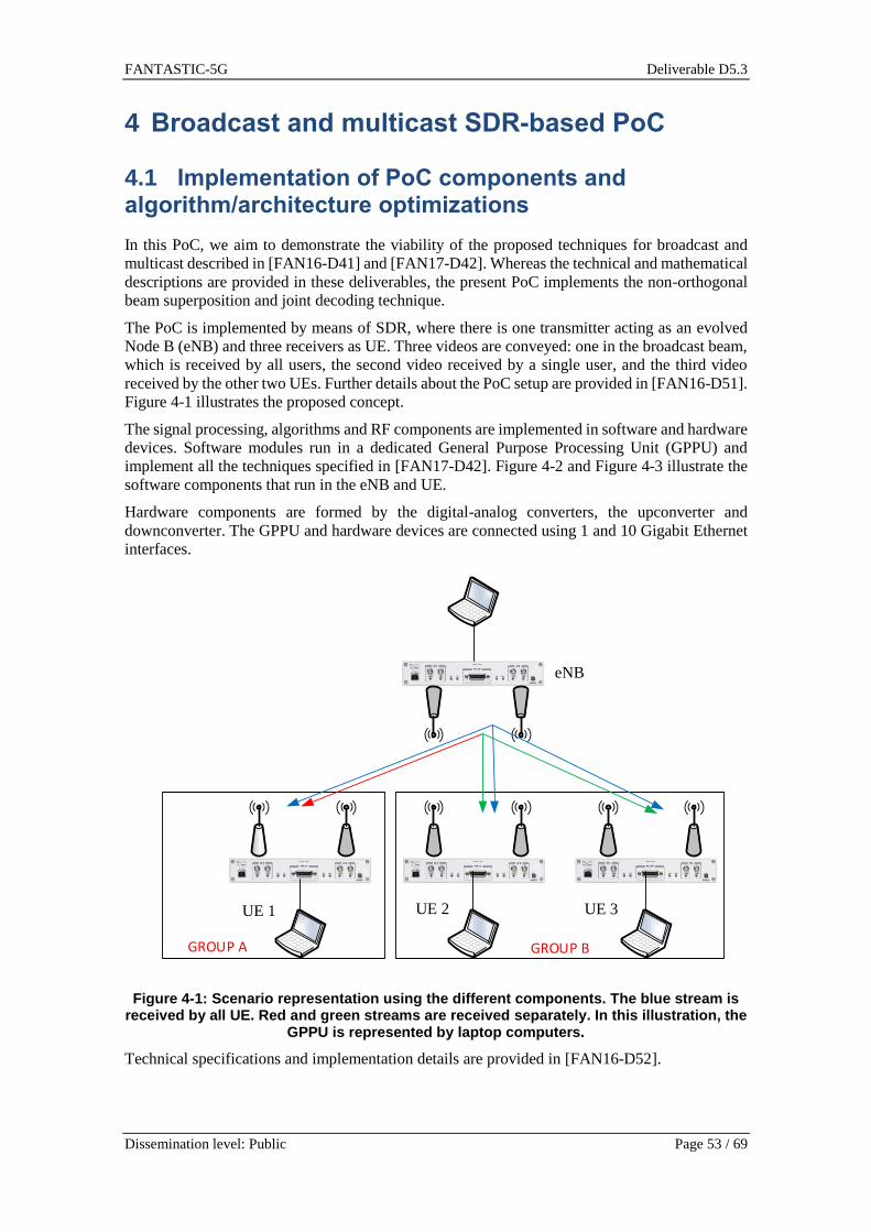
FANTASTIC-5G Deliverable D5.3
Dissemination level: Public Page 53 / 69
4 Broadcast and multicast SDR-based PoC
4.1 Implementation of PoC components and algorithm/architecture optimizations
In this PoC, we aim to demonstrate the viability of the proposed techniques for broadcast and
multicast described in [FAN16-D41] and [FAN17-D42]. Whereas the technical and mathematical
descriptions are provided in these deliverables, the present PoC implements the non-orthogonal
beam superposition and joint decoding technique.
The PoC is implemented by means of SDR, where there is one transmitter acting as an evolved
Node B (eNB) and three receivers as UE. Three videos are conveyed: one in the broadcast beam,
which is received by all users, the second video received by a single user, and the third video
received by the other two UEs. Further details about the PoC setup are provided in [FAN16-D51].
Figure 4-1 illustrates the proposed concept.
The signal processing, algorithms and RF components are implemented in software and hardware
devices. Software modules run in a dedicated General Purpose Processing Unit (GPPU) and
implement all the techniques specified in [FAN17-D42]. Figure 4-2 and Figure 4-3 illustrate the
software components that run in the eNB and UE.
Hardware components are formed by the digital-analog converters, the upconverter and
downconverter. The GPPU and hardware devices are connected using 1 and 10 Gigabit Ethernet
interfaces.
GROUP BGROUP A
Figure 4-1: Scenario representation using the different components. The blue stream is received by all UE. Red and green streams are received separately. In this illustration, the
GPPU is represented by laptop computers.
Technical specifications and implementation details are provided in [FAN16-D52].
eNB
UE 1 UE 2 UE 3

FANTASTIC-5G Deliverable D5.3
Dissemination level: Public Page 54 / 69
Figure 4-2: Transmitter signal processing chain at eNB.
Figure 4-3: Receiver signal processing chain at UE.
The PoC is configured with the relevant radio parameters described in Table 4-1
Table 4-1 Relevant radio parameters.
Frame Type FDD
Prefix Type Normal
Carrier frequency 915 MHz
Bandwidth 5 MHz
Sampling frequency rate 7.68 MS/s
Number of subcarriers 300
Control Channel width 3 symbols
Channel Encoding
Channel Encoding
Channel Encoding
Modulation Mapping
Modulation Mapping
Modulation Mapping
Beam b
BC
Beam b
MC1
Beam b
MC2
Resource Mapping
Resource Mapping
Resource Mapping
Antenna Mapping
OFDM
OFDM
BC
MC1
MC2
Filtering & Interference Mitigation
OFDM Resource
Demapping
Modulation Demapping
Modulation Demapping
Channel Decoding
Channel Decoding
BC
MC
OFDM Resource
Demapping
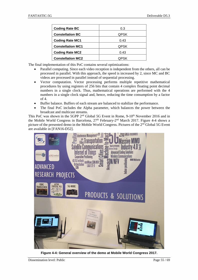
FANTASTIC-5G Deliverable D5.3
Dissemination level: Public Page 55 / 69
Coding Rate BC 0.3
Constellation BC QPSK
Coding Rate MC1 0.43
Constellation MC1 QPSK
Coding Rate MC2 0.43
Constellation MC2 QPSK
The final implementation of this PoC contains several optimizations:
Parallel computing. Since each video reception is independent from the others, all can be
processed in parallel. With this approach, the speed is increased by 2, since MC and BC
videos are processed in parallel instead of sequential processing.
Vector computation. Vector processing performs multiple repetitive mathematical
procedures by using registers of 256 bits that contain 4 complex floating point decimal
numbers in a single clock. Thus, mathematical operations are performed with the 4
numbers in a single clock signal and, hence, reducing the time consumption by a factor
of 4.
Buffer balance. Buffers of each stream are balanced to stabilize the performance.
The final PoC includes the Alpha parameter, which balances the power between the
broadcast and multicast streams.
This PoC was shown in the 5GPP 2nd Global 5G Event in Rome, 9-10th November 2016 and in
the Mobile World Congress in Barcelona, 27th February-2nd March 2017. Figure 4-4 shows a
picture of the presented demo in the Mobile World Congress. Pictures of the 2nd Global 5G Event
are available in [FAN16-D52].
Figure 4-4: General overview of the demo at Mobile World Congress 2017.

FANTASTIC-5G Deliverable D5.3
Dissemination level: Public Page 56 / 69
4.2 PoC final version and evaluation results
4.2.1 Real-time performance
In this section we summarize the PoC real-time performance results. Figure 4-5 is a screenshot of
the transmitter GUI, where the three conveyed videos are displayed in real time. The spectrum
shows the occupied bandwidth at base band level. Finally, the Alpha parameter balances the
power between broadcast and multicast streams. Examining the results of [FAN17-D42], we can
appreciate that the optimal value for Alpha parameter is 0.5 approximately. Thus, we set the Alpha
parameter to 0.5 during the entire transmission. This implies that broadcast and multicast streams
are transmitted with the same power. Note that Alpha parameter can be changed on-the-fly,
balancing the power of each stream. For instance, for Alpha parameter equals to 0, the broadcast
stream obtains the total power and hence, multicast streams are not conveyed. Similarly, for Alpha
parameter equals to 1, multicast streams are conveyed with the maximum power and, thus, the
broadcast stream is not transmitted.
Figure 4-5: Transmitter side, conveying one broadcast and two multicast videos.
Figure 4-6 and Figure 4-7 are screenshots of the receiver GUI part, where useful metrics are
displayed and the channel estimation is plotted. Parameters such as voltage, synchronization
stage, error metrics and throughput are displayed in the main window. Other parameters such as
voltage bias, synchronization estimated parameters, and master block information are displayed
in the first tab. The channel estimation tab displays the frequency response of the two co-channels
and two cross-channels from the 2 × 2 MIMO scheme. The x-axis denotes the subcarrier index,
without the guard bands (5 MHz of bandwidth have 300 subcarriers).

FANTASTIC-5G Deliverable D5.3
Dissemination level: Public Page 57 / 69
The overall performance achieves the maximum throughput, 2216 kbps for each multicast stream
and 680 kbps for the broadcast stream.
Figure 4-6: Receiver side, displaying useful metrics.
Figure 4-7: Receiver side, displaying channel estimation.
4.2.2 Emulated performance
In this section we use the PoC under different scenarios. To analyse the performance in different
scenarios we perform a channel emulation with different channel models. Figure 4-8 illustrates
the environment used to obtain the different metrics. We employ the eNB and UE that we
implemented for this PoC and we emulate different channel conditions.

FANTASTIC-5G Deliverable D5.3
Dissemination level: Public Page 58 / 69
Figure 4-8: Emulation environment.
4.2.2.1 Details of channel emulation
The channel emulation block is a 2 × 2 MIMO, where each channel path models the fast fading
for different channel configurations. We employ ITU EPA and EVA channels, with all profiles
described in [36.104].
To include mobility, we also implemented the Doppler spectrum using the Jakes model, with the
following Doppler spreads at 1.3 GHz carrier frequency:
5 Hz (speed of 2.28 km/h)
70 Hz (speed of 19.89 km/h)
4.2.2.2 Emulation results
Figure 4-9 depicts the Frame Error Rate (FER) of broadcast and multicast streams in the EPA
channel, with a Doppler spread of 5 Hz. This scenario corresponds to a low mobility. Since the
broadcast stream is encoded using a lower coding rate, the FER of broadcast stream is lower
compared with the multicast streams. It is worth to mention that the scheme works in low SNR
regime, even with mobility conditions. The FER is computed counting the number of erroneous
frames divided by the total frames. A frame is considered erroneous if the remainder of CRC is
not zero.
Figure 4-10 illustrates the throughput achieved by broadcast and multicast streams. In this figure,
the broadcast stream obtains lower throughput since it is encoded with lower coding rate. It is
important to remark that all streams achieve the maximum throughput for a 𝑆𝑁𝑅 = −2 𝑑𝐵.
The throughput is computed counting the number of effective bits that are carried within a non-
erroneous subframe per unit time. Note that multicast streams are weighted by a beamformer,
which has an impact into the throughput performance if the user does not lay into the beam
coverage. For this reason, the performances of multicast streams are not the same, even though
both carry the same bitrate.
In the results, the performance of broadcast stream is labeled as BC, which is conveyed with a
bitrate of 680 kbps. MC #1 and MC #2 are the labels of multicast streams, which are conveyed
with a bitrate of 2216 kbps. Each multicast stream is weighted by a different beamformer.

FANTASTIC-5G Deliverable D5.3
Dissemination level: Public Page 59 / 69
Figure 4-9: FER of EPA 5 Hz channel.
Figure 4-10: Throughput of EPA 5 Hz channel.

FANTASTIC-5G Deliverable D5.3
Dissemination level: Public Page 60 / 69
Figure 4-11 depicts the FER in a EVA channel profile of each stream, with a Doppler spread of 5
Hz. Although the Doppler spread is the same compared with the previous scenario, the FER is
increased. This is motivated by the fact that EVA channel profile has more rays with a larger
delay. This is equivalent to a more frequency-selective channel in the frequency domain. The
consequences of this profile is that the accuracy of the channel estimation decreases, since the
degree of channel interpolation is the same. This can be solved by increasing the interpolation
order but at expenses of a computational complexity increase. Due to this, one multicast stream
achieves a higher FER compared with the other multicast stream and broadcast stream.
Figure 4-11: FER of EVA 5 Hz channel.
Figure 4-12 illustrates the throughput in a EVA channel profile. As in the previous figure, the
broadcast stream achieves the maximum throughput from low SNR. However, the second
multicast stream cannot achieve the maximum throughput of 2216 kbps due to the misalignment
between UE and eNB for this beam.
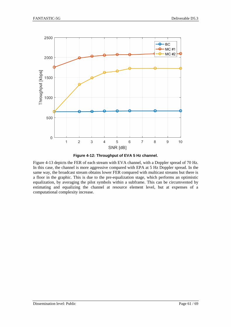
FANTASTIC-5G Deliverable D5.3
Dissemination level: Public Page 61 / 69
Figure 4-12: Throughput of EVA 5 Hz channel.
Figure 4-13 depicts the FER of each stream with EVA channel, with a Doppler spread of 70 Hz.
In this case, the channel is more aggressive compared with EPA at 5 Hz Doppler spread. In the
same way, the broadcast stream obtains lower FER compared with multicast streams but there is
a floor in the graphic. This is due to the pre-equalization stage, which performs an optimistic
equalization, by averaging the pilot symbols within a subframe. This can be circumvented by
estimating and equalizing the channel at resource element level, but at expenses of a
computational complexity increase.

FANTASTIC-5G Deliverable D5.3
Dissemination level: Public Page 62 / 69
Figure 4-13: FER of EVA 70 Hz channel.
Figure 4-14 illustrates the throughput with the EVA channel, with a 70 Hz of Doppler spread. In
contrast to the EPA channel with a 5 Hz Doppler spread, not all streams achieve the maximum
throughput. As explained above, the channel becomes more aggressive and the pre-equalization
stage is determinant in the performance.

FANTASTIC-5G Deliverable D5.3
Dissemination level: Public Page 63 / 69
Figure 4-14: Throughput of EVA 70 Hz channel.
4.2.2.3 LTE benchmark
In this section we provide different FER and throughput metrics of LTE Multimedia Broadcast
Multimedia Service (MBMS) specifications. Note that in LTE there is neither physical layer
multicast nor beamforming in MBMS frames. Thus, we emulate a standard compliant MBMS
frame, with the same coding rates (CR) of the previous broadcast and multicast streams (CR=0.3
and CR=0.43), providing bitrates of 680 kbps and 2260 kbps.
We compare the proposed technique with LTE benchmark in terms of aggregated throughput,
which is computed by computing the total throughput served by the cell. Figure 4-15 and Figure
4-16 illustrate the aggregated throughput corresponding to the EPA and EVA profiles, with a
Doppler spread of 5 Hz. As aforementioned, the proposed technique is able to multiplex and serve
different streams, increasing the aggregated throughput without requiring additional power.
Whereas legacy LTE MBMS can serve a single stream, our proposed technique multiplex several
streams intended to different users by sharing the same frequency-time resources.

FANTASTIC-5G Deliverable D5.3
Dissemination level: Public Page 64 / 69
Figure 4-15: Aggregated throughput of the proposed technique compared with the LTE MBMS channel, corresponding to the EPA channel profile, with a Doppler spread of 5 Hz.
Figure 4-16: Aggregated throughput of the proposed technique compared with the LTE MBMS channel, corresponding to the EVA channel profile, with a Doppler spread of 5 Hz.

FANTASTIC-5G Deliverable D5.3
Dissemination level: Public Page 65 / 69
Although the comparison of the proposed technique with LTE benchmark in terms of FER is not
straightforward, we provide the FER metrics of the LTE benchmark, for the two different coding
rates. Figure 4-17 and Figure 4-18 depict the FER achieved by the LTE MBMS channel, with the
same proposed coding rates for EPA and EVA channel profiles, with a Doppler spread of 5 Hz.
As aforementioned, EVA is more aggressive compared with EPA profile, which generates a
higher FER. Compared with Figure 4-9 and Figure 4-11 we can appreciate that the FER is similar,
but taking into account that the LTE MBMS channel carries a single stream, whereas the proposed
solution carries three independent streams.
Figure 4-17: FER of broadcast channel at the same coding rate of proposed technique corresponding to the EPA channel profile, with a Doppler spread of 5 Hz.

FANTASTIC-5G Deliverable D5.3
Dissemination level: Public Page 66 / 69
Figure 4-18: FER of broadcast channel at the same coding rate of proposed technique corresponding to the EVA channel profile, with a Doppler spread of 5 Hz.

FANTASTIC-5G Deliverable D5.3
Dissemination level: Public Page 67 / 69
5 Conclusions
This deliverable reviewed the scenarios and basic components and building blocks of the different
PoCs and presented the final integrated platforms. Additionally, the deliverable provided and
discussed the performance evaluation results of the different PoCs developed in FANTASTIC-
5G. The proposed implementations are grouped and presented in three main categories: (1)
Prototyping for post-OFDM waveforms, (2) Evaluation of waveform coexistence aspects, and (3)
Development of a SDR-based demonstration for broadcast and multicast transmission.
In this context, FBMC, FC-OFDM and UF-OFDM low-complexity transceivers have been
implemented and evaluated in a real-time hardware PoC platform in MMC, V2X and MCC
scenarios. Outstanding results are achieved compared to the state-of-the-art technique Cyclic
Prefix (CP)-OFDM in terms of robustness against channel impairments and suitability for low
latency and reliable communications.
BF-OFDM, that combines CP-OFDM and filter bank as in FBMC to overcome the challenges of
adapting the FBMC waveform to MIMO system, is implemented. The compatibility with MIMO
is demonstrated and the good frequency localization properties of BF-OFDM are verified.
P-OFDM waveform is implemented and tested for both asynchronous TA-free uplink low latency
transmission and single link real time evaluation scenarios. In both scenarios, P-OFDM showed
superior performance compared to that of the OFDM. Additional high velocity scenario is
performed with indoor test bed and channel emulator.
Towards fulfilling low latency transmission requirement of mission-critical communication
services, a parameterized-OFDM transceiver has been developed and implemented on a DSP-
based SDR platform. In the proposed implementation, the radio frame structure is latency scalable
and can achieve end-to-end latencies below 1 ms.
Considering the evaluation of waveform coexistence aspects between different waveforms in
adjacent bands, the coexistence aspects for CP-OFDM, UF-OFDM and FBMC/OQAM
waveforms are demonstrated under realistic hardware impairments where the performance is
measured in terms of error-vector magnitude (EVM). Different settings of time delay and guard
carriers between the user of interest and the asynchronous interferers are considered.
The joint broadcast and multicast transmission PoC implements, by means of SDR, the non-
orthogonal beam superposition and joint decoding techniques. A hardware/software environment
based on USRP nodes for UE and eNB is developed. All the signal processing blocks are
implemented in software with all the necessary optimizations to reduce the implementation
complexity. Real time evaluation is performed to demonstrate the scheme ability to use the entire
available bandwidth to transmit several multimedia streams sharing the same frequency and time
resources, and to use the spatial dimension to design the coverage of each stream, distinguishing
between broadcast and multicast transmissions. Additionally, performance evaluation with
different emulated channels are performed and compared with LTE benchmark.
Finally, it is worth mentioning that the aforementioned PoCs have been presented in several
dissemination events such as EuCNC 2016, ETSI Workshop 2016, ISTC 2016, 2nd Global 5G
Event 2016, MWC 2017, ICC 2017, and EuCNC 2017.

FANTASTIC-5G Deliverable D5.3
Dissemination level: Public Page 68 / 69
6 References
[36.104] 3GPP TS 36.104, Base Station (BS) radio transmission and reception
[36.888] 3GPP TR 36.888, “Study on provision of low-cost Machine-Type
Communications (MTC) User Equipments (UEs) based on LTE (Release 12)”,
June 2013.
[BIN90] Bingham, John AC. "Multicarrier modulation for data transmission: An idea
whose time has come." IEEE Communications magazine 28.5 (1990): 5-14.
[CSW14] Chen, Yejian, Frank Schaich, and Thorsten Wild. "Multiple access and
waveforms for 5G: IDMA and universal filtered multi-carrier." Vehicular
Technology Conference (VTC Spring), 2014 IEEE 79th. IEEE, 2014.
[DS11] Y. Dandach and P. Siohan, “FBMC/OQAM Modulators with Half Complexity”,
in Proc. of the IEEE Global Telecommunications Conference (GLOBECOM),
Dec. 2011.
[EWH17] S. Eldessoki, D. Wieruch, B. Holfeld "Impact of Waveforms on Coexistence of
Mixed Numerologies in 5G URLLC Networks", Proceedings of the 21st
International ITG Workshop on Smart Antennas (WSA 2017). VDE, 2017.
[FAN16-D31] FANTASTIC-5G, Deliverable D3.1 “Preliminary results for multi-service
support in link solution adaptation”, June 2016.
[FAN16-IR32] FANTASTIC-5G, Internal Report IR3.2 “Internal Report on the holistic link
solution adaptation”, November 2016.
[FAN16-D41] FANTASTIC-5G, Public Deliverable D4.1 Technical Results for Service
Specific Multi-Node/Multi-Antenna Solutions, June 2016.
[FAN17-D42] FANTASTIC-5G, Public Deliverable D4.2 Final results for the flexible 5G air
interface multinode/multi-antenna solution, May 2017.
[FAN16-D51] FANTASTIC-5G, Deliverable D5.1 “Identification of the PoC scenarios”, June
2016.
[FAN16-D52] FANTASTIC-5G, Deliverable D5.2 “PoC intermediate version and component
implementation”, Dec. 2016.
[Hir81] B. Hirosaki, “An Orthogonally Multiplexed QAM System Using the Discrete
Fourier Transform”, IEEE Trans. on communications, vol. com-29, no. 7, July
1981.
[LGS14] H. Lin, et al., “Impact of time and carrier frequency offsets on the FBMC/OQAM
modulation scheme”, Signal Processing (2014).
[Mar98] Martin, Kenneth W. "Small side-lobe filter design for multitone data-
communication applications." IEEE Transactions on Circuits and Systems II:
Analog and Digital Signal Processing 45.8 (1998): 1155-1161.
[MZS16] M. Matthe, D. Zhang, F. Schaich, T. Wild, R. Ahmed, and G. Fettweis, “A
reduced complexity time-domain transmitter for UF-OFDM,” in 2016 IEEE 83rd
Vehicular Technology Conference (VTC Spring), May 2016, pp. 1–5.
[NAB15] J. Nadal, C. Adbel Nour, and A. Baghdadi, “Low-complexity pipelined archi
tecture for FBMC/OQAM transmitter,” IEEE Transactions on Circuits and
Systems II: Express Briefs, no. 99, 2015.
[PMW+16] J. Pilz, M. Mehlhose, T. Wirth, D. Wieruch, B. Holfeld, and T. Haustein, “A
Tactile Internet Demonstration: 1ms Ultra Low Delay for Wireless
Communications towards 5G,” in IEEE INFOCOM Live/Video Demonstration,
April 2016, pp. 21–22.
[PSY+15] ICT--‐317669 METIS project, “Proposed solutions for new radio access,”
Deliverable D2.4, Feb. 2015.
https://www.metis2020.com/documents/deliverables/

FANTASTIC-5G Deliverable D5.3
Dissemination level: Public Page 69 / 69
[Sal67] B. Saltzberg, “Performance of an Efficient Parallel Data Transmission System”,
IEEE Transactions on Communication Technology, vol. 15, no. 6, pp. 805–811,
December 1967.
[SZL+14] Schellmann, Malte, et al. "FBMC-based air interface for 5G mobile: Challenges
and proposed solutions." Cognitive Radio Oriented Wireless Networks and
Communications (CROWNCOM), 2014 9th International Conference on. IEEE,
2014.
[VBH09] Viholainen, Ari, Maurice Bellanger, and Mathieu Huchard. "Prototype filter and
structure optimization." website: www. ict-phydyas. org: Document D 5 (2009).
[VWS+13] V. Vakilian, T. Wild, F. Schaich, S. ten Brink, and J. F. Frigon, “Universal filtered
multi-carrier technique for wireless systems beyond LTE,” in 2013 IEEE
Globecom Workshops, Dec 2013, pp. 223–228.
[WHM+16] T. Wirth, B. Holfeld, M. Mehlhose, J. Pilz, D. Wieruch, “5G New Radio and
Ultra Low Latency Applications: A PHY Implementation Perspective,” in Proc.
of Asilomar, Nov. 2016
[WMP+15] T. Wirth, M. Mehlhose, J. Pilz, R. Lindstedt, D. Wieruch, B. Holfeld, and T.
Haustein, “An Advanced Hardware Platform to Verify 5G Wireless
Communication Concepts,” in Proc. of IEEE VTC-Spring, May 2015, pp. 1–5.
[WS15] T. Wild and F. Schaich, “A reduced complexity transmitter for UF-OFDM,” in
2015 IEEE 81st Vehicular Technology Conference (VTC Spring), May 2015, pp.
1–6.