flex array 12 version 1.1
TRANSCRIPT
8/3/2019 Flex Array 12 Version 1.1
http://slidepdf.com/reader/full/flex-array-12-version-11 1/102
FlexArrayFlexArrayFlexArrayFlexArray----12121212
Disk EnclosureDisk EnclosureDisk EnclosureDisk Enclosure
User’s GuideUser’s GuideUser’s GuideUser’s Guide

8/3/2019 Flex Array 12 Version 1.1
http://slidepdf.com/reader/full/flex-array-12-version-11 2/102
8/3/2019 Flex Array 12 Version 1.1
http://slidepdf.com/reader/full/flex-array-12-version-11 3/102
FlexArray-12 Disk EnclosureUser’s GuideVersion 1.1
i
C O R P O R A T I O N
TABLE OF CONTENTS
1. Preface................................................................................. 1Disclaimer....................................................................... 1Trademarks .................................................................... 1Modifications................................................................... 2FCC Radio Frequency Interference Statement ............... 2FCC Booklet Information................................................. 3Shielded Cables ............................................................. 3Compliances................................................................... 3IMPORTANT SAFETY INSTRUCTIONS ........................ 4General Precautions and Electrical Considerations ........ 4Cleaning Instructions ...................................................... 6
2. Features............................................................................... 7FlexArray-12 General Overview...................................... 7RAIDmanLITE Software.................................................. 9EAM Configuration via Serial Tool .................................. 9Environment Array Manager (EAM)...............................10LCD Control Panel.........................................................10LCD Control Panel Diagram ..........................................11
LCD Panel Tables..........................................................12Main Menu Icon Table ...................................................12Sub Menu Icon Table.....................................................12Drive Status LEDs .........................................................13Fan Monitoring...............................................................13Enclosure Temperature Monitoring................................13Power Subsystem Monitoring ........................................13Communications Ports...................................................14SCSI Connectors...........................................................14Event Notification...........................................................14
3. Hardware Installation ..................................................15Quick Install Checklist....................................................15
Safety Precautions & Unpacking Procedures.................16Hardware & Software Installation Requirements............17Additional Installation Requirements..............................17FlexArray-12 Front View................................................18
8/3/2019 Flex Array 12 Version 1.1
http://slidepdf.com/reader/full/flex-array-12-version-11 4/102
FlexArray-12 Disk EnclosureUser’s GuideVersion 1.1
ii
FlexArray-12 Rear View.................................................19FlexArray-12 Side Views................................................20FlexArray-12 Rack Mount Version .................................21Drive Order FlexArray-12 Rack and Tower Versions .....22SCSI ID Settings............................................................23To Install or Replace a Disk Drive..................................26Power Supply Unit Lock.................................................28To Unlock a Power Supply Unit .....................................28To Lock a Power Supply Unit.........................................31
Cable Connections for One Channel Single EnclosureConfiguration .................................................................32One Channel Single Enclosure Configuration................33Cable Connections for Two Channel Single EnclosureConfiguration .................................................................34Two Channel Single Enclosure Configuration................35Cable Connections for Two Channel Multiple EnclosureConfiguration .................................................................36Two Channel Multiple Enclosure Configuration..............37
4. Enclosure Configuration.....................................................38Quick Configuration Checklist........................................39
LCD Control Panel Diagram ..........................................40LCD Panel Tables..........................................................41Main Menu Icon Table ...................................................41Sub Menu Icon Table.....................................................41Alarm Reset/ Error Log..................................................42Select (RAIDMan Activity)..............................................42Enter (Configuration) .....................................................42To Quiet the Error Log Alarm.........................................43To Initiate the LCD Configuration Menu.........................44To Set an Enclosure ID..................................................46To Enable Temperature Sensor Settings.......................48To Change Buzzer Settings...........................................51
Hard Addresses.............................................................52To Configure Expansion Enclosures..............................52
5. EAM Configuration using Serial Tool ...............................53Cable Connections ........................................................53
8/3/2019 Flex Array 12 Version 1.1
http://slidepdf.com/reader/full/flex-array-12-version-11 5/102
FlexArray-12 Disk EnclosureUser’s GuideVersion 1.1
iii
C O R P O R A T I O N
To Install Serial Tool on.................................................54Windows 95/98 and Windows NT ..................................54To Run EAM Configuration Serial Tool ..........................55Enclosure Configuration.................................................57To Configure an Enclosure ............................................58To Upgrade the Flash....................................................60To Accept the Existing Configuration Settings ...............62
6. RAIDmanLITE Software .....................................................64
RAIDmanLITE System Requirements............................64To Connect Cables........................................................65To Install RAIDmanLITE on Windows95/98 and WindowsNT .................................................................................65To Run RAIDmanLITE...................................................66Main Control Panel ........................................................66Enclosures Display ........................................................67Enclosure Temperature Display.....................................67Alarm Status and Log Displays......................................68Action Buttons ...............................................................69Enclosure Configuration Functions ................................69To Configure an Enclosures Sensors.............................70
To Set or Modify the System Password .........................71Define Alerts..................................................................72MS Mail .........................................................................73MHS ..............................................................................74NetWare Broadcast .......................................................75Pager.............................................................................76UNIX Broadcast.............................................................77
7. Troubleshooting.................................................................79Setup Issues Action List.................................................80Enclosure ID Problems..................................................81Power-up Problems.......................................................82Set-up Problems............................................................83
LCD Error Number Table...............................................83Enclosure or Drive Errors...............................................85Drive Failure ..................................................................85What to do if a Drive Fails..............................................85
8/3/2019 Flex Array 12 Version 1.1
http://slidepdf.com/reader/full/flex-array-12-version-11 6/102
FlexArray-12 Disk EnclosureUser’s GuideVersion 1.1
iv
Raidtec Technical Support.............................................86
Glossary...................................................................................87

8/3/2019 Flex Array 12 Version 1.1
http://slidepdf.com/reader/full/flex-array-12-version-11 7/102
FlexArray-12 Disk EnclosureUser’s GuideVersion 1.1
1
C O R P O R A T I O N
1. PREFACE Disclaimer
The information in this document is subject to change without noticeand should not be construed as a commitment by Raidtec Corporationor its agents. Raidtec Corporation assumes no responsibility for anyerrors that may appear in this document except in so far as alterationsmay be made subsequent to receiving written indication of the
information concerned.
The product description in this document is intended solely for use inoperation, installation and maintenance of the Raidtec FlexArray-12 Disk Enclosure. Use of this document for all other purposes, withoutprior written approval from Raidtec Corporation is prohibited.
Copyright © 1999Raidtec Corporation400 Overlook Business ParkBldg. 12, 1360 Union Hill RoadAlpharetta, GA 30004-7759andCastle RoadLittle Island Industrial EstateCork, Ireland
All rights reserved. No part of this document may be reproduced,photocopied, stored on a retrieval system, or transmitted withoutexpress permission of Raidtec Corporation.
Trademarks
Raidtec, RAIDmanLITE , and FlexArray are all trademarks of RaidtecCorporation. All other names, brands, products and services aretrademarks or registered trademarks of their respective companies.
8/3/2019 Flex Array 12 Version 1.1
http://slidepdf.com/reader/full/flex-array-12-version-11 8/102
FlexArray-12 Disk EnclosureUser’s GuideVersion 1.1
2
Modifications
Changes or modifications not expressly approved by RaidtecCorporation could void the user’s authorization to operate theequipment.
FCC Radio Frequency Interference Statement
This equipment generates, uses, and can radiate radio frequencyenergy. If not installed and used in strict accordance with themanufacturer’s instructions, it may cause interference to radio andtelevision reception. The limits are designed to provide reasonableprotection against interference in a residential installation. However,there is no guarantee that interference will not occur in a particularinstallation.
NOTE: This equipment has been tested and found to comply with the limits for a Class A computing device in accordance with the specifications in Subpart B of Part 15 of FCC rules.
If this equipment does cause interference to radio or televisionreception, users are encouraged to try one or more of the followingcorrective measures:
• Reorient the receiving antenna.
• Relocate the computer with respect to the receiver.
• Move the computer away from the receiver.
• Plug the computer into a different outlet so that computer andreceiver are on different branch circuits.
• Consult the dealer or an experienced radio/television technicianfor additional suggestions.

8/3/2019 Flex Array 12 Version 1.1
http://slidepdf.com/reader/full/flex-array-12-version-11 9/102
FlexArray-12 Disk EnclosureUser’s GuideVersion 1.1
3
C O R P O R A T I O N
FCC Booklet Information
The following booklet, prepared by the Federal CommunicationsCommission, may also be helpful in resolving interference issues:How to Identify and Resolve Radio/TV Interference Problems.This booklet is available from the U.S. Government Printing Office,Washington, DC 20401, Stock No. 004-000-00345-4.
Shielded Cables
SHEILDED INTERFERENCE CABLE(S) MUST BE USEDACCORDING TO FCC 15.838D
Compliances
CANADA:
This digital apparatus does not exceed the Class A limits for noiseemissions from digital apparatus set out in the Radio InterferenceRegulations of the Canadian Department of Communications.
Le present appareil numerique n’emet pas de bruits radioelectriquesdepasssant les limites applicables aux appareil numerique de la class Aenoncees par les Reglements sur les brouilages radioelectriques emispar le Ministere des Communications du Canada.
EUROPE:
This product has been investigated in accordance to UL 1950.
This product was designed, developed, and manufactured
under an NSAI registered I.S. EN ISO 9001 quality system.
This device complies with EU EMC Directive 89/336/EEC andwas assessed to the requirements of the following:EN 55022-1994+A1, A2 CISPR 22 Class A.EN 50082-1-1997 (EN 61000-4-2,3,4,5,6,11).

8/3/2019 Flex Array 12 Version 1.1
http://slidepdf.com/reader/full/flex-array-12-version-11 10/102
FlexArray-12 Disk EnclosureUser’s GuideVersion 1.1
4
IMPORTANT SAFETY INSTRUCTIONS
General Precautions and Electrical Considerations
• Read all these instructions before setting up and using your system!
• Follow all warnings and instructions noted on the computer and inthe operating instructions.
• Save these instructions for future reference.
• Use of a non-interruptible power supply is strongly recommended.
• Do not set up or use this device near water. Electrical shock anddamage may occur if water shorts out high voltage parts.
• Do not block the enclosure vents or place this device in a built-ininstallation unless proper ventilation is provided. Blockingenclosure vent could cause installed components to overheat andoperate unreliably. Avoid setting the device on a bed, sofa, carpet,pillow or other soft surfaces that can cover the enclosure vents.
• Never set the device on a radiator, heat register, or other heatsource.
• Never insert foreign objects into the enclosure slots. Fire, electricalshock, and/or damage may occur if such objects short out highvoltage parts.
• Operate the device using the correct type of AC power source, asspecified on the label (typically, 115V/230V in the US and Canada;50Hz/60Hz in the UK and Europe).
• Plug the power cord into a properly grounded electrical outlet to
prevent electrical shock.
• Do not use adapter plugs or remove the grounding prong.
8/3/2019 Flex Array 12 Version 1.1
http://slidepdf.com/reader/full/flex-array-12-version-11 11/102
FlexArray-12 Disk EnclosureUser’s GuideVersion 1.1
5
C O R P O R A T I O N
• Replace any obsolete outlet. If you use an extension cord with thesystem, use a 3-wire extension cord and make sure that theextension cord’s ampere rating is sufficient to handle the load of allthe equipment plugged into it.
• Use an approved surge suppresser to protect the equipment fromerratic electricity.
• Install new or replace failed disk drives with UL listed or ULrecognized disk drives ONLY.
• Check that the total load of all devices attached to one cord or oneoutlet never exceeds 15 amperes. The wattage rating for mostdevices is listed on the label for the product.
• Do not set any object on the power cord. Situate the power cordaway from traffic areas so it will not be stepped on or tripped over.
• Prevent static electricity from permanently damaging yourelectronic components.
• Handle components and cards with care. Avoid touchingcomponents and contacts on cards. If possible, hold the card by itsedges or by its metal mounting bracket.
• Do not attempt to service this device yourself except as explainedin the manual.
Please ensure the following precautions are observed when rackmounting the equipment:
• The maximum operating ambient temperature is 40˚ (Celsius).
• The rear of the unit should have at least one foot of clearance fromany other objects for ventilation.
• The unit should be powered from a dedicated branch circuit toprevent circuit overloading.

8/3/2019 Flex Array 12 Version 1.1
http://slidepdf.com/reader/full/flex-array-12-version-11 12/102
FlexArray-12 Disk EnclosureUser’s GuideVersion 1.1
6
• The safety earth connection is provided by power supply cord. Thepower supply cord should be connected to an outlet that isgrounded in accordance with the National Electric Code (NEC).
Contact service personnel for assistance if:
• A power cable or plug is frayed or damaged.
• The device is exposed to rain or water, or liquid has been spilled
into it.
• The device is dropped or the enclosure is damaged.
• The device does not operate normally when the operatinginstructions are followed.
Cleaning Instructions
• Turn off the equipment and unplug it from the electrical outlet beforecleaning.
• Use a slightly damp cloth for cleaning. Never apply liquid or aerosol
cleaners directly to computing devices.
• If the device gets wet, unplug all system power cables and contactRaidtec Technical Support for assistance.

8/3/2019 Flex Array 12 Version 1.1
http://slidepdf.com/reader/full/flex-array-12-version-11 13/102
8/3/2019 Flex Array 12 Version 1.1
http://slidepdf.com/reader/full/flex-array-12-version-11 14/102
FlexArray-12 Disk EnclosureUser’s GuideVersion 1.1
8
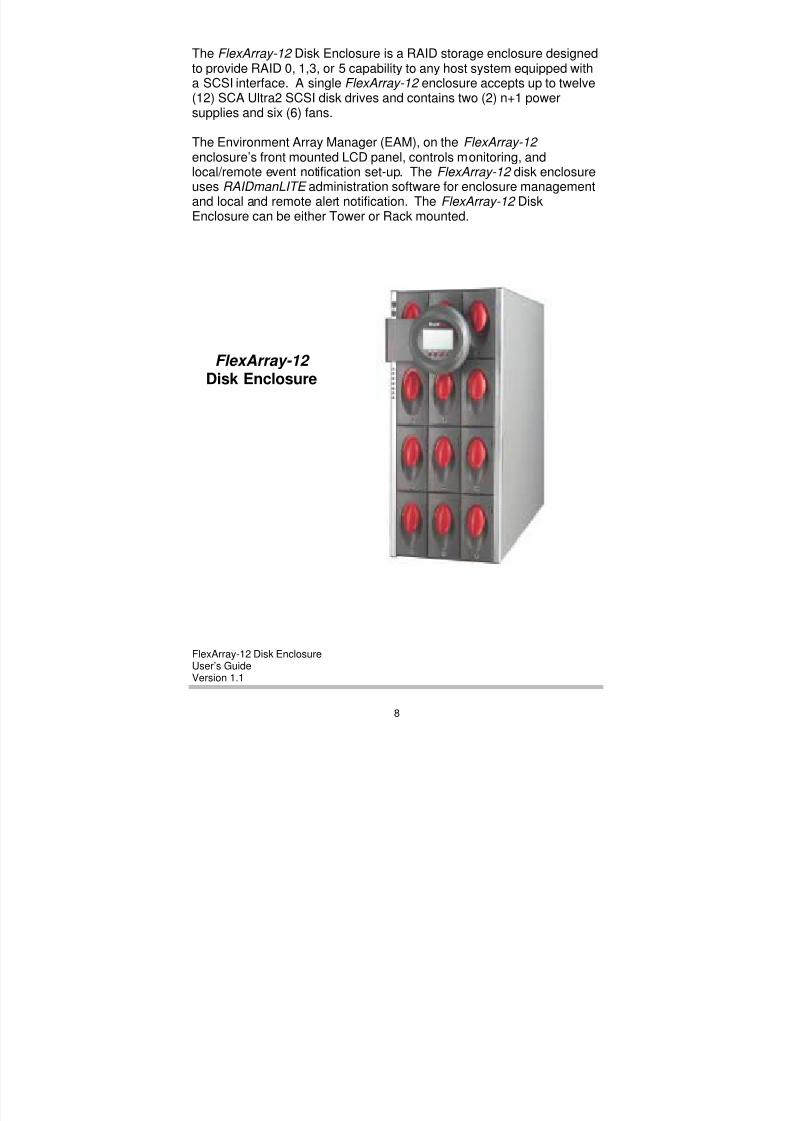
The FlexArray-12 Disk Enclosure is a RAID storage enclosure designedto provide RAID 0, 1,3, or 5 capability to any host system equipped witha SCSI interface. A single FlexArray-12 enclosure accepts up to twelve(12) SCA Ultra2 SCSI disk drives and contains two (2) n+1 powersupplies and six (6) fans.
The Environment Array Manager (EAM), on the FlexArray-12 enclosure’s front mounted LCD panel, controls monitoring, andlocal/remote event notification set-up. The FlexArray-12 disk enclosureuses RAIDmanLITE administration software for enclosure managementand local and remote alert notification. The FlexArray-12 DiskEnclosure can be either Tower or Rack mounted.
FlexArray-12 Disk Enclosure
8/3/2019 Flex Array 12 Version 1.1
http://slidepdf.com/reader/full/flex-array-12-version-11 15/102
FlexArray-12 Disk EnclosureUser’s GuideVersion 1.1
9
C O R P O R A T I O N
RAIDmanLITE Software
The RAIDmanLITE administration software provides a 32-bit, Windowscompatible, GUI for initialization, administration, and event notificationof all aspects of the FlexArray-12 disk enclosure. This utility is availablefor operation in Windows 95/98 and Windows NT environments.
RAIDmanLITE complete graphical interface features include:
• Environment monitoring.• Temperature sensor configuration.
• Local and remote alarm administration.
• Password protection for key configuration and diagnostic functions.
EAM Configuration via Serial Tool
In instances where FlexArray-12 enclosures do not have LCD panels,this software tool allows users to:
• Configure FlexArray-12 enclosures IDs.
• Enable temperature sensor.
•Set temperature thresholds.
• Upgrade Flash.
The Upgrade Flash option on EAM Configuration via Serial Tool, allowsusers to update the flash with a new version of EAM firmware codewhen necessary.
This utility software is available for operation in both Windows 95/98and Windows NT and can also be used under any terminal emulationsoftware.
8/3/2019 Flex Array 12 Version 1.1
http://slidepdf.com/reader/full/flex-array-12-version-11 16/102
FlexArray-12 Disk EnclosureUser’s GuideVersion 1.1
10
Environment Array Manager (EAM)
The FlexArray-12 Environment Array Manager (EAM) monitorstemperature, fans, power supplies, disk presence, and disk fault status.The EAM outputs appropriate status information in the form of driveLED indicators, LCD panel, and/or communication messages via theserial port to local or remote systems and applications such as, theRAIDmanLITE software.
LCD Control Panel
Users can operate the LCD display panel on the front of the enclosureto display information about enclosure ID, enclosure temperature,power, and enclosure monitoring and alerts.
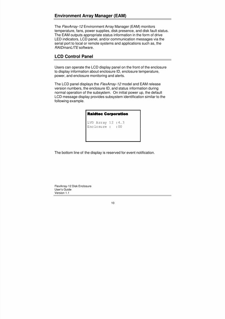
The LCD panel displays the FlexArray-12 model and EAM releaseversion numbers, the enclosure ID, and status information duringnormal operation of the subsystem. On initial power up, the defaultLCD message display provides subsystem identification similar to thefollowing example.
The bottom line of the display is reserved for event notification.
Raidtec CorporationRaidtec CorporationRaidtec CorporationRaidtec Corporation
LVD Array 12 :4.3
Enclosure : :00
8/3/2019 Flex Array 12 Version 1.1
http://slidepdf.com/reader/full/flex-array-12-version-11 17/102
FlexArray-12 Disk EnclosureUser’s GuideVersion 1.1
11
C O R P O R A T I O N
LCD Control Panel Diagram
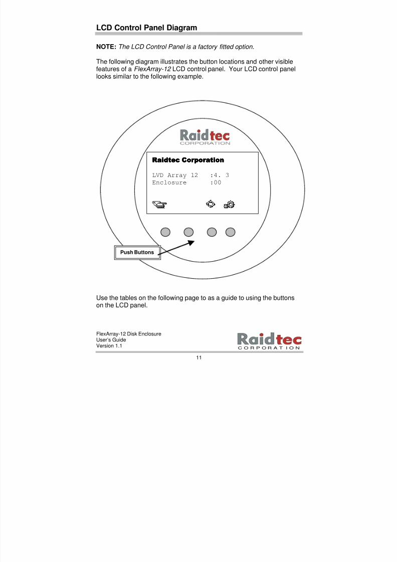
NOTE: The LCD Control Panel is a factory fitted option.
The following diagram illustrates the button locations and other visiblefeatures of a FlexArray-12 LCD control panel. Your LCD control panellooks similar to the following example.
Use the tables on the following page to as a guide to using the buttonson the LCD panel.
Raidtec CorporationRaidtec CorporationRaidtec CorporationRaidtec Corporation
LVD Array 12 :4. 3
Enclosure :00
Push Buttons
8/3/2019 Flex Array 12 Version 1.1
http://slidepdf.com/reader/full/flex-array-12-version-11 18/102
FlexArray-12 Disk EnclosureUser’s GuideVersion 1.1
12
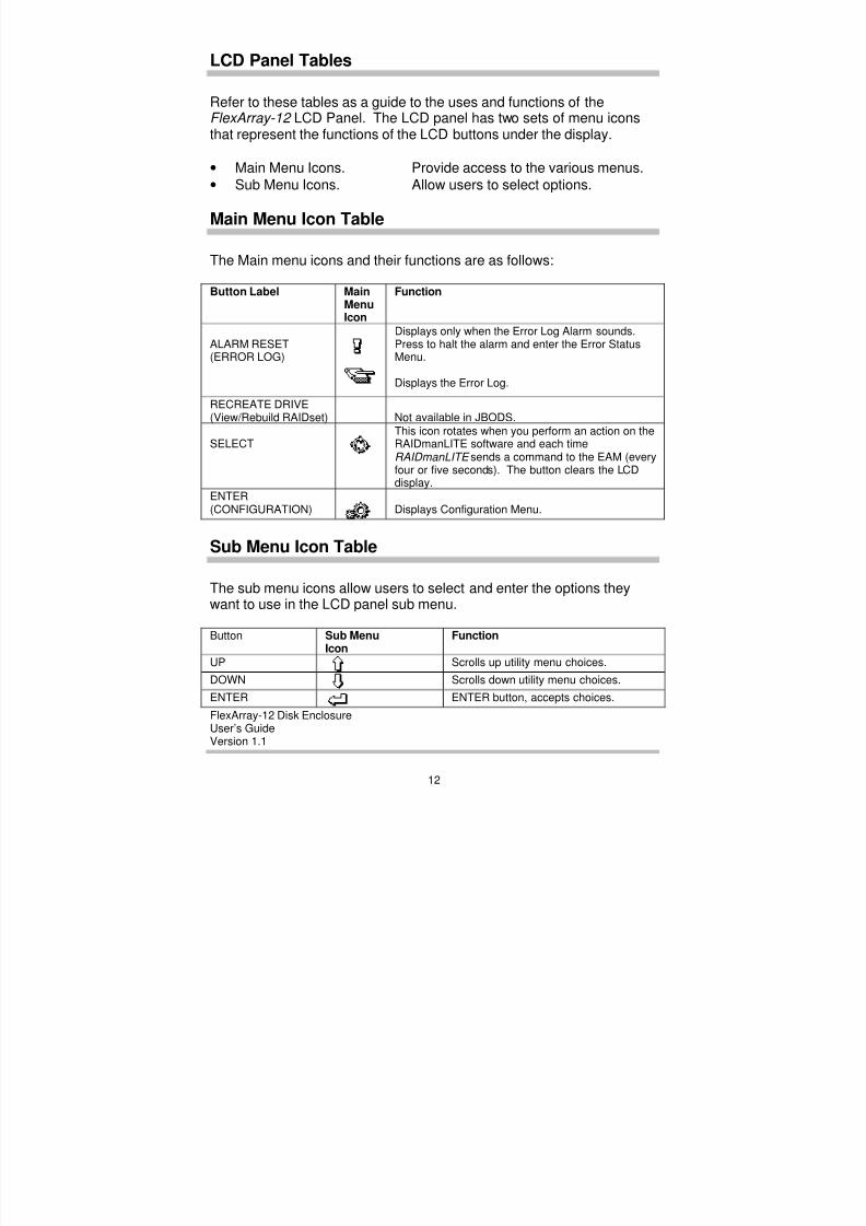
LCD Panel Tables
Refer to these tables as a guide to the uses and functions of theFlexArray-12 LCD Panel. The LCD panel has two sets of menu iconsthat represent the functions of the LCD buttons under the display.
• Main Menu Icons. Provide access to the various menus.
• Sub Menu Icons. Allow users to select options.
Main Menu Icon Table
The Main menu icons and their functions are as follows:
Button Label MainMenuIcon
Function
ALARM RESET(ERROR LOG)
Displays only when the Error Log Alarm sounds.Press to halt the alarm and enter the Error StatusMenu.
Displays the Error Log.
RECREATE DRIVE(View/Rebuild RAIDset) Not available in JBODS.
SELECTThis icon rotates when you perform an action on theRAIDmanLITE software and each timeRAIDmanLITE sends a command to the EAM (everyfour or five seconds). The button clears the LCDdisplay.
ENTER(CONFIGURATION) Displays Configuration Menu.
Sub Menu Icon Table
The sub menu icons allow users to select and enter the options theywant to use in the LCD panel sub menu.
Button Sub MenuIcon
Function
UP Scrolls up utility menu choices.
DOWN Scrolls down utility menu choices.
ENTER ENTER button, accepts choices.
8/3/2019 Flex Array 12 Version 1.1
http://slidepdf.com/reader/full/flex-array-12-version-11 19/102
FlexArray-12 Disk EnclosureUser’s GuideVersion 1.1
13
C O R P O R A T I O N
Drive Status LEDs
Each drive on the FlexArray-12 has three (3) associated LED indicatorsvisible from the front of the enclosure. The following LED colorindicators display each individual drive’s status.
• Drive Error Red.
• Drive Activity Yellow.
• Drive Power Green.
Fan Monitoring
Six (6) rear mounted, fans provide cooling for the enclosure. Thesefans are attached to the fan backplane. This monitors the fans for anyabnormal current variations and flags a fan failure via the ServiceChannel to the EAM.
Enclosure Temperature Monitoring
One (1) temperature monitor port is present by default, mounted on theEAM controller and appropriate thresholds may be set via the
Configuration Menu. When the temperature exceeds the threshold, theEAM flags the alerts to the LCD panel and the RS-232 port, to theRAIDmanLITE software if configured.
Power Subsystem Monitoring
The FlexArray-12 power subsystem consists of two (2) PSUs (PowerSupply Units) in an N+1 fault tolerant arrangement. Power distributionis via the power subsystem backplane. Any PSU failure results inflashing of the appropriate front LCD panel LED, and an alert being sentthrough the EAM to the Error Log Alarm on the LCD control panel.

8/3/2019 Flex Array 12 Version 1.1
http://slidepdf.com/reader/full/flex-array-12-version-11 20/102
FlexArray-12 Disk EnclosureUser’s GuideVersion 1.1
14
Communications Ports
You will find positions for four (4) DB9 ports on the rear of theFlexArray-12 enclosure labeled SER 1, SER 2, SER 3 and SER 4respectively.
• SER 1 is blank on the FlexArray-12 .
• SER 2 provides an RS 232 link for configuration and event
notification via the RAIDmanLITE software (and the EAMConfiguration using Serial Tool utility software).
• SER 3 and SER 4 use RS 485 multi-drop cables for multi-enclosurecommunication.
NOTE: In instances where the FlexArray-12 expansion enclosures do not have LCD panels you can use SER 2 to connect to the EAM Configuration using Serial Tool software to configure your enclosure IDs. (See Chapter 5. EAM Configuration using Serial Tool.)
SCSI Connectors
You will find positions for four (4) 68pin SCSI connectors on the rear ofthe FlexArray-12 enclosure labeled SCSI 1, SCSI 2, SCSI 3 and SCSI 4respectively. Refer to Chapter 3. Hardware Installation for detailedinformation on cable connections specific to your FlexArray-12 .
Event Notification
The front panel LCD display and indicators are the primary interface forevent notification. Depending on the event, the EAM will operate thefollowing alerts:
• Sound an audible alarm.
• Flash the appropriate LED indicator.• Display the Error Log Alarm icon on the LCD control panel.
• Communicate an alert message via SER 2 to the RAIDmanLITE administration software.
8/3/2019 Flex Array 12 Version 1.1
http://slidepdf.com/reader/full/flex-array-12-version-11 21/102
FlexArray-12 Disk EnclosureUser’s GuideVersion 1.1
15
C O R P O R A T I O N
3. HARDWARE INSTALLATION
Use the information in this chapter to do the following:
• Use the Quick Install Checklist (optional).
• Check and unpack the FlexArray-12 .
• Check hardware and software installation requirements.
• View enclosure diagrams.
• Install or replace a disk drive.
• Unlock/lock and remove power supplies.
• Connect cables for single and multiple enclosure configurations.
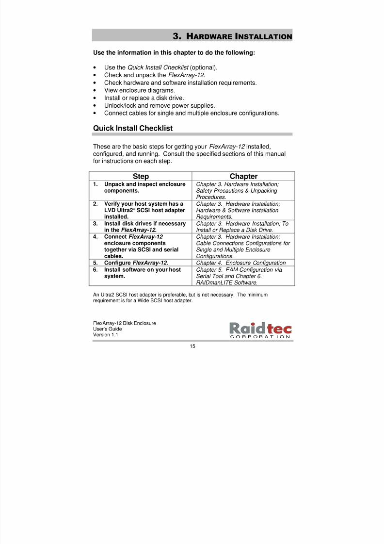
Quick Install Checklist
These are the basic steps for getting your FlexArray-12 installed,configured, and running. Consult the specified sections of this manualfor instructions on each step.
Step Chapter1. Unpack and inspect enclosure
components.
Chapter 3. Hardware Installation;
Safety Precautions & Unpacking Procedures.
2. Verify your host system has aLVD Ultra2* SCSI host adapterinstalled.
Chapter 3. Hardware Installation; Hardware & Software Installation Requirements.
3. Install disk drives if necessaryin the FlexArray-12 .
Chapter 3. Hardware Installation; To Install or Replace a Disk Drive.
4. Connect FlexArray-12 enclosure componentstogether via SCSI and serialcables.
Chapter 3. Hardware Installation; Cable Connections Configurations for Single and Multiple Enclosure Configurations.
5. Configure FlexArray-12 . Chapter 4. Enclosure Configuration
6. Install software on your hostsystem.
Chapter 5. EAM Configuration via Serial Tool and Chapter 6.RAIDmanLITE Software.
An Ultra2 SCSI host adapter is preferable, but is not necessary. The minimumrequirement is for a Wide SCSI host adapter.
8/3/2019 Flex Array 12 Version 1.1
http://slidepdf.com/reader/full/flex-array-12-version-11 22/102
FlexArray-12 Disk EnclosureUser’s GuideVersion 1.1
16
Safety Precautions & Unpacking Procedures
Place your FlexArray-12 disk enclosure component box(es) near thelocation(s) where they will be permanently installed. During theunpacking and installation process, please observe the followingprecautions.
• Open all boxes carefully to prevent any damage to the contents.
• Observe proper electrostatic protective measures, including useof a ground strap, when handling Electro Static Discharge (ESD)sensitive devices such as, disk drives.
• Check components and accessories shipped against packinglists. If the contents do not match the packing lists, contact yourSupplier or Raidtec sales representative immediately for assistance.
• Perform a visual check on your FlexArray-12 enclosure(s) and allaccessories and optional equipment for any physical damage thatmay have occurred during shipment.
NOTE: Interstate commerce rules require immediate reporting of goods
damaged in shipment (usually within 24 hours) in order to receive compensation for damage or losses from the shipper.
• Save all boxes and packing materials received in the originalshipment of your FlexArray-12 components and accessories in caseyou need to further transport or ship your FlexArray-12 .
NOTE: To maintain adequate air flow and maximum cooling in the FlexArray-12 enclosure(s), it is important to remove all packing material.
• Complete and return your warranty registration card.
• Retain your invoice. All warranty repairs require proof ofpurchase. Further, the product must be returned in the originalpackaging.
8/3/2019 Flex Array 12 Version 1.1
http://slidepdf.com/reader/full/flex-array-12-version-11 23/102
FlexArray-12 Disk EnclosureUser’s GuideVersion 1.1
17
C O R P O R A T I O N
Hardware & Software Installation Requirements
To successfully install your FlexArray-12 , you will need thefollowing hardware and software:
• One (1) FlexArray-12 with disk drives installed.
• One (1) third-party SCSI host adapter installed in the host system.(You will need a dual channel SCSI host adapter if you are using a
two channel FlexArray-12 enclosure.)
• One (1) SCSI cable for use between the FlexArray-12 and the SCSIhost adapter. (You will need a second SCSI cable to connect to theSCSI host adapter if you are using a two channel FlexArray-12 enclosure.)
To use the RAIDmanLITE GUI for configuration, management andmonitoring, you will require the following:
• One (1) PC running Windows 95, 98 or Windows NT to function asa host system for the RAIDmanLITE software. (You can use thehost system connected to the FlexArray-12 to run the
RAIDmanLITE software if the host system is running Windows 95,98 or Windows NT.)
Additional Installation Requirements
A basic understanding of the following topics will assure a successfulFlexArray-12 installation:
• SCSI hard disk technology.
• RAID concepts.
8/3/2019 Flex Array 12 Version 1.1
http://slidepdf.com/reader/full/flex-array-12-version-11 24/102
FlexArray-12 Disk EnclosureUser’s GuideVersion 1.1
18
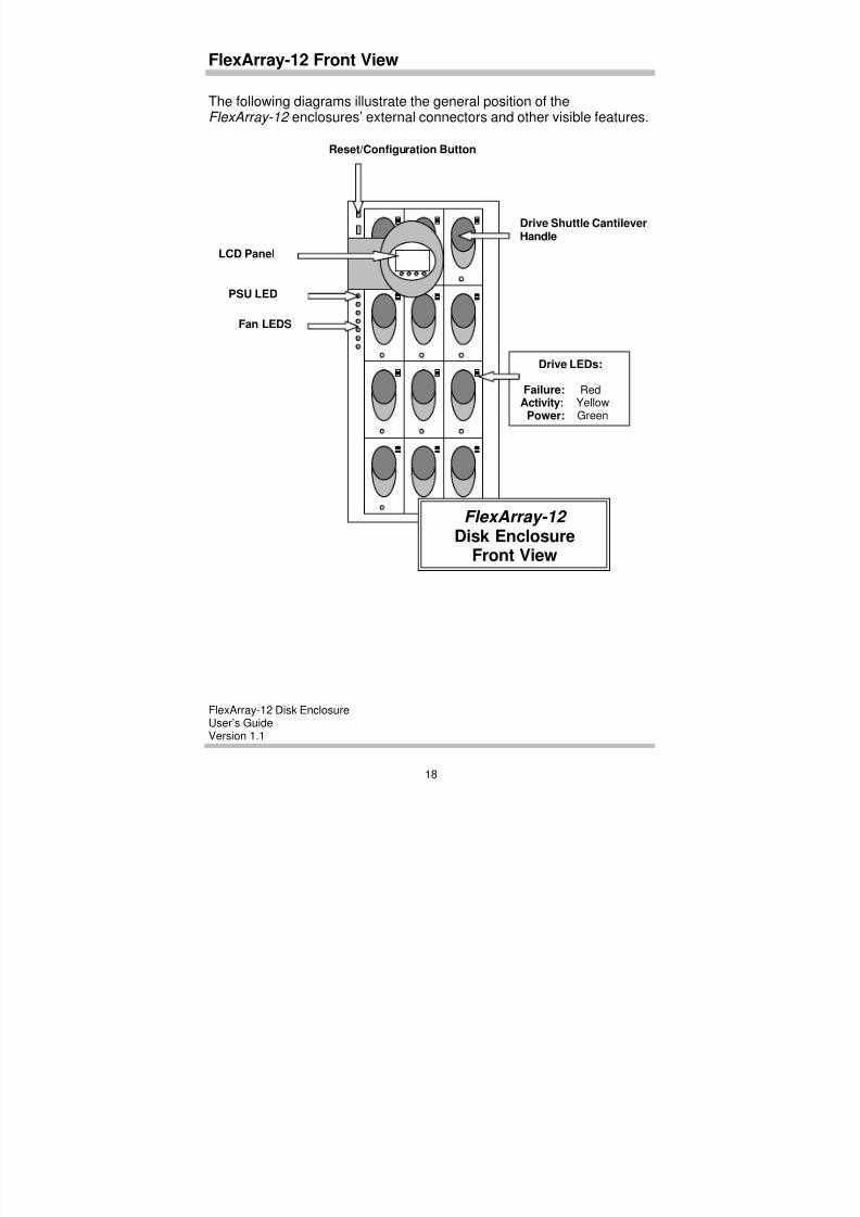
FlexArray-12 Front View
The following diagrams illustrate the general position of theFlexArray-12 enclosures’ external connectors and other visible features.
LCD Panel
Drive Shuttle CantileverHandle
Fan LEDS
PSU LED
Drive LEDs:
Failure: RedActivity: Yellow
Power: Green
Reset/Configuration Button
FlexArray-12 Disk Enclosure
Front View
8/3/2019 Flex Array 12 Version 1.1
http://slidepdf.com/reader/full/flex-array-12-version-11 25/102
FlexArray-12 Disk EnclosureUser’s GuideVersion 1.1
19
C O R P O R A T I O N
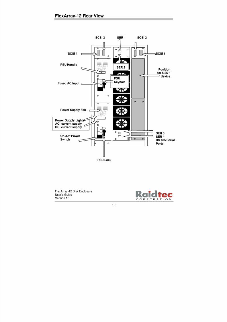
FlexArray-12 Rear View
SCSI 2
PSUKeyhole
SCSI 3
SCSI 1
PSU Lock
SER 3SER 4RS 485 SerialPorts
Fused AC Input
On /Off PowerSwitch
PSU Handle
Power Supply LightsAC: current supplyDC: current supply
Power Supply Fan
Positionfor 5.25 “
device
SER 1
SCSI 4
SER 2
8/3/2019 Flex Array 12 Version 1.1
http://slidepdf.com/reader/full/flex-array-12-version-11 26/102
FlexArray-12 Disk EnclosureUser’s GuideVersion 1.1
20
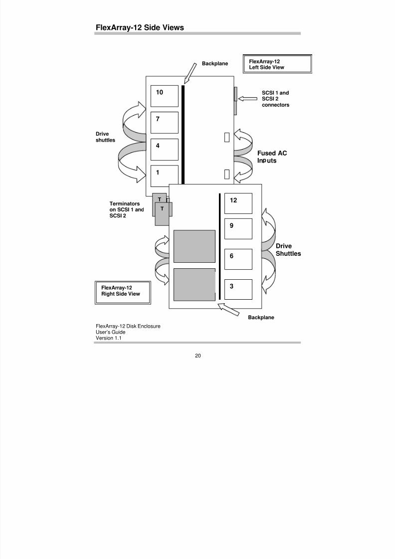
FlexArray-12 Side Views
Terminatorson SCSI 1 andSCSI 2
DriveShuttles
Backplane
Backplane
10
7
1
4
Driveshuttles
Fused ACIn uts
FlexArray-12Left Side View
FlexArray-12
Right Side View
12
9
6
3
SCSI 1 and
SCSI 2connectors
T
T
8/3/2019 Flex Array 12 Version 1.1
http://slidepdf.com/reader/full/flex-array-12-version-11 27/102
FlexArray-12 Disk EnclosureUser’s GuideVersion 1.1
21
C O R P O R A T I O N
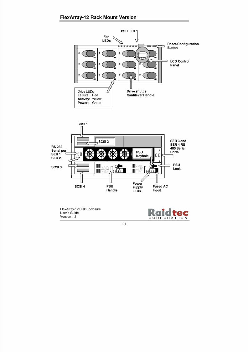
FlexArray-12 Rack Mount Version
PSUKeyhole
FanLEDs
PSU LED
Reset/ConfigurationButton
Drive LEDsFailure: RedActivity: YellowPower: Green
Drive shuttleCantilever Handle
LCD ControlPanel
PSULock
SER 3 andSER 4 RS485 SerialPorts
SCSI 2
SCSI 1
SCSI 4 Fused ACInput
PSUHandle
PowersupplyLEDs
SCSI 3
RS 232Serial portSER 1SER 2
8/3/2019 Flex Array 12 Version 1.1
http://slidepdf.com/reader/full/flex-array-12-version-11 28/102
FlexArray-12 Disk EnclosureUser’s GuideVersion 1.1
22
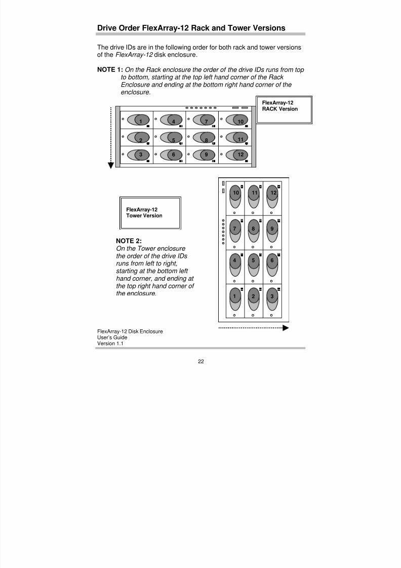
Drive Order FlexArray-12 Rack and Tower Versions
The drive IDs are in the following order for both rack and tower versionsof the FlexArray-12 disk enclosure.
NOTE 1: On the Rack enclosure the order of the drive IDs runs from top to bottom, starting at the top left hand corner of the Rack Enclosure and ending at the bottom right hand corner of the enclosure.
FlexArray-12RACK Version
1 4 7 10
2 5 8 11
3 6 9 12
NOTE 2: On the Tower enclosure the order of the drive IDs runs from left to right,starting at the bottom left hand corner, and ending at the top right hand corner of the enclosure.
FlexArray-12Tower Version
1
4
7
10 11 12
8 9
5 6
2 3
8/3/2019 Flex Array 12 Version 1.1
http://slidepdf.com/reader/full/flex-array-12-version-11 29/102
FlexArray-12 Disk EnclosureUser’s GuideVersion 1.1
23
C O R P O R A T I O N
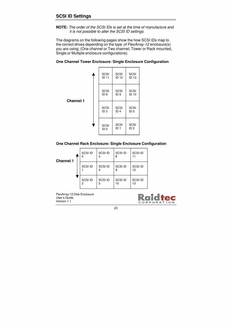
SCSI ID Settings
NOTE: The order of the SCSI IDs is set at the time of manufacture and it is not possible to alter the SCSI ID settings.
The diagrams on the following pages show the how SCSI IDs map tothe correct drives depending on the type of FlexArray-12 enclosure(s)you are using; (One channel or Two channel, Tower or Rack mounted,Single or Multiple enclosure configurations).
One Channel Tower Enclosure: Single Enclosure Configuration
One Channel Rack Enclosure: Single Enclosure Configuration
Channel 1
Channel 1
SCSIID 11
SCSIID 12
SCSIID 13
SCSIID 8
SCSIID 0
SCSIID 3
SCSIID 9
SCSIID 10
SCSIID 4
SCSIID 5
SCSIID 1
SCSIID 2
SCSI ID11
SCSI ID12
SCSI ID13
SCSI ID8
SCSI ID0
SCSI ID3
SCSI ID9
SCSI ID10
SCSI ID4
SCSI ID5
SCSI ID1
SCSI ID2
8/3/2019 Flex Array 12 Version 1.1
http://slidepdf.com/reader/full/flex-array-12-version-11 30/102
FlexArray-12 Disk EnclosureUser’s GuideVersion 1.1
24
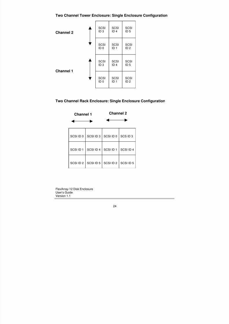
Two Channel Tower Enclosure: Single Enclosure Configuration
Channel 2
Channel 1
Two Channel Rack Enclosure: Single Enclosure Configuration
SCSIID 3
SCSIID 4
SCSIID 5
SCSIID 0
SCSIID 0
SCSIID 3
SCSIID 1
SCSIID 2
SCSIID 4
SCSIID 5
SCSIID 1
SCSIID 2
Channel 1 Channel 2
SCS ID 3
SCSI ID 4
SCSI ID 5
SCSI ID 0
SCSI ID 0 SCSI ID 3
SCSI ID 1
SCSI ID 2
SCSI ID 4
SCSI ID 5
SCSI ID 1
SCSI ID 2
8/3/2019 Flex Array 12 Version 1.1
http://slidepdf.com/reader/full/flex-array-12-version-11 31/102
FlexArray-12 Disk EnclosureUser’s GuideVersion 1.1
25
C O R P O R A T I O N
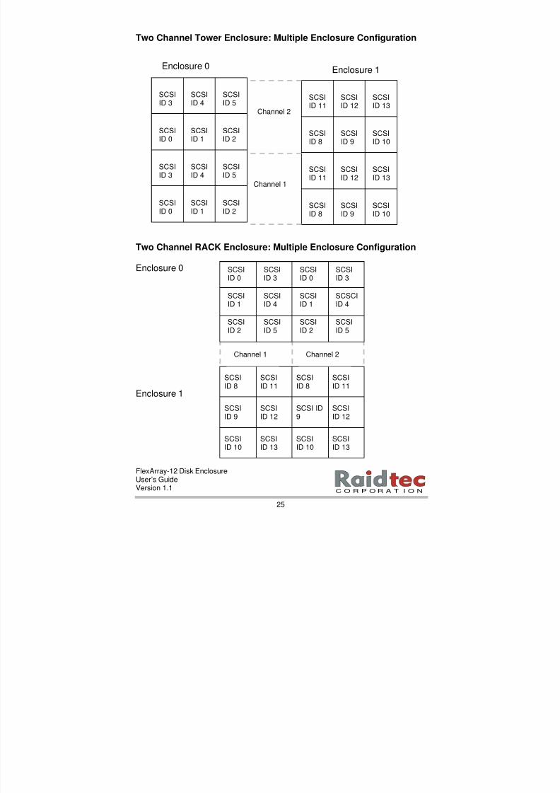
Two Channel Tower Enclosure: Multiple Enclosure Configuration
Two Channel RACK Enclosure: Multiple Enclosure Configuration
Enclosure 0
Enclosure 1
Channel 1
Enclosure 0 Enclosure 1
Channel 2
SCSIID 11
SCSIID 12
SCSIID 13
SCSIID 8
SCSIID 8
SCSIID 11
SCSIID 9
SCSIID 10
SCSIID 12
SCSIID 13
SCSIID 9
SCSIID 10
SCSIID 3
SCSIID 4
SCSIID 5
SCSI
ID 0
SCSIID 0
SCSIID 3
SCSI
ID 1
SCSI
ID 2
SCSIID 4
SCSIID 5
SCSIID 1
SCSIID 2
SCSIID 11
SCSI
ID 12
SCSIID 13
SCSIID 8
SCSIID 8
SCSIID 11
SCSI ID
9
SCSIID 10
SCSI
ID 12
SCSIID 13
SCSI
ID 9
SCSIID 10
SCSIID 5
SCSIID 2
SCSIID 2
SCSIID 5
SCSI
ID 3
SCSI
ID 0
SCSI
ID 0
SCSI
ID 3
SCSCIID 4
SCSIID 1
SCSIID 1
SCSIID 4
Channel 1 Channel 2
8/3/2019 Flex Array 12 Version 1.1
http://slidepdf.com/reader/full/flex-array-12-version-11 32/102
FlexArray-12 Disk EnclosureUser’s GuideVersion 1.1
26
To Install or Replace a Disk Drive
The FlexArray-12 disk drive shuttles are designed to take SCA 3.5” diskdrives. The removable shuttles provide mounting holes to securelyinstall disk drives. Once installed in the shuttle, the disk drive’s 40 pin,SCA connector, mates correctly with the backplane. (Raidtec-suppliedSCA drives come pre-configured in shuttles ready for insertion into theFlexArray-12 enclosure.)
Use the following instructions to:
• Install a third-party drive.
• Replace a third-party drive.
1. Insert the key in the lock, and turn the key to the right.
2. While holding the key in this position, pull the shuttle handleforward. This action disconnects the drive’s SCA interface andremoves power from the disk drive.
3. Release the key. If a drive is already installed in the shuttle, allowthe drive to spin down completely before fully extracting the shuttle
from the bay assembly.
NOTE: Please observe proper Electro Static Discharge (ESD)protective measures when handling disk drives.
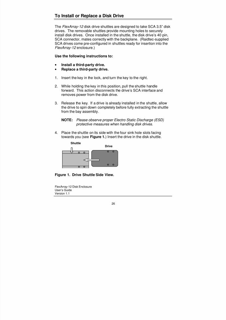
4. Place the shuttle on its side with the four sink hole slots facingtowards you (see Figure 1.) Insert the drive in the disk shuttle.
Figure 1. Drive Shuttle Side View.
DriveShuttle
8/3/2019 Flex Array 12 Version 1.1
http://slidepdf.com/reader/full/flex-array-12-version-11 33/102
FlexArray-12 Disk EnclosureUser’s GuideVersion 1.1
27
C O R P O R A T I O N
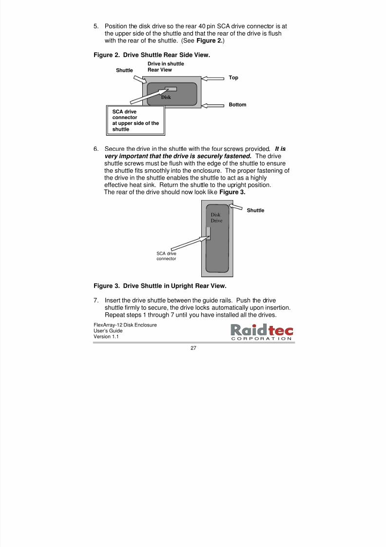
5. Position the disk drive so the rear 40 pin SCA drive connector is atthe upper side of the shuttle and that the rear of the drive is flushwith the rear of the shuttle. (See Figure 2.)
Figure 2. Drive Shuttle Rear Side View.
6. Secure the drive in the shuttle with the four screws provided. It is very important that the drive is securely fastened. The driveshuttle screws must be flush with the edge of the shuttle to ensurethe shuttle fits smoothly into the enclosure. The proper fastening ofthe drive in the shuttle enables the shuttle to act as a highlyeffective heat sink. Return the shuttle to the upright position.
The rear of the drive should now look like Figure 3.
Figure 3. Drive Shuttle in Upright Rear View.
7. Insert the drive shuttle between the guide rails. Push the driveshuttle firmly to secure, the drive locks automatically upon insertion.Repeat steps 1 through 7 until you have installed all the drives.
Disk
Drive
SCA driveconnector
Shuttle
Drive in shuttleRear ViewShuttle
Disk
SCA driveconnectorat upper side of theshuttle
Bottom
Top

8/3/2019 Flex Array 12 Version 1.1
http://slidepdf.com/reader/full/flex-array-12-version-11 34/102
FlexArray-12 Disk EnclosureUser’s GuideVersion 1.1
28
Power Supply Unit Lock
On each Power Supply Unit (PSU) on your FlexArray-12 enclosurethere is a Power Supply Unit (PSU) Lock to secure the PSU into placeon the FlexArray-12 .
To Unlock a Power Supply Unit
1. Press the power supply switch on the rear of the power supply unitto the OFF position.
Power supply unit switched off.
PSU LOCK in locked position.
Power Supply Unit in locked position.
PSU Keyhole
PSU Keyhole
Power supply On/Off switch
PSU Lock in locked position.
8/3/2019 Flex Array 12 Version 1.1
http://slidepdf.com/reader/full/flex-array-12-version-11 35/102
FlexArray-12 Disk EnclosureUser’s GuideVersion 1.1
29
C O R P O R A T I O N
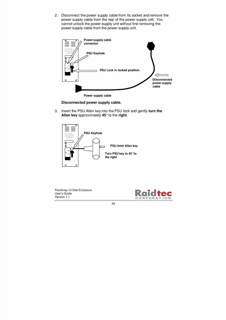
2. Disconnect the power supply cable from its socket and remove thepower supply cable from the rear of the power supply unit. Youcannot unlock the power supply unit without first removing thepower supply cable from the power supply unit.
Disconnected power supply cable.
3. Insert the PSU Allen key into the PSU lock and gently turn theAllen key approximately 45°to the right.
Disconnectedpower supplycable
Power supply cable
Power supply cableconnector
PSU Keyhole
PSU Lock in locked position.
PSU 4mm Allen key
Turn PSU key to 45°tothe right
PSU Keyhole
8/3/2019 Flex Array 12 Version 1.1
http://slidepdf.com/reader/full/flex-array-12-version-11 36/102
FlexArray-12 Disk EnclosureUser’s GuideVersion 1.1
30
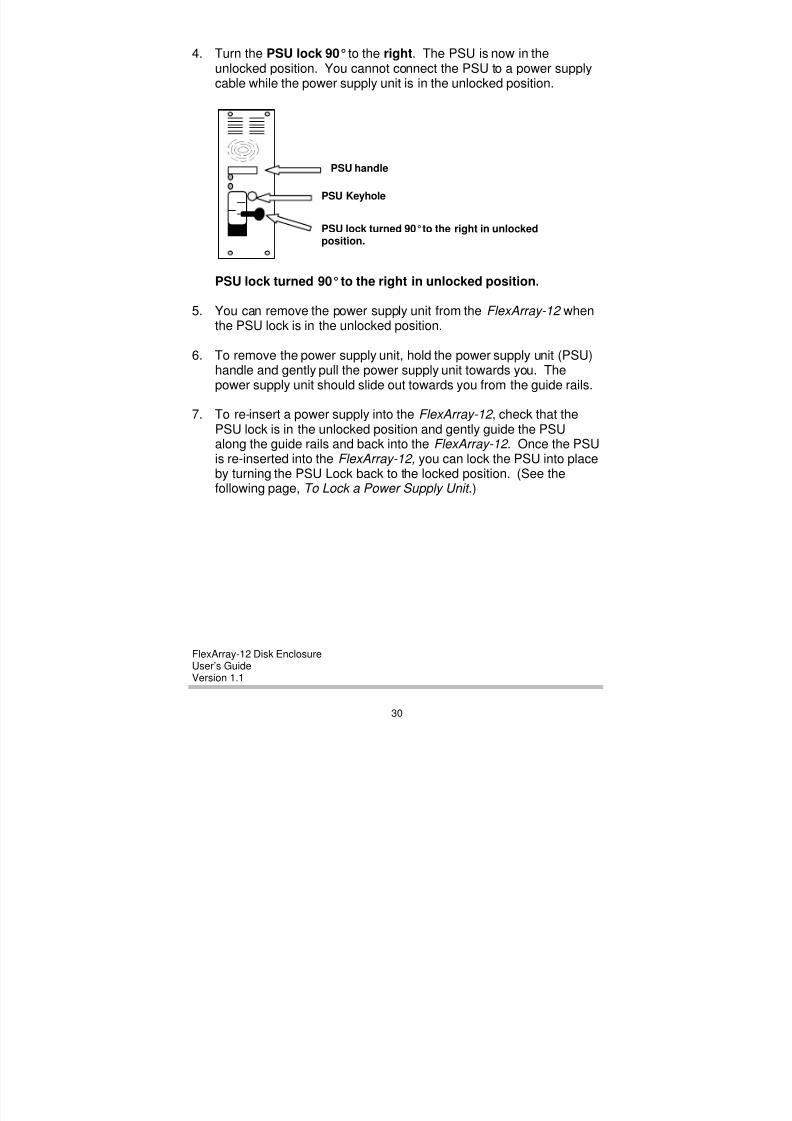
4. Turn the PSU lock 90°to the right. The PSU is now in theunlocked position. You cannot connect the PSU to a power supplycable while the power supply unit is in the unlocked position.
PSU lock turned 90° to the right in unlocked position.
5. You can remove the power supply unit from the FlexArray-12 whenthe PSU lock is in the unlocked position.
6. To remove the power supply unit, hold the power supply unit (PSU)handle and gently pull the power supply unit towards you. Thepower supply unit should slide out towards you from the guide rails.
7. To re-insert a power supply into the FlexArray-12 , check that thePSU lock is in the unlocked position and gently guide the PSUalong the guide rails and back into the FlexArray-12 . Once the PSUis re-inserted into the FlexArray-12, you can lock the PSU into placeby turning the PSU Lock back to the locked position. (See thefollowing page, To Lock a Power Supply Unit .)
PSU handle
PSU Keyhole
PSU lock turned 90°to the right in unlockedposition.
8/3/2019 Flex Array 12 Version 1.1
http://slidepdf.com/reader/full/flex-array-12-version-11 37/102
FlexArray-12 Disk EnclosureUser’s GuideVersion 1.1
31
C O R P O R A T I O N
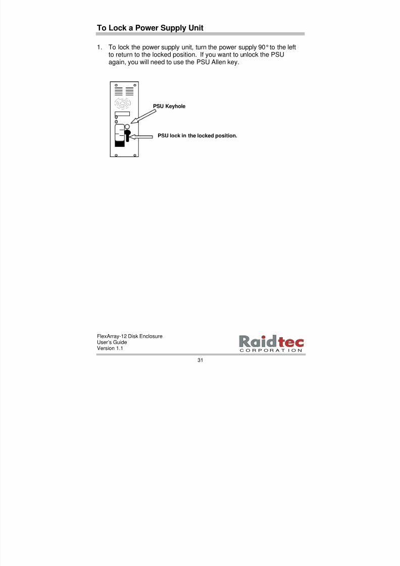
To Lock a Power Supply Unit
1. To lock the power supply unit, turn the power supply 90° to the leftto return to the locked position. If you want to unlock the PSUagain, you will need to use the PSU Allen key.
PSU Keyhole
PSU lock in the locked position.

8/3/2019 Flex Array 12 Version 1.1
http://slidepdf.com/reader/full/flex-array-12-version-11 38/102
FlexArray-12 Disk EnclosureUser’s GuideVersion 1.1
32
Cable Connections for One Channel Single EnclosureConfiguration
1. Connect an RS-232 Serial Cable from the SER 2 serial port on therear of the FlexArray-12 (enclosure 0) to a serial port on your hostsystem. This cable runs RAIDmanLITE (and/or the EAMConfiguration using Serial Tool utility software).
2. Connect an LVD SCSI Cable from the SCSI 2 connector at the rear
of the FlexArray-12 (enclosure 0) to the SCSI Adapter Connector on your host system.
3. Connect the ends of the power supply cables to the fused ACInput connectors at the rear of the FlexArray-12 enclosure.
4. Connect an external terminator to the SCSI 4 connector at therear of the enclosure. Check the terminator is in place beforepowering up the enclosure.
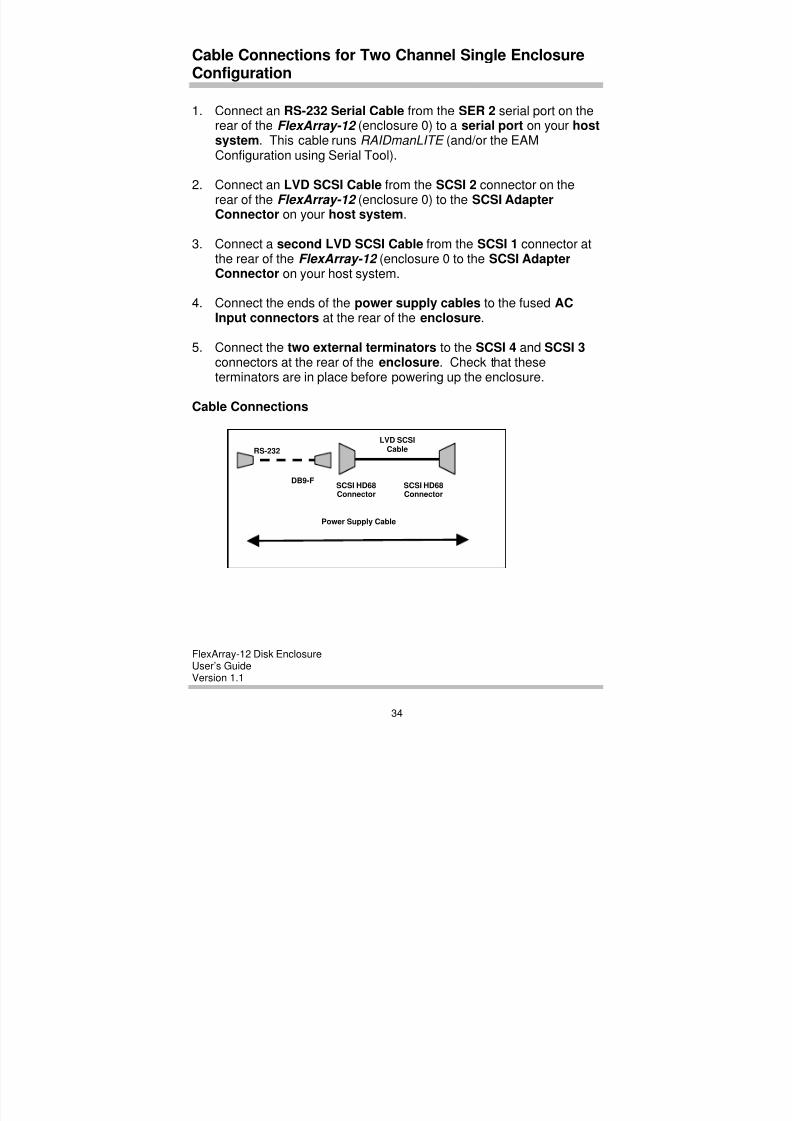
Cable Connections
SCSI HD68Connector
SCSI HD68Connector
LVD SCSICable
DB9-F
RS-232
Power Supply Cable
8/3/2019 Flex Array 12 Version 1.1
http://slidepdf.com/reader/full/flex-array-12-version-11 39/102
FlexArray-12 Disk EnclosureUser’s GuideVersion 1.1
33
C O R P O R A T I O N
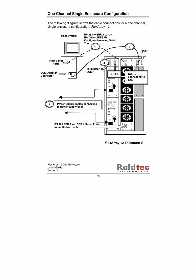
Terminator onSCSI 4
One Channel Single Enclosure Configuration
The following diagram shows the cable connections for a one channel,single enclosure configuration, FlexArray-12 .
RS 232 to SER 2 to runRAIDmanLITE/EAMConfiguration using SerialTool
SCSI AdapterConnector
Host SerialPorts
Host System
FlexArray-12 Enclosure 0
Power Supply cables connectingto power supply units
RS 485 SER 3 and SER 4 Serial Portsfor multi-drop cable.
3
1
SCSI 2connecting tohost
4
2
SCSI 1
SCSI 3
8/3/2019 Flex Array 12 Version 1.1
http://slidepdf.com/reader/full/flex-array-12-version-11 40/102
FlexArray-12 Disk EnclosureUser’s GuideVersion 1.1
34
Cable Connections for Two Channel Single EnclosureConfiguration
1. Connect an RS-232 Serial Cable from the SER 2 serial port on therear of the FlexArray-12 (enclosure 0) to a serial port on your hostsystem. This cable runs RAIDmanLITE (and/or the EAMConfiguration using Serial Tool).
2. Connect an LVD SCSI Cable from the SCSI 2 connector on the
rear of the FlexArray-12 (enclosure 0) to the SCSI AdapterConnector on your host system.
3. Connect a second LVD SCSI Cable from the SCSI 1 connector atthe rear of the FlexArray-12 (enclosure 0 to the SCSI AdapterConnector on your host system.
4. Connect the ends of the power supply cables to the fused ACInput connectors at the rear of the enclosure.
5. Connect the two external terminators to the SCSI 4 and SCSI 3 connectors at the rear of the enclosure. Check that theseterminators are in place before powering up the enclosure.
Cable Connections
SCSI HD68Connector
SCSI HD68Connector
LVD SCSICable
DB9-F
RS-232
Power Supply Cable
8/3/2019 Flex Array 12 Version 1.1
http://slidepdf.com/reader/full/flex-array-12-version-11 41/102
FlexArray-12 Disk EnclosureUser’s GuideVersion 1.1
35
C O R P O R A T I O N
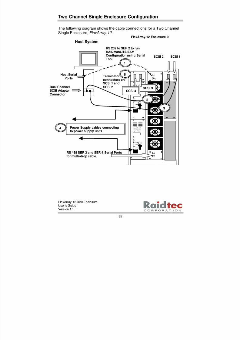
Terminatorconnectors onSCSI 1 andSCSI 2
Two Channel Single Enclosure Configuration
The following diagram shows the cable connections for a Two ChannelSingle Enclosure, FlexArray-12 .
RS 232 to SER 2 to runRAIDmanLITE/EAMConfiguration using Serial
Tool
Dual ChannelSCSI AdapterConnector
Host SerialPorts
Host System
FlexArray-12 Enclosure 0
Power Supply cables connectingto power supply units
2
RS 485 SER 3 and SER 4 Serial Portsfor multi-drop cable.
4
5
SCSI 3SCSI 4
3
1
SCSI 2 SCSI 1
8/3/2019 Flex Array 12 Version 1.1
http://slidepdf.com/reader/full/flex-array-12-version-11 42/102
FlexArray-12 Disk EnclosureUser’s GuideVersion 1.1
36
Cable Connections for Two Channel Multiple EnclosureConfiguration
1. Connect an RS 232 cable from SER 2 on the rear of theFlexArray-12 (enclosure 0) to a serial port on your host system.This cable runs RAIDmanLITE (and/or EAM Configuration usingSerial Tool utility software).
2. Connect an LVD SCSI Cable from the SCSI 2 connector on the
rear of the FlexArray-12 enclosure to the SCSI Adapterconnector on your host system.
3. Connect a second LVD SCSI Cable from the SCSI 1 connector onthe rear of the FlexArray-12 enclosure to the SCSI Adapterconnector on your host system.
4. Connect an LVD SCSI cable from the SCSI 4 connector on yourFlexArray-12 (enclosure 0) on to the SCSI 2 connector on yourFlexArray-12 expansion enclosure (enclosure 1).
5. Connect a second LVD SCSI cable from the SCSI 3 connector onthe FlexArray-12 (enclosure 0) to the SCSI 1 connector on your
FlexArray-12 expansion enclosure (enclosure 1).
6. Connect an RS 485 multi-drop cable from SER 4 on theFlexArray-12 (enclosure 0) to SER 2 on your expansion enclosureFlexArray-12 (enclosure 1).
7. Connect the two external terminators to the SCSI 4 and SCSI 3connectors at the rear of the FlexArray-12 (enclosure 1). Place aserial port terminator on SER 4 on the last enclosure in theconfiguration. Check that all terminators are in place beforepowering up the enclosure.
8. Connect the ends of the power supply cables to the fused ACInput connectors at the rear of the FlexArray-12 enclosures. Plugin the power supply cables.

8/3/2019 Flex Array 12 Version 1.1
http://slidepdf.com/reader/full/flex-array-12-version-11 43/102
FlexArray-12 Disk EnclosureUser’s GuideVersion 1.1
37
C O R P O R A T I O N
Two Channel Multiple Enclosure Configuration
The following diagram shows the cable connections for Two ChannelMultiple Enclosures.
SCSI 1
SCSI 4
Terminator on SER 4on the last enclosurein the configuration.
SER 2
SCSI adapterconnector
Host Serial Port
Host System
SCSI 4
RS 485 Multi drop cableconnection SER 4 onFlexArray-12 (enclosure 0)to SER 3 FlexArray-12(enclosure 1).
FlexArray-12Enclosure 0
6
7
Power supplycablesconnecting topower supply
8
SCSI 3
4
5
Terminator
connectors onSCSI 3 and SCSI 4
1
SCSI 3
SCSI 22
7
SCSI 1
3
FlexArray-12Enclosure 1
SCSI 2

8/3/2019 Flex Array 12 Version 1.1
http://slidepdf.com/reader/full/flex-array-12-version-11 44/102
FlexArray-12 Disk EnclosureUser’s GuideVersion 1.1
38
4. ENCLOSURE CONFIGURATION
This chapter describes how to configure your FlexArray-12 usingthe LCD Control Panel on the front of the enclosure.
NOTE: If your enclosures do not have LCD panels you can configure your enclosure IDs via EAM Configuration using Serial Tool.You can also use this option to enable temperature probes and
to set temperature thresholds. For more information on this option, refer to Chapter 5. EAM Configuration using Serial Tool.
Use the following instructions to:
• Configure the FlexArray-12 (enclosure 0) ID.
• Enable Temperature setting.
• Change Buzzer Settings (optional).
• Configure the expansion enclosure’s ID and Enable Temperaturesetting.
Once you use either the LCD panel or EAM Configuration via Serial
Tool, to configure enclosure IDs, enable temperature sensors and settemperature thresholds, you can then use the RAIDmanLITE softwareto monitor any changes in the enclosures in your configuration.
NOTE: 1 The LCD control panel is a factory fitted option with the FlexArray-12 enclosure. In instances where your enclosures do not have LCD Panels you will need to configure enclosure IDs via EAM Configuration using Serial Tool (see Chapter 5 of this manual), before you can use the RAIDmanLITE software to monitor your enclosure configuration.

8/3/2019 Flex Array 12 Version 1.1
http://slidepdf.com/reader/full/flex-array-12-version-11 45/102
FlexArray-12 Disk EnclosureUser’s GuideVersion 1.1
39
C O R P O R A T I O N
Quick Configuration Checklist
The following checklist outlines the basic steps involved in getting yourFlexArray-12 enclosure(s) up and running. Consult the specificconfiguration sections of this manual for instructions on how to performeach step.
ü Verify all enclosure hardware and software components areinstalled on your host system connected to the FlexArray-12 disk
enclosure.
ü Verify that all external terminators are attached to the SCSI 1 (andSCSI 2 if you have a two channel subsystem) in both single andmultiple enclosure configurations. In a multiple enclosureconfiguration, check that there is an RS 485 serial terminator onSER 4 on the last enclosure in the configuration.
ü Configure all the FlexArray-12 enclosure IDs via the LCD controlpanel on the front of each enclosure.
NOTE 1: The Master Unit FlexArray-12 enclosure is set at Enclosure ID 0 to enable serial port communication with the
host system to use the RAIDmanLITE software.
NOTE:2 The Master Enclosure Unit in a multiple enclosure configuration does not control the expansion enclosures’ settings via the LCD Panel. You will need to configure each individual enclosure’s ID via each enclosure’s LCD panel. If the enclosures do not have LCD panels you will need to configure each enclosure ID via the EAM Configuration using Serial Tool. (See Chapter 5. of this manual for more information).
ü Configure Enclosures Temperature settings via the LCD controlpanel or via RAIDmanLITE (optional).
8/3/2019 Flex Array 12 Version 1.1
http://slidepdf.com/reader/full/flex-array-12-version-11 46/102
FlexArray-12 Disk EnclosureUser’s GuideVersion 1.1
40
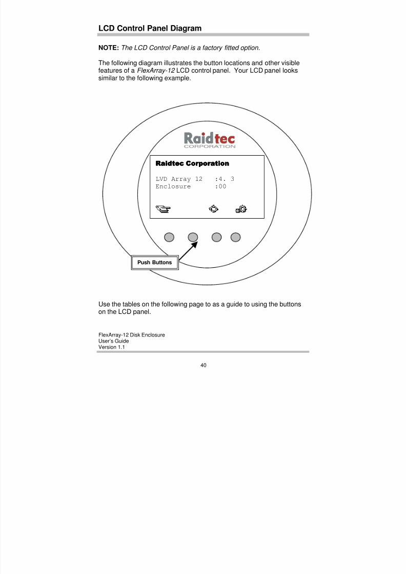
LCD Control Panel Diagram
NOTE: The LCD Control Panel is a factory fitted option.
The following diagram illustrates the button locations and other visiblefeatures of a FlexArray-12 LCD control panel. Your LCD panel lookssimilar to the following example.
Use the tables on the following page to as a guide to using the buttonson the LCD panel.
Raidtec CorporationRaidtec CorporationRaidtec CorporationRaidtec Corporation
LVD Array 12 :4. 3
Enclosure :00
Push Buttons

8/3/2019 Flex Array 12 Version 1.1
http://slidepdf.com/reader/full/flex-array-12-version-11 47/102
FlexArray-12 Disk EnclosureUser’s GuideVersion 1.1
41
C O R P O R A T I O N
LCD Panel Tables
Refer to these tables as a guide to the uses and functions of theFlexArray-12 LCD Panel. The LCD panel has two sets of menu iconsthat represent the functions of the LCD buttons under the display.
• Main Menu Icons. Provide access to the various menus.
• Sub Menu Icons. Allow users to select options.
Main Menu Icon Table
The Main menu icons and their functions are as follows:
Button Label MainMenuIcon
Function
ALARM RESET(ERROR LOG)
Displays only when the Error Log Alarm sounds.Press to halt the alarm and enter the Error StatusMenu.
Displays the Error Log.
RECREATE DRIVE(View/Rebuild RAIDset) Not available in JBODS.
SELECTThis icon rotates when you perform an action on theRAIDmanLITE software and each timeRAIDmanLITE sends a command to the EAM (everyfour or five 5 seconds). The button clears the LCDdisplay.
ENTER(CONFIGURATION) Displays Configuration Menu.
Sub Menu Icon Table
The sub menu icons allow users to select and enter the options theywant to use in the LCD panel sub menu.
Button Sub MenuIcon
Function
UP Scrolls up utility menu choices.
DOWN Scrolls down utility menu choices.
ENTER ENTER button, accepts choices.
8/3/2019 Flex Array 12 Version 1.1
http://slidepdf.com/reader/full/flex-array-12-version-11 48/102
FlexArray-12 Disk EnclosureUser’s GuideVersion 1.1
42
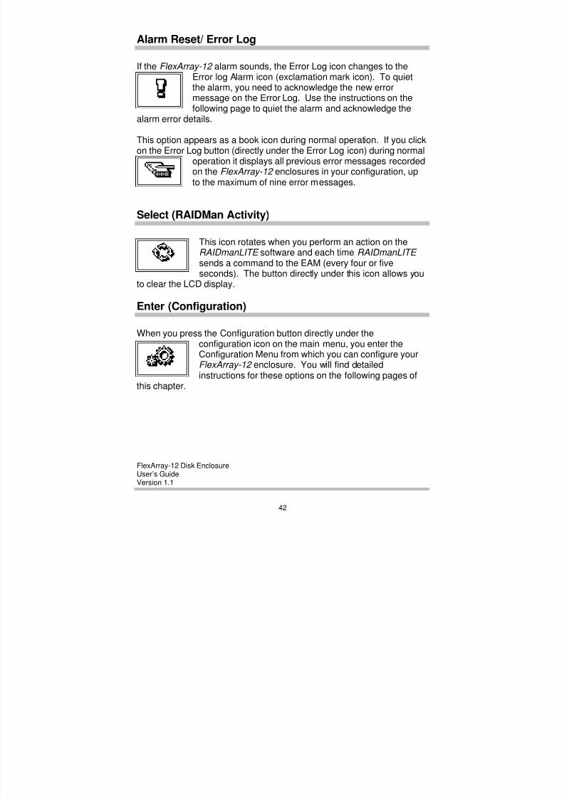
Alarm Reset/ Error Log
If the FlexArray-12 alarm sounds, the Error Log icon changes to theError log Alarm icon (exclamation mark icon). To quietthe alarm, you need to acknowledge the new errormessage on the Error Log. Use the instructions on thefollowing page to quiet the alarm and acknowledge the
alarm error details.
This option appears as a book icon during normal operation. If you clickon the Error Log button (directly under the Error Log icon) during normal
operation it displays all previous error messages recordedon the FlexArray-12 enclosures in your configuration, upto the maximum of nine error messages.
Select (RAIDMan Activity)
This icon rotates when you perform an action on theRAIDmanLITE software and each time RAIDmanLITE sends a command to the EAM (every four or fiveseconds). The button directly under this icon allows you
to clear the LCD display.
Enter (Configuration)
When you press the Configuration button directly under theconfiguration icon on the main menu, you enter theConfiguration Menu from which you can configure yourFlexArray-12 enclosure. You will find detailedinstructions for these options on the following pages of
this chapter.
8/3/2019 Flex Array 12 Version 1.1
http://slidepdf.com/reader/full/flex-array-12-version-11 49/102
FlexArray-12 Disk EnclosureUser’s GuideVersion 1.1
43
C O R P O R A T I O N
To Quiet the Error Log Alarm
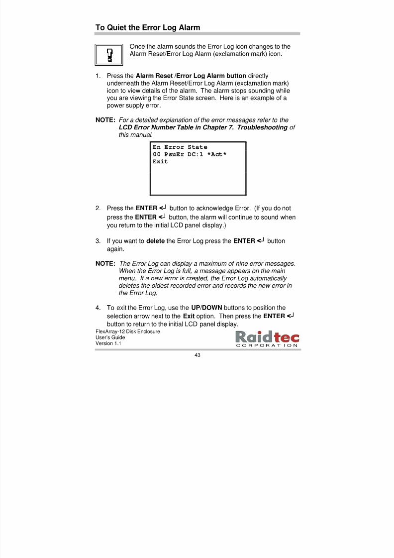
Once the alarm sounds the Error Log icon changes to theAlarm Reset/Error Log Alarm (exclamation mark) icon.
1. Press the Alarm Reset /Error Log Alarm button directlyunderneath the Alarm Reset/Error Log Alarm (exclamation mark)icon to view details of the alarm. The alarm stops sounding while
you are viewing the Error State screen. Here is an example of apower supply error.
NOTE: For a detailed explanation of the error messages refer to the LCD Error Number Table in Chapter 7. Troubleshooting of this manual .
2. Press the ENTER < ┘ button to acknowledge Error. (If you do not
press the ENTER < ┘ button, the alarm will continue to sound when
you return to the initial LCD panel display.)
3. If you want to delete the Error Log press the ENTER < ┘ button
again.
NOTE: The Error Log can display a maximum of nine error messages.When the Error Log is full, a message appears on the main menu. If a new error is created, the Error Log automatically deletes the oldest recorded error and records the new error in
the Error Log.
4. To exit the Error Log, use the UP/DOWN buttons to position the
selection arrow next to the Exit option. Then press the ENTER < ┘
button to return to the initial LCD panel display.
En Error State
00 PsuEr DC:1 *Act*Exit
8/3/2019 Flex Array 12 Version 1.1
http://slidepdf.com/reader/full/flex-array-12-version-11 50/102
FlexArray-12 Disk EnclosureUser’s GuideVersion 1.1
44
To Initiate the LCD Configuration Menu
You can access the Configuration Menu from the LCD control panel onthe front of a FlexArray-12 Disk Enclosure. The FlexArray-12 enclosureconnected to the host system is known as the Master Unit. All otherenclosures are expansion enclosures. Remember to set the Masterenclosure’s ID at 0.
The enclosure configuration menu contains options that allow youto:
• Set an enclosure’s ID.
• Configure ambient temperature sensor with appropriatethresholds (optional).
• Change Buzzer settings (optional).
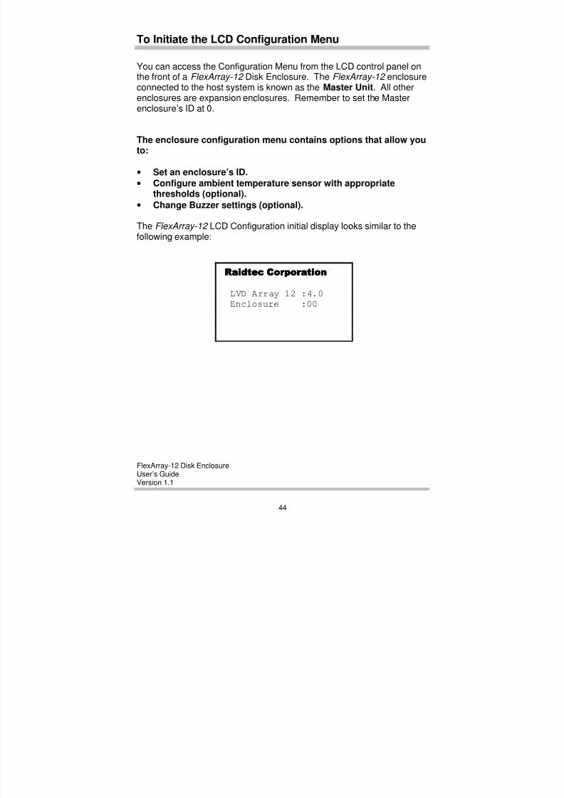
The FlexArray-12 LCD Configuration initial display looks similar to thefollowing example:
Raidtec CorporationRaidtec CorporationRaidtec CorporationRaidtec Corporation
LVD Array 12 :4.0
Enclosure :00

8/3/2019 Flex Array 12 Version 1.1
http://slidepdf.com/reader/full/flex-array-12-version-11 51/102
FlexArray-12 Disk EnclosureUser’s GuideVersion 1.1
45
C O R P O R A T I O N
Use the following instructions to initiate the Configuration UtilityMenu.
1. Power on the power switches at the rear of the FlexArray-12 enclosure. Power on both switches one immediately after the otherto avoid setting off the power supply alarm.
2. Press the Configuration button directly under the configuration iconto display the Enclosure Configuration Menu.
Configuration icon.
Enclosure Configuration->Enclosure ID
Sensor settings
Buzzer Settings
Hard AddressingExit
4. Press the UP/DOWN buttons to position the selection arrow next to
a menu option.
5. Press the ENTER < ┘ button to enter the menu option.
The EXIT option is the last option on the Enclosure Configuration Menu.
When you select EXIT, the Enclosure Configuration session ends andthe normal operating mode status displays.

8/3/2019 Flex Array 12 Version 1.1
http://slidepdf.com/reader/full/flex-array-12-version-11 52/102
FlexArray-12 Disk EnclosureUser’s GuideVersion 1.1
46
To Set an Enclosure ID
You can use the enclosure ID setting option to give a number value IDto a particular FlexArray-12 enclosure in a multiple enclosureconfiguration.
NOTE 1: The LCD Control Panel only configures the individual enclosure it is attached to.
NOTE 2: The Master Unit FlexArray-12 enclosure must be set to Enclosure ID 0. This enables serial port (SER 2)communication with the host system to run the RAIDmanLITE software.
Enclosure IDs must be unique. Do not assign the same ID to more than one enclosure.
Use the following instructions to set an enclosure ID.
1. Press the Configuration button to display the Enclosure
Configuration Menu, use the UP/DOWN buttons to position theselection arrow next to the Enclosure ID setting option.
Enclosure Configuration->Enclosure ID
Sensor settings
Buzzer SettingsHard Addressing
Exit

8/3/2019 Flex Array 12 Version 1.1
http://slidepdf.com/reader/full/flex-array-12-version-11 53/102
FlexArray-12 Disk EnclosureUser’s GuideVersion 1.1
47
C O R P O R A T I O N
2. Press the ENTER < ┘button to display the Enclosure ID Menu.
Enclosure ID MenuSelect Encl. ID
-> 0ENTER to proceed
3. Use the UP/DOWN buttons to scroll through the number options. Inthe case of the Master Unit enter the enclosure ID as 0.
4. Press the ENTER < ┘button to return to the Enclosure Configuration
Menu.
8/3/2019 Flex Array 12 Version 1.1
http://slidepdf.com/reader/full/flex-array-12-version-11 54/102
FlexArray-12 Disk EnclosureUser’s GuideVersion 1.1
48
To Enable Temperature Sensor Settings
The FlexArray-12 Environment Array Manager (EAM) contains sensorswhich measure enclosure temperature.
This option allows you to:
• Enable the temperature sensor.
• Set the ambient temperature threshold for enabled sensor.
NOTE: The temperature sensor is enabled by default in each FlexArray-12 enclosure.
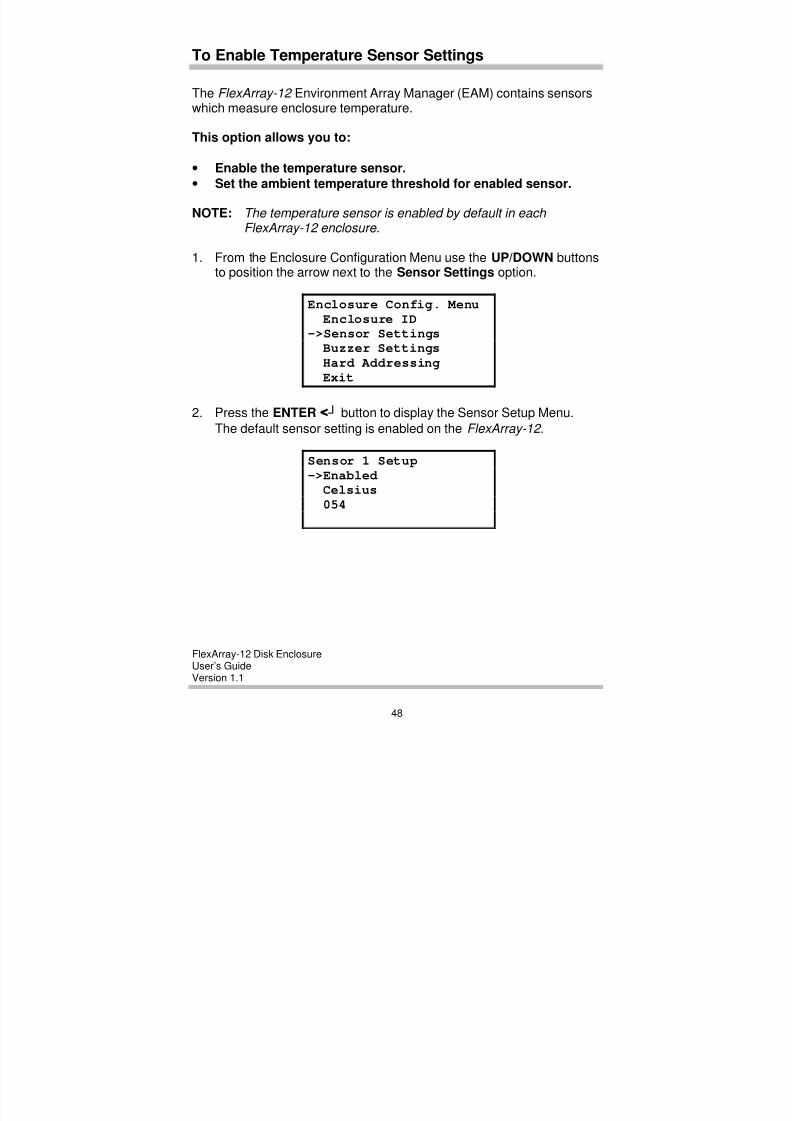
1. From the Enclosure Configuration Menu use the UP/DOWN buttonsto position the arrow next to the Sensor Settings option.
Enclosure Config. Menu
Enclosure ID->Sensor Settings
Buzzer Settings
Hard Addressing
Exit
2. Press the ENTER < ┘ button to display the Sensor Setup Menu.
The default sensor setting is enabled on the FlexArray-12 .
Sensor 1 Setup
->EnabledCelsius
054
8/3/2019 Flex Array 12 Version 1.1
http://slidepdf.com/reader/full/flex-array-12-version-11 55/102
FlexArray-12 Disk EnclosureUser’s GuideVersion 1.1
49
C O R P O R A T I O N
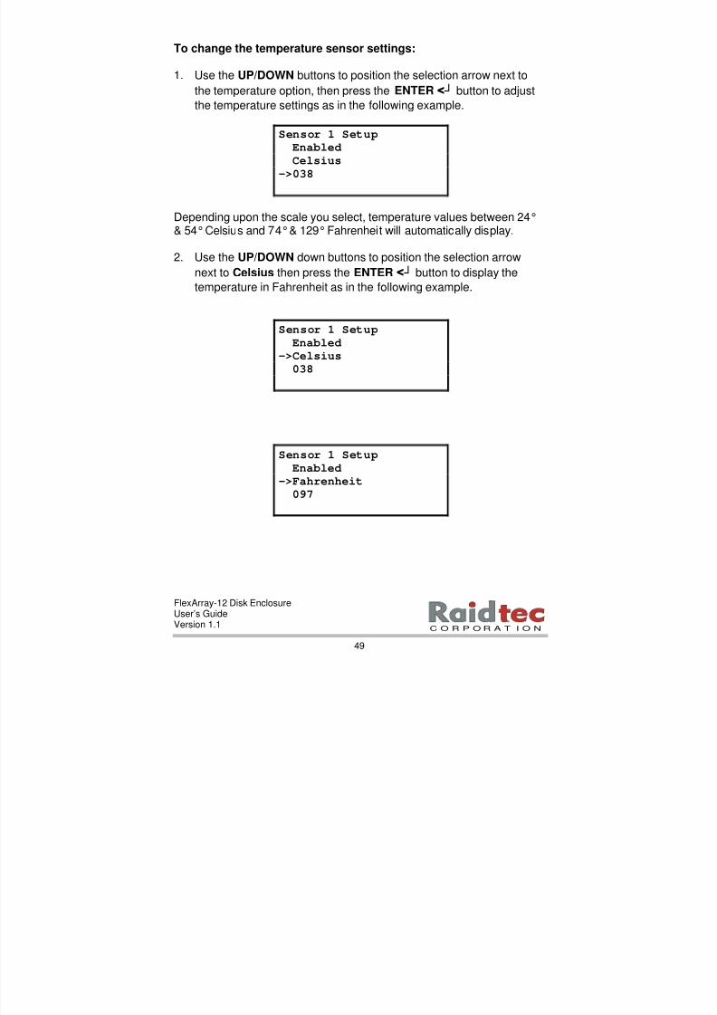
To change the temperature sensor settings:
1. Use the UP/DOWN buttons to position the selection arrow next to
the temperature option, then press the ENTER < ┘ button to adjust
the temperature settings as in the following example.
Sensor 1 SetupEnabled
Celsius
->038
Depending upon the scale you select, temperature values between 24°& 54° Celsius and 74° & 129° Fahrenheit will automatically display.
2. Use the UP/DOWN down buttons to position the selection arrow
next to Celsius then press the ENTER < ┘ button to display the
temperature in Fahrenheit as in the following example.
Sensor 1 Setup
Enabled
->Celsius038
Sensor 1 Setup
Enabled->Fahrenheit
097
8/3/2019 Flex Array 12 Version 1.1
http://slidepdf.com/reader/full/flex-array-12-version-11 56/102
FlexArray-12 Disk EnclosureUser’s GuideVersion 1.1
50
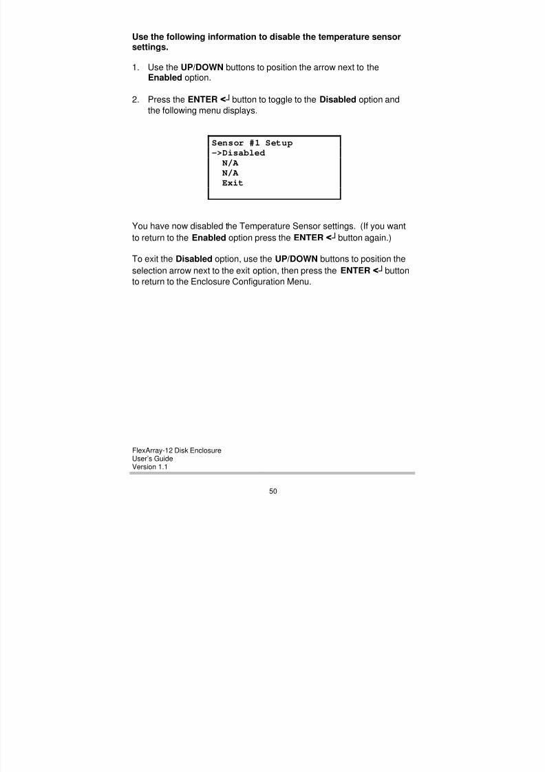
Use the following information to disable the temperature sensorsettings.
1. Use the UP/DOWN buttons to position the arrow next to theEnabled option.
2. Press the ENTER < ┘button to toggle to the Disabled option and
the following menu displays.
Sensor #1 Setup->Disabled
N/A N/A Exit
You have now disabled the Temperature Sensor settings. (If you want
to return to the Enabled option press the ENTER < ┘button again.)
To exit the Disabled option, use the UP/DOWN buttons to position the
selection arrow next to the exit option, then press the ENTER < ┘buttonto return to the Enclosure Configuration Menu.
8/3/2019 Flex Array 12 Version 1.1
http://slidepdf.com/reader/full/flex-array-12-version-11 57/102
FlexArray-12 Disk EnclosureUser’s GuideVersion 1.1
51
C O R P O R A T I O N
To Change Buzzer Settings
You can use the Buzzer Settings option to Enable or Disable the ErrorLog Alarm. The default setting for the Error Log Alarm is Enabled.When the Error Log Alarm is disabled, the alarm will no longer soundonly the Error Log Alarm icon displays on the LCD panel.
NOTE: Raidtec Corporation recommends maintaining the Error Log Alarm default settings on your FlexArray-12 enclosure.
1. From the Enclosure Configuration Menu, use the UP/DOWN buttons to position the selection arrow next the Buzzer Settings option.
Enclosure Config. MenuEnclosure IDSensor settings
->Buzzer settingsHard Addressing
Exit
2. Press the ENTER < ┘ button to display the following menu.
Buzzer Menu->Enable
Disable
3. On the Buzzer Menu, use the UP/DOWN arrows to position the
selection arrow next to the option you want to use. (The defaultsetting is Enable.)
Error Log Alarm Icon
8/3/2019 Flex Array 12 Version 1.1
http://slidepdf.com/reader/full/flex-array-12-version-11 58/102
FlexArray-12 Disk EnclosureUser’s GuideVersion 1.1
52
4. Then, press the ENTER <<<< ┘ ┘┘ ┘button to return to the Enclosure
Configuration Menu.
NOTE: If you select Disable , the Error Log Alarm will no longer sound when an error log is recorded, only the Error Log Alarm icon will display on the LCD panel.
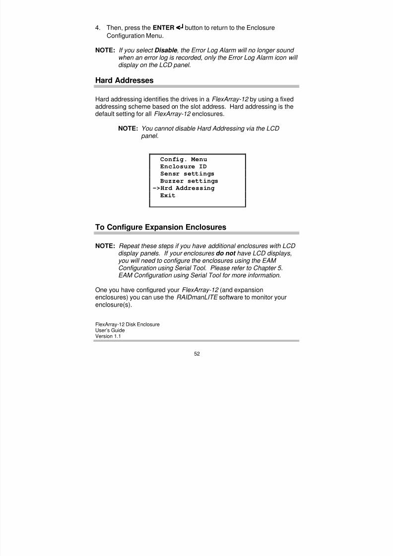
Hard Addresses
Hard addressing identifies the drives in a FlexArray-12 by using a fixedaddressing scheme based on the slot address. Hard addressing is thedefault setting for all FlexArray-12 enclosures.
NOTE: You cannot disable Hard Addressing via the LCD panel.
Config. MenuEnclosure IDSensr settings
Buzzer settings->Hrd Addressing
Exit
To Configure Expansion Enclosures
NOTE: Repeat these steps if you have additional enclosures with LCD display panels. If your enclosures do not have LCD displays,you will need to configure the enclosures using the EAM Configuration using Serial Tool . Please refer to Chapter 5.EAM Configuration using Serial Tool for more information.
One you have configured your FlexArray-12 (and expansionenclosures) you can use the RAIDmanLITE software to monitor yourenclosure(s).
8/3/2019 Flex Array 12 Version 1.1
http://slidepdf.com/reader/full/flex-array-12-version-11 59/102
FlexArray-12 Disk EnclosureUser’s GuideVersion 1.1
53
C O R P O R A T I O N
5. EAM CONFIGURATION USING SERIAL TOOL
This chapter provides information on the following functions usingthe EAM Configuration via Serial Tool software:
• How to configure your FlexArray-12 in instances whereFlexArray-12 enclosures do not have LCD panels.
• How to update the flash with a new version of the EAM firmwarecode in consultation with Raidtec Technical Support.
If you do not need to complete either of these functions, proceedto Chapter 6. RAIDmanLITE Software .
NOTE 1: In instances where your FlexArray-12 enclosures do not have LCD panels you need to configure enclosure IDs using the EAM Configuration Serial Tool.
NOTE 2: The Serial Tool is located on a 3.5” floppy diskette.
NOTE:3 When you configure enclosures via EAM Configuration using Serial Tool, take great care to configure enclosures IDs correctly. Raidtec recommends that you configure all enclosures in numerical order, beginning with enclosure (0),then enclosure (1), up to the maximum number of enclosures in a your enclosure configuration. It is also advisable that once you configure an enclosure ID, you also label each enclosure accordingly to avoid configuration errors.
Cable Connections
1. Connect the RS 232 cable from SER 2 on the FlexArray-12 to eitherCOM1 or COM 2 on your host system. Power on your host system.
8/3/2019 Flex Array 12 Version 1.1
http://slidepdf.com/reader/full/flex-array-12-version-11 60/102
FlexArray-12 Disk EnclosureUser’s GuideVersion 1.1
54
To Install Serial Tool onWindows 95/98 and Windows NT
1. Make a backup copy of the Serial Tool diskette. Use this backupcopy as your working diskette and retain the original in a safe place.
2. Start up Windows NT or Windows 95/98 on your host system.
3. Insert the EAM Configuration Serial Tool diskette into your 3.5”
disk drive.
4. Double click My Computer.
5. Double click on 3.5” floppy (A:).
6. Double click on SETUP.EXE to start the Serial Tool installation.
7. Click Next.
8. The screen displays a destination folder for Serial Tool. Click Next.
9. Select the components you want to install (SerialTool). Click Next.
10. SerialTool displays in the program section. Click Next, to installSerialTool.
11. A dialog box appears displaying the SerialTool icon. Click Finish on the main window.
Your installation of SerialTool is now complete.
8/3/2019 Flex Array 12 Version 1.1
http://slidepdf.com/reader/full/flex-array-12-version-11 61/102
FlexArray-12 Disk EnclosureUser’s GuideVersion 1.1
55
C O R P O R A T I O N
To Run EAM Configuration Serial Tool
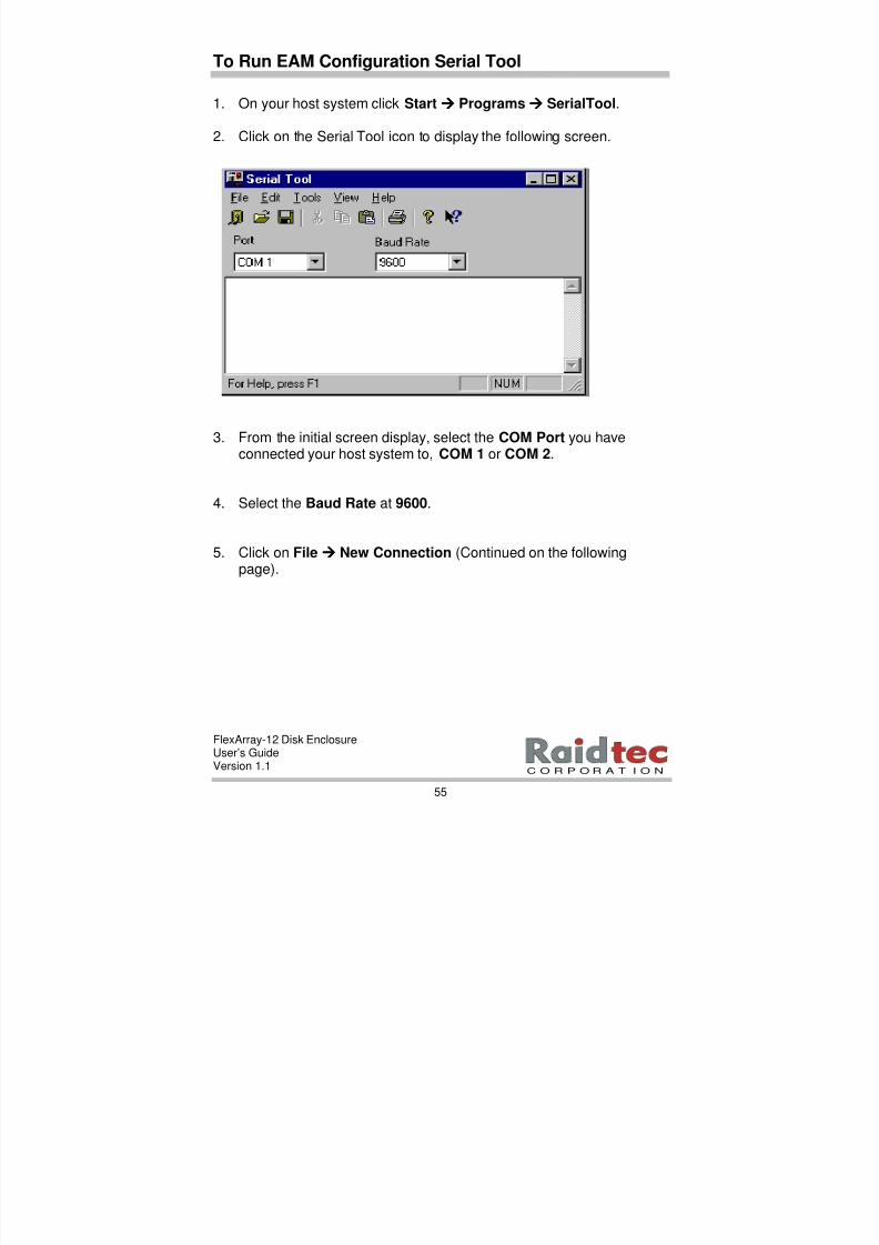
1. On your host system click Startàààà Programsàààà SerialTool.
2. Click on the Serial Tool icon to display the following screen.
3. From the initial screen display, select the COM Port you haveconnected your host system to, COM 1 or COM 2.
4. Select the Baud Rate at 9600.
5. Click on File àààà New Connection (Continued on the followingpage).
8/3/2019 Flex Array 12 Version 1.1
http://slidepdf.com/reader/full/flex-array-12-version-11 62/102
FlexArray-12 Disk EnclosureUser’s GuideVersion 1.1
56
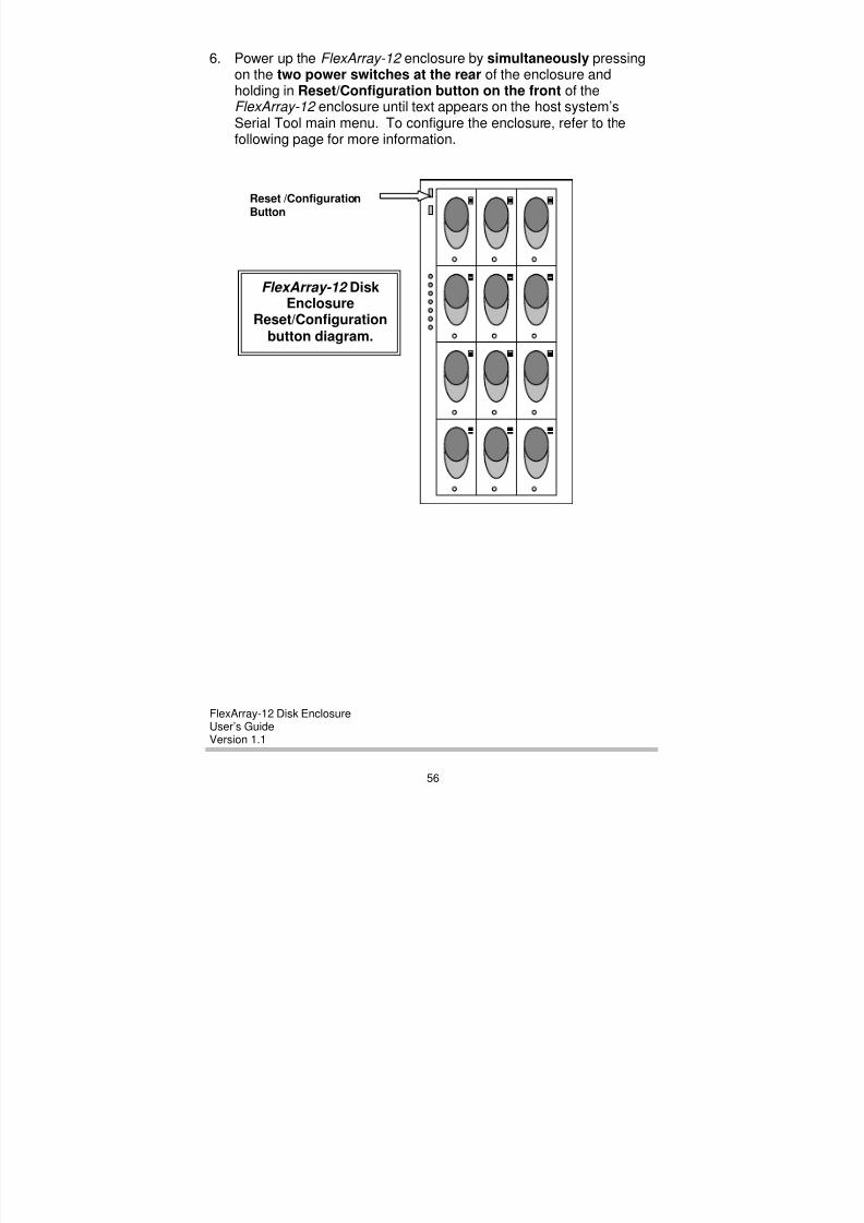
6. Power up the FlexArray-12 enclosure by simultaneously pressingon the two power switches at the rear of the enclosure andholding in Reset/Configuration button on the front of theFlexArray-12 enclosure until text appears on the host system’sSerial Tool main menu. To configure the enclosure, refer to thefollowing page for more information.
Reset /Configuration
Button
FlexArray-12 DiskEnclosure
Reset/Configurationbutton diagram.

8/3/2019 Flex Array 12 Version 1.1
http://slidepdf.com/reader/full/flex-array-12-version-11 63/102
FlexArray-12 Disk EnclosureUser’s GuideVersion 1.1
57
C O R P O R A T I O N
Enclosure Configuration
NOTE: Depending on how you configure your enclosure IDs; you can either accept or change the existing configuration settings. In most instances, you will need to change the enclosure configuration settings.
When you simultaneously press the power switches on the rear ofthe enclosure and hold in the Reset/Configuration button on the front
of the FlexArray-12 , text similar to the following appears on the SerialTool main menu. The main screen displays the currentenclosure/default configuration, similar to the following example.
Current/DefaultEnclosureConfigurationDisplay

8/3/2019 Flex Array 12 Version 1.1
http://slidepdf.com/reader/full/flex-array-12-version-11 64/102
FlexArray-12 Disk EnclosureUser’s GuideVersion 1.1
58
To Configure an Enclosure
To configure an enclosure you need to do the following:
1. Answer the, “Do you wish to change? (y/n)” section of the menu, bytyping y. The following prompt displays.
2. To configure an enclosure ID, type the number of the enclosurefrom numbers (0-7). The following prompt displays.
3. To enable temperature probe1, type y from (y/n). The followingprompt displays.
4. To enter the temperature threshold in degrees Celsius, type thetemperature threshold you want to use. You can selecttemperature values between 24° & 54° Celsius.
Example ofCurrent/DefaultEnclosureConfigurationDisplay

8/3/2019 Flex Array 12 Version 1.1
http://slidepdf.com/reader/full/flex-array-12-version-11 65/102
FlexArray-12 Disk EnclosureUser’s GuideVersion 1.1
59
C O R P O R A T I O N
5. You have now configured your enclosure. You are asked if youwant to upgrade the flash. Type n.
NOTE: You only use the Upgrade Flash option if you want to update the flash with a new version of the firmware code. If you want to upgrade the flash, refer to the upgrade flash section on the following page and contact Raidtec Technical Support for more information.
6. When you have completed all the configuration requests the word”Finished ”.
7. From the main menu select Fileàààà Exit to exit the application.
8. For enclosure (0) remove the RS 232 cable from the SER 2 serialport on the FlexArray-12 enclosure and connect it to the SER 2serial port on the next expansion enclosure (enclosure 1) in theconfiguration.
9. When you have configured all the enclosures in the configuration,disconnect the RS 232 cable from SER 2 on the last expansionenclosure (enclosure 1 ) in your configuration and reconnect theRS 232 cable to SER 2 on enclosure 0 to run the RAIDmanLITE
software.
10. Check that there is an RS 485 terminator to SER 4 on the lastenclosure in your configuration.

8/3/2019 Flex Array 12 Version 1.1
http://slidepdf.com/reader/full/flex-array-12-version-11 66/102
FlexArray-12 Disk EnclosureUser’s GuideVersion 1.1
60
To Upgrade the Flash
NOTE: Use this option when you need to Upgrade the FlashONLY!
NOTE: Consult Raidtec Technical Support for more information on Upgrading Flash.
If you want to update the flash with a new version of the EAM firmwarecode, you will need to upgrade the Flash.
1. On the main menu screen, you are asked, “Do you want to Upgradethe Flash?” If you need to update the Flash type, “Y”.
2. Once you type “Y”, downloading begins and a progress bar displayson the screen. The progress bar disappears once the download iscomplete and a “transfer complete” message appears on the
screen.
3. Press Enter to continue.

8/3/2019 Flex Array 12 Version 1.1
http://slidepdf.com/reader/full/flex-array-12-version-11 67/102
FlexArray-12 Disk EnclosureUser’s GuideVersion 1.1
61
C O R P O R A T I O N
4. You then have the following option, “Change boot options? (y/n)”
5. To change boot options type “Y”, this allows you to upgrade theEAM firmware code to the Flash Prom.
The next option to display is boot (0/1).
• 0 denotes the factory fitted prom.
• 1 denotes the upgrade prom.
6. Type in 1 to upgrade the prom with the new version of the EAMfirmware code.
7. From the Main menu select Fileàààà Exit to exit the application.
8. For enclosure (0) remove the RS 232 cable from the SER 2 serialport on the FlexArray-12 enclosure and connect it to the SER 2serial port on the next expansion enclosure (enclosure 1 ) in yourconfiguration.
9. When you have configured all the enclosures in the configuration,
disconnect the RS 232 cable from SER 2 on the last expansionenclosure in your configuration and reconnect the RS 232 cable toSER 2 on enclosure 0 (FlexArray-12 ) to run RAIDmanLITE software.
8/3/2019 Flex Array 12 Version 1.1
http://slidepdf.com/reader/full/flex-array-12-version-11 68/102

8/3/2019 Flex Array 12 Version 1.1
http://slidepdf.com/reader/full/flex-array-12-version-11 69/102
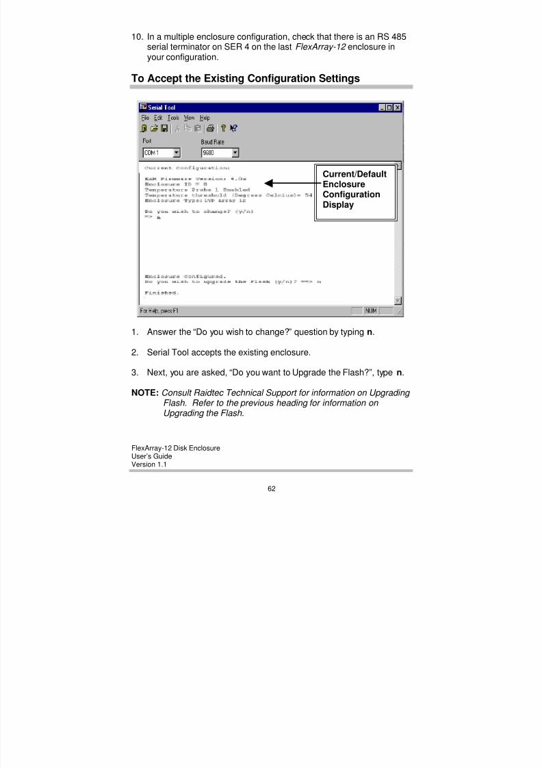
FlexArray-12 Disk EnclosureUser’s GuideVersion 1.1
63
C O R P O R A T I O N
When you accept the existing enclosure configuration. The EAMcontinues with normal operations.
4. From the main menu, select File àààà Exit to exit the application.
5. For enclosure (0) remove the RS 232 cable from the SER 2 serialport on the FlexArray-12 enclosure and connect it to theSER 2 serial port on the next expansion enclosure, (enclosure 1) inyour configuration.
6. When you have configured all the enclosures in your configuration,disconnect the RS 232 cable from SER 2 on the last expansionenclosure (FlexArray-12) in your configuration and reconnect theRS 232 cable to SER 2 on enclosure 0 (FlexArray-12 ) to runRAIDmanLITE software.
7. In a multiple enclosure configuration, check that there is an RS 485terminator on SER 4 on the last FlexArray-12 enclosure in yourconfiguration.

8/3/2019 Flex Array 12 Version 1.1
http://slidepdf.com/reader/full/flex-array-12-version-11 70/102
FlexArray-12 Disk EnclosureUser’s GuideVersion 1.1
64
6. RAIDMANLITE SOFTWARE
This chapter provides information on how to:
• Install and run the FlexArray-12 .
• Use RAIDmanLITE to monitor the FlexArray-12 .
The RAIDmanLITE administration software provides a 32-bit, Windows
compatible GUI for FlexArray-12 enclosure configuration,administration, and alert notification. This utility is available foroperation in both Windows 95/98 and Windows NT environments.
You can use RAIDmanLITE to monitor the following:
• Disk drive presence.
• Enclosure temperature readings.
• Power supply and fan status.
• Alarm history log.
You can use RAIDmanLITE to complete the following functions:
• Enable temperature sensor.• Set temperature threshold alerts.
RAIDmanLITE System Requirements
To run RAIDmanLITE you will need the following:
System Component Specifications
Computer PC with minimum processor, clock speed, andRAM as required by operating system.
Operating System Windows 95
Windows NT 3.51 & 4.xCable Null modem
8/3/2019 Flex Array 12 Version 1.1
http://slidepdf.com/reader/full/flex-array-12-version-11 71/102
FlexArray-12 Disk EnclosureUser’s GuideVersion 1.1
65
C O R P O R A T I O N
To Connect Cables
1. Connect an RS 232 cable from SER 2 on the FlexArray-12 diskenclosure 0 (Master Unit) to a serial port on the host system where RAIDmanLITE will be running.
2. Check that all remaining cables are intact that terminators are inplace on the SCSI 3 and SCSI 4 if you are using a two channelsubsystem) and that an RS 485 terminator is in place on SER 4 on
the last enclosure in a multiple enclosure configuration.
To Install RAIDmanLITE on Windows95/98 andWindows NT
RAIDmanLITE is provided on a 3.5” diskette, that contains theprograms necessary for installation in Windows and Windows NTenvironments.
1. Make a backup copy of the RAIDmanLITE diskette. Use thisbackup copy as your working diskette and retain the original in asafe place.
2. Start up Windows NT or Windows 95/98 on your host computer.
3. Insert the RAIDmanLITE diskette into your 3.5” disk drive now.
4. Double click My Computer.
5. Double click on 3.5” floppy (A:).
6. Double click on SETUP.EXE to start the RAIDmanLITE installation.Click Next.
7. A RAIDman icon displays in a destination folder. Click Next.
8. Select the components you want to install. Click Next.
9. RAIDman appears in the Programs folder. Click Next.

8/3/2019 Flex Array 12 Version 1.1
http://slidepdf.com/reader/full/flex-array-12-version-11 72/102
FlexArray-12 Disk EnclosureUser’s GuideVersion 1.1
66
10. A RAIDman icon appears on the screen. Click Finish.
Your installation of RAIDmanLITE is now complete.
To Run RAIDmanLITE
• Power up the FlexArray-12 enclosure. Wait for self-test tocomplete.
• Click Startàààà Programsàààà RAIDmanLITE .
Main Control Panel
The RAIDmanLITE Main Control Panel provides all the information onthe current status of the FlexArray-12 enclosure(s).
The Main Control Panel screen includes the following information:
• Disk drive presence.
• Enclosure temperature readings.
• Power Supply and Fan status.
•
Alarm history log.
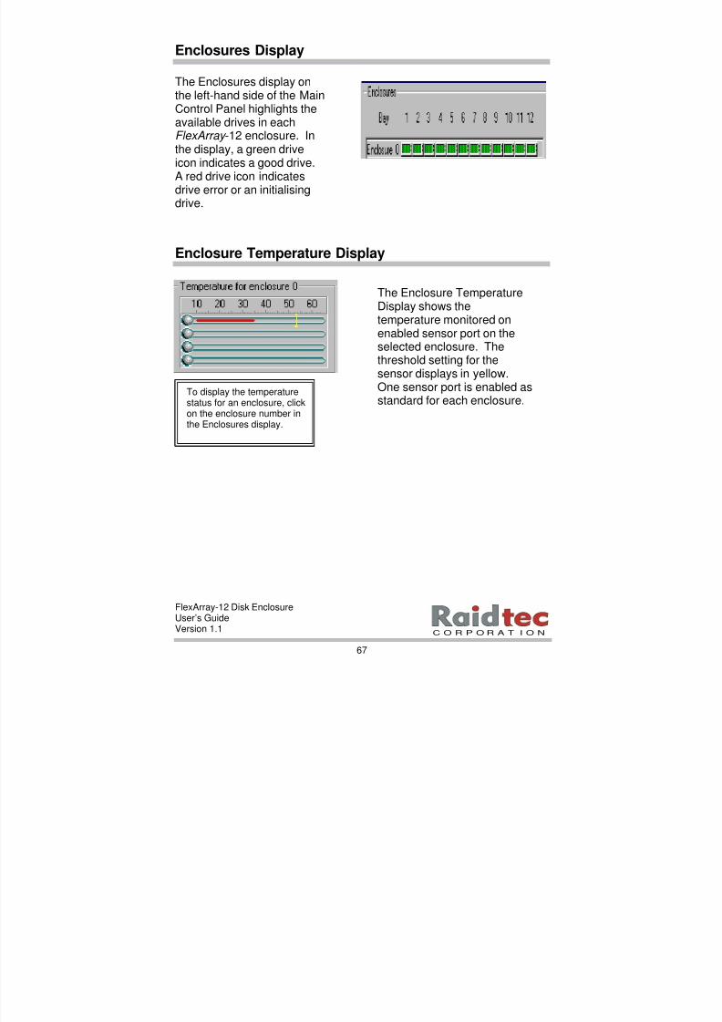
8/3/2019 Flex Array 12 Version 1.1
http://slidepdf.com/reader/full/flex-array-12-version-11 73/102
FlexArray-12 Disk EnclosureUser’s GuideVersion 1.1
67
C O R P O R A T I O N
Enclosures Display
Enclosure Temperature Display
The Enclosure TemperatureDisplay shows thetemperature monitored onenabled sensor port on theselected enclosure. The
threshold setting for thesensor displays in yellow.One sensor port is enabled asstandard for each enclosure.
To display the temperaturestatus for an enclosure, clickon the enclosure number inthe Enclosures display.
The Enclosures display onthe left-hand side of the MainControl Panel highlights theavailable drives in eachFlexArray -12 enclosure. Inthe display, a green driveicon indicates a good drive.
A red drive icon indicatesdrive error or an initialisingdrive.
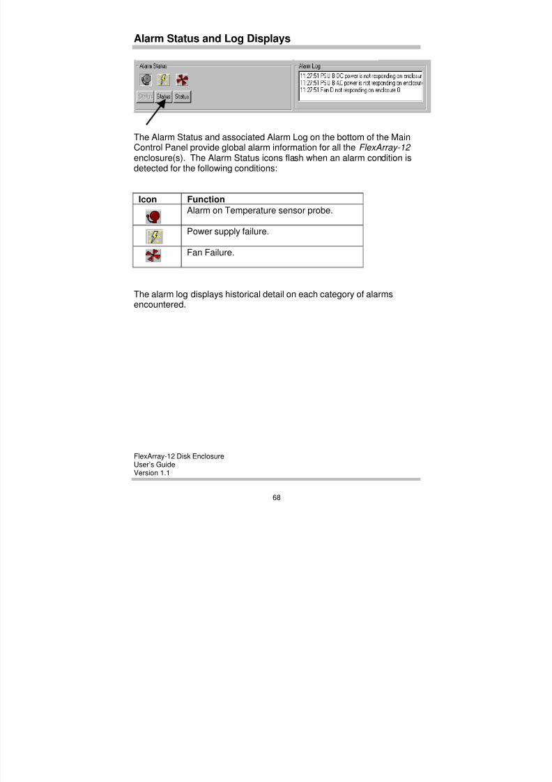
8/3/2019 Flex Array 12 Version 1.1
http://slidepdf.com/reader/full/flex-array-12-version-11 74/102
FlexArray-12 Disk EnclosureUser’s GuideVersion 1.1
68
Alarm Status and Log Displays
To view details on any of the alarms, point and click on the STATUS button below the alarm icon.
The Alarm Status and associated Alarm Log on the bottom of the MainControl Panel provide global alarm information for all the FlexArray-12 enclosure(s). The Alarm Status icons flash when an alarm condition isdetected for the following conditions:
Icon Function
Alarm on Temperature sensor probe.
Power supply failure.
Fan Failure.
The alarm log displays historical detail on each category of alarmsencountered.
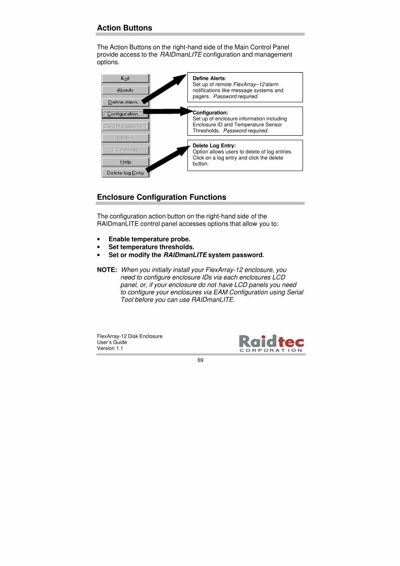
8/3/2019 Flex Array 12 Version 1.1
http://slidepdf.com/reader/full/flex-array-12-version-11 75/102
FlexArray-12 Disk EnclosureUser’s GuideVersion 1.1
69
C O R P O R A T I O N
Action Buttons
The Action Buttons on the right-hand side of the Main Control Panelprovide access to the RAIDmanLITE configuration and managementoptions.
Enclosure Configuration Functions
The configuration action button on the right-hand side of theRAIDmanLITE control panel accesses options that allow you to:
• Enable temperature probe.
• Set temperature thresholds.
• Set or modify the RAIDmanLITE system password.
NOTE: When you initially install your FlexArray-12 enclosure, you need to configure enclosure IDs via each enclosures LCD panel, or, if your enclosure do not have LCD panels you need to configure your enclosures via EAM Configuration using Serial
Tool before you can use RAIDmanLITE.
Define Alerts:Set up of remote FlexArray–12 alarmnotifications like message systems and
pagers. Password required.
Configuration:Set up of enclosure information includingEnclosure ID and Temperature SensorThresholds. Password required.
Delete Log Entry:Option allows users to delete of log entries.Click on a log entry and click the deletebutton.

8/3/2019 Flex Array 12 Version 1.1
http://slidepdf.com/reader/full/flex-array-12-version-11 76/102
FlexArray-12 Disk EnclosureUser’s GuideVersion 1.1
70
To Configure an Enclosures Sensors
3. Enter the RAIDmanLITE system password.
NOTE: There is no default system password .
4. Enter the correct system password, then click OK to display theConfiguration for Enclosure screen.
1. Click on the enclosurenumber on theEnclosures display.
2. Click on theConfiguration actionbutton.

8/3/2019 Flex Array 12 Version 1.1
http://slidepdf.com/reader/full/flex-array-12-version-11 77/102
FlexArray-12 Disk EnclosureUser’s GuideVersion 1.1
71
C O R P O R A T I O N
To Enable Temperature Sensor
1. From the Sensor options menu, select Enable. Click OK.
2. You can use the Trigger scrollbars to select an appropriatetemperature threshold for each enabled sensor. Depending on theTemperature scale you select, temperature values between24˚-54˚ Celsius and 74˚-129˚ Fahrenheit display.
NOTE: Sensor #1 is installed by default in each FlexArray-12 enclosure.
To Set or Modify the System Password
You can set or modify the system password from the password actionbutton on the Configuration for Enclosure screen.
NOTE: There is no default system password. Due to the sensitive nature of some of the RAIDmanLITE-12 features, Raidtec highly recommends you set a system password.
To Set or Modify the System Password
1. From the Configuration for enclosure menu, click on the passwordbutton to display the following screen.
2. Enter the password you want to use, enter it again for verification.Click OK. You have now set a new system password.
When you set or modify a system password, remember to make anote of it and keep it secure!
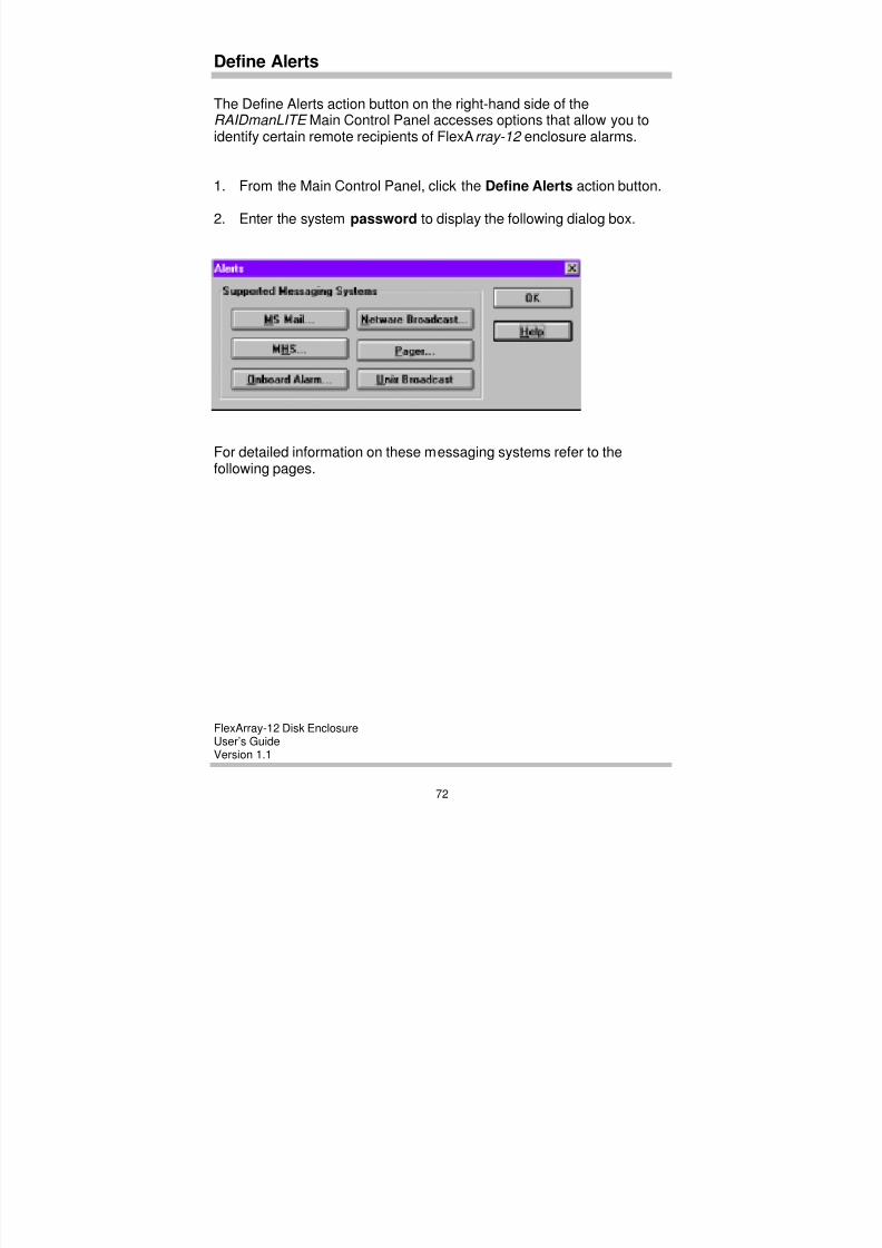
8/3/2019 Flex Array 12 Version 1.1
http://slidepdf.com/reader/full/flex-array-12-version-11 78/102
FlexArray-12 Disk EnclosureUser’s GuideVersion 1.1
72
Define Alerts
The Define Alerts action button on the right-hand side of theRAIDmanLITE Main Control Panel accesses options that allow you toidentify certain remote recipients of FlexArray-12 enclosure alarms.
1. From the Main Control Panel, click the Define Alerts action button.
2. Enter the system password to display the following dialog box.
For detailed information on these messaging systems refer to thefollowing pages.
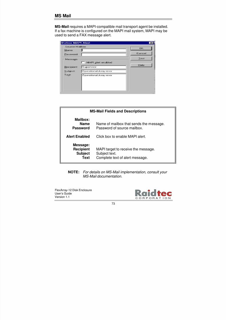
8/3/2019 Flex Array 12 Version 1.1
http://slidepdf.com/reader/full/flex-array-12-version-11 79/102
FlexArray-12 Disk EnclosureUser’s GuideVersion 1.1
73
C O R P O R A T I O N
MS Mail
MS-Mail requires a MAPI-compatible mail transport agent be installed.If a fax machine is configured on the MAPI mail system, MAPI may beused to send a FAX message alert.
NOTE: For details on MS-Mail implementation, consult your MS-Mail documentation.
MS-Mail Fields and Descriptions
Mailbox:Name Name of mailbox that sends the message.
Password Password of source mailbox.
Alert Enabled Click box to enable MAPI alert.
Message:Recipient MAPI target to receive the message.
Subject Subject text.Text Complete text of alert message.
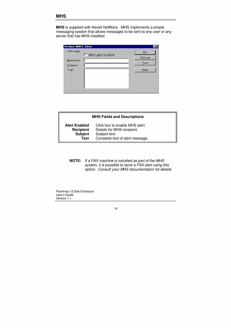
8/3/2019 Flex Array 12 Version 1.1
http://slidepdf.com/reader/full/flex-array-12-version-11 80/102
FlexArray-12 Disk EnclosureUser’s GuideVersion 1.1
74
MHS
MHS is supplied with Novell NetWare. MHS implements a simplemessaging system that allows messages to be sent to any user or anyserver that has MHS installed.
NOTE: If a FAX machine is installed as part of the MHS system, it is possible to send a FAX alert using this option. Consult your MHS documentation for details.
MHS Fields and Descriptions
Alert Enabled Click box to enable MHS alert.Recipient Details for MHS recipient.
Subject Subject text.Text Complete text of alert message.
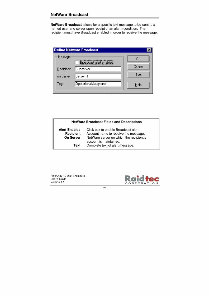
8/3/2019 Flex Array 12 Version 1.1
http://slidepdf.com/reader/full/flex-array-12-version-11 81/102
FlexArray-12 Disk EnclosureUser’s GuideVersion 1.1
75
C O R P O R A T I O N
NetWare Broadcast
NetWare Broadcast allows for a specific text message to be sent to anamed user and server upon receipt of an alarm condition. Therecipient must have Broadcast enabled in order to receive the message.
NetWare Broadcast Fields and Descriptions
Alert Enabled Click box to enable Broadcast alert. Recipient Account name to receive the message.On Server NetWare server on which the recipient’s
account is maintained.Text Complete text of alert message.
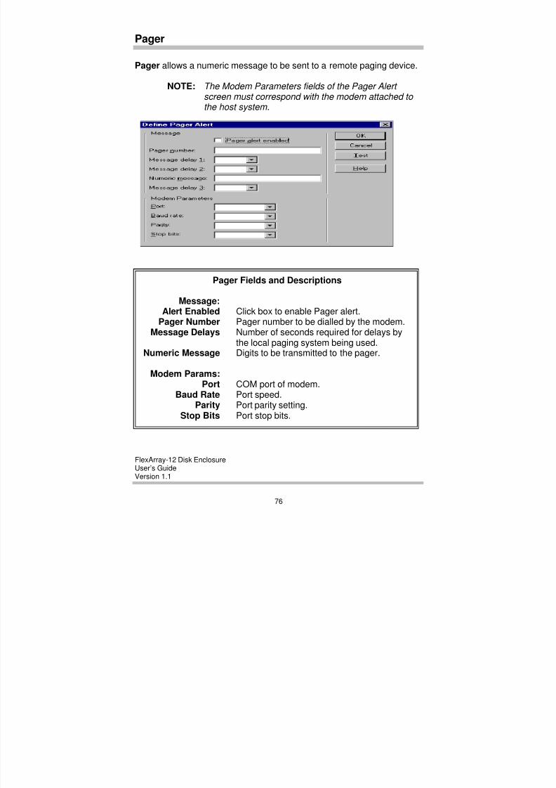
8/3/2019 Flex Array 12 Version 1.1
http://slidepdf.com/reader/full/flex-array-12-version-11 82/102
FlexArray-12 Disk EnclosureUser’s GuideVersion 1.1
76
Pager
Pager allows a numeric message to be sent to a remote paging device.
NOTE: The Modem Parameters fields of the Pager Alert screen must correspond with the modem attached to the host system.
Pager Fields and Descriptions
Message:Alert Enabled Click box to enable Pager alert.
Pager Number Pager number to be dialled by the modem.Message Delays Number of seconds required for delays by
the local paging system being used.Numeric Message Digits to be transmitted to the pager.
Modem Params:Port COM port of modem.
Baud Rate Port speed.Parity Port parity setting.
Stop Bits Port stop bits.
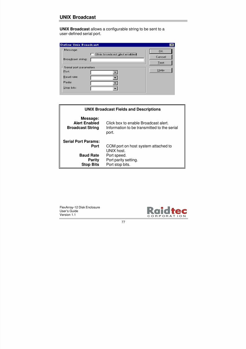
8/3/2019 Flex Array 12 Version 1.1
http://slidepdf.com/reader/full/flex-array-12-version-11 83/102
FlexArray-12 Disk EnclosureUser’s GuideVersion 1.1
77
C O R P O R A T I O N
UNIX Broadcast
UNIX Broadcast allows a configurable string to be sent to auser-defined serial port.
UNIX Broadcast Fields and Descriptions
Message:
Alert Enabled Click box to enable Broadcast alert. Broadcast String Information to be transmitted to the serial
port.
Serial Port Params:Port COM port on host system attached to
UNIX host.Baud Rate Port speed.
Parity Port parity setting.Stop Bits Port stop bits.

8/3/2019 Flex Array 12 Version 1.1
http://slidepdf.com/reader/full/flex-array-12-version-11 84/102
FlexArray-12 Disk EnclosureUser’s GuideVersion 1.1
78
NOTE:This option can be used when the RAIDmanLITE host system is connected via serial protocol to a UNIX serial port that is accepting input. The broadcast string defines a command that is to be executed on the UNIX host.
A sample string might be:“Please check the FlexArray-12 in Accounts Receivable Department for status change.”
The broadcast string will be read by a daemon configured to monitor the serial port and redirect the incoming message to an administrator or support mailbox.
8/3/2019 Flex Array 12 Version 1.1
http://slidepdf.com/reader/full/flex-array-12-version-11 85/102
FlexArray-12 Disk EnclosureUser’s GuideVersion 1.1
79
C O R P O R A T I O N
7. TROUBLESHOOTING
This chapter provides troubleshooting information for the FlexArray-12 under the following headings:
• Setup issues action list.
• Enclosure ID problems.
• Power-up problems.
• Setup problems.• Enclosure or Drive Errors.
FlexArray-12 enclosure provides error reporting and event notificationinformation via a number of sources including:
• RAIDmanLITE GUI event notification.
• FlexArray-12 enclosure audible alarms.
• FlexArray-12 enclosure LED indicators and LCD messages onthe front control panel.
• Error Alarm Log on the LCD panel.
NOTE: If above diagnostic sources do not operate, the problem is likely
at the AC input level. Check power connections and fuses accordingly and verify the power supply units in the enclosure(s) are properly seated.
8/3/2019 Flex Array 12 Version 1.1
http://slidepdf.com/reader/full/flex-array-12-version-11 86/102
FlexArray-12 Disk EnclosureUser’s GuideVersion 1.1
80
Setup Issues Action List
The following action list contains ideas for resolving problemsassociated with drives not being found. These problems can ariseduring the initial setup of your FlexArray-12 Disk Enclosure.
ü Verify all drives are installed and power is applied by checking theFlexArray-12 disk drive indicator LEDs. Green LEDs should beconstantly lit when a drive is installed in the FlexArray-12 enclosure.
NOTE: The LCD panel should be in the initial menu display in order to verify LEDs correctly.
ü Verify the FlexArray-12 enclosures are configured correctly.
NOTE: The enclosure connected to the host system via SER 2 (Master Unit) must be Enclosure ID=0 and each subsequent enclosure must have a unique, sequential ID.
ü Verify the FlexArray-12 enclosures are cabled correctly.
ü Verify that there are terminators on SCSI 4(and on SCSI 3 and
SCSI 4 for two channel enclosures). Verify that there is aterminator on SER 4 on the last enclosure in a multiple enclosureconfiguration.
ü If there are no obvious drive or cabling problems, consult yourRaidtec supplier.
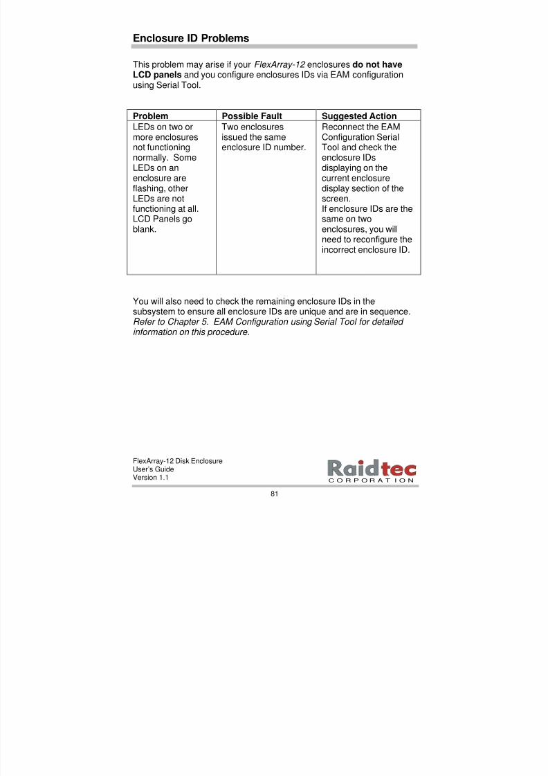
8/3/2019 Flex Array 12 Version 1.1
http://slidepdf.com/reader/full/flex-array-12-version-11 87/102
FlexArray-12 Disk EnclosureUser’s GuideVersion 1.1
81
C O R P O R A T I O N
Enclosure ID Problems
This problem may arise if your FlexArray-12 enclosures do not haveLCD panels and you configure enclosures IDs via EAM configurationusing Serial Tool.
Problem Possible Fault Suggested Action
LEDs on two or
more enclosuresnot functioningnormally. SomeLEDs on anenclosure areflashing, otherLEDs are notfunctioning at all.LCD Panels goblank.
Two enclosures
issued the sameenclosure ID number.
Reconnect the EAM
Configuration SerialTool and check theenclosure IDsdisplaying on thecurrent enclosuredisplay section of thescreen.If enclosure IDs are thesame on twoenclosures, you willneed to reconfigure theincorrect enclosure ID.
You will also need to check the remaining enclosure IDs in thesubsystem to ensure all enclosure IDs are unique and are in sequence.Refer to Chapter 5. EAM Configuration using Serial Tool for detailed information on this procedure.
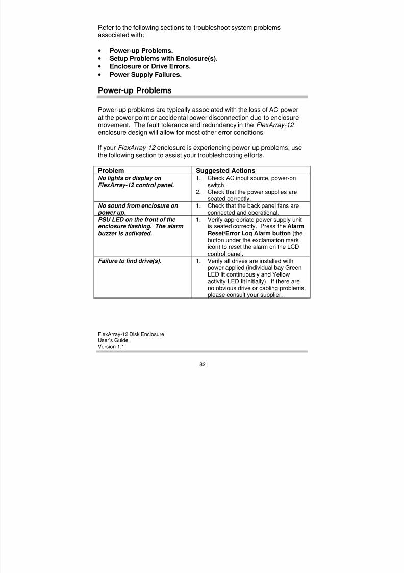
8/3/2019 Flex Array 12 Version 1.1
http://slidepdf.com/reader/full/flex-array-12-version-11 88/102
FlexArray-12 Disk EnclosureUser’s GuideVersion 1.1
82
Refer to the following sections to troubleshoot system problemsassociated with:
• Power-up Problems.
• Setup Problems with Enclosure(s).
• Enclosure or Drive Errors.
• Power Supply Failures.
Power-up Problems
Power-up problems are typically associated with the loss of AC powerat the power point or accidental power disconnection due to enclosuremovement. The fault tolerance and redundancy in the FlexArray-12 enclosure design will allow for most other error conditions.
If your FlexArray-12 enclosure is experiencing power-up problems, usethe following section to assist your troubleshooting efforts.
Problem Suggested ActionsNo lights or display on FlexArray-12 control panel.
1. Check AC input source, power-onswitch.
2. Check that the power supplies are
seated correctly.No sound from enclosure on power up .
1. Check that the back panel fans areconnected and operational.
PSU LED on the front of the enclosure flashing. The alarm buzzer is activated.
1. Verify appropriate power supply unitis seated correctly. Press the AlarmReset/Error Log Alarm button (thebutton under the exclamation markicon) to reset the alarm on the LCDcontrol panel.
Failure to find drive(s). 1. Verify all drives are installed withpower applied (individual bay GreenLED lit continuously and Yellowactivity LED lit initially). If there areno obvious drive or cabling problems,please consult your supplier.
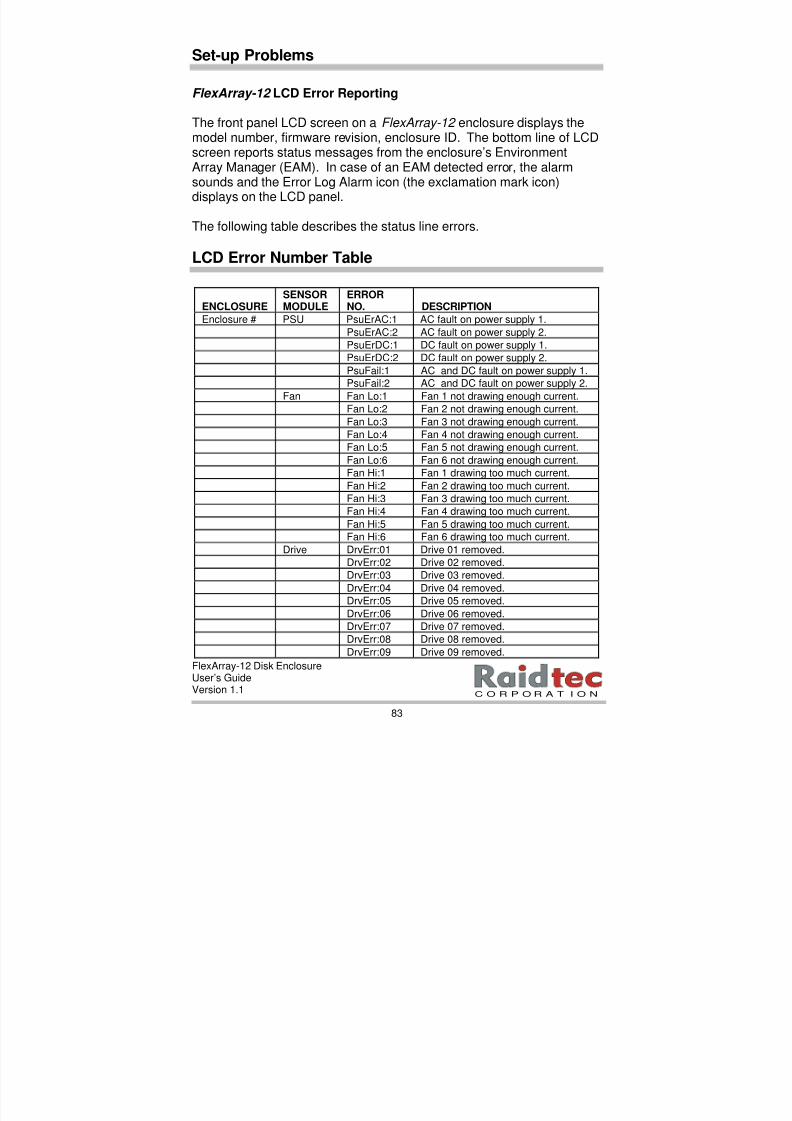
8/3/2019 Flex Array 12 Version 1.1
http://slidepdf.com/reader/full/flex-array-12-version-11 89/102
FlexArray-12 Disk EnclosureUser’s GuideVersion 1.1
83
C O R P O R A T I O N
Set-up Problems
FlexArray-12 LCD Error Reporting
The front panel LCD screen on a FlexArray-12 enclosure displays themodel number, firmware revision, enclosure ID. The bottom line of LCDscreen reports status messages from the enclosure’s EnvironmentArray Manager (EAM). In case of an EAM detected error, the alarmsounds and the Error Log Alarm icon (the exclamation mark icon)
displays on the LCD panel.
The following table describes the status line errors.
LCD Error Number Table
ENCLOSURESENSORMODULE
ERRORNO. DESCRIPTION
Enclosure # PSU PsuErAC:1 AC fault on power supply 1.
PsuErAC:2 AC fault on power supply 2.
PsuErDC:1 DC fault on power supply 1.
PsuErDC:2 DC fault on power supply 2.
PsuFail:1 AC and DC fault on power supply 1.
PsuFail:2 AC and DC fault on power supply 2.
Fan Fan Lo:1 Fan 1 not drawing enough current.Fan Lo:2 Fan 2 not drawing enough current.
Fan Lo:3 Fan 3 not drawing enough current.
Fan Lo:4 Fan 4 not drawing enough current.
Fan Lo:5 Fan 5 not drawing enough current.
Fan Lo:6 Fan 6 not drawing enough current.
Fan Hi:1 Fan 1 drawing too much current.
Fan Hi:2 Fan 2 drawing too much current.
Fan Hi:3 Fan 3 drawing too much current.
Fan Hi:4 Fan 4 drawing too much current.
Fan Hi:5 Fan 5 drawing too much current.
Fan Hi:6 Fan 6 drawing too much current.
Drive DrvErr:01 Drive 01 removed.
DrvErr:02 Drive 02 removed.
DrvErr:03 Drive 03 removed.
DrvErr:04 Drive 04 removed.DrvErr:05 Drive 05 removed.
DrvErr:06 Drive 06 removed.
DrvErr:07 Drive 07 removed.
DrvErr:08 Drive 08 removed.
DrvErr:09 Drive 09 removed.

8/3/2019 Flex Array 12 Version 1.1
http://slidepdf.com/reader/full/flex-array-12-version-11 90/102
FlexArray-12 Disk EnclosureUser’s GuideVersion 1.1
84
DrvErr:10 Drive 10 removed.
DrvErr:11 Drive 11 removed.
DrvErr:12 Drive 12 removed.
Temp TmpErr:01 Sensor 1 Temperature limitexceeded.
TmpErr:02 Sensor 1 Temperature limitexceeded.
TmpErr:03 Sensor 1 Temperature limitexceeded.
TmpErr:04 Sensor 1 Temperature limitexceeded.
The following example indicates a fault with a power supply unit. Suchan error would also sound an audible alarm, display the Error Alarm Logicon on the LCD Panel and display an error message on theRAIDmanLITE software.
The following is an example on a PSU error displaying on the LCDpanel Error Alarm Log Error State Menu.
En Error State00 PsuEr DC:1 *Act*Exit
To halt the alarm you need to press the Alarm Reset / Error Log Alarmbutton the button under the Alarm Reset/Error Log Alarm (exclamationmark) icon on the LCD panel. For instructions on how to quiet thealarm, via the LCD panel, please refer to Chapter 5. Subsystem Configuration; To Quiet the Error Log Alarm.
8/3/2019 Flex Array 12 Version 1.1
http://slidepdf.com/reader/full/flex-array-12-version-11 91/102
FlexArray-12 Disk EnclosureUser’s GuideVersion 1.1
85
C O R P O R A T I O N
Enclosure or Drive Errors
If your FlexArray-12 enclosure is displaying failure messages or alarmconditions, use the following section to assist your troubleshootingefforts.
Drive Failure
NOTE: The FlexArray-12 enclosure can be set up to operate in fault tolerant modes. However, Raidtec strongly recommends you make valid system backups regularly to keep your system failure safe.
Disk failure is indicated in the RAIDmanLITE software by theappropriate alert notification and a Red drive indication.
There are several things that could cause a drive failure:
1. Physically removing a drive from the FlexArray-12 enclosure.2. A non-recoverable read/write error on a hard disk.3. A non-recoverable hardware error.
NOTE: DO NOT remove a disk drive from a FlexArray-12 enclosure while the enclosure is operating. In a real environment, this could result in data loss.
What to do if a Drive Fails
1. Select the Mute Beeper option in the RAIDmanLITE software (orhalt the alarm using the Alarm Reset/Error Log Alarm button on theLCD panel) to quiet the beeper, if required.
2. Always replace a failing drive with a new or thoroughly tested one.DO NOT troubleshoot a failing drive in the RAIDmanLITE software .
REMEMBER! Always use a new spare drive to replace the failed drive. Use another PC system to troubleshoot a failed drive or return it to the manufacturer to have it checked out, fixed or replaced.

8/3/2019 Flex Array 12 Version 1.1
http://slidepdf.com/reader/full/flex-array-12-version-11 92/102
FlexArray-12 Disk EnclosureUser’s GuideVersion 1.1
86
Raidtec Technical Support
If you have any questions, problems, or suggestions, you can reachRaidtec Technical Support in any of the following ways:
Raidtec Corporation (USA) Raidtec Corporation (Europe)
By email. [email protected] [email protected] By telephone. (770) 664-6066 +353-21-353440
By FAX. (770) 664-6166 +353-21-353799
8/3/2019 Flex Array 12 Version 1.1
http://slidepdf.com/reader/full/flex-array-12-version-11 93/102
FlexArray-12 Disk EnclosureUser’s GuideVersion 1.1
87
C O R P O R A T I O N
GLOSSARY
ANSI: American National Standards Institute. A standardsdevelopment organization, not associated with the federal government,which develops standards for voluntary use in the USA. Standardsproduced by national organizations are accepted by vendors in thatcountry.
ASYNCHRONOUS TRANSMISSION: A type of data transmission inwhich each byte of information is synchronized individually through theuse of interlocking the REQ and ACK signals.
BIT: Binary digit. The smallest unit of data a computer can process. Abit has a value of either 0 or 1. Bits are arranged into groups of eightcalled bytes. A byte is the equivalent of one character.
BLOCK: An amount of data moved or addressed as a single unit; thesmallest amount of data that can be read or written at a time. Blocksare separated by physical gaps or identified by their track/sectoraddress.
BRIDGE CONTROLLER: A SCSI device which appears as a single IDon the SCSI bus, but which bridges to multiple devices. Each of thesedevices is assigned a Logical Unit Number or LUN. Bridge controllersare typically used to control remote RAID subsystems.
BYTE: The common unit of computer storage. In 8-bit (octet)construction, eight bits equal one byte, which is the equivalent of onecharacter.
CACHE: (Pronounced cash ) A small portion of high speed memoryused for temporary storage of frequently used data. Use of cachememory reduces the time it takes to access frequently used databecause it no longer has to be retrieved from the physical medium.
CHANNEL: A general term for a path on which electronic signalstravel; an electrical path for the transfer of data and control informationbetween a disk and a disk controller.
8/3/2019 Flex Array 12 Version 1.1
http://slidepdf.com/reader/full/flex-array-12-version-11 94/102
FlexArray-12 Disk EnclosureUser’s GuideVersion 1.1
88
CHECK DISK: The drive dedicated to storing information used tocheck and/or correct the data found on the other disks in an array. Alsoreferred to as the parity disk .
COAXIAL CABLE: A cable made from a single copper wire clad withinsulation and a shield through which data is transmitted as electricalpulses. Used for high-speed transmission over short distances.
CPU: Central Processing Unit . The part of a computer that performsall the operations needed to carry out a particular task. The CPU isusually contained on a single computer chip called the microprocessor.
DASD: Direct Access Storage Device . A data storage device on whichinformation can be accessed directly, as with a hard disk or CD-ROM,as opposed to sequentially, as with a tape device.
DAT: Digital Audio Tape. A technology that records noise-free digitaldata on magnetic tape. Generally used for audio, a DAT cassette canhold up to 2 gigabytes when adapted for data storage.
DIFFERENTIAL: An electrical signal protocol that transmits informationvia a current loop rather than by changes in voltage. This reduces datasusceptibility to electrical interference. Differential SCSI uses RS-485
transceivers to transfer 10MHz data at distances up to 25 meters (82feet).
DISK ARRAYS: A tightly coupled collection of physically small diskdrives across which user data is automatically distributed.
DISK MIRRORING: The process of writing data simultaneously to twodisks, thereby improving the reliability of a disk subsystem. Both disksare attached to a single host adapter that handles the data two times.Should one of the disks fail, the other one can be used to recover thedata.
DISK SECTOR: A sub-set of magnetic disk capacity that contains a
predetermined amount of data, such as 512 bytes. Disks are typicallydivided into tracks, each of which contains a number of sectors.
8/3/2019 Flex Array 12 Version 1.1
http://slidepdf.com/reader/full/flex-array-12-version-11 95/102
FlexArray-12 Disk EnclosureUser’s GuideVersion 1.1
89
C O R P O R A T I O N
DISK SPANNING: Allows multiple disks to function as one, large diskdrive. Data is stored across this virtual disk and users do not have tobe concerned about which disk contains the data. Disk spanning is nota RAID level and does not improve performance of the array.
DISK STRIPING: A data handling methodology which employs disk spanning . Data is written sequentially across multiple disks in systemsegments (or data blocks). Segment 1 is written to drive 0, segment 2is written to drive 1, and so forth until a segment has been written to thelast drive in the array. The process repeats and continues until thewrite operation is satisfied.
DMA: Direct Memory Access . Allows peripherals access to acomputer's random access memory (RAM) without intervention from theCPU. DMA improves system performance because the CPU is free forother tasks.
DUPLEXING: The duplication of a complete disk subsystem includingdisks, cables, and host controllers. Should one of the controllers fail,the other is still available to provide disk I/O. In addition, depending onhow the controller software is written, both controllers may worktogether to read and write data simultaneously to different drives.
ECC: Error Correction Code . Additional information added to a bitstream of data to correct any errors when the data is being read.
EPROM: Erasable Programmable Read Only Memory.
EXCLUSIVE OR: XOR . An arithmetic function used to calculate theparity code (or check list) necessary to reconstruct data in a failed drivein a disk array system.
FAST SCSI: Synchronous transmission rate defined in SCSI-2 to beused between 5 MHz and 10 MHz. Fast SCSI is used in data-in/outphases only.
FAULT TOLERANT: Ability of a device or system to withstand afailure. RAID 1, 2, 3, 4, and 5 subsystems, for example, are faulttolerant because they can provide disk I/O even if one of the disk drivesin the subsystem fails.

8/3/2019 Flex Array 12 Version 1.1
http://slidepdf.com/reader/full/flex-array-12-version-11 96/102
FlexArray-12 Disk EnclosureUser’s GuideVersion 1.1
90
FULL DUPLEX: Communication protocol that permits simultaneoustransmission in both directions, usually with flow control.
GIGA: A billion or a thousand million. Used as a prefix for units, as ingigabaud or gigabyte.
GIGABAUD: An encoded bit transmission rate of 1,000,000,000 bitsper second.
GIGABYTE: A value normally associated with data storage capacity,meaning a thousand million or a billion bytes. In standard usage, 1000bytes (a kilobyte) is actually decimal 1024. Therefore, one megabyte(1000 X 1000 X 1000) is actually 1024 X 1024 X 1024, or1,073,741,824 bytes.
HALF DUPLEX: Communication protocol that permits transmission inboth directions, but only one direction at a time.
HIPPI: High Performance Parallel Interface. An ANSI standard forhigh-speed transfer of data in a dual-simplex manner over a shortparallel bus.
HIT: A data access in which the requested data is found in the cache.
HIT RATIO: Ratio of cache hits to total disk accesses. A hit ratio of100% means that all disk accesses can be serviced from the cache.
HOST: A processor, usually a CPU and memory. Typically, a hostcommunicates with peripheral devices over some interface to carry outI/O operations.
HOST ADAPTER: Controller (such as a SCSI or ESDI controller) thatroutes data to and/or from the central processing unit.
HOT FIX; HOT SWAP; HOT REPLACEMENT: Capability to unplugand physically replace a failed drive or power supply without loss of
data while the subsystem continues to operate.
HOT PATCH: Refers to a system in which hot spares are available toreplace a failed drive.
8/3/2019 Flex Array 12 Version 1.1
http://slidepdf.com/reader/full/flex-array-12-version-11 97/102
FlexArray-12 Disk EnclosureUser’s GuideVersion 1.1
91
C O R P O R A T I O N
HOT STANDBY SPARE: A disk drive that is electrically connected to aCPU system and can take over the operation of a failed disk in thesubsystem. The major advantage of a hot standby spare is reducedMMTR (mean time to repair).
INITIATOR: SCSI device (usually a host system) that requests anoperation to be performed by another SCSI device (target).
INTERFACE: A set of protocols used between components such ascables, connectors, and signal levels.
I/O: Input/Output . The movement of data from the CPU to and fromattached peripheral devices.
I/O OPERATION: A logical entity dealing with the work accomplishedbetween two devices in a computer system.
I/O PROCESS: One initial connection and zero or more reconnections,all pertaining to a single command or a group of l inked commands.
I/O TRANSACTION: The full execution of one SCSI command. An I/Otransaction involves any SCSI command. In a disk array, the execution
includes the following cycle: the operating system issues a command tothe host adapter; the host adapter sends it to the disk drive; the diskdrive sends a response back to the host adapter; and the host adaptercompletes the cycle back to the operating system.
IPI: Intelligent Peripheral Interface. An ANSI standard for controllingperipheral devices by host computer.
LAN: Local Area Network. A local collection of personal computersand other devices connected by cabling to a common transmissionmedium that allows users to share files and other system resources.LAN’s are usually configured within single or adjacent physicallocations.
LOGICAL: A feature not physically present, but applied by software.Sectors on a hard disk are physically arranged contiguously; logically,sectors may be placed anywhere on a hard disk, requiring a softwareprogram to arrange them in the correct order.

8/3/2019 Flex Array 12 Version 1.1
http://slidepdf.com/reader/full/flex-array-12-version-11 98/102
FlexArray-12 Disk EnclosureUser’s GuideVersion 1.1
92
LOGICAL DISK: A set of contiguous chunks on a physical disk.Logical disks are used in some array implementations as constituents oflogical volumes or partitions. Logical disks are normally transparent tothe host environment, except when the array containing them is beingconfigured.
LOGICAL UNIT: A physical or virtual device addressable through atarget. A physical device can have more than one logical unit.
LUN: Logical Unit Number . Numbers 0-7 assigned to SCSI LogicalUnits or sub-devices. Each SCSI device may contain up to eightLogical Units. Typically, SCSI devices such as disk or tape drivescontain only LUN 0.
MEGABYTE: A value normally associated with data storage capacity,meaning a million bytes. In standard usage, 1000 bytes (a kilobyte) isactually decimal 1024. Therefore, one megabyte (1000 X 1000) isactually 1024 X 1024, or 1,048,576 bytes.
MIRRORING: The process of writing data simultaneously to two disks,thereby improving the reliability of a disk subsystem. Both disks areattached to a single host adapter that handles the data two times.
Should one of the disks fail, the other one can be used to recover thedata.
MODEM: Modulator-Demodulator . A device that allows digital signalsto be transmitted and received over analog telephone lines.
MTBDL: Mean Time Between Data Loss . The average time betweenevents that cause data to be lost.
MTBF: Mean Time Before Failure . The average amount of time that adevice will run before failing.
MTDA: Mean Time of Data Availability . The average amount of time
that data is available for the use it was intended.
MTTF: Mean Time to Failure . An estimate of the likelihood of a failurein a given time frame. MTTF is calculated by taking the number of
8/3/2019 Flex Array 12 Version 1.1
http://slidepdf.com/reader/full/flex-array-12-version-11 99/102
FlexArray-12 Disk EnclosureUser’s GuideVersion 1.1
93
C O R P O R A T I O N
operating hours divided by the number of failures in the designatedtime. For example, if we have fifty computers operating for eight hoursa day for 30 days, with two failures occurring, the MTTF is as follows:
50 x 8 x 302 = 6,000 hours MTTF
MTTR: Mean Time to Repair . An estimate of the average time it takesto repair a device. MTTR is calculated by adding all of the field timetaken to repair failed devices divided by the number of repairs done.
OPERATING ENVIRONMENT: The environment in which a disk arrayoperates. The operating environment includes the host computer(s) towhich the array is attached, any I/O buses and adapters, the hostoperating system, and any additional software required to operate thearray. For host-based arrays, the operating environment includes I/Odriver software for the member disks, but does not include ArrayManagement Software, which is regarded as part of the array itself.
PARALLELISM: A concept that describes a number of devices orprocesses performing the same function through simultaneous actions.For example, two disk drives reading data at the same time can doublethe effective peak transfer rate.
PARITY CODE: An error detection mechanism that uses check datacalculated by adding the number of bits set to 1 in a data stream. If thesum of the bits is an even number, the parity bit is set to 0 and is calledeven parity. If the sum of the bits equals an odd number, the parity bitis set to 1 for odd parity. Parity code is usually calculated using anarithmetic function called exclusive OR (XOR).
PARTITION: An array virtual disk made up of logical disks rather thanphysical ones. Also called a logical volume .
PERIPHERAL DEVICE: A component of a computer system, usually astorage or communication device. Examples are disk drives, tape
drives, monitors, printers, etc.
POINT-TO-POINT: A topology where exactly two ports communicate.
8/3/2019 Flex Array 12 Version 1.1
http://slidepdf.com/reader/full/flex-array-12-version-11 100/102
FlexArray-12 Disk EnclosureUser’s GuideVersion 1.1
94
RAID: Redundant Array of Independent Disks . An array of two or moredisk drives in a fault tolerant subsystem. The drives in a RAID areconfigured to provide secure, fault tolerant, data redundancy so if onedrive fails in the array, all data is still available without any userrecovery action being taken. Briefly, the levels include:
RAID Level 0 Disk striping without fault tolerance or redundancy.RAID Level 1 Disk mirroring where all data is duplicated.RAID Level 2 Data bit interleaved across multiple disks, check or
parity, information uses hamming code for errorprotection.
RAID Level 3 Data byte interleaved across multiple drives with paritywritten to one dedicated drive.
RAID Level 4 Data is striped across multiple drives at the block orsector level with parity written to dedicated drive.
RAID Level 5 Data and parity information are block striped across alldisks.
RECONSTRUCTION: The process that occurs after a drive failure torebuild the drive from the data and parity information on the remaininggood drives.
RECOVERY PERIOD: The amount of time spent reconstructing the
data for a failed disk. This may be concurrent with normal operations.
SCSI: Small Computer System Interface (pronounced "skuzzy"). Anindustry standard for connecting peripheral devices and their controllersto a microprocessor. The SCSI protocol defines both hardware andsoftware standards for communication between a host computer and aperipheral. Computers and peripheral devices designed to meet SCSIspecifications should work together. It can be either SCSI-1, SCSI-2, orSCSI-3.
SCSI ADDRESS: An octal representation of the unique addressassigned to a SCSI device. Also called the SCSI ID .
SERVER: A computer or specialized device that provides andmanages access to shared network resources such as hard disk drivesand printers.
8/3/2019 Flex Array 12 Version 1.1
http://slidepdf.com/reader/full/flex-array-12-version-11 101/102
FlexArray-12 Disk EnclosureUser’s GuideVersion 1.1
95
C O R P O R A T I O N
SHADOWING: Mirroring.
SINGLE-ENDED INTERFACE: An electrical signal configuration usinga single line for each signal, referenced to a ground path common to theother signal lines. The advantage of single-ended configuration(compared to differential) is half the number of pins, clips, and PCBoard area is used. The disadvantages of single-ended interface areits higher vulnerability to common mode noise and limited (up to 6meters) cable distance.
SLED: Single Large Expensive Drive.
STRIPING: See DISK STRIPING.
SYNCHRONOUS TRANSMISSION: A type of data transmission inwhich the sending and receiving devices operate continuously at thesame frequency and are held in a desired phase relationship bycorrection device. For buses, synchronous transmission is a timingprotocol that uses a master clock and, has a clock period and allowableoffset.
TERMINATOR: An electrical connection at each end of the SCSI buscomposed of a set of resistors (or possibly other components). A
terminator provides a pull-up for open collector drivers on the bus andan impedance match to prevent signal reflections at the ends of thecable. Depending on internal circuitry, a terminator can use simpleresistors ('passive termination'), or a combination of a voltage regulatorand resistors ('active terminator'). Terminators for single-ended and differential interfaces are different and are not interchangeable.
THROUGHPUT: The number of I/O requests satisfied per unit time.Expressed in requests/second, where a request is an applicationrequest to a storage subsystem to perform a read or write operation.
TRANSFER RATE: The rate of speed data can be transferred to andfrom a disk drive under varying conditions.
ULTRA SCSI: A SCSI-3 transfer mode that doubles the bus clockspeed to 20 megahertz. The faster bus supports 8-bit narrow transfersat 20 MB/sec and 16-bit wide transfers at 40 MB/sec. Also known asFast-20.

8/3/2019 Flex Array 12 Version 1.1
http://slidepdf.com/reader/full/flex-array-12-version-11 102/102
FlexArray-12 Disk EnclosureUser’s GuideVersion 1.1
VIRTUAL DISK: A conceptual drive rather than a physical drive, as ina disk array. Although the virtual drive normally spans multiple drives,from the user's perspective, there is only one drive.
WAN: Wide Area Network . A large, geographically dispersed network.
WIDE SCSI: A SCSI protocol and signal definition which provides agreater than 8-bit wide data path. Wide SCSI devices may supporteither 8 and 16-bit, or 8, 16, and 32-bit data transfers.