flat roof inspections introductionkearneyhomeinspections.com/images/user/flatroof_inspection.pdf ·...
TRANSCRIPT

Flat Roof InspectionsIntroduction
Infrared technology is an excellent tool to map the distribution of trapped moisture in insulated flat roof systems. Most inspections are conducted by walking on the roof surface with a hand-held camera, but there are times when aerial surveys from a helicopter or fixed wing aircraft are more appropriate. Aerial surveys are capable of collecting high-resolution, baseline thermal imaging of large roof areas and multiple facility roofs in a short amount of time. Walk-on inspections are an "interactive" survey, allowing thermographers to perform verification testing and mark the boundaries of thermal anomalies directly on the roof. We use both methods and full-heartily endorse both. However, most of the surveys we perform are walk-on because the roofs we inspect are usually less than 200,000 sq. feet and our clients are looking for detailed moisture mapping and verification of anomalies. On roofs measuring over 200,000 square feet or multiple roof areas, such as large condo associations, we generally will recommend an aerial survey as a first approach and then follow up with a walk-on survey to verify anomalies on selected roof areas.
Over the years, we have collected a large amount of thermal images of various roof constructions. Looking over these images and recalling many by memory, we have found that each roof has a unique thermal pattern that reflects variations in installation techniques, weathering rates, building usage, and maintenances/repairs practices. Some roofs provide textbook thermal patterns of wet insulation. Others possess slight variations of these "classic" patterns and still others leave one wondering "what am I looking at?" This presentation will cover thermal patterns typically encountered on roofs constructed with various board and lightweight concrete insulating systems and associated overlaying surface materials. Also presented will be patterns associated with sprayed polyurethane roof systems and the challenges reflective roof surfaces present.
Infrared Scanning Tools of the Trade
Much has been said regarding the advantages of using short/midwave thermal imagers versus longwave imagers currently being offered on today's market. While both imagers will provide excellent results on most roof surfaces, short/midwave imagers excel when imaging reflective roof surfaces. With various thermal imagers to choose from in our company, we most often use a short/midwave imager in the event that we encounter a reflection issue while on a roof.
We also use wide-angle lenses for most of our scanning needs. We find that we can provide good detail of anomalies yet still provide a wide field of view without having to crop out portions of an anomaly in our images. If we are imaging from high vantage points down to lower roofs, we often will use a standard or telephoto lenses. Using a wide-angle lens is a matter of personal preference and it is by no means a game changer that would prevent one from obtaining good results from a survey - it just provides better report products in our opinion.
3 | P a g e

Another tool we find extremely valuable is moisture meters, especially if destructive testing is not going to be performed during the survey. In trained hands, moisture meters have valuable merit to provide comparative moisture levels between places of anomalies and surrounding roof areas. We use several different types that allow various penetrating test depths, but caution should be exercised when using meters. They do not provide quantitative moisture levels and they can give false positive readings if conductive material other than moisture is encountered in the roof construction.
Finally, work space safety is ever expanding into the infrared industry and working on roofs is no exception. On more than one occasion we have been asked to provide our company's safety program for conducting work on flat roofs. This falls under OSHA 1926.503 - construction fall hazard awareness. If aerial lifts are used; this falls under OSHA 1926.453. There are several on-line courses that offer these modules with a certification card once completed.
Infrared Scanning Window
Before we begin presenting thermal patterns of various insulated roof constructions, it is important to understand the reason why thermal patterns occur and the best time to look for them. Solar energy that is captured by a roof throughout the day (called solar loading) is the driving force behind infrared roof inspections. Solar energy is absorbed by both wet and dry insulated sections of the roof. The mass of a given roof area will dictate the amount and rate at which solar energy is absorbed. Dry sections of roof, being less dense than wet sections, do not store as much solar energy and therefore warm and cool faster. Wet sections of roof take longer to heat up; therefore they absorb more thermal energy and hold this energy for longer periods of time. During the cooling stages of a roof, wet areas of insulation remain hotter as dry sections of roof cool down.
The optimal time for scanning a roof, often referred to as the "thermal window", occurs when the roof is either warming or cooling; usually early- to mid-morning and then again shortly after sunset. A thermal window opens when adequate temperature difference exists between wet and dry sections of roof, and closes as those temperature differences equilibrate. Several factors influence the length and intensity of thermal images captured during the thermal window. The intensity of solar loading on a particular day, will dictate the duration the thermal window remains open. Days where solar loading is not particularly strong, the thermal window is short-lived and thermal anomalies may be very subtle. In fact, we have been on jobs where thermal anomalies never materialized. The rate at which the air temperature warms and cools, (this is a function of the temperature difference between the nighttime low and daytime high) affects the time at which a window will open. In Florida, during the summer months, day-time highs and night time lows may only differ by less than 10 F degrees and air cooling does not initiate until several hours after sunset. While winter temperature fluctuate by as much as 30 F degrees and air cooling starts before sunset.
Wind can also affect the time at which the scanning window opens and the length of time the window stays open. We conduct a number of roof inspections close to and on the ocean. Some of these roofs have very low to no parapet walls (Figure-1). Under these conditions, roof surfaces cool very quickly, especially when the sun goes down. As can be expected, being on these types of roofs just before sunset is the ideal time to start scanning.
Figure 1: Ocean front condo with very low parapet wall on a flat roof system. Roofs like this can cool very quickly shortly after sunset, if there is wind coming off the water.
4 | P a g e

Finally, roofs with large amounts of mass take more solar loading to initiate warming and remain warmer as a whole for a longer amount of time; therefore, the scanning window during a warming cycle may occur late morning to early afternoon and cooling window cycle later in the evening.
Ideally, most roof inspections are conducted shortly after sunset during a cooling stage to avoid daytime shadowing and solar reflection issues on the roof. However, optimal conditions are not always available for scanning and adjustments need to be made in order to capture relevant data. For example, we were asked to perform a survey on a roof measuring over 200,000 square feet during early July in south Florida. For several days, rain and overcast skies dominated the regional weather pattern (Figure-2). Although we were rain free for a couple of days at the site, overcast skies prevailed from early afternoon until dark, which triggered a cooling cycle well before dark. We actually started scanning at 3:30 PM and lost our scanning window by 5:30 PM. The large size of the roof forced us to work extra days to complete the inspection, due to the short-lived scanning window, but we gathered meaningful information despite the not- so-perfect weather conditions. Other factors that may cause early cooling on sections of roof include parapet walls, wind screens, cooling towers, equipment penthouses and other surrounding structures.
Figure 2: Overcast skies with rain showers around job site created an early and short-lived scanning window on this roof. Scanning took place between 3:30 PM and 5:30 PM.
Scanning under cooling conditions generally produces best results, as shadowing and time delayed warming of roof sections is avoided. However, scanning under warming conditions can be done with remarkably good results, as long as the roof area is open and not blocked by objects that produce shadows (Figure-3). Also required is a non- reflective roof surface and plenty of solar loading.
Figure 3: Thermogram showing cold anomaly marking trapped moisture in roof between penthouse wall and roof drain. Image was captured at 11:30 AM while the roof was heating up. Note hot thermal signature (>130-degrees F) from traffic pads in foreground on thermogram.
Insulated Flat Roof SystemsThere are three main components that make up an insulated flat roof system; decking, insulation and surface covering / membrane. Within each of the three components there are several different types of materials and construction designs, and all in some way, affect an infrared survey. While the various roof construction designs are too numerous to list here,
5 | P a g e

the reader is encouraged to visit roofing manufacturers' websites to learn of the various roof systems and associated material combinations they offer.
It is beneficial to know the construction of the roof you will be scanning before committing your services to a project. It will provide you and your client a level of confidence that infrared is the right tool to use to detect moisture in the roof. Certain roofs like those ballasted with large river stone, and roofs that lack insulation are poor candidates for infrared inspections. These types of roofs are better served with other roof moisture testing methods. Other roof systems that have highly reflective surfaces may also be extremely difficult to obtain meaningful information from, while other will be perfect candidates.
Surface Materials
The roof surface material provides protection to the roof system. It is also what is observed with a thermal imager during a roof survey. Two aspects must be considered when viewing a roof surface; emissivity and mass. Surface materials such as gravel, smooth built-up asphalt roof plies, granulated modified bitumen, some older EPDM roofs, and most single-ply PVC / TPO materials (some are somewhat reflective when new, but over time they scan fairly well) provide excellent imaging with both short/mid- and long-wave thermal imagers. Low emissive (low-E) roof surfaces include aluminum coated roof surfaces, metal panels, some EPDM membranes with high graphite content, and the newer white, smooth, torch-down modified membranes (Figures-4).
Figures 4: White modified torch-down roof membrane that is highly reflective when imaged. Note hot thermal signature produced by penthouse wall and roof exhaust fan, while a cold pattern dominates background from the sky's reflection
When scanning low E roofs, anomalies are not always well defined. Cold clear skies exacerbate reflection issues making the roof appear very cold. Likewise, warm walls and other objects will cast warm anomalies on the roof, especially one's thermal shadow. The best approach for dealing with reflection on low-E roofs is to use a short/mid-wave imager and to reduce the angle of incidence between the images and roof surface; try to become as close to perpendicular to the roof surface as possible. One way to do this is by using ladders and/or aerial lifts to elevate you off the roof surface (Figures-5). Another way is to scan from high vantage points above the roof. All roof surfaces become more emissive with age. However, roofs do not weather uniformly and therefore it can be expected to see a mix of high and low emissive roof areas, which can be very challenging to scan. When confronted with this situation, it is important to see how anomalies match with surface conditions. Anomalies that do not closely mimic high-E areas should be considered as possible areas of trapped moisture.
6 | P a g e

Figures 5: Using ladders and aerial lifts to overcome reflection and hard- to-reach roof areas can be time saving and dictate the success of a job.
Other types of reflections that can produce false thermal anomalies are derived from roof mounted piping, penthouse and vertical walls, overhanging soffits, roof mount equipment (exhaust fans, AC units), and other features that trap and/or produce thermal energy on the roof surface (Figure-6).
Figure 6: Anomaly on roof surface located below an overhanging soffit and the corner of a parapet wall.
Roof surfaces can also vary in their mass. Large gravel roofs with thick asphalt layers add mass and require longer cool-down times. When encountered with these types of roofs, we usually find a delayed opening in the scanning window. These types of roofs appear very hot with numerous anomalies early on, but as they cool true anomalies start to emerge.
Over-built sections of roof will also add mass to a roof surface and produce thermal anomalies. One of the most common we see is areas of over- thickened asphalt used to repair roof leaks or areas of uneven flood coating during installation. On gravel roofs these areas may not be very apparent because gravel is sometimes broadcasted back over the area. Whenviewed with a thermal imager these areas appear hot and mimic the area of extra asphalt (Figure-7). It is important to walk over anomalies and physically feel for raised or uneven sections of roof that may turn out to be over-thickened areas of asphalt and not wet insulation. Other features that provide extra mass to a roof surface are layers of counter-flashing materials (commonly seen around parapet wall transitions, and on equipment curbs and skylights), leaf debris, algae/pond scum, traffic pads, temporarily placed buckets and other objects used to tote inspection equipment around the roof during and survey, and one's own body heat if standing or sitting in any one particular place for any length of time.
7 | P a g e

Figure 7: A circular shaped thermal anomaly that mimics an area of flood coated asphalt used to make a roof repair. Gravel covering this area makes it less obvious to spot during a survey, but walking over this area reveals a built-up section of roof. Another obvious indicator for this not representing trapped moisture is that the roof insulation is board stock perlite, that if wet, should show a straight edge boundary at least in part, on some area of the anomaly.
Even though most roof surfaces are non-absorbent, their layering characteristics between base-sheets, inter-plies, and cap sheet can trap and hold moisture. Poorly sealed laps, failing flashing details, and surface moisture trapped in the roof system during installation are the main causes of this defect. In extreme cases of interplay moisture, surface blisters will develop on a roof. Inter-ply moisture can be observed with a thermal imager and appears as linear anomalies that parallel roof laps.
Figure 8: Thermal anomalies associated with poorly sealed roof membrane laps. This roof suffers from numerous blisters that are forcing laps to open and allow surface water to migrate into the inter-ply system of the roof.
Insulation Materials:
Roof insulation is the material78that primarily dictates the thermal anomaly patterns observed on a roof. Two key factors that control thermal patterns are insulation absorbency and morphology. Insulating materials can be separated into two types, board stock and poured in place slurries.
Examples of board insulations include fiberglass, poly-iso foam, perlite, poly-iso/perlite sandwich board, wood-fiber, gypsum, and others. These insulating materials are either mechanically attached to the roof deck or adhered with asphalt, foam or other adhesive products. Board insulation can be tapered to provide a general slope to a roof. Other areas of tapering that are designed to provide positive drainage of water to drains and scuppers are referred to as crickets and are best recognized for their triangular shapes on a roof. This material is most often comprised of tapered perlite material and thermal anomalies associated with these pieces of insulation usually have some sort of angular pattern.
Thermal anomalies that arise from board insulation are the classic square-shaped and window-pane patterns (Figure-9). Depending upon the absorbency and amount of infiltrated water, the patterns will have slight variances in their appearance, especially poly-iso board, which when new, holds little water, but with age produced strong anomalies at the edges of the boards (Figure-10). Other thermal patterns associated with poly-iso board can be rather nondescript or blotchy, possibly highlighting the wet backing paper present on the top side of this insulation.
8 | P a g e

Figure 9: Thermal anomaly of wet fiberglass insulation showing classic board pattern anomaly. Note the contrasting levels of heat of the boards in the foreground versus those in the background; correlating to the varying amounts of moisture present in the insulation.
Figure 10: Thermal anomaly associated with wet poly-iso board. Note the strong thermal signature along the edges of the board.
When scanning roofs with board insulation, thermal anomalies, as a general rule, will have well defined straight edge patterns. The anomaly may not be completely developed into a 90-degree corner-edge shape, but some part of the anomaly should appear straight (Figure-11). If you are observing something different, it is possible that other factors are causing the anomaly rather than moisture. It is possible that a different type of insulation material is present, possibly installed during a roof repair. Furthermore, reroofing and phased assembly of large roof sections can create completely different roof assemblies that tie-in to one another.
Figure 11: Thermal anomaly associated with wet perlite board. Although the anomaly does not completely depict a square board, the right part of the anomaly shows a 90-degree square corner; a dead give-a-way of wet board insulation.
9 | P a g e

Poured-in-place slurry insulation, often referred to as lightweight insulating concrete (LWIC) can be difficult to scan. The biggest reason is that LWIC has high moisture content present during installation and continues to stay high for several years as the material slowly dries. There are two general types of LWIC for roofing applications. One variety is a pure aggregate type, which is comprised of perlite, vermiculite and other expanding minerals (this type feels greasy when the moisture content is high). The other is cellular concrete that is made by incorporating air voids in a cement-sand mortar. LWIC can be poured over metal decks or structural concrete decks. When poured on concrete, white styrene board is usually installed as a base to provide general roof slope tapering; final tapering is done using the LWIC. Construction design features to help with LWIC drying include ventilated metal decks, ventilated base-sheets (rough aggregate roof felt that allows a transmissive vapor plane between the LWIC and roof felts), and one-way moisture relief vents.
Even with these built-in drying features, newly installed LWIC roof systems are challenging to survey because of the numerous thermal anomalies found that depict varying levels of inherent moisture (Figure-12). We have limited success scanning new LWIC roofs to track down known leaks. The best method we have found is to adjust the level and span on our camera to tune out background thermal noise and hunt for the strongest thermal anomalies (Figure-13). This is extremely difficult scanning and is not recommended in most cases. Generally, when asked to scan new LWIC roof systems we are upfront with our client and discuss the limitations of using infrared technology.
Figure 12: Typical thermal pattern of roof with newly installed LWIC.
Figure 13: A strong, circular shaped thermal anomaly that marks a roof leak, amongst a diffused warm thermal pattern typical on newly installed LWIC roof system.
Older LWIC systems (+ 2 to 3 years or older) still present challenges because remnant installation moisture may still be present, but by this time of the roof's life, most of the moisture should be subsiding if ventilation measures were installed correctly. Thermal patterns associated with infiltrated moisture on LWIC roof systems appear as amorphous patterns. Most are round with irregular boundaries. Anomalies will vary in intensity depending upon the moisture content; a strong thermal signature nearest to point of active water invasion and a weaker signature on the outskirts.
Unlike board insulations that provide fairly straightforward verification of moisture, verifying moisture in LWIC can be extremely challenging in the field. This type of insulation requires gravimetric testing where samples are weighed wet,
10 | P a g e

allowed to dry in an oven and then re-weighed to calculate moisture weight percentages. We have seen LWIC concrete samples appear dry during field coring but turn out to have moderate to high moisture weight content when tested in a lab.
Roof Decks
Figure 14: Banded thermal pattern of wet perlite insulation over a corrugated metal roof deck with air conditioned spaced below.
The deck is the main support and foundation to the roof system. Most common deck types found in roof construction include structural concrete (either poured or pre-cast), corrugated metal, wood sheathing, gypsum, LWIC concrete, tectum panel/planks, and newer composite panels like Dens-Deck andhigh-density gypsum-like panels. Wood and gypsum-based decks can hold moisture and may influence thermal anomalies. Corrugated metal decks can act as heat sinks and provide striking thermal patterns on a roof if there is a sharp contrast between interior and exterior temperatures (Figure-14).
Decks like corrugated metal and structural concrete can influence the point at which water enters a building. When water infiltrates a metal deck roof system it migrates down slope until it finds an opening to enter the building. This location may be several feet away from where it is entering the roof surface. In contrast, structural concrete decks may never allow infiltrating moisture to enter a building; rather just hold it. Therefore, it is not prudent to rely on the interior leak location or the amount of water entering a building to influence pre-conceived notions of survey results. While general locations of interior leaks are useful to know, they may not correlate exactly to the location of thermal anomalies on the roof. Furthermore, "no known" leaks inside a building does not mean that the roof system is not free of trapped moisture!Metal bar joists trusses, Twin-T deck systems and structural interior partition walls can create thermal patterns on a roof surface, especially on roof systems that have low mass construction. Heat absorbed throughout the day by these structural features can conduct heat up to the roof surface during cooling stages and produce thermal anomalies on the roof surface directly over these structural features (Figure-15 & 16). When scanning roofs of this nature, it is always useful, if possible, to visually inspect the underside of the roof deck to see how it is being supported. Look at the key support beams and trusses and note which direction they span in comparison to the roof system as a whole.
11 | P a g e
.
Sprayed Polyurethane Foam70 Roof Systems
68 Sprayed polyurethane foam (SPF) roof systems a7r5e sprayed-in-place roof systems thatperform extremely well if a6p6.9p°Flied correctly. The74y.3°aF re not limited in their application over various roofing materials or roof systems when being used as a recovery roof. In general, they are applied as one or two passes of foam that range from 2- to 4-inches in depth over a substrate. During installation the foam goes on as a hot two-part liquid that quickly expands as it cools and takes on the shape of the substrate it is covering. Because the foam is extremely vulnerable to UV damage (it becomes dark orange- brown in color and becomes almost dust-like when touched) it is coated with either silicone or elastomeric based products. Sometimes the contractor will elect to broadcast coarse sand on top of the coating during application.
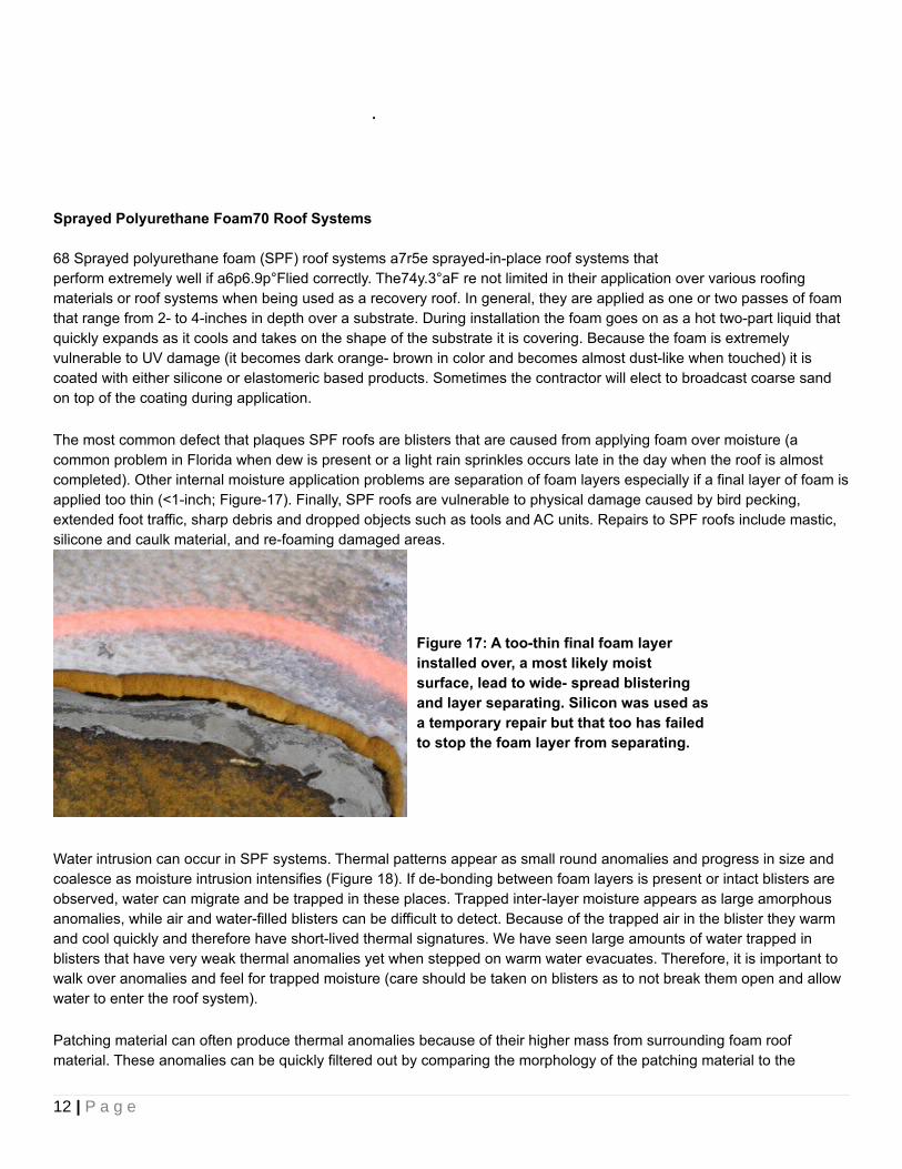
The most common defect that plaques SPF roofs are blisters that are caused from applying foam over moisture (a common problem in Florida when dew is present or a light rain sprinkles occurs late in the day when the roof is almost completed). Other internal moisture application problems are separation of foam layers especially if a final layer of foam is applied too thin (<1-inch; Figure-17). Finally, SPF roofs are vulnerable to physical damage caused by bird pecking, extended foot traffic, sharp debris and dropped objects such as tools and AC units. Repairs to SPF roofs include mastic, silicone and caulk material, and re-foaming damaged areas.
Figure 17: A too-thin final foam layer installed over, a most likely moist surface, lead to wide- spread blistering and layer separating. Silicon was used as a temporary repair but that too has failed to stop the foam layer from separating.
Water intrusion can occur in SPF systems. Thermal patterns appear as small round anomalies and progress in size and coalesce as moisture intrusion intensifies (Figure 18). If de-bonding between foam layers is present or intact blisters are observed, water can migrate and be trapped in these places. Trapped inter-layer moisture appears as large amorphous anomalies, while air and water-filled blisters can be difficult to detect. Because of the trapped air in the blister they warm and cool quickly and therefore have short-lived thermal signatures. We have seen large amounts of water trapped in blisters that have very weak thermal anomalies yet when stepped on warm water evacuates. Therefore, it is important to walk over anomalies and feel for trapped moisture (care should be taken on blisters as to not break them open and allow water to enter the roof system).
Patching material can often produce thermal anomalies because of their higher mass from surrounding foam roof material. These anomalies can be quickly filtered out by comparing the morphology of the patching material to the
12 | P a g e

anomaly. However, patching materials can hold water around their boundaries, especially as they age and lose their bond with the foam. A light step on them will evacuate water most of the time.
Figure-18: Typical thermal pattern of trapped moisture in SPF system; round shaped anomalies that coalesce with one another.
Multiple Roof Systems (Recovery Roofs)
It is quite common for a new roof system to be installed over an old roof, commonly referred to as a recovery roof system. Most roof manufacturers, prior to installation, require a moisture survey to be performed to identify areas of trapped moisture and conduct other testing to determine the roof is structurally competent to accept a recovery roof. Preparing an existing roof for a new roof involves removal of loose material including ballast stone, dirt, debris, and other surface features that may interfere with the foundation of the new roof. Most of the time, an insulation board is attached to the existing roof to provide separation between the two roofs and create a smooth workable foundation for the new roof. However, if the existing roof is already smooth, only a base sheet or other thin non-absorbent roof material may be installed.
Thermal patterns associated with recovery roof systems vary from classic thermal patterns associated with wet insulation of the new roof, to very chaotic thermal patterns created by trapped moisture between the two roof systems that lack an absorbent separation layer (Figure-19). These anomalies are very difficult to resolve and pinpoint the exact location of trapped moisture.
Finally, old trapped moisture in the lower roof system can sometimes be detected with a thermal imager. Depending upon the original insulation material, anomalies may appear as faint or shadowy signatures. When trapped moisture occurs in the lower and upper roof systems, the lower trapped moisture usually produces a weak thermal signature that contrasts with a stronger signature of the top roof moisture (Figure-20).
Figure 19: Thermal pattern of inter-ply moisture trapped between two roof systems with no separating insulation layer.
13 | P a g e

Figure 20: Strong and weak thermal anomalies on a roof surface. The large anomaly in the background shows two strong anomalies (upper roof moisture) superimposed over a broader and weaker one (lower roof moisture).
ConclusionInfrared is an excellent tool to detect trapped moisture in roof systems. While it is not always necessary to use a short/mid-wave thermal imager, doing so will provide more consistent results when scanning reflective roof surfaces. Both standard and wide- angle lenses are very useful to provide a good balance between providing details of anomalies and roof features and allowing anomalies to be framed un-cropped.
It is extremely important to know the construction of the roof system you are working on prior to committing your services to scan a roof. This will provide a pre-inspection understanding of anticipated anomalies you may find and any technical limitations you may encounter. Also important to know is how each layer in the roof system affects thermal patterns. Surface materials contribute emissivity factors and mass to the roof construction, which in turn dictates the ability to resolve thermal patterns on the roof and can possible produce anomalies in areas of over-thickened roofing material. Insulation will control the shapes of anomalies you see. Deck systems can superimpose anomalies on the roof that may be mistaken for trapped moisture.
14 | P a g e