flashsystem 900 product guide
TRANSCRIPT
FlashSystem 900 Product Guide 1
��� ®
FlashSystem 900 Product GuideIBM Redbooks Product Guide
Today's global organizations depend upon the ability to unlock business insights from massive volumes of data. Now, with IBM FlashSystem 900, they can make faster decisions based on real-time insights and unleash the power of the most demanding applications, including online transaction processing (OLTP) and analytics databases, virtual desktop infrastructures (VDIs), technical computing applications, and cloud environments.
Easy to deploy and manage, the IBM FlashSystem 900 is designed to accelerate the applications that drive business. Powered by IBM FlashCore™ Technology, IBM FlashSystem provides the following characteristics:
Extreme performance with IBM MicroLatency™ delivers 90 µs write latency and 155 µs read latency
Macro efficiency lowers operating costs and increases efficiency of IT infrastructure by using much less power and space than traditional hard disk drive (HDD) and solid-state disk (SSD) solutions
Enterprise reliability protects critical assists with two-dimensional RAID protection, IBM Variable Stripe RAID, redundant and hot-swappable components, and concurrent code loads
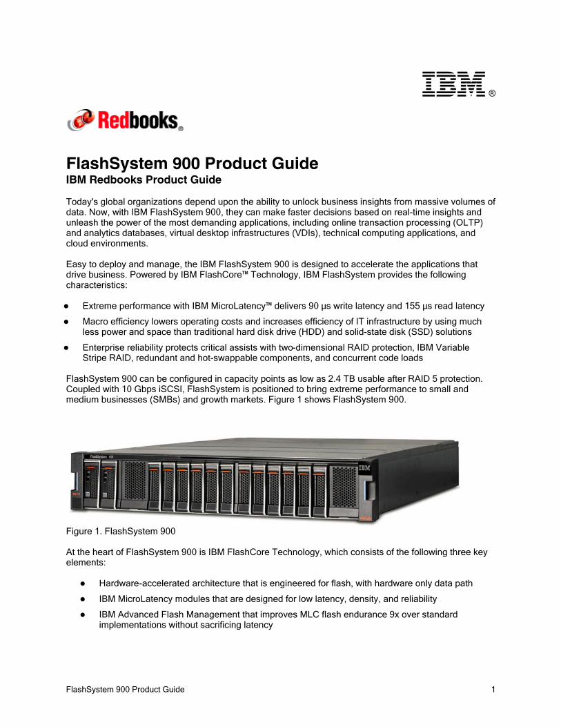
FlashSystem 900 can be configured in capacity points as low as 2.4 TB usable after RAID 5 protection. Coupled with 10 Gbps iSCSI, FlashSystem is positioned to bring extreme performance to small and medium businesses (SMBs) and growth markets. Figure 1 shows FlashSystem 900.
Figure 1. FlashSystem 900
At the heart of FlashSystem 900 is IBM FlashCore Technology, which consists of the following three key elements:
Hardware-accelerated architecture that is engineered for flash, with hardware only data path
IBM MicroLatency modules that are designed for low latency, density, and reliability
IBM Advanced Flash Management that improves MLC flash endurance 9x over standard implementations without sacrificing latency

FlashSystem 900 Product Guide 2
Figure 2 shows IBM FlashCore Technology
Figure 2. IBM FlashCore Technology
Did you know?
FlashSystem 900 has these characteristics:
FlashSystem 900 is configurable with 2.4 - 57 TB of usable capacity for scalability and flexibility.
FlashSystem 900 provides flexible interface types including Fibre Channel, Fibre Channel over Ethernet (FCoE), iSCSI, and InfiniBand to easily integrate into existing SAN environments.
FlashSystem 900 offers hardware-based AES 256 data-at-rest encryption with no performance impact.

FlashSystem 900 Product Guide 3
Key features
FlashSystem 900 provides extreme performance with IBM MicroLatency™, macro efficiency, and enterprise reliability.
Scalability and performance
FlashSystem 900 has the following scalability and performance features:
IBM FlashCore technology for consistently high performance at lower cost90us/155us read/write latency Up to 1.1 million random read 4 K IOPS Up to 10 GB/second read bandwidth
IBM-enhanced Micron MLC technology for higher storage density and improved enduranceFlexible interface types of Fibre Channel, Fibre Channel over Ethernet (FCoE), iSCSI, and InfiniBand
Up to 16 ports of 8 Gbps or eight ports of 16 Gbps Fibre ChannelUp to 16 ports of 10 Gbps FCoEUp to 16 ports of 10 Gbps iSCSIUp to eight ports of 40 Gbps quad data rate (QDR) InfiniBand
Slots for up to 12 hot-swappable IBM MicroLatency storage modules (1.2 TB, 2.9 TB, or 5.7 TB)Configurable 2.4 - 57 TB of capacity for increased flexibility
Enterprise-class reliability features
FlashSystem 900 delivers the following enterprise-class reliability features:
Concurrent code load enables customer applications to remain online during firmware upgrades to all components, including the IBM MicroLatency modules.
Hot-swappable IBM MicroLatency modules by way of tool-less front panel access. If a MicroLatency module failure occurs, critical customer applications can remain online while the defective module is replaced.
All active components are redundant and hot-swappable, including IBM MicroLatency modules, RAID controllers, management modules, interface, batteries, fans, and power supplies.
All components are easily accessible through the front or rear of the enclosure, so IBM FlashSystem 900 does not need to be moved in the rack and no top access panels or cables need to be extended.
Two-dimensional (2D) Flash RAID, which consists of IBM Variable Stripe RAID and system-wide RAID 5. Variable Stripe RAID technology helps reduce downtime and maintain performance and capacity in the event of partial or full flash chip failures. System-wide RAID 5, with easily accessed hot swappable flash modules, helps prevent data loss and promote availability.
IBM Advanced Flash Management improves flash endurance 9x over standard implementations with IBM engineered ECC, advanced wear leveling, and proprietary garbage collection, relocation, and block picking algorithms.
Energy and space efficiency
FlashSystem 900 has the following energy and space efficiency characteristics:
40% greater density than previous generation 4x greater capacity than competitive all-flash products Reduced power, space, and cooling with only 625 watts typical operating power and 2U form factor
FlashSystem 900 Product Guide 4
Manageability and security
FlashSystem 900 offers the following manageability and security features:
Hardware-accelerated AES-XTS 256-bit data at rest encryption including Hot Encryption Activation and Hot Encryption Re-key
Intuitive graphical user interface (GUI) and command-line interface (CLI) which is available in any supported browser
Simple Network Management Protocol (SNMP)
Email alerts
Syslog redirect to send system log messages to another host
Architecture and key components
IBM FlashSystem 900 enclosures include two fully redundant canisters. Each canister contains a RAID controller, two interface cards, and a management controller with an associated 1 Gbps Ethernet port. Each canister also has a USB port and two hot-swappable fan modules.
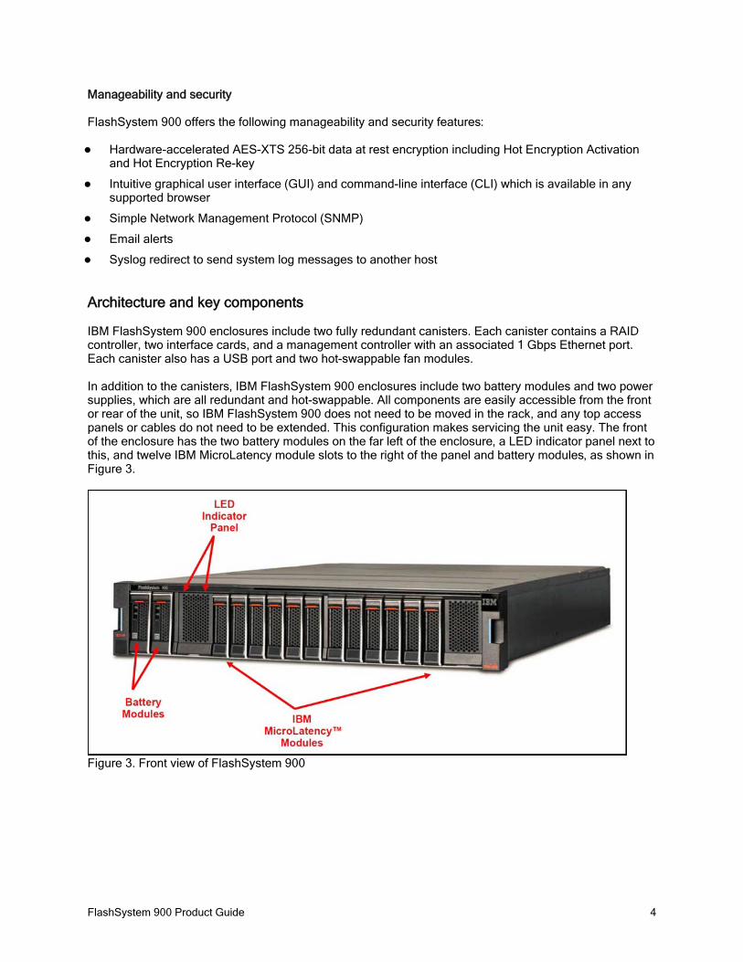
In addition to the canisters, IBM FlashSystem 900 enclosures include two battery modules and two power supplies, which are all redundant and hot-swappable. All components are easily accessible from the front or rear of the unit, so IBM FlashSystem 900 does not need to be moved in the rack, and any top access panels or cables do not need to be extended. This configuration makes servicing the unit easy. The front of the enclosure has the two battery modules on the far left of the enclosure, a LED indicator panel next to this, and twelve IBM MicroLatency module slots to the right of the panel and battery modules, as shown in Figure 3.
Figure 3. Front view of FlashSystem 900

FlashSystem 900 Product Guide 5
Figure 4 shows the components of IBM FlashSystem 900 from the rear. One of the two canisters is removed, and you see two interface cards and two fan modules. The power supply unit to the right of the fans provides redundant power to the system. All components are concurrently maintainable except for the passive midplane, enclosure LED board, and power interposer board. All external connections are from the rear of the system.
Figure 4. Rear view of FlashSystem 900 with one canister removed
Figure 5 shows a rear view of FlashSystem 900 with Fibre Channel or FCoE interfaces. The canisters are to the left (large units) and the two power supply units are to the right (small units).
Figure 5. Rear view with Fibre Channel interface cards
FlashSystem 900 Product Guide 6
Specifications
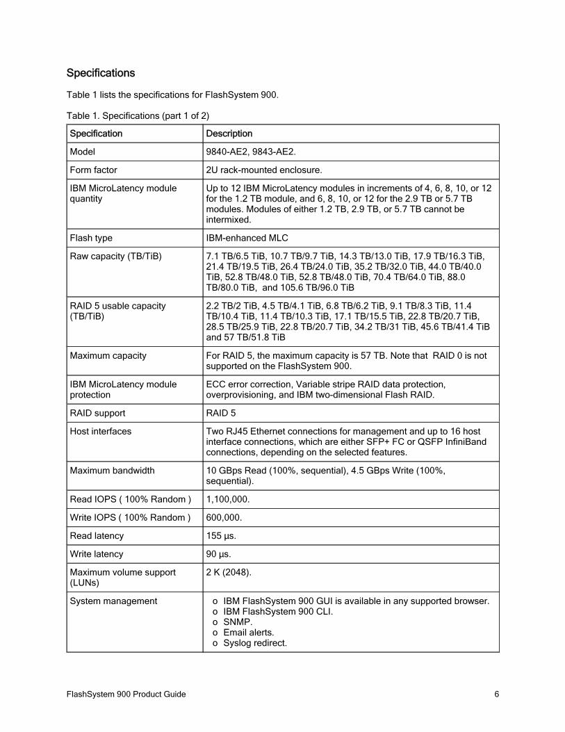
Table 1 lists the specifications for FlashSystem 900.
Table 1. Specifications (part 1 of 2)
Specification Description
Model 9840-AE2, 9843-AE2.
Form factor 2U rack-mounted enclosure.
IBM MicroLatency module quantity
Up to 12 IBM MicroLatency modules in increments of 4, 6, 8, 10, or 12 for the 1.2 TB module, and 6, 8, 10, or 12 for the 2.9 TB or 5.7 TB modules. Modules of either 1.2 TB, 2.9 TB, or 5.7 TB cannot be intermixed.
Flash type IBM-enhanced MLC
Raw capacity (TB/TiB) 7.1 TB/6.5 TiB, 10.7 TB/9.7 TiB, 14.3 TB/13.0 TiB, 17.9 TB/16.3 TiB, 21.4 TB/19.5 TiB, 26.4 TB/24.0 TiB, 35.2 TB/32.0 TiB, 44.0 TB/40.0 TiB, 52.8 TB/48.0 TiB, 52.8 TB/48.0 TiB, 70.4 TB/64.0 TiB, 88.0 TB/80.0 TiB, and 105.6 TB/96.0 TiB
RAID 5 usable capacity (TB/TiB)
2.2 TB/2 TiB, 4.5 TB/4.1 TiB, 6.8 TB/6.2 TiB, 9.1 TB/8.3 TiB, 11.4 TB/10.4 TiB, 11.4 TB/10.3 TiB, 17.1 TB/15.5 TiB, 22.8 TB/20.7 TiB, 28.5 TB/25.9 TiB, 22.8 TB/20.7 TiB, 34.2 TB/31 TiB, 45.6 TB/41.4 TiB and 57 TB/51.8 TiB
Maximum capacity For RAID 5, the maximum capacity is 57 TB. Note that RAID 0 is not supported on the FlashSystem 900.
IBM MicroLatency module protection
ECC error correction, Variable stripe RAID data protection, overprovisioning, and IBM two-dimensional Flash RAID.
RAID support RAID 5
Host interfaces Two RJ45 Ethernet connections for management and up to 16 host interface connections, which are either SFP+ FC or QSFP InfiniBand connections, depending on the selected features.
Maximum bandwidth 10 GBps Read (100%, sequential), 4.5 GBps Write (100%, sequential).
Read IOPS ( 100% Random ) 1,100,000.
Write IOPS ( 100% Random ) 600,000.
Read latency 155 µs.
Write latency 90 µs.
Maximum volume support (LUNs)
2 K (2048).
System management IBM FlashSystem 900 GUI is available in any supported browser.oIBM FlashSystem 900 CLI.oSNMP.oEmail alerts.oSyslog redirect.o
FlashSystem 900 Product Guide 7
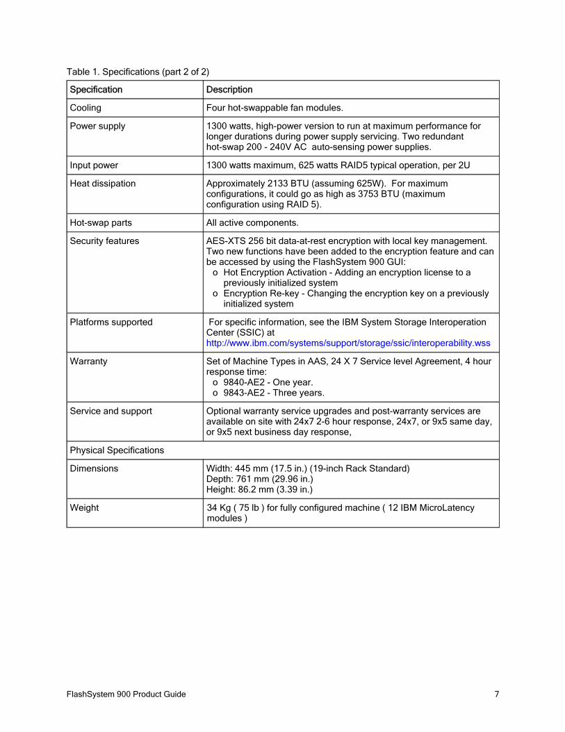
Table 1. Specifications (part 2 of 2)
Specification Description
Cooling Four hot-swappable fan modules.
Power supply 1300 watts, high-power version to run at maximum performance for longer durations during power supply servicing. Two redundant hot-swap 200 - 240V AC auto-sensing power supplies.
Input power 1300 watts maximum, 625 watts RAID5 typical operation, per 2U
Heat dissipation Approximately 2133 BTU (assuming 625W). For maximum configurations, it could go as high as 3753 BTU (maximum configuration using RAID 5).
Hot-swap parts All active components.
Security features AES-XTS 256 bit data-at-rest encryption with local key management. Two new functions have been added to the encryption feature and can be accessed by using the FlashSystem 900 GUI:
Hot Encryption Activation - Adding an encryption license to a opreviously initialized systemEncryption Re-key - Changing the encryption key on a previously oinitialized system
Platforms supported For specific information, see the IBM System Storage Interoperation Center (SSIC) at http://www.ibm.com/systems/support/storage/ssic/interoperability.wss
Warranty Set of Machine Types in AAS, 24 X 7 Service level Agreement, 4 hour response time:
9840-AE2 - One year.o9843-AE2 - Three years.o
Service and support Optional warranty service upgrades and post-warranty services are available on site with 24x7 2-6 hour response, 24x7, or 9x5 same day, or 9x5 next business day response,
Physical Specifications
Dimensions Width: 445 mm (17.5 in.) (19-inch Rack Standard)Depth: 761 mm (29.96 in.)Height: 86.2 mm (3.39 in.)
Weight 34 Kg ( 75 lb ) for fully configured machine ( 12 IBM MicroLatency modules )

FlashSystem 900 Product Guide 8
Models
The following set of Machine Types are supported in AAS as follows:
9840-AE2 - Warranty period 1 year9843-AE2 - Warranty period 3 years
All FlashSystem 900. Storage systems include the IBM MicroLatency modules and blanks, power supplies, fans, and canisters preinstalled. The IBM MicroLatency module type and quantity and the host interface I/O cards must be pre-specified. The batteries are packaged separately and must be installed by the person performing the FlashSystem 900 installation, before powering on the machine.
The following items are also shipped with FlashSystem 900:
System chassisRack rail kitWarranty documentationPrinted quick start guideSelected power cablesSelected interface cables (if any)License CD
Interface cards
IBM FlashSystem 900 supports only one interface type per system. For example, it is not possible to use two Fibre Channel interface cards and two InfiniBand interface cards in the same enclosure.
Interface cards are sold in groups of two feature codes (providing a total of four cards), and supply interfaces of either eight or 16 ports for each system.
IBM FlashSystem 900 supports the following interface protocols and number of connections:
Fibre Channel (16 ports of 8 Gbps; these ports also support 4 Gbps)Fibre Channel (eight ports of 16 Gbps; these ports also support 8 Gbps and 4 Gbps)FCoE (16 ports of 10 Gbps FCoE)Internet Small Computer System Interface (iSCSI) (16 ports of 10 Gbps iSCSI)InfiniBand (eight ports of QDR InfiniBand 40 Gbps)
FlashSystem 900 Product Guide 9
Fibre Channel support
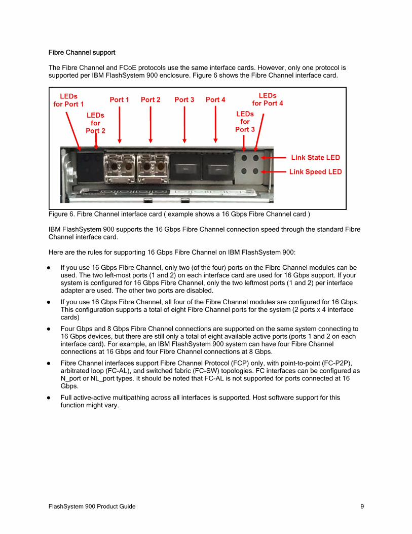
The Fibre Channel and FCoE protocols use the same interface cards. However, only one protocol is supported per IBM FlashSystem 900 enclosure. Figure 6 shows the Fibre Channel interface card.
Figure 6. Fibre Channel interface card ( example shows a 16 Gbps Fibre Channel card )
IBM FlashSystem 900 supports the 16 Gbps Fibre Channel connection speed through the standard Fibre Channel interface card.
Here are the rules for supporting 16 Gbps Fibre Channel on IBM FlashSystem 900:
If you use 16 Gbps Fibre Channel, only two (of the four) ports on the Fibre Channel modules can be used. The two left-most ports (1 and 2) on each interface card are used for 16 Gbps support. If your system is configured for 16 Gbps Fibre Channel, only the two leftmost ports (1 and 2) per interface adapter are used. The other two ports are disabled.
If you use 16 Gbps Fibre Channel, all four of the Fibre Channel modules are configured for 16 Gbps. This configuration supports a total of eight Fibre Channel ports for the system (2 ports x 4 interface cards)
Four Gbps and 8 Gbps Fibre Channel connections are supported on the same system connecting to 16 Gbps devices, but there are still only a total of eight available active ports (ports 1 and 2 on each interface card). For example, an IBM FlashSystem 900 system can have four Fibre Channel connections at 16 Gbps and four Fibre Channel connections at 8 Gbps.
Fibre Channel interfaces support Fibre Channel Protocol (FCP) only, with point-to-point (FC-P2P), arbitrated loop (FC-AL), and switched fabric (FC-SW) topologies. FC interfaces can be configured as N_port or NL_port types. It should be noted that FC-AL is not supported for ports connected at 16 Gbps.
Full active-active multipathing across all interfaces is supported. Host software support for this function might vary.
FlashSystem 900 Product Guide 10
Fibre Channel over Ethernet support
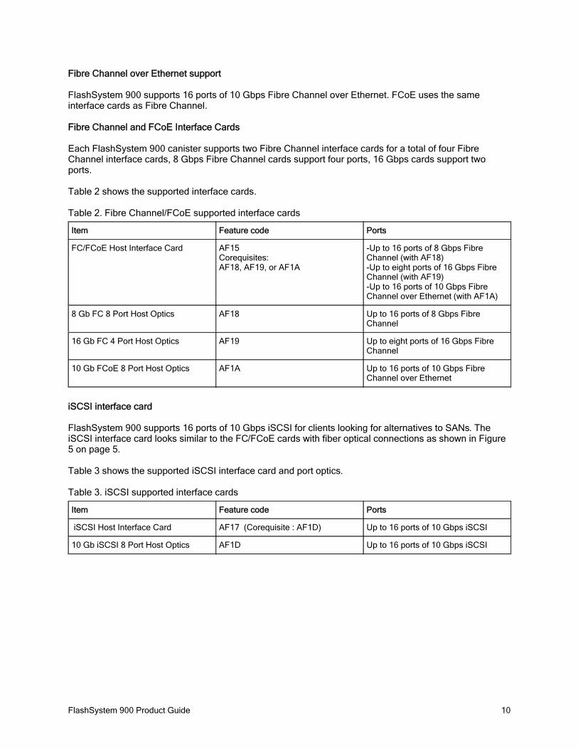
FlashSystem 900 supports 16 ports of 10 Gbps Fibre Channel over Ethernet. FCoE uses the same interface cards as Fibre Channel.
Fibre Channel and FCoE Interface Cards
Each FlashSystem 900 canister supports two Fibre Channel interface cards for a total of four Fibre Channel interface cards, 8 Gbps Fibre Channel cards support four ports, 16 Gbps cards support two ports.
Table 2 shows the supported interface cards.
Table 2. Fibre Channel/FCoE supported interface cards
Item Feature code Ports
FC/FCoE Host Interface Card AF15Corequisites:AF18, AF19, or AF1A
-Up to 16 ports of 8 Gbps Fibre Channel (with AF18)-Up to eight ports of 16 Gbps Fibre Channel (with AF19)-Up to 16 ports of 10 Gbps Fibre Channel over Ethernet (with AF1A)
8 Gb FC 8 Port Host Optics AF18 Up to 16 ports of 8 Gbps Fibre Channel
16 Gb FC 4 Port Host Optics AF19 Up to eight ports of 16 Gbps Fibre Channel
10 Gb FCoE 8 Port Host Optics AF1A Up to 16 ports of 10 Gbps Fibre Channel over Ethernet
iSCSI interface card
FlashSystem 900 supports 16 ports of 10 Gbps iSCSI for clients looking for alternatives to SANs. The iSCSI interface card looks similar to the FC/FCoE cards with fiber optical connections as shown in Figure 5 on page 5.
Table 3 shows the supported iSCSI interface card and port optics.
Table 3. iSCSI supported interface cards
Item Feature code Ports
iSCSI Host Interface Card AF17 (Corequisite : AF1D) Up to 16 ports of 10 Gbps iSCSI
10 Gb iSCSI 8 Port Host Optics AF1D Up to 16 ports of 10 Gbps iSCSI
FlashSystem 900 Product Guide 11
InfiniBand interface card
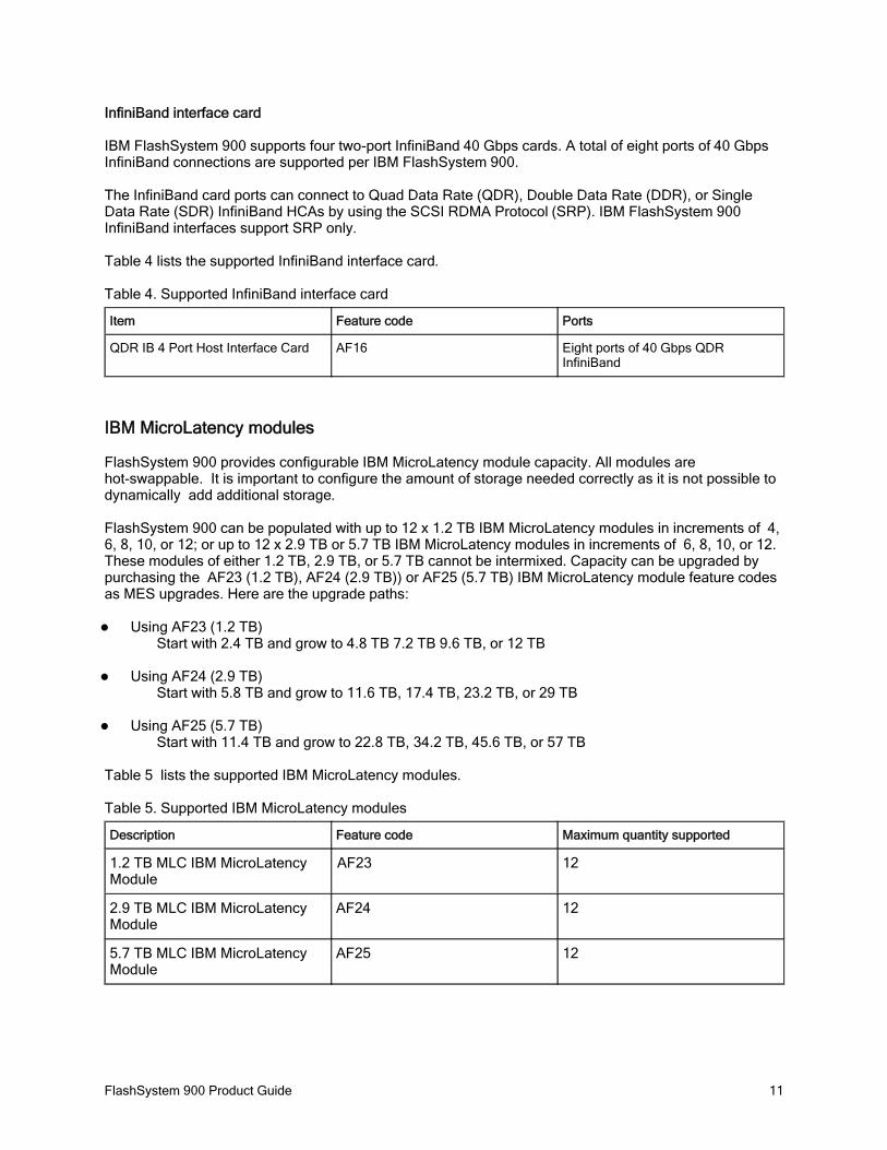
IBM FlashSystem 900 supports four two-port InfiniBand 40 Gbps cards. A total of eight ports of 40 Gbps InfiniBand connections are supported per IBM FlashSystem 900.
The InfiniBand card ports can connect to Quad Data Rate (QDR), Double Data Rate (DDR), or Single Data Rate (SDR) InfiniBand HCAs by using the SCSI RDMA Protocol (SRP). IBM FlashSystem 900 InfiniBand interfaces support SRP only.
Table 4 lists the supported InfiniBand interface card.
Table 4. Supported InfiniBand interface card
Item Feature code Ports
QDR IB 4 Port Host Interface Card AF16 Eight ports of 40 Gbps QDR InfiniBand
IBM MicroLatency modules
FlashSystem 900 provides configurable IBM MicroLatency module capacity. All modules are hot-swappable. It is important to configure the amount of storage needed correctly as it is not possible to dynamically add additional storage.
FlashSystem 900 can be populated with up to 12 x 1.2 TB IBM MicroLatency modules in increments of 4, 6, 8, 10, or 12; or up to 12 x 2.9 TB or 5.7 TB IBM MicroLatency modules in increments of 6, 8, 10, or 12. These modules of either 1.2 TB, 2.9 TB, or 5.7 TB cannot be intermixed. Capacity can be upgraded by purchasing the AF23 (1.2 TB), AF24 (2.9 TB)) or AF25 (5.7 TB) IBM MicroLatency module feature codes as MES upgrades. Here are the upgrade paths:
Using AF23 (1.2 TB)Start with 2.4 TB and grow to 4.8 TB 7.2 TB 9.6 TB, or 12 TB
Using AF24 (2.9 TB)Start with 5.8 TB and grow to 11.6 TB, 17.4 TB, 23.2 TB, or 29 TB
Using AF25 (5.7 TB)Start with 11.4 TB and grow to 22.8 TB, 34.2 TB, 45.6 TB, or 57 TB
Table 5 lists the supported IBM MicroLatency modules.
Table 5. Supported IBM MicroLatency modules
Description Feature code Maximum quantity supported
1.2 TB MLC IBM MicroLatency Module
AF23 12
2.9 TB MLC IBM MicroLatency Module
AF24 12
5.7 TB MLC IBM MicroLatency Module
AF25 12

FlashSystem 900 Product Guide 12
IBM Variable Stripe RAID
Variable Stripe RAID data protection is a unique, self-healing data protection that is managed independently by each flash controller on each IBM MicroLatency module. With Variable Stripe RAID, every flash controller creates a striped data layout across its set of chips similar to a n+1 RAID 5 array with rotating parity. When the Variable Stripe RAID algorithm detects a failure affecting one or more flash chips in a RAID stripe, the following process happens:
Data that is stored in the affected regions is reconstructed from the remaining data/parity elements in 1.the stripe.
All pages in the affected stripe, including the reconstructed data, are moved to reserved space 2.(overprovisioned area).
Subsequent requests for data in the affected stripe are directed to the new locations (now part of the 3.normal storage area in the system).
The original location of the affected stripe is added to the available overprovisioned area as a (n-1) + 4.parity stripe. (For example, if the affected stripe was a 9+1 stripe, it becomes an 8+1 stripe.).
No system-level rebuild process is necessary to maintain data protection or usable capacity after a failure caught by Variable Stripe RAID. The entire Variable Stripe RAID recovery process is automatic and transparent to the user and administrator, and typically takes place in less than a second. Variable Stripe RAID activities are not normally tracked in system logs, but the root causes of failures that are typically handled by Variable Stripe RAID-plane failures and block failures are tracked in system counters and reflected in the overall IBM MicroLatency module and system health metrics.
IBM Two-dimensional (2D) Flash RAID
The combination of IBM Variable Stripe RAID and system-level RAID 5 protection across IBM MicroLatency modules is called two-dimensional (2D) Flash RAID.
RAID 5
With RAID 5 mode, up to 2048 logical volumes (sometimes referred to as LUNs) can be created in the system, with a minimum size of 1 MB and a maximum size of the full available system capacity. Under the direction of the management module, RAID module Field Programmable Gate Arrays (FPGAs) can coordinate data transfer between modules, for example, to rebuild the system-level RAID 5 data layout.
Note: FlashSystem 900 does not support a RAID 0 configuration

FlashSystem 900 Product Guide 13
Scalable configurations
FlashSystem 900 can scale usable capacity from as low as 2.4 TB to as high as 57 TB in its compact 2U enclosure. With FlashSystem 900, many granular capacity points are possible due to the three choices in IBM MicroLatency module capacity: 1.2 TB, 2.9 TB, and 5.7 TB. IBM MicroLatency modules can be added so that IT personnel can expand capacity to support changing needs for organizations and enterprises of all sizes. However, capacity expansion does require reformat of existing RAID 5 arrays to include the new IBM MicroLatency modules.
FlashSystem 900 supports the RAID 5 configurations with the latest capacity points as listed in Table 7.
Table 7. Supported FlashSystem RAID 5 configurations with latest FlashSystem 900 capacity points
Capacity Selection (in TB) FlashSystem 900 IBM MicroLatency Modules
2.2 4 X 1.2 TB
4.5 6 X 1.2 TB
6.8 8 X 1.2 TB
9.1 10 X 1.2 TB
11.4 12 X 1.2 TB
11.4 6 X 2.9 TB
17.1 8 X 2.9 TB
22.8 10 X 2.9 TB
28.5 12 X 2.9 TB
22.8 6 X 5.7 TB
34.2 8 X 5.7 TB
45.6 10 X 5.7 TB
57 12 X 5.7 TB
RAID 5 configurations provide a high degree of redundancy with Variable Stripe RAID and RAID 5 protection.
RAID 5 data protection includes one IBM MicroLatency module dedicated as parity and another as a dedicated hot spare. Maximum capacity utilization for RAID 5 is provided using 12 IBM MicroLatency modules.
Depending on your needs, and if capacity expansion is expected over time, consider initial RAID 5 configurations with 12 IBM MicroLatency modules which provides the least capacity penalty for RAID 5 protection.
Note: Different IBM MicroLatency module sizes cannot be intermixed in the same IBM FlashSystem 900 chassis.
FlashSystem 900 Product Guide 14
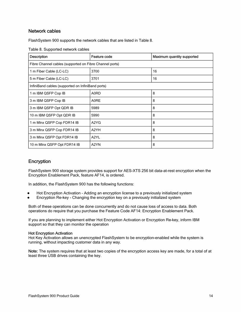
Network cables
FlashSystem 900 supports the network cables that are listed in Table 8.
Table 8. Supported network cables
Description Feature code Maximum quantity supported
Fibre Channel cables (supported on Fibre Channel ports)
1 m Fiber Cable (LC-LC) 3700 16
5 m Fiber Cable (LC-LC) 3701 16
InfiniBand cables (supported on InfiniBand ports)
1 m IBM QSFP Cop IB A0RD 8
3 m IBM QSFP Cop IB A0RE 8
3 m IBM QSFP Opt QDR IB 5989 8
10 m IBM QSFP Opt QDR IB 5990 8
1 m Mlnx QSFP Cop FDR14 IB A2YG 8
3 m Mlnx QSFP Cop FDR14 IB A2YH 8
3 m Mlnx QSFP Opt FDR14 IB A2YL 8
10 m Mlnx QSFP Opt FDR14 IB A2YN 8
Encryption
FlashSystem 900 storage system provides support for AES-XTS 256 bit data-at-rest encryption when the Encryption Enablement Pack, feature AF14, is ordered.
In addition, the FlashSystem 900 has the following functions:
Hot Encryption Activation - Adding an encryption license to a previously initialized system Encryption Re-key - Changing the encryption key on a previously initialized system
Both of these operations can be done concurrently and do not cause loss of access to data. Both operations do require that you purchase the Feature Code AF14: Encryption Enablement Pack.
If you are planning to implement either Hot Encryption Activation or Encryption Re-key, inform IBM support so that they can monitor the operation
Hot Encryption ActivationHot Key Activation allows an unencrypted FlashSystem to be encryption-enabled while the system is running, without impacting customer data in any way.
Note: The system requires that at least two copies of the encryption access key are made, for a total of at least three USB drives containing the key.
FlashSystem 900 Product Guide 15
Encryption Rekey
Rekeying is the process of creating a new key for the system. To create new keys, encryption must be enabled on the system. However, the rekey operation works whether there are encrypted arrays or not.
Before creating a new key, ensure that the canisters are online and at least one USB port contains a USB flash drive that contains the current key. During the rekey process, new keys are generated and copied to the USB flash drives. These keys are then used instead of the current keys. The rekey operation fails if at least one USB flash drive does not contain the current key. To rekey the system, you need at least three USB flash drives to store the copied key material.
For more information see the FlashSystem 900 Knowledge Center at:
https://ibm.biz/fs_900_kc
Note: The FlashSystem 900 Knowledge Center will be live on 20th March.
Batteries
Battery reconditioning feature that calibrates the gauge that reports the amount of charge on the batteries. On systems that have been installed for 10 months or more, or systems that have experienced several power outages, the recommendation to run "battery reconditioning" will appear in the Event Log shortly after upgrading.
Note: During the battery reconditioning cycle, no concurrent code upgrades can be performed. See the FlashSystem 900 Knowledge Center for more information at https://ibm.biz/fs_900_kc.
System management
The management modules in FlashSystem 900 storage system are processor complexes in the canisters. The management modules are configured for active-passive redundancy. The management modules run a highly customized Linux-based operating system that coordinates and monitors all significant functions in the system.
The management modules provide a Java based web interface, Secure Shell (SSH) access, and SNMP connectivity through external Ethernet interfaces. The web and SSH interfaces allow administrators to monitor system performance and health metrics, configure storage, and collect support data, among other features.
IBM FlashSystem 900 includes the usage of the common IBM FlashSystem 900 CLI and the IBM FlashSystem 900 GUI, which is based on the IBM XIV® GUI. IBM FlashSystem 900 supports SNMP, email forwarding (SMTP), and syslog redirection for complete enterprise management access.
The storage configuration includes defining logical units with capacities, access policies, and other parameters. No software needs to be installed on host computers to administer FlashSystem 900 beyond a web browser with Java support or a standard SSH client.

FlashSystem 900 Product Guide 16
Web interface
Navigating the management tool is simple. You can hover the cursor over one of the five function icons on the left side of the window, which highlights the function icon and shows a list of options. You can then move the cursor to the wanted option and click it. The GUI has three main sections for navigating through the management tool:
Function icons (left side)Status bars (bottom)Actions menu (upper left, or right-click the home page)
To the right of the upper middle of the GUI is the function key for managing the security of the user that is logged in. In the upper right corner is the Help button, which provides information about licenses and gives access to the FlashSystem 900 Knowledge Center.
On the far left of the window are five function icons, from top to bottom:
The Monitoring menuThe Volumes menuThe Hosts menuThe Access menuThe Settings menu

FlashSystem 900 Product Guide 17
The management GUI is the primary tool to manage the system. Figure 7 shows an overview of the management GUI and the general location of associated menu options from the front of the machine. At the bottom of the window are three status indicators. These indicators provide information about these characteristics:
Capacity usage ( lower left )Throughput in megabytes per second (MBps), IOPS, and latency in a tri-pane indicator (center) The health status of the system ( lower right )
Figure 7. IBM FlashSystem 900 Management GUI (front view of the system)
FlashSystem 900 Product Guide 18
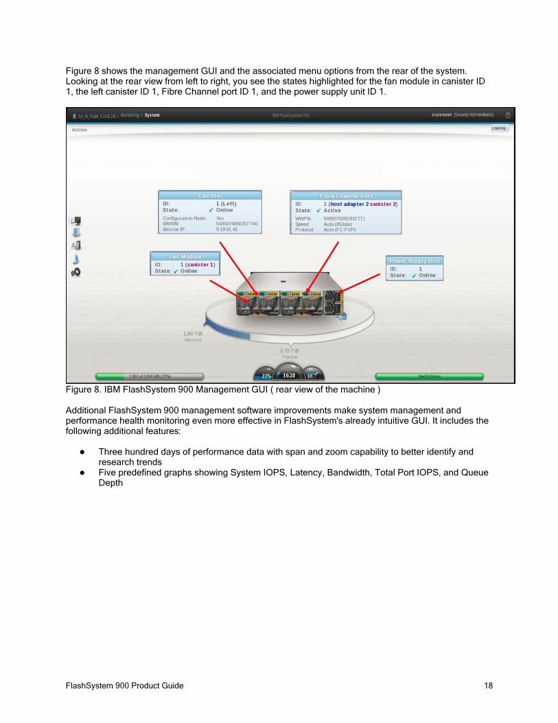
Figure 8 shows the management GUI and the associated menu options from the rear of the system. Looking at the rear view from left to right, you see the states highlighted for the fan module in canister ID 1, the left canister ID 1, Fibre Channel port ID 1, and the power supply unit ID 1.
Figure 8. IBM FlashSystem 900 Management GUI ( rear view of the machine )
Additional FlashSystem 900 management software improvements make system management and performance health monitoring even more effective in FlashSystem's already intuitive GUI. It includes the following additional features:
Three hundred days of performance data with span and zoom capability to better identify and research trendsFive predefined graphs showing System IOPS, Latency, Bandwidth, Total Port IOPS, and Queue Depth

FlashSystem 900 Product Guide 19
Performance menu overview
Enter the FlashSystem 900 performance monitor by clicking Monitoring -> Performance. The first time after the browser window is opened, system latency is displayed as shown in Figure 9.
Figure 9. Improved GUI - Performance monitoring window
The horizontal part of the graph displays the timeline. You can slide the timeline to view the past. You can also adjust the granularity of the timeline by selecting one hour, one day, one week, one month, or all. "All" displays the year to date.
Five performance charts can be reviewed from the graphs menu:
System IO:The System I/O graph displays the average number of read, write, and total I/O operations per second (IOPS) over the sample period. Each request type (read, write, and total) is represented by a different color line.
System Latency:The System Latency graph displays the average amount of time in milliseconds (ms) read and write I/O requests take over the given sampling period. Each request type (read and write) is represented by a different color line.
System Bandwidth: The System Bandwidth graph displays the average number of megabytes per second (MBps) of read, write, total, and rebuild bandwidth over the sample period. Each bandwidth type (read, write, total, and rebuild) is represented by a different color line. There is one line graph for each system that is selected.

FlashSystem 900 Product Guide 20
Interface port Total IOPS: The Total Port IOPS graph displays average number of read, write, and total IOPS over the sample period. There is one line on the graph for each port in each host adapter in each canister. Each adapter has a different color, and all four ports on an adapter have the same color.
Interface port Total Queue Depth:The Total Port Queue Depth graph displays the average number of operations of that type over the sample period. There is one line on the graph for each port in each host adapter in each canister. Each adapter has a different color, and all four ports on an adapter have the same color.
Command-line interface
The CLI provides support for the following tasks:
Managing usersConfiguring event notificationsConfiguring Call HomeConfiguring network settingsConfiguring hosts interface I/O portsConfiguring a logical unit (volume)Setting access policiesBacking up configuration settingsRestoring configuration settings
Supported platforms
IBM FlashSystem 900 supports a wide range of operating systems (Windows Server 2003 and 2008, Linux, and IBM AIX®), hardware platforms (IBM System x®, IBM Power Systems™, and x86 servers not from IBM), HBAs, and SAN fabrics. For specific information, see the IBM System Storage Interoperation Center (SSIC) at:
http://www.ibm.com/systems/support/storage/ssic/interoperability.wss

FlashSystem 900 Product Guide 21
Physical and electrical specifications
FlashSystem 900 has the following physical, electrical, and environmental specifications:
Dimensions and weightWidth: 445 mm (17.5 in.) (19-inch rack standard)oDepth: 761 mm (29.96 in.)oHeight: 86.2 mm (3.39 in.)oWeight: 17.69 kg (39 lb)o
Air temperatureOperating: Minimum of 5°C (50°F) at 30.5 m below to 3,000 m above sea level (100 ft below to o9,840 ft above); Maximum rated up to 40°C (95°F) at 30.5 m below to 950 m above sea level, de-rated 1°C for each 225 m above 950 m up to 3,000 mNon-operating: -10°C to 50°C (14°F to 125°F)o
Relative humidityOperating: 20% - 80%oNon-operating: 10% - 90%o
Electrical powerVoltage range: 100-240 V ACoFrequency: 50 - 60 Hzo
Acoustical noise emission7.2 bels (idling)o7.2 bels (operating)o
Power consumption1300 watts PSU, 900 watts maximum, 625 watts RAID5 typical operation, per 2Uo
Heat dissipation: 2133 BTU per hour (assuming 625W)
Warranty information and upgrades
IBM FlashSystem 900 is shipped with a one-year and a three-year warranty.
Technical Advisor (TA) support is provided during the warranty period. The TA enhances end-to-end support for the client’s complex IT solutions. The TA uses an integrated approach for proactive, coordinated cross-team support to allow customers to maximize IT availability. TA support for FlashSystem is delivered remotely and includes a documented support plan, coordinated problem and crisis management, reporting on the client's hardware inventories and microcode levels, and consultation about FlashSystem microcode updates. The Technical Advisor conducts a Welcome Call with the client and provides a statement of work for this support.
Flash media within IBM FlashSystem is covered in full during the warranty and maintenance period. The system is also Energy Star certified.

FlashSystem 900 Product Guide 22
IBM Global Financing
IBM Global Financing offers competitive financing to credit-qualified customers and IBM Business Partners to assist them in acquiring IT solutions. The offerings include financing for IT acquisition, including hardware, software, and services, from both IBM and other manufacturers or vendors, and commercial financing (revolving lines of credit, term loans, acquisition facilities, and inventory financing credit lines) for IBM Business Partners. Offerings (for all customer segments: small, medium, and large enterprise), rates, terms, and availability can vary by country. Contact your local IBM Global Financing organization or see the following website:http://www.ibm.com/financing
IBM Global Financing offerings are provided through IBM Credit LLC in the United States, and other IBM subsidiaries and divisions worldwide to qualified commercial and government customers. Rates are based on a customer's credit rating, financing terms, offering type, equipment type, and options, and can vary by country. Other restrictions might apply. Rates and offerings are subject to change, extension, or withdrawal without notice.
Financing solutions from IBM Global Financing can help you stretch your budget and affordably acquire the new product. But beyond the initial acquisition, the IBM end-to-end approach to IT management can also help keep your technologies current, reduce costs, minimize risk, and preserve your ability to make flexible equipment decisions throughout the entire technology lifecycle.
Related publications and links
For more information, see these resources:
IBM Redbooks Solution Guides and Product Guides for the IBM FlashSystem familyhttp://www.redbooks.ibm.com/redbooks.nsf/searchsite?SearchView&query=flashss
IBM FlashSystem family product page http://www.ibm.com/storage/flash
IBM FlashSystem 900 Knowledge Center Welcome page https://ibm.biz/fs_900_kc Note: FlashSystem 900 Knowledge Center will be live on 20th March
IBM System Storage Interoperation Center (SSIC)http://www.ibm.com/systems/support/storage/ssic/interoperability.wss
IBM Support Portal http://ibm.com/support/entry/portal/
IBM Offering Information page (announcement letters and sales manuals):http://www.ibm.com/common/ssi/index.wss?request_locale=en
On this page, enter FlashSystem, select the information type, and then click Search. On the next page, narrow your search results by geography and language
FlashSystem 900 Product Guide 23
NoticesThis information was developed for products and services offered in the U.S.A.
IBM may not offer the products, services, or features discussed in this document in other countries. Consult your local IBM representative for information on the products and services currently available in your area. Any reference to an IBM product, program, or service is not intended to state or imply that only that IBM product, program, or service may be used. Any functionally equivalent product, program, or service that does not infringe any IBM intellectual property right may be used instead. However, it is the user's responsibility to evaluate and verify the operation of any non-IBM product, program, or service. IBM may have patents or pending patent applications covering subject matter described in this document. The furnishing of this document does not give you any license to these patents. You can send license inquiries, in writing, to:
IBM Director of Licensing, IBM Corporation, North Castle Drive, Armonk, NY 10504-1785 U.S.A.
The following paragraph does not apply to the United Kingdom or any other country where such provisions are inconsistent with local law : INTERNATIONAL BUSINESS MACHINES CORPORATION PROVIDES THIS PUBLICATION "AS IS" WITHOUT WARRANTY OF ANY KIND, EITHER EXPRESS OR IMPLIED, INCLUDING, BUT NOT LIMITED TO, THE IMPLIED WARRANTIES OF NON-INFRINGEMENT, MERCHANTABILITY OR FITNESS FOR A PARTICULAR PURPOSE. Some states do not allow disclaimer of express or implied warranties in certain transactions, therefore, this statement may not apply to you. This information could include technical inaccuracies or typographical errors. Changes are periodically made to the information herein; these changes will be incorporated in new editions of the publication. IBM may make improvements and/or changes in the product(s) and/or the program(s) described in this publication at any time without notice.
Any references in this information to non-IBM Web sites are provided for convenience only and do not in any manner serve as an endorsement of those Web sites. The materials at those Web sites are not part of the materials for this IBM product and use of those Web sites is at your own risk.IBM may use or distribute any of the information you supply in any way it believes appropriate without incurring any obligation to you. Information concerning non-IBM products was obtained from the suppliers of those products, their published announcements or other publicly available sources. IBM has not tested those products and cannot confirm the accuracy of performance, compatibility or any other claims related to non-IBM products. Questions on the capabilities of non-IBM products should be addressed to the suppliers of those products. This information contains examples of data and reports used in daily business operations. To illustrate them as completely as possible, the examples include the names of individuals, companies, brands, and products. All of these names are fictitious and any similarity to the names and addresses used by an actual business enterprise is entirely coincidental.
Any performance data contained herein was determined in a controlled environment. Therefore, the results obtained in other operating environments may vary significantly. Some measurements may have been made on development-level systems and there is no guarantee that these measurements will be the same on generally available systems. Furthermore, some measurement may have been estimated through extrapolation. Actual results may vary. Users of this document should verify the applicable data for their specific environment.
COPYRIGHT LICENSE:
This information contains sample application programs in source language, which illustrate programming techniques on various operating platforms. You may copy, modify, and distribute these sample programs in any form without payment to IBM, for the purposes of developing, using, marketing or distributing application programs conforming to the application programming interface for the operating platform for which the sample programs are written. These examples have not been thoroughly tested under all conditions. IBM, therefore, cannot guarantee or imply reliability, serviceability, or function of these programs.
© Copyright International Business Machines Corporation 2015. All rights reserved.Note to U.S. Government Users Restricted Rights -- Use, duplication or disclosure restricted byGSA ADP Schedule Contract with IBM Corp.

FlashSystem 900 Product Guide 24
This document was created or updated on August 3, 2015.
Send us your comments in one of the following ways:Use the online Contact us review form found at:ibm.com/redbooksSend your comments in an e-mail to:[email protected] your comments to:IBM Corporation, International Technical Support OrganizationDept. HYTD Mail Station P0992455 South RoadPoughkeepsie, NY 12601-5400 U.S.A.
This document is available online at http://www.ibm.com/redbooks/abstracts/tips1261.html .
TrademarksIBM, the IBM logo, and ibm.com are trademarks or registered trademarks of International Business Machines Corporation in the United States, other countries, or both. These and other IBM trademarked terms are marked on their first occurrence in this information with the appropriate symbol (® or ™), indicating US registered or common law trademarks owned by IBM at the time this information was published. Such trademarks may also be registered or common law trademarks in other countries. A current list of IBM trademarks is available on the web at http://www.ibm.com/legal/copytrade.shtml.
The following terms are trademarks of the International Business Machines Corporation in the United States, other countries, or both:
IBM®Redbooks®Redbooks (logo)®
The following terms are trademarks of other companies:
Linux is a trademark of Linus Torvalds in the United States, other countries, or both.
Windows, and the Windows logo are trademarks of Microsoft Corporation in the United States, other countries, or both.
Java, and all Java-based trademarks and logos are trademarks or registered trademarks of Oracle and/or its affiliates.
Other company, product, or service names may be trademarks or service marks of others.