flasher secure user guide & reference manual
TRANSCRIPT
Flasher SecureSecured Production atContract Manufacturers
User Guide & Reference Manual
Document: UM08032Software Version: 1.12
Revision: bDate: July 2, 2021
A product of SEGGER Microcontroller GmbH
www.segger.com
2
Disclaimer
Specifications written in this document are believed to be accurate, but are not guaranteed tobe entirely free of error. The information in this manual is subject to change for functional orperformance improvements without notice. Please make sure your manual is the latest edition.While the information herein is assumed to be accurate, SEGGER Microcontroller GmbH (SEG-GER) assumes no responsibility for any errors or omissions. SEGGER makes and you receive nowarranties or conditions, express, implied, statutory or in any communication with you. SEGGERspecifically disclaims any implied warranty of merchantability or fitness for a particular purpose.
Copyright notice
You may not extract portions of this manual or modify the PDF file in any way without the priorwritten permission of SEGGER. The software described in this document is furnished under alicense and may only be used or copied in accordance with the terms of such a license.
© 2021 SEGGER Microcontroller GmbH, Monheim am Rhein / Germany
Trademarks
Names mentioned in this manual may be trademarks of their respective companies.
Brand and product names are trademarks or registered trademarks of their respective holders.
Contact address
SEGGER Microcontroller GmbH
Ecolab-Allee 5D-40789 Monheim am Rhein
Germany
Tel. +49-2173-99312-0Fax. +49-2173-99312-28E-mail: [email protected]: www.segger.com
Flasher Secure User Guide (UM08032) © 2021 SEGGER Microcontroller GmbH
3
Manual versions
This manual describes the current software version. If you find an error in the manual or aproblem in the software, please inform us and we will try to assist you as soon as possible.Contact us for further information on topics or functions that are not yet documented.
Print date: July 2, 2021
Software Revision Date By Description
1.12 210405 AW Overall improvements1.12 b 210201 AB Fixed typos1.12 a 190906 MF Minor change server hosting1.12 190603 MF Added LogLevel command line argument1.11 a 180910 MF Added further error message for better analysis1.10 b 180910 MF
1.10 a 180907 MF Corrected REST API description for manufacturer fea-tures
1.00 k 180830 MF Added REST API description for user, manufacturer anddevice features, update web interface description
1.00 h 180703 MF New feature for running as windows service1.00 g 180618 MF Bugfixes for Firmware Import and Project Create1.00 f 180614 MF Added REST API description for project features
1.00 b 180507 AB/MF Minor corrections after review
1.00 a 180504 AB/MF Added FlasherSecureServer feature
1.00 0 170401 AB Initial release.
Flasher Secure User Guide (UM08032) © 2021 SEGGER Microcontroller GmbH

4
Flasher Secure User Guide (UM08032) © 2021 SEGGER Microcontroller GmbH
5
About this document
Assumptions
This document assumes that you already have a solid knowledge of the following:• The software tools used for building your application (assembler, linker, C compiler).• The C programming language.• The target processor.• DOS command line.
If you feel that your knowledge of C is not sufficient, we recommend The C Programming Lan-guage by Kernighan and Richie (ISBN 0--13--1103628), which describes the standard in C pro-gramming and, in newer editions, also covers the ANSI C standard.
How to use this manual
This manual explains all the functions and macros that the product offers. It assumes you havea working knowledge of the C language. Knowledge of assembly programming is not required.
Typographic conventions for syntax
This manual uses the following typographic conventions:
Style Used for
Body Body text.
KeywordText that you enter at the command prompt or that appears onthe display (that is system functions, file- or pathnames).
Parameter Parameters in API functions.Sample Sample code in program examples.Sample comment Comments in program examples.
Reference Reference to chapters, sections, tables and figures or other doc-uments.
GUIElement Buttons, dialog boxes, menu names, menu commands.Emphasis Very important sections.
Flasher Secure User Guide (UM08032) © 2021 SEGGER Microcontroller GmbH

6
Flasher Secure User Guide (UM08032) © 2021 SEGGER Microcontroller GmbH
7
Table of contents
1 Introduction ..................................................................................................................10
1.1 Flasher Secure overview ............................................................................... 111.1.1 Features of Flasher Secure ................................................................. 111.1.2 Working environment .........................................................................11
1.2 Specifications ...............................................................................................131.2.1 Specifications for Flasher Secure .........................................................13
1.2.1.1 Flasher Secure download speed ............................................... 141.2.1.2 Supported Target interfaces .....................................................14
1.2.2 Specifications for Flasher Secure Server ...............................................14
2 The concept of the Flasher Secure ............................................................................ 15
2.1 Security based on emSecure ......................................................................... 162.2 Third party solutions .................................................................................... 17
2.2.1 Secure firmware installation (ST) ........................................................ 17
3 Flasher Secure Server ................................................................................................18
3.1 Installation .................................................................................................. 193.1.1 Hardware Requirements ..................................................................... 193.1.2 Connection Requirements ...................................................................193.1.3 Installation on a Linux system ............................................................ 193.1.4 Installation on a Windows system ....................................................... 193.1.5 Command line arguments .................................................................. 203.1.6 Server Certificates .............................................................................20
3.2 Projects in the Flasher Secure Server ............................................................. 213.3 Web interface .............................................................................................. 22
3.3.1 Login ............................................................................................... 223.3.2 Main page ........................................................................................ 233.3.3 Projects ........................................................................................... 24
3.3.3.1 Create a new project ..............................................................243.3.3.2 Project Edit ........................................................................... 253.3.3.3 Delete Project ........................................................................26
3.3.4 Users ...............................................................................................273.3.4.1 User Overview ....................................................................... 273.3.4.2 Adding a user account ............................................................ 283.3.4.3 Editing a user account ............................................................ 293.3.4.4 Deleting a user account .......................................................... 303.3.4.5 Activating a user account ........................................................ 313.3.4.6 Deactivating a user account .................................................... 32
3.3.5 Firmware ..........................................................................................33
Flasher Secure User Guide (UM08032) © 2021 SEGGER Microcontroller GmbH
8
3.3.5.1 Firmware Overview .................................................................333.3.5.2 Firmware upload (emSecure) ...................................................343.3.5.3 Firmware upload (ST SFI) ....................................................... 353.3.5.4 Firmware settings ...................................................................36
3.3.6 Manufacturers ...................................................................................373.3.6.1 Adding a manufacturer account ................................................383.3.6.2 Editing a manufacturer account ................................................393.3.6.3 Deleting a manufacturer account ..............................................403.3.6.4 Activating a manufacturer account ........................................... 413.3.6.5 Deactivating a manufacturer account ........................................ 423.3.6.6 Resetting a manufacturer's success rate counter ........................ 43
3.3.7 Devices ............................................................................................443.3.7.1 Devices overview ................................................................... 443.3.7.2 Device list ............................................................................. 453.3.7.3 Exporting the device list ......................................................... 46
3.3.8 Server status ....................................................................................473.3.8.1 Server Access Log ..................................................................48
3.4 REST interface .............................................................................................493.4.1 General ............................................................................................493.4.2 REST API ......................................................................................... 49
3.4.2.1 Creating a project .................................................................. 513.4.2.2 Deleting a project .................................................................. 533.4.2.3 Activating a project ................................................................ 543.4.2.4 Stopping a project ................................................................. 553.4.2.5 Finishing a project ..................................................................563.4.2.6 Moving a project to prepare state ............................................ 573.4.2.7 Importing firmware ................................................................ 583.4.2.8 Adding a user account ............................................................ 603.4.2.9 Activating a user account ........................................................ 613.4.2.10 Deactivating a user account ...................................................623.4.2.11 Deleting a user account ........................................................ 633.4.2.12 Editing a user account .......................................................... 643.4.2.13 Adding a manufacturer account ..............................................653.4.2.14 Activating a manufacturer account ..........................................663.4.2.15 Deactivating a manufacturer account ...................................... 673.4.2.16 Deleting a manufacturer account ............................................ 683.4.2.17 Editing a manufacturer account ..............................................693.4.2.18 Exporting a device list as CSV ................................................703.4.2.19 Exporting a device list as TXT ................................................ 71
3.4.3 REST API Result Codes ...................................................................... 72
4 Flasher Secure unit .................................................................................................... 80
4.1 General .......................................................................................................814.2 IP configuration ........................................................................................... 82
4.2.1 Manual IP configuration ..................................................................... 824.2.1.1 IP configuraton via J-Link Configurator ......................................824.2.1.2 IP configuration via integrated web server .................................84
4.3 Project Configuration .................................................................................... 854.3.1 Configuration files ............................................................................. 854.3.2 Accessing the configuration files ..........................................................85
4.3.2.1 Access via USB MSD mode ......................................................864.3.2.2 Access via FTP .......................................................................864.3.2.3 Access via ASCII command protocol ......................................... 86
4.4 Programming devices ................................................................................... 874.5 LED status indicators ....................................................................................884.6 Web interface .............................................................................................. 89
4.6.1 Flasher Secure main page ..................................................................894.6.2 Flasher Secure network information page .............................................904.6.3 Flasher Secure network configuration .................................................. 90
Flasher Secure User Guide (UM08032) © 2021 SEGGER Microcontroller GmbH
9
4.6.4 Flasher Secure system information page .............................................. 914.6.5 Flasher Secure emulator status page ................................................... 914.6.6 Flasher Secure About page .................................................................92
4.7 Additional Information .................................................................................. 934.7.1 Patch file support ..............................................................................934.7.2 PC-based mode .................................................................................93
5 Remote control ............................................................................................................94
5.1 Overview .....................................................................................................955.2 Handshake control ....................................................................................... 965.3 ASCII command interface ............................................................................. 97
5.3.1 Introduction ......................................................................................975.3.2 General command and reply message format ....................................... 975.3.3 General usage .................................................................................. 975.3.4 Settings for ASCII interface via RS232 .................................................975.3.5 Settings for ASCII interface via Telnet ................................................. 975.3.6 Commands and replies ...................................................................... 98
5.3.6.1 Commands to the Flasher ......................................................1005.3.6.1.1 #AUTO .....................................................................1005.3.6.1.2 #AUTO NOINFO ........................................................ 1005.3.6.1.3 #BAUDRATE<Baudrate> .............................................100
5.3.6.2 File I/O commands ............................................................... 1025.3.6.3 Replies from Flasher ............................................................. 105
6 Device Firmware ....................................................................................................... 107
6.1 emSecure Package ..................................................................................... 1086.2 Implementing emSecure ............................................................................. 109
6.2.1 Package content: .............................................................................1096.2.2 Include directories ...........................................................................109
6.3 Sample Application ..................................................................................... 1106.3.1 The main function ........................................................................... 1136.3.2 The _VerifyRSA function ...................................................................1136.3.3 The _VerifyECDSA function ............................................................... 113
7 Hardware and Adapters ............................................................................................114
7.1 ARM 20-pin JTAG/SWD Connector ................................................................ 1157.1.1 Pinout JTAG .................................................................................... 1157.1.2 Pinout SWD .................................................................................... 1167.1.3 Target power supply ........................................................................ 117
7.2 Flasher RX 14-pin connector ........................................................................1187.2.1 Target power supply ........................................................................ 119
7.3 Flasher PPC 14-pin connector ...................................................................... 1207.4 Target board design ....................................................................................121
7.4.1 Pull-up/pull-down resistors ............................................................... 1217.4.2 RESET, nTRST ................................................................................. 121
7.5 Adapters ................................................................................................... 1227.5.1 JTAG Isolator .................................................................................. 122
7.5.1.1 Pinout ................................................................................. 1227.5.2 J-Link Needle Adapter ......................................................................123
7.6 How to determine the hardware version ........................................................124
8 Support ......................................................................................................................125
8.1 Contacting support ..................................................................................... 126
9 Glossary .................................................................................................................... 127
10 Literature and references ........................................................................................130
Flasher Secure User Guide (UM08032) © 2021 SEGGER Microcontroller GmbH
Chapter 1 Introduction
This chapter provides a short overview about the Flasher Secure.
Flasher Secure User Guide (UM08032) © 2021 SEGGER Microcontroller GmbH
11 CHAPTER 1 Flasher Secure overview
1.1 Flasher Secure overviewFlasher Secure is a mass production programming system, capable of protecting the ven-dor#s IP regardless of the production site. It provides full control over the programmingprocess at contract manufacturers (CM) and similar environments.• Authenticated production with full visibility• Production volume control• CM administration and setup portal (Flasher Secure Server)• Ultra fast programming• Supports Cortex-M, RX, PPC• Prevents production of counterfeit units• No overhead in programming time• Secures production at contract manufacturers
In stand-alone mode, Flasher Secure can be operated via the start/stop button. FlasherSecure connects to a PC or a network using the USB/Ethernet/RS232 interface. It can becontrolled by handshake control or by ASCII command protocol. Using the USB connec-tion requires the J-Flash tool (for further details, please refer to the J-Flash manual onpage 130.
Flasher Secure has a 20-pin connector. Many adapters are available. See chapter Hardwareand Adapters on page 114.
1.1.1 Features of Flasher Secure• Three boot modes: PC-based mode, stand-alone mode, MSD mode• Stand-alone programmer (Once set up, Flasher Secure can be controlled without the
use of a PC program)• No power supply required, powered through USB• Supports internal and external flash devices• Approximately 100 MB memory available for target program storage
Flashermodel
Supported coresSupported
targetinterfaces
Flash programming speed(depending on target hardware)
Flasher Se-cure Cortex-M/RX/PPC JTAG, SWD between 170 and 300
Kbytes/second
1.1.2 Working environment
General
The Flasher can operate from a PC with an appropriate software like J-Flash or in stand-alone mode.
Host System
IBM PC/AT or compatible CPU: 486 (or better) with at least 128MB of RAM, running MicrosoftWindows 7, Windows 8, Windows 10. It needs to have a USB, Ethernet or RS232 interfaceavailable for communication with Flasher.
Power supply
Flasher Secure: 5V DC, min. 100 mA via USB connector.
Host System for the Flasher Secure Server• IBM PC/AT or compatible CPU: 486 (or better) running at 1GHz or faster• At least 8 GB of RAM• Operating System: Microsoft Windows 7, Windows 8, Windows 10 or Linux• Ethernet interface available for communication with Flasher Secure.
Flasher Secure User Guide (UM08032) © 2021 SEGGER Microcontroller GmbH
12 CHAPTER 1 Flasher Secure overview
Installing Flasher PC-software (J-Flash)
The latest version of the J-Flash software, which is part of the J-Link software and docu-mentation package, can always be downloaded from our website:segger.com/jlink-software.html For more information about using J-Flash please refer toUM08003_JFlashARM.pdf (J-Flash user guide) which is also available for download on ourwebsite.
Flasher Secure User Guide (UM08032) © 2021 SEGGER Microcontroller GmbH
13 CHAPTER 1 Specifications
1.2 Specifications
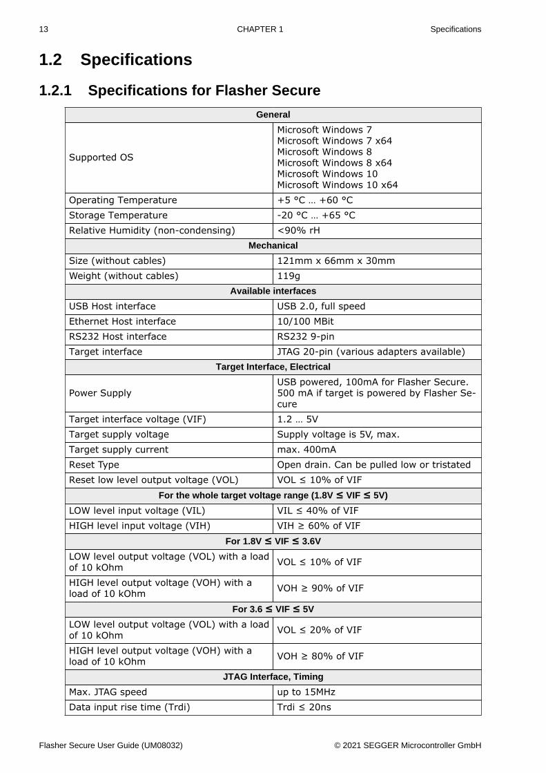
1.2.1 Specifications for Flasher Secure
General
Supported OS
Microsoft Windows 7Microsoft Windows 7 x64Microsoft Windows 8Microsoft Windows 8 x64Microsoft Windows 10Microsoft Windows 10 x64
Operating Temperature +5 °C … +60 °CStorage Temperature -20 °C … +65 °CRelative Humidity (non-condensing) <90% rH
Mechanical
Size (without cables) 121mm x 66mm x 30mmWeight (without cables) 119g
Available interfaces
USB Host interface USB 2.0, full speedEthernet Host interface 10/100 MBitRS232 Host interface RS232 9-pinTarget interface JTAG 20-pin (various adapters available)
Target Interface, Electrical
Power SupplyUSB powered, 100mA for Flasher Secure.500 mA if target is powered by Flasher Se-cure
Target interface voltage (VIF) 1.2 … 5VTarget supply voltage Supply voltage is 5V, max.Target supply current max. 400mAReset Type Open drain. Can be pulled low or tristatedReset low level output voltage (VOL) VOL ≤ 10% of VIF
For the whole target voltage range (1.8V ≤ VIF ≤ 5V)
LOW level input voltage (VIL) VIL ≤ 40% of VIFHIGH level input voltage (VIH) VIH ≥ 60% of VIF
For 1.8V ≤ VIF ≤ 3.6V
LOW level output voltage (VOL) with a loadof 10 kOhm VOL ≤ 10% of VIF
HIGH level output voltage (VOH) with aload of 10 kOhm VOH ≥ 90% of VIF
For 3.6 ≤ VIF ≤ 5V
LOW level output voltage (VOL) with a loadof 10 kOhm VOL ≤ 20% of VIF
HIGH level output voltage (VOH) with aload of 10 kOhm VOH ≥ 80% of VIF
JTAG Interface, Timing
Max. JTAG speed up to 15MHzData input rise time (Trdi) Trdi ≤ 20ns
Flasher Secure User Guide (UM08032) © 2021 SEGGER Microcontroller GmbH
14 CHAPTER 1 Specifications
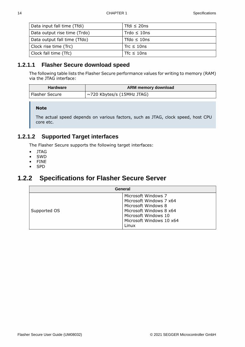
Data input fall time (Tfdi) Tfdi ≤ 20nsData output rise time (Trdo) Trdo ≤ 10nsData output fall time (Tfdo) Tfdo ≤ 10nsClock rise time (Trc) Trc ≤ 10nsClock fall time (Tfc) Tfc ≤ 10ns
1.2.1.1 Flasher Secure download speedThe following table lists the Flasher Secure performance values for writing to memory (RAM)via the JTAG interface:
Hardware ARM memory download
Flasher Secure ~720 Kbytes/s (15MHz JTAG)
Note
The actual speed depends on various factors, such as JTAG, clock speed, host CPUcore etc.
1.2.1.2 Supported Target interfacesThe Flasher Secure supports the following target interfaces:• JTAG• SWD• FINE• SPD
1.2.2 Specifications for Flasher Secure Server
General
Supported OS
Microsoft Windows 7Microsoft Windows 7 x64Microsoft Windows 8Microsoft Windows 8 x64Microsoft Windows 10Microsoft Windows 10 x64Linux
Flasher Secure User Guide (UM08032) © 2021 SEGGER Microcontroller GmbH
Chapter 2 The concept of the FlasherSecure
The Flasher Secure is a mass production tool, intended to be used at an external manu-facturing company. The goal is to protect the intellectual property against unauthorizedcopying.
It consists of a server, which runs in a trusted environment. The server should be hostedby the ip owner. The second part is a client in the form of a Flasher Secure device or a PCapplication. An IP connection via Internet between the server and the client is mandatory.
The following sub-chapters will explain the security concepts of the Flasher Secure solution.
Flasher Secure User Guide (UM08032) © 2021 SEGGER Microcontroller GmbH

16 CHAPTER 2 Security based on emSecure
2.1 Security based on emSecureMost of today’s devices provide a “unique identifier” (UID). The UID is factory programmedby the chip vendor and cannot be altered. This characteristic in combination with asym-metric cryptography based on SEGGER’s digital signature suite emSecure makes it possibleto generate a digital signature unique for each device. The digital signature can be verifiedby the firmware running on the device, so using the firmware on another device will resultin a signature failure.
The Flasher Secure server supports emSecure-RSA and emSecure-ECDSA. While emSe-cure-ECDSA requires slightly less stack RAM compared to emSecure-RSA for verificationat the same encryption strength, it significantly performs worse and requires more codespace. Therefore, we recommend using emSecure-RSA, but it may make sense to useemSecure-ECDSA, if, for example, you are already using it for other purposes.
Flasher Secure User Guide (UM08032) © 2021 SEGGER Microcontroller GmbH
17 CHAPTER 2 Third party solutions
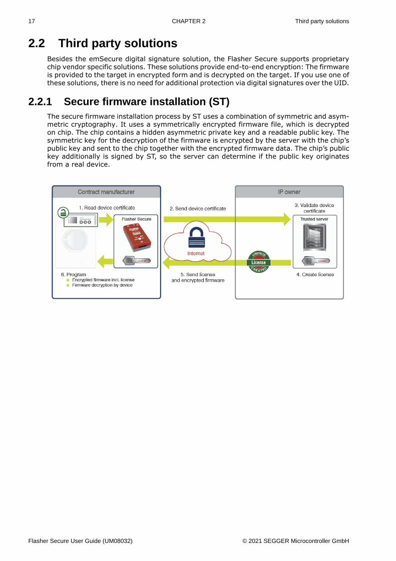
2.2 Third party solutionsBesides the emSecure digital signature solution, the Flasher Secure supports proprietarychip vendor specific solutions. These solutions provide end-to-end encryption: The firmwareis provided to the target in encrypted form and is decrypted on the target. If you use one ofthese solutions, there is no need for additional protection via digital signatures over the UID.
2.2.1 Secure firmware installation (ST)The secure firmware installation process by ST uses a combination of symmetric and asym-metric cryptography. It uses a symmetrically encrypted firmware file, which is decryptedon chip. The chip contains a hidden asymmetric private key and a readable public key. Thesymmetric key for the decryption of the firmware is encrypted by the server with the chip’spublic key and sent to the chip together with the encrypted firmware data. The chip’s publickey additionally is signed by ST, so the server can determine if the public key originatesfrom a real device.
Flasher Secure User Guide (UM08032) © 2021 SEGGER Microcontroller GmbH
Chapter 3 Flasher Secure Server
The server, as the key component, controls the manufacturing process. It authorizes eachproduced device, keeps track of the manufacturers and intervenes if they behave in anunusual manner. It also provides automatic firmware updates to the Flasher Secure clients.
The server provides an interface for the Flasher Secure clients and a web interface foradministration. Any communication over the network is secured via transport layer security(TLS).
Flasher Secure User Guide (UM08032) © 2021 SEGGER Microcontroller GmbH
19 CHAPTER 3 Installation
3.1 InstallationThe Flasher Secure Server is available for the following operation systems:• Windows• Linux
3.1.1 Hardware RequirementsThe following hardware is recommended for the Flasher Secure Server:
Hardware part Required minimum
Cores 1Core clock 1 GHzRAM 8 GB
Harddrive 32GB (mainly depends on the number ofprojects and devices)
3.1.2 Connection RequirementsThe Flasher Secure Server requires to be connectable at ports:• Port 3085 is used for the built-in web server, providing the user interface.• Port 3110 is used for the Flasher Secure unit to connect to the server.
3.1.3 Installation on a Linux systemThe Linux installation requires the following steps:• Create a user account for the FlasherSecureServer, e.g. FlashSecServ• Create a directory for your instance of the Flasher Secure Server, e.g. sudo mkdir /
opt/SEGGER/FlasherSecureServer• Change the owner of the directory, e.g. sudo chown FlashSecServUsr /opt/SEGGER/
FlasherSecureServer, the Flasher Secure Server will put all its data into subdirectoriesof this root directory.
• Copy the shipment Flasher_Secure_Linux_x64.tar.gz to the created folder• Extract the shipment in the folder, e.g. tar xvzf Flasher_Secure_Linux_x64.tar.gz• Create a startup script for your system, e.g. use the sample systemd config file to start
the server binary with the correct user account.• If you have a firewall, ensure that the FlasherSecureServer can be reached at ports
3085 and 3110 via the TCP protocol.• Reboot your system or start the FlasherSecureServer application. (note: start the
Flasher Secure Server from the installation directory and not with a fully qualified pathfrom elsewhere.)
Now everything is ready for the first use.
3.1.4 Installation on a Windows systemThe Windows installation requires the following steps:• Create a directory for your instance of the Flasher Secure Server, e.g. mkdir C:\SEGGER
\FlasherSecureServer• Copy the shipment Flasher_Secure_Windows.zip to the created folder• Extract the shipment in the folder• Create a service for your system that starts the Flasher Secure Server at start-
up, e.g. sc create “FlasherSecureServer” -binpath= “C:\FlasherSecureServer\FlasherSecureServer.exe --service -WorkingDir ”C:\FlasherSecureServer“”Please refer to your Windows documentation for further details.
• If you have a firewall, ensure that the FlasherSecureServer can be reached at the port3085 and 3110 via the TCP protocol.
Flasher Secure User Guide (UM08032) © 2021 SEGGER Microcontroller GmbH
20 CHAPTER 3 Installation
• Reboot your system or start the FlasherSecureServer application. (note: start theFlasher Secure Server from the installation directory and not with a fully qualifiedpath from elsewhere, or use the command line argument to set the working directoryproperly.)
Now everything is ready for the first use.
Note
If you want to run the Flasher Secure Server as a Windows service, you need to passthe command line argument WorkingDir to the Flasher Secure Server at start-up. SeeFlasherSecureServerCommandLineArguments on page
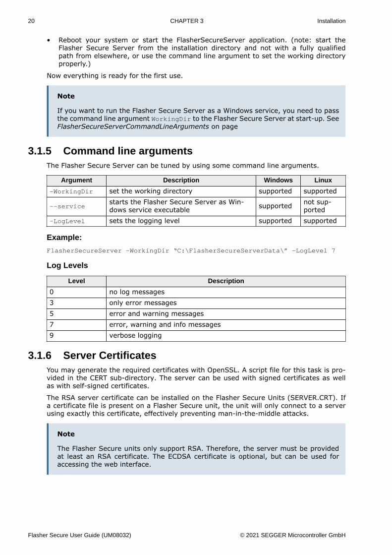
3.1.5 Command line argumentsThe Flasher Secure Server can be tuned by using some command line arguments.
Argument Description Windows Linux
-WorkingDir set the working directory supported supported
--servicestarts the Flasher Secure Server as Win-dows service executable supported not sup-
ported-LogLevel sets the logging level supported supported
Example:
FlasherSecureServer -WorkingDir “C:\FlasherSecureServerData\” -LogLevel 7
Log Levels
Level Description
0 no log messages3 only error messages5 error and warning messages7 error, warning and info messages9 verbose logging
3.1.6 Server CertificatesYou may generate the required certificates with OpenSSL. A script file for this task is pro-vided in the CERT sub-directory. The server can be used with signed certificates as wellas with self-signed certificates.
The RSA server certificate can be installed on the Flasher Secure Units (SERVER.CRT). Ifa certificate file is present on a Flasher Secure unit, the unit will only connect to a serverusing exactly this certificate, effectively preventing man-in-the-middle attacks.
Note
The Flasher Secure units only support RSA. Therefore, the server must be providedat least an RSA certificate. The ECDSA certificate is optional, but can be used foraccessing the web interface.
Flasher Secure User Guide (UM08032) © 2021 SEGGER Microcontroller GmbH
21 CHAPTER 3 Projects in the Flasher Secure Server
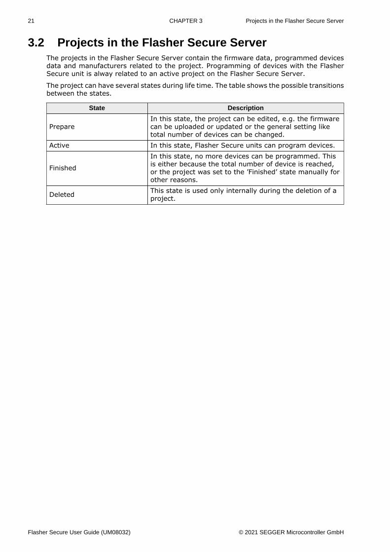
3.2 Projects in the Flasher Secure ServerThe projects in the Flasher Secure Server contain the firmware data, programmed devicesdata and manufacturers related to the project. Programming of devices with the FlasherSecure unit is alway related to an active project on the Flasher Secure Server.
The project can have several states during life time. The table shows the possible transitionsbetween the states.
State Description
PrepareIn this state, the project can be edited, e.g. the firmwarecan be uploaded or updated or the general setting liketotal number of devices can be changed.
Active In this state, Flasher Secure units can program devices.
Finished
In this state, no more devices can be programmed. Thisis either because the total number of device is reached,or the project was set to the ’Finished’ state manually forother reasons.
Deleted This state is used only internally during the deletion of aproject.
Flasher Secure User Guide (UM08032) © 2021 SEGGER Microcontroller GmbH
22 CHAPTER 3 Web interface
3.3 Web interface
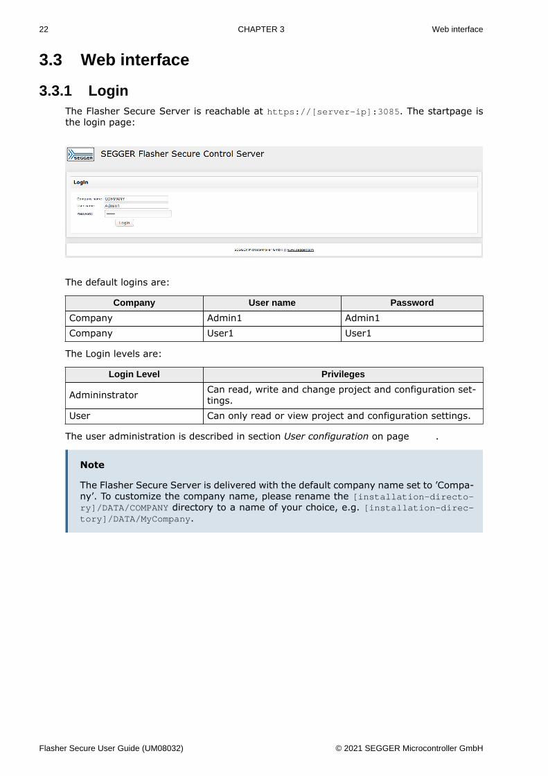
3.3.1 LoginThe Flasher Secure Server is reachable at https://[server-ip]:3085. The startpage isthe login page:
The default logins are:
Company User name Password
Company Admin1 Admin1Company User1 User1
The Login levels are:
Login Level Privileges
Admininstrator Can read, write and change project and configuration set-tings.
User Can only read or view project and configuration settings.
The user administration is described in section User configuration on page .
Note
The Flasher Secure Server is delivered with the default company name set to ’Compa-ny’. To customize the company name, please rename the [installation-directo-ry]/DATA/COMPANY directory to a name of your choice, e.g. [installation-direc-tory]/DATA/MyCompany.
Flasher Secure User Guide (UM08032) © 2021 SEGGER Microcontroller GmbH
23 CHAPTER 3 Web interface
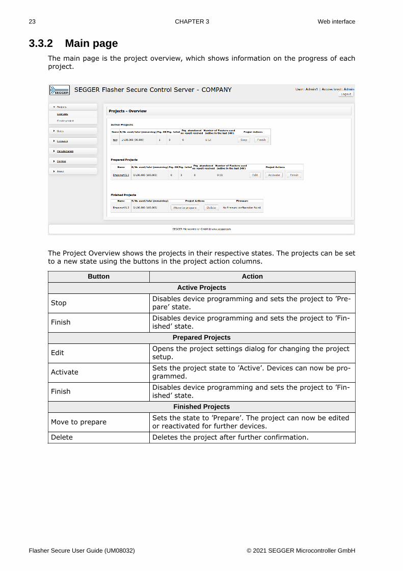
3.3.2 Main pageThe main page is the project overview, which shows information on the progress of eachproject.
The Project Overview shows the projects in their respective states. The projects can be setto a new state using the buttons in the project action columns.
Button Action
Active Projects
Stop Disables device programming and sets the project to ’Pre-pare’ state.
Finish Disables device programming and sets the project to ’Fin-ished’ state.
Prepared Projects
Edit Opens the project settings dialog for changing the projectsetup.
Activate Sets the project state to ’Active’. Devices can now be pro-grammed.
Finish Disables device programming and sets the project to ’Fin-ished’ state.
Finished Projects
Move to prepare Sets the state to ’Prepare’. The project can now be editedor reactivated for further devices.
Delete Deletes the project after further confirmation.
Flasher Secure User Guide (UM08032) © 2021 SEGGER Microcontroller GmbH
24 CHAPTER 3 Web interface
3.3.3 Projects
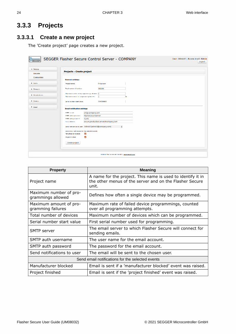
3.3.3.1 Create a new projectThe ’Create project’ page creates a new project.
Property Meaning
Project nameA name for the project. This name is used to identify it inthe other menus of the server and on the Flasher Secureunit.
Maximum number of pro-grammings allowed Defines how often a single device may be programmed.
Maximum amount of pro-gramming failures
Maximum rate of failed device programmings, countedover all programming attempts.
Total number of devices Maximum number of devices which can be programmed.Serial number start value First serial number used for programming.
SMTP server The email server to which Flasher Secure will connect forsending emails.
SMTP auth username The user name for the email account.SMTP auth password The password for the email account.Send notifications to user The email will be sent to the chosen user.
Send email notifications for the selected events
Manufacturer blocked Email is sent if a ’manufacturer blocked’ event was raised.Project finished Email is sent if the ’project finished’ event was raised.
Flasher Secure User Guide (UM08032) © 2021 SEGGER Microcontroller GmbH
25 CHAPTER 3 Web interface
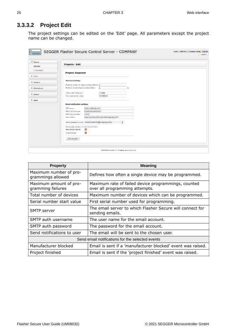
3.3.3.2 Project EditThe project settings can be edited on the ’Edit’ page. All parameters except the projectname can be changed.
Property Meaning
Maximum number of pro-grammings allowed Defines how often a single device may be programmed.
Maximum amount of pro-gramming failures
Maximum rate of failed device programmings, countedover all programming attempts.
Total number of devices Maximum number of devices which can be programmed.Serial number start value First serial number used for programming.
SMTP server The email server to which Flasher Secure will connect forsending emails.
SMTP auth username The user name for the email account.SMTP auth password The password for the email account.Send notifications to user The email will be sent to the chosen user.
Send email notifications for the selected events
Manufacturer blocked Email is sent if a ’manufacturer blocked’ event was raised.Project finished Email is sent if the ’project finished’ event was raised.
Flasher Secure User Guide (UM08032) © 2021 SEGGER Microcontroller GmbH
26 CHAPTER 3 Web interface
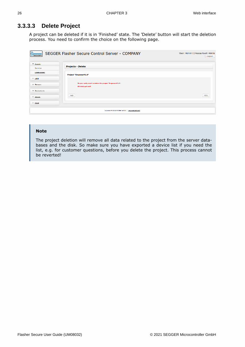
3.3.3.3 Delete ProjectA project can be deleted if it is in ’Finished’ state. The ’Delete’ button will start the deletionprocess. You need to confirm the choice on the following page.
Note
The project deletion will remove all data related to the project from the server data-bases and the disk. So make sure you have exported a device list if you need thelist, e.g. for customer questions, before you delete the project. This process cannotbe reverted!
Flasher Secure User Guide (UM08032) © 2021 SEGGER Microcontroller GmbH
27 CHAPTER 3 Web interface
3.3.4 UsersThe Flasher Secure Server includes user management and user access management. Usershave one of the following two access levels:• Administrator• User
While administrators have full access, users only have limited access. The users are notallowed to alter any settings. They have read privileges only.
The Flasher Secure Server knows two types of user accounts:• Fixed user account• Configured user account
The fixed user accounts cannot be changed during runtime of the Flasher Secure Serv-er. They are set up using the CFG_USER.TXT configuration file, located in the [installa-tion-directory]/DATA/COMPANY. These users should only be used for the initial setupprocess or evaluation.
The 2nd user type can be configured during runtime. These user accounts should be usedfor the regular operation of the Flasher Secure Server. They can have two states:• Active• Inactive
An active user account can be used to login to the Flasher Secure Server and execute theavailable actions. An inactive account cannot login and therefore cannot do anything withthe server. But its data is still available.
Note
The Flasher Secure Server is delivered with two default accounts. We recommendremoving them after creating your own accounts.
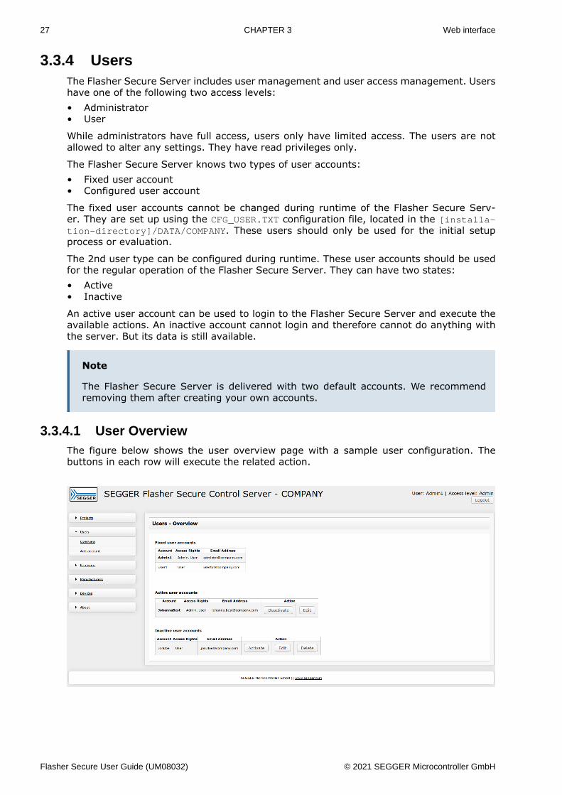
3.3.4.1 User OverviewThe figure below shows the user overview page with a sample user configuration. Thebuttons in each row will execute the related action.
Flasher Secure User Guide (UM08032) © 2021 SEGGER Microcontroller GmbH
28 CHAPTER 3 Web interface
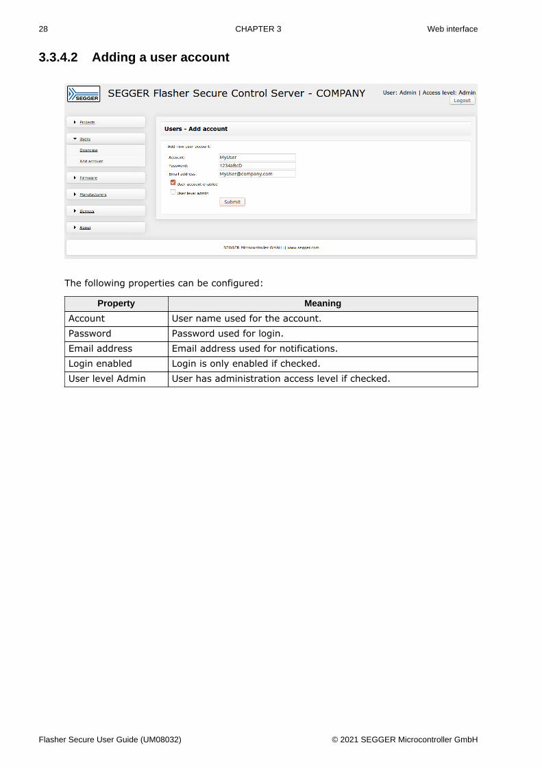
3.3.4.2 Adding a user account
The following properties can be configured:
Property Meaning
Account User name used for the account.Password Password used for login.Email address Email address used for notifications.Login enabled Login is only enabled if checked.User level Admin User has administration access level if checked.
Flasher Secure User Guide (UM08032) © 2021 SEGGER Microcontroller GmbH

29 CHAPTER 3 Web interface
3.3.4.3 Editing a user accountThe user account can be changed anytime. Select the user account by pressing the editbutton, see figure below.
On the user setting page you can change all user settings.
Flasher Secure User Guide (UM08032) © 2021 SEGGER Microcontroller GmbH
30 CHAPTER 3 Web interface
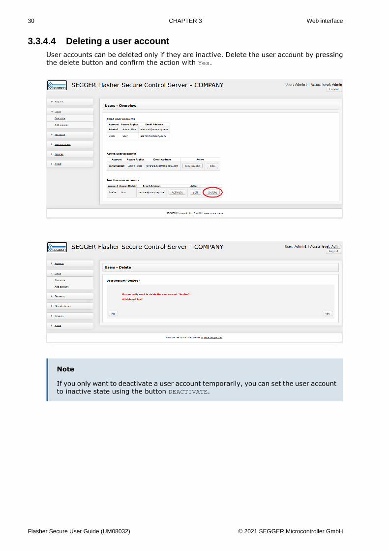
3.3.4.4 Deleting a user accountUser accounts can be deleted only if they are inactive. Delete the user account by pressingthe delete button and confirm the action with Yes.
Note
If you only want to deactivate a user account temporarily, you can set the user accountto inactive state using the button DEACTIVATE.
Flasher Secure User Guide (UM08032) © 2021 SEGGER Microcontroller GmbH
31 CHAPTER 3 Web interface
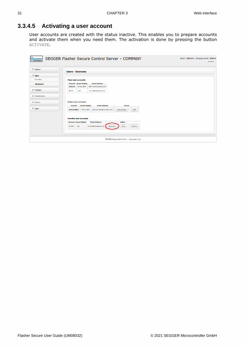
3.3.4.5 Activating a user accountUser accounts are created with the status inactive. This enables you to prepare accountsand activate them when you need them. The activation is done by pressing the buttonACTIVATE.
Flasher Secure User Guide (UM08032) © 2021 SEGGER Microcontroller GmbH

32 CHAPTER 3 Web interface
3.3.4.6 Deactivating a user accountIf you want to block a user account or disable it, you can set it to the inactive state.Therefore you need to press the button DEACTIVATE.
Flasher Secure User Guide (UM08032) © 2021 SEGGER Microcontroller GmbH

33 CHAPTER 3 Web interface
3.3.5 Firmware
3.3.5.1 Firmware OverviewThe overview page shows the currently used firmware image properties for the selectedproject.
You can switch between the projects using the drop down list and the change button.
Flasher Secure User Guide (UM08032) © 2021 SEGGER Microcontroller GmbH
34 CHAPTER 3 Web interface
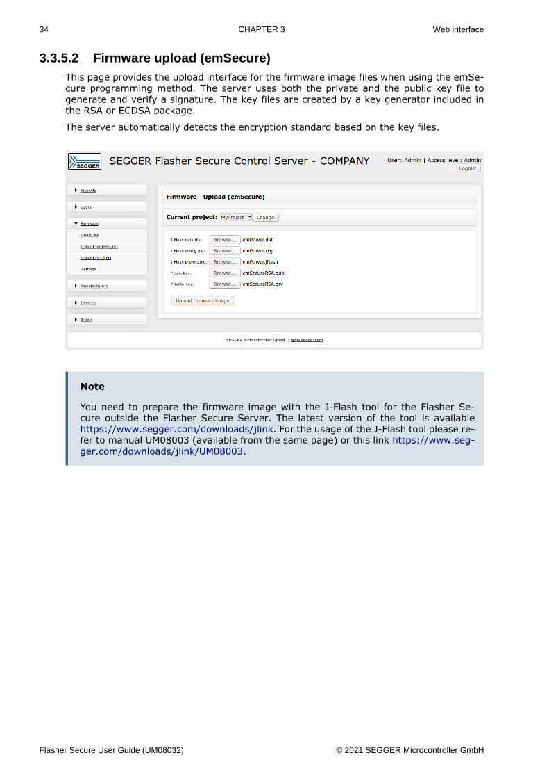
3.3.5.2 Firmware upload (emSecure)This page provides the upload interface for the firmware image files when using the emSe-cure programming method. The server uses both the private and the public key file togenerate and verify a signature. The key files are created by a key generator included inthe RSA or ECDSA package.
The server automatically detects the encryption standard based on the key files.
Note
You need to prepare the firmware image with the J-Flash tool for the Flasher Se-cure outside the Flasher Secure Server. The latest version of the tool is availablehttps://www.segger.com/downloads/jlink. For the usage of the J-Flash tool please re-fer to manual UM08003 (available from the same page) or this link https://www.seg-ger.com/downloads/jlink/UM08003.
Flasher Secure User Guide (UM08032) © 2021 SEGGER Microcontroller GmbH

35 CHAPTER 3 Web interface
3.3.5.3 Firmware upload (ST SFI)This page provides the upload interface for the firmware image files when using ST’s SFIprogramming method. Instead of a regular data file, the firmware is encapsulated in anencrypted container file (SFI file). The server additionally needs the “nonce file” and the“key file” in order to create the unique license file required to program the target device.
Note
You need to prepare the firmware image with a tool available from ST. Please contactST for more details and the toolkit for SFI flash programming.
Flasher Secure User Guide (UM08032) © 2021 SEGGER Microcontroller GmbH

36 CHAPTER 3 Web interface
3.3.5.4 Firmware settingsThe Flasher Secure needs to know at which address in the target memory the serial numberand the signature should be programmed. These addresses need to be specified on thispage. If the address 0xFFFFFFFF is specified, the corresponding data is not programmedinto the device.
Note
The firmware image file needs to contain some dummy data at the target memoryrange. Otherwise the data cannot be programmed correctly.
Flasher Secure User Guide (UM08032) © 2021 SEGGER Microcontroller GmbH
37 CHAPTER 3 Web interface
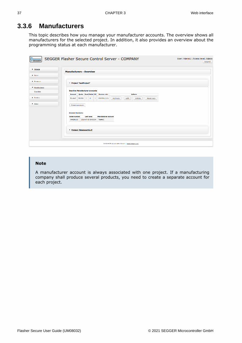
3.3.6 ManufacturersThis topic describes how you manage your manufacturer accounts. The overview shows allmanufacturers for the selected project. In addition, it also provides an overview about theprogramming status at each manufacturer.
Note
A manufacturer account is always associated with one project. If a manufacturingcompany shall produce several products, you need to create a separate account foreach project.
Flasher Secure User Guide (UM08032) © 2021 SEGGER Microcontroller GmbH

38 CHAPTER 3 Web interface
3.3.6.1 Adding a manufacturer accountThis page provides the possibility to add a manufacturer for a project. Choose the projectby using the drop down list and change button.
The following properties can be configured:
Property Meaning
Account User name used for the account or Flasher Secure authentication.Password Password used for login or Flasher Secure authentication.Number of devices Manufacturers quota on devices.
Note
A manufacturer account is always associated with one project. If a manufacturingcompany shall produce several products, you need to create a separate account foreach project.
Flasher Secure User Guide (UM08032) © 2021 SEGGER Microcontroller GmbH

39 CHAPTER 3 Web interface
3.3.6.2 Editing a manufacturer accountThis page allows to edit a manufacturer login. Choose the edit button of the manufactureryou want to edit.
The following properties can be changed:
Property Meaning
Password Password used for login or Flasher Secure authentication.Number of devices Manufacturers quota on devices.
Flasher Secure User Guide (UM08032) © 2021 SEGGER Microcontroller GmbH
40 CHAPTER 3 Web interface
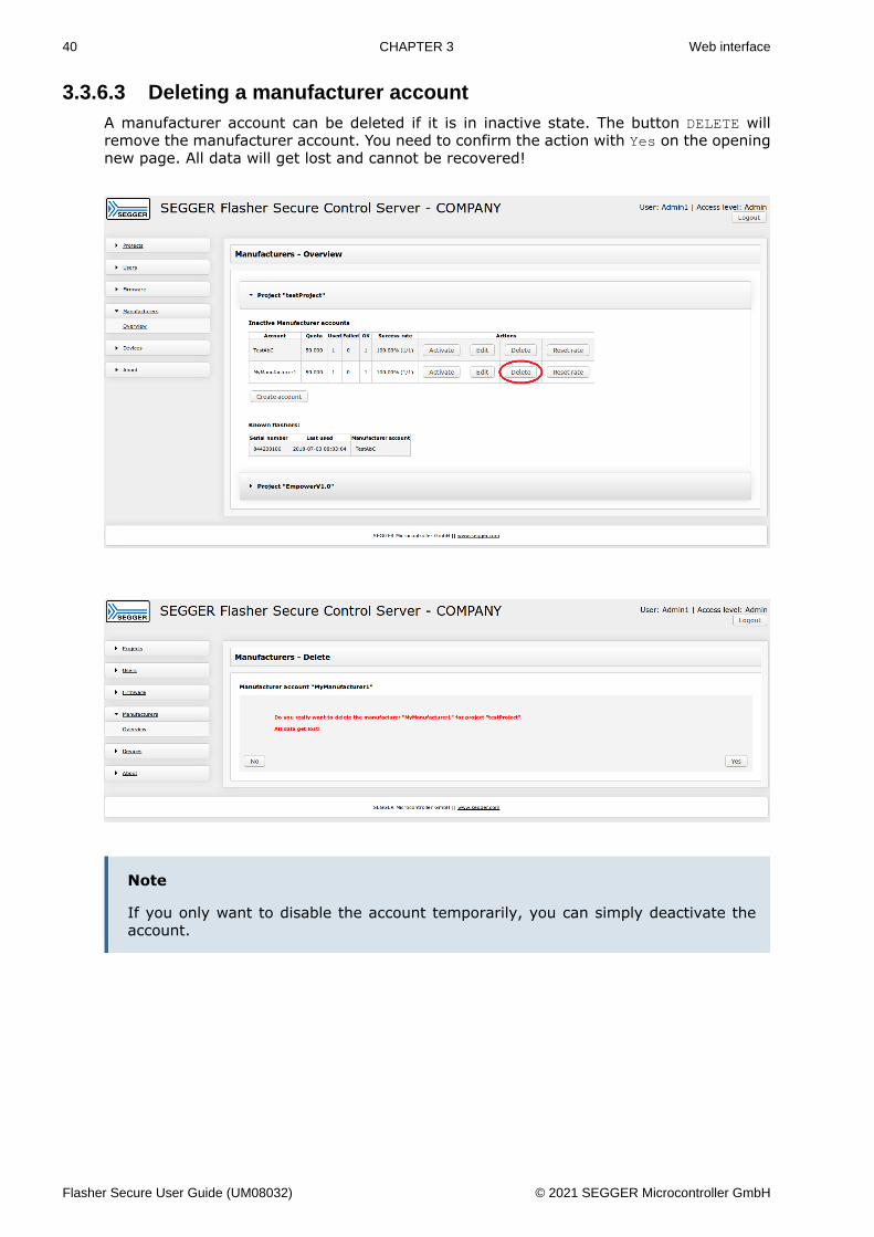
3.3.6.3 Deleting a manufacturer accountA manufacturer account can be deleted if it is in inactive state. The button DELETE willremove the manufacturer account. You need to confirm the action with Yes on the openingnew page. All data will get lost and cannot be recovered!
Note
If you only want to disable the account temporarily, you can simply deactivate theaccount.
Flasher Secure User Guide (UM08032) © 2021 SEGGER Microcontroller GmbH

41 CHAPTER 3 Web interface
3.3.6.4 Activating a manufacturer accountA manufacturer account is created with the state set to inactive. This is done with respectto the fact that you may want to set up the project configuration correctly and completelybefore allowing any manufacturer to start programming devices. Therefore you need toactivate a manufacturer account to allow production for that account. The button ACTIVATEwill set the state to active for the chosen manufacturer account.
Flasher Secure User Guide (UM08032) © 2021 SEGGER Microcontroller GmbH
42 CHAPTER 3 Web interface
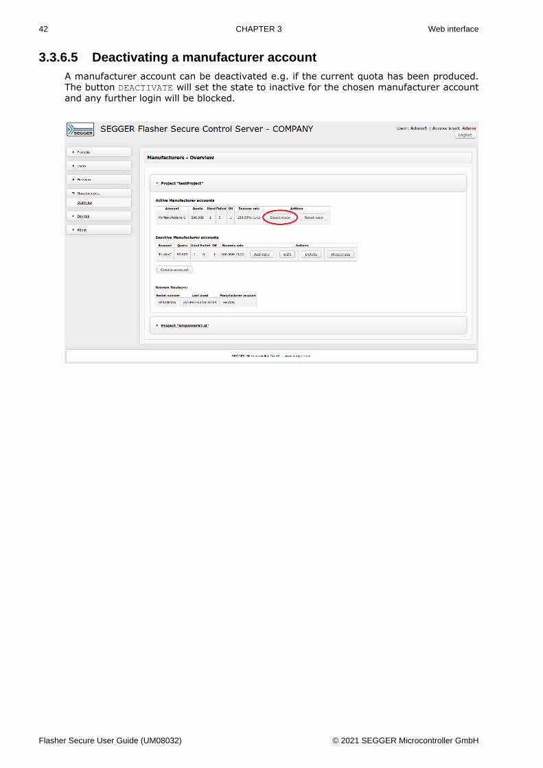
3.3.6.5 Deactivating a manufacturer accountA manufacturer account can be deactivated e.g. if the current quota has been produced.The button DEACTIVATE will set the state to inactive for the chosen manufacturer accountand any further login will be blocked.
Flasher Secure User Guide (UM08032) © 2021 SEGGER Microcontroller GmbH
43 CHAPTER 3 Web interface
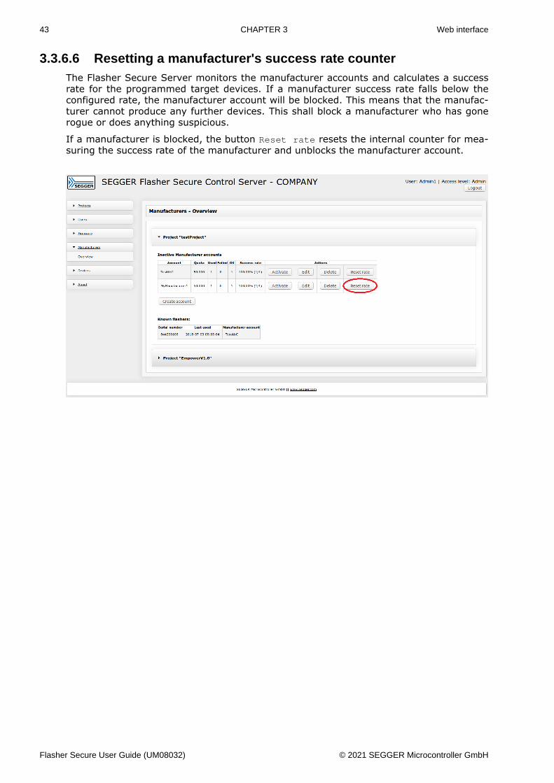
3.3.6.6 Resetting a manufacturer's success rate counterThe Flasher Secure Server monitors the manufacturer accounts and calculates a successrate for the programmed target devices. If a manufacturer success rate falls below theconfigured rate, the manufacturer account will be blocked. This means that the manufac-turer cannot produce any further devices. This shall block a manufacturer who has gonerogue or does anything suspicious.
If a manufacturer is blocked, the button Reset rate resets the internal counter for mea-suring the success rate of the manufacturer and unblocks the manufacturer account.
Flasher Secure User Guide (UM08032) © 2021 SEGGER Microcontroller GmbH
44 CHAPTER 3 Web interface
3.3.7 Devices
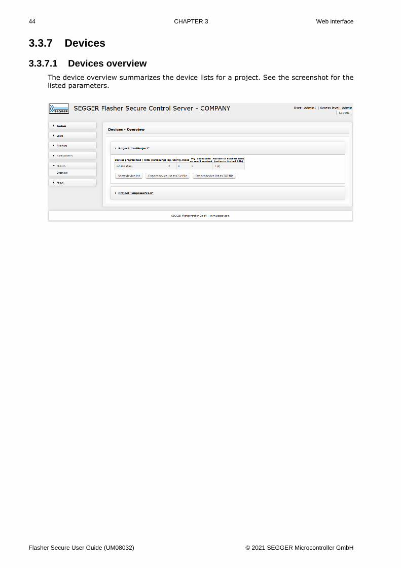
3.3.7.1 Devices overviewThe device overview summarizes the device lists for a project. See the screenshot for thelisted parameters.
Flasher Secure User Guide (UM08032) © 2021 SEGGER Microcontroller GmbH
45 CHAPTER 3 Web interface
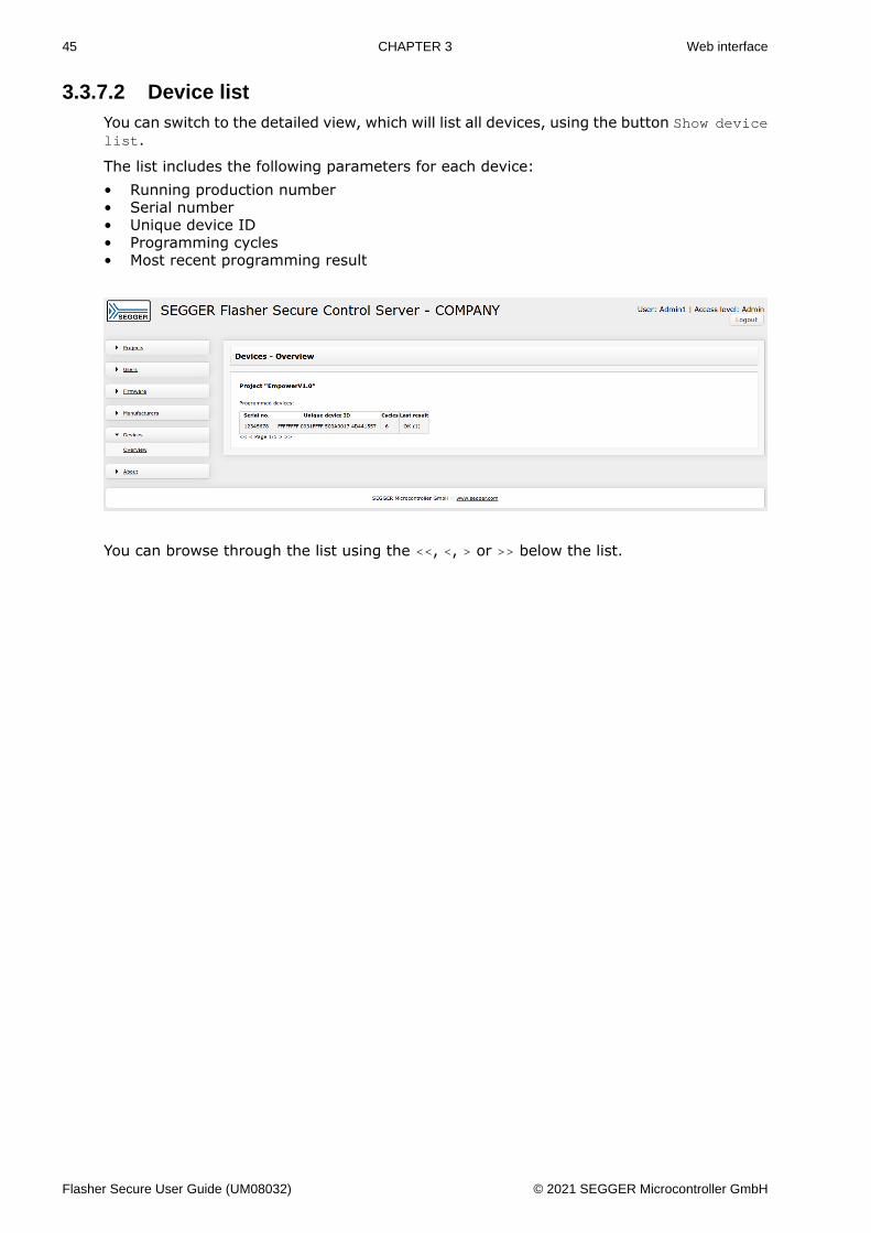
3.3.7.2 Device listYou can switch to the detailed view, which will list all devices, using the button Show devicelist.
The list includes the following parameters for each device:• Running production number• Serial number• Unique device ID• Programming cycles• Most recent programming result
You can browse through the list using the <<, <, > or >> below the list.
Flasher Secure User Guide (UM08032) © 2021 SEGGER Microcontroller GmbH
46 CHAPTER 3 Web interface
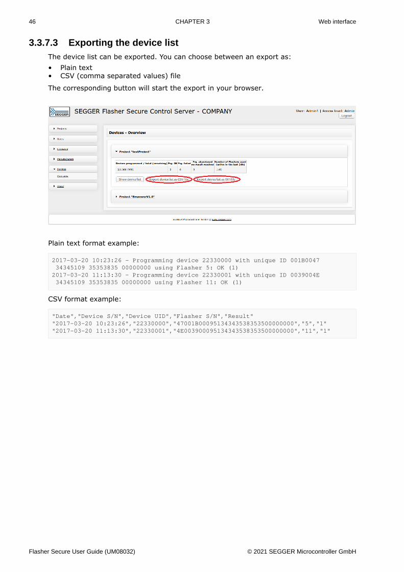
3.3.7.3 Exporting the device listThe device list can be exported. You can choose between an export as:• Plain text• CSV (comma separated values) file
The corresponding button will start the export in your browser.
Plain text format example:
2017-03-20 10:23:26 - Programming device 22330000 with unique ID 001B0047 34345109 35353835 00000000 using Flasher 5: OK (1)2017-03-20 11:13:30 - Programming device 22330001 with unique ID 0039004E 34345109 35353835 00000000 using Flasher 11: OK (1)
CSV format example:
"Date","Device S/N","Device UID","Flasher S/N","Result""2017-03-20 10:23:26","22330000","47001B00095134343538353500000000","5","1""2017-03-20 11:13:30","22330001","4E003900095134343538353500000000","11","1"
Flasher Secure User Guide (UM08032) © 2021 SEGGER Microcontroller GmbH
47 CHAPTER 3 Web interface
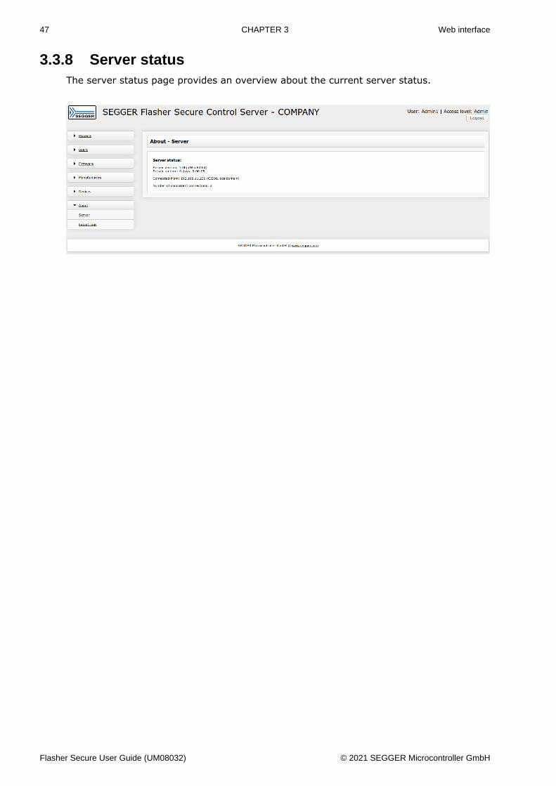
3.3.8 Server statusThe server status page provides an overview about the current server status.
Flasher Secure User Guide (UM08032) © 2021 SEGGER Microcontroller GmbH
48 CHAPTER 3 Web interface
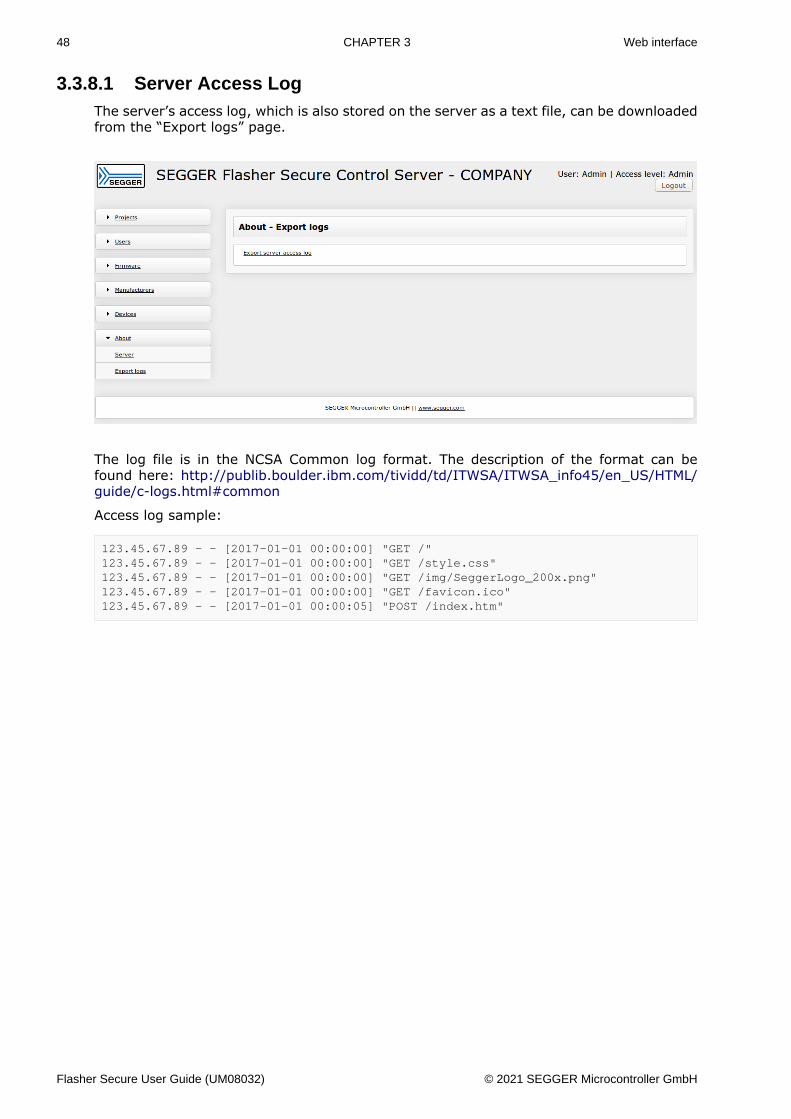
3.3.8.1 Server Access LogThe server’s access log, which is also stored on the server as a text file, can be downloadedfrom the “Export logs” page.
The log file is in the NCSA Common log format. The description of the format can befound here: http://publib.boulder.ibm.com/tividd/td/ITWSA/ITWSA_info45/en_US/HTML/guide/c-logs.html#common
Access log sample:
123.45.67.89 - - [2017-01-01 00:00:00] "GET /"123.45.67.89 - - [2017-01-01 00:00:00] "GET /style.css"123.45.67.89 - - [2017-01-01 00:00:00] "GET /img/SeggerLogo_200x.png"123.45.67.89 - - [2017-01-01 00:00:00] "GET /favicon.ico"123.45.67.89 - - [2017-01-01 00:00:05] "POST /index.htm"
Flasher Secure User Guide (UM08032) © 2021 SEGGER Microcontroller GmbH
49 CHAPTER 3 REST interface
3.4 REST interface
3.4.1 GeneralThe Flasher Secure Server can be remote-controlled using the provided REST API. Mostfunctions are accessible, but not all.
All REST API calls require parameters. The parameters are transferred in plain text format.The parameters are always name/value pairs. Each pair needs to be terminated by a car-riage return and line feed, for example:
parameter=value\r\n
The REST API calls require authentication. Therefore, you have to add the parametersCOMPANY, USERNAME and PASSWORD for the calls:
COMPANY=COMPANY\r\nUSERNAME=Admin1\r\nPASSWORD=Admin1\r\n
Note
The user account names and passwords are case sensitive!
3.4.2 REST APIThe table shows the available features.
Project features
Feature DescriptionCreate a project Creates new projectDelete a project Deletes existing projectActivate a project Sets the project state to ’active’Stop a project Sets the project state to ’prepare’Finish a project Sets the project state to ’finished’Move to prepare Sets the project state to ’prepare’
Firmware features
Feature DescriptionFirmware import Imports firmware to a project
User features
Feature DescriptionAdd user account Creates user accountActivate user ac-count Activates user account
Deactivate user ac-count Deactivates user account
Delete user account Deletes user accountEdit user account Edits user account
Device features
Feature Description
Flasher Secure User Guide (UM08032) © 2021 SEGGER Microcontroller GmbH
50 CHAPTER 3 REST interface
Export device list asCSV Exports the device list as CSV file
Export device list asTXT Exports the device list as TXT file
Manufacturer features
Feature DescriptionAdd manufactureraccount Creates manufacturer account
Activate manufac-turer account Activates manufacturer account
Deactivate manufac-turer account Deactivates manufacturer account
Delete manufactureraccount Deletes manufacturer account
Edit manufactureraccount Edits manufacturer account
Reset manufacturersuccess rate Resets manufacturer’s success rate
The REST API call will result with a response telling if the requested action was successfullyexecuted or not. The responses are in the following format:
Result=xxxx\r\nResulttext=OK. Or result text telling something went wrong.\r\n
All results with 0 or a positive number mean that the operation was successful. Negativeresults indicate an error. The result text contains further information on the error cause.
Flasher Secure User Guide (UM08032) © 2021 SEGGER Microcontroller GmbH
51 CHAPTER 3 REST interface
3.4.2.1 Creating a projectThis REST API call creates a new project.
URI:
[Server IP]:3085/REST/ProjectCreate
Parameters:
Parameter Description
COMPANY M The company name
USERNAME M The user account name; the user needs tohave administration rights
PASSWORD M The user passwordPROJECT M The name of the project to be created
TOTAL_NUMBER_DEVICES M The maximum number of devices that canbe programmed
REPROGRAMMING M The attempts of programming tries for onedevice
FAILURE_RATE M The maximum failure rate in percent for amanufacturer
START_SERIALNUMBER O The serial number for the first device
SMTP_SERVER O The SMTP server used for email notifica-tions
SMTP_AUTH_USERNAME O The SMTP authentication user nameSMTP_AUTH_PASSWORD O The SMTP authentication password
SMTP_FROM_EMAIL_ADDRESS O The email address from which the notifica-tions are sent
NOTIFICATION_TO_USERNAME O The user account which shall receive theemail notifications
NOTIFY_MANUFACTURER_BLOCKED O Send a notifications if a manufacturer isblocked; set = 1 if yes, set = 0 if no
NOTIFY_PROJECT_FINISHED O Send a notifications if a project is finished;set = 1 if yes, set = 0 if no
M: mandatory parameter, O: optional parameter
Flasher Secure User Guide (UM08032) © 2021 SEGGER Microcontroller GmbH
52 CHAPTER 3 REST interface
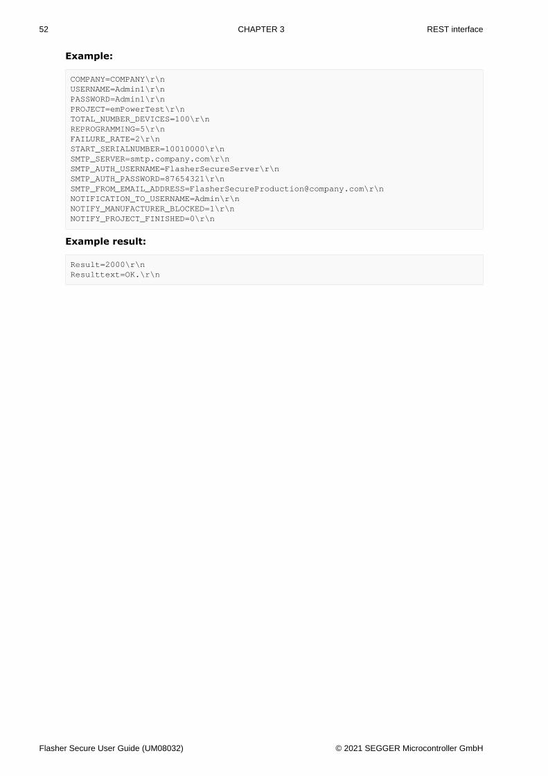
Example:
COMPANY=COMPANY\r\nUSERNAME=Admin1\r\nPASSWORD=Admin1\r\nPROJECT=emPowerTest\r\nTOTAL_NUMBER_DEVICES=100\r\nREPROGRAMMING=5\r\nFAILURE_RATE=2\r\nSTART_SERIALNUMBER=10010000\r\nSMTP_SERVER=smtp.company.com\r\nSMTP_AUTH_USERNAME=FlasherSecureServer\r\nSMTP_AUTH_PASSWORD=87654321\r\[email protected]\r\nNOTIFICATION_TO_USERNAME=Admin\r\nNOTIFY_MANUFACTURER_BLOCKED=1\r\nNOTIFY_PROJECT_FINISHED=0\r\n
Example result:
Result=2000\r\nResulttext=OK.\r\n
Flasher Secure User Guide (UM08032) © 2021 SEGGER Microcontroller GmbH
53 CHAPTER 3 REST interface
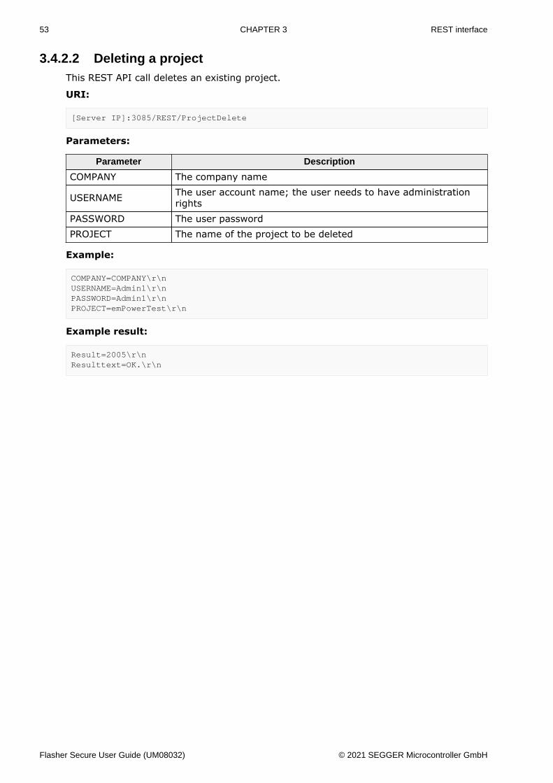
3.4.2.2 Deleting a projectThis REST API call deletes an existing project.
URI:
[Server IP]:3085/REST/ProjectDelete
Parameters:
Parameter Description
COMPANY The company name
USERNAME The user account name; the user needs to have administrationrights
PASSWORD The user passwordPROJECT The name of the project to be deleted
Example:
COMPANY=COMPANY\r\nUSERNAME=Admin1\r\nPASSWORD=Admin1\r\nPROJECT=emPowerTest\r\n
Example result:
Result=2005\r\nResulttext=OK.\r\n
Flasher Secure User Guide (UM08032) © 2021 SEGGER Microcontroller GmbH
54 CHAPTER 3 REST interface
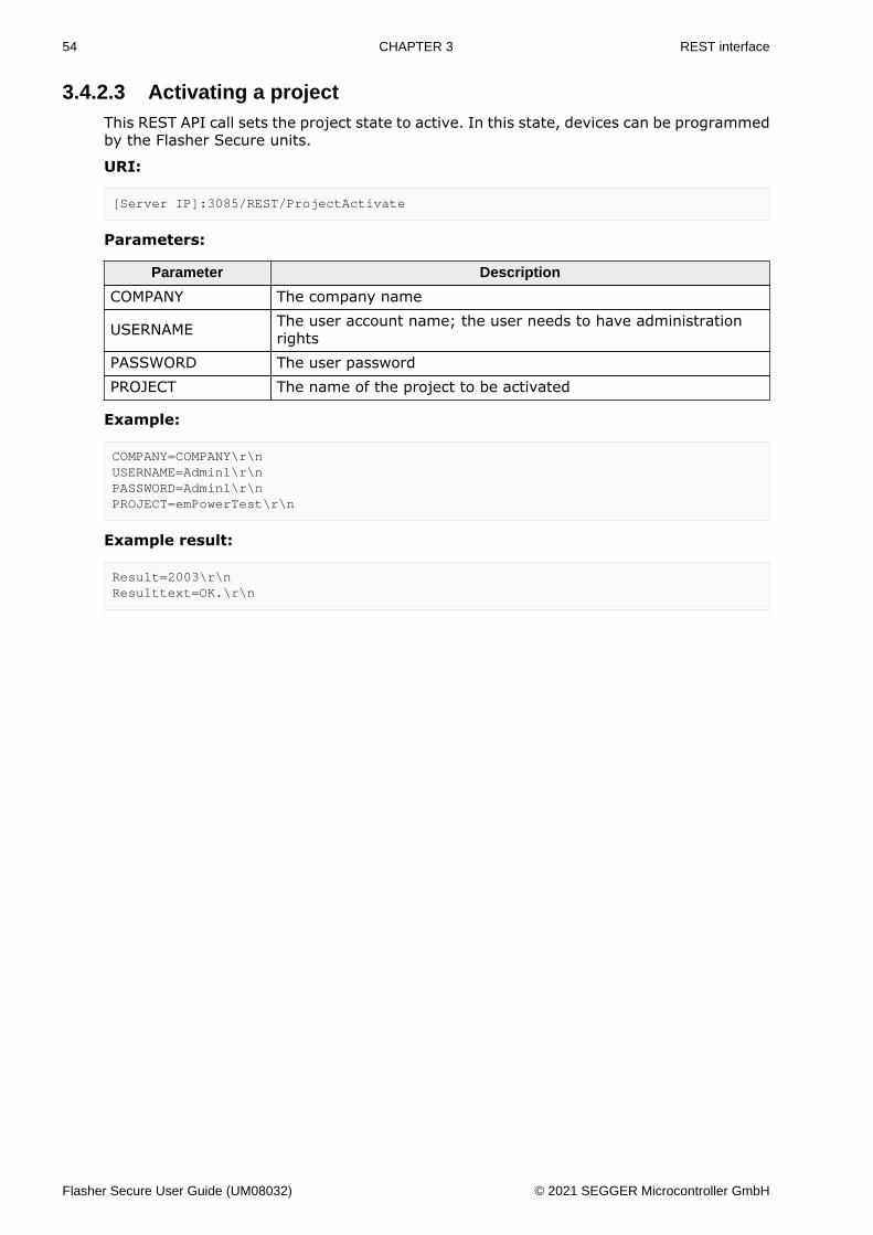
3.4.2.3 Activating a projectThis REST API call sets the project state to active. In this state, devices can be programmedby the Flasher Secure units.
URI:
[Server IP]:3085/REST/ProjectActivate
Parameters:
Parameter Description
COMPANY The company name
USERNAME The user account name; the user needs to have administrationrights
PASSWORD The user passwordPROJECT The name of the project to be activated
Example:
COMPANY=COMPANY\r\nUSERNAME=Admin1\r\nPASSWORD=Admin1\r\nPROJECT=emPowerTest\r\n
Example result:
Result=2003\r\nResulttext=OK.\r\n
Flasher Secure User Guide (UM08032) © 2021 SEGGER Microcontroller GmbH
55 CHAPTER 3 REST interface
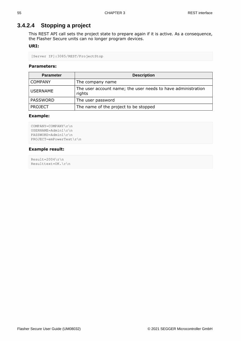
3.4.2.4 Stopping a projectThis REST API call sets the project state to prepare again if it is active. As a consequence,the Flasher Secure units can no longer program devices.
URI:
[Server IP]:3085/REST/ProjectStop
Parameters:
Parameter Description
COMPANY The company name
USERNAME The user account name; the user needs to have administrationrights
PASSWORD The user passwordPROJECT The name of the project to be stopped
Example:
COMPANY=COMPANY\r\nUSERNAME=Admin1\r\nPASSWORD=Admin1\r\nPROJECT=emPowerTest\r\n
Example result:
Result=2004\r\nResulttext=OK.\r\n
Flasher Secure User Guide (UM08032) © 2021 SEGGER Microcontroller GmbH
56 CHAPTER 3 REST interface
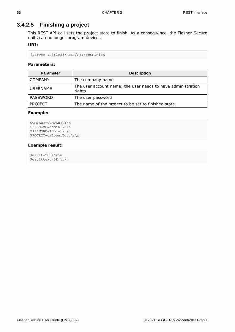
3.4.2.5 Finishing a projectThis REST API call sets the project state to finish. As a consequence, the Flasher Secureunits can no longer program devices.
URI:
[Server IP]:3085/REST/ProjectFinish
Parameters:
Parameter Description
COMPANY The company name
USERNAME The user account name; the user needs to have administrationrights
PASSWORD The user passwordPROJECT The name of the project to be set to finished state
Example:
COMPANY=COMPANY\r\nUSERNAME=Admin1\r\nPASSWORD=Admin1\r\nPROJECT=emPowerTest\r\n
Example result:
Result=2001\r\nResulttext=OK.\r\n
Flasher Secure User Guide (UM08032) © 2021 SEGGER Microcontroller GmbH

57 CHAPTER 3 REST interface
3.4.2.6 Moving a project to prepare stateThis REST API call sets the project state from finish back to prepare. This way, a projectcan be reactivated for further programming if a production lot was completed previously.
URI:
[Server IP]:3085/REST/ProjectMovePrepare
Parameters:
Parameter Description
COMPANY The company name
USERNAME The user account name; the user needs to have administrationrights
PASSWORD The user passwordPROJECT The name of the project to be set to prepare state
Example:
COMPANY=COMPANY\r\nUSERNAME=Admin1\r\nPASSWORD=Admin1\r\nPROJECT=emPowerTest\r\n
Example result:
Result=2002\r\nResulttext=OK.\r\n
Flasher Secure User Guide (UM08032) © 2021 SEGGER Microcontroller GmbH
58 CHAPTER 3 REST interface
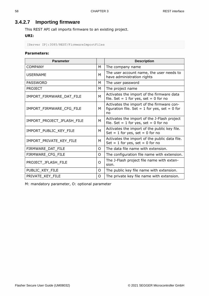
3.4.2.7 Importing firmwareThis REST API call imports firmware to an existing project.
URI:
[Server IP]:3085/REST/FirmwareImportFiles
Parameters:
Parameter Description
COMPANY M The company name
USERNAME M The user account name, the user needs tohave administration rights
PASSWORD M The user passwordPROJECT M The project name
IMPORT_FIRMWARE_DAT_FILE M Activates the import of the firmware datafile. Set = 1 for yes, set = 0 for no
IMPORT_FIRMWARE_CFG_FILE MActivates the import of the firmware con-figuration file. Set = 1 for yes, set = 0 forno
IMPORT_PROJECT_JFLASH_FILE M Activates the import of the J-Flash projectfile. Set = 1 for yes, set = 0 for no
IMPORT_PUBLIC_KEY_FILE M Activates the import of the public key file.Set = 1 for yes, set = 0 for no
IMPORT_PRIVATE_KEY_FILE M Activates the import of the public data file.Set = 1 for yes, set = 0 for no
FIRMWARE_DAT_FILE O The data file name with extension.FIRMWARE_CFG_FILE O The configuration file name with extension.
PROJECT_JFLASH_FILE O The J-Flash project file name with exten-sion.
PUBLIC_KEY_FILE O The public key file name with extension.PRIVATE_KEY_FILE O The private key file name with extension.
M: mandatory parameter, O: optional parameter
Flasher Secure User Guide (UM08032) © 2021 SEGGER Microcontroller GmbH

59 CHAPTER 3 REST interface
Example:
COMPANY=COMPANY\r\nUSERNAME=Admin1\r\nPASSWORD=Admin1\r\nPROJECT=emPowerTest\r\nTOTAL_NUMBER_DEVICES=100\r\nREPROGRAMMING=5\r\nFAILURE_RATE=2\r\nSTART_SERIALNUMBER=10010000\r\nSMTP_SERVER=smtp.company.com\r\nSMTP_AUTH_USERNAME=FlasherSecureServer\r\nSMTP_AUTH_PASSWORD=87654321\r\[email protected]\r\nNOTIFICATION_TO_USERNAME=Admin\r\nNOTIFY_MANUFACTURER_BLOCKED=1\r\nNOTIFY_PROJECT_FINISHED=0\r\n
Example result:
Result=4000\r\nResulttext=OK.\r\n
Flasher Secure User Guide (UM08032) © 2021 SEGGER Microcontroller GmbH
60 CHAPTER 3 REST interface
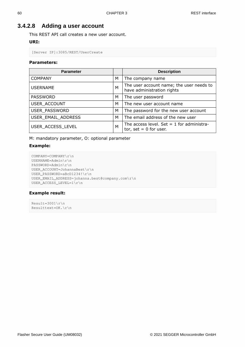
3.4.2.8 Adding a user accountThis REST API call creates a new user account.
URI:
[Server IP]:3085/REST/UserCreate
Parameters:
Parameter Description
COMPANY M The company name
USERNAME M The user account name; the user needs tohave administration rights
PASSWORD M The user passwordUSER_ACCOUNT M The new user account nameUSER_PASSWORD M The password for the new user accountUSER_EMAIL_ADDRESS M The email address of the new user
USER_ACCESS_LEVEL M The access level. Set = 1 for administra-tor, set = 0 for user.
M: mandatory parameter, O: optional parameter
Example:
COMPANY=COMPANY\r\nUSERNAME=Admin\r\nPASSWORD=Admin\r\nUSER_ACCOUNT=JohannaBest\r\nUSER_PASSWORD=aBcD1234!\r\[email protected]\r\nUSER_ACCESS_LEVEL=1\r\n
Example result:
Result=3001\r\nResulttext=OK.\r\n
Flasher Secure User Guide (UM08032) © 2021 SEGGER Microcontroller GmbH
61 CHAPTER 3 REST interface
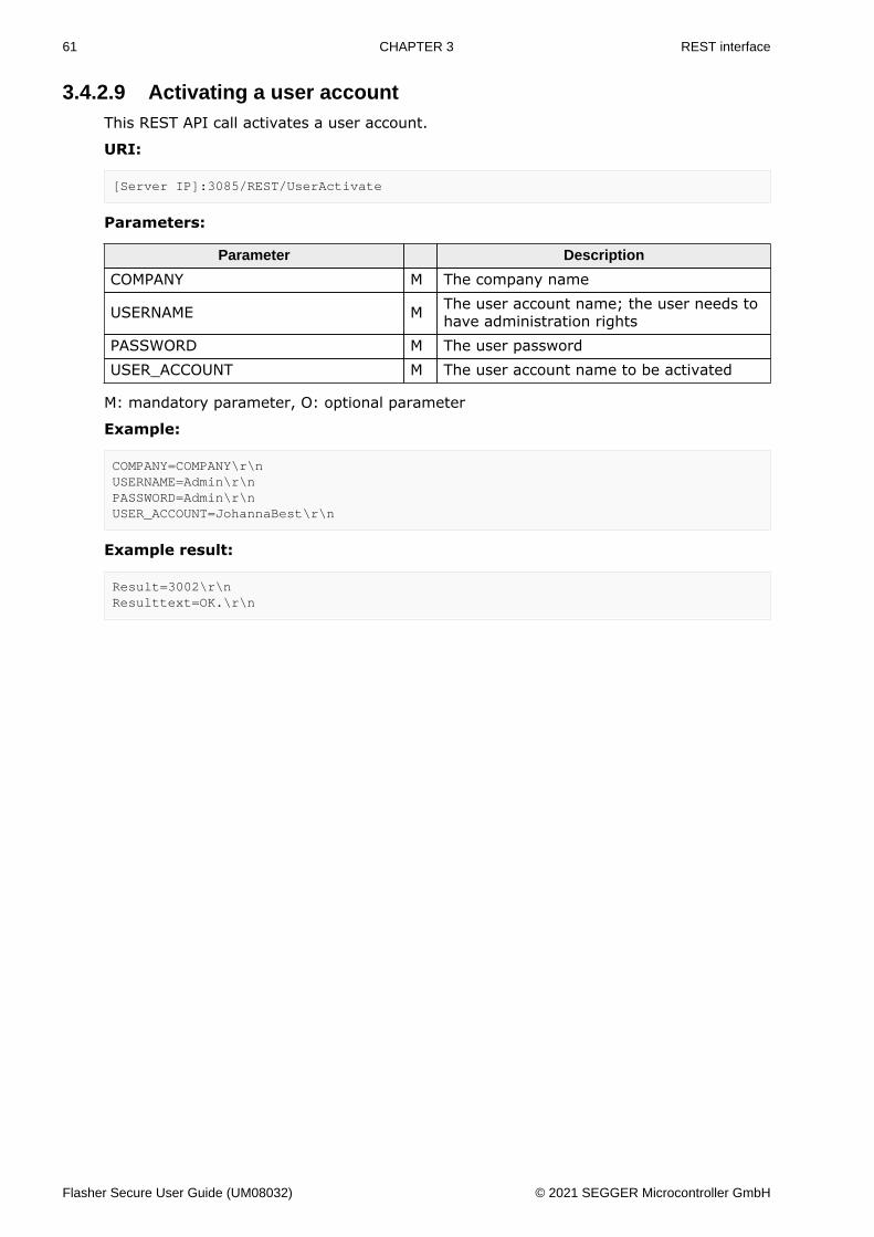
3.4.2.9 Activating a user accountThis REST API call activates a user account.
URI:
[Server IP]:3085/REST/UserActivate
Parameters:
Parameter Description
COMPANY M The company name
USERNAME M The user account name; the user needs tohave administration rights
PASSWORD M The user passwordUSER_ACCOUNT M The user account name to be activated
M: mandatory parameter, O: optional parameter
Example:
COMPANY=COMPANY\r\nUSERNAME=Admin\r\nPASSWORD=Admin\r\nUSER_ACCOUNT=JohannaBest\r\n
Example result:
Result=3002\r\nResulttext=OK.\r\n
Flasher Secure User Guide (UM08032) © 2021 SEGGER Microcontroller GmbH
62 CHAPTER 3 REST interface
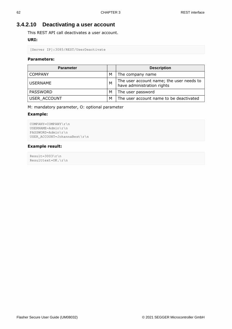
3.4.2.10 Deactivating a user accountThis REST API call deactivates a user account.
URI:
[Server IP]:3085/REST/UserDeactivate
Parameters:
Parameter Description
COMPANY M The company name
USERNAME M The user account name; the user needs tohave administration rights
PASSWORD M The user passwordUSER_ACCOUNT M The user account name to be deactivated
M: mandatory parameter, O: optional parameter
Example:
COMPANY=COMPANY\r\nUSERNAME=Admin\r\nPASSWORD=Admin\r\nUSER_ACCOUNT=JohannaBest\r\n
Example result:
Result=3003\r\nResulttext=OK.\r\n
Flasher Secure User Guide (UM08032) © 2021 SEGGER Microcontroller GmbH
63 CHAPTER 3 REST interface
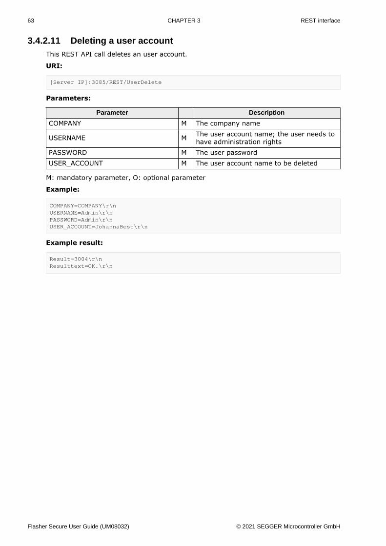
3.4.2.11 Deleting a user accountThis REST API call deletes an user account.
URI:
[Server IP]:3085/REST/UserDelete
Parameters:
Parameter Description
COMPANY M The company name
USERNAME M The user account name; the user needs tohave administration rights
PASSWORD M The user passwordUSER_ACCOUNT M The user account name to be deleted
M: mandatory parameter, O: optional parameter
Example:
COMPANY=COMPANY\r\nUSERNAME=Admin\r\nPASSWORD=Admin\r\nUSER_ACCOUNT=JohannaBest\r\n
Example result:
Result=3004\r\nResulttext=OK.\r\n
Flasher Secure User Guide (UM08032) © 2021 SEGGER Microcontroller GmbH
64 CHAPTER 3 REST interface
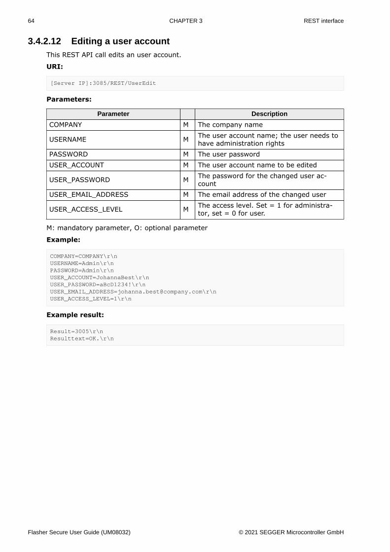
3.4.2.12 Editing a user accountThis REST API call edits an user account.
URI:
[Server IP]:3085/REST/UserEdit
Parameters:
Parameter Description
COMPANY M The company name
USERNAME M The user account name; the user needs tohave administration rights
PASSWORD M The user passwordUSER_ACCOUNT M The user account name to be edited
USER_PASSWORD M The password for the changed user ac-count
USER_EMAIL_ADDRESS M The email address of the changed user
USER_ACCESS_LEVEL M The access level. Set = 1 for administra-tor, set = 0 for user.
M: mandatory parameter, O: optional parameter
Example:
COMPANY=COMPANY\r\nUSERNAME=Admin\r\nPASSWORD=Admin\r\nUSER_ACCOUNT=JohannaBest\r\nUSER_PASSWORD=aBcD1234!\r\[email protected]\r\nUSER_ACCESS_LEVEL=1\r\n
Example result:
Result=3005\r\nResulttext=OK.\r\n
Flasher Secure User Guide (UM08032) © 2021 SEGGER Microcontroller GmbH

65 CHAPTER 3 REST interface
3.4.2.13 Adding a manufacturer accountThis REST API call adds a manufacturer account.
URI:
[Server IP]:3085/REST/ManufacturerCreate
Parameters:
Parameter Description
COMPANY M The company name
USERNAME M The user account name; the user needs tohave administration rights
PASSWORD M The user password
PROJECT M The project for which the manufacturer ac-count shall be created
MANUFACTURER M The manufacturer account name to beadded
MANUFACTURER_PASSWORD M The password for the user manufacturer
DEVICES M The number of devices allowed to be pro-grammed
M: mandatory parameter, O: optional parameter
Example:
COMPANY=COMPANY\r\nUSERNAME=Admin\r\nPASSWORD=Admin\r\nPROJECT=testProject\r\nMANUFACTURER=MySuperManufacturer\r\nMANUFACTURER_PASSWORD=aBcD1234!\r\nDEVICES=100000\r\n
Example result:
Result=5000\r\nResulttext=OK.\r\n
Flasher Secure User Guide (UM08032) © 2021 SEGGER Microcontroller GmbH
66 CHAPTER 3 REST interface
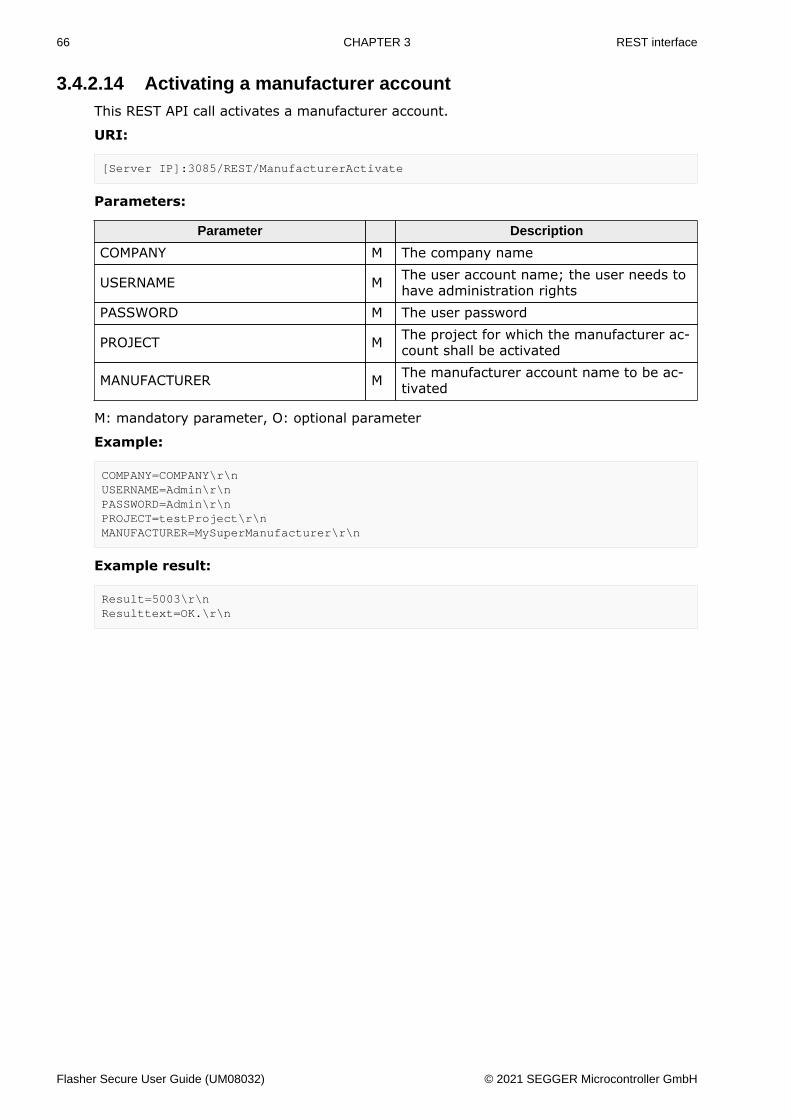
3.4.2.14 Activating a manufacturer accountThis REST API call activates a manufacturer account.
URI:
[Server IP]:3085/REST/ManufacturerActivate
Parameters:
Parameter Description
COMPANY M The company name
USERNAME M The user account name; the user needs tohave administration rights
PASSWORD M The user password
PROJECT M The project for which the manufacturer ac-count shall be activated
MANUFACTURER M The manufacturer account name to be ac-tivated
M: mandatory parameter, O: optional parameter
Example:
COMPANY=COMPANY\r\nUSERNAME=Admin\r\nPASSWORD=Admin\r\nPROJECT=testProject\r\nMANUFACTURER=MySuperManufacturer\r\n
Example result:
Result=5003\r\nResulttext=OK.\r\n
Flasher Secure User Guide (UM08032) © 2021 SEGGER Microcontroller GmbH

67 CHAPTER 3 REST interface
3.4.2.15 Deactivating a manufacturer accountThis REST API call deactivates a manufacturer account.
URI:
[Server IP]:3085/REST/ManufacturerDeactivate
Parameters:
Parameter Description
COMPANY M The company name
USERNAME M The user account name; the user needs tohave administration rights
PASSWORD M The user password
PROJECT M The project for which the manufacturer ac-count shall be deactivated
MANUFACTURER M The manufacturer account name to be de-activated
M: mandatory parameter, O: optional parameter
Example:
COMPANY=COMPANY\r\nUSERNAME=Admin\r\nPASSWORD=Admin\r\nPROJECT=testProject\r\nMANUFACTURER=MySuperManufacturer\r\n
Example result:
Result=5004\r\nResulttext=OK.\r\n
Flasher Secure User Guide (UM08032) © 2021 SEGGER Microcontroller GmbH

68 CHAPTER 3 REST interface
3.4.2.16 Deleting a manufacturer accountThis REST API call deletes a manufacturer account.
URI:
[Server IP]:3085/REST/ManufacturerDelete
Parameters:
Parameter Description
COMPANY M The company name.
USERNAME M The user account name; the user needs tohave administration rights
PASSWORD M The user password
PROJECT M The project for which the manufacturer ac-count shall be deleted
MANUFACTURER M The manufacturer account name to bedeleted
M: mandatory parameter, O: optional parameter
Example:
COMPANY=COMPANY\r\nUSERNAME=Admin\r\nPASSWORD=Admin\r\nPROJECT=testProject\r\nMANUFACTURER=MySuperManufacturer\r\n
Example result:
Result=5005\r\nResulttext=OK.\r\n
Flasher Secure User Guide (UM08032) © 2021 SEGGER Microcontroller GmbH
69 CHAPTER 3 REST interface
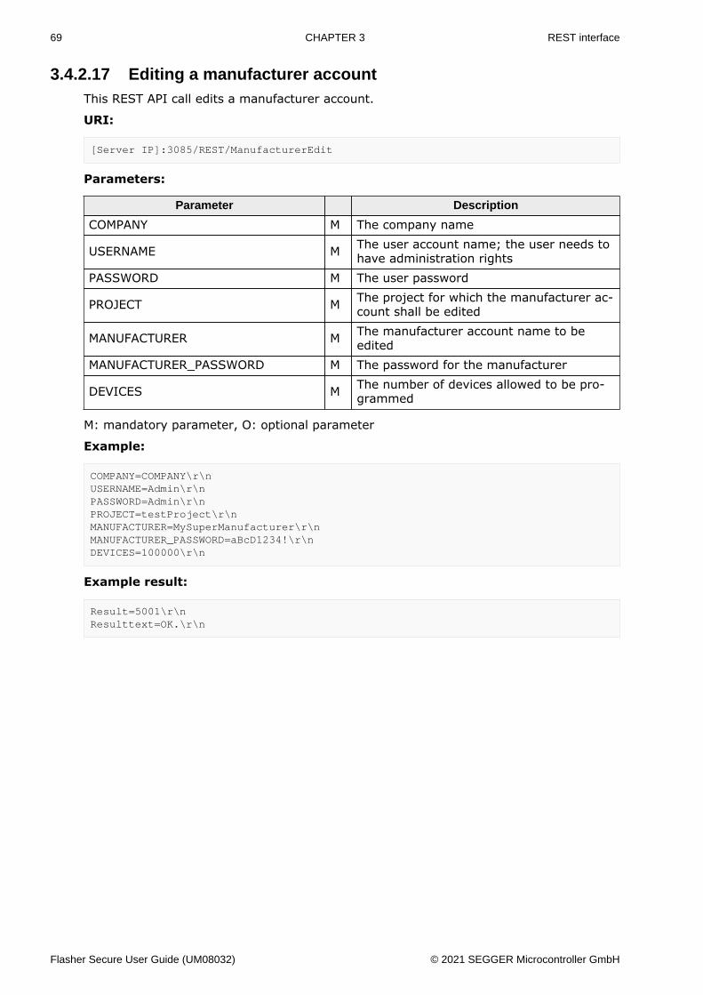
3.4.2.17 Editing a manufacturer accountThis REST API call edits a manufacturer account.
URI:
[Server IP]:3085/REST/ManufacturerEdit
Parameters:
Parameter Description
COMPANY M The company name
USERNAME M The user account name; the user needs tohave administration rights
PASSWORD M The user password
PROJECT M The project for which the manufacturer ac-count shall be edited
MANUFACTURER M The manufacturer account name to beedited
MANUFACTURER_PASSWORD M The password for the manufacturer
DEVICES M The number of devices allowed to be pro-grammed
M: mandatory parameter, O: optional parameter
Example:
COMPANY=COMPANY\r\nUSERNAME=Admin\r\nPASSWORD=Admin\r\nPROJECT=testProject\r\nMANUFACTURER=MySuperManufacturer\r\nMANUFACTURER_PASSWORD=aBcD1234!\r\nDEVICES=100000\r\n
Example result:
Result=5001\r\nResulttext=OK.\r\n
Flasher Secure User Guide (UM08032) © 2021 SEGGER Microcontroller GmbH
70 CHAPTER 3 REST interface
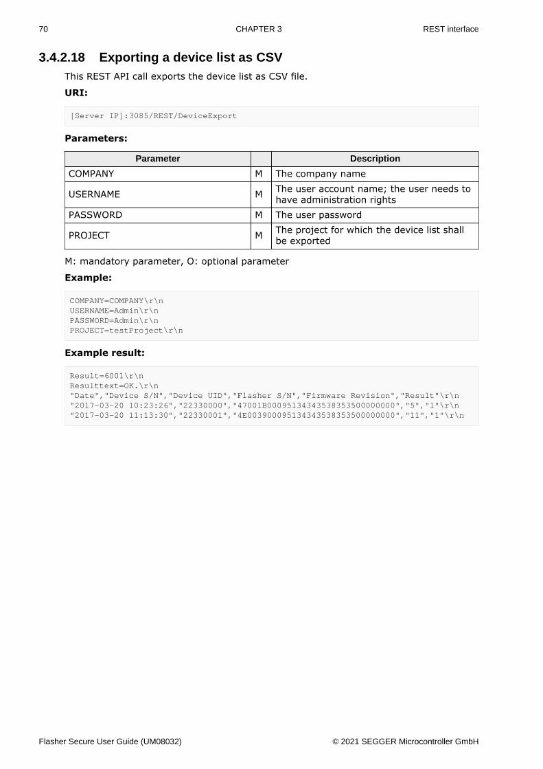
3.4.2.18 Exporting a device list as CSVThis REST API call exports the device list as CSV file.
URI:
[Server IP]:3085/REST/DeviceExport
Parameters:
Parameter Description
COMPANY M The company name
USERNAME M The user account name; the user needs tohave administration rights
PASSWORD M The user password
PROJECT M The project for which the device list shallbe exported
M: mandatory parameter, O: optional parameter
Example:
COMPANY=COMPANY\r\nUSERNAME=Admin\r\nPASSWORD=Admin\r\nPROJECT=testProject\r\n
Example result:
Result=6001\r\nResulttext=OK.\r\n"Date","Device S/N","Device UID","Flasher S/N","Firmware Revision","Result"\r\n"2017-03-20 10:23:26","22330000","47001B00095134343538353500000000","5","1"\r\n"2017-03-20 11:13:30","22330001","4E003900095134343538353500000000","11","1"\r\n
Flasher Secure User Guide (UM08032) © 2021 SEGGER Microcontroller GmbH
71 CHAPTER 3 REST interface
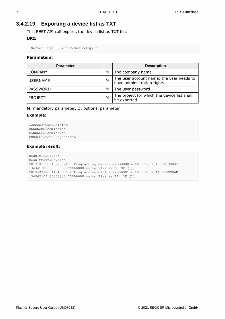
3.4.2.19 Exporting a device list as TXTThis REST API call exports the device list as TXT file.
URI:
[Server IP]:3085/REST/DeviceExport
Parameters:
Parameter Description
COMPANY M The company name
USERNAME M The user account name; the user needs tohave administration rights
PASSWORD M The user password
PROJECT M The project for which the device list shallbe exported
M: mandatory parameter, O: optional parameter
Example:
COMPANY=COMPANY\r\nUSERNAME=Admin\r\nPASSWORD=Admin\r\nPROJECT=testProject\r\n
Example result:
Result=6001\r\nResulttext=OK.\r\n2017-03-20 10:23:26 - Programming device 22330000 with unique ID 001B0047 34345109 35353835 00000000 using Flasher 5: OK (1)2017-03-20 11:13:30 - Programming device 22330001 with unique ID 0039004E 34345109 35353835 00000000 using Flasher 11: OK (1)
Flasher Secure User Guide (UM08032) © 2021 SEGGER Microcontroller GmbH

72 CHAPTER 3 REST interface
3.4.3 REST API Result CodesThe table below list all result codes for successful REST API calls.
Code Meaning
Project actions
2000 Project created successfully2001 Project state set to finish successfully2002 Project state set to prepare successfully2003 Project state set to active successfully2004 Project state set to prepare from active (stop) successfully2005 Project deleted successfully
User account actions
3001 User account created successfully3002 User account activated successfully3003 User account deactivated successfully3004 User account deleted successfully3005 User account edited successfully
Firmware actions
4000 Firmware imported successfullyManufacturer account actions
5000 Manufacturer account created successfully5001 Manufacturer account edited successfully5002 Manufacturer account success rate reset successfully5003 Manufacturer account activated successfully5004 Manufacturer account deactivated successfully5005 Manufacturer account deleted successfully
Device actions
6002 Device list exported as CSV file successfully6003 Device list exported as TXT file successfully
Flasher Secure User Guide (UM08032) © 2021 SEGGER Microcontroller GmbH
73 CHAPTER 3 REST interface
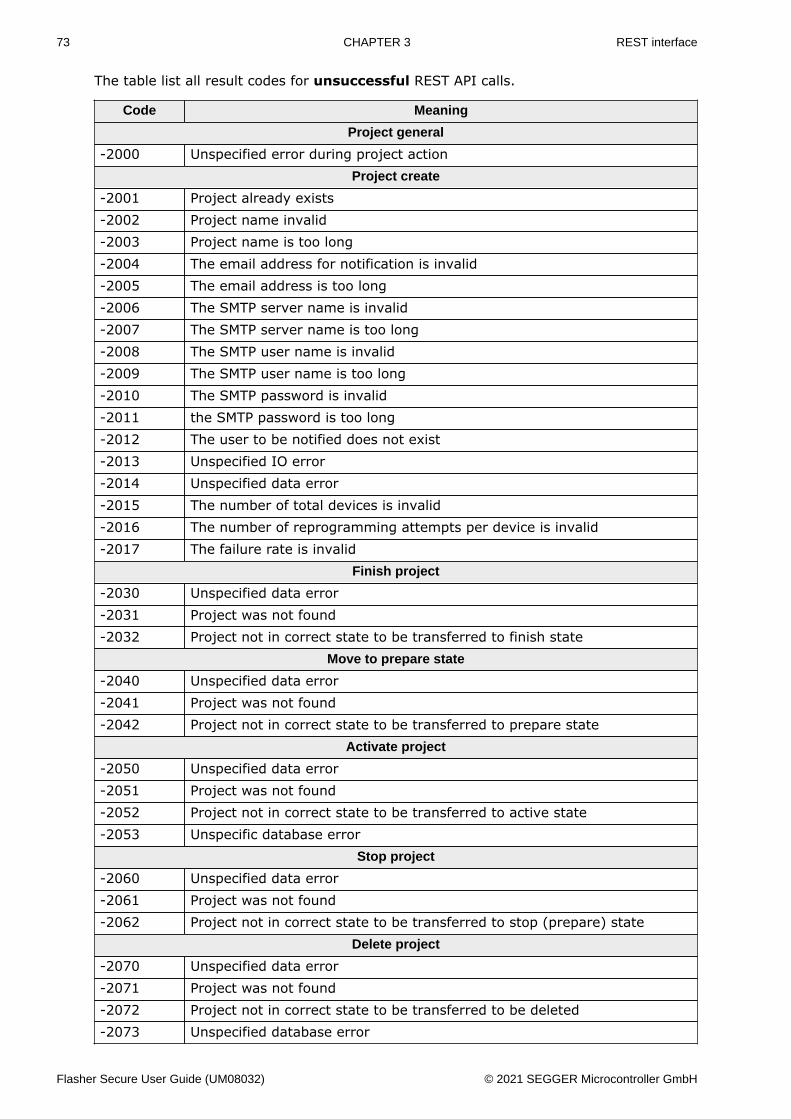
The table list all result codes for unsuccessful REST API calls.
Code Meaning
Project general
-2000 Unspecified error during project actionProject create
-2001 Project already exists-2002 Project name invalid-2003 Project name is too long-2004 The email address for notification is invalid-2005 The email address is too long-2006 The SMTP server name is invalid-2007 The SMTP server name is too long-2008 The SMTP user name is invalid-2009 The SMTP user name is too long-2010 The SMTP password is invalid-2011 the SMTP password is too long-2012 The user to be notified does not exist-2013 Unspecified IO error-2014 Unspecified data error-2015 The number of total devices is invalid-2016 The number of reprogramming attempts per device is invalid-2017 The failure rate is invalid
Finish project
-2030 Unspecified data error-2031 Project was not found-2032 Project not in correct state to be transferred to finish state
Move to prepare state
-2040 Unspecified data error-2041 Project was not found-2042 Project not in correct state to be transferred to prepare state
Activate project
-2050 Unspecified data error-2051 Project was not found-2052 Project not in correct state to be transferred to active state-2053 Unspecific database error
Stop project
-2060 Unspecified data error-2061 Project was not found-2062 Project not in correct state to be transferred to stop (prepare) state
Delete project
-2070 Unspecified data error-2071 Project was not found-2072 Project not in correct state to be transferred to be deleted-2073 Unspecified database error
Flasher Secure User Guide (UM08032) © 2021 SEGGER Microcontroller GmbH

74 CHAPTER 3 REST interface
Code Meaning
-2074 Unspecified IO error
Flasher Secure User Guide (UM08032) © 2021 SEGGER Microcontroller GmbH
75 CHAPTER 3 REST interface
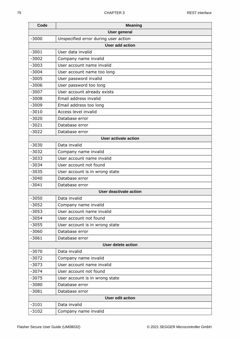
Code Meaning
User general
-3000 Unspecified error during user actionUser add action
-3001 User data invalid-3002 Company name invalid-3003 User account name invalid-3004 User account name too long-3005 User password invalid-3006 User password too long-3007 User account already exists-3008 Email address invalid-3009 Email address too long-3010 Access level invalid-3020 Database error-3021 Database error-3022 Database error
User activate action
-3030 Data invalid-3032 Company name invalid-3033 User account name invalid-3034 User account not found-3035 User account is in wrong state-3040 Database error-3041 Database error
User deactivate action
-3050 Data invalid-3052 Company name invalid-3053 User account name invalid-3054 User account not found-3055 User account is in wrong state-3060 Database error-3061 Database error
User delete action
-3070 Data invalid-3072 Company name invalid-3073 User account name invalid-3074 User account not found-3075 User account is in wrong state-3080 Database error-3081 Database error
User edit action
-3101 Data invalid-3102 Company name invalid
Flasher Secure User Guide (UM08032) © 2021 SEGGER Microcontroller GmbH
76 CHAPTER 3 REST interface
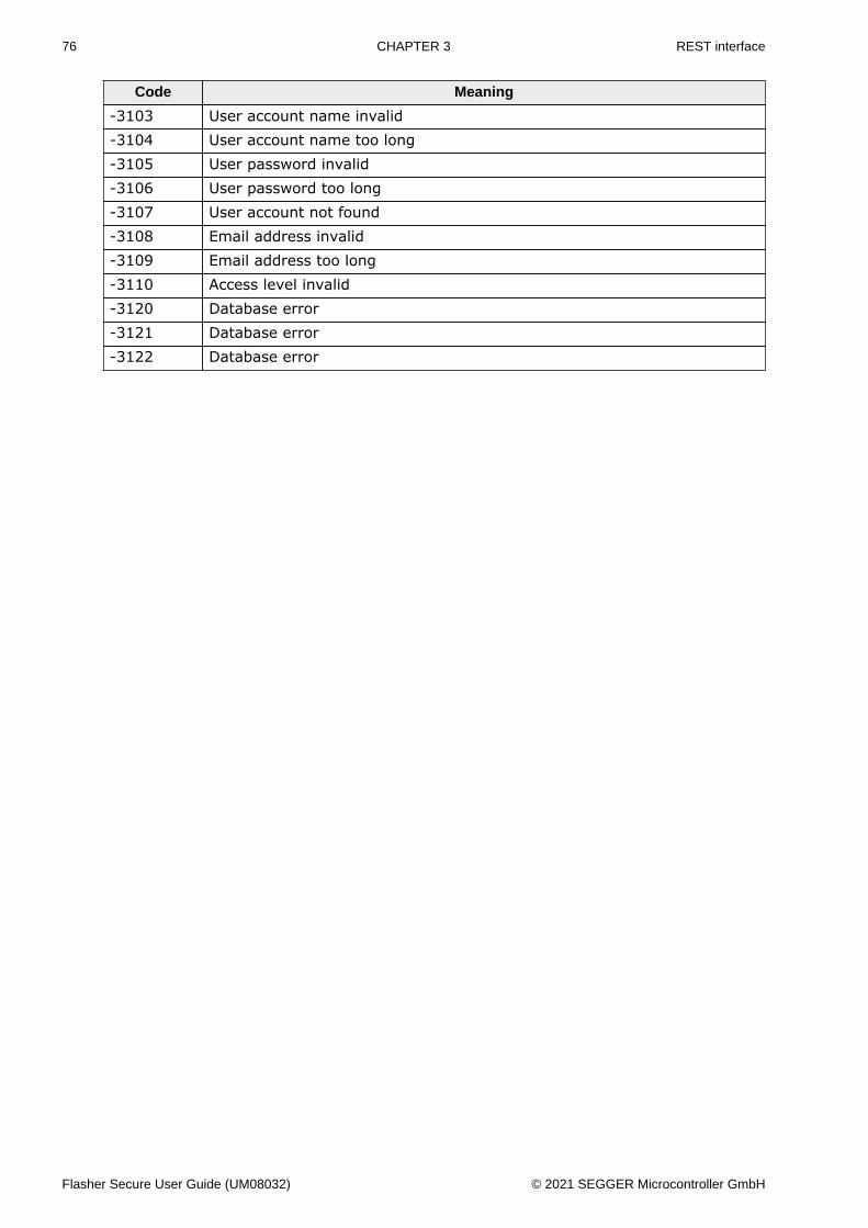
Code Meaning
-3103 User account name invalid-3104 User account name too long-3105 User password invalid-3106 User password too long-3107 User account not found-3108 Email address invalid-3109 Email address too long-3110 Access level invalid-3120 Database error-3121 Database error-3122 Database error
Flasher Secure User Guide (UM08032) © 2021 SEGGER Microcontroller GmbH
77 CHAPTER 3 REST interface
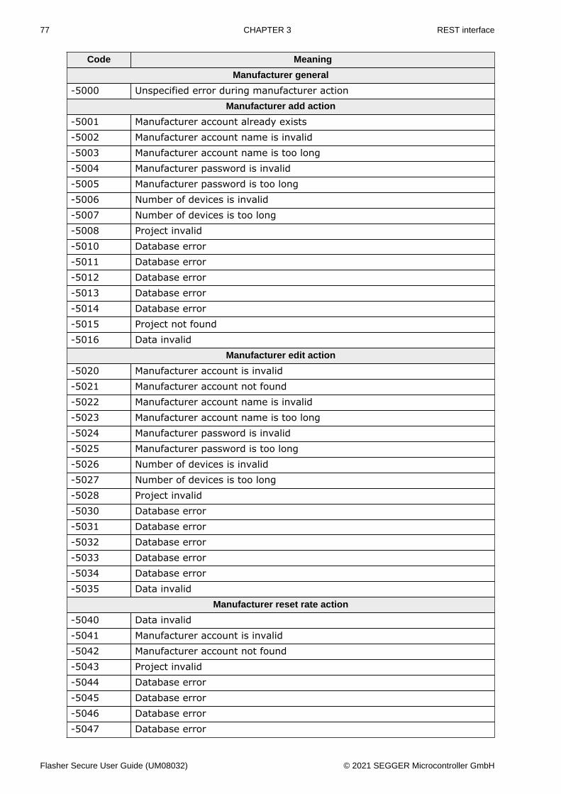
Code Meaning
Manufacturer general
-5000 Unspecified error during manufacturer actionManufacturer add action
-5001 Manufacturer account already exists-5002 Manufacturer account name is invalid-5003 Manufacturer account name is too long-5004 Manufacturer password is invalid-5005 Manufacturer password is too long-5006 Number of devices is invalid-5007 Number of devices is too long-5008 Project invalid-5010 Database error-5011 Database error-5012 Database error-5013 Database error-5014 Database error-5015 Project not found-5016 Data invalid
Manufacturer edit action
-5020 Manufacturer account is invalid-5021 Manufacturer account not found-5022 Manufacturer account name is invalid-5023 Manufacturer account name is too long-5024 Manufacturer password is invalid-5025 Manufacturer password is too long-5026 Number of devices is invalid-5027 Number of devices is too long-5028 Project invalid-5030 Database error-5031 Database error-5032 Database error-5033 Database error-5034 Database error-5035 Data invalid
Manufacturer reset rate action
-5040 Data invalid-5041 Manufacturer account is invalid-5042 Manufacturer account not found-5043 Project invalid-5044 Database error-5045 Database error-5046 Database error-5047 Database error
Flasher Secure User Guide (UM08032) © 2021 SEGGER Microcontroller GmbH
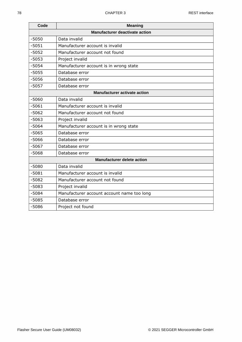
78 CHAPTER 3 REST interface
Code Meaning
Manufacturer deactivate action
-5050 Data invalid-5051 Manufacturer account is invalid-5052 Manufacturer account not found-5053 Project invalid-5054 Manufacturer account is in wrong state-5055 Database error-5056 Database error-5057 Database error
Manufacturer activate action
-5060 Data invalid-5061 Manufacturer account is invalid-5062 Manufacturer account not found-5063 Project invalid-5064 Manufacturer account is in wrong state-5065 Database error-5066 Database error-5067 Database error-5068 Database error
Manufacturer delete action
-5080 Data invalid-5081 Manufacturer account is invalid-5082 Manufacturer account not found-5083 Project invalid-5084 Manufacturer account account name too long-5085 Database error-5086 Project not found
Flasher Secure User Guide (UM08032) © 2021 SEGGER Microcontroller GmbH
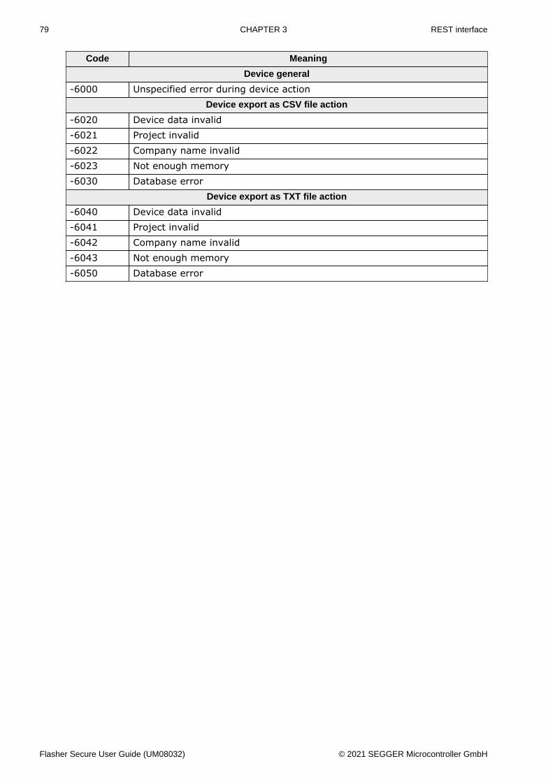
79 CHAPTER 3 REST interface
Code Meaning
Device general
-6000 Unspecified error during device actionDevice export as CSV file action
-6020 Device data invalid-6021 Project invalid-6022 Company name invalid-6023 Not enough memory-6030 Database error
Device export as TXT file action
-6040 Device data invalid-6041 Project invalid-6042 Company name invalid-6043 Not enough memory-6050 Database error
Flasher Secure User Guide (UM08032) © 2021 SEGGER Microcontroller GmbH
Chapter 4 Flasher Secure unit
The Flasher Secure unit is based on the SEGGER Flasher unit, so it generally supports thesame devices as the Flashers do. However, devices that do not provide a UID or a vendorspecific secure programming solution are not supported.
Flasher Secure User Guide (UM08032) © 2021 SEGGER Microcontroller GmbH
81 CHAPTER 4 General
4.1 GeneralThe Flasher Secure unit is the programming unit that is connected to the target device.
Note
The Flasher Secure needs an internet connection or network connection. It needs tobe able to reach the Flasher Secure Server, which provides the signature generationservice.
Flasher Secure User Guide (UM08032) © 2021 SEGGER Microcontroller GmbH
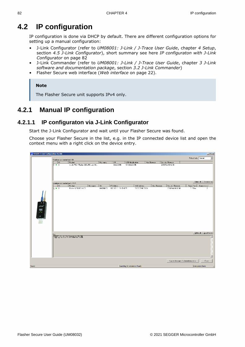
82 CHAPTER 4 IP configuration
4.2 IP configurationIP configuration is done via DHCP by default. There are different configuration options forsetting up a manual configuration:• J-Link Configurator (refer to UM08001: J-Link / J-Trace User Guide, chapter 4 Setup,
section 4.5 J-Link Configurator), short summary see here IP configuraton with J-LinkConfigurator on page 82
• J-Link Commander (refer to UM08001: J-Link / J-Trace User Guide, chapter 3 J-Linksoftware and documentation package, section 3.2 J-Link Commander)
• Flasher Secure web interface (Web interface on page 22).
Note
The Flasher Secure unit supports IPv4 only.
4.2.1 Manual IP configuration
4.2.1.1 IP configuraton via J-Link ConfiguratorStart the J-Link Configurator and wait until your Flasher Secure was found.
Choose your Flasher Secure in the list, e.g. in the IP connected device list and open thecontext menu with a right click on the device entry.
Flasher Secure User Guide (UM08032) © 2021 SEGGER Microcontroller GmbH

83 CHAPTER 4 IP configuration
Choose the Configure entry in the context menu.
Enter the IP configuration in the pop-up menu and confirm it using the OK button.
Flasher Secure User Guide (UM08032) © 2021 SEGGER Microcontroller GmbH
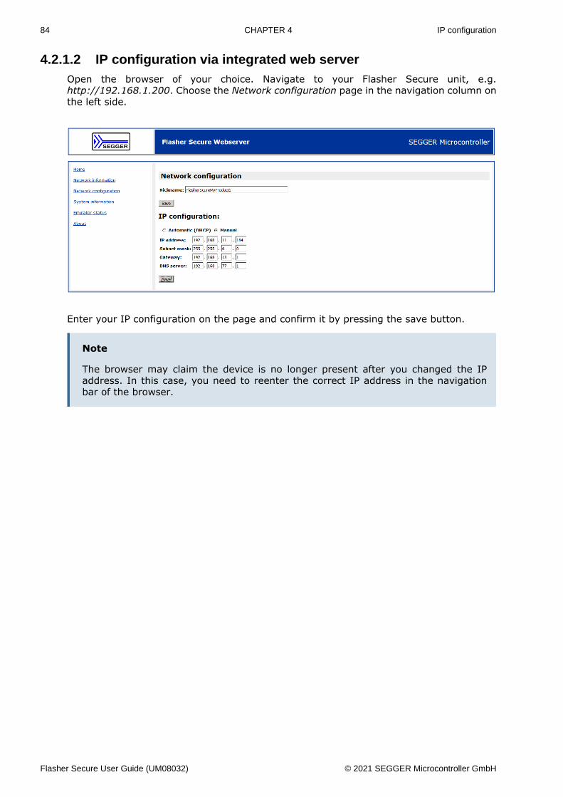
84 CHAPTER 4 IP configuration
4.2.1.2 IP configuration via integrated web serverOpen the browser of your choice. Navigate to your Flasher Secure unit, e.g.http://192.168.1.200. Choose the Network configuration page in the navigation column onthe left side.
Enter your IP configuration on the page and confirm it by pressing the save button.
Note
The browser may claim the device is no longer present after you changed the IPaddress. In this case, you need to reenter the correct IP address in the navigationbar of the browser.
Flasher Secure User Guide (UM08032) © 2021 SEGGER Microcontroller GmbH
85 CHAPTER 4 Project Configuration
4.3 Project Configuration
4.3.1 Configuration filesThe Flasher Secure unit has internal and external storage. The internal storage is about120MB in size and not accessible from the outside. It is used as cache memory for thefirmware and configuration files provided by the server. 16MB of external storage are avail-able for the configuration and log files.
The Flasher Secure needs two configuration files, SECURE.INI and SERVERT.CRT.
A typical configuration file SECURE.INI contains the following information:
[SERVER]Host = "FlasherSecureServer.Company.com"Port = "3110"
[LOGIN]Company = "Company"Project = "MyProject"Username = "MyManufacturer1"Password = "1234abcd!!!!"
Entry Meaning
Server section defines the server settingsHost the server host name or IP addressPort the server portLogin section the login setupCompany the company nameProject the project name
Username the user name for the Flasher Secure Server login; must be oneof the manufacturers logins.
Password the password for the login
Note
The SERVER section defines the host and the port of the server to connect to. Thehost may either be a name or an IP address. If it is a name, a DNS server has to beconfigured in the IP configuration if necessary. The LOGIN section contains the logindata corresponding to a manufacturer account on the server.
The other configuration file, SERVER.CRT, is the server’s TLS certificate. It is used to re-strict the Flasher Secure device to only accept connections to servers using the key in thecertificate (server identity pinning). Although this file is optional, we recommend to use it.It provides a simple and fool-proof way to avoid man-in-the-middle attacks.
Note
The Flasher Secure supports only RSA certificates for the server validation.
4.3.2 Accessing the configuration filesYou have three ways to access the configuration files:• Using the USB MSD mode• Using the built-in FTP server• Using the ASCII command interface via the RS232 connector
Flasher Secure User Guide (UM08032) © 2021 SEGGER Microcontroller GmbH
86 CHAPTER 4 Project Configuration
4.3.2.1 Access via USB MSD modeWhen the Flasher Secure is running in “MSD mode” (Mass Storage Device), the 16MBexternal storage is available as a disk drive. To enter MSD mode, power up the deviceby connecting the USB cable while holding down the Start/Stop button. Keep the buttonpressed for at least another two seconds after power-up.
4.3.2.2 Access via FTPThe Flasher Secure has a built-in FTP server, meaning you can connect to it using an FTPclient of your choice. The FTP server comes with 2 logins.
Login Password Privileges
admin 1234 can read, write, upload, download, deletefiles
anonymous none can only read or download files
Note
These logins cannot be changed.
4.3.2.3 Access via ASCII command protocolThe files can also be written via the ASCII command protocol. Refer to chapter Commandsand replies on page 98 and the included file commands.
Flasher Secure User Guide (UM08032) © 2021 SEGGER Microcontroller GmbH

87 CHAPTER 4 Programming devices
4.4 Programming devicesThe Flasher Secure is typically used to program the target devices in a production setup.Therefore it will erase, flash and secure the target devices in one programming cycle oncethe setup is configured.
The Flasher Secure can be controlled in four ways:• Using the push button on the device• Using the 3-wire handshake interface integrated in the RS232 connector• Using the ASCII command protocol via RS323 or Telnet
For all options, the details are described in chapter Remote Control on page 94.
A typical programming cycle for a target device may look like this:
Input
#AUTO
Flasher Secure Response
#ACK#STATUS:INITIALIZING#STATUS:CONNECTING#STATUS:UNLOCKING#STATUS:ERASING#STATUS:PROGRAMMING#STATUS:VERIFYING#OK (Total 13.993s, Erase 0.483s, Prog 9.183s, Verify 2.514s)
Flasher Secure User Guide (UM08032) © 2021 SEGGER Microcontroller GmbH
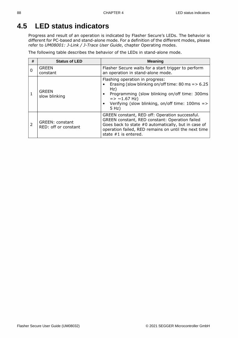
88 CHAPTER 4 LED status indicators
4.5 LED status indicatorsProgress and result of an operation is indicated by Flasher Secure’s LEDs. The behavior isdifferent for PC-based and stand-alone mode. For a definition of the different modes, pleaserefer to UM08001: J-Link / J-Trace User Guide, chapter Operating modes.
The following table describes the behavior of the LEDs in stand-alone mode.
# Status of LED Meaning
0 GREENconstant
Flasher Secure waits for a start trigger to performan operation in stand-alone mode.
1 GREENslow blinking
Flashing operation in progress:• Erasing (slow blinking on/off time: 80 ms => 6.25
Hz)• Programming (slow blinking on/off time: 300ms
=> ~1.67 Hz)• Verifying (slow blinking, on/off time: 100ms =>
5 Hz)
2 GREEN: constantRED: off or constant
GREEN constant, RED off: Operation successful.GREEN constant, RED constant: Operation failedGoes back to state #0 automatically, but in case ofoperation failed, RED remains on until the next timestate #1 is entered.
Flasher Secure User Guide (UM08032) © 2021 SEGGER Microcontroller GmbH
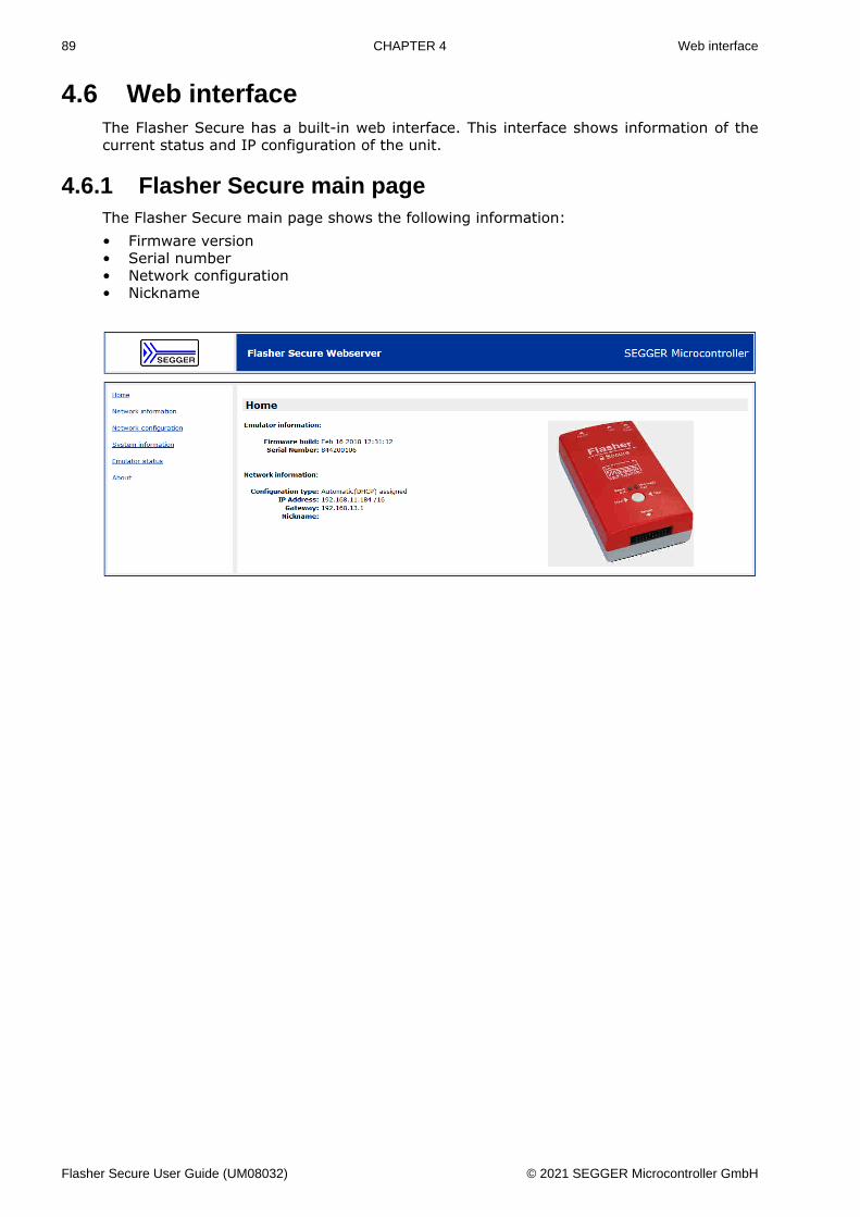
89 CHAPTER 4 Web interface
4.6 Web interfaceThe Flasher Secure has a built-in web interface. This interface shows information of thecurrent status and IP configuration of the unit.
4.6.1 Flasher Secure main pageThe Flasher Secure main page shows the following information:• Firmware version• Serial number• Network configuration• Nickname
Flasher Secure User Guide (UM08032) © 2021 SEGGER Microcontroller GmbH
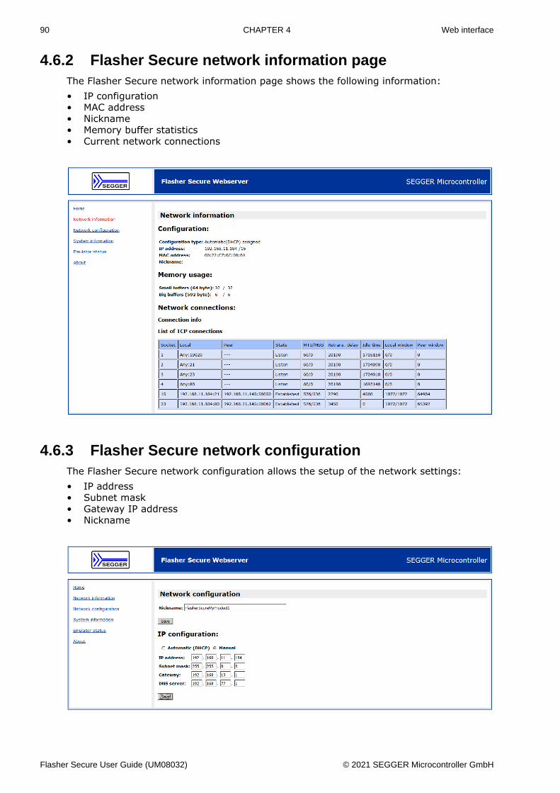
90 CHAPTER 4 Web interface
4.6.2 Flasher Secure network information pageThe Flasher Secure network information page shows the following information:• IP configuration• MAC address• Nickname• Memory buffer statistics• Current network connections
4.6.3 Flasher Secure network configurationThe Flasher Secure network configuration allows the setup of the network settings:• IP address• Subnet mask• Gateway IP address• Nickname
Flasher Secure User Guide (UM08032) © 2021 SEGGER Microcontroller GmbH
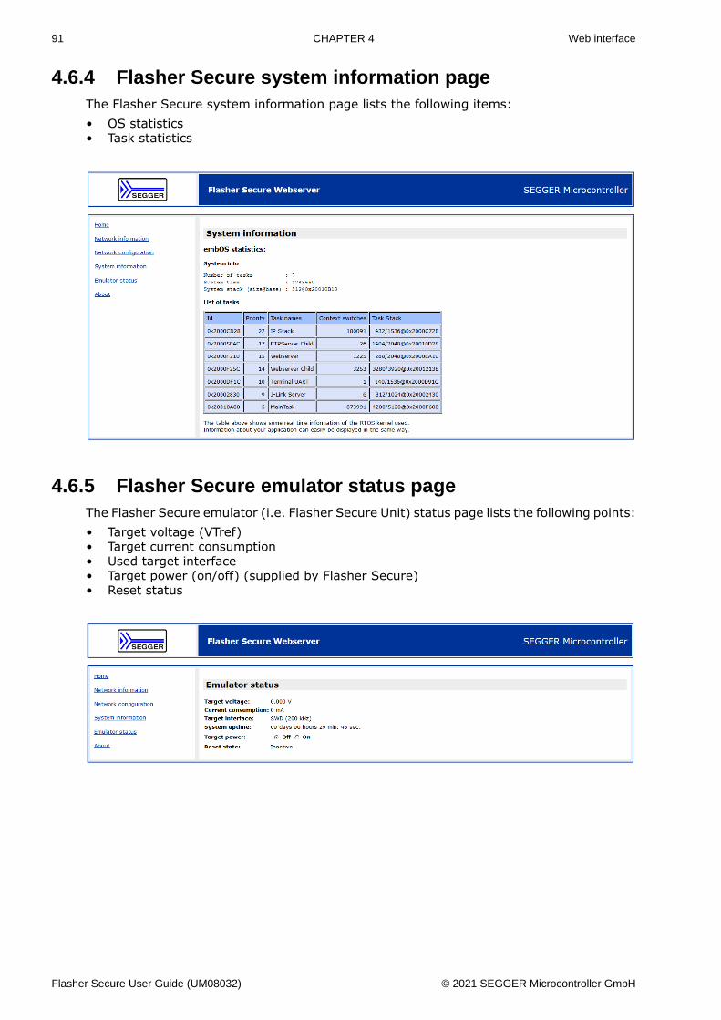
91 CHAPTER 4 Web interface
4.6.4 Flasher Secure system information pageThe Flasher Secure system information page lists the following items:• OS statistics• Task statistics
4.6.5 Flasher Secure emulator status pageThe Flasher Secure emulator (i.e. Flasher Secure Unit) status page lists the following points:• Target voltage (VTref)• Target current consumption• Used target interface• Target power (on/off) (supplied by Flasher Secure)• Reset status
Flasher Secure User Guide (UM08032) © 2021 SEGGER Microcontroller GmbH
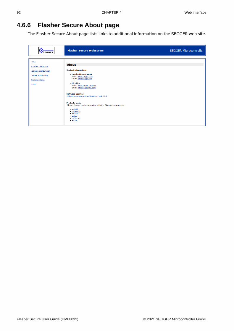
92 CHAPTER 4 Web interface
4.6.6 Flasher Secure About pageThe Flasher Secure About page lists links to additional information on the SEGGER web site.
Flasher Secure User Guide (UM08032) © 2021 SEGGER Microcontroller GmbH

93 CHAPTER 4 Additional Information
4.7 Additional Information
4.7.1 Patch file supportThis feature is currently not supported by Flasher Secure.
4.7.2 PC-based modeThe Flasher Secure can operate in PC-based mode. For further details, please have a lookinto the J-Link Manual (UM08001).
Note
In PC-based mode, the Flasher Secure is able to program target devices using theJ-Flash software. The Flasher Secure programming process, including the signaturegeneration, is only available in stand-alone mode programming.
Flasher Secure User Guide (UM08032) © 2021 SEGGER Microcontroller GmbH
Chapter 5 Remote control
This chapter describes how to control Flasher Secure via the 9-pin serial interface connectoror via the integrated Telnet interface.
Flasher Secure User Guide (UM08032) © 2021 SEGGER Microcontroller GmbH
95 CHAPTER 5 Overview
5.1 OverviewThere are 4 ways to control Flasher Secure operation:• Manual: Programming operation starts when pressing the programming button. The
LEDs serve as visible indicators.• Via Handshake lines: 3 lines on the serial interface are used:
1 line is an input and can be used to start operation,2 lines are outputs and serve as busy and status signals.
• Terminal communication via RS232• Terminal communication via Telnet
Note
The a.m. ways to control Flasher operation work only if Flasher Secure is in standalonemode. In PC-based or MSD mode they have no effect.
Flasher Secure User Guide (UM08032) © 2021 SEGGER Microcontroller GmbH
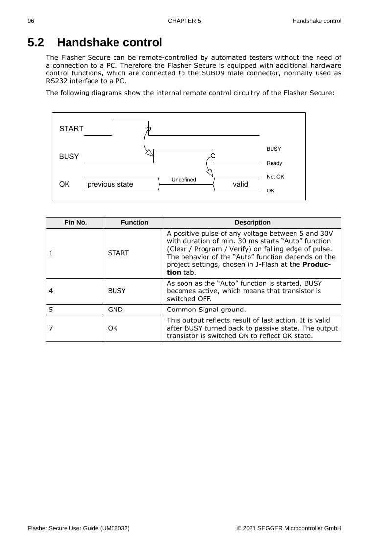
96 CHAPTER 5 Handshake control
5.2 Handshake controlThe Flasher Secure can be remote-controlled by automated testers without the need ofa connection to a PC. Therefore the Flasher Secure is equipped with additional hardwarecontrol functions, which are connected to the SUBD9 male connector, normally used asRS232 interface to a PC.
The following diagrams show the internal remote control circuitry of the Flasher Secure:
Pin No. Function Description
1 START
A positive pulse of any voltage between 5 and 30Vwith duration of min. 30 ms starts “Auto” function(Clear / Program / Verify) on falling edge of pulse.The behavior of the “Auto” function depends on theproject settings, chosen in J-Flash at the Produc-tion tab.
4 BUSYAs soon as the “Auto” function is started, BUSYbecomes active, which means that transistor isswitched OFF.
5 GND Common Signal ground.
7 OKThis output reflects result of last action. It is validafter BUSY turned back to passive state. The outputtransistor is switched ON to reflect OK state.
Flasher Secure User Guide (UM08032) © 2021 SEGGER Microcontroller GmbH
97 CHAPTER 5 ASCII command interface
5.3 ASCII command interface
5.3.1 IntroductionOnce set up using J-Flash, the Flasher Secure can be driven by any application or just asimple terminal using ASCII commands.
Every known command is acknowledged by the Flasher Secure and then executed. Aftercommand execution, the Flasher Secure sends an ASCII reply message.
Note
There are situations where the execution of a known command is rejected with#NACK:ERRxxx if the Flasher Secure is currently busy and the received command isnot allowed to be sent while the Flasher Secure is busy.
5.3.2 General command and reply message format• Any ASCII command has to start with the start delimiter #.• Any ASCII command has to end with simple carriage return (’\r’, ASCII code 13).• Commands can be sent in upper or lower case
5.3.3 General usageReply messages must be considered in each case. In general, a new command must notbe sent before a reply for the last one has been received.
5.3.4 Settings for ASCII interface via RS232The Flasher Secure is driven via a RS232 serial port with the following interface settings:• 9600 baud• 8 data bits• no parity• 1 stop bit
The baud rate can be changed by using the #BAUDRATE command. (see #BAUDRATE onpage 100)
5.3.5 Settings for ASCII interface via TelnetA client application can connect to Flasher via Telnet on port 23. Find below a screenshotof Flasher which is remote controlled via Telnet:
Flasher Secure User Guide (UM08032) © 2021 SEGGER Microcontroller GmbH
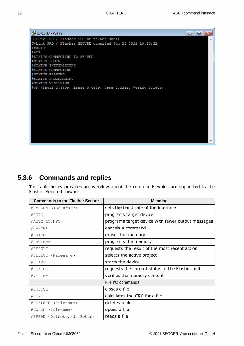
98 CHAPTER 5 ASCII command interface
5.3.6 Commands and repliesThe table below provides an overview about the commands which are supported by theFlasher Secure firmware.
Commands to the Flasher Secure Meaning
#BAUDRATE<Baudrate> sets the baud rate of the interface#AUTO programs target device#AUTO NOINFO programs target device with fewer output messages#CANCEL cancels a command#ERASE erases the memory#PROGRAM programs the memory#RESULT requests the result of the most recent action#SELECT <Filename> selects the active project#START starts the device#STATUS requests the current status of the Flasher unit#VERIFY verifies the memory content
File I/O commands
#FCLOSE closes a file#FCRC calculates the CRC for a file#FDELETE <Filename> deletes a file#FOPEN <Filename> opens a file#FREAD <Offset>,<NumBytes> reads a file
Flasher Secure User Guide (UM08032) © 2021 SEGGER Microcontroller GmbH
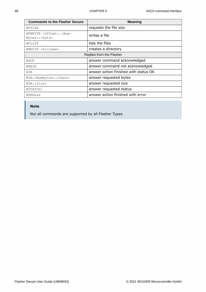
99 CHAPTER 5 ASCII command interface
Commands to the Flasher Secure Meaning
#FSIZE requests the file size#FWRITE <Offset>,<Num-Bytes>:<Data>
writes a file
#FLIST lists the files#MKDIR <Dirname> creates a directory
Replies from the Flasher
#ACK answer command acknowledged#NACK answer command not acknowledged#OK answer action finished with status OK#OK:<NumBytes>:<Data> answer requested bytes#OK:<Size> answer requested size#STATUS: answer requested status#ERRxxx answer action finished with error
Note
Not all commands are supported by all Flasher Types.
Flasher Secure User Guide (UM08032) © 2021 SEGGER Microcontroller GmbH
100 CHAPTER 5 ASCII command interface
5.3.6.1 Commands to the Flasher
5.3.6.1.1 #AUTO
The #AUTO command behaves exactly as the start button or external remote control input.
Usually, the following command sequence will be performed when receiving the #AUTOcommand:• The Flasher erases the target CPU (if not blank)• The Flasher programs the target CPU• The Flasher verifies the target CPU
Depending on the settings chosen in the Production tab in J-Flash, this sequence can differfrom the one shown above.
Finally, Flasher responds with• #OK if no error occurred• #ERRxxx if any error occurred during operation. xxx represents the error code, normally
replied to Flasher PC program. The #ERRxxx message may be followed by an additionalerror text.
During execution of the #AUTO command, the Flasher Secure automatically sends “status”messages via RS232 to reflect the state of execution. Typically during execution of the#AUTO command, the Flasher Secure will reply the following sequence of messages:
#ACK#STATUS:WAITING FOR IP CONFIGURATION#STATUS:CONNECTING TO SERVER#STATUS:LOGIN#STATUS:INITIALIZING#STATUS:CONNECTING#STATUS:UNLOCKING#STATUS:ERASING#STATUS:PROGRAMMING#STATUS:VERIFYING#OK (Total x.xxxs, Erase x.xxxs, Prog x.xxxs, Verify x.xxxs)
5.3.6.1.2 #AUTO NOINFO
This command may be used instead of #AUTO, if no status messages from Flasher shouldbe sent during execution. The NOINFO extension is also available for all other commands.
The command ends with #OK or #ERRxxx
5.3.6.1.3 #BAUDRATE<Baudrate>
This command can be sent in order to change the baud rate of the Flasher Secure’s RS232interface used for communication. <Baudrate> is expected in decimal format. The validrange is from 2400 baud to 115200 baud.
If the command succeeds, the Flasher Secure responds with:
#ACK#OK
Otherwise, it will respond with one of the following error messages:
#ERR255: Invalid parametersor#ERR255: Baudrate is not supported
Note
After sending the #BAUDRATE command, you will first have to wait until the FlasherSecure responds with the #OK message. It is recommended to wait 5ms before sending
Flasher Secure User Guide (UM08032) © 2021 SEGGER Microcontroller GmbH
101 CHAPTER 5 ASCII command interface
the next command with the new baud rate in order to give the Flasher Secure thetime to change the baud rate.
#CANCEL
This command can be sent to abort a running program. It may take a while until the currentprogram is actually canceled.
The Flasher Secure will respond with:
#ERR007:CANCELED.
#ERASE
This command can be sent to erase all selected target flash sectors.
The Flasher Secure will reply the following sequence of messages:
#ACK#STATUS:INITIALIZING#STATUS:CONNECTING#STATUS:UNLOCKING#STATUS:ERASING#OK (Total x.xxxs, Erase x.xxxs)
#PROGRAM
This command can be used instead of #AUTO to program a target without erasing the targetbefore programming and without performing a final verification.
#RESULT
This command can be sent any time, even during other command execution. Flasher re-sponds with the result of the previously executed command.
#SELECT <Filename>
The #SELECT command is used to select a specific config and data file pair which should beused by the Flasher Secure to program the target. <Filename> specifies the name of filepair without extensions (.CFG and .DAT) on the Flasher Secure which should be selected.The Flasher Secure saves the selected config and data file in the FLASHER.INI file. So thisselection is remembered even after power-cycling the Flasher Secure.
This may be verfy helpful in cases where several config and data files are stored on theFlasher Secure. The user can easily switch between these config and data files withoutconnecting the Flasher Secure to a host.
If the command succeeds, Flasher responds with:
#ACK#OK
Below is an example sequence which shows how to use the #SELECT command:
#SELECT ATSAM7_1 // ATSAM7_1.CFG and ATSAM7_1.DAT are selected#ACK#OK#AUTO // Start auto programming#ACK#STATUS:INITIALIZING#STATUS:CONNECTING#STATUS:UNLOCKING#STATUS:ERASING#STATUS:PROGRAMMING#STATUS:VERIFYING#OK (Total 8.416s, Erase 0.005s, Prog 6.845s, Verify 0.959s)#SELECT ATSAM7_2 // ATSAM7_2.CFG and ATSAM7_2.DAT are selected
Flasher Secure User Guide (UM08032) © 2021 SEGGER Microcontroller GmbH
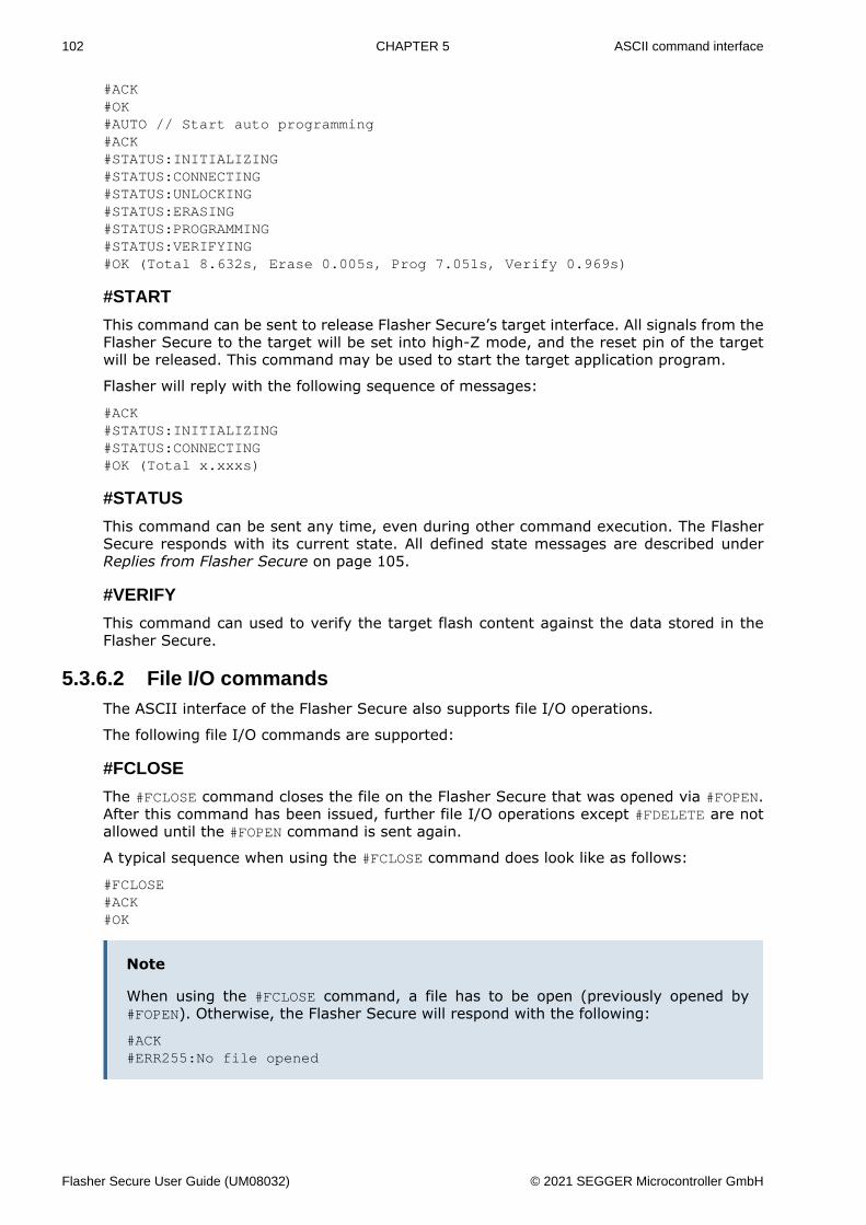
102 CHAPTER 5 ASCII command interface
#ACK#OK#AUTO // Start auto programming#ACK#STATUS:INITIALIZING#STATUS:CONNECTING#STATUS:UNLOCKING#STATUS:ERASING#STATUS:PROGRAMMING#STATUS:VERIFYING#OK (Total 8.632s, Erase 0.005s, Prog 7.051s, Verify 0.969s)
#START
This command can be sent to release Flasher Secure’s target interface. All signals from theFlasher Secure to the target will be set into high-Z mode, and the reset pin of the targetwill be released. This command may be used to start the target application program.
Flasher will reply with the following sequence of messages:
#ACK#STATUS:INITIALIZING#STATUS:CONNECTING#OK (Total x.xxxs)
#STATUS
This command can be sent any time, even during other command execution. The FlasherSecure responds with its current state. All defined state messages are described underReplies from Flasher Secure on page 105.
#VERIFY
This command can used to verify the target flash content against the data stored in theFlasher Secure.
5.3.6.2 File I/O commandsThe ASCII interface of the Flasher Secure also supports file I/O operations.
The following file I/O commands are supported:
#FCLOSE
The #FCLOSE command closes the file on the Flasher Secure that was opened via #FOPEN.After this command has been issued, further file I/O operations except #FDELETE are notallowed until the #FOPEN command is sent again.
A typical sequence when using the #FCLOSE command does look like as follows:
#FCLOSE#ACK#OK
Note
When using the #FCLOSE command, a file has to be open (previously opened by#FOPEN). Otherwise, the Flasher Secure will respond with the following:
#ACK#ERR255:No file opened
Flasher Secure User Guide (UM08032) © 2021 SEGGER Microcontroller GmbH
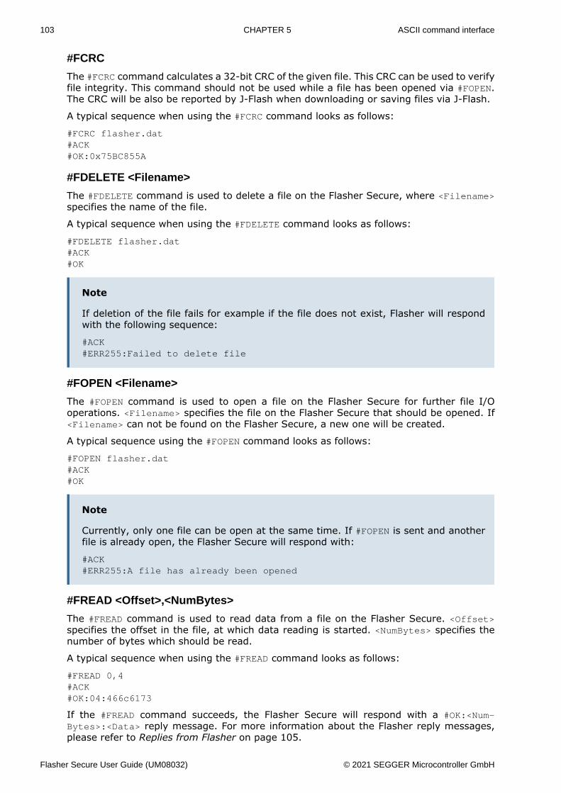
103 CHAPTER 5 ASCII command interface
#FCRC
The #FCRC command calculates a 32-bit CRC of the given file. This CRC can be used to verifyfile integrity. This command should not be used while a file has been opened via #FOPEN.The CRC will be also be reported by J-Flash when downloading or saving files via J-Flash.
A typical sequence when using the #FCRC command looks as follows:
#FCRC flasher.dat#ACK#OK:0x75BC855A
#FDELETE <Filename>
The #FDELETE command is used to delete a file on the Flasher Secure, where <Filename>specifies the name of the file.
A typical sequence when using the #FDELETE command looks as follows:
#FDELETE flasher.dat#ACK#OK
Note
If deletion of the file fails for example if the file does not exist, Flasher will respondwith the following sequence:
#ACK#ERR255:Failed to delete file
#FOPEN <Filename>
The #FOPEN command is used to open a file on the Flasher Secure for further file I/Ooperations. <Filename> specifies the file on the Flasher Secure that should be opened. If<Filename> can not be found on the Flasher Secure, a new one will be created.
A typical sequence using the #FOPEN command looks as follows:
#FOPEN flasher.dat#ACK#OK
Note
Currently, only one file can be open at the same time. If #FOPEN is sent and anotherfile is already open, the Flasher Secure will respond with:
#ACK#ERR255:A file has already been opened
#FREAD <Offset>,<NumBytes>
The #FREAD command is used to read data from a file on the Flasher Secure. <Offset>specifies the offset in the file, at which data reading is started. <NumBytes> specifies thenumber of bytes which should be read.
A typical sequence when using the #FREAD command looks as follows:
#FREAD 0,4#ACK#OK:04:466c6173
If the #FREAD command succeeds, the Flasher Secure will respond with a #OK:<Num-Bytes>:<Data> reply message. For more information about the Flasher reply messages,please refer to Replies from Flasher on page 105.
Flasher Secure User Guide (UM08032) © 2021 SEGGER Microcontroller GmbH
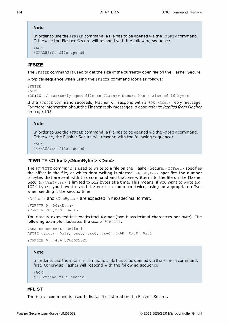
104 CHAPTER 5 ASCII command interface
Note
In order to use the #FREAD command, a file has to be opened via the #FOPEN command.Otherwise the Flasher Secure will respond with the following sequence:
#ACK#ERR255:No file opened
#FSIZE
The #FSIZE command is used to get the size of the currently open file on the Flasher Secure.
A typical sequence when using the #FSIZE command looks as follows:
#FSIZE#ACK#OK:10 // currently open file on Flasher Secure has a size of 16 bytes
If the #FSIZE command succeeds, Flasher will respond with a #OK:<Size> reply message.For more information about the Flasher reply messages, please refer to Replies from Flasheron page 105.
Note
In order to use the #FREAD command, a file has to be opened via the #FOPEN command.Otherwise, the Flasher Secure will respond with the following sequence:
#ACK#ERR255:No file opened
#FWRITE <Offset>,<NumBytes>:<Data>
The #FWRITE command is used to write to a file on the Flasher Secure. <Offset> specifiesthe offset in the file, at which data writing is started. <NumBytes> specifies the numberof bytes that are sent with this command and that are written into the file on the FlasherSecure. <NumBytes> is limited to 512 bytes at a time. This means, if you want to write e.g.1024 bytes, you have to send the #FWRITE command twice, using an appropriate offsetwhen sending it the second time.
<Offset> and <NumBytes> are expected in hexadecimal format.
#FWRITE 0,200:<Data>#FWRITE 200,200:<Data>
The data is expected in hexadecimal format (two hexadecimal characters per byte). Thefollowing example illustrates the use of #FWRITE:
Data to be sent: Hello !ASCII values: 0x48, 0x65, 0x6C, 0x6C, 0x6F, 0x20, 0x21
#FWRITE 0,7:48656C6C6F2021
Note
In order to use the #FWRITE command a file has to be opened via the #FOPEN command,first. Otherwise Flasher will respond with the following sequence:
#ACK#ERR255:No file opened
#FLIST
The #LIST command is used to list all files stored on the Flasher Secure.
Flasher Secure User Guide (UM08032) © 2021 SEGGER Microcontroller GmbH
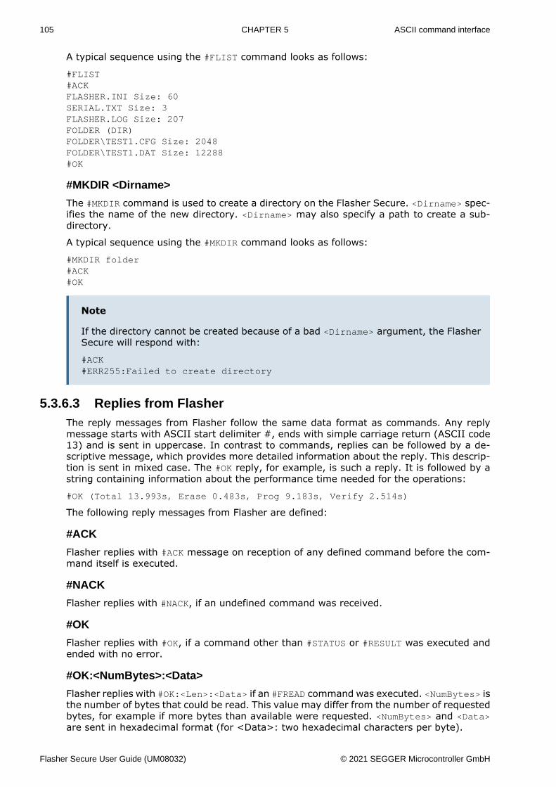
105 CHAPTER 5 ASCII command interface
A typical sequence using the #FLIST command looks as follows:
#FLIST#ACKFLASHER.INI Size: 60SERIAL.TXT Size: 3FLASHER.LOG Size: 207FOLDER (DIR)FOLDER\TEST1.CFG Size: 2048FOLDER\TEST1.DAT Size: 12288#OK
#MKDIR <Dirname>
The #MKDIR command is used to create a directory on the Flasher Secure. <Dirname> spec-ifies the name of the new directory. <Dirname> may also specify a path to create a sub-directory.
A typical sequence using the #MKDIR command looks as follows:
#MKDIR folder#ACK#OK
Note
If the directory cannot be created because of a bad <Dirname> argument, the FlasherSecure will respond with:
#ACK#ERR255:Failed to create directory
5.3.6.3 Replies from FlasherThe reply messages from Flasher follow the same data format as commands. Any replymessage starts with ASCII start delimiter #, ends with simple carriage return (ASCII code13) and is sent in uppercase. In contrast to commands, replies can be followed by a de-scriptive message, which provides more detailed information about the reply. This descrip-tion is sent in mixed case. The #OK reply, for example, is such a reply. It is followed by astring containing information about the performance time needed for the operations:
#OK (Total 13.993s, Erase 0.483s, Prog 9.183s, Verify 2.514s)
The following reply messages from Flasher are defined:
#ACK
Flasher replies with #ACK message on reception of any defined command before the com-mand itself is executed.
#NACK
Flasher replies with #NACK, if an undefined command was received.
#OK
Flasher replies with #OK, if a command other than #STATUS or #RESULT was executed andended with no error.
#OK:<NumBytes>:<Data>
Flasher replies with #OK:<Len>:<Data> if an #FREAD command was executed. <NumBytes> isthe number of bytes that could be read. This value may differ from the number of requestedbytes, for example if more bytes than available were requested. <NumBytes> and <Data>are sent in hexadecimal format (for <Data>: two hexadecimal characters per byte).
Flasher Secure User Guide (UM08032) © 2021 SEGGER Microcontroller GmbH
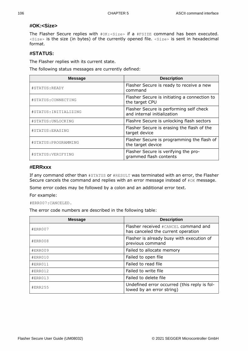
106 CHAPTER 5 ASCII command interface
#OK:<Size>
The Flasher Secure replies with #OK:<Size> if a #FSIZE command has been executed.<Size> is the size (in bytes) of the currently opened file. <Size> is sent in hexadecimalformat.
#STATUS:
The Flasher replies with its current state.
The following status messages are currently defined:
Message Description
#STATUS:READYFlasher Secure is ready to receive a newcommand
#STATUS:CONNECTINGFlasher Secure is initiating a connection tothe target CPU
#STATUS:INITIALIZINGFlasher Secure is performing self checkand internal initialization
#STATUS:UNLOCKING Flashre Secure is unlocking flash sectors
#STATUS:ERASINGFlasher Secure is erasing the flash of thetarget device
#STATUS:PROGRAMMINGFlasher Secure is programming the flash ofthe target device
#STATUS:VERIFYINGFlasher Secure is verifying the pro-grammed flash contents
#ERRxxx
If any command other than #STATUS or #RESULT was terminated with an error, the FlasherSecure cancels the command and replies with an error message instead of #OK message.
Some error codes may be followed by a colon and an additional error text.
For example:
#ERR007:CANCELED.
The error code numbers are described in the following table:
Message Description
#ERR007Flasher received #CANCEL command andhas canceled the current operation
#ERR008Flasher is already busy with execution ofprevious command
#ERR009 Failed to allocate memory#ERR010 Failed to open file#ERR011 Failed to read file#ERR012 Failed to write file#ERR013 Failed to delete file
#ERR255Undefined error occurred (this reply is fol-lowed by an error string)
Flasher Secure User Guide (UM08032) © 2021 SEGGER Microcontroller GmbH
Chapter 6 Device Firmware
The firmware of the target device needs to implement the emSecure software package.The security features of the emSecure software package are used to verify if the flasheddevice signature is valid or not.
Flasher Secure User Guide (UM08032) © 2021 SEGGER Microcontroller GmbH
108 CHAPTER 6 emSecure Package
6.1 emSecure PackageThe emSecure software package comes with its own detailed documentation. Therefore,only the main topics are described in this manual. For details about the emSecure library,please take a closer look at the UM12002 emSecure RSA or UM 12004 emSecure ECDSAmanuals.
Flasher Secure User Guide (UM08032) © 2021 SEGGER Microcontroller GmbH

109 CHAPTER 6 Implementing emSecure
6.2 Implementing emSecureThe emSecure software package is part of the Flasher Secure shipment.
6.2.1 Package content:emSecure is provided in source code and contains everything needed. The following tableshows the content of the emSecure package:
Files Description
Application Sample applications for bare metal and embOSConfig Configuration header filesDoc emSecure documentationCRYPTO Shared cryptographic library source codeSECURE emSecure implementation codeSEGGER SEGGER software component source code used in emSecureSample/Config Example emSecure configurationSample/Keys Example emSecure key pairsWindows Supporting applications in binary and source form
6.2.2 Include directoriesPlease make sure that the include path contains the following directories (the order ofinclusion is of no importance):• Config• CRYPTO\Inc• SECURE\Inc• SEGGER• SETUP
Add the source files from the following directories to your project:• CRYPTO• SECURE• SEGGER• SETUP\Crypto
Note
Always make sure that you have only one version of each file!
It is frequently a major problem when updating to a new version of emSecure-RSA if youhave old files included and therefore mix different versions. If you keep emSecure-RSA inthe directories as suggested (and only in these), this type of problem cannot occur. Whenupdating to a newer version, you should be able to keep your configuration files and leavethem unchanged. For safety reasons, we recommend backing up (or at least renaming) theSECURE directories before updating.
Flasher Secure User Guide (UM08032) © 2021 SEGGER Microcontroller GmbH
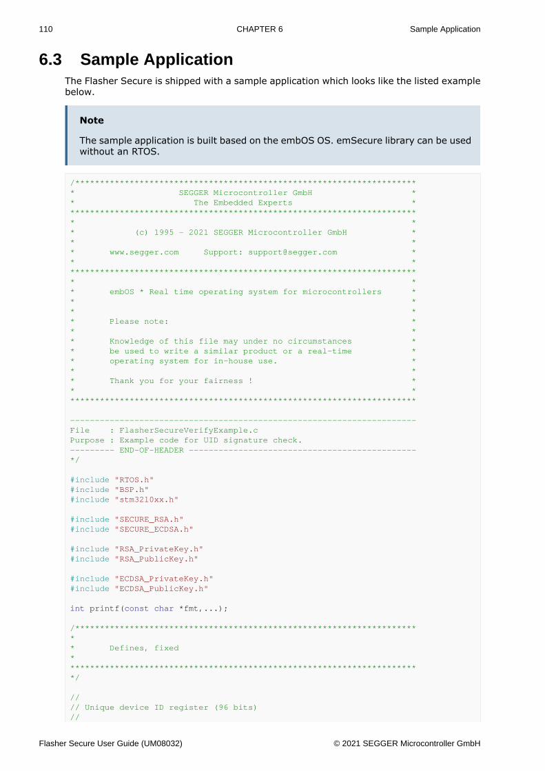
110 CHAPTER 6 Sample Application
6.3 Sample ApplicationThe Flasher Secure is shipped with a sample application which looks like the listed examplebelow.
Note
The sample application is built based on the embOS OS. emSecure library can be usedwithout an RTOS.
/********************************************************************** SEGGER Microcontroller GmbH ** The Embedded Experts ************************************************************************ ** (c) 1995 - 2021 SEGGER Microcontroller GmbH ** ** www.segger.com Support: [email protected] ** ************************************************************************ ** embOS * Real time operating system for microcontrollers ** ** ** Please note: ** ** Knowledge of this file may under no circumstances ** be used to write a similar product or a real-time ** operating system for in-house use. ** ** Thank you for your fairness ! ** ***********************************************************************
----------------------------------------------------------------------File : FlasherSecureVerifyExample.cPurpose : Example code for UID signature check.--------- END-OF-HEADER ----------------------------------------------*/
#include "RTOS.h"#include "BSP.h"#include "stm32l0xx.h"
#include "SECURE_RSA.h"#include "SECURE_ECDSA.h"
#include "RSA_PrivateKey.h"#include "RSA_PublicKey.h"
#include "ECDSA_PrivateKey.h"#include "ECDSA_PublicKey.h"
int printf(const char *fmt,...);
/*********************************************************************** Defines, fixed************************************************************************/
//// Unique device ID register (96 bits)//
Flasher Secure User Guide (UM08032) © 2021 SEGGER Microcontroller GmbH
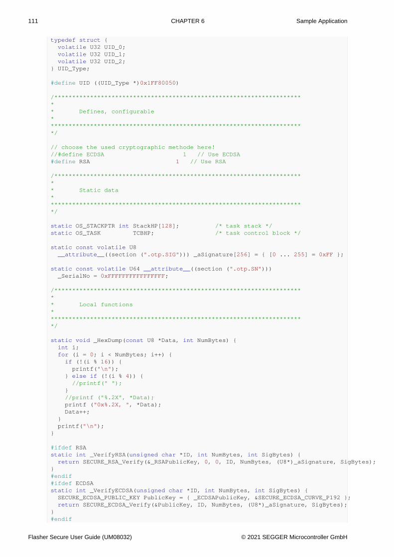
111 CHAPTER 6 Sample Application
typedef struct { volatile U32 UID_0; volatile U32 UID_1; volatile U32 UID_2;} UID_Type;
#define UID ((UID_Type *)0x1FF80050)
/*********************************************************************** Defines, configurable************************************************************************/
// choose the used cryptographic methode here!//#define ECDSA 1 // Use ECDSA#define RSA 1 // Use RSA
/*********************************************************************** Static data************************************************************************/
static OS_STACKPTR int StackHP[128]; /* task stack */static OS_TASK TCBHP; /* task control block */
static const volatile U8 __attribute__((section (".otp.SIG"))) _aSignature[256] = { [0 ... 255] = 0xFF };
static const volatile U64 __attribute__((section (".otp.SN"))) _SerialNo = 0xFFFFFFFFFFFFFFFF;
/*********************************************************************** Local functions************************************************************************/
static void _HexDump(const U8 *Data, int NumBytes) { int i; for (i = 0; i < NumBytes; i++) { if (!(i % 16)) { printf("\n"); } else if (!(i % 4)) { //printf(" "); } //printf ("%.2X", *Data); printf ("0x%.2X, ", *Data); Data++; } printf("\n");}
#ifdef RSAstatic int _VerifyRSA(unsigned char *ID, int NumBytes, int SigBytes) { return SECURE_RSA_Verify(&_RSAPublicKey, 0, 0, ID, NumBytes, (U8*)_aSignature, SigBytes);}#endif#ifdef ECDSAstatic int _VerifyECDSA(unsigned char *ID, int NumBytes, int SigBytes) { SECURE_ECDSA_PUBLIC_KEY PublicKey = { _ECDSAPublicKey, &SECURE_ECDSA_CURVE_P192 }; return SECURE_ECDSA_Verify(&PublicKey, ID, NumBytes, (U8*)_aSignature, SigBytes);}#endif
Flasher Secure User Guide (UM08032) © 2021 SEGGER Microcontroller GmbH
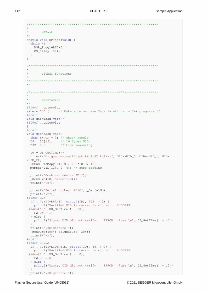
112 CHAPTER 6 Sample Application
/*********************************************************************** HPTask*/static void HPTask(void) { while (1) { BSP_ToggleLED(0); OS_Delay (50); }}
/*********************************************************************** Global functions************************************************************************/
/*********************************************************************** MainTask()*/#ifdef __cplusplusextern "C" { /* Make sure we have C-declarations in C++ programs */#endifvoid MainTask(void);#ifdef __cplusplus}#endifvoid MainTask(void) { char FW_OK = 0; // check result U8 ID[16]; // 16 Bytes UID U32 t0; // time measuring
t0 = OS_GetTime(); printf("Unique device ID:\n%.8X %.8X %.8X\n", UID->UID_0, UID->UID_1, UID->UID_2); SEGGER_memcpy(&ID[0], (U8*)UID, 12); memset(&ID[12], 0, 4); // zero padding
printf("Combined device ID:"); _HexDump(ID, sizeof(ID)); printf("\n");
printf("Serial number: %lld", _SerialNo); printf("\n");#ifdef RSA if (_VerifyRSA(ID, sizeof(ID), 256) > 0) { printf("Verified UID is correctly signed... SUCCESS! (%dms)\n", OS_GetTime() - t0); FW_OK = 1; } else { printf("Signed UID did not verify... ERROR! (%dms)\n", OS_GetTime() - t0); } printf("\nSignature:"); _HexDump((U8*)_aSignature, 256); printf("\n");#endif#ifdef ECDSA if (_VerifyECDSA(ID, sizeof(ID), 48) > 0) { printf("Verified UID is correctly signed... SUCCESS! (%dms)\n", OS_GetTime() - t0); FW_OK = 2; } else { printf("Signed UID did not verify... ERROR! (%dms)\n", OS_GetTime() - t0); } printf("\nSignature:");
Flasher Secure User Guide (UM08032) © 2021 SEGGER Microcontroller GmbH
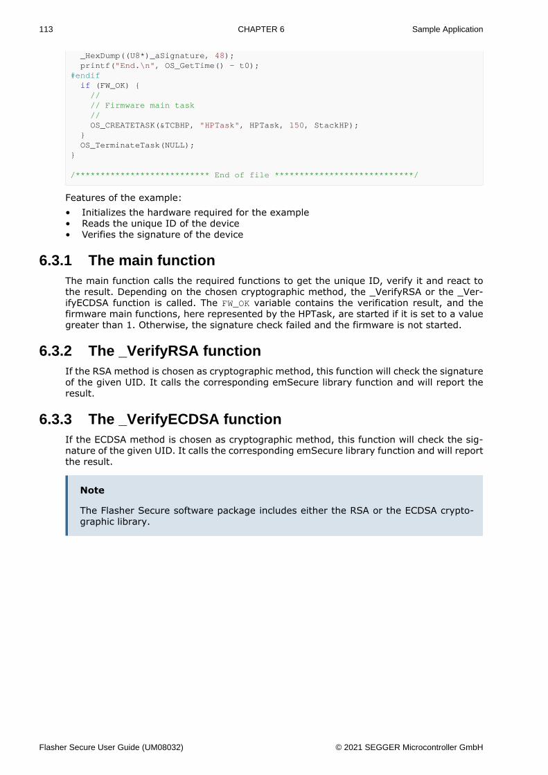
113 CHAPTER 6 Sample Application
_HexDump((U8*)_aSignature, 48); printf("End.\n", OS_GetTime() - t0);#endif if (FW_OK) { // // Firmware main task // OS_CREATETASK(&TCBHP, "HPTask", HPTask, 150, StackHP); } OS_TerminateTask(NULL);}
/*************************** End of file ****************************/
Features of the example:• Initializes the hardware required for the example• Reads the unique ID of the device• Verifies the signature of the device
6.3.1 The main functionThe main function calls the required functions to get the unique ID, verify it and react tothe result. Depending on the chosen cryptographic method, the _VerifyRSA or the _Ver-ifyECDSA function is called. The FW_OK variable contains the verification result, and thefirmware main functions, here represented by the HPTask, are started if it is set to a valuegreater than 1. Otherwise, the signature check failed and the firmware is not started.
6.3.2 The _VerifyRSA functionIf the RSA method is chosen as cryptographic method, this function will check the signatureof the given UID. It calls the corresponding emSecure library function and will report theresult.
6.3.3 The _VerifyECDSA functionIf the ECDSA method is chosen as cryptographic method, this function will check the sig-nature of the given UID. It calls the corresponding emSecure library function and will reportthe result.
Note
The Flasher Secure software package includes either the RSA or the ECDSA crypto-graphic library.
Flasher Secure User Guide (UM08032) © 2021 SEGGER Microcontroller GmbH
Chapter 7 Hardware and Adapters
This chapter gives an overview about Flasher Secure specific hardware details, such as thepinouts and available adapters.
Flasher Secure User Guide (UM08032) © 2021 SEGGER Microcontroller GmbH

115 CHAPTER 7 ARM 20-pin JTAG/SWD Connector
7.1 ARM 20-pin JTAG/SWD ConnectorFlasher Secure has a JTAG connector compatible with ARM JTAG standard. The JTAG con-nector is a 20 way Insulation Displacement Connector (IDC) keyed box header (2.54mmmale) that mates with IDC sockets mounted on a ribbon cable.
7.1.1 Pinout JTAG
The following table lists the JTAG pinout.
PIN SIGNAL TYPE Description
1 VTref Input
This is the target reference voltage. It is used to check if thetarget has power, to create the logic-level reference for theinput comparators and to control the output logic levels tothe target. It is normally fed from Vdd of the target boardand must not have a series resistor.
2 Vsupply NCThis pin is not connected to Flasher Secure. It is reserved forcompatibility with other equipment. Connect to Vdd or leaveopen in target system.
3 nTRST Output
JTAG Reset. Output from Flasher Secure to the Reset signalof the target JTAG port. Typically connected to nTRST of thetarget CPU. This pin is normally pulled HIGH on the target toavoid unintentional resets when there is no connection.
5 TDI OutputJTAG data input of target CPU. It is recommended that thispin is pulled to a defined state on the target board. Typicallyconnected to TDI of target CPU.
7 TMS Output JTAG mode set input of target CPU. This pin should be pulledup on the target. Typically connected to TMS of target CPU.
9 TCK OutputJTAG clock signal to target CPU. It is recommended that thispin is pulled to a defined state of the target board. Typicallyconnected to TCK of target CPU.
11 RTCK Input
Return test clock signal from the target. Some targets mustsynchronize the JTAG inputs to internal clocks. To assistin meeting this requirement, you can use a returned, andretimed, TCK to dynamically control the TCK rate. Flash-er Secure supports adaptive clocking, which waits for TCKchanges to be echoed correctly before making furtherchanges. Connect to RTCK if available, otherwise to GND.
13 TDO Input JTAG data output from target CPU. Typically connected toTDO of target CPU.
15 RESET I/OTarget CPU reset signal. Typically connected to the RESETpin of the target CPU, which is typically called “nRST”,“nRESET” or “RESET”.
Flasher Secure User Guide (UM08032) © 2021 SEGGER Microcontroller GmbH
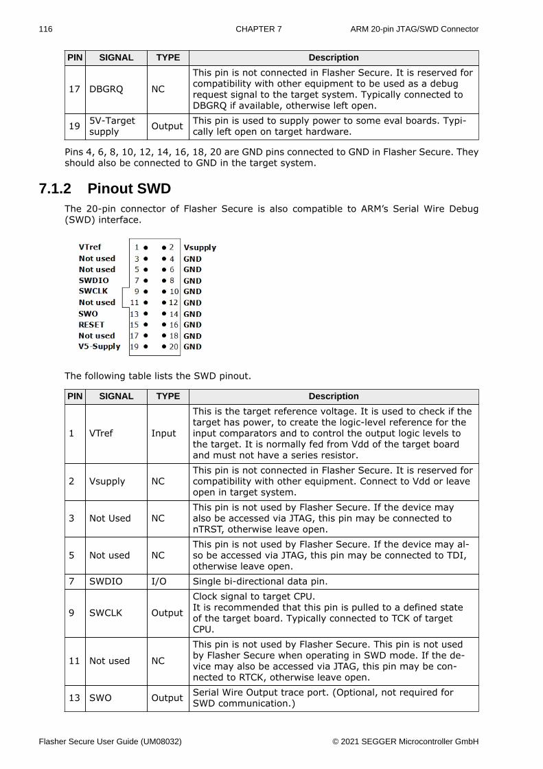
116 CHAPTER 7 ARM 20-pin JTAG/SWD Connector
PIN SIGNAL TYPE Description
17 DBGRQ NC
This pin is not connected in Flasher Secure. It is reserved forcompatibility with other equipment to be used as a debugrequest signal to the target system. Typically connected toDBGRQ if available, otherwise left open.
19 5V-Targetsupply Output This pin is used to supply power to some eval boards. Typi-
cally left open on target hardware.
Pins 4, 6, 8, 10, 12, 14, 16, 18, 20 are GND pins connected to GND in Flasher Secure. Theyshould also be connected to GND in the target system.
7.1.2 Pinout SWDThe 20-pin connector of Flasher Secure is also compatible to ARM’s Serial Wire Debug(SWD) interface.
The following table lists the SWD pinout.
PIN SIGNAL TYPE Description
1 VTref Input
This is the target reference voltage. It is used to check if thetarget has power, to create the logic-level reference for theinput comparators and to control the output logic levels tothe target. It is normally fed from Vdd of the target boardand must not have a series resistor.
2 Vsupply NCThis pin is not connected in Flasher Secure. It is reserved forcompatibility with other equipment. Connect to Vdd or leaveopen in target system.
3 Not Used NCThis pin is not used by Flasher Secure. If the device mayalso be accessed via JTAG, this pin may be connected tonTRST, otherwise leave open.
5 Not used NCThis pin is not used by Flasher Secure. If the device may al-so be accessed via JTAG, this pin may be connected to TDI,otherwise leave open.
7 SWDIO I/O Single bi-directional data pin.
9 SWCLK Output
Clock signal to target CPU.It is recommended that this pin is pulled to a defined stateof the target board. Typically connected to TCK of targetCPU.
11 Not used NC
This pin is not used by Flasher Secure. This pin is not usedby Flasher Secure when operating in SWD mode. If the de-vice may also be accessed via JTAG, this pin may be con-nected to RTCK, otherwise leave open.
13 SWO Output Serial Wire Output trace port. (Optional, not required forSWD communication.)
Flasher Secure User Guide (UM08032) © 2021 SEGGER Microcontroller GmbH
117 CHAPTER 7 ARM 20-pin JTAG/SWD Connector
PIN SIGNAL TYPE Description
15 RESET I/OTarget CPU reset signal. Typically connected to the RESETpin of the target CPU, which is typically called “nRST”,“nRESET” or “RESET”.
17 Not used NC This pin is not connected in Flasher Secure.
19 5V-Targetsupply Output
This pin is used to supply power to some eval boards. Not allJ-Links supply power on this pin, only the KS (Kickstart) ver-sions. Typically left open on target hardware.
Pins 4, 6, 8, 10, 12, 14, 16, 18, 20 are GND pins connected to GND in Flasher Secure. Theyshould also be connected to GND in the target system.
7.1.3 Target power supplyPin 19 of the connector can be used to supply power to the target hardware. Supply volt-age is 5V, max. current is 400mA. The output current is monitored and protected againstoverload and short-circuit.
Power can be controlled via the J-Link commander. The following commands are availableto control power:
Command Explanation
power on Switch target power onpower off Switch target power offpower on perm Set target power supply default to “on”power off perm Set target power supply default to “off”
Flasher Secure User Guide (UM08032) © 2021 SEGGER Microcontroller GmbH

118 CHAPTER 7 Flasher RX 14-pin connector
7.2 Flasher RX 14-pin connectorFlasher Secure itself has a 20-pin JTAG connector mounted but an optional J-Link 14-pin RXadapter is available. This adapter enables Flasher Secure to optionally power the connectedtarget hardware. On the adapter there is a jumper which allows selection between 3.3Vand 5V supply target voltage supply. The target is supplied via the VTref connection whenthe supply option is jumpered.
The following table lists the J-Link RX 14-pin JTAG pinout.
Pin Signal Type Description
1 TCK OutputJTAG clock signal to target CPU. It is recommended that thispin is pulled to a defined state on the target board. Typicallyconnected to TCK on target CPU.
3 TRSTn Output
JTAG Reset. Output from Flasher Secure to the Reset signalof the target JTAG port. Typically connected to nTRST of thetarget CPU. This pin is normally pulled HIGH on the target toavoid unintentional resets when there is no connection.
4 EMLE Output
Pin for the on-chip emulator enable signal. When the on-chipemulator is used, this pin should be driven high. When notused, it should be driven low. Pulled HIGH to VTref via 1kpull-up resistor on 14-pin adapter.
5 TDO Input JTAG data output from target CPU. Typically connected toTDO on target CPU.
6 — NC This pin is not connected to Flasher Secure.7 — NC This pin is not connected to Flasher Secure.
8 VTref Input
This is the target reference voltage. It is used to check if thetarget has power, to create the logic-level reference for theinput comparators and to control the output logic levels tothe target. It is normally fed from Vdd of the target boardand must not have a series resistor.
9 TMS Output JTAG mode set input of target CPU. This pin should be pulledup on the target. Typically connected to TMS on target CPU.
10 — NC This pin is not connected to Flasher Secure.
11 TDI OutputJTAG data input of target CPU. It is recommended that thispin is pulled to a defined state on the target board. Typicallyconnected to TDI on target CPU.
13 nRES I/OTarget CPU reset signal. Typically connected to the RESETpin of the target CPU, which is typically called “nRST”,“nRESET” or “RESET”.
• All pins marked NC are not connected to Flasher Secure. Any signal can be applied here;Flasher Secure will simply ignore such a signal.
• Pins 2, 12, 14 are GND pins connected to GND in Flasher Secure. They should also beconnected to GND in the target system.
Flasher Secure User Guide (UM08032) © 2021 SEGGER Microcontroller GmbH
119 CHAPTER 7 Flasher RX 14-pin connector
7.2.1 Target power supplyPin 8 of the 14-pin connector can be used to supply power to the target hardware. Supplyvoltage is 3.3V / 5V, max. current is 400mA. The output current is monitored and protectedagainst overload and short-circuit. Power can be controlled via the J-Link commander. Thefollowing commands are available to control power:
Command Explanation
power on Switch target power onpower off Switch target power offpower on perm Set target power supply default to “on”power off perm Set target power supply default to “off”
Flasher Secure User Guide (UM08032) © 2021 SEGGER Microcontroller GmbH
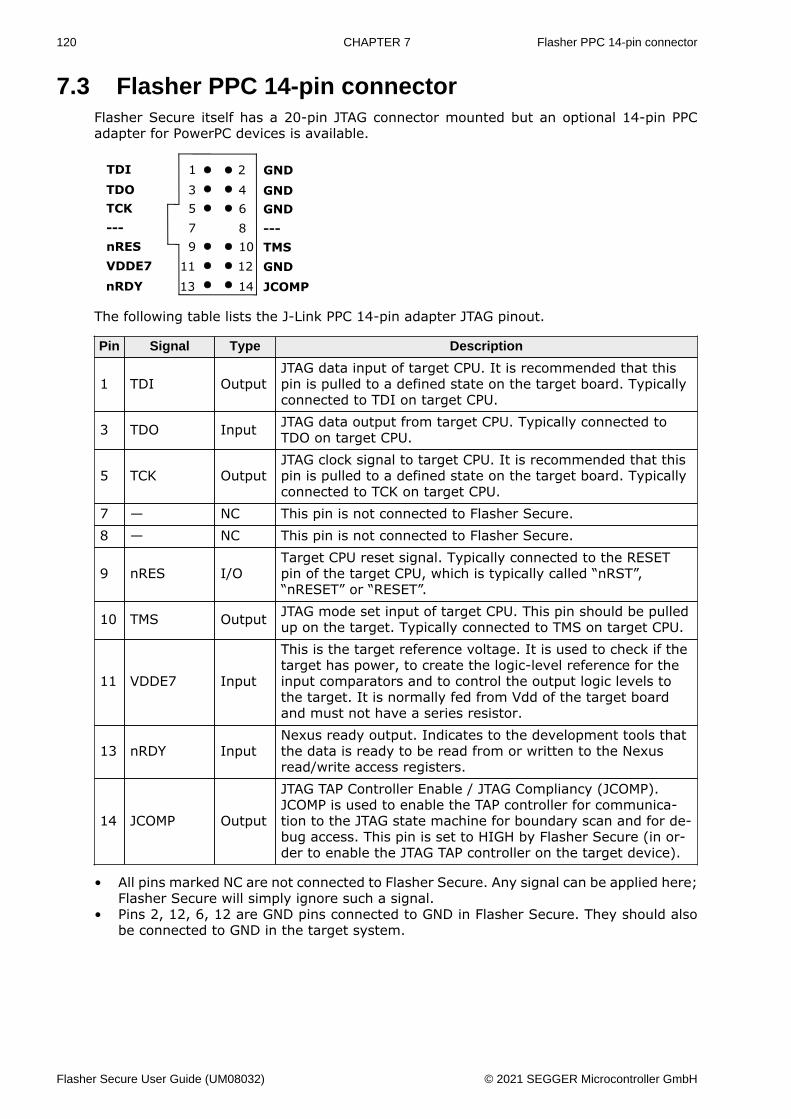
120 CHAPTER 7 Flasher PPC 14-pin connector
7.3 Flasher PPC 14-pin connectorFlasher Secure itself has a 20-pin JTAG connector mounted but an optional 14-pin PPCadapter for PowerPC devices is available.
The following table lists the J-Link PPC 14-pin adapter JTAG pinout.
Pin Signal Type Description
1 TDI OutputJTAG data input of target CPU. It is recommended that thispin is pulled to a defined state on the target board. Typicallyconnected to TDI on target CPU.
3 TDO Input JTAG data output from target CPU. Typically connected toTDO on target CPU.
5 TCK OutputJTAG clock signal to target CPU. It is recommended that thispin is pulled to a defined state on the target board. Typicallyconnected to TCK on target CPU.
7 — NC This pin is not connected to Flasher Secure.8 — NC This pin is not connected to Flasher Secure.
9 nRES I/OTarget CPU reset signal. Typically connected to the RESETpin of the target CPU, which is typically called “nRST”,“nRESET” or “RESET”.
10 TMS Output JTAG mode set input of target CPU. This pin should be pulledup on the target. Typically connected to TMS on target CPU.
11 VDDE7 Input
This is the target reference voltage. It is used to check if thetarget has power, to create the logic-level reference for theinput comparators and to control the output logic levels tothe target. It is normally fed from Vdd of the target boardand must not have a series resistor.
13 nRDY InputNexus ready output. Indicates to the development tools thatthe data is ready to be read from or written to the Nexusread/write access registers.
14 JCOMP Output
JTAG TAP Controller Enable / JTAG Compliancy (JCOMP).JCOMP is used to enable the TAP controller for communica-tion to the JTAG state machine for boundary scan and for de-bug access. This pin is set to HIGH by Flasher Secure (in or-der to enable the JTAG TAP controller on the target device).
• All pins marked NC are not connected to Flasher Secure. Any signal can be applied here;Flasher Secure will simply ignore such a signal.
• Pins 2, 12, 6, 12 are GND pins connected to GND in Flasher Secure. They should alsobe connected to GND in the target system.
Flasher Secure User Guide (UM08032) © 2021 SEGGER Microcontroller GmbH
121 CHAPTER 7 Target board design
7.4 Target board designWe strongly advise following the recommendations given by the chip manufacturer. Theserecommendations are normally in line with the recommendations. Please refer to the theappropriate tables depending on the core:• Pinout JTAG on page 115• Pinout SWD on page 116• J-Link RX 14-Pin Adapter, J-Link RX FINE 14-Pin Adapter on page 118• J-Link PPC 14-Pin Adapter on page 120
In case of doubt you should follow the recommendations given by the semiconductor man-ufacturer.
7.4.1 Pull-up/pull-down resistorsUnless otherwise specified by developer’s manual, pull-ups/pull-downs are recommendedto be between 2.2 kOhms and 47 kOhms.
7.4.2 RESET, nTRSTThe debug logic is reset independently from the CPU core with nTRST. For the core tooperate correctly it is essential that both signals are asserted after power-up.
The advantage of having separate connection to the two reset signals is that it allows thedeveloper performing software debug to setup breakpoints, which are retained by the debuglogic even when the core is reset. (For example, at the reset vector address, to allow thecode to be single-stepped as soon as it comes out of reset). This can be particularly usefulwhen first trying to bring up a board with a new ASIC.
Flasher Secure User Guide (UM08032) © 2021 SEGGER Microcontroller GmbH

122 CHAPTER 7 Adapters
7.5 Adapters
7.5.1 JTAG IsolatorThe JTAG Isolator can be connected between Flasher and JTAG adapter, to provide electricalisolation. This is essential when the development tools are not connected to the sameground as the application. For more information about the JTAG Isolator, please refer to J-Link JTAG Isolator User Manual (UM08010) which can be downloaded from our website.
7.5.1.1 PinoutThe following table shows the target-side pinout of the J-Link JTAG Isolator.
Pin Signal Type Description
1 VCC Output The target side of the isolator draws power over this pin.2 VCC Output The target side of the isolator draws power over this pin.
3 nTRST Output
JTAG Reset. Output from Flasher to the Reset signal of thetarget JTAG port. Typically connected to nTRST of the targetCPU. This pin is normally pulled HIGH on the target to avoidunintentional resets when there is no connection.
5 TDI OutputJTAG data input of target CPU. It is recommended that thispin is pulled to a defined state on the target board. Typicallyconnected to TDI of target CPU.
7 TMS Output JTAG mode set input of target CPU. This pin should be pulledup on the target. Typically connected to TMS of target CPU.
9 TCK OutputJTAG clock signal to target CPU. It is recommended that thispin is pulled to a defined state of the target board. Typicallyconnected to TCK of target CPU.
11 RTCK Input
Return test clock signal from the target. Some targets mustsynchronize the JTAG inputs to internal clocks. To assist inmeeting this requirement, you can use a returned, and re-timed, TCK to dynamically control the TCK rate.
13 TDO Input JTAG data output from target CPU. Typically connected toTDO of target CPU.
15 RESET I/OTarget CPU reset signal. Typically connected to the RESETpin of the target CPU, which is typically called “nRST”,“nRESET” or “RESET”.
17 N/C N/C This pin is not connected on the target side of the isolator.19 N/C N/C This pin is not connected on the target side of the isolator.
Flasher Secure User Guide (UM08032) © 2021 SEGGER Microcontroller GmbH
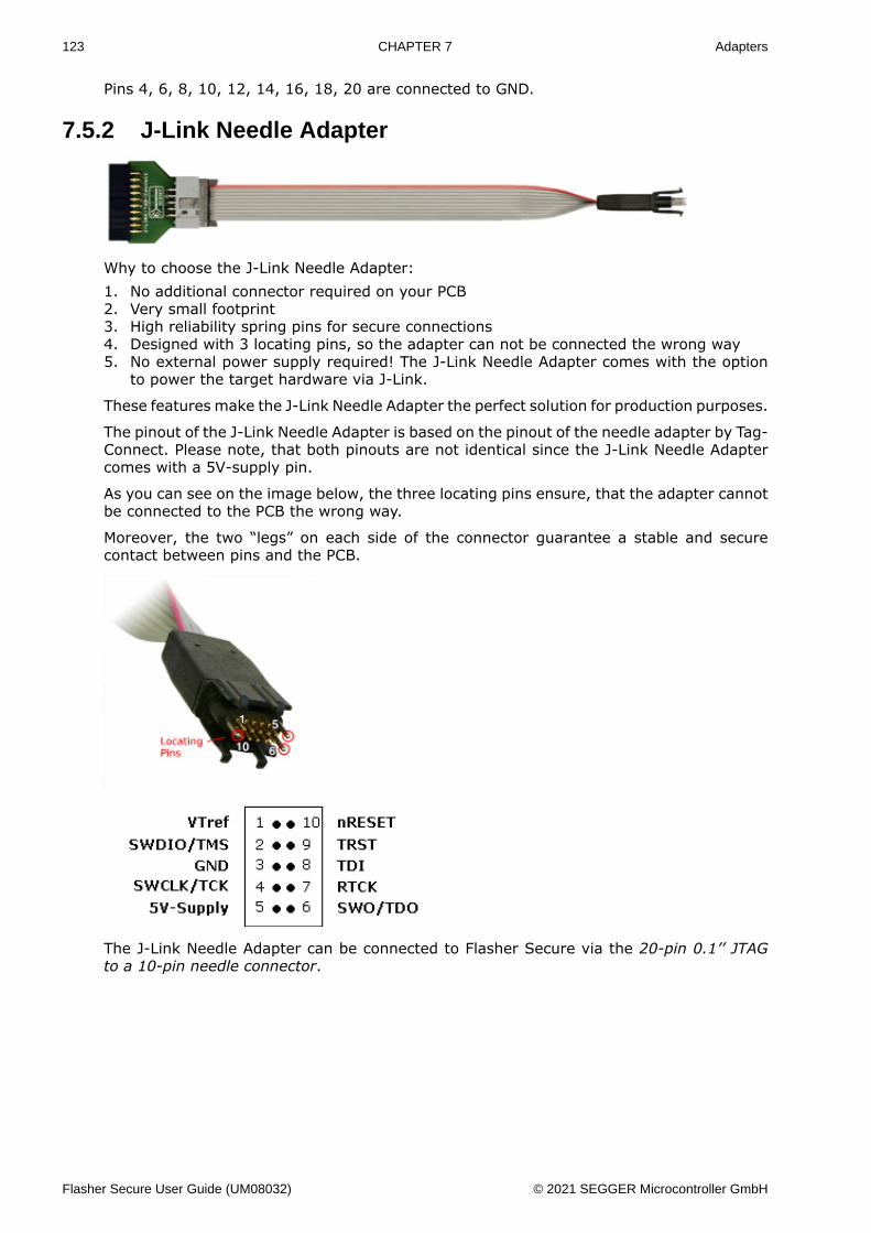
123 CHAPTER 7 Adapters
Pins 4, 6, 8, 10, 12, 14, 16, 18, 20 are connected to GND.
7.5.2 J-Link Needle Adapter
Why to choose the J-Link Needle Adapter:1. No additional connector required on your PCB2. Very small footprint3. High reliability spring pins for secure connections4. Designed with 3 locating pins, so the adapter can not be connected the wrong way5. No external power supply required! The J-Link Needle Adapter comes with the option
to power the target hardware via J-Link.
These features make the J-Link Needle Adapter the perfect solution for production purposes.
The pinout of the J-Link Needle Adapter is based on the pinout of the needle adapter by Tag-Connect. Please note, that both pinouts are not identical since the J-Link Needle Adaptercomes with a 5V-supply pin.
As you can see on the image below, the three locating pins ensure, that the adapter cannotbe connected to the PCB the wrong way.
Moreover, the two “legs” on each side of the connector guarantee a stable and securecontact between pins and the PCB.
The J-Link Needle Adapter can be connected to Flasher Secure via the 20-pin 0.1’’ JTAGto a 10-pin needle connector.
Flasher Secure User Guide (UM08032) © 2021 SEGGER Microcontroller GmbH
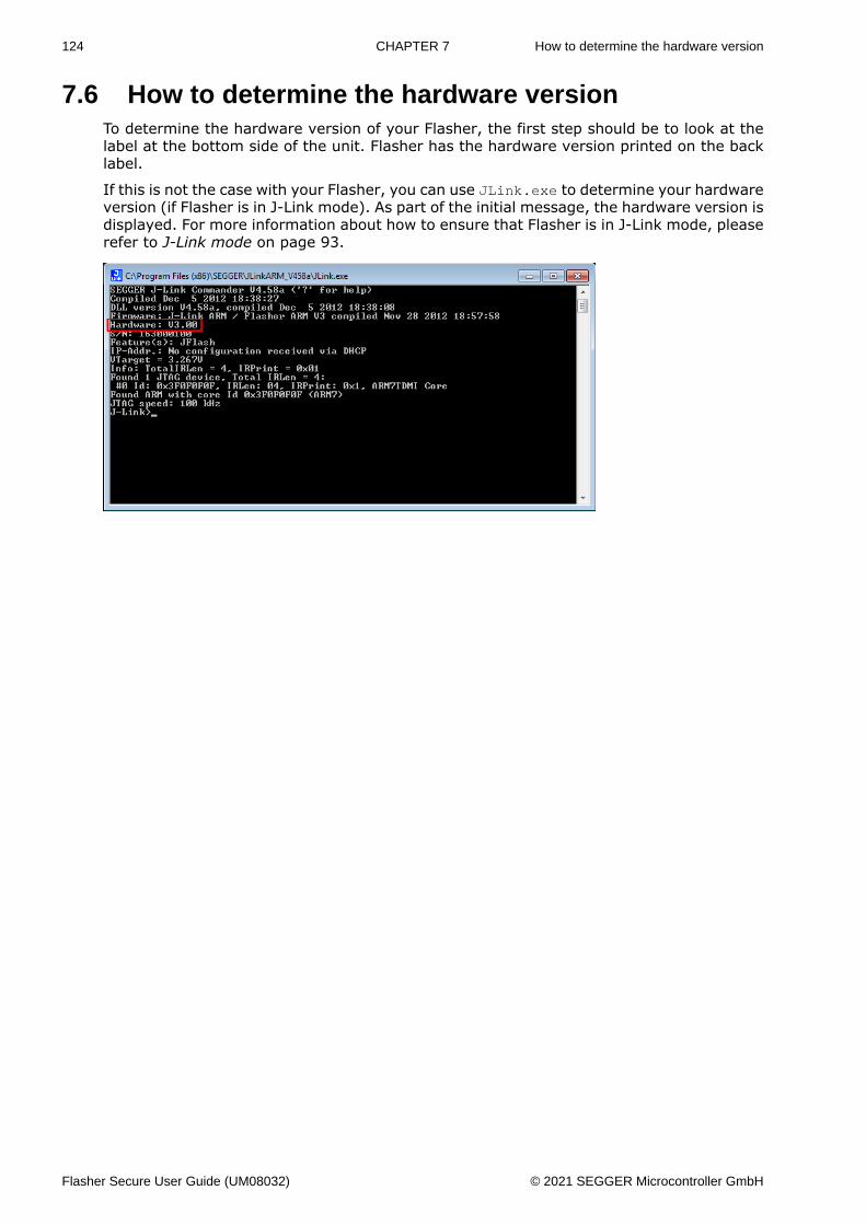
124 CHAPTER 7 How to determine the hardware version
7.6 How to determine the hardware versionTo determine the hardware version of your Flasher, the first step should be to look at thelabel at the bottom side of the unit. Flasher has the hardware version printed on the backlabel.
If this is not the case with your Flasher, you can use JLink.exe to determine your hardwareversion (if Flasher is in J-Link mode). As part of the initial message, the hardware version isdisplayed. For more information about how to ensure that Flasher is in J-Link mode, pleaserefer to J-Link mode on page 93.
Flasher Secure User Guide (UM08032) © 2021 SEGGER Microcontroller GmbH
Chapter 8 Support
This chapter contains troubleshooting tips together with solutions for common problemswhich might occur when using Flasher Secure. There are several steps you can take beforecontacting support. Performing these steps can solve many problems and often eliminatesthe need for assistance. This chapter also contains a collection of frequently asked questions(FAQs) with answers.
Flasher Secure User Guide (UM08032) © 2021 SEGGER Microcontroller GmbH
126 CHAPTER 8 Contacting support
8.1 Contacting supportBefore contacting support, make sure you tried to solve your problem by trying your FlasherSecure with another PC and if possible with another target system to see if it works there.If the device functions correctly, the USB setup on the original machine or your targethardware is the source of the problem, not Flasher Secure.
If you need to contact support, send the following information [email protected]• A detailed description of the problem• the serial number• Information about your target hardware (processor, board, etc.).• FLASHER.CFG, FLASHER.DAT, FLASHER.LOG, SERIAL.TXT file from the Flasher. To get
these files, Flasher has to be in MSD mode. For more information about how to boot theunit in MSD mode, please refer to MSD mode on page 86. In case of a Flasher Securesome files need to be shared from the Flasher Secure Server.
Flasher Secure is sold directly by SEGGER.
Flasher Secure User Guide (UM08032) © 2021 SEGGER Microcontroller GmbH
Chapter 9 Glossary
This chapter describes important terms used throughout this manual.
Flasher Secure User Guide (UM08032) © 2021 SEGGER Microcontroller GmbH
128 CHAPTER 9
Big-endianMemory organization where the least significant byte of a word is at a higher addressthan the most significant byte. See Little-endian.
Cache cleaningThe process of writing dirty data in a cache to main memory.
CMContract Manufacturer: A manufacturer that contracts with the customer for compo-nents or products.
CoprocessorAn additional processor that is used for certain operations, for example, for float-ing-point math calculations, signal processing, or memory management.
Dirty dataWhen referring to a processor data cache, data that has been written to the cachebut has not been written to main memory is referred to as dirty data. Only write-backcaches can have dirty data because a write-through cache writes data to the cache andto main memory simultaneously. See also cache cleaning.
HalfwordA 16-bit unit of information.
HostA computer which provides data and other services to another computer. Especially, acomputer providing debugging services to a target being debugged.
ICacheInstruction cache.
IDIdentifier.
IEEE 1149.1The IEEE Standard which defines TAP. Commonly (but incorrectly) referred to as JTAG.
ImageAn executable file that has been loaded onto a processor for execution.
Instruction RegisterWhen referring to a TAP controller, a register that controls the operation of the TAP.
IRSee Instruction Register.
JTAGJoint Test Action Group: The name of the standards group which created the IEEE1149.1 specification.
Little-endianMemory organization where the least significant byte of a word is at a lower addressthan the most significant byte. See also Big-endian.
Memory coherencyA memory is coherent if the value read by a data read or instruction fetch is the valuethat was most recently written to that location. Obtaining memory coherency is difficultwhen there are multiple possible physical locations that are involved, such as a systemthat has main memory, a write buffer, and a cache.
MMUMemory management unit: Hardware that controls caches and access permissions toblocks of memory, and translates virtual to physical addresses.
MPUMemory protection unit: Hardware that controls access permissions to blocks of mem-ory. Unlike an MMU, a MPU does not translate virtual addresses to physical addresses.
nTRSTAbbreviation of TAP Reset. The electronic signal that causes the target system TAPcontroller to be reset. This signal is known as nICERST in some other manuals. Seealso nSRST.
Flasher Secure User Guide (UM08032) © 2021 SEGGER Microcontroller GmbH
129 CHAPTER 9
Open collectorA signal that may be actively driven LOW by one or more drivers, and is otherwisepassively pulled HIGH. Also known as a “wired AND” signal.
Processor CoreThe part of a microprocessor that reads instructions from memory and executes them,including the instruction fetch unit, arithmetic and logic unit, and the register bank. Itexcludes optional coprocessors, caches, and the memory management unit.
RemappingChanging the address of physical memory or devices after the application has startedexecuting. This is typically done to make RAM replace ROM once the initialization hasbeen done.
RESETAbbreviation of System Reset. The electronic signal which causes the target system oth-er than the TAP controller to be reset. This signal is also known as “nSRST” “nSYSRST”,“nRST”, or “nRESET” in some other manuals. See also nTRST.
RTOSReal Time Operating System.
TAPTest Access Port: The port used to access a device’s TAP Controller. Comprises TCK,TMS, TDI, TDO, and nTRST (optional).
TAP ControllerLogic on a device which allows access to some or all of that device for test purposes.The circuit functionality is defined in IEEE1149.1.
TargetThe actual processor (real silicon or simulated) on which the application program isrunning.
TCKThe electronic clock signal which times data on the TAP data lines TMS, TDI, and TDO.
TDIThe electronic signal input to a TAP controller from the data source (upstream). Usually,this is seen connecting the J-Link Interface Unit to the first TAP controller.
TDOThe electronic signal output from a TAP controller to the data sink (downstream). Usu-ally, this is seen connecting the last TAP controller to the J-Link Interface Unit.
TTLTransistor-transistor logic: A type of logic design in which two bipolar transistors drivethe logic output to one or zero. LSI and VLSI logic often used TTL with HIGH logic levelapproaching +5V and LOW approaching 0V.
UIDUnique Identifier: A number (typically about 128bit) chosen by the chip vendor duringproduction of the chip. This number is unique per device and cannot be changed.
WordA 32-bit unit of information. Contents are taken as being an unsigned integer unlessotherwise stated.
Flasher Secure User Guide (UM08032) © 2021 SEGGER Microcontroller GmbH

Chapter 10 Literature and references
This chapter lists documents, which we think may be useful to gain a deeper under- standingof technical details.
Flasher Secure User Guide (UM08032) © 2021 SEGGER Microcontroller GmbH
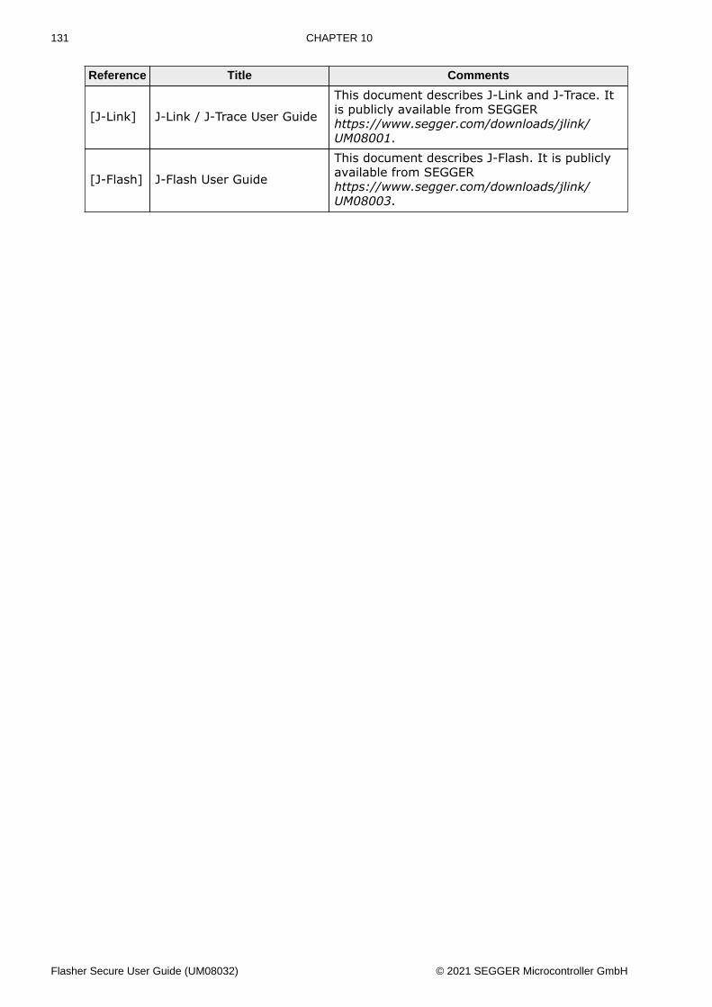
131 CHAPTER 10
Reference Title Comments
[J-Link] J-Link / J-Trace User Guide
This document describes J-Link and J-Trace. Itis publicly available from SEGGERhttps://www.segger.com/downloads/jlink/UM08001.
[J-Flash] J-Flash User Guide
This document describes J-Flash. It is publiclyavailable from SEGGERhttps://www.segger.com/downloads/jlink/UM08003.
Flasher Secure User Guide (UM08032) © 2021 SEGGER Microcontroller GmbH