flash cinematic techniques: enhancing animated shorts and interactive storytelling
TRANSCRIPT


Flash Cinematic TechniquesEnhancing Animated Shortsand Interactive Storytelling
Chris Jackson

Focal Press is an imprint of Elsevier 30 Corporate Drive, Suite 400, Burlington, MA 01803, USA The Boulevard, Langford Lane, Kidlington, Oxford, OX5 1GB, UK © 2010 ELSEVIER INC. All rights reserved. No part of this publication may be reproduced or transmitted in any form or by any means, electronic or mechanical, including photocopying, recording, or any information storage and retrieval system, without permission in writing from the publisher. Details on how to seek permission, further information about the Publisher’s permissions policies and our arrangements with organizations such as the Copyright Clearance Center and the Copyright Licensing Agency, can be found at our
This book and the individual contributions contained in it are protected under copyright by the Publisher (other than as may be noted herein). Notices Knowledge and best practice in this field are constantly changing. As new research and experience broaden our understanding, changes in research methods, professional practices, or medical treatment may become necessary. Practitioners and researchers must always rely on their own experience and knowledge in evaluating and using any information, methods, compounds, or experiments described herein. In using such information or methods they should be mindful of their own safety and the safety of others, including parties for whom they have a professional responsibility. To the fullest extent of the law, neither the Publisher nor the authors, contributors, or editors, assume any liability for any injury and/or damage to persons or property as a matter of products liability, negligence or otherwise, or from any use or operation of any methods, products, instructions, or ideas contained in the material herein. Library of Congress Cataloging-in-Publication Data Application submitted British Library Cataloguing-in-Publication Data A catalogue record for this book is available from the British Library. ISBN: 978-0-240-81261-8 For information on all Focal Press publications visit our website at www.elsevierdirect.com 10 11 12 13 5 4 3 2 1 Printed in the United States of America
website: www.elsevier.com/permissions.

iii
2 Introduction ................................................................... vii
Chapter 1: Show, Don’t Tell Me a Story
2 Anatomy of a Story ........................................................... 2
2 The Story Structure ...........................................................4
2 Make Every Scene Count ..................................................6
2 Show, Don’t Tell ................................................................8
2 Find Your Artistic Direction in Flash ................................ 12
Chapter 2: Get Into Character
2 Casting the Characters ....................................................18
2 Shaping Up .....................................................................20
2 Adopting Stereotypes ..................................................... 25
2 Exaggerating Personality ................................................. 27
2 Assembling the Cast in Flash .......................................... 32
Chapter 3: Give Me Space
2 Defining the Space .........................................................60
2 Showing the Space ..........................................................68
2 Illustrating the Space .......................................................79
2 Drawing a Storyboard ..................................................... 85
2 Building an Animatic in Flash .......................................... 87
Contents

iv Contents
Chapter 4: Direct My Eye
2 Composing the Space .....................................................96
2 Drawing the Line ............................................................99
2 Being Dominant ............................................................106
2 Having Some Depth ......................................................109
2 Focusing Attention .......................................................116
2 Simulating Depth in Flash .............................................119
Chapter 5: Don’t Lose Me
2 Manipulating Time and Space .......................................128
2 Understanding Screen Direction .................................. 130
2 Using the 180-Degree Rule ..........................................131
2 Cutting and Continuity .................................................142
2 Transitioning Scenes ......................................................146
2 Building Transitions in Flash ..........................................149
Chapter 6: Move the Camera
2 Creating New Worlds ...................................................160
2 Panning the Camera ..................................................... 167
2 Zooming ....................................................................... 172
2 Tracking Camera Movements ........................................174
2 Parallax Scrolling ...........................................................178
2 Simulating Cinematic Effects in Flash ............................186
Chapter 7: Light My World
2 Defining the Light .........................................................192
2 Lighting the Scene ........................................................196

v
2 Setting the Mood .........................................................197
2 Simulating Lighting Effects in Flash .............................. 200
Chapter 8: Speak to Me
2 Recording Audio ...........................................................220
2 Lip-Syncing Dialog ........................................................ 223
2 Mixing Sound Effects ....................................................230
2 Exploring Facial Expressions ........................................... 235
2 Posing Your Character .................................................. 241
Chapter 9: Interact with Me
2 Interactivity in Flash .....................................................246
2 Controlling Camera Movements ...................................255
2 Directing the Characters ...............................................267
2 Enhancing a Story Using ActionScript ...........................271
Chapter 10: Optimize and Publish
2 Optimizing Graphics .....................................................276
2 Preloading in Flash ........................................................ 277
2 Using the QuickTime Exporter ......................................278
2 Export ActionScript-Driven Movies ................................ 281
2 Index ............................................................................285

Flash Cinematic TechniquesEnhancing Animated Shortsand Interactive Storytelling
Chris Jackson

This page intentionally left blank

Introduction
This book focuses on the visual design of a
Flash movie using cinematic techniques: camera
placement, composition, motion, lighting, editing,
and sound. These tools not only illustrate what’s
going on in a scene, but also advance the story
and elevate its emotional impact for the audience.
22 What2Is2This2Book2About?22............................................... viii
22 Who2Is2This2Book2For?22....................................................
22 Book2Structure2and2Layout2Conventions22............................ ix
22 About2the2Author22...............................................................x
22 Acknowledgements22...........................................................xi
22 Credits22..............................................................................xi
22 For2Instructors22..................................................................xii
viii
.
.

viii2 Introduction
What Is This Book About?Flash Cinematic Techniques2maximizes2Flash’s2animation2and2production2
power2to2create2web-based2animated2short2stories,2interactive2graphic2novels2
and2online2commercials.2From2major2film2studios2to2independent2animators,2
Flash2is2employed2to2entertain,2educate,2and2promote2stories2to2their2audiences2
easily2and2effectively.2Written2for2Flash2artists2and2designers,2this2book2provides22
valuable2insights,2timesaving2practical2tips,2and2hands-on2techniques2that22
illustrate2how2to2produce2and2deploy2great2visual2stories2using2Flash.22
Flash Cinematic Techniques2focuses2primarily2on2enhancing2a2visual2story2from2
storyboards2to2the2final2project.2The2first2chapter2lays2the2foundation2to2defining2
a2good2story2and2how2to2visualize2its2structure.2Each2chapter2that2follows22
examines2visual2design2components2and2translates2cinematography2techniques2
used2in2traditional2filmmaking2into2the2Flash2environment.2Using2Flash2as2the2
authoring2tool2and2the2exercises2outlined2in2this2book,2a2reader2will2be2able2
to2produce2animated2and2interactive2cinematic2stories,2such2as2online2graphic2
novels2and2webisodes.2
The2book2is2designed2to2walk2the2reader2through2project-based2exercises2that2
effectively2use2Flash2to2enhance2their2visual2storytelling2skills.2The2first2section2
explores2visual2components2used2in2stories.2Topics2include2how2space,2line,2color,2
and2movement2can2be2framed2on2the2Flash2Stage2to2communicate2emotion2and2
meaning.2The2second2part2of2the2book2applies2cinematography2techniques2such2
as2camera2movement,2lighting,2and2editing2into2the2Flash2workspace.2
In2addition2to2animation2techniques,2Flash Cinematic Techniques2also2discusses2
adding2interactivity2using2ActionScript2to2enhance2audience2participation.22
The2last2section2of2this2book2discusses2optimization2and2publishing2tips2and2
tricks.2Chapter2exercises2consist2of2practical2applications2as2well2as2experimental2
projects.2Each2exercise2provides2step-by-step2instructions2and2tips2for2the22
reader2to2use2in2conceptualizing2and2visualizing2creative2solutions2to2their22
own2Flash2projects.
Who Is This Book For?The2book2explores2animation2and2interactive2concepts2and2techniques2for2
designing2great2visual2stories2in2Flash.2The2technical2focus2of2this2book2is2on2the2
art2direction2and2use2of2traditional2cinematography2techniques2when2building2
animated2and2interactive2short2stories2in2Flash.2Although2the2book2covers2the2
basics2in2developing2a2story,2it2is2assumed2that2the2reader2already2has2a2good2
story2in2mind2to2“show.”2The2visual2storytelling2techniques2discussed2can2be2
applied2to2entertainment,2advertising2(branding),2and2educational2applications.2

Book2Structure2and2Layout2Conventions2 ix
The2primary2audience2for2this2book2is2Flash2animators2and2designers.2These2
Flash2users2can2be2professionals2in2the2workforce,2students,2or2anyone2interested2
in2creatively2enhancing2their2animated2stories2or2interactive2projects.2This2book2
assumes2that2readers2have2some2prior2Flash2experience.2They2should2have2a2
working2knowledge2of2the2Flash2workspace2and2basic2animation2concepts.2The2
chapter2exercises2teach2readers2how2to2think2creatively2and2get2excited2about2
animation2and2interactivity2in2enhancing2visual2stories2using2Flash.2
Book Structure and Layout ConventionsFlash Cinematic Techniques2is2designed2to2walk2the2reader2through2project-2
based2exercises2that2effectively2apply2traditional2cinematography2techniques22
in2Flash2to2enhance2animated2and2interactive2visual2stories.2To2use2this2book,2
you2need2to2install2Flash2CS42or2higher2on2either2your2Macintosh2or2Windows2
computer.2If2you2do2not2have2a2licensed2copy,2you2can2download2fully22
functional2time-limited2trial2versions2from2Adobe’s2website2(www.adobe.com).2
Chapter2exercises2consist2of2practical2applications2as2well2as2experimental2
projects.2Each2exercise2provides2step-by-step2instructions2and2tips2for2the2reader2
to2use2in2conceptualizing2and2visualizing2creative2solutions2to2their2own2Flash2
projects.2Videos2used2have2been2created2in2the2NTSC2format.2
To2help2you2get2the2most2out2of2this2book,2let’s2look2at2the2layout2conventions2
used2in2the2chapters.
3 Words in bold2refer2to2names2of2files,2folders,2layers,2or2compositions
23 Menu2selections2are2presented2like2this:2Modify > Break Apart
23 Code2blocks2in2Flash2are2separated2from2the2text2like2this:
23 Icons2are2used2throughout2the2book.2Here2is2a2brief2explanation2of22what2they2are2and2what2they2mean.
2 CD:2Reference2to2files2on2the2accompanying2CD-ROM
2 Note:2Supplemental2information2to2the2text2that2sheds2a2light2on2a2
2 procedure2or2offers2miscellaneous2options2available2to2you
2 Caution:2Warnings2that2you2need2to2read
// import Flash class packages
import fl.video.*;
import fl.controls.ProgressBarMode;

x2 Introduction
All2of2the2footage,2source2code,2and2files2are2provided2on2the2accompanying2
CD-ROM2found2in2the2back2of2the2book.2Each2chapter2has2its2own2folder.2Inside2
each2folder2you2will2find2the2material2needed2to2complete2each2exercise.2Com-
pleted2versions2for2every2exercise2are2provided2in2a2Completed2folder2in2each2
chapter2folder.2As2you2work2through2the2chapter’s2exercises,2you2can2choose2to2
manually2build2the2project2or2review2the2finished2example.
All2of2the2material2inside2this2book2and2on2the2CD-ROM2is2copyright2protected.2
They2are2included2only2for2your2learning2and2experimentation.2Please2respect2
the2copyrights.2I2encourage2you2to2use2your2own2artwork2and2experiment2with2
each2exercise.2This2is2not2an2exact2science.2The2specific2values2given2in2this2book2
are2suggestions.2The2ActionScript2is2used2to2provide2a2solution.2If2you2know2of2
a2different2method,2by2all2means,2use2it.2There2are2many2ways2to2perform2the2
same2task2for2both2applications.
About the AuthorChris Jackson2is2a2computer2graphics2designer2and2tenured2professor2at2
Rochester2Institute2of2Technology2(RIT).2He2teaches2a2variety2of2graduate-
level2courses2including22D2Computer2Animation,23D2Computer2Graphics,2
Instructional2Multimedia,2and2Motion2Graphics.2Before2joining2the2RIT2faculty,2
Chris2was2a2new2media2designer2with2Eastman2KODAK2Company,2creating22
and2delivering2online2instructional2training2via2the2web2and2CD-ROM.2
Chris’2professional2work2has2received2over2252distinguished2national2and2
international2awards2for2online2communication.2His2areas2of2research2include2
user’s2experience2design,22D2character2animation,2digital2storytelling,2and2
interactive2design2for2children.2Chris2continues2to2publish2and2present2his2
research2and2professional2work2at2Adobe2MAX,2ACM2SIGGRAPH2and2the2
Society2for2Technical2Communication2(STC).2
Chris2is2author2of2Flash + After Effects2(Focal2Press,2February,22008)2and2
co-author2of2Flash 3D: Animation, Interactivity and Games2(Focal2Press,2
October22006).2His2books2have2been2translated2into2foreign2languages.
He2continues2to2be2a2Flash2animator,2designer,2developer,2and2consultant2for2
worldwide2corporations2and2nonprofit2organizations.2He2lectures2and2conducts2
workshops2relating2to2interactive2design2and2Flash2animation.2
Acknowledgements2 xi
AcknowledgementsThis2book2is2dedicated2to2my2graduate2students,2past2and2present,2in2the2
Computer2Graphics2Design2MFA2program2at2the2Rochester2Institute2of2
Technology.2Thank2you2for2your2hard2work,2dedication,2and2inspiration.
This2book2is2for2my2wife,2Justine.2Thank2you2for2all2your2unconditional2love,2
constant2support,2and2voice2talent.
This2book2is2for2my2parents,2Roger2and2Glenda.2Thank2you2for2all2your2love22
and2encouragement2to2become2an2artist.
This2book2has2taken2many2months2to2write2with2a2lot2of2time2and2effort2put22
into2making2the2examples.2I2owe2a2debt2of2gratitude2to2all2at2Focal2Press,2but2
especially2Paul2Temme,2Anais2Wheeler,2and2Anne2McGee.2Thank2you2for2all22
your2support2and2advice2in2enabling2me2to2bring2this2book2to2print.
Special2thanks2goes2to2two2of2my2Computer2Graphics2Design2students2at2RIT,2
Brian2Kowalczyk2and2Karli2Tucker.2Thank2you2for2graciously2agreeing2to2let2me2
reproduce2some2of2your2work2with2permission2in2this2book.2Use2of2their2work2
is2limited2strictly2to2the2published2SWF2examples2provided2on2the2CD-ROM.
CreditsThe2following2stock2images2from2iStockphoto.com2were2incorporated2into2
chapter2artwork2to2illustrate2cinematic2techniques:2
3 Cityscape at Night,2illustration2courtesy2of2iStockphoto,2Stay2Media2Productions,2Image2#1564950
3 Cowboy in the dusk,2illustration2courtesy2of2iStockphoto,2Belkarus,2Image2#9481995
3 Exhaustion,2illustration2courtesy2of2iStockphoto,2id-work,2Image2#10507830
3 Forest Fire,2illustration2courtesy2of2iStockphoto,2Steven2Foley,2Image2#5211596
3 Hard Cop,2illustration2courtesy2of2iStockphoto,2Bruno2Cullen,2Image2#7839117
3 Light through a door,2illustration2courtesy2of2iStockphoto,2ALXR,2Image2#8685748
3 Metropolis,2illustration2courtesy2of2iStockphoto,24x6,2Image2#9207032
3 Railroad Track,2illustration2courtesy2of2iStockphoto,2
Adini2&2Malibu2Barbie,2Image2#8235904

xii2 Introduction
For InstructorsFlash Cinematic Techniques2provides2hands-on2exercises2that2demonstrate2core2
features2in2Flash.2As2an2instructor,2I2know2you2appreciate2the2hard2work2and2
effort2that2goes2into2creating2lessons2and2examples2for2your2courses.2I2hope2you2
find2the2information2and2exercises2useful2and2can2adapt2them2for2your22
own2classes.
All2that2I2ask2is2for2your2help2and2cooperation2in2protecting2the2copyrights2of2
this2book.2If2an2instructor2or2student2distributes2copies2of2the2source2files2to2
anyone2who2has2not2purchased2the2book,2that2violates2the2copyright2protection.2
Reproducing2pages2from2this2book2or2duplicating2any2part2of2the2CD-ROM2is2
also2a2copyright2infringement.2If2you2own2the2book,2you2can2adapt2the2exercises2
using2your2own2footage2and2artwork2without2infringing2copyright.
Thank2you2for2your2cooperation!

Chapter 1
Show, Don’t Tell Me a Story
Animation is all about showing, not telling a story,
but what makes a story good? A good story needs
a compelling plot that involves appealing characters
living in a believable world. Understanding the
story structure and how to visualize it using Flash
is the topic of this first chapter.
2 Anatomy of a Story ............................................................ 2
2 The Story Structure ............................................................. 4
2 Make Every Scene Count ................................................... 6
2 Show, Don’t Tell ................................................................. 8
2 Find Your Artistic Direction in Flash ...................................12
©2010 Elsevier Inc. All rights reserved. DOI: 10.1016/B978-0-240-81261-8.50001-5

2 Chapter 1: Show, Don’t Tell Me a Story
Anatomy of a StoryStories always start with an idea. Ideas can come from all around you—from
your imagination, personal observations, life experiences, to your dreams and
nightmares. These random thoughts or observations are recorded as events.
Events are then woven together to formulate the story’s plot.
The plot is not the story itself; it is all of the action that takes place during the
story. How the action affects the characters physically and emotionally builds
a good story. The fundamental components to any story involve a character
or characters in a setting, a conflict that causes change, and a resolution that
depicts the consequences of the character’s actions.
Take a look at the following nursery rhyme:
HumptyDumptysatonawall;
HumptyDumptyhadagreatfall.
AlltheKing’shorsesandalltheKing’sMen
Couldn’tputHumptytogetheragain.
Figure 1.1:Storiesinvolveacharacterinasetting,aconflictthatcauseschange,andaresolution.
Deceptively simplistic in nature, this nursery rhyme contains all of the necessary
building blocks to tell a story (Figure 1.1). The first line establishes the main
character in a setting. The second line introduces conflict by having the
character fall. A change occurs with all the King’s horses and men coming to
Humpty’s aid. The last line is the resolution; the main character remains injured
as a result of his actions. The story is simple, but is it compelling? Perhaps not.
Humpty Dumpty is a one-dimensional character. He exhibits very few charac-
teristics that an audience can relate to. Let’s add some element of interest to
the rhyme. What if Humpty Dumpty was warned by his mother not to sit on

Anatomy of a Story 3
Figure 1.2:Addinginteresttoyourstorytriggersthisemotionalresponse.
the wall, but disobeyed? What if Humpty Dumpty was depressed and delib-
erately jumped? What if all the King’s Horses and all the King’s Men secretly
conspired to get rid of Humpty (Figure 1.2)? Now the story takes on more
meaning for the audience. Their curiosity is piqued as they seek out answers
from the storyline.
A good story is judged by the emotional impact it has on its audience. Adding
interest to your story triggers this emotional response. Audiences want to be
able to relate to the characters. Once bonded, audience members experience
the turmoil the characters go through by projecting themselves into the story.
Audiences also anticipate the dramatic tension created by the conflict and want
to know what is going to happen next. Without any emotional involvement,
a story is reduced to a series of events.
Storytellers typically employ a dramatic story structure to determine when
certain events will happen to achieve the greatest emotional response from

4 Chapter 1: Show, Don’t Tell Me a Story
the audience. This structure can be applied to a three-hour movie or to a
30-second commercial. Developed by the Greek philosopher Aristotle, it has
become the narrative standard in Hollywood. Audiences are quite familiar
with it and even come to expect it.
The Story StructureThe dramatic structure consists of a beginning, middle, and an end (Figure 1.3).
Each act applies just the right amount of dramatic tension at the right time and
in the right place. Act One is called exposition and it gives the audience infor-
mation in order to understand a story. It introduces the setting, the characters,
their goals, and the conflicting situation that the story is about.
Figure 1.3:Thedramaticstorystructuredetermineswheneventswillhappeninastory.
The setting is where and when the story takes place. When developing your
story ask yourself where is the story set: on another planet? in a car? under-
water? Does the story occur in the past, present, or future? With the setting
in place, you next need to populate your world with characters. It is important
to note that the world, its timeline and occupants, all need to be believable to
the audience. That doesn’t mean it has to be realistic. Walt Disney summed it
up best with the term “plausible impossible.” It means that it is something
impossible in reality but still can be convincingly portrayed to the audience.
There are often two types of characters in a story: the hero (protagonist) and
the villain (antagonist). The hero is the main character and has a strong goal
that he must achieve without compromise. The villain will stop at nothing to
prevent the hero from succeeding. Audiences typically root for the hero as he
faces a series of ever-increasing obstacles created by the villain. The opposing
goals of the hero and villain create the story’s conflict.

The Story Structure 5
Act Two focuses on the conflict. Conflict is the most important element in a
story. The problems faced by the characters make the story exciting. The key
to creating good conflict is to make the villain stronger than the hero at the
beginning. Usually the villain is another person, but can be an animal, nature,
society, a machine, or even the hero himself battling an inner conflict. Through-
out the story, the villain needs to pursue his own goal as actively as the hero.
Audiences love a great villain who is as complex and interesting as the hero.
If the hero can easily beat the villain, you don’t have a good story. In order
to engage the audience emotionally, they must empathize with the hero. The
hero should be someone the audience can feel something in common with, or
at least care about. Empathy links the hero’s challenges and experiences to the
audience. One way to do this is to give the hero certain weaknesses at the
beginning of the story that can be exploited by the villain. These weaknesses
drive the conflict and raise the audience’s emotional connection or bond to the
hero. As the character wrestles with the conflict, the audience wrestles with
him and cares about the outcome (Figure 1.4).
Figure 1.4:Empathylinksthehero’schallengesandexperiencestotheaudience.
Act Two drives the story forward raising the tension. The villain constantly cre-
ates new obstacles causing the hero to struggle towards his goal. The tension
reaches a high point at the end of Act Two. This is also referred to as the climax
or turning point, when the plot changes for better or for worse for the hero.
During this moment, the hero takes action and brings the story to a conclusion.

6 Chapter 1: Show, Don’t Tell Me a Story
Act Three is the resolution and end of the story. It resolves the conflicts that
have arisen. Act Three ties together the loose ends of the story and allows the
audience to learn what happened to the characters after the conflict is resolved.
This is often referred to as closure. Storytellers often start developing stories by
figuring out the climax or the conclusion of the story and then work their way
backwards.
AstorystructureworksheetisprovidedintheChapter_01folderforyoutousewhendevelopingyourstory.
This dramatic structure provides a framework for a story. Stories created in
Flash tend to be less complex than feature films or even television shows.
Usually these are short stories that focus on only one incident, have a single
plot, a single setting, a couple of characters, and cover a short period of time.
As you begin developing your story in Flash, decide what the audience needs
to know and when to add the dramatic tension. Start by showing a path for
the audience to follow. Give them visual clues to what is going on in the
opening scene. With the compressed format in Flash, it makes cutting to the
chase all the more essential.
Make Every Scene CountUnderstanding story and its structure is important, but you are working in a
visual medium. As a visual storyteller, you can enhance a story’s emotional
experience by showing how a story unfolds through a sequence of images.
However, creating beautiful imagery is not enough if the visuals do not
reinforce the story’s narrative or meet the audience’s expectations.
For each scene in your story, you need to visually answer the following
three questions that audience members ask. They are:
1. What is going on?
2. Who is involved?
3. How should I feel?
Most stories created in Flash range from 30 seconds to two minutes in duration.
That is not a lot of time to divulge a complex plot. You need to make every
scene count by either advancing the story or developing the characters. It
is best to throw the audience into the action after the title scene and create
enough tension to start the audience worrying about the characters. Director
Alfred Hitchcock strongly believed in giving his audience just the right amount
of information to get them involved with the story. Hitchcock’s “bomb theory”
is widely referenced as a good visual storytelling technique in building
suspense (Figure 1.5).

Make Every Scene Count 7
Figure 1.5:AlfredHitchcock’sappliedhis“BombTheory”tohisfilmstoaddsuspense.
The theory illustrates the difference between suspense and surprise. An audi-
ence would view two people having a conversation seated in a café as an
ordinary scene, nothing special. The scene doesn’t offer much to the audience
in terms of involvement or participation. Then all of a sudden, “Boom!” There
is an explosion. The audience is in shock for about 15 seconds. They had no
prior warning about a bomb, but what if they did?
Rewind the scene back to the two people talking in the café. This time show
the audience that there is a bomb underneath the table. Show the audience
that it will explode at one o’clock. Show a clock on the wall behind the two
people; the time is five minutes to one. What happens to the audience?
Figure 1.6:Knowingmoreinformationthanthecharactersisawaytogettheaudienceclosertoyourstory.

8 Chapter 1: Show, Don’t Tell Me a Story
The audience’s involvement in the scene becomes much greater than before.
They know more information than the characters and want to warn them. The
scene’s sequence of images (bomb, the timer, and the clock on the wall) serves
as a visual tool to draw the audience closer into the story (Figure 1.6). Hitchcock
wasn’t called the Master of Suspense for no reason.
Show, Don’t TellThe best rule to follow when visualizing a story is to always show, don’t tell.
At the beginning of your story, it is important that the audience knows some
information in order to understand the story. In Act One, the exposition will
often have information about events that happened before the story began.
Exposition gets the audience up to speed on the setting and the characters.
An inherent problem with exposition is that you could have too much and
potentially bog down your story before you ever get to the action. This is
where visual storytelling can truly shine. Let’s take a look at another Hitchcock
example. In his film RearWindow (1954), the protagonist spies on his neigh-
bors through his apartment window and becomes involved in a murder mystery.
The opening scene is a masterful example of using visuals to “show” the story
without saying a word to the audience (Figure 1.7).
Hitchcock starts the scene by showing the New York apartment building where
the protagonist lives. The audience sees the cast of characters in each of their
apartments going about their daily routine. The camera travels inside the pro-
tagonist’s apartment to show him asleep in his wheelchair and the thermometer
at 90°. The camera moves down his left leg to show that it is in a full cast. His

Show, Don’t Tell 9
Figure 1.7:Expositiongetstheaudienceuptospeedonthesettingsandthecharacters.
name, L.B. Jefferies (played by actor Jimmy Stewart), is on the cast. The camera
moves around Jefferies’ apartment to show his smashed camera, the amazing
shot that broke both the camera and his leg, and finally a positive and negative
photograph of a female model on the cover of a glamour magazine.
The dialogue-free exposition sets the audience up for all of the events that oc-
cur later in the film. It is the camera’s movement in composing the scene that
shows the protagonist, his profession as a photographer, his physical weakness
that leads to his voyeurism, the neighbors that he spies on, and a hint about his
love life played by actress Grace Kelly. In visual storytelling, this is often referred
to as planting information that the audience absorbs without even being aware
of doing so. When the information gives meaning to events later in the story it
is referred to as payoffs.
Another good example of a plant and payoff occurs in the movie Raidersof
theLostArk (1981). The hero, Indiana Jones, physically shows the audience he
has a fear of snakes in the beginning of the film. The audience finds the scene
humorous because the hero just survived an entire tribe of warriors trying to
kill him only to wimp out over a snake on a plane. The payoff comes later in
the film when Indy’s quest leads him to a tomb filled with thousands of snakes.
He must make a decision to face his fears in order to achieve his goal of
retrieving the Ark of the Covenant. Of course it’s also a great suspense builder
making the descent into the tomb scarier because the audience feels and sees
Indy’s revulsion.

10 Chapter 1: Show, Don’t Tell Me a Story
Sometimes there is just too much exposition to show and you need to tell it to
the audience using text or voice-over narration (Figure 1.8). StarWars(1977)
is a great example of using text to tell the audience all the background informa-
tion on the characters and setting at the beginning of the story. The episode
starts with scrolling paragraphs of text explaining the entire back story that has
led to this moment. Then the action begins.
Figure 1.8:Sometimesyouneedtotelltheexpositiontotheaudienceusingtext.
Voice-over narration is effectively used in TheShawshankRedemption (1994).
The story is narrated by an inmate named Red (played by actor Morgan Free-
man) set in a fictional penitentiary in Maine. His narration throughout the film
provides the emotional connection between the audience and the protagonist,
Andy Dufresne (played by actor Tim Robbins).
In addition to exposition, visual elements can also enhance transitions between
acts in the story. In TheWizardofOz (1939), the protagonist, Dorothy (played
by actress Judy Garland), is introduced as a farm girl who lives in Kansas with
Figure 1.9:Colorhasbecomeaneffectivetooltodrawtheaudienceintothestory.

Show, Don’t Tell 11
her aunt and uncle. Kansas is shown in a sepia tone. The color symbolizes the
drabness of the setting. After a tornado whisks Dorothy away, over the rainbow,
to the Land of Oz she tells the audience, “We’re not in Kansas anymore.” Color
is used to reinforce that plot point. The color transitions from sepia tones used
in Act One to full Technicolor glory at the beginning of Act Two.
Over the years, the use of color has become an effective visual tool to draw
the audience into the story. Steven Spielberg’s film Schindler’sList (1993) is
primarily in black and white. However, in one scene a little girl is shown wearing
a red coat. Through contrast in color, the audience’s attention is immediately
drawn to her as she wanders alone amid the horrors of World War II.
The red symbolizes the protagonist’s (played by actor Liam Neeson) awareness
to the cruelty being committing against the Jews. Audiences visually and emo-
tionally connect with the girl and search for her red coat in scenes that follow
(Figure 1.9). Will she be saved? Sadly, the sight of her red-tinted coat among
the dead becomes one of the film’s most harrowing images.
Based on these examples, you can see that movies are an excellent resource for
learning more about visual storytelling. Before you start designing your story in
Flash, watch some of your favorite movies. Mute the audio so you can focus
exclusively on the story’s imagery. If you can, pause the movie on a frame that
you find visually appealing.
Study its composition, use of color, and camera placement. Subsequent chapters
in this book will discuss these cinematic tools in depth. For now, sketch out the
visual structure you find effective in “showing” the story you are watching.
Figure 1.10:Sketchoutthecompositionofscenesyoufindappealinginmovies.

12 Chapter 1: Show, Don’t Tell Me a Story
Remember, one of the goals in creating your Flash story is to have people watch
it. Once you have a good story you need to show as much as possible to your
audience rather than tell them. Each scene must clearly illustrate to the audience
what is going on, who is involved, and how they should feel about what they
are seeing. Meeting the audience’s emotional expectations is achieved through
your creativity and art direction. So what visual style works well in Flash?
Find Your Artistic Direction in FlashAnimation captivates its audience through the magic of making things move
from static images. It is a very dynamic art form with varying artistic styles.
Animation can be achieved through traditional (hand-drawn) animation, stop-
motion, and 2D and 3D computer animation. Flash was originally designed to
create 2D computer-generated animation for the web.
2D animation techniques and tools have changed considerably over time. The
early pioneers in animation drew a sequence of images and then photographed
them in order to create the motion. Today, Adobe Flash is packaged with
automated computerized versions of traditional animation techniques such as
tweening, morphing, and onion skinning. Its format and workspace allows you
to save a considerable amount of time and therefore reduce a project’s budget.
Figure 1.11:Vectorartusesmathtostoreandcreateanimagemakingitresolution-independent.
Flash is well known for its inherent visual look which is vector-based. Vector art
uses math to store and create an image. This makes the artwork resolution-
independent. It can be scaled without losing any detail. As a result, vector-

Find Your Artistic Direction in Flash 13
based artwork produces rather small file sizes that are ideal for web delivery.
The only drawback to using vectors is that the artwork becomes less
photorealistic and more mechanical, potentially losing the organic feel of
traditional hand-drawn animation.
Figure 1.12:Rastergraphicsaremadeupoftinyunitscalledpixels.
Raster graphics, also called bitmaps, are made up of tiny units called pixels.
Pixels are grouped together in a grid that forms the image. The resulting image
can be photorealistic but larger in file size.
Another drawback to raster images is scalability. If a raster graphic is scaled too
large, the pixel grid will become noticeable, creating a pixellated image (Figure
1.12). If the raster image is optimized properly, Flash can produce outstanding
photo-collage animation, often referred to as cutout animation (Figure 1.13).
Figure 1.13:Paper,fabric,andphotographscanbeusedtocreatecharacters.

14 Chapter 1: Show, Don’t Tell Me a Story
Figure 1.14:Limitedanimationusesanon-realisticstylethatdepictscaricaturesratherthanlifelikerepresentations.
Cutout animation is a technique for creating collaged characters and back-
grounds from materials such as paper, fabric, or photographs that were scanned
into the computer. The animated TV series SouthParkand JibJabMedia (www.
jibjab.com) online are two great examples of computerized cutout animation.
When viewing this style of animation you will notice that the movements of the
collaged parts are never as fluid as in traditional animation. This is sometimes
called “limited animation.”
In the 1950s TV animators began experimenting with a new artistic style that
focused more on design than realism. United Productions of America, better
known as UPA, was one of the first American animation studios to abandon the
realistic approach perfected by Walt Disney in favor of stylized design. The first
UPA animation, GeraldMcBoing-Boing(1951), was visually like nothing audi-
ences had seen before. The theatrical cartoon won an Academy Award for Best
Animated Short and was a major step in the development of limited animation.
The visual style uses abstract art, symbolism, and limited movement to achieve
the same storytelling effect of high-end animation but with lower production
costs (Figure 1.14). Though cost-cutting measures abused the art form in later
years, GeraldMcBoing-Boing and other UPA animated shorts were meant as
an artistic exercise rather than a quick way of producing cheap cartoons.

Summary 15
The process of limited animation reduces the overall number of drawings. Static
and sequences of images are used over and over again. For example, animators
only have to draw a character walking once. Characters are split up into differ-
ent parts on separate layers. Only portions of a character, such as the mouth
or an arm, animate at a time. If you watch any cartoons from the 1960s and
‘70s produced by Hanna-Barbera (Scooby-Doo,YogiBear) you will see clever
choices in camera angles, editing, and the use of camera techniques such as
panning to suggest movement.
Flash, with its reusable symbols, tweening features, and the need to reduce file
size for the web, is the perfect application for producing limited animation. The
word “limited” doesn’t mean inferior in terms of animation. It is important to
understand the concept of limited animation because it dictates how you design
your characters, props, and backgrounds for it.
Whichever visual style you choose for your story, there are many ways to make
the artwork in Flash rich with spontaneity and life. The next chapter examines
different techniques that can help you to design characters in Flash that are
dynamic and appealing to your audience.
SummaryToday, Flash has revolutionized the animation production process by building on
the limited animation techniques used in the past. It has become a professional
tool for developing high-quality animation for the web and broadcast. A typical
production pipeline for a Flash animation is shown in Figure 1.15.
Figure 1.15:TheproductionpipelineforatypicalFlashanimation

16 Chapter 1: Show, Don’t Tell Me a Story
This completes the chapter on story, its structure, and how to begin to “show,”
not tell, it to your audience. A good story is judged by the emotional impact it
has on its audience. Understanding its structure is a key factor in making your
stories great. Most animation begins with the development of a story.
Once your story is developed, the next step is to determine the “look,” or art
direction of your Flash story. The best thing about Flash is that it allows artists
to show their stories in any style they can imagine. Will your characters be
hand-drawn and scanned into Flash? Created from stock photography? Self
created directly in Flash? The next chapter explores each of these techniques
to help you decide which artistic vision best illustrates your story.

Chapter 2
Get into Character
The key to an effective story is the appeal of its
characters. Characters come in all shapes and sizes.
Creating a unique and compelling character often
begins with a distinct look. This chapter explores
character design and how to effectively incorporate
different visual styles in Flash.
2 Casting the Characters ..................................................... 18
2 Shaping Up ...................................................................... 20
2 Adopting Stereotypes ....................................................... 25
2 Exaggerating Personality .................................................. 27
2 Assembling the Cast in Flash ............................................ 32
©2010 Elsevier Inc. All rights reserved. DOI: 10.1016/B978-0-240-81261-8.50002-7

18 Chapter 2: Get into Character
What is your character going to look like? The answer is completely up to you.
Character design is an art form unto itself. As you read in Chapter 1, there are
different artistic directions that can be used in Flash. This chapter is not going
to promote one specific direction to follow over another. Instead, let’s look at
some basic guidelines that, if used, will improve your character designs in Flash.
Casting the CharactersDuring the pre-production stage in film, the producer, director and writer
determine the type of actor they need to cast for each character’s role. You
must perform a similar casting by creating a mental image of each character
that visualizes its unique physical characteristics.
Before you start sketching out your characters, reread the story you have
chosen to animate or make interactive. Answer the following questions that
your audience will want to know:
3 What is the character’s physical body makeup?
3 Two arms and two legs? Four legs? Eight tentacles?
3 Does the character resemble a person, an animal, a plant, an object, or something no one has ever seen before?
3 Is the character’s body thin, overweight, muscular, or soft?
3 Is the character tall, short, or hunched over?
3 Is the character male, female, or something else?
3 Does the character walk, slither, fly, or swim?
3 What colors identify the character?
3 What type of clothes does the character wear, if any?
After picturing the visual look, think about the character in regards to the
animation capabilities and limitations in Flash. When casting your character
for the Flash Stage, ask yourself:
3 Is the character the center of interest or merely a prop?
3 How big is the character in relation to the other characters? The background? The props?
3 Does the character animate? How much does the character move?
3 Will the audience see the character from different angles?
3 Does the character speak?
The goal is to design an appealing character for the audience plus have the
design be conducive to Flash. To do this, compare the visual look to the
technical capabilities in Flash. If the character is seen from multiple angles, you
need to create these additional views, which takes time. Knowing if a character
animates or speaks will impact the complexity of the design. The simpler the
design, the easier it is to animate.
Casting the Characters 19
Flash cartoon characters are often composed of several layers. It is good
practice to create a different layer for each body part. The benefit you gain
is more flexibility in adjusting or changing your character. If you plan to
animate, the layers provide you the ability to fine-tune each part’s movement.
The number of layers is up to you.
The best advice when working in Flash is to simplify when possible. That
doesn’t mean create stick figures; no offense to stick figures. The word
“simplify” means design clarity. There should always be a minimum amount
of detail, no more than you need to recognize the character clearly.
Remember the old saying, “The devil is in the details.” The audience will be
able to identify each character based on their general look and not by the
number of hairs on their head or freckles on their face. So, where do you start?
Figure 2.1: Simplify your design. The simpler the design, the easier to animate in Flash.

20 Chapter 2: Get into Character
Shaping UpSimplify the design by building your characters out of basic shapes. Look at the
world around you; you should be able to distinguish squares, rectangles, circles,
ovals, and triangles present in almost everything you see. These basic shapes
become the building blocks for your character’s design.
These shapes can also help the audience understand what type of character
it is. Each shape subliminally conveys a different personality trait. The shapes
you choose become the underlying structure for your character’s makeup and
personality. Let’s take a look at some character designs using basic shapes.
Squares and Rectangles
Characters built primarily out of rectangles tend to be big, muscular jocks,
superheroes, bullies, and military characters. Square and rectangular shapes
suggest strength, dependability and also unintelligent, as in the phrase
“blockhead.” Figure 2.2 illustrates how the tough guy was built using cubes.
Figure 2.2: Rectangular shapes suggest strength.
Circles and Ovals
Circular shapes are used for characters with small bodies, for example, children.
Familiar cartoon characters such as Charlie Brown and the Power Puff Girls have
heads made out of one big circle. A character constructed out of circular, round
shapes appears soft, cuddly and non-threatening (Figure 2.3).

Shaping Up 21
Figure 2.3: Rounded shapes suggest cute, cuddly and non-threatening.
Transforming a circular shape can create different meanings for the audience.
If a circle is stretched, the oval shape could be considered for a character that
is goofy or thin. If the circle is squashed, it could suggest that the character is
jolly and/or overweight.
Figure 2.4: Transforming the sphere shape can imply different personality traits.

22 Chapter 2: Get into Character
Triangular Shapes
Similar to rectangles, triangluar shapes can be used for strong characters that
have a chiseled jawbone structure or a really large neck. If the triangle is turned
upside down, the resulting shape can be used for female characters (Figure 2.5)
or nerdy characters that lack self-confidence.
Figure 2.5: Triangular shapes can suggest strong characters or just the opposite.
These shapes are by no means your limit in character design. Use them as a
starting point. Remember, you can stretch, squash, poke, pull, and combine
these shapes together to build your character. Two spheres can create a bean
or pear shape that is a common design used in animation. A cone can be
morphed into a teardrop shape.
Start sketching your characters to determine which shapes best suits them.
The possibilities are endless (Figure 2.6). Don’t worry about making mistakes.
Accidents can become interesting facets of your character’s design. Look over
your sketches and note which aspects of the character’s design you would
like to keep and which you can ignore.
Creating Model Sheets
Once you have decided on a basic design for your character, practice draw-
ing its body and several poses. Personality is expressed through the character’s
posture and movement. As you assemble your character, create a model sheet.
Character model sheets detail the visual design of a character from a variety

Shaping Up 23
Figure 2.6: Experiment with the basic shapes to determine which shape best suits your character design.
of angles and poses. Think about who your character is and what actions they
perform in the story. Then sketch out a series of action poses (Figure 2.7).
Figure 2.7: The line of action defines the character’s posture and movement.

24 Chapter 2: Get into Character
Figure 2.8: A character turnaround illustrates its construction and proportion.
Similar to a gestural drawing, sketch a line of action for each pose. This is an
imaginary line that travels through the entire figure from the top of the head,
down the spine, and out through the hands and feet. Its curvature defines the
character’s posture and movement.
The line of action should always be sweeping curves or diagonal lines that are
active. Avoid drawing vertical lines as they stiffen the character and make it
uninteresting to the audience. The more curved the line of action is, the more
dynamic the character’s pose will be. Chapter 8 explores Flash character
animation techniques and staging in more detail.
For now, keep your sketch loose to capture the action of the pose. Once
the line of action is established, add your basic shapes to it. Use three
dimensional forms with axis lines. Axis lines act like a wire frame to help you
see the dimension.
Connect the forms using simple lines to build the body structure. Attach the
legs and hips to the bottom of the body. Draw cylindrical shapes for the arms
that end in spheres at the shoulder. The neck is added on the front side of
the body not centered. The details, such as clothes, are the last elements you
add to a character design.
A model sheet typically contains a number of rough sketches that bring your
character to life. In addition to the poses, draw the character from all views:
Adopting Stereotypes 25
front, back, three-quarter, and profile. This is also referred to as a character
turnaround or character rotation. These views help you understand the
character’s construction and proportion (Figure 2.8).
Keep in mind the subliminal connotations associated with each shape. If your
character is soft and delicate, build its body out of round shapes. The more
hard edges and angles in the design, the more the character will be seen as
active, aggressive, dominant, and sometimes evil. Villains are often angular in
design. Study the classic Disney villains such as Cruella De Vil from 101 Dalma-
tians (1961), Jafar from Aladdin (1992), and Hades from Hercules (1997).
This is not to say that you have to make a stereotypical character. We all carry
mental pictures of what different types of characters should look like. Theses
stereotypes have been ingrained in us through the constant bombardment of
television, movies, books, and the web. Be aware of these preconceptions
before you design your characters. They can, in fact, work to your advantage.
Adopting StereotypesIf you were shown an image of a young man in a ten-gallon hat, wearing chaps
and jingling spurs you would recognize the character as a cowboy. The class
nerd wears glasses held together with tape, has a pocket protector in his plaid
shirt, and wears pants hiked up past his belly button. Not all scientists have a
bald head, a mustache, and wear a white lab coat but this image is a generally
accepted stereotype (Figure 2.9).
Figure 2.9: Generally accepted stereotype for a cowboy and a mad scientist.

26 Chapter 2: Get into Character
These stereotypes are caricatures that audiences associate with. A caricature
exaggerates or distorts distinguishing features of a person or thing to create an
easily identifiable likeness. It captures the essence of the character by accenting
only the details that are visually defining. So what goes into making a stereo-
typical character?
Think about the character’s body. In addition to its face, the character’s posture
often suggests its demeanor. A happy-go-lucky character can be portrayed as
round, openly expressive with an upright stance. An irritable, down-right nasty
character can be shown crouched over with shriveled features and a defiant
posture (Figure 2.10).
Figure 2.10: The character’s posture suggests its demeanor.
Clothes also make the character. In general, the happier the character is, the
lighter, brighter, and more colorful its clothes usually are. Conversely, a gloomy
character is often drawn in dark, ill-fitting clothes that stick to its body. Cloth-
ing can indentify the character’s occupation such as a police officer, chef, doctor,
fireman, and so on. Clothing also places characters in their historical context.
Don’t just copy a stereotype, expand on it. Sometimes it is good to break all the
rules and go against the accepted stereotype. For example, the character Sulley
from Monsters Inc. (2001) is a huge, furry monster with sharp teeth, but his
personality is that of a gentle giant that wouldn’t harm a fly.
Remember to think about these attributes when designing your characters.
Since stories animated in Flash tend to be short in duration, you would do your-

Exaggerating Personality 27
Figure 2.11: Clothing can establish the character’s occupation and the historical timeline they live in.
self a favor in considering adopting these “types.” Your audience will accept the
storyline more quickly when the characters are familiar and easily identifiable.
Visually, each character in your story should be unique with distinct physical
details. Watch any cartoon or animated film. Do the characters look like real
humans or animals? No. There is some degree of caricature present to make
each character stand out. Exaggeration is the key to individuality.
Exaggerating PersonalityJust like there are different types of people, there are different types of
characters. Exaggerating the defining features of your character helps the
audience to identify its type. Character types include the following:
3 Cute as a Button
3 The Girl Next Door
3 Tough Guy
3 The Average Joe or Jane
3 Mad Scientist
3 Grumpy Old Man
3 The Nerd
3 The Rebel
3 The Comic Relief

28 Chapter 2: Get into Character
Your character should always look the part. For example, if you are designing
a cute character, it typically is constructed out of round shapes with the propor-
tions of a baby. They have chubby arms and legs. The proportion of the head
is often larger than the overall height of the body.
Tough guys have an overly expanded chest, huge shoulders, and bulging
biceps. Their heads sit low on the body with no neck visible. Small legs draw
attention to the massive upper body. The exaggeration in correct human
body proportions is an important concept to understand when creating
exaggerated caricatures.
Basic Character Proportions
The average human adult is about six to eight heads tall. What does that mean?
Take a look a Figure 2.12. Use the character’s head as a unit of measurement;
stack a bunch of heads on top of each other. An adult human character would
be six to eight of those heads tall including the head of the character.
Figure 2.12: Use the character’s head as a unit of measurement.

Exaggerating Personality 29
The age and gender of your character determines how many heads tall the
character should be. The unit of measurement doesn’t change; it’s always
based on the height of your character’s head. A child has a much smaller
head ratio of about two to three. A mother is about five to seven heads tall.
Remember that this is a general rule for characters that mimic human pro-
portions. If you are creating more of a caricature, you do not need to fit
the character exactly within these dimensions but it does give you a starting
point that you can use.
Contrasting Characters
If you are building more than one character, keep in mind that they all need
to live together in the same environment. In order to get along, all characters
should share a fairly similar visual style. A good way to see this is to line them
all up next to one another. Make a size comparison chart that show’s each
character’s size relative to the other characters in the story. The end result
looks something like a police line-up (Figure 2.13).
Figure 2.13: Create a character size comparison chart to make sure they all share the same visual style.
Having a similar visual style does not mean that you have to forego contrast.
There is truth in the saying, “Opposites attract.” If all your characters shared
the same physical build with the only difference in design being clothes, who
would you focus on more? Audiences need to be intrigued by your character’s
individuality and contrast is a good method to use.

30 Chapter 2: Get into Character
Two characters that contrast well against each other are always more interesting
than two characters who are exactly the same. As you read in Chapter 1, stories
have a least two characters, or two sides to a character. Think about popular
cartoon duos: Tom and Jerry, Yogi Bear and Boo Boo, Snoopy and Woodstock.
Both characters differed in physical height, build and color.
Using Color
Let’s focus on color. Certain colors communicate information about a character.
It is generally accepted that red can be passionate and sometimes dangerous.
Blue is cold and masculine, while a lighter shade can be perceived as feminine.
Yellow conveys a sense of being cheerful, bright, and it is eye catching.
Figure 2.14: What does each character’s color communicate?
The color green symbolizes healthy and alive. Purple is associated with royalty.
Orange is warm and inviting. Neutral grays are rather dark and mysterious. The
color brown is considered earthy and old. Be aware of these color connotations
in designing your characters because the audience will pick up on their mean-
ings subconsciously. What about black?

Exaggerating Personality 31
To make sure your character stands out in the crowd fill in its outline using black.
Only using positive and negative space removes all detail except the defining
outline of the character. A memorable character can be reduced to a silhouette,
and still be immediately recognizable (Figure 2.15).
Figure 2.15: A memorable character can be immediately recognized through its silhouette.
German filmmaker Lotte Reiniger is a pioneer in silhouette animation. Her
65-minute film Die Abenteuer des Prinzen Achmed (The Adventures of Prince
Achmed) is widely considered to be the world’s first animated feature. Her
method of animation was simple.
Lotte cut out a character’s body parts from black paper and joined the parts
together using wire hinges. The figure was then arranged on a horizontal glass
table lit from below. A camera directly overhead exposed one frame of film at
a time. After a slight modification in the position of the figure, another frame
was exposed. Her visual style was an expressive use of shape, form, and
positive and negative space.
Going Graphic
The artistic style of the United Productions of America (UPA) cartoons in the
1950s favored a more graphical design approach than a realistic one. Their
cartoons revolutionized a whole new approach in visual storytelling. Popular
cartoons shown today (Cow and Chicken, Edd ‘n Eddy, Dexter’s Laboratory,
The Grim Adventures of Billy & Mandy) on the Cartoon Network and
Nickelodeon push the graphic boundaries established by UPA to the extreme.

32 Chapter 2: Get into Character
Instead of building the characters out of various primitive objects, this style
focuses more on using interesting shapes that define the character’s outline
(Figure 2.16). The outlines are created using thick, bold strokes with thinner
lines used for detail. Detail is optimized to keep only what is necessary to
identify the character.
Figure 2.16: Focus on using interesting shapes that define your character.
Even though these thick outlines create rather flat imagery, attention is given to
contrasting straight and curved lines. This gives the character a more dynamic
look. Flash designers have adopted this graphic style because its simplicity in
design lends itself well to Flash’s built in tools and animating capabilities.
Assembling the Cast in FlashFrom your various sketches, model sheets, and turnarounds, it is time to
assemble the character in Flash. There are many ways to do this. The following
exercises provide some tips and techniques in building your characters to use
in animation, interactive projects, or as mascots for branding design.
As mentioned in the introduction, this book assumes that you have a
working knowledge of Flash, its workspace and drawing tools. Feel free to
substitute your own artwork in place of what is provided on the CD-ROM.
Let’s get started.

Assembling the Cast in Flash 33
Locate the Chapter_02 folder on the CD-ROM. Copy this folder to your hard drive. The folder contains all the files needed to complete the chapter exercises.
Exercise 1: From Paper to Pixels to Vectors
In traditional hand-drawn animation, a character’s outlines were inked and
then filled with color and shading. It was a tedious and time-consuming job
with thousands of hand painted cels. Flash has simplified the process digitally
through its easy-to-use Pencil, Brush, and Paint Bucket Tool. The ability to
create reusable symbols also helps reduce production time and costs.
Figure 2.17 illustrates the process used in creating the character used in this
exercise. First, a rough pencil sketch was drawn to define the basic shapes.
The outlines were then cleaned up using a black pen. The outlined character
was scanned into Photoshop at 300 dpi to retain as much detail as possible.
Figure 2.17: Evolution of a Flash cartoon character
In Photoshop, the Brightness and Contrast controls were adjusted to create
a high-contrast image. The image size was changed to a resolution of 72
dots-per-inch (dpi). Why? That is the resolution displayed by the computer
monitor, television set, and video recorder.
The scan was then saved as a JPEG image at maximum quality. That takes care
of the paper-to-pixels portion. Now you will finish the character in Flash.

34 Chapter 2: Get into Character
1. Locate and open 01_ImportCharacter.fla located in the Chapter_02 folder that
you copied from the CD-ROM. It contains one, empty layer labeled scan.
2. Select File > Import > Import to Stage to open the Import dialog box.
3. Locate the 01_CharacterScan.jpg file in the Assets folder in Chapter_02.
Click Open. The scanned bitmap image appears on the Stage.
Figure 2.18: Import the scanned artwork to the Flash Stage.
4. Lock the scan layer. Click the dot directly under the padlock symbol. Get
into the habit of locking the layer that holds your scanned artwork. This
prevents you from accidentally moving or drawing on the wrong layer.
Figure 2.19: Lock the layer that holds the scanned JPEG image.
5. Now that you have successfully imported the original artwork you can
begin the process of tracing it.
3 Create a new layer directly above the original artwork layer by clicking on the New Layer icon at the base of the Timeline panel.
3 This will be the base layer to start your drawing. Double-click on the layer name and rename it to head.
Figure 2.20: Create a new layer to start tracing the character in Flash.

Assembling the Cast in Flash 35
6. Go to the Tools panel. Set the Stroke Color to a medium pink color (#CC6666)
and set the Fill color to no fill.
7. Select the Pencil Tool. The keyboard shortcut is Y. At the bottom of the Tools
panel, click on Smooth from the Pencil Mode options. This option automatically
smoothes your strokes while retaining the basic shape you intended to create.
Figure 2.21: Settings for the Pencil Tool.
8. Go to the Properties panel. Set the Stroke value to 2.
9. With the Pencil Tool still selected, carefully trace around the outline of the head.
Make sure you are drawing on the head layer. Don’t worry about accuracy and
staying on the lines.
Figure 2.22: Trace around the head using the Pencil Tool. Don’t worry too much about staying on the line; you will correct that in the following steps.
36 Chapter 2: Get into Character
10. Select the Selection Tool (V). Hover the cursor over the stroke and you will
notice the cursor change and have a curved line next to it.
3 Click and drag the stroke by pressing and holding the left mouse button.
3 Adjust the stroke to match the outline of the scanned character as best as possible (Figure 2.23).
Figure 2.23: Use the Selection Tool to adjust the curves of the stroke.
11. Select the Subselection Tool (A). Click on the stroke to see the points that make
up the shape. The more points an object contains, the bigger the file size of the
project. Flash always seems to over compensate the number points needed. You
can easily reduce the number of points and still maintain the shape you desire.
3 Remove points by clicking and deleting them. Use the Bezier handles to adjust the stroke’s shape as necessary (Figure 2.24).
Figure 2.24: Use the Subselection Tool to delete unwanted points and to adjust the stroke’s curve.
12. Go to the Tools panel and change the Fill Color to a pale pink color (#FFCDCD).
13. Select the Paint Bucket Tool (K). Click inside the stroke outline to fill it with your
chosen skin tone. Note: If you have problems with the fill, first check whether
you have the head layer as your active layer by clicking on its name on
the Timeline. Then check also to see if the entire stroke is connected from
end to end.

Assembling the Cast in Flash 37
14. Once you have completed the shape, select both the fill and stroke by
double-clicking anywhere in the head’s pink fill color.
15. Select Modify > Convert to Symbol. This opens the Convert to Symbol
dialog box.
3 Enter Boy_Front_Head as the symbol’s name.
3 Select Graphic as the symbol type.
3 Click on the center square for the registration point.
3 Click OK.
Figure 2.25: Convert the head shape into a graphic symbol.
Why convert the shape into a graphic symbol? Symbols allow shapes and
objects to be reusable without impacting the overall file size. Graphic symbols
also enable you to see its nested animation play when you scrub the playhead
back and forth on the Timeline. Contents in a movie clip symbols do not play
beyond Frame 1 unless you test your movie or publish it as an SWF file. Flash
animators often place an entire animation inside a graphic symbol’s Timeline.
16. Once you have converted the head shape into a graphic symbol, lock the
layer. Create a new layer above it to draw the character’s eyes. Double-click
on the layer name and rename it eyes.
17. Notice the head layer obscures the original scanned artwork. One way to
hide the layer is to click on the colored square next to the lock symbol dot.
This is the Layer Outline toggle that switches the head layer to an outlined
shape, allowing you to see the artwork underneath.
Figure 2.26: Turn on the Layer Outline for the head layer in the Timeline.
38 Chapter 2: Get into Character
18. Now that the head shape layer is an outline, go to the Tools panel and change
the Fill Color to white (#FFFFFF). Leave the Stroke Color set to medium pink.
19. Select the Oval Tool (O). Make sure the eyes layer is selected in the Timeline.
3 Position the cursor at the bottom left corner of the right eye in the scanned image.
3 Click and drag up and to the left with the mouse to create the eye shape.
Figure 2.27: Draw an oval for the character’s right eye.
20. Select the Line Tool (N). Position the cursor over the right eye lid and draw a
diagonal line across the top of the oval shape. Delete the top part of the oval.
Figure 2.28: Use the Line Tool to create the top of the character’s eye lid.
21. Select both the shape’s fill and stroke of the eye. Select Modify > Convert
to Symbol. The Convert to Symbol dialog box opens.
3 Enter Boy_Front_Eye as the symbol’s name.
3 Select Graphic as the symbol type.
3 Click on the center square for the registration point.
3 Click OK.

Assembling the Cast in Flash 39
22. While the eye symbol is still selected on the Stage, hold down the Option
(Mac)/Alt (Windows) key and click and drag it to create a duplicate copy.
23. With the duplicate copy selected, select Modify > Transform > Flip Horizontally.
Position the duplicate eye over the left eye in the scan. Lock the eyes layer.
Figure 2.29: Duplicate the eye symbol. Flip the duplicate horizontally.
24. Create a new layer above the eyes layer. Double-click on the layer name
and rename it pupils.
25. Go to the Tools panel and change the Fill Color to a light blue (#6699CC).
Set the Stroke Color to no stroke.
26. Select the Oval Tool (O). Make sure the pupils layer is selected in the Timeline.
Position the cursor at the center of the right eye graphic you created. Hold
down Option/Alt + Shift as you drag a circle from the center of the eye.
27. Go to the Tools panel and change the Fill Color to a black (#000000).
28. Select the Brush Tool (B). At the bottom of the Tools panel, set the Brush Mode
to Paint Normal and select a medium size brush. Position the cursor over the
center of the blue circle and single-click to add the black pupil. If you want to
add a highlight to the eye, change the Fill Color to white, reduce the brush size
and draw a small circle in the top left corner of the pupil.
Figure 2.30: Use the Brush Tool to create the pupil and highlight for the eye.

40 Chapter 2: Get into Character
29. With all of the pupil layer’s shapes highlighted, select Modify > Convert
to Symbol. The Convert to Symbol dialog box opens.
3 Enter Boy_Front_Pupil as the symbol’s name.
3 Select Graphic as the symbol type.
3 Click on the center square for the registration point.
3 Click OK.
30. While the pupil graphic symbol is still selected on the Stage, hold down the
Option/Alt key and click and drag it to create a duplicate copy. Move the
duplicate pupil over to the left eye. Lock the pupils layer.
Figure 2.31: Copy the pupil graphic symbol and position it over the left eye.
These basic vector tools: the pencil, brush, oval, and line are what most
designers use to create a character in Flash. Continue to trace the character’s
remaining parts:
3 The nose, mouth, body, gloves, belt, cape, and hair are drawn using the Pencil Tool similar to the technique used to trace the head.
3 Each of these character elements should be created on separate layers labeled respectively: nose, mouth, and so on.
3 To see a completed version, open 01_ImportScan_Complete.fla in the Completed folder inside the Chapter_02 folder.

Assembling the Cast in Flash 41
Let’s pause a moment to discuss two important steps you should always
perform when assembling your Flash character. First, all of the character’s
parts should be on separate layers in the Timeline. When it is time to animate
them, they should be independent of the other objects (Figure 2.32).
Figure 2.32: Separate body parts on separate layers in the Timeline.
Secondly, define a good naming convention for all of your symbols. The more
complex the character, the more symbols you will have in the Flash library.
Using a consistent naming convention will allow you to easily search the library
to find what you are looking for. In this exercise, each symbol’s naming
structure consists of the character’s name, the position, and the body part.
Boy_Front_headBoy_Front_Leftarm
Figure 2.33: Determine a naming convention for your symbol library in Flash.
Exercise 2: Adjusting the Line Thickness
A drawn shape in Flash consists of two elements: a stroke (line) and a fill. The
stroke is set to a consistent line weight around the fill and is a dead giveaway
that the art originated in Flash. As you saw in the first exercise, the uniform
line thickness looks very mechanical and not hand-drawn.
character position body part

42 Chapter 2: Get into Character
As you sketch your character use lines of varying weight to establish strength
and weakness (Figure 2.34). Obviously, thick lines create a bolder emphasis
while thin lines are used for a more subtle emphasis. Varying the thickness of
a line in Flash can have a dynamic impact on your drawings.
Figure 2.34: Use varying line thickness to add emphasis to your character’s design.
Many artists prefer to draw in Flash because the vector graphics are easily
scalable, but sometimes have trouble using the mouse. Investing in a graphics
tablet is a good option if you plan on using the drawing tools in Flash. Wacom
Technology offers a number of pressure sensitive tablets to choose from. Flash
can recognize pressure sensitivity if you have a tablet, which makes drawing
a bit easier and allows for lines of varying thickness.
Figure 2.35: Flash can recognize pressure sensitivity when drawing on a graphics tablet.
Original Sketch Flash Strokes = uniform thickness Flash Fills = varying thickness
Use Pressure

Assembling the Cast in Flash 43
Before you open Flash, plug your graphics tablet into your computer and install
any necessary software. Open Flash and select the Brush Tool. While you can
use the tablet just as you would use your mouse to draw with any tool, only
the Brush Tool has pressure sensitivity options. At the bottom of the Tools panel
you’ll see the options for the Brush Tool and a new button called Use Pressure.
Click the Use Pressure button (Figure 2.35). With this button on, Flash will
recognize the pressure sensitivity on the tablet. This allows you to paint using
fills in lines of varying thicknesses depending on how hard you press on the
tablet pen. To make Flash stop recognizing the tablet’s pressure sensitivity, click
Use Pressure again to turn it off.
Even if you choose not to invest in a graphics tablet, you can still achieve the
same effect in Flash. It is a little more time consuming to do, but delivers the
same results. Let’s experiment with the line thickness.
1. Open the file 02_LineThickness.fla in the Chapter_02 folder you copied to
your hard drive. The detective’s head on the Stage was traced from a scanned
image similar to the first exercise.
2. Double-click on the detective’s head to select both the fill and stroke.
3. Select Modify > Shape > Convert Lines to Fills. The stroke now becomes
a filled shape and gives you more anchor points to manipulate.
Figure 2.36: Convert the stroke lines of the face to fills.

44 Chapter 2: Get into Character
4. Select the Selection Tool (V) and hover it near the bottom edge of the
detective’s chin. The cursor will change to indicate a curve. Click and drag to
get a varied line as if the artwork was drawn by hand.
Figure 2.37: Use the Selection Tool and alter the fill’s shape to create a varied line.
5. Double-click on the detective’s nose to select both the fill and stroke.
6. Select Modify > Shape > Convert Lines to Fills.
7. Use the Magnify Tool (M) to zoom in to the end cap at the top of the nostril.
It is made up of five points.
8. Use the Subselection Tool (A) to delete the two points on either side of the
center point. Adjust the path of the line to give it a more tapered look.
Figure 2.38: Use the Subselection Tool to delete points and alter the fill’s shape.
9. Repeat these steps with the remaining layers to give the detective a more
hand-drawn look and feel. To see a completed version, open 02_LineThickness_
Complete.fla in the Completed folder inside the Chapter_02 folder.
Figure 2.39: The image on the left is the starting point; the image on the right is the final result using fills instead of strokes.

Assembling the Cast in Flash 45
Exercise 3: From Illustrator to Flash
The art of character animation requires a lot of patience and practice.
Adobe Illustrator provides many great tools for designing 2D characters.
Once imported into Flash, these static characters become virtual puppets
that can walk, run, and jump.
Let’s start by deconstructing the Adobe Illustrator file you will be using
in this exercise:
1. Locate and open the file 03_Vector_Character.ai file in the Assets folder
in Chapter_02.
3 The character has already been designed and assembled for you.
3 Notice that each body part is on its own individual layer.
3 Each layer has been labeled to correctly identify the part.
Figure 2.40: The 2D character is made up of separate layers in Adobe Illustrator.
You are now ready to import the Illustrator artwork into Flash.
2. Open the file 03_IllustratorCharacter.fla in the Chapter_02 folder you
copied to your hard drive. It contains one, empty layer labeled vectorArt.
3. Select File > Import > Import to Stage to open the Import dialog box.
4. Locate the 03_Vector_Character.ai file in the Assets folder in Chapter_02.
Click Open. The Importer Wizard automatically launches. It provides a
thumbnail preview of each Illustrator layer and the ability to deactivate
any layer by clicking on the checkmark to the left of the thumbnail image.

46 Chapter 2: Get into Character
5. Make sure the Convert layers to option is set to Flash Layers. This option places
all selected layers on their own layer. Each layer is labeled with the name of the
layer in the Illustrator file. The layers in Illustrator are imported as vector art.
6. Make sure the check box for the Place layers at original position option is
checked. The contents of the Illustrator file retain their exact position.
Figure 2.41: Convert each Illustrator layer into a Flash layer.
7. Select the Superhero_Front_Head layer. Individual import options specifically for
that layer appear on the left of the thumbnail images.
3 Check the box for Create movie clip for this layer.
3 Click on the center square for the registration point.
Figure 2.42: Convert each Illustrator layer into a movie clip with center registration.
8. Repeat these steps with the remaining Illustrator layers. Create movie clips for
every layer with a center registration point.
9. Uncheck the checkmark to the left of the background color thumbnail image.
Figure 2.43: Do not import the background color layer.
10. When you are done, click OK. The layered character appears assembled on
the Flash Stage. Each layer in the Illustrator document was converted into a
separate Flash layer. The Library holds all of the movie clips that you created
in the Import Wizard (Figure 2.44).

Assembling the Cast in Flash 47
Figure 2.44: The imported Illustrator file retains its separate layers in Flash.
11. Before you start creating keyframes to animate the character, you need to
adjust the registration point’s position for each movie clip. This is the pivot
point that will “hinge” the individual body parts together. It doesn’t link the
layers together, but allows you to animate each layer more effectively.
3 Select the Free Transform Tool (Q).
3 Click on a movie clip. The registration point is the solid white circle in the center.
3 Using the Free Transform Tool, click and drag the white circle to its proper “hinge” position for the body. For example, the head’s registration point should be moved to the bottom center of the character’s chin.
Figure 2.45: Reposition the registration points to properly “hinge” the body.

48 Chapter 2: Get into Character
Once all of the individual movie clip’s registration points have been positioned
properly, you are ready to animate your character. To see an animated example
of this exercise, open 03_IllustratorCharacter_Complete in the Completed
folder inside the Chapter_02 folder.
Figure 2.46: Each layer’s art was repositioned on the Stage on different frames.
Keyframes were set for each layer on frames 15 and 20. Each body part was
repositioned on the Stage for both frames. A Classic Tween was applied to
complete the animation (Figure 2.46). The Easing property was also used
to ease in and out of the different poses (Figure 2.47).
Figure 2.47: Easing was applied to the tweens for a more natural motion.

Assembling the Cast in Flash 49
Exercise 4: From Photoshop to Flash
In addition to vector-based art, Flash is a great tool for building characters cut
out of bitmap images. JibJab Media is an animation studio (www.jibjab.com)
that has produced a number of hilarious animated shorts that have a distinct
visual style. This next exercise is designed to show you an alternative method
for assembling characters in Flash using photo collage.
Sketch out all the poses that your character will perform in the animation or
interactive project. Yes, even though you will be using photos, you still need to
draw. Use these sketches as a check list for the various photos you will need to
take. When you are ready for your photo shoot, find a location that is evenly
lit with little to no shadows. Using a digital camera, take a variety of photos of
your model to capture as much detail and different facial expressions as possible.
Figure 2.48: Anatomy of a photo collage character.
Transfer the digital images to Adobe Photoshop. Prepare your images by
cutting and pasting the photo(s) onto different layers. Figure 2.48 illustrates
an exploded view of the cutout character you will use for this exercise.
Notice how the arms and legs were rounded at each end.
Hiding how a character is joined together is a trademark in limited animation.
Hanna-Barbera layered characters using one cell on top of another. This tech-
nique reduced the number of drawing that had to be made for an animation.

50 Chapter 2: Get into Character
Study the character design of Yogi Bear. His green necktie is a unique visual
identifier for the audience but also serves to help the animator. The necktie
hides how the head is connected to the body so the animators do not have
to draw the body again.
Label each Photoshop layer. The name should clearly identify the body part.
Refer to the naming convention used in the first exercise. These layer names
will be transferred into Flash. When you are all done, assemble the character
by positioning all the body parts in their proper locations. Save the file as a
Photoshop (PSD) file.
You are now ready to import the photo collage into Flash.
1. Open the file 04_PhotoshopCharacter.fla in the Chapter_02 folder you
copied to your hard drive. It contains one, empty layer labeled cutout.
2. Select File > Import > Import to Stage to open the Import dialog box.
3. Locate the 04_Raster_Character.psd file in the Assets folder in Chapter_02.
Click Open. The PSD Importer Wizard automatically launches. It provides
a thumbnail preview of each Photoshop layer and the ability to deactivate
any layer by clicking on the checkmark to the left of the thumbnail image.
4. Make sure the Convert layers to option is set to Flash Layers. This option places
all selected layers on their own layer. Each layer is labeled with the name of the
layer in the Photoshop file. The layers in Photoshop are imported as bitmap
objects and the layer name is the object’s name in the Library panel in Flash.
5. Make sure the check box for the Place layers at original position option
is checked. The contents of the PSD file retain the exact position that they
had in Photoshop.
Figure 2.49: Convert each Photoshop layer into a Flash layer.
6. Select the head layer. Individual import options specifically for that layer appear
on the left of the thumbnail images.
3 Select Flattened Bitmap Image. This option rasterizes the bitmap image preserving its appearance in Photoshop.

Assembling the Cast in Flash 51
Figure 2.50: Convert each Photoshop layer into a movie clip with center registration.
3 Check the box for Create movie clip for this layer. Click on the center square for the registration point. This automatically converts the bitmap object into a movie clip symbol when imported into Flash and is a production time saver.
3 Under the Publish settings options, select Lossless as the compression setting. Lossy compresses the image in JPEG format and is generally good for rectangular bitmap images. Since the character is made up of irregular shaped bitmaps use Lossless to compresses the image in PNG file format.
7. Repeat these steps with the remaining Photoshop layers. Create movie clips
for every layer and use lossless compression. When you are done, click OK
to import the character.
8. Go to the Library panel. Locate the imported bitmap objects in the Asset
folder that was created.
3 Double-click on the bitmap icon to open the Bitmap Properties dialog box.
3 Check the box for the Allow smoothing option. This applies anti-aliasing to the bitmap. Anti-aliasing maintains the image’s clean edges and prevents pixilation that occurs as the pixels are rotated.
3 Repeat these steps for all imported bitmap images.
Figure 2.51: Activate the Allow smoothing option for all bitmap library items.

52 Chapter 2: Get into Character
Now that your character is imported, let’s “rig” it together using the Bone Tool.
“Rigging” is a term used by 3D modelers and animators. Like in our own bodies,
our 2D characters are given bones that act as a controlling skeleton structure.
9. Select the Bone Tool (X). This tool only works with graphic or movie clip
symbols. To create a bone, you simply drag from one symbol to another
to link them.
10. The first bone you create is the root or sometimes called the parent bone of the
armature. Click on the upper chest of the character and drag down to the hips
movie clip. You have now linked these two movie clips together.
Figure 2.52: Create the root bone that connects the torso to the hips.
11. To add another bone, drag from the tail of the first bone to the next symbol
instance you want to add to the armature.
3 From the hips’ bone, click and drag to each of the character’s thighs.
3 Each thigh needs to be connected to its lower leg.
Figure 2.53: Create the bones that connect the hips to each leg.

Assembling the Cast in Flash 53
12. To create a branched armature, click the head of the root bone and drag to
create the first bone of the new branch. You will do this to create a branch
for each arm and the head movie clip.
3 Go back to the root bone and connect the arms, forearms, and hands similar to the technique you used for the legs.
3 Connect the root bone to the head movie clip.
Figure 2.54: Create branching bones that connect the torso to each arm and head.
When using the Bone Tool, a new pose layer (Armature_1) is automatically
generated in the Timeline. As you add more bones, Flash moves the symbol
instance into this pose layer. Think of the armature as a skeletal structure.
13. As a result of how you add your bones, you may need to adjust the stacking
order of each layer. To do this, select the object on the Stage and right-click.
Select Arrange and the stacking order you desire.
Figure 2.55: Adjust the stacking order for each bone.

54 Chapter 2: Get into Character
14. To adjust the position for the bone’s end points select the Free Transform Tool.
Click and drag the registration point to a new position. This will also change
the position of the bone that is attached to it.
Figure 2.56: Adjust the bone’s end points by changing the registration point.
15. You can constrain the rotation for each bone by clicking on it and then
checking the Constrain boxes in the Properties panel. The constrained angle
is visually displayed at the bone’s end points (Figure 2.57).
Figure 2.57: Constrain the joint rotation in the Properties panel.
16. With the armature in place, click and drag any of the bones to manipulate your
character. The Armature_1 layer is automatically set up with a motion tween.
Move the playhead to a different frame and pose your character to create a
new keyframe.

Assembling the Cast in Flash 55
17. Continue to reposition the playhead on different frames and adjust the
character’s pose. Test the movie to see the animation created from pose to pose.
To see a basic animated version of this exercise, open 04_Photoshop
Character_Complete.fla in the Completed folder inside the Chapter_02 folder.
Figure 2.58: The Armature layer is automatically set up with a motion tween.
Each keyframe holds a specific pose that you create. To reposition a keyframe,
hold down the Control key to select it. Once the keyframe is selected, click
and drag it to a new frame. To delete a keyframe, right-click on it and select
Clear Pose (Figure 2.59).
Figure 2.59: To remove a keyframe, right-click on it and select Clear Pose.

56 Chapter 2: Get into Character
Exercise 5: Using Bitmaps as Textures
Flash is a great tool for designing vector and raster-based characters. Vector
characters successfully capture the cartoon look and feel. Cutouts can be used
to create humorous photo realistic characters. What if you wanted the best
of both worlds: a cartoon character with photo realistic textures? That is no
problem with Flash. In this last exercise, you will create a cartoon character using
bitmap textures.
Where do you find these textures? The answer is all around you. A digital
camera can be your best friend in creating a database of textures. A scanner is
another good device that can be utilized to scan various paper stocks or fabrics.
Always scan or capture your original digital images at the highest resolution
possible for the detail.
Figure 2.60: Experiment with compression settings to reduce the bitmap image to the smallest size possible while still maintaining image quality.
Prior to importing the bitmaps into Flash, use Photoshop for any color correction
and reduce the pixel resolution to 72 dpi. Save the retouched bitmap as a JPEG
copy into your project folder leaving the original bitmap intact. Use the Save for
Web feature in Photoshop to preview the JPEG compression. For textures that
are busy with detail, you can compress quite a bit without noticing the artifacts.
Let’s create some bitmap textures in Flash.

Assembling the Cast in Flash 57
1. Open the file 05_BitmapTexture.fla in the Chapter_02 folder you copied to
your hard drive. The file contains all the vector artwork you need to complete
this exercise. The cartoon character on the Stage is made up of vector shapes.
2. Make sure the blank keyframe on the texture layer is highlighted.
Select File > Import > Import to Stage to open the Import dialog box.
3. Locate the 05_Denim.jpg file in the Assets folder in Chapter_02. Click Open.
4. With the JPEG image highlighted on the Stage, select Modify > Break Apart.
5. Select the Eyedropper Tool (I) and click on the texture. It is added to
the Color panel as a new swatch.
6. Select the Paint Bucket Tool (K) and single-click on the character’s pants.
The shape color fills with the denim texture.
Figure 2.61: Use the Paint Bucket Tool to fill in a shape with a photo texture. The Gradient Transform Tool allows you to scale the texture.
7. To scale the texture, use the Gradient Transform Tool (F). The tools that
surround the texture’s bounding box allow you to stretch, rotate, skew,
and scale the texture.
8. Experiment with creating your own textures to finish the character. To see a
completed version of this exercise, open 05_BitmapTexture_Complete.fla in
the Completed folder inside the Chapter_02 folder.

58 Chapter 2: Get into Character
SummaryThis completes the chapter on character design. Some key concepts to
remember include:
3 Simplify the design. There should always be a minimum amount of detail, no more than you need to recognize the character clearly.
3 A memorable character can be reduced to a silhouette, and still be immediately recognizable.
3 Character model sheets detail the visual design of a character from a variety of angles and poses.
3 Personality is expressed through the character’s posture and movement.
3 Exaggerating the defining features of your character helps the audience to identify its type.
3 Think about accepted character stereotypes. Audiences will accept the storyline more quickly when the characters are familiar and identifiable.
3 Flash cartoon characters are often composed of several layers. Create a different layer for each body part.
3 Hiding how a character is joined together is a trademark in limited animation.
A character needs a personality; it is not merely a combination of shapes and
colors. Chapter 8 builds on the design concepts discussed in this chapter to
enrich your character designs with personality. Before you jump to that chapter,
you first need to understand how to set up your visual story in Flash. The next
chapter focuses on “setting the stage” for your story.

Chapter 3
Give Me Space
Proper planning is essential in producing Flash
movies. This chapter “sets the stage” for your
Flash story and analyzes two important film
concepts involved in visual storytelling, the
frame and the shot. At the end of this chapter,
you will apply these cinematic tools to design
a storyboard and animatic in Flash.
2 Defining the Space ........................................................... 60
2 Showing the Space ........................................................... 68
2 Illustrating the Space ........................................................ 79
2 Drawing a Storyboard ...................................................... 85
2 Building an Animatic in Flash .............................................87
©2010 Elsevier Inc. All rights reserved. DOI: 10.1016/B978-0-240-81261-8.50003-9

60 Chapter 3: Give Me Space
Defining the SpaceWhether your story is intended for the web or broadcast, the technical
requirements and limitations in Flash can’t be ignored. Before you start any
Flash project, you first need to determine the dimensions of the document’s
Stage. This is crucial because it defines the space in which you compose your
story elements.
As a web designer, a good place to start is with the three standard monitor
settings: 640 x 480, 800 x 600, and 1024 x 768 pixels. You can also design
smaller for a compact layout, but keep in mind that the screen real-estate also
shrinks. This can cause a potential readability problem if you have a lot of
information crammed into such a small space.
If you choose a larger format, you run the risk of having your audience with
smaller monitors scroll to see everything. The goal is to design something that
will fit comfortably within a browser. It can also be viewed at least on a stan-
dard monitor size, and won’t look so cramped on larger monitors. For the web,
a browser-safe resolution to design to is 800 x 600 pixels which is a Stage size
of about 750 x 500 after you factor in the web browser’s interface (Figure 3.1).
Figure 3.1: The goal is to design your Flash file at a Stage size that fits comfortably within a web browser.
In video, the dimensions are referred to as the frame aspect ratio. It is the
relationship between the width and height of an image. Standard computer
monitors and television have a 4:3 frame aspect ratio. Where did this ratio
come from?

Defining the Space 61
Motion pictures through the early 1950s had roughly the same aspect ratio.
This became known as Academy Standard: an aspect ratio of 1.37:1. Television
adopted the Academy Standard to a 1.33:1 aspect ratio. This is the recognized
video standard commonly referred to as a 4:3 frame aspect ratio.
Figure 3.2: For every four units of width, there are three units of height.
In 1953 Hollywood introduced the widescreen format for motion pictures in
an effort to pry audiences away from their television sets. Today, widescreen
film has two standardized ratios: Academy Flat (1.85:1) and Anamorphic Scope
(2.35:1). High-definition (HD) television adopted Academy Flat and has an
aspect ratio of 1.78:1. This is referred to as a 16:9 aspect ratio (Figure 3.3).
Figure 3.3: for every sixteen units of width, there are nine units of height.
1 2 3 4
1
2
3
1 2 3 4 5 6 7 8 9 10 11 12 13 14 15 16
1
2
3
4
5
6
7
8
9

62 Chapter 3: Give Me Space
There are three popular video format standards used throughout the world.
NTSC, which stands for National Television Standards Committee, is the video
format used in the United States, Canada, Japan, and the Philippines. Phase
Alternating Line, or PAL, is the format of choice in most European countries.
France uses SECAM, which stands for Séquential Couleur Avec Memoire. All
three standard video formats use a 4:3 frame aspect ratio.
As previously mentioned, HDTV displays a 16:9 frame aspect ratio. It is a digital
television broadcasting system that provides higher resolution than the standard
video formats—NTSC, PAL, and SECAM. How does all this affect Flash and its
Stage size when Flash movies can be resolution independent?
If you use only vector art, the published Flash movie can be scaled as big or
small as you want without any loss in quality. Even though the movie size may
not be important, designing for the correct aspect ratio is. If you don’t, image
distortion will occur going from Flash to video or DVD.
Square versus Non-square Pixels
If you are developing your story for video, you need to be aware of the pixel
aspect ratio. This refers to the width and height of each pixel that makes up an
image. Computer screens display square pixels. Every pixel has an aspect ratio
of 1:1. Video uses non-square rectangular pixels, actually scan lines.
To make matters even more complicated, the pixel aspect ratio is not consistent
between video formats. NTSC video uses a non-square pixel that is taller than it
is wide. It has a pixel aspect ratio of 1:0.906. PAL is just the opposite. Its pixels
are wider than they are tall with a pixel aspect ratio of 1:1.06 (Figure 3.4).
Figure 3.4: The pixel aspect ratio can produce undesirable image distortion if you do not compensate for the difference between square and non-square pixels.
Flash only works in square pixels on your computer screen. As the Flash file
migrates to video, the pixel aspect ratio changes from square to non-square.
The end result will produce a slightly stretched image on your television screen.
Computer Screen (square pixels)
NtSC DV or D1(non-square pixels)
paL DV or D1(non-square pixels)

Defining the Space 63
On NTSC, round objects will appear flattened. PAL stretches objects making
them appear skinny. The solution is to adjust the dimensions of the Flash Stage.
table 3.1: Flash Stage size settings for different video formats
Video Format Frame Ratio Pixel Ratio Video Size Flash Stage
NTSC DV 4:3 non-square 720 x 480 720 x 534
NTSC D1 4:3 non-square 720 x 486 720 x 540
PAL DV/D1 4:3 non-square 720 x 576 768 x 576
NTSC DV 16:9 non-square 720 x 480 864 x 480
NTSC D1 16:9 non-square 720 x 486 864 x 486
PAL 16:9 non-square 720 x 576 1024 x 576
HDTV 720p 16:9 square 1280 x 720 1280 x 720
HDTV 1080i 16:9 square 1920 x 1080 1920 x 1080
A common Flash Stage size used for NTSC video is 720 x 540 which is slightly
taller than its video size of 720 x 486 (D1). For PAL, set the Stage size to 768
x 576. This is wider than its video size of 720 x 576. The published movie can
be rescaled in video editing applications, such as Adobe After Effects, to fit the
correct dimensions. Even though the image may look distorted on the computer
screen, it will appear correct on video. Table 3.1 shows the correct Stage size
needed for each video format.
There is some good news with high-definition (HD) television. HD uses square
pixels. This means that depending on the HD format you choose, either 720p or
1080i, your Flash Stage dimensions are the same as the video size. We’ll discuss
other methods of adapting a 720 x 540 Stage size to HDTV’s wider aspect ratio
later in the chapter. Let’s focus next on setting the proper frame rate.
Frame Rates
Flash’s Timeline consists of a sequence of frames. Frame rate is the speed at
which Flash plays back its frames. The smoothness of an animation is affected
by its frame rate and how complex the animation is. Early versions of Flash
had a default frame rate of 12 frames-per-second (fps). Starting with Flash CS4,
the default frame rate was increased to 24 fps. This is the standard frame rate
for a theatrical film.
For web development, a frame rate of 12 fps is the minimum for acceptable
smooth animation. It is used most often in Flash banner advertisement. This
frame rate frees up the computer’s processor cycles for the rest of the web
page’s content. A low frame rate of 12 or 15 fps is also a good setting if you
know your audience will most likely have older computer processors. For
newer computers, you can use a higher frame rate of 24 or 30 fps.

64 Chapter 3: Give Me Space
If you choose a lower frame rate, select a rate that is a multiple of your original
frame rate. For example, if the standard frame rate for film is 24 fps, compress
your Flash frame rate to 12 fps. The best advice is to test your animations on a
variety of computers to determine optimum frame rates. What about video and
translating its frame rate to Flash?
NTSC video has a frame rate of 29.97 fps. Why not 30 fps? When black and
white television became popular in the early 1950s, the broadcasts ran at 30 fps.
When the color signal was added to the broadcast, the video frame rate had
to be slowed to 29.97 due to technical issues. Video engineers were forced to
allocate a certain amount of time each second for the transmission of the color
information. PAL and SECAM operate at 25 fps.
Flash movies cannot be set to 29.97 fps. If your Flash movie is intended for
NTSC video, use a frame rate of either 15 or 30 fps. Adobe Premiere or After
Effects can convert the different frame rate to match 29.97 fps. Just remember
that lower frame rates will not play back smoothly after being converted. If
your Flash movie is migrating to PAL or SECAM video, use 25 fps.
Interlaced versus Progressive Video
Have you ever gotten really close to your television screen? Each frame of
video is split into two sets of scan lines. Interlaced video draws each set of
scan lines in an alternating fashion. The scan lines are held in two fields: the
odd field consists of the odd-numbered lines and the even field consists of
the even-numbered lines. Two fields equal one frame of image (Figure 3.5).
Figure 3.5: Interlaced video is made up of two sets of scan lines, or fields.
In the United States, interlaced video refreshes the screen 60 times per second
in order to create 30 frames of images per second. First the even lines appear
on the screen, then the odd lines appear. All analog televisions use an interlaced
display. High-definition video can be either interlaced or progressively scanned.
Field 1 Field 2 Interlaced Frame

Defining the Space 65
Your computer screen uses progressive video. The video is scanned from side
to side, top to bottom to create a frame. Every pixel on the screen is refreshed
in order. The result is a higher perceived resolution and a lack of “jitters” that
can make the edges in your artwork or patterns appear to move or shimmer.
Your artwork in Flash can be severely impacted by the alternating scan lines
used in interlaced video. Avoid using thin lines or small text in your Flash file.
A horizontal line 1 point thick or less will flicker on video. It is visible when the
first set of scan lines appear, then disappears as the second field is displayed.
To have your Flash artwork and text display properly on video, a general rule
is to set all horizontal lines to 2 points thick or greater. All screen text should
be at least 18 points in size. Use bold san serif typefaces. Avoid typefaces with
very thin lines or serifs. These will tend to flicker on a television screen.
Title Safe and Action Safe Areas
If you look at the edge of your computer screen, you see every pixel in the
displayed image. Television screens do not show the entire video picture. This
problem is known as overscan. An average of 10% of the image around the
edges of the screen is not visible to the viewer. This percentage can be smaller
or larger and varies due to the television’s make and model.
Figure 3.6: Title Safe and Action Safe areas solve broadcast overscan.

66 Chapter 3: Give Me Space
To solve this problem, television producers defined the Title Safe and Action
Safe areas. The Title Safe area is a space, roughly 20% in from the edges of the
screen, where text will not be cut off when broadcast. The Action Safe area is
a larger area that represents where a typical TV set cuts the image off.
Title Safe and Action Safe templates are provided in the Chapter_03 folder for you to use in your projects. Simply copy the frame and paste it into your file.
What about high-definition? HDTV also overscans the image so that older
programming will be framed as intended to be viewed. Some broadcasters crop,
magnify, or stretch the original video based on the picture’s aspect ratios.
You can easily adapt your 720 x 540 Flash file to accommodate the wider HDTV
aspect ratio. One method is to keep the Stage height at 540 pixels. The Stage
width needs to be increased to 961 pixels. Where did that number come from?
HDTV has an aspect ratio of 1.78:1. Multiply the height (540) by 1.78 and the
result is 961. This size is smaller than the HDTV dimensions so you will need to
increase the resolution of the QuickTime movie when you export the Flash file.
Figure 3.7: Two possible solutions for creating an HDTV Flash Template
If you want to maintain a 4:3 Stage size but have a widescreen image, you need
to set up a new layer that masks, or letterboxes, the HDTV aspect ratio (Figure
3.7). Increase the resolution of the QuickTime movie when you export your file
from Flash (Figure 3.8). Adobe Premiere or After Effects allows you to resize or
crop your published Flash movie to the proper HDTV dimensions.
Figure 3.8: Export your Flash animation at a higher resolution.

Defining the Space 67
Color Issues
Computer screens display RGB colors. Video uses a YUV color space. While
computers provide millions of colors to choose from, video has a limited range
of colors it can display. So it is possible to use RGB colors on a computer
monitor that cannot be reproduced on a television screen.
NTSC video makes life even more complicated. It uses the YIQ color space,
which has an even smaller color range than YUV. NTSC is not as consistent
at reproducing colors as PAL. If Flash designers are not careful with their color
choices, their movie will not display properly on NTSC video.
This results in the colors bleeding, or spilling into neighboring colors. It produces
a visible muddiness to the overall image. Warm, saturated colors such as red
tend to bleed the most, making them a bad choice for fine detail or text. Blues
translate quite well from RGB to video and make good background colors.
The best way to avoid any color shifts or bleeding is to create original art using
only broadcast-safe colors. The full range of RGB color values is represented
numerically from 0 to 255. The color value for black is 0-0-0 (red, green, blue).
The color value for white is 255-255-255. To create safe broadcast colors, limit
the R, G, and B values between 16 and 235.
In Flash, go to the Color panel and select the black swatch. Make sure you are
using the RGB color mixer. Change the R, G, and B values to 16. Add the color
to the swatches. Next, select the white swatch. Change the R, G, and B values
to 235 and add the swatch. A general rule to follow is that all colors should
have a saturation value lower than 236, especially the color red (Figure 3.9).
Figure 3.9: Limit the RGB color values between 16 and 235 for broadcast video.
You can also replace the default color palette in Flash by importing an existing
color palette or even a GIF file. Warren Fuller at www.animonger.com provides
a NTSC color palette that you can download for free.

68 Chapter 3: Give Me Space
As you can see, there are a lot of technical issues surrounding setting up your
Flash file for different outputs. You need to be aware of these before you begin
creating your Flash movie. Once you have defined the space, you next need
to picture how the individual frames will visualize the story. This is the job of a
cinematographer in the motion picture industry.
Showing the SpaceCinematography is the art and technology of motion picture photography. It is
the cinematographer’s artistic vision and imagination that helps frame a scene
viewed through a camera lens and bring that image to the screen. In film, the
art of cinematography includes:
3 Visualizing the script with what the Director wants to show
3 Composing the actors and props within a scene
3 Establishing a visual “look” and “mood” for the story
3 Lighting the scene and actors
The cinematographer, also known as the director of photography, creates the
cinematic look of the film and is involved from pre-production to the final
post-production of the film. In Flash, you are the cinematographer. There is
no camera in Flash to look through so you must illustrate each scene in such
a way that best serves your story. What makes up a scene?
Figure 3.10: A Hollywood movie is made up of frames, shots, scenes, and sequences.
the Frame

Showing the Space 69
What are a Frame, a Shot, and a Scene?
A frame is a single still image. In film, a frame equals one twenty-fourth of a
second. The illusion of movement occurs when frames are shown in rapid
succession. This is often referred to as persistence of vision.
This phenomenon takes place in the eye where a frame’s afterimage is
thought to persist for approximately one twenty-fifth of a second on the
retina. This afterimage is overlapped by the next frame’s image and we
interpret it as continuous movement.
Figure 3.11: Persistence of vision is an optical illusion of movement.
A shot is whatever the camera is looking at, at a particular moment in time.
It is a continuous view filmed by one camera without interruption. When a
camera begins filming, the shot begins. When the camera stops, the shot is over.
Since the camera doesn’t have to remain static, it can move to view the setting
or action from another viewpoint. Once the camera shows another viewpoint,
it is considered another shot.
Multiple shots in a given location make up a scene. A scene defines the place
or setting where the action takes place. A scene may consist of one shot, or
a series of shots. A sequence is a series of scenes or shots complete in itself.
A sequence may occur in one or more settings. A series of sequences makes
up the whole picture (Figure 3.10).

70 Chapter 3: Give Me Space
During the development stage of a movie, a director meets with a storyboard
artist who illustrates the shots that tell the story. As you begin visualizing your
story, break up the narrative into workable shots. Shots can be defined by the
area of space they cover and the angle in which they capture the images.
Carefully planned camera shots and angles can greatly impact the emotional
reaction from your audience.
Camera Shots
A cinematographer looks though the camera viewfinder to frame a shot. The
three most common camera shots used are the long shot, medium shot, and
close-up. Of course, films are not made up of these three camera shots alone.
The long shot and close-up can also have extremes that can visually heighten
the drama and tension in a story. Keep in mind that these shots do not refer
to the actual distance between the camera and the subject, but to the relative
size of the subject in the viewfinder.
An extreme long shot (ELS) shows the vastness of an area or setting. It is
typically used to frame the setting at the beginning or ending of a story. Think
of all the movies that begin with a city skyline, such as Tim Burton’s Batman
(1999). That shot orients the audience to Gotham City, the time of day, and
the dark, brooding atmosphere of the story.
Figure 3.12: An extreme long shot can not only show the setting for your story, but provide an emotional response from the audience.
Any characters shown in an extreme long shot would appear quite small (Figure
3.12). This can be an effective visual tool in generating an emotional response
from your audience. For example, if a character is lost in the desert, an extreme
long shot would not only amplify the desert’s grand scale but the character’s
isolation from civilization to the audience.

Showing the Space 71
With the setting established, a long shot (LS) is used to frame the action. This
shot shows the place, the characters, and the action. Examples of a long shot
include action that takes place in a room, on a street, outside a house, or under
a tree. A character is shown complete from head to toe, occupying about one
third of the height of the frame. A long shot also provides enough space for the
characters to move around in (Figure 3.13).
Figure 3.13: A long shot frames the action in the story.
A medium shot (MS) frames the characters from the waist or knees up. The
character’s gestures and facial expressions are shown with just enough
background to establish the setting. It is the most common shot used in film
and television. It draws the audience in closer, making the story more personal
for them. Often this shot is used when characters are speaking to one another.
This is also referred to as a two-shot.
If the characters in a two-shot are framed from the same basic position,
keeping the same distance from the audience, the result is a pretty boring scene.
Remember a shot is a change in the camera framing or viewpoint. To keep your
audience engaged long enough to connect with your characters and become
involved with your story, use close-ups to push your narrative forward.

72 Chapter 3: Give Me Space
Figure 3.14: A medium shot frames the characters from the waist or knees up. A common medium shot is called a two-shot.
In a close-up (CU), a character’s head and shoulders are shown (Figure 3.15).
This shot invites the audience to become a participant in the story by visually
coming face-to-face with the characters. They can see and hopefully feel the
emotions of the character. Watch a soap opera dialogue scene. Notice how the
camera cuts back and forth between characters to show each person talking.
Figure 3.15: A close-up shot reveals the character’s emotional state and is used for dialogue.

Showing the Space 73
Sometimes an over the shoulder shot (OSS) is used to frame the characters’
conversation. In this shot, the camera is positioned behind the shoulder of one
of the characters. The shot looks from behind a character at the subject. It is
often combined with close-ups to show each character physically reacting
to the dialogue (Figure 3.16).
Figure 3.16: When animating characters talking to one another, use reaction shots.
For more dramatic effect, use an extreme close-up (ECU). This shot focuses the
audience’s attention on whatever is significant in the shot or facial reaction of a
character. A close-up or extreme close-up doesn’t always have to frame emo-
tion. Close-ups can also reveal private information to the audience or emphasize
symbols within the shot. For example, a letter being read, a door handle being
turned, or a quick glance at a wrist watch creates visual impact for the audience
while reinforcing the story’s narrative (Figure 3.17).
Figure 3.17: Extreme close-up shots add dramatic effect by either framing emotion or emphasizing an action.

74 Chapter 3: Give Me Space
Like a painter, the way in which you frame the space has a direct effect on
your audience. Always try to introduce variety by using different types of
camera shots. The goal is to move from one shot to another without the
audience becoming confused or lost. Figure 3.18 illustrates a popular scenario.
Figure 3.18: Introduce variety into your visual storytelling by using different types of camera shots.
The top three images show a scene between two characters shot from the
same relative distance throughout. Each image is a long shot that doesn’t draw
attention to any particular character or action. This scene is not as dynamic
as the bottom scene that uses the three basic camera shots. The scene starts
with a long shot to establish the setting. Next, a medium shot introduces the
characters and the action. This shot is followed by a close-up that brings out
the emotional detail in the main character.
Do you always have to see these basic camera shots in this particular order? No.
First select a camera shot appropriate for the action. Then determine the order
of the shots that best serves the dramatic needs of your story.
Camera shots play an important role in visual storytelling. Each shot provides
a visual step closer for the audience to take and become fully involved with
the story. Equally important to the relative size of the subject in the shot is the
camera’s point of view or angle. Not all shots are taken at eye-level.
Long Shot Long Shot Long Shot
Long Shot – frame the setting Medium Shot – frame the action Close-up – frame the emotion

Showing the Space 75
Camera Angles
A carefully chosen camera angle can heighten the drama of the story. It is the
camera angle that makes a shot dynamic. Positioning the camera determines
the point of view from which the audience will see the shot. Each time the
camera is moved, it transports the audience to a new point of view. That’s
why every change in camera angle should be carefully planned.
Figure 3.19 illustrates three different types of camera angles used in film.
Changing the camera’s height and angle, with respect to the subject, affects
the emotional impact of the shot. It is a film technique that is used to create
specific effects or moods. Let’s look at each camera angle in more detail.
Figure 3.19: A carefully chosen camera angle can heighten the drama of the story.
Camera 1 is a high angle shot. The camera is placed above the horizon line
tilted down to view the subject. This camera angle can be used in conjunction
with an extreme long shot to frame an aesthetically pleasing landscape. If
combined with a medium shot, the high angle can create a sense of insignifi-
cance or vulnerability in the character shown. The character appears weak
and defenseless.

76 Chapter 3: Give Me Space
Camera 2 is an eye-level shot. The camera is at the eye-level of an observer
of average height. This angle creates a fairly neutral shot. The audience sees
the scene as they would in the real world. This camera angle looks directly into
the character’s eyes. As a result, the audience indentifies with the character
as an equal.
Camera 3 is a low angle shot. The camera is tilted up to view the subject. This
camera angle creates a sense of awe and superiority. Strong characters shown
from a low angle seem to have more power as they dominate the frame.
Monsters and villains will appear more menacing from this camera angle.
Cinematographers sometime choose to tilt the camera slightly. This is referred
to as a Dutch angle shot. In this shot the vertical axis of the camera is at an
angle to the vertical axis of the subject. It creates a sense of being off balanced
or insecure. Often evil characters or characters in dangerous situations are
shown through a tilted angle.
Figure 3.20: A Dutch angle shot creates a sense of being off balanced or insecure.
A bird’s-eye view takes the high angle shot to the extreme. The camera is
positioned directly overhead the action. Examples of the bird’s-eye view in film
include looking down on buildings in a city or following a car driving on a road.
The opening scene in Stanley Kubrick’s film adaptation of The Shining (1980)
and the crop dusting scene in Alfred Hitchcock’s North by Northwest (1959)
effectively use this camera angle to enhance the storytelling and drive the
narrative forward.

Showing the Space 77
Figure 3.21: A bird’s-eye view is an extreme high-angle shot used often to show landscapes.
The opposite of a bird’s-eye view is a worms-eye view. The camera is placed
low on the ground and titled upward. A worms-eye view is used to make
the audience look up to something or to make an object look tall, strong and
mighty. Slasher movies, such as Halloween (1978) or A Nightmare on Elm
Street (1984), incorporate worms-eye views to emphasize the antagonist’s
menacing stature.
Figure 3.22: A worm’s-eye view is an extreme low-angle shot used often to emphasize a character’s strength or domination in the scene.

78 Chapter 3: Give Me Space
Camera Movements
Shots can also be defined by the movement of the camera. Camera movements
are used to focus the audience’s attention and involve them in the scene they
are watching. Let’s discuss some common camera movements used in film.
Chapter 6 explores how to achieve these camera movements in Flash.
A pan (P) shot rotates the camera horizontally from left to right or right to left,
similar to moving your head from side to side. Pans are used for establishing
shots, where the camera pans across the horizon of a landscape. A pan can
also give the feeling of searching for something within in a shot. This type of
movement should be used sparingly. Too much panning becomes unsettling
to watch. You also run the risk of having the audience notice the camera
movement more than what’s going on in the shot.
Figure 3.23: A panning shot is typically used to establish a location or setting for the story.
A tilt (T) is a pan in the vertical direction, up or down. It is most commonly
used to reveal a tall building or a person. It can be a very effective visual
storytelling technique if used properly. For example, tilting up from a character’s
feet to their head creates added tension as the audience anticipates what the
character’s face will look like.
Cameras can also travel from one place to another within a single shot. This is
called a tracking shot (TS). The camera tracks or follows along with the subject.
In some tracking shots, both the camera and the character move. For example,
the camera can follow a character from behind or travel alongside them as they
move across the shot.
A tracking shot can also be applied when the subject matter stays in one place
and the camera moves in relation to it. The camera can move forward, called a
truck in, or backward, called a truck out. This type of tracking movement adds
depth to the shot. Don’t confuse tracking with zooming.Figure 3.24: A tilt is a pan in the vertical direction.

Illustrating the Space 79
Figure 3.25: Tracking adds depth to a shot while a zoom magnifies the foreground and background equally.
When a camera trucks in or out it is moving through space. The shot’s
perspective is constantly changing as a result of the camera’s movement.
Zooming is an optical effect that magnifies the image. Perspective is not
affected because the foreground and background are magnified equally.
Even though there is no camera in Flash, all of these camera techniques
can still be used to effectively tell your story.
Illustrating the SpaceAs a visual storyteller, you do not write a script, you draw it. Start applying the
camera techniques you just learned by drawing rough thumbnail sketches. On
a sheet of paper, sketch out camera shots that you think would be effective in
illustrating your story. You don’t have to draw well to create a thumbnail board
so don’t spend a lot of time fine-tuning your art (Figure 3.26).
Figure 3.26: When visualizing your story, start with a series of rough thumbnail sketches.

80 Chapter 3: Give Me Space
The purpose of a thumbnail board is to quickly determine the layout of your
shots, not highlight your illustration skills. Even though the artwork is rough, the
thumbnails should still clearly define which characters are in a shot, the camera’s
position, and the direction of motion, if any. List details underneath each sketch
as notes to clarify what you envision. This can include anything from sound
effects to special effects. Creating rough thumbnails first help you organize your
animation layout and provide a visual format to build your storyboard.
A storyboard is a production tool that illustrates a story shot-by-shot using a
series of sequential images. In film, it allows the director to plan the camera
shots, the camera angles, and the camera movement to produce a cohesive and
entertaining story to the audience. When finished, your storyboard will become
a blueprint for all the important shots that will be in the final animation. In
visual form it looks like a comic strip (Figure 3.27).
Figure 3.27: Storyboards illustrate a story shot-by-shot.
The Walt Disney Studios developed the storyboarding process in the 1930s for
its animated films. Storyboarding is still used in Hollywood today as a visual
tool to lay out a movie, one sketch for each shot or scene. These sketches
show the layout of the shot and provide information about what is happening
and how the shot fits in the movie. A storyboard should visually answer the
following questions:
3 Which characters are in the frame, and how are they moving?
3 What are the characters saying to each other, if anything?
3 Where is the “camera” positioned? Is the camera moving?
Let’s apply the cinematic techniques discussed so far to design a storyboard
for the popular nursery rhyme, Little Miss Muffet. The rhyme contains all the
necessary storytelling ingredients. Little Miss Muffet is the protagonist who’s
goal is to eat her curds and whey. The villain, or antagonist, is the spider. The
climax occurs when the spider drops in to visit our heroine. This action results
in scaring Miss Muffet away—the resolution to the story.
Illustrating the Space 81
Each line in the nursery rhyme can be conveniently broken down into a
manageable shot. There are a lot of ways to visually show this story. For
this example, let’s follow a traditional cinematic approach that many
filmmakers might use. Table 3.2 outlines one possible treatment using a
variety of camera shots.
table 3.2: Storytelling treatment for Little Miss Muffet
Line Camera Shot Rationale
Little Miss Muffet ELS Establishing shot
Sat on a tuffet, Track in / LS Frame the action
Eating her curds and whey; MS Frame the protagonist
Along came a spider, Tilt / MS Frame the antagonist
Who sat down beside her CU Bring the audience face-to-face
And frightened... ECU Frame the emotion
... Miss Muffet away ELS Re-establish the setting
The opening shot establishes the setting for where the story takes place using
an extreme long shot (ELS). This shot clearly outlines for the audience the
setting, the tree on the hill, and the main character of Miss Muffet sitting
underneath the tree. This can be referred to as an establishing shot, or if the
story takes place in only one location as this one does, a master shot.
Figure 3.28: The opening shot establishing the setting for where the story takes place.
82 Chapter 3: Give Me Space
To draw the audience in slowly, the camera tracks in to a long shot that frames
the action of Miss Muffet sitting on her tuffet. When storyboarding the camera
movements, use arrows to indicate direction (Figure 3.29). Arrows can
drastically save time by indicating a single movement without you having to
drawing multiple frames. In this sketch the inner rectangle represents the
stopping point for the camera’s tracking motion.
Figure 3.29: Use arrows to indicate camera movements in your storyboards.
The next shot is a medium shot that shows Miss Muffet from the waist up.
This shot provides enough space to capture her physical body gestures and her
facial reactions as she enjoys eating her food. The audience sees how the main
character feels at that particular moment in the story.
Figure 3.30: The medium shot frames the character’s body gestures and expressions.
Illustrating the Space 83
This medium shot of Miss Muffet continues until
the camera’s point of view changes. The camera
tilts up vertically and tracks in to reveal the spider
slowly descending down toward Miss Muffet’s
head. The camera angle used is a low angle shot
to make the spider appear more menacing.
Arrows are used to indicate the vertical tilt in
camera direction, the movement of the spider,
and the minor camera tracking used to focus the
audiences’ attention on the spider (Figure 3.31).
Figure 3.31: The camera tilts up to reveal the story’s anatagonist.
After the spider moves out of the frame, a close-up shot is used to show the
spider’s body and its proximity to Miss Muffet’s face. The close-up primarily
focuses on the main character’s face. The camera angle is at eye-level,
putting the audience face-to-face with the villain and equal to Miss Muffet’s
point of view.
Figure 3.32: The close-up shot and camera angle put the audience face-to-face with the antagonist of the story and equal to Miss Muffet’s point of view.

84 Chapter 3: Give Me Space
When our heroine becomes aware of her little friend, an extreme close-up
highlights the terror. Many horror films make use of extreme close-ups,
especially zeroing in on a character’s eyes to convey fear. This type of shot
is great for adding a dramatic punch, or emphasis to the action in the story.
Figure 3.33: The extreme close-up highlight’s Miss Muffet’s fright.
The last shot provides closure by reestablishing the extreme long shot shown
at the beginning. This shot also clearly illustrates how the setting has been
altered by the events of the story with our heroine running away. This is
one way to show this story. Experiment with different camera shots in a
different order to see how it affects the narrative.
Figure 3.34: The last camera shot provides closure to the story.
the Opening Shot the Closing Shot

Drawing a Storyboard 85
Drawing a StoryboardThe previous storyboard panels were created using a good old pencil and paper.
Drawing on paper is still an effective way to build storyboards. As you can see,
each drawn panel shows the basic shot layout, character gestures, and camera
placement.
It is always good practice to draw your storyboard panels at the same
dimensions as your final Flash file. That is why it is so important for you to
determine your Flash Stage size from the beginning. For this example, the
final Stage dimensions will be set to 720 x 540 pixels. As discussed in the
first part of this chapter, this is a common setting used for NTSC video.
Figure 3.35: Draw your storyboard panels at the same dimensions as your Flash Stage.
At 72 pixels per inch, this dimension creates a rectangular box that is 10 x 7.5
inches and fits nicely on a letter size sheet of paper. To conserve paper you
could reduce the dimensions by 50% creating two 5 x 3.75 inch boxes. You can
also use 3 x 5 plain white index cards to rough out your storyboard. Pin each
card up so that you can see the story’s visual flow. This technique makes early
editing a breeze as you can simply remove a card from, or add a card to, the
pinned-up sequence.
Storyboard worksheets are provided in the Chapter_03 folder for you to use when building your storyboards.
10”
7.5”

86 Chapter 3: Give Me Space
Digital Storyboards in Flash
Drawing storyboards directly into Flash has its advantages for those who
like to dive in and start animating. Flash’s drawing tools and Timeline provide
an excellent workspace to construct a storyboard. Toon Boom Storyboard
(www.toonboom.com/products/storyboard/) is an application that is worth
taking a look it. This is a storyboarding application specifically built for
visual storytelling.
If you choose to create your storyboards digitally, invest some money in a
pressure-sensitive tablet, such as a Wacom graphics tablet. As mentioned in
Chapter 2, this device allows you to draw naturally using a pen-like stylus. It
is ideal for artists who started off with hand-drawn sketching as they find it
quicker to draw with a Wacom pen rather than learn how to use a mouse to
create their cartoons.
When using a pressure-sensitive tablet in Flash, extra options appear in the
Tools panel when the Brush Tool is selected. The Use Pressure toggle varies the
thickness of each brush stroke based on the amount of pressure you use when
drawing with the pen. This captures the rough sketch quality of a traditional
hand-drawn storyboard.
Locate the Chapter_03 folder on the CD-ROM. Copy this folder to your hard drive. The folder contains all the files needed to complete the chapter exercises.
Locate and open the Flash file, digitalStoryBoard.fla, in the Chapter_03 folder
you copied to your hard drive. Let’s compare a digital storyboard version of
Little Miss Muffet to the hand-drawn version deconstructed earlier. Once the
file has opened in Flash, scrub through the Timeline to see each shot. For the
most part, it looks similar to the hand-drawn version. The difference is not in
the visuals but in the setup.
Figure 3.36: The ability to reuse graphics in Flash helps reduce the storyboard production time.
Use Pressure

Building an Animatic in Flash 87
One big time-saving advantage to creating a storyboard in Flash is the ability
to reuse symbols. Backgrounds, props, and even the characters can be
converted into graphic or movie clip symbols and reused without you having
to redraw them from shot to shot. Using the layers in the Timeline provides
easy adjustments to the overall layout. Each element in the shot can be on its
own individual layer and can move separately from the background.
Figure 3.37: Layers provide easy adjustments to the overall storyboard layout.
Building an Animatic in FlashOnce each element is constructed in Flash, the Timeline allows you to sequence
out each shot over time. If you add background music and/or sound effects you
create an animatic. An animatic consists of the storyboard images synchronized
to a soundtrack. This allows you to work out any timing issues that may exist
with the current storyboard. Let’s build an animatic using scanned images from
the Little Miss Muffet storyboard.
The files you will use for the following exercise have been organized into two
folders in the Chapter_03 folder. The folder labeled Images contains digital
files of all of the storyboard images. If you have drawn multiple images on
one storyboard panel, scan in each drawing as a separate digital file. These
smaller images will allow for much smoother playback in Flash when testing
the animatic (Figure 3.38).
Figure 3.38: Scan each storyboard image into the computer as a separate file to allow for smoother playback in Flash.

88 Chapter 3: Give Me Space
Each image was scanned into Photoshop at 300 dpi. After the image was
adjusted for brightness and contrast, a copy of it was saved as a 72 dpi JPEG
file. It is a good idea to save the original higher resolution scan as a backup.
The folder labeled Audio contains one MP3 audio file. Animatics often use a
“scratch” audio track which is a rough version of the soundtrack or dialogue.
For this example, the audio file will be used as background narration in the
animation. With all the files ready to import, open Adobe Flash.
Exercise 1: Setting up an Animatic
1. Create a new Flash File (ActionScript 3.0).
2. Go to the Properties panel and click on the Edit button next the default Stage
size. Change the width to 720 pixels and the height to 540 pixels. Keep the
background color set to white and the frame rate at 24 frames per second.
Click OK.
Figure 3.39: Set the Stage dimensions to match NTSC digital video settings.
3. Select File > Import > Import to Library to open the Import dialog box. Locate
and select all the JPEG files in the Images folder. Click Open. Go to the Library
panel. There is a bitmap icon for each image in the sequence. Click on each
image to see a thumbnail preview at the top of the Library panel.
4. Select File > Import > Import to Library. Locate and select Muffet.mp3 in
the Audio folder. Click Open. Go to the Library to see that the MP3 file has
been added. Click on the Play arrow in the thumbnail preview area to listen
to the audio.

Building an Animatic in Flash 89
5. Now that all the elements have been imported into Flash, let’s organize the
Library. Even though this is a very simple story, get into the habit of organizing
your Library using folders. More complex Flash files tend to have hundreds of
library items, so being organized helps you locate the assets quicker and more
efficiently. To organize the Library panel:
3 Click on the New Folder icon at the bottom of the Library panel.
3 Double-click on the folder name and rename it Imported_Images.
3 Click and drag all of the bitmap assets into the folder. To see the folder’s contents in the Library, simply double-click on the folder icon.
3 Click on the New Folder icon again. Rename the new folder Audio_Files.
3 Click and drag the audio library item into the Audio_Files folder.
6. Since an animatic consists of storyboard images synchronized to a soundtrack,
let’s start by adding the audio to the Timeline. Go to the Timeline and double-
click on the Layer 1 name and rename it audio.
7. Click and drag Muffet.mp3 from the Library panel to the Stage. The audio is
added to the audio layer. To see the entire waveform in the Timeline, click on
the empy cell on frame 350. Select Insert > Timeline > Frame (F5) to extend
the audio to frame 350.
8. To magnify the waveform, right-click on the audio layer name and select
Properties. In the Layers Properties dialog box, change the layer height
to 300%. Click OK.
Figure 3.40: Increase the layer height from 100 to 300% to see the waveform better.

90 Chapter 3: Give Me Space
9. Go to the Properties panel and set the Sync property to Stream. Flash supports
four different types of sync: event, start, stop, and stream. An event sync
allows you to play multiple tracks at the same time. A start sync allows only one
track to play at a time. A stop sync stops tracks. A stream sync breaks the audio
into frame-sized chunks of sound that play back-to-back seamlessly. If you
scrub through the Timeline with the sync set to stream, you will hear the audio.
10. Create a new layer directly above the audio layer by clicking on the New Layer
icon at the base of the Timeline panel. Rename the layer to labels. You will use
this layer to mark the frames that each storyboard image should start on. Lock
the labels and audio layers by clicking on the dot under the padlock symbol.
11. Select the empty keyframe on frame 1 of the labels layer. Go to the Properties
panel and enter title in the Name text entry box.
Figure 3.41: Label the frames using the Name property in the Properties panel.
12. Scrub through the Timeline to frame 85. This is where the narration begins
in the audio. Click on the empty cell on frame 85 of the labels layer. Select
Insert > Timeline > Blank Keyframe (the keyboard shortcut is F7). Go to the
Properties panel and enter Little Miss Muffet in the Name text entry box.
Figure 3.42: Label the frames using the Name property in the Properties panel.
13. Repeat this step to set labels for the remaining storyboard images. To do
this, add these frame labels on the following frames:
3 On frame 118 add a frame label named sat on a tuffet.
3 On frame 145 add a frame label named eating her curds and whey.
3 On frame 218 add a frame label named along came a spider.

Building an Animatic in Flash 91
3 On frame 250 add a frame label named sat down beside her.
3 On frame 283 add a frame label named frightened Miss Muffet.
3 On frame 314 add a frame label named away.
14. Create a new layer by clicking on the New Layer icon at the base of the
Timeline panel. Rename it shot_01. Click and drag shot_01.jpg from the
Library to the Stage. Center the bitmap image on the Stage.
Figure 3.43: Add the first storyboard image on frame 1 in the Timeline.
15. Create a new layer above the shot_01 layer. Rename it shot_02.
16. Click on the empty cell on frame 85 of the shot_02 layer. Select Insert >
Timeline > Blank Keyframe (the keyboard shortcut is F7). Click and drag
shot_02.jpg from the Library to the Stage. Center it on the Stage.
Figure 3.44: Add the second storyboard image on frame 85 in the Timeline. Use the frame labels to help you determine which frame to add the next storyboard image.

92 Chapter 3: Give Me Space
17. Create a new layer above the shot_02 layer. Rename it shot_03.
18. Click on the empty cell on frame 145 of the shot_03 layer. Select Insert >
Timeline > Blank Keyframe (the keyboard shortcut is F7). Click and drag
shot_03.jpg from the Library to the Stage. Center it on the Stage.
Figure 3.45: Add the third storyboard image on frame 145 in the Timeline.
19. Create a new layer above the shot_03 layer. Rename it shot_04.
20. Click on the empty cell on frame 218 of the shot_04 layer. Select Insert >
Timeline > Blank Keyframe. Click and drag shot_04.jpg from the Library
to the Stage. Center it on the Stage.
21. Create a new layer above the shot_04 layer. Rename it shot_05.
22. Click on the empty cell on frame 250 of the shot_05 layer. Select Insert >
Timeline > Blank Keyframe. Click and drag shot_05.jpg from the Library
to the Stage. Center it on the Stage.
23. Create a new layer above the shot_05 layer. Rename it shot_06.

Building an Animatic in Flash 93
24. Click on the empty cell on frame 283 of the shot_06 layer. Select Insert >
Timeline > Blank Keyframe. Click and drag shot_06.jpg from the Library
to the Stage. Center it on the Stage.
25. Create a new layer above the shot_06 layer. Rename it shot_07. Click on
the empty cell on frame 295 of the shot_07 layer. Select Insert > Timeline >
Blank Keyframe. Click and drag shot_07.jpg to the Stage.
26. Create a new layer above the shot_07 layer. Rename it shot_08. Click on
the empty cell on frame 314 of the shot_08 layer. Select Insert > Timeline >
Blank Keyframe. Click and drag shot_08.jpg to the Stage.
27. When you are done, save and test your movie to see the animatic. To see
a completed version, open Animatic_Complete.fla in the Completed folder
inside the Chapter_03 folder (Figure 3.46). The Title and Action Safe area
was added as a new layer.
Figure 3.46: Camera movements are achieved in Flash using motion tweens.
The completed animatic adds motion tweens to mimic the tracking camera in
the second and fourth shot. Each bitmap image was converted into a graphic
symbol. Keyframes were added in the Timeline and the graphic symbols were
scaled and repositioned on the Stage to achieve the track in shots. A Classic
Tween was applied to each layer to create the animation.
Notice that the image for the tilt camera shot is two images stacked one on top
of the other. The images animates in a downward movement to achieve the tilt.

94 Chapter 3: Give Me Space
The cinematography techniques of camera panning and tracking are achieved
in Flash using tweens. When panning a shot using a real camera, the image
moves across the field of view of the camera lens. In Flash there is no camera.
To simulate the camera movements, the position of each layer is tweened across
the Stage which acts as the field of view for the audience.
SummaryThis completes the chapter. Before your start designing in Flash you need to
be aware of the technical requirements and limitations for web and broadcast
design. Some key concepts to remember include:
3 Frame aspect ratio is the relationship between the width and height of an image. There are two common video aspect ratios: 4:3 and 16:9.
3 Computers use square pixels and video does not. To compensate for this, adjust the dimensions of your square pixel art to properly display on video.
3 Frame rate is the speed at which Flash plays back its frames. Film uses a frame rate of 24 fps. NTSC video uses 29.97 fps. PAL and SECAM use 25 fps.
3 Computer screens use a progressive scan while television uses an interlaced scan. The interlaced scan is broken up into two fields of scan lines and can affect the display of thin lines and small text.
3 Title Safe and Action Safe guides solve the problem of television overscan.
Once you have determined your delivery output, the next step in the
production process is to develop a storyboard. Storyboards illustrate a story
shot-by-shot. A feature-length animation can contain hundreds, if not
thousands, of shots. A storyboard becomes the blueprint for all the important
shots that produce a cohesive and entertaining story for the audience.
The next step is to create an animatic using the storyboard. An animatic
consists of the storyboard images synchronized to a soundtrack. This allows
you to work out any timing issues that may exist with the current storyboard.
This chapter analyzed camera shots in terms of distance, angle, and movement.
The next chapter focuses on three more aspects of the camera shot: framing,
depth, and light. While each of these elements is discussed separately in this
book, keep in mind that they all come into play within a single shot.

Chapter 4
Direct My Eye
Good composition arranges visual elements into
a harmonious whole, while concentrating the
audience’s attention to the most significant area
of interest in the shot. This chapter focuses on
building good compositions and the arrangement
of elements in three-dimensional space.
2 Composing the Space ....................................................... 96
2 Drawing the Line ............................................................. 99
2 Being Dominant ............................................................. 106
2 Having Some Depth ....................................................... 109
2 Focusing Attention ......................................................... 116
2 Simulating Depth in Flash ............................................... 119
©2010 Elsevier Inc. All rights reserved. DOI: 10.1016/B978-0-240-81261-8.50004-0

96 Chapter 4: Direct My Eye
Composing the SpaceThe previous chapter introduced an important cinematic component called
the shot. Shots are the building blocks to your visual story. Every shot in a
film or animation is about something, from two characters talking to
revealing an object of significant importance (Figure 4.1).
Figure 4.1: Every shot is about something.
A cinematographer chooses how to frame a shot using the camera’s relative
distance from the subject, its angle, and movement. Prior to doing this,
it is important to understand how to arrange the elements captured within
the frame. When framing a shot, cinematographers position the actors, props,
and lights in a way that look aesthetically pleasing to their eye and hopefully
to the audience’s.
The Rule of Thirds
As a visual storyteller, you must keep the audience visually interested in the
scene. How you compose the scene is completely up to you. Some composi-
tions are more effective than others. Building a good composition is not an
exact science. Do some research. When you watch a film or animation ask
yourself the following questions:
3 What grabs your attention first in a scene?
3 What do you notice after that?
3 What guides your eye around to the most interesting part?
Your imagery should encourage your audience to scan the frame, seeking out
what is most important. The Rule of Thirds is a compositional guideline that
can help. It is a method employed by painters, designers, and photographers
to create engaging, dynamic compositions.

Composing the Space 97
The concept behind the Rule of Thirds is to divide the frame horizontally and
vertically into thirds (Figure 4.2). The image is divided into nine equal parts by
four straight lines, two equally-spaced horizontal lines and two equally-spaced
vertical lines. The important compositional element is positioned at the intersec-
tion of two lines. Actually any one of the four points of intersection highlighted
is a strong place for a point of interest. What about the center?
Figure 4.2: The Rule of Thirds can help you create engaging, dynamic scenes.
It is compositionally acceptable to center characters when they directly face
the audience. If a character is facing profile, it should be positioned about a
third of the way across the shot. The character should look into a space wider
than the space behind it (Figure 4.3). This is referred to as lead room. If it’s
not positioned this way, the audience perceives the character as boxed in,
with no place to go. No matter how the character faces the audience, make
sure you provide enough headroom.
Figure 4.3: Position the character about a third of the way across the shot with more space in front of it.

98 Chapter 4: Direct My Eye
Take a look a Figure 4.4. The left image shows a lack of headroom resulting in
an unconformable composition. We feel like the man is going to hit his head
on the top of the frame. The middle image provides too much headroom and
the character appears to fall out of the frame. The right image illustrates proper
headroom by providing just enough open space above the man’s head.
Figure 4.4: Make sure you provide enough headroom for your character in the frame.
The horizon line, if visible, should never be in the center of the composition
where it divides the composition in half. If the frame is split into two equal
halves, there is no tension generated. The composition appears weak and
uninteresting to the audience. Each half of the frame visually communicates
different emotional connotations.
The top half of a composition implies a feeling of freedom, aspiration or accom-
plishment. Characters placed in the top half of a composition dominate the shot.
The bottom half suggests a heavier, oppressed feeling. Characters placed in the
lower half of a composition look and feel dominated or constrained (Figure 4.5).

Drawing the Line 99
Figure 4.5: Each half of the frame communicates different emotional connotations.
Try to balance the elements of the composition. Make sure the top or sides of
the shot do not appear visually ‘heavier’ than the bottom or the opposite side.
If you are going to follow any rule regarding composition, the best one to
follow is to keep it simple. Clarity is essential. Each composition should clearly
focus the audience’s attention.
Design elements such as line, shape, color, and value are used together to
form a composition. Each element conveys a certain message. When combined
together, they evoke an emotional response from the audience. Let’s look at
these elem ents of visual design in more detail.
Drawing the Line
Lines are a good place to start because they are the most basic element of
design. They imply movement and direct the viewer’s eye within a frame.
Lines can be horizontal, vertical, or diagonal. Each line orientation generates
a different psychological and emotional reaction from the audience.
A horizontal line conveys a sense of stability, restfulness, or calm. Most of us
associate horizontal lines with the horizon or a floor, something stable that we
can walk on without the risk of falling down. When we go to sleep at night,
we lie down in a horizontal position.
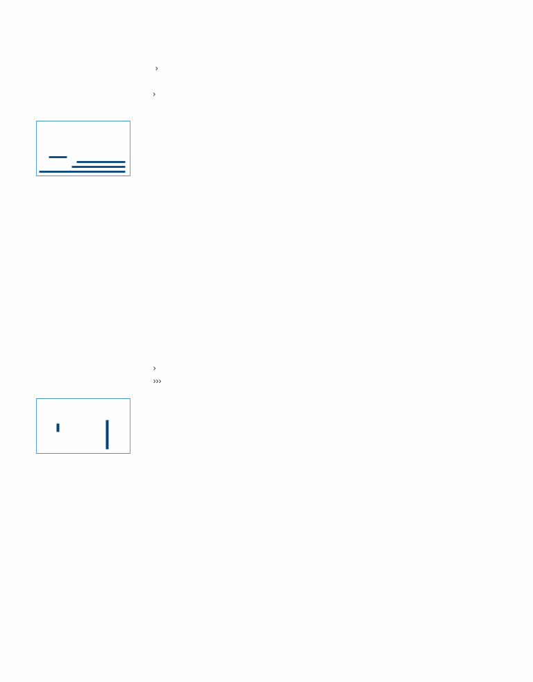
100 Chapter 4: Direct My Eye
A composition primarily made up of horizontal lines implies an overall sense of
peacefulness to an audience. Figure 4.6 shows a cowboy riding his horse across
the flat, open prairie. The horizontal nature of the composition communicates
an uneventful journey to the audience with no visible danger lying ahead for
the character.
Figure 4.6: Horizontal lines convey a sense of stability and calm.
Vertical lines do just the opposite. They convey strength and power. Compared
to horizontal lines, vertical lines are more dynamic, active and tend to dominate
the scene. If we add a cactus to the previous shot, the viewer’s eye would
be attracted to its vertical direction. Vertical lines can also represent walls or
barriers. The cactus is now perceived as an obstacle in the cowboy’s path.
Figure 4.7: Vertical lines convey a sense of strength and power. They are more dynamic and active.
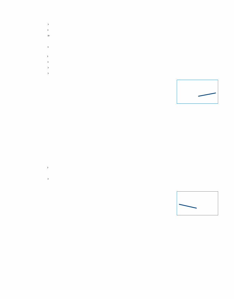
Drawing the Line 101
Diagonal lines imply motion. Static objects arranged in a diagonal composition
appear to move. Tilting a stable horizontal world diagonally evokes a sense of
disorientation and instability. Diagonal lines can be effective in adding tension
to a scene. Compositions comprised mainly of diagonal lines can cause consid-
erable psychological discomfort in the audience.
Tilting the flat horizon diagonally changes the cowboy’s peaceful journey into
an uphill adventure (Figure 4.8). Why? Think about gravity and how it affects
you when you climb a hill or stairs. The diagonal line ascending from left to
right implies a movement that is more physical to follow than a flat, stable line.
Figure 4.8: Diagonal lines evoke a sense of disorientation and instability. They imply a movement that is more physical to follow than a horizontal line.
What if the shot was flipped horizontally? Now the diagonal line is ascending
right to left (Figure 4.9). This makes the journey appear even more difficult. In
addition to fighting gravity, the implied movement created by the diagonal line
goes against how we read from left to right. Our eyes want to travel across the
screen comfortably from left to right. Any element or motion that goes against
this requires more focus and attention.
Figure 4.9: Implied movement goes against how we read an image from left to right.
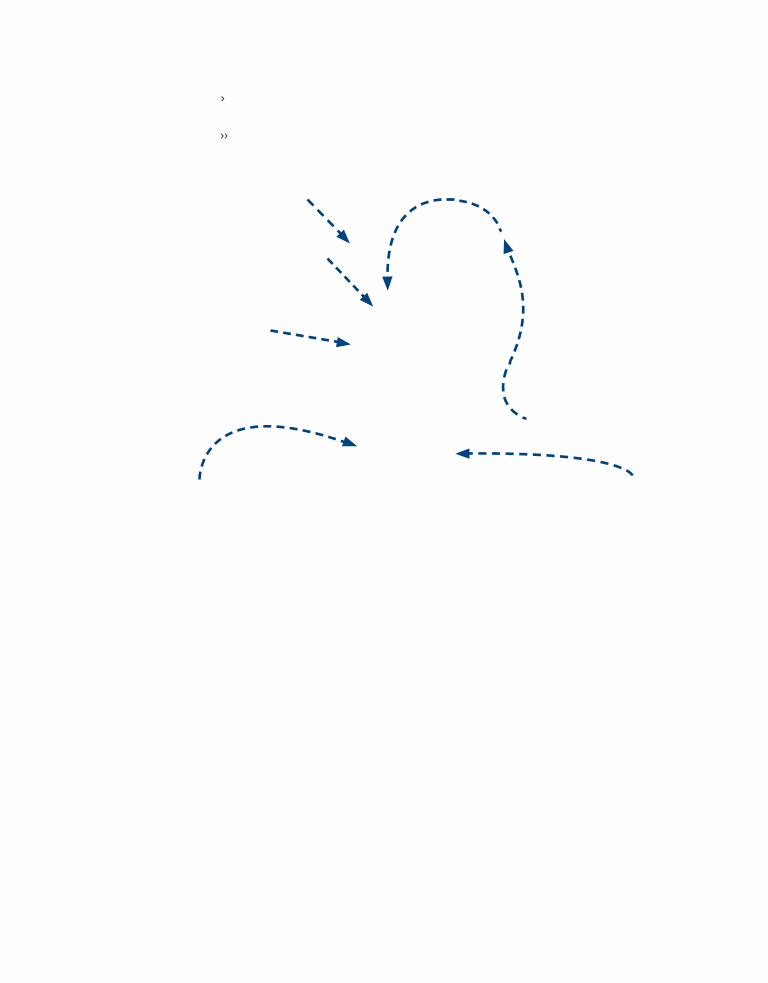
102 Chapter 4: Direct My Eye
Lines provide a visual pathway for the viewer’s eye to follow. However, a line
in a composition does not have to physically be a line. Implied lines come in all
forms. This is often referred to as leading lines in scenes. When designing your
composition, have something lead into the subject from near a bottom corner,
like a road, path, fence, or line of trees to help the eye find the way to the
center of interest (Figure 4.10).
Figure 4.10: Leading lines help the audience find the center of interest.
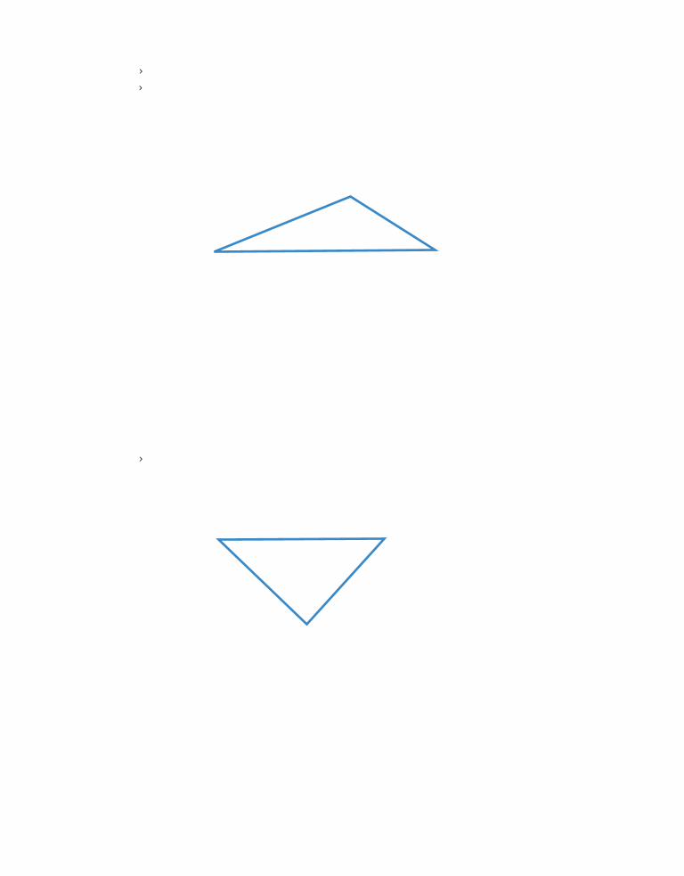
Drawing the Line 103
Lines can also be connected to form shapes such as a triangle. A triangle is
commonly used in compositions to frame action involving characters or objects.
The dynamic nature of a triangle allows the audience to follow around the three
points to create a sense of unity in the composition.
Figure 4.11: Triangular compositions communicate the roles of each character.
A court room scene is a good example of a triangular composition. The judge
is positioned at the height of the triangle’s apex making him superior to the
lawyer and the witness testifying. If the triangle is reversed, with the apex at
the bottom, the character positioned there appears much weaker than the other
two. An interrogation scene in a crime drama is a good example (Figure 4.12).
Figure 4.12: Turning the triangle upside down conveys a different emotional response from the audience.

104 Chapter 4: Direct My Eye
Lines can be curved to create circular compositions. The circle is a universal
symbol signifying completeness, unity, perfection, and eternity. A circular
composition draws the audience deeper into the shot. It provides a more
intimate space for the audience.
Figure 4.13: A circular composition draws the audience deeper into the shot.
No matter how you use lines or shapes, your composition needs to have one
and only one center of interest. The audience needs to be attracted to that one
point. In the previous examples, note the gaze of each character. They do not
look out towards the audience but at the center of interest in the shot. Their
gazes carry our eyes to what is important.
Lines are strong design elements that direct the audience’s attention and imply
dynamic action. However, lines can also be distracting elements in a frame if
used incorrectly. For example, if a line passes through the head of a character,
it seems to cut into the head (Figure 4.14).
Figure 4.14: Avoid using lines that pass directly through a character.

Drawing the Line 105
Overlapping lines are OK, but avoid connecting outlines of one form to
another. The connection made is called a tangent and can be visually confusing
to the eye. It joins the two forms as one when they need to be distinguished as
two separate elements. To fix this, separate your objects or make sure there is
no clear intersection of lines in the shot (Figure 4.15).
Figure 4.15: Tangent lines can create awkward compositions. Try and separate your objects or make sure there is no clear intersection of lines in the composition.

106 Chapter 4: Direct My Eye
Being Dominant
If all the elements in a shot are of equal size or shape, with nothing being
clearly dominant, it becomes very difficult for the audience to know what to
focus on. Often certain elements within a composition seem to leap off the
screen and take visual precedence. Contrasting scale establishes dominance
and creates visual harmony in a composition. In Figure 4.16, the middle cow
is the dominant figure based on its size in the frame. Audiences naturally
seek out the most dominant element in a composition.
Figure 4.16: Contrasting scale establishes dominance in the frame.
Color serves as a dominant element. It can separate one object from others to
attract the audience’s attention. Figure 4.17 illustrates this. In Chapter 1, the
film Schindler List (1993) was referenced for its use of color in visual storytelling.
Steven Spielberg photographed much of the film in black and white. About half
way through the film a girl is shown in a red coat. Spielberg costumed her in
red to visually reinforce her as a dominant element. The audience immediately
focuses its attention due to the contrast in color.
You can also tap into a viewer’s psychological interpretation of color. Your
audience members will have different reactions to different colors. The color
red is a good example; it can be perceived as meaning power, strength, or
passion, but it can also be associated with anger, violence, or danger. Each
color has distinctive emotions attached to it based on the viewer’s
personal experiences.

Being Dominant 107
Figure 4.17: Color establishes dominance in the frame.
Cultures share common opinions about color, for example:
3 Red = hot, power, anger, violence, love, fire
3 Yellow = warm, joyful, sickness
3 Blue = cold, tranquil, peace, water, sadness
3 Orange = courage, cheerful, energy
3 Green = growth, healthy, greed, envy, good luck
Color can be manipulated to reflect the mood of a scene and personality of its
occupants. Figure 4.18 shows a woman standing next to an open door. She is
holding a letter. Even though we cannot read the letter’s content, the use of the
color blue establishes a mood of melancholy. We can deduce through the color
that the letter did not bring good news.
Figure 4.18: The color blue helps establish a mood of melancholy in the scene.

108 Chapter 4: Direct My Eye
Value refers to the lightness and darkness of a color. Contrast between light
and dark can also create compositional dominance in a scene. Every element
within the frame has a specific brightness. By increasing the light in one area or
on a subject you create an area of dominance within a composition. A bright
object or area in a frame gives it extra weight and attracts the viewer’s eye.
On the other hand, areas of darkness can also serve as dominant compositional
elements. The term film noir, French for “black film,” refers to Hollywood
crime dramas popular in the 1940s and ‘50s. Cinematographers in the Film Noir
genre experimented with shadows in their shots. For them, black was the most
important element (Figure 4.19).
Figure 4.19: The film noir genre experimented with dramatic lighting and shadows.
Forms can be very effective in telling a visual story. Having a character in
shadow forces the audience to focus more on the figure’s form, less on the
detail. If the character is gesturing, the resulting silhouetted image clearly
communicates all the visual information the audience needs to know without
losing them to any secondary details (Figure 4.19).
Cinematographers sometimes add forms and shapes to “frame” the focal
point in the composition. This framing device can be anything from a
rectangular doorway or window, to more organic shapes such as a tree branch
that hangs into the shot. Using a frame within the frame breaks up the space
in interesting ways. It also allows the audience to focus on two separate
events in the same frame.

Having Some Depth 109
Figure 4.20: Add forms or shapes to “frame” the focal point in the composition.
In order for the frame to read as a frame, you need to provide enough negative
space between the frame edge and the subject inside the frame. These frames
tend to be positioned in the foreground with the subject matter placed behind
it. In addition to adding more interest to the composition, the resulting image
illustrates a three-dimensional space within a two-dimensional frame.
Having Some Depth
The world around us has three physical dimensions: height, width, and depth.
The images you create in Flash have only two dimensions: height and width.
The illusion of depth can be illustrated within a two-dimensional space. How?
The answer is right in front of us. We start with our perception of depth and the
visual cues found in the real world. Artists throughout the centuries have relied
on their depth perception to vividly construct three-dimensional worlds on two-
dimensional surfaces.
Depth Perception
Take a moment to look at the environment around you. What do you see? You
see a world in three dimensions. Now focus on an object that is close to you.
Your mind tells you how far the object is from you, the space it occupies in front
of or behind something else, and its three-dimensional shape. What makes this

110 Chapter 4: Direct My Eye
incredible is that our eyes are producing only two-dimensional images. It is
the human brain that assembles each image and extrapolates the depth.
This sense of depth is a result of stereoscopic vision (Figure 4.21). Our eyes
are spaced apart, which produces a slightly different image on each retina. To
demonstrate this, hold this book in front of you. Take turns closing one eye.
Notice the difference in what you see from the left eye to the right. Your left
eye will see the left side of the book, while the right eye will reveal the right
side of the book.
Figure 4.21: Stereoscopic vision—each eye produces a slightly different image.
Our brain interprets this retinal difference and then merges the two images
into a single three-dimensional image. The resulting image allows us to perceive
depth and estimate distance. The difference between each retinal image is a
direct result of the depth of the objects that we are looking at—the closer the
object, the greater the difference in each retinal image. Distant objects, such as
mountains, are so far away that our eyes produce essentially the same image,
making depth imperceptible.
Stereoscopic vision isn’t the only way our brain interprets depth. Similar to a
camera lens, our eyes adjust themselves to bring something into focus. Try the
following experiment. Hold your finger in front of you. Position it about six
inches from your face and focus on it. What happens to the objects in the dis-
tance? They are blurry and out of focus. Our brain uses the eye’s focal adjust-
ment to determine the distance of the object from ourselves. We perceive the
finger to be closer to us based on the level of detail our eyes adjusted to.

Having Some Depth 111
We can take advantage of these visual cues when working in a two-dimensional
medium. These include linear perspective, relative image size, interposition,
light and shadows, surface shading, and aerial perspective. Let’s start
with perspective.
Getting into Perspective
Perspective drawings are the most realistic type of representational drawing.
Before illustrating perspective, let’s look at what goes into a 3D drawing.
In order to simulate three dimensions within a 2D world you need four
components. They are:
3 A three-dimensional object
3 A picture plane with a horizon line and vanishing point
3 Projection rays to project the object onto the picture plane’s surface
3 A viewer to observe the object’s image on the picture plane
Figure 4.22: Three dimensional drawings consist of four components.
In perspective, parallel lines that recede into the distance appear to get closer
together. A common image used to illustrate this is a railroad track. The parallel
lines of the track appear to converge at a vanishing point on the horizon.
There are three types of perspective drawings: one-, two-, and three-point
perspective. Let’s look at each in more detail to see how you can apply it to
your compositions.
3D Object projection rays Viewer
picture plane

112 Chapter 4: Direct My Eye
Vanishingpoint 2
Vanishingpoint 1
If one face of an object is parallel to the picture plane, or its horizontal lines and
vertical lines are parallel to the picture plane, the resulting image is a one-point
perspective. There is only one vanishing point on the horizon line. In animation,
one-point perspective is commonly used for roads, railroad tracks, or buildings
and props that directly face the audience.
Figure 4.23: One-point perspective.
If only vertical lines are parallel to the picture plane and no faces of the object
are parallel to the picture plane, the resulting image is a two-point perspective.
This is the most common perspective used in building basic cityscapes or street
scenes in animation.
Figure 4.24: Two-point perspective.
horizon Vanishing point

Having Some Depth 113
If no faces or edges of an object are parallel to the picture plane, the resulting
image is a three-point perspective. This perspective is commonly used for high
or low angle camera shots when the audience is looking at a tall building.
Figure 4.25: Three-point perspective.
Visual Depth Cues
Perspective is a visual depth cue that can be simulated within a two-dimen-
sional world. What other information in our environment allows us to perceive
depth? Another simple visual cue called relative size is easy to reproduce.
The size of each object suggests its relative distance to the viewer. Objects larger
in scale are perceived to be in closer proximity than smaller scaled objects, as
shown in Figure 4.26. Even though this is a flat, two-dimensional image, the
soldier on the left appears closer because of his larger size when compared to
the other soldiers in the scene.
Dramatic manipulation of scale directs the eye to what is important. It can
also help establish the mood in the scene. If a character is small in scale, he may
be perceived as insignificant. Larger objects can convey a feeling of menace,
especially if they overlap other elements in the shot.
Vanishingpoint 1
Vanishingpoint 2
Vanishing point 3

114 Chapter 4: Direct My Eye
Figure 4.26: Relative size—which Roman soldier is closer?
Figure 4.27 demonstrates interposition, or overlapping shapes. All of the
objects are at the same distance from the screen to your eyes, yet the
composition portrays a sense of depth. Overlapping objects assist in creating
this illusion. The red ball is partially blocking the view of the man. It appears
to be closer to the viewer. The cast shadow also helps establish that the
ball’s position is in front of the man. Light and shadows are essential in
creating the illusion of three-dimensional space.
Figure 4.27: Interposition—which object is closer?

Having Some Depth 115
Without these two elements, objects would appear flat. Highlights are a
result of light illuminating or reflecting off an object. Shadows exist where
the light cannot reach. Light and shadows differentiate parts of an object
that are at different depths. Figure 4.28 demonstrates how light and shadows
affect the perception of depth. Both images are the same. The image on the
right has been flipped vertically.
Figure 4.28: Depth perception based on light and shadow.
Notice what happens to the highlights and shadows and how depth is per-
ceived. The raised bumps in the left image become recessed pits in the right
image. Surface shading defines form by giving an object a three-dimensional
feel. In Figure 4.29 the light is coming from the left. The highlights showcase
the light’s angle and define the blue ball’s smooth surface.
The gradient shading across the ball’s surface shows the falloff of light
around the object. It helps illustrate the object’s spherical shape. The illusion
of roundness is achieved through the curvature of the shadows near the
bottom. The cast shadow underneath the ball also helps establish where
the light is coming from.
Figure 4.29: Light and shadows define the surface of the ball.

116 Chapter 4: Direct My Eye
Our atmosphere scatters light, which affects our depth perception. Figure 4.30
simulates this occurrence. Both soldiers are the same size and distance from the
viewer. The right image has been blurred, and the overall coloring is blended
into the background. With these changes, the man on the right appears slightly
farther away than the soldier on the left. This depth change in coloring and
clarity is known as aerial perspective.
Figure 4.30: Aerial perspective—which Roman soldier is closer?
Focusing Attention
In addition to understanding depth cues found in nature, it is important to
understand how a camera lens captures depth. Depth of field is the area in
front of a camera where everything appears sharp and in focus. For example,
if a cinematographer focuses on an actor standing ten feet in front of the
camera, the depth of field can be anywhere from eight to 15 feet. Objects
positioned within this area will be in focus; objects falling outside the area
will be soft and out of focus.
When dealing with 35mm film, a 50mm focal length creates an image that
most closely approximates human sight. Changes in the focal length can
drastically impact the depth perceived in your 3D environment. Wide angle
lenses have much shorter focal lengths and tend to exaggerate depth. Figure
4.31 shows a stretched haunted hallway seen through a 20mm focal length.

Focusing Attention 117
Figure 4.31: Wide angle lenses have much shorter focal lengths and tend to exaggerate depth.
A telephoto lens uses a longer focal length. It does not capture a wide area
of the 3D environment. The perceived depth is reduced considerably. Figure
4.32 shows the same 3D environment seen through a 135mm focal length.
The hallway now looks like a very small, compressed space.
Figure 4.32: Telephoto lenses use a longer focal length and tend to compress depth considerably.

118 Chapter 4: Direct My Eye
Cinematographers use a technique called racking focus to selectively shift the
emphasis from one part of the shot to another. For example, the shot may start
with only the background in focus. As this technique begins, the background
blurs and the foreground comes into focus.
You can employ this cinematic technique to dramatically reveal plot points in
your story. Figure 4.33 shows a man sitting in a chair. Based on his posture,
he appears to be upset about something. Through the use of racking focus
(bottom image) the audience sees what is upsetting the man.
Figure 4.33: Racking focus can dramatically reveal plot points in your story.

Simulating Depth in Flash 119
Simulating Depth in FlashLet’s apply what you have just read about to Flash. Flash provides you with
an assortment of tools and programming code to simulate depth. Both of the
following exercises focus on developing the illusion of three-dimensional worlds
within a two-dimensional environment. Let’s begin.
Locate the Chapter_04 folder on the CD-ROM. Copy this folder to your hard drive. The folder contains all the files needed to complete the chapter exercises.
Exercise 1: Perspective Angles and Vanishing Points
Flash CS4 introduced the ability to position and animate objects in three-
dimensional space. Prior to that, Flash designers simulated depth through
scaling objects. The 3D Rotation Tool and the 3D Translation Tool allow
you to maneuver movie clip symbols in 3D space.
These 3D tools only work on movie clips and no other types of symbols. Also, the 3D capabilities of Flash only work in Flash Player 10 and ActionScript 3.0.
Before you begin using these 3D tools you need to understand the 3D
coordinate system. Similar to any 3D modeling application, Flash divides
its screen coordinate system into three axes (Figure 4.34).
Figure 4.34: The 3D coordinate system in Flash.
3 The x-axis runs horizontally across the Stage with its origin, or 0-point at the left edge of the Stage.
3 The y-axis runs vertically, with its 0-point at the top edge of the Stage.
3 The z-axis runs into and out of the plane of the Stage (toward and away from the viewer), with its 0-point at the plane of the Stage.

120 Chapter 4: Direct My Eye
1. Open the file 01_3DPerspective.fla in the Chapter_04 folder you copied to
your hard drive. It contains all of the files you need to complete this exercise.
There are four layers in the Timeline labeled character, title, guides, and
background. The title on the Stage is a movie clip instance.
2. Select the 3D Rotation Tool (W).
3. Single-click on the title movie clip. A guide for the 3D rotation appears as a
multicolored circular target. Each guide line is color coded: the red line rotates
the movie clip instance along the x-axis, the green line rotates the instance
along the y-axis, and the blue line rotates the instance along the z-axis.
Figure 4.35: A guide for the 3D rotation appears as a multicolored circular target.
4. Experiment with the 3D Rotation Tool. Click on one of the guides and drag
the mouse in either direction to rotate the title movie clip instance in 3D
space. The orange circular guide allows you to freely rotate the instance in
all three directions.
Figure 4.36: The orange circular guide allows you to freely rotate the movie clip.
5. Reset the rotation of the movie clip instance. Open the Transform panel and
click on the Remove Transform button in the lower-right corner (Figure 4.37).

Simulating Depth in Flash 121
Figure 4.37: Remove the 3D transformation using the Transform panel.
You can adjust the Perspective Angle and Vanishing Point properties of the
Flash file. Adjusting the Perspective Angle is similar to zooming in or out of
the Stage. Changing the Vanishing Point position affects the 3D objects’
transformations on the Stage. These settings will only affect the appearance
of movie clip instances that have a 3D transform applied to them. It is also
important to mention that Flash only has one viewpoint, or “camera.”
Each Flash file has one perspective Angle and Vanishing Point setting.
6. Make sure the title movie clip instance is highlighted on the Stage. Go to
the Properties panel. Expand the 3D Position and View section. The default
location of the Vanishing Point is the center of the Stage. The guides layer
shows where the vanishing point would be in this scene. Adjust the vanishing
point to match. In the Properties panel:
3 Click-and-drag the X value of the Vanishing Point setting to -515.0 to move the vanishing point indicated on the Stage by intersecting gray lines.
3 The background image’s horizon line is above the horizontal center of the Stage. Click-and-drag the Y value of the Vanishing Point setting to 35.0 to change the vertical position of the vanishing point.
Figure 4.38: Adjust the vanishing point’s X and Y positions to match the guides layer.

122 Chapter 4: Direct My Eye
7. Using the 3D Rotation Tool, click on the y-axis (green line) and rotate the title
to fit comfortably on the brick wall. Notice that by repositioning the vanishing
point the title matches the drawn perspective in the scene better.
Figure 4.39: Rotate the title along the y-axis.
8. Go to the Properties panel, and change the Perspective Angle to zoom in
or out of the Stage.
Figure 4.40: Adjust the perspective angle to zoom in and zoom out.
9. In the Filters section, click on the Add Filter icon at the bottom of the Properties
panel. Add a drop shadow to the title movie clip instance. Increase the amount
of blur in the drop shadow by changing the Blur X and Y directions to 15 pixels.
Figure 4.41: Add a drop shadow to the title.

Simulating Depth in Flash 123
10. Save your file. Select Control > Test Movie to see the final results. To see a
completed version of this exercise, open 01_3DPerspective _Complete.fla
in the Completed folder inside the Chapter_04 folder.
Figure 4.42: Save and test your movie to see the final results.
Exercise 2: Racking Focus Using the Blur Filter
This exercise will simulate racking focus using the Blur filter in Flash. To review,
cinematographers use racking focus to selectively shift the emphasis from one
part of the shot to another. In this exercise, the animation starts with only the
background in focus. As the rack focus begins, the background blurs and the
foreground comes into focus.
1. Open the file 02_RackFocus.fla in the Chapter_04 folder you copied to your
hard drive. It contains all of the files you need to complete this exercise. There
are two layers in the Timeline labeled foreground and background. Each object
on the Stage is a movie clip instance.
2. Select the foreground movie clip instance. Go to the Properties panel.
3. In the Filters section, click on the Add Filter icon at the bottom of the Properties
panel. Select Blur from the drop-down menu. Make sure that the Blur X and Y
factors are set to 5. Set the Quality to High.

124 Chapter 4: Direct My Eye
Figure 4.43: Apply a Blur filter to the foreground movie clip instance.
4. Click on the empty cell in frame 20 on the foreground layer.
5. Select Insert > Timeline > Keyframe or press the keyboard shortcut of F6
to generate a new keyframe.
6. With the foreground still selected on frame 20 go to the Properties panel
and reduce the Blur X and Y factors to 0.
7. Add a tween to the foreground layer by right-clicking on the gray area
in between the two keyframes and selecting Create Classic Tween.
Figure 4.44: Apply a tween to animate the blur filter.
8. Save your file. Select Control > Test Movie to see the animation. The
foreground slowly comes into focus. You are halfway there. Now you
need to blur the background.
9. Click on the empty cell in frame 20 on the background layer.
10. Select Insert > Timeline > Keyframe or press F6 to generate a new keyframe.

Simulating Depth in Flash 125
11. With the background movie clip instance still selected on frame 20 go to
the Properties panel.
3 In the Filters section, click on the Add Filter icon at the bottom of the Properties panel.
3 Select Blur from the drop-down menu.
3 Increase the amount of blur by changing the Blur X and Y factors to 7.
3 Set the Quality to High.
Figure 4.45: Apply a Blur filter to the background movie clip instance.
12. Add a tween to the background layer by right-clicking on the gray area
in between the two keyframes and selecting Create Classic Tween.
13. Save your file. Select Control > Test Movie to see the animation. To see a
completed version of this exercise, open 04_ RackFocus _complete.fla in the
Completed folder inside the Chapter_04 folder.
Figure 4.46: Save and test your movie to see the final results.

126 Chapter 4: Direct My Eye
Summary This chapter focused on composition. Composition is the structure behind
your shot. Its function is to direct the audience’s attention to what is happening
in the scene. Key points to remember from this chapter include:
3 Compositions need to have one and only one center of interest.
3 Design elements such as line, shape, color, and value are used together to form a composition.
3 Lines direct the audience’s attention and imply dynamic action.
3 Color can be manipulated to reflect the mood of a scene and personality of its occupants.
3 Visual depth cues include linear perspective, relative image size, interposition, light and shadows, and aerial perspective.
3 Depth of field is the area in front of a camera where everything appears sharp and in focus.
3 Cinematographers use racking focus to selectively shift the emphasis from one part of the shot to another.
Flash provides you with an assortment of tools to simulate depth.
3 The 3D Rotation Tool and the 3D Translation Tool allow you to maneuver movie clip symbols in 3D space.
3 Adjusting the Perspective Angle is similar to zooming in or out of the Stage.
3 Changing the Vanishing Point position affects the 3D objects’ transformations on the Stage.
3 Flash offers filters that can be applied to symbol instances. These filters include Drop Shadow, Blur, Glow, and Bevel.
Understanding composition works well for individual shots, but you also have
to deal with an additional element: time. An animation consists of a sequence of
shots that manipulate both space and time. The next chapter focuses on editing
shots together into narrative order. The magic of editing is that it can help build
on the dramatic tension created from each shot’s composition.

Chapter 5
Don’t Lose Me
In film, an editor stitches together various camera
shots to create a seamless sequence of events that
appear to take place in a certain space for a certain
amount of time. This is a cinematic illusion created
by carefully planned camera shots and editing.
2 Manipulating Time and Space ........................................ 128
2 Understanding Screen Direction ..................................... 130
2 Using the 180-Degree Rule .............................................131
2 Cutting and Continuity ....................................................142
2 Transitioning Scenes ....................................................... 146
2 Building Transitions in Flash ............................................ 149
©2010 Elsevier Inc. All rights reserved. DOI: 10.1016/B978-0-240-81261-8.50005-2

128 Chapter 5: Don’t Lose Me
Manipulating Time and Space In Chapters 3 and 4, we studied how cinematographers manipulate the space
perceived in a shot. Through clever camera positions, angles, and composition
they can create almost any spatial relationship between the elements in the
shot. What about time?
Think about it; most movies that you watch take place over the course of a few
days, or weeks, or even years. You, as an audience member, see a compressed
timeline of the events that transpire. The events shown are essential to drive
the narrative forward and condense the actual running time.
So how do you condense time? Figure 5.1 illustrates the first three shots for
an animation of a boy painting a fence. Similar to a story’s three act structure,
a scene can achieve visual continuity using three basic shots: the long shot, the
medium shot, and the close-up. Let’s deconstruct the sequence of shots as
shown in Figure 5.1.
Figure 5.1: Time can be manipulated using a series of camera shots and editing.

Manipulating Time and Space 129
The opening shot is a long shot that establishes the boy and the fence he has
to paint. The next shot is a medium shot showing the boy starting the job. A
close-up reveals the boy’s determination to finish. The animation contincues
with another close-up showing the paintbrush applying the paint, but does not
show too much of the fence. Finally, the animation concludes the scene with
the same opening long shot, and shows that the painting is almost complete.
A two-hour job has been condensed into a 20-second animation. Had the
animation been shown in real time, it would have been about as exciting as
watching the paint dry. With that being said, time can also be expanded to add
tension or drama to a scene. Locate and open the file 01_ExpandedTime.swf
inside the Examples folder in Chapter_05.
Figure 5.2: Editing can expand time to add tension or drama to a scene.
In this scene, the villain falls off a cliff of a tall mountain. The actual event may
only take a few seconds for the character to hit the ground. Clearly this is too
short of a time to portray because it cheats the audience in seeing the villain
get what he deserves. Instead the animation inserts close-ups of his facial
reactions, his clutching hands, his kicking feet, and the background whirling
past him as he freefalls (Figure 5.2).
All of these shots create an expansion in time. The audience doesn’t care
because they are caught up in the visual storytelling. So, you can see that it is
possible to manipulate time through breaking up long scenes into several shots.
This makes the story more interesting for the audience. It also allows you to edit
the length of each shot too add emphasis to the story where you desire.

130 Chapter 5: Don’t Lose Me
Editors achieve this cinematic illusion by editing the movie together after the
film has been shot. As a Flash designer, you don’t have that luxury. You need
to do all of your editing during the storyboard stage. The goal is to establish
continuity from shot to shot. Continuity can be achieved by understanding
screen direction, applying the 180-degree rule, and the proper use of cuts.
Understanding Screen DirectionScreen direction refers to the direction of movement, or the direction a
character is facing within the frame. Too many shots filmed from too many
different camera angles can create problems with continuity in screen direction.
If a character’s position moves forward in one shot and then changes to a move
backwards in the next shot, the continuity of the picture is disrupted and the
audience is confused (Figure 5.3). Note the skyline in relation to the superhero.
Figure 5.3: The continuity is disrupted from one shot to the next causing confusion for the audience.
It is important to understand how a frame transposes our world in two-
dimensional space. If a character facing the camera moves to the right, he
actually moves toward the left edge of the frame, or screen left. If the
character moves to the left, he moves screen right (Figure 5.4). It may seem
confusing at first, but the rules of screen direction not only help maintain
continuity but also the audience’s perception of the space they are viewing.
All screen movement should be mapped out in the storyboard before
production begins. If a character’s screen movements are not planned out
properly, the resulting scenes may be a mix of right-to-left and left-to-right
opposing movements, which jeopardizes continuity. What about having two
or more people in the shot?

Using the 180-Degree Rule 131
Figure 5.4: Screen direction refers to the direction of movement on the Stage.
Using the 180-Degree RuleA scene showing two people having dinner in a restaurant might consist of
three basic shots: a medium shot showing both of them seated at the table and
two close-ups, one for each person. These shots orient the viewer to the space
and how the characters occupy it. In order to shoot the scene and edit each
shot together effectively it is important to understand the 180-degree rule.
Figure 5.5 illiustrates three shots from an animated scene of a conversation
between two characters. Notice that something is awkward about the editing
of the shots. The second shot of the woman changes in screen direction. She
appears to be talking to the back of the man’s head. This is called reversed
screen direction. The line of action has been crossed creating an error in
continuity. What is the line of action?
The line of action is an imaginary line that determines the direction your
characters and objects face when viewed through your virtual Flash
“camera.” When you cross the line of action, you reverse the screen direction
of everything captured through the camera, even though the characters or
object have not moved an inch.
Screen Left
Screen right

132 Chapter 5: Don’t Lose Me
Figure 5.5: The reversed screen direction in Shot 2 causes an error in continuity.
Figure 5.6: Choose camera shots on one side of the 180-degree line.
180°
top View
Shot 1
Shot 2 Shot 3

Using the 180-Degree Rule 133
Figure 5.6 illustrates this concept using the two characters seen from an
overhead view. The imaginary line runs through both characters’ heads. Its
direction is based on how each character faces one another. The primary
rule is to pick one side of the line and stay on it throughout the scene. This
is called the 180-degree rule.
As long as the camera stays on the front side of the line, the man will be
looking screen left and the woman will be looking screen right. If you cross
the line, they’ll be looking in the opposite directions, although they haven’t
moved at all. You can choose from a variety of camera shots and angles as
long as you stay on one side of the 180-degree line.
Note the matching eye lines (Figure 5.7). When using the line of action, the
characters’ eye line also needs to match from one shot to another. In this
example the man is slightly taller than the woman. His downward glance is
matched by her eyes looking up from shot to shot.
Figure 5.7: Match the eye lines when editing shots of two people interacting with one another.
Locate and open the file 02_LineofAction.swf inside the Examples folder
in Chapter_05. Click on the different cameras to see how they frame the
characters. A mismatch in continuity is achieved by clicking on camera 4.
Figure 5.6 illustrates the crossing of the line of action.
Is there a way to cross the line and still have continuity? Do you always
have to follow this rule? Similar to the Rule of Thirds discussed in Chapter 4,
the 180-degree rule is only a guideline for maintaining continuity. There may
be circumstances in which you want to cross the line. There are a couple of
ways to achieve this without confusing the audience. Let’s take a look at
how to break the 180-degree rule.

134 Chapter 5: Don’t Lose Me
Breaking the Rule
The easiest way to break the 180-degree rule is to have your subject change
screen direction on camera, within the frame. For example, Figure 5. 8 shows
a character physically turn around to face another character in the opposite
direction. As long as the change in screen direction is made on camera, there
is no confusion.
Figure 5.8: You can maintain continuity by changing a character’s screen direction.
Another method is to cross the line using one continuous move with the
camera. Figure 5.9 shows a robber trying to break into a safe. The initial
camera position blocks his actions. To show the audience what he’s doing, the
camera moves from his left side, behind his back, to the right side. The camera
movement transports the audience to a new angle without any disorientation.
In film, a car chase scene typically breaks the 180-degree rule. Locate and open
the file 03_CarChase.mov inside the Examples folder in Chapter_05. The chase
scene is set up left to right along the line of action. The bank robber’s point of
view (POV) in the second shot reinforces the left to right line of action. In order
to show the police officer’s POV, the 180-degree rule must be broken.
Using the 180-Degree Rule 135
Figure 5.9: You can maintain continuity by repositioning the camera using one continuous movement.
A neutral shot of the robber’s car is shown in the third shot (Figure 5.10). The
camera is placed on the line of action. Neutral shots are head-on shots of a
subject, with no evident screen direction. By inserting this neutral shot between
the robber’s POV and the officer’s POV taken from the opposite side of the line
of action, you can change screen direction and still retain continuity.
Figure 5.10: A neutral camera angle allows you to cross the line of action.
top View

136 Chapter 5: Don’t Lose Me
When a shot is completely framed from the character’s point of view it is called
a subjective shot. The camera is perceived to be inside the character’s head. The
audience sees what the character sees. In the opening scene of John Carpenter’s
film Halloween (1978), the audience looks through the eyes of the killer. This
intensifies the audience’s fear by participating in the on-screen action.
Subjective shots can be great for establishing not only what a character sees
but how it sees. As you read in Chapter 4, applying a simple blur effect creates
an out-of-focus shot. When combined with a subjective shot, you can achieve
a feeling of a character slipping out of consciousness (Figure 5.11).
Figure 5.11: Subjective shots establish not only what the character sees but how it sees.
Building a Sequence
One common mistake used in Flash animation is to contain all of the action
to one shot. To convey a story in an interesting manner, you need a series of
shots joined together; each shot being continuous like in a stage play. During
postproduction on a film, an editor selects, cuts, and arranges various shots
into narrative order. An editor must determine:
3 Which shots to use
3 What order to put them into
3 How long each shot will last on screen
Most visual storytelling can be done in animation using a combination of three
basic shots. Chapter 3 discussed each shot and what it conveys to the audience.
To review, a long shot shows where the action takes place. A medium shot is

Using the 180-Degree Rule 137
used to focus on a specific character and his or her actions. A close-up is used
for character’s speaking or showing the action in detail. Choosing the wrong
shot can ruin a scene.
Equally important to a shot’s image is the order in which it is placed. This is
often referred to as continuity editing. The action is generally presented in a
logical, chronological sequence. Placing shots before or after other shots can
create totally different meanings for the audience.
For example, Figure 5.12 shows two images in a sequence. The left image
shows a forest fire and the right image shows a man running away. If the
sequence is read from left to right, the audience sees that the man escaped
from the fire. What if the sequence is reversed? Now the audience thinks
that the man running away is responsible for the forest fire (Figure 5.13).
Figure 5.12: Continuity editing presents each shot in a chronological sequence.
Figure 5.13: Reversing the sequence of shots can create a totally different story.

138 Chapter 5: Don’t Lose Me
What about a shot’s duration? That depends on the type of story you are telling.
The rhythm of a scene is determined by the length and frequency of its shots
and the movement within each shot. Watch any chase scene in a movie. These
scenes start with a slow build-up with long establishing shots. As the chase
reaches its climax, the shots get shorter and shorter in duration. They are
presented to the audience in rapid succession to intensify the action.
Horror movies build suspense through skillful editing. A typical horror movie
sequence starts with a series of tight close-ups revealing a character’s anxiety.
This is followed by a long continuous shot of the character walking down a
dark path. The deliberately slow pacing heightens the audience’s anticipation
of what is to come next.
Suddenly a quick cut jolts the audience right out of their seats. Usually it is
a shot of a cat jumping out of the shadows. This is followed by slow reaction
shots of the character laughing over the situation. The slower pace relaxes
the audience allowing them to catch their breath. Just when the audience
thinks they are safe, another explosion of quick cuts occurs as the sequence
reaches its climax.
Figure 5.14: Horror movies build suspense through skillful editing.
In Alfred Hitchcock’s film, Psycho (1960), a woman is brutally murdered in
the shower. Hitchcock used a combination of close-up and extreme close-up
shots with short durations. The rapid editing of this sequence implies a more

Using the 180-Degree Rule 139
uncontrolled violent death, even though the knife is never shown piercing the
body. The subjective camera angles place the audience inside the shower and
the rhythmic editing of shots mirrors the killer stabbing the victim.
Building Sequences in Flash
So how do you build a sequence in Flash? One possible solution is to organize
your entire animation into separate scenes. Sound familiar? Flash has adopted
the filmmaking concept of a scene that allows you to build smaller, more
manageable sections of your movie in one document. When you create a new
Flash file you are given one scene to work in. Scene 1 is indicated by the small
clapboard icon underneath the Timeline (5.15).
Figure 5.15: Scenes in Flash allow you to build smaller, more manageable sections for your movie.
To add a new scene, simply select Insert > Scene. Flash creates a new, empty
scene labeled Scene 2. You can add as many scenes as you want. To manage
all of the scenes in a Flash file, open the Scene panel by selecting Window >
Other Panels > Scene (Figure 5.16). In this panel you can rename each scene
by double-clicking on the name.
Figure 5.16: The Scene panel is a management tool for all scenes in the Flash file.
Flash will play back each scene in order from top to bottom as listed in the
Scene panel. Once the playhead reaches the last frame of one scene, it
automatically jumps to the first frame in the next scene. To rearrange the

140 Chapter 5: Don’t Lose Me
scene sequence, click and drag a scene to reposition it in the list. A bright green
horizontal line appears to indicate where the scene will be positioned after you
release the mouse.
Locate and open the file 04_TheDuel_Scenes.fla inside the Examples folder in
Chapter_05. Select Control > Test Movie to see the animation. The Flash file
is made up of several scenes. To access each scene’s separate Timeline single-
click on a scene name in the Scene panel or select a scene from the drop-down
menu located at the bottom right corner of the Timeline. This technique is great
for short animated films under two minutes in duration.
Figure 5.17: To quickly access each scene’s Timeline select a scene from the drop-down menu.
Is using scenes in Flash the only way to build a sequence? Absolutely not.
Locate and open the file 05_TheDuel_GraphicSymbols.fla inside the Examples
folder in Chapter_05. Select Control > Test Movie to see the animation. It is
visually the same story as in the previous example. The difference is in how
the animation was built.
Instead of using separate scenes in Flash, each shot was nested inside a graphic
symbol. The graphic symbols are strung together on the main Timeline in

Using the 180-Degree Rule 141
chronological order. Scrub the playback head back and forth to see the nested
animation play. This technique is good for quick 30-second animated shorts,
web banners, or online commercials.
Figure 5.18: Flash animators often place an entire animation inside a graphic symbol’s Timeline.
Both methods are perfectly acceptable to use when building more complex
animated films in Flash. The only disadvantage is a potentially large file size,
since all of the assets are included in the one file. If file size is a concern, try
breaking up your sequence into smaller, separate Flash FLA files. ActionScript
can be used to play each published SWF file in chorological order. Chapter 9
covers interactivity in more detail. Even though Flash can store multiple scenes
in one large movie, having smaller individual files provides easier editing
capabilities, especially when exporting to After Effects. It also reduces the risk
of file corruption that could occur using extremely long Timelines.
Figure 5.19: Sometimes it is better to break scenes from a large Flash animation into separate FLA files and then load the published SWF files dynamically.

142 Chapter 5: Don’t Lose Me
No matter how you choose to build your animation in Flash, you must maintain
continuity when sequencing shots together. Movement should flow smoothly
and seamlessly from one shot to another. A good editor can assemble a scene
without the audience noticing the individual shots. To them the scene is one
continuous sequence that takes place in one certain space at a certain time.
Cutting and Continuity
A cut is one shot that allows you to easily change the length and/or order of
the scene. Cutaways serve to enhance the story. Any shot can act as a cutaway,
as long as it relates to and reinforces the main action. The goal in editing a
scene is that you want the audience to presume that time and space has been
uninterrupted. So how do you cut and still preserve continuity?
Figure 5.20 shows a female character speaking to a crowd. Rather than have
the audience sit through her entire speech, another shot is inserted to show the
crowd’s reaction. With the cutaway of the spectators established, you can now
cut back to the speaker at any point in her speech and in effect, condense time.
Figure 5.20: The cutaway reaction shot (right) can help condense the story’s time.
This type of cutaway shot is commonly used in television interviews to show
the reporter listening to the interviewee. A cut doesn’t always have to show
a reaction shot. Review the example of the boy painting the fence from the
beginning of this chapter.
Each cut reinforces the progression in the action. The shots do not show every
detail in painting a fence. That would take too long and the audience would
become bored. The editing and cutting compress time into smaller shots that
assist in moving the action along at a faster pace.

Cutting and Continuity 143
Relational Cutting
Another editing technique is called relational cutting. This type of cut brings
together two shots that have no direct connection. If you cut from a long shot
showing an airplane in flight to a medium shot of a pilot sitting in a cockpit,
you have established for the audience a relationship between the two shots.
Relational cutting works well between relatively static shots.
Cutting on the Action
As previously mentioned, the rhythm of a scene can also be affected by
the movement within each shot. A good way to achieve a smooth transition
between shots is to cut on the action. Audiences will naturally follow
movement on the screen. If a movement begins in one shot and ends in
the next, the viewer’s eye will follow along without becoming disoriented.
For example, Figure 5.21 shows a man picking up a cup of coffee to drink.
The scene consists of two camera shots. The first shot is a medium shot
showing the action of the man lifting the cup. The second shot is a close-up
showing the cup being raised to man’s mouth. Even though the camera
distance changed, the physical movement of lifting the cup is continuous.
The man’s movement in the second shot begins where it ended in the first
shot. In editing, this is called a match cut.
Figure 5.21: A match cut maintains continuity in movement from shot to shot.
A match cut helps maintain continuity by carrying the viewer’s eye smoothly
from one shot to the next. Almost any kind of movement from opening a
door to sitting down can be effectively shown using a match cut. In fact, it does
not need to involve a large motion. A slight turn of the head or a small hand
gesture will work. Match cuts can also be used to tell the story metaphorically.

144 Chapter 5: Don’t Lose Me
A famous match cut is in Stanley Kubrick’s 2001: A Space Odyssey (1968).
In the beginning of the film, a primitive ape throws a bone into the air after
using it as a weapon. When the bone reaches its highest point the shot cuts
to a similarly-shaped spaceship which also turns out to be a weapon of the
future. This cut compositionally matches the shapes and movement between
shots and creates a metaphorical connection between primitive and advanced
tools of destruction.
Clean Entrances and Exits
If a character is featured in two successive shots in different locations, the cut
needs to have a clean entrance and exit. If you just cut between the two shots,
the change in backgrounds will be noticeable and confusing. The audience
didn’t see how the character got there.
Locate and open the file 06_CleanEntranceExit.swf inside the Examples folder
in the Chapter_05 folder on the accompanying CD-ROM. This simple anima-
tion shows the cyclist exit the frame in the second shot. It holds the empty
frame for a second or two. Then shows the second background location empty
before the cyclist enters the frame. By not seeing the character on screen for a
second or two, the audience will accept that he had time to travel to the
different location in the following shot.
Figure 5.22: Have your characters make a clean entrance and exit.
If you ever watch a play, you will notice that the actors make a clean entrance
and exit on the stage. They don’t suddenly appear out of thin air. Apply this
technique to your animation. Clean entrances and exits work well for shots
where someone is moving from one place to another, picking something up, or
putting something down. It eliminates awkward shifts in time and allows the
audience to focus on the action without being surprised or disoriented.
Jump Cuts
A jump cut is an abrupt transition from one shot to another. This type of cut is
used sparingly to build suspense. One type of jump cut is called a cut-in and
is used to focus the audience’s attention immediately on the action. The cut-in

Cutting and Continuity 145
shot narrows the audience’s view point in the scene. This is accomplished by us-
ing a close-up shot of something already within the frame. A good film example
occurs in Alfred Hitchcock’s The Birds (1963). In the film, Hitchcock slowly
reveals the body of a dead farmer, and then shocks the audience by cutting in
with three quick jump cuts to show that the corpse’s eyes were gouged out.
The horrific triple cut first shows a long shot of the farmer’s bloodied body, then
a medium shot cuts in tighter to frame the body from the waist up, and finally
a horrific close-up shot reveals the missing eyes. Rather than using a cut away
or a zoom in, Hitchcock choose to use jump cuts to visually push the audience
closer and add shock value to the scene.
Crosscutting
So far we have looked at cutting techniques for action that is occurring within
the same space. This is called continuity editing. Crosscutting, also called
parallel editing, cuts back and forth between events happening in different
locations. A common example of crosscutting is a phone conversation. Two
characters are shown on their phone in their location. The back and forth
editing implies that the two events are occurring simultaneously.
Figure 5.23: Crosscutting cuts back and forth between different locations.
A classic film example of crosscutting happens in the Perils of Pauline, a silent
film episodic serial from 1914. In the film, the villain ties the heroine to the
railroad tracks as a train approaches. The audience’s attention is switched back
and forth to show the oncoming train, the woman struggling to free herself,
and the hero coming to her rescue (Figure 5.23).

146 Chapter 5: Don’t Lose Me
This editing technique works well for action films because it builds on the
tension in the scene. The audience is on the edge of their seats in anticipation.
Will the hero make it in time to rescue Pauline?
Crosscutting can be effectively used to contrast the action occurring in the story.
In Francis Ford Coppola’s film The Godfather (1972), the baptism of Michael
Corleone’s (played by actor Al Pacino) godchild in church is crosscut with scenes
of Corleone’s enemies being murdered by his hired men. This memorable
sequence uses the editing to symbolically reflect Michael Corleone’s double life
he leads as head of the mafia family.
Transitioning ScenesIn addition to cuts, there are other methods you can use to transition from
one scene or shot to another. A fade is a common transition used in early
filmmaking at the start and end of every sequence. A fade increases or
decreases the overall value of the scene into one color. For example, a fade
to black typically indicates the end of the scene.
One scene can fade out as another scene fades in. This is called a dissolve
and is used frequently to indicate the passage of time. For example, let’s create
a medium shot of a little girl standing along the side of the road. Then the
shot dissolves to an extreme long shot to imply that she has been waiting for
a long time (Figure 5.24).
Dissolves are also used effectively in film to show a character age or turn into a
monster right before the viewer’s eyes. Watch any classic monster movie from
the mid to late 1940s. In Abbott and Costello Meet Frankenstein (1948), actor
Lon Chaney Jr. is shown transforming into the Wolfman using clever makeup
and camera dissolves. The dissolve transformation on screen only took seconds,
while Chaney’s makeup took almost ten hours.
Figure 5.24: Dissolves convey the passage of time.

Transitioning Scenes 147
A wipe transition is visually apparent to the audience and clearly marks the
change. One scene wipes across the frame and replaces the previous scene.
Wipes can move in any direction and open from one side to the other, or they
can start in the center and move out, or the edge of the frame and move in.
Contemporary film examples include George Lucas’ Star Wars films which
incorporate a sweeping use of wipes that pay homage to the pulp sci-fi
serials of the 1930s and ‘40s.
Figure 5.25: Wipes can move in any direction to reveal the next shot.
The Looney Tunes and Merrie Melodies cartoon series employed an iris wipe
to signify the end of the story. This type of wipe consists of a growing or
shrinking circle that reveals the next shot in the scene. The iris wipe can center
on the focal point or be used to highlight an inside joke for the audience. For
example, the iris wipe can shrink down to the character winking at the audience.
This type of action is referred to as “breaking the fourth wall.” The character is
recognizing the audience watching.
Figure 5.26: An iris wipe can center on the focal point or be used to highlight an inside joke for the audience.
Wipes can be cleverly hidden by the movement on the screen. In the movie
Jaws (1975), director Steven Spielberg shows the sheriff (played by actor Roy
Scheider) sitting on the beach. Another actor walks directly in front of the

148 Chapter 5: Don’t Lose Me
camera obscuring the audience’s view. When the actor walks by, the audience
sees a new camera position (Figure 5.27). The editor uses the movement on
screen as an invisible wipe without the audience noticing.
Figure 5.27: An invisible wipe incorporates a character’s movement in the frame as a transitional element.
Montages
A montage is a series of related shots. Most television commercials and music
videos contain montages. For a montage to work effectively, each shot in the
sequence needs to be different in composition and show a different subject.
Otherwise, the end result will look like a bad cut between two similar shots
of the same thing.
Action movies from the mid to late 1980s always incorporated a montage of
the hero preparing for battle. Watch any Arnold Schwarzenegger film such
as Commando (1985) or the opening scenes in Joel Schumacher’s Batman
Forever (1995). Film historians often reference a famous montage from the
silent, propaganda film Battleship Potemkin (1925). The montage portrays
the massacre of civilians on the Odessa Steps showing shots of soldiers
marching, a baby carriage rolling down the flight of steps, and a woman
with a bloody eye screaming.

Building Transitions in Flash 149
Building Transitions in FlashLet’s take a look at building the different types of transitions you just read
about in Flash. The exercises that follow offer two distinct methods. In the
first method the transitions are created on the Flash Timeline using masked
layers and tweened animation to achieve the effect. The second approach
uses ActionScript, specifically the TransitionManager class, to define the
animation effect through code.
Locate the Chapter_05 folder on the CD-ROM. Copy this folder to your hard drive. The folder contains all the files needed to complete the chapter exercises.
Exercise 1: Fade From Black
Let’s begin by building the classic fade transition used quite often in early
silent movies. Creating fades in Flash is quite simple and only involves just
a handful of steps.
1. Open the file 01_FadeFromBlack.fla in the Chapter_05 folder you copied to
your hard drive. It contains all of the artwork you need to complete this exercise.
There are two layers in the Timeline labeled fade and artwork. Each object on
the Stage is a graphic symbol instance.
2. Click on the empty cell in frame 10 on the fade layer.
3 Select Insert > Timeline > Keyframe or press the keyboard shortcut F6 to generate a new keyframe.
3. Click on the empty cell in frame 24 on the fade layer and create a keyframe.
4. Click on the empty cell in frame 60 on the artwork layer.
3 Select Insert > Timeline > Frame or press the keyboard shortcut of F5.
Figure 5.28: Set up the keyframes for each layer.
5. Select the keyframe on frame 24 of the fade layer. Click on the instance
on the Stage. Go to the Properties panel.
3 Select Alpha as the Style from the Color Effect options.
3 Adjust the Alpha setting to 0%. Visually, the graphic instance disappears on the Stage revealing the artwork layer.

150 Chapter 5: Don’t Lose Me
6. Add a tween to the fade layer by right-clicking on the gray area in between the
two keyframes from frame 10 to frame 24 and selecting Create Classic Tween.
Figure 5.29: Change the alpha color effect for the graphic symbol and apply a tween.
7. Save your file. Select Control > Test Movie to see the animation. The black
rectangular shape slowly fades away to reveal the art. To see a completed
version of this exercise, open 01_ FadeFromBlack _Complete.fla in the
Completed folder inside the Chapter_05 folder.
Figure 5.30: Save and test your movie to see the final results.

Building Transitions in Flash 151
Exercise 2: Dissolve
Creating a dissolve in Flash is very similar to the first exercise. Instead
of tweening the alpha property of a black rectangle, you use another
symbol instance. Let’s take a quick look.
1. Open the file 02_Dissolve.fla in the Chapter_05 folder you copied to your
hard drive. It contains all of the artwork you need to complete this exercise.
There are two layers in the Timeline labeled shot1 and shot2. Each object on
the Stage is a graphic symbol instance.
2. Click on the empty cell in frame 10 on the shot 1 layer.
3 Select Insert > Timeline > Keyframe or press the keyboard shortcut F6 to generate a new keyframe.
3. Click on the empty cell in frame 24 on the shot 1 layer and create
another keyframe.
4. Click on the empty cell in frame 60 on the shot 2 layer.
3 Select Insert > Timeline > Frame or press the keyboard shortcut of F5.
5. Select the keyframe on frame 24 of the shot 1 layer. Click on the instance
on the Stage. Go to the Properties panel.
3 Select Alpha as the Style from the Color Effect options.
3 Adjust the Alpha setting to 0%. Visually, the graphic instance disappears on the Stage revealing the shot 2 layer.
6. Add a tween to the shot 1 layer by right-clicking on the gray area in
between the two keyframes from frame 10 to frame 24 and selecting
Create Classic Tween.
Figure 5.31: Change the alpha color effect for the graphic symbol and apply a tween.
7. Save your file. Select Control > Test Movie to see the animation. The first
image slowly fades away to reveal the art. To see a completed version of this
exercise, open 02_ Dissolve _Complete.fla in the Completed folder inside
the Chapter_05 folder.

152 Chapter 5: Don’t Lose Me
Exercise 3: Wipes
To create a wipe transition in Flash, you use an animated masked layer. To
create a mask, you specify that a layer is a Mask layer, and draw a filled
shape on that layer. The mask layer reveals the area of linked layers beneath
the filled shape.
1. Open the file 03_Wipe.fla in the Chapter_05 folder you copied to your hard
drive. It contains all of the artwork you need to complete this exercise. There
are three layers in the Timeline labeled mask, shot2 and shot1. Each object on
the Stage is a graphic symbol instance.
2. Notice that the graphic instance of the mask symbol is positioned off the left
hand side of the Stage. Click on the empty cell in frame 20 on the mask layer.
3 Select Insert > Timeline > Keyframe or press F6.
3. Click on the empty cell in frame 60 on the mask layer and create
another keyframe. On frame 60:
3 Click and drag the mask symbol instance on the Stage.
3 Center it over the visible artwork.
Figure 5.32: Click and drag the mask graphic symbol to cover the artwork on the Stage.
4. Add a tween to the mask layer by right-clicking on the gray area in between the
two keyframes from frame 20 to frame 60 and selecting Create Classic Tween.

Building Transitions in Flash 153
5. Right-click on the mask layer name and select Mask from the popup menu.
Notice that the shot2 layer in the Timeline has indented to show that it is a
nested layer to the mask layer (Figure 5.33).
Figure 5.33: Create a mask layer to finish the wipe transition.
6. Save your file. Select Control > Test Movie to see the animation. To see
a completed version of this exercise, open 03_ Wipe _Complete.fla in
the Completed folder inside the Chapter_05 folder.
Figure 5.34: Save and test your movie to see the final results.

154 Chapter 5: Don’t Lose Me
Exercise 4: Using the TransitionManager Class
The TransitionManager class provides ten transitions that can be used either
as an “in” or an “out” transition. These transitions are Blinds, Fade, Fly, Iris,
Photo, Pixel Dissolve, Rotate, Squeeze, Wipe, and Zoom. Each transition type
can be customized to tailor the effect to the specific needs of your project.
1. Open the file 04_ TransitionManager.fla in the Chapter_05 folder you copied
to your hard drive. It contains all of the artwork you need to complete this
exercise. There is one movie clip instance on the Stage that has an instance
name of myScene_mc. Since you will be referencing this instance through
code, the symbol type has to be a movie clip, not a graphic symbol.
Figure 5.35: The movie clip has an instance name that can be referenced through code.
2. Create a new layer by clicking on the New Layer icon at the base of the
Timeline panel. This layer will hold the ActionScript code. Double-click on
the layer name and rename it actions. Lock the layer.
Figure 5.36: Create a new layer to hold the ActionScript.

Building Transitions in Flash 155
3. Open the Actions panel (Window > Actions). The first thing you need to do
is import the TransitionManager Class into your current Flash movie. Type in
the following code:
4. Next create an instance of the TransitionManager Class and set the target
movie clip to it. Add to the code you entered in the previous step:
5. To execute a transition use the .startTransition() method. This method does
not require setting a target movie clip because it was already specified when
you instantiated the class in the previous step. Add the following code:
6. Save your file. Select Control > Test Movie to see the movie clip instance
fly in from the left.
TransitionManager Class Deconstructed
The three common shared parameters in the TransitionManager Class are
Direction, Duration, and Easing. The Direction parameter has two possible
values: Transition.IN and Transition.OUT. The naming conventions are pretty
self explanatory. The Duration is the time period required for the transition
to complete in seconds. The Easing parameter dictates the movement of the
transition animation.
There are five Easing classes:
3 None—No easing is used, the animation moves at a constant speed.
3 Regular—The animation will gradually increase or decrease in speed.
3 Strong—A more emphasized gradual increase or decrease in the animation speed.
3 Back—The animation will move past the final target and then go back (similar to a bounce effect).
3 Elastic—This is a mixture of strong and back easing together.
// import Flash class packages
import fl.transitions.*;
import fl.transitions.easing.*;
// set the target movie clip
var myTransition:TransitionManager = new TransitionManager(myScene_mc);
// define and start the transistion
myTransition.startTransition({type:Fly, direction:Transition.IN, duration:3,
easing:Strong.easeOut})

156 Chapter 5: Don’t Lose Me
Each of these easing types are further customized by using its easing at the start
of the animation (easeIn), at the end of the animation (easeOut), or both at the
start and end of the animation (easeInOut). Experiment by changing the code
to see a different transition. For example replace the last line of code with:
Each transition has its own set of parameters that allow for even further
customization. Let’s take a look at a couple starting with the Blinds transition.
In addition to Direction, Duration, and Easing, you can also specify the number
of strips to use in the transition and whether to use vertical (dimension:1) or
horizontal (dimension:0) strips. Replace the last line of your code with:
Figure 5.37: Save and test your movie to see the final results.
// define and start the transistion
myTransition.startTransition({type:Fly, direction:Transition.OUT,
duration:3, easing:Elastic.easeInOut})
// define and start the transistion
myTransition.startTransition({type:Blinds, direction:Transition.OUT,
duration:3, easing:Regular.easeOut, numStrips:50, dimension:1});

Building Transitions in Flash 157
The Iris transition has two additional parameters that specify the direction from
which the mask shows up and whether to use a circle or square as the shape
of the mask. The shape parameter can be Iris.CIRCLE or Iris.SQUARE. The Iris’
startPoint accepts any number between 1 and 9:
3 1 = Top Left
3 2 = Top Center
3 3 = Top Right
3 4 = Left Center
3 5 = Center
3 6 = Right Center
3 7 = Bottom Left
3 8 = Bottom Center
3 9 = Bottom Right
Replace the last line of your code with the following:
Figure 5.38: Save and test your movie to see the final results.
// define and start the transistion
myTransition.startTransition({type:Iris, direction:Transition.OUT,
duration:3, easing:Regular.easeOut, startPoint:5, shape:Iris.CIRCLE});

158 Chapter 5: Don’t Lose Me
SummaryThis completes the chapter on editing and maintaining continuity. Film editors
achieve a cinematic illusion by editing a movie together that manipulates
both time and space without the audience realizing it. The goal is to establish
continuity from shot to shot. Continuity can be achieved by understanding
screen direction, applying the 180-degree rule, and the proper use of cuts.
Some key points to remember include:
3 Screen direction refers to the direction of movement, or the direction a character is facing within the frame.
3 You can choose from a variety of camera shots and angles as long as you stay on one side of the 180-degree line.
3 Neutral shots are head-on shots of a subject, with no evident screen direction.
3 A good way to achieve a smooth transition between shots is to cut on the action.
3 A match cut helps maintain continuity by carrying the viewer’s eye smoothly from one shot to the next.
3 A jump cut is an abrupt transition from one shot to another.
3 Crosscutting cuts back and forth between events happening in different locations.
3 A fade increases or decreases the overall value of the scene into one color.
3 A dissolve fades one scene out as another scene fades in.
3 A wipe transition is visually apparent to the audience and clearly marks the change.
In Flash, you can organize your entire animation into separate scenes.
Nesting animation inside graphic symbols is another good technique used
for quick 30-second animated shorts, web banners, or online commercials.
For more complex animated movies, think about breaking up your sequence
into smaller, separate Flash FLA files.
You must maintain continuity when sequencing the shots together. The next
chapter deconstructs how to simulate camera movements in Flash. In addition,
the chapter revisits your artistic direction by discussing some effective layout
and background design tips you can incorporate into your cinematic story.

Chapter 6
Move the Camera
Movement is an integral component in film and
animation. Cinematographers carefully consider
when and how to move the camera to help tell the
story. Every pan, tilt, dolly, track, and zoom needs
to be well thought out. This chapter focuses on
simulating these camera moves in Flash.
2 Creating New Worlds ..................................................... 160
2 Panning the Camera .......................................................167
2 Zooming .........................................................................172
2 Tracking Camera Movements ......................................... 174
2 Parallax Scrolling ............................................................ 178
2 Simulating Cinematic Effects in Flash .............................. 186
©2010 Elsevier Inc. All rights reserved. DOI: 10.1016/B978-0-240-81261-8.50006-4

160 Chapter 6: Move the Camera
Chapter 3 briefly introduced several types of camera movements such as pans,
tilts, zooms, and tracking shots. This chapter will explore how to achieve these
in Flash. A general rule to follow for any type of camera movement is to always
begin and end with a good composition. Before discussing each camera move-
ment in detail, let’s study a crucial compositional element that is always present
in every shot and every camera move–the background.
Creating New WorldsBackgrounds are the environment in which your story takes place. Equally
important to the characters you design is the world in which they will live. Your
backgrounds, characters, and props all need to graphically look as if they came
from the same world. All of these elements help establish the artistic look of
your story.
So what type of visual styles can you choose from? Backgrounds can be realistic,
highly stylized, detailed, simple, or in some cases no background at all. No
matter which style you select, remember that your characters need to relate
to their environment (Figure 6.1).
Figure 6.1: Which background design is a good graphical match?
Similar to how you artistically cast your characters, use your imagination to
scout out locations for your story. Read over your script and try to visualize
what the character’s surroundings might look like. Situations in the narrative

Creating New Worlds 161
provide clues as to what you have to draw and include in each scene. Ask
yourself what is going on in the scene and what is your character doing.
A well-designed background complements the characters, their actions and
completes the frame. The key is to only design what is occurring in the shot
and what will be viewed by the audience.
In Chapter 3 you read about composition and how important it is to focus
the audience’s attention on what is important in a shot. This can be achieved
graphically in the background image. Design your backgrounds using implied
directional lines to point at the center of interest. Think about the visible
strokes as well. Most Flash designers use heavier stroke weights to outline
their characters. This helps separate them from the background design.
Figure 6.2: Use implied directional lines to point at the center of interest. Heavier stroke weights separate the character from the environment.
If your scenery consists of a couple of trees and rocks, compose it to be
aesthetically pleasing to the eye and instruct the eye where to look. Repetitious
shapes positioned evenly throughout the background make the design boring.
The eye has no place to focus on and the scene has very little depth.
To avoid a flat backgorund, apply the visual depth cues you read about in the
previous chapters. First, vary the shapes and sizes of the background elements.
Overlap objects and position each element sporadically to create a greater sense
of depth and interest to the design. Be careful not to make the background too
active or visually “noisy.” Figure 6.3 illustrates how to redesign and compose a
background scene to simulate more three-dimenstional depth in it.

162 Chapter 6: Move the Camera
Figure 6.3: Avoid repetitious shapes spaced evenly in your background (top image). Use scale, overlapping elements, and random positioning for a greater sense of depth.
When designing your background, allow for some breathing space for the
eye to rest in. This doesn’t have to be as blatant as a big open sky; it could be
a small patch of grass seen from a high-angle shot, or a large boulder sitting
in the foreground. Areas of texture placed near large areas of flat color also
provide enough contrast to attract the eye.
The amount of detail can make or break a scene. Backgrounds should contain
enough detail to clearly establish the location without distracting from the
characters or their actions. Figure 6.4 illustrates different levels of detail in
context to the camera’s relative position. Generally, the closer or tighter the
camera shot, the less detail present in a background.

Creating New Worlds 163
In a long shot, there is enough detail to complement the character. In a close-
up shot, the background is kept simple and uncluttered so as not to distract the
audience from what the character is doing. In some instances, a background
can sometimes be nothing more than a solid area of color.
Figure 6.4: The closer the camera shot, the less detail present in the background.
Backgrounds made up of solid areas of color can convey different moods and
emotions. Figure 6.5 shows an extremely upset woman framed in a close-up
shot. The color red in the background frames the character’s emotional state
and the zig-zag pattern accents her anger. In constrast, the background color
of orange in the right image helps convey the woman’s surprise and joy.

164 Chapter 6: Move the Camera
Figure 6.5: Solid areas of color and patterns convey different moods and emotions.
Colors can be expressed in terms of temperature and affect depth perception
in a composition. Cool colors such as blue, green, and violet tend to recede into
the background when placed next to warm colors such as red, orange, and
yellow. The viewer’s eye instinctively goes to the brightest area in an image.
You can also use color to create the illusion of depth by applying different
tonal values to the objects to suggest lighting or direction. Figure 6.6 shows a
cityscape that uses different sets of values. The image contains a foreground,
middleground, and background. Notice how the different color values of light
and dark imply a sense of three-dimensional depth to the image.
Figure 6.6: Different values of light and dark create an illusion of depth in an image.

Creating New Worlds 165
The most important concept to remember when designing a background is that
it should always enhance the action and never distract from it. Always allow for
enough contrast. Backgrounds are typically shaded using muted colors so that
the characters will stand out. Designing with a relatively monochromatic colors
scheme tends to work best. Brighter colors can be used sparingly to frame an
action or add a visual dramatic punch to a shot.
Designing Backgrounds in Flash
Optimization is the key to pretty much everything in Flash, especially if you
are designing for the web. In Chapter 2, you used reusable symbols to build a
character. Symbols help reduce the overall file size and computer processing.
The same method works well for backgrounds.
Study your scene to figure out ways to reuse different symbols. Transforming
the symbol’s size or orientation gives you the flexibility to create backgrounds
that look more complex than they really are. In Figure 6.7, all the trees are
instances of the same movie clip symbol in the Library. Through scaling,
skewing and flipping they look different. Moving all of these elements across
the Stage will not greatly impact the processing time since the computer sees
each instance as the same symbol.
Figure 6.7: Figure out creative ways to reuse symbols in your background design.
What about pixel-based backgrounds? Vector art has a crisp, clean, mechanical
look that may not be suitable for your story. Bitmap images can create a softer
look for your background and in some cases improve your movie’s playback
performance. How can that be; aren’t vector images smaller than bitmap
images? The answer is yes, and no.

166 Chapter 6: Move the Camera
Vector images are drawn using mathematical formulas to provide scalable
graphics in a compact size. However, rendering an anti-aliased vector shape
can take more processing power than rendering a bitmap image. Remember,
a bitmap is pixel-based data. Although this data tends to be much larger in
file size, once it is downloaded, it can be drawn quickly.
Figure 6.8: Complex vector shapes can use more processing power than a bitmap image.
If a vector background contains many points, it can be larger than an equivalent
bitmap version. Think about this as you design your backgrounds. Even though
Flash inherently creates vector artwork, a bitmap animation can, in some cases,
lead to a performance increase without a significant file size increase.
When animating the backgrounds, the camera movement needs to have a
sense of purpose in your visual storytelling. The movement should only be used
to contribute to the audience’s understanding of what they are seeing. If it
doesn’t help tell the story, the camera move becomes a distracting element by
calling attention to itself.
There’s a tendency with beginning Flash animators to overuse pans, zooms,
and tracking shots in their projects. The constant motion works to your
disadvantage when trying to keep the audience focused and entertained.
Let’s deconstruct each camera movement to see when to use them and how
to build them in your Flash animation.

Panning the Camera 167
Panning the Camera
A pan (P) shot rotates the camera horizontally from left to right or right to left,
similar to moving your head from side to side. Pans are used for establishing
shots, where the camera pans across the horizon of a landscape. A pan can also
give the feeling of searching for something within a shot.
Unfortunately, you can’t just grab a camera in Flash and pan with it. There is
no camera. To achieve a panning effect you need to design a background that
is larger than the Stage’s width and then tween the artwork’s position moving
across the Stage.
Locate the Chapter_06 folder on the CD-ROM. Copy this folder to your hard drive. The folder contains all the files needed to complete the chapter exercises.
Figure 6.9: A pan shot rotates the camera horizontally from left to right or right to left.
Locate and open the file 01_HorizontalPan.fla inside the Examples folder in
the Chapter_06 folder. Once the file has opened in Flash, select Control > Test
Movie. The “camera” pans across the scene of a country road from left to right.
Let’s deconstruct the basic setup of the FLA file.
The image was built in Photoshop and saved as a JPEG file. Its width is larger
than the Stage’s dimensions. After the bitmap file was imported and converted
into a graphic symbol, an instance of the background was placed at the starting
position for the pan on frame 1. A new keyframe was added on frame 160
and the artwork was repositioned at the ending position of the pan. Since the
artwork is larger than the Stage, it often helps to set the panned layer to an
outline. That way, you can see the Stage. Finally a tween was applied by right-
clicking in between both keyframes and selecting Create Classic Tween from
the context menu (Figure 6.10).

168 Chapter 6: Move the Camera
Figure 6.10: To achieve a pan shot in Flash use a tween to animate the artwork’s horizontal position.
A pan shot appears rather flat and lacking depth even with movement. An
effective way to enhance a long pan is to follow a smaller object such as a
person walking. Locate and open the file 02_LeadingMove.swf inside the
Examples folder in Chapter_06. For this example, the pan across the cottages
is much more interesting with a person walking by, leading the action.
Leading the Action
When the “camera” leads the action, allow for space between the character in
motion and the edge of the frame. If there is less space in front of the character
than behind it, the composition looks confined and awkward. The character
appears to be running away or as if being followed. Provide more space in front
of the character to visually define the area the character is walking into.
Figure 6.11: Allow for more space in front of the character.

Panning the Camera 169
Distorting Perspective
Think about changing perspective to create an interesting pan shot or tilt
shot (vertical pan). Locate and open the file 03_DistortedPan.swf inside the
Examples folder in Chapter_06. In this example the background is designed
to allow a character to walk toward the camera, pass behind it, and then
walk away from it (Figure 6.12).
Figure 6.12: The artwork is distorted in the middle as the camera turns.
In reality, the hallway is rectangular in shape. However, in order to achieve the
camera pan from one side to the other, the artwork is distorted in the middle
as the camera turns. By creating a “fish-eyed” view in the artwork, you create
the illusion of the camera turning in space. This is achieved using the Distort
and Warp transform tools in Photoshop. Figure 6.13 illustrates how to do this.
Figure 6.13: In Photoshop, distort and warp the middle of the image.
Distort the corners.
Distort the corners.
Warp the middle. Warp the middle.

170 Chapter 6: Move the Camera
Similar to the first camera pan Flash example, the exported JPEG file was then
imported and converted into a graphic symbol. A tween was applied to acheive
the panning movement. The character was added on a different layer and
scaled to achieve the illusion of walking toward and away from the camera.
Figure 6.14: To achieve a pan shot in Flash use a tween to animate the artwork’s horizontal position.
This type of perspective distortion can also graphically depict the action of
looking up or down. A vertical camera pan is called a tilt. Locate and open the
file 04_DistortedTilt.swf inside the Examples folder in Chapter_06. The image
was distorted in Photoshop similar to the previous example. The Warp Tool was
used to stretch the middle section of the building (Figure 6.15 left image). The
exported JPEG file was imported into Flash and converted into a graphic symbol.
A tween was applied to acheive the tilt camera movement.
There are three vanishing points used in this example. Figure 6.15 illustrates
each vanishing point. The top image is Point A, a bird’s-eye view. The viewpoint
is looking down so the edges of the skyscraper thin towards the first vanishing
point. As the tween moves the “camera” up, the skyscraper widens in the
middle which is at eye-level, the second vanishing point. Continue moving up
to Point B (bottom image) where the edges of the skyscraper narrow again but
this time in the opposite direction toward the third and final vanishing point.

Panning the Camera 171
Figure 6.15: In Photoshop, the Warp Tool was used to distort the middle of the image (above). There are three vanishing points used to create this tilt camera movement (right images).
In a zip pan, the camera moves quickly from one
location to another creating a blurred effect. This
is commonly used as a transitional device between
scenes. A zip pan can give dramatic emphasis
to the subject you pan to. Locate and open the
file 05_ZipPan.swf inside the Examples folder in
Chapter_06.
This scene reflects a subjective shot where you
see the character’s point of view. The zip pan
emphasizes the boy’s fear as he looks back and
forth down the haunted hallway. Figure 6.16
shows the background that was used.
Even though you can blur movie clips in Flash,
avoid it when animating. The blur filter requires
more processing power than a bitmap image.
For this example the actual blur was created in
Photoshop using the Motion Blur filter and the
bitmap panoramic image was imported into Flash
and animated using a tween.

172 Chapter 6: Move the Camera
Figure 6.16: A zip pan can give dramatic emphasis to the subject you pan to.
Strobing Effect
If you pan too fast, vertical lines, like a picket fence, trees, or telephone poles,
will create a strobe effect that flickers on screen with trailing ghosted images.
This is an effect you must avoid at all costs when designing your background.
To avoid the nasty flashing sensation on the viewer’s eye, use diagonal lines
instead of vertical lines. Do not place elements of the same size at regular
intervals. Vary their size, shape and distance (Figure 6.17).
Figure 6.17: To avoid the nasty flashing sensation on the viewer’s eye, use diagonal lines instead of vertical lines.
ZoomingZooming is an optical effect that magnifies the image. Perspective is not
affected because the foreground and background are magnified equally. You
can zoom in on an object to focus attention on a particular character, action, or
object in a scene, or you can zoom out to show the audience the entire picture.
In general, a zoom-in directs the audience’s attention to whatever it is you are
zooming in on. So zoom in on something interesting or that provides important
information to push the narrative. A zoom-out tells the audience where the
character is. For example, you can start on a close-up of a superhero’s face,
then zoom out to reveal his location high atop a skyscraper (Figure 6.18).

Zooming 173
Figure 6.18: Zoom in to focus attention and zoom out to show the audience where they are.
In Flash, a zoom in on an object is achieved by scaling all of the layer’s art on
the Stage at the same speed. Locate and open the file 06_ZoomIn.swf inside
the Examples folder in Chapter_06. To zoom out, you would tween them
decreasing in size to show the overall picture.
Since zooms lack any sense of depth, use them to help the audience focus on
flat static objects in the composition such as a painting on the wall or a letter
laying on a table. Zooms should never be used to close in on a person where
depth perception is important. Most cinematographers choose to use a dolly
or tracking shot over a zoom.
Figure 6.19: In Flash, a zoom in on an object is achieved by scaling all of the layer’s art on the Stage at the same speed.

174 Chapter 6: Move the Camera
Tracking Camera MovementsCameras can travel from one place to another within a single shot. This is called
a dolly, or tracking shot. The camera tracks or follows along with the subject.
In some tracking shots, both the camera and the character move. For example,
the camera can follow a character from behind or travel alongside them as they
move across the shot.
A tracking shot can also be applied when the subject matter stays in one place
and the camera moves in relation to it. The camera can move forward, called
a truck in, or backward, called a truck out. This type of tracking movement
adds depth to the shot. Let’s take a look at how to simulate this in Flash using
the 3D Translation Tool.
Exercise 1: Using the 3D Translation Tool to Create a Truck In
1. Open the file 01_TruckIn.fla in the Chapter_06 folder. The Timeline contains
four layers: sky, background, middleground, and foreground. The artwork on
each layer is an instance of a movie clip. The imagery was created in Photoshop
and saved as a PNG file to retain the alpha channel. All images were created
twice the size of the Stage size. Why?
Figure 6.20: The artwork was created larger than the Flash Stage’s dimensions.

Tracking Camera Movements 175
The artwork needs to be scaled to simulate a camera trucking in. Bitmap
images are resolution-dependent. This means that the pixels will become more
noticeable as the image dimensions are increased. To correct this, the artwork
was created at the largest size possible. Scaling down a bitmap image doesn’t
create pixellation as scaling it up does.
2. Select the 3D Translation Tool (G). Unlock the sky layer and single-click
on the sky movie clip instance.
3. To change the Z position of the movie clip, go to the Properties panel
and change the 3D Z Position to 528. This scales the image down.
Figure 6.21: Use the 3D Translation Tool to change the depth of the sky movie clip.
4. Repeat the following steps for the other three layers. Unlock each layer
and change the 3D Z Position for each layer to 505.
Figure 6.22: Use the 3D Translation Tool to change the remaining layers’ depths to 505.

176 Chapter 6: Move the Camera
5. Select the keyframe for the background, middleground, and foreground layers.
Right-click on a highlighted keyframe and select Create Motion Tween.
Figure 6.23: Add a motion tween to the three layers.
6. Scrub through the Timeline to frame 30. Click on the foreground image on the
Stage. Go to the Properties panel and change the 3D Z Position to -150. A new
keyframe is automatically generated on frame 30 of the foreground layer.
7. Select the Selection Tool (V). Click and drag the foreground art down below the
bottom of the Stage. A motion guide appears to show the animation path. Lock
the foreground layer.
Figure 6.24: Change the z-depth and position for the foreground artwork.
8. Click on the middleground image on the Stage. Go to the Properties panel and
change the 3D Z Position to 100. A new keyframe is automatically generated
on frame 30 of the middleground layer.
9. Click and drag the middleground art down slightly on the Stage. A motion
guide appears to show the animation path. Lock the middleground layer.

Tracking Camera Movements 177
Figure 6.25: Change the z-depth and position for the middleground artwork.
10. Click on the background image on the Stage. Go to the Properties panel and
change the 3D Z Position to 200. Click and drag the background art down
slightly on the Stage. Lock the background layer.
Figure 6.26: Change the z-depth and position for the background artwork.

178 Chapter 6: Move the Camera
11. Click on the empty cell in frame 30 on the sky layer. Select Insert > Timeline >
Frame (F5) to extend the movie clip to match the duration of the other layers.
You do not need to animate this layer. Why?
In Chapter 4, we discussed how our stereoscopic vision creates two separate
images that our mind merges into a single three-dimensional image. The
resulting image allows us to perceive depth and estimate distance. A distant
object, such as the moon in the sky, is so far away that our eyes produce
essentially the same image, making depth imperceptible. That is why the
sky with the moon is not scaled.
12. Save and test the movie. To see a completed version, locate and open
01_TruckIn_Complete.fla in the Completed folder inside the Chapter_06 folder.
Figure 6.27: Save and test your movie to see the final results.
Parallax Scrolling
Remember the last time you were riding in a car looking out at the passing
landscape. The car was moving at a consistent speed, but different parts of the
landscape appeared to be moving at different speeds. Objects farthest away,
such as rolling hills, appear smaller and move slower when compared to objects
in the foreground that race past the car. How does this happen?

Parallax Scrolling 179
The illusion is caused by two factors. One is your viewing position or vantage
point, and the other is the relative distance the objects are from you. Take a
look at the following example (Figure 6.28). Imagine you are in a helicopter
looking straight down on three people crossing a street. Each person moves
the same distance in the same amount of time. From your viewpoint above,
you witness a consistent speed and distance traveled.
Figure 6.28: From the top view, the three men travel at a consistent speed.
Now imagine yourself sitting in a car watching the same three people cross the
street. Your vantage point has changed. The speed and distance traveled appear
to differ for each person (Figure 6.29). Why?
Figure 6.29: Changing your vantage point changes the appearance of speed and distance traveled for each man.
It all relates to our perception of depth. The person farthest away is not
actually moving slower or traveling less ground. When we changed our
vantage point from looking straight down to eye level, we see more of

180 Chapter 6: Move the Camera
the space surrounding each person. Each person moves relative to the space
they occupy. Objects closer to us will appear to travel farther and move more
quickly than objects farther away.
Exercise 2: Parallax Scrolling in Flash
How do artists achieve depth in their paintings? They paint objects in the
foreground, middle ground, and background. Think of each ground as a
separate layer in Flash (Figure 6.30). To achieve parallax scrolling, each
layer must move at a different speed.
The Walt Disney Studios perfected this technique for its animated films by
inventing a multiplane camera. This camera used stacked planes of glass each
painted with different background elements. The movements for each plane
were photographed frame-by-frame. The illusion of depth was achieved by
moving each plane of glass at different speeds.
Figure 6.30: Each figure ground is a separate layer in Flash.
In this exercise, you will also build a seamless scrolling background. This was
commonly used in Hanna-Barbera cartoons such as Scooby-Doo as a time- and
cost-saving measure for limited animation. If you ever watch an episode where
the characters are driving down a road, you will notice that the background
elements repeat themselves as they animate by.
Before you start, let’s discuss how you would go about designing the artwork
for this type of cinematic effect. The artwork’s width must be at least twice
the width of the Flash Stage. As discussed in Chapter 3, get into the habit of
figuring out the Stage size you will use first.

Parallax Scrolling 181
1. Open 02_ParallaxScroll.fla in the Chapter_06 folder. This Flash movie contains
the artwork you need to complete this exercise. The Timeline contains four
layers: sky and ground, background, middleground, and foreground.
The foreground layer contains the cyclist animation. He will remain in this
position on the Stage. The illusion of movement and depth will be achieved
through the tweening of the pine trees.
2. Let’s start with the background layer. Before we do this, hide all the layers in the
Timeline except the background layer. This will allow you to see the Stage when
creating the scrolling artwork. It is good practice to get in the habit of hiding
or locking layers that you are not working on. This will prevent any accidental
changes that could take time to correct later on.
3. The pine tree is vector art created in Flash using the Pen Tool. It has been
converted into a movie clip. Click and drag the tree instance to the left edge of
the Stage. Center the top of the tree to the left edge of the Stage (Figure 6.31).
Figure 6.31: Drag the tree to the left edge of the Stage.
4. While the tree is still selected, choose Edit > Copy. Then choose Edit > Paste
in Place. This creates a duplicate copy of the tree in the same position, on
top of the original.

182 Chapter 6: Move the Camera
5. Click and drag the pasted tree to the right edge of the Stage. Hold down the
Shift key while dragging the tree. This will constrain its vertical movement as
you drag. Center the top of the tree to the right edge of the Stage. At this
point you should have two trees on the Stage. Both trees are at the same
vertical position (Figure 6.32). Why do this?
Figure 6.32: Both ends must match for the parallax scrolling to work.
In order for the parallax scrolling to appear as continuous movement, both
ends of the scrolling graphic must match. You accomplished this by duplicating
the tree in the same position and dragging it to both ends of the Stage.
6. Two trees are boring. We want to create a forest of trees. Since a tree is still
copied to the computer’s clipboard, paste in several more trees. Fill in the space
between each end tree. Position these trees wherever you want (Figure 6.33).
Figure 6.33: Paste several copies of the trees and position them on the Stage.
You completed one requirement for the parallax scroll to work—both ends
must match. The second requirement is that the scrolling graphic must be at
least twice the width of the Stage in order to create the illusion of continuous
movement. Currently our row of trees is the same size as the Stage width.

Parallax Scrolling 183
7. Select all your trees and choose Edit > Copy. Then select Edit > Paste in Place.
You have duplicated the forest and pasted it exactly on top of the original trees.
8. While the pasted trees are still selected, click and drag them to the left. Hold
down the Shift key to constrain vertical movement. Align the tree that was on
the right edge of the Stage to the one on the left edge. You have now doubled
the width of your forest and still maintained matching ends (Figure 6.34).
Figure 6.34: Double the width of the forest.
9. There is one tree too many. Select the tree in the middle of the forest and
delete it. You are now left with the original tree that you moved in Step 3.
10. Group all the trees together. Select all the trees and convert them into a graphic
symbol (Modify > Convert to Symbol). Name it forest Back and make sure the
type is set to Graphic (Figure 6.35). This will make it easier to animate later.
Figure 6.35: Convert all the trees to a graphic symbol.
11. Nest the graphic symbol in a movie clip (Modify > Convert to Symbol). Name
it MC_scrollingBack and make sure the type is set to “Movie clip.” Why? A
movie clip’s Timeline plays independently from the root Timeline. To simulate a
parallax scroll, each layer will contain a motion-tweened animation that varies in
lengths of time. We tween the graphic symbol inside the movie clip. The movie
clip gives us the ability to layer several animations together on one frame.

184 Chapter 6: Move the Camera
12. Double-click on the movie clip that you just created. This opens its Timeline.
Here you will create a motion tween using the nested graphic symbol. Click on
the empty cell at frame 60. Choose Insert > Timeline > Keyframe (F6).
13. Make sure the time marker is still at frame 60. Select the row of trees on the
Stage. Click and drag the trees to the right. Hold down the Shift key while
dragging to constrain the vertical movement. Align the tree on the left end
of the graphic symbol to the left edge of the Stage (Figure 6.36).
Figure 6.36: Reposition the graphic symbol on frame 60.
14. Right-click in between the two keyframes and select Create Classic Tween.
Flash will generate all the in-between frames creating the scrolling movement.
15. Choose Control > Test Movie. The background row of trees animates in a
looping scroll. There is a slight pause due to the fact that the first frame and the
last frame contain roughly the same image. Close the tested movie.
16. To correct the slight pause, create a new keyframe at frame 59. This keyframe
records the movement of the graphic symbol at that point in time. Select the
last keyframe and choose Edit > Timeline > Remove Frames (Figure 6.37). Save
and test the movie again. Now the slight pause in the animation is eliminated.
Figure 6.37: Create a new keyframe on frame 59 and remove the keyframe at 60.
17. Close the movie clip’s Timeline by clicking on Scene 1 in the bottom-left corner
of the Timeline. On the root Timeline, hide the background layer and turn on
the middleground layer. This layer contains a larger pine tree.

Parallax Scrolling 185
18. This larger tree is an instance of the same symbol used in the background.
Symbols help reduce the final file size of your document. Figure 6.38 illustrates
how the tree was altered. The symbol was scaled 200% in the Transform panel.
The color was darkened to reflect atmospheric perspective. Due to lighting
conditions, objects closer to us will appear darker than objects further away.
Technically, this was accomplished by selecting the movie clip instance and
changing the Brightness value in the Properties panel from 100% to –30%.
Figure 6.38: The tree symbol properties for the middle ground.
19. Let’s see how much you have learned. The animation technique is the same
as before. The only difference is the number of frames used for the scrolling
movement. Instead of using 60 frames to complete its cycle, use 40 frames.
Reducing the number of frames will speed up the animation.
This will reinforce the parallax motion. Objects closer to the viewer’s perspective
will appear to move faster than objects further away. Don’t forget to correct for
the slight pause in the animation. Refer to step 16 to see how to correct this.
Figure 6.39: Both ends must match for the parallax scrolling to work. Double the width of the forest to create a continuous scroll.
20. When you are done, save and test the movie. To see a completed version,
locate and open 02_ParallaxScroll_Complete.fla in the Completed folder.

186 Chapter 6: Move the Camera
Figure 6.40: Save and test your movie to see the final results.
Simulating Cinematic Effects in FlashLet’s wrap up this chapter by showcasing a couple more types of camera
movements used by cinematographers. Let’s start with a crane shot. A crane
shot moves through space in any direction. This is achieved by mounting
the camera on a crane which acts basically like a big mechanical arm.
Cinematographers often use crane shots for long or extreme long shots.
In the film Gone with the Wind (1939), there is a famous crane shot that
hovers over thousands of wounded Confederate soldiers in Atlanta. This
shot effectively shows the casualties of war.
Since crane shots move through 3D space, they naturally work best within
a three-dimensional environment. What about Flash? It works in 2D space.
Don’t despair. The 3D Rotation and Translation tools in Flash allow you to
simulate crane shots that add a sense of aerial movement in a scene.
To see an example, locate and open 07_CraneShot.swf in the Examples folder
in Chapter_06. In this animation the “camera” appears to rise through space
towards an apartment window. The interior scene dissolves in slowly. This is
an example of a relational cut that bridges the two shots together.

Simulating Cinematic Effects in Flash 187
Figure 6.41: A crane shot can be simulated using the 3D tools in Flash.
The apartment building is a movie clip that contains two nested movie clips in
it. Each instance holds artwork for the front and side of the building. Using the
3D Rotation Tool, each nested movie clip was rotated to create the perspective
view of the building. Only two sides are needed since you will not see the back.
Figure 6.42: The building is made up of two movie clips that are rotated in 3D space.

188 Chapter 6: Move the Camera
This building movie clip becomes a 3D model container. Since there is only one
perspective angle and vanishing point in a Flash movie, any 3D translation
made to this movie clip’s instance will automatically update its children inside.
The parent building movie clip was added to the main Timeline along with a
cityscape image. Together, both movie clips were animated over time using the
3D Rotation and Translation Tool to achieve the crane shot. The interior scene is
another graphic symbol and fades on top of the building and background layer.
Figure 6.43: Motion tweens record the 3D translation of the building and background.
Creating a Dolly Zoom or “Vertigo” Shot in Flash
A dolly shot is similar to tracking whereby the camera moves in or out of
3D space. Dolly-ins are often used to slowly draw the audience closer to the
main character in a scene. This movement makes the character appear more
important. If the cinematographer zooms and dollys at the same time, the
resulting shot creates a weird, unsettling effect.
Alfred Hitchcock introduced this cinematic effect and it is even referred to as
the “Vertigo” shot. In the 1958 film of the same name, actor Jimmy Stewart’s
character suffers from a fear of heights. To show this character’s point of view
to the audience, Hitchcock created this camera movement that mimics a
feeling of falling or being dizzy.

Simulating Cinematic Effects in Flash 189
Steven Spielberg used the effect for a scene in Jaws (1975) where Sheriff Brody
witnesses a shark attack happen before his eyes. What happens in a dolly zoom
is a cameraman zooms the lens in on the center of interest while simultaneously
dollying the camera out. The resulting effect creates a sense of growing unease.
To see a Flash example, locate and open 08_ZollyShot.swf in the Examples
folder in Chapter_06. In this Flash movie, the background layers move along
the z-axis while the man remains stationary. This simulates the dolly zoom shot.
Figure 6.44: A dolly zoom shot can be simulated using the 3D tools in Flash.
The previous two examples illustrate that you can keyframe a movie clip’s
3D position and rotation to simulate some effective camera movements.
What about the perspective angle and vanishing point? Can you change
their values over time as well? Yes, with a little help from ActionScript.
Locate and open 09_ZollyCodedNightmare.swf in the Examples folder in
Chapter_06. This camera movement creates a nightmarish effect. A similar
effect was used in the movie Poltergeist (1982). At the end of the flim, actress
JoBeth Williams runs down a seemingly endless hallway to rescue her children.

190 Chapter 6: Move the Camera
Figure 6.45: A dolly zoom shot can be simulated using ActionScript in Flash.
In this file the perspective projection is changed through code to create the
distortion in the walls, floor, and ceiling. The character’s movie clip is not
affected because its 3D properties are not changed. The boy simply scales
in size. The ActionScript that creates this dolly zoom is as follows.
SummaryThis chapter explored how to achieve camera movements in Flash. A general
rule to follow for any type of camera movement is to always begin and end
with a good composition. The most important concept to remember when
designing a background is that it should always enhance the action and
never distract from it. In addition to movement, lighting is equally important
to cinematographers; and it is the subject of the next chapter.
var cameraLens:Number = 15;
var scaleFactor:Number = 1;
addEventListener(Event.ENTER_FRAME, createVertigo);
function createVertigo(e:Event):void {
if(cameraLens < 155){
cameraLens++;
}
root.transform.perspectiveProjection.fieldOfView = cameraLens;
if(scaleFactor > 0){
scaleFactor = scaleFactor - .005;
}
runner_mc.scaleX = runner_mc.scaleY = scaleFactor;
}

Chapter 7
Light My World
Lighting is essential to cinematographers. Light
can enhance a scene in a variety of ways to
help tell the story and heighten its dramatic and
emotional impact. Understanding how lighting
affects depth, emotion, mood, and composition
is the topic of this chapter.
2 Defining the Light ...........................................................192
2 Lighting a Scene ............................................................. 196
2 Setting the Mood ............................................................197
2 Simulating Lighting Effects in Flash ................................. 200
©2010 Elsevier Inc. All rights reserved. DOI: 10.1016/B978-0-240-81261-8.50007-6

192 Chapter 7: Light My World
Defining the LightThere are many elements cinematographers must take into consideration when
lighting a scene. They need to be aware of how the light’s intensity illuminates
the actors or environment around them, how the light’s direction bounces off
objects, and where the highlights and shadows appear as a result of the light’s
position. Lights can also be the main focal point in the frame and directly affect
the action occurring.
Just like cameras, there are no lights in Flash. As you storyboard your shots for
your Flash movie, think of light as an element in your scene just like the virtual
camera. Positioning light sources is just as important in visual storytelling as the
position of the camera. Lighting, like camera shots, can make or break a scene.
So where do you begin? Let start with defining light and where it comes from.
Light is a form of energy. It is made up of electromagnetic radiation. This
radiation includes a wide spectrum that includes radio waves, microwaves,
ultraviolet waves, X-rays, and visible light. Our eyes act as receivers for the
visible light waves.
Visible light comes in the form of electromagnetic waves that we see as colors
of the rainbow. Each color has a different wavelength. Red has the longest
wavelength and violet has the shortest wavelength. When all the waves are
seen together, they make white light (Figure 7.1).
Figure 7.1: When all visible light waves are seen together, they make white light.
The sun is a natural source for visible light waves. Our eyes see the reflection
of this sunlight off the objects around us. The color of an object that we see is
the color of light reflected. All other colors are absorbed. A light bulb is another
source of visible light waves. Where a light bulb and the sun differ is in their
light intensity.
prism
White Light Visible Light Waves

Defining the Light 193
Intensity is the amount of light that falls upon a subject from a lighting source.
It is also referred to as the level of brightness in a scene. Intensity of light plays
an important role in establishing your story’s location, the time of day, and the
overall mood. For example, an outdoor baseball game would have a higher light
intensity than a quiet, romantic dinner for two.
Another characteristic of light is its quality. The quality of light falls into two
categories, hard or soft. A hard light is strong, bright, and directional. The
singular light source is relatively smaller than the subject, like a spot light.
The subject it illuminates tends to cast harsh, crisp shadows that reinforce
the direction of the light source.
The opposite of hard lighting is soft lighting (Figure 7.2). In this situation,
the light is diffused. Think of the quality of light on a cloudy day versus
that of a bright, clear day. The light that falls on the subject can come from
multiple sources or one large light source close to the subject. The illumination
is not as directional as a hard light and the cast shadows have softer edges.
Figure 7.2: A hard light (left image) casts harsh shadows while a soft light is not as directional and the cast shadows have softer edges (right image).
So what are shadows? A shadow visually shows an interruption in the flow of
light rays by an object. This obstruction produces an absence of light in the
form of that shape upon another surface. Shadows fall into two categories,
attached and cast shadows.

194 Chapter 7: Light My World
Attached shadows define an object’s shape and texture. In Figure 7.3, the ball
shows a slow falloff of light in the shadow area thereby illustrating its spherical
shape. Cast shadows help define the spatial environment within a frame. A cast
shadow can be attached to an object or separate. Cast shadows help define the
proximity of the ball to the floor along with the light direction.
Figure 7.3: Cast shadows can be attached to the object or separate.
The direction and angle of a light source can greatly influence how the focal
point of the shot is seen. Frontal lighting comes from a light source that is in
the same position as the camera. The illumination pulls out the most detail in
a subject, while reducing attached and cast shadows. Since the light source is
directly in front of the subject, the shadows are hidden by the subject.
Figure 7.4: Front-lighting reduces shadows and creates a very flat object.
Light Source
Light Falloff
Shadow area
Camera
Light Source
Subject

Defining the Light 195
Side-lighting comes from a light source that is positioned at a right angle to the
camera. This type of lighting enhances the depth of a three dimensional subject.
Detail is reduced while shadow areas appear and visually define the surface of
the face (Figure 7.5). Textures areas can be enhanced using this type of lighting.
Figure 7.5: Side-lighting enhances shadows and depth of a three-dimensional object.
Rim lighting comes from a light source that is positioned opposite the camera,
typically behind the subject. The illumination produces a silhouette of the
subject. A “rim” of light appears around the shape with little to no detail. This
type of lighting is typically used to separate a subject from a dark background.
Figure 7.6: Rim-lighting separates the subject from a dark background.
Light Source
Camera
Subject
Camera
Light Source
Subject

196 Chapter 7: Light My World
Changing the angle of the light source influences the mood and perception of
the character that is illuminated. In low angle lighting the light is angled below
the camera. Light from below the chin can give a mysterious and sinister look
to the character. High angle lighting can produce a dreary feeling when the
subject looks downward or spiritual when the subject looks upward. In this case,
the light source is angled above the camera (Figure 7.7).
Figure 7.7: The angle of the light source can influence how the character is perceived.
Lighting used in movies comes from either natural light, artificial light, or a
combination of the two. To achieve the classic Hollywood lighting scheme,
cinematographers employ a three-point lighting system. As you probably
guessed, there are three types of lights used. These include the key light, fill
light, and rim light (also referred to as a back light). Let’s take a look at each
light in more detail.
Lighting a Scene
In three-point lighting, the primary light source comes from the key light. The
cinematographer typically starts with the key light when lighting a scene. It is
a single source of light that is bright enough to assure proper overall exposure.
The key light represents the dominant light source in the scene, such as the
sun, a window, or indoor ceiling light.
A key light is positioned at a forty-five degree angle above and to one side
of the camera. Since this light is the most dominant and usually shines down
on the subject, it generates highlights and casts shadows, especially on three-
dimensional surfaces such as a human face. To reduce the contrast between
light and dark, cinematographers add a fill and rim light to the scene.

Setting the Mood 197
A fill light is a weaker light source that helps soften and extend the lighting
created by the key light. It is generally positioned at an angle opposite that of
the key light. For example, if the key light is on the left, the fill light should be
on the right (Figure 7.8).
The fill light lightens the shadow areas, bringing out the detail in the subject
and making it more visible to our eyes. Fill lights give the appearance of
ambient light. Typically they act as secondary light sources that can come
from lamps, or reflected light in the scene.
The last light positioned is the rim light. The rim light (also called back light)
highlights the edges of the object. This visually separates the object from the
background. The rim light (or back light) shines down on the subject from
behind and helps give depth to the image (Figure 7.8).
Figure 7.8: Three-point lighting is the standard used in Hollywood movies.
Setting the Mood
A cinematographer’s job is to control the light and shadows throughout the film.
Learning how to control light will influence what type of emotional impact your
shots will present to the audience. The two major styles that help to establish an
atmosphere or mood are high-key lighting and low-key lighting.
High-key lighting creates a scene that is bright with little contrast between the
light and dark areas. This type of lighting can simulate daytime in movies and
is used for upbeat, light-hearted stories. Comedies, news shows, and television
sitcoms are all good examples that incorporate high-key lighting.
Key Light
Fill Light
rim Light
Camera

198 Chapter 7: Light My World
Low-key lighting creates a dramatic, moody scene that is dominated by dark
tones. This type of lighting has a strong contrast between light and dark areas.
It can simulate nighttime in movies and is used in film noir style dramas, horror,
fantasy, and suspense films. Figure 7.9 illustrates the two lighting styles.
Figure 7.9: High-key (left image) and low-key lighting (right image) are two lighting techniques used by cinematographers for establishing mood and atmosphere.
Each of these lighting styles has a unique aesthetic value. When choosing a
style, you must always consider the story. Reread your story you have chosen
to animate or make interactive. Ask yourself, “How will lighting clarify each
scene and impact the audience on an emotional level?” In visual storytelling,
lighting needs to direct the viewer’s eye.
Lighting helps organize a scene by identifying the areas of interest. One
way to achieve this is through contrast. By contrasting a character from its
surroundings, you create emphasis, or a focal point for the user to look at.
This technique can transform a complex scene with many details into one
that is easy to read and understand.
In Figure 7.10, notice how the shaft of light and cast shadow draws your
attention to the woman. The dramatic lighting clearly identifies the subject
of this shot. Also notice the effective use of rim lighting, which separates the
woman from the room and allows her to stand out even more.
This form of dramatic lighting started in German Expressionist cinema of the
1920s and ‘30s. Three influential films are The Cabinet of Dr. Caligari (1920),
directed by Dr. Robert Wiene; Nosferatu (1922), directed by F.W. Murnau; and
Metropolis (1927), directed by Fritz Lang. The use of light and shadows not
only define the frame but suggest the emotional state of the characters.

Setting the Mood 199
Figure 7.10: Lighting needs to direct the eye to the area of interest in a shot.
The use of shadows can also enhance the mood of a scene. Remember,
hard lights create crisp shadows. These shadows can suggest a cold, sterile
environment as seen in Figure 7.11. The shadow also evokes the scientist’s
loneliness locked away all by himself in the lab. All he has is his shadow.
Figure 7.11: Shadows enhance the mood of a scene and also suggest the environment.

200 Chapter 7: Light My World
Lighting can also define depth within a shot. As you read in Chapter 4, our
atmosphere scatters light, which affects our depth perception. Figure 7.12
simulates this occurrence. The foreground, middleground, and background
change in lighting and coloring to suggest three dimensions.
Figure 7.12: Lighting can also suggest depth in a scene.
As a designer and animator, you need to keep in mind that lighting is subjective.
There are no true measurements that clearly define light. What is important to
remember is that light sets a mood and evokes emotion from the audience. The
choices you make in lighting help define and reinforce your story’s narrative.
Simulating Lighting Effects in Flash
Let’s apply what you just read about to Flash. As previously mentioned, there
are no lights in Flash. You have to use the drawing tools and filters to simulate
lighting effects. The following exercises focus on different static and animated
lighting techniques discussed in the beginning of this chapter.
Locate the Chapter_07 folder on the CD-ROM. Copy this folder to your hard drive. The folder contains all the files needed to complete the chapter exercises.

Simulating Lighting Effects in Flash 201
Exercise 1: Hard Light Character Shading
1. Open the file 01_HardLightShading.fla in the Chapter_07 folder you copied to
your hard drive. The detective’s head on the Stage was traced from a scanned
drawing. The imported scan was placed on its own layer in the Flash Timeline.
The layer was locked to prevent it from accidentally moving. The scan was then
retraced using the Pencil Tool and filled in with basic colors.
Figure 7.13: The traced artwork is comprised of several layers in the Timeline.
Adding shading to our detective will make him appear more three-dimensional.
The Brush in Flash is an excellent tool to create shading. Before using the Brush,
first pick an appropriate color. Choosing what color to paint is simple. Start with
the actual Fill Color used on the shapes. Let’s start the surface shading with the
detective’s head.
2. Select the Eyedropper Tool (I) from the Tools panel. Make sure the Fill Color is
also selected in the Tools panel. Move the cursor over the detective’s head and
click. You have just stored that skin color as the Fill Color (Figure 7.14).

202 Chapter 7: Light My World
Figure 7.14: Select the Fill Color.
Shading illustrates the falloff of light’s luminosity on an object. Decrease a
color’s brightness slightly and you have a color for shading. The Color panel
allows colors to be mixed and altered.
By default, the color mixer uses RGB (red, green, and blue) color values.
Another setting is HSB (hue, saturation, and brightness). Since the brightness
needs to change, this is a better setting to use.
3. To change from RGB to HSB, click on the menu icon at the top-right edge
of the Color panel. Select HSB from the drop-down menu (Figure 7.15). The
Color panel will update with the HSB color values.
Figure 7.15: Change the color mixing mode from RGB to HSB.
4. Decrease the Brightness value (B) from 79% to 70%. This creates a new
Fill Color to paint with. The new, darker color will provide the surface shading.

Simulating Lighting Effects in Flash 203
5. The Brush Tool paints shapes with the Fill Color. Select the Brush tool. Notice
that there are options associated with this tool. These options are located at
the bottom of the Tools panel. They include brush mode, size, and shape.
Select the Brush Mode drop-down menu. There are several painting options
to choose from. Select Paint Inside from the list. This will allow you to paint
brush strokes directly inside a single filled shape.
6. Make sure the head layer is selected in the Timeline. This is the filled shape
you need to paint on. For this exercise, the light source is coming from the
right side. To simulate the roundness of our detective’s head, the shading
would appear on the left.
7. With the Brush Tool selected, move the cursor over the head. Position it on
the left side. It is important that the point of the cursor is on the flesh-tone
fill (Figure 7.16). Click and drag to start painting the surface shading.
Figure 7.16: Position the brush over the left side of the detective’s face.
8. Don’t worry about keeping the brush strokes within the lines. The Paint Inside
mode that you selected in Step 5 applies the strokes only in the area that you
started to paint on (head). When you are done painting, release the mouse.
The shading will only remain inside the head shape (Figure 7.17).
Figure 7.17: Paint the shading over the detective’s face. The Paint Inside brush mode keeps your brush strokes within the face shape.
9. Use the Selection Tool (V) or the Subselection Tool (A) to adjust the shading’s
shape and number of points (Figure 7.18).

204 Chapter 7: Light My World
Figure 7.18: Adjust the shading’s shape using the selection tools.
10. Let’s see how much you have learned. Repeat steps 2 through 9 to shade
the rest of the detective. First select a Fill Color using the filled shapes in the
character. Decrease or increase the color’s brightness using the Color panel.
Increasing the brightness can be used to paint highlights on the hat and right
side of the face. Make sure the correct layer is selected in the Timeline. Use
the Brush Tool to paint the surface shading.
To see the completed exercise, open 01_HardLightShading_Complete.fla in
the Completed folder within Chapter_07 (Figure 7.19). Traditional animators
use similar shading techniques to make cartoon characters appear more three-
dimensional. It is a combination of darkening or lightening a Fill Color and
brushing it onto a shape.
Figure 7.19: Shading complete.

Simulating Lighting Effects in Flash 205
The Brush Tool applies this color to your object. The Paint Inside option paints
brush strokes only within a single filled area. This type of surface shading
produces a hard edge look similar to a hard light. There is another technique
that uses gradient fills to create soft light shading. Let’s take a look.
Exercise 2: Soft Light Character Shading
Gradients can create convincing lighting effects in Flash. They also provide
a composition with a more realistic three-dimensional look and feel. In this
exercise you will use gradients to create the illusion of depth and soft lighting.
1. Open the file 02_SoftLightShading.fla in the Chapter_07 folder you copied to
your hard drive. The file contains all of the artwork you need to complete this
exercise. The Timeline contains five layers. The vampire folder layer contains
nested layers that make up the character (Figure 7.20).
Figure 7.20: The artwork is comprised of several layers in the Timeline.

206 Chapter 7: Light My World
2. Select the vampire’s cape on the Stage. Go to the Tools panel and click on
the Fill Color swatch. This opens the Color Swatches pop-up panel. Select a
grayscale linear gradient fill swatch at the bottom of the panel (Figure 7.21).
The color in the cape will change to a linear gradient that blends white and
black together.
Figure 7.21: Apply a linear gradient to the vampire’s cape.
3. Go to the Color panel. Double-click on the white (left) color pointer. Select
the dark blue color swatch along the bottom row (Figure 7.22). Adjust the
Brightness value (B) to 30%.
Figure 7.22: Adjust the color gradient in the Color panel.
4. Select the Gradient Transform Tool (F) in the Tools panel. Click on the rotate
handle and drag to the right to rotate the linear gradient slightly. Click on the
scale handle and close up the span between the blended colors. Click and drag
the move handle to reposition the gradient in the cape (Figure 7.23).

Simulating Lighting Effects in Flash 207
Figure 7.23: Use the Gradient Transform Tool to adjust the linear gradient fill.
5. Next, we will focus on shading the vampire’s head. Select the Eyedropper
Tool (I) from the Tools panel. Make sure the Fill Color is also selected in
the Tools panel. Move the cursor over the vampire’s head and click to
store that skin color as the Fill Color.
6. Decrease the Brightness value (B) from 100% to 62%. This creates a new
Fill Color to paint with. The new, darker color will provide the surface shading.
Figure 7.24: Lower the Brightness value to darken the color for shading.

208 Chapter 7: Light My World
7. Click on the New Layer icon. Rename the layer shadow. Position the new
layer in between the head and face layers in the Timeline (Figure 7.25).
Figure 7.25: Create a new layer to hold the shading.
8. With the Brush Tool selected from the Tools panel, move the cursor over
the head. Click and drag to start painting the surface shading (Figure 7.26).
When you are done painting, release the mouse.
Figure 7.26: Paint in the shading using the Brush tool.
9. Adding the Blur filter to the shading will produce the soft lighting effect. First,
the shading needs to be converted into a symbol. Click on the shadow. Select
Modify > Convert to Symbol. The Symbol Properties dialog box appears. Type
in shadow for the name. Make sure the type is set to Movie clip. Click OK.

Simulating Lighting Effects in Flash 209
10. Go to the Filters area in the Properties panel and add the Blur filter to the
shadow movie clip instance. Increase the Blur X and Blur Y factors to 10.
This produces the soft lighting effect (Figure 7.27).
Figure 7.27: Create a movie clip out of the shading and add a Blur filter to it.
Some of the soft shading spills out of the head shape and onto the cape. A
Mask layer will correct this. A Mask layer defines a visible area that reveals a
nested layer below. For this exercise, the shadow layer created in Step 6 will
be the nested layer. The visible area that will restrict the soft shading only to
the head will be the head Fill Color itself.
11. Select the Selection Tool (V) from the tools palette. Single-click on the filled
shape in the head layer and copy it (Edit > Copy). Do not select the stroke
surrounding the head shape. Only the fill is needed.
Create a new layer above the shadow layer. Rename it Mask. Paste the
filled shape in place (Edit > Paste in Place). This keeps the registration of
the pasted shape consistent to the head Fill Color shape.
12. Make sure that the Mask shadow layer is selected in the Timeline. Right-click
and select Mask from the popup menu. The mask uses the head Fill Color to
reveal the soft shading layer below. Notice that the shadow layer indents to
show that it is a nested layer (Figure 7.28). The areas of shading that spilled
out of the head are now hidden.
Figure 7.28: Create a mask layer to constrain the soft shading to the face.

210 Chapter 7: Light My World
13. Select the vampire’s hair on the Stage. Go to the Tools panel and click on the
Fill Color swatch. Select a red gradient fill swatch at the bottom of the panel
(Figure 7.29). The color in the hair will change to a circular gradient that blends
red and black together.
Figure 7.29: Apply a radial gradient to the vampire’s hair.
14. Go to the Color panel. Double-click on the red (left) color pointer. Select
the pale violet color swatch along the bottom row. Double-click on the
black (right) color pointer. Select the dark blue color swatch you used for
the vampire’s cape (Figure 7.30).
Figure 7.30: Adjust the color gradient in the Color panel.

Simulating Lighting Effects in Flash 211
15. Select the Gradient Transform Tool (F) in the Tools panel. Click on the scale
handle and close up the span between the blended colors. Click and drag the
move handle to reposition the gradient (Figure 7.31). This creates the soft
highlights in the vampire’s hair.
Figure 7.31: Use the Gradient Transform Tool to adjust the radial gradient fill.
16. Let’s see how much you have learned. Create linear gradient fills for the
landscape. Review Chapter 4 to apply aerial perspective to the shot. Convert
the middleground and background layers into movie clips and apply a soft
blur to create the illusion of depth. To see the completed exercise, open
02_SoftLightShading_Complete.fla in the Completed folder (Figure 7.32).
Figure 7.32: Shading complete.

212 Chapter 7: Light My World
Exercise 3: Casting Shadows
This exercise explores the possibility of using the drop shadow filter to simulate
a cast shadow from a light source. Typically drop shadows are used for buttons
or text. Experiment with these filters and tools. With a few simple steps you can
simulate basic lighting effects and three-dimensional space.
1. Open the file 03_CastShadows.fla in the Chapter_07 folder. This Flash movie
contains the artwork you need to complete this exercise. Here we have a soldier
on the Stage. The artwork is an instance of the movie clip.
2. Double-click on the soldier to open its Timeline. There are two layers labeled
shadow and soldier. Select the soldier on the shadow layer.
Figure 7.33: Select the soldier movie clip nested inside.
3. Make sure the soldier is still selected. Go to the Properties panel and add
a new filter to the instance. In the Filters section, click on the Add Filter icon
at the bottom of the Properties panel. Select Drop Shadow from the popup
menu. Instantly a drop shadow appears underneath the soldier.

Simulating Lighting Effects in Flash 213
The drop shadow adds the illusion of depth but currently it is not the desired
effect we need for this exercise. The shadow needs to visually establish a
ground for our soldier to march on. It will also assist in simulating a directional
light source.
4. We only want to see the drop shadow so check the box Hide Object. Adjust
the Strength from 100% to 60%. These settings will help make the shadow
more convincing in illustrating depth (Figure 7.34).
Figure 7.34: Add a drop shadow to the soldier.
5. Go to Modify > Transform > Flip Vertical. This will flip the drop shadow so
that it acts more like a cast shadow coming from the soldier.
6. Skewing the drop shadow horizontally will add perspective. The Skew Tool
is found in the Transform panel. Open the Transform panel (Window >
Transform). Change the Skew value to 150 degrees in the Skew Horizontal
text box. Click and drag the shadow to align with the soldier’s feet.
Figure 7.35: Skew the drop shadow to add three-dimensional perspective.

214 Chapter 7: Light My World
7. Select the Free Transform Tool (Q) from the Tools panel. Position the cursor over
the top-middle handle. Click and drag down to scale the drop shadow vertically.
Position the drop shadow at the base of the soldier’s feet.
8. Remember that the Timeline layers have a stacking order. The drop shadow
is stacked on top of the original soldier art. Click and drag the shadow layer
and position it underneath the soldier layer.
9. Select Control > Test Movie. Notice that the movie clip of the marching soldier
animates and that the shadow also mimics the movements. Save your file.
Figure 7.36: Save and test your movie to see the results.
10. The soldier is marching in place. Create an animation that gives the illusion
of the soldier walking into the cave. Use a Classic Tween to scale the soldier
up and reposition him on the Stage. To see a completed version, open
03_CastShadows_Complete.fla in the Completed folder in Chapter_07.

Simulating Lighting Effects in Flash 215
Figure 7.37: Animate the soldier walking into the cave.
In the completed version, the soldier animates walking into the cave. To
simulate the falloff of light, the Brightness color effect was tweened to slowly
darken the movie clip over time. The soldier was scaled to give the illusion
that he is walking towards the screen.
Simulating a Rim-Light Effect in Flash
The previous example showed how easy it is to create a cast shadow by simply
duplicating a movie clip and applying a drop shadow filter. You can also achieve
rim lighting using a similar technique. Remember, rim lighting comes from a
light source that is positioned behind the subject. The illumination produces a
silhouette of the subject with a “rim” of light around the shape.
Let’s take a look at one possible technique to produce a rim light in Flash.
Locate and open 01_RimLight.fla in the Examples folder in Chapter_07. Once
the file has opened in Flash, select Control > Test Movie. The superhero strikes
a pose in front of the moonlit sky. A rim of white light highlights her silhouette,
separating her from the background. Let’s deconstruct the setup of the FLA file.

216 Chapter 7: Light My World
Figure 7.38: Use the Brightness color effect to create the rim-light effect.
A duplicate copy of the superhero animation was created and placed on a
separate layer in the Timeline. The copy’s Brightness value was set to 100%
in the Properties panel. This produces a white silhouette of the character with
no detail. A blur filter was added to simulate soft lighting. The original movie
clip was darkened. By slightly offsetting the duplicate movie clip from the
original movie clip, you create the rim-light effect.
Figure 7.39: The lens flare on the blade is a simple shape with a radial gradient fill.

Simulating Lighting Effects in Flash 217
Animated Lighting Effects Using Masks
Masks are great tools to use for lighting effects. In the second exercise, you
incorporated a mask to constrain the soft shading to the vampire’s face. That
mask was a still image. Masks can also animate to create unique effects. Locate
and open 02_TorchLight.fla in the Examples folder in Chapter_07. Once the
file has opened in Flash, select Control > Test Movie.
Figure 7.40: An animated mask is used to create the lighting effect.
A duplicate copy of the pirate animation was created and placed on a separate
layer in the Timeline. A Tint value was applied to the copy in the Properties
panel to give the pirate an orange glow. The copy was then attached to a mask
layer in the Timeline. The mask artwork is a movie clip that contains a frame-
by-frame animation of the flickering highlight (Figure 7.41).
Figure 7.41: The animated mask is a frame-by-frame animation nested in a movie clip.

218 Chapter 7: Light My World
This mask layer defines a visible area that reveals a nested layer below. For this
example, the Pirate Copy layer is the nested layer. The visible area that will
reveal only the edges of the orange tinted pirate will be the mask’s movie clip.
Figure 7.42: The mask layer defines the visible area for the orange tinted pirate.
SummaryThis completes the chapter on lighting. Light sets a mood and evokes emotion
from the audience. The choices you make in lighting help define and reinforce
your story’s narrative. When developing your animated or interactive story, you
need to be aware of how the light’s intensity illuminates your characters or
environment around them, how the light’s direction bounces off objects, and
where the highlights and shadows appear as a result of the light’s position.

Chapter 8
Speak to Me
Let’s not forget about audio. In limited animation,
sound is a crucial component in the storytelling
process. Sounds can be dialog, music, and sound
effects. This chapter focuses on incorporating audio
into your Flash movie and character animation
techniques to bring the words being spoken to life.
2 Recording Audio ............................................................ 220
2 Lip-Syncing Dialog ..........................................................223
2 Mixing Sound Effects .................................................... 230
2 Exploring Facial Expressions ........................................... 235
2 Posing Your Character .....................................................241
©2010 Elsevier Inc. All rights reserved. DOI: 10.1016/B978-0-240-81261-8.50008-8

220 Chapter 8: Speak to Me
Recording AudioLet’s take a detour for a moment and enter the world of digital audio. Up to this
point in the book, you have been using Flash to visually show a story without
incorporating a lot of audio. Sound greatly enhances the user experience
whether you are watching an animation or interacting with elements in a Flash
movie. It is important to understand a few key principles about audio to achieve
great results when integrating it into Flash.
Figure 8.1: Vibrating objects generate waves of compressed air that we hear as sound.
What is sound? Vibrating objects, such as guitar strings or vocal cords, generate
waves of rapidly varying air pressure. Sound waves occur as repeating cycles
of pressure move out and away from the vibrating object. When these
vibrations reach our ears, we hear sound. The frequency, or pitch, refers to the
number of cycles (waves) per second. The amplitude, or intensity, of sound is
the size (height of the wave) of the variations. When you see audio waveforms
in software applications, they illustrate these pressure waves.
Figure 8.2: Audio waveforms are visually represented in Flash and After Effects.
Electronic representations of sound waves can be recorded in either digital or
analog formats. Analog recordings use audio tape, which is a very thin strip
of plastic, coated with magnetic particles. A microphone converts the sound
pressures into electric impulses. The electric impulses align with the magnetic
particles to create a pattern on the tape that represents the sound.

Recording Audio 221
Computers record audio as a series of zeroes and ones. Digital audio breaks the
original waveform up into individual samples. This is referred to as digitizing or
audio sampling. The sampling rate defines how often a sample is taken during
the recording process.
When audio is recorded at a higher sampling rate, the digital waveform
perfectly mimics the original analog waveform. Low sampling rates often distort
the original sound because they do not capture enough of the sound frequency.
The frequency of a sound is measured in Hertz (Hz), which means cycles per
second. A kilohertz (kHz) is a thousand cycles per second. Table 8.1 lists some
common sampling rates used in digital audio.
table 8.1: Common digital audio sampling rates
Sampling Rate Usage
8,000 hz Low quality with low file size used for the web.
11,025 hz Good for narration only. Do not use for music.
22,050 hz Adequate quality and file size used in older multimedia.
44,100 hz Audio CD quality, used for video and music.
48,000 hz DVD quality, used for video and music.
The bit depth of each audio sample is equally as important as the sampling
rate. In digital audio, bit depth describes the amount of data contained in each
sample, measured in bits. You can compare audio bit depth to image bit depth.
The lower the number, the less detail captured, resulting in poorer quality sound.
Common examples of bit depth include CD audio, which is recorded at 16 bits,
and DVD-Audio that records up to 24-bit audio.
Once the audio has been sampled, it can be saved out into a number of file
formats. Flash can import three of the popular audio file formats. The imported
audio works like all the other symbols in the Library panel. An audio file is
added to the Timeline typically on its own layer. You can have multiple layers of
audio to mix the sounds together. Here are the three common audio file formats
that can be imported into Flash:
3 AIFF (Audio Interchange File Format) is a standard audio format for the Mac.
3 WAV (Waveform Audio Format) is a standard audio format on a Windows-based computer.
3 MP3 (Motion Picture Expert Group) is the file format of choice for Flash movies. It uses a compression algorithm to remove certain parts of sound that are outside the hearing range of most people. As a result, the audio still sounds great to us with a small file size.

222 Chapter 8: Speak to Me
In order to record audio, you need a good microphone. One of the best and
affordable microphones is the Logitech USB Desktop Microphone. It averages
about $20 US. The installation is as easy as plugging it into your USB port.
You can create your own in-house recording studio using a computer, this
microphone and its software.
Hearing Voices... Recording Dialog
Animation focuses a lot of attention on character movement to convey emotion
and drive the narrative forward. There are certain times, however, when the
best and most efficient way for a character to express its thoughts and actions
is through speaking. Dialog can be just as effective in defining your character’s
personality, giving it heart and making it more believable to the audience.
Finding the right voice talent is crucial in bringing your character to life. The
top animation studios match voices with the drawn characters. In Chapter 2,
you read about the different design methods to incorporate when “casting”
your story’s characters. Each unique personality needs to have a voice to match.
Figure 8.2: Finding the right voice talent for each character is crucial.
Provide your voice talent with the script and character sketches before the
actual dialog recording session. Explain to them the character’s motivation
in each scene and its overall character arc in the story. During the recording
session, match the voice to the action in the scene. What does that mean?

Lip-Syncing Dialog 223
For example, if the character is performing something that is very physical, that
strain should be reflected in the delivery of the line. If a character is excited or
nervous, the pacing and tempo of the words should be fast with a feeling of
anxiety. The more insight you can provide your voice talent, the more emotional
the character’s performance will be on screen. Emotion is the key element.
Unfortunately Flash doesn’t have a filter or component to create a character’s
voice. Dialog is typically recorded before the animation production begins.
During the recording, ask the voice talent for multiple takes. Don’t always settle
on the first read. Once you have recorded the character’s dialog, the next step is
lip synchronization, or “lip-sync,” to match up the visuals to the words.
Lip-Syncing DialogLip synchronization is the technique of moving an animated character’s mouth
in such a way that it appears to speak in “sync” with the audio. In traditional
animation, dialog is split up into its phonetic components using an exposure
or dope sheet. An exposure sheet is basically a printed table divided into five
sections separated by horizontal lines that represent one frame of film and
vertical lines that separate each of the five sections.
An animator uses the columns to write down notes on how the action should
be animated, camera movements, and dialog that may be happening in the
scene. The sound is split up phonetically and marked down in the frame that it
appears in the film. This type of organization and planning helps the animator
by providing them with a blue print for the animated story. Exposure sheets are
still used today, even by computer animators.
If you think about it, the Flash Timeline could be seen as a computer-based
version of an exposure sheet. It contains layers to hold art and cells that
delineate the passage of time. Notes can be added through the use of frame
labels. The only difference is that the Flash Timeline runs horizontally across
its workspace rather than vertically, as in an exposure sheet (Figure 8.4).
Figure 8.4: The Flash Timeline helps you plan out animated scenes in your movie.

224 Chapter 8: Speak to Me
The art of lip synchronization revolves around the visualization of sounds, or
phonetics. An animator does not animate each letter of a spoken word but
rather to the sounds being made. For example, if a character says, “hello,” the
word consists of five letters but it only requires three mouth shapes to animate:
the “ha”, “ell,” and “o” sound. How many mouth shapes do you need?
Well, if you want to simplify the process, you only need two mouth shapes
to lip-sync: an open and closed mouth (Figure 8.5). Think of a ventriloquist’s
dummy. Its mouth just opens and closes. We interpret the act of speaking
through the alternating mouth shapes. What creates the illusion of speech is in
the timing of the movement to the ventriloquist’s voice. Look at the early Flash
animations produced by Jib Jab Media; a simple solution that was very effective.
Figure 8.5: The simplest form of lip sync only requires two mouth shapes: an open and closed mouth.
If you want to design a more convincing lip-sync, you will need to create more
mouth shapes. On an average you will need eight to ten mouths. To add actual
expressions and realistic mouth-movements, study how the shape of the mouth
changes with each sound. Traditional animators often place mirrors close by
when they animate so that they can act out the scene and observe their actions.
Animating dialog can be a time-consuming process in Flash. Mouth shapes need
to be broken down into phoneme shapes. Each mouth shape should correspond
to a specific sound or range of sounds. Let’s experiment with building a lip-sync
in Flash. The first exercise walks you through a basic example to illustrate the
steps involved in making your character speak.

Lip-Syncing Dialog 225
Exercise 1: Creating a Lip-Sync in Flash
There is no question that animating dialog is tedious yet rewarding in the end.
One technique that will help speed up your time is to create a virtual exposure
sheet using the Flash workspace. As previously mentioned, an exposure sheet
acts as a blueprint for the animator. Applying this concept in Flash will let you
know the sequence of words and mouth shapes needed. Let’s begin.
Locate the Chapter_08 folder on the CD-ROM. Copy this folder to your hard drive. The folder contains all the files needed to complete the chapter exercises.
1. Open the file 01_BasicLipSync.fla in the Chapter_08 folder you copied to
your hard drive. The file contains all of the artwork you need to complete this
exercise. Once the file has opened in Flash, select Control > Test Movie. The
character is set up and the mouth shapes have been created, so all you need
to do to complete the shot is to make the secret agent talk. (Figure 8.6).
Figure 8.6: The character has been set up and is ready to speak.
2. Select File > Import > Import to Library. Locate and select AreUThere.wav in
the Audio folder in Chapter_08. Click Open. Go to the Library to see that the
WAV file has been added. Click on the Play arrow in the thumbnail preview
area to listen to the audio.

226 Chapter 8: Speak to Me
3. Go to the Timeline and create a new layer. Position it at the top of the layers,
above the monitor layer. Rename it audio.
4. Click and drag AreUThere.wav from the Library panel to the Stage. The audio
is added to the audio layer. To see the entire waveform in the Timeline, click
on the empty cell on frame 60. Select Insert > Timeline > Frame (F5) to extend
the audio to frame 60.
5. To magnify the waveform, right-click on the audio layer name and select
Properties. In the Layers Properties dialog box, change the layer height
to 300%. Click OK (Figure 8.7).
Figure 8.7: Increase the layer height from 100 to 300% to see the waveform better.
6. Go to the Properties panel and set the Sync property to Stream. This enables
you to hear the sound file as you scrub back and forth in the Timeline.
7. Create a new layer directly above the audio layer by clicking on the New Layer
icon at the base of the Timeline panel. Rename the layer labels. This layer will
act as the exposure sheet to record the words spoken in the audio file.
8. Scrub through the Timeline to frame 9. This is where the dialog begins in the
audio. Click on the empty cell on frame 9 of the labels layer. Select Insert >
Timeline > Blank Keyframe (the keyboard shortcut is F7). Go to the Properties
panel and enter are in the Name text entry box.
Figure 8.8: Label the frames using the Name property in the Properties panel.

Lip-Syncing Dialog 227
9. Repeat this step to set labels for the remaining words spoken in the dialog.
To do this, add these frame labels on the following frames:
3 On frame 12 add a frame label named you.
3 On frame 19 add a frame label named still.
3 On frame 25 add a frame label named there.
10. Extend all the remaining layers that contain artwork to frame 60. Shift select
the empty cell on frame 60 from layer monitor to layer background to select
multiple layers. Select Insert > Timeline > Frame (F5).
Figure 8.9: Extend the remaining layers to frame 60.
11. Now that you have set up the frame labels to correspond to the dialog, it
is time to create the lip-sync. Before you do that, let’s deconstruct how the
artwork is built. The secret agent’s head contains all of the facial features
except the mouth. The mouth is a separate graphic symbol.
Double-click on the mouth to open its Timeline. Scrub through the frames to
see the different mouth shapes. The lower chin is also nested inside. This will
animate depending on which mouth shape is shown on the main Timeline.
Figure 8.10: All of the mouth shapes are nested inside a Graphic symbol.

228 Chapter 8: Speak to Me
Figure 8.11 illustrates the mouth shapes built for this exercise. Each shape has
been converted into a graphic symbol and then nested inside another symbol
one frame after another. Using this technique, you can then control which
frame is shown on the main Timeline. Let’s see how that works.
Figure 8.11: Mouth chart used for this exercise.
12. Close the graphic symbol and return to the main Timeline. While the mouth
symbol is still selected go to the Properties panel. Under the Looping section,
select Single Frame from the Options menu. Type in 8 for the frame number.
The graphic symbol displays the nested mouth shape on the eighth frame.
Figure 8.12: Set the graphic symbol to display a single frame in the Properties panel.
“a” | “aaah”
“O” | “Oh”
“Mmmm”
“e” | “eeee”
“Q” | “U” | “Oooh”
“La” | “Luh” | “tha”
“I” | “eye”
“F” | “V” | “Fuh”
any Consonants

Lip-Syncing Dialog 229
13. Scrub through the Timeline to frame 9. This is where the dialog begins in the
audio with the word “are.” Phonetically, that would be pronounced “aah - rrr.”
Add a keyframe (F6) to the mouth layer. Go to the Properties panel and type 2
in the Looping section to display the corresponding “Aah” mouth shape.
Figure 8.13: Change the displayed frame number to correspond to the audio.
14. Repeat the previous step to complete the lip-sync. To do this, add a keyframe
on the following frames and change the graphic symbol’s displayed frame:
3 On frame 12 add a keyframe and change the graphic symbol’s frame to 10.
3 On frame 14 add a keyframe and change the graphic symbol’s frame to 5.
3 On frame 17 add a keyframe and change the graphic symbol’s frame to 6.
3 On frame 19 add a keyframe and change the graphic symbol’s frame to 1.
3 On frame 21 add a keyframe and change the graphic symbol’s frame to 10.
3 On frame 23 add a keyframe and change the graphic symbol’s frame to 4.
3 On frame 25 add a keyframe and change the graphic symbol’s frame to 9.
3 On frame 28 add a keyframe and change the graphic symbol’s frame to 3.
3 On frame 31 add a keyframe and change the graphic symbol’s frame to 10.
3 On frame 36 add a keyframe and change the graphic symbol’s frame to 8.
15. Save and test your movie. Each mouth shape is only on screen for a short
duration of time. Our eyes optically blend the shapes together to give the
illusion that the character is talking. You can reuse the same mouth shape
for different sounds; there are no real rules for lip-syncing.
16. To see a completed version, open 01_BasicLipSync_Complete.fla in the
Completed folder inside the Chapter_08 folder. The animation was nested in
a movie clip and repositioned in the cell-phone art. The symbol was rotated
using the 3D Rotation Tool to match the perspective in the background art.

230 Chapter 8: Speak to Me
Figure 8.14: The completed lip-sync animation is nested inside a movie clip and rotated to fit the background artwork.
Mixing Sound Effects Sound effects can enhance your visual storytelling without you having to show
or animate a lot on screen. How is that possible? Think about sounds that
can come from off-screen. For example, Figure 8.15 frames a character who
is frightened by the unknown. Adding scary off-screen sound effects such as
creaking doors and footsteps can heighten the visible tension in the shot.
Figure 8.15: Off-screen sound can enhance the scene without you showing a lot.

Mixing Sound Effects 231
Exercise 2: Mixing Audio in Flash
Let’s take a look at how to integrate and mix audio in Flash. A scene has
already been created. In this exercise you will add several sound effects to an
existing animation in Flash. The sound effects imply action such as a character
walking down a hallway. In this situation, hearing the sound is more effective
than seeing the action as it builds tension in the scene. It also reduces your
production time since you do not have to animate a character walk cycle.
1. Open the 02_OffScreenSound.fla file in the Chapter_08 folder you copied to
your hard drive. The file contains all of the artwork you need to complete this
exercise. Once the file has opened in Flash, select Control > Test Movie. The
woman sitting in the room is startled by the detective who opens the door. The
lip-syncing has been completed; you need to mix the sound effects together.
Figure 8.16: The animated scene is ready for sound effects to be added.
Let’s take a moment to walk through a typical workflow. Animated scenes in
Flash start with the animatic. Using that as a template for the frame composi-
tion and timing, the artwork is created and distributed on layers in the Timeline.
Next, character poses are built as per the storyboard and/or animatic.
As you read in Chapter 2, each character is built and composed of many
symbols. Expressions and body movements are tweened to capture the person-
ality of the character and the action in the scene. Lastly, the lip-sync is built by
assigning instances to mouth shapes that correspond to the audio track.

232 Chapter 8: Speak to Me
In this example, the lip-syncing was achieved by using a different technique
from the first exercise. In the first exercise, you nested all the mouth shapes in
one graphic symbol. Using the Properties panel, you instructed which frame to
display on the Stage to create the illusion of speech (Figure 8.17).
Figure 8.17: One technique to create a lip-sync in Flash is to store all of the mouth shapes inside a Graphic symbol.
Another technique is to swap the symbols on a frame-by-frame basis. In this
example, the woman’s mouth shapes are stored as separate graphic symbols
in the library, not nested in one graphic symbol. Keyframes were added on the
Mouth Shapes layer. The Properties panel allows you to easily swap selected
symbols on the Stage with other symbols located in the Library (Figure 8.18).
Figure 8.18: Another technique is to swap the mouth shape symbols frame-by-frame.
2. Before you add the audio, let’s set up the frame labels so that you can easily
see the scene’s structure. Select the blank keyframe on frame 1 of the labels
layer. Go to the Properties panel and enter drive by car as the frame label.
3. Repeat this step to set labels for the remaining animation. To do this, add
these frame labels on the following frames:
3 On frame 90 add a blank keyframe with a label named footsteps closer.
3 On frame 147 add a blank keyframe with a label named open door.
4. Create a new layer directly above the dialog layer by clicking on the New Layer
icon at the base of the Timeline panel. Rename the layer car SoundFX.

Mixing Sound Effects 233
5. Click and drag DriveBy.wav from the Library panel to the Stage. The audio
is added to the car SoundFX layer.
6. Create a new layer directly above the car SoundFX layer by clicking on
the New Layer icon. Rename the layer walking SoundFX.
7. Click and drag Walking.wav from the Library panel to the Stage. The audio
is added to the walking SoundFX layer.
8. Create a new layer directly above the walking SoundFX layer by clicking on
the New Layer icon. Rename the layer door SoundFX.
9. Scrub through the Timeline to frame 147. This is where the door begins to open.
Click on the empty cell on frame 147 of the door SoundFX layer. Select Insert >
Timeline > Blank Keyframe (the keyboard shortcut is F7).
10. Click and drag OpenDoor.wav from the Library panel to the Stage. The audio
is added to the door SoundFX layer.
Figure 8.19: Add each sound effect to a different layer in the Timeline. Use the frame labels to sync the effect with the animation on Stage.
11. Save and test your movie. The creaking door sound effect drowns out the
dialogue a little. Let’s edit the volume of the audio file. In Flash, you can define
the starting point of a sound or control the volume of the sound as it plays.
You can also change the point at which a sound starts and stops playing.
12. Select a frame that contains the OpenDoor.wav sound on the door SoundFX
layer. Go to the Properties panel and click on the Pencil icon next to the Effect
option. This opens the Edit Envelope dialog box.
13. Scrub through to the end of the audio clip. To change the sound envelope,
drag the envelope handles to change levels at different points in the sound.
Envelope lines show the volume of the sound as it plays. To create additional
envelope handles (up to eight total), click the envelope lines. To remove an
envelope handle, drag it out of the window (Figure 8.20).

234 Chapter 8: Speak to Me
Figure 8.20: To adjust the sound envelope, drag the envelope handles to change the volume levels at different points in the sound.
14. To see a completed version, open 02_OffScreenSound_Complete.fla in
the Completed folder inside the Chapter_08 folder. These two exercises
demonstrate two different techniques for lip-syncing in Flash and how to
mix sound effects to add atmosphere, making a scene more believable.
Figure 8.21: Save and test your movie to see the final results.

Exploring Facial Expressions 235
Exploring Facial ExpressionsThe last section of this chapter looks at character animation techniques to bring
the spoken words to life. Talking heads are boring. Simple gestures speak to a
character’s personality and their emotional state of mind. It is always a good
idea to incorporate body gestures and facial expressions as the character “talks.”
These expressions do not have to be over the top; in fact, they can be as subtle
as raising of an eyebrow or a wink to the audience.
Figure 8.22: Facial expressions can range from very subtle to over the top.
In Chapter 2, you read about character design. A character’s face is extremely
important to its design. In addition to the dialog, the way a face displays
emotion can speak volumes. Think of a villain grinning with pure delight as he
ties the damsel to the train tracks. Compare that to the friendly smile of the
superhero as he saves the day. Each expression helps define the character.
Figure 8.23: Facial expressions define the character’s personality, emotional state of mind, and motivation from shot to shot.

236 Chapter 8: Speak to Me
When designing your character, sketch out a range of emotions on a single
sheet of paper. This will help you to see how one emotion can animate into
another. What are the basic emotions? They are joy, anger, sadness, jealousy,
fear, surprise, and disgust. Figure 8.24 shows you examples of different types
of emotions your character can have in your story.
Figure 8.24: Sketch out a range of emotions for your characters.
Notice how the heads tilt, squash and stretch to portray each emotion.
Exaggeration is applied for dramatic emphasis. These are traditional animation
principles being used. As a character animator, you need to be an actor as well.
Stand in front of a mirror or record yourself acting out the scenes in your story
so that you can better understand the subtleties in human expression.
anger
Quizzical
Frightened
happy
Devious
Surprised
Jealous
Sad
Joyful

Exploring Facial Expressions 237
Exercise 3: Creating an Emotional Character in Flash
1. Open the file 03_FaceTween.fla in the Chapter_08 folder you copied to
your hard drive. The file contains all of the artwork you need to complete
this exercise. The man’s face is comprised of graphic symbols except for the
mouth and eyebrows. There are still shapes on the Stage (Figure 8.25).
Figure 8.25: The character is made up of shapes and graphic symbols.
2. Extend all the layers to frame 10. Shift select the empty cell on frame 10 to
select multiple layers. Select Insert > Timeline > Keyframe (F6).
Figure 8.26: Add a keyframe for all the layers on frame 10.
3. Select the keyframe on frame 10 of the mouth layer. You are going to change
the stroke’s shape to create a smile for the character. Select the Selection Tool
(V). Hover the cursor over the stroke and you will notice the cursor change and
have a curved line next to it.

238 Chapter 8: Speak to Me
4. Click and drag the stroke by pressing and holding the left mouse button.
Adjust the stroke to create a smile for the character. Move the character’s
dimples to each side of the smile (Figure 8.27).
Figure 8.27: Adjust the mouth’s stroke and position of the dimples on frame 10.
5. Select the Free Transform Tool (Q). Make sure you are on frame 10. Make
subtle changes to the face. Try the following:
3 Rotate the ears slightly
3 Raise the eyebrows
3 Stretch the head to elongate it a small percentage
3 Stretch the hair, nose, and eyes
Figure 8.28: Use the Free Transform Tool to make subtle changes to the face.
6. Apply a Shape Tween to the eyebrows and mouth layers. Apply a Classic
Tween to the remaining layers. Save and test your movie. Shape tweens
are great for subtle changes to a stroke object. The tween creates a morph
between both keyframes that looks more organic than a motion tween.

Exploring Facial Expressions 239
So far in this chapter, we nave been focusing on the mouth. As you have seen,
making simple adjustments to the mouth’s shape can start you on your way to
animating expressive characters. One aspect that still needs to be addressed
is the character’s eyes and eyebrows. As the old saying goes, “The eyes are
the window to the soul.” When designing your character’s different emotional
states, don’t gloss over the general eye shapes. When combined with the
eyebrows, they can communicate emotion just as effectively as the mouth.
Figure 8.29: What do the eyes tell you about the character’s emotional state.
When animating the eyes, keep in mind that our eyes dart and do not tween
from side to side. They can move very quickly. In terms of Flash, we are talking
about one to two frames. That doesn’t mean that you can’t slow the eyes down
for a smoother motion, as needed perhaps for a dopey or sleepy character.
Don’t over compensate and have the eyes darting all over the place, unless your
character is psychotic. Eyes need time to readjust and focus. Subtle eye darts
can bring the character to life. Just make sure that the eye movement reinforces
the character’s personality, matches the dialogue being spoken and enhances
the action in the shot. So how do you do that in Flash?

240 Chapter 8: Speak to Me
Locate and open EyeDart.fla in the Examples folder in Chapter_08. Once the
file has opened in Flash, select Control > Test Movie. The woman nervously
looks to her right to make sure no one is following her down the alley. The eye
animation is nested within a graphic symbol. Similar to the lip-sync exercise, the
Properties panel is used to instruct which frame of the animation to display on
the Stage. This allows you to pause and rewind the animation.
Figure 8.30: The eye movement accents the character’s emotional state.
Let’s deconstruct the eye animation. Double-click on the eyes to open the
graphic symbol’s Timeline. The animation consists of seven frames (Figure 8.31).
A mask layer defines the shape of the eyes. Notice that the dart of both pupils
consists of a frame-by-frame animation. This technique works best for this type
of eye movement. On the fourth frame the eyes are completely shut.
Figure 8.31: The pupils in the eye are animated frame-by-frame.
Posing Your Character 241
Posing Your CharacterA character can speak to the audience in many ways, whether it is through
dialog, facial expressions, or gestures. As you design and storyboard your
scenes, ask yourself what is motivating the characters and what emotional
message needs to be communicated in the shot. You need to get inside your
character’s head and see what is making it tick. Then, it is your job to express
this through your visuals and animation.
The first pass through an animation is often referred to as blocking. Key poses
are determined to establish timing and placement of characters and props in
a given shot. In addition, posing the character helps reinforce its personality.
In Chapter 2, you read about the line of action. This defines the character’s
posture and movement.
Figure 8.32: Use strong poses in the shot. Keep in mind the line of action that runs down the spine of the character.
Avoid vertical straight up and down torso (left image in Figure 8.32). That only
makes the character look stiff, wooden, and boring. Use curves (C-shape and
S-shape) to add interest to the character’s spine. Don’t forget about balance
and weight. Heavier objects tend to move much slower than thinner ones.
Referencing Live Video for Animation
Animating a walk cycle is one of the most complex series of poses to build for
a character. Every body part moves from frame to frame. To help understand a
basic walk pattern, video record yourself or your friends walking or acting out
the scene you are animating. You can then import that video into Flash and
trace over the movements. This is called rotoscoping.

242 Chapter 8: Speak to Me
Exercise 4: Creating a Walk Cycle in Flash
Rotoscoping was invented by Max Fleischer, who used it to animate the
character Koko the Clown in the series Out of the Inkwell (1915). Fleischer
traced over live-action film movement in Gulliver’s Travels (1939) and in an
animated series based on the Superman cartoons. Walt Disney animators
used this technique to study the human form and animals in motion for their
featured films. You are going to do something similar in this exercise.
You are not going to actually trace the video, but use it as a guide to build a
walk cyle for an existing character. All you need is a video. Locate the Video
folder inside Chapter_08. This folder contains QuickTime and Flash Video (FLV)
files for you to study. The digital video files were created in Poser, a popular 3D
software package that ships with prebuilt characters and walk cyles.
1. Open the file 04_WalkCycle.fla in the Chapter_08 folder you copied to
your hard drive. The file contains all of the artwork you need to complete
this exercise. The character is comprised of graphic symbols. Each symbol’s
registration point has been repositioned to “hinge” the character properly.
All of the body parts are nested in a movie clip on the Stage.
Figure 8.33: The character is made up of graphic symbols.
2. Double-click on the character to open the movie clip’s Timeline. Select the
blank keyframe on the video layer. When you import a video into Flash, you
have a couple of options to choose from. You can either embed the video
directly on the Timeline or load it externally as a separate file. Which option
is the best to use? That all depends on the video and what you need it for.
Table 8.2 offers some suggestions.

Posing Your Character 243
table 8.2: Embed the video or load it externally?
Video / Purpose Embed External
5 seconds or under with no audio X
Used to trace frames for rotoscope animation X
Used for interface interactivity (buttons, preloaders) X
Longer than 5 seconds with audio X
Used for instructional training X
Used in conjunction with cue points X
3. Select File > Import > Import Video. This opens the Import Video Wizard.
4. The wizard first asks you to locate the video file. Make sure On Your Computer
is selected. Click Browse. In the Open dialog box, locate the Walk.flv file in the
Videos folder inside the Chapter_08. Select it. Click Open.
5. For the deployment options, select Embed FLV in SWF and play in timeline.
Click Next to continue.
Figure 8.34: Locate the video to import on your computer and choose to embed it on the Timeline.
6. For the embedding options, select Embedded Video for the Symbol type and
uncheck the Audio checkbox. The video symbol will allow you to scrub through
the frames in the Timeline and see the walk cycle. Click Next to continue.
Figure 8.35: Embed the video in a graphic symbol on the Timeline.

244 Chapter 8: Speak to Me
7. Select the Free Transform Tool (Q) and resize the video symbol to match as
close as you can to the proportions of the character (Figure 8.36).
Figure 8.36: Scale the video symbol.
8. Now comes the fun part. Position and rotate each body part to match as closely
as you can to the video walk cycle; add new keyframes as you continue.
Figure 8.37: Reposition each body part to align as close as possible to the video walk cycle.
9. To see a completed version, open 04_WalkCycle_Complete.fla in the
Completed folder inside the Chapter_08 folder.
SummaryWalking also speaks a lot about a character. Through subtle movement, there
is an unlimited number of different types of walk cycles you could build, from
running to dragging your feet. Try and build a video library of different types
of body language. The next chapter discusses adding interactivity using
ActionScript to enhance audience participation with your story and characters.

Chapter 9
Interact with Me
Audience participation can go beyond passively
watching your story to interacting with it and
its characters. ActionScript provides the tools to
enhance the user experience. This chapter focuses
on adding interactivity to your Flash movie.
2 Interactivity in Flash ....................................................... 246
2 Controlling Camera Movements .................................... 255
2 Directing the Characters ................................................ 267
2 Enhancing a Story Using ActionScript ............................ 271
©2010 Elsevier Inc. All rights reserved. DOI: 10.1016/B978-0-240-81261-8.50009-X

246 Chapter 9: Interact with Me
Interactivity in FlashThe previous chapters explored how animation enhances your visual story.
Motion and shape tweens were used in Flash to simulate camera movements
and lighting techniques. This chapter explores using ActionScript to add
interactivity to your Flash files. ActionScript is Flash’s programming language.
It allows you to create a variety of interactions from simple to complex.
ActionScript uses object-oriented programming (OOP). Objects are the types
of data that Flash can store. Examples of objects include graphics, sounds, and
text. Objects belong to a larger group called a class. Examples of classes include
the MovieClip class, Sound class, and Math class. Each object and class has a
unique set of properties that can be accessed, controlled, and altered through
ActionScript. Table 9.1 highlights the properties associated with a movie clip.
table 9.1: Movie clip properties
Property Definition
x, y Controls the movie clips horizontal (x) and vertical location (y).
rotation Controls the rotation of the movie clip in degrees.
scaleX, scaleY Controls the scale percentage; a value of 1 = 100%
alpha Controls the movie clip’s transparency; a value of 1 = opaque.
height, width Stores the height and width of the movie clip’s bounding box.
This chapter begins with an ActionScript primer for the MovieClip class and its
properties. The exercises will incorporate ActionScript to control a character on
the Stage and create interactive camera movements. Let’s get started.
The Main Event
Flash is event-driven. Events can be external or internal. External events are
the ways that the user interacts with the file. Examples of external events
include: clicking with the mouse, moving the mouse, and pressing a key on
the keyboard. The user does not have control over internal events. Internal
events can be the playback marker leaving one frame to play the next or the
completion of a sound.
Flash uses an event listener to detect, or “listen” for specific events. Once the
event is detected, an event handler creates a response to the action in Flash.
Here is a simple event: a user clicks with the mouse on a button. This is an
external event. If the button has an event listener called CLICK attached to it,
it will detect the click. Your interactive movie responds to the user through an
event handler that instructs Flash to go to another frame. Let’s experiment with
events to control a movie clip instance on the Stage.

Interactivity in Flash 247
Exercise 1: Mission Control
The first exercise walks you through how to access and control the movie
clip properties. It also incorporates variables into the interaction. What are
variables? They are containers that store values in your Flash movie. You
can store, update, and retrieve the value of a variable.
Locate the Chapter_09 folder on the CD-ROM. Copy this folder to your hard drive. The folder contains all the files needed to complete the chapter exercises.
1. Open the file 01__Properties_Variables.fla in the Chapter_09 folder you
copied to your hard drive. The file contains all of the artwork you need to
complete this exercise. The Timeline contains three layers: rocketship,
buttons, and background (Figure 9.1).
Figure 9.1: You will use the buttons to control the rocket ship.
2. Create a new layer directly above the rocketship layer by clicking on the New
Layer icon at the base of the Timeline panel. Rename the layer actions. Lock
the layer. Flash developers typically dedicate a layer to hold all the ActionScript.
Before you can start coding, you need to name the movie clip and all of the
buttons on the Stage. This is done in the Properties panel.

248 Chapter 9: Interact with Me
3. Select the rocket ship instance. Go to the Properties panel and enter ship_mc
in the instance name box (Figure 9.2).
Figure 9.2: Name your movie clip instance through the Properties panel.
4. Repeat the process with all of the buttons on the buttons layer. To do this,
single-click on each button to select it. Go to the Properties panel and type in
an instance name. Enter the following instances names for the buttons:
3 For the “move” button, give it an instance name of move_btn.
3 For the “rotate” button, give it an instance name of rotate_btn.
3 For the “scale” button, give it an instance name of scale_btn.
3 For the “fade” button, give it an instance name of fade_btn.
3 For the “reset” button, give it an instance name of reset_btn.
5. With your instances properly named, click on the blank keyframe on the actions
layer. Open the Actions panel. If the Actions panel is not open, you can access
it by choosing Window > Actions. The keyboard shortcut is F9.
6. Let’s start with the move_btn button. The first thing you need to do is add an
event listener to it. This listener will “listen” for an external event, a mouse click.
Enter the ActionScript as shown.
Let’s quickly deconstruct the code. The event listener is attached to the button.
This is referred to as the event object. MouseEvent is the event type. CLICK is
the specific event to “listen” for. The final component, onMove, is the name of
the event handler that will respond to the listener when it detects the user click-
ing on the move button.
7. Add the event handler to the ActionScript you just entered. An event handler
is a function. Functions tell Flash what to do by grouping statements together.
Conceptually, statements are like sentences. They can instruct Flash to go to
another frame in the Timeline, or in this case change a movie clip’s properties.
// define event listeners
move_btn.addEventListener(MouseEvent.CLICK, onMove);
Interactivity in Flash 249
8. Save and test your movie. Click on the move button and the rocket ship moves
forward. The statement in the event handler tells Flash to take the horizontal lo-
cation (x) of the rocket ship (ship_mc) and add 10 pixels to its current location
(+= 10). If you type in “–= 10” then the ship will move backwards.
It is important to understand how to move objects in the Flash 2D coordinate
system. The top left corner is the origin point (0,0). The bottom right corner is
(800, 600), the dimensions of the Stage. To move an instance forward you add
to its current horizontal location (x). To move backwards, you subtract. The
same method works for the vertical location of the instance. If you add to the
y property, the object will move down; subtract to move the object up.
Figure 9.3: The 2D coordinate system in Flash.
9. Add an event listener to the “rotate” button. This will also “listen” for a mouse
click. Enter the following code to the Actions panel.
// define event handlers
function onMove(e:MouseEvent):void {
ship_mc.x += 10;
}
(0,0)
(800,600)
+X
+Y
-X
-Y
rotate_btn.addEventListener(MouseEvent.CLICK, onRotate);

250 Chapter 9: Interact with Me
10. Add the event handler that responds to the listener. Enter the following code:
11. Save and test your movie. Click on the rotate button and the rocket ship turns
clockwise 10 degrees. The statement in the event handler tells Flash to take the
current rotation of the rocket ship and rotate it 10 degrees. If you
type in “–= 10” then the ship will rotate counter-clockwise.
Figure 9.4: You can rotate the instance clockwise by adding to its current rotation or counter-clockwise by subtracting from its current rotation.
You have been using the CLICK event to change the instance properties. This
event detects when the mouse button is pressed and released. There are several
other types of Mouse Events that you can “listen” for. Table 9.2 describes them.
table 9.2: Mouse events
ActionScript Definition
Mouseevent.MOUSe_DOWN ...when the mouse button is pressed down
Mouseevent.MOUSe_Up ...when the mouse button is released
Mouseevent.CLICK ...when the mouse button is pressed and released
Mouseevent.MOUSe_OVer ...when the cursor is over the event target
Mouseevent.MOUSe_OUt ...when the cursor moves off the event target
12. Add an event listener to the “scale” button. This will “listen” for the cursor
positioned over the button. Enter the following code to the Actions panel.
function onRotate(e:MouseEvent):void {
ship_mc.rotation += 10;
}
+=
-=
scale_btn.addEventListener(MouseEvent.MOUSE_OVER, onScale);

Interactivity in Flash 251
13. Add the event handler that responds to the listener. Enter the following code:
14. Save and test your movie. Move the cursor over the “scale” button and the
rocket ship doubles in size. The statement in the event handler tells Flash to
take the current horizontal and vertical scale of the rocket ship and increase it
200%. If you type in “.5” then the rocket ship will shrink to half its size (50%).
15. Add two event listeners and handlers to the “fade” button. One listener will
“listen” for the cursor positioned over the button. Another listener will detect
when the cursor rolls off the button. Add the following code.
16. Save and test your movie. Move the cursor over the “fade” button and the
rocket ship becomes semi-transparent. The statement in the event handler
tells Flash to take the alpha property of the rocket ship and decrease it 50%.
Setting the alpha value back to 1, makes the ship opaque. A value of 0 makes
the rocket ship transparent.
17. How do you restore the ship back to its original condition? Use variables to
store the movie clip’s properties prior to adding the event listeners and handlers.
To create a variable in Flash you need to define three properties: the name, data
type, and value. Add the following code to the top of the Actions panel before
the first listener you created in Step 6.
function onScale(e:MouseEvent):void {
ship_mc.scaleX = ship_mc.scaleY = 2;
}
fade_btn.addEventListener(MouseEvent.MOUSE_OVER, fadeRollOver);
fade_btn.addEventListener(MouseEvent.MOUSE_OUT, fadeRollOut);
function fadeRollOver(e:MouseEvent):void {
ship_mc.alpha = .5;
}
function fadeRollOut(e:MouseEvent):void {
ship_mc.alpha = 1;
}
// create a custom variable to store the information
var pPosition:Number = ship_mc.x;
var pRotation:Number = ship_mc.rotation;
var pAlpha:Number = ship_mc.alpha;
var pXscale:Number = ship_mc.scaleX;
var pYscale:Number = ship_mc.scaleX;

252 Chapter 9: Interact with Me
To define a variable in ActionScript you first type in var. This is followed by a
custom name for the variable that you can reference later in the code. The data
type tells Flash what type of data will be stored in the variable. For this example
you are storing numbers. The value is the current movie clip’s properties.
18. Add an event listener and handler to the “reset” button. This will “listen” for a
mouse click. Add the following code to bottom of the Actions panel.
19. Save and test your movie. Click on all the buttons to change the location,
rotation, and scale of the rocket ship. Click on the reset button to restore
the ship back to its original condition. The statements in the event handler
tell Flash to take all of the movie clip properties and set them equal to their
original value that you stored in variables in Step 17.
This completes the exercise. Understanding properties and variables lays the
foundation for your ActionScript knowledge. The next exercise focuses on
animation created through code, not on the Timeline.
Figure 9.5: Save and test your movie to see the final results.
reset_btn.addEventListener(MouseEvent.CLICK, onReset);
function onReset(e:MouseEvent):void {
ship_mc.x = pPosition;
ship_mc.rotation = pRotation;
ship_mc.alpha = pAlpha;
ship_mc.scaleX = pXscale;
ship_mc.scaleY = pYscale;
}

Interactivity in Flash 253
Exercise 2: ActionScript-Driven Animation
The first exercise focused on external events that the user can control. As
mentioned at the beginning of chapter, internal events can be the playback
marker leaving one frame to play the next. In this exercise, you will create
an animation through ActionScript. In addition, you will add a conditional
statement to check the location of the movie clip instance you are moving.
1. Open the file 02__ActionScriptAnimation.fla in the Chapter_09 folder you
copied to your hard drive. The file contains all of the artwork you need to
complete this exercise. The Timeline contains three layers: actions, rocketship,
and background (Figure 9.6). The movie clip already has an instance name.
Figure 9.6: The movie clip has an instance name of ship_mc.
2. Click on the blank keyframe on the actions layer. Open the Actions panel. If
the Actions panel is not open, you can access it by choosing Window > Actions.
The keyboard shortcut is F9.
3. For this exercise, you will use the Event.ENTER_FRAME event listener. This
event will constantly be detected as the playback marker leaves the first frame
and returns back to frame 1. Add the following code to the Actions panel.

254 Chapter 9: Interact with Me
4. Save and test your movie. The rocket ship spirals out of control and moves off
the right edge of the screen. The statements in the event handler tell Flash to
take the event target’s (ship_mc) x and rotation properties and set them equal
to their current value plus the value you stored in the variable named speed.
The continuous motion is achieved through the event listener. ENTER_FRAME is
an internal event that is constantly being detected throughout the playback of
the SWF file. Each time this event is detected, the moveShip function is called.
This function updates the rocket ship’s location and rotation on the Stage.
Figure 9.7: The internal ENTER_FRAME event creates the animation on the Stage.
The rocket ship keeps animating even after it has moved off the right edge of
the Stage. Let’s create a conditional statement that tells Flash to bring back the
rocket ship on the opposite side of the Stage (Stage left). Conditionals are a set
of statements that only execute if some condition is true. These are commonly
referred to as “IF” statements.
5. The condition you will be testing for is the ship’s horizontal location. If that
value is greater than the width of the Stage (800), then the rocket ship’s
x property will be reset to the left edge of the Stage (0). Add the following
conditional inside the moveShip function.
// create a custom variable to store the information
var speed:Number = 5;
// define event listeners
ship_mc.addEventListener(Event.ENTER_FRAME, moveShip);
// define event handlers
function moveShip(e:Event):void {
// change the location and rotation properties
e.target.x += speed;
e.target.rotation += speed;
}

Controlling Camera Movements 255
// define event handlers
function moveShip(e:Event):void {
// add a conditional statement to test the location of the ship
if(e.target.x >= stage.stageWidth + e.target.width){
e.target.x = 0 - e.target.width;
}
// change the location and rotation properties
e.target.x += speed;
e.target.rotation += speed;
}
6. Save and test your movie. The rocket ship continues to spiral out of control
and move off the right edge of the screen. After the ship has completely
vanished from the screen, it reappears on the left side of the Stage.
The conditional statements in the event handler test to see if the rocket
ship’s (e.target) horizontal position (x) is greater than the Stage’s width plus
the width of the ship (stage.stageWidth + e.target.width). By adding the
width of the rocket ship, you guarantee that the ship is completely off the
Stage before repositioning it. To see a completed version, open
02__ActionScriptAnimation_Complete.fla in the Completed folder.
Figure 9.8: The conditional statement resets the location of the rocket ship after it animates off the right edge of the Stage.
Controlling Camera MovementsNow that you have a working knowledge of ActionScript and how it can
control movie clips, let’s apply it to the cinematic techniques discussed in
previous chapters. The next three exercises focus on controlling camera
movements through code. As discussed in Chapter 6, camera movements
include pans, tilts, zooms, and tracking shots. A parallax scroll is a form of
tracking shot used to create the illusion of depth in animation.

256 Chapter 9: Interact with Me
Exercise 3: Parallax Scrolling using ActionScript
This exercise will create a parallax scroll using bitmap artwork. The movement
will be controlled through ActionScript. A completed version is provided in the
Completed folder. Locate and play 03_ParallaxScrollControl_Complete.swf.
Figure 9.10: Click on the arrows to have the character walk through the scene.
1. Open the file 03_ParallaxScrollControl.fla in the Chapter_09 folder. This Flash
movie contains the artwork you need to complete this exercise. The Timeline
contains four layers: background, middleground, walker, and actions. The man
will remain in this position on the Stage. The illusion of movement and depth
will be achieved by animating the environment around him.
Before you start coding, let’s deconstruct how the bitmap images were created
in Photoshop. As discussed in Chapter 6, for parallax scrolling, the artwork’s
width must be at least twice the width of the Flash Stage. To prepare the
bitmap images to scroll properly, each layer’s starting width was at least 550
pixels. The middleground graphic was a little bit larger. The image was dupli-
cated and added to the right end of the graphic. This doubles the size of the
artwork (Figure 9.11). The Clone Stamp Tool was used to blend the seams
and make both edges match.
The sky and clouds artwork was saved as a JPEG file. The middle ground was
saved as a PNG file. PNG files retain the transparency of the alpha channel.
After being imported into Flash, the artwork was converted into a movie clip
and positioned on the appropriate layer in the Timeline.

Controlling Camera Movements 257
Figure 9.11: Create a seamless scroll in Photoshop.
Each layer of the background was given an instance name of background_mc
and middleground_mc. The character is a movie clip with an instance name of
walker_mc. Double-click on the man to open the movie clip’s Timeline.
The first frame contains the static pose of the gentleman. Frames 2 through 18
contain the walk cycle poses. An actions layer stops the Timeline from playing
on the first frame. The actions on frame 18 loop the playback marker back to
the frame labeled loop. This will create a looping walk cycle while the user clicks
and holds down the mouse button on either the left and right arrows on the
main Timeline (Figure 9.12).
Figure 9.12: The character movie clip contains the nested walk cycle.

258 Chapter 9: Interact with Me
2. Now that we have discussed the artwork, it is time to code the parallax scroll.
Click on the blank keyframe on the actions layer. Open the Actions panel. If the
Actions panel is not open, choose Window > Actions.
3. First, you need to define two variables that will store which direction to scroll
the artwork. Two event listeners need to be attached to the next and back
arrow buttons that have instance names of backward_btn and forward_btn.
The listeners will detect a MOUSE_DOWN and MOUSE_UP external event.
Add the following code in the Actions panel.
4. Notice that both the forward_btn and the backward_btn call the same event
handlers for the different event types. This will help consolidate the amount
of code needed. A simple conditional statement can be written in the event
handlers to check to see which button is calling the function.
Add the event handlers that responds to the listeners. Add the following code:
// define boolean variables to start and stop the parallax scroll
var moveLeft:Boolean = false;
var moveRight:Boolean = false;
// add event listeners to the buttons for mouse down event
forward_btn.addEventListener(MouseEvent.MOUSE_DOWN, moveLayers);
backward_btn.addEventListener(MouseEvent.MOUSE_DOWN, moveLayers);
// add event listeners to the buttons for mouse up event
forward_btn.addEventListener(MouseEvent.MOUSE_UP, stopLayers);
backward_btn.addEventListener(MouseEvent.MOUSE_UP, stopLayers);
// create event handler to respond to the listeners
function moveLayers(e:MouseEvent):void {
// check to see which button has been clicked
if (e.target.name == “forward_btn”){
// set boolean variable to true
moveLeft = true;
} else {
moveRight = true;
}
// play the man movie clip’s timeline (start walking)
walker_mc.play();
}
function stopLayers(e:MouseEvent):void {
moveLeft = false;
moveRight = false;
walker_mc.gotoAndStop(1);
}

Controlling Camera Movements 259
Let’s deconstruct the ActionScript. The moveLayers function first checks to
see which button has called it using a conditional “IF” statement. If the
instance name of the event target calling the function is equal to (==) the
name forward_btn, then the variable moveLeft is set to true. If that condition
is false, then the variable moveRight is set to true.
5. Save and test your movie. If you click on the next or back arrows only the
character walks in place. The next step is to use the values of moveLeft and
moveRight to animate the background layers. To do this, you will need to
add an ENTER_FRAME listener to the Stage similar to what you did in the
second exercise. Add the following code in the Actions panel.
The code calls a custom function called parallax every time the Timeline enters
the frame. It also passes two parameters into the function (middleground_mc,
5). Parameters are additional bits of information that a function may need in
order to execute the code correctly. For this example, this refers to the instance
name of the movie clip calling the function. The number 5 refers to the speed
at which the instance will move.
This script also changes the walker movie clip to walk in the correct direction.
Setting the scaleX property to –1 flips the movie clip horizontally. Setting it to
1 puts it back to the original dimensions.
6. The last thing you need to do is add the parallax function to actually move the
background layers. The code prevents each layer from moving off the screen
depending on which direction the artwork is moving. It checks to see how far
the instance has moved to the right or left. If it has moved too far, Flash shifts
it back over to create a seamless loop. Add the following code.
// add event listener to the stage to create the parallax scroll
stage.addEventListener(Event.ENTER_FRAME, timeToScroll);
// create a event handler that moves the layers
function timeToScroll(e:Event):void {
// move the layers only if moveLeft or moveRight is true
if(moveLeft){
parallax(middleground_mc, 5);
parallax(background_mc, 2);
walker_mc.scaleX = 1;
} else if (moveRight){
parallax(middleground_mc, -5);
parallax(background_mc, -2);
walker_mc.scaleX = -1;
}
}

260 Chapter 9: Interact with Me
The parallax function has two parameters associated with it: layer and speed.
When the function is called from the timetoScroll event handler, the instance
name stored in this is passed into the function’s parameter layer. The numeric
value (5) is passed into the function’s parameter speed.
The parallax function uses the information passed into its parameters to move
the correct instance at the defined speed. This type of programming makes the
code reusable and allows you to revise or update it more efficiently.
7. This completes the exercise. Save and test your movie. The ActionScript builds
on the first two examples to create a seamless scrolling animation. By changing
the speed value for each background layer, you achieve a parallax scroll. The
next exercise focuses on creating an interactive tracking movement.
Exercise 4: Depth Illusion Under User Control
In cinematography, a camera can move forward, called a truck in, or backward,
called a truck out. This type of tracking movement adds depth to the shot. In
Chapter 6 you built an animation on the Timeline that simulated this effect
using the 3D Translation Tool. Let’s put that camera movement under user
control using ActionScript.
1. Open the file 04_Walkthrough.fla in the Chapter_09 folder. This Flash movie
contains the artwork you need to complete this exercise. The Timeline contains
three layers: 3D Space MC, buttons, and actions.
2. The background artwork is a movie clip with an instance name of world_mc.
Double-click on the artwork to open its Timeline. The layered animation
simulates a truck-in camera movement (Figure 9.13). In this exercise, you
are going to write ActionScript that controls the playback on this movie clip.
Depending on which arrow the user clicks on, the movie will play forward or
reverse. This technique can be further expanded on to create a simulated 3D
environment that a user could walk through and interact with.
function parallax(layer:MovieClip, speed:Number):void {
// conditional to check the location of the background layers
if (layer.x <= 0){
layer.x = layer.x + layer.width/2;
}else if (layer.x >= layer.width/2){
layer.x = layer.x - layer.width/2;
}
// change the horizontal position of the layers
layer.x -= speed;
}

Controlling Camera Movements 261
Figure 9.13: The movie clip contains a tweened animation simulating a camera truck-in.
3. Close the movie clip and return to the main Timeline. Click on the blank
keyframe on the actions layer. Open the Actions panel. If the Actions panel
is not open, choose Window > Actions.
4. Similar to the previous exercise, you need to define two variables that will store
which direction to move the artwork and the total number of frames inside
the movie clip. The variable moveIt will be used to control the playback of the
movie clip. Two event listeners need to be attached to the two arrow buttons
that have instance names of arrowIn_btn and arrowOut_btn. The listeners will
detect a MOUSE_DOWN and MOUSE_UP external event. Add the following
code in the Actions panel.
// set up variable that will move the timeline forward or back
var moveIt:Number;
// record the total number of frames in the 3D scene’s movie clip
var totalNumFrames:Number = world_mc.totalFrames;
// stop the world’s timeline from animating
world_mc.stop();
// add event listeners for the arrow buttons
arrowIn_btn.addEventListener(MouseEvent.MOUSE_DOWN, zoomIn);
arrowOut_btn.addEventListener(MouseEvent.MOUSE_DOWN, zoomOut);
arrowIn_btn.addEventListener(MouseEvent.MOUSE_UP, stopZoom);
arrowOut_btn.addEventListener(MouseEvent.MOUSE_UP, stopZoom);

262 Chapter 9: Interact with Me
5. The variable totalNumFrames stores the total number of frames (totalFrames)
used in the world_mc movie clip instance on the Stage. Storing that information
is essential in determining whether the animation has finished or not.
Notice that both the arrowIn_btn and the arrowOut_btn call the same event
handlers for the different event types. Just like in the parallax scroll exercise,
a conditional statement can be written in the event handlers to check to see
which button is calling the function. Add the event handlers that responds to
the listeners. Add the following code:
6. The event handlers are pretty simple. The functions change the value of the
variable moveIt. The next part of the ActionScript will use this information to
animate the movie clip. If the value of moveIt is equal to 1, the movie clip will
play back normally. If the value is –1, the movie clip will play in reverse. If the
value of moveIt is equal to 0, the movie clip stops on the current frame being
displayed. Basically, you are building simple playback controls using the arrows.
Add the following code in the Actions panel:
// add event handlers
function zoomIn(e:MouseEvent):void {
moveIt = 1;
}
function zoomOut(e:MouseEvent):void {
moveIt = -1;
}
function stopZoom(e:MouseEvent):void {
moveIt = 0;
}
// add event listener for zooming animation
world_mc.addEventListener(Event.ENTER_FRAME, truck);
function truck(e:Event):void {
// get the current frame
var thisFrame:uint = world_mc.currentFrame;
// update to the next frame
thisFrame += moveIt;
// test the ends of the movie clip
if (thisFrame > totalNumFrames) { thisFrame = totalNumFrames; }
if (thisFrame < 1) { thisFrame = 1; }
// display the new frame on the stage
world_mc.gotoAndStop(thisFrame);
}

Controlling Camera Movements 263
7. Save and test your movie. Click on the arrows to walk into or out of the 3D
scene (Figure 9.14). The truck function uses two more properties associated
with movie clips, totalFrames and currentFrame. The currentFrame property
stores the current frame being displayed on the Stage. When both properties
are used together, you can control the playback of any movie clip on the Stage.
Figure 9.14: Save and test your movie to see the final results.
Exercise 5: Simulating a Panorama
Panoramic images create a full 360-degree image. If done photographically the
photographer stands in the middle of some environment of interest and takes
a number of partially overlapping photos around a full 360 degrees. There are
numerous software applications that allow you to stitch the individual shots
together into one single panoramic image that displays the whole scene.
1. Open the file 05_360LookAround.fla in the Chapter_09 folder. This Flash movie
contains the artwork you need to complete this exercise. The Timeline contains
four layers: background, character, buttons, and actions.
2. The woman is a movie clip with an instance name of character_mc. Double-
click on the character movie clip to open its Timeline. The artwork is a frame-
by-frame animation of the woman’s head and shoulders turning 360 degrees.
There are 29 frames, not 30. The first frame and frame 30 would be the same.

264 Chapter 9: Interact with Me
Figure 9.15: The movie clip contains a frame-by-frame animation.
3. Close the movie clip and return to the main Timeline. Double-click on the
background that has an instance name of world_mc. This image was rendered
from Bryce, a 3D software program. The image created is a cylindrical
panorama. This means that the left side of the image aligns with the right side
of the image. The robot was added in Photoshop (Figure 9.16).
Figure 9.16: The left side of the cylindrical panorama aligns with the right side.

Controlling Camera Movements 265
After being imported into Flash, the panoramic image was converted into a
movie clip and animated to pan across the Stage. Notice that the number of
frames it takes to complete the pan is 29, the same number of frames it
takes to turn the character around 360 degrees. This is important in order to
synchronize the panning movement with the head turn (Figure 9.17).
Figure 9.17: The movie clip contains a tweened animation that is the same number of frames as the head turn animation.
4. Close the movie clip and return to the main Timeline. Click on the blank
keyframe on the actions layer. Open the Actions panel. If the Actions panel
is not open, choose Window > Actions.
5. The first part of the ActionScript is nearly identical to the previous exercise. Two
event listeners need to be attached to the two arrow buttons that have instance
names of cw_btn and ccw_btn. Add the following code in the Actions panel.
// set the direction of frame movement in the clip
var moveIt:Number = 0;
// set the number of frames in the object movie clip
var totalNumFrames:Number = character_mc.totalFrames;
// add listeners for clockwise and counter-clockwise arrows
cw_btn.addEventListener(MouseEvent.MOUSE_DOWN, setClockWise);
cw_btn.addEventListener(MouseEvent.MOUSE_UP, stopRotation);
ccw_btn.addEventListener(MouseEvent.MOUSE_DOWN, setCounterClockWise);
ccw_btn.addEventListener(MouseEvent.MOUSE_UP, stopRotation);

266 Chapter 9: Interact with Me
6. The event handlers follow the same concept as the previous exercise. If the
value of moveIt is equal to 1, the movie clip will play back normally. If the value
is –1, the movie clip will play in reverse. If the value of moveIt is equal to 0, the
movie clip stops on the current frame being displayed. Add the following code.
7. To animate the two movie clips, you need an ENTER_FRAME event listener.
Add the following code to the Actions panel.
8. Save and test your movie. Click on the arrows to pan 360 degrees around
the scene. The spinObject function uses the currentFrame property. Based on
the value of moveIt, you control the playback of both movie clips on the Stage.
By changing the current frame for the character_mc and the world_mc at the
same time, your synchronize the animation (Figure 9.18).
These exercises incorporate both external and internal events. Some key points
to remember are that external events are driven by the user. An internal event
occurs every time the files enters a frame (ENTER_FRAME). Even though there
is only one frame in the Timeline, Flash constantly leaves and re-enters it.
// set up eventHandlers
function setClockWise(e:MouseEvent){
moveIt = -1;
}
function setCounterClockWise(e:MouseEvent){
moveIt = 1;
}
function stopRotation(e:MouseEvent){
moveIt = 0;
}
// rotate the character and world
character_mc.addEventListener(Event.ENTER_FRAME, spinObject);
// create the event handler for the ENTER_FRAME listener
function spinObject(e:Event):void {
// get the current frame
var thisFrame:Number = character_mc.currentFrame;
// update to the next frame
thisFrame += moveIt;
// test the ends of the movie clip
if (thisFrame > totalNumFrames) { thisFrame = 1; }
if (thisFrame < 1) { thisFrame = totalNumFrames; }
// display the correct frame for the character and world
character_mc.gotoAndStop(thisFrame);
world_mc.gotoAndStop(thisFrame);
}

Directing the Characters 267
Figure 9.18: Save and test your movie to see the final results.
Directing the CharactersSo far, you have been interacting with the Flash movies using the mouse. The
next exercise focuses on another external event: keypress. Flash can detect
a keypress for any key on the keyboard. Here you will use the arrow keys to
direct your character on where to go on the Stage.
1. Open the file 06_SceneChanger.fla in the Chapter_09 folder. This Flash movie
contains the artwork you need to complete this exercise. The Timeline contains
three layers: background, man, and actions. The man is the villain from The
Duel animation discussed in Chapter 5. It is a movie clip that contains the
character’s walk cycle and it has an instance name of walker_mc.
2. Double-click on the background movie clip to open its Timeline. The movie
clip contains five frames with different backgrounds and has an instance name
of backdrop_mc. These could represent the different locations in your story.
Figure 9.19: The movie clip contains a series of background images.

268 Chapter 9: Interact with Me
3. Close the movie clip and return to the main Timeline. Click on the blank
keyframe on the actions layer. Open the Actions panel. If the Actions panel
is not open, choose Window > Actions.
4. The first part of the ActionScript defines the variables that are needed. With a
keypress interaction, you need to create variables to assist Flash in determining
which arrow is pressed. For this exercise, you will use the left and right arrow
keys. After the variables are defined, event listeners are added to the Stage to
detect the KEY_DOWN and KEY_UP event types. An ENTER_FRAME event
listener is also added to physically move the villain across the Stage. Add the
following code in the Actions panel.
5. Next add the event handlers for the KeyboardEvent listeners. Each key is
assigned a specific keyCode in Flash. The left arrow key has a keyCode of 37.
The right arrow key has a keyCode of 39. If either one of these keys is pressed
the corresponding variable becomes true and the villain plays his walk cycle.
// initialize arrow variables
var leftArrow:Boolean = false;
var rightArrow:Boolean = false;
// define which frame the background is on
var currentBackdrop:Number = 1;
// set the number of frames in the background movie clip
var totalNumFrames:Number = backdrop_mc.totalFrames;
// stop the walking man from animating
walking_mc.stop();
// set the speed for moving the movie clip
var speed:Number = 3;
// add event listeners
stage.addEventListener(KeyboardEvent.KEY_DOWN, keyPressedDown);
stage.addEventListener(KeyboardEvent.KEY_UP, keyPressedUp);
stage.addEventListener(Event.ENTER_FRAME, moveMan);
// set arrow variables to true
function keyPressedDown(e:KeyboardEvent) {
if (e.keyCode == 37) {
leftArrow = true;
} else if (e.keyCode == 39) {
rightArrow = true;
}
// start playing animated walk cycle
walking_mc.play();
}

Directing the Characters 269
// set arrow variables to false
function keyPressedUp(e:KeyboardEvent) {
if (e.keyCode == 37) {
leftArrow = false;
} else if (e.keyCode == 39) {
rightArrow = false;
}
walking_mc.gotoAndStop(1);
}
Just the opposite happens when either key is released. The variables become
false and the character’s movie clip goes to the first frame and stops.
6. Let’s add the event handler that directs the character’s movement on the Stage.
The code is similar to the parallax scroll exercise in terms of moving and flipping
the character horizontally using the scaleX property. Once the character has
left either side of the Stage, the value of currentBackdrop is either increased or
decreased by one. This variable’s value corresponds to the frame numbers inside
backdrop_mc. Add the following code to the Actions panel.
// move every frame
function moveMan(e:Event) {
// if the left arrow ley is pressed
if (leftArrow) {
walking_mc.x -= speed;
walking_mc.scaleX = -1;
}
// if the right arrow key is pressed
if (rightArrow) {
walking_mc.x += speed;
walking_mc.scaleX = 1;
}
// check man’s location on the Stage
if (walking_mc.x >= stage.stageWidth + walking_mc.width){
walking_mc.x = 0 - walking_mc.width;
// add 1 to the value of currentBackdrop
currentBackdrop++;
// call function to change the scenery
changeBackground();
}else if (walking_mc.x <= 0 - walking_mc.width){
walking_mc.x = stage.stageWidth + walking_mc.width;
// subtract 1 from the value of currentBackdrop
currentBackdrop--;
// call function to change the scenery
changeBackground();
}
}

270 Chapter 9: Interact with Me
7. The last part of the ActionScript is the custom function that changes the scenery
on the Stage. Conditional statements test to see if the backdrop_mc is on the
first or last frame. This will create a continuous loop through all five frames.
8. Save and test your movie. Press either the left or right arrow keys on your
keyboard to move the villain from scene to scene (Figure 9.20). Notice that the
character makes a clean entrance and exit for each background. In Chapter 5,
you read that clean entrances and exits work well for shots where someone is
moving from one place to another. By not seeing the character on-screen for
a second or two, the audience will accept that he had time to travel to the
different location in the following shot.
Figure 9.20: Save and test your movie to see the final results.
// custom function to change the scenery
function changeBackground(){
// check to see if the movie clip is on the last frame
if(currentBackdrop > totalNumFrames){
currentBackdrop = 1
// check to see if the movie clip is on the first frame
}else if(currentBackdrop < 1){
currentBackdrop = totalNumFrames
}
// jump to the correct frame
backdrop_mc.gotoAndStop(currentBackdrop);
}

Enhancing a Story Using ActionScript 271
Enhancing a Story Using ActionScriptThis chapter focused on several techniques for adding interactivity to your
Flash movie. The exercises didn’t necessarily tell a story, but were more
intended to demonstrate how to apply the ActionScript to achieve a specific
camera movement or ways to control the characters on the Stage. Let’s wrap
up the chapter by looking at how you can integrate the different exercises
from this chapter into a Flash movie to enhance a story. Locate and play
Dolores_Umbrella.swf in the Examples folder inside Chapter_09.
This interactive story was designed and developed by Karli Tucker, a graduate
student in the Computer Graphics Design MFA program at the Rochester
Institute of Technology. The story invites the user to participate in helping
Dolores Weatherbee use her umbrella for three different adventures. In the
end, she shows her granddaughter, Edith, the importance of carrying an
umbrella with you at all times.
Figure 9.21: This interactive story invites you to introduce yourself to the main character, Dolores Weatherbee.
The artwork was illustrated, inked, and painted using water colors. Each part
was scanned into the computer and assembled in Flash. This creates a unique
visual style that matches the artist’s vision. Since the intended delivery method
was for CD-ROM or downloaded to the user’s hard drive, the file size was not
an issue using the bitmap images.

272 Chapter 9: Interact with Me
The main part of the story involves Dolores walking down a street and running
into three different scenarios that she solves using her umbrella. The parallax
movement uses the same code from Exercise 3. Each scenario has a button that
loads in external SWF files into the main scene when clicked.
Figure 9.22: Help Dolores use her umbrella to solve some urban problems.
As mentioned in Chapter 5, if file size is a concern, try breaking up your story
sequence into smaller, separate Flash FLA files. ActionScript can be used to play
each published SWF file in chronological order. To do that you need to create a
Loader class. This allows you to import an external SWF, JPEG, or PNG file using
a URLRequest to define the path to the file. A coding example is shown below.
// create an empty mc container to load animation into
var contentBox:MovieClip = new MovieClip();
addChild(contentBox);
// create a loader for the external content
var myLoader:Loader = new Loader();
var myFile:URLRequest;
// example of how to load in the external swf file into Flash
myFile = new URLRequest(“fileName.swf”);
myLoader.load(myFile);
contentBox.addChild(myLoader);

Enhancing a Story Using ActionScript 273
You can also load in external Flash Video (FLV) files to build your story. Locate
and play Eganwo.swf in the Examples folder inside Chapter_09. This digital
graphic novel was designed and developed by Brian Kowalzyk, a graduate
student in the Computer Graphics Design MFA program at the Rochester
Institute of Technology.
Pronounced “ee-gan-woo,” this is the first issue set in an apocalyptic world.
Each spread of the graphic novel loads in external FLV files. When the cursor
rolls over each panel, limited animation plays to enhance the narrative and
user experience. The user navigation allows you to jump to any section of the
graphic novel at any time.
Figure 9.23: This digital graphic novel loads in external FLV files to tell the story.
The artwork was drawn by hand, inked, and scanned into Photoshop where it
was colored. Special attention was used to keep the visual look as hand-drawn
as possible. The animations were built in Adobe After Effects rather than Flash.
The compositions were rendered out as separate FLV files.
Each video was loaded into Flash using the Import Video Wizard. The deploy-
ment was set to progressive download instead of embedding on the Timeline.
A Flash ProgressBar UI component was also used to provide user feedback as
the video progressively downloads from the web. Two event listeners were
added to the FLVPlayback. One monitored the number of bytes loaded into
the movie. The second listener detected when the video had completely loaded
into Flash. A coding example is shown on the following page.

274 Chapter 9: Interact with Me
Figure 9.24: The user has multiple ways to read and interact with the story.
SummaryThis chapter focused on ActionScript and the MovieClip class and its properties.
The exercises incorporated ActionScript to create interactive camera movements
and controllable characters. Now that you have finished reading the chapter,
you should be able to:
3 Describe objects, classes, properties, and methods
3 Construct ActionScript code for specific events
3 Create interactive movement in Flash
3 Reproduce camera movements using ActionScript
The next, and final, chapter focuses on optimizing and publishing your Flash
movies for the web and video.
// import Flash packages
import fl.video.*;
import fl.controls.ProgressBarMode;
// set variables
var flvScene = display;
/ add Event Listeners and load the video
flvScene.addEventListener(VideoProgressEvent.PROGRESS, onLoading);
flvScene.addEventListener(VideoEvent.READY, videoReady);

Chapter 10
Optimize and Publish
Your Flash movies can be published for the web,
exported to video to be burned onto a DVD, or
imported into video compositing software such
as Adobe After Effects for further enhancement.
This chapter offers some tips to optimize and
publish your Flash movies for the web and video.
2 Optimizing Graphics ...................................................... 276
2 Preloading in Flash ........................................................ 277
2 Using the QuickTime Exporter ....................................... 278
2 Export ActionScript-Driven Movies ................................. 281
©2010 Elsevier Inc. All rights reserved. DOI: 10.1016/B978-0-240-81261-8.50010-6

276 Chapter 10: Optimize and Publish
Optimizing GraphicsPerformance is key when publishing Flash movies to the web. Vector images
are drawn using mathematical formulas to provide scalable graphics in a
compact size. However, rendering an anti-aliased vector shape can eat up a
lot of processing power if you do not design your artwork wisely.
To optimize your vector art, try and reduce the number of strokes and points
used. Use the Optimize Curves dialog box (Modify > Shape > Optimize) to
reduce the number of vectors in a drawing (Figure 10.1). This reduces file size,
but if you compress too much the quality of your artwork will suffer.
Figure 10.1: Use the Optimize Curves dialog box to reduce the number of vectors in your artwork.
A more tedious approach would be to use the Subselection Tool (A) to manually
remove and adjust your vectors. Either way, optimizing the curves reduces your
file size and improves the SWF file performance. As a designer, you need to
determine how much quality you are willing to sacrifice for better performance.
Gradients look nice, but can slow down performance due to the fact that a
gradient uses many colors and the calculations to display it can be processor
intensive. Flat shading may be the best way to go to achieve a 3D look. Also
use transparency and filters sparingly in your web-based Flash movies.
That doesn’t mean you can’t use them, just use them wisely when needed.
When using bitmap images, always use 72-dpi resolution. Anything higher
is not optimal for the web. Use only JPEG and PNG files saved from Adobe
Photoshop or Fireworks. Use the Save for Web & Devices feature in Photoshop
to preview how much compression you can apply without sacrificing quality.
As mentioned in Chapter 2, for textures that are busy with detail, you can
compress quite a bit without noticing the artifacts. Also equally important is to
avoid scaling bitmaps larger than their original dimensions. Design each bitmap
in Photoshop at 100% the size it will be in Flash. Scaling bitmaps reduces the
quality of the image and is processor intensive.

Preloading in Flash 277
Figure 10.2: Experiment with compression settings to reduce the bitmap image to the smallest size possible while still maintaining image quality.
Preloading in Flash
There is nothing more frustrating for a user than going to a website and waiting
for the SWF to load. One way to keep the user from moving on is to visually
show them how long the files is going to take to load. This is achieved using a
preloader. The ActionScript for this resides typically on the first frame
of your FLA file. Let’s take a look at an example.
Locate the Chapter_10 folder on the CD-ROM. Copy this folder to your hard drive. The folder contains all the files needed to complete the chapter exercises.
Locate and open 01_Preloader.fla in the Examples folder in Chapter_10. Click
on the keyframe on frame 1 of the actions layer. Open the Actions panel. If
the Actions panel is not open, choose Window > Actions. The concept of a
Flash preloader is rather simple. You tell Flash using ActionScript to compare
the amount of data loaded with the total data in the movie.
The code adds an event listener to the main Timeline’s loaderInfo property. This
“listens” for the progress of that event. Basically, you are telling Flash to detect
how much data has loaded. Whenever something is being loaded, the function
showStatus is called to update the progress bar on the Stage. See the code
example on the following page.

278 Chapter 10: Optimize and Publish
The function showStatus first defines a variable called showPercent and data
types it as a Number. Its value is the amount of bytes loaded. On the next line
the horizontal scale of bar_mc is set equal to the value stored in showPercent.
It is important to note that the registration point for this movie clip is at the
middle, left edge of the graphic (Figure 10.3).
Figure 10.3: The registration point for the preloader bar is at the left edge.
A second event listener is added to the main Timeline’s loaderInfo property.
This detects when the file has completely loaded. It calls the function finished.
This function plays the rest of the Flash movie. The goal of a preloader is to
load quickly, so keep it simple. Save any complex animation for your story.
Using the QuickTime ExporterThe QuickTime Exporter in Flash allows you to save your movies as a QuickTime,
Windows AVI, or an image sequence. There are two methods in which you can
export your Flash file. The first method renders on a frame-by-frame basis all
content placed directly on the Flash Timeline. The second option allows you to
export dynamic content over a period of time. This includes ActionScript-driven
animation that uses movie clips. Let’s explore each method in detail.
// stop the timeline until the file has loaded completely
stop();
// add eventlistener to the root timeline
root.loaderInfo.addEventListener(ProgressEvent.PROGRESS, showStatus);
root.loaderInfo.addEventListener(Event.COMPLETE, finished);
// create event handlers
function showStatus(e:Event):void {
// create a variable that stores how much date has loaded
var showPercent:Number = e.target.bytesLoaded/e.target.bytesTotal;
// update the preloader bar by scaling it
bar_mc.scaleX = showPercent;
}
function finished(e:Event):void {
play();
};

Using the QuickTime Exporter 279
This exercise provides a step-by-step tutorial on using the Flash QuickTime
Exporter to save content on the Timeline to a fixed-frame video format. Movie
clips are supported using this first method. The artwork can be a movie clip, a
graphic symbol or vector shape.
1. Open the 02_QuickTimeExporter folder inside the Chapter_10 folder.
2. The scene contains an animation that is made up of several layers. The artwork
is nested within a graphic symbol. The layer labeled SAFE AREA contains the
Title Safe and Action Safe guides for NTSC D1 video. All titles and text are
framed within the Title Safe area (Figure 10.4). Notice that it is a guide layer.
It is visible in the Flash FLA file but will not be included in the exported movie.
Title Safe and Action Safe templates are provided in the Chapter_03 folder for you to use in your projects. Simply copy the frame and paste it into your file.
Figure 10.4: The title is contained within the Title Safe area.
3. Select File > Export > Export Movie. This opens the QuickTime Movie dialog
box. Select a final destination for the rendered movie. Make sure the file format
is set to QuickTime. Click Save.
4. The QuickTime Export Settings dialog box appears. Make sure the width and
height are set to 720 and 540 respectively. The Stop Exporting area provides
the two exporting methods mentioned at the beginning of this exercise. Since
this Flash movie is a frame-by-frame animation, you want to stop exporting
when the last frame is reached. Click on QuickTime Export Settings.

280 Chapter 10: Optimize and Publish
Figure 10.5: QuickTime Export Settings provides several options to choose from.
5. The Movie Settings dialog box allows you to adjust the video and audio
settings. There is no audio in this file. Turn off the audio export by unchecking
the checkbox next to Sound (Figure 10.6).
6. Click on the Settings button under the Video area. This opens the Standard
Video Compression Settings dialog box (Figure 10.6). Here you can adjust
the compression settings. Animation compression works well for Flash movies.
Leave the frame rate at 30 fps. Click OK twice to return to the QuickTime
Export Settings dialog box.
Figure 10.6: The QuickTime Exporter allows you to control the video compression.
7. Quit out of all other applications so only Flash is open. Click Export. The
QuickTime Exporter captures every frame as an SWF movie in the background
to create the QuickTime movie. This can take a few minutes.
You may need to lower the frame rate to prevent frames dropping. What does
this mean? If the video size and fast frame rate are too much for the QuickTime
Exporter, certain frames will be dropped as it renders the movie.
8. A dialog box will appear when the QuickTime movie is complete. Click OK.

Exporting ActionScript-Driven Movies 281
Exporting ActionScript-Driven MoviesFlash CS3 introduced the ability to export content over a period of time to
a QuickTime file format. You define the amount of time and the QuickTime
Exporter records the movement on the Stage whether it is frame-by-frame
or ActionScript driven. This is a huge improvement and good news for Flash
programmers who want to export their dynamically driven movies to video.
Figure 10.8: The finished QuickTime movie file uses ActionScript-driven content.
This final exercise provides a tutorial on exporting an ActionScript-driven
animation using the QuickTime Exporter. To see an example, locate and play
the 02_ActionScript.mov in the Completed folder (Figure 10.8). When
you finish this exercise you will be able to export movie clips controlled by
ActionScript to a video format.
This example is from Chapter 9. The retro rocketship was created in Flash as
a short, frame-by-frame animation stored in a movie clip. Through the use
of ActionScript, the movie clip animates across the Stage.
1. Let’s review the Flash code. Open 02_ActionScript.fla inside the Chapter_10
folder. Click on the keyframe on frame 1 of the actions layer. Open the Actions
panel. If the Actions panel is not open, choose Window > Actions.

282 Chapter 10: Optimize and Publish
The statements in the event handler tell Flash to take the event target’s
(ship_mc) x and rotation properties and set them equal to their current value
plus the value you stored in variable named speed.
The motion is achieved through the event listener. ENTER_FRAME is an internal
event that is constantly being detected throughout the playback of the SWF file.
Each time this event is detected, the moveShip function is called. This function
updates the rocket ship’s location and rotation on the Stage.
2. Select Control > Test Movie to preview the animation. The rocket ship spirals
out of control and moves off the right edge of the screen. Close the SWF file.
Select File > Export > Export Movie. This opens the QuickTime Movie dialog
box. Select a final destination for the rendered movie. Make sure the file
format is set to QuickTime. Click Save.
3. The QuickTime Export Settings dialog box appears. Make sure the width
and height are set to 800 and 600 respectively.
4. In the Stop Exporting area select After Time Elapsed and enter 00:00:08.
Flash will record activity on the Stage for eight seconds. This method includes
movie clips in the captured frames. Click on QuickTime Export Settings.
5. The Movie Settings dialog box allows you to adjust the video and audio
settings. There is no audio in this file. Turn off the audio export by unchecking
the checkbox next to Sound.
6. Click on the Size button under the Video area. This opens the Export Size
Settings dialog box. Make sure the width and height are set to 800 and 600
respectively.
7. Click OK twice to return to the QuickTime Export Settings dialog box.
8. Quit out of all other applications so only Flash is running. Click Export. A
dialog box will appear when the QuickTime movie is complete. Click OK.
// create a custom variable to store the information
var speed:Number = 5;
// define event listeners
ship_mc.addEventListener(Event.ENTER_FRAME, moveShip);
// define event handlers
function moveShip(e:Event):void {
// change the location and rotation properties
e.target.x += speed;
e.target.rotation += speed;
}

Exporting ActionScript-Driven Movies 283
Figure 10.9: To export ActionScript-driven content, select After Time Elapsed and enter a value. Flash will record any activity on the Stage for the time entered.
9. Go to the folder on your hard drive where you saved the QuickTime movie.
Launch the QuickTime movie in the QuickTime player. The ability to export
ActionScript-driven content is a great improvement for Flash.
Figure 10.10: The QuickTime Exporter recorded the code-driven animation.

284 Chapter 10: Optimize and Publish
Summary
This completes the chapter and this book. Some key concepts from this
chapter to remember include:
3 Vector images are drawn using mathematical formulas to provide scalable graphics in a compact size.
3 Rendering an anti-aliased vector shape can eat up a lot of processing
power if you do not design your artwork wisely.
3 Use the Optimize Curves dialog box (Modify > Shape > Optimize)
to reduce the number of vectors in a drawing.
3 Gradients use many colors and the calculations to display them can
be processor intensive.
3 Flat shading may be the best way to go to achieve a 3D look.
3 When using bitmap images, always use 72-dpi resolution.
3 Use only JPEG and PNG files saved from Adobe Photoshop or Fireworks.
3 Use the Save for Web & Devices feature in Photoshop to preview how much compression you can apply without sacrificing quality.
3 Design each bitmap in Photoshop at 100% the size it will be in Flash.
3 Scaling bitmaps reduces the quality of the image and is processor intensive.
3 The goal of a preloader is to load quickly, so keep it simple. Save any complex animation for your story.
3 As a designer, you need to determine how much quality you are
willing to sacrifice for better performance.
3 To export movie clips to video, use the QuickTime Exporter.
Flash Cinematic Techniques focused on the visual structure of a story: camera
placement, composition, color, motion, lighting, editing, and sound. These tools
not only illustrate what’s going on in a scene, but also advance the story and
elevate its emotional impact for the audience. Hopefully you have been inspired
to apply these techniques to your next animated or interactive Flash movie.
Thank you for taking the journey.

Index� 285
1.33:1�aspect�ratio,�611.37:1�aspect�ratio,�612D�animation,�122D�Coordinate�System,�2493D�Translation�tool,�174–17812�frames-per-second�(fps)�frame�rate,�63–6416:9�aspect�ratio,�6124�frames-per-second�(fps)�frame�rate,�63–6425�frames-per-second�(fps)�frame�rate,�6429.97�frames-per-second�(fps)�frame�rate,�64101�Dalmatians�(1961),�25180�degree�rule� breaking,�133–136� building�sequences,�136–142� defined,�132� overview,�131–1332001: A Space Odyssey�(1968),�144
A
Abbott and Costello Meet Frankenstein�(1948),�146Academy�Flat�(1.85:1)�ratio,�61Academy�Standard�aspect�ratio,�60Act�One,�4Act�Two,�4–5Act�Three,�4,�6action� cutting�on,�143–144� leading,�168Action�Safe�area,�65–66,�279ActionScript� driving�animation�with,�253–255� enhancing�story�with,�271–274� exporting�movies�driven�by,�281–283� parallax�scrolling�with,�256–260Adobe�Illustrator,�45–48Adobe�Photoshop,�49–55The Adventures of Prince Achmed (Die Abenteuer des Prinzen Achmed),�31aerial�perspective,�116AIFF�(Audio�Interchange�File�Format),�221Aladdin�(1992),�25Allow�smoothing�option,�Photoshop,�51amplitude,�220analog�audio�format,�220Anamorphic�Scope�(2.35:1)�ratio,�61angles,�camera,�75–77animated�lighting�effects,�217–218animatics� overview,�87–88� setting�up,�88–94antagonist,�4Armature�layer,�55artistic�direction,�12–15aspect�ratios,�60–61
Indexattached�shadows,�194attention,�focusing,�95,�116–118audio� dialogue,�lip-syncing,�223–230� mixing,�230–234� overview,�219� recording,�220–223Audio�Interchange�File�Format�(AIFF),�221audio�sampling,�221axis�lines,�24
B
Back�Easing�class,�155back�light.�See�rim�lightingbackgroundsdesigning,�165–166overview,�160–165Batman�(1999),�70Batman Forever�(1995),�148Battleship Potemkin�(1925),�148The Birds�(1963),�145bird’s-eye�view,�76bit�depth,�audio�sample,�221bitmaps,�13,�56–57� resolution�for�optimizing�graphics,�276� versus�vector�images,�166black,�making�characters�stand�out�with,�31Blinds�transition,�156blocking,�241blue,�30,�107Blur�filter,�123–125
“bomb�theory”,�6–7Bone�Tool,�Photoshop,�52–53branched�armature,�53
“breaking�the�fourth�wall”,�147Brightness�color�effect,�215,�216Brightness�control,�33brown,�30browser-safe�resolution,�60Brush�tool� adding�shading,�203� for�eye�pupil�and�highlights,�39Burton,�Tim,�70
C
The Cabinet of Dr. Caligari�(1920),�198camera� angles,�75–77� cinematic�effects,�simulating,�186–190� controlling�movements�of� � depth�illusion�under�user�control,�260–263� � overview,�255� � parallax�scrolling�using�ActionScript,�256–260� � simulating�panorama,�263–267

286� Index
� movements,�78–79� overview,�159–160� panning� � distorting�perspective,�169–172� � leading�action,�168� � overview,�167–168� � strobe�effect,�172� parallax�scrolling,�178–186� shots,�70–74� tracking,�174–178� zooming,�172–173caricatures,�26Carpenter,�John,�136cast�of�characters,�assembling� adjusting�line�thickness,�41–44� from�Illustrator�to�Flash,�45–48� overview,�32� from�paper�to�pixels�to�vectors,�32–41� from�Photoshop�to�Flash,�49–55� using�bitmaps�as�textures,�56–57cast�shadows,�194characters� cast�of,�assembling� � adjusting�line�thickness,�41–44� � from�Illustrator�to�Flash,�45–48� � overview,�31� � from�paper�to�pixels�to�vectors,�32–41� � from�Photoshop�to�Flash,�49–55� � using�bitmaps�as�textures,�56–57� casting,�18–19� color,�30–31� contrasting,�29–30� directing,�267–270� emotional,�237–240� facial�expressions,�235–240� graphical�style,�31� model�sheets,�22–25� overview,�17–18� personalities,�exaggerating,�27–28� posing� � creating�walk�cycle,�242–244� � live�video,�referencing,�241� � overview,�241� proportions,�28–29� shading� � hard�light,�201–205� � soft�light,�205–211� shapes� � circles,�20–21� � ovals,�20–21� � overview,�20� � rectangles,�20� � squares,�20� � triangles,�22� size�comparison�chart,�29� stereotypes,�adopting,�25–27� turnaround�of,�24–25circles,�20–21circular�compositions,�104climax,�4–5
close-up�(CU),�72� and�backgrounds,�163� building�sequence�with,�137� Little�Miss�Muffet�nursery�rhyme,�83clothing,�26color� black,�31� blue,�30,�107� of�characters,�30–31� cultural�opinions�about,�107� defining�space,�67–68� as�dominant�element,�106� expressing,�164� grays,�30� green,�30,�107� light�and,�192� orange,�30,�107� purple,�30� red,�30,�107� as�visual�tool,�11� yellow,�30,�107Color�panel,�210color�values,�67Commando�(1985),�148composing�space,�96–99conditionals,�253,�254conflict,�4–5consonants,�mouth�shapes�for,�228continuity� 180�degree�rule� � breaking,�133–136� � building�sequences,�136–142� � overview,�131–133� cutting� � on�action,�143–144� � clean�entrances,�144� � clean�exits,�144� � crosscutting,�145–146� � jump�cuts,�144–145� � overview,�142� � relational,�143� editing,�137,�145� overview,�127� screen�direction,�130–131� space,�128–130� time,�128–130� transitions,�146–148� � dissolve,�151� � fade�from�black,�149–150� � overview,�149� � using�TransitionManager�class,�154–155� � wipes,�152–153continuous�motion,�254Contrast�control,�33contrasting�characters,�29–30contrasting�scale,�106Convert�layers�to�option� Illustrator,�45� Photoshop,�50

Index� 287
Convert�to�Symbol�dialog�box,�37cool�colors,�164coordinate�system,�3D,�119Coppola,�Francis�Ford,�146crane�shot,�186Create�Classic�Tween�option,�124,�152,�167crosscutting,�145–146C-shape,�241CU.�See close-upcubes,�20cues,�depth,�113–116cutaways,�142cute�character�type,�28cutouts,�13–14,�56cutting� on�action,�143–144� clean�entrances,�144� clean�exits,�144� crosscutting,�145–146� jump�cuts,�144–145� overview,�142� relational,�143cylindrical�panorama,�264
Ddepth� adding�with�lighting,�197� creating�with�color,�164� cues,�visual,�113–116� and�lighting,�200� overview,�109� perception�of,�109–111� perspective,�111–113� simulating� � overview,�119� � perspective�angles�and�vanishing��� � points,�119–123� � racking�focus�using�blur�filter,�123–125� user�control�of,�260–263depth�of�field,�116diagonal�lines,�101dialogue� lip-syncing,�223–230� recording,�222–223dialogue-free�exposition,�9Die Abenteuer des Prinzen Achmed (The Adventures of Prince Achmed),�31digital�audio�format,�220digital�storyboards,�86–87digitizing,�221directing�characters,�267–270Direction�parameter,�TransitionManager�Class,�155director�of�photography�(DP),�68dissolves,�146,�151Distort�transform�tool,�169dolly�shot,�174,�188–190dope�sheet,�223DP�(director�of�photography),�68dramatic�lighting,�198
drawing�lines,�99–105drop�shadows,�212–213Duration�parameter,�TransitionManager�Class,�155Dutch�angle�shot,�76
E
easeIn,�156easeInOut,�156easeOut,�156easing,�48Easing�parameter,�TransitionManager�Class,�155ECU�(extreme�close-up),�73effects� cinematic,�186–190� lighting� � lighting�effects�using�masks,�217–218� � casting�shadows,�212–215� � hard�light�character�shading,�201–205� � overview,�200� � simulating�rim�light�effect,�215–216� � soft�light�character�shading,�205–211Elastic�Easing�class,�155electromagnetic�radiation,�192elements,�dominant,�106–109ELS�(extreme�long�shot),�70,�81embedding�video,�243emotional�response� to�color,�106� and�frame�composition,�99� triggering,�3–4empathy,�5entrances,�cutting,�144establishing�shot,�81event�handler,�246event�listener,�246exits,�cutting,�144exposition,�4,�8exposure�sheet,�223extreme�close-up�(ECU),�73extreme�long�shot�(ELS),�70,�81eye�lines,�matching,�133eye-level�shot,�76eyes,�expression�emotion�with,�239
F
facial�expressions,�235–240fades,�146,�149–150falloff�of�light�effect,�215fill,�41fill�light,�197Film�Noir�genre,�108finished�function,�278
“fish-eyed”�view,�169fixed-frame�video�format,�279Flash�FLA�files,�141Flash�Preloader,�277Flash�ProgressBar�UI�component,�273Flash�QuickTime�Exporter,�279Flash�Video�(FLV)�files,�273

288� Index
flat�background,�161flat�shading,�276Flattened�Bitmap�Image�option,�Photoshop,�50FLV�(Flash�Video)�files,�273focal�length,�116focusing�attention,�95,�116–1184:3�frame�aspect�ratio,�60–61frame�aspect�ratio,�60frames� defined,�69–70� rates,�63–64Free�Transform�Tool� adjust�position�for�bone’s�end�points,�54� for�facial�expressions,�238� Illustrator,�47frequency,�220frontal�lighting,�194Fuller,�Warren,�67functions,�248
G
Garland,�Judy,�10Gerald McBoing-Boing�(1951),�14German�Expressionism�cinema,�198The Godfather (1972),�146Gone with the Wind�(1939),�186Gradient�Transform�Tool,�56,�206–207,�210–211gradients,�115,�205,�276graphic�symbols� building�sequences�with,�140–141� mouth�shapes,�228–232� nesting�animation�in,�158� overview,�37graphical�style,�31graphics,�optimizing,�276–277graphics�table,�42grays,�30green,�30,�107guides�layer,�121Gulliver’s Travels�(1939),�242
H
Halloween (1978),�77,�136hand-drawn�(traditional)�animation,�12Hanna-Barbera,�15,�49,�180hard�light,�193,�201–205HD�(high-definition)�television,�61,�63Hercules (1997),�25hero,�4–5Hertz�(Hz),�221high�angle�lighting,�196high�angle�shot,�75high-definition�(HD)�television,�61,�63high-key�lighting,�197–198highlights,�115Hitchcock,�Alfred,�6–7,�76horizontal�lines,�100horror�movie�sequences,�138HSB�color,�202
Humpty�Dumpty�nursery�rhyme,�2–3Hz�(Hertz),�221
I
IF�statements,�254illusion�of�roundness,�115illustrating�space,�79–84Illustrator,�Adobe,�45–48implied�directional�lines,�161Import�Video�Wizard,�273Importer�Wizard,�Illustrator,�45intensity,�light,�193interactivity� ActionScript-driven�animation,�253–255� controlling�camera�movements� � depth�illusion�under�user�control,�260–263� � overview,�255� � parallax�scrolling�with�ActionScript,�256–260� � simulating�panorama,�263–267� directing�characters,�267–270� enhancing�story�with�ActionScript,�271–274� main�event,�246� mission�control,�247–252� overview,�245interlaced�video,�64–65interposition,�114invisible�wipe,�148Iris�transition,�156iris�wipe,�147
J
jawbone�structure,�22Jaws�(1975),�147,�189JibJab�Media,�14,�49
“jitters”,�65jump�cuts,�144–145
K
Kelly,�Grace,�9key�light,�196KeyboardEvent�listeners,�268kilohertz�(kHz),�221Kubrick,�Stanley,�76
L
Lang,�Fritz,�198Layer�Outline�toggle,�37layers,�19lead�room,�97leading�lines,�102lighting� defining�light,�192–196� effects� � lighting�effects�using�masks,�217–218� � casting�shadows,�212–215� � hard�light�character�shading,�201–205� � overview,�200� � simulating�rim�light�effect�in�Flash,�215–216� soft�light�character�shading,�205–211

Index� 289
� mood,�setting,�197–200� overview,�191� scene,�196–197limited�animation,�14–15line�(stroke),�41line�of�action,�23–24,�131Line�Tool,�38lines� drawing,�99–105� thickness�of,�41–44lip-syncing�dialogue,�223–230Little�Miss�Muffet�nursery�rhyme,�80–84loading�video�externally,�243Logitech USB Desktop Microphone,�222long�shot�(LS),�71,�136looping�walk�cycle,�257Lossless�compression�setting,�Photoshop,�51Lossy�compression�setting,�Photoshop,�51low�angle�lighting,�196low�angle�shot,�76low-key�lighting,�198LS�(long�shot),�71,�136Lucas,�George,�147
M
Mask�layer,�209masks,�lighting�effects,�217–218master�shot,�81match�cut,�143Math�class,�246medium�shot�(MS),�71–72� building�sequence�with,�136–137� Little�Miss�Muffet�nursery�rhyme,�82–83Metropolis�(1927),�198microphones,�222mission�control,�247–252mixing�audio,�230–234model�sheets,�22–25Monsters Inc.�(2001),�26montages,�148mood,�setting,�197–200Motion�Blur�filter,�Photoshop,�171Motion�Picture�Expert�Group�(MP3),�221motion�tweens,�55,�188Mouse�Events,�250mouth� movements�of,�223–224� shapes� � chart�of,�228� � swapping�frame-by-frame,�232
“move”�button,�Properties�panel,�248moveLayers�function,�Actionscript,�259movements�of�camera,�78–79Movie�Clip�properties,�246Movie�Settings�dialog�box,�280MovieClip�class,�246MP3�(Motion�Picture�Expert�Group),�221MS.�See�medium�shotmultiplane�camera,�180
Murnau,�F.W.,�198
N
National�Television�Standards�Committee�(NTSC)�� video�format,�62–63,�67Neeson,�Liam,�11neutral�shots,�135New�Layer�icon,�33A Nightmare on Elm Street�(1984),�77None�Easing�class,�155non-square�pixels,�62–63North by Northwest (1959),�76Nosferatu�(1922),�198NTSC�(National�Television�Standards�Committee)��� video�format,�62–63,�67
O
object-oriented�programming�(OOP),�246off-screen�sound�effects,�230one-point�perspective,�112OOP�(object-oriented�programming),�246optimization� exporting�ActionScript-driven�movies,�281–283� graphics,�276–277� overview,�275� preloading�in�Flash,�277–278� QuickTime�Exporter,�278–280Optimize�Curves�dialog�box,�276orange,�30,�107OSS�(over�the�shoulder�shot),�73Out of the Inkwell�(1915),�242ovals,�20–21,�38over�the�shoulder�shot�(OSS),�73overlapping�lines,�105overlapping�objects,�114overscan,�65
P
P�(pan)�shot,�78,�167Paint�Bucket�Tool,�36Paint�Inside�option,�Brush�tool,�203,�205PAL�(Phase�Alternating�Line)�video�format,�62–63pan�(P)�shot,�78,�167panning� distorting�perspective,�169–172� leading�action,�168� overview,�167–168� strobe�effect,�172� to�suggest�movement,�15panorama,�simulating,�263–267parallax�scrolling,�255� with�ActionScript,�256–260� overview,�178–180� steps�in,�180–186parallel�editing,�145parameters� for�parallax�function,�259–260� TransitionManager�Class,�155parent�bone�of�the�armature,�52

290� Index
payoffs,�9perception�of�depth,�109–111Perils of Pauline,�145persistence�of�vision,�69personalities� exaggerating,�27–28� expressing,�22perspective� angles�of,�119–123� distorting,�169–172� overview,�111–113Perspective�Angle,�121Phase�Alternating�Line�(PAL)�video�format,�62–63phoneme�shapes,�224photo�collage�character,�49Photoshop,�Adobe,�49–55pixel�aspect�ratio,�62pixel-based�backgrounds,�165pixels,�13� overview,�32–41� square�versus�non-square,�62–63Place�layers�at�original�position�option,�Illustrator,�45
“plausible�impossible”,�4plot,�2PNG�files,�256point�of�view�(POV),�134Poltergeist�(1982),�189posing�characters� creating�walk�cycle�in�Flash,�242–244� live�video,�referencing,�241� overview,�241positioning�light,�192POV�(point�of�view),�134Preloader,�277pressure�sensitive�tablets,�42pressure�waves,�220ProgressBar�UI�component,�273progressive�video,�64–65Properties�panel� constraining�joint�rotation�in,�54� to�display�animation�on�Stage,�240� labeling�frames,�90,�226� naming�moving�clip�instance�through,�248� setting�symbols�to�display�single�frame,�228� swapping�symbols,�232proportions,�characters,�28–29protagonist,�4Psycho�(1960),�138–139publishing� exporting�ActionScript-driven�movies,�281–283� optimizing�graphics,�276–277� overview,�275� preloading�in�Flash,�277–278QuickTime�Exporter,�278–280pupils,�eye,�240purple,�30
Q
QuickTime�Exporter,�278–280
R
racking�focus,�118,�123–125radiation,�electromagnetic,�192Raiders of the Lost Ark�(1981),�9raster�graphics,�13Rear Window�(1954),�8–9recording�audio� dialogue,�222–223� overview,�220–222rectangles,�20red,�30,�107registration�points,�47,�54Regular�Easing�class,�155Reiniger,�Lotte,�31relational�cutting,�143relative�size,�113–114repetitious�shapes�in�backgrounds,�162
“reset”�button,�Properties�panel,�248resolution,�4,�6resolution-independent�artwork,�12reversed�screen�direction,�131RGB�colors,�67,�202
“rigging”,�52rim-lighting� effect�for,�215–216� overview,�195� positioning,�197rising�tension,�4–5root�bone,�52
“rotate”�button,�Properties�panel,�248rotoscoping,�241Rule�of�Thirds,�96–99
S
sampling�rate,�221Save�for�Web�&�Devices�feature,�Photoshop,�276Save�for�Web�feature,�Photoshop,�56scalability,�13
“scale”�button,�Properties�panel,�248Scene�panel,�139scenes� defined,�69–70� stories,�6–8� transitioning,�146–148Scheider,�Roy,�147Schindler’s List�(1993),�11,�106Schumacher,�Joel,�148Schwarzenegger,�Arnold,�148
“scratch”�audio�track,�88screen�text,�65seamless�scrolling�background,�180Séquential�Couleur�Avec�Memoire�video�format,�62–63Selection�Tool� to�adjust�curves�of�stroke,�36� adjusting�shading�with,�203� creating�varied�lines,�44sequences,�69Séquential�Couleur�Avec�Memoire�video�format,�62–63

Index� 291
shading� adding,�201� hard�light,�201–205�� soft�light,�205–211shadows� attached,�194� cast,�194� casting,�212–215� defined,�193–194� depth�perception�and,�115� drop,�212–213� mood�enhancement,�199shape�tweens,�238–239shapes� circles,�20–21� ovals,�20–21� overview,�20� rectangles,�20� squares,�20� triangles,�22The Shawshank Redemption (1994),�10The Shining�(1980),�76shot�duration,�138shots� camera,�70–74� defined,�69–70� dolly�zoom,�188–190� “Vertigo”,�188–190showing�stories,�versus�telling,�8–12showStatus�function,�277–278side-lighting,�195silhouettes,�31simplifying�design,�19Skew�tool,�213Smooth�option,�Pencil�Tool,�35soft�light,�193,�205–211Sound�class,�246sound�envelope,�234South Park,�14space� animatics� � overview,�87–88� � setting�up,�88–94� composing,�96–99� continuity,�128–130� defining� � Action�Safe�area,�65–66� � color,�67–68� � frame�rates,�63–64� �� � interlaced�versus�progressive�video,�64–65� � overview,�60–62� � pixels,�square�versus�non-square,�62–63� � Title�Safe�area,�65–66� illustrating,�79–84� overview,�59� showing� � camera�angles,�75–77� � camera�movements,�78–79� � camera�shots,�70–74
� � frame,�69–70� � overview,�68� � scene,�69–70� � shot,�69–70� storyboards,�85–87� use�in�movement�shots,�168speed�value,�260Spielberg,�Steven,�106,�147,�189spinObject�function,�266square�pixels,�62–63squares,�20S-shape,�241Stage�size,�60Star Wars�(1977),�10,�147
.startTransition(�)�method,�155statements,�248stereoscopic�vision,�110,�178stereotypes,�25–27Stewart,�Jimmy,�9stories� anatomy�of,�2–4� artistic�direction,�12–15� overview,�1� scenes,�6–8� showing�versus�telling,�8–12� structure�of,�4–6storyboards,�80,�85–87strobe�effect,�172stroke�(line),�41Strong�Easing�class,�155structure�of�stories,�4–6styles,�graphical,�31subjective�shots,�136Subselection�Tool� adjusting�shading�with,�203� adjusting�vectors�with,�276� Illustrator,�44sunlight,�192suspense,�building,�144symbols,�reusing�in�backgrounds,�165
T
T�(tilt)�shot,�78tangents,�105telephoto�lens,�focal�length,�117telling�stories�versus�showing,�8–12tension,�rising,�4–5text�narration,�10textures,�56–57,�195therapid�editing,�138–139Thirds,�Rule�of,�96–99three-point�lighting�system,�196–197three-point�perspective,�113thumbnail�board,�79tilt,�170tilt�(T)�shot,�78tilting�lines,�101time,�manipulating,�128–130Timeline

292� Index
� adding�audio�to,�89–90� adding�sound�effects�to�different�layer,�233� adjusting�overall�layout�with,�87� casting�shadows,�212� planning�out�scenes�with,�223� pose�layer,�53� saving�content�to�fixed-frame�format,�279� separate�body�parts�on�separate�layers,�41� traced�artwork,�201� and�transitions,�149Tint�value,�217Title�Safe�area,�65–66,�279Toon Boom Storyboard,�86tough�guy�character�type,�28tracking�camera,�174–178tracking�shot�(TS),�78–79,�174traditional�(hand-drawn)�animation,�12TransitionManager�class,�149,�154–157transitions� dissolve,�151� fade�from�black,�149–150� montages,�148� overview,�146–148,�149� TransitionManager�class,�154–157� wipes,�152–153triangles,�22triangular�compositions,�103truck�example,�174–178TS�(tracking�shot),�78–79,�174tweens� applying�to�animate�blur�filter,�124� motion,�55,�176� panning,�94,�170� shape,�238–239two-dimensional�space,�109two-point�perspective,�112two-shot,�71–722001: A Space Odyssey (1968),�144
U
United�Productions�of�America�(UPA),�14,�31Use�Pressure�button,�Brush�Tool,�43Use�Pressure�toggle,�86
V
value,�defined,�108vanishing�points,�111,�119–123,�170vantage�point,�179variables,�247vector�art,�12vector�images,�166vectors,�32–41vertical�camera�pan,�170vertical�lines,�100
“Vertigo”�shot,�188–190vibrations,�220video� embedding/loading�externally,�243� formats
� � fixed-frame,�279� � FLV,�273� � NTSC,�62–63,�67� � PAL,�62–63� Import�Video�Wizard,�273� interlaced�video,�64–65� progressive,�64–65villains,�4–5,�25visible�light,�192visual�cues,�depth,�113–116visuals,�reinforcing�narrative�with,�6voice�talent,�222–223voice-over�narration,�10vowels,�mouth�shapes�for,�228
W
Wacom�graphics�tablets,�42,�86walk�cycle,�242–244walking,�244,�257Walt�Disney�Studios� multiplane�camera,�180� storyboards,�80Warp�tool,�Photoshop,�171Warp�transform�tool,�169WAV�(Waveform�Audio�Format),�221weaknesses�of�hero,�4Weine,�Robert,�198white�light,�192wide�angle�lenses,�116widescreen�film,�aspect�ratios,�61wipe�transition,�147wipes,�152–153The Wizard of Oz�(1939),�10–11worms-eye�view,�77
X
x-axis,�3D�coordinate�system,�119
Y
y-axis,�3D�coordinate�system,�119yellow,�30,�107YIQ�color�space,�67YUV�color�space,�67
Z
z-axis,�3D�coordinate�system,�119zip�pan,�171–172zooming,�79� dolly�zoom�shot,�188–190� overview,�172–173