flare: an opa for technology validation used at the
TRANSCRIPT
47th Annual International Symposium 08 – 11 August 2016, Wichita, Kansas
SOCIETY OF FLIGHT TEST ENGINEERS
© 2016 Centro Italiano Ricerche Aerospaziali
Page 1
FLARE: AN OPA FOR TECHNOLOGY VALIDATION USED AT THE ITALIAN
AEROSPACE RESEARCH CENTER
L. Vecchione (CIRA), P. De Matteis (CIRA), A. Rispoli (CIRA), L. Pellone (CIRA), U.
Mercurio (CIRA), M. Di Donato (CIRA), A. Pagano (CIRA), M. Inverno (CIRA)
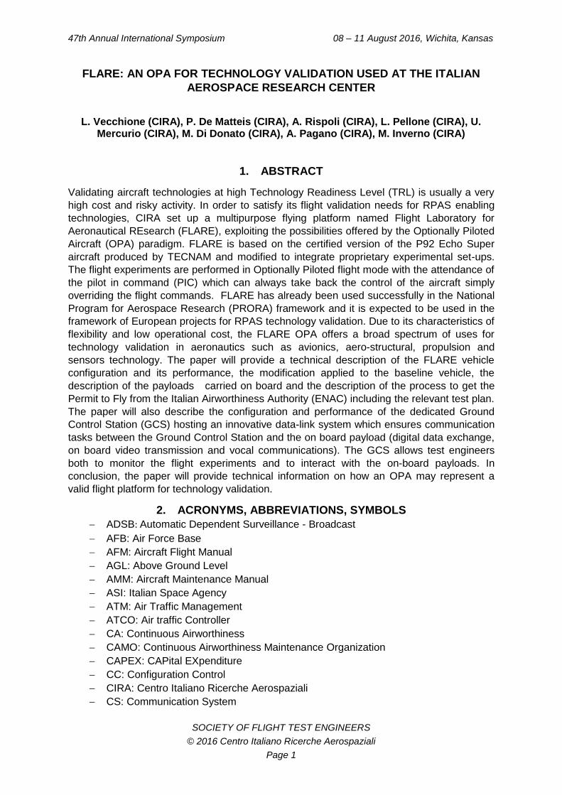
1. ABSTRACT
Validating aircraft technologies at high Technology Readiness Level (TRL) is usually a very
high cost and risky activity. In order to satisfy its flight validation needs for RPAS enabling
technologies, CIRA set up a multipurpose flying platform named Flight Laboratory for
Aeronautical REsearch (FLARE), exploiting the possibilities offered by the Optionally Piloted
Aircraft (OPA) paradigm. FLARE is based on the certified version of the P92 Echo Super
aircraft produced by TECNAM and modified to integrate proprietary experimental set-ups.
The flight experiments are performed in Optionally Piloted flight mode with the attendance of
the pilot in command (PIC) which can always take back the control of the aircraft simply
overriding the flight commands. FLARE has already been used successfully in the National
Program for Aerospace Research (PRORA) framework and it is expected to be used in the
framework of European projects for RPAS technology validation. Due to its characteristics of
flexibility and low operational cost, the FLARE OPA offers a broad spectrum of uses for
technology validation in aeronautics such as avionics, aero-structural, propulsion and
sensors technology. The paper will provide a technical description of the FLARE vehicle
configuration and its performance, the modification applied to the baseline vehicle, the
description of the payloads carried on board and the description of the process to get the
Permit to Fly from the Italian Airworthiness Authority (ENAC) including the relevant test plan.
The paper will also describe the configuration and performance of the dedicated Ground
Control Station (GCS) hosting an innovative data-link system which ensures communication
tasks between the Ground Control Station and the on board payload (digital data exchange,
on board video transmission and vocal communications). The GCS allows test engineers
both to monitor the flight experiments and to interact with the on-board payloads. In
conclusion, the paper will provide technical information on how an OPA may represent a
valid flight platform for technology validation.
2. ACRONYMS, ABBREVIATIONS, SYMBOLS
ADSB: Automatic Dependent Surveillance - Broadcast
AFB: Air Force Base
AFM: Aircraft Flight Manual
AGL: Above Ground Level
AMM: Aircraft Maintenance Manual
ASI: Italian Space Agency
ATM: Air Traffic Management
ATCO: Air traffic Controller
CA: Continuous Airworthiness
CAMO: Continuous Airworthiness Maintenance Organization
CAPEX: CAPital EXpenditure
CC: Configuration Control
CIRA: Centro Italiano Ricerche Aerospaziali
CS: Communication System
47th Annual International Symposium Wichita, Kansas
SOCIETY OF FLIGHT TEST ENGINEERS Page 2
DOC: Direct Operating Cost
EASA: European Aviation Safety Agency
ENAC: Ente Nazionale Aviazione Civile
EPCU: Electric Power Control Unit
EPMS: Electrical Power Management System
FD: Flight Director
FLARE: Flying Laboratory for Aerospace Research
FCC: Flight Control Computer
FTI: Flight test Instrumentation
FTP: Flight Test Plan
GCS: Ground Control Station
GNC: Guidance, Navigation and Control
GPS: Global Positioning System
MTOW: Maximum take-off weight
NOTAM: Notice-to Airmen
OPA: Optionally Piloted Aircraft
PIC: Pilot in Command
PRORA: PROgramma nazionale di Ricerca Aerospaziale
PTF: Permit to Fly
RFO: Remote Flight Operator
SOF: Safety of Flight
VLA: Very Light Aircraft
VMC: Visual Meteorological Conditions
VTS: Vehicle Tracking System
3. INTRODUCTION
While the term “low cost” is easily associated to commercial air transportation in the common
view of providing cheap flights to passengers, it may not be the case for flying experimental
payloads. Indeed, flight tests are still very “high cost”, lengthy and risky activity and may
easily turn into the worst nightmare for aerospace program managers. However, without
going into real flight conditions, no aerospace technology can get the label “flight qualified”
which opens the door to deploying technologies into real products. Being more and more
involved in R&TD projects requiring flight test demonstration, the Italian Aerospace
Research Center (CIRA) has developed a different approach in order to get rid of the cost
and the logistic burdens typically associated to flight experiments without losing significance
in the research outcome.
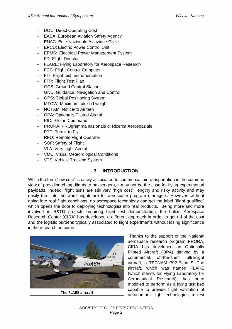
Thanks to the support of the National
aerospace research program PRORA,
CIRA has developed an Optionally
Piloted Aircraft (OPA) derived by a
commercial, off-the-shelf, ultra-light
aircraft, a TECNAM P92-Echo S. The
aircraft, which was named FLARE
(which stands for Flying Laboratory for
Aeronautical Research), has been
modified to perform as a flying test bed
capable to provide flight validation of
autonomous flight technologies, to test The FLARE aircraft
47th Annual International Symposium Wichita, Kansas
SOCIETY OF FLIGHT TEST ENGINEERS Page 3
traffic separation scenario based on ADS-B technology and improve weather-forecast
satellite based systems. CIRA also plans to use FLARE, in future, for the development of
aero-structural innovative technologies such morphing wing and propulsion, as part of the
Italian Aerospace Research program (PRORA).
In order to get the authorization to fly the modified aircraft under the current Italian
airworthiness regulation, CIRA has coordinated a complex technical effort which included
design, modifications as well as continuous airworthiness of the basic aircraft and its
systems, producing the necessary documentation to ensure the compliance to the CS-VLA
(Very Light aircraft) certification regulation, adopted as a reference. This technical process
involved the contributions of nearby airframe manufacturers such as TECNAM and
OMASUD, the local Flying Club and external consultants for the development of the
necessary documentation contributing to the Safety of Flight assessment issued under CIRA
responsibility.
Thanks to a fruitful technical cooperation with the Italian Civil Aviation Authority (ENAC),
CIRA has finally achieved the relevant Permit to Fly (PTF) on April 14, 2016. The permit,
valid for one year, has been issued on the basis of the system and safety documentation
produced by CIRA in accordance with the recent ENAC NAV32E regulation relevant in-flight
testing activities.
As soon as the PTF was available, CIRA started an intensive test campaign, which included
a maximum of 38 experimental flights, operating the aircraft from the local Capua airport
(ICAO LIAU).
4. THE OPA PARADIGM
A clear definition of OPA does not exist yet within European airworthiness rules. However,
since 2010, this category has been subject of the FAA order 8130.34 which defined the rules
for “Airworthiness Certification of Unmanned Aircraft Systems and Optionally Piloted
Aircraft”. This order establishes procedures for issuing special airworthiness certificates in
the experimental category or special flight permits to unmanned aircraft systems (UAS),
optionally piloted aircraft (OPA), and aircraft intended to be flown as either a UAS or an
OPA, under the designation OPA/UAS. According to FAA an OPA is “an aircraft flown with a
safety pilot onboard where remote control of the aircraft may be engaged or disengaged by
the safety pilot. Once the system controls are engaged, the aircraft is controlled by a pilot
operating the ground control station. Whether the system control is engaged or not, the pilot
in command (PIC) will always be the pilot sitting in the aircraft.” The paradigm is based on an
on-board safety pilot (i.e. PIC, pilot in command) for the purpose of overriding the system in
the case of malfunction or any other hazardous situation.
According to FAA order 8130.34, all traditional manned aircraft are in principle eligible for
modification. CIRA choose to modify a TECNAM P92 Echo Super for its low CAPEX, low
DOC, easiness of airworthiness support since the factory is nearby CIRA premises and for
the availability of an EASA certified version. Although this FAA order was not applicable in
Italy, it represented a sound reference for the purpose of obtaining a Permit-to-Fly and many
of the decisions taken along the process to get the Italian permit-to-fly were quite similar to
those suggested or requested by FAA.
The validity of the OPA paradigm is being demonstrated in several projects worldwide as it is
becoming more and more accepted for its cost and operation benefits. Recent European
projects include:
47th Annual International Symposium Wichita, Kansas
SOCIETY OF FLIGHT TEST ENGINEERS Page 4
EPCU
AT2TECH RV-OPV-EV a two-place, single-engine LSA aircraft based on the Evektor
Eurostar SLW
Diamond DA42 Centaur Optionally Piloted Aircraft (OPA) developed together with
AURORA SCIENCES
Q01 MALE optionally-piloted aircraft developed by Reiner Stemme Utility Air
Systems (RS-UAS), primarily for the Qatar Armed Forces.
5. OVERVIEW OF THE FLARE FLYING PLATFORM
FLARE is based on a P92 ECHO S, serial number
869, an ultra-light aircraft manufactured by
TECNAM Aeronautical Construction with a MTOW
of 450 kg and 100 Hp ROTAX engine 912 LS. The
Echo S has an EASA certified version, which is
the P92 JS, with higher MTOW (550 kg) and same
engine power. In order to support the Permit-to-
Fly process, TECNAM issued a compliance
declaration, stating the similarity of the P92 Echo
S to P92JS and identifying the minor structural
modifications necessary to ensure similarity such
as the installation of the stronger wing struts
foreseen in the JS certified version.
With respect to the P92 JS, CIRA implemented other aircraft modifications in order to
transform a conventional ultra-light aircraft in a flying laboratory. These modifications
included:
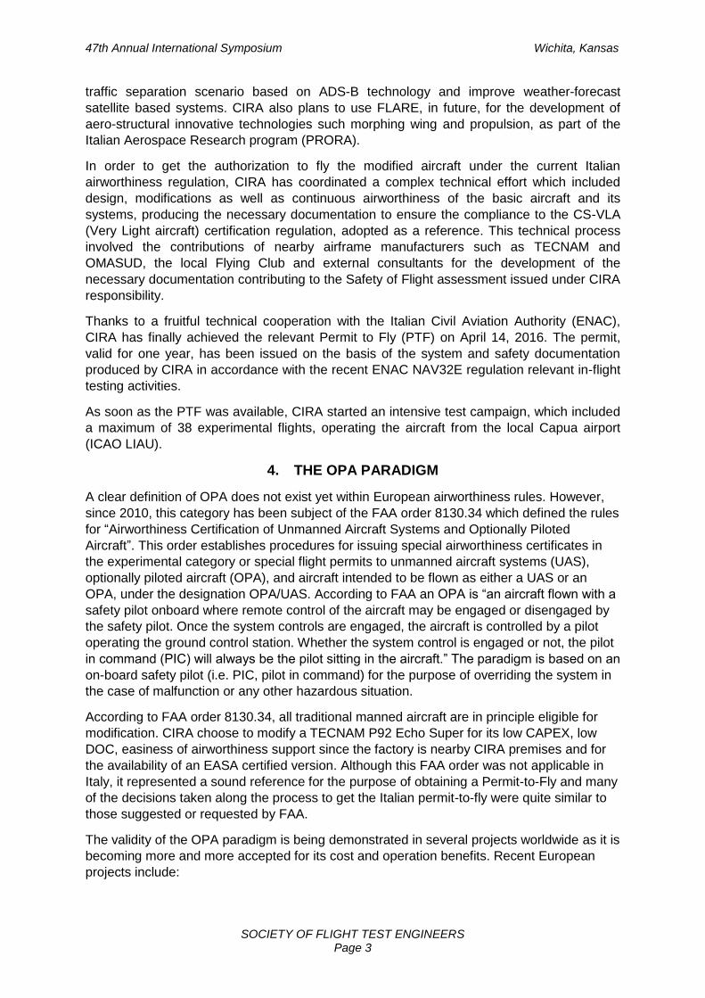
an auxiliary 3 kW alternator with a larger engine nacelle;
an air data boom near the left wing tip;
the removal of the left (pilot) seat in order to make room for the scientific payload;
the installation of equipment supporting plates in the baggage compartment;
inspection openings and small fixtures on the fuselage and wing panels to allow
installation of antennas and instrumentation.
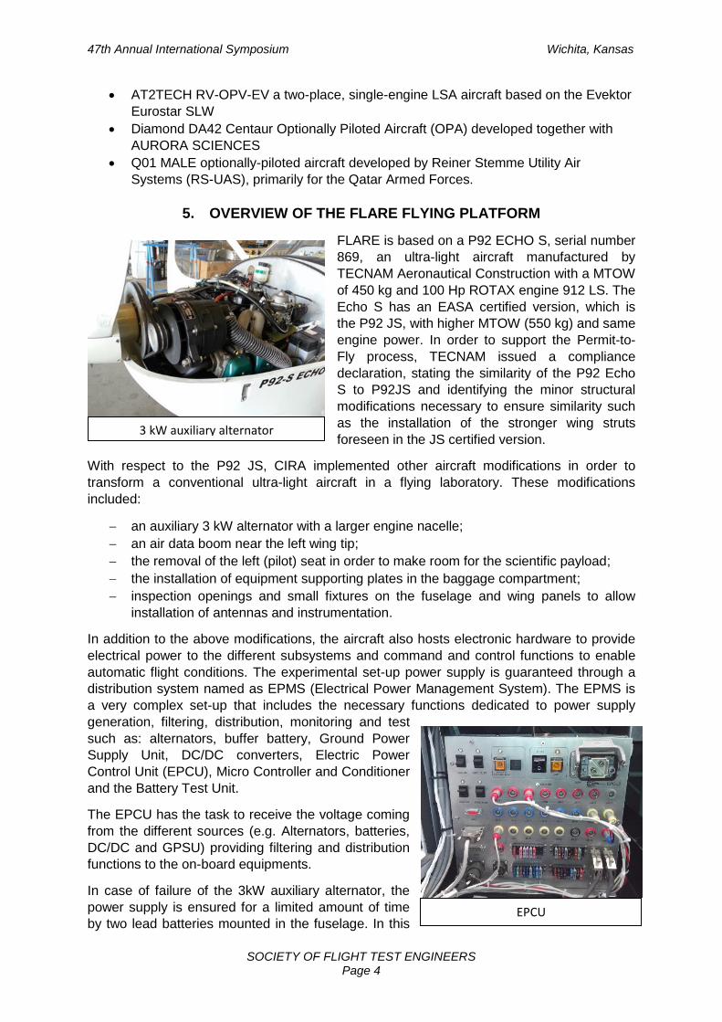
In addition to the above modifications, the aircraft also hosts electronic hardware to provide
electrical power to the different subsystems and command and control functions to enable
automatic flight conditions. The experimental set-up power supply is guaranteed through a
distribution system named as EPMS (Electrical Power Management System). The EPMS is
a very complex set-up that includes the necessary functions dedicated to power supply
generation, filtering, distribution, monitoring and test
such as: alternators, buffer battery, Ground Power
Supply Unit, DC/DC converters, Electric Power
Control Unit (EPCU), Micro Controller and Conditioner
and the Battery Test Unit.
The EPCU has the task to receive the voltage coming
from the different sources (e.g. Alternators, batteries,
DC/DC and GPSU) providing filtering and distribution
functions to the on-board equipments.
In case of failure of the 3kW auxiliary alternator, the
power supply is ensured for a limited amount of time
by two lead batteries mounted in the fuselage. In this
3 kW auxiliary alternator
47th Annual International Symposium Wichita, Kansas
SOCIETY OF FLIGHT TEST ENGINEERS Page 5
event, the system will feed some of the loads of the experimental set-up for about twenty
seconds. The system is also designed to ensure protection for all the loads supplied directly
through fuses placed upstream of the power cables. Two circuit breakers are installed. The
first protects the general line feed may be used by the on-board pilot to shut-off the whole
experimental set-up. The second breaker is located to protect the power line from the
alternator voltage regulator (ACU). Both are located at the bottom of the cockpit in a position
clearly visible to the pilot.
Guidance Navigation & Control
(GNC)Avionic Sensors
ADS-B
On Board Communication System
RFO Images & Encoding
Throttle & Primary Surfaces
Actuation
Dif
fere
nti
al C
orr
ecti
on
DATALINK (Video & Telemetry)
On Ground Communication System
ON BOARD SYSTEM
ON GROUND SYSTEM
Weather Measurements
RFO StationGPS Base Station
Diffe
ren
tia
l C
orr
ectio
n
Experiment Monitoring & Control Station
Flight Director Station
Tele
met
ry
Co
nfi
gura
tio
n
Flight Director
Remote Flight
Operator
On
Bo
ard
Vid
eo
Experiment Operators
On Board Pilot
Engine
Secondary Surfaces
Throttle & Primary Surfaces
Secondary Surfaces
Servo Actuation
Power Supply
VHF Radios
PS Status
AlternatorMechanical Link
Secondary Surfaces Command
Star
t Te
st
Alternator Status
Power off
Faci
lity
Stat
us
Clutch Activation
Power Supply
Pilot Interface
Mec
han
ical
Lin
k
Secon
dary Su
rfaces com
man
d
Deviator Position Command
Deviator
Clutches
Tele
met
ry
Mec
han
ical
Lin
k
Cooperative Traffic
Tele
met
ry
Tele
com
man
ds Video Recoder
Cockpit Screen
FD Screen
Cameras
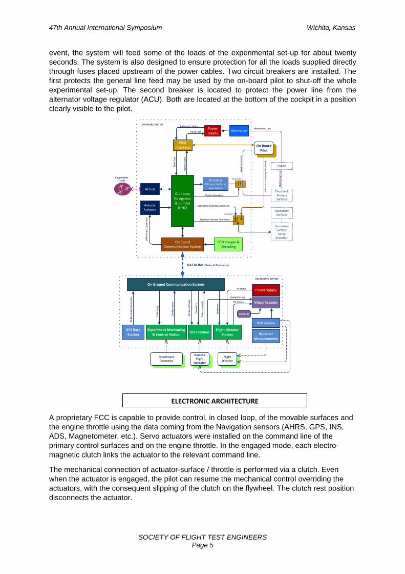
A proprietary FCC is capable to provide control, in closed loop, of the movable surfaces and
the engine throttle using the data coming from the Navigation sensors (AHRS, GPS, INS,
ADS, Magnetometer, etc.). Servo actuators were installed on the command line of the
primary control surfaces and on the engine throttle. In the engaged mode, each electro-
magnetic clutch links the actuator to the relevant command line.
The mechanical connection of actuator-surface / throttle is performed via a clutch. Even
when the actuator is engaged, the pilot can resume the mechanical control overriding the
actuators, with the consequent slipping of the clutch on the flywheel. The clutch rest position
disconnects the actuator.
ELECTRONIC ARCHITECTURE
47th Annual International Symposium Wichita, Kansas
SOCIETY OF FLIGHT TEST ENGINEERS Page 6
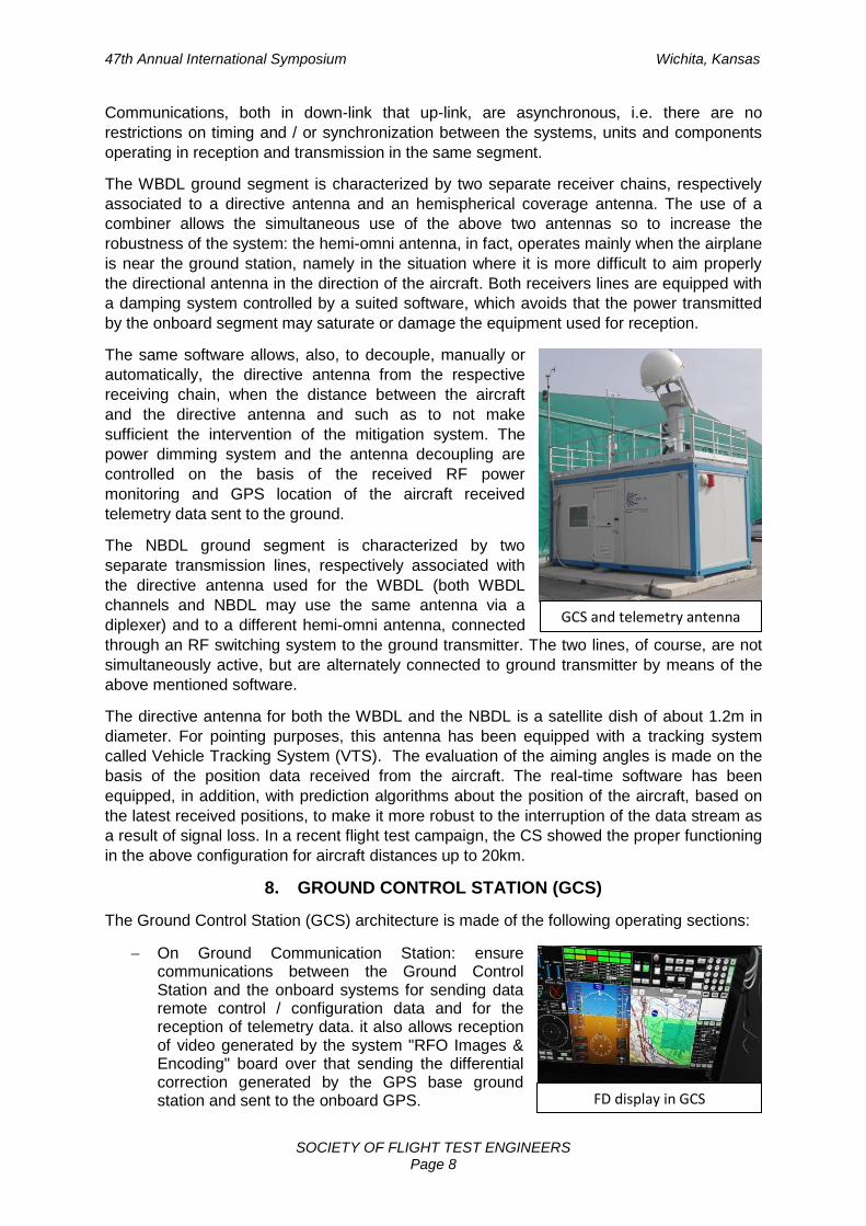
FLARE cockpit
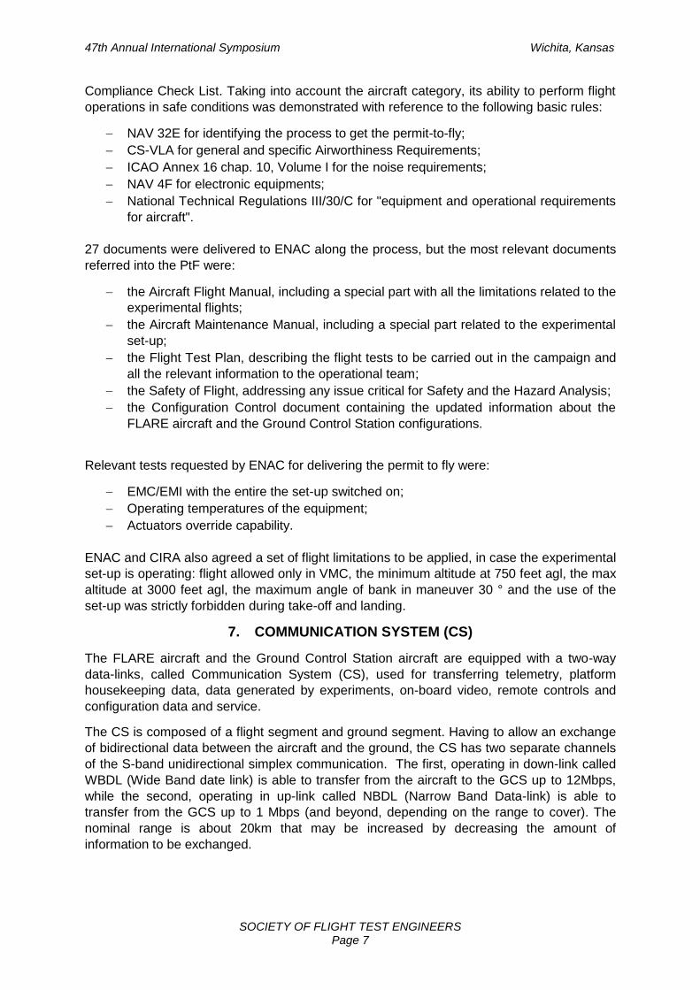
To accommodate all experimental avionics on
board, the left seat was removed and the baggage
bay space was used as well. By doing so, the major
portion of the equipments were installed inside the
cabin for easier operation and maintenance. For a
more rational installation of the embarked systems,
three mounting trays were designed to fit the
different equipment. Their design was part of the
structural verification process in order to ensure the
capability to withstand the expected load conditions.
The communication, positioning and datalink tasks were allowed by a number of different
antennas for the execution of the flight experiments, which were not part of the JS version. In
total, 2 VHF antenna, 3 GPS antennas, 2 LOS Data-link antennas, 1 ADSB receiver antenna
and 1 ADSB transponder-out antenna plus a satellite link antenna were installed on the
upper wing and on top/bottom fuselage.
Finally, the original cockpit was modified to
install additional visual alarms, instruments and
markings to be managed by the safety pilot
during the remote and automatic flight piloting
phases.
The experimental sections of the cockpit
containing FTI displays were delimited by the
typical orange strips.
6. THE AIRWORTHINESS FRAMEWORK
The fundamental paradigm, upon which the entire airworthiness process was based, is the
similarity between the P92 Echo S and the EASA certified version P92 JS acknowledged
by ENAC. Therefore, only the differences with respect to the JS version were subject to
ENAC verification in a supplemental logic. From the flight safety standpoint, the presence of
a pilot in command on board, typically a production test pilot acting as safety pilot capable to
take over the control of the aircraft at any time and under any operating condition of the
experimental set-up, was also an important pillar of the PtF process.
The compliance to each requirement was achieved by providing the necessary documental
evidence to ENAC, which approved its content thru a formal review process, by using a
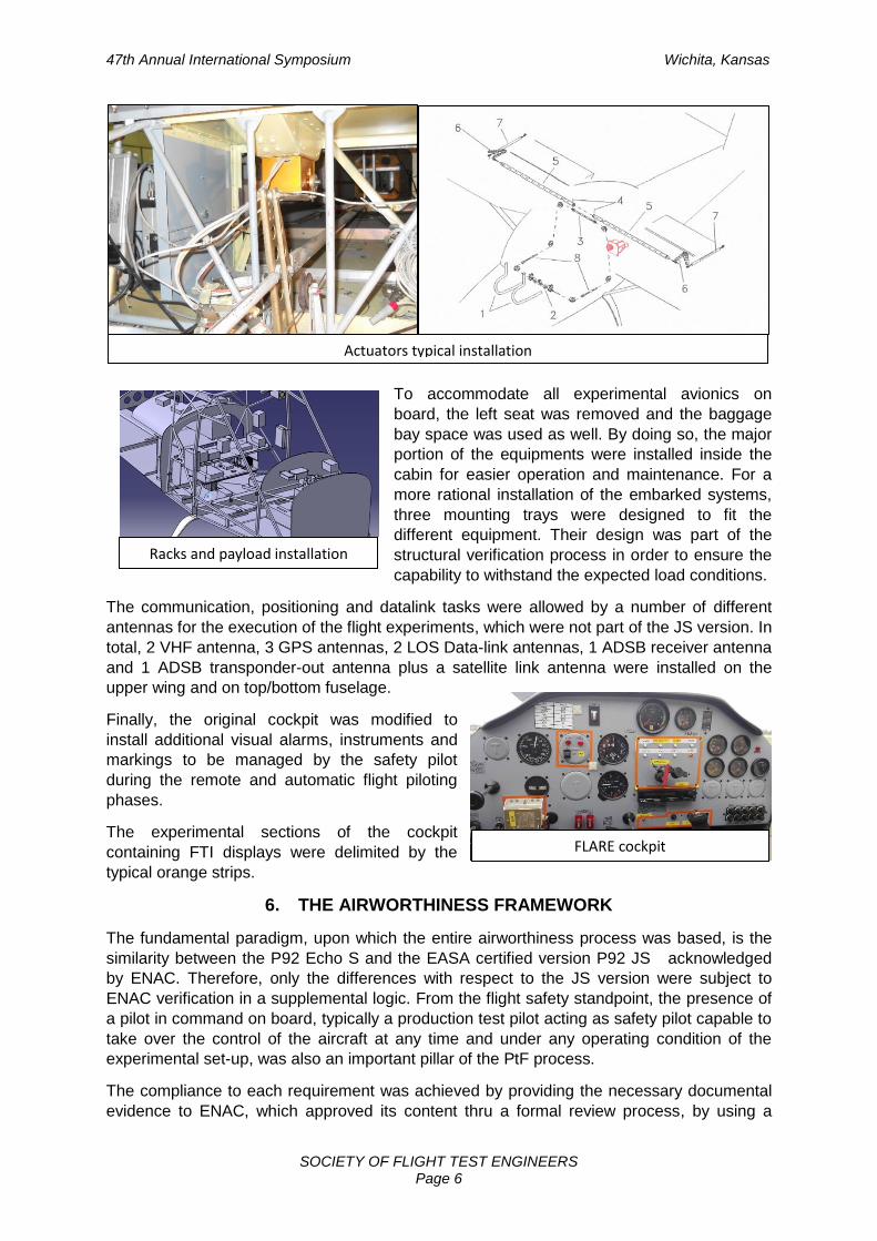
Actuators typical installation
Racks and payload installation
47th Annual International Symposium Wichita, Kansas
SOCIETY OF FLIGHT TEST ENGINEERS Page 7
Compliance Check List. Taking into account the aircraft category, its ability to perform flight
operations in safe conditions was demonstrated with reference to the following basic rules:
NAV 32E for identifying the process to get the permit-to-fly;
CS-VLA for general and specific Airworthiness Requirements;
ICAO Annex 16 chap. 10, Volume I for the noise requirements;
NAV 4F for electronic equipments;
National Technical Regulations III/30/C for "equipment and operational requirements
for aircraft".
27 documents were delivered to ENAC along the process, but the most relevant documents
referred into the PtF were:
the Aircraft Flight Manual, including a special part with all the limitations related to the
experimental flights;
the Aircraft Maintenance Manual, including a special part related to the experimental
set-up;
the Flight Test Plan, describing the flight tests to be carried out in the campaign and
all the relevant information to the operational team;
the Safety of Flight, addressing any issue critical for Safety and the Hazard Analysis;
the Configuration Control document containing the updated information about the
FLARE aircraft and the Ground Control Station configurations.
Relevant tests requested by ENAC for delivering the permit to fly were:
EMC/EMI with the entire the set-up switched on;
Operating temperatures of the equipment;
Actuators override capability.
ENAC and CIRA also agreed a set of flight limitations to be applied, in case the experimental
set-up is operating: flight allowed only in VMC, the minimum altitude at 750 feet agl, the max
altitude at 3000 feet agl, the maximum angle of bank in maneuver 30 ° and the use of the
set-up was strictly forbidden during take-off and landing.
7. COMMUNICATION SYSTEM (CS)
The FLARE aircraft and the Ground Control Station aircraft are equipped with a two-way
data-links, called Communication System (CS), used for transferring telemetry, platform
housekeeping data, data generated by experiments, on-board video, remote controls and
configuration data and service.
The CS is composed of a flight segment and ground segment. Having to allow an exchange
of bidirectional data between the aircraft and the ground, the CS has two separate channels
of the S-band unidirectional simplex communication. The first, operating in down-link called
WBDL (Wide Band date link) is able to transfer from the aircraft to the GCS up to 12Mbps,
while the second, operating in up-link called NBDL (Narrow Band Data-link) is able to
transfer from the GCS up to 1 Mbps (and beyond, depending on the range to cover). The
nominal range is about 20km that may be increased by decreasing the amount of
information to be exchanged.
47th Annual International Symposium Wichita, Kansas
SOCIETY OF FLIGHT TEST ENGINEERS Page 8
FD display in GCS
GCS and telemetry antenna
Communications, both in down-link that up-link, are asynchronous, i.e. there are no
restrictions on timing and / or synchronization between the systems, units and components
operating in reception and transmission in the same segment.
The WBDL ground segment is characterized by two separate receiver chains, respectively
associated to a directive antenna and an hemispherical coverage antenna. The use of a
combiner allows the simultaneous use of the above two antennas so to increase the
robustness of the system: the hemi-omni antenna, in fact, operates mainly when the airplane
is near the ground station, namely in the situation where it is more difficult to aim properly
the directional antenna in the direction of the aircraft. Both receivers lines are equipped with
a damping system controlled by a suited software, which avoids that the power transmitted
by the onboard segment may saturate or damage the equipment used for reception.
The same software allows, also, to decouple, manually or
automatically, the directive antenna from the respective
receiving chain, when the distance between the aircraft
and the directive antenna and such as to not make
sufficient the intervention of the mitigation system. The
power dimming system and the antenna decoupling are
controlled on the basis of the received RF power
monitoring and GPS location of the aircraft received
telemetry data sent to the ground.
The NBDL ground segment is characterized by two
separate transmission lines, respectively associated with
the directive antenna used for the WBDL (both WBDL
channels and NBDL may use the same antenna via a
diplexer) and to a different hemi-omni antenna, connected
through an RF switching system to the ground transmitter. The two lines, of course, are not
simultaneously active, but are alternately connected to ground transmitter by means of the
above mentioned software.
The directive antenna for both the WBDL and the NBDL is a satellite dish of about 1.2m in
diameter. For pointing purposes, this antenna has been equipped with a tracking system
called Vehicle Tracking System (VTS). The evaluation of the aiming angles is made on the
basis of the position data received from the aircraft. The real-time software has been
equipped, in addition, with prediction algorithms about the position of the aircraft, based on
the latest received positions, to make it more robust to the interruption of the data stream as
a result of signal loss. In a recent flight test campaign, the CS showed the proper functioning
in the above configuration for aircraft distances up to 20km.
8. GROUND CONTROL STATION (GCS)
The Ground Control Station (GCS) architecture is made of the following operating sections:
On Ground Communication Station: ensure communications between the Ground Control Station and the onboard systems for sending data remote control / configuration data and for the reception of telemetry data. it also allows reception of video generated by the system "RFO Images & Encoding" board over that sending the differential correction generated by the GPS base ground station and sent to the onboard GPS.
47th Annual International Symposium Wichita, Kansas
SOCIETY OF FLIGHT TEST ENGINEERS Page 9
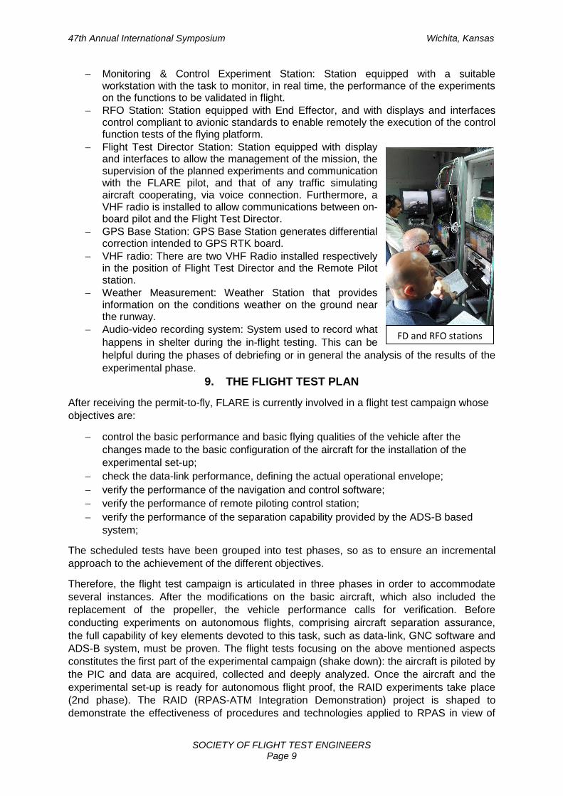
FD and RFO stations
Monitoring & Control Experiment Station: Station equipped with a suitable workstation with the task to monitor, in real time, the performance of the experiments on the functions to be validated in flight.
RFO Station: Station equipped with End Effector, and with displays and interfaces control compliant to avionic standards to enable remotely the execution of the control function tests of the flying platform.
Flight Test Director Station: Station equipped with display and interfaces to allow the management of the mission, the supervision of the planned experiments and communication with the FLARE pilot, and that of any traffic simulating aircraft cooperating, via voice connection. Furthermore, a VHF radio is installed to allow communications between on-board pilot and the Flight Test Director.
GPS Base Station: GPS Base Station generates differential correction intended to GPS RTK board.
VHF radio: There are two VHF Radio installed respectively in the position of Flight Test Director and the Remote Pilot station.
Weather Measurement: Weather Station that provides information on the conditions weather on the ground near the runway.
Audio-video recording system: System used to record what
happens in shelter during the in-flight testing. This can be
helpful during the phases of debriefing or in general the analysis of the results of the
experimental phase.
9. THE FLIGHT TEST PLAN
After receiving the permit-to-fly, FLARE is currently involved in a flight test campaign whose
objectives are:
control the basic performance and basic flying qualities of the vehicle after the
changes made to the basic configuration of the aircraft for the installation of the
experimental set-up;
check the data-link performance, defining the actual operational envelope;
verify the performance of the navigation and control software;
verify the performance of remote piloting control station;
verify the performance of the separation capability provided by the ADS-B based
system;
The scheduled tests have been grouped into test phases, so as to ensure an incremental
approach to the achievement of the different objectives.
Therefore, the flight test campaign is articulated in three phases in order to accommodate
several instances. After the modifications on the basic aircraft, which also included the
replacement of the propeller, the vehicle performance calls for verification. Before
conducting experiments on autonomous flights, comprising aircraft separation assurance,
the full capability of key elements devoted to this task, such as data-link, GNC software and
ADS-B system, must be proven. The flight tests focusing on the above mentioned aspects
constitutes the first part of the experimental campaign (shake down): the aircraft is piloted by
the PIC and data are acquired, collected and deeply analyzed. Once the aircraft and the
experimental set-up is ready for autonomous flight proof, the RAID experiments take place
(2nd phase). The RAID (RPAS-ATM Integration Demonstration) project is shaped to
demonstrate the effectiveness of procedures and technologies applied to RPAS in view of
47th Annual International Symposium Wichita, Kansas
SOCIETY OF FLIGHT TEST ENGINEERS Page 10
their integration in the civil aviation system. Such an integration stems from the perspective
of the future ATM (Air Traffic Management) system proposed and developed by SESAR (the
Single European Sky ATM Research initiative). For this purpose, the cooperating traffic is
represented by two aircrafts, one of them is a manned aircraft of the same class of FLARE
and the other is a small RPAS whose weight does not exceed 5Kg. The procedures define
the kind of interactions among the involved test operators, mainly the remote flight operator
(RFO) and the simulated air traffic control officer (ATCO2) which intervenes for all of the
operation within the flight test area while the real air traffic control officer (ATCO1) manages
interactions between the aircraft concerned in the tests and the general aviation traffic. The
technologies that constitutes the core of the experimental set-up are based on sensors, on
actuation devices and on a flight control computer (FCC) which is equipped with proven
software to allow autonomous way-points navigation and separation assurance. As far as
autonomous navigation is concerned, the outcome of the RAID tests allows for a useful
evaluation of the operators performance (RFO and ATCO2), with particular reference to the
workload and situational awareness. With respect to the separation assurance, the
automatic management system of separation based on ADS-B aboard a RPAS is opposed
to the separation provided by ATCO. Flight demonstration intends to show that the proposed
algorithms are able to assure aircraft separation in real-time, so as to avoid situations of
potential conflict, even without the assistance of a human operator. As such, it can be
considered as a fundamental step for promoting the integration of unmanned aircraft into
non-segregated airspaces. Two of the flight tests of the RAID campaign are planned aiming
to verify the workload of RFO and ATCO2 in managing situations of loss of separation, due
to simulated conditions respectively of GPS spoofing and jamming (GPS signals are faked to
alter the aircraft real location and steer the aircraft to an unwanted location).
Finally, the 3rd phase of the flight test campaign concentrates on the AIRONE project
(sAtellite lInk for personal aiRcraft weather informatioN sErvice) which is a research initiative
jointly funded by ASI (Italian Space Agency) under the 3rd EMS Frame Program on TLC and
Integrated Applications. In this project, an avionic payload, consisting of a set of digital
sensors and devices for processing and storing data, is embarked on board for the
verification of systems to support navigation even in bad weather conditions.Basically, the
AIRONE system is a navigational aid in adverse weather conditions, capable of detecting
any hazard weather along the planned route and suggesting the pilot an alternative route by
which circumvent the hazard. The planned route, as well as the suggested alternate route,
are displayed by means of a tablet device portraying meteorological graphics and
geographic elements on the actual digital aeronautical map.
Taking into account all of the requirements coming from the three different phases of the test
campaign, the flight test area was identified bearing in mind the following considerations:
to avoid towns and densely populated areas;
to give priority to areas nearby CIRA premises and Capua airport to facilitate logistics
and ground operations;
to remain within Data-Link coverage limits;
to make sure the flight trajectory fall within the test area;
to minimize interferences with the airports of Capua and Grazzanise (and their air
spaces).
The flight test plan, which is one of the required document for achieving the PtF, has
resulted in a very detailed report where procedures are formalized, flight test scopes are
described, flight test cards are duly prepared and roles of each flight test team member are
clearly defined. Since the flight test area falls within the CTR of the Grazzanise Air Force
47th Annual International Symposium Wichita, Kansas
SOCIETY OF FLIGHT TEST ENGINEERS Page 11
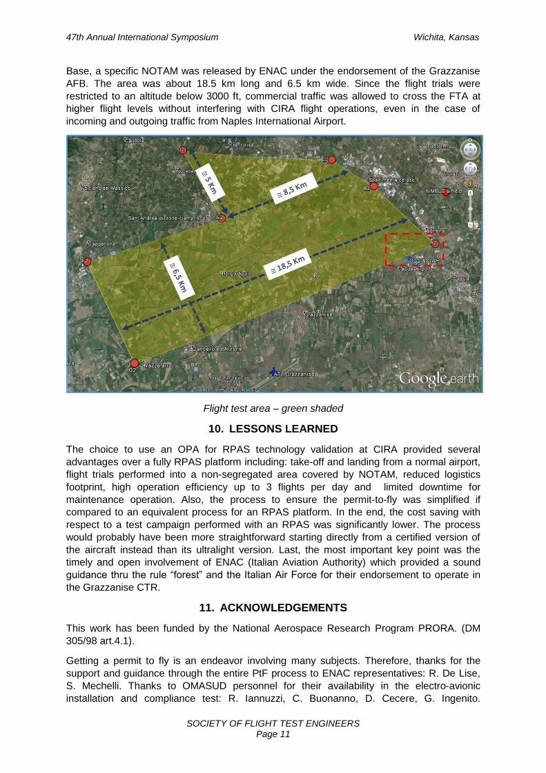
Base, a specific NOTAM was released by ENAC under the endorsement of the Grazzanise
AFB. The area was about 18.5 km long and 6.5 km wide. Since the flight trials were
restricted to an altitude below 3000 ft, commercial traffic was allowed to cross the FTA at
higher flight levels without interfering with CIRA flight operations, even in the case of
incoming and outgoing traffic from Naples International Airport.
Flight test area – green shaded
10. LESSONS LEARNED
The choice to use an OPA for RPAS technology validation at CIRA provided several
advantages over a fully RPAS platform including: take-off and landing from a normal airport,
flight trials performed into a non-segregated area covered by NOTAM, reduced logistics
footprint, high operation efficiency up to 3 flights per day and limited downtime for
maintenance operation. Also, the process to ensure the permit-to-fly was simplified if
compared to an equivalent process for an RPAS platform. In the end, the cost saving with
respect to a test campaign performed with an RPAS was significantly lower. The process
would probably have been more straightforward starting directly from a certified version of
the aircraft instead than its ultralight version. Last, the most important key point was the
timely and open involvement of ENAC (Italian Aviation Authority) which provided a sound
guidance thru the rule “forest” and the Italian Air Force for their endorsement to operate in
the Grazzanise CTR.
11. ACKNOWLEDGEMENTS
This work has been funded by the National Aerospace Research Program PRORA. (DM
305/98 art.4.1).
Getting a permit to fly is an endeavor involving many subjects. Therefore, thanks for the
support and guidance through the entire PtF process to ENAC representatives: R. De Lise,
S. Mechelli. Thanks to OMASUD personnel for their availability in the electro-avionic
installation and compliance test: R. Iannuzzi, C. Buonanno, D. Cecere, G. Ingenito.
47th Annual International Symposium Wichita, Kansas
SOCIETY OF FLIGHT TEST ENGINEERS Page 12
TECNAM has been very supportive in providing timely technical advice and releasing to
service the aircraft: M. Oliva, N. De Donato, B. Silvestro, D. Rullo. Thanks also to Gen. C.
Landi who provided support to the elaboration of the “Safety of Flight” document and acting
as Flight Director and Safety Officer during the first flights. Finally, the Capua Flying Club
that provided efficient logistics and operation support in the person of Commander F.
Taglialatela. Many CIRA departments have contributed to the achievement described in this
paper: AERO, AFSI, ELTD, SBAT and SOTA. Kudos to everybody !
12. REFERENCE 1. Harvey M. Gates, John C. Knudsen, “A Case for Optionally Piloted Vehicle Research
and Development”, Rohnert Park, CA, 2007, AIAA Paper 2007-2760. 2. J. Utt, J. McCalmont, M. Deschenes, Test and Integration of a Detect and Avoid
System”, Chicago, IL, 2004, AIAA Paper 2004-6329. 3. P. S. Anderson, “Development of a UAV Ground Control Station”, MSc. Thesis,
Linkoping University, 2002. 4. J. Walker, R. Kenagy, “Guidance Material and Consideration for Unmanned Aircraft
Systems”, 5. “Development and Operation of UAVs for Military and Civil Applications”, RTO-EN-9,
2000. 6. S. Palazzo, L. Vecchione, A. Rispoli, F. Valenza, “Configuration of an Optionally
Piloted Vehicle as Flying Laboratory for Aeronautical Research”, RTO-SCI-202 Symposium “Intelligent Uninhabited Vehicle Guidance Systems” Neubiberg, July 2009.
7. E. Filippone, V. Di Vito, G. Torrano, “RPAS – ATM Integration Demonstration – Real-Time Simulation Results”, 15th AIAA Aviation Technology, Integration, and Operations Conference
8. M. Orefice, V. Di Vito, F. Corraro, D. Accardo, “Aircraft conflict detection based on ADS-B surveillance data”, Conference: 2014 IEEE Metrology for Aerospace (MetroAeroSpace).
9. Merlin, P.W. (2013), “Crash Course: lessons learned from accidents involving remotely piloted and autonomous aircraft”, NASA SP 2013-600.
10. Thompson, W.T., Tvaryanas, A.P & Constable, S.H. (2005), “U.S. Military Unmanned Aerial Vehicle Mishaps: Assessment of the Role of Human Factors Using Human Factors Analysis and Classification System (HFACS)”, HSW-PE-BR-TR-2005-0001.
11. Tvaryanas, A.P. & Thompson, W.T. (2006), Unmanned Aircraft System (UAS) Operator Error Mishaps: An Evidence-based Prioritization of Human Factors Issues, RTO-MP-HFM-135.
12. Williams, K.W. (2004), “A Summary of Unmanned Aircraft Accident/Incident Data: Human Factors Implications”, DOT/FAA/AM-04/24.
13. Ryan T. Olson, Chris M. McElroy, Remotely Piloted Vehicle Flight Test Technique Development and Training at NTPS, STO-MP-SCI-269, 2014
14. Unique Aspects of Flight Testing Unmanned Aircraft Systems AG-300-V22. North Atlantic Treaty Organization, 2010.
15. Cotting, C., UAV Performance Rating Scale Based on the Cooper-Harper Piloted Rating Scale, Virginia, Polytechnic Institute and State University, 2011.
16. Cummings, M.L., Myers, K., Scott, Modified Cooper Harper Evaluation Tool for Unmanned Vehicle Display,. S.D., Massachusetts Institute of Technology, 2006.
17. Roadmap for the integration of civil RPAS into the European Aviation System. 2012. ERStG Final Report
18. Initial Concept of Operation for UAS in SESAR. 2012, ICONUS 19. General Considerations for Civilian Operation of Unmanned Aircraft,2012, EUROCAE. 20. “NAV32E - Permessi Di Volo ed Attivita' Sperimentale”, ENAC, 2015 21. FAA order 8130.34 “Airworthiness Certification of Unmanned Aircraft Systems and
Optionally Piloted Aircraft”.