fixed wing uav
DESCRIPTION
Our FYP Includes a mechanism to transmit a live video over the Internet from the UAV, using Raspberry PiTRANSCRIPT
FIXED WING UAV
Undergraduate graduation project Report
Submitted in partial fulfillment of
the requirements for the
Degree of Bachelor of Science of Engineering
in
Department of Electronic & Telecommunication Engineering
University of Moratuwa
Supervisor: Group Members:
Prof. S.R. Munasinghe Gamage C. I.
Hemachandra P.M.
Lansakara L.M.S.C.
Wijesinghe D.M.P.
26 June 2014
i
Approval
Approval of the Department of Electronic & Telecommunication Engineering
……………………………………….
Head,
Department of Electronic &
Telecommunication Engineering
This is to certify that we have read this project and that in our opinion it is fully
adequate, in cope and quality, as an Undergraduate Graduation Project.
Supervisor Name: …………………………………….
Signature: ……………………………………...
Date: ……………………………………...
ii
Abstract
FIXED WING UNMANNED AERIAL VEHICLE
Supervisor: Prof. S.R. Munasinghe
Keywords: Fixed wing, UAV, twin boom, telemetry over IP, live video stream
.
Unmanned Aerial Vehicles industry as in a very developed stage in international
scale. They are used in military and civil applications worldwide. However using
UAVs in local applications is highly restricted due to the unavailability of technology
and high cost. Design methodologies for autopilot based UAVs are not publicly
shared due to trade and millitary secrets.
We have developed our own small scale UAVs based on Twin Boom and Blu Baby
UAV models.We implemented the autopilot system based on an open hardware
platform. Ravan can carry 8kg of weight with an endurance exceeding 30 minutes.
We have developed our own GCS (Ground Control Station) based on telemetry over
IP which provides real time information about the current status of the UAV and a
live video feed over the standard WCDMA network.
This project can be used as a foundation for further projects concentrating on
advanced aspects on autopilot system, live video transmission and dunamic path
selection.
iii
To our parents and teachers
iv

Acknowledgement
It’s with great pleasure that we express our heartfelt gratitude to all those who
supported and guided us to make this project a success. First we would like to convey
our gratitude to Prof. S.R. Munasinghe, our project supervisor for his immense
support and encouragement provided during the project duration. We would like to
extend our sincere thanks all the staff members for their valuable feedback during
feasibility study and mid review.
Our special thanks goes to our fellow senior students of the department Mr.
Anurudhdha Tennakoon and Mr. Tharindu Eranga Fernando for their valuable time
and advice on overcoming various hurdles we faced during the design process and
flight tests. Without their support a successful outcome would not have been possible.
Also our sincere thanks goes to Mr. Pasindu Rathnayake and Mr. Lakshman for
providing their expertise during the flight tests.
v
ContentsApproval................................................................................................................................... ii
Abstract.................................................................................................................................... iii
Acknowledgement....................................................................................................................v
List of Tables.............................................................................................................................x
List of Figures...........................................................................................................................xi
Figure 1.3.1.1 A twin boom UAV..............................................................................................xi
Figure 1.3.1.2 Autopilot System...............................................................................................xi
Figure 1.3.2.1 Block diagram of an autopilot system...............................................................xi
Figure 2.2.1 Cutting wood according to the dimensions..........................................................xi
Figure 2.2.2 Affixing parts using wood affixing glue.................................................................xi
Figure 2.2.3 Drilling in order to insert Aluminum tubes. Later these Aluminum rods were replaced with carbon fiber tubes.............................................................................................xi
Figure 2.2.4 Using covering films to cover the parts................................................................xi
Figure 2.2.5 Finished body.......................................................................................................xi
Figure 2.2.6 Developing a mold for the nose...........................................................................xi
Figure 2.2.7 Cutting the Styrofoam using a hot wire................................................................xi
Figure 2.2.8 Finished Wings.....................................................................................................xi
Figure 2.2.8 Final Design of Wings...........................................................................................xi
Figure 2.2.9 Different stages in building the empennage.........................................................xi
Figure2.2.10 Final Design of Landing Gears.............................................................................xi
Figure 2.2.10 RAVAN final design.............................................................................................xi
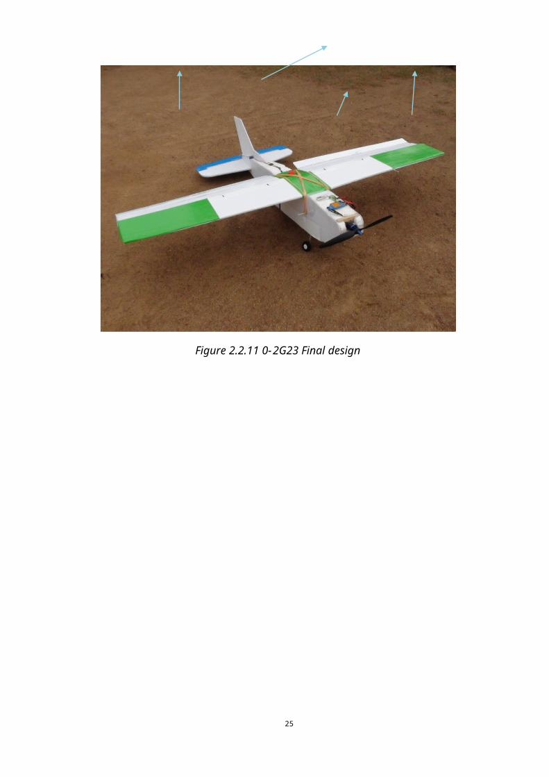
Figure 2.2.11 0 1G23 Final design............................................................................................xi
Figure 3.3.1.1. Crash analysis...................................................................................................xi
Figure 3.3.1.6 Structural Analysis Using XFLR5.........................................................................xi
Figure 3.3.1.8 Graph Analysis...................................................................................................xi
Figure 3.3.3.1 Fulltime Throttle Profile....................................................................................xi
Figure 3.3.3.2. Full time input profile.......................................................................................xi
Figure 3.3.3.3. full time output profile.....................................................................................xi
Figure 3.3.3.4 Full flight roll profile..........................................................................................xi
Figure 3.3.3.5 Flight Analysis....................................................................................................xi
Figure 3.3.4.1. Visual analysis G23 Fourth Flight'.....................................................................xi
Figure 3.3.5.1 High resolution Gopro camera view..................................................................xi
vi
Figure 4.1.1. Autopilot introduction.........................................................................................xi
Figure 4.2.1 Actuators in a UAV...............................................................................................xi
Figure 4.5.1 Fabriacated autopilot board.................................................................................xi
Figure 4.5.2 Schematic of Autopilot system.............................................................................xi
Figure 4.5.3 Final schematic of Autopilot Board......................................................................xi
Figure 4.5.6 bottom layer of Autopilot board..........................................................................xi
Figure 4.6.1.1. IMU..................................................................................................................xii
Figure4.6.2.1 airspeed sensor.................................................................................................xii
Figure 0 14.6.3.1. Barometer..................................................................................................xii
Figure 4.7.1 Issues in Autopilot board.....................................................................................xii
Figure 5.2.1 Raspberry Pi board..............................................................................................xii
Figure 5.2.2 Pandaboard.........................................................................................................xii
Figure 5.7.1 Raspberry Camera...............................................................................................xii
Figure 5.8.1.1 image of open network stream dialog with relevant settings..........................xii
1 Introduction...........................................................................................................................1
1.1 Nature and Scope of the Project.....................................................................................1
1.2 Review of Pertinent Literature........................................................................................4
1.3 Method of Implementation............................................................................................6
1.3.1 Structure and Avionics of the UAV...........................................................................6
1.3.2 Ground Control Station...........................................................................................9
1.4 Principal Results and Contributions..............................................................................10
2. Developing UAV Structure..................................................................................................11
2.1 Introduction..................................................................................................................11
2.2 Design procedure of RAVAN structure..........................................................................12
3. Avionics and Flight Analysis................................................................................................20
3.1 RAVAN UAV...................................................................................................................20
3.2 G23 aircraft...................................................................................................................22
3.2.1 UAV Configuration.................................................................................................22
3.2.2. Electronic configuration........................................................................................22
3.2.3Autopilot configuration...........................................................................................23
3.2.4 Telemetry configuration........................................................................................23
3.3 Flight test and summarized results...............................................................................24
4. Autopilot System................................................................................................................42
4.1 Introduction to autopilot systems.................................................................................42
vii
4.2 Main actuators in UAV..................................................................................................43
4.3 Initialization system......................................................................................................44
4.4 Flight Modes.................................................................................................................50
4.4.1 Manual Mode........................................................................................................50
4.4.2. Fly By Wire A.........................................................................................................50
4.4.3 Fly By Wire B..........................................................................................................51
4.4.4 Auto mode.............................................................................................................51
4.5 Autopilot board schematic and layout..........................................................................52
4.6 Sensors used in Autopilot System................................................................................55
4.6.1 IMU (inertial Measurement Unit)..........................................................................55
4.6.2 Airspeed sensor.....................................................................................................56
4.6.3 Barometer..............................................................................................................56
4.7 Autopilot board issues and overcomes.........................................................................58
5. Live Video and Telemetry...................................................................................................60
5.1 Introduction to problem addressed..............................................................................60
5.2 Methodology................................................................................................................61
5.3 Selecting a Single-board computer...............................................................................63
5.4 Raspberry Pi single board computer.............................................................................65
5.4.1 Configuring a webcam to work with Raspberry Pi.................................................65
5.4.2 Uploading video to Internet...................................................................................67
5.4.3 Results of this test..................................................................................................68
5.5 Power supply................................................................................................................69
5.6 VPN implementation.....................................................................................................69
5.7 Raspberry Camera.........................................................................................................69
5.7.1Testing the camera.................................................................................................70
5.8 Implementing video link using the point to point network...........................................70
5.8.1. Pi as server and GCS as client................................................................................70
5.8.2. GCS as server and Pi as client................................................................................72
5.8.3 Comparison between the two methods mentioned above...................................74
5.9 Selecting the most suitable video codec.......................................................................75
5.10 Conclusion..................................................................................................................77
5.11 Implementing telemetry over the point to point network..........................................78
6. Discussion and Conclusion..............................................................................................84
7. References..........................................................................................................................85
viii
ix
List of Tables
Table 1.1 Comparison of Military and Nonmilitary applications of UAVs
Table 2.1.1 Comparison of Ravan and G23
Table 3.1.1.1 Configuration of RAVAN
Table 3.1.1.2 Electronic Configuration of RAVAN
Table 3.2.1.1 G23 UAV configuration
Table 3.2.2.1 G23 electronic configuration
Table 4.3.1 Initializing stage activities
Table 4.3.2 Different stages in autopilot system
Table 5.4.2.1 Switches used in avconv
Table 5.8.1.1 Switches used in raspivid command
Table 5.8.2.1 Switches used in Netcat
Table 5.8.2.2 Switches used in raspivid
Table 5.9.1 Video delay with different settings
Table 5.9.2. Video results after modifications
x
List of FiguresFigure 1.3.1.1 A twin boom UAV
Figure 1.3.1.2 Autopilot System
Figure 1.3.2.1 Block diagram of an autopilot system
Figure 2.2.1 Cutting wood according to the dimensions
Figure 2.2.2 Affixing parts using wood affixing glue
Figure 2.2.3 Drilling in order to insert Aluminum tubes. Later these Aluminum
rods were replaced with carbon fiber tubes
Figure 2.2.4 Using covering films to cover the parts
Figure 2.2.5 Finished body
Figure 2.2.6 Developing a mold for the nose
Figure 2.2.7 Cutting the Styrofoam using a hot wire
Figure 2.2.8 Finished Wings
Figure 2.2.8 Final Design of Wings
Figure 2.2.9 Different stages in building the empennage
Figure2.2.10 Final Design of Landing Gears
Figure 2.2.10 RAVAN final design
Figure 2.2.11 0 1G23 Final design
Figure 3.3.1.1. Crash analysis
Figure 3.3.1.6 Structural Analysis Using XFLR5
Figure 3.3.1.8 Graph Analysis
Figure 3.3.3.1 Fulltime Throttle Profile
Figure 3.3.3.2. Full time input profile
Figure 3.3.3.3. full time output profile
Figure 3.3.3.4 Full flight roll profile
Figure 3.3.3.5 Flight Analysis
Figure 3.3.4.1. Visual analysis G23 Fourth Flight'
Figure 3.3.5.1 High resolution Gopro camera view
Figure 4.1.1. Autopilot introduction
Figure 4.2.1 Actuators in a UAV
Figure 4.5.1 Fabriacated autopilot board
Figure 4.5.2 Schematic of Autopilot system
xi

Figure 4.5.3 Final schematic of Autopilot Board
Figure 4.5.6 bottom layer of Autopilot board
Figure 4.6.1.1. IMU
Figure4.6.2.1 airspeed sensor
Figure 0 14.6.3.1. Barometer
Figure 4.7.1 Issues in Autopilot board
Figure 5.2.1 Raspberry Pi board
Figure 5.2.2 Pandaboard
Figure 5.7.1 Raspberry Camera
Figure 5.8.1.1 image of open network stream dialog with relevant settings
xii
1 Introduction
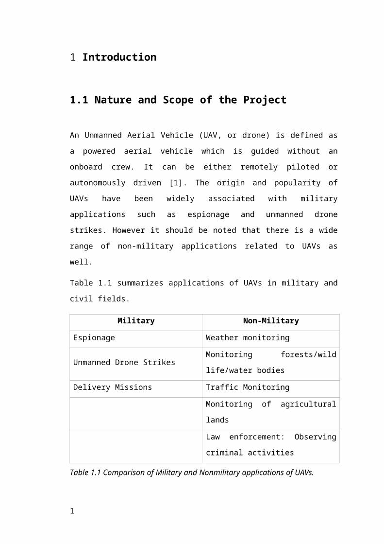
1.1 Nature and Scope of the Project
An Unmanned Aerial Vehicle (UAV, or drone) is defined as a powered aerial vehicle
which is guided without an onboard crew. It can be either remotely piloted or
autonomously driven [1]. The origin and popularity of UAVs have been widely
associated with military applications such as espionage and unmanned drone strikes.
However it should be noted that there is a wide range of non-military applications
related to UAVs as well.
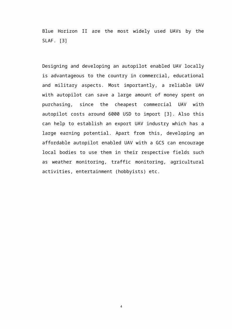
Table 1.1 summarizes applications of UAVs in military and civil fields.
Military Non-Military
Espionage Weather monitoring
Unmanned Drone Strikes Monitoring forests/wild life/water bodies
Delivery Missions Traffic Monitoring
Monitoring of agricultural lands
Law enforcement: Observing criminal
activities
Table 1.1 Comparison of Military and Nonmilitary applications of UAVs.
Ability to be used in extremely risky (military) activities without sacrificing lives is
the main advantage of using UAVs over manned aircraft. UAVs can be used in
recurring tasks such as monitoring an area by following a predetermined path in fully
automatic mode. This saves a considerable amount of pilot-hours and contributes to
cost reductions. Another advantage of UAVs is that it needs only a small crew to
monitor and control a large number of simultaneous flight missions carried out by a
several number of UAVs. Advanced ground stations such as QGroundControl [5]
supports up to 255 UAVs on one interface.
1
An autopilot is a mechanism which is capable of guiding a vehicle without human
assistance. [2] When applied in a UAV, an autopilot is capable of navigating to
hardcoded or dynamically provided waypoints. It should also be able to follow an
emergency landing or return home operation in unfavorable flight circumstances. The
autopilot should be alert of the power source and communicate with the ground
station appropriately sending all status messages as required in the mission.
Responding to commands from the ground station and altering the flight plan
accordingly is another expected function of a commercially competent autopilot
system.
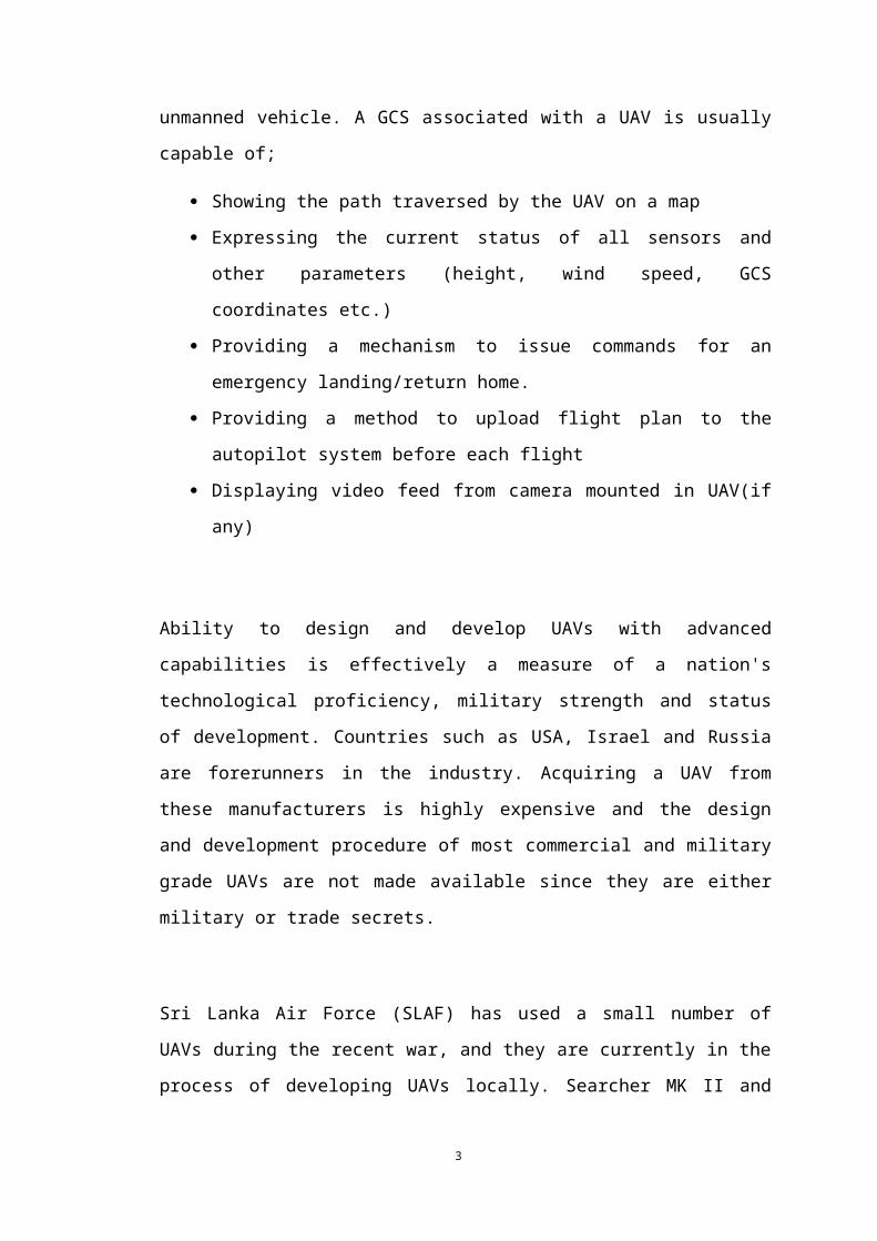
A Ground Control Station (GCS) is an interface which provides human operators a
means of interacting with an unmanned vehicle. A GCS associated with a UAV is
usually capable of;
Showing the path traversed by the UAV on a map
Expressing the current status of all sensors and other parameters (height, wind
speed, GCS coordinates etc.)
Providing a mechanism to issue commands for an emergency landing/return
home.
Providing a method to upload flight plan to the autopilot system before each
flight
Displaying video feed from camera mounted in UAV(if any)
Ability to design and develop UAVs with advanced capabilities is effectively a
measure of a nation's technological proficiency, military strength and status of
development. Countries such as USA, Israel and Russia are forerunners in the
industry. Acquiring a UAV from these manufacturers is highly expensive and the
design and development procedure of most commercial and military grade UAVs are
not made available since they are either military or trade secrets.
Sri Lanka Air Force (SLAF) has used a small number of UAVs during the recent war,
and they are currently in the process of developing UAVs locally. Searcher MK II and
Blue Horizon II are the most widely used UAVs by the SLAF. [3]
2
Designing and developing an autopilot enabled UAV locally is advantageous to the
country in commercial, educational and military aspects. Most importantly, a reliable
UAV with autopilot can save a large amount of money spent on purchasing, since the
cheapest commercial UAV with autopilot costs around 6000 USD to import [3]. Also
this can help to establish an export UAV industry which has a large earning potential.
Apart from this, developing an affordable autopilot enabled UAV with a GCS can
encourage local bodies to use them in their respective fields such as weather
monitoring, traffic monitoring, agricultural activities, entertainment (hobbyists) etc.
3
1.2 Review of Pertinent Literature
A UAV with an autopilot was designed and implemented by final year project group
22 of Department of Electronic and Telecommunication Engineering, University of
Moratuwa. This was supervised by Prof. Rohan Munasinghe and the final outcome
was a 'Blue Baby' UAV aircraft with a open source autopilot and a ground control
station [3]. The UAV in this project was able to traverse a given path with satisfactory
accuracy under autopilot mode. It was launched and landed manually. However since
this was a light aircraft, wind has influenced a lot in reaching the desired waypoints.
They have suggested a number of enhancements for follow up projects.
Structural modifications were recommended so that the UAV can carry a heavier
payload and be more unsusceptible under wind. This UAV has mounted the propeller
in the front for ease of design. However this damages the propeller in crash landings.
This is a main reason for the low payload capability of the aircraft. They have
suggested to use "Twin Boom" aircraft structure (Figure 1.2) in follow up projects.
Lack of endurance has been identified as a major drawback in this project. Endurance
is a major requirement for commercial success of a UAV since the UAV is required to
carry out long range missions. The small size of the UAV which results instability
and inability to carry a heavy battery is identified as the reasons for low endurance of.
A 2200 mAh, 3 cell battery was used in this project. They have suggested to use a
larger structure and a battery with more capacity.
Limited range of the downlink is another issue mentioned. This limits the maximum
range of the mission and makes live video streaming a difficult task to achieve. They
have suggested to improve the downlink mechanism to make use of existing 3G
network so that it supports a larger range and higher bandwidth.
Improving the GCS to support more analysis capabilities such as wind condition and
time left to fly is also suggested.
PID parameters are fine-tuned after analyzing flight missions. This ensures that future
flights are more smooth, stable and accurate. In this projects PIDs were tuned
manually after each flight, by analyzing log data and plots. If this process can be
4
automated it will be a major value addition for the autopilot system since flight
performance will automatically improve with each flight, reducing crash landings and
making the UAV more stable and accurate.
5
1.3 Method of Implementation
In this project we are developing an autopilot enabled UAV along with a GCS. It is
expected to carry a load of 1.5 kg and support a flight duration of 45 minutes. A
camera mounted on the UAV will be transmitting a video stream which will be
displayed live in the GCS. The telemetry data generated will be also transmitted using
the same WCDMA network. This UAV will feature major structural modifications
and performance improvements over [3].
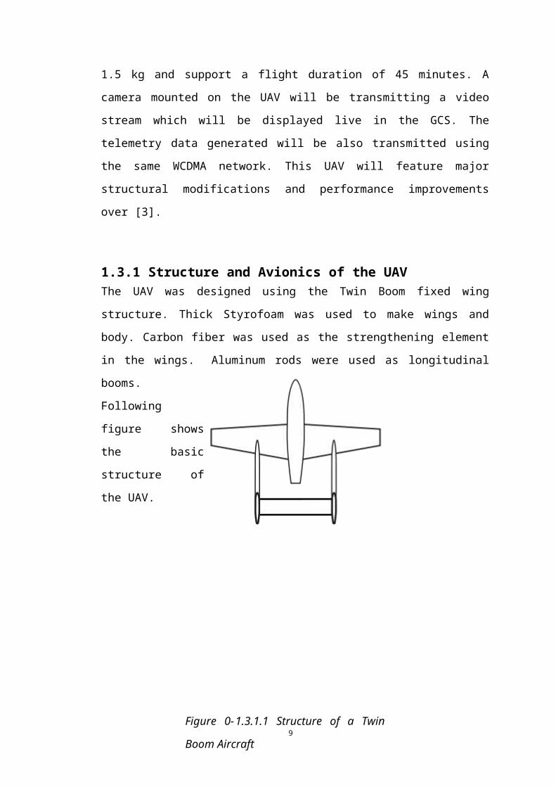
1.3.1 Structure and Avionics of the UAVThe UAV was designed using the Twin Boom fixed wing structure. Thick Styrofoam
was used to make wings and body. Carbon fiber was used as the strengthening
element in the wings. Aluminum rods were used as longitudinal booms. Following
figure shows the basic structure of the UAV.
The UAV is powered using a Li-Polymer battery and the propeller is situated in the
middle. Since the propeller is mounted in the middle of the fuselage, it is not damaged
in crash landings. Apart from that, this design ensures an unobstructed field-of-view
for any mounted camera.
Figure 0-1.3.1.1 Structure of a Twin Boom
Aircraft
6

A 8000 mAh, 6 cell battery will be used in this UAV. It will ensure higher endurance
and is expected to support 1 hour flight duration.
A modified version of an open hardware platform [4] was used to implement the
autopilot system. As the elementary functionality of this autopilot, it will be able to
follow a predefined path and initiate a return home or safe landing in adverse
situations. Maintaining the smooth movement in a dynamic environment will be
addressed so that the UAV will not experience stalling.
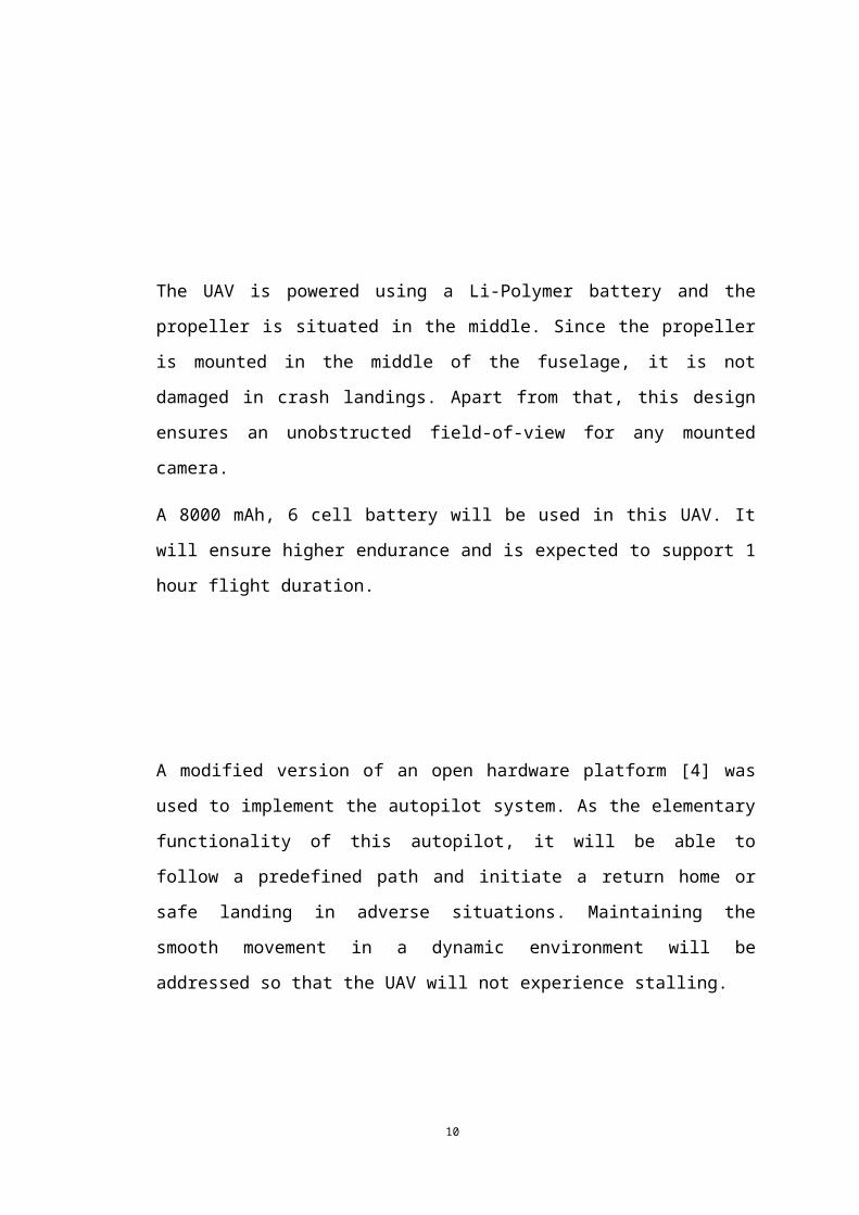
Figure 1.3.1.2 Autopilot System
The autopilot will be connected to a transmitter module, receiver module, sensors and
motor controllers. It will interact with a number of onboard sensors including Global
7
Positioning System sensor (GPS), barometer and air speed sensor. It will maintain a
continuous communication link with the GCS and send packets announcing its current
status.
8
1.3.2 Ground Control Station
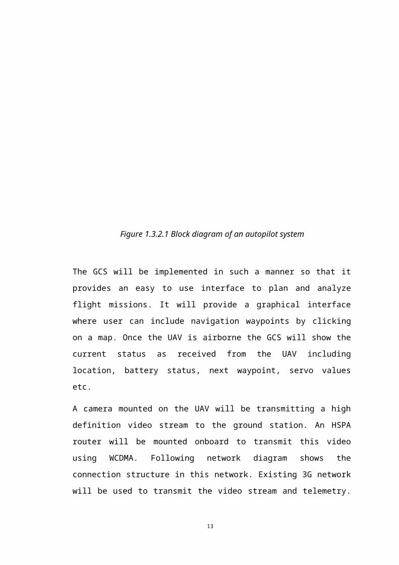
The GCS will be implemented in such a manner so that it provides an easy to use
interface to plan and analyze flight missions. It will provide a graphical interface
where user can include navigation waypoints by clicking on a map. Once the UAV is
airborne the GCS will show the current status as received from the UAV including
location, battery status, next waypoint, servo values etc.
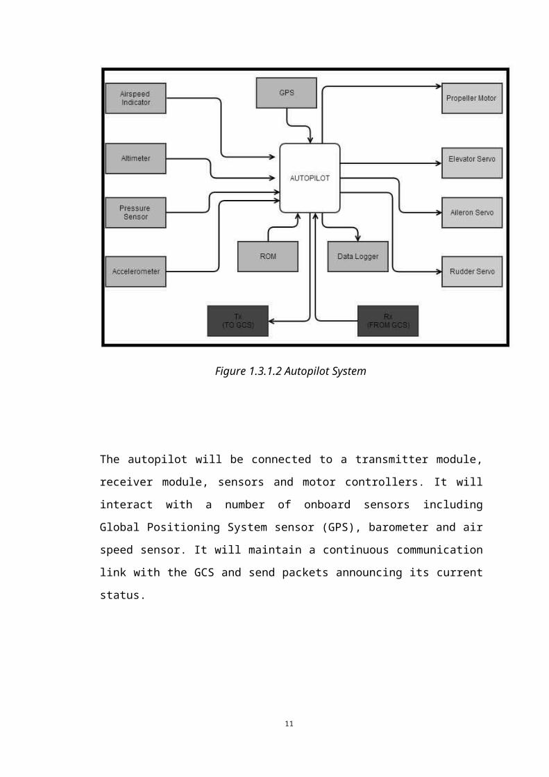
A camera mounted on the UAV will be transmitting a high definition video stream to
the ground station. An HSPA router will be mounted onboard to transmit this video
using WCDMA. Following network diagram shows the connection structure in this
network. Existing 3G network will be used to transmit the video stream and telemetry.
Typical radio modules will be used to transmit control signals to the UAV.
Figure 1.3.2.1 Block diagram of an autopilot system
9
1.4 Principal Results and Contributions
Several successful flight missions were carried out in the university premises and
outside.
Developing a UAV, with satisfactory endurance and achieving a 45 minute flight
duration can be considered as a major contribution to the local UAV industry. This is
a satisfactory duration to carry out a small range mission.
Feasibility of using WCDMA network to receive the live video from the on-board
camera and to receive telemetry data was tested during the project. Even though a
working prototype of the video link was implemented and tested during three flights,
the resulting video link cannot be recommended in mission-critical applications.
During flight tests, data were gathered to evaluate the performance of the WCDMA
network in higher altitudes.
Using WCDMA to receive telemetry was successful and is recommended in future
applications.
10
2. Developing UAV Structure
2.1 IntroductionOne of the major roles of developing an Unmanned Aerial Vehicle system is
constructing a well suitable structure which can fulfill the requirements of the project.
The stability, pay load, endurance, power profile and other characteristics of the UAV
depend on the structure.
Since this is an extension of previous year project, development of a much reliable
and stable structure was required. Lots of structural designs were analyzed and most
suitable two of them were chosen in order to carry out the project. Those two were
named as RAVAN (Robotics Aerial Vehicle with Autonomous Navigation) and G-23.
Raven was developed as the main airframe of the project while G-23 as to fulfill
testing purposes. G23 is a 1.5 scaled up version of previous year project. Structural
characteristics and capabilities of those two frames can be compared as followed.
RAVAN G23
Size Medium scale small scale
Propeller type pusher puller
Weight of the structure 5.5Kg 1.8Kg
Aerofoil shape Clerk y step
Strength higher medium
Table 2.1.1 Comparison of Ravan and G23
11
2.2 Design procedure of RAVAN structure
These types of UAV are more popular in UAV industry in the case of stability and the
safety of the sensors. Parts of the main airframe was designed and built one by one
very carefully.
Nose and main body are the parts of fuselage. Developments of those two are whole
different things. It is made of wood, covering films and fiber glass. Nose was build
using fiber glass while the main body was built using wood and covering films.
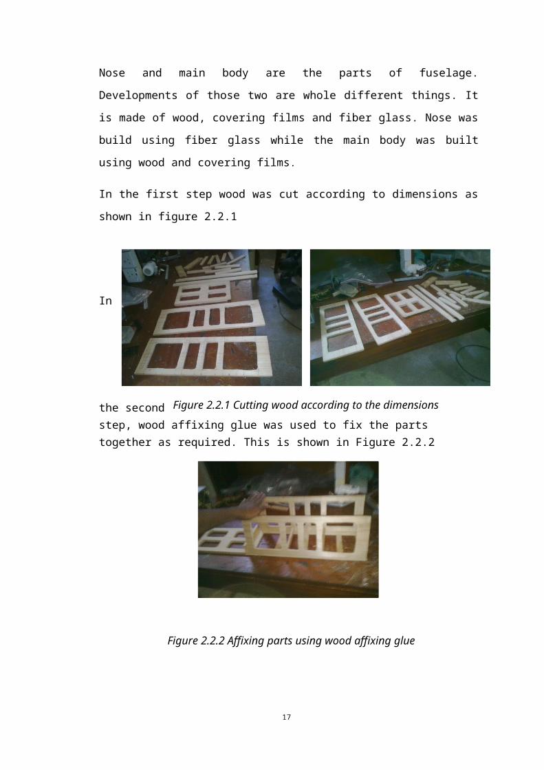
In the first step wood was cut according to dimensions as shown in figure 2.2.1
In the
second step, wood affixing glue was used to fix the parts together as required. This is shown in Figure 2.2.2
Figure 2.2.1 Cutting wood according to the dimensions
Figure 2.2.2 Affixing parts using wood affixing glue
12
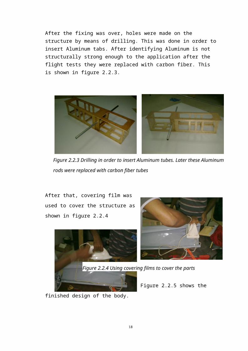
After the fixing was over, holes were made on the structure by means of drilling. This was done in order to insert Aluminum tabs. After identifying Aluminum is not structurally strong enough to the application after the flight tests they were replaced with carbon fiber. This is shown in figure 2.2.3.
After that, covering film was used to cover the structure as shown in figure 2.2.4
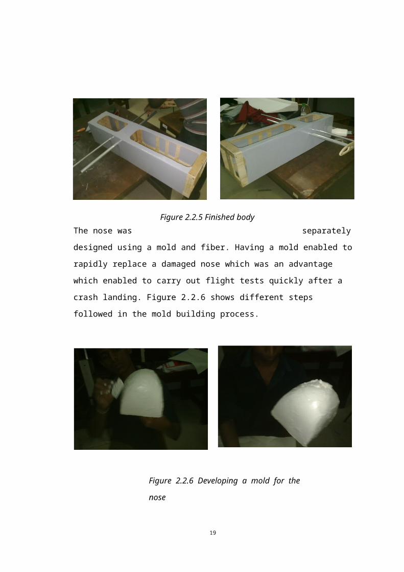
Figure 2.2.5 shows the finished design of the body.
Figure 2.2.3 Drilling in order to insert Aluminum tubes. Later these Aluminum rods
were replaced with carbon fiber tubes
Figure 2.2.4 Using covering films to cover the parts
13
The nose was separately designed using a mold and fiber. Having a mold enabled to
rapidly replace a damaged nose which was an advantage which enabled to carry out
flight tests quickly after a crash landing. Figure 2.2.6 shows different steps followed
in the mold building process.
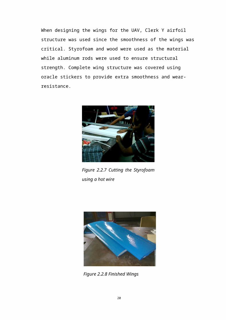
When designing the wings for the UAV, Clerk Y airfoil structure was used since the
smoothness of the wings was critical. Styrofoam and wood were used as the material
while aluminum rods were used to ensure structural strength. Complete wing structure
was covered using oracle stickers to provide extra smoothness and wear-resistance.
Figure 2.2.6 Developing a mold for the nose
Figure 2.2.7 Cutting the Styrofoam
using a hot wire14
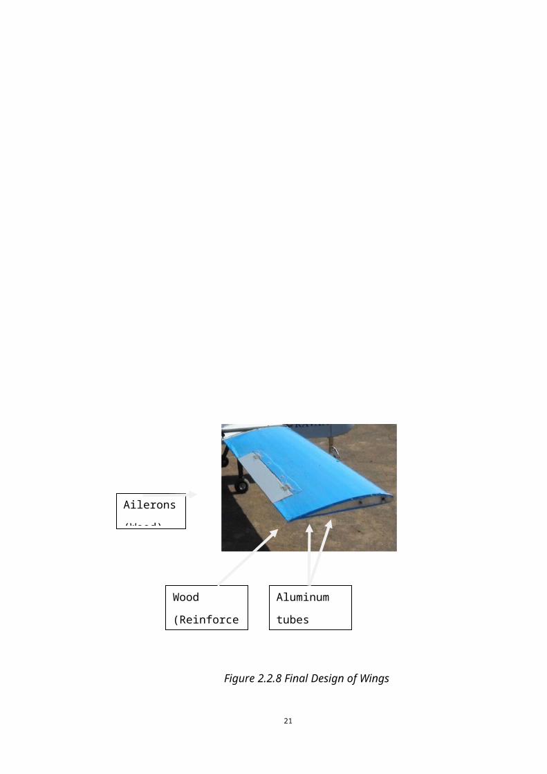
Ailerons
(Wood)
Figure 2.2.8 Finished Wings
15
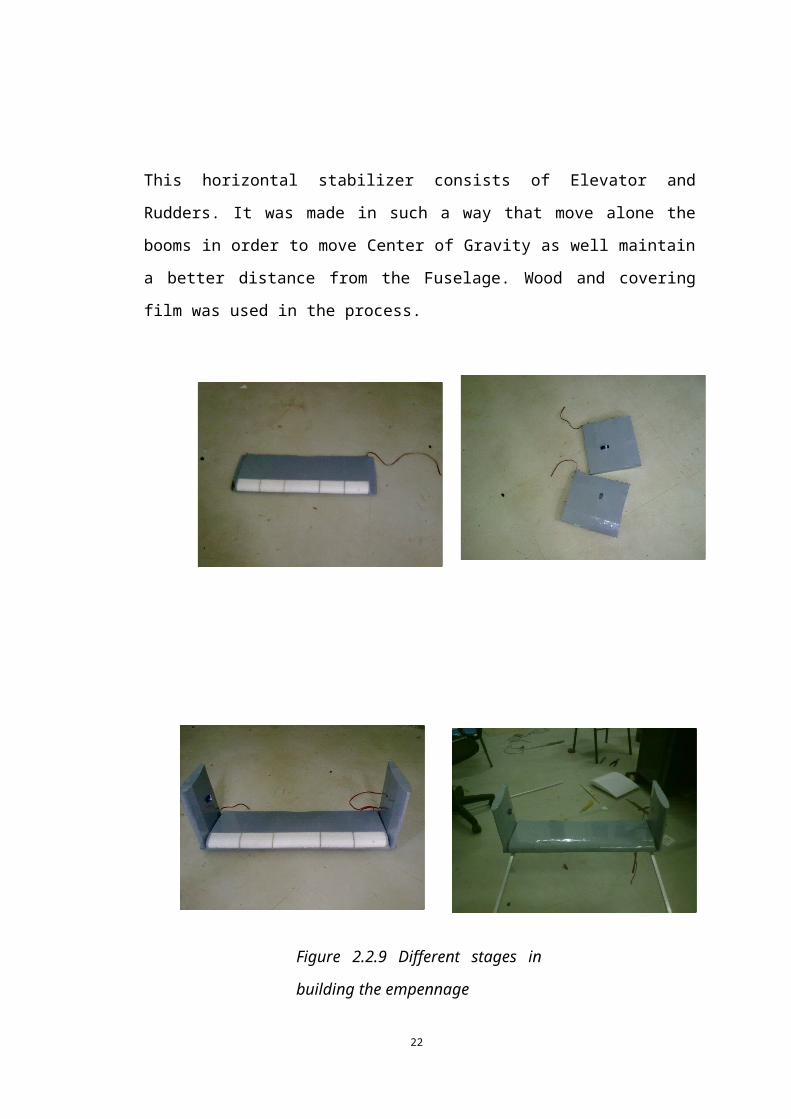
This horizontal stabilizer consists of Elevator and Rudders. It was made in such a way
that move alone the booms in order to move Center of Gravity as well maintain a
better distance from the Fuselage. Wood and covering film was used in the process.
Figure 2.2.8 Final Design of Wings
Figure 2.2.9 Different stages in
building the empennage
16
Landing gear plays a major role in the development process of UAVs because it
should be made with much strength. Some parts of the landing gear and nose gear
were imported and others were made at the university.
Carbon fiber, rubber, aluminum tubes and white iron tubes were used.
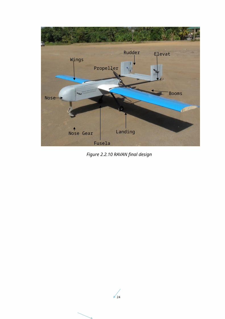
Figure 2.2.10 shows the final design of RAVAN UAV. Figure 2.2.11 shows the final design of G23
White Iron
Aluminum
Tubes
Sprin
gHard
Drive
Figure2.2.10 Final Design of Landing Gears
17
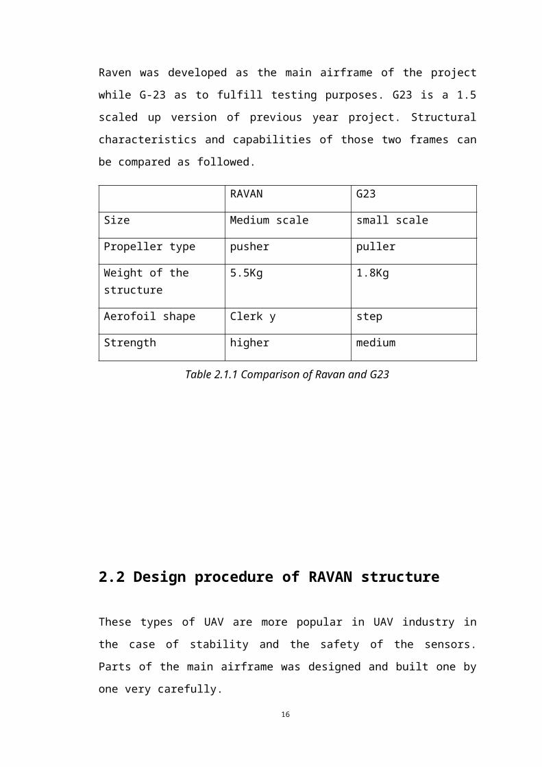
Figure 2.2.10 RAVAN final design
Wings
Rudders Elevator
Landing GearNose Gear
Propeller
Nose
Fuselage
Booms
Rudder
Elevator18
19
3. Avionics and Flight Analysis
3.1 RAVAN UAV
3.1.1 - configuration
Plane type – Twin Boom pusher plane
Main wing aerofoil Clark y 11
Main wing span 8 .5’
Material Wood ,fiberglass ,Styrofoam, carbon fiber ,metal ,covering film
Weight of plane 6.885 kg
MTOW 9.885 kg
Power Electric power with LIPO battery
Endurance 35 minute
Table 3.1.1.1 Configuration of RAVAN
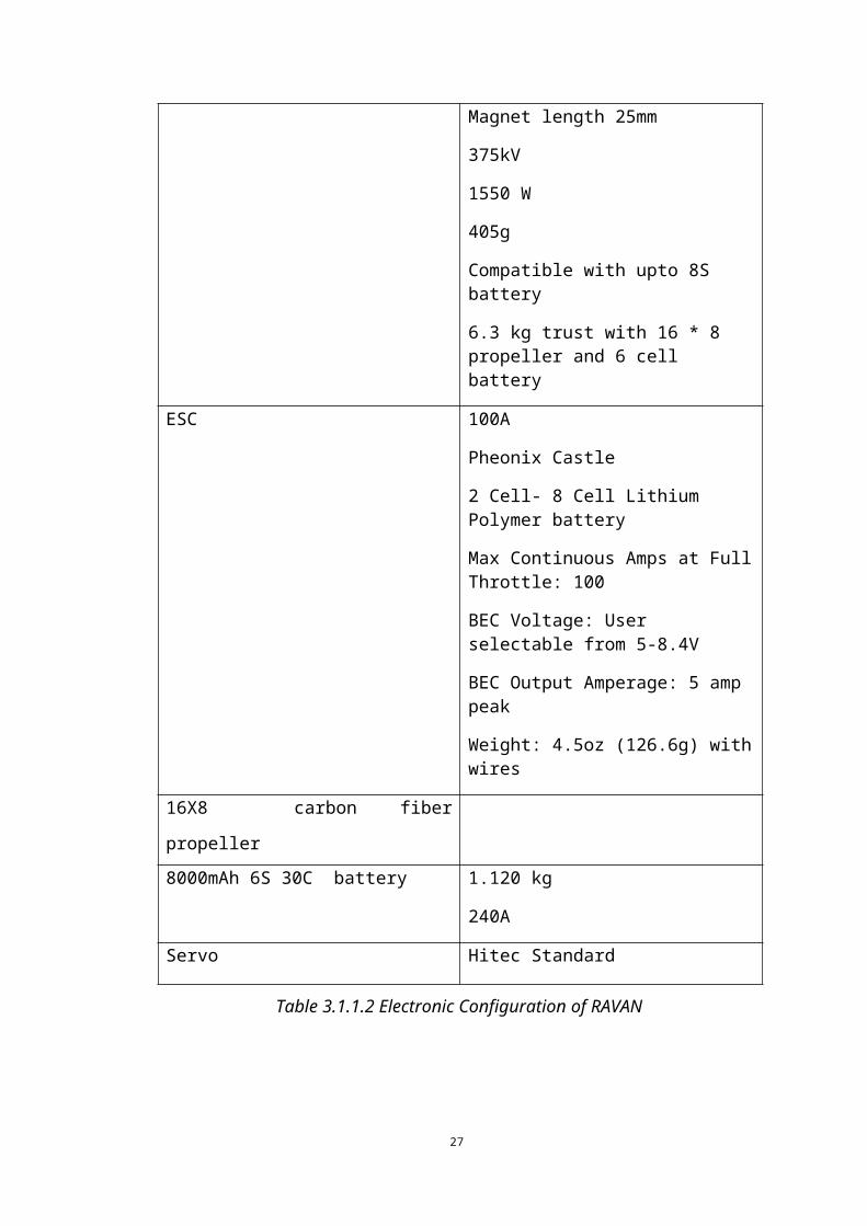
3.1.2 Electronic configuration
5025 1550W OS motor OMA-5025-375
.50 Size
Rotor Diameter 50mm
Magnet length 25mm
375kV
1550 W
405g
Compatible with upto 8S battery
20
6.3 kg trust with 16 * 8 propeller and 6 cell battery
ESC 100A
Pheonix Castle
2 Cell- 8 Cell Lithium Polymer battery
Max Continuous Amps at Full Throttle: 100
BEC Voltage: User selectable from 5-8.4V
BEC Output Amperage: 5 amp peak
Weight: 4.5oz (126.6g) with wires
16X8 carbon fiber propeller
8000mAh 6S 30C battery 1.120 kg
240A
Servo Hitec Standard
Table 3.1.1.2 Electronic Configuration of RAVAN
21
3.2 G23 aircraft
3.2.1 UAV Configuration
Plane type – BLU baby
Main wing aerofoil Step wing
Main wing span 6 ‘
Material KT Board ,Styrofoam , Oracle sticker, carbon fiber ,wood
Weight of plane 2.35kg
MTOW 3.55 kg
Power Electric power with LIPO battery
Endurance 10 minute
Table 3.2.1.1 G23 UAV configuration
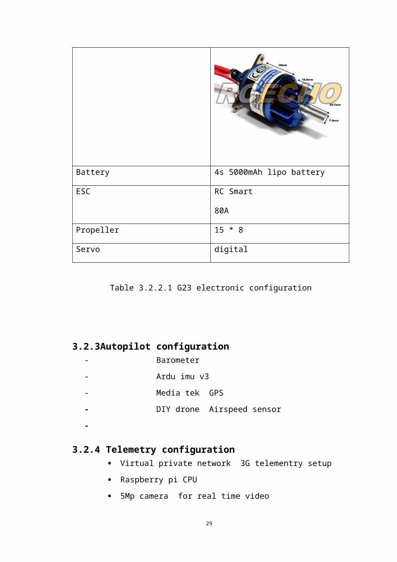
3.2.2. Electronic configuration
Motor RC Smart
790 kV
22
Battery 4s 5000mAh lipo battery
ESC RC Smart
80A
Propeller 15 * 8
Servo digital
Table 3.2.2.1 G23 electronic configuration
3.2.3Autopilot configuration - Barometer
- Ardu imu v3
- Media tek GPS
- DIY drone Airspeed sensor
-
3.2.4 Telemetry configuration Virtual private network 3G telementry setup
Raspberry pi CPU
5Mp camera for real time video
23
3.3 Flight test and summarized results
3.3.1 RAVAN UAV maiden flight
The maiden flight of RAVAN UAV was carried out on 18th August 2013 at
University of Moratuwa grounds. Total takeoff weight was 5.95 kg. Some important
configurations were as follows.
● 80A 6s Aeolian ESC
● 1885 W Aeolian motor
● 4S 5200mAh battery
● 16X8 gas propeller
Plane was airborne very quickly due to high incident angle. Therefore the plane
hadn’t enough airspeed to be stable once it airborne. Pitch angle increase so much and
pilot cutoff the throttle. Plane went nose-down and suddenly crashed.
A crash analysis was performed using photographs as well as flight logs.
Visually inspecting the video frame showed that abnormal low speed takeoff has
happened due to high incident angle of wings (18° incident angle)
Figure 3.3.1.1. Crash analysis
24
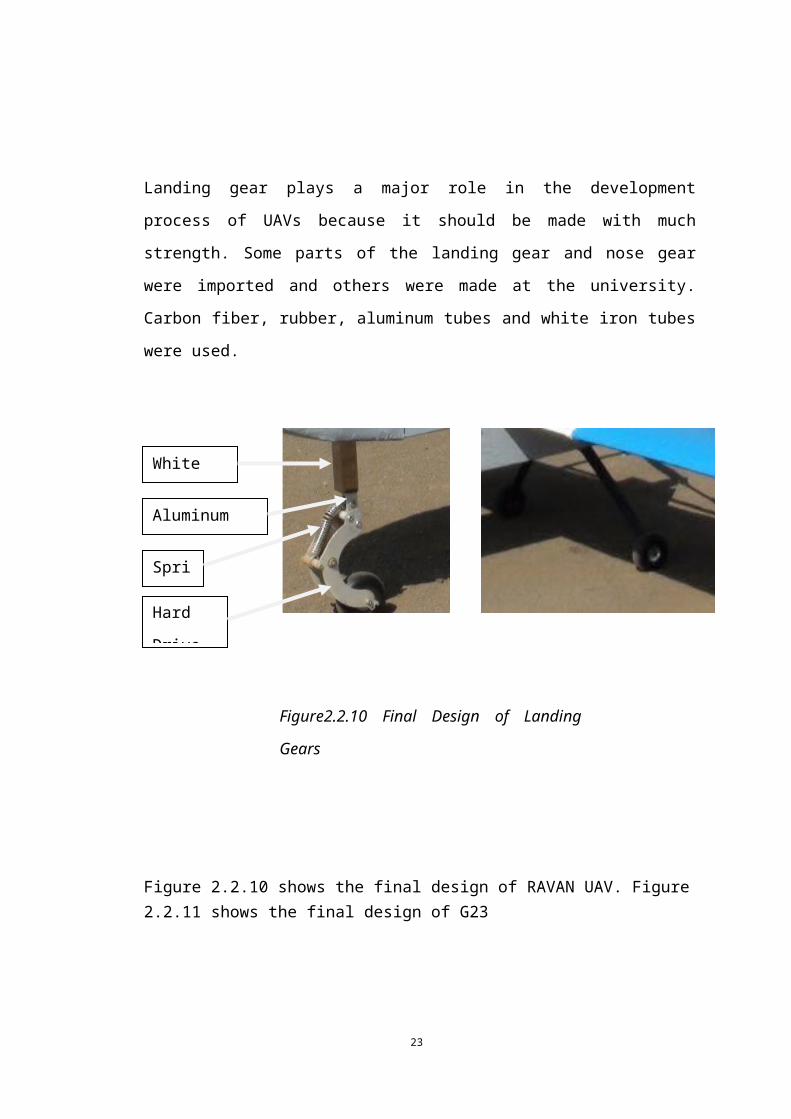
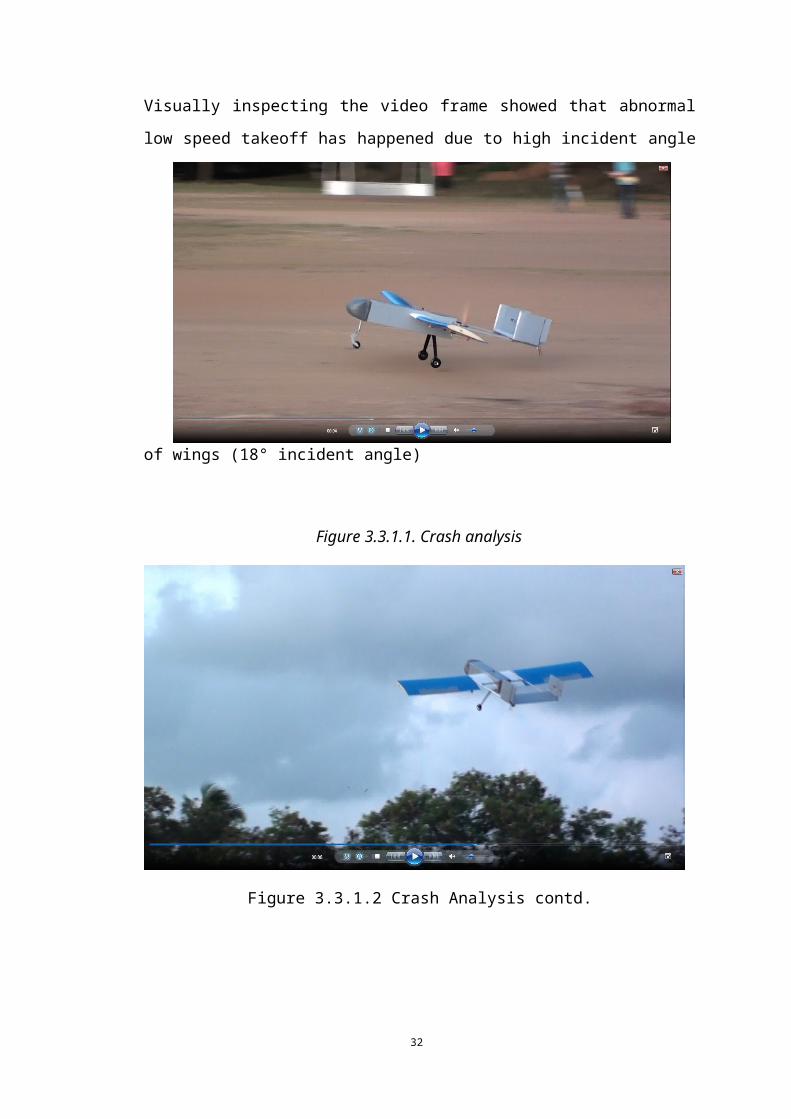
Figure 3.3.1.2 Crash Analysis contd.
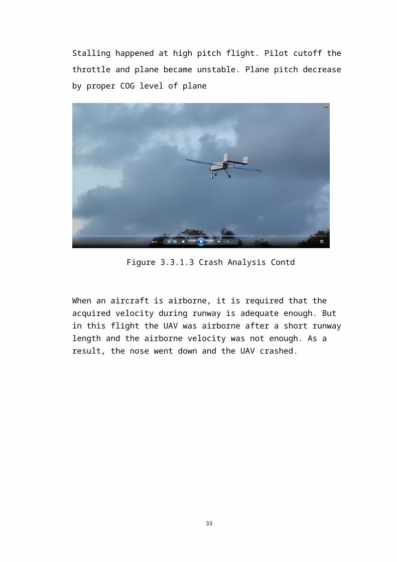
Stalling happened at high pitch flight. Pilot cutoff the throttle and plane became
unstable. Plane pitch decrease by proper COG level of plane
Figure 3.3.1.3 Crash Analysis Contd
When an aircraft is airborne, it is required that the acquired velocity during runway is adequate enough. But in this flight the UAV was airborne after a short runway length
25
and the airborne velocity was not enough. As a result, the nose went down and the UAV crashed.
Figure 3.3.1.4 Crash Analysis Contd.
Figure 3.3.1.5. Crash Analysis Contd.
Identification of issues of plane structure
The incident angle was too high and the UAV was airborne within
20m runway
Empennage will lift up due to trust produced by the propeller
26
Twin booms are not much strength and deform when the pitch up
Wing deformed at the take off stage
After the analysis the following changes were made.
Incident angle of wings was decreased
Horizontal stabilizer airfoil profile was changed to a flat profile(insert
image)
Wing strength increased by using two spars instead of one
Motor and battery upgrade
Structural strength was increased by using carbon fiber instead of
aluminum rods.
XFLR5 was used to analyze the aerodynamics of the frame. It is an analysis tool for
airfoils, wings and planes operating at low Reynolds Numbers. XFLR5 includes
XFoil's Direct and Inverse analysis capabilities and wing design and analysis
capabilities based on the Lifting Line Theory, Vortex Lattice Method, and 3D Panel
Method.
Following key issues were identified on the present structure.
* Stalling effect at low alpha angle (3.00°)
27
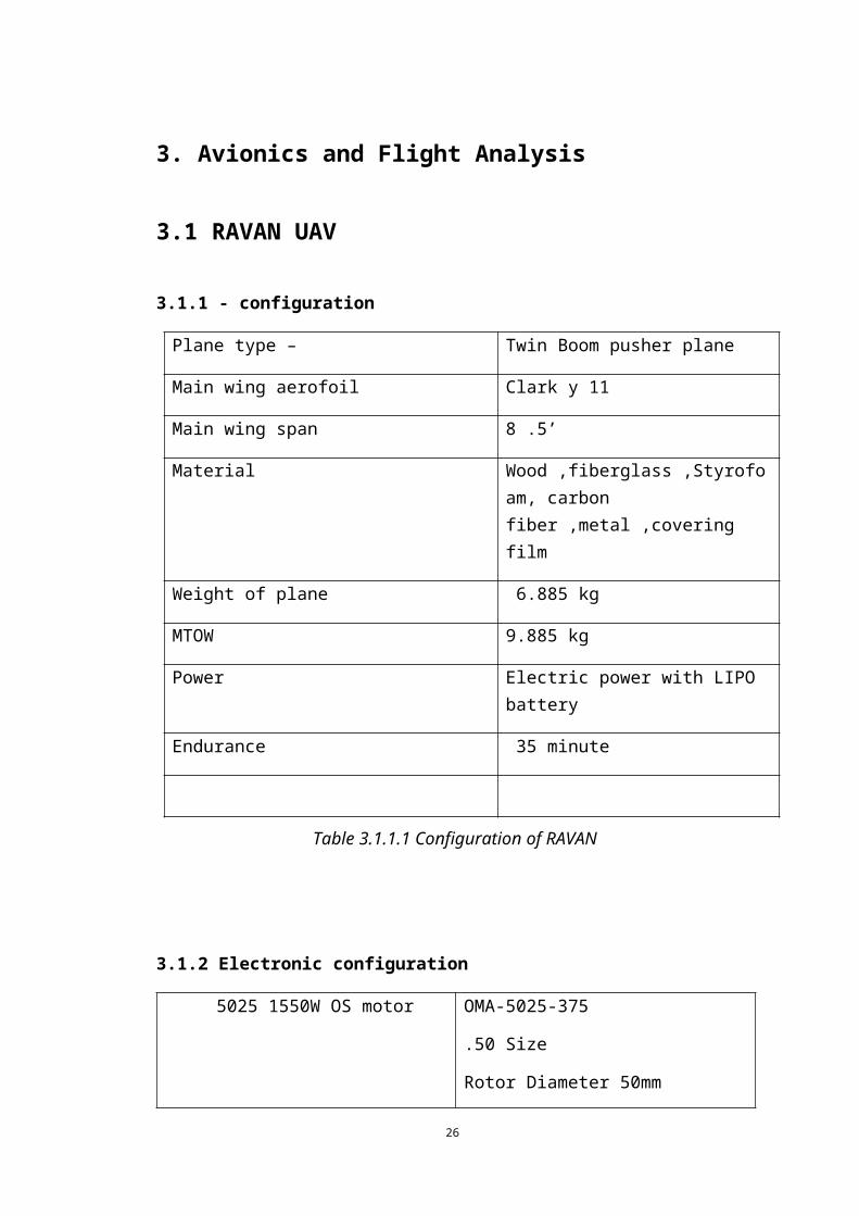
Figure 3.3.1.6 Structural Analysis Using XFLR5
Above diagram is used to analyze the relationship between alpha and pressure
coefficient Cp.Typically the pitching moment read arrow should be above X axis for
being stable at given alpha angle .
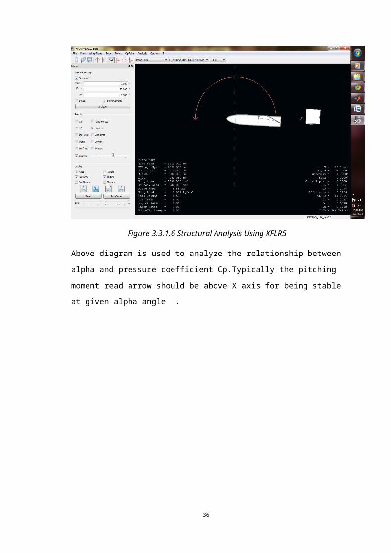
Figure 3.3.1.7 Crash Analysis using XFLR5 contd.
28
The above diagram shows how XFLR5 has been used to analyze the lift, drag and center of pressure.
Graph analysis
Figure 3.3.1.8 Graph Analysis
As shown in the above figure, the plot between alpha and Cm should be equal to the
one shown in the left. The resulting plots we got from analyzing our structure shows
that the shape of the plot is apparently similar. However we can make it more accurate
by changing the angle of incident.
29
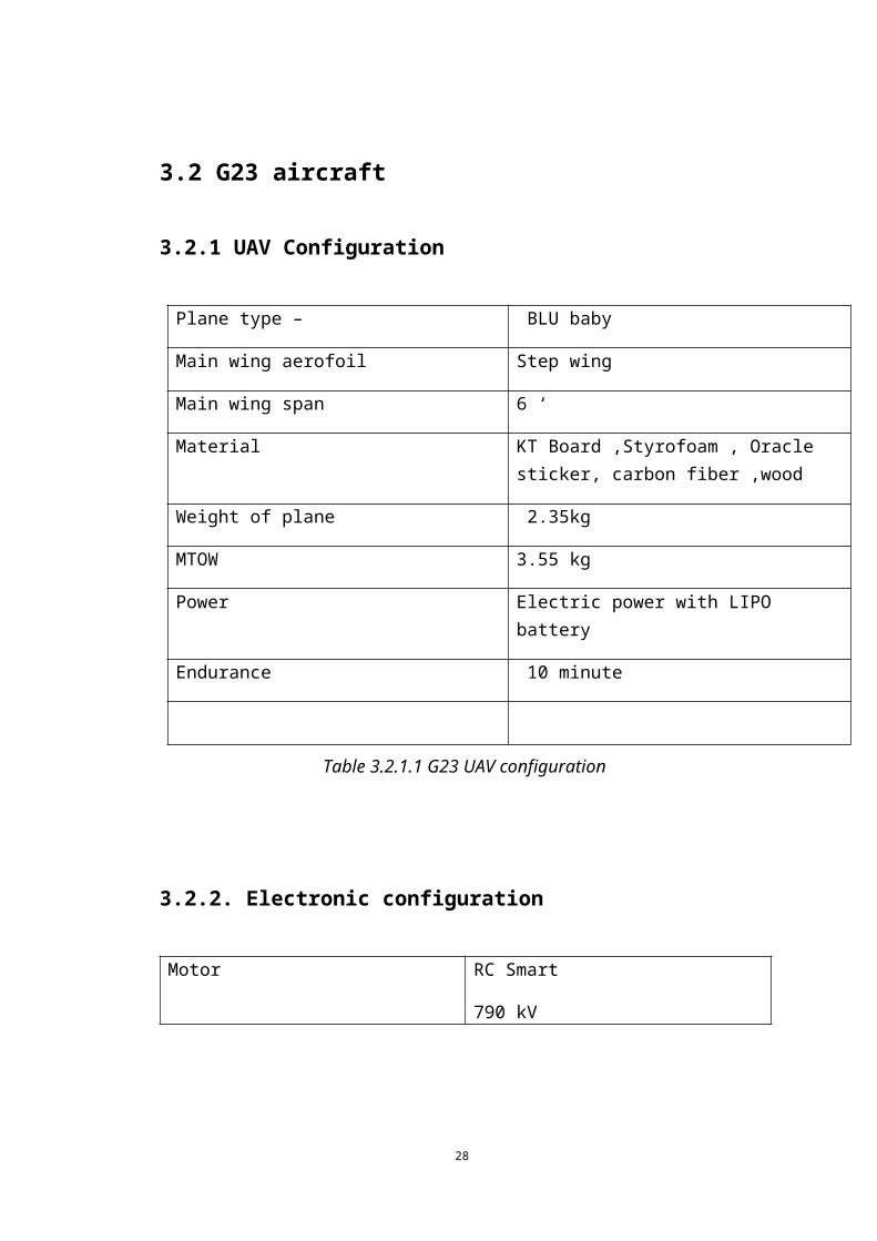
Figure 3.3.1.9Flight analysis using XFLR5
After analysis was done angle of incident was changed to 5° and reanalysis was
carried out on XFLR5.
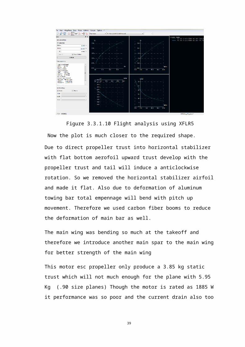
Figure 3.3.1.10 Flight analysis using XFLR5
Now the plot is much closer to the required shape.
Due to direct propeller trust into horizontal stabilizer with flat bottom aerofoil upward
trust develop with the propeller trust and tail will induce a anticlockwise rotation. So
we removed the horizontal stabilizer airfoil and made it flat. Also due to deformation
30
of aluminum towing bar total empennage will bend with pitch up movement.
Therefore we used carbon fiber booms to reduce the deformation of main bar as well.
The main wing was bending so much at the takeoff and therefore we introduce
another main spar to the main wing for better strength of the main wing
This motor esc propeller only produce a 3.85 kg static trust which will not much
enough for the plane with 5.95 Kg (.90 size planes) Though the motor is rated as
1885 W it performance was so poor and the current drain also too high limiting the
endurance .So we change our electronics configuration as follows
100A Phoenix castle ESC
5025 1550W OS motor
16X8 carbon fiber propeller
8000mAh 6S battery
With all of this electronics and other modification total weight of the RAVAN
become 6.885 Kg and total flight time increases to 35 minute as well .Also It can
carry up to 2kg payload as well
31

3.3.2 G23 maiden flight
Date: 12/11/2013
Venue: University playground
Total takeoff weight: 2.35 kg
Results
Plane was stable flight with low speed with the 12X4.5 propeller and didn’t have
much throttle to pitch up. Due to step wing airfoil the UAV didn’t have much
aerodynamic lift so plane almost flew with 100% throttle.
So we changed propeller to 15X8E electric propeller and plane had enough propulsion
to have airborne with sustainable airspeed and we achieve 150m altitude with the
airplane with current configuration (previous G22 had 80m-90m maximum ceiling)
3.3.3 G23 third flight Date: 10/12/2013
Venue: Universities playground
Total takeoff weight: 2.65 kg
Flight Expectations: Autopilot system was integrated to the system and plan to engage
stabilize mode and Fly by wire A mode
Plane was airborne with good airspeed and once we achieve the enough altitude to
engage the stabilize mode we engage stabilize mode and plane had stabilize with
little roll and a little nose down configuration ,but plane does not oscillate around
any axis .So we engage the FLY BY wire A Plane nose down suddenly crash down
with broken left wing
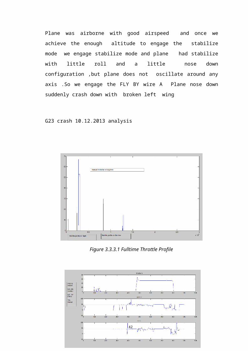
G23 crash 10.12.2013 analysis
32
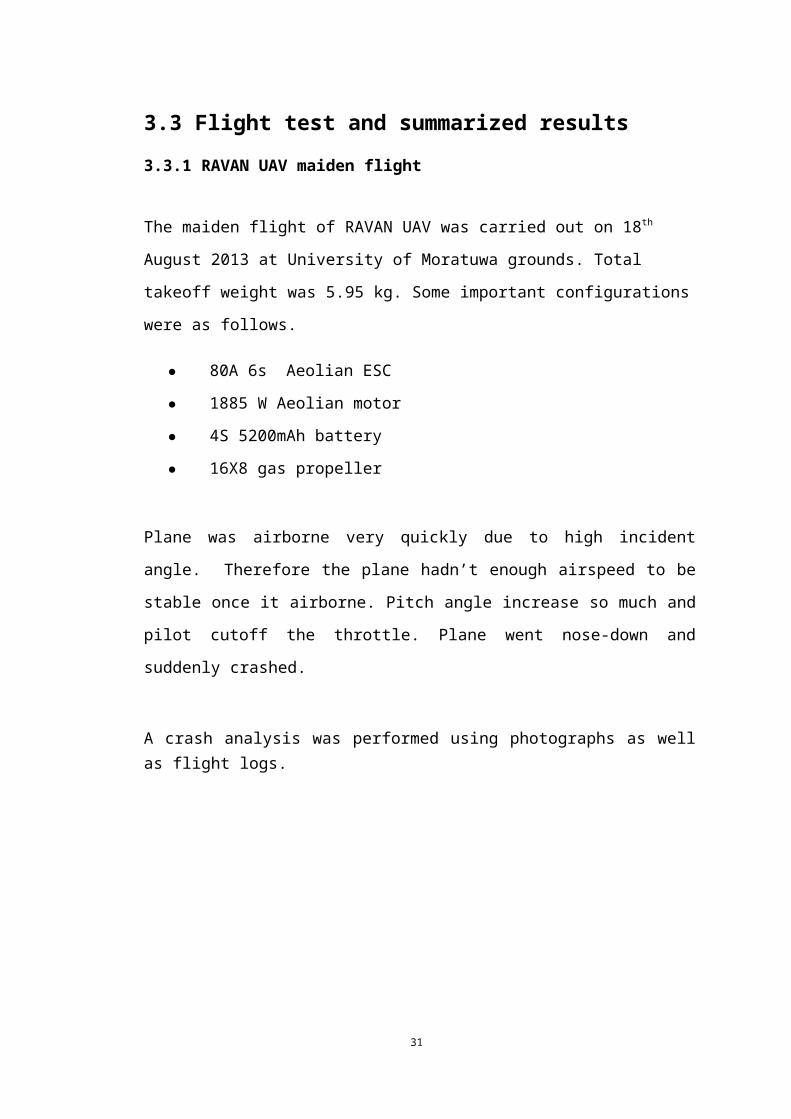
Figure 3.3.3.1 Fulltime Throttle Profile
Figure 3.3.3.2. Full time input profile
33
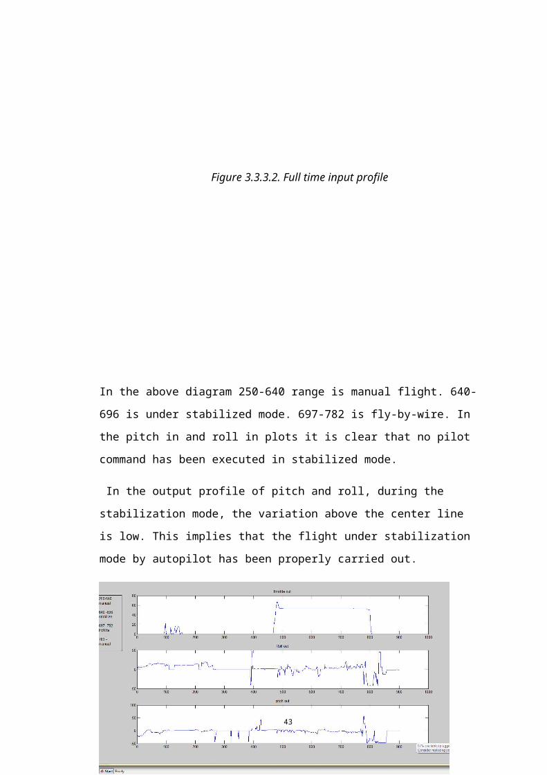
In the above diagram 250-640 range is manual flight. 640-696 is under stabilized
mode. 697-782 is fly-by-wire. In the pitch in and roll in plots it is clear that no pilot
command has been executed in stabilized mode.
In the output profile of pitch and roll, during the stabilization mode, the variation
above the center line is low. This implies that the flight under stabilization mode by
autopilot has been properly carried out.
Figure 3.3.3.3. full time output profile
34
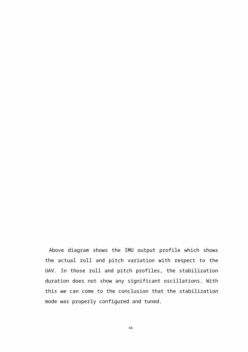
Above diagram shows the IMU output profile which shows the actual roll and pitch
variation with respect to the UAV. In those roll and pitch profiles, the stabilization
duration does not show any significant oscillations. With this we can come to the
conclusion that the stabilization mode was properly configured and tuned.
Full flight roll profile
35
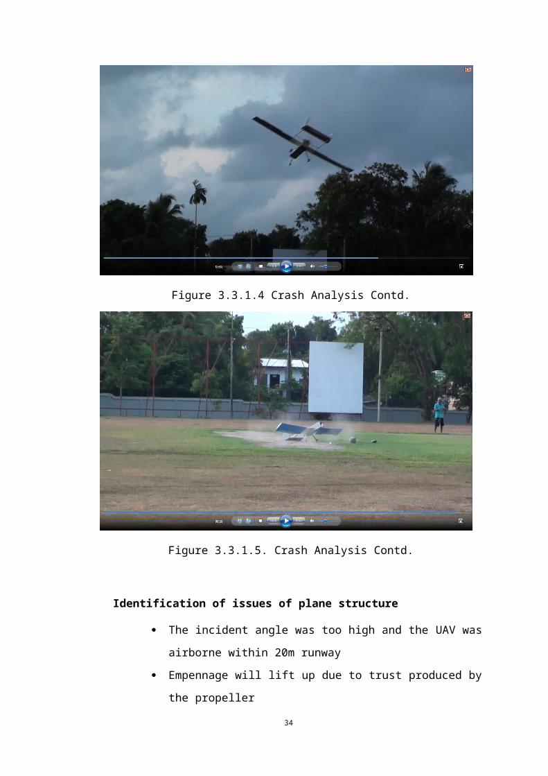
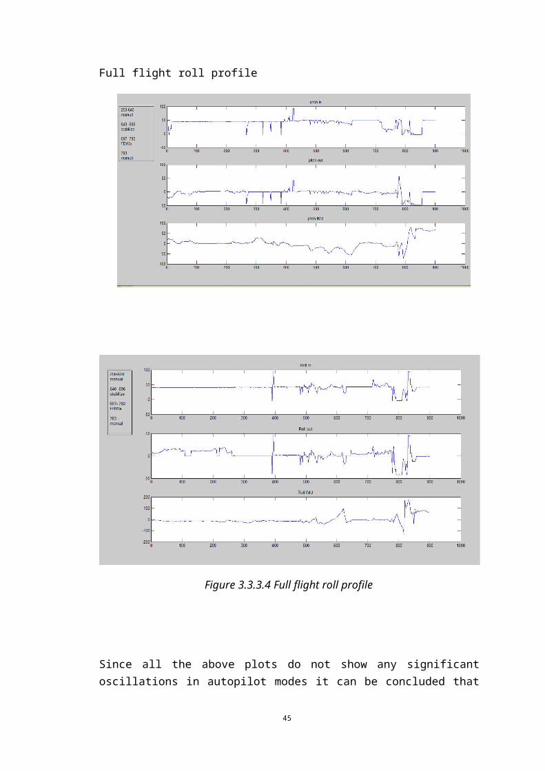
Figure 3.3.3.4 Full flight roll profile
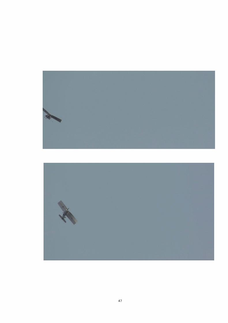
Since all the above plots do not show any significant oscillations in autopilot modes it can be concluded that the reason for the crash was not related to any issue with the autopilot system.
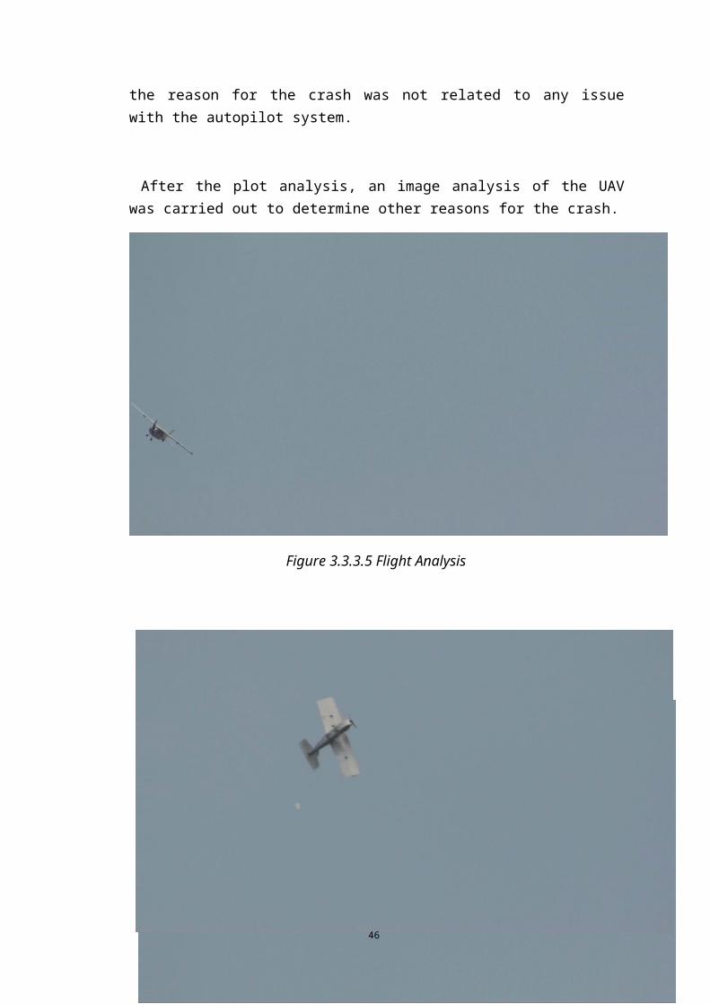
After the plot analysis, an image analysis of the UAV was carried out to determine other reasons for the crash.
36
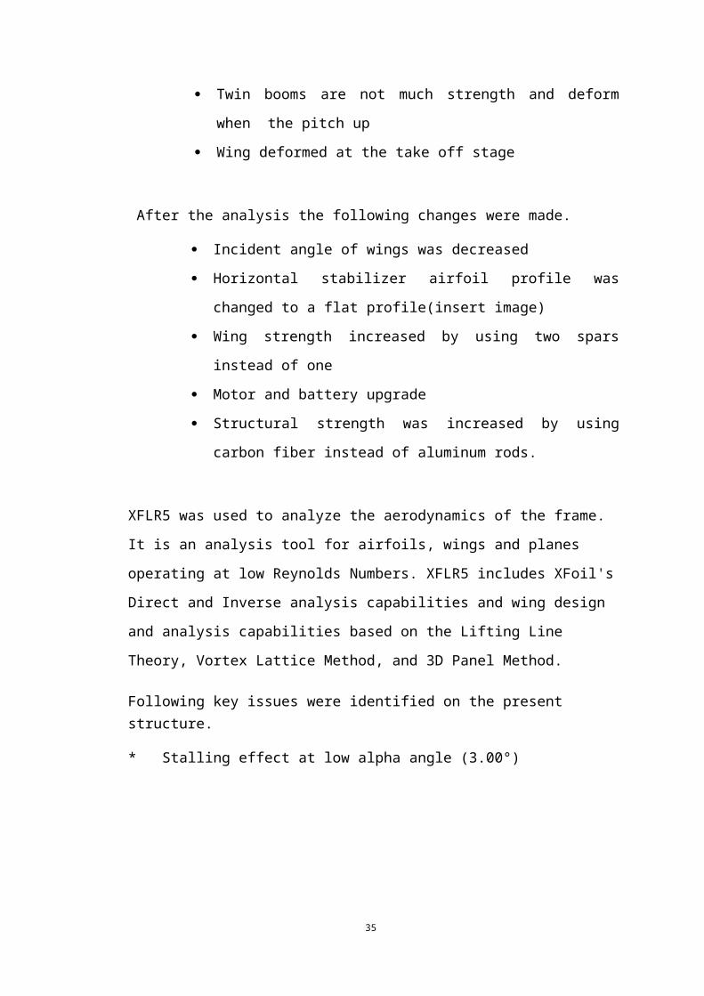
Figure 3.3.3.5 Flight Analysis
37
38
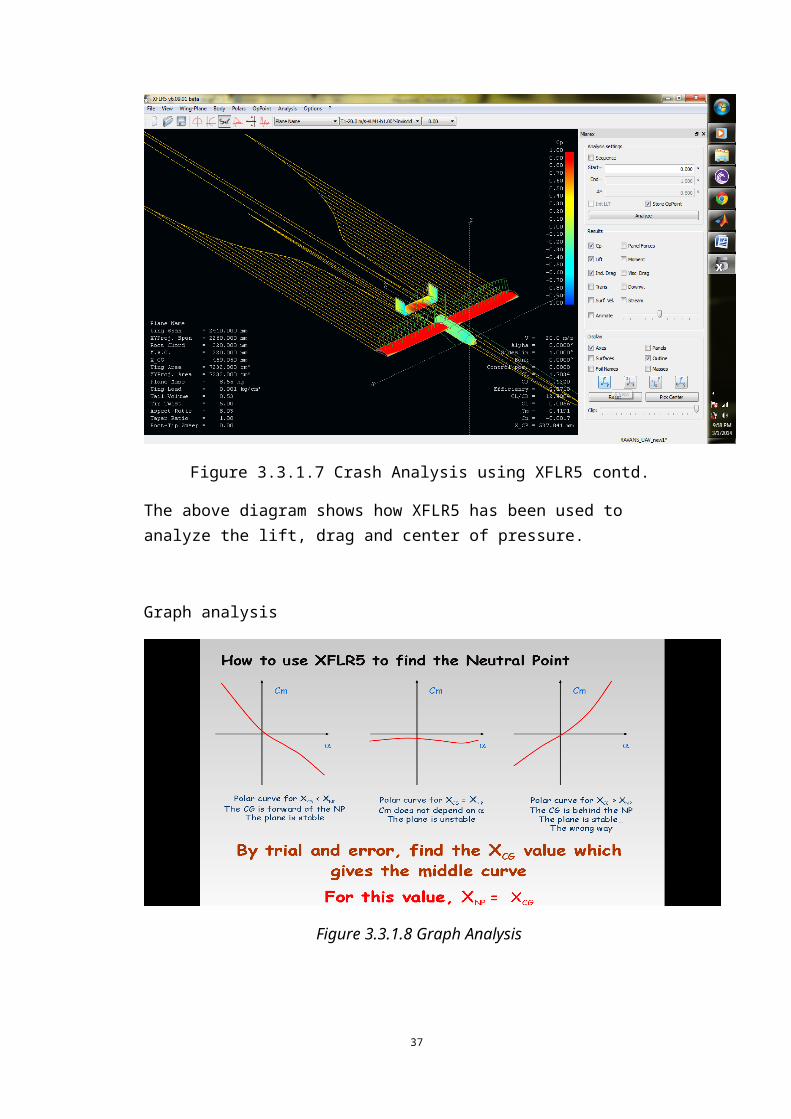
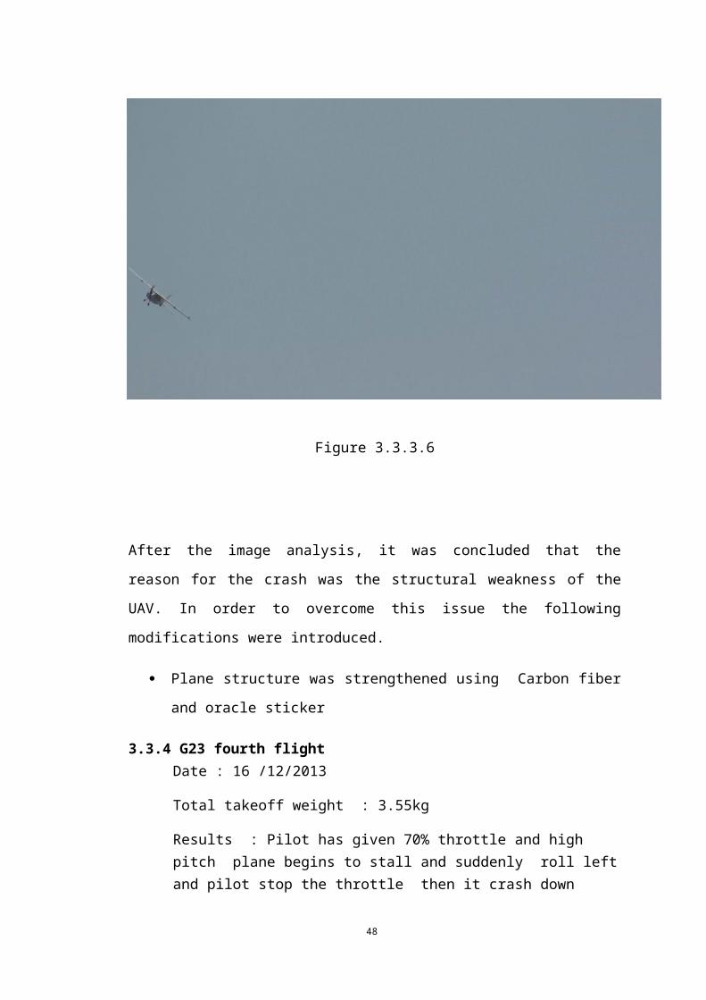
Figure 3.3.3.6
After the image analysis, it was concluded that the reason for the crash was the
structural weakness of the UAV. In order to overcome this issue the following
modifications were introduced.
Plane structure was strengthened using Carbon fiber and oracle sticker
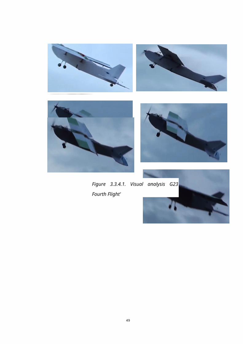
3.3.4 G23 fourth flight Date : 16 /12/2013
Total takeoff weight : 3.55kg
Results : Pilot has given 70% throttle and high pitch plane begins to stall and suddenly roll left and pilot stop the throttle then it crash down
39
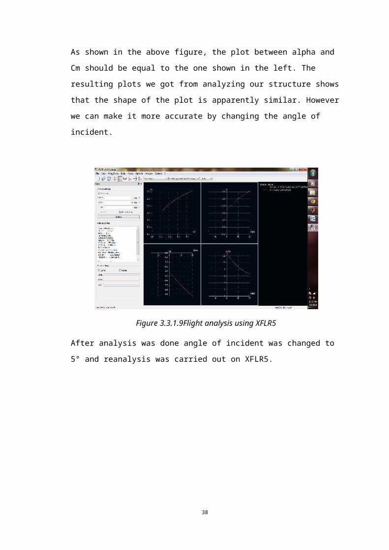
Figure 3.3.4.1. Visual analysis G23 Fourth
Flight'
40
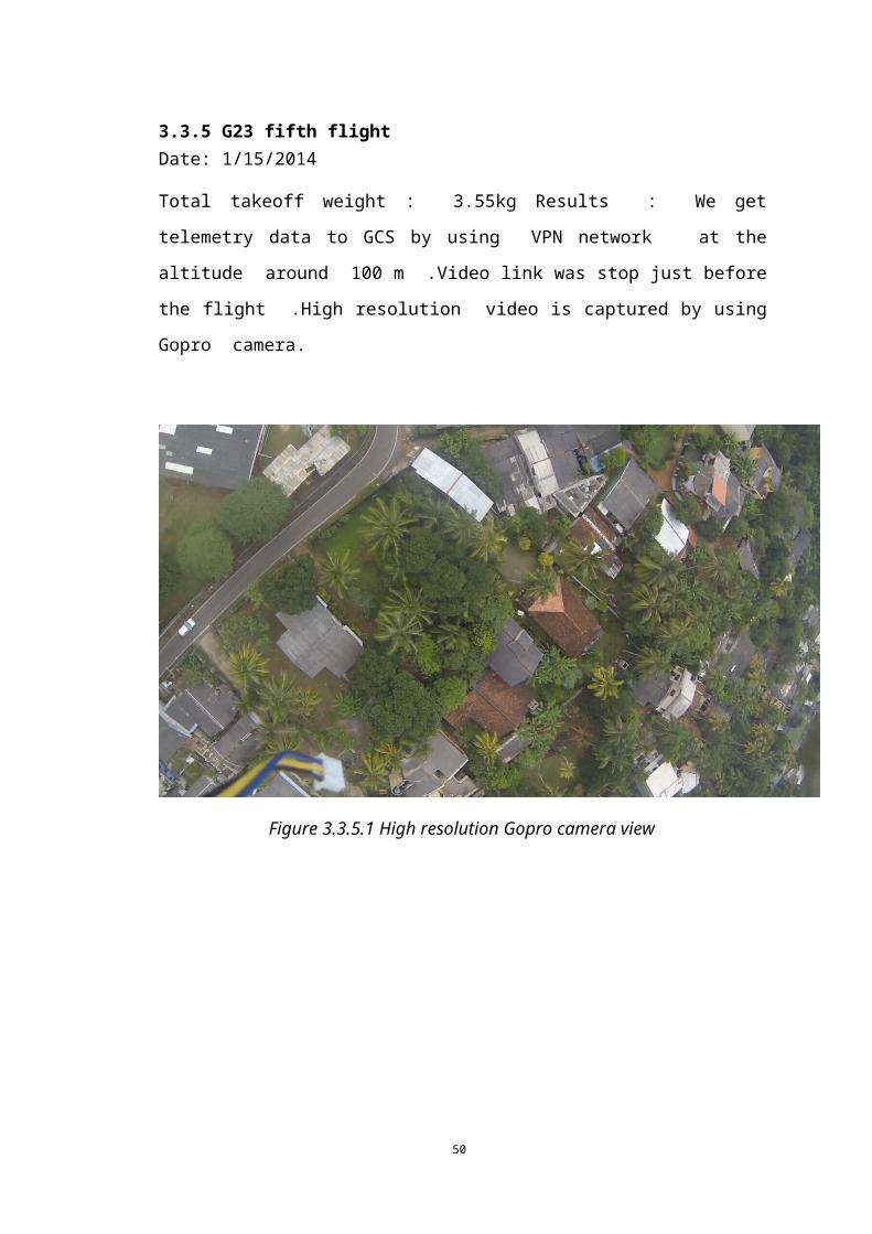
3.3.5 G23 fifth flight Date: 1/15/2014
Total takeoff weight : 3.55kg Results : We get telemetry data to GCS by using VPN
network at the altitude around 100 m .Video link was stop just before the
flight .High resolution video is captured by using Gopro camera.
Figure 3.3.5.1 High resolution Gopro camera view
41
4. Autopilot System
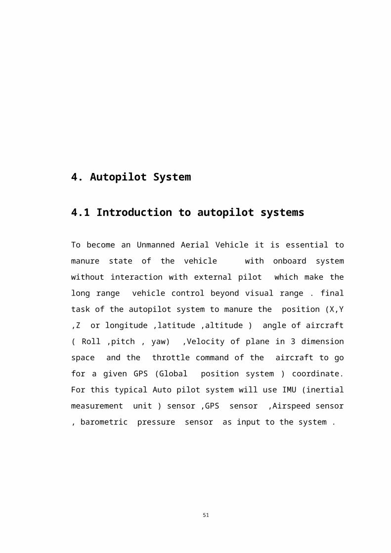
4.1 Introduction to autopilot systems
To become an Unmanned Aerial Vehicle it is essential to manure state of the vehicle
with onboard system without interaction with external pilot which make the long
range vehicle control beyond visual range . final task of the autopilot system to
manure the position (X,Y ,Z or longitude ,latitude ,altitude ) angle of aircraft
( Roll ,pitch , yaw) ,Velocity of plane in 3 dimension space and the throttle
command of the aircraft to go for a given GPS (Global position system ) coordinate.
For this typical Auto pilot system will use IMU (inertial measurement unit )
sensor ,GPS sensor ,Airspeed sensor , barometric pressure sensor as input to the
system .
Figure 4.1.1. Autopilot introduction
42
43
4.2 Main actuators in UAV
Ailerons - control the rolling of UAV
Elevator – Control the pitch of UAV
Rudder – Control the yaw axis rotation
In this project we have used open source Ardupilot algorithms on pre design
autopilot board by 08th batch which was used by previous group as well ,In this
chapter we will go for normal setup method of system and for more detail of the
system can find from previous group report . Autopilot algorithm is consist of four
basic function
Initializing system
Fast loop
Medium loop
Slow loop
Figure 4.2.1 Actuators in a UAV
44
4.3 Initialization system
Once autopilot algorithm start up the first stage of the system is to initializing system
with input command and other data programmed by GCS .Begin of the system
initializing will show by actuating of aileron, elevator, and rudder with some rhythm
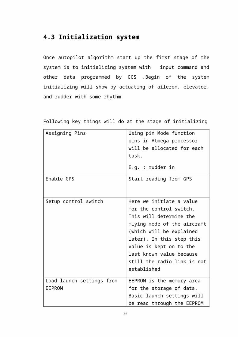
Following key things will do at the stage of initializing
Assigning Pins Using pin Mode function pins in Atmega processor will be allocated for each task.
E.g. : rudder in
Enable GPS Start reading from GPS
Setup control switch Here we initiate a value for the control switch. This will determine the flying mode of the aircraft (which will be explained later). In this step this value is kept on to the last known value because still the radio link is not established
Load launch settings from EEPROM EEPROM is the memory area for the storage of data. Basic launch settings will be read through the EEPROM
Connect to radio Start communicating with the radio link. This is the link which we use to manually control the airplane
Setup PWM timers
Print radio This will start the serial data reading of the radio communication link Set the correct flight mode
Table 4.3.1 Initializing stage activities
45
After system initializing done it will regenerate some command for controlling
actuators in a rhythm indicating system initialized. Also we check the IMU indicator
lights also to check IMU initialized or not
After initializing happened system will loop 3 loops called fast loop, medium loop
and slow loop,
The major idea behind the three separate loop is to assigning more time for more
important input and more important calculations priority low important calculations
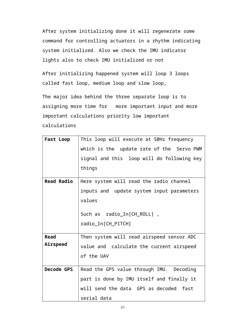
Fast Loop This loop will execute at 50Hz frequency which is the update
rate of the Servo PWM signal and this loop will do following
key things
Read Radio Here system will read the radio channel inputs and update
system input parameters values
Such as radio_In[CH_ROLL] , radio_In[CH_PITCH]
Read Airspeed Then system will read airspeed sensor ADC value and calculate
the current airspeed of the UAV
Decode GPS Read the GPS value through IMU. Decoding part is done by
IMU itself and finally it will send the data GPS as decoded fast
serial data
Calculate Altitude Error
This will hold the altitude for the aircraft in the auto mode. IT
will read the BMP085 barometric sensor value from IMU data.
We assign altitudes for the aircraft when we are assigning
waypoints in the initial stages of the launching.
Calculate Bearing Error
This will calculate the error in our heading, based on the next waypoint which we must be reaching
Update Current Flight Mode
This will tell what aircraft has to do base on the flight mode that the aircraft in now positioned. Stabilize The mode will determined by reading radio channel 6 by another separate processor (AT_tiny45) because system is need to run in independent in Autopilot mode and manual mode which will done by 74142
46
Stabilize In this mode aircraft will self-stabilize while flying in any auto mode . That mean aircraft will maintain initialized roll angle and Pitch angle on flight if it is not manual mode
Set_Servos4System will setup servo output channel and order of output channel
Check IMU health
IMU health will be checked in this stage. If it is not OK, all channels will be neutralized.
Table 4.3.2 Different stages in autopilot system
.
.
47
Medium Loop
Medium loop consists of 5 cases where each case runs only once in a single fast loop-
which means a case in medium loop has to wait 5 times longer than an event in fast
loop to be executed. There for in medium loop we include much more infrequent
events.
Main Events in Slow Loop
Calculate dTNav and Update GPS function
dTNav is the time period of a single medium loop case. This time period is
mainly used in PIDs to calculate the derivative and integral values
In Update GPS function we try to avoid erroneous GPS values from being
decoded. If reading is zero it waits another 5 loops and then it will again
consider the GPS coordinate. Also this timer values will be informed to the
EEPROM to monitor the health status of the GPS.
Navigate
This will calculate the target bearing for the next waypoint and the distance to the
next way point. Also this consist another function called update navigation. This will
update the navigation based on the control mode. 5 control modes will be considered
here. Those are,
1. RTL: Return to the starting location after it completes the last waypoint
2. Loiter: Circle around a specific GPS location in a given radius.
3. Auto: Waypoint following mode
4. Takeoff: Aircraft takeoff mode
5. Landing: Aircraft landing mode
Send attitude message
Update the current attitude
Trigger the Slow loop
48
Will be explained in next.
49
Slow Loop
This is the last loop type. This loop consist events which has least rate of execution. Here there are 3 cases available (although we use only one).
Main Events in Slow Loop
Read control switch
Read the flying mode from the radio link.
Read battery
This will read the battery life left
Update GPS light.
This is an LED which indicates whether GPS is locked or not. (Satellite
status)
50
4.4 Flight Modes
Flight mode of autopilot system will check by reading channel 6 of Receiver and there
are several flight mode in Autopilot system as well normally autopilot system will
support up to 3 flight mode configuration in one flight but for the safe we used two of
them in one flight that mean manual and another one flight mode of autopilot system.
Which will reduce the confusedness of pilot at any abnormal incident .For increase
system reliability it has given mode selection to separate PIC without giving to main
board
4.4.1 Manual Mode Here all the input will send to output actuators by using 74157 two line to one line
data selector .Here no interaction from autopilot board Stabilize
This mode is the basic flight mode of UAV which will stabilize UAV on flight by
using only the IMU data .It will execute two PID controllers to control roll and pitch
servos to bringing UAV angular positions to the state that we first initialized.
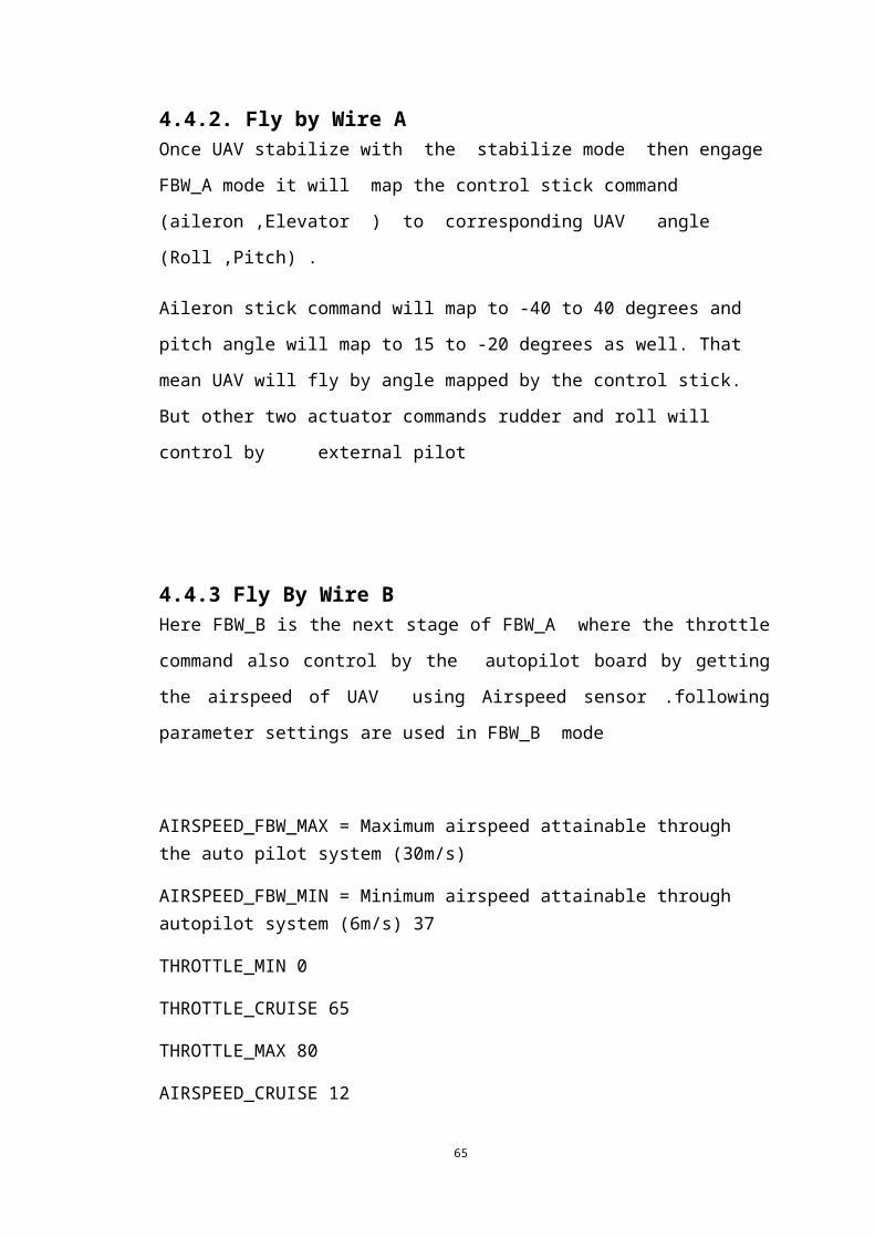
4.4.2. Fly by Wire A Once UAV stabilize with the stabilize mode then engage FBW_A mode it will map
the control stick command (aileron ,Elevator ) to corresponding UAV angle
(Roll ,Pitch) .
Aileron stick command will map to -40 to 40 degrees and pitch angle will map to 15
to -20 degrees as well. That mean UAV will fly by angle mapped by the control stick.
But other two actuator commands rudder and roll will control by external pilot
51
4.4.3 Fly By Wire B Here FBW_B is the next stage of FBW_A where the throttle command also control
by the autopilot board by getting the airspeed of UAV using Airspeed
sensor .following parameter settings are used in FBW_B mode
AIRSPEED_FBW_MAX = Maximum airspeed attainable through the auto pilot system (30m/s)
AIRSPEED_FBW_MIN = Minimum airspeed attainable through autopilot system (6m/s) 37
THROTTLE_MIN 0
THROTTLE_CRUISE 65
THROTTLE_MAX 80
AIRSPEED_CRUISE 12
(Parameter tested with RAVAN on 07th /03/2014)
4.4.4 Auto mode Roll, pitch, yaw and finally the airspeed will be controlled by the auto pilot system
based on the GPS waypoints, IMU data, current airspeed given by airspeed sensor and
also barometric pressure sensor. Here course is calculated using waypoint GPS
coordinates. Therefore hold_course parameter is set to -1 to reset it every time. Crash
checker is included. Here if airplane shows a pitch greater than 45° crash timer goes
to 255 and navigation pitch will go to zero. Then if pitch goes less than 45° timer will
decrement.
52
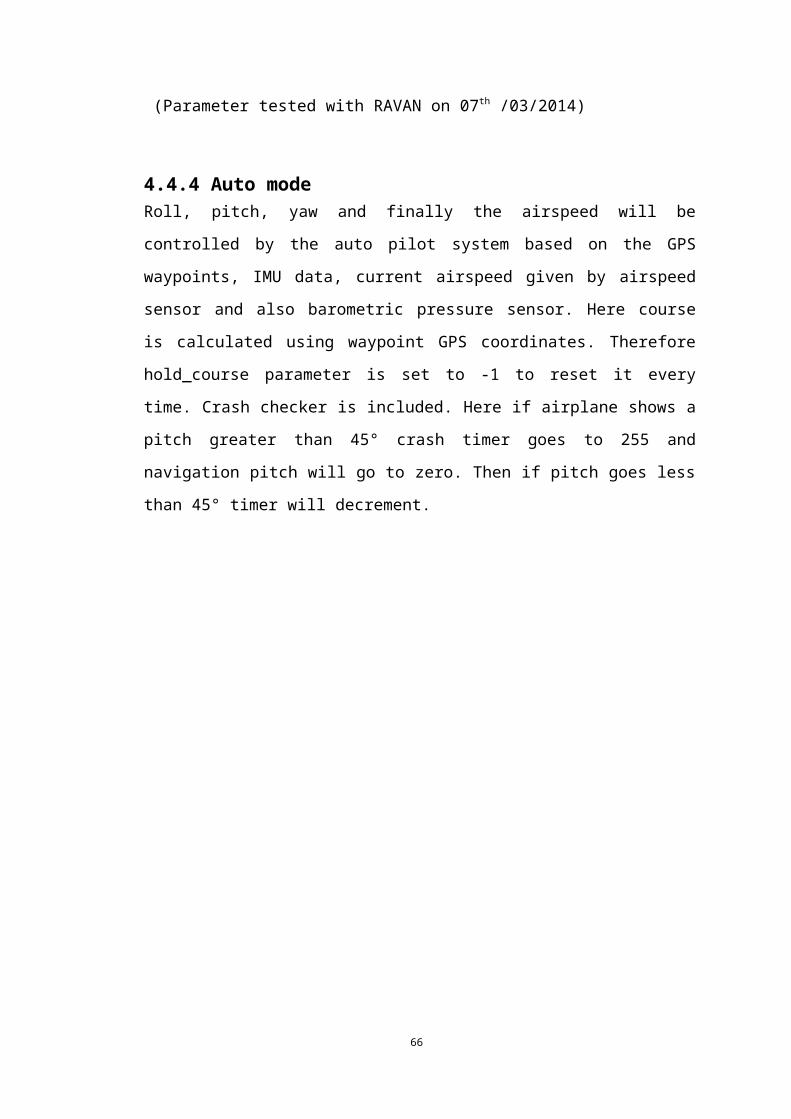
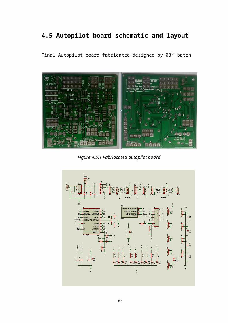
4.5 Autopilot board schematic and layout
Final Autopilot board fabricated designed by 08th batch
Figure 4.5.1 Fabriacated autopilot board
Figure 4.5.2 Schematic of Autopilot system
53
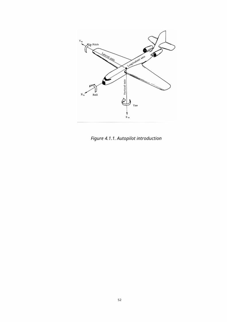
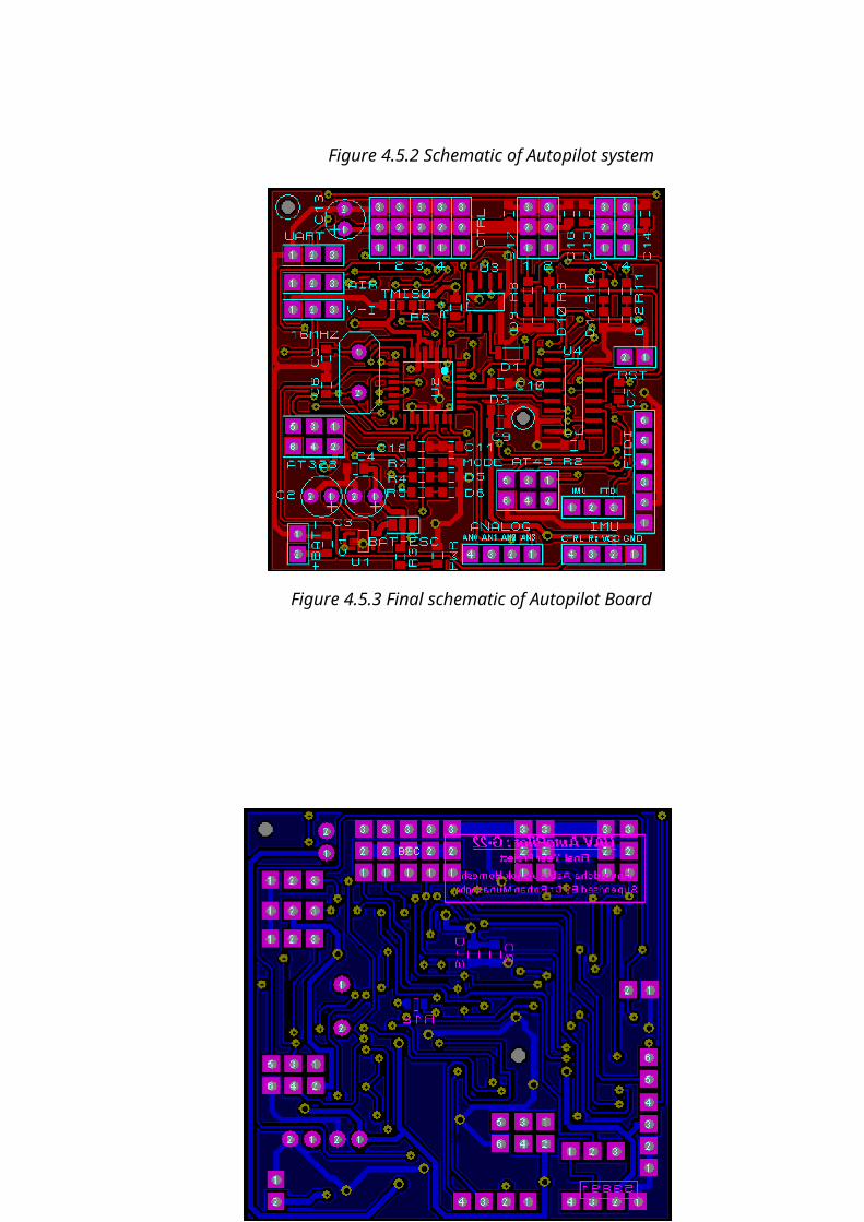
Figure 4.5.3 Final schematic of Autopilot Board
54
Figure 4.5.6 bottom layer of Autopilot board
55

4.6 Sensors used in Autopilot System
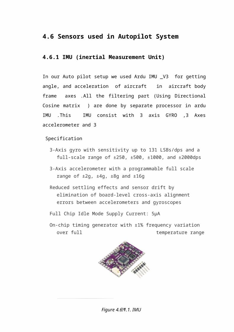
4.6.1 IMU (inertial Measurement Unit)
In our Auto pilot setup we used Ardu IMU _V3 for getting angle, and acceleration
of aircraft in aircraft body frame axes .All the filtering part (Using Directional
Cosine matrix ) are done by separate processor in ardu IMU .This IMU consist with
3 axis GYRO ,3 Axes accelerometer and 3
Specification
3-Axis gyro with sensitivity up to 131 LSBs/dps and a full-scale range of ±250, ±500, ±1000, and ±2000dps
3-Axis accelerometer with a programmable full scale range of ±2g, ±4g, ±8g and ±16g
Reduced settling effects and sensor drift by elimination of board-level cross-axis alignment errors between accelerometers and gyroscopes
Full Chip Idle Mode Supply Current: 5µA
On-chip timing generator with ±1% frequency variation over full temperature range
Figure 4.6.1.1. IMU
56
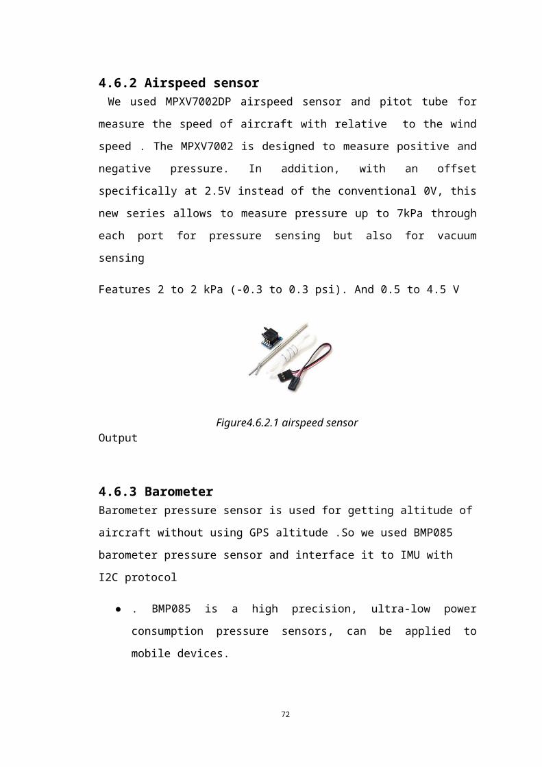
4.6.2 Airspeed sensor We used MPXV7002DP airspeed sensor and pitot tube for measure the speed of
aircraft with relative to the wind speed . The MPXV7002 is designed to measure
positive and negative pressure. In addition, with an offset specifically at 2.5V instead
of the conventional 0V, this new series allows to measure pressure up to 7kPa through
each port for pressure sensing but also for vacuum sensing
Features 2 to 2 kPa (-0.3 to 0.3 psi). And 0.5 to 4.5 V Output
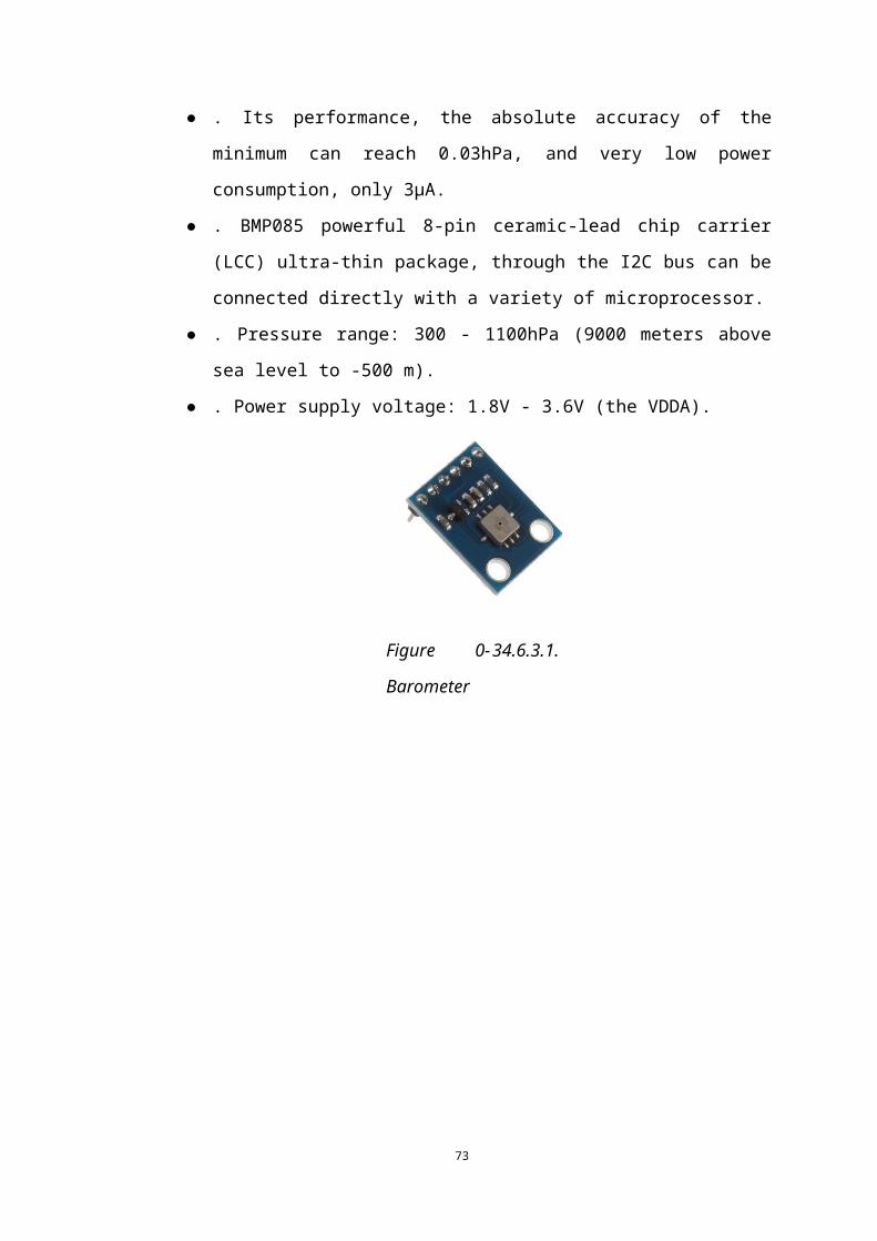
4.6.3 Barometer Barometer pressure sensor is used for getting altitude of aircraft without using GPS
altitude .So we used BMP085 barometer pressure sensor and interface it to IMU with
I2C protocol
● . BMP085 is a high precision, ultra-low power consumption pressure sensors,
can be applied to mobile devices.
● . Its performance, the absolute accuracy of the minimum can reach 0.03hPa,
and very low power consumption, only 3μA.
● . BMP085 powerful 8-pin ceramic-lead chip carrier (LCC) ultra-thin package,
through the I2C bus can be connected directly with a variety of
microprocessor.
● . Pressure range: 300 - 1100hPa (9000 meters above sea level to -500 m).
● . Power supply voltage: 1.8V - 3.6V (the VDDA).
Figure4.6.2.1 airspeed sensor
Figure 0-34.6.3.1.
57
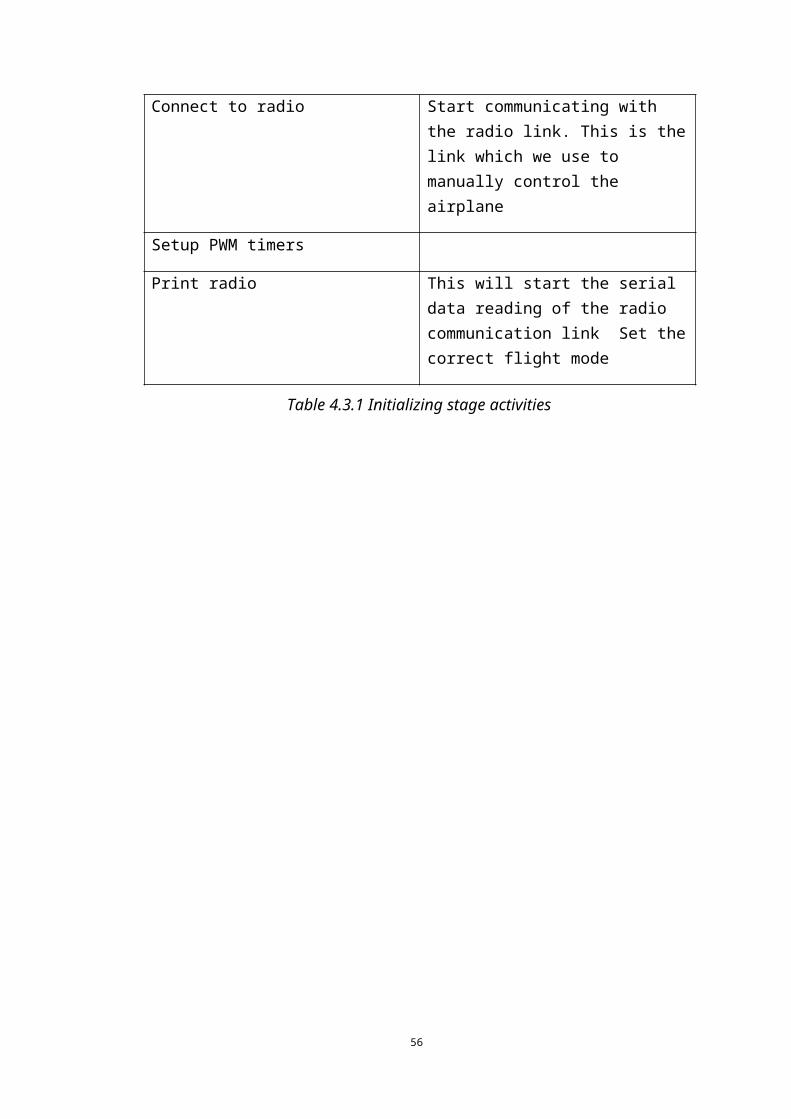
Figure 0-34.6.3.1.
58
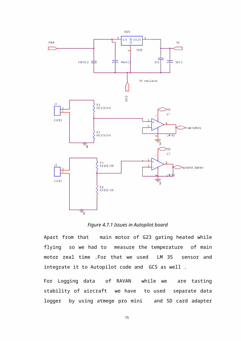
4.7 Autopilot board issues and overcomes Once we increase the main motor power the power line interferences get high
therefore we have to isolate every power supply and provide sufficient power to
autopilot board with externally with separate battery
So we upgrade power regulated IC mic5205 to 7805 power regulated IC and added
more voltage protection to that power supply
As we using separate power supplies to power autopilot board, VPN based telemetry
system, and main power battery for power the motor we have to measure the voltage
of
59
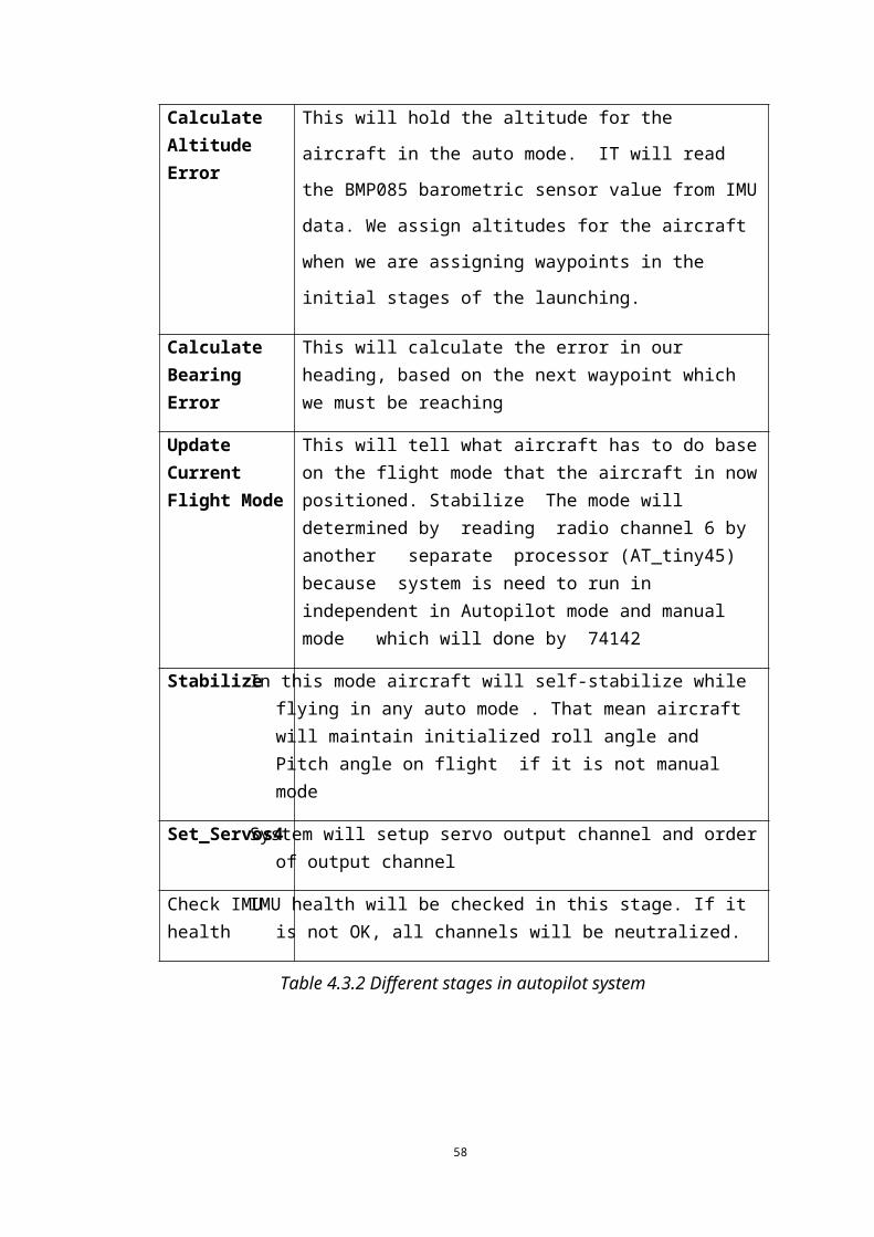
Figure 4.7.1 Issues in Autopilot board
Apart from that main motor of G23 gating heated while flying so we had to
measure the temperature of main motor real time .For that we used LM 35 sensor
and integrate it to Autopilot code and GCS as well .
For Logging data of RAVAN while we are tasting stability of aircraft we have to
used separate data logger by using atmege pro mini and SD card adapter for
getting IMU data , airspeed Data we used Arduino Uno board as well.
60

5. Live Video and Telemetry
5.1 Introduction to problem addressedA major expectation of this project was to implement a live video stream to be received on
the ground station. The following methods were considered for this task.
1. A radio link with transmitter on UAV and receiver on the ground station
2. An IP based video stream to be received over the 3G network
A radio link is capable of providing a high bandwidth video downstream without relying on
the 3G network. However it has many limitations. The most influential limitation in this
specific application is the fact that the distance which can be covered from this link is limited
to line-of-sight of radio link. The cost of the transmitting equipment is considerably high and
using the radio frequency required for this application requires permission from relevant
authorities.
However using the WCDMA network has many advantages over the above mentioned
approach. Most importantly, line-of-sight limitations do not apply in this approach, and the
UAV can maintain a video downstream wherever the WCDMA network is available. This
approach is much cheaper than the above mentioned approach since WCDMA based
equipment are commonly available.
Hence it was decided to implement the video link using WCDMA. However a separate radio
link is recommended in short distance applications requiring higher image quality and update
frequency.
61
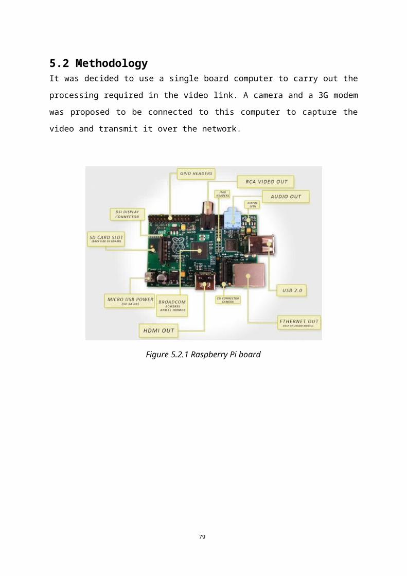
5.2 MethodologyIt was decided to use a single board computer to carry out the processing required in the
video link. A camera and a 3G modem was proposed to be connected to this computer to
capture the video and transmit it over the network.
Figure 5.2.1 Raspberry Pi board
62
Figure 5.2.2 Pandaboard
63
5.3 Selecting a Single-board computer
Raspberry Pi, Pandaboard and Beagle board were considered to be used as the single-board computer.
5.3.1 RapsberryPi
700 MHz Low Power ARM1176JZ-F Applications Processor
512MB SDRAM
Composite RCA (PAL and NTSC), HDMI (rev 1.3 & 1.4). resolutions from 640×350
to 1920×1200
Raw LCD Panels via DSI
HDMI audio out
Dual USB Connector
USB and DC power
5.3.2 PandaBoard
Dual-core ARM Cortex A9 MPCore processor manufactured by Texas Instruments,
running at 1GHz
1 GB RAM
DVI-D monitor connector
LCD expansion header
Audio in and out
One USB on-the-go port and two standard USB ports
WiFi and Bluetooth connectivity
USB and DC power
No RCA connector
5.3.3 BeagleBoard
Cortex A8-based processor by Texas Instruments, running at 720 MHz
128 MB RAM
64

DVI-D monitor connector
S-video connector for NTSC or PAL television or wearable visor
Stereo audio in and out
One USB port
USB and DC power
No RCA or HDMI connector
It was decided to use Raspberry Pi since it matched the size considerations, power
requirements and featured extensive community support which we decided was essential in
our set up. The Raspberry Pi organization has also developed a 5MP camera which we
decided to test later for our application.
65
5.4 Raspberry Pi single board computerRaspberry Pi is a single board computer which runs a Debian based linux os in default.
5.4.1 Configuring a webcam to work with Raspberry Pi
In order to provide a proof of concept of implementing a live video link using Raspberry Pi, it
was decided to test the basic configuration using a webcam and 3G modem.
A generic webcam was connected to one USB port and a E220 internet dongle was connected
to the other USB port.
5.4.1.1 Testing the webcamThe following command was issued on terminal to test whether the webcam is properly
connected and working.
$ sudo camorama
If the webcam is properly working the above command displays the view from the camera.
5.4.1.2 Testing the e220 Internet dongleWvdial was installed as the dialer using the following command
$ sudo apt-get install wvdial
Wvdial is a point-to-point protocol dialer which dials a modem and starts pppd in order to
connect to the Internet.
The configuration file for the internet device is located at /etc/wvdial.conf
In order to open this file for editing,
$ sudo nano /etc/wvdial.conf
It is required to edit this file according to the settings of service provider. The following
settings should be updated
66
[Dialer Defaults]Modem = /dev/ttyUSB0Baud = 1843200Modem Type = Analog ModemInit2 = ATZInit3 = ATQ0 V1 E1 S0=0 &C1 &D2 +FCLASS=0Init4 = AT+CGDCONT=1,"IP","m3static"Dial Command = ATDTPhone = *99***1#Username = fooPassword = barStupid Mode = yes
After the configuration file is updated and saved, we tested the Internet connectivity using
$ sudo wvdial play &
67
5.4.2 Uploading video to InternetThere are a number of Internet video broadcasters which let uploaders to submit their live
video streams. Ustream, Youtube and Justin.tv are popular examples. In our test, we used
Justin.tv. Upon registration, Justn.tv provides us with an upload URL with port number.
avconv[http://libav.org/avconv.html] was installed on Raspberry Pi as the streaming software.
It is a very fast video converter which can convert between arbitrary sample rates. Avconv
can read input from and write the output to files, network stream and pipes.
The below command takes the video from the USB camera as input, convert it to h264 format
and uploads it to justin.tv
>> $ avconv -f video4linux2 -s 640×360 -r 10 -b 350k -i /dev/video0 -f flv rtmp://live.justin.tv/UAV_smp
The switches used in the above command has the following functionality.
Switch Function
-f video4linux2 This command is used to direct the OS recognized video device as the input for the command. In this case the USB webcam is attributed as the video ‘file’
-s Stream specifie. Sets frame size. In this case 640*320
-r Sets frame rate. In this case 10 frames per second
-b Bitrate. 350k.
Table 5.4.2.1 Switches used in avconv
68
5.4.3 Results of this test
The overall result of this test was not satisfactory. There was a considerable delay in the
received video stream. The quality of image frames were very low. Update frequency was
also low. The following reasons were identified as the major reasons for these issues.
1. Not providing separate power to USB camera and internet device.
2. Delay in reaching the third party upload service over the Internet
3. Lower quality of the USB camera used
In order to solve these issues it was decided to;
1. Use a separate power supply for the external USB devices.
2. Host the server locally and implement the client server system using a separate VPN
3. Use a 5MP camera specifically designed for the Raspberry Pi
69
5.5 Power supplyWhen using external USB peripherals with Raspberry Pi, it is not recommended to let these
peripherals run from the main power of the board. This results in a higher current passing
through the board which might result in damaging it. As a solution, an external powering
method was designed which provided power from battery to USB devices separately.
5.6 VPN implementation
A point to point network was created using two SIMs provided by Mobitel for research
purposes. It enabled us to implement the required client server video streaming method
between the ground station and UAV.
It is required to use a different Access Point Name (‘m3static’) in this configuration and the
following static IP addresses were obtained.
10.103.0.33
10.103.0.34
5.7 Raspberry Camera
This is a 5 mega pixel camera which can be connected to the Raspberry Pi using the camera serial interface.
70
Figure 5.7.1 Raspberry Camera
5.7.1Testing the cameraIt is required to enable the camera on Raspberry Pi. This should be done by enabling the
camera on raspi-config
>> $ sudo raspi-config
The below command gives a preview of the camera view.
>> $raspivid -d
5.8 Implementing video link using the point to point networkThere are two methods to implement this architecture.
1. Setting Raspberry Pi as the video server and accessing it from GCS which works as
the client
2. Setting the GCS side as server and configuring Pi to write the video stream on a
listening port of the server
5.8.1. Pi as server and GCS as client
VLC player was installed on Raspberry Pi and it works as a video server. In order to start the
server the point to point network was connected using wvdial and the following command
71
was typed on terminal.
>> $raspivid -o - -t 9999999 |cvlc -vvv stream:///dev/stdin --sout '#rtp{sdp=rtsp://:8554/}' :demux=h264
The above command initializes a video server at the static IP address assigned to the
Raspberry Pi on port 8554. The switches used in the above command has following
functionality.
Switch Functionality
-o Output location. Here the output is piped to cvlc
-t Timeout/Shutdown. Set this to a very high value
-vvv stream:///dev/stdin
Starts VLC in terminal with input of type stream and location stdin, which is the standard input.
-sout ‘#rtp{sdp=rtsp://:8554/}’
sout sends the current stream to given address. In this case it is sent to port 8554 on Realtime Streaming Protocol. Any computer on this network can view this stream by accessing port 8554 on this machine’s IP address.RTP - stream over Realtime Transport Protocol.
demux=h264 h264 is one of the most common video formats used in recording, compression and distribution of video.
Table 5.8.1.1 Switches used in raspivid command
In order to view the video stream from Ground Station, it was first connected to the point to
point network. After that, VLC player was started and on File → Open Network Stream, the
following parameters was given.
72

Figure 5.8.1.1 image of open network stream dialog with relevant settings
VLC starts to play the live video once the ‘open’ button is pressed.
5.8.2. GCS as server and Pi as client
In this configuration, a server was created on ground station side and Raspberry Pi was set up to access it and write the relevant video stream to the listening port.
1. Netcat was installed on Raspberry Pi
Netcat is a computer networking tool used to communicate between computers using TCP or
UDP. It’s ability to work as a back-end driven by other programs and scripts is the main
advantage. Netcat is widely used for port scanning, port listening and file transfers.
73
2. On ground station Netcat and Mplayer was downloaded and copied to a folder. (eg: D:/UAV)
Mplayer is an open source media player available on many operating systems. It can take an
input stream and transcode it into a specific output format applying various transforms. It can
be provided with an input stream and called from the command line.
3. Following command was issued on ground station’s command prompt
>>nc -L -p 5001 | mplayer -fps 15 -cache 512 -
This command starts listening on port 5001 using Netcat. When data is received on that port,
it pipes this data to mplayer as a video stream.
The switches used in the above command has following functionalities
Switch Functionality
-L Listen harder. Starts to listen again when the client connects after a disconnection. Very useful in this application because network disconnection is a possibility when the UAV is flying in higher altitudes and other low signal reception areas.
-p Specifies which port to listen to. In this case 5001
-fps Number of frames per second. A higher FPS provides a smooth picture but requires more bandwidth. 15 in this case.
-cache Specifies how much memory to use when precaching a file/stream object. 512 kilobytes in this case.
Table 5.8.2.1 Switches used in Netcat
4. Following command was issued on Raspberry Pi terminal
>> raspivid -w 640 -h 480 -fps 15 -n -t 999999 -o - | nc 10.103.0.33 5001
This command captures the video from camera using raspivid and pipes it to netcat which
74
writes this stream on port 5001 of 10.103.0.33 , which is the Ground Station. Switches used
in this command have following meaning.
Switch Functionality
-w Sets image width of the video. 640 pixels in this case.
-h Sets image height of the video. 480 pixels in this case.
-fps Number of frames per second. 15 here.
-n No preview. Prevents raspivid from showing a preview locally. Very important since this saves memory and processing.
-t Time before shutdown. This is set to a very high value to receive the video during complete mission duration.
Table 5.8.2.2 Switches used in raspivid
5.8.3 Comparison between the two methods mentioned above
In the first method VLC player was executed on Raspberry Pi. This task was processor
intensive and resulted in requiring a higher current from the battery. Sometimes this resulted
in power downs. However, the second approach was less processor intensive on the
Raspberry Pi side and did not resulted in power downs. Hence it was decided to proceed with
the second approach where the ground station is set as the server.
75
5.9 Selecting the most suitable video codec
Testing the live video quality under this configuration
The video link was tested in this configuration under different resolutions, cache amounts and
the delay was measured in each case.
Frame Height (pixel)
Frame Width (pixel)
Frame Rate
(fps)
Cache (kB) Delay (s)
240 320 15 1000 14
240 320 30 1000 21
480 640 15 1000 23
Table 5.9.1 Video delay with different settings
Since it was noticed that a considerable delay was present in even under the lowest
resolution, it was decided to check whether there is an issue with the video link.
The following reasons were identified as possible reasons for the delay
1. Uplink speed limit in the provided point to point network
2. Limited uplink speed of the Internet device used
The first issue was solved by contacting Mobitel to remove the speed caps on the connection.
The limited uplink speed of the Internet dongle(384 kbps) was identified as a major reason for the delay. It was decided to use an Internet device with a higher uplink speed.
5.10 Configuring ZTE 4G router on Raspberry Pi
76
1. Manually up the ethernet interface using the following command
>> $ sudo ifup eth1
2. On Midori (browser) go to http://m.home and press connect
Note: initially set APN to ‘m3staic’
Test results after these modifications
Height Width Cache Delay
240 320 1000 6
240 320 1000 15
480 640 1000 17
Table 5.9.2. Video results after modifications
77
5.10 ConclusionAlthough the WCDMA based video link has many advantages as discussed earlier[where??] ,
the following disadvantages were recognized after several flight tests.
The video link is not reliable in mission critical applications. This was very evident when the
UAV was flying in higher altitudes at higher speeds. Since the mobile network is targeted to
serve the customers in ground level, the signal level received by the UAV in higher altitudes
is considerably low.
The WCDMA point to point connection was analyzed by the service provider during a flight
test. It was reported that the connection experiences interrupts because in the high altitude the
3G module in the UAV ‘sees’ many antennas and rapidly transform between them. A
disconnection was observed when the UAV exceeded the altitude of 250m.
It can also be argued that the compression mechanism used in the video encoders is not very
efficient in this application because the frames are changing rapidly. In MPEG4, the
difference vector between consecutive frames is transmitted. In cases where the frames do not
change rapidly(for example, an online video chat where a large area of the video frames do
not change at all) this compression works very efficiently. However in the case of
broadcasting the image seen by the camera mounted on the UAV, this compression is not
very efficient as the frames change rapidly and there’s considerable difference between
successive frames.
It is recommended to use a radio based video link in mission critical applications with the
WCDMA video link as a backup when line of sight link is not available.
78
5.11 Implementing telemetry over the point to point network
It was decided to implement a telemetry data downlink from UAV to ground station, and
control data uplink from ground station to UAV, using the same point to point network. An
IP based telemetry and control link has the following advantages over a traditional radio
based link.
1. The communication link is available in long distant operations whereas the radio link is available in only a few km radius
2. Specialized radio transmitting equipment and procedure require permission. In the IP based approach we can utilize the existing WCDMA network.
3. This method is much cheaper than a radio link
A client server based software was implemented on Raspberry Pi and ground station to carry
out this task. The Raspberry Pi was connected to the autopilot board using serial
communication on general purpose input output(GPIO) pins.
1. Connecting Raspberry Pi to the Autopilot board
Raspberry Pi’s GPIO pins work in 3V and the autopilot board works in 5V. A voltage
converter is required to interface these two boards.
2. Setting up server on ground station
%%
Import subprocessimport signalimport serialimport socketimport timeimport osimport os.pathimport thread
79
import sys
#ip_vpn = '10.103.0.33'#ip_local = '169.254.66.18'
## definesip = '10.103.0.33'
serial_baud = 38400serial_port = 8085
vid_w = 640vid_h = 480vid_fps = 15vid_port = 5001
threadAllowFilePath = '/home/pi/Desktop/run_thread'
## global variablestele_start = 0
## Threadsdef connect_thread(): try: os.system('sudo ifup eth1') except: print 'connect thread failed (connect_thread)!!!', sys.exc_info()[0]
def video_thread(): print '<Thread> video @ ' + `vid_w` + 'x' + `vid_h` + ' ' + `vid_fps` + 'fps port:' + `vid_port` try: os.system('raspivid -w ' + `vid_w` + ' -h ' + `vid_h` + ' -fps ' + `vid_fps` + ' -n -t 999999 -o - |nc ' + `ip`+' ' + `vid_port`) except: print 'video thread failed (video_thread)!!!', sys.exc_info()[0]
def telemetry_thread(): global tele_start print '<Thread> telemetry @ ' + `serial_baud`+ ' : ' + `serial_port` try: sp = serial.Serial('/dev/ttyAMA0', serial_baud, timeout=30) sp.open() server = socket.socket()
80
server.connect((ip,serial_port)) try: while 1: response = sp.readline() server.send(response) except KeyboardInterrupt: sp.close() except: tele_start = 0 print 'telemetry thread failed (telemetry_thread)!!!', sys.exc_info()[0]
##
def isOnline(): print '.', try: p = subprocess.Popen('ping ' + `ip` + ' -c 1', shell = True, stdout=subprocess.PIPE) out,err = p.communicate() if ('exceed' in out): return False else: return True except: print 'online check failed (isOnline)!!!', sys.exc_info()[0]
def try_video(): try: p = subprocess.Popen('ps -A|grep raspivid', shell = True, stdout=subprocess.PIPE) out, err = p.communicate() if len(out.splitlines()) == 0: thread.start_new_thread(video_thread,()) except: print 'video thread detection failed (try_video)!!!', sys.exc_info()[0]
def try_telemetry(): global tele_start try: if tele_start == 0: tele_start = 1 thread.start_new_thread(telemetry_thread,()) except: print 'telemetry thread detection failed (try_telemetry)!!!', sys.exc_info()[0]
def kill_all():
81
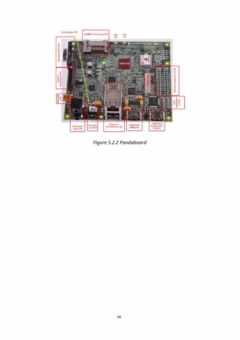
try: p = subprocess.Popen('ps -A|grep raspivid', shell = True, stdout=subprocess.PIPE) out, err = p.communicate() lines=out.splitlines() print 'killing ' + `len(out.splitlines())` + ' process(es)' for x in range(0,len(lines)): words = lines[x].split() print '\t' + words[3] pid = words[0] os.system('sudo kill ' + pid) except: print 'kill failed (kill_all)!!!', sys.exc_info()[0]
def threadAllowed(): try: return os.path.isfile(threadAllowFilePath) except IOError: print 'threadAllow check failed!',sys.exc_info()[0] return False
def main(): try: print "Start" kill_all() #return() print '<Thread> enable router' thread.start_new_thread(connect_thread,()) print 'Connecting to ' + `ip` + '...' while isOnline() == False: continue print '\nConnected to ' + `ip` + '!' try_video() time.sleep(0.5) try_telemetry() time.sleep(2) prev_time = 0 print 'Main loop started..' while threadAllowed(): now_time = int(round(time.time() * 1000)) if now_time - prev_time > 2:
82
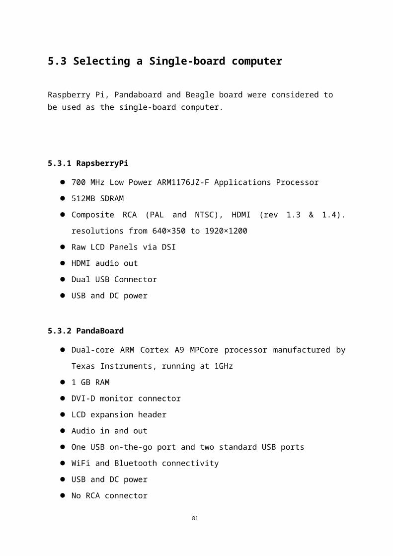
try_video() try_telemetry() prev_time = now_time print 'Thread not allowed. Script end!' except: print 'main function failed (main)!!!', sys.exc_info()[0]
if __name__=="__main__": main()
%%
import socket
serversocket = socket.socket(socket.AF_INET, socket.SOCK_STREAM)
host = socket.gethostname()
port = 8085
print (host)
print (port)
serversocket.setsockopt(socket.SOL_SOCKET, socket.SO_REUSEADDR, 1)
serversocket.bind((host, port))
serversocket.listen(5)
print ('server is listening')
(clientsocket, address) = serversocket.accept()
print ("connection found!")
while 1:
data = clientsocket.recv(1024)
print (data)
83
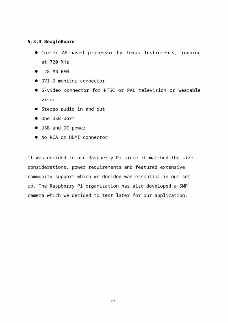
The above code starts a listener on Ground Station on port 8085. From Raspberry pi this can be addressed from 10.103.0.34:8085
3. Setting up client on Raspberry Pi
import socket
s = socket.socket()
host = “10.103.0.34"
port = 8085
s.connect((host,port))
s.send('randomData')
data = ''
data = s.recv(1024)
print (data)
s.close
84
6. Discussion and Conclusion
UAV technology, although being a well-developed field in first world countries is in a
primary state in Sri Lanka. The principle reason for this is inability to afford the cost
associated with acquiring air crafts, auto pilot systems and expert knowledge. In our project
we tried to build a platform which can be used to demonstrate the ability to build a UAV
locally with comparably minimal costs. Implementing live video and telemetry successfully
demonstrated the UAVs ability to be used in real world applications and its success as a
research platform for future projects.
A principal contribution we did in this project was to practically ensure the reliability of
HSPA network to transfer control data in an automatic or manual flight mission. Developing
a stable UAV with more than thirty minutes flying time is a considerable achievement in this
project. It will also help future projects in the department since the work overhead to
physically build the UAV will be considerable minimized for future projects as we have
already built a working model along with necessary molds and design diagrams.
As future suggestions we wish to point out that the reliability of HSPA network for live
streaming at a given height at a given speed should be further investigated. Apart from that
automating the PID tuning procedure is another area further developments for this project can
be made.
85
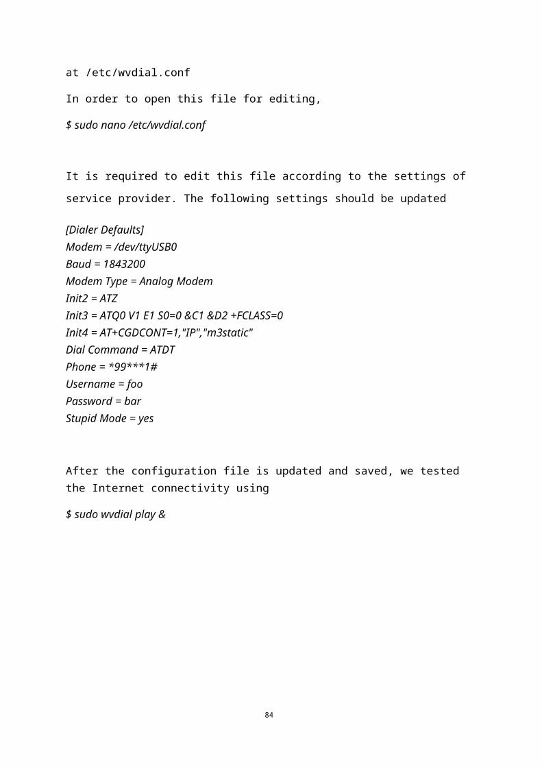
7. References
[1] Ardupilot Mega Web Site (code.google.com/p/ardupilot-mega/)
[2] Raspberry Pi home page(www.raspberrypi.org)
[3] QGroundControl home page(www.qgroundcontrol.org)
[4] Beagleboard home page(www.beagleboard.org)
[5] Arduino home page(www.arduino.cc)
86