fixed mount scanner fuzzyscan family quick start guide · fuzzyscan family quick start guide fixed...
TRANSCRIPT

FUZZYSCAN FAMILYQuick Start Guide
FIX
ED
MO
UN
T S
CA
NN
ER
Fixed Mount Scanner
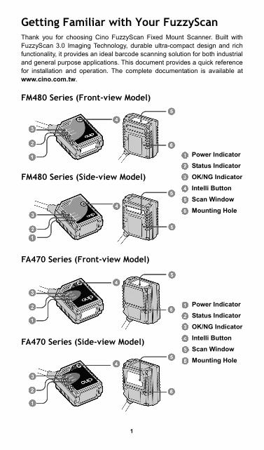
Getting Familiar with Your FuzzyScan Thank you for choosing Cino FuzzyScan Fixed Mount Scanner. Built with FuzzyScan 3.0 Imaging Technology, durable ultra-compact design and rich functionality, it provides an ideal barcode scanning solution for both industrial and general purpose applications. This document provides a quick reference for installation and operation. The complete documentation is available at www.cino.com.tw. FM480 Series (Front-view Model)
de-view Model)
FA470 Series (Front-view Model)
de-view Model)
Power IndicatorStatus IndicatorOK/NG IndicatorIntelli Button Scan Window Mounting Hole
Power IndicatorStatus IndicatorOK/NG IndicatorIntelli Button Scan Window Mounting Hole
FA470 Series (Si
FM480 Series (Si
1

2
Connect to Your Host Both standard RS232 and USB interfaces are available in different models. Each model is equipped with corresponding connector to meet various application demands. USB Models (FM4xx-11x/FA4xx-11x) The USB models provide a plug-and-play solution. Both USB HID and USB COM Port Emulation interfaces are available for user’s choice.
Pin No. Signal Description I/O TypeCase FG Frame Ground ---
1 VCC --- I 2 Data - USB Data - I/O 3 Data + USB Data + I/O 4 GND --- ---
RS232 Models (FM4xx-00x/FA4xx- 00x) The RS232 models support the standard RS232 interface equipped with a 9-pin D-sub connector with power jack for external 5VDC power inlet.
Pin No. Signal Description I/O TypeCase FG Frame Ground ---
1 --- --- --- 2 TXD Transmit Data O 3 RXD Receive Data I 4 --- --- --- 5 GND Signal Ground --- 6 --- --- --- 7 CTS Clear to Send I 8 RTS Request to Send O
9 VCC 5Vdc Power Supply I
Universal Models (FM4xx-98x/FA4xx-98x) The universal models support both standard RS232 and USB interfaces with OK/NG signal outputs and external trigger input.
Pin No. Signal Description I/O Type1 VCC 5Vdc Power Supply I 2 TXD Transmit Data O 3 RXD Receive Data I 4 GND Signal Ground --- 5 --- --- --- 6 RTS Request to Send O 7 OK OK Signal Output (3-24Vdc) O 8 Data + USB Data + I/O 9 Trigger External Trigger Input I
10 CTS Clear to Send I 11 --- --- --- 12 Data - USB Data - I/O 13 Shield Frame Ground --- 14 NG NG Signal Output (3-24Vdc) O
15 Reserved --- ---
4-pin Type A Connector
9-pin D-sub Female Connector
15-pin D-sub HD Female Connector

Install Your FuzzyScan Adjust Reading Angle The readability may be impacted by the specular reflection caused by the perpendicular reading angle. To get the most optimal reading performance, it is recommended to install the scanner at an approximate 15° angle to the perpendicular line of the target barcode. However, the reading angle and distance may vary depending on the size and printing quality of barcodes.
Mount Your FuzzyScan
There are two M3 mounting holes on the bottom of the chassis. Please follow below procedures to mount your scanner.
Prepare two appropriate M3 screws (minimal 4mm in depth) and decide your desired mounting location. Then adjust the two screws to accommodate 27mm center width.
Optimize the mounting position by adjusting reading angle and distance. Ensure the illumination envelop is not blocked by any external object.
Use the Intelli Button to verify the actual reading rate. If the reading rate is not good enough, please adjust the reading angle and distance to get the optimum readability.
Front-view Side-view
3
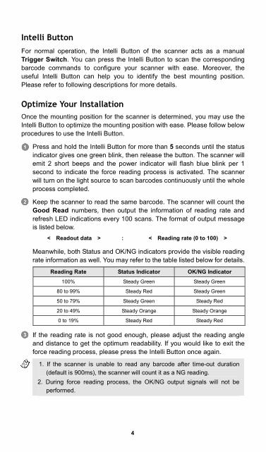
Intelli Button For normal operation, the Intelli Button of the scanner acts as a manual Trigger Switch. You can press the Intelli Button to scan the corresponding barcode commands to configure your scanner with ease. Moreover, the useful Intelli Button can help you to identify the best mounting position. Please refer to following descriptions for more details. Optimize Your Installation Once the mounting position for the scanner is determined, you may use the Intelli Button to optimize the mounting position with ease. Please follow below procedures to use the Intelli Button.
Press and hold the Intelli Button for more than 5 seconds until the status indicator gives one green blink, then release the button. The scanner will emit 2 short beeps and the power indicator will flash blue blink per 1 second to indicate the force reading process is activated. The scanner will turn on the light source to scan barcodes continuously until the whole process completed.
Keep the scanner to read the same barcode. The scanner will count the Good Read numbers, then output the information of reading rate and refresh LED indications every 100 scans. The format of output message is listed below.
< Readout data > : < Reading rate (0 to 100) >
Meanwhile, both Status and OK/NG indicators provide the visible reading rate information as well. You may refer to the table listed below for details.
Reading Rate Status Indicator OK/NG Indicator 100% Steady Green Steady Green
80 to 99% Steady Red Steady Green
50 to 79% Steady Green Steady Red
20 to 49% Steady Orange Steady Orange
0 to 19% Steady Red Steady Red
If the reading rate is not good enough, please adjust the reading angle and distance to get the optimum readability. If you would like to exit the force reading process, please press the Intelli Button once again.
1. If the scanner is unable to read any barcode after time-out duration (default is 900ms), the scanner will count it as a NG reading.
2. During force reading process, the OK/NG output signals will not be performed.
4

5
Use Your FuzzyScan Both FuzzyScan Barcode commands and Serial commands are available to configure your scanner. The FuzzyScan barcode commands are a series of proprietary barcodes which allow you to easily configure the scanner for most applications. Moreover, the FuzzyScan serial commands are ideal for precise and complicated reading control in machine-controllable environments. Please refer to the relevant documentations for details. External Trigger and Serial Trigger The scanner provides both external trigger and serial trigger to activate the scanning processes. Please note that the external trigger is only available for universal models. The serial trigger is workable for all models including RS232 serial and USB COM Port Emulation interfaces. User Defined Serial Trigger Command For user’s convenience to replace the other existing fixed mount scanner, the useful user defined serial trigger command allows you to trigger the scanner without impacting the existing application programs.
Scan Input Time-out The scan input time-out is an adjustable value for the time period that light source turns on. It’s available for presentation, alternative and level modes. The scanner keeps the light source on and continues to scan until the defined scan input time-out is up. You can adjust the time-out duration from 100 milliseconds to 99 seconds to meet various application demands. OK and NG Outputs The universal models support additional OK and NG outputs for more precise reading control. If the scanner got a good read, a signal will be outputted through the OK pin. However, if the scanner failed to read the barcode during a reading cycle or preset scan input time-out, a signal will be outputted through the NG pin. The OK and NG outputs are designed as NPN signal outputs and preset to active low. If necessary, you can change the active state of OK and NG outputs to meet your applications. Operation Modes The FuzzyScan Fixed Mount Scanner provides five different operation modes, including trigger, alternative, level, presentation and force modes to meet various application demands. Both the presentation and force modes support triggerless operation, you don’t need to use either external trigger or serial trigger to activate the scanning. But the trigger, alternative and level modes have to work with external trigger or serial trigger to scan barcode.
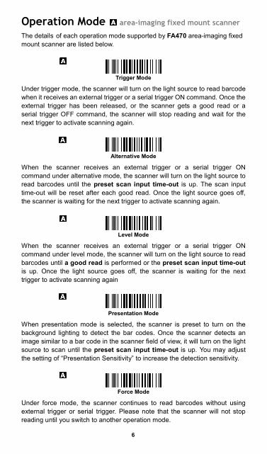
Operation Mode area-imaging fixed mount scanner
The details of each operation mode supported by FA470 area-imaging fixed mount scanner are listed below.
Trigger Mode
Under trigger mode, the scanner will turn on the light source to read barcode when it receives an external trigger or a serial trigger ON command. Once the external trigger has been released, or the scanner gets a good read or a serial trigger OFF command, the scanner will stop reading and wait for the next trigger to activate scanning again.
Alternative Mode
When the scanner receives an external trigger or a serial trigger ON command under alternative mode, the scanner will turn on the light source to read barcodes until the preset scan input time-out is up. The scan input time-out will be reset after each good read. Once the light source goes off, the scanner is waiting for the next trigger to activate scanning again.
Level Mode
When the scanner receives an external trigger or a serial trigger ON command under level mode, the scanner will turn on the light source to read barcodes until a good read is performed or the preset scan input time-out is up. Once the light source goes off, the scanner is waiting for the next trigger to activate scanning again
Presentation Mode
When presentation mode is selected, the scanner is preset to turn on the background lighting to detect the bar codes. Once the scanner detects an image similar to a bar code in the scanner field of view, it will turn on the light source to scan until the preset scan input time-out is up. You may adjust the setting of “Presentation Sensitivity” to increase the detection sensitivity.
Force Mode
Under force mode, the scanner continues to read barcodes without using external trigger or serial trigger. Please note that the scanner will not stop reading until you switch to another operation mode.
6

7
Operation Mode inear fixed mount scanner
The details of each operation mode supported by FM480 fixed mount scanner are listed below.
Trigger Mode
Under trigger mode, the scanner will turn on the light source to read barcode when it receives an external trigger or a serial trigger ON command. Once the external trigger has been released, or the scanner gets a good read or a serial trigger OFF command, the scanner will stop reading and wait for the next trigger to activate scanning again.
Alternative Mode
When the scanner receives an external trigger or a serial trigger ON command under alternative mode, the scanner will turn on the light source to read barcodes until the preset scan input time-out is up. The scan input time-out will be reset after each good read. Once the light source goes off, the scanner is waiting for the next trigger to activate scanning again.
Level Mode
When the scanner receives an external trigger or a serial trigger ON command under level mode, the scanner will turn on the light source to read barcodes until a good read is performed or the preset scan input time-out is up. Once the light source goes off, the scanner is waiting for the next trigger to activate scanning again.
resentation Mode
Under presentation mode, the scanner will automatically detect the object movement in the scanner field of view. Once the scanner detects an image similar to a barcode, it will turn on the light source to scan until the preset scan input time-out is up. For dark environments, you may adjust the setting of “Presentation Sensitivity” to increase the detection sensitivity.
Force Mode
Under force mode, the scanner continues to read barcodes without using external trigger or serial trigger. Please note that the scanner will not stop reading until you switch to another operation mode.
P
l
8
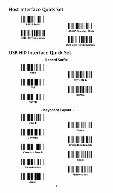
Host Interface Quick Set
USB HID Standard Mode
USB Com Port Emulation
USB HID Interface Quick Set - Record Suffix -
RETURN ◆
SPACE
ENTER
- Keyboard Layout -
France
United Kingdom-UK
Spain
Nertherlands
Japan
Latin America
Canadian French
Germany
USA ◆
TAB
None
USB HID Turbo Mode
RS232 Serial
9
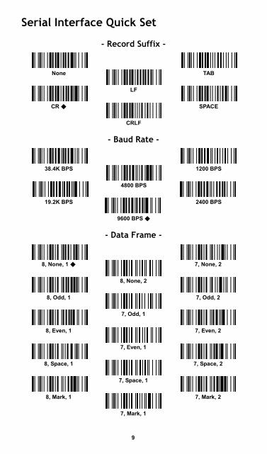
Serial Interface Quick Set
- Record Suffix -
TAB
LF
SPACE
CRLF
- Baud Rate -
1200 BPS
4800 BPS
2400 BPS
9600 BPS ◆
- Data Frame -
◆ 7, None, 2
8, None, 2
8, Odd, 1 7, Odd, 2
7, Odd, 1
7, Even, 2
7, Even, 1
7, Space, 2
7, Space, 1
7, Mark, 2
7, Mark, 1
19.2K BPS
8, None, 1
8, Even, 1
8, Space, 1
8, Mark, 1
38.4K BPS
CR ◆
None

10
USB HID Interface Control Command Parameter Selection Option Code
Keyboard Layout
USA ◆ France Germany United Kingdom-UK Canadian French Spain Sweden/Finland Portugal Norway
Latin America Italy Netherlands Denmark Belgium Switzerland-Germany Iceland Japan Universal
00 01 02 03 04 05 06 07 08
09 10 11 12 13 14 15 16 99
Record Suffix
None RETURN ◆ TAB SPACE
ENTER User define character
0 1 2 3
4 5
Preamble None ◆ 1-15 characters
FIN [00-7F], [FIN]
Postamble None ◆ 1-15 characters
FIN [00-7F], [FIN]
Intermessage Delay None ◆ 1-99 (x5) msec.
FIN (2 digits)
Intercharacter Delay None ◆ 1-99 (x5) msec.
FIN (2 digits)
Interfunction Delay None ◆ 1-99 (x5) msec.
FIN (2 digits)
Caps Lock Control “Caps Lock Off” State ◆ “Caps Lock On” State Auto Detect
0 1 2
Caps Lock Release Control “Caps Lock On, Caps Off’’ ◆ “Caps Lock On, Shift Off’’
0 1
Function Key Emulation Enable ASCII 00-31 as KB function code output ◆ Enable ASCII 00-31 as Ctrl-xx output
0 1
Key Pad Emulation Disable key pad emulation ◆ Enable numeric output as key pad output
0 1
Upper/Lower Case Normal case ◆ Inverse case Upper case Lower case
0 1 2 3

11
Serial Interface Control Command Parameter Selection Option Code
STX/ETX Control Disable STX/ETX transmission ◆ Enable STX/ETX transmission
0 1
Record Suffix None CR ◆ LF CRLF
TAB SPACE User define character
0 1 2 3
4 5 6
Preamble None ◆ 1-15 characters
FIN [00-7F], [FIN]
Postamble None ◆ 1-15 characters
FIN [00-7F], [FIN]
Handshaking Protocol None ◆ RTS/CTS ACK/ NAK Xon/Xoff
0 1 2 3
Intermessage Delay None ◆ 1-99 (x5) msec.
FIN (2 digits)
Intercharacter Delay None ◆ 1-99 (x5) msec.
FIN (2 digits)
Interfunction Delay None ◆ 1-99 (x5) msec.
FIN (2 digits)
Serial Response Time-out
None 200 msec. 500 msec. ◆ 800 msec. 1 sec. 2 sec
3 sec. 4 sec 5 sec. 8 sec. 10 sec. 15 sec.
0 1 2 3 4 5
6 7 8 9 A B
Message String Breakdown
USB HID interface output (DOS/V, USB HID)
Preamble Data Length Prefix ID Scanned Data Suffix ID Postamble Record Suffix
1-15 char. 2-4 digits 1 or 3 char. Variable 1 or 3 char. 1-15 char. 1 char.
Serial interface output (RS-232, USB COM Port Emulation)
STX Preamble Data Length Prefix ID Scanned Data Suffix ID Postamble ETX Record Suffix
1 char. 1-15 char. 2-4 digits 1 or 3 char. Variable 1 or 3 char. 1-15 char. 1 char. 1 char.

12
Operation Control Command Parameter Selection Option Code
Redundancy None Level 1 ◆ Level 2 Level 3 Level 4 Level 5
Scan Voting
0 1 2 3 4 5
Power On Indicator Disable (LED off) LED steady on ◆ LED flash
0 1 2
Buzzer Tone Control Buzzer tone – mute Buzzer tone – low Buzzer tone – medium ◆ Buzzer tone – high Buzzer tone – extremely high
Power–on beep ◆ No Power–on beep
0 1 2 3 4 5 6
Good Read Duration Short Medium ◆ Long Extremely long Extremely short
0 1 2 3 4
Presentation Sensitivity
Level 1 Level 2 Level 3 Level 4 Level 5 ◆ Level 6 Level 7
0 1 2 3 4 5 6
Scan Rate Control Dynamic ◆ Fixed
0 1
Hands Free Time-out Short ◆ Medium Long Extremely long Disable
0 1 2 3 4
Scan Input Time-out
100 msec. 200 msec. 300 msec. 400 msec. 500 msec. 600 msec. 700 msec. 800 msec. 900 msec. ◆ User define: 1-99 sec.
0 1 2 3 4 5 6 7 8
9, (2 digits)

13
Output Control Command Parameter Selection Option Code
Dollar Sign Output Dollar sign output as “ $ “ ◆ Dollar sign output as “¥“ Dollar sign output as “ € “ Dollar sign output as “ £ “ Dollar sign output as “¢ “
0 1 2 3 4
Good Read Delay None ◆ 200 msec. 500 msec. 1 sec. 1.5 sec. 2 sec. 3 sec.
0 1 2 3 4 5 6
Reread Delay Disable Immediate time out ◆ Short time out Medium time out Long time out Force verification
Double Scan Verification
0 1 2 3 4 5
OK/NG Signal Active States OK low/NG low ◆ OK low/NG high OK high/NG low OK high/NG high
0 1 2 3
OK/NG Signal Output Control Disable OK/NG output Enable NG output Enable OK output Enable OK/NG output ◆
0 1 2 3
OK/NG Signal Duration 10 msec. 20 msec. 30 msec. 40 msec. 50 msec. 60 msec. 70 msec. 80 msec. 90 msec. 100 msec. ◆ User define: 1-99 (x50) msec.
0 1 2 3 4 5 6 7 8 9
A, (2 digits)
OK/NG Beeping Control Disable OK and NG beep Enable OK and NG beep ◆ Enable OK beep and disable NG beep Enable NG beep and disable OK beep
0 1 2 3
Symbology ID Transmission Disable symbology ID transmission ◆ Enable prefix CINO symbology ID transmission Enable suffix CINO symbology ID transmission Enable prefix and suffix CINO symbology ID transmission Enable prefix AIM symbology ID transmission Enable suffix AIM symbology ID transmission Enable prefix and suffix AIM symbology ID transmission
0 1 2 3 4 5 6

System Commands
(E ode) Master Default
System Information
(E ) Save User Default
PowerTool Host Link
Factory Default User Default
Option Codes
8
4
C
9
5
D
A
6
E
B
7 F
END (Exit)
FIN (Finish)
3
2
1
0
END xit Programming Mode
PROGRAM nter Programming M
14

P/N: YMAUB70010020R0
FuzzyScan Fixed Mount Scanner Quick Start GuideInternational Edition, Rev. B2
www.cino.com.tw
Regulatory
FCC part 15B
EN55022, EN55024,EN61000-3-2, EN61000-3-3
CNS13438
LED Eye Safety
Industry Canada ICES-003
IEC62471 Exempt group
V-3/2011.04, TECHNICAL REQUIREMENTS,Class B ITE
Clause 3, Article 58-2 of Radio Waves Act.
Cino makes no warranty of any kind with regard to this publication, including, but not limited to, the
implied warranty of merchantability and fitness for any particular purpose. Cino shall not be liable for
errors contained herein or for incidental consequential damages in connection with the furnishing,
performance, or use of this publication. This publication contains proprietary information that is protected
by copyright. All rights are reserved. No part of this publication may be photocopied, reproduced or
translated into any language, in any forms, in an electronic retrieval system or otherwise, without prior
written permission of Cino. All product information and specifications shown in this document may be
changed without prior notice.
Disclaimer
WarrantyCino warrants its products against defects in workmanship and materials from the date of shipment,
provided that the product is operated under normal and proper conditions. The warranty provisions and
durations are furnished by different warranty programs. The above warranty does not apply to any
product which has been (i) misused; (ii) damaged by accident or negligence; (iii) modified or altered by the
purchaser or other party; (iv) repaired or tampered by unauthorized representatives; (v) operated or stored
beyond the specified operational and environmental parameters; (vi) applied software, accessories or
parts are not supplied by Cino; (vii) damaged by circumstances out of Cino’s control, such as, but not
limited to, lightning or fluctuation in electrical power. Any defective product must follow the warranty
program and RMA procedures to return Cino for inspection.
© COPYRIGHT CINO GROUP • PC WORTH INT’L CO., LTD. ALL RIGHT RESERVED.