fixed fuel systems and permanently installed engines guide...fixed fuel systems and permanently...
TRANSCRIPT
2Fixed fuel systems and permanently installed engines
The Boat Safety Scheme Essential Guide
For more technical informationThe requirements in this chapter have been informed by, andmay refer to, the following technical references, codes andregulations. If you are building, fitting-out or making substantialchanges to a vessel, we strongly recommend you refer to, andtake account of, the codes and standards below:
n BS EN ISO 7840:2004 ‘Small craft. Fire-resistant fuel hoses’
n BS EN ISO 10088:2001 ‘Small craft. Permanently installedfuel systems and fixed fuel tanks’
n BS EN ISO 15584:2001 ‘Small craft. Inboard petrol engines.Engine-mounted fuel and electrical components’
n BS EN ISO 16147:2002 ‘Small craft. Inboard diesel engines.Engine-mounted fuel and electrical components’
n DIN 4798:1988 ‘Hosepipes for extra-light fuel oil; safetyrequirements, testing, marking’
n LP Gas Association Code of Practice 18 ‘Recommendationsfor the safe use of LPG as a propulsion fuel for boats,yachts and other craft’
n SAE J1527:2004 ‘Marine Fuel Hoses’
Fixed fuel systems and permanently installed enginesThe watertight nature of boats means that they also act as goodcontainers for leaks or overflows of flammable liquids and vapours!
Stored fuels such as diesel or petrol in confined and undrained spacescarry the risk of providing fuel for a fire or explosion. This chapter covers the need to keep fuel away from sources of ignition for as long as possible.
It also covers why the fuel filling and fuel supply arrangements must notallow leaks to accumulate inside the confines of your boat. Thus, all fuelsystem components must be in good condition. They must also be fireresistant, suitable for the fuel being used and kept away or shielded fromsources of heat.
To avoid pollution, spilt fuel oils are normally prevented from beingdischarged into the waterway and the detail of prevention is in Chapter 9.However, the overriding need to minimise the risk of fires, spread of fireand explosions, means that small amounts of overflowing fuel are betterdirected overboard than allowed to flow into the craft interior.
These requirements and checks apply to all boats with inboard enginesand to other fixed fuel systems supplying liquid-fuelled appliances suchas diesel heaters. Further requirements relating to appliances and theirinstallation and maintenance are in Chapter 8.
If you carry spare fuel in portable containers, the requirements related to the safe type and location of spare fuel containers is covered inChapter 5.
Boats obliged to meet BSS requirements must comply with the following:
1 All permanently installed fuel systems and fixed engines must bedesigned, installed and maintained in a way that minimises therisks of explosion, or of fire starting or spreading.
2 Fuel filling arrangements must prevent any overflow fromentering the interior of the vessel.
BSS Essential Guide
3 All fuel filling points must clearly identify the fuel in use.
4 Marking must be provided to identify the location of fuel systememergency shut-off devices, or their means of operation, whichare not in open view.
5 All permanently installed fuel systems must be designed,installed and maintained to ensure fuel-tight integrity.
6 All permanently installed fuel tanks and fuel system connectionsmust be accessible for inspection.
7 The pressure systems of steam-powered installations must have a current inspection certificate issued by a recognisedcompetent person.
An important prefaceon the nature of …
… petrolPetrol is very volatile, that is, it evaporates quickly generating highly flammable vapours. A small spill of petrol will create a largeamount of vapour. Likewise, when it is being transferred andespecially when a tank is being filled and the vapour in the ‘empty’tank is displaced by the liquid fuel. Even if the concentration ofvapour is too rich to burn immediately, it will dilute to flammable or explosive levels, even though given enough ventilation, it maydissipate to a safe level eventually.
Petrol vapour is three to four times heavier than air. It will sink to thelowest level of its surroundings, accumulating at low level in places suchas unventilated lockers and bilges or in enclosed spaces such as thecabins and cockpits of boats.
BSS Essential Guide 2nd Edition Aug 2005 Ch2/Pg3

…dieselAs with petrol, diesel as a liquid does not burn, but when it isheated, the vapour given off is combustible and will burn strongly.To reach this stage, termed the flash point, diesel fuel only needs tobe heated to around 56°C and this can be lower in winter due to theanti-waxing additives.
Diesel can be raised to flash point temperature by contact with gasflames, frictional sparks, electric sparks, and small fires as well as otherheat sources.
Diesel fuel will ignite readily; materials soaked through with diesel andacting as a wick, greatly assist the spread of an established fire. Oncealight, diesel burns with great heat and strength. [based on informationin the Library of Fire Safety, Vol. 2, Fire Protection Association,]
iInformationIf a small amount of fuel escapes overboard, through measuresdesigned to lower fire risks, it will be diluted naturally. If largequantities of fuel or other substances escape into a waterway youshould contact the Environment Agency/Scottish EnvironmentProtection Agency Pollution Hotline on 0800 80 70 60 (24hrs).
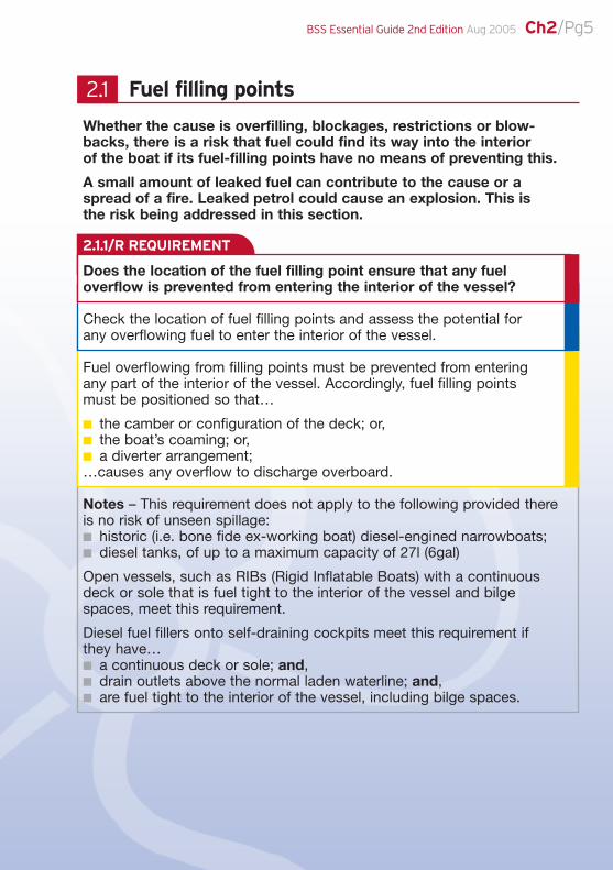
Sloped Deck High Coaming Diverter Arrangement
2.1.1/R REQUIREMENT
Fuel filling points
Whether the cause is overfilling, blockages, restrictions or blow-backs, there is a risk that fuel could find its way into the interior of the boat if its fuel-filling points have no means of preventing this.
A small amount of leaked fuel can contribute to the cause or aspread of a fire. Leaked petrol could cause an explosion. This is the risk being addressed in this section.
Does the location of the fuel filling point ensure that any fueloverflow is prevented from entering the interior of the vessel?
Check the location of fuel filling points and assess the potential for any overflowing fuel to enter the interior of the vessel.
Fuel overflowing from filling points must be prevented from entering any part of the interior of the vessel. Accordingly, fuel filling points must be positioned so that…
n the camber or configuration of the deck; or,n the boat’s coaming; or,n a diverter arrangement;…causes any overflow to discharge overboard.
Notes – This requirement does not apply to the following provided thereis no risk of unseen spillage:n historic (i.e. bone fide ex-working boat) diesel-engined narrowboats;n diesel tanks, of up to a maximum capacity of 27l (6gal)
Open vessels, such as RIBs (Rigid Inflatable Boats) with a continuousdeck or sole that is fuel tight to the interior of the vessel and bilgespaces, meet this requirement.
Diesel fuel fillers onto self-draining cockpits meet this requirement if they have…n a continuous deck or sole; and,n drain outlets above the normal laden waterline; and,n are fuel tight to the interior of the vessel, including bilge spaces.
2.1
BSS Essential Guide 2nd Edition Aug 2005 Ch2/Pg5

2.1.2/R REQUIREMENT
Preventing cross-contamination between different fuels, water andother liquids or spills into the hull is being addressed here. If fuel ispoured down the wrong deck connection, there is a risk of a fire,explosion, or a pollution incident. It may also be expensive andtime-consuming for the owner to remedy.
Is the fuel in use correctly and clearly marked on or adjacent to the fuel filling point?
Check for markings on or adjacent to fuel filling points.
The specific fuel type in use must be correctly and clearly marked on or adjacent to all fuel filling points:
n ‘DIESEL’; or ‘FUEL OIL’, or ‘GAS OIL’, or ‘DERV’, or ‘BIODESEL’; or,n ‘PETROL’, or ‘GASOLINE’; or;n ‘LPG BUTANE/PROPANE’ as appropriate; or,n ‘PARAFFIN’; or,n ‘PETROIL’.
Notes – The use of embossed tape (e.g. Dymo) or other lettering thatcan become illegible through cleaning or normal use is not acceptable.The marking must be legible with all lettering complete.
Marking fuel filling points solely with ‘fuel’ or ‘gas’ is not acceptable.
Marking fuel filling points with the internationally accepted symbol or thefuel in use is acceptable. The BSS Office can be contacted for guidanceas to a symbol’s compliance with the requirements.
bBest practiceWe recommend that other disused deck connections, if notblanked off, also be marked clearly to prevent cross-contamination and spillage.

iInformationDo not use metallic measuring tools on metallic petrol fillingpoints, they may cause sparks and ignite the petrol vapour.
2.1.3/R REQUIREMENT
2.1.4/R REQUIREMENT
Are all disused fuel filling points disabled?
Check all fuel filling points and other deck connections.
Identify any that are marked as fuel filling points, or that may be taken to be fuel filling points, but are no longer connected to a fuel tank.
Check for signs of disabling.
Unused fuel filling points must be permanently disabled to such an extent that it would require the use of tools to remove the disabling method.
Note – The use of a suitable proprietary adhesive to secure filling point caps or plugs in place etc. meets this requirement.
Having the right diameter line will help make sure that any fuel-filling nozzle is properly inserted and will help prevent ‘blow back’ of fuel when refuelling.
Is the internal diameter of the fuel filling point at least 31.5mm (11⁄4 in)?
Measure the internal diameter of each fuel filling point.
Fuel filling points must have a minimum internal diameter of 31.5mm (11⁄4 in).
Note – If it is not practicable to measure the internal diameter at fuelfilling points, an estimate based upon the external diameter of the fuel filling line can be made.
BSS Essential Guide 2nd Edition Aug 2005 Ch2/Pg7
bBest practiceInspect the connections routinely. Check the condition of hoseclamps that are used to make joints. Replace them on inspectionif they or the hose appear damaged, cracked, worn, or corroded.
We recommend the use of double clamps on a filling hose used for petrol.
We recommend that the fuel filling line is as short as practicable.
Supporting long lengths of hose at regular intervals may helpprevent abrasion damage against interior fittings and extend theuseful life of the hose.
2.2.1/R REQUIREMENT
Fuel filling lines
These lines need to be able to carry fuel effectively without any leaks, risks of leaks, overflows, or spills. With fuel filling lines that are located out of sight, leaks or material failure can go unnoticedunless regular checks are made.
Ineffective fuel connections will leak with the potential for causing fire and explosion or adding to the intensity of a fire and then it spreading.
Are the fuel-filling line connections leak free and in good condition,and are all fuel-filling hose connections accessible for inspection?
Check for the presence of fuel filling hose connections, and the condition by sight and touch.
Check the condition of fuel filling pipe connections where they can be seen or reached.
All fuel-filling hose connections must be accessible for inspection, andmust be secure and free of leaks, signs of damage and/or deterioration.
Fuel filling pipe connections must be secure and free of leaks, signs ofdamage and/or deterioration.
Note – If inaccessibility of any connection prevents it from being verified as leak free and in good condition, it will be considered as non-compliant until its good condition has been verified.
2.2

2.2.2/R REQUIREMENT
BSS Essential Guide 2nd Edition Aug 2005 Ch2/Pg9
2.2.3/R REQUIREMENT
Fuel must not be retained in the filling hose, as this could causeblow back when refuelling.
Is the fuel filling line self-draining so that fuel is not retained and is it free of kinks or other restrictions?
Check the fall of each fuel filling line.
Check for any kinks or other obvious restrictions in fuel filling lines where they can be seen or reached.
Fuel filling lines must be ‘self-draining’ i.e. fall continuously from thefilling point to the fuel tank connection so that fuel is not retained.
Fuel filling lines must not be kinked or restricted.
Note – Fuel filling lines must not have their internal bore diameterrestricted to less than 31.5mm (11⁄4 in).
Damaged or deteriorating fuel filling lines could fail and result in a leak that could form a potential fire, explosion, or pollutionhazard depending on the fuel used. In the case of petrol, hose notdesigned specifically for that fuel can fail rapidly. Indeed all fuel oilscan ‘attack’ unsuitable materials.
Is the material of the fuel filling line suitable and in good condition?
Check the material and condition of fuel filling lines, which can be seen or reached.
Check the markings on any fuel filling hose.
Fuel filling lines must not show signs of fuel leaks, damage, or deterioration.
Fuel filling hose must be marked as suitable for the fuel in use or supported by an appropriate declaration.
Notes – diesel filling hose in good condition may be accepted without marking or declaration provided it can be examined over its entire length.
Enough suitably marked diesel filling hose, or enough petrol hose,must be accessible to make a reasonable assessment as to the hose’s general condition.

2.3.2/R REQUIREMENT
bBest practiceWe recommend that you use hoses marked with BS EN ISO 7840although hoses marked with SAE J 1527, DIN 4798 or markedwith the type of fuel in use are acceptable.
2.3.1/R REQUIREMENT
Fuel tank vents
Potentially dangerous and polluting fuel blow-backs are known to happen during refilling. The tank also needs to be able to ‘breathe’ tohelp the supply of fuel to the engine or appliance. Temperature changescause the volume of fuel to expand and contract.
Venting needs to be effective at all levels of fuel in the tank. A vent linecan also be a filling line, or an overflow line, and the requirement for avent does not apply to small auxiliary tanks with a vented filling cap onthe tank.
Does every fuel tank have an effective vent facility?
Check all fuel tanks for the provision of a vent facility.
A vent line must be fitted to the top of each fuel tank, or a vent must befitted to either the filling cap, or filling line.
Note – Vents in the filling cap or filling line must have their outlet at or above filling point level.
Does the fuel tank vent line have a minimum internal diameter of 9.5mm?
Measure the outside diameter of fuel vent lines.
The internal diameter of vent lines must be at least 9.5mm (3⁄8 in).
Notes – The internal diameter may be verified by measuring the outsidediameter and estimating wall thickness. The following are approximateindications, copper 11.5mm (1⁄2 in), steel 12.5mm (1⁄2 in), hose 15.5mm (5⁄8 in).
The hole in the filler cap of small capacity tanks of no more than 27 litres isdeemed to meet this requirement. Examples include those found on StuartTurner petrol tanks, Yanmar engines’ close-coupled tanks or diesel tankssupplying appliances.
2.3
BSS Essential Guide 2nd Edition Aug 2005 Ch2/Pg11
bBest practiceWe recommend fitting a vent line of at least 12mm (1/2 in) internaldiameter fitted which meets with international standards.
2.3.3/R REQUIREMENT
2.3.4/R REQUIREMENT
Are the fuel tank vent line connections leak free and in good condition?
Check the condition of fuel tank vent line connections where they can be seen or reached.
Vent line connections must be secure and free of leaks, signs of damage or deterioration.
If a vent line retains fuel, it could leak or stop the vent from working.
Is the fuel tank vent line self-draining so that fuel is not retained,and is it free of kinks or other restrictions?
Check the fall of each vent line.
Check for any kinks or other obvious restrictions in any vent lines where it can be seen or reached.
Vent lines must be connected to the top of the tank and be ‘self-draining’, i.e. fall continuously from the vent outlet to the tank, or,where a swan neck is installed, from the top of the swan neck down to the vent outlet and the fuel tank connection.
Vent lines must not be kinked or restricted.
Notes – vent lines must not have their internal bore diameter restrictedto less than 9.5mm (3⁄8 in).
‘Top of the tank means the top plate of the fuel tank or the highest partof the side of the tank.
bBest practiceWe recommend that you use hoses marked with BS EN ISO 7840although hoses marked with SAE J 1527, DIN 4798 or markedwith the type of fuel in use are acceptable.

2.3.5/R REQUIREMENT
2.4.1/R REQUIREMENT
Is the material of the fuel tank vent line suitable and in good condition?
Check the material and condition of vent lines, which can be seen or reached.
Check the markings on any vent hose.
Vent lines must not show signs of fuel leaks, damage, or deterioration.
Vent hose must be marked as suitable for the fuel in use or supported by an appropriate declaration.
Notes – Diesel tank vent hose in good condition may be accepted without marking or declaration provided it can be examined over its entire length.
If suitably marked, enough vent hose must be accessible to make a reasonable assessment as to the hose’s general condition.
Fuel tank vent outlets
There is a risk of pollution, fire or explosion if fuel flows out of a vent outlet on an overfilled fuel tank.
Does the fuel tank vent outlet, or the vent line swan neck, rise at least as high as the filling point?
Check the rise of each vent line.
Fuel tank vent outlets or the vent line swan neck must rise to a height at least that of the fuel filling point.
Note – where the filling point is mounted on a deck a swan neck in the vent line to the underside of the deck meets this requirement.
2.4

BSS Essential Guide 2nd Edition Aug 2005 Ch2/Pg13
2.4.2/R REQUIREMENT
Fuel vapours exhaust from the vent. If ignited, a flame close to, or atthe end of, the vent line, has the potential to flash back into the fueltank. An unprotected vent outlet could become blocked by debris orinsects, etc.
Is the fuel tank vent outlet fitted with an effective flame arrester or flame-arresting gauze?
Check each vent outlet for the presence of a flame arrester or flame-arresting gauze.
Vent outlets must be fitted with either a suitable proprietary flame arrester or gauze of at least 11 wires per linear cm (28 wires per inch) mesh.
Where the flame arrester is not of a suitable proprietary type theopenings in the arrester’s body must be at least of the same area as the cross-sectional area of the vent line.
Flame arresters or gauze must be complete and free of damage or restrictions.
Notes – Flame arresters not recognised as proprietary must be supported by satisfactory documentation.
The hole in the top in the filler cap as provided by the original engine or fuel tank manufacturer, on tanks no more than 27 litres (6 gal)capacity, is compliant.
1 Flame Arrester2 Flexible Filler Pipe3 Alternative Vent
Pipe Arrangements
1
2.4.2
1
1
3
2.32.4.1
2
2.3
2.2
3
2.4.3/R REQUIREMENT
Diesel, paraffin or other fuel-oils escaping onto a source of ignitionwould create a fire hazard. There is even greater risk with petrol asthe vent will exhaust highly flammable vapours regularly.
Is the fuel tank vent outlet in a position where no danger will beincurred from leaking fuel or escaping vapour?
Check the position of each vent outlet.
Vent outlets must be clear of any potential sources of ignition and mustbe in a position where no danger will be incurred from leaking fuel orescaping vapour into the interior of the vessel.
Notes – The hole in the top in the filler cap as provided by the originalengine or fuel tank manufacturer, on tanks no more than 27 litres (6 gal)capacity is compliant.
Open vessels such as RIBs with no accommodation and having acontinuous deck or sole, which is fuel tight to the interior of the vessel,including bilge spaces, meet this requirement.
Diesel vent outlets within self-draining cockpits having a continuousdeck or sole that are fuel tight to the interior of the vessel, including bilge spaces, meet this requirement.
Fuel tanks – design and condition
This section considers the vulnerability of fuel tanks to leaks or failures that can lead to fuel and/or fuel vapour building up in theinterior of the boat. It also covers the potential for chemical reactionbetween the fuel used and the tank material. The final concern is the fuel tank’s fire resistance which can help prevent a majorescalation of a small fire close to the tank.
Any stress in your boat’s fuel tank, lines, or fittings, caused bymovement in the system, could lead to a persistent or evencatastrophic fuel leak.
2.5

BSS Essential Guide 2nd Edition Aug 2005 Ch2/Pg15
2.5.1/R REQUIREMENT
Are the fuel tanks secure?
At each fuel tank, check for signs that movement has occurred.
Assess the extent of possible movement by applying light manual force to each tank.
Fuel tanks must be free of signs of movement and incapable of movement under light manual force.
Note – Do not apply light manual force to fuel tanks that are too heavy to move.
Choosing the wrong material for a boat’s tank, could introduceweakness and/or poor fire resistance. Unsuitable types of materialsmay be susceptible to corrosion and/or chemical reaction with thefuel inside. The wrong material may not be strong enough or may nothave the right durability to prevent permeation or cracking. Failure could lead to fuel or fuel vapour building up unnoticed withinthe confines of your boat.
SUITABLE MATERIALS INCLUDE:
Diesel fuel Petrol
Untreated mild steel Aluminium alloy†
Mild steel* Lead-coated steel
Aluminium alloy† Brass
GRP/FRP Copper (tin-coated internally)
Stainless steel Internally galvanised mild-steel
Fire-resistant polyethylene tanks†† Stainless steel
Fire-resistant polyethylene tanks††
*hot dip zinc-coated after fabrication†containing not more than 0.1% copper††CE-marked and suitable for installing in craft using inland waterways.
AVOID THE FOLLOWING MATERIALS
Diesel fuel Petrol
Lead-coated steel Untreated mild steel
Copper Interior painted tanks
Internally galvanised steel
GRP/FRP
2.5.2/R REQUIREMENT
Are fuel tanks made of suitable materials?
At each fuel tank check the material and check for evidence of obvious suitability.
Fuel tanks must not be manufactured with obviously unsuitable materials.
Materials obviously suitable for diesel include:n aluminium alloyn ‘CE’-marked plasticn GRP/FRPn mild steeln stainless steel.
Materials obviously suitable for petrol include:n aluminium alloyn brassn ‘CE’ marked plasticn stainless steel.
Notes – Examiners are not required to identify whether fuel tanks arelined or otherwise internally coated. A judgement will be made onsuitability from a visual assessment of the tank’s external surfaces.
If inaccessibility prevents a general assessment of the fuel tank material,it is ‘not verifiable’, and will be considered as non-compliant until thesuitability of the material can be verified.
Where suitability cannot be verified and yet the material is not ‘obviouslyunsuitable’, the tank condition check (2.5.3) when accessible, willdetermine whether requirements are met and passed at 2.5.2 and 2.5.3.If the condition requirements at 2.5.3 are not met, the tank will fail at2.5.2 and 2.5.3.
Even some of the best materials and jointing methods candeteriorate over time, due to corrosion, shocks and vibration.

2.5.3/R REQUIREMENT
BSS Essential Guide 2nd Edition Aug 2005 Ch2/Pg17
2.5.4/R REQUIREMENT
Are fuel tanks, including seams and openings, in good condition and leak-free?
Check the condition of all fuel tank surfaces, seams and openings which can be seen and reached.
Fuel tanks, including seams and openings, must be free of leaks, heavy corrosion, deep pitting or any other signs of material failure.
All inspection and cleaning access closing plates must be secured in place and leak-free.
Notes – If a tank’s inaccessibility prevents a general assessment of itscondition, it is ‘not verifiable’ and consequently considered as non-compliant until its general condition can be verified as acceptable.Particular attention should be paid to areas under dipsticks/sounding pipesfor evidence of damage from dipstick ‘bounce’, where these are accessible.
Supplementary information on assessing deterioration of plastic tanks is available on www.boatsafetyscheme.com or by post or email from the BSS Office.
If there is a fire near the tank, it is crucial that the tank materialdoes not fail immediately, causing an escalation. Soft-solderedjoints could easily fail in a fire and for this reason are not permitted.
Are fuel tanks within engine spaces suitably fire resistant orotherwise protected against the effects of fire?
Identify fuel tanks located within engine spaces.
If present, at each non-metallic fuel tank look for the manufacturer’splate for evidence of intrinsic fire resistance or verify this by examiningany presented declaration from the manufacturer or supplier.
At each metallic fuel tank check for signs of soft-soldered seams wherethese can be seen or reached.
Non-metallic fuel tanks must have intrinsic fire resistance of at least 21⁄2 minutes at 600ºC (1112ºF) or be otherwise protected from fire.
Metallic tanks must not have soft-soldered seams.
Note – Supplementary information on assessing plastic tanks is availableon www.boatsafetyscheme.com or by post or email from the BSS Office.

2.5.5/R REQUIREMENT
2.6.1/R REQUIREMENT
Here we consider the hazard of radiated heat. Petrol tanks placednear an engine or heating appliance run the risk of generatingflammable vapours and the potential for fire or explosion.
Are petrol tanks installed at the required distances from heatsources or protected by a heat baffle?
Measure the distance from any petrol tank to any engine, exhaustsystem or other heat source.
Check for the presence of a fire-resistant baffle between any such petrol tank and heat source.
Petrol tanks must be at least 100mm (4 in) from general heat sources and at least 250mm (10 in) from a dry exhaust.
If the distances are less than those prescribed a fire-resistant baffle in good condition must protect the tank from radiated heat.
Fuel gauges
An inappropriately installed gauge on your tank could introduce a serious weakness.
Glass or plastic fuel-sight tube gauges can easily be damaged byknocks or the heat from a fire, leading to a complete loss of thetank contents. With diesel or paraffin tanks, limiting any potentialfuel escape is key to maintaining protection.
Are any glass or plastic tube or strip-type fuel gauges fitted todiesel tanks only?
Check each petrol tank for glass or plastic tube or strip-type fuel gauges.
Petrol tanks must not be fitted with glass or plastic tube or strip-typefuel gauges.
2.6

2.6.2/R REQUIREMENT
2.6.3/R REQUIREMENT
Are any glass or plastic tube or strip-type fuel gauges protectedagainst damage and by self-closing valves?
Check each diesel or paraffin tank for the provision of glass or plastictube or strip-type fuel gauges.
If provided check the installation arrangements.
Glass or plastic tube or strip-type fuel gauges must be:n protected against physical damage; and,n closely coupled (connected) to the tank; and,n fitted with self-closing valves at top and bottom (note that the
self-closing valve at the top is not required if the gauge connection is made to the top of the tank); and,
n complete and free of leaks and other signs of damage.
Note – Self-closing valves are not required for fuel gauges on any dieselfuelled vessel formerly used for the commercial carriage of freight or passengers or as a tug or as an icebreaker and which is to be licensed for use as a pleasure vessel, or registered for use as ahouseboat, unless used for the purposes of hire or reward. Documentaryevidence of former use addressed to the BSS manager is required toenjoy this exception.
Weak and poor condition gauges could fail and allow fuel to escape.
Are all fuel gauges and level-indicators in good condition and free of leaks?
Check any fuel tank fuel gauge and level-indicator for condition.
Fuel gauges and fuel level-indicators must be free of leaks, signs of damage or missing components and fixings, and must not have fuel behind any transparent cover or damage to any glass or othertransparent cover.
Note – loose or damaged gauge needles, or other such level-indicators,mounted behind any glass or transparent cover do not constitute non-compliance.
BSS Essential Guide 2nd Edition Aug 2005 Ch2/Pg19

bBest practiceWe recommend using cable of at least 2.5mm2 for bonding.
2.6.4/R REQUIREMENT
2.7.1/R REQUIREMENT
The openings for dipsticks are potential weak points for introducingleaks and spills.
Are fuel tank gauge openings for dipsticks etc closed by a fuel-tight cap or fitting?
Check any fuel tank dipstick openings for a fuel-tight cap or fitting, and check for indications of fuel leaks.
Fuel tank openings used for dipsticks or sounding rods must be closed by a cap or fitting and must be leak-free.
Petrol fuel system electrical bonding
This section addresses the hazards related to static charges andpetrol vapours. The build-up of static charge, from fuel flowingthrough the filling pipe could result in sparks, which in turn couldignite petrol vapour.
Are all metallic components in the petrol filling and tank system electrically bonded to earth?
Check all petrol filling and tank systems for the presence of electrical bonding.
Where petrol filling lines have non-conducting sections, an electrical bond between all metallic parts, e.g. tank, filling point and any intermediate hose connectors, must be fitted.
Where the deck and hull are non-conducting, or where the filling point is non-conducting, all metallic petrol tanks, and all metallic petrol fillingcomponents, must be electrically bonded to an earth point in directelectrical contact with the surrounding water.
2.7

bBest practiceWe recommend you also follow these bonding precautions withany diesel fuel systems on your boat.
2.7.2/R REQUIREMENT
2.8.1/R REQUIREMENT
Are all parts of electrical bonding systems in good condition?
Check the condition of the electrical bonding connections and cableswhere they can be seen or reached.
The electrical bonding system must show:n no movement at any of the connections;n no signs of damage or deterioration, or corrosion, along the cables
or at their connections.
Note – all necessary electrical bonding connections must be seen or reached in order to be able to establish the existence of adequatebonding provision.
Fuel tank connections
Leaking fuel from a poor connection or an unsuitable pipe is a hazard. If there is a fire, the system must be resistant to the heat and flames.
It is known that fuel can leak past tank drains which are worn, or which have not been properly closed.
Is the fuel tank drain fitted with a plug or cap that can only beremoved with tools?
Check each fuel tank for the presence of a fuel drain facility.
If fitted, check the drain outlet for the presence of a plug, cap or blank.
If present, the outlets from fuel tank drains and drain valves must beterminated with a ‘tools-to-remove’ plug, cap or blank.
Note – The provision of a fuel tank drain facility is not a requirement.
2.8
BSS Essential Guide 2nd Edition Aug 2005 Ch2/Pg21

2.8.2/R REQUIREMENT
2.8.3/R REQUIREMENT
Are the petrol feed and return (if fitted) line connections in lift-pumpsystems made to the top of the tank?
Check for the presence of a petrol fuel system with a lift-pump supply.
If present, check all petrol feed and return (if fitted) line connections aremade to the top of the tank.
Petrol feed lines and return lines must be connected to the top of thefuel tank on lift-pump feed systems.
Note – ‘Top of the tank’ means the top plate of the fuel tank or thehighest part of the side of the tank.
Is the petrol feed line on a gravity system fitted with a cock or valve directly attached to the tank?
Check for the presence of a gravity-fed petrol installation and check for the presence of a cock or valve in the petrol feed line directlyattached to the tank.
The petrol feed line on gravity-fed petrol installations must be protected by a cock or valve directly attached to the tank.
Note – A gravity-fed petrol installation is one where there is no lift-pumpto move the fuel from the tank to the engine and the height of the tank isabove that of the engine.
bBest practiceWe recommend that diesel fuel feed or return lines are drawnthrough the top of the tank, or as near to the top of the tank as ispractical.

2.8.4/R REQUIREMENT
2.9.1/R REQUIREMENT
Are tank connections and tank valves accessible for inspection, ingood condition and leak-free?
Check the accessibility of tank connections and tank valves, and checkcondition by sight and touch.
Fuel tank connections and tank valves must be accessible for inspection, secure and free of leaks, signs of damage or deterioration.
Notes – If any tank connections or tank valves are inaccessible forinspection and the condition is ‘not verifiable’, they will be classified as non-compliant until their condition can be verified as acceptable.
This requirement applies to all tank connections and valves, including fuel filling lines, vent lines and balance pipes.
Fuel tank balance pipes
Balance pipes link fuel tanks and they are only permitted on dieselfuel tanks. The risk of allowing them in petrol installations, wherefailure could lead to a bilge containing volatile fuel, is too great.
Are multiple petrol tank systems free of balance pipes?
Check for the presence of multi-petrol tank systems and check for thepresence of balance pipes.
Petrol systems must not be fitted with balance pipes.
2.9
BSS Essential Guide 2nd Edition Aug 2005 Ch2/Pg23
bBest practiceIf your boat has a balance pipe between its fuel tanks, werecommend strongly that you ensure it also has leak-proof andefficient valves directly attached to the tanks. If the balance pipefails, these can be used to shut off the flow of fuel into the boat.
Flexible hose, including armoured hose, can be used as a balancepipe provided that the hose is suitable for the fuel in use and hasthe required minimum fire resistance (see 2.10.2). It isrecommended that a valve is fitted at both ends.
2.9.2/R REQUIREMENT
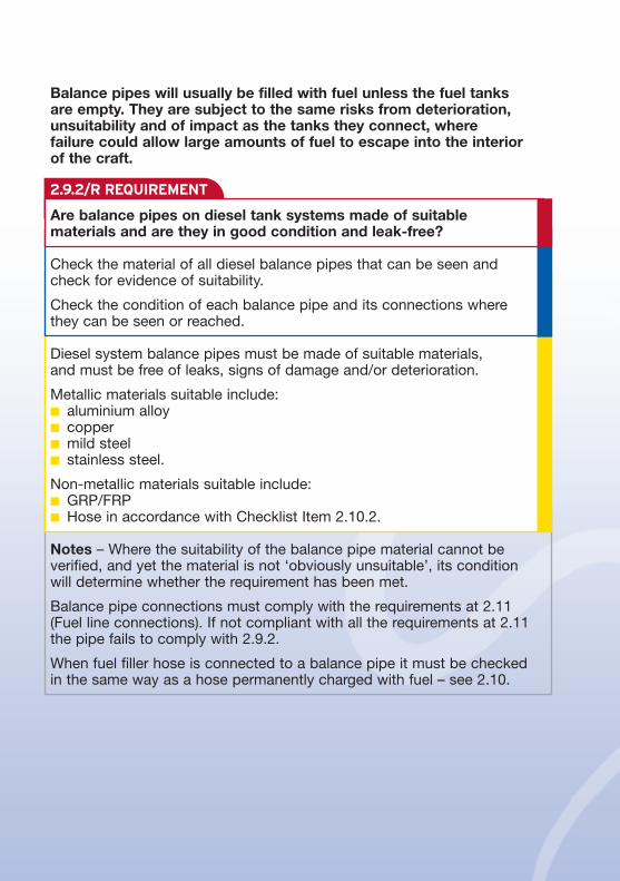
Balance pipes will usually be filled with fuel unless the fuel tanks are empty. They are subject to the same risks from deterioration,unsuitability and of impact as the tanks they connect, where failure could allow large amounts of fuel to escape into the interiorof the craft.
Are balance pipes on diesel tank systems made of suitablematerials and are they in good condition and leak-free?
Check the material of all diesel balance pipes that can be seen andcheck for evidence of suitability.
Check the condition of each balance pipe and its connections wherethey can be seen or reached.
Diesel system balance pipes must be made of suitable materials, and must be free of leaks, signs of damage and/or deterioration.
Metallic materials suitable include:n aluminium alloyn coppern mild steeln stainless steel.
Non-metallic materials suitable include:n GRP/FRPn Hose in accordance with Checklist Item 2.10.2.
Notes – Where the suitability of the balance pipe material cannot beverified, and yet the material is not ‘obviously unsuitable’, its conditionwill determine whether the requirement has been met.
Balance pipe connections must comply with the requirements at 2.11(Fuel line connections). If not compliant with all the requirements at 2.11the pipe fails to comply with 2.9.2.
When fuel filler hose is connected to a balance pipe it must be checkedin the same way as a hose permanently charged with fuel – see 2.10.

2.10.1/R REQUIREMENT
Fuel feed, return, and on-engine lines
Fixed pipes can over time become damaged and release fuel, owing to the effects of vibration and strain.
Are all rigid fuel feed and return lines made of suitable materials?
Check the material of all rigid fuel feed and return lines that can be seenand check for evidence of suitability.
Rigid fuel lines must be made of suitable materials.
Suitable materials include:n aluminium alloyn coppern mild steel (for diesel only)n stainless steel.
Note – Where its suitability cannot be verified and yet the material is notobviously unsuitable, the fuel line condition checks (2.10.3) will determinewhether requirements are met and passed at 2.10.1 and 2.10.3. If thecondition requirements at 2.10.3 are not met, the tank will fail at 2.10.1 and 2.10.3.
The useful life of flexible hose depends on many factors, includingstorage and operating conditions. It is likely that the hose may need to be changed several times during the lifetime of your boat. The risk of early failure through damage from heat and abrasion is the key factor.
2.10
BSS Essential Guide 2nd Edition Aug 2005 Ch2/Pg25

bBest practiceFlexible hose has a lower fire-resistance than metallic pipe andfor all these reasons we highly recommend that you restrict thelength of hose used in the fuel system to the absolute minimum,i.e. the minimum length necessary to cope with vibration or themovement of engines and boat structures.
2.10.2/R REQUIREMENT
Are all flexible fuel feed and return hoses suitable for the fuel usedand fire resistant?
Check the marking on all fuel feed and return hoses.
Fuel feed and return hoses must be marked, to denote both suitability for the fuel used and fire resistance, to BS EN ISO 7840 or an equivalent standard.
Notes – Hoses marked to SAE J 1527 and DIN 4798 are acceptable.
Armoured or other external braiding is not evidence of hose suitability or fire resistance. Such hoses must be marked as above.
Where a hose is not marked as meeting an accepted standard but itssuitability is claimed, evidence should be sent to the BSS Office forconsideration of the claim.
Fuel hose suitability may be supported by a written declaration from the hose manufacturer or supplier or, if appropriate, from the enginemanufacturer/supplier or mariniser.

2.10.4/R REQUIREMENT
BSS Essential Guide 2nd Edition Aug 2005 Ch2/Pg27
2.10.3/R REQUIREMENT
Leaks from insecure and poor condition lines present a risk of fireand/or explosion.
Are all fuel feed and return lines secure and in good condition?
Check the condition of all fuel feed and return lines, which can be seen or reached.
Apply light manual force to check security of all rigid fuel lines that can be reached.
Fuel feed and return lines must be free of leaks, signs of damage or deterioration.
All fuel feed and return hoses must be free of leaks, flaws, brittleness,cracking, abrasion, kinking and ‘soft spots’.
Rigid fuel feed and return lines must not move under light manual force.
Note – Pay particular attention to fuel lines etc close to hot exhausts and other sources of heat.
Failure can result if strain on the joints and the fabric of the hose caused by the weight of the hose and the fuel it carries is not prevented.
Are all flexible fuel feed and return hoses properly supported?
Check flexible fuel feed and return hoses where they can be seen or reached for support and protection.
Fuel feed and return hoses must be supported clear of anything likely to damage them, or be otherwise protected.
Note – Pay particular attention to sharp engine components, enginebearers and other vessel structures.

2.10.5/R REQUIREMENT
Some engines are unable to meet traditional marine standards of metallic pipes, or even newer standards such as the use of fire-resistant hose without modification to the injectors themselves. In order to accommodate these engines, and the original non-fire resistant plastic or rubber tubing, somealternatives are detailed below.
Do the injector leak-off (spill rail) arrangements meet specified requirements?
Check the arrangements for the injector leak-off (spill rail).
Injector leak-off (spill rail) arrangements must meet all the requirementsfor fuel feed and return pipes, flexible hose and connections; or,n utilise the direct return to tank; or,n return to the fuel system through a non-return valve.
Notes – Vintage and traditional engines designed to return the injectorleak-off fuel to a metal catch pot are acceptable provided the metalcatch pot is securely mounted and is free of leaks, signs of damage or deterioration.
Supplementary information on spill rail options is available onwww.boatsafetyscheme.com or by post or email from the BSS Office.
Injector leak-off hoses fitted by the manufacturer within an enclosure on the engine meet this requirement.
Compression Cone Flanged Screwed
Swaged Ferule
Flexible Hose
Rigid Pipe

2.11.1/R REQUIREMENT
2.11.2/R REQUIREMENT
Are all fuel line connections of the correct type and leak-free?
Check the type of fuel line connections that can be seen or reached andcheck for leaks by sight and touch.
Fuel line connections must be screwed, compression, cone, brazed or flanged.
Flexible fuel hose connections must either be pre-made end fittings onhose assemblies, or hose clips/clamps onto hose nozzles or formedpipe-ends.
Fuel line connections must be free of leaks, signs of damage or deterioration.
Notes – Soft-soldered joints are not acceptable. Where there is concern that joints may be made with soft solder, the owner mustprovide evidence that this is not the case and that the joints meet the requirements.
Injector leak-off (spill rail) arrangements having push-on connections on flexible fuel lines are acceptable for options covered by the bulletpoints at Checklist Item 2.10.5.
An insecure component is a sign of a potential weakness that could allow a fuel escape.
Are all fuel line connections, cocks, valves, fittings and othercomponents secure?
Apply light manual force to check security of all fuel line connections,cocks, valves, fittings and other components that can be reached.
Fuel line connections, cocks, valves, fittings and other components must not move under light manual force.
BSS Essential Guide 2nd Edition Aug 2005 Ch2/Pg29
Connections
Some jointing methods are intrinsically weaker than internationally recognised standards. Soft-soldered and push-on joints may fail at any time, but especially in a fire, adding more fuel to the flames.
2.11

2.11.3/R REQUIREMENT
Checks have found that the use of ineffective clamps andconnections have caused leaks.
Are flexible fuel hose connections made with hose clips or clampseffective and in good condition?
Check flexible fuel hose connections made with hose clips or clampsthat can be seen and reached. Assess their condition and look and feel for leaks.
Pull using light manual force to check security of all hose connections.
Flexible fuel hose connections made with hose clips or clamps must:n be suitably sized, that is, not so oversized that the band forms an
elliptical shape or so undersized that no tightness is achieved; and,n be appropriately tight, that is, not so loose that the connection can
be pulled forward or back under light manual force, nor so tight thatthe hose is excessively pinched; and,
n show no signs of damage or deterioration at the clip or clamp; and,n show no signs of damage or deterioration at the hose caused by the
clips or clamps.
Note – Do not apply the light manual force check to injector leak-off(spill rail) arrangements having push-on connections. Supplementaryinformation on spill rail options is available onwww.boatsafetyscheme.com or by post or email from the BSS Office.
Fuel filters
Non-marine fuel filters can be vulnerable to damage from fire andimpact damage as well as, the vibration, shock, corrosion andmovement found in marine use. The failure of a fuel filter could leadto a very significant leakage of fuel, which if the cause was a fire,could add fuel to the flames.
2.12

2.12.1/R REQUIREMENT
2.12.2/R REQUIREMENT
2.12.3/R REQUIREMENT
Are fuel filters in good condition?
Check the condition of all fuel filters.
Fuel filters must be free of leaks and signs of damage or deterioration to any part of the filter assembly.
Note – The requirements at section 2.12 must be applied to all forms of fuel filters, including water traps, sedimenters, agglomeraters, etc.
The failure of a fuel filter or its plug can lead to additional fuel beingadded to any fire.
Are all fuel filters of a suitable proprietary marine type?
Check that all fuel filters are marked or recognised as suitableproprietary marine filters. If not marked or recognised as suitable, verify this by examining any presented declaration from the manufacturer or supplier.
Fuel filters must be of a suitable proprietary marine type.
Are all fuel filters inside engine spaces fire resistant?
Check all fuel filters (including drain plugs) located inside engine spacesare marked or recognised as fire resistant. If not marked or recognisedas being suitably fire resistant, verify this by examining any presenteddeclaration from the manufacturer or supplier.
Fuel filters (including drain plugs) located inside engine spaces musthave intrinsic fire resistance of at least 21⁄2 minutes at 600ºC (1112ºF).
Note – All-metal fuel filters are considered ‘sufficiently fire resistant’.Fuel filters marked with ISO 10088 are acceptable.
BSS Essential Guide 2nd Edition Aug 2005 Ch2/Pg31

2.13.1/R REQUIREMENT
2.13.2/R REQUIREMENT
Fuel shut-offs
It is important to ensure the fuel system can be prevented fromfeeding fuel to a small incident and making it a serious one.
Is an emergency fuel shut-off installed in every fuel feed line?
Check the means to shut off the fuel in the fuel feed line from every fuel tank.
An effective emergency shut-off must be installed in all fuel feed lines.Any of the following methods are acceptable:n a manual shut-off valve or cock; or,n all fuel lines, including those on the engine, being above the level
of the top of the tank; or,n an anti-siphon valve at the tank, providing it was installed by the
boatbuilder; or,n an electrically operated valve at the tank, activated to open only
during engine starting or running, provided that a manual emergencyoperating or bypassing device is present.
Note – Claims that an emergency shut-off facility is provided by an anti-siphon valve or an electrically operated valve, need to be verifiedwith the help of the BSS Office.
An emergency fuel shut-off needs to be easy to reach and operatewithout undoing any panels, etc as soon as it is needed.
Are all fuel shut-off valves or cocks, or their means of operation, in a readily accessible position?
Check for the presence of fuel shut-off valves or cocks. If present, check their accessibility or the accessibility of their means of operation.
Fuel shut-off valves or cocks, or their means of operation, must be installed in a readily accessible position.
2.13
bBest practiceWe strongly recommend that you have some way of operatingthis valve or cock from outside your boat’s engine compartment.

2.13.3/R REQUIREMENT
2.13.4/R REQUIREMENT
New crewmembers, visitors or even fire-fighters who need to shutdown the fuel supply in an emergency must be able to identify theposition of the shut-off valve quickly.
Are all fuel shut-off valves or cocks, or their means of operation, in open view or their location clearly marked?
Check for the presence of fuel shut-off valves or cocks.
If present, check that fuel shut-off valves or cocks, or their means ofoperation, are in open view with all removable lids, deck boards,curtains, doors, etc in place.
If not in open view check their location is clearly marked in open view.
Fuel shut-off valves or cocks, or the means to operate them, mustn be in open view with all removable lids, deck boards, curtains,
doors, etc in place; or,n have their location clearly marked in open view.
Gravity-fed petrol systems present greater risks than others andmerit special measures. The speed with which petrol can ignitemeans that you may not have time to move away from the helm and if you did it could put you in greater danger.
Are petrol gravity-fed fuel lines provided with the required fuel shut-off facilities.
Check for the presence of a gravity-fed petrol installation.
If present, check that a second shut-off valve or cock, or a means ofoperating the main valve or cock, can be reached from the steeringposition and check its accessibility.
Gravity-fed petrol installations must have a second cock, or a means of operating the main cock, in a readily accessible position withinapproximately 2m (6 ft 6 in) of the steering position.
BSS Essential Guide 2nd Edition Aug 2005 Ch2/Pg33
iInformationWhen choosing a solenoid-controlled shut-off valve, seek thesupplier’s assurance as to its suitability for the fuel in use.
2.14.1/R REQUIREMENT
2.14.2/R REQUIREMENT
1
2
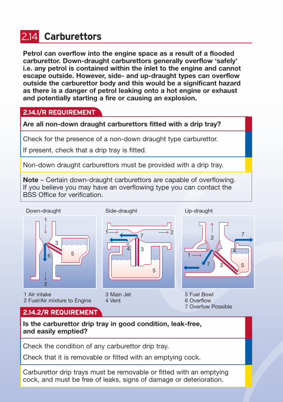
1 Air intake2 Fuel/Air mixture to Engine
5 Fuel Bowl6 Overflow7 Overfow Possible
3
4
5
7
7
34
71 2
5
5
3
2
1
6
Down-draught Side-draught Up-draught
Carburettors
Petrol can overflow into the engine space as a result of a floodedcarburettor. Down-draught carburettors generally overflow ‘safely’i.e. any petrol is contained within the inlet to the engine and cannotescape outside. However, side- and up-draught types can overflowoutside the carburettor body and this would be a significant hazardas there is a danger of petrol leaking onto a hot engine or exhaustand potentially starting a fire or causing an explosion.
Are all non-down draught carburettors fitted with a drip tray?
Check for the presence of a non-down draught type carburettor.
If present, check that a drip tray is fitted.
Non-down draught carburettors must be provided with a drip tray.
Note – Certain down-draught carburettors are capable of overflowing. If you believe you may have an overflowing type you can contact theBSS Office for verification.
Is the carburettor drip tray in good condition, leak-free, and easily emptied?
Check the condition of any carburettor drip tray.
Check that it is removable or fitted with an emptying cock.
Carburettor drip trays must be removable or fitted with an emptyingcock, and must be free of leaks, signs of damage or deterioration.
2.14
3 Main Jet4 Vent

2.14.3/R REQUIREMENT
2.14.4/R REQUIREMENT
Without protection fixed to the drip tray, flames produced as a resultof an engine backfire could ignite any spilt fuel.
Is the carburettor drip tray fitted with effective flame-arrestinggauze permanently attached along all edges?
Check the carburettor drip tray gauze for effectiveness by comparing it with a sample of gauze of the correct mesh.
Check the condition of the gauze and the method of attachment to the tray.
Carburettor drip tray gauze must have a mesh of at least 11 wires per linear cm (28 wires per inch).
Gauze must be complete and free of restrictions, damage, and must be permanently and continuously attached to the tray along all edges.
Is a petrol, petroil or paraffin engine fitted with flame trap or air filter?
Identify the air intake of petrol, petroil and paraffin engines and look for the presence of a flame trap or air filter.
Petrol, petroil and paraffin engines must have a flame trap or air filterfitted to the air intake.
Note – The BSS examination does not include for dismantling the airfilter to determine the nature of the filter element, if any.
Engine installation
Undue movement of the engine may place a strain on the fuelsystem and lead to fuel escapes.
2.15
BSS Essential Guide 2nd Edition Aug 2005 Ch2/Pg35
iInformation – Oil-tight trayPollution prevention is a requirement. Please read Chapter 9 forthe requirements in regard to anti-pollution protection includingthe need for an oil-tight tray or similar oil discharge measures.
2.15.1/R REQUIREMENT
2.15.2/R REQUIREMENT
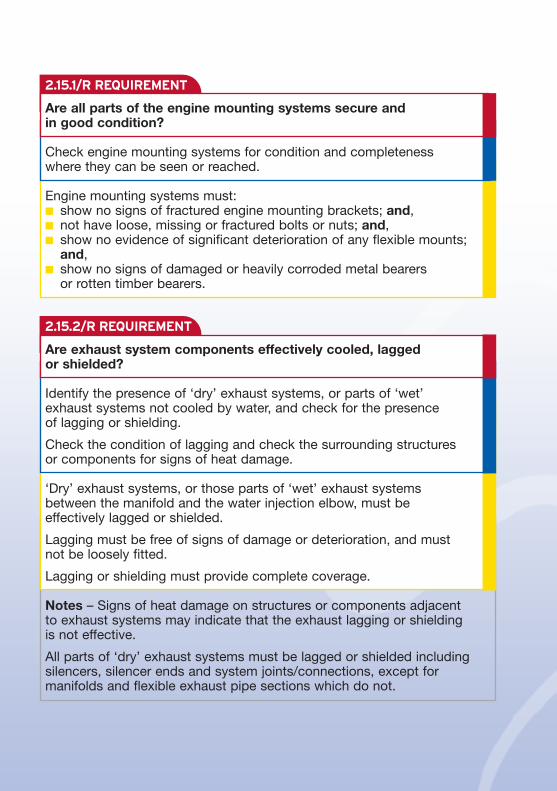
Are all parts of the engine mounting systems secure and in good condition?
Check engine mounting systems for condition and completeness where they can be seen or reached.
Engine mounting systems must:n show no signs of fractured engine mounting brackets; and,n not have loose, missing or fractured bolts or nuts; and,n show no evidence of significant deterioration of any flexible mounts;
and,n show no signs of damaged or heavily corroded metal bearers
or rotten timber bearers.
Are exhaust system components effectively cooled, lagged or shielded?
Identify the presence of ‘dry’ exhaust systems, or parts of ‘wet’ exhaust systems not cooled by water, and check for the presence of lagging or shielding.
Check the condition of lagging and check the surrounding structures or components for signs of heat damage.
‘Dry’ exhaust systems, or those parts of ‘wet’ exhaust systems between the manifold and the water injection elbow, must be effectively lagged or shielded.
Lagging must be free of signs of damage or deterioration, and must not be loosely fitted.
Lagging or shielding must provide complete coverage.
Notes – Signs of heat damage on structures or components adjacent to exhaust systems may indicate that the exhaust lagging or shielding is not effective.
All parts of ‘dry’ exhaust systems must be lagged or shielded includingsilencers, silencer ends and system joints/connections, except formanifolds and flexible exhaust pipe sections which do not.

2.16.1/R REQUIREMENT
2.16.2/R REQUIREMENT
Steam-powered engines
Is the steam engine pressure system supported by an inspectioncertificate issued by a competent person?
Read carefully the steam engine pressure-system inspection certificate.Check the validity of the certificate and check the terminology indicatesthe pressure system is in a satisfactory condition.
Steam engine pressure systems must be supported by an inspectioncertificate. Pressure-system inspection certificates must:n relate to the vessel being examined;n be completed by a competent person;n indicate satisfactory condition;n must be less than 14 months old or within any ‘run-out’ date.
Note – Guidance on the assessment of pressure-system inspectioncertificates is available on www.boatsafetyscheme.com or by post oremail from the BSS Office.
Is the steam engine boiler fuel supply system compliant with theapplicable BSS requirements?
Identify the type of fuel to the steam engine boiler.
Apply the relevant Part of the BSS requirements to the fuel supply system.
Steam engine boiler fuel supply systems must be compliant with theapplicable BSS requirements.
2.16
BSS Essential Guide 2nd Edition Aug 2005 Ch2/Pg37
bBest practiceTo minimise the risk of a potential pressure system explosion, a steam-powered engine needs to have regular checks andcomply with industry practice.
For your own protection, it is recommended that the pressure system is covered for third-party risks by a currentinsurance policy.
2.17.1/R REQUIREMENT
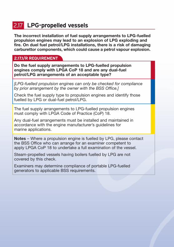
LPG-propelled vessels
The incorrect installation of fuel supply arrangements to LPG-fuelledpropulsion engines may lead to an explosion of LPG exploding andfire. On duel fuel petrol/LPG installations, there is a risk of damagingcarburettor components, which could cause a petrol vapour explosion.
Do the fuel supply arrangements to LPG-fuelled propulsion engines comply with LPGA CoP 18 and are any dual-fuel petrol/LPG arrangements of an acceptable type?
[LPG-fuelled propulsion engines can only be checked for compliance by prior arrangement by the owner with the BSS Office.]
Check the fuel supply type to propulsion engines and identify thosefuelled by LPG or dual-fuel petrol/LPG.
The fuel supply arrangements to LPG-fuelled propulsion engines must comply with LPGA Code of Practice (CoP) 18.
Any dual-fuel arrangements must be installed and maintained inaccordance with the engine manufacturer’s guidelines for marine applications.
Notes – Where a propulsion engine is fuelled by LPG, please contact the BSS Office who can arrange for an examiner competent to apply LPGA CoP 18 to undertake a full examination of the vessel.
Steam-propelled vessels having boilers fuelled by LPG are not covered by this check.
Examiners may determine compliance of portable LPG-fuelledgenerators to applicable BSS requirements.
2.17