fixation of carbon dioxide by producing carbonates from - aaltodoc
TRANSCRIPT
TKK Dissertations 119Espoo 2008
FIXATION OF CARBON DIOXIDE BY PRODUCING CARBONATES FROM MINERALS AND STEELMAKING SLAGSDoctoral Dissertation
Helsinki University of TechnologyFaculty of Engineering and ArchitectureDepartment of Energy Technology
Sebastian Teir
TKK Dissertations 119Espoo 2008
FIXATION OF CARBON DIOXIDE BY PRODUCING CARBONATES FROM MINERALS AND STEELMAKING SLAGSDoctoral Dissertation
Sebastian Teir
Dissertation for the degree of Doctor of Science in Technology to be presented with due permission of the Faculty of Engineering and Architecture for public examination and debate in Auditorium K216 at Helsinki University of Technology (Espoo Finland) on the 2nd of June 2008 at 12 noon
Helsinki University of TechnologyFaculty of Engineering and ArchitectureDepartment of Energy Technology
Teknillinen korkeakouluInsinoumloumlritieteiden ja arkkitehtuurin tiedekuntaEnergiatekniikan laitos
DistributionHelsinki University of TechnologyFaculty of Engineering and ArchitectureDepartment of Energy TechnologyPO Box 4400FI - 02015 TKKFINLANDURL httpenytkkfiTel +358-9-451 3631Fax +358-9-451 3418E-mail sebastianteirvttfi
copy 2008 Sebastian Teir
ISBN 978-951-22-9352-0ISBN 978-951-22-9353-7 (PDF)ISSN 1795-2239ISSN 1795-4584 (PDF) URL httplibtkkfiDiss2008isbn9789512293537
TKK-DISS-2461
Picaset OyHelsinki 2008
AB
ABSTRACT OF DOCTORAL DISSERTATION HELSINKI UNIVERSITY OF TECHNOLOGY PO BOX 1000 FI-02015 TKK httpwwwtkkfi
Author Sebastian Teir
Name of the dissertation Fixation of carbon dioxide by producing carbonates from minerals and steelmaking slags
Manuscript submitted December 12th 2007 Manuscript revised March 31st 2008
Date of the defence June 2nd 2008
Monograph Article dissertation (summary + original articles)
Faculty Faculty of Engineering and Architecture Department Department of Energy Technology Field of research Carbon dioxide capture and storage Opponent(s) Marco Mazzotti Prof and Olav Eklund Prof Supervisor Carl-Johan Fogelholm Prof Instructor Ron Zevenhoven Prof
Abstract Capture and storage of carbon dioxide (CO2) is internationally considered to be one of the main options for reducing atmospheric emissions of CO2 In Finland no suitable geological formations are known to exist for storing captured CO2 However fixing CO2 as solid carbonates using silicate-based materials is an interesting alternative The magnesium silicate deposits in Eastern Finland alone could be sufficient for storing 10 Mt CO2 each year during a period of 200-300 years Finnish steelmaking slags could also be carbonated but the amounts produced provide a much smaller potential for CO2 storage (05 Mt CO2 per year) than magnesium silicates provide The aim of this thesis was to study the possibility of reducing CO2 emissions by producing calcium and magnesium carbonates from silicate materials for the long-term storage of CO2 using multi-step processes The production of carbonates from steelmaking slags and serpentinite a magnesium silicate ore available from a metal-mining site was studied both experimentally and theoretically On the basis of the results process concepts were developed and evaluated Finally the stability of synthetic calcium and magnesium carbonates as a medium for CO2 storage was assessed Experiments with aqueous extraction and precipitation processes showed that magnesium and calcium can easily be extracted from steelmaking slags and natural silicate minerals using acids Natural minerals seem to demand stronger acids for extraction than slags Relatively pure calcium carbonate (80-90 calcite) was produced at room temperature and a CO2 pressure of 1 bar by adding sodium hydroxide to acetate solutions made from slag Similarly serpentinite was successfully converted into 93-100 pure hydromagnesite (a magnesium carbonate) using nitric acid or hydrochloric acid for the dissolution of serpentinite and sodium hydroxide for precipitation The conversion of raw material to carbonate ranged from 60-90 Although the results show that pure carbonates can be produced from industrial by-products and mining residues the process concept suggested requires the recycling of large amounts of sodium hydroxide and acid as well as low-grade heat for solvent evaporation The methods suggested for recovering the spent chemicals were found to be expensive and cause more CO2 emissions than the amount of CO2 stored
Keywords mineral carbonation slag carbon dioxide dissolution precipitation carbonate
ISBN (printed) 978-951-22-9352-0 ISSN (printed) 1795-2239
ISBN (pdf) 978-951-22-9353-7 ISSN (pdf) 1795-4584
Language English Number of pages 106 p + app 93 p
Publisher Helsinki University of Technology Department of Energy Technology
Print distribution Helsinki University of Technology Department of Energy Technology
The dissertation can be read at httplibtkkfiDiss
AB
SAMMANFATTNING (ABSTRAKT) AV DOKTORSAVHANDLING
TEKNISKA HOumlGSKOLAN PB 1000 FI-02015 TKK httpwwwtkkfi
Foumlrfattare Sebastian Teir
Titel Bindning av koldioxid genom produktion av karbonater fraringn mineraler och staringlslagg
Inlaumlmningsdatum foumlr manuskript 12122007 Datum foumlr disputation 262008
Datum foumlr det korrigerade manuskriptet 3132008
Monografi Sammanlaumlggningsavhandling (sammandrag + separata publikationer)
Fakultet Fakulteten foumlr ingenjoumlrsvetenskaper och arkitektur Institution Institutionen foumlr energiteknik Forskningsomraringde Infaringngning och lagring av koldioxid Opponent(er) Marco Mazzotti Prof och Olav Eklund Prof Oumlvervakare Carl-Johan Fogelholm Prof Handledare Ron Zevenhoven Prof
Sammanfattning (Abstrakt) Infaringngning och lagring av koldioxid (CO2) anses paring internationell nivaring som en av de huvudsakliga alternativen foumlr att minska paring utslaumlppen av koldioxid till atmosfaumlren I Finland finns det inga kaumlnda geologiska formationer laumlmpliga foumlr lagring av infaringngad koldioxid Bindning av koldioxid som fasta karbonater genom anvaumlndning av silikatbaserade material aumlr emellertid ett intressant alternative Magnesiumsilikatfyndigheterna i enbart Oumlstra Finland kunde raumlcka till foumlr att aringrligen lagra 10 Mt CO2 under en period paring 200 ndash 300 aringr Finsk staringlslagg kunde ocksaring karboneras men produktionsmaumlngden kunde staring foumlr en mycket mindre koldioxidlagringspotential (05 Mt CO2 per aringr) aumln vad magnesiumsilikaterna kunde staring foumlr Maringlsaumlttningen foumlr avhandlingen var att studera moumljligheten att minska paring koldioxidutslaumlppen genom att tillverka kalcium- och magnesiumkarbonater fraringn silikatmaterial med flerstegsprocesser foumlr laringngtidslagring av koldioxid Tillverkningen av karbonater fraringn staringlslagg och serpentinit en magenesiumsilikatmalm som aumlr tillgaumlnglig fraringn en metallgruva studerades experimentellt och teoretiskt Paring basen av resultaten utvecklades och evaluerades ett processkoncept Slutligen faststaumllldes stabiliten av syntetiska kalcium- och magnesiumkarbonater som koldioxidlagringsmedia Experiment med vaumltskeutvinnings- och utfaumlllningsprocesser visade att kalcium och magnesium kan laumltt utvinnas fraringn staringlslagg och naturliga silikatmineraler genom att anvaumlnda syror Naturliga mineraler verkar kraumlva starkare syror foumlr utvninning aumln vad slagg kraumlver En raumltt saring ren kalciumkarbonat (80 ndash 90 kalcit) faumllldes ut vid rumstemperatur och 1 bar CO2 tryck genom att tillsaumltta natriumhydroxid till acetatloumlsningar tillverkade fraringn slagg Paring liknande vis konverterades serpentinite till 93 ndash 100 ren hydromagnesit (en form av magnesiumkarbonat) genom att anvaumlnda salpetersyra eller saltsyra foumlr att loumlsa serpentiniten och natriumhydroxid foumlr utfaumlllningen Konversionen fraringn raringmaterial till karbonat uppgick till 60 ndash 90 Fastaumln resultaten visar att ren karbonat kan produceras fraringn industriella sidoprodukter och gruvdriftsresidual kraumlver processkonceptet aringtervinning av stora maumlngder av natriumhydroxid och syra samt laringgkvalitetsvaumlrme foumlr foumlraringngning av loumlsningsmedel Foumlreslagna metoder foumlr aringtervinning av anvaumlnda kemikalier konstaterades kostsamma och skulle ge upphov till mera koldioxidutslaumlpp aumln den lagrade maumlngden
Aumlmnesord (Nyckelord) mineralkarbonering slagg koldioxid loumlsning utfaumlllning karbonat
ISBN (tryckt) 978-951-22-9352-0 ISSN (tryckt) 1795-2239
ISBN (pdf) 978-951-22-9353-7 ISSN (pdf) 1795-4584
Spraringk Engelska Sidantal 106 p + app 93 p
Utgivare Tekniska houmlgskolan Institutionen foumlr energiteknik
Distribution av tryckt avhandling Tekniska houmlgskolan Institutionen foumlr energiteknik
Avhandlingen aumlr tillgaumlnglig paring naumltet httplibtkkfiDiss
Preface Before you continue to read this thesis I would ask you to take time and reflect upon
one of the most serious threats that mankind has ever created for itself Human activities have
released so much CO2 into the atmosphere that the current level has not been reached in the
last 650000 years and still the emissions keep increasing The latest reports from
international experts stress the importance of stabilising our CO2 emissions within the next
20-30 years The urgency of reducing our CO2 emissions has been my main motivation for
carrying out this work Considerable advances in technology for mitigating climate change
are needed that will limit our CO2 emissions considerably Recent research has also shown
that reducing our carbon footprint now will cost us much less than trying to reduce it in 20-30
yearsrsquo time Although global climate change is a serious threat its mitigation is an important
opportunity for global co-operation on a scale that has never been carried out before We
would save not only our environment but also our economy and our future
The work presented in this thesis was carried out in the framework of three projects
ldquoNordic CO2 sequestrationrdquo (NoCO2 2003-2007) funded by Nordic Energy Research as well
as ldquoCO2 Nordic Plusrdquo (2003-2005) and ldquoSlag2PCCrdquo (2005-2007) funded by the Finnish
Funding Agency for Technology and Innovation (TEKES) the Finnish Recovery Boiler
Committee Ruukki UPM and Waumlrtsilauml The projects were also supported by the Geological
Survey of Finland Outokumpu Aker Kvaerner Enprima Foster-Wheeler Energy Fortum
and Nordkalk The Academy of Finlandrsquos ldquoProDOErdquo-project (2007-2010) is also
acknowledged for support during the final stages of writing this thesis I also thank the
Graduate School in Energy Technology for a scholarship during 2007 as well as the Walter
Ahlstroumlm foundation Vasa Nation and the Foundation for Promotion of Technology (TES)
for research grants
First I want to thank Ron Zevenhoven and Carl-Johan Fogelholm for supervising my
thesis work I am grateful to them for the opportunity to work with such an interesting topic I
especially wish to thank my co-workers Sanni Eloneva Hannu Revitzer Justin Salminen
Tuulia Raiski and Jaakko Savolahti for their valuable assistance and discussions I wish to
thank Marco Mazzotti and Jarl Ahlbeck for providing statements for the pre-examination of
my thesis Thanks go also to Mika Jaumlrvinen for proof-reading my thesis I would also like to
thank Rein Kuusik Mai Uibu and Valdek Mikli at Tallinn University of Technology for
assistance as well as for a very educational and productive visit at their university Special
thanks go to Pertti Kiiski Vadim Desyatnyk Loay Saeed Seppo Markelin and Taisto
Nuutinen for technical assistance Thanks also go to the rest of the personnel at the laboratory
for contributing to the good spirit in the laboratory I also want to thank Kari Saari for
iv
providing part of the equipment needed for the experiments and Rita Kallio for analysis
services I thank Soile Aatos Peter Sorjonen-Ward and Olli-Pekka Isomaumlki for discussion and
information about serpentinites I also thank the people at Ruukki Ovako Outokumpu
Nordkalk and Dead Sea Periclase for providing us with slag and mineral samples for our
experiments Special thanks also go to all my colleagues and friends in the projects I thank
my parents Mona-Lisa and Henrik as well as my sister Sabina for their love and the support
they continue to give me and my friends for giving me something else to think about Finally
I want to thank Heidi for giving me her love support strength uncompromised opinions and
inspiration
Sebastian Teir
Espoo 21st April 2008
v
List of publications
I TEIR S ELONEVA S ZEVENHOVEN R 2005 Production of precipitated
calcium carbonate from calcium silicates and carbon dioxide Energy Conversion and
Management 46 2954-2979
II TEIR S ELONEVA S FOGELHOLM C-J ZEVENHOVEN R 2007
Dissolution of Steelmaking Slags in Acetic Acid for Precipitated Calcium Carbonate
Production Energy 32(4) 528-539
III ELONEVA S TEIR S SAVOLAHTI J FOGELHOLM C-J ZEVENHOVEN
R 2007 Co-utilisation of CO2 and Calcium Silicate-rich Slags for Precipitated
Calcium Carbonate Production (Part II) In Proceedings of ECOS 2007 Padua Italy
25-28 June 2007 Volume II 1389-1396 (submitted in a reworked form to Energy
March 2007)
IV TEIR S REVITZER H ELONEVA S FOGELHOLM C-J ZEVENHOVEN R
2007 Dissolution of natural serpentinite in mineral and organic acids International
Journal of Mineral Processing 83(1-2) 36-46
V TEIR S KUUSIK R FOGELHOLM C-J ZEVENHOVEN R 2007 Production
of magnesium carbonates from serpentinite for long-term storage of CO2 International
Journal of Mineral Processing 85(1-3) 1-15
VI TEIR S ELONEVA S FOGELHOLM C-J ZEVENHOVEN R 2007
Carbonation of minerals and industrial by-products for CO2 sequestration In
Proceedings of IGEC-III 2007 The Third International Green Energy Conference June
17-21 2007 Vaumlsterarings Sweden ISBN 978-91-85485-53-6 (CD-ROM) (a reworked
version of this paper has been accepted for publication in Applied Energy March 2008)
VII TEIR S ELONEVA S FOGELHOLM C-J ZEVENHOVEN R 2006 Stability of
Calcium Carbonate and Magnesium Carbonate in Rainwater and Nitric Acid Solutions
Energy Conversion and Management 47 3059-3068
vi
The authorrsquos contribution to the appended publications
I Sebastian Teir was responsible for planning and performing the process modelling and
calculation work The author also carried out half of the literature review while the
other half was carried out by Sanni Eloneva The author was also responsible for the
interpretation of the results and writing the paper
II Sebastian Teir planned and carried out the experiments as well as the interpretation of
the results in collaboration with Sanni Eloneva Sebastian Teir carried out the
thermodynamic calculations and wrote most of the article
III Sebastian Teir planned and carried out the experiments in collaboration with Sanni
Eloneva and assisted her with the interpretation of the results
IV Sebastian Teir was responsible for all the experimental work except for the solvent
selection experiment series which was carried out by Hannu Revitzer Sebastian Teir
was responsible for planning the research the experimental design the interpretation of
the results performing the kinetic analysis and writing the paper
V Sebastian Teir was responsible for planning the research the experimental design
performing the experiments the interpretation of the results and writing the paper
VI Sebastian Teir was responsible for the process evaluation the interpretation of the TGA
analysis results and writing the paper
VII Sebastian Teir planned and carried out the experiments as well as the interpretation of
the results in collaboration with Sanni Eloneva Sebastian Teir wrote most of the article
and carried out all the thermodynamic calculations
vii
Table of contents Abstract iii Preface iv List of publications vi The authorrsquos contribution to the appended publications vii Table of contents viii Nomenclature x 1 Introduction 1
11 Capture and storage of CO2 2 12 Mineral carbonation 6
2 Objective of this thesis 8 3 Literature review 10
31 Suitable raw materials 10 311 Natural calcium silicates 11 312 Natural magnesium silicates 12 313 Alkaline solid waste materials 14
32 Carbonation processes 16 321 Weathering of rocks 17 322 Direct carbonation 18 323 Indirect carbonation 21 324 Carbonation of industrial residues and by-products 27 325 Production of precipitated calcium carbonate 29
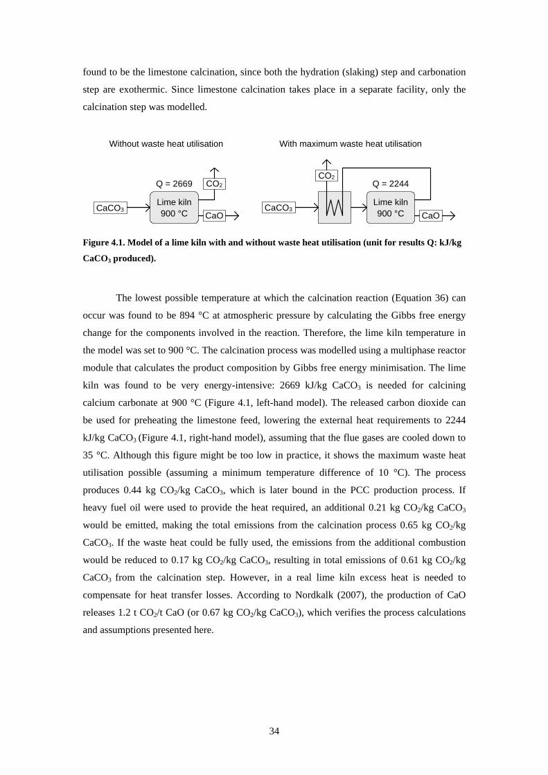
33 Utilisation of carbonate products 31 4 Production of PCC from calcium silicates ndash concept and potential 33
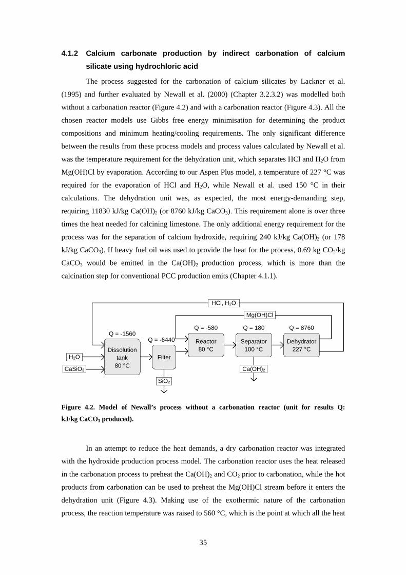
41 Process comparison and evaluation 33 411 PCC production from limestone 33 412 Calcium carbonate production by indirect carbonation of calcium silicate using
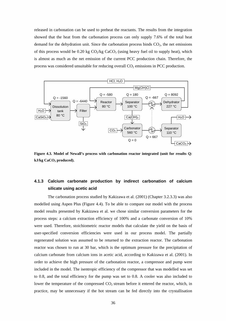
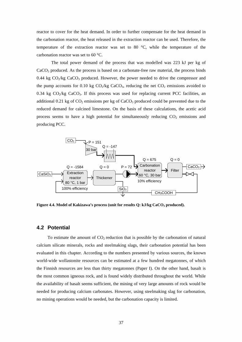
hydrochloric acid 35 413 Calcium carbonate production by indirect carbonation of calcium silicate using
acetic acid 36 42 Potential 37 43 Discussion 40
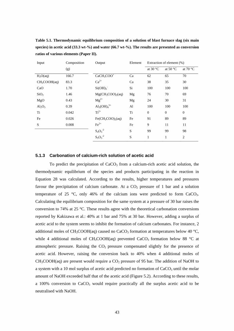
5 Production of calcium carbonate from steelmaking slag 41 51 Thermodynamic calculations 41
511 Equilibrium of reaction equations 41
viii
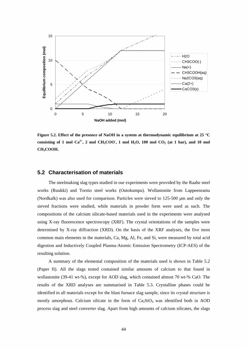
512 Dissolution of blast furnace slag 42 513 Carbonation of calcium-rich solution of acetic acid 43
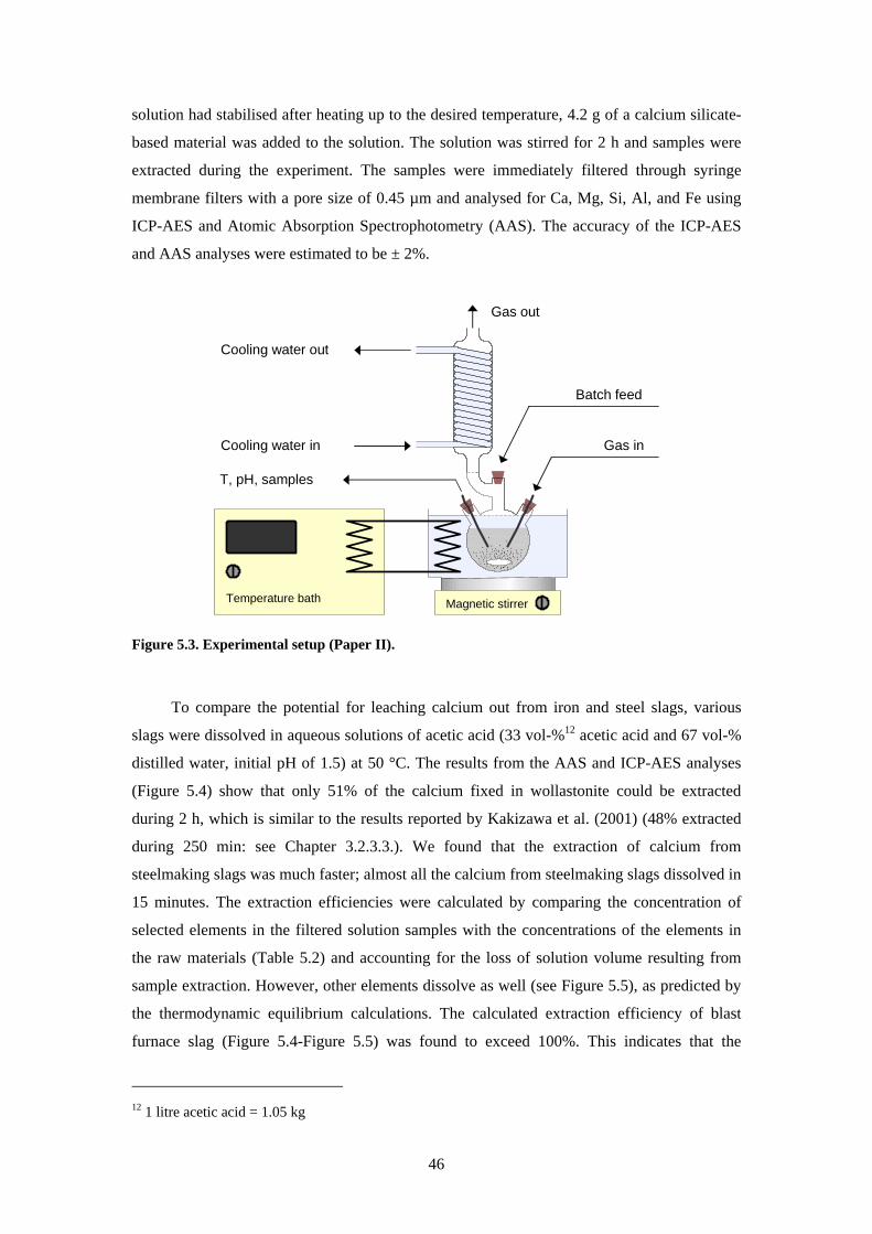
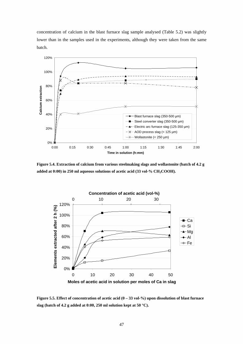
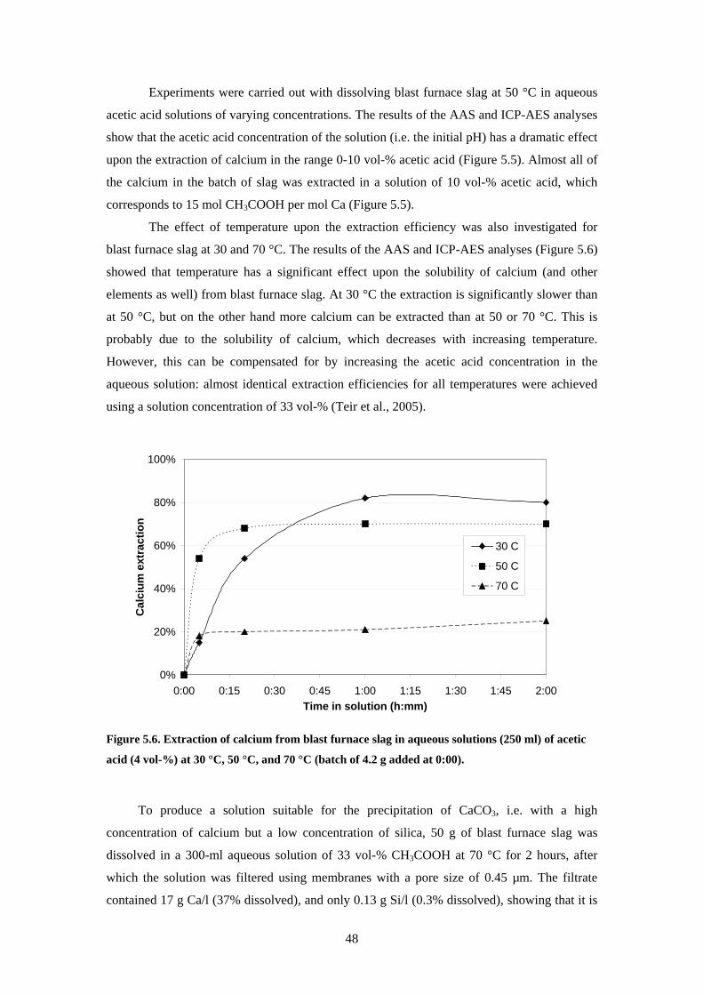
52 Characterisation of materials 44 53 Dissolution of steelmaking slags 45 54 Precipitation of carbonates 49
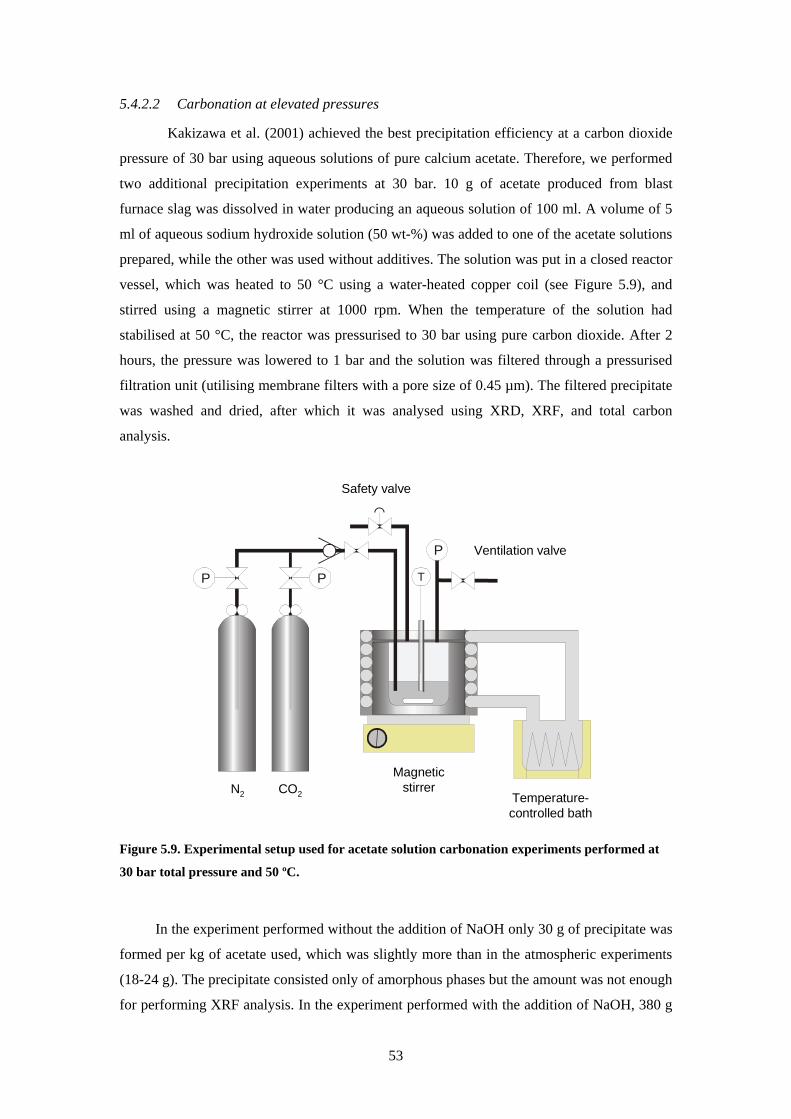
541 Carbonation of dissolved blast furnace slag 49 542 Carbonation of acetates derived from blast furnace slag 50
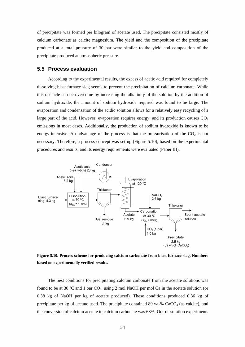
55 Process evaluation 54 56 Discussion 57
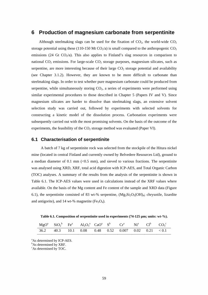
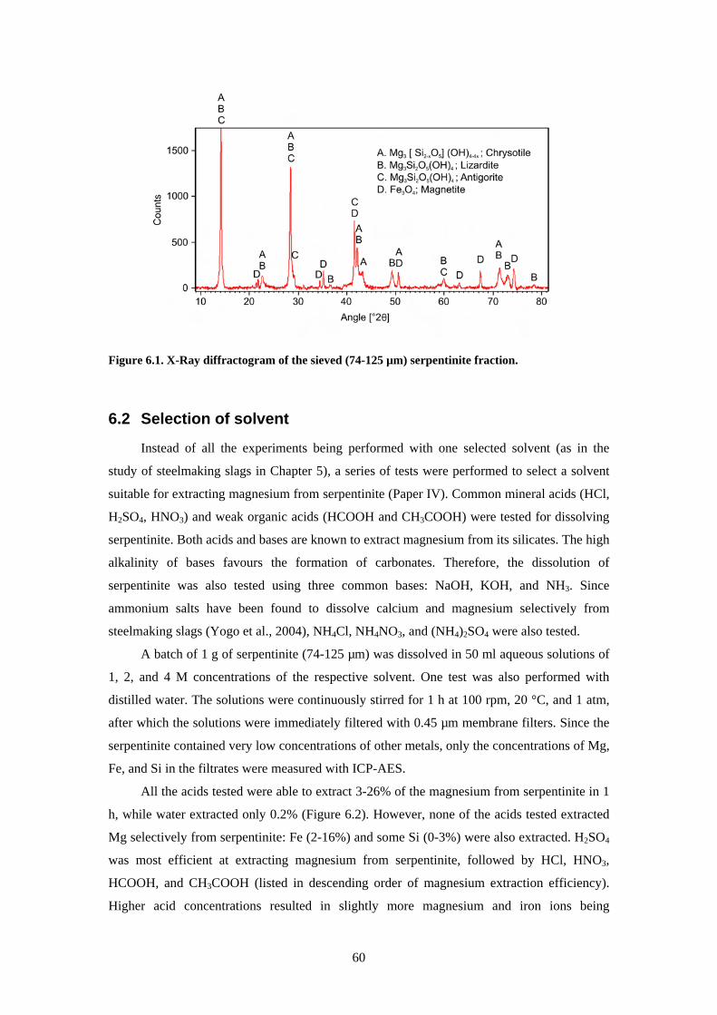
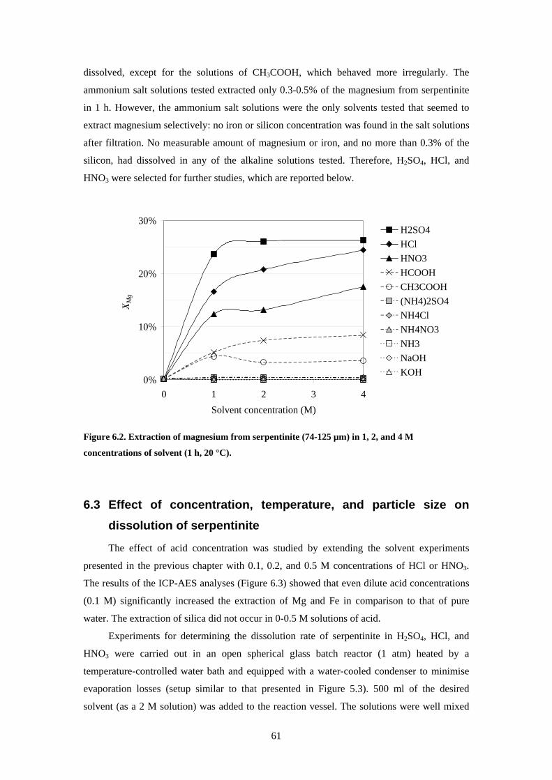
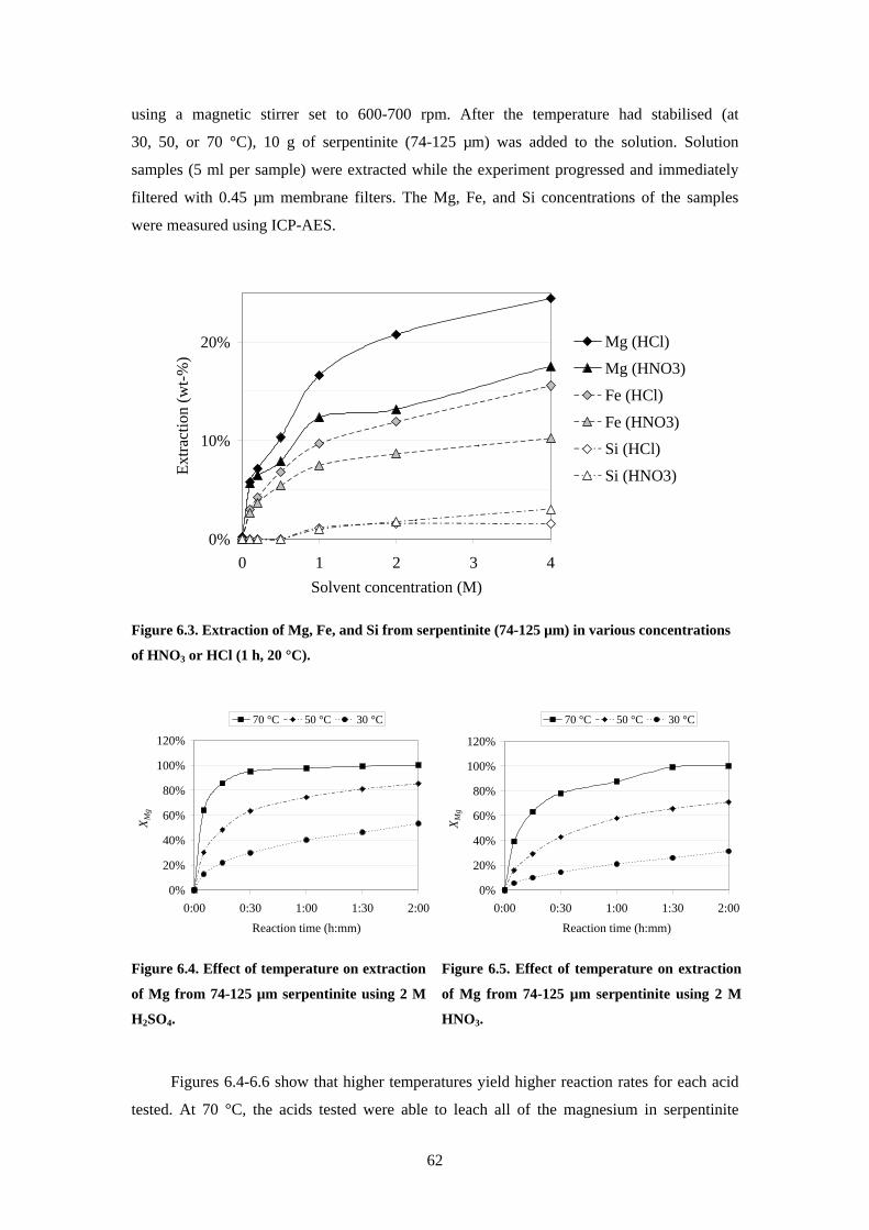
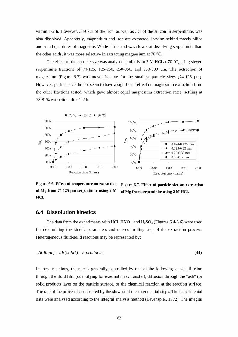
6 Production of magnesium carbonate from serpentinite 59 61 Characterisation of serpentinite 59 62 Selection of solvent 60 63 Effect of concentration temperature and particle size on dissolution of serpentinite
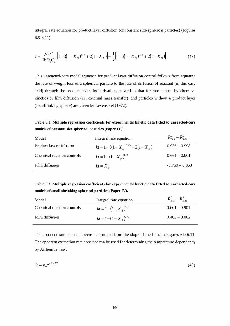
61 64 Dissolution kinetics 63 65 Precipitation of carbonates 68 66 Process evaluation 71 67 Discussion 75
7 Stability of calcium carbonate and magnesium carbonate 77 71 Stability of carbonates in rainwater and solutions of nitric acid 78 72 Stability of synthetic hydromagnesite 79 73 Discussion 80
8 Conclusions 82 81 Significance of this work 84 82 Recommendations for future work 85
References 86
ix
Nomenclature Abbreviations
AAS Atomic absorption spectrophotometry
AOD Argon-oxygen decarburisation
BOF Basic oxygen furnace
CCS Carbon dioxide capture and storage
EAF Electric arc furnace
ECBM Enhanced coal bed methane recovery
EOR Enhanced oil recovery
FT-IR Fourier transform ndash infrared spectroscopy
ICP-AES Inductively coupled plasma ndash atomic emission spectrometry
PCC Precipitated calcium carbonate
SEM Scanning electron microscope
TC Total carbon content
TGA Thermogravimetric analysis
TOC Total organic carbon content
XRD X-Ray diffraction
XRF X-Ray fluorescence
Chemical compounds minerals and rocks
Al2O3 Aluminum oxide
Ca(CH3COO)2 Calcium acetate
CaCl2 Calcium chloride
CaCO3 Calcium carbonate (calcite aragonite vaterite) limestone
CaO Calcium oxide lime
Ca(OH)2 Calcium hydroxide hydrated lime
CaSiO3 Calcium metasilicate wollastonite
CH3COOH Acetic acid
CH3COONa Sodium acetate
CO2 Carbon dioxide
EDTA Ethylenediaminetetraacetic acid
FeCO3 Iron (II) carbonate siderite
Fe2O3 Iron (III) oxide hematite
x
Fe3O4 Iron (III) oxide magnetite
Fe2SiO4 Iron (II) orthosilicate fayalite
HCl Hydrochloric acid
H2CO3 Carbonic acid
HCOOH Formic acid
HF Hydrofluoric acid
HNO3 Nitric acid
H2SO4 Sulphuric acid
KOH Potassium hydroxide
Mg(CH3COO)2 Magnesium acetate
MgCl2 Magnesium chloride
MgCl26H2O Magnesium chloride hexahydrate
MgCO3 Magnesium carbonate magnesite
MgCO33H2O Magnesium carbonate trihydrate nesquehonite
MgCO35H2O Magnesium carbonate pentahydrate lansfordite
Mg5(CO3)4(OH)24H2O Magnesium carbonate hydromagnesite
Mg(NO3)2 Magnesium nitrate
Mg(NO3)26H2O Magnesium nitrate hexahydrate
MgO Magnesium oxide periclase
Mg(OH)2 Magnesium hydroxide brucite
Mg(OH)Cl Magnesium hydroxide chloride
MgSO4 Magnesium sulphate
MgSiO3 Magnesium metasilicate enstatite
Mg2SiO4 Magnesium orthosilicate olivine (fosterite)
Mg3Si2O5(OH)4 Serpentine (chrysotile lizardite antigorite)
NH3 Ammonia
NH4Cl Ammonium chloride
NH4NO3 Ammonium nitrate
NH4OH Ammonium hydroxide
(NH4)2SO4 Ammonium sulphate
(NH4)2CO3 Ammonium carbonate
NaCl Sodium chloride
Na2CO3 Sodium carbonate
NaHCO3 Sodium bicarbonate
NaNO3 Sodium nitrate
NaOH Sodium hydroxide caustic soda
SiO2 Silicon dioxide silica
xi
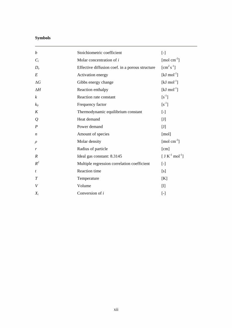
Symbols
b Stoichiometric coefficient [-]
Ci Molar concentration of i [mol cm-3]
De Effective diffusion coef in a porous structure [cm2 s-1]
E Activation energy [kJ mol-1]
∆G Gibbs energy change [kJ mol-1]
∆H Reaction enthalpy [kJ mol-1]
k Reaction rate constant [s-1]
k0 Frequency factor [s-1]
K Thermodynamic equilibrium constant [-]
Q Heat demand [J]
P Power demand [J]
n Amount of species [mol]
ρ Molar density [mol cm-3]
r Radius of particle [cm]
R Ideal gas constant 83145 [ J K-1 mol-1]
R2 Multiple regression correlation coefficient [-]
t Reaction time [s]
T Temperature [K]
V Volume [l]
Xi Conversion of i [-]
xii
1 Introduction Since the mid-19th century the global average surface temperature has increased by
almost one degree Celsius which is likely to be the largest increase in temperature during the
past 1300 years (IPCC 2007) Eleven of the last twelve years (1995-2006) were among the 12
warmest years since 1850 A few of the visible impacts of climate change are the widespread
retreat of mountain glaciers the rise in the global average sea level and the increasing
frequency and intensity of droughts in recent decades While natural changes in the climate
are common it is now very likely that human activities have attributed significantly to the
warming of the climate since the year 1750
Certain gases in the atmosphere mainly carbon dioxide (CO2) and water vapour trap
infrared (heat) radiation from the Earthrsquos surface while letting solar radiation pass through
This heat-trapping mechanism called the natural greenhouse effect helps to keep the Earthrsquos
surface temperature which otherwise would be around -19 degC at an average of 14 degC
However during the last two centuries the concentration of greenhouse gases (most
importantly CO2 but also methane nitrous oxide and fluorinated gases) and aerosols in the
atmosphere has increased drastically as a result of human activities According to data
collected from ice cores the current atmospheric concentration of CO2 (380 ppm) exceeds by
far the natural range over the last 650000 years (180 to 300 ppm) (IPCC 2007) Emissions of
greenhouse gases are expected to continue to rise and strengthen the greenhouse effect which
is projected to lead to a rise in the average temperature of 1-6 degC during the next century
(IPCC 2001b)
The main source of anthropogenic CO2 emissions (about three-quarters) is the
combustion of fossil fuel The rest is mainly due to land use changes especially deforestation
Several industrial processes (such as oil refining and the manufacturing of cement lime and
steel) are also significant sources of CO2 The annual anthropogenic CO2 emissions are
currently about 26 Gt1 CO2 (IPCC 2007)
Significant technological developments in reducing greenhouse gas emissions have been
achieved during recent decades Technological options for the reduction of emissions include
more effective energy use improved energy conversion technologies a shift to low-carbon or
renewable biomass fuels a shift to nuclear power zero-emissions technologies improved
energy management the reduction of industrial by-product and process gas emissions and
carbon capture and storage (IPCC 2001a) However according to IPCC none of these
options alone can achieve the required reductions in greenhouse gas emissions Instead a
1 1 Gt = 1000 Mt = 1000000 kt = 1000000000 tonne
1
combination of these mitigation measures will be needed to achieve a stabilisation of the
greenhouse gas concentration in the atmosphere
According to the commitments under the 1997 Kyoto Protocol industrial countries
should reduce their greenhouse gas emissions by an average of 5 from their 1990 levels
during 2008-2012 (Ministry of the Environment 2001) The Kyoto protocol binds Finland to
reduce its greenhouse emissions to their 1990 level (771 Mt CO2 equivalent excluding land
use changes and forestry) According to the Ministry of Trade and Industry (2005) the
permitted emission limit is likely to be exceeded by 15 approximately 11 Mt per year
during the Kyoto protocol period 2008-2012
11 Capture and storage of CO2
Carbon dioxide capture and storage (CCS CO2 sequestration) is considered to be one of
the main options for reducing CO2 emissions caused by human activities The concept of CCS
includes the collection and concentration of CO2 produced by an industrial or energy-related
source (referred to as CO2 capture) the transportation of CO2 to a suitable storage location
and the storage of CO2 in isolation from the atmosphere CCS would significantly reduce
current CO2 emissions allowing fossil fuels to continue to be used in the future
The purpose of CO2 capture is to produce a concentrated stream of CO2 at high pressure
that can be transported to a storage site (IPCC 2005) For the energy sector there are three
main approaches to capturing the CO2 generated from fossil fuels biomass or mixtures of
these fuels depending on the process or power plant application to which CO2 capture is
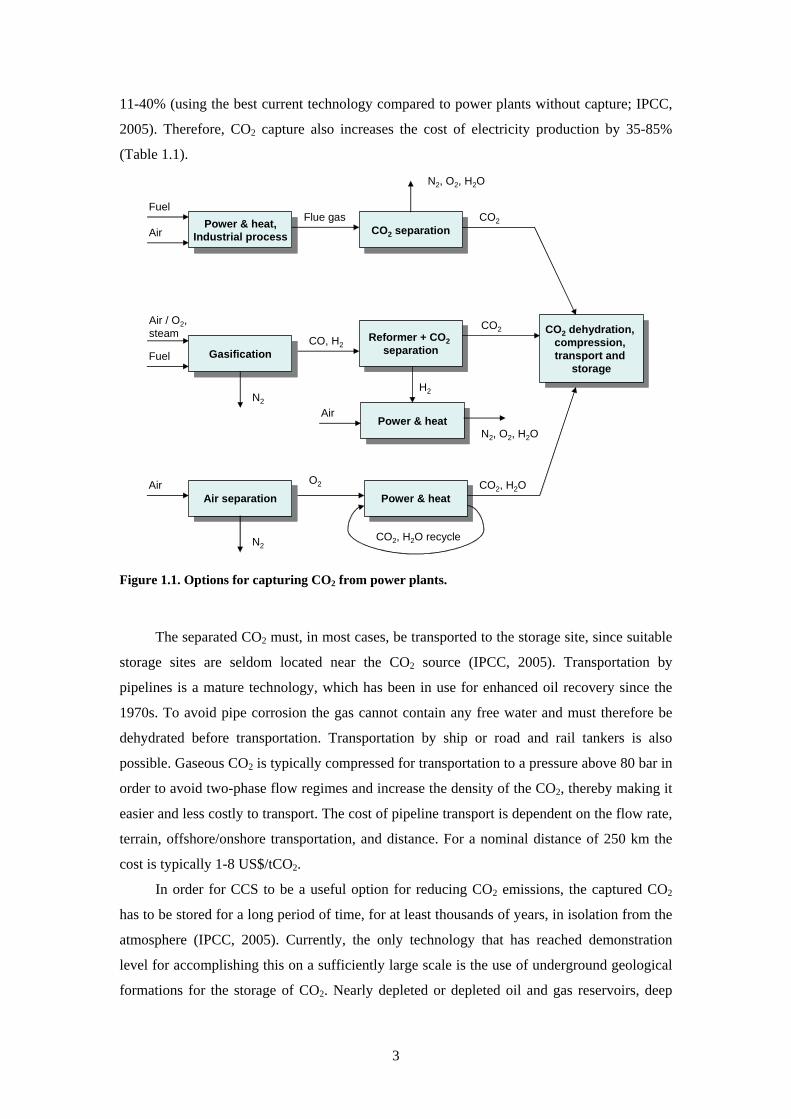
applied post-combustion pre-combustion and oxy-fuel combustion systems (Figure 11)
Post-combustion systems separate CO2 from a flue gas stream2 typically using a liquid
solvent such as monoethanolamine It is used for absorbing CO2 from part of the flue gases
from a number of existing power plants It is also in commercial use in the natural gas
processing industry Pre-combustion systems remove CO2 before combustion by employing
gasification water-shifting and CO2 separation This technology is widely applied in fertiliser
manufacturing and in hydrogen production Oxy-fuel combustion systems use oxygen instead
of air for the combustion of the primary fuel to produce a flue gas that consists mainly of
water vapour and CO2 This relatively new technology requires the production of pure oxygen
from air and results in a flue gas with high CO2 concentrations from which the water vapour is
removed by condensation
The main challenge for the development of CO2 capture technology is to reduce the
energy requirements of the capture processes The energy needed for capturing 90 of the
CO2 from a power plant increases the fuel consumption per unit of electricity produced by 2 Flue gases from power plants burning fossil fuel typically contain 3-15 vol- CO2
2
11-40 (using the best current technology compared to power plants without capture IPCC
2005) Therefore CO2 capture also increases the cost of electricity production by 35-85
(Table 11)
Power amp heatIndustrial processPower amp heat
Industrial process CO2 separationCO2 separation
Reformer + CO2separation
Reformer + CO2separation
Power amp heatPower amp heat
Power amp heatPower amp heat
GasificationGasification
CO2 dehydration compression transport and
storage
CO2 dehydration compression transport and
storage
Fuel
AirFlue gas
N2 O2 H2O
CO2
Fuel
N2
Air O2steam
CO H2
Air
H2
N2 O2 H2O
CO2
Air separationAir separation
N2
Air O2 CO2 H2O
CO2 H2O recycle
Figure 11 Options for capturing CO2 from power plants
The separated CO2 must in most cases be transported to the storage site since suitable
storage sites are seldom located near the CO2 source (IPCC 2005) Transportation by
pipelines is a mature technology which has been in use for enhanced oil recovery since the
1970s To avoid pipe corrosion the gas cannot contain any free water and must therefore be
dehydrated before transportation Transportation by ship or road and rail tankers is also
possible Gaseous CO2 is typically compressed for transportation to a pressure above 80 bar in
order to avoid two-phase flow regimes and increase the density of the CO2 thereby making it
easier and less costly to transport The cost of pipeline transport is dependent on the flow rate
terrain offshoreonshore transportation and distance For a nominal distance of 250 km the
cost is typically 1-8 US$tCO2
In order for CCS to be a useful option for reducing CO2 emissions the captured CO2
has to be stored for a long period of time for at least thousands of years in isolation from the
atmosphere (IPCC 2005) Currently the only technology that has reached demonstration
level for accomplishing this on a sufficiently large scale is the use of underground geological
formations for the storage of CO2 Nearly depleted or depleted oil and gas reservoirs deep
3
saline formations and unminable coal beds are the most promising options for the geological
storage of CO2 Suitable storage formations can occur in both onshore and offshore
sedimentary basins (natural large-scale depressions in the Earths crust that are filled with
sediments) In each case CO2 is injected in compressed form into a rock formation at depths
greater than 800 m where the CO2 is in a liquid or supercritical state because of the ambient
pressures To ensure that the CO2 remains trapped underground a well-sealed cap rock is
needed over the selected storage reservoir The geochemical trapping of CO2 (ie fixation as
carbonates) will eventually occur as CO2 reacts with the fluids and host rock in the reservoir
but this happens on a time scale of hundreds to millions of years In order to minimise the risk
of CO2 leakage the storage sites must be monitored for a very long time Currently there are
several projects running that demonstrate this technology The injection of CO2 into
geological formations involves many of the same technologies that have been developed in
the oil and gas exploration and production industry 30 Mt of CO2 is injected annually for
enhanced oil recovery (EOR) mostly in Texas USA where EOR has been used since the
early 1970s However most of this CO2 is obtained from natural CO2 reservoirs At the
moment three industrial-scale projects are storing 3-4 Mt of CO2 annually in saline aquifers
The estimated total CO2 storage capacity for geological formations worldwide is 2000-10000
Gt of CO2 while the costs of storage in saline formations and depleted oil and gas fields have
been estimated to be 05-8 US$tCO2 injected with an additional cost for monitoring3 of 01-
03 US$tCO2 (Table 11)
Another option for storing CO2 is to inject CO2 directly into the deep ocean at depths
greater than 1000 m This option is not a mature technology but has been under research for
several decades CO2 can be transported via pipelines or ships to an ocean storage site where
it is either injected directly into the ocean or deposited into a CO2 lake on the sea floor4 The
analysis of ocean observations and models both indicate that injected CO2 will be isolated
from the atmosphere for at least several hundred years and that the fraction retained tends to
be higher with deeper injection The cost of injecting CO2 into the ocean at 3000 m has been
estimated at 5-30 US$tCO2 (Table 11) However actively injecting CO2 may have harmful
effects on the ocean environment about which little is known Experiments show that adding
CO2 can harm marine organisms but it is still unclear what effects the injection of several
million tonnes of CO2 would have on ocean ecosystems
3 A scenario analysed in IEA (2007) for cost estimations however considers only 20 years of
monitoring after 30 years of injection in a saline aquifer 4 Such CO2 lakes must be situated deeper than 3 km below the ocean surface where CO2 is denser than
sea water
4
5
From Finlandrsquos perspective CCS does not provide an easy answer to reducing CO2
emissions since the Finnish bedrock is not suitable for the basin sequestration of CO2 The
offshore oil and gas fields and saline aquifers located in the North Sea and Barents Sea appear
to be the closest suitable CO2 sequestration sites The distances to these sites are
approximately 500-1000 km (Koljonen et al 2004) Currently the only known domestic
large-scale CO2 storage alternative for Finland is mineral carbonation because of the
availability of widespread deposits of the mineral needed for the carbonation process
Table 11 Cost ranges for the components of large-scale CCS systems (IPCC 2005)
CCS system components Cost range Remarks
Capture from a coal- or gas-
fired power plant
15-75 US$tCO2 net captured Net costs of captured CO2
compared to the same plant
without capture
Capture from hydrogen and
ammonia production or gas
processing
5-55 US$tCO2 net captured Applies to high-purity sources
requiring simple drying and
compression
Capture from other industrial
sources
25-115 US$tCO2 net captured Range reflects use of a number
of different technologies and
fuels
Transportation 1-8 US$tCO2 transported Per 250 km pipeline or shipping
for mass flow rates of 5
(high end) to 40 (low end)
MtCO2a
Geological storagea 05-8 US$tCO2 net injected Excluding potential revenues
from EOR or ECBM
Geological storage monitoring
and verification
01-03 US$tCO2 injected This covers pre-injection
injection and post-injection
monitoring and depends on the
regulatory requirements
Ocean storage 5-30 US$tCO2 net injected Including offshore transporta-
tion of 100-500 km excluding
monitoring and verification
Mineral carbonation 50-100 US$tCO2 net
mineralised
Range for the best case studied
Includes additional energy use
for carbonation aIn the long term there may be additional costs for remediation and liabilities
12 Mineral carbonation
CO2 could be stored in the form of solid inorganic carbonates by means of chemical
reactions Calcium and magnesium carbonates are formed in nature by a process known as the
weathering of rocks In this natural process calcium and magnesium ions are leached out of
silicate rocks by rivers and rainfall and react with CO2 forming solid calcium and magnesium
carbonates The concept of an accelerated carbonation process for the storage of CO2 is
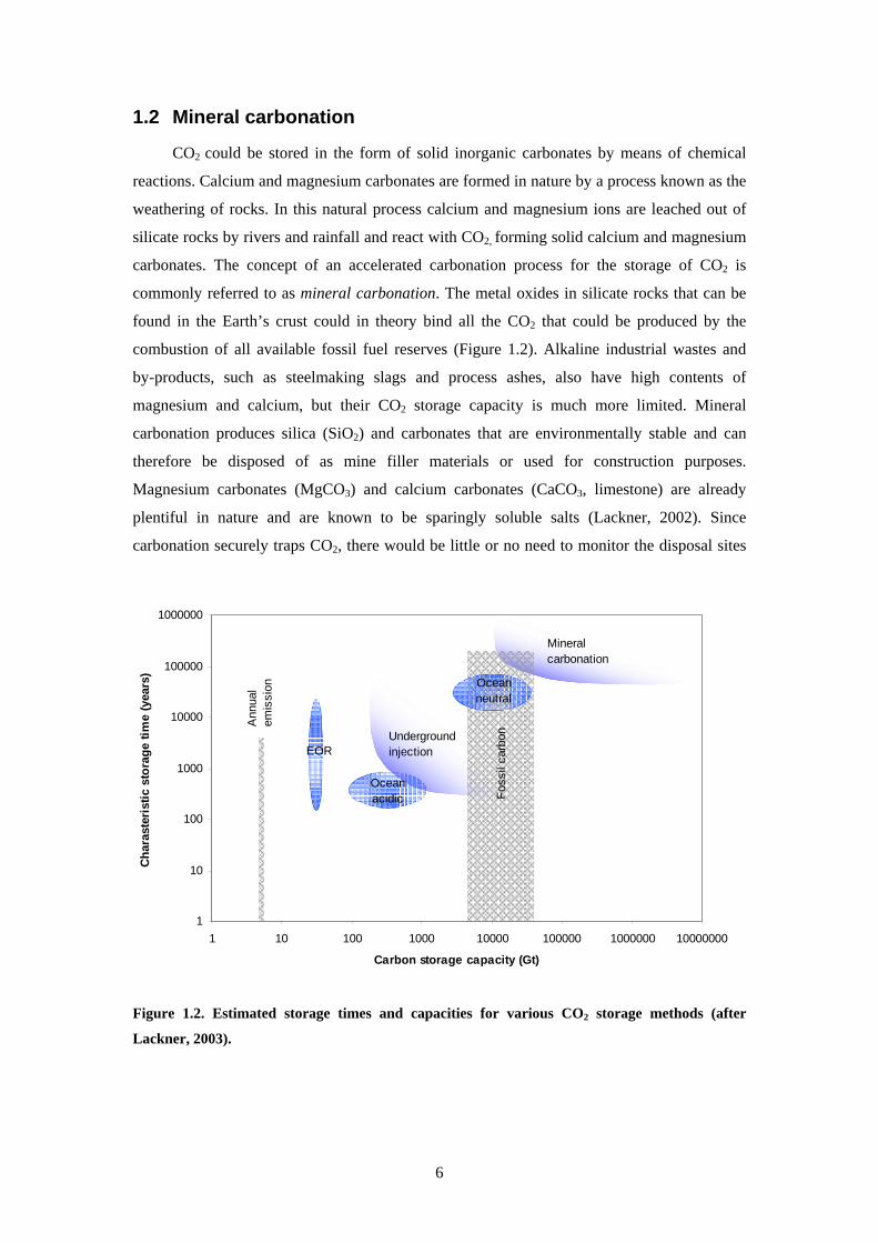
commonly referred to as mineral carbonation The metal oxides in silicate rocks that can be
found in the Earthrsquos crust could in theory bind all the CO2 that could be produced by the
combustion of all available fossil fuel reserves (Figure 12) Alkaline industrial wastes and
by-products such as steelmaking slags and process ashes also have high contents of
magnesium and calcium but their CO2 storage capacity is much more limited Mineral
carbonation produces silica (SiO2) and carbonates that are environmentally stable and can
therefore be disposed of as mine filler materials or used for construction purposes
Magnesium carbonates (MgCO3) and calcium carbonates (CaCO3 limestone) are already
plentiful in nature and are known to be sparingly soluble salts (Lackner 2002) Since
carbonation securely traps CO2 there would be little or no need to monitor the disposal sites
1
10
100
1000
10000
100000
1000000
1 10 100 1000 10000 100000 1000000 10000000
Carbon storage capacity (Gt)
Cha
rast
eris
tic s
tora
ge ti
me
(yea
rs)
Ann
ual
emis
sion
EOR
Foss
il ca
rbonUnderground
injection
Mineralcarbonation
Oceanneutral
Oceanacidic
Figure 12 Estimated storage times and capacities for various CO2 storage methods (after
Lackner 2003)
6
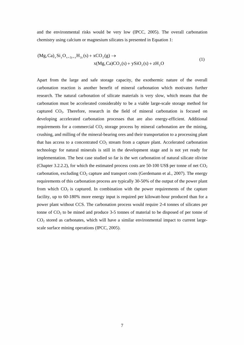
and the environmental risks would be very low (IPCC 2005) The overall carbonation
chemistry using calcium or magnesium silicates is presented in Equation 1
OzH(s)ySiO(s)Ca)COx(Mg
(g)xCO(s)HOSiCa)(Mg
223
22zz2yxyx
++
rarr+++ (1)
Apart from the large and safe storage capacity the exothermic nature of the overall
carbonation reaction is another benefit of mineral carbonation which motivates further
research The natural carbonation of silicate materials is very slow which means that the
carbonation must be accelerated considerably to be a viable large-scale storage method for
captured CO2 Therefore research in the field of mineral carbonation is focused on
developing accelerated carbonation processes that are also energy-efficient Additional
requirements for a commercial CO2 storage process by mineral carbonation are the mining
crushing and milling of the mineral-bearing ores and their transportation to a processing plant
that has access to a concentrated CO2 stream from a capture plant Accelerated carbonation
technology for natural minerals is still in the development stage and is not yet ready for
implementation The best case studied so far is the wet carbonation of natural silicate olivine
(Chapter 3222) for which the estimated process costs are 50-100 US$ per tonne of net CO2
carbonation excluding CO2 capture and transport costs (Gerdemann et al 2007) The energy
requirements of this carbonation process are typically 30-50 of the output of the power plant
from which CO2 is captured In combination with the power requirements of the capture
facility up to 60-180 more energy input is required per kilowatt-hour produced than for a
power plant without CCS The carbonation process would require 2-4 tonnes of silicates per
tonne of CO2 to be mined and produce 3-5 tonnes of material to be disposed of per tonne of
CO2 stored as carbonates which will have a similar environmental impact to current large-
scale surface mining operations (IPCC 2005)
7
2 Objective of this thesis The main challenge for using mineral carbonation for CO2 sequestration is to develop an
economically feasible process To achieve this economic and rapid methods for extracting
reactive magnesium or calcium compounds (such as oxides hydroxides or base ions) from
the rock and for carbonating these must be developed An implemented carbonation process
for CO2 sequestration would be on the scale of an average-sized open mining facility because
of the large amounts of minerals required Therefore besides providing rapid conversion the
carbonation process must also convert as much as possible of the minerals to carbonates in
order for the environmental impact to be minimal
An important aspect of mineral carbonation is the end-use or disposal of the carbonate
product Using mineral carbonation for sequestering CO2 the material amounts of carbonates
silica and other compounds (depending on the raw material used) from such a process would
be huge sequestering 1 Mt of CO2 produces 23 Mt of CaCO3 or 19 Mt of MgCO3 (assuming
a conversion efficiency of 100) with various amounts of silica and other by-products
depending on the raw material used Therefore it is very important to be able to utilise these
products as much as possible Although the end-products of a carbonation process for CO2
storage would eventually exceed the market demand the possibility of selling them could
help to introduce a technology infrastructure for mineral carbonation and develop it into a
feasible CO2 storage technology
The technology for producing synthetic calcium carbonate from limestone is known and
used on an industrial scale but the carbonation of silicate minerals requires other processes
than those used for limestone carbonation While the direct carbonation of magnesium
silicates and calcium silicates has been comprehensively studied most of these processes
produce an aqueous slurry of carbonates unreacted silicates silica and other by-products
from which it is difficult to separate the individual components (OrsquoConnor et al 2005
Huijgen et al 2006) Indirect (or multi-step) processes such as those suggested by Lackner et
al (1995) and Kakizawa et al (2001) allow for the separation of silica and other by-products
such as metals and minerals before the carbonation step An indirect process is therefore a
better alternative for producing separate streams of carbonates and other materials for further
recovery The present work shows that industrial wastes and by-products can be converted
into more valuable products using indirect carbonation processes However very little in the
way of experimental data on these processes can be found in the literature The relatively high
price of precipitated calcium carbonate (over ten times that of raw limestone or steelmaking
slag products) could justify the development of a carbonation process with high running costs
8
However the purity and crystal structure of the synthetic carbonate and other products of
such a process determine their value
The objective of this thesis was to study the possibility and potential of producing
relatively pure calcium and magnesium carbonates from silicate materials for the long-term
storage of CO2 using indirect processes The research tasks for achieving this were
i Evaluate the CO2 emission reduction potential by producing precipitated calcium
carbonate from calcium silicates instead of limestone (Paper I)
ii Study the possibility of producing calcium carbonates from steelmaking slags for
the reduction of CO2 emissions by experimental and theoretical research (Papers
II-III)
iii Study the possibility of producing magnesium carbonates from serpentinite for
the sequestration of CO2 by experimental and theoretical research (Papers IV-
VI)
iv Evaluate the stability of synthetic magnesium and calcium carbonates as a
medium for CO2 storage (Papers VI-VII)
Processes for calcium silicate carbonation suggested in the literature were studied by
process modelling and their energy use and net potential for CO2 fixation were evaluated An
acetic acid process appeared to be the most promising of the systems studied for the
carbonation of calcium silicates Since natural calcium silicate mineral resources were found
to be scarce the use of steelmaking slags for carbonate production was investigated by means
of experiments and theoretical calculations The large resources of magnesium silicates
justified the systematic development of an indirect process for converting magnesium silicates
into magnesium carbonates Finally the stability of magnesium carbonate and calcium
carbonate as a medium for CO2 storage was evaluated
9
3 Literature review The purpose of this literature review was
bull To select raw materials potentially suitable for carbonation and readily available
in Finland
bull To review the most comprehensively studied carbonation routes proposed in the
literature as well as the processes that are relevant for this work
bull To discuss potential markets and uses for the carbonates produced
31 Suitable raw materials
In order to provide for significant storage of CO2 large amounts of raw materials are
required as feedstock for carbonation Therefore the raw materials used for carbonation must
be abundant and cheap
From a chemical elements perspective both alkali (eg Na K etc) and alkaline earth
(eg Ca Mg) metals can be carbonated (Huijgen and Comans 2003 2005) However alkali
metals are unsuitable for the long-term storage of CO2 since alkali (bi)carbonates are soluble
in water which could release CO2 back into the atmosphere Additionally a number of other
metals (eg Mn Fe Co Ni Cu and Zn) could potentially be carbonated but most of these
elements are either too rare or too valuable to be used for the sequestration of CO2 Of the
alkaline earth metals magnesium and calcium are by far the most common in nature The
Earthrsquos crust consists of roughly 2 mol- magnesium and 2 mol- calcium primarily bound
as carbonates and silicate minerals (Goff and Lackner 1998 Brownlow 1996)
In order to minimise the amount of raw material needed materials with high
concentrations of calcium and magnesium should be favoured while materials already
containing significant concentrations of carbonates should be avoided From this perspective
magnesium and calcium oxides or hydroxides would be ideal materials but these are rare in
nature Calcium silicates and magnesium silicates are particularly suitable for carbonation
since these materials are abundant in the Earthrsquos crust The storage capacity of silicate
minerals has been estimated at 10000-10000000 Gt of carbon (Figure 12) which exceeds
the amount of carbon in known fossil fuel resources Although calcium silicates tend to be
more reactive for carbonation than magnesium silicates calcium silicates with high
concentrations of calcium are relatively rare (Lackner 2002) The Finnish bedrock consists
locally of rock types that contain an abundance of Mg and Ca silicates such as serpentine
pyroxenes amphiboles and talc which could be suitable for carbonation (Teir et al 2006a)
Several industrial residues and by-products such as iron and steel slags various process
10
ashes and cement-based materials can have high concentrations of calcium and magnesium
Although the amounts of by-products and residues are much smaller than natural resources
by-products and residues are readily available continuously produced and tend to be more
reactive than natural minerals
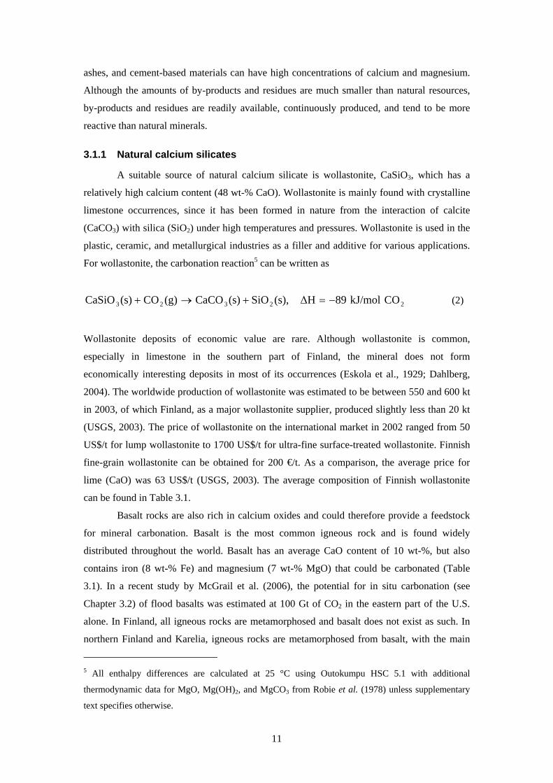
311 Natural calcium silicates
A suitable source of natural calcium silicate is wollastonite CaSiO3 which has a
relatively high calcium content (48 wt- CaO) Wollastonite is mainly found with crystalline
limestone occurrences since it has been formed in nature from the interaction of calcite
(CaCO3) with silica (SiO2) under high temperatures and pressures Wollastonite is used in the
plastic ceramic and metallurgical industries as a filler and additive for various applications
For wollastonite the carbonation reaction5 can be written as
22323 COkJmol89∆H(s)SiO(s)CaCO(g)CO(s)CaSiO minus=+rarr+ (2)
Wollastonite deposits of economic value are rare Although wollastonite is common
especially in limestone in the southern part of Finland the mineral does not form
economically interesting deposits in most of its occurrences (Eskola et al 1929 Dahlberg
2004) The worldwide production of wollastonite was estimated to be between 550 and 600 kt
in 2003 of which Finland as a major wollastonite supplier produced slightly less than 20 kt
(USGS 2003) The price of wollastonite on the international market in 2002 ranged from 50
US$t for lump wollastonite to 1700 US$t for ultra-fine surface-treated wollastonite Finnish
fine-grain wollastonite can be obtained for 200 eurot As a comparison the average price for
lime (CaO) was 63 US$t (USGS 2003) The average composition of Finnish wollastonite
can be found in Table 31
Basalt rocks are also rich in calcium oxides and could therefore provide a feedstock
for mineral carbonation Basalt is the most common igneous rock and is found widely
distributed throughout the world Basalt has an average CaO content of 10 wt- but also
contains iron (8 wt- Fe) and magnesium (7 wt- MgO) that could be carbonated (Table
31) In a recent study by McGrail et al (2006) the potential for in situ carbonation (see
Chapter 32) of flood basalts was estimated at 100 Gt of CO2 in the eastern part of the US
alone In Finland all igneous rocks are metamorphosed and basalt does not exist as such In
northern Finland and Karelia igneous rocks are metamorphosed from basalt with the main
5 All enthalpy differences are calculated at 25 degC using Outokumpu HSC 51 with additional
thermodynamic data for MgO Mg(OH)2 and MgCO3 from Robie et al (1978) unless supplementary
text specifies otherwise
11
12
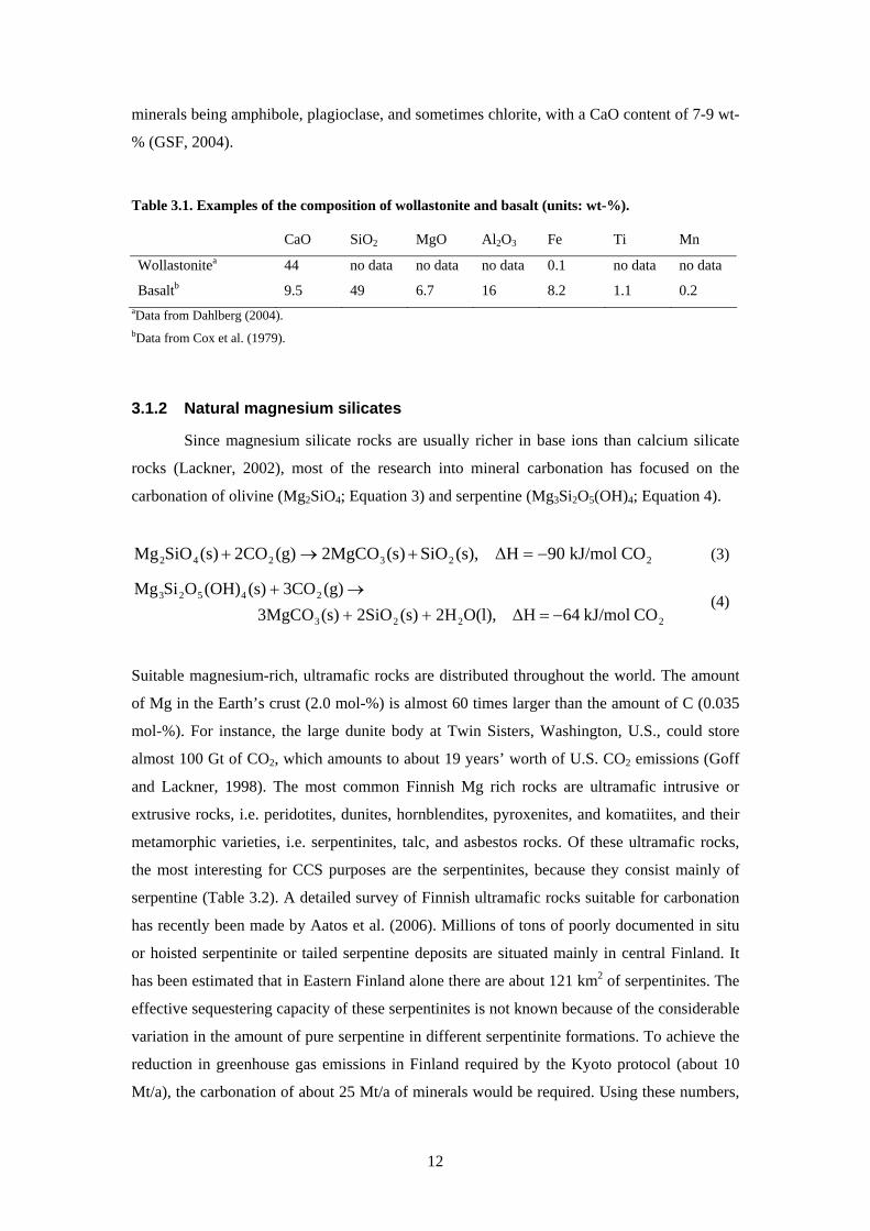
minerals being amphibole plagioclase and sometimes chlorite with a CaO content of 7-9 wt-
(GSF 2004)
Table 31 Examples of the composition of wollastonite and basalt (units wt-)
CaO SiO2 MgO Al2O3 Fe Ti Mn
Wollastonitea 44 no data no data no data 01 no data no data
Basaltb 95 49 67 16 82 11 02 aData from Dahlberg (2004) bData from Cox et al (1979)
312 Natural magnesium silicates
Since magnesium silicate rocks are usually richer in base ions than calcium silicate
rocks (Lackner 2002) most of the research into mineral carbonation has focused on the
carbonation of olivine (Mg2SiO4 Equation 3) and serpentine (Mg3Si2O5(OH)4 Equation 4)
223242 COkJmol90∆H(s)SiO)s(2MgCO(g)2CO(s)SiOMg minus=+rarr+ (3)
2223
24523
COkJmol64∆HO(l)2H(s)2SiO(s)3MgCO(g)3CO(s)(OH)OSiMg
minus=++rarr+
(4)
Suitable magnesium-rich ultramafic rocks are distributed throughout the world The amount
of Mg in the Earthrsquos crust (20 mol-) is almost 60 times larger than the amount of C (0035
mol-) For instance the large dunite body at Twin Sisters Washington US could store
almost 100 Gt of CO2 which amounts to about 19 yearsrsquo worth of US CO2 emissions (Goff
and Lackner 1998) The most common Finnish Mg rich rocks are ultramafic intrusive or
extrusive rocks ie peridotites dunites hornblendites pyroxenites and komatiites and their
metamorphic varieties ie serpentinites talc and asbestos rocks Of these ultramafic rocks
the most interesting for CCS purposes are the serpentinites because they consist mainly of
serpentine (Table 32) A detailed survey of Finnish ultramafic rocks suitable for carbonation
has recently been made by Aatos et al (2006) Millions of tons of poorly documented in situ
or hoisted serpentinite or tailed serpentine deposits are situated mainly in central Finland It
has been estimated that in Eastern Finland alone there are about 121 km2 of serpentinites The
effective sequestering capacity of these serpentinites is not known because of the considerable
variation in the amount of pure serpentine in different serpentinite formations To achieve the
reduction in greenhouse gas emissions in Finland required by the Kyoto protocol (about 10
Mta) the carbonation of about 25 Mta of minerals would be required Using these numbers
the serpentinites of the Outokumpu-Kainuu ultramafic rock belt could theoretically be
sufficient for 200-300 years of CCS processing (Teir et al 2006a Aatos et al 2006)
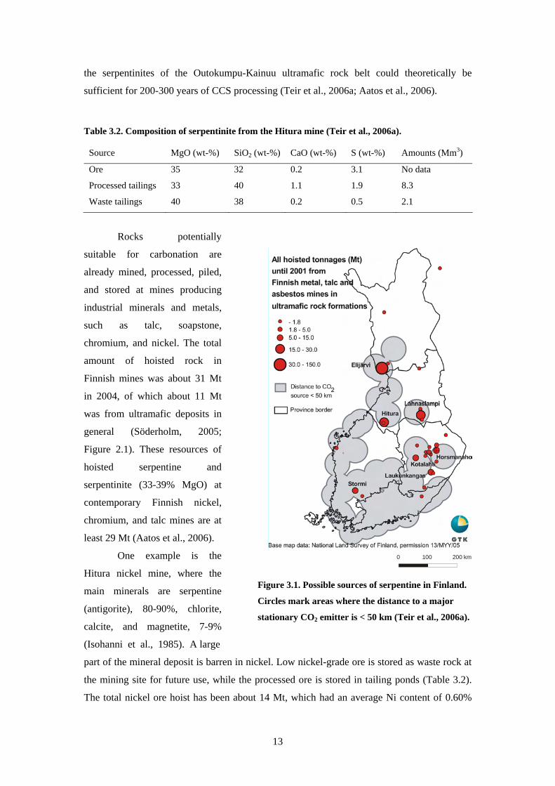
Table 32 Composition of serpentinite from the Hitura mine (Teir et al 2006a)
Source MgO (wt-) SiO2 (wt-) CaO (wt-) S (wt-) Amounts (Mm3)
Ore 35 32 02 31 No data
Processed tailings 33 40 11 19 83
Waste tailings 40 38 02 05 21
Rocks potentially
suitable for carbonation are
already mined processed piled
and stored at mines producing
industrial minerals and metals
such as talc soapstone
chromium and nickel The total
amount of hoisted rock in
Finnish mines was about 31 Mt
in 2004 of which about 11 Mt
was from ultramafic deposits in
general (Soumlderholm 2005
Figure 21) These resources of
hoisted serpentine and
serpentinite (33-39 MgO) at
contemporary Finnish nickel
chromium and talc mines are at
least 29 Mt (Aatos et al 2006)
One example is the
Hitura nickel mine where the
main minerals are serpentine
(antigorite) 80-90 chlorite
calcite and magnetite 7-9
(Isohanni et al 1985) A large
0 100 200 km
Figure 31 Possible sources of serpentine in Finland
Circles mark areas where the distance to a major
stationary CO2 emitter is lt 50 km (Teir et al 2006a)
part of the mineral deposit is barren in nickel Low nickel-grade ore is stored as waste rock at
the mining site for future use while the processed ore is stored in tailing ponds (Table 32)
The total nickel ore hoist has been about 14 Mt which had an average Ni content of 060
13
(Teir et al 2006b) If the hoisted ore has an average MgO content of 34 wt- 53 Mt of CO2
could be stored using the presently hoisted ore alone
313 Alkaline solid waste materials
While most research into mineral CO2 sequestration focuses on the carbonation of
natural silicate minerals there have also been considerable and successful efforts to carbonate
solid alkaline waste materials Many various types of solid alkaline waste materials are
available in large amounts and are generally rich in calcium Wastes that have been
considered for carbonation include ash from coal-fired power plants (CaO content up to 65
wt-) bottom ash (~20 wt- CaO) and fly ash (~35 wt- CaO) from municipal solid waste
incinerators de-inking ash from paper recycling (~35 wt- CaO) steelmaking slag (~30-60
wt- CaO and MgO) and waste cement (Fernaacutendez Bertos et al 2004 Johnson 2000
Huijgen et al 2005 Iizuka et al 2004 Yogo et al 2004 Uibu et al 2005) Most research
seems to have concentrated on carbonation as a means for immobilising toxic elements and
heavy metals as well as improving the structural durability of wastes and by-products to
render them better suited for landfill or construction purposes However carbonation has also
been found to increase the leaching of certain elements such as vanadium in steel slag
(Huijgen and Comans 2006)
Finland has a large steel industry which is very energy-intensive and has high CO2
emissions The largest single source of anthropogenic CO2 emissions in Finland accounting
for 47 Mt of CO2a (Ruukki 2005) is the steel plant at Raahe Carbonating the steelmaking
slags which are by-products of the steelmaking processes could be an interesting option for
reducing the CO2 emissions from the steel plant
3131 Iron and steel slag
Iron and steel slags (in short steelmaking slags) are non-metallic by-products of
many steelmaking operations and consist principally of calcium magnesium and aluminium
silicates as well as iron and manganese The proportions vary with the conditions and the
feedstock for the particular iron or steel production process where the slag is generated
Calcium compounds account for the largest constituents with a CaO content of 40-52
(Stolaroff et al 2005)
Crude or pig iron is produced in a blast furnace where lime or limestone is used to
remove oxygen and other impurities from iron and adjust the viscosity of the smelts
Limestone decomposes at high temperatures (see Chapter 325 Equation 36) and combines
with impurities such as silicon dioxide (SiO2) to form a liquid calcium silicate melt called
iron or blast furnace slag which can be removed from the blast furnace separately from iron
14
( ) ( )y2x2 SiOCaOySiOxCaO sdotrarr+ (5)
After the blast furnace the crude iron produced is transported to a steel converter usually a
basic oxygen furnace (BOF) where the residual carbon content of the iron is reduced from 4
wt- to 05 wt- Steel furnaces particularly electric arc furnaces (EAF) may also use scrap
metals as feedstock instead of pig iron Impurities and carbon are also removed in the steel
furnace by slag formation similarly to that in a blast furnace Stainless steel grades (gt 10 wt-
Cr) are usually produced in an induction or electric arc furnace sometimes under vacuum
To refine stainless steel a so-called argon-oxygen decarburisation (AOD) process is used
The physical attributes of the solidified slags depend mainly on the cooling technique
used air-cooled granulated (water-cooled) and pelletised (or expanded) slags are the three
main types The cooling method also largely determines the uses for the slag After cooling
the slag may be further processed (mainly by crushing) prior to being sold (USGS 2003)
Steel slags are highly variable with respect to their composition even those from the same
plant and furnace Apart from the feedstock impurities slags (especially steel converter slags)
may also contain significant amounts of entrained free metal The amount of slag produced is
largely related to the overall chemistry of the raw materials (Ahmed 1993) The chemical
composition of the slag is also variable and depends on both the chemical composition of the
feed and the type of furnace used Slags are widely used for road construction purposes as
asphalt and cement aggregate Slags have very low prices (eg blast furnace slag from Ruukki
can be bought for 10 eurot excluding shipping costs) in comparison to steel products and are
usually considered to be unwanted by-products of the steel production process
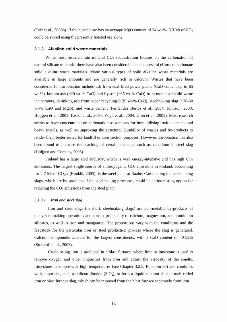
Table 33 Production of steel mills in Finland in 2004 (units kta)
Steel mill Company
Steel
production
CO2e
emissions Iron slag Steel slag
Ferrochrome
slag
Raahea Ruukki 2719 4740 571 302 -
Koverharb Ovako 618 890 96 62 -
Tornioc Outokumpu 1200 670 - 47 309
Imatrad Ovako 243 58 36f - aData from Ruukki (2005) bData supplied by Magnus Gottberg Ovako cData from Outokumpu (2005) dData supplied by Helena Kumpulainen Ovako eFinlandrsquos total anthropogenic CO2 emissions in 2004 were 69 Mt (excluding land use land use change and
forestry STAT 2007) fNumber represents the total steelmaking slag production of the mill
15
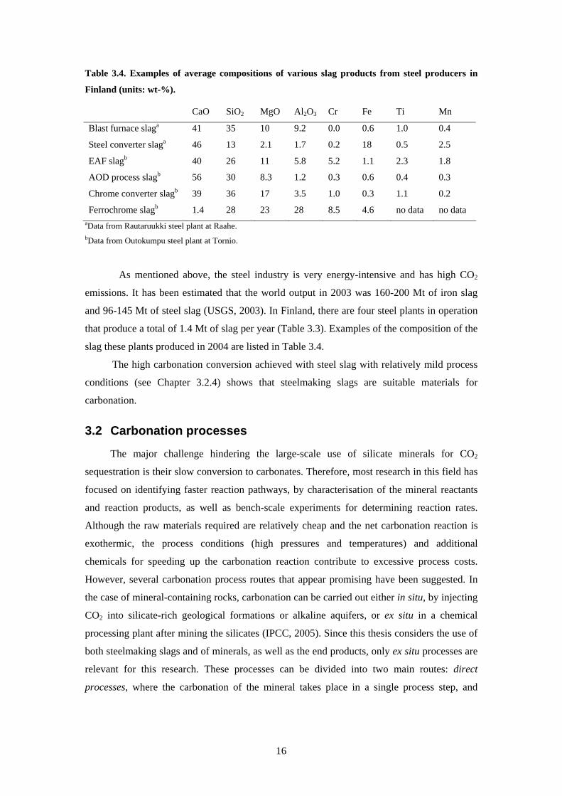
Table 34 Examples of average compositions of various slag products from steel producers in
Finland (units wt-)
CaO SiO2 MgO Al2O3 Cr Fe Ti Mn
Blast furnace slaga 41 35 10 92 00 06 10 04
Steel converter slaga 46 13 21 17 02 18 05 25
EAF slagb 40 26 11 58 52 11 23 18
AOD process slagb 56 30 83 12 03 06 04 03
Chrome converter slagb 39 36 17 35 10 03 11 02
Ferrochrome slagb 14 28 23 28 85 46 no data no data aData from Rautaruukki steel plant at Raahe bData from Outokumpu steel plant at Tornio
As mentioned above the steel industry is very energy-intensive and has high CO2
emissions It has been estimated that the world output in 2003 was 160-200 Mt of iron slag
and 96-145 Mt of steel slag (USGS 2003) In Finland there are four steel plants in operation
that produce a total of 14 Mt of slag per year (Table 33) Examples of the composition of the
slag these plants produced in 2004 are listed in Table 34
The high carbonation conversion achieved with steel slag with relatively mild process
conditions (see Chapter 324) shows that steelmaking slags are suitable materials for
carbonation
32 Carbonation processes
The major challenge hindering the large-scale use of silicate minerals for CO2
sequestration is their slow conversion to carbonates Therefore most research in this field has
focused on identifying faster reaction pathways by characterisation of the mineral reactants
and reaction products as well as bench-scale experiments for determining reaction rates
Although the raw materials required are relatively cheap and the net carbonation reaction is
exothermic the process conditions (high pressures and temperatures) and additional
chemicals for speeding up the carbonation reaction contribute to excessive process costs
However several carbonation process routes that appear promising have been suggested In
the case of mineral-containing rocks carbonation can be carried out either in situ by injecting
CO2 into silicate-rich geological formations or alkaline aquifers or ex situ in a chemical
processing plant after mining the silicates (IPCC 2005) Since this thesis considers the use of
both steelmaking slags and of minerals as well as the end products only ex situ processes are
relevant for this research These processes can be divided into two main routes direct
processes where the carbonation of the mineral takes place in a single process step and
16
indirect processes where calcium or magnesium is first extracted from the mineral and
subsequently carbonated
321 Weathering of rocks
The idea of CO2 disposal by carbonate formation comes from the natural silicate
weathering process which binds about 100 Mt of carbon per year (Seifritz 1990)6
2
232
223
COkJmol63∆H(s)SiO(aq)2HCO(aq)CaO(l)H(aq)2CO(s)CaSiO
minus=++rarr++ minus+
(6)
Rainfall is slightly acidic by nature because atmospheric carbon dioxide dissolves in
rainwater producing weak carbonic acid Calcium is therefore leached from calcium silicate-
containing rocks by rainwater containing dissolved CO2 (Brownlow 1996) Magnesium
silicates (olivine and serpentine) are similarly dissolved by rainwater
2
232
2242
COkJmol280∆H(s)SiO(aq)4HCO(aq)2MgO(l)2H(aq)4CO(s)SiOMg
minus=++rarr++ minus+
(7)
2232
224523
COkJmol349∆H(s)2SiO(aq)6HCO(aq)3Mg
O(l)H(aq)6CO(s)(OH)OSiMg
minus=++
rarr++minus+
(8)
Rainwater carries the leached calcium and magnesium to rivers and subsequently to the
ocean where calcium and magnesium precipitates and forms solid calcium and magnesium
carbonates (M2+ represents either Ca2+ or Mg2+)
(s)COM(aq)CO(aq)M -23
223
2 +minus+ rarr+ (9)
The precipitation and dissolution of carbonates controls the pH in the oceans naturally
according to the equilibrium involving CO2 and calcium carbonate (Brownlow 1996)
(aq)CO(g)CO 22 harr (10)
(aq)2H(aq)CO(aq)H(aq)HCO
(aq)COH(aq)COO(l)H233
3222+minus+minus +harr+
harrharr+ (11)
6 All enthalpy differences are calculated at 25 degC using Outokumpu HSC 51 with additional
thermodynamic data for MgCO3 from Robie et al (1978) unless supplementary text specifies
otherwise
17
(aq)2HCO(aq)M(aq)COH(s)COM 32
32-2
32 minus++ +harr+ (12)
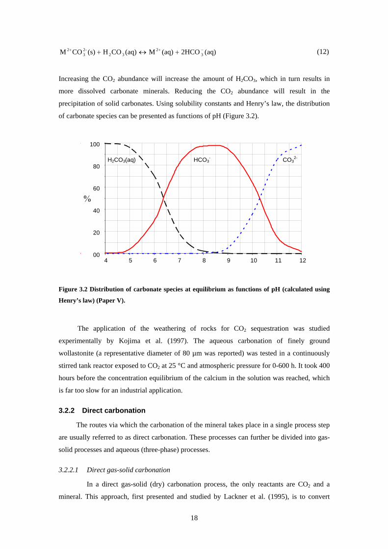
Increasing the CO2 abundance will increase the amount of H2CO3 which in turn results in
more dissolved carbonate minerals Reducing the CO2 abundance will result in the
precipitation of solid carbonates Using solubility constants and Henryrsquos law the distribution
of carbonate species can be presented as functions of pH (Figure 32)
00
20
40
60
80
100
4 5 6 7 8 9 10 11 12
H2CO3(aq) HCO3-
CO32-
Figure 32 Distribution of carbonate species at equilibrium as functions of pH (calculated using
Henryrsquos law) (Paper V)
The application of the weathering of rocks for CO2 sequestration was studied
experimentally by Kojima et al (1997) The aqueous carbonation of finely ground
wollastonite (a representative diameter of 80 microm was reported) was tested in a continuously
stirred tank reactor exposed to CO2 at 25 degC and atmospheric pressure for 0-600 h It took 400
hours before the concentration equilibrium of the calcium in the solution was reached which
is far too slow for an industrial application
322 Direct carbonation
The routes via which the carbonation of the mineral takes place in a single process step
are usually referred to as direct carbonation These processes can further be divided into gas-
solid processes and aqueous (three-phase) processes
3221 Direct gas-solid carbonation
In a direct gas-solid (dry) carbonation process the only reactants are CO2 and a
mineral This approach first presented and studied by Lackner et al (1995) is to convert
18
silicate minerals directly to carbonates (according to the reactions presented in Equations 2-4)
using gaseous or supercritical CO2 The advantages of the direct carbonate approach are its
simplicity and the possibility of recovering heat at high temperatures The high temperature
heat that is generated could possibly be used for process requirements or even electricity
generation (Zevenhoven and Kavaliauskaite 2004) The reaction proceeds very slowly at
room temperature but the rate can be accelerated by increasing the temperature However
above a certain temperature the reaction equilibrium shifts and favours free CO2 instead of
carbonates This temperature limit can be raised by increasing the CO2 pressure The highest
reported conversion by direct carbonation appears to be 25 of the stoichiometric maximum
which was achieved by exposing serpentine particles of 100 microm to a CO2 pressure of 340 bars
and a temperature of 500 degC for 2 h (Lackner et al 1997a)
3222 Direct aqueous carbonation
The most comprehensively studied carbonation process is the direct aqueous
carbonation of magnesium silicates (OrsquoConnor et al 2000 Gerdemann et al 2007) In this
process a slurry of water and pre-treated olivine (Equations 13 and 14) or serpentine
(Equation 15) is reacted with pressurised carbon dioxide to produce magnesium carbonate
Although the conversion chemistry involves three steps it takes place in a single reactor
Carbon dioxide is dissolved in water to form carbonic acid (H2CO3) which dissociates to
hydrogen cations (H+) and bicarbonate anions (HCO3-) (Equations 10 and 11) The hydrogen
cations reacts with the mineral liberating magnesium cations (Mg2+) which react with the
bicarbonate to form solid carbonate and silicic acid (which in turn becomes silica and water)
According to OrsquoConnor et al (2005) the same process could be used for carbonating Ca- and
Fe(II)-rich silicates as well (Equations 16 and 17)
234523
2242
COkJmol157∆H(s)MgCO(s)(OH)OSiMgO(l)2H(g)CO(s)SiO2Mg
minus=+rarr++
(13)
2443
2242
COkJmol80∆H(aq)SiOH(s)2MgCOO(l)2H(g)2CO(s)SiOMg
minus=+rarr++
(14)
2443
224523
COkJmol37∆H(aq)SiO2H(s)3MgCOO(l)2H(g)3CO(s)(OH)OSiMg
minus=+rarr++
(15)
2443
2242
COkJmol57∆H(aq)SiOH(s)2FeCOO(l)2H(g)2CO(s)SiOFe
minus=+rarr++
(16)
2443
223
COkJmol75∆H(aq)SiOH(s)CaCOO(l)2H(g)CO(s)CaSiO
minus=+rarr++
(17)
19
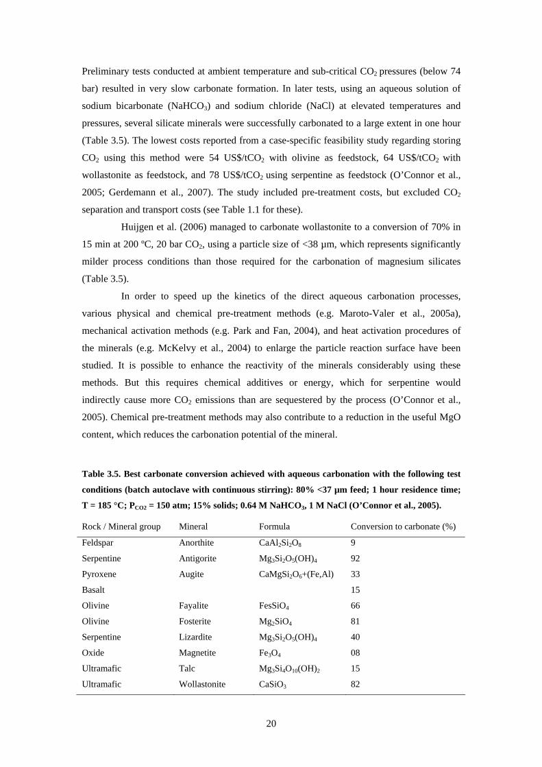
Preliminary tests conducted at ambient temperature and sub-critical CO2 pressures (below 74
bar) resulted in very slow carbonate formation In later tests using an aqueous solution of
sodium bicarbonate (NaHCO3) and sodium chloride (NaCl) at elevated temperatures and
pressures several silicate minerals were successfully carbonated to a large extent in one hour
(Table 35) The lowest costs reported from a case-specific feasibility study regarding storing
CO2 using this method were 54 US$tCO2 with olivine as feedstock 64 US$tCO2 with
wollastonite as feedstock and 78 US$tCO2 using serpentine as feedstock (OrsquoConnor et al
2005 Gerdemann et al 2007) The study included pre-treatment costs but excluded CO2
separation and transport costs (see Table 11 for these)
Huijgen et al (2006) managed to carbonate wollastonite to a conversion of 70 in
15 min at 200 ordmC 20 bar CO2 using a particle size of lt38 microm which represents significantly
milder process conditions than those required for the carbonation of magnesium silicates
(Table 35)
In order to speed up the kinetics of the direct aqueous carbonation processes
various physical and chemical pre-treatment methods (eg Maroto-Valer et al 2005a)
mechanical activation methods (eg Park and Fan 2004) and heat activation procedures of
the minerals (eg McKelvy et al 2004) to enlarge the particle reaction surface have been
studied It is possible to enhance the reactivity of the minerals considerably using these
methods But this requires chemical additives or energy which for serpentine would
indirectly cause more CO2 emissions than are sequestered by the process (OrsquoConnor et al
2005) Chemical pre-treatment methods may also contribute to a reduction in the useful MgO
content which reduces the carbonation potential of the mineral
Table 35 Best carbonate conversion achieved with aqueous carbonation with the following test
conditions (batch autoclave with continuous stirring) 80 lt37 microm feed 1 hour residence time
T = 185 degC P = 150 atm 15 solids 064 M NaHCO 1 M NaCCO2 3 l (OrsquoConnor et al 2005)
Rock Mineral group Mineral Formula Conversion to carbonate ()
Feldspar Anorthite CaAl Si O2 2 8 9
Serpentine Antigorite Mg Si O (OH)3 2 5 4 92
Pyroxene Augite CaMgSi O +(FeAl)2 6 33
Basalt 15
Olivine Fayalite FesSiO4 66
Olivine Fosterite Mg SiO2 4 81
Serpentine Lizardite Mg Si O (OH)3 2 5 4 40
Oxide Magnetite Fe O3 4 08
Ultramafic Talc Mg Si O (OH)3 4 10 2 15
Ultramafic Wollastonite CaSiO3 82
20
323 Indirect carbonation
In indirect carbonation processes a reactive magnesium or calcium compound is first
extracted from the mineral after which the intermediate magnesiumcalcium products are
carbonated Most of these processes usually provide a faster carbonation route than direct
processes but demand additional energy or chemicals
3231 Indirect gas-solid carbonation
In order to improve the conversion rate the mineral could first be converted into an
oxide or hydroxide (see Chapter 3232) and subsequently carbonated
22322 COkJmol81∆HO(lg)H(s)MgCO(g)CO(s)Mg(OH) minus=+rarr+ (18)
232 COkJmol118∆H(s)MgCO(g)COMgO(s) minus=rarr+ (19)
22322 COkJmol113∆HO(lg)H(s)CaCO(g)CO(s)Ca(OH) minus=+rarr+ (20)
232 COkJmol178∆H(s)CaCO(g)COCaO(s) minus=rarr+ (21)
The direct gas-solid carbonation of calciummagnesium oxideshydroxides proceeds much
faster than the gas-solid carbonation of calciummagnesium silicates although a high
temperature and CO2 pressure are required 100 conversion of magnesium hydroxide
Mg(OH)2 was achieved in less than 2 h using a CO2 pressure of 340 bar and a temperature of
500degC (Lackner et al 1997b) It has been found that magnesium carbonate builds up on the
particle surface and forms a kinetic barrier (Butt et al 1996) Experiments with the gas-solid
carbonation of Mg(OH)2 in a fluidised bed reactor indicated that the carbonate build-up on the
particle could be removed by promoting attrition and abrasion (Teir et al 2004) Using a
pressurised thermogravimetric analyser as a reactor Mg(OH)2 (75-125 microm) has been
carbonated to conversion levels of the order 40-60 in 6 h at 540 degC and 45 bar total pressure
(99 CO21 H2O) (Zevenhoven et al 2006a) In these experiments Mg(OH)2 also seemed
to carbonate faster than MgO (Zevenhoven and Teir 2004) By grinding Mg(OH)2 to a
particle size of 01 microm 90 conversion has been achieved at 565 degC and 53 bar in 30 minutes
(Butt et al 1998) which is fast enough for a feasible process
However magnesiumcalcium oxideshydroxides are rare in nature and would have
to be produced from calciummagnesium silicates Zevenhoven et al (2006c) suggested a
staged gas-solid process for the carbonation of serpentine The process involves the extraction
of reactive magnesium as magnesium oxide or hydroxide in an atmospheric pressure step
followed by carbonation at a higher temperature (gt500 degC) and at elevated pressures (gt20
21
bar) that allow for reasonable carbonation reaction kinetics under conditions where
magnesium carbonate is thermodynamically stable Thermodynamic calculations indicated
that the process could be operated at close to zero energy input The process is currently being
further investigated
3232 Production of hydroxides for carbonation using HCl
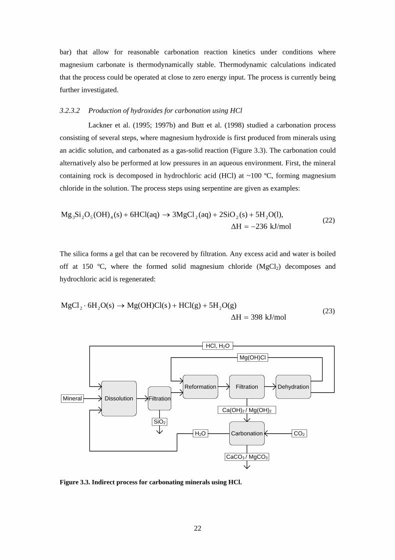
Lackner et al (1995 1997b) and Butt et al (1998) studied a carbonation process
consisting of several steps where magnesium hydroxide is first produced from minerals using
an acidic solution and carbonated as a gas-solid reaction (Figure 33) The carbonation could
alternatively also be performed at low pressures in an aqueous environment First the mineral
containing rock is decomposed in hydrochloric acid (HCl) at ~100 ordmC forming magnesium
chloride in the solution The process steps using serpentine are given as examples
kJmol236∆HO(l)5H(s)2SiO(aq)3MgCl6HCl(aq)(s)(OH)OSiMg 2224523
minus=++rarr+
(22)
The silica forms a gel that can be recovered by filtration Any excess acid and water is boiled
off at 150 ordmC where the formed solid magnesium chloride (MgCl2) decomposes and
hydrochloric acid is regenerated
kJmol398∆HO(g)5HHCl(g))Mg(OH)Cl(sO(s)6HMgCl 222
=++rarrsdot
(23)
Dehydration
Ca(OH)2 Mg(OH)2
H2O
DissolutionMineral Filtration
SiO2
Reformation Filtration
HCl H2O
Mg(OH)Cl
CaCO3 MgCO3
Carbonation CO2
Figure 33 Indirect process for carbonating minerals using HCl
22
-100
-80
-60
-40
-20
0
20
40
State of Mg
Rel
ativ
e ch
ange
in fr
ee e
nerg
y (k
Jm
ol)
Mg3Si2O5(OH)4
Mg(OH)2
MgCO3
MgCl2middot6H2O
Endothermic Exotherm
ic
Figure 34 Relative free energy changes at the main process stages of the indirect carbonation
process using HCl (after Butt et al 1998)
After solution in water magnesium hydroxide chloride forms magnesium hydroxide and
magnesium chloride
kJmol127∆H(aq)MgCl(s)Mg(OH)s)2Mg(OH)Cl( 22
OH 2
minus=+⎯⎯ rarr⎯ (24)
The magnesium hydroxide is separated while the magnesium chloride is recycled through the
acid recovery step The solid magnesium hydroxide is carbonated at high temperatures and
pressures (Equation 18 Chapter 3231) The drawback of the process is its high energy
demand for the evaporation of the aqueous solution and the large variations in free energy
resulting from the necessary formation of intermediate products (Figure 34) Newall et al
(2000) calculated the process costs to be 233 US$t CO2 sequestered Additionally to provide
for the energy requirements of the process four times more CO2 would be produced (because
of fossil fuel combustion at the power plant) than is sequestered by the process (Newall et al
2000)
The same process route could also be used for carbonating calcium silicates
(Lackner et al 1995 Newall et al 2000) In this route (Figure 33) calcium silicate is
dissolved in hydrochloric acid at 80 degC and calcium chloride (CaCl2) is produced
kJmol93∆HO(l)H(s)SiO(aq)CaCl2HCl(aq)(s)CaSiO 2223
minus=++rarr+
(25)
23
Silica is filtered out and calcium chloride reacts with magnesium hydroxide chloride
Mg(OH)Cl to produce calcium hydroxide Ca(OH)2
kJmol106∆H(aq)2MgCl(s)Ca(OH)s)2Mg(OH)Cl((aq)CaCl
22
2
minus=+rarr+
(26)
The calcium hydroxide produced is separated dissolved in water and then reacted with CO2
to produce calcium carbonate The Mg(OH)Cl is regenerated by dehydrating saturated MgCl2
at 150 degC Major drawbacks reported were the energy demand for the acid recycling stage and
a very large water demand to hydrate the Ca(OH)2 for the carbonation stage 840 t H2Ot
Ca(OH)2
In order to lower the energy requirements for dehydration several possibilities for
dissolving minerals using molten salt (MgCl2middotnH2O) instead of HCl were investigated by
Wendt et al (1998a 1998b) using thermodynamic calculations The direct carbonation of
serpentinite in a molten salt melt at 300 degC using 30 bar CO2 was considered to be the most
suitable alternative The process was calculated to have a CO2 sequestration cost of
~80 US$tCO2 but because of unavoidable losses of MgCl2 in the process during the
separation of the carbonates produced from the melt there would be a significant demand for
make-up MgCl2 (or HCl for MgCl2 production) which would probably render the process
economically unviable (Newall et al 2000)
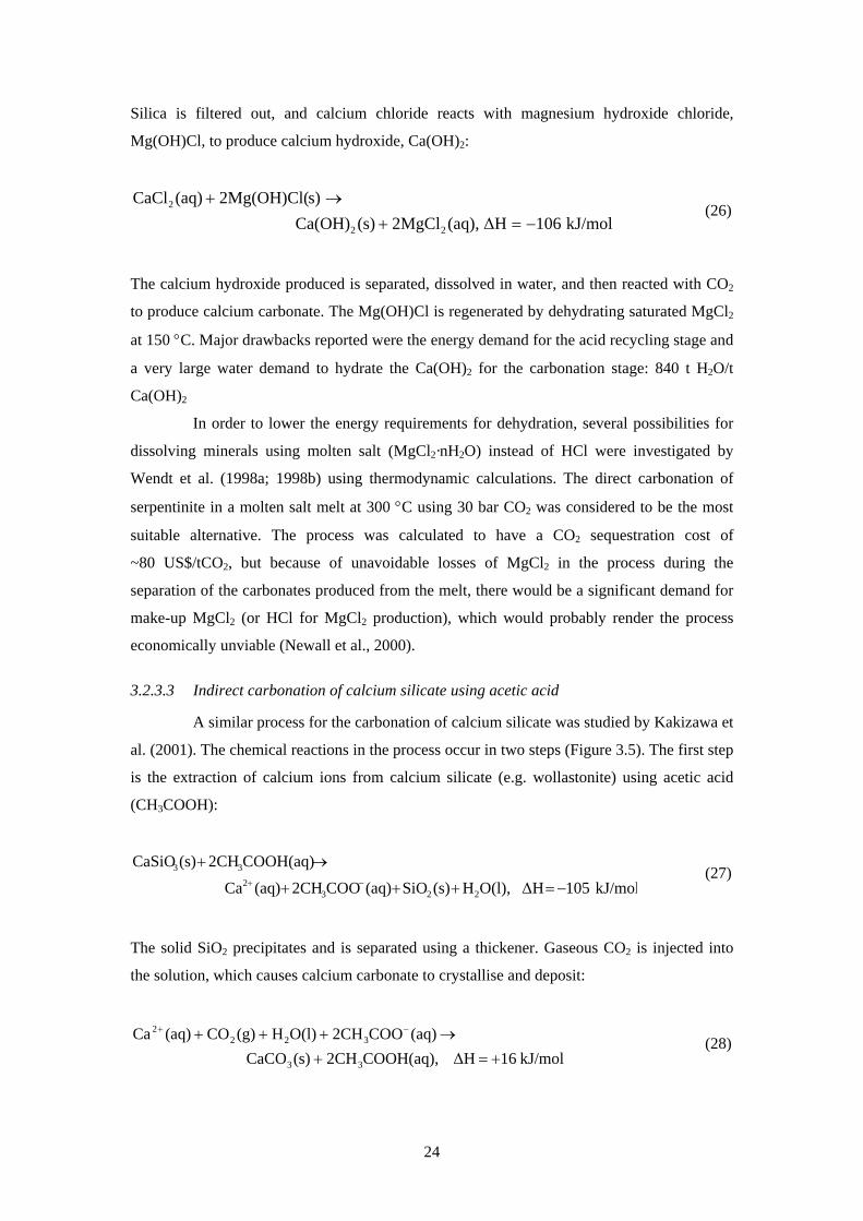
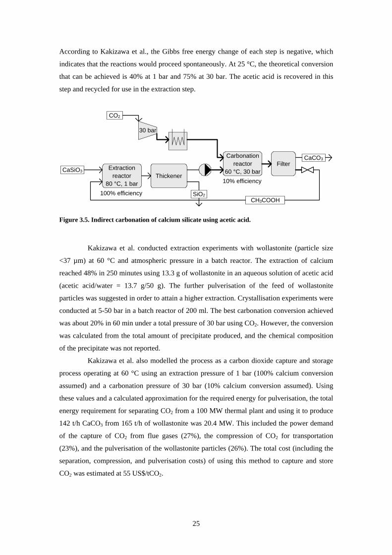
3233 Indirect carbonation of calcium silicate using acetic acid
A similar process for the carbonation of calcium silicate was studied by Kakizawa et
al (2001) The chemical reactions in the process occur in two steps (Figure 35) The first step
is the extraction of calcium ions from calcium silicate (eg wollastonite) using acetic acid
(CH3COOH)
kJmol105∆HO(l)H(s)SiO(aq)COO2CH(aq)Ca
COOH(aq)2CH(s)CaSiO
2232
33
minus=+++
rarr+minus+
(27)
The solid SiO2 precipitates and is separated using a thickener Gaseous CO2 is injected into
the solution which causes calcium carbonate to crystallise and deposit
kJmol16∆HCOOH(aq)2CH(s)CaCO(aq)COO2CHO(l)H(g)CO(aq)Ca
33
3222
+=+rarr+++ minus+
(28)
24
According to Kakizawa et al the Gibbs free energy change of each step is negative which
indicates that the reactions would proceed spontaneously At 25 degC the theoretical conversion
that can be achieved is 40 at 1 bar and 75 at 30 bar The acetic acid is recovered in this
step and recycled for use in the extraction step
CO2
CaSiO3
SiO2
Extractionreactor
80 degC 1 barThickener
Carbonationreactor
60 degC 30 barFilter
30 bar
CaCO3
CH3COOH100 efficiency
10 efficiency
Figure 35 Indirect carbonation of calcium silicate using acetic acid
Kakizawa et al conducted extraction experiments with wollastonite (particle size
lt37 microm) at 60 degC and atmospheric pressure in a batch reactor The extraction of calcium
reached 48 in 250 minutes using 133 g of wollastonite in an aqueous solution of acetic acid
(acetic acidwater = 137 g50 g) The further pulverisation of the feed of wollastonite
particles was suggested in order to attain a higher extraction Crystallisation experiments were
conducted at 5-50 bar in a batch reactor of 200 ml The best carbonation conversion achieved
was about 20 in 60 min under a total pressure of 30 bar using CO2 However the conversion
was calculated from the total amount of precipitate produced and the chemical composition
of the precipitate was not reported
Kakizawa et al also modelled the process as a carbon dioxide capture and storage
process operating at 60 degC using an extraction pressure of 1 bar (100 calcium conversion
assumed) and a carbonation pressure of 30 bar (10 calcium conversion assumed) Using
these values and a calculated approximation for the required energy for pulverisation the total
energy requirement for separating CO2 from a 100 MW thermal plant and using it to produce
142 th CaCO3 from 165 th of wollastonite was 204 MW This included the power demand
of the capture of CO2 from flue gases (27) the compression of CO2 for transportation
(23) and the pulverisation of the wollastonite particles (26) The total cost (including the
separation compression and pulverisation costs) of using this method to capture and store
CO2 was estimated at 55 US$tCO2
25
3234 Multi-step carbonation process using caustic soda
Blencoe et al (2003) developed a carbonation process that uses caustic soda (NaOH)
to dissolve silicate minerals First serpentine reacts with a concentrated solution of caustic
soda which forms crystalline brucite and an aqueous solution rich in dissolved silica
Injecting CO2 into the solution causes magnesite and a silica gel to form According to
Blencoe et al both olivine and (hydroxylated) serpentine are rapidly decomposed by an
aqueous solution of caustic soda (30-80 wt- NaOH) at relatively low temperatures (at 200
degC and below) and the pressure required to achieve rapid and efficient carbonation is about
15 bar The process was also used for carbonating calcium silicates (Blencoe et al 2004)
According to Blencoe et al (2004) 90 pure carbonate can be produced in 72 h under these
process conditions However the reaction times reported seem too long for industrial
applications and large amounts of NaOH are consumed in the process
3235 Two-step process for carbonation of serpentine
Park et al (2003) studied the dissolution of serpentine in aqueous solutions of HCl
acetic acid ethylenediaminetetraacetic acid (EDTA) orthophosphoric acid and oxalic acid
for subsequent carbonation Park found that a mixture of orthophosphoric acid oxalic acid
and EDTA gave the best extraction of magnesium from serpentine However when an acidic
solvent was used for aqueous mineral carbonation the overall carbonation rate was limited by
the dissolution of CO2 and dissociation of carbonic acid rather than the dissolution rate of the
mineral
Park and Fan (2004) proposed a two-step process for the carbonation of serpentine
First ground serpentine is dissolved at 70 ordmC and under ambient pressure using either (a) an
aqueous solution of 1 vol- orthophosphoric acid 09 wt- oxalic acid and 01 wt- EDTA
or (b) 14 M ammonium bisulphate
kJmol286∆HO(l)5H2SiO(aq)3Mg(aq)6H(s)(OH)OSiMg 22
24523
minus=++rarr+ ++
(29)
Experiments showed that after 1 h 65 of the magnesium in the serpentine had been
extracted using solvent a) while 42 had been extracted using solvent b) After this stage
solid SiO2 was separated by filtration By raising the pH of the filtrate to pH ~ 86 using
NH4OH iron dissolved from the serpentine ore precipitated as amorphous iron oxide After
the precipitated iron oxide had been removed by filtration CO2 was bubbled through the
solution at 1 atm The pH of the solution was further increased to pH ~ 95 using NH4OH
which caused relatively pure MgCO3middot3H2O to precipitate
26
Maroto-Valer et al (2005b) proposed a similar process for leaching calcium and
magnesium from silicate minerals using sulphuric acid (Equation 30) for subsequent
carbonation (Equation 31) The process steps using serpentine are given as examples
kJmol590∆H(s)2SiOO(l)5H(aq)3MgSO(aq)SO3H(s)(OH)OSiMg 224424523
minus=++rarr+
(30)
kJmol154∆H(aq)SOH(s)MgCO(aq)COH(aq)MgSO 423324
=+rarr+
(31)
Alternatively magnesium hydroxide could be produced for subsequent carbonation
kJmol3∆H(aq)SONa(s)Mg(OH)2NaOH(aq)(aq)MgSO 4224
=+rarr+
(32)
Additionally the addition of calcium nitrate or calcium hydroxide for the carbonation of the
extracted magnesium sulphate has been proposed However this would consume large
amounts of sodium hydroxide calcium nitrate or calcium hydroxide According to Maroto-
Valer et al the maximum magnesium extraction achieved from serpentine was 71 using
sulphuric acid 21 using hydrochloric acid and 25 using phosphoric acid (25 degC 12 h)
Using 41 bar CO2 at 20 ordmC a conversion of about 54 (based on CO2 consumption) of the
magnesium sulphate was achieved However it is not likely that the use of sulphuric acid
instead of hydrochloric acid would reduce the drawbacks related to the recycling of the acid
as mentioned above (see Chapter 3232)
324 Carbonation of industrial residues and by-products
The process routes described above could also be used for carbonating industrial
residues and by-products These seem to carbonate more easily and therefore do not require
process conditions as demanding as those needed for natural minerals For instance Huijgen
et al (2005) achieved a maximum carbonation degree of 74 in 30 min at 19 bar CO2 and
100 ordmC using steel slag with a particle size of lt38 microm To reach a similar conversion of
wollastonite a temperature of 200 ordmC was required (Hujgen et al 2006) Similarly Uibu et al
(2005) were able to carbonate oil shale ash in 20-40 minutes to the extent of 89-100 by
introducing CO2 into an aqueous solution at atmospheric pressure and room temperature A
carbonation degree of only 47 was achieved using CaSiO3 under the same process
conditions Although most research in this field has focused on the direct aqueous carbonation
of industrial residues and by-products (Fernaacutendez Bertos et al 2004 Johnson 2000 Huijgen
27
et al 2005 Uibu et al 2005) there are a few studies focusing specifically on the indirect
carbonation of these materials
Fujii et al (2001) studied the possibility of applying the indirect carbonation process
using acetic acid (presented in Chapter 3233) to carbonate waste concrete Waste concrete
was found to dissolve much faster than wollastonite 43 of the calcium contained in waste
concrete was extracted in 15 min at 60 ordmC with a mixture of 13 g of waste concrete 15 g of
acetic acid and 50 g of water at ambient pressure Varying the temperature of the solution
between 60-100 ordmC or the stirring speed had little effect upon the dissolution rate
Iizuka et al (2004) proposed using pressurised CO2 for carbonating waste cement
First calcium is extracted from waste cement in an aqueous solution using pressurised CO2
After extraction the pressure is reduced This causes the extracted calcium to precipitate as
calcium carbonate Experiments showed that up to 50 of the calcium in waste cement was
extracted using CO2 pressures of 9-30 bar The solution was saturated after 5-60 min The
precipitate formed was identified as calcite CaCO3 The power consumption for this route
mostly caused by the separation and compression of CO2 from a flue gas stream was
calculated to be 420 kWht CO2 which corresponds to sequestration costs of 23 US$t CO2
Katsuyama et al (2005) calculated that the production of CaCO3 using this process would
cost 136 US$t CaCO3 for desulphurisation purposes and 323 US$t for high-purity CaCO3
Stolaroff et al (2005) studied an indirect route where Ca(OH)2 and CaO from steel
slag or concrete waste was dissolved in water and carbonated with CO2 in ambient air
Experimental results showed that a major part of the available calcium dissolved in a time
scale of hours which was taken to be sufficiently fast for use in an industrial process No
carbonation experiments were performed Stolaroff et al nonetheless proposed a carbonation
process in which an aqueous solution is sprayed over a bed of slag or concrete waste The
solution dissolves CaO and Ca(OH)2 from the alkaline solids and drops into a pool underneath
the bed from which the solution is recycled through the sprayers The saturated solution
absorbs CO2 from the air producing CaCO3 that precipitates and allows more CaO and
Ca(OH)2 to dissolve The operating cost of this scheme was estimated to be 8 US$tCO2
sequestered (excluding the transportation costs of the slag) However using steelmaking slag
as raw material would increase the total costs by 25 US$tCO2 (calculated using a market
price of 8 US$t steelmaking slag)
Yogo et al (2004) proposed and tested the carbonation of waste concrete and
steelmaking slag by an indirect process using ammonium chloride (NH4Cl) or ammonium
nitrate (NH4NO3) First calcium andor magnesium ions are extracted in a solution of NH4Cl
from calcium silicate-rich materials such as waste concrete or steelmaking slags
28
kJmol42∆HOH(aq)4NH(aq)2CaCl(s)SiOCl(aq)4NHO(l)2H(s)SiO2CaO
422
422
minus=++rarr++sdot
(33)
While HCl and 2-ethylbutyric acid were more effective for dissolving the materials NH4Cl
and NH4NO3 were found to be suitable for the selective extraction of calcium In 30 minutes
44 wt- of the calcium in the steel slag had dissolved in 1 N NH4Cl while 46 wt- dissolved
in 30 minutes in 1 N NH4NO3 The solution was also found to be effective for absorbing CO2
(Equation 34) and precipitating CaCO3 (Equation 35) At an NH3 concentration of 4 and 7
CaCO3 precipitated as vaterite (a polymorph of aragonite and calcite) while calcite was the
favoured form at a 10 NH3 concentration
kJmol110∆HO(l)H(aq)CO)(NH(g)COOH(aq)2NH 232424 minus=+rarr+ (34)
kJmol19∆HCl(aq)2NH(s)CaCO(aq)CaCl(aq)CO)(NH 432324 =+rarr+ (35)
Kodama et al (2006) studied this concept further Their theoretical calculations showed that
the pH for the extraction of calcium needs to be lower than 9 while the pH for the
precipitation reaction needs to be higher than 5 The pH variations of the solvent used during
the process were in this range The maximum calcium extraction from steelmaking slag
achieved with experiments was 70 for particles smaller than 106 microm in 1 h at 60 ordmC The
selectivity for calcium and magnesium extraction was ~99 The energy consumption of the
process was calculated to be 300 kWht CO2 (which corresponds to 15 eurot CO27) captured and
stored However it was pointed out that large amounts of alkaline vapours (62 kgt CO2
2
captured) may leak from the absorption tower in the process Although the process is
suggested to be suitable for the simultaneous capture of CO from flue gases and storage to
carbonates the conversion or rate of precipitation of carbonates was not reported
325 Production of precipitated calcium carbonate
Today synthetic calcium carbonate is already produced on an industrial scale
Synthetic calcium carbonate commonly known as precipitated calcium carbonate (PCC) is
produced by three different processes a lime-soda process a calcium chloride process and a
calcinationcarbonation process In the lime-soda process calcium hydroxide is reacted with
sodium carbonate to produce a sodium hydroxide solution from which the calcium carbonate
is precipitated This process is widely used by alkali manufacturers for whom sodium
7 Calculated for an electricity price of 005 eurokWh (STAT 2003)
29
30
hydroxide recovery is the main objective and the coarse PCC produced is only a by-product
In the calcium chloride process calcium hydroxide is reacted with ammonium chloride
forming ammonia gas and a calcium chloride solution After purification this solution is
reacted with sodium carbonate to form a calcium carbonate precipitate and a sodium chloride
solution This process is the simplest of the three but requires a low-cost source of calcium
chloride if it is to be economical (Casey 1983) Therefore it is usually carried out in a
satellite facility adjacent to a Solvay process soda ash plant
Lime kiln1000 degC
Slaker35 degC
Carbonator45 degC
Filter
CaCO3
CO2
CaO
CO2
Ca(OH)2
CaCO3
H2O
CaO
CaO production
PCC plant
Figure 36 PCC production by carbonation
The third and most commonly used PCC production process is the carbonation
process (Figure 36) because it can use cheap raw material (limestone) In this process
crushed limestone is burned at about 1000 degC in a lime kiln where it decomposes into lime
(calcium oxide CaO) and carbon dioxide8
kJmol163∆H(g)COCaO(s)(s)CaCO 23 +=+rarr (36)
The dry CaO is transported to a PCC plant (located next to a paper mill) where it is slaked
(hydrated) with water at temperatures of 30-50 degC producing a calcium hydroxide slurry
(Koppinen et al 2003) The slurry production starts with stored lime being sent to a slaker
tank which is stirred by a high shear mixing agitator after which water at the desired
temperature is added and the slurry is formed9
8 reaction enthalpy calculated for 1000 degC 9 reaction enthalpy calculated for 35 degC and assuming all minerals appear as solids
31
kJmol65∆H(s)Ca(OH)O(l)HCaO(s) 22 minus=rarr+ (37)
The slurry contains undissolved calcium hydroxide calcium ions (Ca2+) and hydroxide ions
(OH-) The calcium ion concentration in the slurry depends on the solvent solubility limit
which decreases as the temperature increases Before carbonation the process slurry is
screened to remove impurities originating from the limestone The slurry is then fed to a
three-phase stirred tank reactor either at atmospheric pressure or under pressure where it
reacts with CO2 in stack gas supplied from the lime kiln of a nearby paper mill10
22322 COkJmol112∆HO(l)H(s)CaCO(g)CO(s)Ca(OH) minus=+rarr+ (38)
Adjusting the reactor temperature carbon dioxide partial pressure flow rate of the carbon
dioxide lime slurry concentration and agitator speed controls the particle size size
distribution shape and surface properties of the calcium carbonate particles The carbonation
reaction is regulated by solution equilibrium as the calcium ions are converted to calcium
carbonate and precipitated out more calcium hydroxide dissolves to equalise the
concentration of calcium ions (Ca2+) The rate of dissolution of Ca(OH)2 into Ca2+ depends on
pressure and temperature while the reaction rate of calcium ions combining with carbonate
ions is very fast Therefore the rates of formation of calcium and carbonate ions are the
primary limitations for the overall reaction rate With a pressurized reactor (1-10 bar pressure)
the overall reaction rate is higher than with an atmospheric reactor since the solubility of
carbon dioxide is higher at elevated pressure (Mathur 2001)
33 Utilisation of carbonate products
In order to provide for significant storage of CO2 large amounts of raw materials are
required as feedstock for carbonation Therefore the raw materials used for carbonation must
be abundant but also cheap However it is possible that a relatively pure carbonate product
could be valuable
Currently calcium carbonates find much wider uses than magnesium carbonates
(Zevenhoven et al 2006b) In the US alone 1 Gt of limestone was mined in the year 2003
for constructional chemical metallurgical and agricultural use (USGS 2003) Calcium
carbonate is used in growing amounts in the pulp and paper industry as a paper filler (instead
of clay) and in coatings to provide opacity high brightness and improved printability because
of its good ink receptivity (Hase et al 1998)
10 reaction enthalpy calculated for 45 degC and assuming all minerals appear as solids
Limestone is also used for producing precipitated calcium carbonate of which the
worldwide production was almost 8 Mt in 2004 (Roskill 2007) By synthesising calcium
carbonate from limestone (calcium carbonate rock) a purer calcium carbonate than natural or
ground calcium carbonate can be produced (see Chapter 325) The most important
crystalline forms of PCC are the rhombohedral calcite type the orthorhombic acicular
aragonite type and scalenohedral calcite of which the scalenohedral calcite is the favoured
form in most applications (Imppola 2000) Important qualities of the limestone used for
providing raw material for the PCC process are a low manganese and iron content since these
elements have a strongly negative influence on the brightness of the PCC product (Ciullo
1996) The iron content of PCC should be less than approximately 01 for a commercial
product (Dahlberg 2004)
Magnesium carbonate is primarily produced from mined rock especially dolomites and
is used for producing magnesium metal and basic refractory bricks It is also used in rubber
processing cosmetics and pharmaceuticals Magnesite (MgCO3) can be used as a slag former
in steelmaking furnaces in conjunction with lime (CaO) The world-wide production of
magnesite was 12 Mt during 2003 (USGS 2003)
32
4 Production of PCC from calcium silicates ndash concept and potential To determine the feasibility of a possible process to produce calcium carbonate from
calcium silicate three processes were chosen for modelling and a comparison of their power
and heat requirements11 (Paper I) indirect carbonation using hydrochloric acid (Chapter
3232 Lackner et al 1995 Newall et al 2000) indirect carbonation using acetic acid
(Chapter 3233 Kakizawa et al 2001) and the conventional PCC production method by
carbonation for comparison (Chapter 325) Unfortunately the articles by Yogo et al (2004)
Stolaroff et al (2005) and Kodama et al (2006) had not yet been published when we selected
the processes for the comparison (see Chapter 324) The process with the highest CO2
reduction potential was selected for further experimental and theoretical studies Using the
results from the process comparison the potential for CO2 emission reduction and PCC
production using domestic calcium silicate-containing resources was assessed
41 Process comparison and evaluation
The processes were modelled using Aspen Plus 121 and Outokumpu HSC 40 software
(Paper I) HSC is a computer program based on the minimisation of Gibbs free energy for
determining the chemical composition of reaction systems at thermodynamic equilibrium
Although complex chemical process can be modelled using Aspen Plus only simple steady-
state models were constructed because of the scarcity of experimental data from the calcium
silicate carbonation processes All the processes were modelled on the assumption that
sources of pure CO2 and CaSiO3 are readily available for the process at room temperature and
atmospheric pressure Chemical kinetics was not taken into account The CO2 emissions from
external heat demand were calculated assuming the combustion of heavy fuel oil that has a
heat content of 411 MJkg and CO2 emissions of 774 kg CO2GJ (STAT 2003) The CO2
emissions from electrical power demand were calculated assuming power is supplied from a
coal-fired subcritical power plant producing 830 kg CO2MWh (IEA 1993) The temperature
and pressure of the environment were set to be 25 degC and 1 bar respectively
411 PCC production from limestone
A basic model of the PCC production process was constructed (Figure 36) Since the
process was modelled as an atmospheric carbonation process there were no power
requirements for compression and pumping in the model The only heat-requiring step was 11 In order to simplify the comparison of existing and potential PCC processes all heat and power units
have been written as kilojoules per kilogram of PCC produced (kJ kg CaCO3)
33
found to be the limestone calcination since both the hydration (slaking) step and carbonation
step are exothermic Since limestone calcination takes place in a separate facility only the
calcination step was modelled
Lime kiln900 degCCaCO3
CO2
CaO
Without waste heat utilisation
Q = 2669
Lime kiln900 degCCaCO3
CaO
Q = 2244CO2
With maximum waste heat utilisation
Figure 41 Model of a lime kiln with and without waste heat utilisation (unit for results Q kJkg
CaCO3 produced)
The lowest possible temperature at which the calcination reaction (Equation 36) can
occur was found to be 894 degC at atmospheric pressure by calculating the Gibbs free energy
change for the components involved in the reaction Therefore the lime kiln temperature in
the model was set to 900 degC The calcination process was modelled using a multiphase reactor
module that calculates the product composition by Gibbs free energy minimisation The lime
kiln was found to be very energy-intensive 2669 kJkg CaCO3 is needed for calcining
calcium carbonate at 900 degC (Figure 41 left-hand model) The released carbon dioxide can
be used for preheating the limestone feed lowering the external heat requirements to 2244
kJkg CaCO3 (Figure 41 right-hand model) assuming that the flue gases are cooled down to
35 degC Although this figure might be too low in practice it shows the maximum waste heat
utilisation possible (assuming a minimum temperature difference of 10 degC) The process
produces 044 kg CO2kg CaCO3 which is later bound in the PCC production process If
heavy fuel oil were used to provide the heat required an additional 021 kg CO2kg CaCO3
would be emitted making the total emissions from the calcination process 065 kg CO2kg
CaCO3 If the waste heat could be fully used the emissions from the additional combustion
would be reduced to 017 kg CO2kg CaCO3 resulting in total emissions of 061 kg CO2kg
CaCO3 from the calcination step However in a real lime kiln excess heat is needed to
compensate for heat transfer losses According to Nordkalk (2007) the production of CaO
releases 12 t CO2t CaO (or 067 kg CO2kg CaCO3) which verifies the process calculations
and assumptions presented here
34
412 Calcium carbonate production by indirect carbonation of calcium silicate using hydrochloric acid
The process suggested for the carbonation of calcium silicates by Lackner et al
(1995) and further evaluated by Newall et al (2000) (Chapter 3232) was modelled both
without a carbonation reactor (Figure 42) and with a carbonation reactor (Figure 43) All the
chosen reactor models use Gibbs free energy minimisation for determining the product
compositions and minimum heatingcooling requirements The only significant difference
between the results from these process models and process values calculated by Newall et al
was the temperature requirement for the dehydration unit which separates HCl and H2O from
Mg(OH)Cl by evaporation According to our Aspen Plus model a temperature of 227 degC was
required for the evaporation of HCl and H2O while Newall et al used 150 degC in their
calculations The dehydration unit was as expected the most energy-demanding step
requiring 11830 kJkg Ca(OH)2 (or 8760 kJkg CaCO3) This requirement alone is over three
times the heat needed for calcining limestone The only additional energy requirement for the
process was for the separation of calcium hydroxide requiring 240 kJkg Ca(OH)2 (or 178
kJkg CaCO3) If heavy fuel oil was used to provide the heat for the process 069 kg CO2kg
CaCO3 would be emitted in the Ca(OH)2 production process which is more than the
calcination step for conventional PCC production emits (Chapter 411)
Dehydrator227 degC
Ca(OH)2
H2O
Q = 8760
Dissolutiontank
80 degCCaSiO3
Filter
SiO2
Reactor80 degC
Separator100 degC
HCl H2O
Mg(OH)Cl
Q = 180Q = -580
Q = -6440Q = -1560
Figure 42 Model of Newallrsquos process without a carbonation reactor (unit for results Q
kJkg CaCO3 produced)
In an attempt to reduce the heat demands a dry carbonation reactor was integrated
with the hydroxide production process model The carbonation reactor uses the heat released
in the carbonation process to preheat the Ca(OH)2 and CO2 prior to carbonation while the hot
products from carbonation can be used to preheat the Mg(OH)Cl stream before it enters the
dehydration unit (Figure 43) Making use of the exothermic nature of the carbonation
process the reaction temperature was raised to 560 degC which is the point at which all the heat
35
released in carbonation can be used to preheat the reactants The results from the integration
showed that the heat from the carbonation process can only supply 76 of the total heat
demand for the dehydration unit Since the carbonation process binds CO2 the net emissions
of this process would be 020 kg CO2kg CaCO3 (using heavy fuel oil to supply heat) which
is almost as much as the net emission of the current PCC production chain Therefore the
process was considered unsuitable for reducing overall CO2 emissions in PCC production
Dehydrator227 degC
Ca(OH)2
H2O
Q = 8092
Dissolutiontank
80 degCCaSiO3
Filter
SiO2
Reactor80 degC
Separator100 degC
HCl H2O
Mg(OH)Cl
Q = 180Q = -580
Q = -6440Q = -1560
Carbonator560 degCCO2
H2O
Separator110 degC
CaCO3Q = 0
Q = -667
Q = 667
Figure 43 Model of Newallrsquos process with carbonation reactor integrated (unit for results Q
kJkg CaCO3 produced)
413 Calcium carbonate production by indirect carbonation of calcium silicate using acetic acid
The carbonation process studied by Kakizawa et al (2001) (Chapter 3233) was also
modelled using Aspen Plus (Figure 44) To be able to compare our model with the process
model results presented by Kakizawa et al we chose similar conversion parameters for the
process steps a calcium extraction efficiency of 100 and a carbonate conversion of 10
were used Therefore stoichiometric reactor models that calculate the yield on the basis of
user-specified conversion efficiencies were used in our process model The partially
regenerated solution was assumed to be returned to the extraction reactor The carbonation
reactor was chosen to run at 30 bar which is the optimum pressure for the precipitation of
calcium carbonate from calcium ions in acetic acid according to Kakizawa et al (2001) In
order to achieve the high pressure of the carbonation reactor a compressor and pump were
included in the model The isentropic efficiency of the compressor that was modelled was set
to 08 and the total efficiency for the pump was set to 08 A cooler was also included to
lower the temperature of the compressed CO2 stream before it entered the reactor which in
practice may be unnecessary if the hot stream can be fed directly into the crystallisation
36
reactor to cover for the heat demand In order to further compensate for the heat demand in
the carbonation reactor the heat released in the extraction reactor can be used Therefore the
temperature of the extraction reactor was set to 80 degC while the temperature of the
carbonation reactor was set to 60 degC
The total power demand of the process that was modelled was 223 kJ per kg of
CaCO3 produced As the process is based on a carbonate-free raw material the process binds
044 kg CO2kg CaCO3 produced However the power needed to drive the compressor and
the pump accounts for 010 kg CO2kg CaCO3 reducing the net CO2 emissions avoided to
034 kg CO2kg CaCO3 If this process was used for replacing current PCC facilities an
additional 021 kg of CO2 emissions per kg of CaCO3 produced could be prevented due to the
reduced demand for calcined limestone On the basis of these calculations the acetic acid
process seems to have a high potential for simultaneously reducing CO2 emissions and
producing PCC
CO2
CaSiO3
SiO2
Extractionreactor
80 degC 1 barThickener
Carbonationreactor
60 degC 30 barFilter
30 bar
CaCO3
CH3COOH
P = 151Q = -147
P = 72
Q = 675 Q = 0
Q = -1584 Q = 0
100 efficiency
10 efficiency
Figure 44 Model of Kakizawarsquos process (unit for results Q kJkg CaCO3 produced)
42 Potential
To estimate the amount of CO2 reduction that is possible by the carbonation of natural
calcium silicate minerals rocks and steelmaking slags their carbonation potential has been
evaluated in this chapter According to the numbers presented by various sources the known
world-wide wollastonite resources can be estimated at a few hundred megatonnes of which
the Finnish resources are less than thirty megatonnes (Paper I) On the other hand basalt is
the most common igneous rock and is found widely distributed throughout the world While
the availability of basalt seems sufficient the mining of very large amounts of rock would be
needed for producing calcium carbonates However using steelmaking slag for carbonation
no mining operations would be needed but the carbonation capacity is limited
37
Table 41 Relative CO2 storage capacity by carbonation of the CaO and MgO components of
Finnish steelmaking slags in comparison to wollastonite and basalt
Slag type
CaO content
()
MgO content
()
CO2 storage
capacity
(tCO2t)
CaCO3 production
potential
(tCaCO3t)
Blast furnace slaga 405 103 043 072
Steel converter slaga 462 21 039 082
EAF slag 1b 396 110 043 071
EAF slag 2b 433 56 040 077
AOD process slag 1b 556 83 053 099
AOD process slag 2b 571 75 053 102
Chrome converter slagb 385 166 048 069
Ferrochrome slagb 14 226 026 0024
Slag mixturec 371 45 034 066
Blast furnace slagd 336 171 045 060
Steel converter slagd 543 15 044 097
Slag average 406 97 042 073
Basalte 947 673 015 017
Wollastonitef 440 no data 0
assumed
035 079
aSlag composition data supplied from Rautaruukki steel plant at Raahe bSlag composition data supplied from Outokumpu steel plant at Tornio cSlag composition data supplied from Ovako steel plant at Imatra dSlag composition data supplied from Ovako steel plant at Koverhar eBasalt composition data taken from Cox et al (1979) fWollastonite composition data supplied from Nordkalk wollastonite production at Lappeenranta
The relative CO2 storage capacity of Finnish calcium silicate-based minerals and
steelmaking slags has been summarised in Table 41 Assuming that all the MgO and CaO
components of steelmaking slag can be carbonated 260-530 kg of CO2 would theoretically be
stored per tonne of slag carbonated depending on the type of slag used Carbonating
wollastonite would bind 350 kg of CO2 per tonne of pure wollastonite (assuming a zero MgO
content) and basalt carbonation would bind 150 kg of CO2 per tonne of basalt rock Thus the
current world production of wollastonite would only allow for an annual reduction of 190-210
kt of CO2 which is an insignificant reduction compared to the annual global anthropogenic
CO2 emissions of (currently) 26 Gt The CO2 reduction capacity of carbonating steelmaking
slags is much higher using the world production estimates of steelmaking slag (256-345 Mt
USGS 2003) with the average CO2 storage capacities of slag in Table 41 the reduction
potential can be estimated as 110-150 Mt CO2a Although the potential for CO2 sequestration
in basalts is much higher the large mining operation required (about 7 t basalt needed per t
38
CO2 stored) makes it unattractive for ex situ carbonation Therefore the potential for basalt
carbonation was not further assessed The potential for reducing CO2 emissions in Finland by
carbonating domestically produced steelmaking slag (based on the production in 2004) was
calculated as 550 kt of CO2 per year (Table 42) This corresponds to a reduction of almost
9 of the CO2 emissions from Finnish steel plants If only the calcium compounds in the
steelmaking slags were used 840-860 kt of CaCO3 could be produced from the slags
Producing CaCO3 by the acetic acid process (presented in Chapter 3233) would reduce the
CO2 emissions by 290 kt of CO2 (according to the calculated process requirements presented
in Chapter 413) which corresponds to almost 5 of the CO2 emissions from Finnish steel
plants
Table 42 CO2 reduction potential by carbonation of steelmaking slags
Slag
production
Theoretical CO2 reduction
potential by slag
carbonationa
CaCO3 production
potential of slagsb
CO2 reduction by CaCO3
production from slagsc
Steel mill (kt) (kt CO2) () (kt CaCO3) (kt CO2) ()
Raahe 873 362 76 662 225 47
Koverhar 158 71 79 118 40 44
Tornio 356 98-104 143-152 40-55 14-19 21-28
Imatra 36 12 211 24 8 14
Total 1423 543-549 85-86 843-858 287-292 45-46
aCalculated using the CO2 storage capacity numbers in Table 41 ie carbonating both the MgO and CaO
components of the slags bCalculated using the CaCO3 production potential numbers in Table 41 ie CaCO3 production from carbonating
only the CaO components of the slags cCalculated using the process modelling results for carbonation of calcium silicates by acetic acid a net reduction
of 034 t CO2 per tonne of CaCO3 produced with CO2 emissions from the power production for the process taken
into account
The production of CaCO3 from the carbonation of iron and steel slag could also be a
profitable refining method for the slag products if the purity requirements for commercial
PCC could be achieved In Finland granulated blast furnace slag can be purchased for 10 eurot
which is approximately the same price as for limestone lumps used for producing lime for
PCC manufacturing (11 eurot) while the cheapest available PCC type has a price tag of 120 eurot
As a comparison Finnish fine-grained wollastonite costs 200 eurot (Dahlberg 2004) Although
the world-wide demand for PCC is forecast to rise (Roskill 2007) the market is very small in
comparison with the need for global CO2 emission reductions
39
43 Discussion
Two processes found in the literature (until the year 2004) for carbonating calcium
silicates were compared to the current lime carbonation process used by the industry A two-
step carbonation method using acetic acid was found to be the most promising process for the
PCC production of calcium silicates Using this process a net fixation of 034 t CO2 could be
achieved per ton of calcium carbonate produced The process has no external heat input
requirements and the total energy requirements seem to be much lower than the current PCC
production chain However the process produces calcium carbonate directly and not calcium
oxide meaning that more mass must be transported to the PCC facilities which would raise
the cost of transportation It would also require a relatively pure stream of CO2 Only limited
experimental data was available for this process (Kakizawa et al 2001 Fujii et al 2001)
and the quality of the calcium carbonate produced from the process had not been reported
Wollastonite seems to be too expensive and too rare to be used for the reduction of CO2
emissions by carbonation Although its chemical composition makes it an attractive material
for carbonation the limited availability of the mineral makes it too expensive Even if the
product could be sold as PCC the economic value of the reduced CO2 emissions would
probably not compensate for the use of a raw material twenty times more expensive than
limestone While basalt is more common and cheaper than wollastonite the former would
require (because of its low calcium oxide content) a mining operation five times larger than
that needed for quarrying limestone The potential for reducing CO2 emissions by the
carbonation of steelmaking slags was found to be sufficient to motivate further study While
the CO2 storage potential for using iron and steel slags is low in comparison with other CO2
storage options found in the literature the annual CO2 reduction potential of 8-21 is a
significant reduction for an individual steel mill in Finland The cost per mass of steelmaking
slags is similar to the cost per mass for limestone However steelmaking slags contain a
multitude of other elements which may require additional separation measures depending on
the carbonation process used
The potential for using the calcium carbonate produced relies on the purity and variety
of the crystal structures achievable by the carbonation process While commercial
wollastonite is relatively pure basalts and slag products would require unwanted elements to
be separated in the carbonation process to achieve a pure enough product The relatively high
price of PCC might justify the development of a carbonation process that is more expensive
than other CO2 storage alternatives
40
41
5 Production of calcium carbonate from steelmaking slag The carbonation process using acetic acid represented by Equations 27 and 28 (see also
Chapter 3233 and 413) could possibly also be used for carbonating steelmaking slags
instead of natural calcium silicates since several slag types contain calcium silicates or other
forms of calcium oxides
OHSiOCOO2CHCaCOOH2CHCaSiO 2232
33 +++rarr+ minus+ (27)
COOH2CH)(CaCOOHCOCOO2CHCa 332232 +darrrarr+++ minus+ (28)
However steelmaking slags also have high contents of other compounds such as magnesium
silicates which may react with acetic acid
OHSiOCOO2CHMgCOOH2CHMgSiO 2232
33 +++rarr+ minus+ (39)
( ) COOH2CHMgCOOHCOCOO2CHMg 332232 +darrrarr+++ minus+ (40)
In this chapter the possibility of producing calcium carbonate from steelmaking slag using
acetic acid was studied both theoretically and experimentally (Papers II-III) On the basis of
the experimental findings a process scheme was set up and its potential evaluated
51 Thermodynamic calculations
No data on the compositions of the precipitated products were provided neither by
Kakizawa et al (2001) nor Fujii et al (2001) Therefore thermodynamic equilibrium
calculations were carried out to see if calcium carbonate and magnesium carbonates are
possible products of the process before the steps were studied experimentally (Paper II) The
solution equilibrium was calculated using Outokumpu HSC 51 Although the program only
calculates chemical equilibria between pure substances and ideal solutions the calculations
should give an indication about what products can be expected from the process steps
511 Equilibrium of reaction equations
The Gibbs free energy calculations of the extraction reactions (Equations 27 and 39)
showed that both the extraction of calcium ions from CaSiO3 and magnesium ions from
MgSiO3 are thermodynamically possible throughout the temperature range where water is in
liquid form (Figure 51) The Gibbs free energy calculations of the carbonation reactions
(Equations 28 and 40) showed that the carbonation of Ca ions is already proceeding at
temperatures over 45 degC while the carbonation of Mg ions should only be possible at
temperatures over 144 degC The calculations also show that the extraction reactions are
exothermic (∆H lt 0) while the carbonation reactions are endothermic (∆H gt 0) However the
net reactions of both calcium silicate carbonation (Equations 27 and 28 together) and
magnesium silicate carbonation (Equations 39 and 40 together) are exothermic
Extraction (Equations 27 and 39)
-200
-100
0
100
200
300
0 25 50 75 100Temperature (degC)
delta
H (k
J)
-8
-4
0
4
8
12Lo
g(K
)Eq27 deltaH (kJ)Eq39 deltaH (kJ)Eq27 Log(K)Eq39 Log(K)
Carbonation (Equations 28 and 40)
-100
0
100
200
300
400
0 100 200 300Temperature (degC)
delta
H (k
J)
-2
0
2
4
6
8
Log(
K)
Eq28 deltaH (kJ)Eq40 deltaH (kJ)Eq28 log(K)Eq40 log(K)
Figure 51 Equilibrium constant (K) and reaction heat (∆H) calculated for extraction of CaSiO3
(Equation 27) and MgSiO3 (Equation 39) in acetic acid and carbonation of the solutions
(Equations 28 and 40) (Paper II)
512 Dissolution of blast furnace slag
The dissolution of blast furnace slag in acetic acid was studied in more detail by
calculating the chemical composition at thermodynamic equilibrium The input parameters
were set to simulate the extraction experiments carried out later on using 42 g of blast
furnace slag in a 250-ml aqueous solution of 333 wt- acetic acid Only the six largest
species of blast furnace slag were used as input data to simplify the results All the
compounds in the database of HSC 51 were used as potential products except for C CxHy
and all carbonates which are unlikely products from an extraction process performed in the
absence of CO2 The results and input data are summarised in Table 51 The results show that
all compounds (except for Ti) dissolve forming magnesium acetate calcium acetate and
iron(II) acetate ions Although kinetics may affect which components actually dissolve in the
time frame of hours the modelling results show that the extraction of calcium from
steelmaking slags should be theoretically possible but may require the separation of
unwanted elements from the resulting solution
42
Table 51 Thermodynamic equilibrium composition of a solution of blast furnace slag (six main
species) in acetic acid (333 wt-) and water (667 wt-) The results are presented as conversion
ratios of various elements (Paper II)
Extraction of element () Input Composition
(g)
Output Element
at 30 degC at 50 degC at 70 degC
H2O(aq) 1667 CaCH3COO+ Ca 62 65 70
CH3COOH(aq) 833 Ca2+ Ca 38 35 30
CaO 170 Si(OH)3- Si 100 100 100
SiO2 146 Mg(CH3COO)2(aq) Mg 76 70 69
MgO 043 Mg2+ Mg 24 30 31
Al2O3 039 Al3(OH)45+ Al 100 100 100
Ti 0042 Ti2+ Ti 0 0 0
Fe 0026 Fe(CH3COO)2(aq) Fe 91 89 89
S 0008 Fe2+ Fe 9 11 11
S4O3-2 S 99 99 98
S5O3-2 S 1 1 2
513 Carbonation of calcium-rich solution of acetic acid
To predict the precipitation of CaCO3 from a calcium-rich acetic acid solution the
thermodynamic equilibrium of the species and products participating in the reaction in
Equation 28 was calculated According to the results higher temperatures and pressures
favour the precipitation of calcium carbonate At a CO2 pressure of 1 bar and a solution
temperature of 25 degC only 46 of the calcium ions were predicted to form CaCO3
Calculating the equilibrium composition for the same system at a pressure of 30 bar raises the
conversion to 74 at 25 degC These results agree with the theoretical carbonation conversions
reported by Kakizawa et al 40 at 1 bar and 75 at 30 bar However adding a surplus of
acetic acid to the system seems to inhibit the formation of calcium carbonates For instance 2
additional moles of CH3COOH(aq) caused no CaCO3 formation at temperatures below 40 degC
while 4 additional moles of CH3COOH(aq) prevented CaCO3 formation below 88 degC at
atmospheric pressure Raising the CO2 pressure compensated slightly for the presence of
acetic acid However raising the conversion back to 40 when 4 additional moles of
CH3COOH(aq) are present would require a CO2 pressure of 95 bar The addition of NaOH to
a system with a 10 mol surplus of acetic acid predicted no formation of CaCO3 until the molar
amount of NaOH exceeded half that of the acetic acid (Figure 52) According to these results
a 100 conversion to CaCO3 would require practically all the surplus acetic acid to be
neutralised with NaOH
43
0
5
10
15
0 5 10 15 20
NaOH added (mol)
Equi
libriu
m c
ompo
sitio
n (m
ol)
H2OCH3COO(-)Na(+)CH3COOH(aq)Na2CO3(aq)Ca(2+)CaCO3(s)
Figure 52 Effect of the presence of NaOH in a system at thermodynamic equilibrium at 25 degC
consisting of 1 mol Ca2+ 2 mol CH3COO- 1 mol H2O 100 mol CO2 (at 1 bar) and 10 mol
CH3COOH
52 Characterisation of materials
The steelmaking slag types studied in our experiments were provided by the Raahe steel
works (Ruukki) and Tornio steel works (Outokumpu) Wollastonite from Lappeenranta
(Nordkalk) was also used for comparison Particles were sieved to 125-500 microm and only the
sieved fractions were studied while materials in powder form were used as such The
compositions of the calcium silicate-based materials used in the experiments were analysed
using X-ray fluorescence spectroscopy (XRF) The crystal orientations of the samples were
determined by X-ray diffraction (XRD) On the basis of the XRF analyses the five most
common main elements in the materials Ca Mg Al Fe and Si were measured by total acid
digestion and Inductively Coupled Plasma-Atomic Emission Spectrometry (ICP-AES) of the
resulting solution
A summary of the elemental composition of the materials used is shown in Table 52
(Paper II) All the slags tested contained similar amounts of calcium to that found in
wollastonite (39-41 wt-) except for AOD slag which contained almost 70 wt- CaO The
results of the XRD analyses are summarised in Table 53 Crystalline phases could be
identified in all materials except for the blast furnace slag sample since its crystal structure is
mostly amorphous Calcium silicate in the form of Ca2SiO4 was identified both in AOD
process slag and steel converter slag Apart from high amounts of calcium silicates the slags
44
also contained considerable amounts of other compounds such as magnesium iron and
aluminium oxides
Table 52 Elemental composition of calcium silicate-based materials used in the experiments as
determined by XRF analysis and ICP-AES analysis after total digestion (units wt-a)
Element Blast furnace
slag
(350-500 microm)
Steel converter
slag
(350-500 microm)
Electric arc
furnace slag
(125-350 microm)
AOD process
slag
(lt 125 microm)
Wollastonite
(lt 250 microm)
Analysis
method
CaO 390 414 389 694 388 ICP-AES
SiO2 257 110 212 220 322 ICP-AES
Fe2O3 0404 260 382 0252 0201 ICP-AES
MgO 119 142 605 651 0506 ICP-AES
Al2O3 864 188 634 122 117 ICP-AES
F 007 0 011 55 002 XRF
Cr 0003 0232 507 0228 0001 XRF
Ti 103 0512 264 0356 0012 XRF
Mn 0376 239 229 0076 0005 XRF
S 173 0086 0092 0273 0008 XRF aOnly elements present at gt 1 wt- are shown
Table 53 Minerals in calcium silicate-based materials identified by XRD analyses (Paper II)
Material analysed Highest peak (counts) Phases identified
Wollastonite 2500 wollastonite CaSiO3 quartz SiO2
AOD process slag 1000 fluorite CaF2 periclase MgO calcium silicate Ca2(SiO4)
Electric arc furnace slag 350 gehlenite Ca2Al(AlSiO7) merwinite Ca3Mg(SiO4)2
magnesiochromite (Mg Fe)(CrAl)2O4
Steel converter slag 300 srebrodolskite Ca2Fe2O5 lime CaO iron Fe calcium
silicate Ca2SiO4 calcium iron oxide Ca2Fe156 O25
Blast furnace slag Mostly amorphous phases
53 Dissolution of steelmaking slags
The extraction of calcium from various iron and steel slags in solutions of acetic acid
was studied using batch experiments (Paper II) The experiment setup is displayed in Figure
53 Acetic acid solutions of various concentrations were heated to 30 50 and 70 degC in a
glass reactor of 250 ml which was put in a temperature-controlled water bath The reactor
was equipped with a tap-water condenser so as to prevent losses from evaporation of the
solvent Nitrogen was continuously fed to the reactor (above the surface of the solution) at 1
lmin to prevent the CO2 in the air from interfering with the experiments The solution was
stirred using a magnetic stirrer at approximately 600-700 rpm When the temperature of the
45
solution had stabilised after heating up to the desired temperature 42 g of a calcium silicate-
based material was added to the solution The solution was stirred for 2 h and samples were
extracted during the experiment The samples were immediately filtered through syringe
membrane filters with a pore size of 045 microm and analysed for Ca Mg Si Al and Fe using
ICP-AES and Atomic Absorption Spectrophotometry (AAS) The accuracy of the ICP-AES
and AAS analyses were estimated to be plusmn 2
Gas in
Batch feed
Cooling water in
Cooling water out
T pH samples
Gas out
Temperature bath Magnetic stirrer
Figure 53 Experimental setup (Paper II)
To compare the potential for leaching calcium out from iron and steel slags various
slags were dissolved in aqueous solutions of acetic acid (33 vol-12 acetic acid and 67 vol-
distilled water initial pH of 15) at 50 degC The results from the AAS and ICP-AES analyses
(Figure 54) show that only 51 of the calcium fixed in wollastonite could be extracted
during 2 h which is similar to the results reported by Kakizawa et al (2001) (48 extracted
during 250 min see Chapter 3233) We found that the extraction of calcium from
steelmaking slags was much faster almost all the calcium from steelmaking slags dissolved in
15 minutes The extraction efficiencies were calculated by comparing the concentration of
selected elements in the filtered solution samples with the concentrations of the elements in
the raw materials (Table 52) and accounting for the loss of solution volume resulting from
sample extraction However other elements dissolve as well (see Figure 55) as predicted by
the thermodynamic equilibrium calculations The calculated extraction efficiency of blast
furnace slag (Figure 54-Figure 55) was found to exceed 100 This indicates that the
12 1 litre acetic acid = 105 kg
46
concentration of calcium in the blast furnace slag sample analysed (Table 52) was slightly
lower than in the samples used in the experiments although they were taken from the same
batch
0
20
40
60
80
100
120
000 015 030 045 100 115 130 145 200
Time in solution (hmm)
Cal
cium
ext
ract
ion
Blast furnace slag (350-500 microm)Steel converter slag (350-500 microm)Electric arc furnace slag (125-350 microm)AOD process slag (lt 125 microm)Wollastonite (lt 250 microm)
Figure 54 Extraction of calcium from various steelmaking slags and wollastonite (batch of 42 g
added at 000) in 250 ml aqueous solutions of acetic acid (33 vol- CH3COOH)
0
20
40
60
80
100
120
0 10 20 30 40 50
Moles of acetic acid in solution per moles of Ca in slag
Elem
ents
ext
ract
ed a
fter 2
h (
)
CaSiMgAlFe
Concentration of acetic acid (vol-)0 10 20 30
Figure 55 Effect of concentration of acetic acid (0 ndash 33 vol-) upon dissolution of blast furnace
slag (batch of 42 g added at 000 250 ml solution kept at 50 degC)
47
Experiments were carried out with dissolving blast furnace slag at 50 degC in aqueous
acetic acid solutions of varying concentrations The results of the AAS and ICP-AES analyses
show that the acetic acid concentration of the solution (ie the initial pH) has a dramatic effect
upon the extraction of calcium in the range 0-10 vol- acetic acid (Figure 55) Almost all of
the calcium in the batch of slag was extracted in a solution of 10 vol- acetic acid which
corresponds to 15 mol CH3COOH per mol Ca (Figure 55)
The effect of temperature upon the extraction efficiency was also investigated for
blast furnace slag at 30 and 70 degC The results of the AAS and ICP-AES analyses (Figure 56)
showed that temperature has a significant effect upon the solubility of calcium (and other
elements as well) from blast furnace slag At 30 degC the extraction is significantly slower than
at 50 degC but on the other hand more calcium can be extracted than at 50 or 70 degC This is
probably due to the solubility of calcium which decreases with increasing temperature
However this can be compensated for by increasing the acetic acid concentration in the
aqueous solution almost identical extraction efficiencies for all temperatures were achieved
using a solution concentration of 33 vol- (Teir et al 2005)
0
20
40
60
80
100
000 015 030 045 100 115 130 145 200Time in solution (hmm)
Cal
cium
ext
ract
ion
30 C
50 C
70 C
Figure 56 Extraction of calcium from blast furnace slag in aqueous solutions (250 ml) of acetic
acid (4 vol-) at 30 degC 50 degC and 70 degC (batch of 42 g added at 000)
To produce a solution suitable for the precipitation of CaCO3 ie with a high
concentration of calcium but a low concentration of silica 50 g of blast furnace slag was
dissolved in a 300-ml aqueous solution of 33 vol- CH3COOH at 70 degC for 2 hours after
which the solution was filtered using membranes with a pore size of 045 microm The filtrate
contained 17 g Cal (37 dissolved) and only 013 g Sil (03 dissolved) showing that it is
48
possible to minimise the dissolved silica content by leaching slag at 70 degC and removing the
silicon-rich gel that is formed by mechanical filtration However other separation measures
are needed to remove aluminium iron magnesium and other elements released from the
solution of the dissolved slag
54 Precipitation of carbonates
Since blast furnace slag was found to be easy to dissolve and contain low amounts of
iron (an unwanted element in PCC) blast furnace slag was selected for carbonation
experiments The experiments were performed using a similar reaction setup as in Figure 53
The possibility of producing precipitated carbonates from blast furnace slag was tested using
two different approaches 1) by injecting CO2 into filtered acidic solutions containing
dissolved blast furnace slag and 2) by first precipitating acetates by evaporation and then
injecting CO2 into aqueous solutions of the slag-derived acetates
541 Carbonation of dissolved blast furnace slag
Solutions suitable for carbonation ie with high concentrations of calcium and low
concentrations of silica were prepared similarly to those in the extraction experiments 25-50
g of blast furnace slag (05-1 mm) was dissolved in a glass reactor (250 or 500 ml) filled with
an aqueous solution of acetic acid (20-33 vol- acetic acid) at 70 ordmC for 2 h under constant N2
gas flow (1 lmin) and stirring (600-1000 rpm) after which the solution was vacuum filtered
using Supor membranes (045 microm) This produced solutions containing 11-19 g Cal 2-4 g
Mgl and 1 g All The solutions also contained small amounts of Fe and Si (01-03 gl)
The carbonation of 225 ml aqueous solutions of acetic acid and dissolved blast
furnace slag was tested at 30 50 and 70 degC After heating up to the desired temperature under
nitrogen flow (1 lmin) the nitrogen flow was switched to carbon dioxide gas flow (1 lmin)
After four hours of continuous exposure to the carbon dioxide flow the reactor was removed
from the bath and the solution was filtered The filtered solids were dried and analysed using
XRD Only 03-07 g of precipitate per litre of solution was formed in the experiments No
carbonate had been formed the dried precipitates contained magnesium acetate hydrate and
calcium acetate hydrate Because of the low initial pH of the solution (pH 3) the precipitation
of carbonates was apparently impossible (see Figure 32 and Chapter 513) In a conventional
PCC production process (Chapter 325) the precipitation of calcium carbonate occurs in an
alkaline environment Additionally Kodama et al (2006) calculated that in order to
precipitate calcium carbonate out of an aqueous solution a pH gt5 is required
In order to raise the alkalinity of the solution the precipitation experiments at 30 50
and 70 degC were repeated with the addition of sodium hydroxide (aqueous solution of 50 wt-
NaOH) during carbonation After the temperature of the prepared solution (100 ml) had
49
stabilised under nitrogen flow and the gas flow had been switched to carbon dioxide (1 lmin)
the sodium hydroxide solution was added stepwise until the acidic solution became alkaline
(pH 110-116) The change was also visibly noticeable since the solution turned from clear
to white One hour after the final addition of sodium hydroxide when the pH level had settled
at pH 7 the resulting slurry was cooled to room temperature rinsed with nitrogen gas and
filtered using syringe membrane filters with a pore size 045 microm At all three temperatures 16
ml 50 wt- NaOH was required to make the solution alkaline which corresponds to 10-11 g
of NaOH per gram of calcium in solution The XRD analyses of the filtered and dried
precipitates showed that the precipitates contained calcium carbonate in the form of aragonite
and calcite as well as sodium acetate calcium aluminium oxide and carbonates containing
both magnesium and calcium (Table 54) While calcite magnesium was the dominant form of
carbonate at 30 degC raising the temperature to 70 degC seemed to favour the formation of
aragonite and calcite
Table 54 Phases identified by XRD in filtered precipitates from carbonation experiments with
dissolved blast furnace slag where sodium hydroxide was added
Temperature
(degC)
Phases identified (in descending apparent order of magnitude)
30 Calcite magnesium ((006Mg 094Ca)(CO3))Calcium aluminium oxide (Ca3(AlO3)2
Calcite (CaCO3) Sodium acetate (CH3COONa) Aragonite (CaCO3)
50 Calcite magnesium ((006Mg 094Ca)(CO3)) Calcite (CaCO3)
Sodium acetate (CH3COONa) Aragonite (CaCO3) Calcium aluminum oxide (Ca3(AlO3)2
70 Sodium acetate (CH3COONa) Calcite (CaCO3) Aragonite (CaCO3)
Calcite magnesium ((006Mg 094Ca)(CO3)) Calcium aluminium oxide (Ca3(AlO3)2
542 Carbonation of acetates derived from blast furnace slag
Since large amounts of NaOH were required for precipitating calcium carbonate from
the solutions containing dissolved blast furnace slag the possibility of raising the alkalinity
(and recovering more acetic acid) by evaporation of the excess acetic acid was tested
Solutions were prepared similarly to those in the extraction experiments 50 g of blast furnace
slag (lt10 mm) was dissolved in a glass reactor (1000 ml) filled with an aqueous solution of
20 vol- acetic acid at 70 ordmC for 2 h under constant N2 gas flow (1 lmin) and stirring (1000
rpm) after which the solution was vacuum filtered using 5-microm filter paper (Whatman 3) The
filtrates were evaporated overnight producing a solid acetate salt precipitate for use in the
precipitation experiments XRD analyses showed that the precipitated solids contained
calcium acetate hydrates and magnesium acetate XRF analyses showed that the precipitates
50
contained mostly calcium (20 wt-) and magnesium (4 wt-) but also small amounts of Al
Si Fe and Mn (02-1 wt-) The precipitation experiments were carried out under both
atmospheric and pressurised conditions with and without additional sodium hydroxide for pH
adjustment
5421 Carbonation at atmospheric pressure
The precipitation experiments at atmospheric pressure were performed using 10 g of
acetate (derived from blast furnace slag) dissolved in water to form a solution of 200 ml The
reactor setup was similar to that in the previous carbonation experiments a glass reactor of
250 ml was set up in the temperature-controlled water bath and heated to a specific
temperature and stirred with a magnetic stirrer at 600-700 rpm Nitrogen (1 lmin) was
bubbled through the solution until the solution temperature had stabilised at the desired level
(30 50 or 70 degC) When the nitrogen flow was switched off a carbon dioxide gas flow
(1 lmin) was switched on After 20 minutes when the pH and temperature of the solution had
stabilised a specific amount (0 2 5 or 20 ml) of a sodium hydroxide solution (50 wt-) was
introduced into the solution The pH of the solution was allowed to stabilise during 2frac14 h
after which the carbon dioxide flow was switched off and the solution was filtered (Whatman
50 3-microm filter paper) The filtered precipitate was washed and dried after which it was
analysed using XRD and XRF The carbonate content was calculated from the carbon content
measured using Total Carbon (TC) analysis
The experiments performed at 30 50 and 70 ordmC produced only 18-24 g of precipitate
per kg of acetate in solution Of these only the precipitate produced at 70 ordmC contained traces
of calcite The solutions carbonated with the addition of NaOH produced 150-380 g of
precipitate per kg of acetate used (Figure 57) The temperature had a very small effect upon
the amount of precipitate formed in comparison to the addition of sodium hydroxide which
clearly increased precipitation However adding more than 2 mol NaOH per mol Ca in
solution did not have any significant effect on the precipitate yield Apparently 2 mol NaOH
per mol calcium in solution (about 2 g of NaOH per g of Ca) is required for maximal yield
However this is significantly less than in the previous experiments in which at least 11 g of
NaOH per g of Ca was required (see Chapter 541) All the precipitates formed using NaOH
addition contained high amounts of calcium carbonates in the form of calcite aragonite and
calcite magnesium (01 mol Mg and 09 mol Ca per mol CO3) However other elements too
such as Al Si Na Mn and Fe were found in the precipitates (Figure 58) Assuming that all
the carbon was bound as calcium carbonates the precipitates produced when using 20 and
77 mol NaOH per mol calcium contained roughly 80-90 wt- calcium carbonate (Figure
58) This corresponds to a calcium carbonate conversion of 60-70 of the calcium in the
solutions Very little magnesium precipitated in comparison to calcium and it appeared only
51
as calcite magnesium The magnesium content in the precipitate was found to depend linearly
on the amount of sodium hydroxide added with the precipitate produced using 77 mol
NaOHmol Ca containing 3 wt- Mg
0
50
100
150
200
250
300
350
400
0 5 10 15 20
NaOH added (ml)
Prec
ipita
te fo
rmed
(g
kg a
ceta
te)
0 2 4 6 8mol NaOH added per mol Ca
Figure 57 Effect of addition of NaOH on precipitate formation when carbonating aqueous
solutions containing 10 g acetate (20 wt- Ca) derived from blast furnace slag at 30 ordmC
20 mol NaOHmol Ca at 30 degC
08 mol NaOHmol Ca at 30 oC
20 mol NaOHmol Ca at 50 degC
20 mol NaOHmol Ca at 70 degC
77 mol NaOHmol Ca at 30 degC
0
10
20
30
40
50
60
70
80
90
100Others
Fe
Mn
Na2O
SiO2
Al2O3
MgO
CaO
C
CaCO3
Figure 58 Elemental compositions of the dried and washed precipitates from the experiments
with carbonating slag-derived acetate solutions as determined by XRF and total carbon content
analyses (units wt-)
52
5422 Carbonation at elevated pressures
Kakizawa et al (2001) achieved the best precipitation efficiency at a carbon dioxide
pressure of 30 bar using aqueous solutions of pure calcium acetate Therefore we performed
two additional precipitation experiments at 30 bar 10 g of acetate produced from blast
furnace slag was dissolved in water producing an aqueous solution of 100 ml A volume of 5
ml of aqueous sodium hydroxide solution (50 wt-) was added to one of the acetate solutions
prepared while the other was used without additives The solution was put in a closed reactor
vessel which was heated to 50 degC using a water-heated copper coil (see Figure 59) and
stirred using a magnetic stirrer at 1000 rpm When the temperature of the solution had
stabilised at 50 degC the reactor was pressurised to 30 bar using pure carbon dioxide After 2
hours the pressure was lowered to 1 bar and the solution was filtered through a pressurised
filtration unit (utilising membrane filters with a pore size of 045 microm) The filtered precipitate
was washed and dried after which it was analysed using XRD XRF and total carbon
analysis
TP P
P
N2 CO2
Magneticstirrer
Temperature-controlled bath
Safety valve
Ventilation valve
Figure 59 Experimental setup used for acetate solution carbonation experiments performed at
30 bar total pressure and 50 ordmC
In the experiment performed without the addition of NaOH only 30 g of precipitate was
formed per kg of acetate used which was slightly more than in the atmospheric experiments
(18-24 g) The precipitate consisted only of amorphous phases but the amount was not enough
for performing XRF analysis In the experiment performed with the addition of NaOH 380 g
53
of precipitate was formed per kilogram of acetate used The precipitate consisted mostly of
calcium carbonate as calcite magnesium The yield and the composition of the precipitate
produced at a total pressure of 30 bar were similar to the yield and composition of the
precipitate produced at atmospheric pressure
55 Process evaluation
According to the experimental results the excess of acetic acid required for completely
dissolving blast furnace slag seems to prevent the precipitation of calcium carbonate While
this obstacle can be overcome by increasing the alkalinity of the solution by the addition of
sodium hydroxide the amount of sodium hydroxide required was found to be large The
evaporation and condensation of the acidic solution allows for a relatively easy recycling of a
large part of the acid However evaporation requires energy and its production causes CO2
emissions in most cases Additionally the production of sodium hydroxide is known to be
energy-intensive An advantage of the process is that the pressurisation of the CO2 is not
necessary Therefore a process concept was set up (Figure 510) based on the experimental
procedures and results and its energy requirements were evaluated (Paper III)
Blast furnaceslag 43 kg
Spent acetatesolution
Dissolutionat 70 ordmC
(XCa = 100)
Thickener
Evaporationat 120 ordmC
Carbonationat 30 ordmC
(XCa = 68)
Thickener
Condenser
Acetic acid52 kg
Gel residue11 kg
NaOH 26 kg
Precipitate25 kg
(89 wt- CaCO3)
CO2 (1 bar)10 kg
Acetate69 kg
Acetic acid(~97 wt-) 23 kg
Figure 510 Process scheme for producing calcium carbonate from blast furnace slag Numbers
based on experimentally verified results
The best conditions for precipitating calcium carbonate from the acetate solutions was
found to be at 30 ordmC and 1 bar CO2 using 2 mol NaOH per mol Ca in the acetate solution (or
038 kg of NaOH per kg of acetate produced) These conditions produced 036 kg of
precipitate per kg of acetate used The precipitate contained 89 wt- CaCO3 (as calcite) and
the conversion of calcium acetate to calcium carbonate was 68 Our dissolution experiments
54
showed that using 6 l of acetic acid per kg of blast furnace slag a complete dissolution of the
slag was possible Using these compositions 43 kg of blast furnace slag would be required
per kg of CO2 stored as calcium carbonate This would produce 25 kg of precipitated
carbonates (89 wt- CaCO3) and 11 kg of SiO2 but also require 26 kg of NaOH for the
carbonation step While the excess acid could be recycled by evaporation and condensation
52 kg of acetic acid is spent on producing the acetates
The heat requirements13 of the main process steps were calculated from reaction
enthalpies using Outokumpursquos HSC 51 software The reaction heat for the dissolution of
blast furnace slag in acetic acid at 70 degC was simplified using wollastonite data instead of the
actual blast furnace slag composition (Equation 27) The reaction is exothermic producing
about 985 kJ of heat per kilogram of wollastonite dissolved As only part of the acetic acid
reacts with blast furnace slag to produce acetate and water the excess acetic acid would have
to be evaporated Raising the temperature to 120 degC and evaporating the solution would
require 930 kJ of heat per kg of solution evaporated The produced acetate would be dissolved
in water after which carbon dioxide and sodium hydroxide would be introduced Since
neither temperature nor pressure was found to have a significant effect on the carbonation
process the acetate would be carbonated at 30 degC and a carbon dioxide pressure of 1 bar (ie
there would be no need for reactor pressurisation) The heat requirement of this process step
can be calculated from Equation 41
( )2233
223
COkJmol93∆HO(l)HCOONa(aq)2CH(s)CaCO(g)CO2NaOH(aq)(aq)COOCHCa
minus=++
rarr++ (41)
According to the calculations the carbonation step is also exothermic producing about 21
MJ of low-temperature (30degC) heat per kilogram of carbon dioxide stored The acetic acid and
sodium hydroxide spent in this step would have to be purchased or regenerated Sodium
hydroxide can be produced through the electrolysis of an aqueous solution of sodium
chloride The amount of electricity needed for the electrolysis can be calculated as the change
in Gibbs free energy for the reaction (Equation 42)
NaOHkJmol208∆G2NaOH(aq)(g)H(g)ClO(l)2H2NaCl(aq) 222
=++rarr+
(42)
13 All reaction enthalpies are calculated at 25 degC (using Outokumpu HSC 51) unless stated otherwise
55
This shows that approximately 52 MJ of electricity would be required to produce 1 kilogram
of sodium hydroxide The most common acetic acid manufacturing process is methanol
carbonylation in which methanol reacts with carbon monoxide but requires methanol and
carbon monoxide as raw materials
COOHCHkJmol129∆HCOOH(aq)CHCO(g)OH(aq)CH 333 minus=rarr+ (43)
Heat calculations showed that most process steps do not require external energy
input However evaporation requires 20 MJ of heat (at ge 120 degC) for separating the solution
from the acetate required to bind 1 kilogram of carbon dioxide Since the carbon dioxide
emission factor for hard coal combustion is 946 g CO2MJ (STAT 2003) producing the heat
required for this process step would emit twice the amount of carbon dioxide stored by the
process Since the temperature required for the evaporation step is quite low it is very likely
that the required heat could be acquired by process integration using waste heat from the
steelmaking plant itself However this requires the carbonation plant to be situated near the
steel mill
Since the carbon dioxide emissions from a coal-fired power plant are roughly 800
kgMWh (IEA 1993) generating the electricity required for producing sodium hydroxide
would produce three times the amount of carbon dioxide bound in the carbonation step
Although hydrogen and chlorine gas are both by-products of sodium hydroxide production
the electricity requirements of electrolysis make the process described above unsuitable for
carbon dioxide storage unless the sodium hydroxide can either be replaced by a cheaper
alkaline (waste) stream or recycled
If waste heat and alkaline waste solutions from other processes could be supplied to
the carbonation process no carbon dioxide emissions would be generated Instead 025 kg of
carbon dioxide would be stored per kilogram of blast furnace slag used in the process The
conventional PCC production chain produces approximately 02 kilogram of carbon dioxide
per kilogram of calcium carbonate produced (Chapter 411) If PCC production facilities
using blast furnace slag replaced conventional PCC production facilities it would prevent the
CO2 emissions caused by calcination However these savings are small in comparison with
the carbon dioxide generated from sodium hydroxide production An additional benefit would
be achieved if the carbonation step could directly use the carbon dioxide in flue gases without
separation as conventional PCC production processes do However the purity requirements
of carbon dioxide the suitability of the produced precipitate for use as PCC and process
integration as well as the recycling of sodium hydroxide must be further investigated
56
56 Discussion
The possibility of producing calcium carbonate from steelmaking slags using acetic
acid was studied According to the calculations the dissolution of calcium silicate and blast
furnace slag was thermodynamically favourable in the studied temperature range (30-70 degC)
Experiments showed that the total dissolution of the steelmaking slags tested was faster and
that a higher conversion was achieved than with the dissolution of wollastonite While only
50 of the calcium in wollastonite dissolved in an aqueous solution of acetic acid at 50 ordmC
80-100 of the calcium in steelmaking slag was extracted under similar conditions Other
elements such as silicon iron aluminium and magnesium dissolved as well Because of the
high acid concentrations used the experiment (33 vol- acetic acid) no connection between
the dissolution rates of the calcium silicates and the crystallinity of the material was observed
Using solutions with leaner concentrations of acid would probably have shown more
differences between the leaching behaviour of the materials
The effect of various process parameters upon the dissolution step was tested using
blast furnace slag Experiments showed that for the complete dissolution of blast furnace slag
15 mol acetic acid was required per mol calcium in slag (at 50 ordmC) which is 7-8 times the
theoretical requirements for extracting calcium (Equation 27) One reason for the large acid
requirement is that other elements in slag react with the acid as well However when the
dissolution was complete the pH of the solutions was still about 3-4 which indicates that not
all the acid had been neutralised When the temperature of the solution was raised less
calcium dissolved but this can be compensated for by using higher concentrations of acid At
70 ordmC and 80 ordmC (and large concentrations of dissolved slag) almost all the dissolved silicon
precipitated as gel and was successfully removed by filtration However other separation
measures will be needed to remove aluminium iron magnesium and other elements released
from the slag or to prevent these elements from ending up in the carbonate product
Thermodynamic calculations predicted that the precipitation of carbonates from acetate
solutions would be favourable at temperatures over 45 degC However experiments with
carbonating solutions of dissolved blast furnace slag and acetic acid produced no carbonate
precipitate during 4 h at 30-70 degC Thermodynamic calculations verified that the solution was
too acidic to allow for carbonate precipitation While the addition of sodium hydroxide raised
the pH of the solution resulting in the formation of a precipitate containing carbonates a
considerable amount of sodium hydroxide was required which also reduces the amount of
acetic acid that can be recovered for re-use By evaporating the solution containing dissolved
slag and mixing the precipitated acetate with water prior to carbonation the sodium hydroxide
requirements were reduced to the stoichiometric requirements (of Equation 41) Bubbling
CO2 gas through the acetate solution precipitated relatively pure (80-90) calcium carbonate
57
Based on the results it seems that the process concept suggested by Kakizawa et al
(2001) cannot work as such The extraction of calcium from the calcium silicate-containing
material seems to demand a surplus of acetic acid for achieving a significant extraction Since
only part of the acid is consumed the resulting solution is acidic which in turns prevents
precipitation of calcium carbonate Also the acetic acid that is formed simultaneously with
calcium carbonate in the carbonation step (Equation 28) lowers the solution pH and makes the
precipitation of calcium carbonate unfavourable In order to favour precipitation of calcium
carbonate the acid needs to be neutralised
Our experimental results showed that improving the process concept by recycling the
surplus of acid by evaporation and adding sodium hydroxide to the carbonation step allows
for calcium carbonate to be produced Preliminary calculations showed that the heat
requirements for the evaporation of the acetic acid are large but could be covered by using
low-grade waste heat (120 ordmC) from other industrial processes The requirements for sodium
hydroxide and make-up acetic acid were also relatively large requiring the recovery and
processing of the produced sodium acetate solution However the large amount of dissolved
impurities would probably make recovery of the solution difficult Since the precipitate
produced contained a high amount of impurities (10-20) the product would probably not
have a high value Therefore the use of acetic acid does not seem to be a feasible option for
producing carbonates from blast furnace slag
Although the results demonstrate that it is possible to produce relatively pure calcite
(80-90) from blast furnace slag and CO2 the acetic acid carbonation process does not seem
feasible for reducing CO2 emissions While acetic acid dissolves steelmaking slag easily it is
quite expensive and also dissolves many unwanted elements from slags A solvent that
extracts calcium selectively from slags (eg Yogo et al 2004) would significantly reduce the
requirements for additional separation measures
58
59
6 Production of magnesium carbonate from serpentinite Although steelmaking slags can be used for the fixation of CO2 the world-wide CO2
storage potential using these (110-150 Mt CO2a) is small compared to the anthropogenic CO2
emissions (24 Gt CO2a) This also applies to Finlandrsquos slag resources in comparison to
national CO2 emissions For large-scale CO2 storage purposes magnesium silicates such as
serpentine are more interesting because of their large CO2 storage potential and availability
(see Chapter 312) However they are known to be more difficult to carbonate than
steelmaking slags In order to test whether pure magnesium carbonate could be produced from
serpentine while simultaneously storing CO2 a series of experiments were performed using
similar experimental procedures to those described in Chapter 5 (Papers IV and V) Since
magnesium silicates are harder to dissolve than steelmaking slags an extensive solvent
selection study was carried out followed by experiments with selected solvents for
constructing a kinetic model of the dissolution process Carbonation experiments were
subsequently carried out with the most promising solvents On the basis of the outcome of the
experiments the feasibility of the CO2 storage method was evaluated (Paper VI)
61 Characterisation of serpentinite
A batch of 7 kg of serpentinite rock was selected from the stockpile of the Hitura nickel
mine (located in central Finland and currently owned by Belvedere Resources Ltd) ground to
a median diameter of 01 mm (lt05 mm) and sieved to various fractions The serpentinite
was analysed using XRD XRF total acid digestion with ICP-AES and Total Organic Carbon
(TOC) analyses A summary of the results from the analysis of the serpentinite is shown in
Table 61 The ICP-AES values were used in calculations instead of the XRF values where
available On the basis of the Mg content and Fe content of the sample and XRD data (Figure
61) the serpentinite consisted of 83 wt- serpentine (Mg3Si2O5(OH)4 chrysotile lizardite
and antigorite) and 14 wt- magnetite (Fe3O4)
Table 61 Composition of serpentinite used in experiments (74-125 microm units wt-)
MgOa SiO2b Fea Al2O3
a CaOa Sb Cra Nia Clb CO3c
362 403 101 008 048 052 0007 002 021 lt 01
aAs determined by ICP-AES bAs determined by XRF cAs determined by TOC
Figure 61 X-Ray diffractogram of the sieved (74-125 microm) serpentinite fraction
62 Selection of solvent
Instead of all the experiments being performed with one selected solvent (as in the
study of steelmaking slags in Chapter 5) a series of tests were performed to select a solvent
suitable for extracting magnesium from serpentinite (Paper IV) Common mineral acids (HCl
H2SO4 HNO3) and weak organic acids (HCOOH and CH3COOH) were tested for dissolving
serpentinite Both acids and bases are known to extract magnesium from its silicates The high
alkalinity of bases favours the formation of carbonates Therefore the dissolution of
serpentinite was also tested using three common bases NaOH KOH and NH3 Since
ammonium salts have been found to dissolve calcium and magnesium selectively from
steelmaking slags (Yogo et al 2004) NH4Cl NH4NO3 and (NH4)2SO4 were also tested
A batch of 1 g of serpentinite (74-125 microm) was dissolved in 50 ml aqueous solutions of
1 2 and 4 M concentrations of the respective solvent One test was also performed with
distilled water The solutions were continuously stirred for 1 h at 100 rpm 20 degC and 1 atm
after which the solutions were immediately filtered with 045 microm membrane filters Since the
serpentinite contained very low concentrations of other metals only the concentrations of Mg
Fe and Si in the filtrates were measured with ICP-AES
All the acids tested were able to extract 3-26 of the magnesium from serpentinite in 1
h while water extracted only 02 (Figure 62) However none of the acids tested extracted
Mg selectively from serpentinite Fe (2-16) and some Si (0-3) were also extracted H2SO4
was most efficient at extracting magnesium from serpentinite followed by HCl HNO3
HCOOH and CH3COOH (listed in descending order of magnesium extraction efficiency)
Higher acid concentrations resulted in slightly more magnesium and iron ions being
60
dissolved except for the solutions of CH3COOH which behaved more irregularly The
ammonium salt solutions tested extracted only 03-05 of the magnesium from serpentinite
in 1 h However the ammonium salt solutions were the only solvents tested that seemed to
extract magnesium selectively no iron or silicon concentration was found in the salt solutions
after filtration No measurable amount of magnesium or iron and no more than 03 of the
silicon had dissolved in any of the alkaline solutions tested Therefore H2SO4 HCl and
HNO3 were selected for further studies which are reported below
0
10
20
30
0 1 2 3 4Solvent concentration (M)
X Mg
H2SO4HClHNO3HCOOHCH3COOH(NH4)2SO4NH4ClNH4NO3NH3NaOHKOH
Figure 62 Extraction of magnesium from serpentinite (74-125 microm) in 1 2 and 4 M
concentrations of solvent (1 h 20 degC)
63 Effect of concentration temperature and particle size on dissolution of serpentinite
The effect of acid concentration was studied by extending the solvent experiments
presented in the previous chapter with 01 02 and 05 M concentrations of HCl or HNO3
The results of the ICP-AES analyses (Figure 63) showed that even dilute acid concentrations
(01 M) significantly increased the extraction of Mg and Fe in comparison to that of pure
water The extraction of silica did not occur in 0-05 M solutions of acid
Experiments for determining the dissolution rate of serpentinite in H2SO4 HCl and
HNO3 were carried out in an open spherical glass batch reactor (1 atm) heated by a
temperature-controlled water bath and equipped with a water-cooled condenser to minimise
evaporation losses (setup similar to that presented in Figure 53) 500 ml of the desired
solvent (as a 2 M solution) was added to the reaction vessel The solutions were well mixed
61
using a magnetic stirrer set to 600-700 rpm After the temperature had stabilised (at
30 50 or 70 degC) 10 g of serpentinite (74-125 microm) was added to the solution Solution
samples (5 ml per sample) were extracted while the experiment progressed and immediately
filtered with 045 microm membrane filters The Mg Fe and Si concentrations of the samples
were measured using ICP-AES
0
10
20
0 1 2 3 4Solvent concentration (M)
Extra
ctio
n (w
t-)
Mg (HCl)
Mg (HNO3)
Fe (HCl)
Fe (HNO3)
Si (HCl)
Si (HNO3)
Figure 63 Extraction of Mg Fe and Si from serpentinite (74-125 microm) in various concentrations
of HNO3 or HCl (1 h 20 degC)
0
20
40
60
80
100
120
000 030 100 130 200Reaction time (hmm)
X Mg
70 degC 50 degC 30 degC
Figure 64 Effect of temperature on extraction
of Mg from 74-125 microm serpentinite using 2 M
H2SO4
0
20
40
60
80
100
120
000 030 100 130 200Reaction time (hmm)
X Mg
70 degC 50 degC 30 degC
Figure 65 Effect of temperature on extraction
of Mg from 74-125 microm serpentinite using 2 M
HNO3
Figures 64-66 show that higher temperatures yield higher reaction rates for each acid
tested At 70 degC the acids tested were able to leach all of the magnesium in serpentinite
62
within 1-2 h However 38-67 of the iron as well as 3 of the silicon in serpentinite was
also dissolved Apparently magnesium and iron are extracted leaving behind mostly silica
and small quantities of magnetite While nitric acid was slower at dissolving serpentinite than
the other acids it was more selective in extracting magnesium at 70 degC
The effect of the particle size was analysed similarly in 2 M HCl at 70 degC using sieved
serpentinite fractions of 74-125 125-250 250-350 and 350-500 microm The extraction of
magnesium (Figure 67) was most effective for the smallest particle sizes (74-125 microm)
However particle size did not seem to have a significant effect on magnesium extraction from
the other fractions tested which gave almost equal magnesium extraction rates settling at
78-81 extraction after 1-2 h
0
20
40
60
80
100
120
000 030 100 130 200Reaction time (hmm)
X Mg
70 degC 50 degC 30 degC
Figure 66 Effect of temperature on extraction
of Mg from 74-125 microm serpentinite using 2 M
HCl
0
20
40
60
80
100
000 030 100 130 200Reaction time (hmm)
X Mg
0074-0125 mm0125-025 mm025-035 mm035-05 mm
Figure 67 Effect of particle size on extraction
of Mg from serpentinite using 2 M HCl
64 Dissolution kinetics
The data from the experiments with HCl HNO3 and H2SO4 (Figures 64-66) were used
for determining the kinetic parameters and rate-controlling step of the extraction process
Heterogeneous fluid-solid reactions may be represented by
(44) productssolidbBfluidA rarr+ )()(
In these reactions the rate is generally controlled by one of the following steps diffusion
through the fluid film (quantifying for external mass transfer) diffusion through the ldquoashrdquo (or
solid product) layer on the particle surface or the chemical reaction at the reaction surface
The rate of the process is controlled by the slowest of these sequential steps The experimental
data were analysed according to the integral analysis method (Levenspiel 1972) The integral
63
analysis method puts a selected model to test by integrating its rate equation and comparing
the predicted concentration-versus-time curve with the experimental concentration-versus-
time data The experimental data were fitted to integral rate equations for five common
unreacted-core models representing film diffusion control product layer diffusion control
and chemical reaction control for both unchanging size and shrinking size (ie the product
layer stays on the particle or is removed see Figure 68)
Time Time
Time Time
Low conversion High conversion
Ash Shrinking unreacted core
Shrinking unreacted particle
Constantsizeparticles
Shrinkingsphere
Figure 68 According to the unreacted-core models the reaction proceeds at a narrow front that
moves into the solid particle The reactant is completely converted as the front passes by (after
Levenspiel 1972)
Since magnesium exists as serpentine (Mg3Si2O5(OH)4) in serpentinite the extraction
of magnesium in the acids tested can be described in the form of Equation 44
OH65SiO
31ClMg
21(OH)OSiMg
61HCl 22
24523 +++rarr+ minus+ (45)
OH35SiO
32SOMg(OH)OSiMg
31SOH 22
24
2452342 +++rarr+ minus+ (46)
OH65SiO
31NOMg
21(OH)OSiMg
61HNO 223
245233 +++rarr+ minus+ (47)
The experimental data (magnesium extracted vs time) from all three solvents was plotted
against the integral rate equations According to the regression correlation coefficients (Table
62 and Table 63) the experimental data from all three solvents were best fitted towards the
64
integral rate equation for product layer diffusion (of constant size spherical particles) (Figures
69-611)
( ) ( )[ ] ( ) ( )[ ]BBBBAe
B XXk
XXCbD
rt minus+minusminus=minus+minusminus= 121311121316
32322ρ
(48)
This unreacted-core model equation for product layer diffusion control follows from equating
the rate of weight loss of a spherical particle to the rate of diffusion of reactant (in this case
acid) through the product layer Its derivation as well as that for rate control by chemical
kinetics or film diffusion (ie external mass transfer) and particles without a product layer
(ie shrinking sphere) are given by Levenspiel (1972)
Table 62 Multiple regression coefficients for experimental kinetic data fitted to unreacted-core
models of constant size spherical particles (Paper IV)
Model Integral rate equation 2max
2min RR minus
Product layer diffusion ( ) ( )BB XXkt minus+minusminus= 12131 32 0936 ndash 0998
Chemical reaction controls ( ) 3111 BXkt minusminus= 0661 ndash 0901
Film diffusion BXkt = -0760 ndash 0863
Table 63 Multiple regression coefficients for experimental kinetic data fitted to unreacted-core
models of small shrinking spherical particles (Paper IV)
Model Integral rate equation 2max
2min RR minus
Chemical reaction controls ( ) 3111 BXkt minusminus= 0661 ndash 0901
Film diffusion ( ) 3211 BXkt minusminus= 0483 ndash 0882
The apparent rate constants were determined from the slope of the lines in Figures 69-611
The apparent extraction rate constant can be used for determining the temperature dependency
by Arrheniusrsquo law
RTEekk
0minus= (49)
65
kt = 33007bull10-6tR 2 = 09458
kt = 61773bull10-6tR 2 = 09715
kt = 12675bull10-6tR 2 = 09957
0
02
04
06
08
1
0 2000 4000 6000 8000
Reaction time (s)
70 degC50 degC30 degC
()
()
Mg
Mg
XX
minus+
minusminus
12
13
13
2
Figure 69 1 ndash 3(1 ndash XMg)23 + 2(1 ndash XMg) vs reaction temperature for extraction of Mg from 74-
125 microm serpentinite in 2 M HCl (Paper IV)
kt = 41671bull10-6tR 2 = 09394
kt = 70599bull10-6tR 2 = 09395
kt = 17688bull10-6tR 2 = 0998
0
02
04
06
08
1
0 2000 4000 6000 8000
Reaction time (s)
70 degC50 degC30 degC
()
()
Mg
Mg
XX
minus+
minusminus
12
13
13
2
Figure 610 1 ndash 3(1 ndash XMg)23 + 2(1 ndash XMg) vs reaction temperature for extraction of Mg from 74-
125 microm serpentinite in 2 M H2SO4 (Paper IV)
kt = 15326bull10-6tR 2 = 09355
kt = 38764bull10-6tR 2 = 09913
kt = 49817bull10-6tR 2 = 0988
0
02
04
06
08
1
0 2000 4000 6000 8000
Reaction time (s)
70 degC50 degC30 degC
()
()
Mg
Mg
XX
minus+
minusminus
12
13
13
2
Figure 611 1 ndash 3(1 ndash XMg)23 + 2(1 ndash XMg) vs reaction temperature for extraction of Mg from 74-
125 microm serpentinite in 2 M HNO3 (Paper IV)
66
By plotting the apparent rate constants for each experiment in an Arrhenius plot (Figure 612)
the activation energies (E) and the frequency factors (k0) were determined the results are
shown in Table 64 The order of the activation energies found in the present study is similar
to those found in similar studies with roasted serpentine ore and natural olivine (Fouda et al
1996a-b Apostolidis and Distin 1978 Jonckbloedt 1998 Chen and Brantley 2000 Haumlnchen
et al 2006) No previous kinetic studies on untreated serpentine ore were found in the open
literature for comparison to this work
y = -(894plusmn070)x + 173plusmn22
y = -(819plusmn088)x + 160plusmn27
y = -(846plusmn044)x + 166plusmn14
-13
-12
-11
-10
-9
-8
-728 29 3 31 32 33 34
1000T (K-1)
ln k
H2SO4HClHNO3
H2SO4
HClHNO3
Figure 612 Arrhenius plot for extraction of Mg from 74-125 microm serpentinite in 2 M H2SO4 2 M
HCl or 2 M HNO3 including standard errors for the coefficients of the trend lines (Paper IV)
Table 64 Activation energy and frequency factor calculated using the coefficients of the trend
lines of the Arrhenius plots in Figure 612 (Paper IV)
Solvent Activation energy E [kJ mol-1] Frequency factor k0 [s-1]
H2SO4 681 plusmn 73 86middot106
HCl 704 plusmn 37 16middot107
HNO3 743 plusmn 58 34middot107
The results indicate that the rate-limiting step for the dissolution of serpentinite in HCl
H2SO4 and HNO3 is product (or ldquoashrdquo) layer diffusion This result is in agreement with Luce
et al (1972) who found that the diffusion of ions either in the mineral lattice itself or through
a product layer is the rate-controlling mechanism for the dissolution of magnesium silicates
67
For a pure diffusion-controlled process the activation energy should be rather low but the
results show that the extraction is very temperature-sensitive with relatively high activation
energies It is possible that the chemical reaction is rate-limiting at the beginning of the
reaction with product layer diffusion gradually becoming rate-limiting as the product layer of
silica builds up and the reaction surface area decreases
65 Precipitation of carbonates
As discussed in Chapter 5 the evaporation of the excess solvent after magnesium
extraction could allow for the partial recycling of the acid used Because of their relatively
low boiling point HCl and HNO3 were selected for preparing solutions for carbonation (Paper
V) Two batches were prepared by dissolving 100 g of serpentinite in 1 l of 4 M HNO3 and 4
M HCl respectively at 70 degC for 2 h using a mechanical stirrer at 650 rpm This resulted in
the extraction of 88-93 of the magnesium in the serpentinite The slurries were filtered with
filter paper (5 microm) leaving highly porous solid residues consisting of more than 80 wt-
amorphous silica The filtrates were evaporated at 105 degC leaving concentrated slurries
which were dried in an oven for 1-2 days at 130-180 degC After drying the cooled residues
were dissolved in 2 l H2O respectively The resulting solutions contained no measurable
concentrations (lt 5 mgl) of Si During the dissolution of the residue prepared from HNO3 in
water all of the dissolved iron precipitated spontaneously as hematite Fe2O3 This produced a
magnesium-rich solution (21 g Mgl) of pH 7 that contained no measurable concentration (lt 5
mgl) of Fe The residue prepared from HCl had formed a crust while drying preventing a
small part of the acid from evaporating When this residue was dissolved in water the acidity
(pH 1) seemed to prevent the iron from spontaneous precipitation A large part of the
dissolved iron was precipitated as magnetite Fe3O4 by raising the pH to 7 using NaOH
However the resulting solution still contained 9 g Fel in addition to 22 g Mgl Enrichments
of nickel and copper were found in the iron oxides precipitated from both the solutions
The magnesium-rich solutions prepared from serpentinite were used for investigating
the possibility of precipitating magnesium carbonates from them For each pH level 150 or
300 ml of each solution was exposed to 1 litre CO2min in a glass reactor after initial heating
up of the solution to 30 degC in an N2 atmosphere The glass reactor was equipped with a
condenser heated with a temperature-controlled water bath and stirred at 600-700 rpm with a
magnetic stirrer (setup similar to Figure 53) Ten minutes after switching to CO2 gas the pH
was adjusted to a specific level by the drop-wise addition of an aqueous solution of 50 wt-
NaOH After 30 min of pH regulation the gas flow was switched back to N2 (2 lmin) After
15 minutes under N2 the prepared solids were collected and washed by filtering them through
045 microm membrane filters and dried at 120-135 degC overnight The composition of the
precipitates formed was analysed using XRF and XRD and the carbonate content was
68
measured by TC and verified using TOC A scanning electron microscope (SEM) was used
for observing the morphologies of the samples Experiments were carried out for solution pH
7 8 9 10 11 and 12 with both salt solutions prepared
When CO2 was introduced into the prepared solutions the pH immediately dropped
from 7 to 5 However no precipitate was formed during experiments performed without pH
regulation Regulating pH by the addition of NaOH produced precipitates from both solutions
0
10
20
30
40
50
60
70
80
7 8 9 10 11 12pH
Am
ount
pre
cipi
tate
d (g
l)
NaOH addedNa-compoundsImpurities (mainly CaO Ni and SiO2)HydromagnesiteAmorphous hydromagnesiteAmorphous magnesium hydroxideBrucite
0
35
9470
38
Figure 613 Precipitates formed by CO2 injection
and pH regulation in the solution prepared using
HNO3 The conversion to hydromagnesite is shown
in percentages (Paper V)
Figure 614 SEM image of hydromagnesite
precipitated at pH 9 from the solution
prepared using HNO3 and serpentinite
(Paper V)
For the solutions prepared using HNO3 magnesium precipitated as hydromagnesite
(Mg5(CO3)4(OH)24H2O) and brucite as well as amorphous hydroxide and carbonate (Figure
613) The major part of the precipitated magnesium was bound as carbonates at pH 8-11
with the precipitate produced at pH 9 consisting of gt 99 pure hydromagnesite The solids
precipitated at pH 9 were found by TOC analysis to have the highest carbonate content (50
wt- CO32-) of the precipitates formed At pH 9 the conversion of magnesium ions in
solution to hydromagnesite was the highest (94) while at the same time the NaOH
requirements were the lowest (09 g NaOHg precipitate) The precipitates formed at pH 9
were uniformly sized spherical crystals with a lamellar structure (Figure 614) The
experiment performed at pH 9 was repeated by adding the total amount of NaOH required in
the previous experiment as a single batch at the beginning of the experiment After the
addition of the batch the pH was not regulated This produced a similar amount of precipitate
again containing 99 wt- hydromagnesite but the crystals produced were more irregular
69
0
10
20
30
40
50
60
70
80
7 8 9 10 11 12pH
Am
ount
pre
cipi
tate
d (g
l)NaOH addedImpurities (mainly iron minerals)Na-compoundsHydromagnesite pyroaurite ferroan dolomiteHydromagnesiteMagnesiteAmorphous magnesiteAmorphous magnesium hydroxideBrucite
52
79 6710
Figure 615 Precipitate formed by CO2 injection
and pH regulation in the solution prepared using
HCl The conversion to hydromagnesite is shown
in percentages (Paper V)
Figure 616 SEM image of precipitate
formed at pH 8 from the solution prepared
using HCl and serpentinite (Paper V)
Figure 617 SEM image of precipitate formed
at pH 9 from the solution prepared using HCl
and serpentinite (Paper V)
Figure 618 SEM image of precipitate formed
at pH 10 from the solution prepared using HCl
and serpentinite (Paper V)
For the solutions prepared using HCl the magnesium precipitated as hydromagnesite
magnesite (MgCO3) and brucite as well as in amorphous forms (Figure 615) The major part
of the precipitated magnesium was bound as carbonates at pH 7-10 with the precipitate
produced at pH 9 consisting of 93 hydromagnesite Since the solution was contaminated
with some iron the precipitates produced consisted of 3-9 wt- Fe The solids precipitated at
pH 9 were found by analysis using TOC and TC to have the highest carbonate content of the
precipitates formed 48 wt- CO32- At pH 9 the conversion of magnesium ions in solution to
hydromagnesite was the highest (79) while at the same time the NaOH requirements were
the lowest (11 g NaOHg precipitate) As can be seen from the SEM images (Figure 615-
617) the crystals that precipitated at higher pH levels were smaller and more compact than
70
those precipitated at lower pH levels The crystals precipitated at pH 8 were similarly-sized
spherical particles with diameters of 40-60 microm while those precipitated at pH 9 and pH 10
had more irregular shapes Both irregularly shaped and needle-like particles were observed at
pH 9 while the particles formed at pH 10 were more compact crystals with diameters ranging
from 1-100 microm It may be that the iron contamination affected the crystallisation of the
particles which might otherwise have borne a closer resemblance to those precipitated from
the solution prepared using HNO3
The experiment performed at pH 9 with the solution prepared from HCl was repeated
using a gas mixture (at 1 lmin) of 10 vol- CO2 and 90 vol- N2 instead of pure CO2 This
time only 6 g of precipitate was formed per litre of solution Additionally the iron
contamination affected the precipitation more than in the previous experiments the
precipitate contained mostly pyroaurite Mg6Fe2CO3(OH)16middot4(H2O) with traces of
hydromagnesite and brucite Better dispersion and a higher rate of gas flow as well as longer
residence times of CO2 might be required for the formation of hydromagnesite
66 Process evaluation
From the experimental procedures and results a process scheme can be constructed
which shows the current development stage of the process studied (Paper VI) The
carbonation of serpentinite using HCl or HNO3 is described next as an example for visualising
the process (Figure 619 and Figure 620)
First magnesium and iron are extracted from serpentinite using HCl or HNO3 at 70 ordmC
As the experiments showed magnesium can be extracted from relatively coarse serpentinite
particles (80 conversion for 125-500 microm particles 100 conversion for 74-125 microm) This
produces aqueous magnesium chloride and iron chlorides or aqueous magnesium nitrate and
iron nitrates All of the silicon dioxide in serpentinite can be recovered at this stage as highly
porous amorphous silica (Paper V) Since serpentinite consists mostly of serpentine the main
reactions14 are
kJmol236∆HO(l)5H(s)2SiO(aq)3MgCl6HCl(aq)(s)(OH)OSiMg 2224523
minus=++rarr+
(50)
kJmol393∆HO(l)5H(s)2SiO(aq))3Mg(NO(aq)6HNO(s)(OH)OSiMg 222334523
minus=++rarr+
(51)
14 All reaction enthalpies have been calculated for 25 ordmC except where explicitly mentioned Reaction
enthalpies and heat requirements were calculated using Outokumpu HSC 51 software
71
Dissolution at 70 ordmC
ThickenerEvapo-rator
Carbonationat 30 ordmC
Condenser
Serpentinite85 wt- Mg3Si2O5(OH)415 wt- Fe3O4
HCl
SiO2(s)
NaOH(aq) H2O(l) NaCl(aq)
Mg5(CO3)4(OH)2middot4H2OCO2(g)
MgCl2middotnH2O(s)Fe3O4(s)
HCl(g) H2O(g)
Fe3O4(s)
Regenerationof NaOH and acid
27 t10 t
33 t23 t (NaOH)
21 t
05 t
11 t
31 t
Figure 619 Process scheme for production of hydromagnesite from serpentinite using HCl
(100 conversion of streams assumed) The solid black lines and boxes show process streams
and stages that were experimentally verified while dotted grey lines and boxes show additional
streams and stages not tested
Dissolution at 70 ordmC
ThickenerEvapo-rator
Carbonationat 30 ordmC
Condenser
Serpentinite85 wt- Mg3Si2O5(OH)415 wt- Fe3O4
HNO3
SiO2(s)
NaOH(aq) H2O(l) NaNO3(aq)
Mg5(CO3)4(OH)2middot4H2OCO2(g)
Mg(NO3)2 middotnH2O(s)Fe2O3(s)
HNO3(g) H2O(g)
Fe2O3(s)
Regenerationof NaOH and acid
27 t10 t
48 t23 t (NaOH)
36 t
05 t
11 t
31 tH2O
Figure 620 Process scheme for production of hydromagnesite from serpentinite using HNO3
(100 conversion of streams assumed) The solid black lines and boxes show process streams
and stages that were experimentally verified while dotted grey lines and boxes show additional
streams and stages not tested
In our extraction studies (Chapter 63) an excess of acid was needed in order to maximise the
extraction ratio This makes the solution very acidic and prevents the formation of carbonates
The solution is therefore evaporated to attain solid magnesium salts while the evaporated acid
solution is condensed and recovered When the solvent is evaporated magnesium chloride or
nitrate (including iron compounds) precipitates Upon dissolving the magnesium chloride or
nitrate in water (and possibly adding NaOH or another base so as to neutralise any remnants
of the acid) iron oxides precipitate and can be removed prior to carbonation If CO2 gas is
72
injected and the pH of the solution regulated to a pH of 9 using NaOH magnesium carbonate
precipitates as hydromagnesite This amount of NaOH required (09-12 g NaOHg
hydromagnesite) is very close to the stoichiometric requirements (086 g NaOHg
hydromagnesite) for cation exchange with the magnesium chloride or nitrate (Equations 52
and 53) The magnesium chloride required slightly more NaOH which was probably due to
the parallel reaction of NaOH with the iron-ion impurity in the solution used
224325
22
MgClkJmol52∆HO(s)4H)(CO(OH)Mg10NaCl(aq)(g)4CO10NaOH(aq)(aq)5MgCl
minus=sdot+rarr++
(52)
23243253
223
)Mg(NOkJmol62∆HO(s)4H)(CO(OH)Mg(aq)10NaNO(g)4CO10NaOH(aq)(aq))5Mg(NO
minus=sdot+rarr++
(53)
Assuming for the sake of simplicity that serpentinite consists of 85 wt- serpentine and
15 wt- magnetite 31 t of serpentinite is required for storing 1 tonne of CO2 This would
produce 05 t of magnetite or hematite 11 t of amorphous silica and 27 t of hydromagnesite
In our experiments we were able to produce carbonates using gas mixtures of 10 vol- CO2
and 90 vol- CO2 Therefore it might be possible to absorb CO2 from flue gas streams
directly by mixing NaOH with the magnesium salt solution and using the resulting solution
in a flue gas scrubber This would eliminate the need for a separate CO2 separation process
and be a significant benefit unless the solids involved have to be transported long distances
The evaporation of the solvent would require a lot of heat To reduce the amount of
solvent evaporated the solid-to-liquid ratio should be significantly higher than in our
experiments Additionally less acid could be used in relation to serpentinite but then also less
magnesium would be extracted from the raw materials This is illustrated in Figure 63 where
036 M of acid is the theoretical amount required for dissolving serpentinite (according to
Equations 50 and 51)
According to Outokumpu Mining (1998) the energy required for grinding the
serpentinite to a fineness of 60 below 74 microm is about 14-17 kWh per tonne of ore Since 31
t of serpentinite is required for storing 1 t of CO2 the energy requirements for the grinding of
serpentinite would amount to 160-190 MJ per tonne of CO2 stored Assuming that the CO2
emissions from a coal-fired power plant are roughly 800 kgMWh (IEA 1993) the generation
of the power required for grinding the ore would cause 40-50 kg of CO2 per tonne of CO2
stored as carbonates
The precipitation of carbonates from magnesium or calcium salts seems to demand
large amounts of NaOH or another alkaline compound (over 2 t of NaOH per tonne of CO2
73
stored) The process would also demand large amounts of acid (over 2 t of HCl or 3 t of
HNO3 per tonne of CO2 stored) Electrolysis could be one option for recycling the resulting
aqueous sodium chloride solution In the chloro-alkali industry aqueous sodium chloride
solutions are electrolysed producing chlorine gas sodium hydroxide and hydrogen gas
NaClkJmol208∆G2NaOH(aq)(g)H(g)ClO(l)2H2NaCl(aq) 222 =++rarr+ (54)
The chlorine gas can be re-combined with the hydrogen gas forming chemically pure
hydrogen chloride gas
kJmol352∆H2HCl(g)(g)H(g)Cl 22 minus=rarr+ (55)
As this last reaction is exothermic it is carried out in an installation called an HCl oven The
resulting hydrogen chloride gas is absorbed in water resulting in hydrochloric acid It is
possible that sodium hydroxide could be regenerated in a similar way from sodium nitrate
solutions by electrolysis
3
22223
NaNOkJmol277∆G2NaOH(aq)(g)H(g)O(g)2NOO(l)2H(aq)2NaNO
=+++rarr+
(56)
Since product gases from the electrolysis of sodium chloride can be used for forming
hydrogen chloride a similar procedure might be possible for sodium nitrate The exothermic
HCl (and possibly HNO3) production reaction could cover part of the heat needed for the
evaporation of the solution However the electrolysis of sodium chloride or sodium nitrate
would require 118 MJ or 157 MJ respectively of electrical power per kg of CO2 stored
Since the CO2 emissions from a coal-fired power plant are roughly 800 kgMWh (IEA 1993)
the power consumed by the electrolysis of sodium chloride or sodium nitrate would release
26 or 35 times the amount of CO2 bound in the carbonation process respectively Even if
this power could be provided by renewable energy sources it would cost 160 or 210 euro per ton
of CO2 stored respectively15 Furthermore the heat requirements for the evaporation of the
water released would be large Although this heat could be provided using low-grade waste
heat (~130 ordmC or higher) the amounts of acid and base chemicals needed in the process are
significant
15 Calculated for an electricity price of 005 eurokWh (STAT 2003)
74
67 Discussion
Mineral acids were found to be the most favourable of the solvents tested for dissolving
magnesium from serpentinite rock At 70 ordmC all the magnesium in serpentinite was dissolved
during 1-2 h in 2 M HCl HNO3 or H2SO4 The dissolution kinetics were found to follow
rather well a shrinking-core model for constant particle size with product diffusion as the rate-
controlling step for all three mineral acids tested The low concentration of dissolved silicon
and enrichment of silica in the serpentinite residue support the theory of the build-up of a
product layer of silica on the particles
To further enhance the dissolution rate a grinding medium (eg fluidisation using glass
beads) could be used simultaneously to remove the silica layer from the particles (Park and
Fan 2004) Studies have also shown that after roasting at 700-800 degC serpentine ore
decomposes to olivine which has a higher reactivity than serpentine For roasted serpentinite
and olivine the dissolution kinetics have been found to follow a shrinking-core model while
surface chemical reaction is the rate-limiting step (Fouda et al 1996a 1996b Apostolidis and
Distin 1978 Jonckbloedt 1998 Haumlnchen et al 2006) However heat activation of the
mineral considerably increases the energy demand of the process
When dissolving a larger amount of serpentinite in 4 M HCl or 4 M HNO3 mostly
amorphous silica stayed in the serpentinite residue while iron oxides were precipitated and
separated by filtration When the magnesium-rich solutions produced using
HClHNO3 were carbonated 9399 pure magnesium carbonate was produced in the form
of hydromagnesite converting 7994 of the dissolved magnesium ions to magnesium
carbonate The optimum alkalinity for carbonate precipitation was found to be pH 9 which
required 11 g09 g of NaOH per gram of hydromagnesite produced This amount is similar
to the stoichiometric requirements for cation exchange with the magnesium chloride or nitrate
(Equations 52 and 53) The magnesium chloride required slightly more NaOH which may be
due to the parallel reaction of NaOH with iron ions in the chloride solution
Although the results demonstrate that very pure hydromagnesite can be produced from
serpentinite and CO2 at low temperatures and atmospheric pressures quite large amounts of
NaOH are required and only part of the acid used can be recovered by distillation The
production of NaOH and HCl from NaCl is a working industrial process Therefore the
process scheme suggested for the production of pure hydromagnesite from serpentinite by
using hydrochloric acid is largely based on proven technology While it is possible that
similar technology could be used for the recovery of NaOH and HNO3 from NaNO3 such a
process is not as common
Calculations showed that the evaporation of solvent and the regeneration of sodium
hydroxide are the most energy-demanding steps of the process Both the dissolution of
75
serpentinite and the precipitation of hydromagnesite (by reaction with NaOH) are exothermic
The grinding of the ore would only cause 40-50 kg of CO2 emissions per tonne of CO2 stored
Because of the large energy requirements for electrolysis and solvent evaporation the process
as such is not feasible for reducing CO2 emissions Although integration with existing
processes would reduce the energy requirements the amounts of chemicals needed are very
large The by-products of the process (hydromagnesite silica iron oxides) may have some
commercial value but the production of hydromagnesite and silica from a large-scale
carbonation process would probably exceed the market demand On the other hand hematite
and magnetite are common iron ore minerals so these by-products may be suitable as raw
material in steel production
More research is required for reducing the amounts of sodium hydroxide required by
the process By carrying out the evaporation at a higher temperature Mg(OH)Cl could
possibly be separated and converted to Mg(OH)2 for subsequent carbonation while allowing
the acid to be recycled without the need for electrolysis (Lackner et al 1995 Chapter
3232) However iron oxide would probably also precipitate with magnesium hydroxide and
their separation would require additional measures Another option for eliminating the need
for the regeneration of chemicals is to dissolve serpentinite in a melt of MgCl2 and HCl
producing MgOHCl as an intermediate product for carbonation or carbonated directly in a
melt of MgCl2 (Wendt et al 1998a-b) However these processes which have not yet been
experimentally tested would require higher process temperatures and possibly high CO2
pressures as well
76
7 Stability of calcium carbonate and magnesium carbonate In order to use CCS for reducing atmospheric CO2 emissions not even a small re-release
or leakage rate from storage sites can be accepted since it would reduce the effective amount
of captured and stored CO216 Apart from atmospheric emissions any CO2
2
leaking from
storage sites could also affect the local surroundings A sudden release of CO gas could be
hazardous since it is heavier than air and can cause death by asphyxiation Even a small but
steady leakage might be harmful through accumulation in soil or in populated areas
Since carbonate minerals have a lower energy state than their reactants (silicates and
CO2) in ambient conditions they are thermodynamically stable and could theoretically store
CO2 permanently However although carbonate minerals are only sparingly soluble in water
they dissolve readily in strong acids (Lackner 2002) Therefore there is a small risk that CO2
gas could be released after contact between carbonate mineral and eg acid rain Rain is
normally slightly acidic (pH 5-7) through reactions with atmospheric CO2 natural emissions
of sulphur and nitrogen oxides and certain organic acids Human activities continuously
produce these acidifying compounds resulting in the formation of sulphuric and nitric acid in
rainwater Because of these strong acids the pH of rain becomes less than 5 According to
Brownlow (1996) the pH of acid rain can occasionally be below 24 In Finland where
emissions of sulphur and nitrogen oxides are strictly controlled the lowest monthly mean
value of rainwater was between pH 39 and pH 45 during years the 2000-2002 while the
lowest daily mean value was pH 36 (EMEP 2004)
Although carbonate minerals can be dissolved by acids the amounts of sulphur and
nitrogen oxides emitted are far lower than the scale of CO2 emissions Natural carbonate
mineral reserves are estimated at 90 million gigatonnes (Lackner 2002) which also confirms
the stability of carbonates However natural carbonate minerals have been produced on a
geological time scale and most of this natural reserve is underground Synthetic magnesium
and calcium carbonates will be produced on a time scale of hours or less presumably by
precipitation and would therefore be in the form of a powder which because of its particle
size would be more easily soluble than large blocks of natural carbonate minerals
16 ldquoEven if only one per cent of the remaining carbon dioxide were to leak out every thousand years it
could still pose a threat That would mean the loss of 87 per cent in 200000 years with the result that
more carbon dioxide was released into the atmosphere and the seas than if CCS had not been
implemented since the energy consumed in capturing and storing carbon dioxide means that more coal
has to be burnedrdquo (Acid News 2007)
77
To our knowledge there is little literature available on magnesium and calcium
carbonate stability from the perspective of the long-term storage of CO2 as carbonates
Therefore we made a short study of the stability of synthetic magnesium and calcium
carbonates in nitric acid solutions and a rainwater sample from Finland (Paper VII)
Moreover while magnesite and calcite are thermodynamically stable up to 400 ordmC and
900 ordmC respectively the thermal stability of hydromagnesite (the product from the process
studied in Chapter 6) is more complex Therefore the thermal stability of the hydromagnesite
produced was also studied (Paper VI)
71 Stability of carbonates in rainwater and solutions of nitric acid
The stability of synthetic magnesium carbonate (MgCO3middot5H2O lansfordite lt 40 microm)
and calcium carbonate (CaCO3 calcite lt 10 microm) in acidic solutions was tested in sterilised
water with various concentrations of nitric acid (HNO3) which is present in acid rain in
addition to sulphuric acid (Paper VII) Sulphuric acid was not used in the tests to prevent
sparingly soluble calcium or magnesium sulphate forming coatings on the particles The
carbonates were put into solutions of nitric acid (HNO3) and sterile water with pH values of
1-7 One experiment for each carbonate was also performed using rainwater which had been
recovered at Espoo Finland during August-September 2004 The pH of the rainwater was in
the range 49-58 The amount of carbonate mineral batch used was 1 moll of solution Thus
100 g of calcium carbonate or 84 g of magnesium carbonate was put into in a decanter glass
containing 100 ml of the solution which was stirred with a magnetic stirrer at 300-500 rpm
The temperature and pH were monitored and recorded After stirring for 1-3 hours the stirrer
was turned off and the batch was left to stabilise in an open container for 3-11 days By then
the particles had formed a sediment layer allowing the clear liquid to be separated and
analysed using AAS The filtration residue was also recovered and a few selected samples of
this were analysed using TOC and XRD The theoretical concentrations of magnesium and
calcium in aqueous HNO3 solutions at thermodynamic equilibrium were calculated using
Outokumpu HSC 40
The results from the analyses of the experiments performed indicate that a relevant
dissolution (over 1) of magnesium carbonates and calcium carbonates occurred only for
nitric acid solutions with an initial pH lt 2 The concentration of dissolved magnesium and
calcium ions in solution seemed to be linearly dependent on the H+ concentration (or acid
concentration) The measured concentrations of dissolved magnesium and calcium ions were
in agreement with the theoretically calculated values for concentrations at thermodynamic
equilibrium at pH 1-7 TOC analyses of the carbonates leached at pH 1 and pH 2 showed
unexpectedly that they all had slightly higher carbonate contents (2-3-units) than the
78
untreated carbonates It is possible that the leached carbonates were reactive and re-
carbonated after the experiments
In order to measure how much of the CO2 stored in the carbonates escapes as gas upon
dissolution the experiments at pH 1 and pH 2 were repeated using a FT-IR gas analyser
connected to the reactor outlet Approximately 15 vol- of the CO2 stored in CaCO3 was
released during 3 h of mixing at pH = 1 At pH = 2 01 vol- of the CO2 stored in CaCO3
was released during the first 20 min but after 3 h the net amount of gas released amounted to
zero The corresponding experiment with MgCO3 registered only a brief emission of CO2 gas
directly after the addition of carbonate batch at pH = 1 The experiments indicate that
magnesium carbonate is a more stable material than calcium carbonate for storing CO2
72 Stability of synthetic hydromagnesite
The thermal stability of the hydromagnesite produced at pH 9 with the solution
prepared from HNO3 and serpentinite (see Chapter 65) was tested using thermogravimetric
analysis (TGA) (Paper VI) Thermodynamic equilibrium calculations performed using
Outokumpu HSC 51 software predicted that magnesium hydroxide would decompose to
magnesium oxide at temperatures gt 265 ordmC and that the decomposition of magnesium
carbonate to CO2 and MgO should take place at temperatures gt 406 ordmC Three runs from 25 to
900 ordmC were performed in an N2 atmosphere using heating rates of 2 ordmCmin 5 ordmCmin
(Figure 71) and 10 ordmCmin respectively After an initial mass loss of 2-6 -units during
heating up from 25 to 170 ordmC the material decomposed mainly in two clearly endothermic
steps first at 170-300 ordmC a mass loss of an additional 12-17-units occurred after which 35-
38-units were lost during heating up from 300 to 550 ordmC The total mass loss that occurred
during heating up from 25 to 300 ordmC (18-21 wt-) is similar to the total molar weight of water
that can be released by the dehydration and dehydroxylation of hydromagnesite (19 wt-)17
kJmol170∆HO(g)4H(s)Mg(OH)(s)4MgCOO(s)4H)(CO(OH)Mg 22324325
=++rarrsdot
(57)
kJmol81∆HO(g)HMgO(s)(s)Mg(OH) 22 =+rarr (58)
The net loss of mass during heating up from 300 to 550 ordmC (44-51 wt-) corresponds to the
expected loss of mass caused by the release of CO2 (47 wt-)
17 All reaction enthalpies have been calculated for 25 ordmC Reaction enthalpies were calculated using
Outokumpu HSC 51 software with additional data for MgCO3 MgO and Mg(OH)2 from Robie et al
(1978)
79
323 MgCOkJmol118∆H(g)4CO5MgO(s)(s)4MgCOMgO(s) =+rarr+ (59)
The TGA analysis and thermodynamic calculations indicate that hydromagnesite should be a
safe and stable CO2 storage medium up to 300 ordmC However in order to verify these results
the experiments could be repeated using an FT-IR gas analyser to measure the CO2 content in
the gas at the outlet of the TGA reactor
Figure 71 Thermogravimetric analysis of precipitated hydromagnesite in N2 atmosphere
(heating rate 5 Kmin) TG = mass change of the sample DTG = rate of the mass change DTA =
local minima indicate endothermic reactions while local maxima indicate exothermic reactions
73 Discussion
The results from the various analyses of the experiments performed indicate that a
relevant dissolution of magnesium carbonates and calcium carbonates occurs only for strong
acidic solutions Concluding from the experimental results and literature data magnesium
carbonate should be a more stable option than calcium carbonate for storing CO2 At pH = 1
the release of gaseous CO2 was very low for calcium carbonate and even lower for
magnesium carbonate The higher carbonate content of leached carbonate minerals and the
measured CO2 gas release imply that acid rain would not necessarily have a negative effect on
80
the amount of CO2 stored When taking into account the relatively low acidity of rain water
and the very low rates and amounts of CO2 gas emitted from nitric acid solution leaching of
carbonates the local environmental effects of CO2 emissions from a carbonate mineral
storage site would probably be insignificant even if the storage site were not protected from
rainwater The small amount of magnesium carbonates dissolved by rainwater would
eventually be transported to the seas and oceans as in natural weathering (see Chapter 321)
However experiments in batch reactors eventually reach a solubility equilibrium which
prevents further leaching of the carbonate If the carbonate were continuously rinsed with an
acidic solution it would eventually dissolve completely A flow-through reactor would be a
better choice for simulating the leaching effect of rainfall or a continuous flow of large
volumes of acidic water More research on this issue should therefore be conducted when
mineral carbonation technology matures
The thermal stability study of hydromagnesite shows that it should be a safe and stable
storage medium for CO2 up to 300 ordmC Since the solubility of hydromagnesite in water is
lower than that of lansfordite (used in the tests presented in Chapter 71) hydromagnesite
seems to be a suitable material for the long-term storage of CO2
81
8 Conclusions The carbonation of magnesium and calcium silicates is an interesting alternative to
geological storage methods providing for permanent storage of carbon dioxide in the form of
solid carbonates Finland has large resources of potentially suitable magnesium silicates that
could be used for several hundred years for the mitigation of CO2 emissions from industrial
sources Industrial residues and by-products especially steelmaking slags also appear
suitable for carbonation While the available slag resources are significantly lower than those
of natural minerals these materials are produced steadily and could help introduce
carbonation technology since slags are more reactive than natural minerals
The work reported in this thesis was concentrated on the design and evaluation of new
multi-step indirect carbonation processes for the fixation of CO2 by the production of
carbonates from natural minerals and steelmaking slags Since only scant experimental data
related to indirect carbonation processes were found in the literature the main part of the
work was on the experimental determination of process parameters Additionally the stability
of carbonates as media for the storage of CO2 was preliminarily assessed
From the work presented in this thesis the following issues can be concluded
bull The additional value from producing pure calcium carbonates from steelmaking slag
would make for a far more expensive carbonation process than the current market value
of CO2 allows
o The high price and limited resources of wollastonite mineral make it an
unattractive material for carbonation
o Steelmaking slag which is steadily produced and cheap could provide for
local CO2 emission reductions by carbonation
bull Acidic solutions extract calcium or magnesium from minerals and steelmaking slag
efficiently but the acidity of the solutions prevents the precipitation of carbonate
o Strong acids are required for extracting magnesium from serpentinite
The dissolution (ie extraction of Mg) kinetics of serpentinite in HCl
HNO3 or H2SO4 at 30-70 ordmC was found to be restricted by product
layer diffusion
o Steelmaking slags dissolve more easily than wollastonite in aqueous solutions
of acetic acid
o For maximum extraction or gel facilitation the solution temperature should be
70 ordmC or possibly higher
82
bull Evaporation recycles only part of the solvent since part of the solvent is converted into
a salt (eg magnesium and calcium acetate nitrate or chloride)
bull While iron oxides and amorphous silica can each be separated easily from serpentinite
upon dissolution in acids steelmaking slags contain many other compounds as well
which may require additional separation measures (depending on the materials used)
bull As CO2 dissolves in a neutral aqueous magnesiumcalcium salt solution the solution
turns acidic and prevents the precipitation of carbonate Therefore a base must be
added to raise the pH of the solution and precipitate dissolved magnesium calcium and
CO2 as carbonates
o The temperature of the solution affects the morphology of the precipitated
carbonates but not the yield
o The optimal amount of NaOH for the precipitation of hydromagnesite was
similar to the stoichiometric requirements for cation exchange with
magnesium-bearing salt
bull A new process concept based on experimental results and procedures was constructed
and evaluated The process concept allows for the production of relatively pure calcite
(80-90) from blast furnace slag and pure hydromagnesite (99) from serpentinite
o Preliminary process calculations indicated that a similar process (Kakizawa et
al 2001) could store more CO2 than is indirectly produced by the process
However successful extraction of calcium ions was found to demand a
surplus of acid which effectively prevents the precipitation of carbonates
from the solution Therefore a modification of the process approach is
required
o Calculations concerning the suggested process concept showed that the
process would produce 3-4 times more CO2 than is stored in the process as a
result of the electricity requirements for the regeneration of spent chemicals
bull Preliminary experiments with magnesium carbonate (as lansfordite) and calcium
carbonate (as calcite) indicated that these should be safe alternatives for the storage of
CO2 as regards their low solubility even in lean acidic solutions Calculations and
TGA experiments indicated that the hydromagnesite produced should likewise provide
safe and permanent and practically leakage-free storage of CO2
Experimental research has shown that CO2 can be bound into pure and stable carbonate
products using silicate-based materials While relatively pure carbonate products and by-
products such as amorphous silica and iron oxides can be produced using the processes
presented here the current obstacle to scaling up the suggested processes seems at this point
83
to be the regeneration of the additional chemicals spent in the process The products and the
by-products of the processes may have some commercial value but the regeneration of NaOH
and acid probably requires electrical power which makes the process as such unfeasible as an
overall storage method for CO2 However the potential to simultaneously produce pure
synthetic minerals and the possibility that a costly CO2 capture step could be omitted are
significant benefits which warrant more research on the development of indirect multi-step
mineral CO2 sequestration processes
81 Significance of this work
In this work the CO2 storage potential in Finland of wollastonite and steelmaking slag
has been assessed for the first time The findings show that the carbonation of Finnish
wollastonite for CO2 storage would give very small emission reductions and that it is too
expensive as a CO2 storage process However it was also found that by carbonating Finnish
steelmaking slags almost one per cent of Finlandrsquos annual anthropogenic CO2 emissions could
be disposed of In comparison to these results Finnish serpentinites seem to have by far the
largest potential for CO2 sequestration
Reliable experimental data are valuable for the further development of a functional
mineral carbonation process This work presents new experimental data with respect to the
dissolution of natural minerals and steelmaking slags in various acids and bases The results
give an overview of the suitability of common solvents for the extraction of magnesium from
serpentinites or serpentine Apart from their application in mineral carbonation processes for
the storage of CO2 the results can also be used in the mineral processing industry where
valuable metals are extracted from serpentinites
The fixation of CO2 by the precipitation of magnesium carbonates and calcium
carbonates from solutions containing dissolved serpentinite or blast furnace slag has also been
studied Only very scant public research data were previously available on the precipitation of
carbonates from magnesium and calcium actually extracted from silicate minerals or
steelmaking slags The results shed some more light on feasible precipitation parameters and
process requirements
A new concept for producing relatively pure precipitated calcium and magnesium
carbonates from calcium silicates and magnesium silicates was suggested Although the
process concept does not in its current form bring about a net reduction in CO2 emissions it is
one of the few indirect carbonation process concepts presented in the public literature that is
primarily based on experimentally verified results It also demonstrates that it is possible to
produce a relatively pure calcite from blast furnace slag and a pure hydromagnesite from
serpentinite
84
Previous to this work only scant experimental data had been presented on the stability
of synthetic calcium carbonate and magnesium carbonate as media for storing CO2 Although
the studies presented here are preliminary the results indicate that carbonates are safe and
stable CO2 storage materials even when exposed to acid rain
82 Recommendations for future work
The current obstacle to the process concept under study seems to be the major
requirements for make-up solvent and chemicals that can raise the pH of the solution such as
sodium hydroxide Additionally the additional separation requirement for unwanted elements
(mainly metals) after dissolution is another problem making the concept more difficult to
apply to steelmaking slags While serpentinite seems to require strong acids for extracting
magnesium steelmaking slag could possibly be extracted in solvents milder than acetic acid
However if the primary goal is to bind very large volumes of CO2 then only natural
magnesium silicate reserves provide sufficient storage capacity The ideal solvent would be a
solvent that extracts magnesium andor calcium selectively from the silicate material and is
alkaline after dissolution The selectivity could nearly eliminate the need for additional
separation methods and produce pure carbonate products The alkalinity of a solution
containing calcium and magnesium would favour the rapid precipitation of carbonates and
the solution could possibly be used as such for stripping flue gas of CO2
Future work should therefore aim in the first place to reduce the requirements for
additional chemicals by focusing on solvent selection and the development of more reversible
methods Integration with other industrial processes could allow alkaline or acidic waste
streams from these to be used in the carbonation process and should therefore also be
investigated These issues are currently being further studied at Helsinki University of
Technology
Alternatively a simpler process that compromises carbonate product quality and
therefore would not require the use of expensive chemical additives and solvents could be a
better alternative for storing CO2 An example could be the staged gas-solid serpentine
carbonation processes that are being developed at Aringbo Akademi University
85
References AATOS S SORJONEN-WARD P KONTINEN A KUIVASAARI T 2006 Serpentiinin ja
serpentiniitin hyoumltykaumlyttoumlnaumlkymiauml (Outlooks for utilisation of serpentine and serpentinite) Geological
Survey of Finland (GSF) Report No M10120063 Kuopio Finland
ACID NEWS 2007 June 2007 p21 The Swedish NGO Secretariat on Acid Rain Available from
httpwwwacidrainorgpagespublicationsacidnews2007documentsAN2-07pdf [Accessed 26
November 2007]
AHMED I 1993 Use of Waste Materials in Highway Construction William Andrew
PublishingNoyes
APOSTOLIDIS CI DISTIN PA 1978 The kinetics of the sulphuric acid leaching of nickel and
magnesium from reduction roasted serpentine Hydrometallurgy 3 181ndash196
BLENCOE JG ANOVITZ LM BEARD JS PALMER DA 2003 Carbonation of Serpentine
for Long-Term CO2 Sequestration In FY 2003 ORNL Laboratory Directed Research and
Development Annual Report Oak Ridge National Laboratory
BLENCOE JG PALMER DA ANOVITZ LM BEARD JS 2004 Carbonation of Metal
Silicates for Long-Term CO2 Sequestration Patent application WO 2004094043
BROWNLOW AH 1996 Geochemistry 2nd Edition USA Prentice-Hall
BUTT DP LACKNER KS WENDT CH CONZONE SD KUNG H LU Y-C BREMSER
JK 1996 Kinetics of Thermal Dehydroxylation and Carbonation of Magnesium Hydroxide Journal
of the American Ceramic Society 79(7) 1892ndash1898
BUTT DP LACKNER KS WENDT CH VAIDYA R PILED L PARK Y HOLESINGER
T HARRADINE DM NOMURA K 1998 The Kinetics of Binding Carbon Dioxide in
Magnesium Carbonate In Proceedings of the 23rd international technical conference on coal
utilization and fuel systems Clearwater FL (United States) 9-13 March 1998
CASEY J 1983 Pulp and Paper Chemistry and Chemical Technology 3rd ed vol 4 Wiley-
Interscience
CHEN Y BRANTLEY SL 2000 Dissolution of forsteritic olivine at 658C and 2-pH-5 Chem
Geol 165 267ndash281
86
CIULLO PA (ed) 1996 Industrial Minerals and Their Uses - A Handbook and Formulary William
Andrew PublishingNoyes
COX KG BELL JD PANKHURST RJ 1979 The interpretation of igneous rocks UK
Chapman amp Hall
DAHLBERG K 2004 Phone conversation Nordkalk Finland 10 August 2004
EMEP 2004 EMEP measurement data online [online] Convention on Long-Range Transboundary Air
Pollution Co-operative programme for monitoring and evaluation of the long-range transmissions of
air pollutants in Europe Web page httpwwwnilunoprojectsccconlinedata read 13 October 2004
ESKOLA P HACKMAN V LAITAKARI A WILKMAN W 1929 Kalkstenen i Finland
(Limestone in Finland) Geotekniska meddelanden No 21 Geologiska kommisionen i Finland
FERNAacuteNDEZ BERTOS M SIMONS SJR HILLS CD CAREY PJ 2004 A review of
accelerated carbonation technology in the treatment of cement-based materials and sequestration of
CO2 Journal of Hazardous Materials B112 193ndash205
FOUDA MFR AMIN R E-S ABD-ELZAHER MM 1996a Extraction of Magnesia from
Egyptian Serpentine Ore via Reaction with Different Acids I Reaction with Sulfuric Acid Bulletin of
the Chemical Society of Japan 69(7) 1907ndash1912
FOUDA MFR AMIN R E-S ABD-ELZAHER MM 1996b Extraction of Magnesia from
Egyptian Serpentine Ore via Reaction with Different Acids II Reaction with Nitric and Acetic Acids
Bulletin of the Chemical Society of Japan 69(7) 1913ndash1916
FUJII M YAMASAKI A KAKIZAWA M YANAGISAWA Y 2001 Reduction of CO2
emission by treatment of waste concrete via an artificial weathering process American Chemical
Society Fuel Chemistry Division Preprints 46(1) 75ndash77
GERDEMANN SJ OrsquoCONNOR WK DAHLIN DC PENNER LR RUSH H 2007 Ex Situ
Aqueous Mineral Carbonation Environ Sci Technol 41 2587ndash2593
GOFF F LACKNER KS 1998 Carbon Dioxide Sequestering Using Ultramafic Rocks
Environmental Geosciences 5 (3) 89ndash101
GSF 2004 Kiviopas (Rock reference guide) Geological Survey of Finland Available from
httpwwwgsffiaineistotkiviopas [Accessed 17 April 2004]
87
HASE A KOPPINEN S RIISTAMA K VUORI M 1998 Suomen kemianteollisuus Tampere
Finland Tammer-Paino Oy
HUIJGEN WJJ COMANS RNJ 2003 Carbon dioxide sequestration by mineral carbonation
Energy research Centre of the Netherlands (ECN) Report number
ECN-C--03-016 Available from httpwwwecnnl [Accessed 2772005]
HUIJGEN WJJ COMANS RNJ 2005 Carbon dioxide sequestration by mineral carbonation ndash
Literature Review Update 2003-2004 Energy Research Centre of the Netherlands (ECN) Report
number ECN-C--05-022 Available from httpwwwecnnl [Accessed 3112005]
HUIJGEN WJJ COMANS RNJ 2006 Carbonation of Steel Slag for CO2 Sequestration Leaching
of Products and Reaction Mechanisms Environmental Science amp Technology 40 2790ndash2796
HUIJGEN WJJ WITKAMP G-J COMANS RNJ 2005 Mineral CO2 sequestration by steel slag
carbonation Environmental Science amp Technology 39 9676ndash9682
HUIJGEN WJJ WITKAMP G-J COMANS RNJ 2006 Mechanisms of aqueous wollastonite
carbonation as a possible CO2 sequestration process Chemical Engineering Science 61 4242ndash4251
HAumlNCHEN M PRIGIOBBE V STORTI G SEWARD TM MAZZOTTI M 2006 Dissolution
kinetics of fosteritic olivine at 90ndash150 ordmC including effects of the presence of CO2 Geochimica et
Cosmochimica Acta 70 4403ndash4416
IEA 1993 Greenhouse Gas Emissions from Power Stations IEA Greenhouse Gas RampD Programme
ISBN 1-898373-10-8
IEA 2007 GHG Greenhouse Issues Vol 87 (September 2007) IEA Greenhouse Gas RampD
Programme (ISSN 0967 2710)
IIZUKA A FUJII M YAMASAKI A YANAGISAWA Y 2004 Development of a new CO2
sequestration process utilizing the carbonation of waste cement Industrial amp Engineering Chemistry
Research 43 7880ndash7887
IMPPOLA O 2000 Precipitated calcium carbonate-PCC In Lehtinen E (Ed) Pigment Coating and
Surface Sizing of Paper Jyvaumlskylauml Finland Gummerus Printing
IPCC 2001a Climate Change 2001 Mitigation Contribution of Working Group III to the Third
Assessment Report of the Intergovernmental Panel on Climate Change (IPCC)
88
IPCC 2001b Climate Change 2001 The Scientific Basis Contribution of Working Group I to the
Third Assessment Report of the Intergovernmental Panel on Climate Change (IPCC)
Houghton JT Ding Y Griggs DJ Noguer M van der Linden PJ Xiaosu D (Eds)
UK Cambridge University Press
IPCC 2005 IPCC Special Report on Carbon Dioxide Capture and Storage Prepared by Working
Group III of the of the Intergovernmental Panel on Climate Change Metz B Davidson O de
Coninck HC Loos M Meyer LA (Eds) Cambridge University Press Cambridge
IPCC 2007 Climate Change 2007 The Physical Science Basis Contribution of Working Group I to
the Fourth Assessment Report of the Intergovernmental Panel on Climate Change Solomon S D
Qin M Manning Z Chen M Marquis KB Averyt M Tignor and HL Miller (Eds) Cambridge
University Press Cambridge United Kingdom and New York NY USA
ISOHANNI M OHENOJA V PAPUNEN H 1985 Geology and nickel-copper ores of the Nivala
area Geological Survey of Finland Bulletin 333 211ndash228
JOHNSON DC 2000 Accelerated carbonation of waste calcium silicate materials SCI Lecture
Paper Series 108 1ndash10 Society of Chemical Industry
JONCKBLOEDT RCL 1998 Olivine dissolution in sulphuric acid at elevated temperatures ndash
implications for the olivine process an alternative waste acid neutralizing process Journal of
Geochemical Exploration 62 337ndash346
KAKIZAWA M YAMASAKI A YANAGISAWA Y 2001 A new CO2 disposal process via
artificial weathering of calcium silicate accelerated by acetic acid Energy 26 341ndash354
KATSUYAMA Y YAMASAKI A IIZUKA A FUJII M KUMAGAI K YANAGISAWA Y
2005 Development of a Process for Producing High-Purity Calcium Carbonate (CaCO3) from Waste
Cement Using Pressurized CO2 Environmental Progress 24(2) 162ndash170
KODAMA S NISHIMOTO T YOGO K YAMADA K 2006 Design and evaluation of a new
CO2 fixation process Poster presented at the 8th International Conference on Greenhouse Gas Control
Technologies (GHGT-8) 19-22 June 2006 Trondheim Norway
KOJIMA T NAGAMINE A UENO N UEMIYA S 1997 Absorption and fixation of carbon
dioxide by rock weathering Energy Conversion and Management 38 461ndash466
KOLJONEN T SIIKAVIRTA H ZEVENHOVEN R SAVOLAINEN I 2004 CO2 capture
storage and reuse potential in Finland Energy 29 1521ndash1527
89
KOPPINEN S RIISTAMA K VUORI M 2003 Suomen Kemianteollisuus Tampere Finland
Tammer-Paino Oy
MINISTRY OF THE ENVIRONMENT 2001 2001 ndash Finlands third national communication under
the United Nations Framework Convention on Climate Change UNFCCC Call number FINCOM3 B
Kuusisto E Haumlmekoski K (Eds) Helsinki Finland Ministry of the Environment Available from
httpunfcccintresourcedocsnatcfinnc3pdf [Accessed 1 November 2005]
MINISTRY OF TRADE AND INDUSTRY 2005 Laumlhiajan energia- ja ilmastopolitiikan linjauksia -
kansallinen strategia Kioton poumlytaumlkirjan toimeenpanemiseksi National Climate and Energy Strategy
Available from httpwwwktmfienergia-_ja_ilmastostrategia [Accessed 1922007]
NORDKALK 2007 Environmental Report 2006 Available from httpwwwnordkalkcom
[Accessed 16102007]
LACKNER KS WENDT CH BUTT DP JOYCE EL SHARP DH 1995 Carbon Dioxide
Disposal in Carbonate Minerals Energy 20 (11) 1153ndash1170
LACKNER KS BUTT DP WENDT CH 1997a Magnesite disposal of carbon dioxide In
Proceedings of the 22nd International Technical Conference on Coal Utilization and Fuel System
Clearwater Florida (US) 16-19 March 1997 419ndash430
LACKNER KS BUTT DP WENDT CH 1997b Progress on binding CO2 in mineral substrates
Energy Conversion and Management 38 259ndash264
LACKNER KS 2002 Carbonate Chemistry for Sequestering Fossil Carbon Annu Rev Energy
Environ 27 193ndash232
LACKNER KS 2003 A guide to CO2 sequestration Science 300 1677ndash1678
LEVENSPIEL O 1972 Chemical Reaction Engineering second ed John Wiley amp Sons New York
LUCE RW BARTLETT RW PARKS GA 1972 Dissolution kinetics of magnesium silicates
Geochimica et Cosmochimica Acta 36 35ndash50
MATHUR K 2001 High speed manufacturing process for precipitated calcium carbonate employing
sequential pressure carbonation Patent application WO 0107365
90
MCKELVY MJ CHIZMESHYA AVG DIEFENBACHER J BEacuteARAT H WOLF G 2004
Exploration of the Role of Heat Activation in Enhancing Serpentine Carbon Sequestration Reactions
Environmental Science amp Technology 38 6897ndash6903
MAROTO-VALER MM FAUTH DJ KUCHTA ME ZHANG Y ANDREacuteSEN JM 2005a
Activation of magnesium rich minerals as carbonation feedstock materials for CO2 sequestration Fuel
Processing Technology 86 1627ndash1645
MAROTO-VALER MM ZHANG Y KUCHTA ME ANDREacuteSEN JM FAUTH DJ 2005b
Process for sequestering carbon dioxide and sulphur dioxide US Patent US20050002847
MCGRAIL BP SCHAEF HT HO AM CHIEN Y-J DOOLEY JJ DAVIDSON CL 2006
Potential for carbon dioxide sequestration in flood basalts Journal of Geophysical Research 111
B12201 1ndash13
NEWALL PS CLARKE SJ HAYWOOD HM SCHOLES H CLARKE NR KING PA
BARLEY RW 2000 CO2 storage as carbonate minerals Report number PH317 Cheltenham
(UK) International Energy Agency (IEA) Greenhouse Gas RampD Programme
OCONNOR WK DAHLIN DC NILSEN DN WALTERS RP TURNER PC 2000 Carbon
dioxide sequestration by direct mineral carbonation with carbonic acid In Proceedings of the 25th
international technical conference on coal utilization and fuel systems 6-9 March 2000 Clearwater
Florida USA
OrsquoCONNOR WK DAHLIN RUSH GE GERDEMANN SJ PENNER LR NILSEN DN
2005 Aqueous Mineral Carbonation Final Report DOEARC-TR-04-002 15 March 2005
OUTOKUMPU 2005 Outokumpu and the environment 2004 Available from
httpwwwoutokumpucom24526epibrw [Accessed 27 September 2005]
OUTOKUMPU MINING 1998 Hitura Leaflet published and distributed by Outokumpu Mining oy
Hitura mine Eds Isomaumlki O-P Pulkkinen K Koskinen J
PARK A-HA FAN L-S 2004 CO2 mineral sequestration physically activated dissolution of
serpentine and pH swing process Chemical Engineering Science 59 5241ndash5247
PARK A-HA JADHAV R FAN L-S 2003 CO2 Mineral Sequestration Chemically Enhanced
Aqueous Carbonation of Serpentine Canadian Journal of Chemical Engineering 81 885ndash890
91
ROBIE RA HEMINGWAY BS FISHER JR 1978 Thermodynamic Properties of Minerals and
Related Substances at 29815 K and 1 Bar (105 Pascals) Pressure and at Higher Temperatures US
Geological Survey Bulletin 1452 Washington US United States Government Printing Office
Reprinted with correction 1979
ROSKILL 2007 Summary of the report The Economics of Precipitated Calcium Carbonate Roskill
Information Services Available from httpwwwroskillcomreporthtmlid=36 [Accessed 23 October
2007]
RUUKKI 2005 Raahe Steel Works Environmental Statement 2004 Available from
httpwwwruukkicom [Accessed 30 September 2005]
SEIFRITZ W 1990 CO2 disposal by means of silicates Nature 345 486
STAT 2003 Energy in Finland 2002 Kerava Finland Statistics Finland ISBN 952ndash467ndash256ndash1
STAT 2007 Greenhouse gas emissions in Finland 1990-2005 National Inventory Report to the
UNFCCC Statistics Finland April 15th 2007 Available from httpwwwstatfigreenhousegases
[Accessed 6 October 2007]
STOLAROFF JK LOWRY GV KEITH DW 2005 Using CaO- and MgO-rich industrial waste
streams for carbon sequestration Energy Conversion and Management 46 687ndash699
SOumlDERHOLM K 2005 Tilastotietoja vuoriteollisuudesta 2004 (Statistics from the mining industry
2004) Finnish Association of Mining and Metallurgical Engineers Materia 22005 45
TEIR S RAISKI T KAVALIAUSKAITE I DENAFAS G ZEVENHOVEN R 2004 Mineral
Carbonation and the Finnish Pulp and Paper Industry In The Proceedings of the 29th International
Technical Conference on Coal Utilization amp Fuel Systems 18-22 April 2004 Clearwater Florida
USA
TEIR S ELONEVA S ZEVENHOVEN R 2005 Co-utilization of CO2 and calcium silicate-rich
slags for precipitated calcium carbonate production (part I) In Proceedings of ECOS 2005
Trondheim Norway 20-22 June 2005 749ndash756
TEIR S AATOS S ISOMAumlKI O-P KONTINEN A ZEVENHOVEN R 2006a
Silikaattimineraalien karbonoiminen hiilidioksidin loppusijoitusmenetelmaumlnauml Suomen oloissa (Silicate
mineral carbonation as a possible sequestration method of carbon dioxide in Finland) Finnish
Association of Mining and Metallurgical Engineers Materia 12006 40ndash46
92
TEIR S ELONEVA S AATOS S ISOMAumlKI O-P FOGELHOLM C-J ZEVENHOVEN R
2006b Carbonation of Finnish magnesium silicates for CO2 sequestration In Proceedings of the Fifth
Annual Conference on Carbon Capture and Sequestration 8-11 May 2006 Alexandria Virginia
USA (CD-ROM)
UIBU M MUULMANN M-L KUUSIK R 2005 CO2 wet mineralization by oil shale ash and
model compounds Poster presented at the 4th Minisymposium on Carbon Dioxide Capture and Storage
8-9 September 2005 Espoo Finland Available from httpenytkkfiminisymposium [Accessed
4112005]
USGS 2003 Minerals yearbook vol I ndash Metals and minerals Reston (VA US) United States
Geological Survey Available from httpmineralsusgsgovmineralspubscommoditymyb
[Accessed 29 September 2005]
WENDT CH BUTT DP LACKNER KS ZIOCK H-J 1998a Thermodynamic calculations for
acid decomposition of serpentine and olivine in MgCl2 melts I II III LA-UR-98-4528 LA-UR-98-
4529 LA-UR-98-4529 LA-UR-98-5633 Los Alamos National Laboratory Los Alamos USA
WENDT CH BUTT DP LACKNER KS ZIOCK H-J 1998b Thermodynamic considerations
of using chlorides to accelerate the carbonate formation from magnesium silicates LA-UR-98-3612
Los Alamos National Laboratory Los Alamos USA
YOGO K TENG Y YASHIMA T YAMADA K 2004 Development of a new CO2
fixationutilization process (1) recovery of calcium from steelmaking slag and chemical fixation of
carbon dioxide by carbonation reaction Poster presented at the 7th International Conference on
Greenhouse Gas Control Technologies (GHGT) in Vancouver BC Canada 5-9 September 2004
ZEVENHOVEN R KAVALIAUSKAITE I 2004 Mineral carbonation for long-term CO2 storage
an exergy analysis International Journal of Thermodynamics 7(1) 23ndash31
ZEVENHOVEN R TEIR S 2004 Long term storage of CO2 as magnesium carbonate in Finland
Poster presented at the Third Annual Conference on Carbon Capture and Sequestration Alexandria
(VA) May 3-6 2004
ZEVENHOVEN R ELONEVA S TEIR S 2006a A study on MgO-based mineral carbonation
kinetics using pressurised thermo-gravimetric analysis Poster presented at the 8th International
Conference on Greenhouse Gas Control Technologies (GHGT-8) 19-22 June 2006 Trondheim
Norway
93
ZEVENHOVEN R TEIR S ELONEVA S 2006b Chemical fixation of CO2 in carbonates Routes
to valuable products and long-term storage Catalysis Today 115 73ndash79
ZEVENHOVEN R TEIR S ELONEVA S 2006c Heat optimisation of a staged gas-solid mineral
carbonation process for long-term CO2 storage In Proceedings of ECOS 2006 Crete Greece 12-14
July 2006
94
ISBN 978-951-22-9352-0ISBN 978-951-22-9353-7 (PDF)ISSN 1795-2239ISSN 1795-4584 (PDF)
- Thesis_draft57pdf
-
- Preface
- List of publications
- The authorrsquos contribution to the appended publications
- Table of contents
- Nomenclature
- Introduction
-
- Capture and storage of CO2
- Mineral carbonation
-
- Objective of this thesis
- Literature review
-
- Suitable raw materials
-
- Natural calcium silicates
- Natural magnesium silicates
- Alkaline solid waste materials
-
- Iron and steel slag
-
- Carbonation processes
-
- Weathering of rocks
- Direct carbonation
-
- Direct gas-solid carbonation
- Direct aqueous carbonation
-
- Indirect carbonation
-
- Indirect gas-solid carbonation
- Production of hydroxides for carbonation using HCl
- Indirect carbonation of calcium silicate using acetic acid
- Multi-step carbonation process using caustic soda
- Two-step process for carbonation of serpentine
-
- Carbonation of industrial residues and by-products
- Production of precipitated calcium carbonate
-
- Utilisation of carbonate products
-
- Production of PCC from calcium silicates ndash concept and poten
-
- Process comparison and evaluation
-
- PCC production from limestone
- Calcium carbonate production by indirect carbonation of calc
- Calcium carbonate production by indirect carbonation of calc
-
- Potential
- Discussion
-
- Production of calcium carbonate from steelmaking slag
-
- Thermodynamic calculations
-
- Equilibrium of reaction equations
- Dissolution of blast furnace slag
- Carbonation of calcium-rich solution of acetic acid
-
- Characterisation of materials
- Dissolution of steelmaking slags
- Precipitation of carbonates
-
- Carbonation of dissolved blast furnace slag
- Carbonation of acetates derived from blast furnace slag
-
- Carbonation at atmospheric pressure
- Carbonation at elevated pressures
-
- Process evaluation
- Discussion
-
- Production of magnesium carbonate from serpentinite
-
- Characterisation of serpentinite
- Selection of solvent
- Effect of concentration temperature and particle size on d
- Dissolution kinetics
- Precipitation of carbonates
- Process evaluation
- Discussion
-
- Stability of calcium carbonate and magnesium carbonate
-
- Stability of carbonates in rainwater and solutions of nitric
- Stability of synthetic hydromagnesite
- Discussion
-
- Conclusions
-
- Significance of this work
- Recommendations for future work
-
- References
-
- Errata_for_publicationspdf
-
- Errata for appended publications
-
TKK Dissertations 119Espoo 2008
FIXATION OF CARBON DIOXIDE BY PRODUCING CARBONATES FROM MINERALS AND STEELMAKING SLAGSDoctoral Dissertation
Sebastian Teir
Dissertation for the degree of Doctor of Science in Technology to be presented with due permission of the Faculty of Engineering and Architecture for public examination and debate in Auditorium K216 at Helsinki University of Technology (Espoo Finland) on the 2nd of June 2008 at 12 noon
Helsinki University of TechnologyFaculty of Engineering and ArchitectureDepartment of Energy Technology
Teknillinen korkeakouluInsinoumloumlritieteiden ja arkkitehtuurin tiedekuntaEnergiatekniikan laitos
DistributionHelsinki University of TechnologyFaculty of Engineering and ArchitectureDepartment of Energy TechnologyPO Box 4400FI - 02015 TKKFINLANDURL httpenytkkfiTel +358-9-451 3631Fax +358-9-451 3418E-mail sebastianteirvttfi
copy 2008 Sebastian Teir
ISBN 978-951-22-9352-0ISBN 978-951-22-9353-7 (PDF)ISSN 1795-2239ISSN 1795-4584 (PDF) URL httplibtkkfiDiss2008isbn9789512293537
TKK-DISS-2461
Picaset OyHelsinki 2008
AB
ABSTRACT OF DOCTORAL DISSERTATION HELSINKI UNIVERSITY OF TECHNOLOGY PO BOX 1000 FI-02015 TKK httpwwwtkkfi
Author Sebastian Teir
Name of the dissertation Fixation of carbon dioxide by producing carbonates from minerals and steelmaking slags
Manuscript submitted December 12th 2007 Manuscript revised March 31st 2008
Date of the defence June 2nd 2008
Monograph Article dissertation (summary + original articles)
Faculty Faculty of Engineering and Architecture Department Department of Energy Technology Field of research Carbon dioxide capture and storage Opponent(s) Marco Mazzotti Prof and Olav Eklund Prof Supervisor Carl-Johan Fogelholm Prof Instructor Ron Zevenhoven Prof
Abstract Capture and storage of carbon dioxide (CO2) is internationally considered to be one of the main options for reducing atmospheric emissions of CO2 In Finland no suitable geological formations are known to exist for storing captured CO2 However fixing CO2 as solid carbonates using silicate-based materials is an interesting alternative The magnesium silicate deposits in Eastern Finland alone could be sufficient for storing 10 Mt CO2 each year during a period of 200-300 years Finnish steelmaking slags could also be carbonated but the amounts produced provide a much smaller potential for CO2 storage (05 Mt CO2 per year) than magnesium silicates provide The aim of this thesis was to study the possibility of reducing CO2 emissions by producing calcium and magnesium carbonates from silicate materials for the long-term storage of CO2 using multi-step processes The production of carbonates from steelmaking slags and serpentinite a magnesium silicate ore available from a metal-mining site was studied both experimentally and theoretically On the basis of the results process concepts were developed and evaluated Finally the stability of synthetic calcium and magnesium carbonates as a medium for CO2 storage was assessed Experiments with aqueous extraction and precipitation processes showed that magnesium and calcium can easily be extracted from steelmaking slags and natural silicate minerals using acids Natural minerals seem to demand stronger acids for extraction than slags Relatively pure calcium carbonate (80-90 calcite) was produced at room temperature and a CO2 pressure of 1 bar by adding sodium hydroxide to acetate solutions made from slag Similarly serpentinite was successfully converted into 93-100 pure hydromagnesite (a magnesium carbonate) using nitric acid or hydrochloric acid for the dissolution of serpentinite and sodium hydroxide for precipitation The conversion of raw material to carbonate ranged from 60-90 Although the results show that pure carbonates can be produced from industrial by-products and mining residues the process concept suggested requires the recycling of large amounts of sodium hydroxide and acid as well as low-grade heat for solvent evaporation The methods suggested for recovering the spent chemicals were found to be expensive and cause more CO2 emissions than the amount of CO2 stored
Keywords mineral carbonation slag carbon dioxide dissolution precipitation carbonate
ISBN (printed) 978-951-22-9352-0 ISSN (printed) 1795-2239
ISBN (pdf) 978-951-22-9353-7 ISSN (pdf) 1795-4584
Language English Number of pages 106 p + app 93 p
Publisher Helsinki University of Technology Department of Energy Technology
Print distribution Helsinki University of Technology Department of Energy Technology
The dissertation can be read at httplibtkkfiDiss
AB
SAMMANFATTNING (ABSTRAKT) AV DOKTORSAVHANDLING
TEKNISKA HOumlGSKOLAN PB 1000 FI-02015 TKK httpwwwtkkfi
Foumlrfattare Sebastian Teir
Titel Bindning av koldioxid genom produktion av karbonater fraringn mineraler och staringlslagg
Inlaumlmningsdatum foumlr manuskript 12122007 Datum foumlr disputation 262008
Datum foumlr det korrigerade manuskriptet 3132008
Monografi Sammanlaumlggningsavhandling (sammandrag + separata publikationer)
Fakultet Fakulteten foumlr ingenjoumlrsvetenskaper och arkitektur Institution Institutionen foumlr energiteknik Forskningsomraringde Infaringngning och lagring av koldioxid Opponent(er) Marco Mazzotti Prof och Olav Eklund Prof Oumlvervakare Carl-Johan Fogelholm Prof Handledare Ron Zevenhoven Prof
Sammanfattning (Abstrakt) Infaringngning och lagring av koldioxid (CO2) anses paring internationell nivaring som en av de huvudsakliga alternativen foumlr att minska paring utslaumlppen av koldioxid till atmosfaumlren I Finland finns det inga kaumlnda geologiska formationer laumlmpliga foumlr lagring av infaringngad koldioxid Bindning av koldioxid som fasta karbonater genom anvaumlndning av silikatbaserade material aumlr emellertid ett intressant alternative Magnesiumsilikatfyndigheterna i enbart Oumlstra Finland kunde raumlcka till foumlr att aringrligen lagra 10 Mt CO2 under en period paring 200 ndash 300 aringr Finsk staringlslagg kunde ocksaring karboneras men produktionsmaumlngden kunde staring foumlr en mycket mindre koldioxidlagringspotential (05 Mt CO2 per aringr) aumln vad magnesiumsilikaterna kunde staring foumlr Maringlsaumlttningen foumlr avhandlingen var att studera moumljligheten att minska paring koldioxidutslaumlppen genom att tillverka kalcium- och magnesiumkarbonater fraringn silikatmaterial med flerstegsprocesser foumlr laringngtidslagring av koldioxid Tillverkningen av karbonater fraringn staringlslagg och serpentinit en magenesiumsilikatmalm som aumlr tillgaumlnglig fraringn en metallgruva studerades experimentellt och teoretiskt Paring basen av resultaten utvecklades och evaluerades ett processkoncept Slutligen faststaumllldes stabiliten av syntetiska kalcium- och magnesiumkarbonater som koldioxidlagringsmedia Experiment med vaumltskeutvinnings- och utfaumlllningsprocesser visade att kalcium och magnesium kan laumltt utvinnas fraringn staringlslagg och naturliga silikatmineraler genom att anvaumlnda syror Naturliga mineraler verkar kraumlva starkare syror foumlr utvninning aumln vad slagg kraumlver En raumltt saring ren kalciumkarbonat (80 ndash 90 kalcit) faumllldes ut vid rumstemperatur och 1 bar CO2 tryck genom att tillsaumltta natriumhydroxid till acetatloumlsningar tillverkade fraringn slagg Paring liknande vis konverterades serpentinite till 93 ndash 100 ren hydromagnesit (en form av magnesiumkarbonat) genom att anvaumlnda salpetersyra eller saltsyra foumlr att loumlsa serpentiniten och natriumhydroxid foumlr utfaumlllningen Konversionen fraringn raringmaterial till karbonat uppgick till 60 ndash 90 Fastaumln resultaten visar att ren karbonat kan produceras fraringn industriella sidoprodukter och gruvdriftsresidual kraumlver processkonceptet aringtervinning av stora maumlngder av natriumhydroxid och syra samt laringgkvalitetsvaumlrme foumlr foumlraringngning av loumlsningsmedel Foumlreslagna metoder foumlr aringtervinning av anvaumlnda kemikalier konstaterades kostsamma och skulle ge upphov till mera koldioxidutslaumlpp aumln den lagrade maumlngden
Aumlmnesord (Nyckelord) mineralkarbonering slagg koldioxid loumlsning utfaumlllning karbonat
ISBN (tryckt) 978-951-22-9352-0 ISSN (tryckt) 1795-2239
ISBN (pdf) 978-951-22-9353-7 ISSN (pdf) 1795-4584
Spraringk Engelska Sidantal 106 p + app 93 p
Utgivare Tekniska houmlgskolan Institutionen foumlr energiteknik
Distribution av tryckt avhandling Tekniska houmlgskolan Institutionen foumlr energiteknik
Avhandlingen aumlr tillgaumlnglig paring naumltet httplibtkkfiDiss
Preface Before you continue to read this thesis I would ask you to take time and reflect upon
one of the most serious threats that mankind has ever created for itself Human activities have
released so much CO2 into the atmosphere that the current level has not been reached in the
last 650000 years and still the emissions keep increasing The latest reports from
international experts stress the importance of stabilising our CO2 emissions within the next
20-30 years The urgency of reducing our CO2 emissions has been my main motivation for
carrying out this work Considerable advances in technology for mitigating climate change
are needed that will limit our CO2 emissions considerably Recent research has also shown
that reducing our carbon footprint now will cost us much less than trying to reduce it in 20-30
yearsrsquo time Although global climate change is a serious threat its mitigation is an important
opportunity for global co-operation on a scale that has never been carried out before We
would save not only our environment but also our economy and our future
The work presented in this thesis was carried out in the framework of three projects
ldquoNordic CO2 sequestrationrdquo (NoCO2 2003-2007) funded by Nordic Energy Research as well
as ldquoCO2 Nordic Plusrdquo (2003-2005) and ldquoSlag2PCCrdquo (2005-2007) funded by the Finnish
Funding Agency for Technology and Innovation (TEKES) the Finnish Recovery Boiler
Committee Ruukki UPM and Waumlrtsilauml The projects were also supported by the Geological
Survey of Finland Outokumpu Aker Kvaerner Enprima Foster-Wheeler Energy Fortum
and Nordkalk The Academy of Finlandrsquos ldquoProDOErdquo-project (2007-2010) is also
acknowledged for support during the final stages of writing this thesis I also thank the
Graduate School in Energy Technology for a scholarship during 2007 as well as the Walter
Ahlstroumlm foundation Vasa Nation and the Foundation for Promotion of Technology (TES)
for research grants
First I want to thank Ron Zevenhoven and Carl-Johan Fogelholm for supervising my
thesis work I am grateful to them for the opportunity to work with such an interesting topic I
especially wish to thank my co-workers Sanni Eloneva Hannu Revitzer Justin Salminen
Tuulia Raiski and Jaakko Savolahti for their valuable assistance and discussions I wish to
thank Marco Mazzotti and Jarl Ahlbeck for providing statements for the pre-examination of
my thesis Thanks go also to Mika Jaumlrvinen for proof-reading my thesis I would also like to
thank Rein Kuusik Mai Uibu and Valdek Mikli at Tallinn University of Technology for
assistance as well as for a very educational and productive visit at their university Special
thanks go to Pertti Kiiski Vadim Desyatnyk Loay Saeed Seppo Markelin and Taisto
Nuutinen for technical assistance Thanks also go to the rest of the personnel at the laboratory
for contributing to the good spirit in the laboratory I also want to thank Kari Saari for
iv
providing part of the equipment needed for the experiments and Rita Kallio for analysis
services I thank Soile Aatos Peter Sorjonen-Ward and Olli-Pekka Isomaumlki for discussion and
information about serpentinites I also thank the people at Ruukki Ovako Outokumpu
Nordkalk and Dead Sea Periclase for providing us with slag and mineral samples for our
experiments Special thanks also go to all my colleagues and friends in the projects I thank
my parents Mona-Lisa and Henrik as well as my sister Sabina for their love and the support
they continue to give me and my friends for giving me something else to think about Finally
I want to thank Heidi for giving me her love support strength uncompromised opinions and
inspiration
Sebastian Teir
Espoo 21st April 2008
v
List of publications
I TEIR S ELONEVA S ZEVENHOVEN R 2005 Production of precipitated
calcium carbonate from calcium silicates and carbon dioxide Energy Conversion and
Management 46 2954-2979
II TEIR S ELONEVA S FOGELHOLM C-J ZEVENHOVEN R 2007
Dissolution of Steelmaking Slags in Acetic Acid for Precipitated Calcium Carbonate
Production Energy 32(4) 528-539
III ELONEVA S TEIR S SAVOLAHTI J FOGELHOLM C-J ZEVENHOVEN
R 2007 Co-utilisation of CO2 and Calcium Silicate-rich Slags for Precipitated
Calcium Carbonate Production (Part II) In Proceedings of ECOS 2007 Padua Italy
25-28 June 2007 Volume II 1389-1396 (submitted in a reworked form to Energy
March 2007)
IV TEIR S REVITZER H ELONEVA S FOGELHOLM C-J ZEVENHOVEN R
2007 Dissolution of natural serpentinite in mineral and organic acids International
Journal of Mineral Processing 83(1-2) 36-46
V TEIR S KUUSIK R FOGELHOLM C-J ZEVENHOVEN R 2007 Production
of magnesium carbonates from serpentinite for long-term storage of CO2 International
Journal of Mineral Processing 85(1-3) 1-15
VI TEIR S ELONEVA S FOGELHOLM C-J ZEVENHOVEN R 2007
Carbonation of minerals and industrial by-products for CO2 sequestration In
Proceedings of IGEC-III 2007 The Third International Green Energy Conference June
17-21 2007 Vaumlsterarings Sweden ISBN 978-91-85485-53-6 (CD-ROM) (a reworked
version of this paper has been accepted for publication in Applied Energy March 2008)
VII TEIR S ELONEVA S FOGELHOLM C-J ZEVENHOVEN R 2006 Stability of
Calcium Carbonate and Magnesium Carbonate in Rainwater and Nitric Acid Solutions
Energy Conversion and Management 47 3059-3068
vi
The authorrsquos contribution to the appended publications
I Sebastian Teir was responsible for planning and performing the process modelling and
calculation work The author also carried out half of the literature review while the
other half was carried out by Sanni Eloneva The author was also responsible for the
interpretation of the results and writing the paper
II Sebastian Teir planned and carried out the experiments as well as the interpretation of
the results in collaboration with Sanni Eloneva Sebastian Teir carried out the
thermodynamic calculations and wrote most of the article
III Sebastian Teir planned and carried out the experiments in collaboration with Sanni
Eloneva and assisted her with the interpretation of the results
IV Sebastian Teir was responsible for all the experimental work except for the solvent
selection experiment series which was carried out by Hannu Revitzer Sebastian Teir
was responsible for planning the research the experimental design the interpretation of
the results performing the kinetic analysis and writing the paper
V Sebastian Teir was responsible for planning the research the experimental design
performing the experiments the interpretation of the results and writing the paper
VI Sebastian Teir was responsible for the process evaluation the interpretation of the TGA
analysis results and writing the paper
VII Sebastian Teir planned and carried out the experiments as well as the interpretation of
the results in collaboration with Sanni Eloneva Sebastian Teir wrote most of the article
and carried out all the thermodynamic calculations
vii
Table of contents Abstract iii Preface iv List of publications vi The authorrsquos contribution to the appended publications vii Table of contents viii Nomenclature x 1 Introduction 1
11 Capture and storage of CO2 2 12 Mineral carbonation 6
2 Objective of this thesis 8 3 Literature review 10
31 Suitable raw materials 10 311 Natural calcium silicates 11 312 Natural magnesium silicates 12 313 Alkaline solid waste materials 14
32 Carbonation processes 16 321 Weathering of rocks 17 322 Direct carbonation 18 323 Indirect carbonation 21 324 Carbonation of industrial residues and by-products 27 325 Production of precipitated calcium carbonate 29
33 Utilisation of carbonate products 31 4 Production of PCC from calcium silicates ndash concept and potential 33
41 Process comparison and evaluation 33 411 PCC production from limestone 33 412 Calcium carbonate production by indirect carbonation of calcium silicate using
hydrochloric acid 35 413 Calcium carbonate production by indirect carbonation of calcium silicate using
acetic acid 36 42 Potential 37 43 Discussion 40
5 Production of calcium carbonate from steelmaking slag 41 51 Thermodynamic calculations 41
511 Equilibrium of reaction equations 41
viii
512 Dissolution of blast furnace slag 42 513 Carbonation of calcium-rich solution of acetic acid 43
52 Characterisation of materials 44 53 Dissolution of steelmaking slags 45 54 Precipitation of carbonates 49
541 Carbonation of dissolved blast furnace slag 49 542 Carbonation of acetates derived from blast furnace slag 50
55 Process evaluation 54 56 Discussion 57
6 Production of magnesium carbonate from serpentinite 59 61 Characterisation of serpentinite 59 62 Selection of solvent 60 63 Effect of concentration temperature and particle size on dissolution of serpentinite
61 64 Dissolution kinetics 63 65 Precipitation of carbonates 68 66 Process evaluation 71 67 Discussion 75
7 Stability of calcium carbonate and magnesium carbonate 77 71 Stability of carbonates in rainwater and solutions of nitric acid 78 72 Stability of synthetic hydromagnesite 79 73 Discussion 80
8 Conclusions 82 81 Significance of this work 84 82 Recommendations for future work 85
References 86
ix
Nomenclature Abbreviations
AAS Atomic absorption spectrophotometry
AOD Argon-oxygen decarburisation
BOF Basic oxygen furnace
CCS Carbon dioxide capture and storage
EAF Electric arc furnace
ECBM Enhanced coal bed methane recovery
EOR Enhanced oil recovery
FT-IR Fourier transform ndash infrared spectroscopy
ICP-AES Inductively coupled plasma ndash atomic emission spectrometry
PCC Precipitated calcium carbonate
SEM Scanning electron microscope
TC Total carbon content
TGA Thermogravimetric analysis
TOC Total organic carbon content
XRD X-Ray diffraction
XRF X-Ray fluorescence
Chemical compounds minerals and rocks
Al2O3 Aluminum oxide
Ca(CH3COO)2 Calcium acetate
CaCl2 Calcium chloride
CaCO3 Calcium carbonate (calcite aragonite vaterite) limestone
CaO Calcium oxide lime
Ca(OH)2 Calcium hydroxide hydrated lime
CaSiO3 Calcium metasilicate wollastonite
CH3COOH Acetic acid
CH3COONa Sodium acetate
CO2 Carbon dioxide
EDTA Ethylenediaminetetraacetic acid
FeCO3 Iron (II) carbonate siderite
Fe2O3 Iron (III) oxide hematite
x
Fe3O4 Iron (III) oxide magnetite
Fe2SiO4 Iron (II) orthosilicate fayalite
HCl Hydrochloric acid
H2CO3 Carbonic acid
HCOOH Formic acid
HF Hydrofluoric acid
HNO3 Nitric acid
H2SO4 Sulphuric acid
KOH Potassium hydroxide
Mg(CH3COO)2 Magnesium acetate
MgCl2 Magnesium chloride
MgCl26H2O Magnesium chloride hexahydrate
MgCO3 Magnesium carbonate magnesite
MgCO33H2O Magnesium carbonate trihydrate nesquehonite
MgCO35H2O Magnesium carbonate pentahydrate lansfordite
Mg5(CO3)4(OH)24H2O Magnesium carbonate hydromagnesite
Mg(NO3)2 Magnesium nitrate
Mg(NO3)26H2O Magnesium nitrate hexahydrate
MgO Magnesium oxide periclase
Mg(OH)2 Magnesium hydroxide brucite
Mg(OH)Cl Magnesium hydroxide chloride
MgSO4 Magnesium sulphate
MgSiO3 Magnesium metasilicate enstatite
Mg2SiO4 Magnesium orthosilicate olivine (fosterite)
Mg3Si2O5(OH)4 Serpentine (chrysotile lizardite antigorite)
NH3 Ammonia
NH4Cl Ammonium chloride
NH4NO3 Ammonium nitrate
NH4OH Ammonium hydroxide
(NH4)2SO4 Ammonium sulphate
(NH4)2CO3 Ammonium carbonate
NaCl Sodium chloride
Na2CO3 Sodium carbonate
NaHCO3 Sodium bicarbonate
NaNO3 Sodium nitrate
NaOH Sodium hydroxide caustic soda
SiO2 Silicon dioxide silica
xi
Symbols
b Stoichiometric coefficient [-]
Ci Molar concentration of i [mol cm-3]
De Effective diffusion coef in a porous structure [cm2 s-1]
E Activation energy [kJ mol-1]
∆G Gibbs energy change [kJ mol-1]
∆H Reaction enthalpy [kJ mol-1]
k Reaction rate constant [s-1]
k0 Frequency factor [s-1]
K Thermodynamic equilibrium constant [-]
Q Heat demand [J]
P Power demand [J]
n Amount of species [mol]
ρ Molar density [mol cm-3]
r Radius of particle [cm]
R Ideal gas constant 83145 [ J K-1 mol-1]
R2 Multiple regression correlation coefficient [-]
t Reaction time [s]
T Temperature [K]
V Volume [l]
Xi Conversion of i [-]
xii
1 Introduction Since the mid-19th century the global average surface temperature has increased by
almost one degree Celsius which is likely to be the largest increase in temperature during the
past 1300 years (IPCC 2007) Eleven of the last twelve years (1995-2006) were among the 12
warmest years since 1850 A few of the visible impacts of climate change are the widespread
retreat of mountain glaciers the rise in the global average sea level and the increasing
frequency and intensity of droughts in recent decades While natural changes in the climate
are common it is now very likely that human activities have attributed significantly to the
warming of the climate since the year 1750
Certain gases in the atmosphere mainly carbon dioxide (CO2) and water vapour trap
infrared (heat) radiation from the Earthrsquos surface while letting solar radiation pass through
This heat-trapping mechanism called the natural greenhouse effect helps to keep the Earthrsquos
surface temperature which otherwise would be around -19 degC at an average of 14 degC
However during the last two centuries the concentration of greenhouse gases (most
importantly CO2 but also methane nitrous oxide and fluorinated gases) and aerosols in the
atmosphere has increased drastically as a result of human activities According to data
collected from ice cores the current atmospheric concentration of CO2 (380 ppm) exceeds by
far the natural range over the last 650000 years (180 to 300 ppm) (IPCC 2007) Emissions of
greenhouse gases are expected to continue to rise and strengthen the greenhouse effect which
is projected to lead to a rise in the average temperature of 1-6 degC during the next century
(IPCC 2001b)
The main source of anthropogenic CO2 emissions (about three-quarters) is the
combustion of fossil fuel The rest is mainly due to land use changes especially deforestation
Several industrial processes (such as oil refining and the manufacturing of cement lime and
steel) are also significant sources of CO2 The annual anthropogenic CO2 emissions are
currently about 26 Gt1 CO2 (IPCC 2007)
Significant technological developments in reducing greenhouse gas emissions have been
achieved during recent decades Technological options for the reduction of emissions include
more effective energy use improved energy conversion technologies a shift to low-carbon or
renewable biomass fuels a shift to nuclear power zero-emissions technologies improved
energy management the reduction of industrial by-product and process gas emissions and
carbon capture and storage (IPCC 2001a) However according to IPCC none of these
options alone can achieve the required reductions in greenhouse gas emissions Instead a
1 1 Gt = 1000 Mt = 1000000 kt = 1000000000 tonne
1
combination of these mitigation measures will be needed to achieve a stabilisation of the
greenhouse gas concentration in the atmosphere
According to the commitments under the 1997 Kyoto Protocol industrial countries
should reduce their greenhouse gas emissions by an average of 5 from their 1990 levels
during 2008-2012 (Ministry of the Environment 2001) The Kyoto protocol binds Finland to
reduce its greenhouse emissions to their 1990 level (771 Mt CO2 equivalent excluding land
use changes and forestry) According to the Ministry of Trade and Industry (2005) the
permitted emission limit is likely to be exceeded by 15 approximately 11 Mt per year
during the Kyoto protocol period 2008-2012
11 Capture and storage of CO2
Carbon dioxide capture and storage (CCS CO2 sequestration) is considered to be one of
the main options for reducing CO2 emissions caused by human activities The concept of CCS
includes the collection and concentration of CO2 produced by an industrial or energy-related
source (referred to as CO2 capture) the transportation of CO2 to a suitable storage location
and the storage of CO2 in isolation from the atmosphere CCS would significantly reduce
current CO2 emissions allowing fossil fuels to continue to be used in the future
The purpose of CO2 capture is to produce a concentrated stream of CO2 at high pressure
that can be transported to a storage site (IPCC 2005) For the energy sector there are three
main approaches to capturing the CO2 generated from fossil fuels biomass or mixtures of
these fuels depending on the process or power plant application to which CO2 capture is
applied post-combustion pre-combustion and oxy-fuel combustion systems (Figure 11)
Post-combustion systems separate CO2 from a flue gas stream2 typically using a liquid
solvent such as monoethanolamine It is used for absorbing CO2 from part of the flue gases
from a number of existing power plants It is also in commercial use in the natural gas
processing industry Pre-combustion systems remove CO2 before combustion by employing
gasification water-shifting and CO2 separation This technology is widely applied in fertiliser
manufacturing and in hydrogen production Oxy-fuel combustion systems use oxygen instead
of air for the combustion of the primary fuel to produce a flue gas that consists mainly of
water vapour and CO2 This relatively new technology requires the production of pure oxygen
from air and results in a flue gas with high CO2 concentrations from which the water vapour is
removed by condensation
The main challenge for the development of CO2 capture technology is to reduce the
energy requirements of the capture processes The energy needed for capturing 90 of the
CO2 from a power plant increases the fuel consumption per unit of electricity produced by 2 Flue gases from power plants burning fossil fuel typically contain 3-15 vol- CO2
2
11-40 (using the best current technology compared to power plants without capture IPCC
2005) Therefore CO2 capture also increases the cost of electricity production by 35-85
(Table 11)
Power amp heatIndustrial processPower amp heat
Industrial process CO2 separationCO2 separation
Reformer + CO2separation
Reformer + CO2separation
Power amp heatPower amp heat
Power amp heatPower amp heat
GasificationGasification
CO2 dehydration compression transport and
storage
CO2 dehydration compression transport and
storage
Fuel
AirFlue gas
N2 O2 H2O
CO2
Fuel
N2
Air O2steam
CO H2
Air
H2
N2 O2 H2O
CO2
Air separationAir separation
N2
Air O2 CO2 H2O
CO2 H2O recycle
Figure 11 Options for capturing CO2 from power plants
The separated CO2 must in most cases be transported to the storage site since suitable
storage sites are seldom located near the CO2 source (IPCC 2005) Transportation by
pipelines is a mature technology which has been in use for enhanced oil recovery since the
1970s To avoid pipe corrosion the gas cannot contain any free water and must therefore be
dehydrated before transportation Transportation by ship or road and rail tankers is also
possible Gaseous CO2 is typically compressed for transportation to a pressure above 80 bar in
order to avoid two-phase flow regimes and increase the density of the CO2 thereby making it
easier and less costly to transport The cost of pipeline transport is dependent on the flow rate
terrain offshoreonshore transportation and distance For a nominal distance of 250 km the
cost is typically 1-8 US$tCO2
In order for CCS to be a useful option for reducing CO2 emissions the captured CO2
has to be stored for a long period of time for at least thousands of years in isolation from the
atmosphere (IPCC 2005) Currently the only technology that has reached demonstration
level for accomplishing this on a sufficiently large scale is the use of underground geological
formations for the storage of CO2 Nearly depleted or depleted oil and gas reservoirs deep
3
saline formations and unminable coal beds are the most promising options for the geological
storage of CO2 Suitable storage formations can occur in both onshore and offshore
sedimentary basins (natural large-scale depressions in the Earths crust that are filled with
sediments) In each case CO2 is injected in compressed form into a rock formation at depths
greater than 800 m where the CO2 is in a liquid or supercritical state because of the ambient
pressures To ensure that the CO2 remains trapped underground a well-sealed cap rock is
needed over the selected storage reservoir The geochemical trapping of CO2 (ie fixation as
carbonates) will eventually occur as CO2 reacts with the fluids and host rock in the reservoir
but this happens on a time scale of hundreds to millions of years In order to minimise the risk
of CO2 leakage the storage sites must be monitored for a very long time Currently there are
several projects running that demonstrate this technology The injection of CO2 into
geological formations involves many of the same technologies that have been developed in
the oil and gas exploration and production industry 30 Mt of CO2 is injected annually for
enhanced oil recovery (EOR) mostly in Texas USA where EOR has been used since the
early 1970s However most of this CO2 is obtained from natural CO2 reservoirs At the
moment three industrial-scale projects are storing 3-4 Mt of CO2 annually in saline aquifers
The estimated total CO2 storage capacity for geological formations worldwide is 2000-10000
Gt of CO2 while the costs of storage in saline formations and depleted oil and gas fields have
been estimated to be 05-8 US$tCO2 injected with an additional cost for monitoring3 of 01-
03 US$tCO2 (Table 11)
Another option for storing CO2 is to inject CO2 directly into the deep ocean at depths
greater than 1000 m This option is not a mature technology but has been under research for
several decades CO2 can be transported via pipelines or ships to an ocean storage site where
it is either injected directly into the ocean or deposited into a CO2 lake on the sea floor4 The
analysis of ocean observations and models both indicate that injected CO2 will be isolated
from the atmosphere for at least several hundred years and that the fraction retained tends to
be higher with deeper injection The cost of injecting CO2 into the ocean at 3000 m has been
estimated at 5-30 US$tCO2 (Table 11) However actively injecting CO2 may have harmful
effects on the ocean environment about which little is known Experiments show that adding
CO2 can harm marine organisms but it is still unclear what effects the injection of several
million tonnes of CO2 would have on ocean ecosystems
3 A scenario analysed in IEA (2007) for cost estimations however considers only 20 years of
monitoring after 30 years of injection in a saline aquifer 4 Such CO2 lakes must be situated deeper than 3 km below the ocean surface where CO2 is denser than
sea water
4
5
From Finlandrsquos perspective CCS does not provide an easy answer to reducing CO2
emissions since the Finnish bedrock is not suitable for the basin sequestration of CO2 The
offshore oil and gas fields and saline aquifers located in the North Sea and Barents Sea appear
to be the closest suitable CO2 sequestration sites The distances to these sites are
approximately 500-1000 km (Koljonen et al 2004) Currently the only known domestic
large-scale CO2 storage alternative for Finland is mineral carbonation because of the
availability of widespread deposits of the mineral needed for the carbonation process
Table 11 Cost ranges for the components of large-scale CCS systems (IPCC 2005)
CCS system components Cost range Remarks
Capture from a coal- or gas-
fired power plant
15-75 US$tCO2 net captured Net costs of captured CO2
compared to the same plant
without capture
Capture from hydrogen and
ammonia production or gas
processing
5-55 US$tCO2 net captured Applies to high-purity sources
requiring simple drying and
compression
Capture from other industrial
sources
25-115 US$tCO2 net captured Range reflects use of a number
of different technologies and
fuels
Transportation 1-8 US$tCO2 transported Per 250 km pipeline or shipping
for mass flow rates of 5
(high end) to 40 (low end)
MtCO2a
Geological storagea 05-8 US$tCO2 net injected Excluding potential revenues
from EOR or ECBM
Geological storage monitoring
and verification
01-03 US$tCO2 injected This covers pre-injection
injection and post-injection
monitoring and depends on the
regulatory requirements
Ocean storage 5-30 US$tCO2 net injected Including offshore transporta-
tion of 100-500 km excluding
monitoring and verification
Mineral carbonation 50-100 US$tCO2 net
mineralised
Range for the best case studied
Includes additional energy use
for carbonation aIn the long term there may be additional costs for remediation and liabilities
12 Mineral carbonation
CO2 could be stored in the form of solid inorganic carbonates by means of chemical
reactions Calcium and magnesium carbonates are formed in nature by a process known as the
weathering of rocks In this natural process calcium and magnesium ions are leached out of
silicate rocks by rivers and rainfall and react with CO2 forming solid calcium and magnesium
carbonates The concept of an accelerated carbonation process for the storage of CO2 is
commonly referred to as mineral carbonation The metal oxides in silicate rocks that can be
found in the Earthrsquos crust could in theory bind all the CO2 that could be produced by the
combustion of all available fossil fuel reserves (Figure 12) Alkaline industrial wastes and
by-products such as steelmaking slags and process ashes also have high contents of
magnesium and calcium but their CO2 storage capacity is much more limited Mineral
carbonation produces silica (SiO2) and carbonates that are environmentally stable and can
therefore be disposed of as mine filler materials or used for construction purposes
Magnesium carbonates (MgCO3) and calcium carbonates (CaCO3 limestone) are already
plentiful in nature and are known to be sparingly soluble salts (Lackner 2002) Since
carbonation securely traps CO2 there would be little or no need to monitor the disposal sites
1
10
100
1000
10000
100000
1000000
1 10 100 1000 10000 100000 1000000 10000000
Carbon storage capacity (Gt)
Cha
rast
eris
tic s
tora
ge ti
me
(yea
rs)
Ann
ual
emis
sion
EOR
Foss
il ca
rbonUnderground
injection
Mineralcarbonation
Oceanneutral
Oceanacidic
Figure 12 Estimated storage times and capacities for various CO2 storage methods (after
Lackner 2003)
6
and the environmental risks would be very low (IPCC 2005) The overall carbonation
chemistry using calcium or magnesium silicates is presented in Equation 1
OzH(s)ySiO(s)Ca)COx(Mg
(g)xCO(s)HOSiCa)(Mg
223
22zz2yxyx
++
rarr+++ (1)
Apart from the large and safe storage capacity the exothermic nature of the overall
carbonation reaction is another benefit of mineral carbonation which motivates further
research The natural carbonation of silicate materials is very slow which means that the
carbonation must be accelerated considerably to be a viable large-scale storage method for
captured CO2 Therefore research in the field of mineral carbonation is focused on
developing accelerated carbonation processes that are also energy-efficient Additional
requirements for a commercial CO2 storage process by mineral carbonation are the mining
crushing and milling of the mineral-bearing ores and their transportation to a processing plant
that has access to a concentrated CO2 stream from a capture plant Accelerated carbonation
technology for natural minerals is still in the development stage and is not yet ready for
implementation The best case studied so far is the wet carbonation of natural silicate olivine
(Chapter 3222) for which the estimated process costs are 50-100 US$ per tonne of net CO2
carbonation excluding CO2 capture and transport costs (Gerdemann et al 2007) The energy
requirements of this carbonation process are typically 30-50 of the output of the power plant
from which CO2 is captured In combination with the power requirements of the capture
facility up to 60-180 more energy input is required per kilowatt-hour produced than for a
power plant without CCS The carbonation process would require 2-4 tonnes of silicates per
tonne of CO2 to be mined and produce 3-5 tonnes of material to be disposed of per tonne of
CO2 stored as carbonates which will have a similar environmental impact to current large-
scale surface mining operations (IPCC 2005)
7
2 Objective of this thesis The main challenge for using mineral carbonation for CO2 sequestration is to develop an
economically feasible process To achieve this economic and rapid methods for extracting
reactive magnesium or calcium compounds (such as oxides hydroxides or base ions) from
the rock and for carbonating these must be developed An implemented carbonation process
for CO2 sequestration would be on the scale of an average-sized open mining facility because
of the large amounts of minerals required Therefore besides providing rapid conversion the
carbonation process must also convert as much as possible of the minerals to carbonates in
order for the environmental impact to be minimal
An important aspect of mineral carbonation is the end-use or disposal of the carbonate
product Using mineral carbonation for sequestering CO2 the material amounts of carbonates
silica and other compounds (depending on the raw material used) from such a process would
be huge sequestering 1 Mt of CO2 produces 23 Mt of CaCO3 or 19 Mt of MgCO3 (assuming
a conversion efficiency of 100) with various amounts of silica and other by-products
depending on the raw material used Therefore it is very important to be able to utilise these
products as much as possible Although the end-products of a carbonation process for CO2
storage would eventually exceed the market demand the possibility of selling them could
help to introduce a technology infrastructure for mineral carbonation and develop it into a
feasible CO2 storage technology
The technology for producing synthetic calcium carbonate from limestone is known and
used on an industrial scale but the carbonation of silicate minerals requires other processes
than those used for limestone carbonation While the direct carbonation of magnesium
silicates and calcium silicates has been comprehensively studied most of these processes
produce an aqueous slurry of carbonates unreacted silicates silica and other by-products
from which it is difficult to separate the individual components (OrsquoConnor et al 2005
Huijgen et al 2006) Indirect (or multi-step) processes such as those suggested by Lackner et
al (1995) and Kakizawa et al (2001) allow for the separation of silica and other by-products
such as metals and minerals before the carbonation step An indirect process is therefore a
better alternative for producing separate streams of carbonates and other materials for further
recovery The present work shows that industrial wastes and by-products can be converted
into more valuable products using indirect carbonation processes However very little in the
way of experimental data on these processes can be found in the literature The relatively high
price of precipitated calcium carbonate (over ten times that of raw limestone or steelmaking
slag products) could justify the development of a carbonation process with high running costs
8
However the purity and crystal structure of the synthetic carbonate and other products of
such a process determine their value
The objective of this thesis was to study the possibility and potential of producing
relatively pure calcium and magnesium carbonates from silicate materials for the long-term
storage of CO2 using indirect processes The research tasks for achieving this were
i Evaluate the CO2 emission reduction potential by producing precipitated calcium
carbonate from calcium silicates instead of limestone (Paper I)
ii Study the possibility of producing calcium carbonates from steelmaking slags for
the reduction of CO2 emissions by experimental and theoretical research (Papers
II-III)
iii Study the possibility of producing magnesium carbonates from serpentinite for
the sequestration of CO2 by experimental and theoretical research (Papers IV-
VI)
iv Evaluate the stability of synthetic magnesium and calcium carbonates as a
medium for CO2 storage (Papers VI-VII)
Processes for calcium silicate carbonation suggested in the literature were studied by
process modelling and their energy use and net potential for CO2 fixation were evaluated An
acetic acid process appeared to be the most promising of the systems studied for the
carbonation of calcium silicates Since natural calcium silicate mineral resources were found
to be scarce the use of steelmaking slags for carbonate production was investigated by means
of experiments and theoretical calculations The large resources of magnesium silicates
justified the systematic development of an indirect process for converting magnesium silicates
into magnesium carbonates Finally the stability of magnesium carbonate and calcium
carbonate as a medium for CO2 storage was evaluated
9
3 Literature review The purpose of this literature review was
bull To select raw materials potentially suitable for carbonation and readily available
in Finland
bull To review the most comprehensively studied carbonation routes proposed in the
literature as well as the processes that are relevant for this work
bull To discuss potential markets and uses for the carbonates produced
31 Suitable raw materials
In order to provide for significant storage of CO2 large amounts of raw materials are
required as feedstock for carbonation Therefore the raw materials used for carbonation must
be abundant and cheap
From a chemical elements perspective both alkali (eg Na K etc) and alkaline earth
(eg Ca Mg) metals can be carbonated (Huijgen and Comans 2003 2005) However alkali
metals are unsuitable for the long-term storage of CO2 since alkali (bi)carbonates are soluble
in water which could release CO2 back into the atmosphere Additionally a number of other
metals (eg Mn Fe Co Ni Cu and Zn) could potentially be carbonated but most of these
elements are either too rare or too valuable to be used for the sequestration of CO2 Of the
alkaline earth metals magnesium and calcium are by far the most common in nature The
Earthrsquos crust consists of roughly 2 mol- magnesium and 2 mol- calcium primarily bound
as carbonates and silicate minerals (Goff and Lackner 1998 Brownlow 1996)
In order to minimise the amount of raw material needed materials with high
concentrations of calcium and magnesium should be favoured while materials already
containing significant concentrations of carbonates should be avoided From this perspective
magnesium and calcium oxides or hydroxides would be ideal materials but these are rare in
nature Calcium silicates and magnesium silicates are particularly suitable for carbonation
since these materials are abundant in the Earthrsquos crust The storage capacity of silicate
minerals has been estimated at 10000-10000000 Gt of carbon (Figure 12) which exceeds
the amount of carbon in known fossil fuel resources Although calcium silicates tend to be
more reactive for carbonation than magnesium silicates calcium silicates with high
concentrations of calcium are relatively rare (Lackner 2002) The Finnish bedrock consists
locally of rock types that contain an abundance of Mg and Ca silicates such as serpentine
pyroxenes amphiboles and talc which could be suitable for carbonation (Teir et al 2006a)
Several industrial residues and by-products such as iron and steel slags various process
10
ashes and cement-based materials can have high concentrations of calcium and magnesium
Although the amounts of by-products and residues are much smaller than natural resources
by-products and residues are readily available continuously produced and tend to be more
reactive than natural minerals
311 Natural calcium silicates
A suitable source of natural calcium silicate is wollastonite CaSiO3 which has a
relatively high calcium content (48 wt- CaO) Wollastonite is mainly found with crystalline
limestone occurrences since it has been formed in nature from the interaction of calcite
(CaCO3) with silica (SiO2) under high temperatures and pressures Wollastonite is used in the
plastic ceramic and metallurgical industries as a filler and additive for various applications
For wollastonite the carbonation reaction5 can be written as
22323 COkJmol89∆H(s)SiO(s)CaCO(g)CO(s)CaSiO minus=+rarr+ (2)
Wollastonite deposits of economic value are rare Although wollastonite is common
especially in limestone in the southern part of Finland the mineral does not form
economically interesting deposits in most of its occurrences (Eskola et al 1929 Dahlberg
2004) The worldwide production of wollastonite was estimated to be between 550 and 600 kt
in 2003 of which Finland as a major wollastonite supplier produced slightly less than 20 kt
(USGS 2003) The price of wollastonite on the international market in 2002 ranged from 50
US$t for lump wollastonite to 1700 US$t for ultra-fine surface-treated wollastonite Finnish
fine-grain wollastonite can be obtained for 200 eurot As a comparison the average price for
lime (CaO) was 63 US$t (USGS 2003) The average composition of Finnish wollastonite
can be found in Table 31
Basalt rocks are also rich in calcium oxides and could therefore provide a feedstock
for mineral carbonation Basalt is the most common igneous rock and is found widely
distributed throughout the world Basalt has an average CaO content of 10 wt- but also
contains iron (8 wt- Fe) and magnesium (7 wt- MgO) that could be carbonated (Table
31) In a recent study by McGrail et al (2006) the potential for in situ carbonation (see
Chapter 32) of flood basalts was estimated at 100 Gt of CO2 in the eastern part of the US
alone In Finland all igneous rocks are metamorphosed and basalt does not exist as such In
northern Finland and Karelia igneous rocks are metamorphosed from basalt with the main
5 All enthalpy differences are calculated at 25 degC using Outokumpu HSC 51 with additional
thermodynamic data for MgO Mg(OH)2 and MgCO3 from Robie et al (1978) unless supplementary
text specifies otherwise
11
12
minerals being amphibole plagioclase and sometimes chlorite with a CaO content of 7-9 wt-
(GSF 2004)
Table 31 Examples of the composition of wollastonite and basalt (units wt-)
CaO SiO2 MgO Al2O3 Fe Ti Mn
Wollastonitea 44 no data no data no data 01 no data no data
Basaltb 95 49 67 16 82 11 02 aData from Dahlberg (2004) bData from Cox et al (1979)
312 Natural magnesium silicates
Since magnesium silicate rocks are usually richer in base ions than calcium silicate
rocks (Lackner 2002) most of the research into mineral carbonation has focused on the
carbonation of olivine (Mg2SiO4 Equation 3) and serpentine (Mg3Si2O5(OH)4 Equation 4)
223242 COkJmol90∆H(s)SiO)s(2MgCO(g)2CO(s)SiOMg minus=+rarr+ (3)
2223
24523
COkJmol64∆HO(l)2H(s)2SiO(s)3MgCO(g)3CO(s)(OH)OSiMg
minus=++rarr+
(4)
Suitable magnesium-rich ultramafic rocks are distributed throughout the world The amount
of Mg in the Earthrsquos crust (20 mol-) is almost 60 times larger than the amount of C (0035
mol-) For instance the large dunite body at Twin Sisters Washington US could store
almost 100 Gt of CO2 which amounts to about 19 yearsrsquo worth of US CO2 emissions (Goff
and Lackner 1998) The most common Finnish Mg rich rocks are ultramafic intrusive or
extrusive rocks ie peridotites dunites hornblendites pyroxenites and komatiites and their
metamorphic varieties ie serpentinites talc and asbestos rocks Of these ultramafic rocks
the most interesting for CCS purposes are the serpentinites because they consist mainly of
serpentine (Table 32) A detailed survey of Finnish ultramafic rocks suitable for carbonation
has recently been made by Aatos et al (2006) Millions of tons of poorly documented in situ
or hoisted serpentinite or tailed serpentine deposits are situated mainly in central Finland It
has been estimated that in Eastern Finland alone there are about 121 km2 of serpentinites The
effective sequestering capacity of these serpentinites is not known because of the considerable
variation in the amount of pure serpentine in different serpentinite formations To achieve the
reduction in greenhouse gas emissions in Finland required by the Kyoto protocol (about 10
Mta) the carbonation of about 25 Mta of minerals would be required Using these numbers
the serpentinites of the Outokumpu-Kainuu ultramafic rock belt could theoretically be
sufficient for 200-300 years of CCS processing (Teir et al 2006a Aatos et al 2006)
Table 32 Composition of serpentinite from the Hitura mine (Teir et al 2006a)
Source MgO (wt-) SiO2 (wt-) CaO (wt-) S (wt-) Amounts (Mm3)
Ore 35 32 02 31 No data
Processed tailings 33 40 11 19 83
Waste tailings 40 38 02 05 21
Rocks potentially
suitable for carbonation are
already mined processed piled
and stored at mines producing
industrial minerals and metals
such as talc soapstone
chromium and nickel The total
amount of hoisted rock in
Finnish mines was about 31 Mt
in 2004 of which about 11 Mt
was from ultramafic deposits in
general (Soumlderholm 2005
Figure 21) These resources of
hoisted serpentine and
serpentinite (33-39 MgO) at
contemporary Finnish nickel
chromium and talc mines are at
least 29 Mt (Aatos et al 2006)
One example is the
Hitura nickel mine where the
main minerals are serpentine
(antigorite) 80-90 chlorite
calcite and magnetite 7-9
(Isohanni et al 1985) A large
0 100 200 km
Figure 31 Possible sources of serpentine in Finland
Circles mark areas where the distance to a major
stationary CO2 emitter is lt 50 km (Teir et al 2006a)
part of the mineral deposit is barren in nickel Low nickel-grade ore is stored as waste rock at
the mining site for future use while the processed ore is stored in tailing ponds (Table 32)
The total nickel ore hoist has been about 14 Mt which had an average Ni content of 060
13
(Teir et al 2006b) If the hoisted ore has an average MgO content of 34 wt- 53 Mt of CO2
could be stored using the presently hoisted ore alone
313 Alkaline solid waste materials
While most research into mineral CO2 sequestration focuses on the carbonation of
natural silicate minerals there have also been considerable and successful efforts to carbonate
solid alkaline waste materials Many various types of solid alkaline waste materials are
available in large amounts and are generally rich in calcium Wastes that have been
considered for carbonation include ash from coal-fired power plants (CaO content up to 65
wt-) bottom ash (~20 wt- CaO) and fly ash (~35 wt- CaO) from municipal solid waste
incinerators de-inking ash from paper recycling (~35 wt- CaO) steelmaking slag (~30-60
wt- CaO and MgO) and waste cement (Fernaacutendez Bertos et al 2004 Johnson 2000
Huijgen et al 2005 Iizuka et al 2004 Yogo et al 2004 Uibu et al 2005) Most research
seems to have concentrated on carbonation as a means for immobilising toxic elements and
heavy metals as well as improving the structural durability of wastes and by-products to
render them better suited for landfill or construction purposes However carbonation has also
been found to increase the leaching of certain elements such as vanadium in steel slag
(Huijgen and Comans 2006)
Finland has a large steel industry which is very energy-intensive and has high CO2
emissions The largest single source of anthropogenic CO2 emissions in Finland accounting
for 47 Mt of CO2a (Ruukki 2005) is the steel plant at Raahe Carbonating the steelmaking
slags which are by-products of the steelmaking processes could be an interesting option for
reducing the CO2 emissions from the steel plant
3131 Iron and steel slag
Iron and steel slags (in short steelmaking slags) are non-metallic by-products of
many steelmaking operations and consist principally of calcium magnesium and aluminium
silicates as well as iron and manganese The proportions vary with the conditions and the
feedstock for the particular iron or steel production process where the slag is generated
Calcium compounds account for the largest constituents with a CaO content of 40-52
(Stolaroff et al 2005)
Crude or pig iron is produced in a blast furnace where lime or limestone is used to
remove oxygen and other impurities from iron and adjust the viscosity of the smelts
Limestone decomposes at high temperatures (see Chapter 325 Equation 36) and combines
with impurities such as silicon dioxide (SiO2) to form a liquid calcium silicate melt called
iron or blast furnace slag which can be removed from the blast furnace separately from iron
14
( ) ( )y2x2 SiOCaOySiOxCaO sdotrarr+ (5)
After the blast furnace the crude iron produced is transported to a steel converter usually a
basic oxygen furnace (BOF) where the residual carbon content of the iron is reduced from 4
wt- to 05 wt- Steel furnaces particularly electric arc furnaces (EAF) may also use scrap
metals as feedstock instead of pig iron Impurities and carbon are also removed in the steel
furnace by slag formation similarly to that in a blast furnace Stainless steel grades (gt 10 wt-
Cr) are usually produced in an induction or electric arc furnace sometimes under vacuum
To refine stainless steel a so-called argon-oxygen decarburisation (AOD) process is used
The physical attributes of the solidified slags depend mainly on the cooling technique
used air-cooled granulated (water-cooled) and pelletised (or expanded) slags are the three
main types The cooling method also largely determines the uses for the slag After cooling
the slag may be further processed (mainly by crushing) prior to being sold (USGS 2003)
Steel slags are highly variable with respect to their composition even those from the same
plant and furnace Apart from the feedstock impurities slags (especially steel converter slags)
may also contain significant amounts of entrained free metal The amount of slag produced is
largely related to the overall chemistry of the raw materials (Ahmed 1993) The chemical
composition of the slag is also variable and depends on both the chemical composition of the
feed and the type of furnace used Slags are widely used for road construction purposes as
asphalt and cement aggregate Slags have very low prices (eg blast furnace slag from Ruukki
can be bought for 10 eurot excluding shipping costs) in comparison to steel products and are
usually considered to be unwanted by-products of the steel production process
Table 33 Production of steel mills in Finland in 2004 (units kta)
Steel mill Company
Steel
production
CO2e
emissions Iron slag Steel slag
Ferrochrome
slag
Raahea Ruukki 2719 4740 571 302 -
Koverharb Ovako 618 890 96 62 -
Tornioc Outokumpu 1200 670 - 47 309
Imatrad Ovako 243 58 36f - aData from Ruukki (2005) bData supplied by Magnus Gottberg Ovako cData from Outokumpu (2005) dData supplied by Helena Kumpulainen Ovako eFinlandrsquos total anthropogenic CO2 emissions in 2004 were 69 Mt (excluding land use land use change and
forestry STAT 2007) fNumber represents the total steelmaking slag production of the mill
15
Table 34 Examples of average compositions of various slag products from steel producers in
Finland (units wt-)
CaO SiO2 MgO Al2O3 Cr Fe Ti Mn
Blast furnace slaga 41 35 10 92 00 06 10 04
Steel converter slaga 46 13 21 17 02 18 05 25
EAF slagb 40 26 11 58 52 11 23 18
AOD process slagb 56 30 83 12 03 06 04 03
Chrome converter slagb 39 36 17 35 10 03 11 02
Ferrochrome slagb 14 28 23 28 85 46 no data no data aData from Rautaruukki steel plant at Raahe bData from Outokumpu steel plant at Tornio
As mentioned above the steel industry is very energy-intensive and has high CO2
emissions It has been estimated that the world output in 2003 was 160-200 Mt of iron slag
and 96-145 Mt of steel slag (USGS 2003) In Finland there are four steel plants in operation
that produce a total of 14 Mt of slag per year (Table 33) Examples of the composition of the
slag these plants produced in 2004 are listed in Table 34
The high carbonation conversion achieved with steel slag with relatively mild process
conditions (see Chapter 324) shows that steelmaking slags are suitable materials for
carbonation
32 Carbonation processes
The major challenge hindering the large-scale use of silicate minerals for CO2
sequestration is their slow conversion to carbonates Therefore most research in this field has
focused on identifying faster reaction pathways by characterisation of the mineral reactants
and reaction products as well as bench-scale experiments for determining reaction rates
Although the raw materials required are relatively cheap and the net carbonation reaction is
exothermic the process conditions (high pressures and temperatures) and additional
chemicals for speeding up the carbonation reaction contribute to excessive process costs
However several carbonation process routes that appear promising have been suggested In
the case of mineral-containing rocks carbonation can be carried out either in situ by injecting
CO2 into silicate-rich geological formations or alkaline aquifers or ex situ in a chemical
processing plant after mining the silicates (IPCC 2005) Since this thesis considers the use of
both steelmaking slags and of minerals as well as the end products only ex situ processes are
relevant for this research These processes can be divided into two main routes direct
processes where the carbonation of the mineral takes place in a single process step and
16
indirect processes where calcium or magnesium is first extracted from the mineral and
subsequently carbonated
321 Weathering of rocks
The idea of CO2 disposal by carbonate formation comes from the natural silicate
weathering process which binds about 100 Mt of carbon per year (Seifritz 1990)6
2
232
223
COkJmol63∆H(s)SiO(aq)2HCO(aq)CaO(l)H(aq)2CO(s)CaSiO
minus=++rarr++ minus+
(6)
Rainfall is slightly acidic by nature because atmospheric carbon dioxide dissolves in
rainwater producing weak carbonic acid Calcium is therefore leached from calcium silicate-
containing rocks by rainwater containing dissolved CO2 (Brownlow 1996) Magnesium
silicates (olivine and serpentine) are similarly dissolved by rainwater
2
232
2242
COkJmol280∆H(s)SiO(aq)4HCO(aq)2MgO(l)2H(aq)4CO(s)SiOMg
minus=++rarr++ minus+
(7)
2232
224523
COkJmol349∆H(s)2SiO(aq)6HCO(aq)3Mg
O(l)H(aq)6CO(s)(OH)OSiMg
minus=++
rarr++minus+
(8)
Rainwater carries the leached calcium and magnesium to rivers and subsequently to the
ocean where calcium and magnesium precipitates and forms solid calcium and magnesium
carbonates (M2+ represents either Ca2+ or Mg2+)
(s)COM(aq)CO(aq)M -23
223
2 +minus+ rarr+ (9)
The precipitation and dissolution of carbonates controls the pH in the oceans naturally
according to the equilibrium involving CO2 and calcium carbonate (Brownlow 1996)
(aq)CO(g)CO 22 harr (10)
(aq)2H(aq)CO(aq)H(aq)HCO
(aq)COH(aq)COO(l)H233
3222+minus+minus +harr+
harrharr+ (11)
6 All enthalpy differences are calculated at 25 degC using Outokumpu HSC 51 with additional
thermodynamic data for MgCO3 from Robie et al (1978) unless supplementary text specifies
otherwise
17
(aq)2HCO(aq)M(aq)COH(s)COM 32
32-2
32 minus++ +harr+ (12)
Increasing the CO2 abundance will increase the amount of H2CO3 which in turn results in
more dissolved carbonate minerals Reducing the CO2 abundance will result in the
precipitation of solid carbonates Using solubility constants and Henryrsquos law the distribution
of carbonate species can be presented as functions of pH (Figure 32)
00
20
40
60
80
100
4 5 6 7 8 9 10 11 12
H2CO3(aq) HCO3-
CO32-
Figure 32 Distribution of carbonate species at equilibrium as functions of pH (calculated using
Henryrsquos law) (Paper V)
The application of the weathering of rocks for CO2 sequestration was studied
experimentally by Kojima et al (1997) The aqueous carbonation of finely ground
wollastonite (a representative diameter of 80 microm was reported) was tested in a continuously
stirred tank reactor exposed to CO2 at 25 degC and atmospheric pressure for 0-600 h It took 400
hours before the concentration equilibrium of the calcium in the solution was reached which
is far too slow for an industrial application
322 Direct carbonation
The routes via which the carbonation of the mineral takes place in a single process step
are usually referred to as direct carbonation These processes can further be divided into gas-
solid processes and aqueous (three-phase) processes
3221 Direct gas-solid carbonation
In a direct gas-solid (dry) carbonation process the only reactants are CO2 and a
mineral This approach first presented and studied by Lackner et al (1995) is to convert
18
silicate minerals directly to carbonates (according to the reactions presented in Equations 2-4)
using gaseous or supercritical CO2 The advantages of the direct carbonate approach are its
simplicity and the possibility of recovering heat at high temperatures The high temperature
heat that is generated could possibly be used for process requirements or even electricity
generation (Zevenhoven and Kavaliauskaite 2004) The reaction proceeds very slowly at
room temperature but the rate can be accelerated by increasing the temperature However
above a certain temperature the reaction equilibrium shifts and favours free CO2 instead of
carbonates This temperature limit can be raised by increasing the CO2 pressure The highest
reported conversion by direct carbonation appears to be 25 of the stoichiometric maximum
which was achieved by exposing serpentine particles of 100 microm to a CO2 pressure of 340 bars
and a temperature of 500 degC for 2 h (Lackner et al 1997a)
3222 Direct aqueous carbonation
The most comprehensively studied carbonation process is the direct aqueous
carbonation of magnesium silicates (OrsquoConnor et al 2000 Gerdemann et al 2007) In this
process a slurry of water and pre-treated olivine (Equations 13 and 14) or serpentine
(Equation 15) is reacted with pressurised carbon dioxide to produce magnesium carbonate
Although the conversion chemistry involves three steps it takes place in a single reactor
Carbon dioxide is dissolved in water to form carbonic acid (H2CO3) which dissociates to
hydrogen cations (H+) and bicarbonate anions (HCO3-) (Equations 10 and 11) The hydrogen
cations reacts with the mineral liberating magnesium cations (Mg2+) which react with the
bicarbonate to form solid carbonate and silicic acid (which in turn becomes silica and water)
According to OrsquoConnor et al (2005) the same process could be used for carbonating Ca- and
Fe(II)-rich silicates as well (Equations 16 and 17)
234523
2242
COkJmol157∆H(s)MgCO(s)(OH)OSiMgO(l)2H(g)CO(s)SiO2Mg
minus=+rarr++
(13)
2443
2242
COkJmol80∆H(aq)SiOH(s)2MgCOO(l)2H(g)2CO(s)SiOMg
minus=+rarr++
(14)
2443
224523
COkJmol37∆H(aq)SiO2H(s)3MgCOO(l)2H(g)3CO(s)(OH)OSiMg
minus=+rarr++
(15)
2443
2242
COkJmol57∆H(aq)SiOH(s)2FeCOO(l)2H(g)2CO(s)SiOFe
minus=+rarr++
(16)
2443
223
COkJmol75∆H(aq)SiOH(s)CaCOO(l)2H(g)CO(s)CaSiO
minus=+rarr++
(17)
19
Preliminary tests conducted at ambient temperature and sub-critical CO2 pressures (below 74
bar) resulted in very slow carbonate formation In later tests using an aqueous solution of
sodium bicarbonate (NaHCO3) and sodium chloride (NaCl) at elevated temperatures and
pressures several silicate minerals were successfully carbonated to a large extent in one hour
(Table 35) The lowest costs reported from a case-specific feasibility study regarding storing
CO2 using this method were 54 US$tCO2 with olivine as feedstock 64 US$tCO2 with
wollastonite as feedstock and 78 US$tCO2 using serpentine as feedstock (OrsquoConnor et al
2005 Gerdemann et al 2007) The study included pre-treatment costs but excluded CO2
separation and transport costs (see Table 11 for these)
Huijgen et al (2006) managed to carbonate wollastonite to a conversion of 70 in
15 min at 200 ordmC 20 bar CO2 using a particle size of lt38 microm which represents significantly
milder process conditions than those required for the carbonation of magnesium silicates
(Table 35)
In order to speed up the kinetics of the direct aqueous carbonation processes
various physical and chemical pre-treatment methods (eg Maroto-Valer et al 2005a)
mechanical activation methods (eg Park and Fan 2004) and heat activation procedures of
the minerals (eg McKelvy et al 2004) to enlarge the particle reaction surface have been
studied It is possible to enhance the reactivity of the minerals considerably using these
methods But this requires chemical additives or energy which for serpentine would
indirectly cause more CO2 emissions than are sequestered by the process (OrsquoConnor et al
2005) Chemical pre-treatment methods may also contribute to a reduction in the useful MgO
content which reduces the carbonation potential of the mineral
Table 35 Best carbonate conversion achieved with aqueous carbonation with the following test
conditions (batch autoclave with continuous stirring) 80 lt37 microm feed 1 hour residence time
T = 185 degC P = 150 atm 15 solids 064 M NaHCO 1 M NaCCO2 3 l (OrsquoConnor et al 2005)
Rock Mineral group Mineral Formula Conversion to carbonate ()
Feldspar Anorthite CaAl Si O2 2 8 9
Serpentine Antigorite Mg Si O (OH)3 2 5 4 92
Pyroxene Augite CaMgSi O +(FeAl)2 6 33
Basalt 15
Olivine Fayalite FesSiO4 66
Olivine Fosterite Mg SiO2 4 81
Serpentine Lizardite Mg Si O (OH)3 2 5 4 40
Oxide Magnetite Fe O3 4 08
Ultramafic Talc Mg Si O (OH)3 4 10 2 15
Ultramafic Wollastonite CaSiO3 82
20
323 Indirect carbonation
In indirect carbonation processes a reactive magnesium or calcium compound is first
extracted from the mineral after which the intermediate magnesiumcalcium products are
carbonated Most of these processes usually provide a faster carbonation route than direct
processes but demand additional energy or chemicals
3231 Indirect gas-solid carbonation
In order to improve the conversion rate the mineral could first be converted into an
oxide or hydroxide (see Chapter 3232) and subsequently carbonated
22322 COkJmol81∆HO(lg)H(s)MgCO(g)CO(s)Mg(OH) minus=+rarr+ (18)
232 COkJmol118∆H(s)MgCO(g)COMgO(s) minus=rarr+ (19)
22322 COkJmol113∆HO(lg)H(s)CaCO(g)CO(s)Ca(OH) minus=+rarr+ (20)
232 COkJmol178∆H(s)CaCO(g)COCaO(s) minus=rarr+ (21)
The direct gas-solid carbonation of calciummagnesium oxideshydroxides proceeds much
faster than the gas-solid carbonation of calciummagnesium silicates although a high
temperature and CO2 pressure are required 100 conversion of magnesium hydroxide
Mg(OH)2 was achieved in less than 2 h using a CO2 pressure of 340 bar and a temperature of
500degC (Lackner et al 1997b) It has been found that magnesium carbonate builds up on the
particle surface and forms a kinetic barrier (Butt et al 1996) Experiments with the gas-solid
carbonation of Mg(OH)2 in a fluidised bed reactor indicated that the carbonate build-up on the
particle could be removed by promoting attrition and abrasion (Teir et al 2004) Using a
pressurised thermogravimetric analyser as a reactor Mg(OH)2 (75-125 microm) has been
carbonated to conversion levels of the order 40-60 in 6 h at 540 degC and 45 bar total pressure
(99 CO21 H2O) (Zevenhoven et al 2006a) In these experiments Mg(OH)2 also seemed
to carbonate faster than MgO (Zevenhoven and Teir 2004) By grinding Mg(OH)2 to a
particle size of 01 microm 90 conversion has been achieved at 565 degC and 53 bar in 30 minutes
(Butt et al 1998) which is fast enough for a feasible process
However magnesiumcalcium oxideshydroxides are rare in nature and would have
to be produced from calciummagnesium silicates Zevenhoven et al (2006c) suggested a
staged gas-solid process for the carbonation of serpentine The process involves the extraction
of reactive magnesium as magnesium oxide or hydroxide in an atmospheric pressure step
followed by carbonation at a higher temperature (gt500 degC) and at elevated pressures (gt20
21
bar) that allow for reasonable carbonation reaction kinetics under conditions where
magnesium carbonate is thermodynamically stable Thermodynamic calculations indicated
that the process could be operated at close to zero energy input The process is currently being
further investigated
3232 Production of hydroxides for carbonation using HCl
Lackner et al (1995 1997b) and Butt et al (1998) studied a carbonation process
consisting of several steps where magnesium hydroxide is first produced from minerals using
an acidic solution and carbonated as a gas-solid reaction (Figure 33) The carbonation could
alternatively also be performed at low pressures in an aqueous environment First the mineral
containing rock is decomposed in hydrochloric acid (HCl) at ~100 ordmC forming magnesium
chloride in the solution The process steps using serpentine are given as examples
kJmol236∆HO(l)5H(s)2SiO(aq)3MgCl6HCl(aq)(s)(OH)OSiMg 2224523
minus=++rarr+
(22)
The silica forms a gel that can be recovered by filtration Any excess acid and water is boiled
off at 150 ordmC where the formed solid magnesium chloride (MgCl2) decomposes and
hydrochloric acid is regenerated
kJmol398∆HO(g)5HHCl(g))Mg(OH)Cl(sO(s)6HMgCl 222
=++rarrsdot
(23)
Dehydration
Ca(OH)2 Mg(OH)2
H2O
DissolutionMineral Filtration
SiO2
Reformation Filtration
HCl H2O
Mg(OH)Cl
CaCO3 MgCO3
Carbonation CO2
Figure 33 Indirect process for carbonating minerals using HCl
22
-100
-80
-60
-40
-20
0
20
40
State of Mg
Rel
ativ
e ch
ange
in fr
ee e
nerg
y (k
Jm
ol)
Mg3Si2O5(OH)4
Mg(OH)2
MgCO3
MgCl2middot6H2O
Endothermic Exotherm
ic
Figure 34 Relative free energy changes at the main process stages of the indirect carbonation
process using HCl (after Butt et al 1998)
After solution in water magnesium hydroxide chloride forms magnesium hydroxide and
magnesium chloride
kJmol127∆H(aq)MgCl(s)Mg(OH)s)2Mg(OH)Cl( 22
OH 2
minus=+⎯⎯ rarr⎯ (24)
The magnesium hydroxide is separated while the magnesium chloride is recycled through the
acid recovery step The solid magnesium hydroxide is carbonated at high temperatures and
pressures (Equation 18 Chapter 3231) The drawback of the process is its high energy
demand for the evaporation of the aqueous solution and the large variations in free energy
resulting from the necessary formation of intermediate products (Figure 34) Newall et al
(2000) calculated the process costs to be 233 US$t CO2 sequestered Additionally to provide
for the energy requirements of the process four times more CO2 would be produced (because
of fossil fuel combustion at the power plant) than is sequestered by the process (Newall et al
2000)
The same process route could also be used for carbonating calcium silicates
(Lackner et al 1995 Newall et al 2000) In this route (Figure 33) calcium silicate is
dissolved in hydrochloric acid at 80 degC and calcium chloride (CaCl2) is produced
kJmol93∆HO(l)H(s)SiO(aq)CaCl2HCl(aq)(s)CaSiO 2223
minus=++rarr+
(25)
23
Silica is filtered out and calcium chloride reacts with magnesium hydroxide chloride
Mg(OH)Cl to produce calcium hydroxide Ca(OH)2
kJmol106∆H(aq)2MgCl(s)Ca(OH)s)2Mg(OH)Cl((aq)CaCl
22
2
minus=+rarr+
(26)
The calcium hydroxide produced is separated dissolved in water and then reacted with CO2
to produce calcium carbonate The Mg(OH)Cl is regenerated by dehydrating saturated MgCl2
at 150 degC Major drawbacks reported were the energy demand for the acid recycling stage and
a very large water demand to hydrate the Ca(OH)2 for the carbonation stage 840 t H2Ot
Ca(OH)2
In order to lower the energy requirements for dehydration several possibilities for
dissolving minerals using molten salt (MgCl2middotnH2O) instead of HCl were investigated by
Wendt et al (1998a 1998b) using thermodynamic calculations The direct carbonation of
serpentinite in a molten salt melt at 300 degC using 30 bar CO2 was considered to be the most
suitable alternative The process was calculated to have a CO2 sequestration cost of
~80 US$tCO2 but because of unavoidable losses of MgCl2 in the process during the
separation of the carbonates produced from the melt there would be a significant demand for
make-up MgCl2 (or HCl for MgCl2 production) which would probably render the process
economically unviable (Newall et al 2000)
3233 Indirect carbonation of calcium silicate using acetic acid
A similar process for the carbonation of calcium silicate was studied by Kakizawa et
al (2001) The chemical reactions in the process occur in two steps (Figure 35) The first step
is the extraction of calcium ions from calcium silicate (eg wollastonite) using acetic acid
(CH3COOH)
kJmol105∆HO(l)H(s)SiO(aq)COO2CH(aq)Ca
COOH(aq)2CH(s)CaSiO
2232
33
minus=+++
rarr+minus+
(27)
The solid SiO2 precipitates and is separated using a thickener Gaseous CO2 is injected into
the solution which causes calcium carbonate to crystallise and deposit
kJmol16∆HCOOH(aq)2CH(s)CaCO(aq)COO2CHO(l)H(g)CO(aq)Ca
33
3222
+=+rarr+++ minus+
(28)
24
According to Kakizawa et al the Gibbs free energy change of each step is negative which
indicates that the reactions would proceed spontaneously At 25 degC the theoretical conversion
that can be achieved is 40 at 1 bar and 75 at 30 bar The acetic acid is recovered in this
step and recycled for use in the extraction step
CO2
CaSiO3
SiO2
Extractionreactor
80 degC 1 barThickener
Carbonationreactor
60 degC 30 barFilter
30 bar
CaCO3
CH3COOH100 efficiency
10 efficiency
Figure 35 Indirect carbonation of calcium silicate using acetic acid
Kakizawa et al conducted extraction experiments with wollastonite (particle size
lt37 microm) at 60 degC and atmospheric pressure in a batch reactor The extraction of calcium
reached 48 in 250 minutes using 133 g of wollastonite in an aqueous solution of acetic acid
(acetic acidwater = 137 g50 g) The further pulverisation of the feed of wollastonite
particles was suggested in order to attain a higher extraction Crystallisation experiments were
conducted at 5-50 bar in a batch reactor of 200 ml The best carbonation conversion achieved
was about 20 in 60 min under a total pressure of 30 bar using CO2 However the conversion
was calculated from the total amount of precipitate produced and the chemical composition
of the precipitate was not reported
Kakizawa et al also modelled the process as a carbon dioxide capture and storage
process operating at 60 degC using an extraction pressure of 1 bar (100 calcium conversion
assumed) and a carbonation pressure of 30 bar (10 calcium conversion assumed) Using
these values and a calculated approximation for the required energy for pulverisation the total
energy requirement for separating CO2 from a 100 MW thermal plant and using it to produce
142 th CaCO3 from 165 th of wollastonite was 204 MW This included the power demand
of the capture of CO2 from flue gases (27) the compression of CO2 for transportation
(23) and the pulverisation of the wollastonite particles (26) The total cost (including the
separation compression and pulverisation costs) of using this method to capture and store
CO2 was estimated at 55 US$tCO2
25
3234 Multi-step carbonation process using caustic soda
Blencoe et al (2003) developed a carbonation process that uses caustic soda (NaOH)
to dissolve silicate minerals First serpentine reacts with a concentrated solution of caustic
soda which forms crystalline brucite and an aqueous solution rich in dissolved silica
Injecting CO2 into the solution causes magnesite and a silica gel to form According to
Blencoe et al both olivine and (hydroxylated) serpentine are rapidly decomposed by an
aqueous solution of caustic soda (30-80 wt- NaOH) at relatively low temperatures (at 200
degC and below) and the pressure required to achieve rapid and efficient carbonation is about
15 bar The process was also used for carbonating calcium silicates (Blencoe et al 2004)
According to Blencoe et al (2004) 90 pure carbonate can be produced in 72 h under these
process conditions However the reaction times reported seem too long for industrial
applications and large amounts of NaOH are consumed in the process
3235 Two-step process for carbonation of serpentine
Park et al (2003) studied the dissolution of serpentine in aqueous solutions of HCl
acetic acid ethylenediaminetetraacetic acid (EDTA) orthophosphoric acid and oxalic acid
for subsequent carbonation Park found that a mixture of orthophosphoric acid oxalic acid
and EDTA gave the best extraction of magnesium from serpentine However when an acidic
solvent was used for aqueous mineral carbonation the overall carbonation rate was limited by
the dissolution of CO2 and dissociation of carbonic acid rather than the dissolution rate of the
mineral
Park and Fan (2004) proposed a two-step process for the carbonation of serpentine
First ground serpentine is dissolved at 70 ordmC and under ambient pressure using either (a) an
aqueous solution of 1 vol- orthophosphoric acid 09 wt- oxalic acid and 01 wt- EDTA
or (b) 14 M ammonium bisulphate
kJmol286∆HO(l)5H2SiO(aq)3Mg(aq)6H(s)(OH)OSiMg 22
24523
minus=++rarr+ ++
(29)
Experiments showed that after 1 h 65 of the magnesium in the serpentine had been
extracted using solvent a) while 42 had been extracted using solvent b) After this stage
solid SiO2 was separated by filtration By raising the pH of the filtrate to pH ~ 86 using
NH4OH iron dissolved from the serpentine ore precipitated as amorphous iron oxide After
the precipitated iron oxide had been removed by filtration CO2 was bubbled through the
solution at 1 atm The pH of the solution was further increased to pH ~ 95 using NH4OH
which caused relatively pure MgCO3middot3H2O to precipitate
26
Maroto-Valer et al (2005b) proposed a similar process for leaching calcium and
magnesium from silicate minerals using sulphuric acid (Equation 30) for subsequent
carbonation (Equation 31) The process steps using serpentine are given as examples
kJmol590∆H(s)2SiOO(l)5H(aq)3MgSO(aq)SO3H(s)(OH)OSiMg 224424523
minus=++rarr+
(30)
kJmol154∆H(aq)SOH(s)MgCO(aq)COH(aq)MgSO 423324
=+rarr+
(31)
Alternatively magnesium hydroxide could be produced for subsequent carbonation
kJmol3∆H(aq)SONa(s)Mg(OH)2NaOH(aq)(aq)MgSO 4224
=+rarr+
(32)
Additionally the addition of calcium nitrate or calcium hydroxide for the carbonation of the
extracted magnesium sulphate has been proposed However this would consume large
amounts of sodium hydroxide calcium nitrate or calcium hydroxide According to Maroto-
Valer et al the maximum magnesium extraction achieved from serpentine was 71 using
sulphuric acid 21 using hydrochloric acid and 25 using phosphoric acid (25 degC 12 h)
Using 41 bar CO2 at 20 ordmC a conversion of about 54 (based on CO2 consumption) of the
magnesium sulphate was achieved However it is not likely that the use of sulphuric acid
instead of hydrochloric acid would reduce the drawbacks related to the recycling of the acid
as mentioned above (see Chapter 3232)
324 Carbonation of industrial residues and by-products
The process routes described above could also be used for carbonating industrial
residues and by-products These seem to carbonate more easily and therefore do not require
process conditions as demanding as those needed for natural minerals For instance Huijgen
et al (2005) achieved a maximum carbonation degree of 74 in 30 min at 19 bar CO2 and
100 ordmC using steel slag with a particle size of lt38 microm To reach a similar conversion of
wollastonite a temperature of 200 ordmC was required (Hujgen et al 2006) Similarly Uibu et al
(2005) were able to carbonate oil shale ash in 20-40 minutes to the extent of 89-100 by
introducing CO2 into an aqueous solution at atmospheric pressure and room temperature A
carbonation degree of only 47 was achieved using CaSiO3 under the same process
conditions Although most research in this field has focused on the direct aqueous carbonation
of industrial residues and by-products (Fernaacutendez Bertos et al 2004 Johnson 2000 Huijgen
27
et al 2005 Uibu et al 2005) there are a few studies focusing specifically on the indirect
carbonation of these materials
Fujii et al (2001) studied the possibility of applying the indirect carbonation process
using acetic acid (presented in Chapter 3233) to carbonate waste concrete Waste concrete
was found to dissolve much faster than wollastonite 43 of the calcium contained in waste
concrete was extracted in 15 min at 60 ordmC with a mixture of 13 g of waste concrete 15 g of
acetic acid and 50 g of water at ambient pressure Varying the temperature of the solution
between 60-100 ordmC or the stirring speed had little effect upon the dissolution rate
Iizuka et al (2004) proposed using pressurised CO2 for carbonating waste cement
First calcium is extracted from waste cement in an aqueous solution using pressurised CO2
After extraction the pressure is reduced This causes the extracted calcium to precipitate as
calcium carbonate Experiments showed that up to 50 of the calcium in waste cement was
extracted using CO2 pressures of 9-30 bar The solution was saturated after 5-60 min The
precipitate formed was identified as calcite CaCO3 The power consumption for this route
mostly caused by the separation and compression of CO2 from a flue gas stream was
calculated to be 420 kWht CO2 which corresponds to sequestration costs of 23 US$t CO2
Katsuyama et al (2005) calculated that the production of CaCO3 using this process would
cost 136 US$t CaCO3 for desulphurisation purposes and 323 US$t for high-purity CaCO3
Stolaroff et al (2005) studied an indirect route where Ca(OH)2 and CaO from steel
slag or concrete waste was dissolved in water and carbonated with CO2 in ambient air
Experimental results showed that a major part of the available calcium dissolved in a time
scale of hours which was taken to be sufficiently fast for use in an industrial process No
carbonation experiments were performed Stolaroff et al nonetheless proposed a carbonation
process in which an aqueous solution is sprayed over a bed of slag or concrete waste The
solution dissolves CaO and Ca(OH)2 from the alkaline solids and drops into a pool underneath
the bed from which the solution is recycled through the sprayers The saturated solution
absorbs CO2 from the air producing CaCO3 that precipitates and allows more CaO and
Ca(OH)2 to dissolve The operating cost of this scheme was estimated to be 8 US$tCO2
sequestered (excluding the transportation costs of the slag) However using steelmaking slag
as raw material would increase the total costs by 25 US$tCO2 (calculated using a market
price of 8 US$t steelmaking slag)
Yogo et al (2004) proposed and tested the carbonation of waste concrete and
steelmaking slag by an indirect process using ammonium chloride (NH4Cl) or ammonium
nitrate (NH4NO3) First calcium andor magnesium ions are extracted in a solution of NH4Cl
from calcium silicate-rich materials such as waste concrete or steelmaking slags
28
kJmol42∆HOH(aq)4NH(aq)2CaCl(s)SiOCl(aq)4NHO(l)2H(s)SiO2CaO
422
422
minus=++rarr++sdot
(33)
While HCl and 2-ethylbutyric acid were more effective for dissolving the materials NH4Cl
and NH4NO3 were found to be suitable for the selective extraction of calcium In 30 minutes
44 wt- of the calcium in the steel slag had dissolved in 1 N NH4Cl while 46 wt- dissolved
in 30 minutes in 1 N NH4NO3 The solution was also found to be effective for absorbing CO2
(Equation 34) and precipitating CaCO3 (Equation 35) At an NH3 concentration of 4 and 7
CaCO3 precipitated as vaterite (a polymorph of aragonite and calcite) while calcite was the
favoured form at a 10 NH3 concentration
kJmol110∆HO(l)H(aq)CO)(NH(g)COOH(aq)2NH 232424 minus=+rarr+ (34)
kJmol19∆HCl(aq)2NH(s)CaCO(aq)CaCl(aq)CO)(NH 432324 =+rarr+ (35)
Kodama et al (2006) studied this concept further Their theoretical calculations showed that
the pH for the extraction of calcium needs to be lower than 9 while the pH for the
precipitation reaction needs to be higher than 5 The pH variations of the solvent used during
the process were in this range The maximum calcium extraction from steelmaking slag
achieved with experiments was 70 for particles smaller than 106 microm in 1 h at 60 ordmC The
selectivity for calcium and magnesium extraction was ~99 The energy consumption of the
process was calculated to be 300 kWht CO2 (which corresponds to 15 eurot CO27) captured and
stored However it was pointed out that large amounts of alkaline vapours (62 kgt CO2
2
captured) may leak from the absorption tower in the process Although the process is
suggested to be suitable for the simultaneous capture of CO from flue gases and storage to
carbonates the conversion or rate of precipitation of carbonates was not reported
325 Production of precipitated calcium carbonate
Today synthetic calcium carbonate is already produced on an industrial scale
Synthetic calcium carbonate commonly known as precipitated calcium carbonate (PCC) is
produced by three different processes a lime-soda process a calcium chloride process and a
calcinationcarbonation process In the lime-soda process calcium hydroxide is reacted with
sodium carbonate to produce a sodium hydroxide solution from which the calcium carbonate
is precipitated This process is widely used by alkali manufacturers for whom sodium
7 Calculated for an electricity price of 005 eurokWh (STAT 2003)
29
30
hydroxide recovery is the main objective and the coarse PCC produced is only a by-product
In the calcium chloride process calcium hydroxide is reacted with ammonium chloride
forming ammonia gas and a calcium chloride solution After purification this solution is
reacted with sodium carbonate to form a calcium carbonate precipitate and a sodium chloride
solution This process is the simplest of the three but requires a low-cost source of calcium
chloride if it is to be economical (Casey 1983) Therefore it is usually carried out in a
satellite facility adjacent to a Solvay process soda ash plant
Lime kiln1000 degC
Slaker35 degC
Carbonator45 degC
Filter
CaCO3
CO2
CaO
CO2
Ca(OH)2
CaCO3
H2O
CaO
CaO production
PCC plant
Figure 36 PCC production by carbonation
The third and most commonly used PCC production process is the carbonation
process (Figure 36) because it can use cheap raw material (limestone) In this process
crushed limestone is burned at about 1000 degC in a lime kiln where it decomposes into lime
(calcium oxide CaO) and carbon dioxide8
kJmol163∆H(g)COCaO(s)(s)CaCO 23 +=+rarr (36)
The dry CaO is transported to a PCC plant (located next to a paper mill) where it is slaked
(hydrated) with water at temperatures of 30-50 degC producing a calcium hydroxide slurry
(Koppinen et al 2003) The slurry production starts with stored lime being sent to a slaker
tank which is stirred by a high shear mixing agitator after which water at the desired
temperature is added and the slurry is formed9
8 reaction enthalpy calculated for 1000 degC 9 reaction enthalpy calculated for 35 degC and assuming all minerals appear as solids
31
kJmol65∆H(s)Ca(OH)O(l)HCaO(s) 22 minus=rarr+ (37)
The slurry contains undissolved calcium hydroxide calcium ions (Ca2+) and hydroxide ions
(OH-) The calcium ion concentration in the slurry depends on the solvent solubility limit
which decreases as the temperature increases Before carbonation the process slurry is
screened to remove impurities originating from the limestone The slurry is then fed to a
three-phase stirred tank reactor either at atmospheric pressure or under pressure where it
reacts with CO2 in stack gas supplied from the lime kiln of a nearby paper mill10
22322 COkJmol112∆HO(l)H(s)CaCO(g)CO(s)Ca(OH) minus=+rarr+ (38)
Adjusting the reactor temperature carbon dioxide partial pressure flow rate of the carbon
dioxide lime slurry concentration and agitator speed controls the particle size size
distribution shape and surface properties of the calcium carbonate particles The carbonation
reaction is regulated by solution equilibrium as the calcium ions are converted to calcium
carbonate and precipitated out more calcium hydroxide dissolves to equalise the
concentration of calcium ions (Ca2+) The rate of dissolution of Ca(OH)2 into Ca2+ depends on
pressure and temperature while the reaction rate of calcium ions combining with carbonate
ions is very fast Therefore the rates of formation of calcium and carbonate ions are the
primary limitations for the overall reaction rate With a pressurized reactor (1-10 bar pressure)
the overall reaction rate is higher than with an atmospheric reactor since the solubility of
carbon dioxide is higher at elevated pressure (Mathur 2001)
33 Utilisation of carbonate products
In order to provide for significant storage of CO2 large amounts of raw materials are
required as feedstock for carbonation Therefore the raw materials used for carbonation must
be abundant but also cheap However it is possible that a relatively pure carbonate product
could be valuable
Currently calcium carbonates find much wider uses than magnesium carbonates
(Zevenhoven et al 2006b) In the US alone 1 Gt of limestone was mined in the year 2003
for constructional chemical metallurgical and agricultural use (USGS 2003) Calcium
carbonate is used in growing amounts in the pulp and paper industry as a paper filler (instead
of clay) and in coatings to provide opacity high brightness and improved printability because
of its good ink receptivity (Hase et al 1998)
10 reaction enthalpy calculated for 45 degC and assuming all minerals appear as solids
Limestone is also used for producing precipitated calcium carbonate of which the
worldwide production was almost 8 Mt in 2004 (Roskill 2007) By synthesising calcium
carbonate from limestone (calcium carbonate rock) a purer calcium carbonate than natural or
ground calcium carbonate can be produced (see Chapter 325) The most important
crystalline forms of PCC are the rhombohedral calcite type the orthorhombic acicular
aragonite type and scalenohedral calcite of which the scalenohedral calcite is the favoured
form in most applications (Imppola 2000) Important qualities of the limestone used for
providing raw material for the PCC process are a low manganese and iron content since these
elements have a strongly negative influence on the brightness of the PCC product (Ciullo
1996) The iron content of PCC should be less than approximately 01 for a commercial
product (Dahlberg 2004)
Magnesium carbonate is primarily produced from mined rock especially dolomites and
is used for producing magnesium metal and basic refractory bricks It is also used in rubber
processing cosmetics and pharmaceuticals Magnesite (MgCO3) can be used as a slag former
in steelmaking furnaces in conjunction with lime (CaO) The world-wide production of
magnesite was 12 Mt during 2003 (USGS 2003)
32
4 Production of PCC from calcium silicates ndash concept and potential To determine the feasibility of a possible process to produce calcium carbonate from
calcium silicate three processes were chosen for modelling and a comparison of their power
and heat requirements11 (Paper I) indirect carbonation using hydrochloric acid (Chapter
3232 Lackner et al 1995 Newall et al 2000) indirect carbonation using acetic acid
(Chapter 3233 Kakizawa et al 2001) and the conventional PCC production method by
carbonation for comparison (Chapter 325) Unfortunately the articles by Yogo et al (2004)
Stolaroff et al (2005) and Kodama et al (2006) had not yet been published when we selected
the processes for the comparison (see Chapter 324) The process with the highest CO2
reduction potential was selected for further experimental and theoretical studies Using the
results from the process comparison the potential for CO2 emission reduction and PCC
production using domestic calcium silicate-containing resources was assessed
41 Process comparison and evaluation
The processes were modelled using Aspen Plus 121 and Outokumpu HSC 40 software
(Paper I) HSC is a computer program based on the minimisation of Gibbs free energy for
determining the chemical composition of reaction systems at thermodynamic equilibrium
Although complex chemical process can be modelled using Aspen Plus only simple steady-
state models were constructed because of the scarcity of experimental data from the calcium
silicate carbonation processes All the processes were modelled on the assumption that
sources of pure CO2 and CaSiO3 are readily available for the process at room temperature and
atmospheric pressure Chemical kinetics was not taken into account The CO2 emissions from
external heat demand were calculated assuming the combustion of heavy fuel oil that has a
heat content of 411 MJkg and CO2 emissions of 774 kg CO2GJ (STAT 2003) The CO2
emissions from electrical power demand were calculated assuming power is supplied from a
coal-fired subcritical power plant producing 830 kg CO2MWh (IEA 1993) The temperature
and pressure of the environment were set to be 25 degC and 1 bar respectively
411 PCC production from limestone
A basic model of the PCC production process was constructed (Figure 36) Since the
process was modelled as an atmospheric carbonation process there were no power
requirements for compression and pumping in the model The only heat-requiring step was 11 In order to simplify the comparison of existing and potential PCC processes all heat and power units
have been written as kilojoules per kilogram of PCC produced (kJ kg CaCO3)
33
found to be the limestone calcination since both the hydration (slaking) step and carbonation
step are exothermic Since limestone calcination takes place in a separate facility only the
calcination step was modelled
Lime kiln900 degCCaCO3
CO2
CaO
Without waste heat utilisation
Q = 2669
Lime kiln900 degCCaCO3
CaO
Q = 2244CO2
With maximum waste heat utilisation
Figure 41 Model of a lime kiln with and without waste heat utilisation (unit for results Q kJkg
CaCO3 produced)
The lowest possible temperature at which the calcination reaction (Equation 36) can
occur was found to be 894 degC at atmospheric pressure by calculating the Gibbs free energy
change for the components involved in the reaction Therefore the lime kiln temperature in
the model was set to 900 degC The calcination process was modelled using a multiphase reactor
module that calculates the product composition by Gibbs free energy minimisation The lime
kiln was found to be very energy-intensive 2669 kJkg CaCO3 is needed for calcining
calcium carbonate at 900 degC (Figure 41 left-hand model) The released carbon dioxide can
be used for preheating the limestone feed lowering the external heat requirements to 2244
kJkg CaCO3 (Figure 41 right-hand model) assuming that the flue gases are cooled down to
35 degC Although this figure might be too low in practice it shows the maximum waste heat
utilisation possible (assuming a minimum temperature difference of 10 degC) The process
produces 044 kg CO2kg CaCO3 which is later bound in the PCC production process If
heavy fuel oil were used to provide the heat required an additional 021 kg CO2kg CaCO3
would be emitted making the total emissions from the calcination process 065 kg CO2kg
CaCO3 If the waste heat could be fully used the emissions from the additional combustion
would be reduced to 017 kg CO2kg CaCO3 resulting in total emissions of 061 kg CO2kg
CaCO3 from the calcination step However in a real lime kiln excess heat is needed to
compensate for heat transfer losses According to Nordkalk (2007) the production of CaO
releases 12 t CO2t CaO (or 067 kg CO2kg CaCO3) which verifies the process calculations
and assumptions presented here
34
412 Calcium carbonate production by indirect carbonation of calcium silicate using hydrochloric acid
The process suggested for the carbonation of calcium silicates by Lackner et al
(1995) and further evaluated by Newall et al (2000) (Chapter 3232) was modelled both
without a carbonation reactor (Figure 42) and with a carbonation reactor (Figure 43) All the
chosen reactor models use Gibbs free energy minimisation for determining the product
compositions and minimum heatingcooling requirements The only significant difference
between the results from these process models and process values calculated by Newall et al
was the temperature requirement for the dehydration unit which separates HCl and H2O from
Mg(OH)Cl by evaporation According to our Aspen Plus model a temperature of 227 degC was
required for the evaporation of HCl and H2O while Newall et al used 150 degC in their
calculations The dehydration unit was as expected the most energy-demanding step
requiring 11830 kJkg Ca(OH)2 (or 8760 kJkg CaCO3) This requirement alone is over three
times the heat needed for calcining limestone The only additional energy requirement for the
process was for the separation of calcium hydroxide requiring 240 kJkg Ca(OH)2 (or 178
kJkg CaCO3) If heavy fuel oil was used to provide the heat for the process 069 kg CO2kg
CaCO3 would be emitted in the Ca(OH)2 production process which is more than the
calcination step for conventional PCC production emits (Chapter 411)
Dehydrator227 degC
Ca(OH)2
H2O
Q = 8760
Dissolutiontank
80 degCCaSiO3
Filter
SiO2
Reactor80 degC
Separator100 degC
HCl H2O
Mg(OH)Cl
Q = 180Q = -580
Q = -6440Q = -1560
Figure 42 Model of Newallrsquos process without a carbonation reactor (unit for results Q
kJkg CaCO3 produced)
In an attempt to reduce the heat demands a dry carbonation reactor was integrated
with the hydroxide production process model The carbonation reactor uses the heat released
in the carbonation process to preheat the Ca(OH)2 and CO2 prior to carbonation while the hot
products from carbonation can be used to preheat the Mg(OH)Cl stream before it enters the
dehydration unit (Figure 43) Making use of the exothermic nature of the carbonation
process the reaction temperature was raised to 560 degC which is the point at which all the heat
35
released in carbonation can be used to preheat the reactants The results from the integration
showed that the heat from the carbonation process can only supply 76 of the total heat
demand for the dehydration unit Since the carbonation process binds CO2 the net emissions
of this process would be 020 kg CO2kg CaCO3 (using heavy fuel oil to supply heat) which
is almost as much as the net emission of the current PCC production chain Therefore the
process was considered unsuitable for reducing overall CO2 emissions in PCC production
Dehydrator227 degC
Ca(OH)2
H2O
Q = 8092
Dissolutiontank
80 degCCaSiO3
Filter
SiO2
Reactor80 degC
Separator100 degC
HCl H2O
Mg(OH)Cl
Q = 180Q = -580
Q = -6440Q = -1560
Carbonator560 degCCO2
H2O
Separator110 degC
CaCO3Q = 0
Q = -667
Q = 667
Figure 43 Model of Newallrsquos process with carbonation reactor integrated (unit for results Q
kJkg CaCO3 produced)
413 Calcium carbonate production by indirect carbonation of calcium silicate using acetic acid
The carbonation process studied by Kakizawa et al (2001) (Chapter 3233) was also
modelled using Aspen Plus (Figure 44) To be able to compare our model with the process
model results presented by Kakizawa et al we chose similar conversion parameters for the
process steps a calcium extraction efficiency of 100 and a carbonate conversion of 10
were used Therefore stoichiometric reactor models that calculate the yield on the basis of
user-specified conversion efficiencies were used in our process model The partially
regenerated solution was assumed to be returned to the extraction reactor The carbonation
reactor was chosen to run at 30 bar which is the optimum pressure for the precipitation of
calcium carbonate from calcium ions in acetic acid according to Kakizawa et al (2001) In
order to achieve the high pressure of the carbonation reactor a compressor and pump were
included in the model The isentropic efficiency of the compressor that was modelled was set
to 08 and the total efficiency for the pump was set to 08 A cooler was also included to
lower the temperature of the compressed CO2 stream before it entered the reactor which in
practice may be unnecessary if the hot stream can be fed directly into the crystallisation
36
reactor to cover for the heat demand In order to further compensate for the heat demand in
the carbonation reactor the heat released in the extraction reactor can be used Therefore the
temperature of the extraction reactor was set to 80 degC while the temperature of the
carbonation reactor was set to 60 degC
The total power demand of the process that was modelled was 223 kJ per kg of
CaCO3 produced As the process is based on a carbonate-free raw material the process binds
044 kg CO2kg CaCO3 produced However the power needed to drive the compressor and
the pump accounts for 010 kg CO2kg CaCO3 reducing the net CO2 emissions avoided to
034 kg CO2kg CaCO3 If this process was used for replacing current PCC facilities an
additional 021 kg of CO2 emissions per kg of CaCO3 produced could be prevented due to the
reduced demand for calcined limestone On the basis of these calculations the acetic acid
process seems to have a high potential for simultaneously reducing CO2 emissions and
producing PCC
CO2
CaSiO3
SiO2
Extractionreactor
80 degC 1 barThickener
Carbonationreactor
60 degC 30 barFilter
30 bar
CaCO3
CH3COOH
P = 151Q = -147
P = 72
Q = 675 Q = 0
Q = -1584 Q = 0
100 efficiency
10 efficiency
Figure 44 Model of Kakizawarsquos process (unit for results Q kJkg CaCO3 produced)
42 Potential
To estimate the amount of CO2 reduction that is possible by the carbonation of natural
calcium silicate minerals rocks and steelmaking slags their carbonation potential has been
evaluated in this chapter According to the numbers presented by various sources the known
world-wide wollastonite resources can be estimated at a few hundred megatonnes of which
the Finnish resources are less than thirty megatonnes (Paper I) On the other hand basalt is
the most common igneous rock and is found widely distributed throughout the world While
the availability of basalt seems sufficient the mining of very large amounts of rock would be
needed for producing calcium carbonates However using steelmaking slag for carbonation
no mining operations would be needed but the carbonation capacity is limited
37
Table 41 Relative CO2 storage capacity by carbonation of the CaO and MgO components of
Finnish steelmaking slags in comparison to wollastonite and basalt
Slag type
CaO content
()
MgO content
()
CO2 storage
capacity
(tCO2t)
CaCO3 production
potential
(tCaCO3t)
Blast furnace slaga 405 103 043 072
Steel converter slaga 462 21 039 082
EAF slag 1b 396 110 043 071
EAF slag 2b 433 56 040 077
AOD process slag 1b 556 83 053 099
AOD process slag 2b 571 75 053 102
Chrome converter slagb 385 166 048 069
Ferrochrome slagb 14 226 026 0024
Slag mixturec 371 45 034 066
Blast furnace slagd 336 171 045 060
Steel converter slagd 543 15 044 097
Slag average 406 97 042 073
Basalte 947 673 015 017
Wollastonitef 440 no data 0
assumed
035 079
aSlag composition data supplied from Rautaruukki steel plant at Raahe bSlag composition data supplied from Outokumpu steel plant at Tornio cSlag composition data supplied from Ovako steel plant at Imatra dSlag composition data supplied from Ovako steel plant at Koverhar eBasalt composition data taken from Cox et al (1979) fWollastonite composition data supplied from Nordkalk wollastonite production at Lappeenranta
The relative CO2 storage capacity of Finnish calcium silicate-based minerals and
steelmaking slags has been summarised in Table 41 Assuming that all the MgO and CaO
components of steelmaking slag can be carbonated 260-530 kg of CO2 would theoretically be
stored per tonne of slag carbonated depending on the type of slag used Carbonating
wollastonite would bind 350 kg of CO2 per tonne of pure wollastonite (assuming a zero MgO
content) and basalt carbonation would bind 150 kg of CO2 per tonne of basalt rock Thus the
current world production of wollastonite would only allow for an annual reduction of 190-210
kt of CO2 which is an insignificant reduction compared to the annual global anthropogenic
CO2 emissions of (currently) 26 Gt The CO2 reduction capacity of carbonating steelmaking
slags is much higher using the world production estimates of steelmaking slag (256-345 Mt
USGS 2003) with the average CO2 storage capacities of slag in Table 41 the reduction
potential can be estimated as 110-150 Mt CO2a Although the potential for CO2 sequestration
in basalts is much higher the large mining operation required (about 7 t basalt needed per t
38
CO2 stored) makes it unattractive for ex situ carbonation Therefore the potential for basalt
carbonation was not further assessed The potential for reducing CO2 emissions in Finland by
carbonating domestically produced steelmaking slag (based on the production in 2004) was
calculated as 550 kt of CO2 per year (Table 42) This corresponds to a reduction of almost
9 of the CO2 emissions from Finnish steel plants If only the calcium compounds in the
steelmaking slags were used 840-860 kt of CaCO3 could be produced from the slags
Producing CaCO3 by the acetic acid process (presented in Chapter 3233) would reduce the
CO2 emissions by 290 kt of CO2 (according to the calculated process requirements presented
in Chapter 413) which corresponds to almost 5 of the CO2 emissions from Finnish steel
plants
Table 42 CO2 reduction potential by carbonation of steelmaking slags
Slag
production
Theoretical CO2 reduction
potential by slag
carbonationa
CaCO3 production
potential of slagsb
CO2 reduction by CaCO3
production from slagsc
Steel mill (kt) (kt CO2) () (kt CaCO3) (kt CO2) ()
Raahe 873 362 76 662 225 47
Koverhar 158 71 79 118 40 44
Tornio 356 98-104 143-152 40-55 14-19 21-28
Imatra 36 12 211 24 8 14
Total 1423 543-549 85-86 843-858 287-292 45-46
aCalculated using the CO2 storage capacity numbers in Table 41 ie carbonating both the MgO and CaO
components of the slags bCalculated using the CaCO3 production potential numbers in Table 41 ie CaCO3 production from carbonating
only the CaO components of the slags cCalculated using the process modelling results for carbonation of calcium silicates by acetic acid a net reduction
of 034 t CO2 per tonne of CaCO3 produced with CO2 emissions from the power production for the process taken
into account
The production of CaCO3 from the carbonation of iron and steel slag could also be a
profitable refining method for the slag products if the purity requirements for commercial
PCC could be achieved In Finland granulated blast furnace slag can be purchased for 10 eurot
which is approximately the same price as for limestone lumps used for producing lime for
PCC manufacturing (11 eurot) while the cheapest available PCC type has a price tag of 120 eurot
As a comparison Finnish fine-grained wollastonite costs 200 eurot (Dahlberg 2004) Although
the world-wide demand for PCC is forecast to rise (Roskill 2007) the market is very small in
comparison with the need for global CO2 emission reductions
39
43 Discussion
Two processes found in the literature (until the year 2004) for carbonating calcium
silicates were compared to the current lime carbonation process used by the industry A two-
step carbonation method using acetic acid was found to be the most promising process for the
PCC production of calcium silicates Using this process a net fixation of 034 t CO2 could be
achieved per ton of calcium carbonate produced The process has no external heat input
requirements and the total energy requirements seem to be much lower than the current PCC
production chain However the process produces calcium carbonate directly and not calcium
oxide meaning that more mass must be transported to the PCC facilities which would raise
the cost of transportation It would also require a relatively pure stream of CO2 Only limited
experimental data was available for this process (Kakizawa et al 2001 Fujii et al 2001)
and the quality of the calcium carbonate produced from the process had not been reported
Wollastonite seems to be too expensive and too rare to be used for the reduction of CO2
emissions by carbonation Although its chemical composition makes it an attractive material
for carbonation the limited availability of the mineral makes it too expensive Even if the
product could be sold as PCC the economic value of the reduced CO2 emissions would
probably not compensate for the use of a raw material twenty times more expensive than
limestone While basalt is more common and cheaper than wollastonite the former would
require (because of its low calcium oxide content) a mining operation five times larger than
that needed for quarrying limestone The potential for reducing CO2 emissions by the
carbonation of steelmaking slags was found to be sufficient to motivate further study While
the CO2 storage potential for using iron and steel slags is low in comparison with other CO2
storage options found in the literature the annual CO2 reduction potential of 8-21 is a
significant reduction for an individual steel mill in Finland The cost per mass of steelmaking
slags is similar to the cost per mass for limestone However steelmaking slags contain a
multitude of other elements which may require additional separation measures depending on
the carbonation process used
The potential for using the calcium carbonate produced relies on the purity and variety
of the crystal structures achievable by the carbonation process While commercial
wollastonite is relatively pure basalts and slag products would require unwanted elements to
be separated in the carbonation process to achieve a pure enough product The relatively high
price of PCC might justify the development of a carbonation process that is more expensive
than other CO2 storage alternatives
40
41
5 Production of calcium carbonate from steelmaking slag The carbonation process using acetic acid represented by Equations 27 and 28 (see also
Chapter 3233 and 413) could possibly also be used for carbonating steelmaking slags
instead of natural calcium silicates since several slag types contain calcium silicates or other
forms of calcium oxides
OHSiOCOO2CHCaCOOH2CHCaSiO 2232
33 +++rarr+ minus+ (27)
COOH2CH)(CaCOOHCOCOO2CHCa 332232 +darrrarr+++ minus+ (28)
However steelmaking slags also have high contents of other compounds such as magnesium
silicates which may react with acetic acid
OHSiOCOO2CHMgCOOH2CHMgSiO 2232
33 +++rarr+ minus+ (39)
( ) COOH2CHMgCOOHCOCOO2CHMg 332232 +darrrarr+++ minus+ (40)
In this chapter the possibility of producing calcium carbonate from steelmaking slag using
acetic acid was studied both theoretically and experimentally (Papers II-III) On the basis of
the experimental findings a process scheme was set up and its potential evaluated
51 Thermodynamic calculations
No data on the compositions of the precipitated products were provided neither by
Kakizawa et al (2001) nor Fujii et al (2001) Therefore thermodynamic equilibrium
calculations were carried out to see if calcium carbonate and magnesium carbonates are
possible products of the process before the steps were studied experimentally (Paper II) The
solution equilibrium was calculated using Outokumpu HSC 51 Although the program only
calculates chemical equilibria between pure substances and ideal solutions the calculations
should give an indication about what products can be expected from the process steps
511 Equilibrium of reaction equations
The Gibbs free energy calculations of the extraction reactions (Equations 27 and 39)
showed that both the extraction of calcium ions from CaSiO3 and magnesium ions from
MgSiO3 are thermodynamically possible throughout the temperature range where water is in
liquid form (Figure 51) The Gibbs free energy calculations of the carbonation reactions
(Equations 28 and 40) showed that the carbonation of Ca ions is already proceeding at
temperatures over 45 degC while the carbonation of Mg ions should only be possible at
temperatures over 144 degC The calculations also show that the extraction reactions are
exothermic (∆H lt 0) while the carbonation reactions are endothermic (∆H gt 0) However the
net reactions of both calcium silicate carbonation (Equations 27 and 28 together) and
magnesium silicate carbonation (Equations 39 and 40 together) are exothermic
Extraction (Equations 27 and 39)
-200
-100
0
100
200
300
0 25 50 75 100Temperature (degC)
delta
H (k
J)
-8
-4
0
4
8
12Lo
g(K
)Eq27 deltaH (kJ)Eq39 deltaH (kJ)Eq27 Log(K)Eq39 Log(K)
Carbonation (Equations 28 and 40)
-100
0
100
200
300
400
0 100 200 300Temperature (degC)
delta
H (k
J)
-2
0
2
4
6
8
Log(
K)
Eq28 deltaH (kJ)Eq40 deltaH (kJ)Eq28 log(K)Eq40 log(K)
Figure 51 Equilibrium constant (K) and reaction heat (∆H) calculated for extraction of CaSiO3
(Equation 27) and MgSiO3 (Equation 39) in acetic acid and carbonation of the solutions
(Equations 28 and 40) (Paper II)
512 Dissolution of blast furnace slag
The dissolution of blast furnace slag in acetic acid was studied in more detail by
calculating the chemical composition at thermodynamic equilibrium The input parameters
were set to simulate the extraction experiments carried out later on using 42 g of blast
furnace slag in a 250-ml aqueous solution of 333 wt- acetic acid Only the six largest
species of blast furnace slag were used as input data to simplify the results All the
compounds in the database of HSC 51 were used as potential products except for C CxHy
and all carbonates which are unlikely products from an extraction process performed in the
absence of CO2 The results and input data are summarised in Table 51 The results show that
all compounds (except for Ti) dissolve forming magnesium acetate calcium acetate and
iron(II) acetate ions Although kinetics may affect which components actually dissolve in the
time frame of hours the modelling results show that the extraction of calcium from
steelmaking slags should be theoretically possible but may require the separation of
unwanted elements from the resulting solution
42
Table 51 Thermodynamic equilibrium composition of a solution of blast furnace slag (six main
species) in acetic acid (333 wt-) and water (667 wt-) The results are presented as conversion
ratios of various elements (Paper II)
Extraction of element () Input Composition
(g)
Output Element
at 30 degC at 50 degC at 70 degC
H2O(aq) 1667 CaCH3COO+ Ca 62 65 70
CH3COOH(aq) 833 Ca2+ Ca 38 35 30
CaO 170 Si(OH)3- Si 100 100 100
SiO2 146 Mg(CH3COO)2(aq) Mg 76 70 69
MgO 043 Mg2+ Mg 24 30 31
Al2O3 039 Al3(OH)45+ Al 100 100 100
Ti 0042 Ti2+ Ti 0 0 0
Fe 0026 Fe(CH3COO)2(aq) Fe 91 89 89
S 0008 Fe2+ Fe 9 11 11
S4O3-2 S 99 99 98
S5O3-2 S 1 1 2
513 Carbonation of calcium-rich solution of acetic acid
To predict the precipitation of CaCO3 from a calcium-rich acetic acid solution the
thermodynamic equilibrium of the species and products participating in the reaction in
Equation 28 was calculated According to the results higher temperatures and pressures
favour the precipitation of calcium carbonate At a CO2 pressure of 1 bar and a solution
temperature of 25 degC only 46 of the calcium ions were predicted to form CaCO3
Calculating the equilibrium composition for the same system at a pressure of 30 bar raises the
conversion to 74 at 25 degC These results agree with the theoretical carbonation conversions
reported by Kakizawa et al 40 at 1 bar and 75 at 30 bar However adding a surplus of
acetic acid to the system seems to inhibit the formation of calcium carbonates For instance 2
additional moles of CH3COOH(aq) caused no CaCO3 formation at temperatures below 40 degC
while 4 additional moles of CH3COOH(aq) prevented CaCO3 formation below 88 degC at
atmospheric pressure Raising the CO2 pressure compensated slightly for the presence of
acetic acid However raising the conversion back to 40 when 4 additional moles of
CH3COOH(aq) are present would require a CO2 pressure of 95 bar The addition of NaOH to
a system with a 10 mol surplus of acetic acid predicted no formation of CaCO3 until the molar
amount of NaOH exceeded half that of the acetic acid (Figure 52) According to these results
a 100 conversion to CaCO3 would require practically all the surplus acetic acid to be
neutralised with NaOH
43
0
5
10
15
0 5 10 15 20
NaOH added (mol)
Equi
libriu
m c
ompo
sitio
n (m
ol)
H2OCH3COO(-)Na(+)CH3COOH(aq)Na2CO3(aq)Ca(2+)CaCO3(s)
Figure 52 Effect of the presence of NaOH in a system at thermodynamic equilibrium at 25 degC
consisting of 1 mol Ca2+ 2 mol CH3COO- 1 mol H2O 100 mol CO2 (at 1 bar) and 10 mol
CH3COOH
52 Characterisation of materials
The steelmaking slag types studied in our experiments were provided by the Raahe steel
works (Ruukki) and Tornio steel works (Outokumpu) Wollastonite from Lappeenranta
(Nordkalk) was also used for comparison Particles were sieved to 125-500 microm and only the
sieved fractions were studied while materials in powder form were used as such The
compositions of the calcium silicate-based materials used in the experiments were analysed
using X-ray fluorescence spectroscopy (XRF) The crystal orientations of the samples were
determined by X-ray diffraction (XRD) On the basis of the XRF analyses the five most
common main elements in the materials Ca Mg Al Fe and Si were measured by total acid
digestion and Inductively Coupled Plasma-Atomic Emission Spectrometry (ICP-AES) of the
resulting solution
A summary of the elemental composition of the materials used is shown in Table 52
(Paper II) All the slags tested contained similar amounts of calcium to that found in
wollastonite (39-41 wt-) except for AOD slag which contained almost 70 wt- CaO The
results of the XRD analyses are summarised in Table 53 Crystalline phases could be
identified in all materials except for the blast furnace slag sample since its crystal structure is
mostly amorphous Calcium silicate in the form of Ca2SiO4 was identified both in AOD
process slag and steel converter slag Apart from high amounts of calcium silicates the slags
44
also contained considerable amounts of other compounds such as magnesium iron and
aluminium oxides
Table 52 Elemental composition of calcium silicate-based materials used in the experiments as
determined by XRF analysis and ICP-AES analysis after total digestion (units wt-a)
Element Blast furnace
slag
(350-500 microm)
Steel converter
slag
(350-500 microm)
Electric arc
furnace slag
(125-350 microm)
AOD process
slag
(lt 125 microm)
Wollastonite
(lt 250 microm)
Analysis
method
CaO 390 414 389 694 388 ICP-AES
SiO2 257 110 212 220 322 ICP-AES
Fe2O3 0404 260 382 0252 0201 ICP-AES
MgO 119 142 605 651 0506 ICP-AES
Al2O3 864 188 634 122 117 ICP-AES
F 007 0 011 55 002 XRF
Cr 0003 0232 507 0228 0001 XRF
Ti 103 0512 264 0356 0012 XRF
Mn 0376 239 229 0076 0005 XRF
S 173 0086 0092 0273 0008 XRF aOnly elements present at gt 1 wt- are shown
Table 53 Minerals in calcium silicate-based materials identified by XRD analyses (Paper II)
Material analysed Highest peak (counts) Phases identified
Wollastonite 2500 wollastonite CaSiO3 quartz SiO2
AOD process slag 1000 fluorite CaF2 periclase MgO calcium silicate Ca2(SiO4)
Electric arc furnace slag 350 gehlenite Ca2Al(AlSiO7) merwinite Ca3Mg(SiO4)2
magnesiochromite (Mg Fe)(CrAl)2O4
Steel converter slag 300 srebrodolskite Ca2Fe2O5 lime CaO iron Fe calcium
silicate Ca2SiO4 calcium iron oxide Ca2Fe156 O25
Blast furnace slag Mostly amorphous phases
53 Dissolution of steelmaking slags
The extraction of calcium from various iron and steel slags in solutions of acetic acid
was studied using batch experiments (Paper II) The experiment setup is displayed in Figure
53 Acetic acid solutions of various concentrations were heated to 30 50 and 70 degC in a
glass reactor of 250 ml which was put in a temperature-controlled water bath The reactor
was equipped with a tap-water condenser so as to prevent losses from evaporation of the
solvent Nitrogen was continuously fed to the reactor (above the surface of the solution) at 1
lmin to prevent the CO2 in the air from interfering with the experiments The solution was
stirred using a magnetic stirrer at approximately 600-700 rpm When the temperature of the
45
solution had stabilised after heating up to the desired temperature 42 g of a calcium silicate-
based material was added to the solution The solution was stirred for 2 h and samples were
extracted during the experiment The samples were immediately filtered through syringe
membrane filters with a pore size of 045 microm and analysed for Ca Mg Si Al and Fe using
ICP-AES and Atomic Absorption Spectrophotometry (AAS) The accuracy of the ICP-AES
and AAS analyses were estimated to be plusmn 2
Gas in
Batch feed
Cooling water in
Cooling water out
T pH samples
Gas out
Temperature bath Magnetic stirrer
Figure 53 Experimental setup (Paper II)
To compare the potential for leaching calcium out from iron and steel slags various
slags were dissolved in aqueous solutions of acetic acid (33 vol-12 acetic acid and 67 vol-
distilled water initial pH of 15) at 50 degC The results from the AAS and ICP-AES analyses
(Figure 54) show that only 51 of the calcium fixed in wollastonite could be extracted
during 2 h which is similar to the results reported by Kakizawa et al (2001) (48 extracted
during 250 min see Chapter 3233) We found that the extraction of calcium from
steelmaking slags was much faster almost all the calcium from steelmaking slags dissolved in
15 minutes The extraction efficiencies were calculated by comparing the concentration of
selected elements in the filtered solution samples with the concentrations of the elements in
the raw materials (Table 52) and accounting for the loss of solution volume resulting from
sample extraction However other elements dissolve as well (see Figure 55) as predicted by
the thermodynamic equilibrium calculations The calculated extraction efficiency of blast
furnace slag (Figure 54-Figure 55) was found to exceed 100 This indicates that the
12 1 litre acetic acid = 105 kg
46
concentration of calcium in the blast furnace slag sample analysed (Table 52) was slightly
lower than in the samples used in the experiments although they were taken from the same
batch
0
20
40
60
80
100
120
000 015 030 045 100 115 130 145 200
Time in solution (hmm)
Cal
cium
ext
ract
ion
Blast furnace slag (350-500 microm)Steel converter slag (350-500 microm)Electric arc furnace slag (125-350 microm)AOD process slag (lt 125 microm)Wollastonite (lt 250 microm)
Figure 54 Extraction of calcium from various steelmaking slags and wollastonite (batch of 42 g
added at 000) in 250 ml aqueous solutions of acetic acid (33 vol- CH3COOH)
0
20
40
60
80
100
120
0 10 20 30 40 50
Moles of acetic acid in solution per moles of Ca in slag
Elem
ents
ext
ract
ed a
fter 2
h (
)
CaSiMgAlFe
Concentration of acetic acid (vol-)0 10 20 30
Figure 55 Effect of concentration of acetic acid (0 ndash 33 vol-) upon dissolution of blast furnace
slag (batch of 42 g added at 000 250 ml solution kept at 50 degC)
47
Experiments were carried out with dissolving blast furnace slag at 50 degC in aqueous
acetic acid solutions of varying concentrations The results of the AAS and ICP-AES analyses
show that the acetic acid concentration of the solution (ie the initial pH) has a dramatic effect
upon the extraction of calcium in the range 0-10 vol- acetic acid (Figure 55) Almost all of
the calcium in the batch of slag was extracted in a solution of 10 vol- acetic acid which
corresponds to 15 mol CH3COOH per mol Ca (Figure 55)
The effect of temperature upon the extraction efficiency was also investigated for
blast furnace slag at 30 and 70 degC The results of the AAS and ICP-AES analyses (Figure 56)
showed that temperature has a significant effect upon the solubility of calcium (and other
elements as well) from blast furnace slag At 30 degC the extraction is significantly slower than
at 50 degC but on the other hand more calcium can be extracted than at 50 or 70 degC This is
probably due to the solubility of calcium which decreases with increasing temperature
However this can be compensated for by increasing the acetic acid concentration in the
aqueous solution almost identical extraction efficiencies for all temperatures were achieved
using a solution concentration of 33 vol- (Teir et al 2005)
0
20
40
60
80
100
000 015 030 045 100 115 130 145 200Time in solution (hmm)
Cal
cium
ext
ract
ion
30 C
50 C
70 C
Figure 56 Extraction of calcium from blast furnace slag in aqueous solutions (250 ml) of acetic
acid (4 vol-) at 30 degC 50 degC and 70 degC (batch of 42 g added at 000)
To produce a solution suitable for the precipitation of CaCO3 ie with a high
concentration of calcium but a low concentration of silica 50 g of blast furnace slag was
dissolved in a 300-ml aqueous solution of 33 vol- CH3COOH at 70 degC for 2 hours after
which the solution was filtered using membranes with a pore size of 045 microm The filtrate
contained 17 g Cal (37 dissolved) and only 013 g Sil (03 dissolved) showing that it is
48
possible to minimise the dissolved silica content by leaching slag at 70 degC and removing the
silicon-rich gel that is formed by mechanical filtration However other separation measures
are needed to remove aluminium iron magnesium and other elements released from the
solution of the dissolved slag
54 Precipitation of carbonates
Since blast furnace slag was found to be easy to dissolve and contain low amounts of
iron (an unwanted element in PCC) blast furnace slag was selected for carbonation
experiments The experiments were performed using a similar reaction setup as in Figure 53
The possibility of producing precipitated carbonates from blast furnace slag was tested using
two different approaches 1) by injecting CO2 into filtered acidic solutions containing
dissolved blast furnace slag and 2) by first precipitating acetates by evaporation and then
injecting CO2 into aqueous solutions of the slag-derived acetates
541 Carbonation of dissolved blast furnace slag
Solutions suitable for carbonation ie with high concentrations of calcium and low
concentrations of silica were prepared similarly to those in the extraction experiments 25-50
g of blast furnace slag (05-1 mm) was dissolved in a glass reactor (250 or 500 ml) filled with
an aqueous solution of acetic acid (20-33 vol- acetic acid) at 70 ordmC for 2 h under constant N2
gas flow (1 lmin) and stirring (600-1000 rpm) after which the solution was vacuum filtered
using Supor membranes (045 microm) This produced solutions containing 11-19 g Cal 2-4 g
Mgl and 1 g All The solutions also contained small amounts of Fe and Si (01-03 gl)
The carbonation of 225 ml aqueous solutions of acetic acid and dissolved blast
furnace slag was tested at 30 50 and 70 degC After heating up to the desired temperature under
nitrogen flow (1 lmin) the nitrogen flow was switched to carbon dioxide gas flow (1 lmin)
After four hours of continuous exposure to the carbon dioxide flow the reactor was removed
from the bath and the solution was filtered The filtered solids were dried and analysed using
XRD Only 03-07 g of precipitate per litre of solution was formed in the experiments No
carbonate had been formed the dried precipitates contained magnesium acetate hydrate and
calcium acetate hydrate Because of the low initial pH of the solution (pH 3) the precipitation
of carbonates was apparently impossible (see Figure 32 and Chapter 513) In a conventional
PCC production process (Chapter 325) the precipitation of calcium carbonate occurs in an
alkaline environment Additionally Kodama et al (2006) calculated that in order to
precipitate calcium carbonate out of an aqueous solution a pH gt5 is required
In order to raise the alkalinity of the solution the precipitation experiments at 30 50
and 70 degC were repeated with the addition of sodium hydroxide (aqueous solution of 50 wt-
NaOH) during carbonation After the temperature of the prepared solution (100 ml) had
49
stabilised under nitrogen flow and the gas flow had been switched to carbon dioxide (1 lmin)
the sodium hydroxide solution was added stepwise until the acidic solution became alkaline
(pH 110-116) The change was also visibly noticeable since the solution turned from clear
to white One hour after the final addition of sodium hydroxide when the pH level had settled
at pH 7 the resulting slurry was cooled to room temperature rinsed with nitrogen gas and
filtered using syringe membrane filters with a pore size 045 microm At all three temperatures 16
ml 50 wt- NaOH was required to make the solution alkaline which corresponds to 10-11 g
of NaOH per gram of calcium in solution The XRD analyses of the filtered and dried
precipitates showed that the precipitates contained calcium carbonate in the form of aragonite
and calcite as well as sodium acetate calcium aluminium oxide and carbonates containing
both magnesium and calcium (Table 54) While calcite magnesium was the dominant form of
carbonate at 30 degC raising the temperature to 70 degC seemed to favour the formation of
aragonite and calcite
Table 54 Phases identified by XRD in filtered precipitates from carbonation experiments with
dissolved blast furnace slag where sodium hydroxide was added
Temperature
(degC)
Phases identified (in descending apparent order of magnitude)
30 Calcite magnesium ((006Mg 094Ca)(CO3))Calcium aluminium oxide (Ca3(AlO3)2
Calcite (CaCO3) Sodium acetate (CH3COONa) Aragonite (CaCO3)
50 Calcite magnesium ((006Mg 094Ca)(CO3)) Calcite (CaCO3)
Sodium acetate (CH3COONa) Aragonite (CaCO3) Calcium aluminum oxide (Ca3(AlO3)2
70 Sodium acetate (CH3COONa) Calcite (CaCO3) Aragonite (CaCO3)
Calcite magnesium ((006Mg 094Ca)(CO3)) Calcium aluminium oxide (Ca3(AlO3)2
542 Carbonation of acetates derived from blast furnace slag
Since large amounts of NaOH were required for precipitating calcium carbonate from
the solutions containing dissolved blast furnace slag the possibility of raising the alkalinity
(and recovering more acetic acid) by evaporation of the excess acetic acid was tested
Solutions were prepared similarly to those in the extraction experiments 50 g of blast furnace
slag (lt10 mm) was dissolved in a glass reactor (1000 ml) filled with an aqueous solution of
20 vol- acetic acid at 70 ordmC for 2 h under constant N2 gas flow (1 lmin) and stirring (1000
rpm) after which the solution was vacuum filtered using 5-microm filter paper (Whatman 3) The
filtrates were evaporated overnight producing a solid acetate salt precipitate for use in the
precipitation experiments XRD analyses showed that the precipitated solids contained
calcium acetate hydrates and magnesium acetate XRF analyses showed that the precipitates
50
contained mostly calcium (20 wt-) and magnesium (4 wt-) but also small amounts of Al
Si Fe and Mn (02-1 wt-) The precipitation experiments were carried out under both
atmospheric and pressurised conditions with and without additional sodium hydroxide for pH
adjustment
5421 Carbonation at atmospheric pressure
The precipitation experiments at atmospheric pressure were performed using 10 g of
acetate (derived from blast furnace slag) dissolved in water to form a solution of 200 ml The
reactor setup was similar to that in the previous carbonation experiments a glass reactor of
250 ml was set up in the temperature-controlled water bath and heated to a specific
temperature and stirred with a magnetic stirrer at 600-700 rpm Nitrogen (1 lmin) was
bubbled through the solution until the solution temperature had stabilised at the desired level
(30 50 or 70 degC) When the nitrogen flow was switched off a carbon dioxide gas flow
(1 lmin) was switched on After 20 minutes when the pH and temperature of the solution had
stabilised a specific amount (0 2 5 or 20 ml) of a sodium hydroxide solution (50 wt-) was
introduced into the solution The pH of the solution was allowed to stabilise during 2frac14 h
after which the carbon dioxide flow was switched off and the solution was filtered (Whatman
50 3-microm filter paper) The filtered precipitate was washed and dried after which it was
analysed using XRD and XRF The carbonate content was calculated from the carbon content
measured using Total Carbon (TC) analysis
The experiments performed at 30 50 and 70 ordmC produced only 18-24 g of precipitate
per kg of acetate in solution Of these only the precipitate produced at 70 ordmC contained traces
of calcite The solutions carbonated with the addition of NaOH produced 150-380 g of
precipitate per kg of acetate used (Figure 57) The temperature had a very small effect upon
the amount of precipitate formed in comparison to the addition of sodium hydroxide which
clearly increased precipitation However adding more than 2 mol NaOH per mol Ca in
solution did not have any significant effect on the precipitate yield Apparently 2 mol NaOH
per mol calcium in solution (about 2 g of NaOH per g of Ca) is required for maximal yield
However this is significantly less than in the previous experiments in which at least 11 g of
NaOH per g of Ca was required (see Chapter 541) All the precipitates formed using NaOH
addition contained high amounts of calcium carbonates in the form of calcite aragonite and
calcite magnesium (01 mol Mg and 09 mol Ca per mol CO3) However other elements too
such as Al Si Na Mn and Fe were found in the precipitates (Figure 58) Assuming that all
the carbon was bound as calcium carbonates the precipitates produced when using 20 and
77 mol NaOH per mol calcium contained roughly 80-90 wt- calcium carbonate (Figure
58) This corresponds to a calcium carbonate conversion of 60-70 of the calcium in the
solutions Very little magnesium precipitated in comparison to calcium and it appeared only
51
as calcite magnesium The magnesium content in the precipitate was found to depend linearly
on the amount of sodium hydroxide added with the precipitate produced using 77 mol
NaOHmol Ca containing 3 wt- Mg
0
50
100
150
200
250
300
350
400
0 5 10 15 20
NaOH added (ml)
Prec
ipita
te fo
rmed
(g
kg a
ceta
te)
0 2 4 6 8mol NaOH added per mol Ca
Figure 57 Effect of addition of NaOH on precipitate formation when carbonating aqueous
solutions containing 10 g acetate (20 wt- Ca) derived from blast furnace slag at 30 ordmC
20 mol NaOHmol Ca at 30 degC
08 mol NaOHmol Ca at 30 oC
20 mol NaOHmol Ca at 50 degC
20 mol NaOHmol Ca at 70 degC
77 mol NaOHmol Ca at 30 degC
0
10
20
30
40
50
60
70
80
90
100Others
Fe
Mn
Na2O
SiO2
Al2O3
MgO
CaO
C
CaCO3
Figure 58 Elemental compositions of the dried and washed precipitates from the experiments
with carbonating slag-derived acetate solutions as determined by XRF and total carbon content
analyses (units wt-)
52
5422 Carbonation at elevated pressures
Kakizawa et al (2001) achieved the best precipitation efficiency at a carbon dioxide
pressure of 30 bar using aqueous solutions of pure calcium acetate Therefore we performed
two additional precipitation experiments at 30 bar 10 g of acetate produced from blast
furnace slag was dissolved in water producing an aqueous solution of 100 ml A volume of 5
ml of aqueous sodium hydroxide solution (50 wt-) was added to one of the acetate solutions
prepared while the other was used without additives The solution was put in a closed reactor
vessel which was heated to 50 degC using a water-heated copper coil (see Figure 59) and
stirred using a magnetic stirrer at 1000 rpm When the temperature of the solution had
stabilised at 50 degC the reactor was pressurised to 30 bar using pure carbon dioxide After 2
hours the pressure was lowered to 1 bar and the solution was filtered through a pressurised
filtration unit (utilising membrane filters with a pore size of 045 microm) The filtered precipitate
was washed and dried after which it was analysed using XRD XRF and total carbon
analysis
TP P
P
N2 CO2
Magneticstirrer
Temperature-controlled bath
Safety valve
Ventilation valve
Figure 59 Experimental setup used for acetate solution carbonation experiments performed at
30 bar total pressure and 50 ordmC
In the experiment performed without the addition of NaOH only 30 g of precipitate was
formed per kg of acetate used which was slightly more than in the atmospheric experiments
(18-24 g) The precipitate consisted only of amorphous phases but the amount was not enough
for performing XRF analysis In the experiment performed with the addition of NaOH 380 g
53
of precipitate was formed per kilogram of acetate used The precipitate consisted mostly of
calcium carbonate as calcite magnesium The yield and the composition of the precipitate
produced at a total pressure of 30 bar were similar to the yield and composition of the
precipitate produced at atmospheric pressure
55 Process evaluation
According to the experimental results the excess of acetic acid required for completely
dissolving blast furnace slag seems to prevent the precipitation of calcium carbonate While
this obstacle can be overcome by increasing the alkalinity of the solution by the addition of
sodium hydroxide the amount of sodium hydroxide required was found to be large The
evaporation and condensation of the acidic solution allows for a relatively easy recycling of a
large part of the acid However evaporation requires energy and its production causes CO2
emissions in most cases Additionally the production of sodium hydroxide is known to be
energy-intensive An advantage of the process is that the pressurisation of the CO2 is not
necessary Therefore a process concept was set up (Figure 510) based on the experimental
procedures and results and its energy requirements were evaluated (Paper III)
Blast furnaceslag 43 kg
Spent acetatesolution
Dissolutionat 70 ordmC
(XCa = 100)
Thickener
Evaporationat 120 ordmC
Carbonationat 30 ordmC
(XCa = 68)
Thickener
Condenser
Acetic acid52 kg
Gel residue11 kg
NaOH 26 kg
Precipitate25 kg
(89 wt- CaCO3)
CO2 (1 bar)10 kg
Acetate69 kg
Acetic acid(~97 wt-) 23 kg
Figure 510 Process scheme for producing calcium carbonate from blast furnace slag Numbers
based on experimentally verified results
The best conditions for precipitating calcium carbonate from the acetate solutions was
found to be at 30 ordmC and 1 bar CO2 using 2 mol NaOH per mol Ca in the acetate solution (or
038 kg of NaOH per kg of acetate produced) These conditions produced 036 kg of
precipitate per kg of acetate used The precipitate contained 89 wt- CaCO3 (as calcite) and
the conversion of calcium acetate to calcium carbonate was 68 Our dissolution experiments
54
showed that using 6 l of acetic acid per kg of blast furnace slag a complete dissolution of the
slag was possible Using these compositions 43 kg of blast furnace slag would be required
per kg of CO2 stored as calcium carbonate This would produce 25 kg of precipitated
carbonates (89 wt- CaCO3) and 11 kg of SiO2 but also require 26 kg of NaOH for the
carbonation step While the excess acid could be recycled by evaporation and condensation
52 kg of acetic acid is spent on producing the acetates
The heat requirements13 of the main process steps were calculated from reaction
enthalpies using Outokumpursquos HSC 51 software The reaction heat for the dissolution of
blast furnace slag in acetic acid at 70 degC was simplified using wollastonite data instead of the
actual blast furnace slag composition (Equation 27) The reaction is exothermic producing
about 985 kJ of heat per kilogram of wollastonite dissolved As only part of the acetic acid
reacts with blast furnace slag to produce acetate and water the excess acetic acid would have
to be evaporated Raising the temperature to 120 degC and evaporating the solution would
require 930 kJ of heat per kg of solution evaporated The produced acetate would be dissolved
in water after which carbon dioxide and sodium hydroxide would be introduced Since
neither temperature nor pressure was found to have a significant effect on the carbonation
process the acetate would be carbonated at 30 degC and a carbon dioxide pressure of 1 bar (ie
there would be no need for reactor pressurisation) The heat requirement of this process step
can be calculated from Equation 41
( )2233
223
COkJmol93∆HO(l)HCOONa(aq)2CH(s)CaCO(g)CO2NaOH(aq)(aq)COOCHCa
minus=++
rarr++ (41)
According to the calculations the carbonation step is also exothermic producing about 21
MJ of low-temperature (30degC) heat per kilogram of carbon dioxide stored The acetic acid and
sodium hydroxide spent in this step would have to be purchased or regenerated Sodium
hydroxide can be produced through the electrolysis of an aqueous solution of sodium
chloride The amount of electricity needed for the electrolysis can be calculated as the change
in Gibbs free energy for the reaction (Equation 42)
NaOHkJmol208∆G2NaOH(aq)(g)H(g)ClO(l)2H2NaCl(aq) 222
=++rarr+
(42)
13 All reaction enthalpies are calculated at 25 degC (using Outokumpu HSC 51) unless stated otherwise
55
This shows that approximately 52 MJ of electricity would be required to produce 1 kilogram
of sodium hydroxide The most common acetic acid manufacturing process is methanol
carbonylation in which methanol reacts with carbon monoxide but requires methanol and
carbon monoxide as raw materials
COOHCHkJmol129∆HCOOH(aq)CHCO(g)OH(aq)CH 333 minus=rarr+ (43)
Heat calculations showed that most process steps do not require external energy
input However evaporation requires 20 MJ of heat (at ge 120 degC) for separating the solution
from the acetate required to bind 1 kilogram of carbon dioxide Since the carbon dioxide
emission factor for hard coal combustion is 946 g CO2MJ (STAT 2003) producing the heat
required for this process step would emit twice the amount of carbon dioxide stored by the
process Since the temperature required for the evaporation step is quite low it is very likely
that the required heat could be acquired by process integration using waste heat from the
steelmaking plant itself However this requires the carbonation plant to be situated near the
steel mill
Since the carbon dioxide emissions from a coal-fired power plant are roughly 800
kgMWh (IEA 1993) generating the electricity required for producing sodium hydroxide
would produce three times the amount of carbon dioxide bound in the carbonation step
Although hydrogen and chlorine gas are both by-products of sodium hydroxide production
the electricity requirements of electrolysis make the process described above unsuitable for
carbon dioxide storage unless the sodium hydroxide can either be replaced by a cheaper
alkaline (waste) stream or recycled
If waste heat and alkaline waste solutions from other processes could be supplied to
the carbonation process no carbon dioxide emissions would be generated Instead 025 kg of
carbon dioxide would be stored per kilogram of blast furnace slag used in the process The
conventional PCC production chain produces approximately 02 kilogram of carbon dioxide
per kilogram of calcium carbonate produced (Chapter 411) If PCC production facilities
using blast furnace slag replaced conventional PCC production facilities it would prevent the
CO2 emissions caused by calcination However these savings are small in comparison with
the carbon dioxide generated from sodium hydroxide production An additional benefit would
be achieved if the carbonation step could directly use the carbon dioxide in flue gases without
separation as conventional PCC production processes do However the purity requirements
of carbon dioxide the suitability of the produced precipitate for use as PCC and process
integration as well as the recycling of sodium hydroxide must be further investigated
56
56 Discussion
The possibility of producing calcium carbonate from steelmaking slags using acetic
acid was studied According to the calculations the dissolution of calcium silicate and blast
furnace slag was thermodynamically favourable in the studied temperature range (30-70 degC)
Experiments showed that the total dissolution of the steelmaking slags tested was faster and
that a higher conversion was achieved than with the dissolution of wollastonite While only
50 of the calcium in wollastonite dissolved in an aqueous solution of acetic acid at 50 ordmC
80-100 of the calcium in steelmaking slag was extracted under similar conditions Other
elements such as silicon iron aluminium and magnesium dissolved as well Because of the
high acid concentrations used the experiment (33 vol- acetic acid) no connection between
the dissolution rates of the calcium silicates and the crystallinity of the material was observed
Using solutions with leaner concentrations of acid would probably have shown more
differences between the leaching behaviour of the materials
The effect of various process parameters upon the dissolution step was tested using
blast furnace slag Experiments showed that for the complete dissolution of blast furnace slag
15 mol acetic acid was required per mol calcium in slag (at 50 ordmC) which is 7-8 times the
theoretical requirements for extracting calcium (Equation 27) One reason for the large acid
requirement is that other elements in slag react with the acid as well However when the
dissolution was complete the pH of the solutions was still about 3-4 which indicates that not
all the acid had been neutralised When the temperature of the solution was raised less
calcium dissolved but this can be compensated for by using higher concentrations of acid At
70 ordmC and 80 ordmC (and large concentrations of dissolved slag) almost all the dissolved silicon
precipitated as gel and was successfully removed by filtration However other separation
measures will be needed to remove aluminium iron magnesium and other elements released
from the slag or to prevent these elements from ending up in the carbonate product
Thermodynamic calculations predicted that the precipitation of carbonates from acetate
solutions would be favourable at temperatures over 45 degC However experiments with
carbonating solutions of dissolved blast furnace slag and acetic acid produced no carbonate
precipitate during 4 h at 30-70 degC Thermodynamic calculations verified that the solution was
too acidic to allow for carbonate precipitation While the addition of sodium hydroxide raised
the pH of the solution resulting in the formation of a precipitate containing carbonates a
considerable amount of sodium hydroxide was required which also reduces the amount of
acetic acid that can be recovered for re-use By evaporating the solution containing dissolved
slag and mixing the precipitated acetate with water prior to carbonation the sodium hydroxide
requirements were reduced to the stoichiometric requirements (of Equation 41) Bubbling
CO2 gas through the acetate solution precipitated relatively pure (80-90) calcium carbonate
57
Based on the results it seems that the process concept suggested by Kakizawa et al
(2001) cannot work as such The extraction of calcium from the calcium silicate-containing
material seems to demand a surplus of acetic acid for achieving a significant extraction Since
only part of the acid is consumed the resulting solution is acidic which in turns prevents
precipitation of calcium carbonate Also the acetic acid that is formed simultaneously with
calcium carbonate in the carbonation step (Equation 28) lowers the solution pH and makes the
precipitation of calcium carbonate unfavourable In order to favour precipitation of calcium
carbonate the acid needs to be neutralised
Our experimental results showed that improving the process concept by recycling the
surplus of acid by evaporation and adding sodium hydroxide to the carbonation step allows
for calcium carbonate to be produced Preliminary calculations showed that the heat
requirements for the evaporation of the acetic acid are large but could be covered by using
low-grade waste heat (120 ordmC) from other industrial processes The requirements for sodium
hydroxide and make-up acetic acid were also relatively large requiring the recovery and
processing of the produced sodium acetate solution However the large amount of dissolved
impurities would probably make recovery of the solution difficult Since the precipitate
produced contained a high amount of impurities (10-20) the product would probably not
have a high value Therefore the use of acetic acid does not seem to be a feasible option for
producing carbonates from blast furnace slag
Although the results demonstrate that it is possible to produce relatively pure calcite
(80-90) from blast furnace slag and CO2 the acetic acid carbonation process does not seem
feasible for reducing CO2 emissions While acetic acid dissolves steelmaking slag easily it is
quite expensive and also dissolves many unwanted elements from slags A solvent that
extracts calcium selectively from slags (eg Yogo et al 2004) would significantly reduce the
requirements for additional separation measures
58
59
6 Production of magnesium carbonate from serpentinite Although steelmaking slags can be used for the fixation of CO2 the world-wide CO2
storage potential using these (110-150 Mt CO2a) is small compared to the anthropogenic CO2
emissions (24 Gt CO2a) This also applies to Finlandrsquos slag resources in comparison to
national CO2 emissions For large-scale CO2 storage purposes magnesium silicates such as
serpentine are more interesting because of their large CO2 storage potential and availability
(see Chapter 312) However they are known to be more difficult to carbonate than
steelmaking slags In order to test whether pure magnesium carbonate could be produced from
serpentine while simultaneously storing CO2 a series of experiments were performed using
similar experimental procedures to those described in Chapter 5 (Papers IV and V) Since
magnesium silicates are harder to dissolve than steelmaking slags an extensive solvent
selection study was carried out followed by experiments with selected solvents for
constructing a kinetic model of the dissolution process Carbonation experiments were
subsequently carried out with the most promising solvents On the basis of the outcome of the
experiments the feasibility of the CO2 storage method was evaluated (Paper VI)
61 Characterisation of serpentinite
A batch of 7 kg of serpentinite rock was selected from the stockpile of the Hitura nickel
mine (located in central Finland and currently owned by Belvedere Resources Ltd) ground to
a median diameter of 01 mm (lt05 mm) and sieved to various fractions The serpentinite
was analysed using XRD XRF total acid digestion with ICP-AES and Total Organic Carbon
(TOC) analyses A summary of the results from the analysis of the serpentinite is shown in
Table 61 The ICP-AES values were used in calculations instead of the XRF values where
available On the basis of the Mg content and Fe content of the sample and XRD data (Figure
61) the serpentinite consisted of 83 wt- serpentine (Mg3Si2O5(OH)4 chrysotile lizardite
and antigorite) and 14 wt- magnetite (Fe3O4)
Table 61 Composition of serpentinite used in experiments (74-125 microm units wt-)
MgOa SiO2b Fea Al2O3
a CaOa Sb Cra Nia Clb CO3c
362 403 101 008 048 052 0007 002 021 lt 01
aAs determined by ICP-AES bAs determined by XRF cAs determined by TOC
Figure 61 X-Ray diffractogram of the sieved (74-125 microm) serpentinite fraction
62 Selection of solvent
Instead of all the experiments being performed with one selected solvent (as in the
study of steelmaking slags in Chapter 5) a series of tests were performed to select a solvent
suitable for extracting magnesium from serpentinite (Paper IV) Common mineral acids (HCl
H2SO4 HNO3) and weak organic acids (HCOOH and CH3COOH) were tested for dissolving
serpentinite Both acids and bases are known to extract magnesium from its silicates The high
alkalinity of bases favours the formation of carbonates Therefore the dissolution of
serpentinite was also tested using three common bases NaOH KOH and NH3 Since
ammonium salts have been found to dissolve calcium and magnesium selectively from
steelmaking slags (Yogo et al 2004) NH4Cl NH4NO3 and (NH4)2SO4 were also tested
A batch of 1 g of serpentinite (74-125 microm) was dissolved in 50 ml aqueous solutions of
1 2 and 4 M concentrations of the respective solvent One test was also performed with
distilled water The solutions were continuously stirred for 1 h at 100 rpm 20 degC and 1 atm
after which the solutions were immediately filtered with 045 microm membrane filters Since the
serpentinite contained very low concentrations of other metals only the concentrations of Mg
Fe and Si in the filtrates were measured with ICP-AES
All the acids tested were able to extract 3-26 of the magnesium from serpentinite in 1
h while water extracted only 02 (Figure 62) However none of the acids tested extracted
Mg selectively from serpentinite Fe (2-16) and some Si (0-3) were also extracted H2SO4
was most efficient at extracting magnesium from serpentinite followed by HCl HNO3
HCOOH and CH3COOH (listed in descending order of magnesium extraction efficiency)
Higher acid concentrations resulted in slightly more magnesium and iron ions being
60
dissolved except for the solutions of CH3COOH which behaved more irregularly The
ammonium salt solutions tested extracted only 03-05 of the magnesium from serpentinite
in 1 h However the ammonium salt solutions were the only solvents tested that seemed to
extract magnesium selectively no iron or silicon concentration was found in the salt solutions
after filtration No measurable amount of magnesium or iron and no more than 03 of the
silicon had dissolved in any of the alkaline solutions tested Therefore H2SO4 HCl and
HNO3 were selected for further studies which are reported below
0
10
20
30
0 1 2 3 4Solvent concentration (M)
X Mg
H2SO4HClHNO3HCOOHCH3COOH(NH4)2SO4NH4ClNH4NO3NH3NaOHKOH
Figure 62 Extraction of magnesium from serpentinite (74-125 microm) in 1 2 and 4 M
concentrations of solvent (1 h 20 degC)
63 Effect of concentration temperature and particle size on dissolution of serpentinite
The effect of acid concentration was studied by extending the solvent experiments
presented in the previous chapter with 01 02 and 05 M concentrations of HCl or HNO3
The results of the ICP-AES analyses (Figure 63) showed that even dilute acid concentrations
(01 M) significantly increased the extraction of Mg and Fe in comparison to that of pure
water The extraction of silica did not occur in 0-05 M solutions of acid
Experiments for determining the dissolution rate of serpentinite in H2SO4 HCl and
HNO3 were carried out in an open spherical glass batch reactor (1 atm) heated by a
temperature-controlled water bath and equipped with a water-cooled condenser to minimise
evaporation losses (setup similar to that presented in Figure 53) 500 ml of the desired
solvent (as a 2 M solution) was added to the reaction vessel The solutions were well mixed
61
using a magnetic stirrer set to 600-700 rpm After the temperature had stabilised (at
30 50 or 70 degC) 10 g of serpentinite (74-125 microm) was added to the solution Solution
samples (5 ml per sample) were extracted while the experiment progressed and immediately
filtered with 045 microm membrane filters The Mg Fe and Si concentrations of the samples
were measured using ICP-AES
0
10
20
0 1 2 3 4Solvent concentration (M)
Extra
ctio
n (w
t-)
Mg (HCl)
Mg (HNO3)
Fe (HCl)
Fe (HNO3)
Si (HCl)
Si (HNO3)
Figure 63 Extraction of Mg Fe and Si from serpentinite (74-125 microm) in various concentrations
of HNO3 or HCl (1 h 20 degC)
0
20
40
60
80
100
120
000 030 100 130 200Reaction time (hmm)
X Mg
70 degC 50 degC 30 degC
Figure 64 Effect of temperature on extraction
of Mg from 74-125 microm serpentinite using 2 M
H2SO4
0
20
40
60
80
100
120
000 030 100 130 200Reaction time (hmm)
X Mg
70 degC 50 degC 30 degC
Figure 65 Effect of temperature on extraction
of Mg from 74-125 microm serpentinite using 2 M
HNO3
Figures 64-66 show that higher temperatures yield higher reaction rates for each acid
tested At 70 degC the acids tested were able to leach all of the magnesium in serpentinite
62
within 1-2 h However 38-67 of the iron as well as 3 of the silicon in serpentinite was
also dissolved Apparently magnesium and iron are extracted leaving behind mostly silica
and small quantities of magnetite While nitric acid was slower at dissolving serpentinite than
the other acids it was more selective in extracting magnesium at 70 degC
The effect of the particle size was analysed similarly in 2 M HCl at 70 degC using sieved
serpentinite fractions of 74-125 125-250 250-350 and 350-500 microm The extraction of
magnesium (Figure 67) was most effective for the smallest particle sizes (74-125 microm)
However particle size did not seem to have a significant effect on magnesium extraction from
the other fractions tested which gave almost equal magnesium extraction rates settling at
78-81 extraction after 1-2 h
0
20
40
60
80
100
120
000 030 100 130 200Reaction time (hmm)
X Mg
70 degC 50 degC 30 degC
Figure 66 Effect of temperature on extraction
of Mg from 74-125 microm serpentinite using 2 M
HCl
0
20
40
60
80
100
000 030 100 130 200Reaction time (hmm)
X Mg
0074-0125 mm0125-025 mm025-035 mm035-05 mm
Figure 67 Effect of particle size on extraction
of Mg from serpentinite using 2 M HCl
64 Dissolution kinetics
The data from the experiments with HCl HNO3 and H2SO4 (Figures 64-66) were used
for determining the kinetic parameters and rate-controlling step of the extraction process
Heterogeneous fluid-solid reactions may be represented by
(44) productssolidbBfluidA rarr+ )()(
In these reactions the rate is generally controlled by one of the following steps diffusion
through the fluid film (quantifying for external mass transfer) diffusion through the ldquoashrdquo (or
solid product) layer on the particle surface or the chemical reaction at the reaction surface
The rate of the process is controlled by the slowest of these sequential steps The experimental
data were analysed according to the integral analysis method (Levenspiel 1972) The integral
63
analysis method puts a selected model to test by integrating its rate equation and comparing
the predicted concentration-versus-time curve with the experimental concentration-versus-
time data The experimental data were fitted to integral rate equations for five common
unreacted-core models representing film diffusion control product layer diffusion control
and chemical reaction control for both unchanging size and shrinking size (ie the product
layer stays on the particle or is removed see Figure 68)
Time Time
Time Time
Low conversion High conversion
Ash Shrinking unreacted core
Shrinking unreacted particle
Constantsizeparticles
Shrinkingsphere
Figure 68 According to the unreacted-core models the reaction proceeds at a narrow front that
moves into the solid particle The reactant is completely converted as the front passes by (after
Levenspiel 1972)
Since magnesium exists as serpentine (Mg3Si2O5(OH)4) in serpentinite the extraction
of magnesium in the acids tested can be described in the form of Equation 44
OH65SiO
31ClMg
21(OH)OSiMg
61HCl 22
24523 +++rarr+ minus+ (45)
OH35SiO
32SOMg(OH)OSiMg
31SOH 22
24
2452342 +++rarr+ minus+ (46)
OH65SiO
31NOMg
21(OH)OSiMg
61HNO 223
245233 +++rarr+ minus+ (47)
The experimental data (magnesium extracted vs time) from all three solvents was plotted
against the integral rate equations According to the regression correlation coefficients (Table
62 and Table 63) the experimental data from all three solvents were best fitted towards the
64
integral rate equation for product layer diffusion (of constant size spherical particles) (Figures
69-611)
( ) ( )[ ] ( ) ( )[ ]BBBBAe
B XXk
XXCbD
rt minus+minusminus=minus+minusminus= 121311121316
32322ρ
(48)
This unreacted-core model equation for product layer diffusion control follows from equating
the rate of weight loss of a spherical particle to the rate of diffusion of reactant (in this case
acid) through the product layer Its derivation as well as that for rate control by chemical
kinetics or film diffusion (ie external mass transfer) and particles without a product layer
(ie shrinking sphere) are given by Levenspiel (1972)
Table 62 Multiple regression coefficients for experimental kinetic data fitted to unreacted-core
models of constant size spherical particles (Paper IV)
Model Integral rate equation 2max
2min RR minus
Product layer diffusion ( ) ( )BB XXkt minus+minusminus= 12131 32 0936 ndash 0998
Chemical reaction controls ( ) 3111 BXkt minusminus= 0661 ndash 0901
Film diffusion BXkt = -0760 ndash 0863
Table 63 Multiple regression coefficients for experimental kinetic data fitted to unreacted-core
models of small shrinking spherical particles (Paper IV)
Model Integral rate equation 2max
2min RR minus
Chemical reaction controls ( ) 3111 BXkt minusminus= 0661 ndash 0901
Film diffusion ( ) 3211 BXkt minusminus= 0483 ndash 0882
The apparent rate constants were determined from the slope of the lines in Figures 69-611
The apparent extraction rate constant can be used for determining the temperature dependency
by Arrheniusrsquo law
RTEekk
0minus= (49)
65
kt = 33007bull10-6tR 2 = 09458
kt = 61773bull10-6tR 2 = 09715
kt = 12675bull10-6tR 2 = 09957
0
02
04
06
08
1
0 2000 4000 6000 8000
Reaction time (s)
70 degC50 degC30 degC
()
()
Mg
Mg
XX
minus+
minusminus
12
13
13
2
Figure 69 1 ndash 3(1 ndash XMg)23 + 2(1 ndash XMg) vs reaction temperature for extraction of Mg from 74-
125 microm serpentinite in 2 M HCl (Paper IV)
kt = 41671bull10-6tR 2 = 09394
kt = 70599bull10-6tR 2 = 09395
kt = 17688bull10-6tR 2 = 0998
0
02
04
06
08
1
0 2000 4000 6000 8000
Reaction time (s)
70 degC50 degC30 degC
()
()
Mg
Mg
XX
minus+
minusminus
12
13
13
2
Figure 610 1 ndash 3(1 ndash XMg)23 + 2(1 ndash XMg) vs reaction temperature for extraction of Mg from 74-
125 microm serpentinite in 2 M H2SO4 (Paper IV)
kt = 15326bull10-6tR 2 = 09355
kt = 38764bull10-6tR 2 = 09913
kt = 49817bull10-6tR 2 = 0988
0
02
04
06
08
1
0 2000 4000 6000 8000
Reaction time (s)
70 degC50 degC30 degC
()
()
Mg
Mg
XX
minus+
minusminus
12
13
13
2
Figure 611 1 ndash 3(1 ndash XMg)23 + 2(1 ndash XMg) vs reaction temperature for extraction of Mg from 74-
125 microm serpentinite in 2 M HNO3 (Paper IV)
66
By plotting the apparent rate constants for each experiment in an Arrhenius plot (Figure 612)
the activation energies (E) and the frequency factors (k0) were determined the results are
shown in Table 64 The order of the activation energies found in the present study is similar
to those found in similar studies with roasted serpentine ore and natural olivine (Fouda et al
1996a-b Apostolidis and Distin 1978 Jonckbloedt 1998 Chen and Brantley 2000 Haumlnchen
et al 2006) No previous kinetic studies on untreated serpentine ore were found in the open
literature for comparison to this work
y = -(894plusmn070)x + 173plusmn22
y = -(819plusmn088)x + 160plusmn27
y = -(846plusmn044)x + 166plusmn14
-13
-12
-11
-10
-9
-8
-728 29 3 31 32 33 34
1000T (K-1)
ln k
H2SO4HClHNO3
H2SO4
HClHNO3
Figure 612 Arrhenius plot for extraction of Mg from 74-125 microm serpentinite in 2 M H2SO4 2 M
HCl or 2 M HNO3 including standard errors for the coefficients of the trend lines (Paper IV)
Table 64 Activation energy and frequency factor calculated using the coefficients of the trend
lines of the Arrhenius plots in Figure 612 (Paper IV)
Solvent Activation energy E [kJ mol-1] Frequency factor k0 [s-1]
H2SO4 681 plusmn 73 86middot106
HCl 704 plusmn 37 16middot107
HNO3 743 plusmn 58 34middot107
The results indicate that the rate-limiting step for the dissolution of serpentinite in HCl
H2SO4 and HNO3 is product (or ldquoashrdquo) layer diffusion This result is in agreement with Luce
et al (1972) who found that the diffusion of ions either in the mineral lattice itself or through
a product layer is the rate-controlling mechanism for the dissolution of magnesium silicates
67
For a pure diffusion-controlled process the activation energy should be rather low but the
results show that the extraction is very temperature-sensitive with relatively high activation
energies It is possible that the chemical reaction is rate-limiting at the beginning of the
reaction with product layer diffusion gradually becoming rate-limiting as the product layer of
silica builds up and the reaction surface area decreases
65 Precipitation of carbonates
As discussed in Chapter 5 the evaporation of the excess solvent after magnesium
extraction could allow for the partial recycling of the acid used Because of their relatively
low boiling point HCl and HNO3 were selected for preparing solutions for carbonation (Paper
V) Two batches were prepared by dissolving 100 g of serpentinite in 1 l of 4 M HNO3 and 4
M HCl respectively at 70 degC for 2 h using a mechanical stirrer at 650 rpm This resulted in
the extraction of 88-93 of the magnesium in the serpentinite The slurries were filtered with
filter paper (5 microm) leaving highly porous solid residues consisting of more than 80 wt-
amorphous silica The filtrates were evaporated at 105 degC leaving concentrated slurries
which were dried in an oven for 1-2 days at 130-180 degC After drying the cooled residues
were dissolved in 2 l H2O respectively The resulting solutions contained no measurable
concentrations (lt 5 mgl) of Si During the dissolution of the residue prepared from HNO3 in
water all of the dissolved iron precipitated spontaneously as hematite Fe2O3 This produced a
magnesium-rich solution (21 g Mgl) of pH 7 that contained no measurable concentration (lt 5
mgl) of Fe The residue prepared from HCl had formed a crust while drying preventing a
small part of the acid from evaporating When this residue was dissolved in water the acidity
(pH 1) seemed to prevent the iron from spontaneous precipitation A large part of the
dissolved iron was precipitated as magnetite Fe3O4 by raising the pH to 7 using NaOH
However the resulting solution still contained 9 g Fel in addition to 22 g Mgl Enrichments
of nickel and copper were found in the iron oxides precipitated from both the solutions
The magnesium-rich solutions prepared from serpentinite were used for investigating
the possibility of precipitating magnesium carbonates from them For each pH level 150 or
300 ml of each solution was exposed to 1 litre CO2min in a glass reactor after initial heating
up of the solution to 30 degC in an N2 atmosphere The glass reactor was equipped with a
condenser heated with a temperature-controlled water bath and stirred at 600-700 rpm with a
magnetic stirrer (setup similar to Figure 53) Ten minutes after switching to CO2 gas the pH
was adjusted to a specific level by the drop-wise addition of an aqueous solution of 50 wt-
NaOH After 30 min of pH regulation the gas flow was switched back to N2 (2 lmin) After
15 minutes under N2 the prepared solids were collected and washed by filtering them through
045 microm membrane filters and dried at 120-135 degC overnight The composition of the
precipitates formed was analysed using XRF and XRD and the carbonate content was
68
measured by TC and verified using TOC A scanning electron microscope (SEM) was used
for observing the morphologies of the samples Experiments were carried out for solution pH
7 8 9 10 11 and 12 with both salt solutions prepared
When CO2 was introduced into the prepared solutions the pH immediately dropped
from 7 to 5 However no precipitate was formed during experiments performed without pH
regulation Regulating pH by the addition of NaOH produced precipitates from both solutions
0
10
20
30
40
50
60
70
80
7 8 9 10 11 12pH
Am
ount
pre
cipi
tate
d (g
l)
NaOH addedNa-compoundsImpurities (mainly CaO Ni and SiO2)HydromagnesiteAmorphous hydromagnesiteAmorphous magnesium hydroxideBrucite
0
35
9470
38
Figure 613 Precipitates formed by CO2 injection
and pH regulation in the solution prepared using
HNO3 The conversion to hydromagnesite is shown
in percentages (Paper V)
Figure 614 SEM image of hydromagnesite
precipitated at pH 9 from the solution
prepared using HNO3 and serpentinite
(Paper V)
For the solutions prepared using HNO3 magnesium precipitated as hydromagnesite
(Mg5(CO3)4(OH)24H2O) and brucite as well as amorphous hydroxide and carbonate (Figure
613) The major part of the precipitated magnesium was bound as carbonates at pH 8-11
with the precipitate produced at pH 9 consisting of gt 99 pure hydromagnesite The solids
precipitated at pH 9 were found by TOC analysis to have the highest carbonate content (50
wt- CO32-) of the precipitates formed At pH 9 the conversion of magnesium ions in
solution to hydromagnesite was the highest (94) while at the same time the NaOH
requirements were the lowest (09 g NaOHg precipitate) The precipitates formed at pH 9
were uniformly sized spherical crystals with a lamellar structure (Figure 614) The
experiment performed at pH 9 was repeated by adding the total amount of NaOH required in
the previous experiment as a single batch at the beginning of the experiment After the
addition of the batch the pH was not regulated This produced a similar amount of precipitate
again containing 99 wt- hydromagnesite but the crystals produced were more irregular
69
0
10
20
30
40
50
60
70
80
7 8 9 10 11 12pH
Am
ount
pre
cipi
tate
d (g
l)NaOH addedImpurities (mainly iron minerals)Na-compoundsHydromagnesite pyroaurite ferroan dolomiteHydromagnesiteMagnesiteAmorphous magnesiteAmorphous magnesium hydroxideBrucite
52
79 6710
Figure 615 Precipitate formed by CO2 injection
and pH regulation in the solution prepared using
HCl The conversion to hydromagnesite is shown
in percentages (Paper V)
Figure 616 SEM image of precipitate
formed at pH 8 from the solution prepared
using HCl and serpentinite (Paper V)
Figure 617 SEM image of precipitate formed
at pH 9 from the solution prepared using HCl
and serpentinite (Paper V)
Figure 618 SEM image of precipitate formed
at pH 10 from the solution prepared using HCl
and serpentinite (Paper V)
For the solutions prepared using HCl the magnesium precipitated as hydromagnesite
magnesite (MgCO3) and brucite as well as in amorphous forms (Figure 615) The major part
of the precipitated magnesium was bound as carbonates at pH 7-10 with the precipitate
produced at pH 9 consisting of 93 hydromagnesite Since the solution was contaminated
with some iron the precipitates produced consisted of 3-9 wt- Fe The solids precipitated at
pH 9 were found by analysis using TOC and TC to have the highest carbonate content of the
precipitates formed 48 wt- CO32- At pH 9 the conversion of magnesium ions in solution to
hydromagnesite was the highest (79) while at the same time the NaOH requirements were
the lowest (11 g NaOHg precipitate) As can be seen from the SEM images (Figure 615-
617) the crystals that precipitated at higher pH levels were smaller and more compact than
70
those precipitated at lower pH levels The crystals precipitated at pH 8 were similarly-sized
spherical particles with diameters of 40-60 microm while those precipitated at pH 9 and pH 10
had more irregular shapes Both irregularly shaped and needle-like particles were observed at
pH 9 while the particles formed at pH 10 were more compact crystals with diameters ranging
from 1-100 microm It may be that the iron contamination affected the crystallisation of the
particles which might otherwise have borne a closer resemblance to those precipitated from
the solution prepared using HNO3
The experiment performed at pH 9 with the solution prepared from HCl was repeated
using a gas mixture (at 1 lmin) of 10 vol- CO2 and 90 vol- N2 instead of pure CO2 This
time only 6 g of precipitate was formed per litre of solution Additionally the iron
contamination affected the precipitation more than in the previous experiments the
precipitate contained mostly pyroaurite Mg6Fe2CO3(OH)16middot4(H2O) with traces of
hydromagnesite and brucite Better dispersion and a higher rate of gas flow as well as longer
residence times of CO2 might be required for the formation of hydromagnesite
66 Process evaluation
From the experimental procedures and results a process scheme can be constructed
which shows the current development stage of the process studied (Paper VI) The
carbonation of serpentinite using HCl or HNO3 is described next as an example for visualising
the process (Figure 619 and Figure 620)
First magnesium and iron are extracted from serpentinite using HCl or HNO3 at 70 ordmC
As the experiments showed magnesium can be extracted from relatively coarse serpentinite
particles (80 conversion for 125-500 microm particles 100 conversion for 74-125 microm) This
produces aqueous magnesium chloride and iron chlorides or aqueous magnesium nitrate and
iron nitrates All of the silicon dioxide in serpentinite can be recovered at this stage as highly
porous amorphous silica (Paper V) Since serpentinite consists mostly of serpentine the main
reactions14 are
kJmol236∆HO(l)5H(s)2SiO(aq)3MgCl6HCl(aq)(s)(OH)OSiMg 2224523
minus=++rarr+
(50)
kJmol393∆HO(l)5H(s)2SiO(aq))3Mg(NO(aq)6HNO(s)(OH)OSiMg 222334523
minus=++rarr+
(51)
14 All reaction enthalpies have been calculated for 25 ordmC except where explicitly mentioned Reaction
enthalpies and heat requirements were calculated using Outokumpu HSC 51 software
71
Dissolution at 70 ordmC
ThickenerEvapo-rator
Carbonationat 30 ordmC
Condenser
Serpentinite85 wt- Mg3Si2O5(OH)415 wt- Fe3O4
HCl
SiO2(s)
NaOH(aq) H2O(l) NaCl(aq)
Mg5(CO3)4(OH)2middot4H2OCO2(g)
MgCl2middotnH2O(s)Fe3O4(s)
HCl(g) H2O(g)
Fe3O4(s)
Regenerationof NaOH and acid
27 t10 t
33 t23 t (NaOH)
21 t
05 t
11 t
31 t
Figure 619 Process scheme for production of hydromagnesite from serpentinite using HCl
(100 conversion of streams assumed) The solid black lines and boxes show process streams
and stages that were experimentally verified while dotted grey lines and boxes show additional
streams and stages not tested
Dissolution at 70 ordmC
ThickenerEvapo-rator
Carbonationat 30 ordmC
Condenser
Serpentinite85 wt- Mg3Si2O5(OH)415 wt- Fe3O4
HNO3
SiO2(s)
NaOH(aq) H2O(l) NaNO3(aq)
Mg5(CO3)4(OH)2middot4H2OCO2(g)
Mg(NO3)2 middotnH2O(s)Fe2O3(s)
HNO3(g) H2O(g)
Fe2O3(s)
Regenerationof NaOH and acid
27 t10 t
48 t23 t (NaOH)
36 t
05 t
11 t
31 tH2O
Figure 620 Process scheme for production of hydromagnesite from serpentinite using HNO3
(100 conversion of streams assumed) The solid black lines and boxes show process streams
and stages that were experimentally verified while dotted grey lines and boxes show additional
streams and stages not tested
In our extraction studies (Chapter 63) an excess of acid was needed in order to maximise the
extraction ratio This makes the solution very acidic and prevents the formation of carbonates
The solution is therefore evaporated to attain solid magnesium salts while the evaporated acid
solution is condensed and recovered When the solvent is evaporated magnesium chloride or
nitrate (including iron compounds) precipitates Upon dissolving the magnesium chloride or
nitrate in water (and possibly adding NaOH or another base so as to neutralise any remnants
of the acid) iron oxides precipitate and can be removed prior to carbonation If CO2 gas is
72
injected and the pH of the solution regulated to a pH of 9 using NaOH magnesium carbonate
precipitates as hydromagnesite This amount of NaOH required (09-12 g NaOHg
hydromagnesite) is very close to the stoichiometric requirements (086 g NaOHg
hydromagnesite) for cation exchange with the magnesium chloride or nitrate (Equations 52
and 53) The magnesium chloride required slightly more NaOH which was probably due to
the parallel reaction of NaOH with the iron-ion impurity in the solution used
224325
22
MgClkJmol52∆HO(s)4H)(CO(OH)Mg10NaCl(aq)(g)4CO10NaOH(aq)(aq)5MgCl
minus=sdot+rarr++
(52)
23243253
223
)Mg(NOkJmol62∆HO(s)4H)(CO(OH)Mg(aq)10NaNO(g)4CO10NaOH(aq)(aq))5Mg(NO
minus=sdot+rarr++
(53)
Assuming for the sake of simplicity that serpentinite consists of 85 wt- serpentine and
15 wt- magnetite 31 t of serpentinite is required for storing 1 tonne of CO2 This would
produce 05 t of magnetite or hematite 11 t of amorphous silica and 27 t of hydromagnesite
In our experiments we were able to produce carbonates using gas mixtures of 10 vol- CO2
and 90 vol- CO2 Therefore it might be possible to absorb CO2 from flue gas streams
directly by mixing NaOH with the magnesium salt solution and using the resulting solution
in a flue gas scrubber This would eliminate the need for a separate CO2 separation process
and be a significant benefit unless the solids involved have to be transported long distances
The evaporation of the solvent would require a lot of heat To reduce the amount of
solvent evaporated the solid-to-liquid ratio should be significantly higher than in our
experiments Additionally less acid could be used in relation to serpentinite but then also less
magnesium would be extracted from the raw materials This is illustrated in Figure 63 where
036 M of acid is the theoretical amount required for dissolving serpentinite (according to
Equations 50 and 51)
According to Outokumpu Mining (1998) the energy required for grinding the
serpentinite to a fineness of 60 below 74 microm is about 14-17 kWh per tonne of ore Since 31
t of serpentinite is required for storing 1 t of CO2 the energy requirements for the grinding of
serpentinite would amount to 160-190 MJ per tonne of CO2 stored Assuming that the CO2
emissions from a coal-fired power plant are roughly 800 kgMWh (IEA 1993) the generation
of the power required for grinding the ore would cause 40-50 kg of CO2 per tonne of CO2
stored as carbonates
The precipitation of carbonates from magnesium or calcium salts seems to demand
large amounts of NaOH or another alkaline compound (over 2 t of NaOH per tonne of CO2
73
stored) The process would also demand large amounts of acid (over 2 t of HCl or 3 t of
HNO3 per tonne of CO2 stored) Electrolysis could be one option for recycling the resulting
aqueous sodium chloride solution In the chloro-alkali industry aqueous sodium chloride
solutions are electrolysed producing chlorine gas sodium hydroxide and hydrogen gas
NaClkJmol208∆G2NaOH(aq)(g)H(g)ClO(l)2H2NaCl(aq) 222 =++rarr+ (54)
The chlorine gas can be re-combined with the hydrogen gas forming chemically pure
hydrogen chloride gas
kJmol352∆H2HCl(g)(g)H(g)Cl 22 minus=rarr+ (55)
As this last reaction is exothermic it is carried out in an installation called an HCl oven The
resulting hydrogen chloride gas is absorbed in water resulting in hydrochloric acid It is
possible that sodium hydroxide could be regenerated in a similar way from sodium nitrate
solutions by electrolysis
3
22223
NaNOkJmol277∆G2NaOH(aq)(g)H(g)O(g)2NOO(l)2H(aq)2NaNO
=+++rarr+
(56)
Since product gases from the electrolysis of sodium chloride can be used for forming
hydrogen chloride a similar procedure might be possible for sodium nitrate The exothermic
HCl (and possibly HNO3) production reaction could cover part of the heat needed for the
evaporation of the solution However the electrolysis of sodium chloride or sodium nitrate
would require 118 MJ or 157 MJ respectively of electrical power per kg of CO2 stored
Since the CO2 emissions from a coal-fired power plant are roughly 800 kgMWh (IEA 1993)
the power consumed by the electrolysis of sodium chloride or sodium nitrate would release
26 or 35 times the amount of CO2 bound in the carbonation process respectively Even if
this power could be provided by renewable energy sources it would cost 160 or 210 euro per ton
of CO2 stored respectively15 Furthermore the heat requirements for the evaporation of the
water released would be large Although this heat could be provided using low-grade waste
heat (~130 ordmC or higher) the amounts of acid and base chemicals needed in the process are
significant
15 Calculated for an electricity price of 005 eurokWh (STAT 2003)
74
67 Discussion
Mineral acids were found to be the most favourable of the solvents tested for dissolving
magnesium from serpentinite rock At 70 ordmC all the magnesium in serpentinite was dissolved
during 1-2 h in 2 M HCl HNO3 or H2SO4 The dissolution kinetics were found to follow
rather well a shrinking-core model for constant particle size with product diffusion as the rate-
controlling step for all three mineral acids tested The low concentration of dissolved silicon
and enrichment of silica in the serpentinite residue support the theory of the build-up of a
product layer of silica on the particles
To further enhance the dissolution rate a grinding medium (eg fluidisation using glass
beads) could be used simultaneously to remove the silica layer from the particles (Park and
Fan 2004) Studies have also shown that after roasting at 700-800 degC serpentine ore
decomposes to olivine which has a higher reactivity than serpentine For roasted serpentinite
and olivine the dissolution kinetics have been found to follow a shrinking-core model while
surface chemical reaction is the rate-limiting step (Fouda et al 1996a 1996b Apostolidis and
Distin 1978 Jonckbloedt 1998 Haumlnchen et al 2006) However heat activation of the
mineral considerably increases the energy demand of the process
When dissolving a larger amount of serpentinite in 4 M HCl or 4 M HNO3 mostly
amorphous silica stayed in the serpentinite residue while iron oxides were precipitated and
separated by filtration When the magnesium-rich solutions produced using
HClHNO3 were carbonated 9399 pure magnesium carbonate was produced in the form
of hydromagnesite converting 7994 of the dissolved magnesium ions to magnesium
carbonate The optimum alkalinity for carbonate precipitation was found to be pH 9 which
required 11 g09 g of NaOH per gram of hydromagnesite produced This amount is similar
to the stoichiometric requirements for cation exchange with the magnesium chloride or nitrate
(Equations 52 and 53) The magnesium chloride required slightly more NaOH which may be
due to the parallel reaction of NaOH with iron ions in the chloride solution
Although the results demonstrate that very pure hydromagnesite can be produced from
serpentinite and CO2 at low temperatures and atmospheric pressures quite large amounts of
NaOH are required and only part of the acid used can be recovered by distillation The
production of NaOH and HCl from NaCl is a working industrial process Therefore the
process scheme suggested for the production of pure hydromagnesite from serpentinite by
using hydrochloric acid is largely based on proven technology While it is possible that
similar technology could be used for the recovery of NaOH and HNO3 from NaNO3 such a
process is not as common
Calculations showed that the evaporation of solvent and the regeneration of sodium
hydroxide are the most energy-demanding steps of the process Both the dissolution of
75
serpentinite and the precipitation of hydromagnesite (by reaction with NaOH) are exothermic
The grinding of the ore would only cause 40-50 kg of CO2 emissions per tonne of CO2 stored
Because of the large energy requirements for electrolysis and solvent evaporation the process
as such is not feasible for reducing CO2 emissions Although integration with existing
processes would reduce the energy requirements the amounts of chemicals needed are very
large The by-products of the process (hydromagnesite silica iron oxides) may have some
commercial value but the production of hydromagnesite and silica from a large-scale
carbonation process would probably exceed the market demand On the other hand hematite
and magnetite are common iron ore minerals so these by-products may be suitable as raw
material in steel production
More research is required for reducing the amounts of sodium hydroxide required by
the process By carrying out the evaporation at a higher temperature Mg(OH)Cl could
possibly be separated and converted to Mg(OH)2 for subsequent carbonation while allowing
the acid to be recycled without the need for electrolysis (Lackner et al 1995 Chapter
3232) However iron oxide would probably also precipitate with magnesium hydroxide and
their separation would require additional measures Another option for eliminating the need
for the regeneration of chemicals is to dissolve serpentinite in a melt of MgCl2 and HCl
producing MgOHCl as an intermediate product for carbonation or carbonated directly in a
melt of MgCl2 (Wendt et al 1998a-b) However these processes which have not yet been
experimentally tested would require higher process temperatures and possibly high CO2
pressures as well
76
7 Stability of calcium carbonate and magnesium carbonate In order to use CCS for reducing atmospheric CO2 emissions not even a small re-release
or leakage rate from storage sites can be accepted since it would reduce the effective amount
of captured and stored CO216 Apart from atmospheric emissions any CO2
2
leaking from
storage sites could also affect the local surroundings A sudden release of CO gas could be
hazardous since it is heavier than air and can cause death by asphyxiation Even a small but
steady leakage might be harmful through accumulation in soil or in populated areas
Since carbonate minerals have a lower energy state than their reactants (silicates and
CO2) in ambient conditions they are thermodynamically stable and could theoretically store
CO2 permanently However although carbonate minerals are only sparingly soluble in water
they dissolve readily in strong acids (Lackner 2002) Therefore there is a small risk that CO2
gas could be released after contact between carbonate mineral and eg acid rain Rain is
normally slightly acidic (pH 5-7) through reactions with atmospheric CO2 natural emissions
of sulphur and nitrogen oxides and certain organic acids Human activities continuously
produce these acidifying compounds resulting in the formation of sulphuric and nitric acid in
rainwater Because of these strong acids the pH of rain becomes less than 5 According to
Brownlow (1996) the pH of acid rain can occasionally be below 24 In Finland where
emissions of sulphur and nitrogen oxides are strictly controlled the lowest monthly mean
value of rainwater was between pH 39 and pH 45 during years the 2000-2002 while the
lowest daily mean value was pH 36 (EMEP 2004)
Although carbonate minerals can be dissolved by acids the amounts of sulphur and
nitrogen oxides emitted are far lower than the scale of CO2 emissions Natural carbonate
mineral reserves are estimated at 90 million gigatonnes (Lackner 2002) which also confirms
the stability of carbonates However natural carbonate minerals have been produced on a
geological time scale and most of this natural reserve is underground Synthetic magnesium
and calcium carbonates will be produced on a time scale of hours or less presumably by
precipitation and would therefore be in the form of a powder which because of its particle
size would be more easily soluble than large blocks of natural carbonate minerals
16 ldquoEven if only one per cent of the remaining carbon dioxide were to leak out every thousand years it
could still pose a threat That would mean the loss of 87 per cent in 200000 years with the result that
more carbon dioxide was released into the atmosphere and the seas than if CCS had not been
implemented since the energy consumed in capturing and storing carbon dioxide means that more coal
has to be burnedrdquo (Acid News 2007)
77
To our knowledge there is little literature available on magnesium and calcium
carbonate stability from the perspective of the long-term storage of CO2 as carbonates
Therefore we made a short study of the stability of synthetic magnesium and calcium
carbonates in nitric acid solutions and a rainwater sample from Finland (Paper VII)
Moreover while magnesite and calcite are thermodynamically stable up to 400 ordmC and
900 ordmC respectively the thermal stability of hydromagnesite (the product from the process
studied in Chapter 6) is more complex Therefore the thermal stability of the hydromagnesite
produced was also studied (Paper VI)
71 Stability of carbonates in rainwater and solutions of nitric acid
The stability of synthetic magnesium carbonate (MgCO3middot5H2O lansfordite lt 40 microm)
and calcium carbonate (CaCO3 calcite lt 10 microm) in acidic solutions was tested in sterilised
water with various concentrations of nitric acid (HNO3) which is present in acid rain in
addition to sulphuric acid (Paper VII) Sulphuric acid was not used in the tests to prevent
sparingly soluble calcium or magnesium sulphate forming coatings on the particles The
carbonates were put into solutions of nitric acid (HNO3) and sterile water with pH values of
1-7 One experiment for each carbonate was also performed using rainwater which had been
recovered at Espoo Finland during August-September 2004 The pH of the rainwater was in
the range 49-58 The amount of carbonate mineral batch used was 1 moll of solution Thus
100 g of calcium carbonate or 84 g of magnesium carbonate was put into in a decanter glass
containing 100 ml of the solution which was stirred with a magnetic stirrer at 300-500 rpm
The temperature and pH were monitored and recorded After stirring for 1-3 hours the stirrer
was turned off and the batch was left to stabilise in an open container for 3-11 days By then
the particles had formed a sediment layer allowing the clear liquid to be separated and
analysed using AAS The filtration residue was also recovered and a few selected samples of
this were analysed using TOC and XRD The theoretical concentrations of magnesium and
calcium in aqueous HNO3 solutions at thermodynamic equilibrium were calculated using
Outokumpu HSC 40
The results from the analyses of the experiments performed indicate that a relevant
dissolution (over 1) of magnesium carbonates and calcium carbonates occurred only for
nitric acid solutions with an initial pH lt 2 The concentration of dissolved magnesium and
calcium ions in solution seemed to be linearly dependent on the H+ concentration (or acid
concentration) The measured concentrations of dissolved magnesium and calcium ions were
in agreement with the theoretically calculated values for concentrations at thermodynamic
equilibrium at pH 1-7 TOC analyses of the carbonates leached at pH 1 and pH 2 showed
unexpectedly that they all had slightly higher carbonate contents (2-3-units) than the
78
untreated carbonates It is possible that the leached carbonates were reactive and re-
carbonated after the experiments
In order to measure how much of the CO2 stored in the carbonates escapes as gas upon
dissolution the experiments at pH 1 and pH 2 were repeated using a FT-IR gas analyser
connected to the reactor outlet Approximately 15 vol- of the CO2 stored in CaCO3 was
released during 3 h of mixing at pH = 1 At pH = 2 01 vol- of the CO2 stored in CaCO3
was released during the first 20 min but after 3 h the net amount of gas released amounted to
zero The corresponding experiment with MgCO3 registered only a brief emission of CO2 gas
directly after the addition of carbonate batch at pH = 1 The experiments indicate that
magnesium carbonate is a more stable material than calcium carbonate for storing CO2
72 Stability of synthetic hydromagnesite
The thermal stability of the hydromagnesite produced at pH 9 with the solution
prepared from HNO3 and serpentinite (see Chapter 65) was tested using thermogravimetric
analysis (TGA) (Paper VI) Thermodynamic equilibrium calculations performed using
Outokumpu HSC 51 software predicted that magnesium hydroxide would decompose to
magnesium oxide at temperatures gt 265 ordmC and that the decomposition of magnesium
carbonate to CO2 and MgO should take place at temperatures gt 406 ordmC Three runs from 25 to
900 ordmC were performed in an N2 atmosphere using heating rates of 2 ordmCmin 5 ordmCmin
(Figure 71) and 10 ordmCmin respectively After an initial mass loss of 2-6 -units during
heating up from 25 to 170 ordmC the material decomposed mainly in two clearly endothermic
steps first at 170-300 ordmC a mass loss of an additional 12-17-units occurred after which 35-
38-units were lost during heating up from 300 to 550 ordmC The total mass loss that occurred
during heating up from 25 to 300 ordmC (18-21 wt-) is similar to the total molar weight of water
that can be released by the dehydration and dehydroxylation of hydromagnesite (19 wt-)17
kJmol170∆HO(g)4H(s)Mg(OH)(s)4MgCOO(s)4H)(CO(OH)Mg 22324325
=++rarrsdot
(57)
kJmol81∆HO(g)HMgO(s)(s)Mg(OH) 22 =+rarr (58)
The net loss of mass during heating up from 300 to 550 ordmC (44-51 wt-) corresponds to the
expected loss of mass caused by the release of CO2 (47 wt-)
17 All reaction enthalpies have been calculated for 25 ordmC Reaction enthalpies were calculated using
Outokumpu HSC 51 software with additional data for MgCO3 MgO and Mg(OH)2 from Robie et al
(1978)
79
323 MgCOkJmol118∆H(g)4CO5MgO(s)(s)4MgCOMgO(s) =+rarr+ (59)
The TGA analysis and thermodynamic calculations indicate that hydromagnesite should be a
safe and stable CO2 storage medium up to 300 ordmC However in order to verify these results
the experiments could be repeated using an FT-IR gas analyser to measure the CO2 content in
the gas at the outlet of the TGA reactor
Figure 71 Thermogravimetric analysis of precipitated hydromagnesite in N2 atmosphere
(heating rate 5 Kmin) TG = mass change of the sample DTG = rate of the mass change DTA =
local minima indicate endothermic reactions while local maxima indicate exothermic reactions
73 Discussion
The results from the various analyses of the experiments performed indicate that a
relevant dissolution of magnesium carbonates and calcium carbonates occurs only for strong
acidic solutions Concluding from the experimental results and literature data magnesium
carbonate should be a more stable option than calcium carbonate for storing CO2 At pH = 1
the release of gaseous CO2 was very low for calcium carbonate and even lower for
magnesium carbonate The higher carbonate content of leached carbonate minerals and the
measured CO2 gas release imply that acid rain would not necessarily have a negative effect on
80
the amount of CO2 stored When taking into account the relatively low acidity of rain water
and the very low rates and amounts of CO2 gas emitted from nitric acid solution leaching of
carbonates the local environmental effects of CO2 emissions from a carbonate mineral
storage site would probably be insignificant even if the storage site were not protected from
rainwater The small amount of magnesium carbonates dissolved by rainwater would
eventually be transported to the seas and oceans as in natural weathering (see Chapter 321)
However experiments in batch reactors eventually reach a solubility equilibrium which
prevents further leaching of the carbonate If the carbonate were continuously rinsed with an
acidic solution it would eventually dissolve completely A flow-through reactor would be a
better choice for simulating the leaching effect of rainfall or a continuous flow of large
volumes of acidic water More research on this issue should therefore be conducted when
mineral carbonation technology matures
The thermal stability study of hydromagnesite shows that it should be a safe and stable
storage medium for CO2 up to 300 ordmC Since the solubility of hydromagnesite in water is
lower than that of lansfordite (used in the tests presented in Chapter 71) hydromagnesite
seems to be a suitable material for the long-term storage of CO2
81
8 Conclusions The carbonation of magnesium and calcium silicates is an interesting alternative to
geological storage methods providing for permanent storage of carbon dioxide in the form of
solid carbonates Finland has large resources of potentially suitable magnesium silicates that
could be used for several hundred years for the mitigation of CO2 emissions from industrial
sources Industrial residues and by-products especially steelmaking slags also appear
suitable for carbonation While the available slag resources are significantly lower than those
of natural minerals these materials are produced steadily and could help introduce
carbonation technology since slags are more reactive than natural minerals
The work reported in this thesis was concentrated on the design and evaluation of new
multi-step indirect carbonation processes for the fixation of CO2 by the production of
carbonates from natural minerals and steelmaking slags Since only scant experimental data
related to indirect carbonation processes were found in the literature the main part of the
work was on the experimental determination of process parameters Additionally the stability
of carbonates as media for the storage of CO2 was preliminarily assessed
From the work presented in this thesis the following issues can be concluded
bull The additional value from producing pure calcium carbonates from steelmaking slag
would make for a far more expensive carbonation process than the current market value
of CO2 allows
o The high price and limited resources of wollastonite mineral make it an
unattractive material for carbonation
o Steelmaking slag which is steadily produced and cheap could provide for
local CO2 emission reductions by carbonation
bull Acidic solutions extract calcium or magnesium from minerals and steelmaking slag
efficiently but the acidity of the solutions prevents the precipitation of carbonate
o Strong acids are required for extracting magnesium from serpentinite
The dissolution (ie extraction of Mg) kinetics of serpentinite in HCl
HNO3 or H2SO4 at 30-70 ordmC was found to be restricted by product
layer diffusion
o Steelmaking slags dissolve more easily than wollastonite in aqueous solutions
of acetic acid
o For maximum extraction or gel facilitation the solution temperature should be
70 ordmC or possibly higher
82
bull Evaporation recycles only part of the solvent since part of the solvent is converted into
a salt (eg magnesium and calcium acetate nitrate or chloride)
bull While iron oxides and amorphous silica can each be separated easily from serpentinite
upon dissolution in acids steelmaking slags contain many other compounds as well
which may require additional separation measures (depending on the materials used)
bull As CO2 dissolves in a neutral aqueous magnesiumcalcium salt solution the solution
turns acidic and prevents the precipitation of carbonate Therefore a base must be
added to raise the pH of the solution and precipitate dissolved magnesium calcium and
CO2 as carbonates
o The temperature of the solution affects the morphology of the precipitated
carbonates but not the yield
o The optimal amount of NaOH for the precipitation of hydromagnesite was
similar to the stoichiometric requirements for cation exchange with
magnesium-bearing salt
bull A new process concept based on experimental results and procedures was constructed
and evaluated The process concept allows for the production of relatively pure calcite
(80-90) from blast furnace slag and pure hydromagnesite (99) from serpentinite
o Preliminary process calculations indicated that a similar process (Kakizawa et
al 2001) could store more CO2 than is indirectly produced by the process
However successful extraction of calcium ions was found to demand a
surplus of acid which effectively prevents the precipitation of carbonates
from the solution Therefore a modification of the process approach is
required
o Calculations concerning the suggested process concept showed that the
process would produce 3-4 times more CO2 than is stored in the process as a
result of the electricity requirements for the regeneration of spent chemicals
bull Preliminary experiments with magnesium carbonate (as lansfordite) and calcium
carbonate (as calcite) indicated that these should be safe alternatives for the storage of
CO2 as regards their low solubility even in lean acidic solutions Calculations and
TGA experiments indicated that the hydromagnesite produced should likewise provide
safe and permanent and practically leakage-free storage of CO2
Experimental research has shown that CO2 can be bound into pure and stable carbonate
products using silicate-based materials While relatively pure carbonate products and by-
products such as amorphous silica and iron oxides can be produced using the processes
presented here the current obstacle to scaling up the suggested processes seems at this point
83
to be the regeneration of the additional chemicals spent in the process The products and the
by-products of the processes may have some commercial value but the regeneration of NaOH
and acid probably requires electrical power which makes the process as such unfeasible as an
overall storage method for CO2 However the potential to simultaneously produce pure
synthetic minerals and the possibility that a costly CO2 capture step could be omitted are
significant benefits which warrant more research on the development of indirect multi-step
mineral CO2 sequestration processes
81 Significance of this work
In this work the CO2 storage potential in Finland of wollastonite and steelmaking slag
has been assessed for the first time The findings show that the carbonation of Finnish
wollastonite for CO2 storage would give very small emission reductions and that it is too
expensive as a CO2 storage process However it was also found that by carbonating Finnish
steelmaking slags almost one per cent of Finlandrsquos annual anthropogenic CO2 emissions could
be disposed of In comparison to these results Finnish serpentinites seem to have by far the
largest potential for CO2 sequestration
Reliable experimental data are valuable for the further development of a functional
mineral carbonation process This work presents new experimental data with respect to the
dissolution of natural minerals and steelmaking slags in various acids and bases The results
give an overview of the suitability of common solvents for the extraction of magnesium from
serpentinites or serpentine Apart from their application in mineral carbonation processes for
the storage of CO2 the results can also be used in the mineral processing industry where
valuable metals are extracted from serpentinites
The fixation of CO2 by the precipitation of magnesium carbonates and calcium
carbonates from solutions containing dissolved serpentinite or blast furnace slag has also been
studied Only very scant public research data were previously available on the precipitation of
carbonates from magnesium and calcium actually extracted from silicate minerals or
steelmaking slags The results shed some more light on feasible precipitation parameters and
process requirements
A new concept for producing relatively pure precipitated calcium and magnesium
carbonates from calcium silicates and magnesium silicates was suggested Although the
process concept does not in its current form bring about a net reduction in CO2 emissions it is
one of the few indirect carbonation process concepts presented in the public literature that is
primarily based on experimentally verified results It also demonstrates that it is possible to
produce a relatively pure calcite from blast furnace slag and a pure hydromagnesite from
serpentinite
84
Previous to this work only scant experimental data had been presented on the stability
of synthetic calcium carbonate and magnesium carbonate as media for storing CO2 Although
the studies presented here are preliminary the results indicate that carbonates are safe and
stable CO2 storage materials even when exposed to acid rain
82 Recommendations for future work
The current obstacle to the process concept under study seems to be the major
requirements for make-up solvent and chemicals that can raise the pH of the solution such as
sodium hydroxide Additionally the additional separation requirement for unwanted elements
(mainly metals) after dissolution is another problem making the concept more difficult to
apply to steelmaking slags While serpentinite seems to require strong acids for extracting
magnesium steelmaking slag could possibly be extracted in solvents milder than acetic acid
However if the primary goal is to bind very large volumes of CO2 then only natural
magnesium silicate reserves provide sufficient storage capacity The ideal solvent would be a
solvent that extracts magnesium andor calcium selectively from the silicate material and is
alkaline after dissolution The selectivity could nearly eliminate the need for additional
separation methods and produce pure carbonate products The alkalinity of a solution
containing calcium and magnesium would favour the rapid precipitation of carbonates and
the solution could possibly be used as such for stripping flue gas of CO2
Future work should therefore aim in the first place to reduce the requirements for
additional chemicals by focusing on solvent selection and the development of more reversible
methods Integration with other industrial processes could allow alkaline or acidic waste
streams from these to be used in the carbonation process and should therefore also be
investigated These issues are currently being further studied at Helsinki University of
Technology
Alternatively a simpler process that compromises carbonate product quality and
therefore would not require the use of expensive chemical additives and solvents could be a
better alternative for storing CO2 An example could be the staged gas-solid serpentine
carbonation processes that are being developed at Aringbo Akademi University
85
References AATOS S SORJONEN-WARD P KONTINEN A KUIVASAARI T 2006 Serpentiinin ja
serpentiniitin hyoumltykaumlyttoumlnaumlkymiauml (Outlooks for utilisation of serpentine and serpentinite) Geological
Survey of Finland (GSF) Report No M10120063 Kuopio Finland
ACID NEWS 2007 June 2007 p21 The Swedish NGO Secretariat on Acid Rain Available from
httpwwwacidrainorgpagespublicationsacidnews2007documentsAN2-07pdf [Accessed 26
November 2007]
AHMED I 1993 Use of Waste Materials in Highway Construction William Andrew
PublishingNoyes
APOSTOLIDIS CI DISTIN PA 1978 The kinetics of the sulphuric acid leaching of nickel and
magnesium from reduction roasted serpentine Hydrometallurgy 3 181ndash196
BLENCOE JG ANOVITZ LM BEARD JS PALMER DA 2003 Carbonation of Serpentine
for Long-Term CO2 Sequestration In FY 2003 ORNL Laboratory Directed Research and
Development Annual Report Oak Ridge National Laboratory
BLENCOE JG PALMER DA ANOVITZ LM BEARD JS 2004 Carbonation of Metal
Silicates for Long-Term CO2 Sequestration Patent application WO 2004094043
BROWNLOW AH 1996 Geochemistry 2nd Edition USA Prentice-Hall
BUTT DP LACKNER KS WENDT CH CONZONE SD KUNG H LU Y-C BREMSER
JK 1996 Kinetics of Thermal Dehydroxylation and Carbonation of Magnesium Hydroxide Journal
of the American Ceramic Society 79(7) 1892ndash1898
BUTT DP LACKNER KS WENDT CH VAIDYA R PILED L PARK Y HOLESINGER
T HARRADINE DM NOMURA K 1998 The Kinetics of Binding Carbon Dioxide in
Magnesium Carbonate In Proceedings of the 23rd international technical conference on coal
utilization and fuel systems Clearwater FL (United States) 9-13 March 1998
CASEY J 1983 Pulp and Paper Chemistry and Chemical Technology 3rd ed vol 4 Wiley-
Interscience
CHEN Y BRANTLEY SL 2000 Dissolution of forsteritic olivine at 658C and 2-pH-5 Chem
Geol 165 267ndash281
86
CIULLO PA (ed) 1996 Industrial Minerals and Their Uses - A Handbook and Formulary William
Andrew PublishingNoyes
COX KG BELL JD PANKHURST RJ 1979 The interpretation of igneous rocks UK
Chapman amp Hall
DAHLBERG K 2004 Phone conversation Nordkalk Finland 10 August 2004
EMEP 2004 EMEP measurement data online [online] Convention on Long-Range Transboundary Air
Pollution Co-operative programme for monitoring and evaluation of the long-range transmissions of
air pollutants in Europe Web page httpwwwnilunoprojectsccconlinedata read 13 October 2004
ESKOLA P HACKMAN V LAITAKARI A WILKMAN W 1929 Kalkstenen i Finland
(Limestone in Finland) Geotekniska meddelanden No 21 Geologiska kommisionen i Finland
FERNAacuteNDEZ BERTOS M SIMONS SJR HILLS CD CAREY PJ 2004 A review of
accelerated carbonation technology in the treatment of cement-based materials and sequestration of
CO2 Journal of Hazardous Materials B112 193ndash205
FOUDA MFR AMIN R E-S ABD-ELZAHER MM 1996a Extraction of Magnesia from
Egyptian Serpentine Ore via Reaction with Different Acids I Reaction with Sulfuric Acid Bulletin of
the Chemical Society of Japan 69(7) 1907ndash1912
FOUDA MFR AMIN R E-S ABD-ELZAHER MM 1996b Extraction of Magnesia from
Egyptian Serpentine Ore via Reaction with Different Acids II Reaction with Nitric and Acetic Acids
Bulletin of the Chemical Society of Japan 69(7) 1913ndash1916
FUJII M YAMASAKI A KAKIZAWA M YANAGISAWA Y 2001 Reduction of CO2
emission by treatment of waste concrete via an artificial weathering process American Chemical
Society Fuel Chemistry Division Preprints 46(1) 75ndash77
GERDEMANN SJ OrsquoCONNOR WK DAHLIN DC PENNER LR RUSH H 2007 Ex Situ
Aqueous Mineral Carbonation Environ Sci Technol 41 2587ndash2593
GOFF F LACKNER KS 1998 Carbon Dioxide Sequestering Using Ultramafic Rocks
Environmental Geosciences 5 (3) 89ndash101
GSF 2004 Kiviopas (Rock reference guide) Geological Survey of Finland Available from
httpwwwgsffiaineistotkiviopas [Accessed 17 April 2004]
87
HASE A KOPPINEN S RIISTAMA K VUORI M 1998 Suomen kemianteollisuus Tampere
Finland Tammer-Paino Oy
HUIJGEN WJJ COMANS RNJ 2003 Carbon dioxide sequestration by mineral carbonation
Energy research Centre of the Netherlands (ECN) Report number
ECN-C--03-016 Available from httpwwwecnnl [Accessed 2772005]
HUIJGEN WJJ COMANS RNJ 2005 Carbon dioxide sequestration by mineral carbonation ndash
Literature Review Update 2003-2004 Energy Research Centre of the Netherlands (ECN) Report
number ECN-C--05-022 Available from httpwwwecnnl [Accessed 3112005]
HUIJGEN WJJ COMANS RNJ 2006 Carbonation of Steel Slag for CO2 Sequestration Leaching
of Products and Reaction Mechanisms Environmental Science amp Technology 40 2790ndash2796
HUIJGEN WJJ WITKAMP G-J COMANS RNJ 2005 Mineral CO2 sequestration by steel slag
carbonation Environmental Science amp Technology 39 9676ndash9682
HUIJGEN WJJ WITKAMP G-J COMANS RNJ 2006 Mechanisms of aqueous wollastonite
carbonation as a possible CO2 sequestration process Chemical Engineering Science 61 4242ndash4251
HAumlNCHEN M PRIGIOBBE V STORTI G SEWARD TM MAZZOTTI M 2006 Dissolution
kinetics of fosteritic olivine at 90ndash150 ordmC including effects of the presence of CO2 Geochimica et
Cosmochimica Acta 70 4403ndash4416
IEA 1993 Greenhouse Gas Emissions from Power Stations IEA Greenhouse Gas RampD Programme
ISBN 1-898373-10-8
IEA 2007 GHG Greenhouse Issues Vol 87 (September 2007) IEA Greenhouse Gas RampD
Programme (ISSN 0967 2710)
IIZUKA A FUJII M YAMASAKI A YANAGISAWA Y 2004 Development of a new CO2
sequestration process utilizing the carbonation of waste cement Industrial amp Engineering Chemistry
Research 43 7880ndash7887
IMPPOLA O 2000 Precipitated calcium carbonate-PCC In Lehtinen E (Ed) Pigment Coating and
Surface Sizing of Paper Jyvaumlskylauml Finland Gummerus Printing
IPCC 2001a Climate Change 2001 Mitigation Contribution of Working Group III to the Third
Assessment Report of the Intergovernmental Panel on Climate Change (IPCC)
88
IPCC 2001b Climate Change 2001 The Scientific Basis Contribution of Working Group I to the
Third Assessment Report of the Intergovernmental Panel on Climate Change (IPCC)
Houghton JT Ding Y Griggs DJ Noguer M van der Linden PJ Xiaosu D (Eds)
UK Cambridge University Press
IPCC 2005 IPCC Special Report on Carbon Dioxide Capture and Storage Prepared by Working
Group III of the of the Intergovernmental Panel on Climate Change Metz B Davidson O de
Coninck HC Loos M Meyer LA (Eds) Cambridge University Press Cambridge
IPCC 2007 Climate Change 2007 The Physical Science Basis Contribution of Working Group I to
the Fourth Assessment Report of the Intergovernmental Panel on Climate Change Solomon S D
Qin M Manning Z Chen M Marquis KB Averyt M Tignor and HL Miller (Eds) Cambridge
University Press Cambridge United Kingdom and New York NY USA
ISOHANNI M OHENOJA V PAPUNEN H 1985 Geology and nickel-copper ores of the Nivala
area Geological Survey of Finland Bulletin 333 211ndash228
JOHNSON DC 2000 Accelerated carbonation of waste calcium silicate materials SCI Lecture
Paper Series 108 1ndash10 Society of Chemical Industry
JONCKBLOEDT RCL 1998 Olivine dissolution in sulphuric acid at elevated temperatures ndash
implications for the olivine process an alternative waste acid neutralizing process Journal of
Geochemical Exploration 62 337ndash346
KAKIZAWA M YAMASAKI A YANAGISAWA Y 2001 A new CO2 disposal process via
artificial weathering of calcium silicate accelerated by acetic acid Energy 26 341ndash354
KATSUYAMA Y YAMASAKI A IIZUKA A FUJII M KUMAGAI K YANAGISAWA Y
2005 Development of a Process for Producing High-Purity Calcium Carbonate (CaCO3) from Waste
Cement Using Pressurized CO2 Environmental Progress 24(2) 162ndash170
KODAMA S NISHIMOTO T YOGO K YAMADA K 2006 Design and evaluation of a new
CO2 fixation process Poster presented at the 8th International Conference on Greenhouse Gas Control
Technologies (GHGT-8) 19-22 June 2006 Trondheim Norway
KOJIMA T NAGAMINE A UENO N UEMIYA S 1997 Absorption and fixation of carbon
dioxide by rock weathering Energy Conversion and Management 38 461ndash466
KOLJONEN T SIIKAVIRTA H ZEVENHOVEN R SAVOLAINEN I 2004 CO2 capture
storage and reuse potential in Finland Energy 29 1521ndash1527
89
KOPPINEN S RIISTAMA K VUORI M 2003 Suomen Kemianteollisuus Tampere Finland
Tammer-Paino Oy
MINISTRY OF THE ENVIRONMENT 2001 2001 ndash Finlands third national communication under
the United Nations Framework Convention on Climate Change UNFCCC Call number FINCOM3 B
Kuusisto E Haumlmekoski K (Eds) Helsinki Finland Ministry of the Environment Available from
httpunfcccintresourcedocsnatcfinnc3pdf [Accessed 1 November 2005]
MINISTRY OF TRADE AND INDUSTRY 2005 Laumlhiajan energia- ja ilmastopolitiikan linjauksia -
kansallinen strategia Kioton poumlytaumlkirjan toimeenpanemiseksi National Climate and Energy Strategy
Available from httpwwwktmfienergia-_ja_ilmastostrategia [Accessed 1922007]
NORDKALK 2007 Environmental Report 2006 Available from httpwwwnordkalkcom
[Accessed 16102007]
LACKNER KS WENDT CH BUTT DP JOYCE EL SHARP DH 1995 Carbon Dioxide
Disposal in Carbonate Minerals Energy 20 (11) 1153ndash1170
LACKNER KS BUTT DP WENDT CH 1997a Magnesite disposal of carbon dioxide In
Proceedings of the 22nd International Technical Conference on Coal Utilization and Fuel System
Clearwater Florida (US) 16-19 March 1997 419ndash430
LACKNER KS BUTT DP WENDT CH 1997b Progress on binding CO2 in mineral substrates
Energy Conversion and Management 38 259ndash264
LACKNER KS 2002 Carbonate Chemistry for Sequestering Fossil Carbon Annu Rev Energy
Environ 27 193ndash232
LACKNER KS 2003 A guide to CO2 sequestration Science 300 1677ndash1678
LEVENSPIEL O 1972 Chemical Reaction Engineering second ed John Wiley amp Sons New York
LUCE RW BARTLETT RW PARKS GA 1972 Dissolution kinetics of magnesium silicates
Geochimica et Cosmochimica Acta 36 35ndash50
MATHUR K 2001 High speed manufacturing process for precipitated calcium carbonate employing
sequential pressure carbonation Patent application WO 0107365
90
MCKELVY MJ CHIZMESHYA AVG DIEFENBACHER J BEacuteARAT H WOLF G 2004
Exploration of the Role of Heat Activation in Enhancing Serpentine Carbon Sequestration Reactions
Environmental Science amp Technology 38 6897ndash6903
MAROTO-VALER MM FAUTH DJ KUCHTA ME ZHANG Y ANDREacuteSEN JM 2005a
Activation of magnesium rich minerals as carbonation feedstock materials for CO2 sequestration Fuel
Processing Technology 86 1627ndash1645
MAROTO-VALER MM ZHANG Y KUCHTA ME ANDREacuteSEN JM FAUTH DJ 2005b
Process for sequestering carbon dioxide and sulphur dioxide US Patent US20050002847
MCGRAIL BP SCHAEF HT HO AM CHIEN Y-J DOOLEY JJ DAVIDSON CL 2006
Potential for carbon dioxide sequestration in flood basalts Journal of Geophysical Research 111
B12201 1ndash13
NEWALL PS CLARKE SJ HAYWOOD HM SCHOLES H CLARKE NR KING PA
BARLEY RW 2000 CO2 storage as carbonate minerals Report number PH317 Cheltenham
(UK) International Energy Agency (IEA) Greenhouse Gas RampD Programme
OCONNOR WK DAHLIN DC NILSEN DN WALTERS RP TURNER PC 2000 Carbon
dioxide sequestration by direct mineral carbonation with carbonic acid In Proceedings of the 25th
international technical conference on coal utilization and fuel systems 6-9 March 2000 Clearwater
Florida USA
OrsquoCONNOR WK DAHLIN RUSH GE GERDEMANN SJ PENNER LR NILSEN DN
2005 Aqueous Mineral Carbonation Final Report DOEARC-TR-04-002 15 March 2005
OUTOKUMPU 2005 Outokumpu and the environment 2004 Available from
httpwwwoutokumpucom24526epibrw [Accessed 27 September 2005]
OUTOKUMPU MINING 1998 Hitura Leaflet published and distributed by Outokumpu Mining oy
Hitura mine Eds Isomaumlki O-P Pulkkinen K Koskinen J
PARK A-HA FAN L-S 2004 CO2 mineral sequestration physically activated dissolution of
serpentine and pH swing process Chemical Engineering Science 59 5241ndash5247
PARK A-HA JADHAV R FAN L-S 2003 CO2 Mineral Sequestration Chemically Enhanced
Aqueous Carbonation of Serpentine Canadian Journal of Chemical Engineering 81 885ndash890
91
ROBIE RA HEMINGWAY BS FISHER JR 1978 Thermodynamic Properties of Minerals and
Related Substances at 29815 K and 1 Bar (105 Pascals) Pressure and at Higher Temperatures US
Geological Survey Bulletin 1452 Washington US United States Government Printing Office
Reprinted with correction 1979
ROSKILL 2007 Summary of the report The Economics of Precipitated Calcium Carbonate Roskill
Information Services Available from httpwwwroskillcomreporthtmlid=36 [Accessed 23 October
2007]
RUUKKI 2005 Raahe Steel Works Environmental Statement 2004 Available from
httpwwwruukkicom [Accessed 30 September 2005]
SEIFRITZ W 1990 CO2 disposal by means of silicates Nature 345 486
STAT 2003 Energy in Finland 2002 Kerava Finland Statistics Finland ISBN 952ndash467ndash256ndash1
STAT 2007 Greenhouse gas emissions in Finland 1990-2005 National Inventory Report to the
UNFCCC Statistics Finland April 15th 2007 Available from httpwwwstatfigreenhousegases
[Accessed 6 October 2007]
STOLAROFF JK LOWRY GV KEITH DW 2005 Using CaO- and MgO-rich industrial waste
streams for carbon sequestration Energy Conversion and Management 46 687ndash699
SOumlDERHOLM K 2005 Tilastotietoja vuoriteollisuudesta 2004 (Statistics from the mining industry
2004) Finnish Association of Mining and Metallurgical Engineers Materia 22005 45
TEIR S RAISKI T KAVALIAUSKAITE I DENAFAS G ZEVENHOVEN R 2004 Mineral
Carbonation and the Finnish Pulp and Paper Industry In The Proceedings of the 29th International
Technical Conference on Coal Utilization amp Fuel Systems 18-22 April 2004 Clearwater Florida
USA
TEIR S ELONEVA S ZEVENHOVEN R 2005 Co-utilization of CO2 and calcium silicate-rich
slags for precipitated calcium carbonate production (part I) In Proceedings of ECOS 2005
Trondheim Norway 20-22 June 2005 749ndash756
TEIR S AATOS S ISOMAumlKI O-P KONTINEN A ZEVENHOVEN R 2006a
Silikaattimineraalien karbonoiminen hiilidioksidin loppusijoitusmenetelmaumlnauml Suomen oloissa (Silicate
mineral carbonation as a possible sequestration method of carbon dioxide in Finland) Finnish
Association of Mining and Metallurgical Engineers Materia 12006 40ndash46
92
TEIR S ELONEVA S AATOS S ISOMAumlKI O-P FOGELHOLM C-J ZEVENHOVEN R
2006b Carbonation of Finnish magnesium silicates for CO2 sequestration In Proceedings of the Fifth
Annual Conference on Carbon Capture and Sequestration 8-11 May 2006 Alexandria Virginia
USA (CD-ROM)
UIBU M MUULMANN M-L KUUSIK R 2005 CO2 wet mineralization by oil shale ash and
model compounds Poster presented at the 4th Minisymposium on Carbon Dioxide Capture and Storage
8-9 September 2005 Espoo Finland Available from httpenytkkfiminisymposium [Accessed
4112005]
USGS 2003 Minerals yearbook vol I ndash Metals and minerals Reston (VA US) United States
Geological Survey Available from httpmineralsusgsgovmineralspubscommoditymyb
[Accessed 29 September 2005]
WENDT CH BUTT DP LACKNER KS ZIOCK H-J 1998a Thermodynamic calculations for
acid decomposition of serpentine and olivine in MgCl2 melts I II III LA-UR-98-4528 LA-UR-98-
4529 LA-UR-98-4529 LA-UR-98-5633 Los Alamos National Laboratory Los Alamos USA
WENDT CH BUTT DP LACKNER KS ZIOCK H-J 1998b Thermodynamic considerations
of using chlorides to accelerate the carbonate formation from magnesium silicates LA-UR-98-3612
Los Alamos National Laboratory Los Alamos USA
YOGO K TENG Y YASHIMA T YAMADA K 2004 Development of a new CO2
fixationutilization process (1) recovery of calcium from steelmaking slag and chemical fixation of
carbon dioxide by carbonation reaction Poster presented at the 7th International Conference on
Greenhouse Gas Control Technologies (GHGT) in Vancouver BC Canada 5-9 September 2004
ZEVENHOVEN R KAVALIAUSKAITE I 2004 Mineral carbonation for long-term CO2 storage
an exergy analysis International Journal of Thermodynamics 7(1) 23ndash31
ZEVENHOVEN R TEIR S 2004 Long term storage of CO2 as magnesium carbonate in Finland
Poster presented at the Third Annual Conference on Carbon Capture and Sequestration Alexandria
(VA) May 3-6 2004
ZEVENHOVEN R ELONEVA S TEIR S 2006a A study on MgO-based mineral carbonation
kinetics using pressurised thermo-gravimetric analysis Poster presented at the 8th International
Conference on Greenhouse Gas Control Technologies (GHGT-8) 19-22 June 2006 Trondheim
Norway
93
ZEVENHOVEN R TEIR S ELONEVA S 2006b Chemical fixation of CO2 in carbonates Routes
to valuable products and long-term storage Catalysis Today 115 73ndash79
ZEVENHOVEN R TEIR S ELONEVA S 2006c Heat optimisation of a staged gas-solid mineral
carbonation process for long-term CO2 storage In Proceedings of ECOS 2006 Crete Greece 12-14
July 2006
94
ISBN 978-951-22-9352-0ISBN 978-951-22-9353-7 (PDF)ISSN 1795-2239ISSN 1795-4584 (PDF)
- Thesis_draft57pdf
-
- Preface
- List of publications
- The authorrsquos contribution to the appended publications
- Table of contents
- Nomenclature
- Introduction
-
- Capture and storage of CO2
- Mineral carbonation
-
- Objective of this thesis
- Literature review
-
- Suitable raw materials
-
- Natural calcium silicates
- Natural magnesium silicates
- Alkaline solid waste materials
-
- Iron and steel slag
-
- Carbonation processes
-
- Weathering of rocks
- Direct carbonation
-
- Direct gas-solid carbonation
- Direct aqueous carbonation
-
- Indirect carbonation
-
- Indirect gas-solid carbonation
- Production of hydroxides for carbonation using HCl
- Indirect carbonation of calcium silicate using acetic acid
- Multi-step carbonation process using caustic soda
- Two-step process for carbonation of serpentine
-
- Carbonation of industrial residues and by-products
- Production of precipitated calcium carbonate
-
- Utilisation of carbonate products
-
- Production of PCC from calcium silicates ndash concept and poten
-
- Process comparison and evaluation
-
- PCC production from limestone
- Calcium carbonate production by indirect carbonation of calc
- Calcium carbonate production by indirect carbonation of calc
-
- Potential
- Discussion
-
- Production of calcium carbonate from steelmaking slag
-
- Thermodynamic calculations
-
- Equilibrium of reaction equations
- Dissolution of blast furnace slag
- Carbonation of calcium-rich solution of acetic acid
-
- Characterisation of materials
- Dissolution of steelmaking slags
- Precipitation of carbonates
-
- Carbonation of dissolved blast furnace slag
- Carbonation of acetates derived from blast furnace slag
-
- Carbonation at atmospheric pressure
- Carbonation at elevated pressures
-
- Process evaluation
- Discussion
-
- Production of magnesium carbonate from serpentinite
-
- Characterisation of serpentinite
- Selection of solvent
- Effect of concentration temperature and particle size on d
- Dissolution kinetics
- Precipitation of carbonates
- Process evaluation
- Discussion
-
- Stability of calcium carbonate and magnesium carbonate
-
- Stability of carbonates in rainwater and solutions of nitric
- Stability of synthetic hydromagnesite
- Discussion
-
- Conclusions
-
- Significance of this work
- Recommendations for future work
-
- References
-
- Errata_for_publicationspdf
-
- Errata for appended publications
-
AB
ABSTRACT OF DOCTORAL DISSERTATION HELSINKI UNIVERSITY OF TECHNOLOGY PO BOX 1000 FI-02015 TKK httpwwwtkkfi
Author Sebastian Teir
Name of the dissertation Fixation of carbon dioxide by producing carbonates from minerals and steelmaking slags
Manuscript submitted December 12th 2007 Manuscript revised March 31st 2008
Date of the defence June 2nd 2008
Monograph Article dissertation (summary + original articles)
Faculty Faculty of Engineering and Architecture Department Department of Energy Technology Field of research Carbon dioxide capture and storage Opponent(s) Marco Mazzotti Prof and Olav Eklund Prof Supervisor Carl-Johan Fogelholm Prof Instructor Ron Zevenhoven Prof
Abstract Capture and storage of carbon dioxide (CO2) is internationally considered to be one of the main options for reducing atmospheric emissions of CO2 In Finland no suitable geological formations are known to exist for storing captured CO2 However fixing CO2 as solid carbonates using silicate-based materials is an interesting alternative The magnesium silicate deposits in Eastern Finland alone could be sufficient for storing 10 Mt CO2 each year during a period of 200-300 years Finnish steelmaking slags could also be carbonated but the amounts produced provide a much smaller potential for CO2 storage (05 Mt CO2 per year) than magnesium silicates provide The aim of this thesis was to study the possibility of reducing CO2 emissions by producing calcium and magnesium carbonates from silicate materials for the long-term storage of CO2 using multi-step processes The production of carbonates from steelmaking slags and serpentinite a magnesium silicate ore available from a metal-mining site was studied both experimentally and theoretically On the basis of the results process concepts were developed and evaluated Finally the stability of synthetic calcium and magnesium carbonates as a medium for CO2 storage was assessed Experiments with aqueous extraction and precipitation processes showed that magnesium and calcium can easily be extracted from steelmaking slags and natural silicate minerals using acids Natural minerals seem to demand stronger acids for extraction than slags Relatively pure calcium carbonate (80-90 calcite) was produced at room temperature and a CO2 pressure of 1 bar by adding sodium hydroxide to acetate solutions made from slag Similarly serpentinite was successfully converted into 93-100 pure hydromagnesite (a magnesium carbonate) using nitric acid or hydrochloric acid for the dissolution of serpentinite and sodium hydroxide for precipitation The conversion of raw material to carbonate ranged from 60-90 Although the results show that pure carbonates can be produced from industrial by-products and mining residues the process concept suggested requires the recycling of large amounts of sodium hydroxide and acid as well as low-grade heat for solvent evaporation The methods suggested for recovering the spent chemicals were found to be expensive and cause more CO2 emissions than the amount of CO2 stored
Keywords mineral carbonation slag carbon dioxide dissolution precipitation carbonate
ISBN (printed) 978-951-22-9352-0 ISSN (printed) 1795-2239
ISBN (pdf) 978-951-22-9353-7 ISSN (pdf) 1795-4584
Language English Number of pages 106 p + app 93 p
Publisher Helsinki University of Technology Department of Energy Technology
Print distribution Helsinki University of Technology Department of Energy Technology
The dissertation can be read at httplibtkkfiDiss
AB
SAMMANFATTNING (ABSTRAKT) AV DOKTORSAVHANDLING
TEKNISKA HOumlGSKOLAN PB 1000 FI-02015 TKK httpwwwtkkfi
Foumlrfattare Sebastian Teir
Titel Bindning av koldioxid genom produktion av karbonater fraringn mineraler och staringlslagg
Inlaumlmningsdatum foumlr manuskript 12122007 Datum foumlr disputation 262008
Datum foumlr det korrigerade manuskriptet 3132008
Monografi Sammanlaumlggningsavhandling (sammandrag + separata publikationer)
Fakultet Fakulteten foumlr ingenjoumlrsvetenskaper och arkitektur Institution Institutionen foumlr energiteknik Forskningsomraringde Infaringngning och lagring av koldioxid Opponent(er) Marco Mazzotti Prof och Olav Eklund Prof Oumlvervakare Carl-Johan Fogelholm Prof Handledare Ron Zevenhoven Prof
Sammanfattning (Abstrakt) Infaringngning och lagring av koldioxid (CO2) anses paring internationell nivaring som en av de huvudsakliga alternativen foumlr att minska paring utslaumlppen av koldioxid till atmosfaumlren I Finland finns det inga kaumlnda geologiska formationer laumlmpliga foumlr lagring av infaringngad koldioxid Bindning av koldioxid som fasta karbonater genom anvaumlndning av silikatbaserade material aumlr emellertid ett intressant alternative Magnesiumsilikatfyndigheterna i enbart Oumlstra Finland kunde raumlcka till foumlr att aringrligen lagra 10 Mt CO2 under en period paring 200 ndash 300 aringr Finsk staringlslagg kunde ocksaring karboneras men produktionsmaumlngden kunde staring foumlr en mycket mindre koldioxidlagringspotential (05 Mt CO2 per aringr) aumln vad magnesiumsilikaterna kunde staring foumlr Maringlsaumlttningen foumlr avhandlingen var att studera moumljligheten att minska paring koldioxidutslaumlppen genom att tillverka kalcium- och magnesiumkarbonater fraringn silikatmaterial med flerstegsprocesser foumlr laringngtidslagring av koldioxid Tillverkningen av karbonater fraringn staringlslagg och serpentinit en magenesiumsilikatmalm som aumlr tillgaumlnglig fraringn en metallgruva studerades experimentellt och teoretiskt Paring basen av resultaten utvecklades och evaluerades ett processkoncept Slutligen faststaumllldes stabiliten av syntetiska kalcium- och magnesiumkarbonater som koldioxidlagringsmedia Experiment med vaumltskeutvinnings- och utfaumlllningsprocesser visade att kalcium och magnesium kan laumltt utvinnas fraringn staringlslagg och naturliga silikatmineraler genom att anvaumlnda syror Naturliga mineraler verkar kraumlva starkare syror foumlr utvninning aumln vad slagg kraumlver En raumltt saring ren kalciumkarbonat (80 ndash 90 kalcit) faumllldes ut vid rumstemperatur och 1 bar CO2 tryck genom att tillsaumltta natriumhydroxid till acetatloumlsningar tillverkade fraringn slagg Paring liknande vis konverterades serpentinite till 93 ndash 100 ren hydromagnesit (en form av magnesiumkarbonat) genom att anvaumlnda salpetersyra eller saltsyra foumlr att loumlsa serpentiniten och natriumhydroxid foumlr utfaumlllningen Konversionen fraringn raringmaterial till karbonat uppgick till 60 ndash 90 Fastaumln resultaten visar att ren karbonat kan produceras fraringn industriella sidoprodukter och gruvdriftsresidual kraumlver processkonceptet aringtervinning av stora maumlngder av natriumhydroxid och syra samt laringgkvalitetsvaumlrme foumlr foumlraringngning av loumlsningsmedel Foumlreslagna metoder foumlr aringtervinning av anvaumlnda kemikalier konstaterades kostsamma och skulle ge upphov till mera koldioxidutslaumlpp aumln den lagrade maumlngden
Aumlmnesord (Nyckelord) mineralkarbonering slagg koldioxid loumlsning utfaumlllning karbonat
ISBN (tryckt) 978-951-22-9352-0 ISSN (tryckt) 1795-2239
ISBN (pdf) 978-951-22-9353-7 ISSN (pdf) 1795-4584
Spraringk Engelska Sidantal 106 p + app 93 p
Utgivare Tekniska houmlgskolan Institutionen foumlr energiteknik
Distribution av tryckt avhandling Tekniska houmlgskolan Institutionen foumlr energiteknik
Avhandlingen aumlr tillgaumlnglig paring naumltet httplibtkkfiDiss
Preface Before you continue to read this thesis I would ask you to take time and reflect upon
one of the most serious threats that mankind has ever created for itself Human activities have
released so much CO2 into the atmosphere that the current level has not been reached in the
last 650000 years and still the emissions keep increasing The latest reports from
international experts stress the importance of stabilising our CO2 emissions within the next
20-30 years The urgency of reducing our CO2 emissions has been my main motivation for
carrying out this work Considerable advances in technology for mitigating climate change
are needed that will limit our CO2 emissions considerably Recent research has also shown
that reducing our carbon footprint now will cost us much less than trying to reduce it in 20-30
yearsrsquo time Although global climate change is a serious threat its mitigation is an important
opportunity for global co-operation on a scale that has never been carried out before We
would save not only our environment but also our economy and our future
The work presented in this thesis was carried out in the framework of three projects
ldquoNordic CO2 sequestrationrdquo (NoCO2 2003-2007) funded by Nordic Energy Research as well
as ldquoCO2 Nordic Plusrdquo (2003-2005) and ldquoSlag2PCCrdquo (2005-2007) funded by the Finnish
Funding Agency for Technology and Innovation (TEKES) the Finnish Recovery Boiler
Committee Ruukki UPM and Waumlrtsilauml The projects were also supported by the Geological
Survey of Finland Outokumpu Aker Kvaerner Enprima Foster-Wheeler Energy Fortum
and Nordkalk The Academy of Finlandrsquos ldquoProDOErdquo-project (2007-2010) is also
acknowledged for support during the final stages of writing this thesis I also thank the
Graduate School in Energy Technology for a scholarship during 2007 as well as the Walter
Ahlstroumlm foundation Vasa Nation and the Foundation for Promotion of Technology (TES)
for research grants
First I want to thank Ron Zevenhoven and Carl-Johan Fogelholm for supervising my
thesis work I am grateful to them for the opportunity to work with such an interesting topic I
especially wish to thank my co-workers Sanni Eloneva Hannu Revitzer Justin Salminen
Tuulia Raiski and Jaakko Savolahti for their valuable assistance and discussions I wish to
thank Marco Mazzotti and Jarl Ahlbeck for providing statements for the pre-examination of
my thesis Thanks go also to Mika Jaumlrvinen for proof-reading my thesis I would also like to
thank Rein Kuusik Mai Uibu and Valdek Mikli at Tallinn University of Technology for
assistance as well as for a very educational and productive visit at their university Special
thanks go to Pertti Kiiski Vadim Desyatnyk Loay Saeed Seppo Markelin and Taisto
Nuutinen for technical assistance Thanks also go to the rest of the personnel at the laboratory
for contributing to the good spirit in the laboratory I also want to thank Kari Saari for
iv
providing part of the equipment needed for the experiments and Rita Kallio for analysis
services I thank Soile Aatos Peter Sorjonen-Ward and Olli-Pekka Isomaumlki for discussion and
information about serpentinites I also thank the people at Ruukki Ovako Outokumpu
Nordkalk and Dead Sea Periclase for providing us with slag and mineral samples for our
experiments Special thanks also go to all my colleagues and friends in the projects I thank
my parents Mona-Lisa and Henrik as well as my sister Sabina for their love and the support
they continue to give me and my friends for giving me something else to think about Finally
I want to thank Heidi for giving me her love support strength uncompromised opinions and
inspiration
Sebastian Teir
Espoo 21st April 2008
v
List of publications
I TEIR S ELONEVA S ZEVENHOVEN R 2005 Production of precipitated
calcium carbonate from calcium silicates and carbon dioxide Energy Conversion and
Management 46 2954-2979
II TEIR S ELONEVA S FOGELHOLM C-J ZEVENHOVEN R 2007
Dissolution of Steelmaking Slags in Acetic Acid for Precipitated Calcium Carbonate
Production Energy 32(4) 528-539
III ELONEVA S TEIR S SAVOLAHTI J FOGELHOLM C-J ZEVENHOVEN
R 2007 Co-utilisation of CO2 and Calcium Silicate-rich Slags for Precipitated
Calcium Carbonate Production (Part II) In Proceedings of ECOS 2007 Padua Italy
25-28 June 2007 Volume II 1389-1396 (submitted in a reworked form to Energy
March 2007)
IV TEIR S REVITZER H ELONEVA S FOGELHOLM C-J ZEVENHOVEN R
2007 Dissolution of natural serpentinite in mineral and organic acids International
Journal of Mineral Processing 83(1-2) 36-46
V TEIR S KUUSIK R FOGELHOLM C-J ZEVENHOVEN R 2007 Production
of magnesium carbonates from serpentinite for long-term storage of CO2 International
Journal of Mineral Processing 85(1-3) 1-15
VI TEIR S ELONEVA S FOGELHOLM C-J ZEVENHOVEN R 2007
Carbonation of minerals and industrial by-products for CO2 sequestration In
Proceedings of IGEC-III 2007 The Third International Green Energy Conference June
17-21 2007 Vaumlsterarings Sweden ISBN 978-91-85485-53-6 (CD-ROM) (a reworked
version of this paper has been accepted for publication in Applied Energy March 2008)
VII TEIR S ELONEVA S FOGELHOLM C-J ZEVENHOVEN R 2006 Stability of
Calcium Carbonate and Magnesium Carbonate in Rainwater and Nitric Acid Solutions
Energy Conversion and Management 47 3059-3068
vi
The authorrsquos contribution to the appended publications
I Sebastian Teir was responsible for planning and performing the process modelling and
calculation work The author also carried out half of the literature review while the
other half was carried out by Sanni Eloneva The author was also responsible for the
interpretation of the results and writing the paper
II Sebastian Teir planned and carried out the experiments as well as the interpretation of
the results in collaboration with Sanni Eloneva Sebastian Teir carried out the
thermodynamic calculations and wrote most of the article
III Sebastian Teir planned and carried out the experiments in collaboration with Sanni
Eloneva and assisted her with the interpretation of the results
IV Sebastian Teir was responsible for all the experimental work except for the solvent
selection experiment series which was carried out by Hannu Revitzer Sebastian Teir
was responsible for planning the research the experimental design the interpretation of
the results performing the kinetic analysis and writing the paper
V Sebastian Teir was responsible for planning the research the experimental design
performing the experiments the interpretation of the results and writing the paper
VI Sebastian Teir was responsible for the process evaluation the interpretation of the TGA
analysis results and writing the paper
VII Sebastian Teir planned and carried out the experiments as well as the interpretation of
the results in collaboration with Sanni Eloneva Sebastian Teir wrote most of the article
and carried out all the thermodynamic calculations
vii
Table of contents Abstract iii Preface iv List of publications vi The authorrsquos contribution to the appended publications vii Table of contents viii Nomenclature x 1 Introduction 1
11 Capture and storage of CO2 2 12 Mineral carbonation 6
2 Objective of this thesis 8 3 Literature review 10
31 Suitable raw materials 10 311 Natural calcium silicates 11 312 Natural magnesium silicates 12 313 Alkaline solid waste materials 14
32 Carbonation processes 16 321 Weathering of rocks 17 322 Direct carbonation 18 323 Indirect carbonation 21 324 Carbonation of industrial residues and by-products 27 325 Production of precipitated calcium carbonate 29
33 Utilisation of carbonate products 31 4 Production of PCC from calcium silicates ndash concept and potential 33
41 Process comparison and evaluation 33 411 PCC production from limestone 33 412 Calcium carbonate production by indirect carbonation of calcium silicate using
hydrochloric acid 35 413 Calcium carbonate production by indirect carbonation of calcium silicate using
acetic acid 36 42 Potential 37 43 Discussion 40
5 Production of calcium carbonate from steelmaking slag 41 51 Thermodynamic calculations 41
511 Equilibrium of reaction equations 41
viii
512 Dissolution of blast furnace slag 42 513 Carbonation of calcium-rich solution of acetic acid 43
52 Characterisation of materials 44 53 Dissolution of steelmaking slags 45 54 Precipitation of carbonates 49
541 Carbonation of dissolved blast furnace slag 49 542 Carbonation of acetates derived from blast furnace slag 50
55 Process evaluation 54 56 Discussion 57
6 Production of magnesium carbonate from serpentinite 59 61 Characterisation of serpentinite 59 62 Selection of solvent 60 63 Effect of concentration temperature and particle size on dissolution of serpentinite
61 64 Dissolution kinetics 63 65 Precipitation of carbonates 68 66 Process evaluation 71 67 Discussion 75
7 Stability of calcium carbonate and magnesium carbonate 77 71 Stability of carbonates in rainwater and solutions of nitric acid 78 72 Stability of synthetic hydromagnesite 79 73 Discussion 80
8 Conclusions 82 81 Significance of this work 84 82 Recommendations for future work 85
References 86
ix
Nomenclature Abbreviations
AAS Atomic absorption spectrophotometry
AOD Argon-oxygen decarburisation
BOF Basic oxygen furnace
CCS Carbon dioxide capture and storage
EAF Electric arc furnace
ECBM Enhanced coal bed methane recovery
EOR Enhanced oil recovery
FT-IR Fourier transform ndash infrared spectroscopy
ICP-AES Inductively coupled plasma ndash atomic emission spectrometry
PCC Precipitated calcium carbonate
SEM Scanning electron microscope
TC Total carbon content
TGA Thermogravimetric analysis
TOC Total organic carbon content
XRD X-Ray diffraction
XRF X-Ray fluorescence
Chemical compounds minerals and rocks
Al2O3 Aluminum oxide
Ca(CH3COO)2 Calcium acetate
CaCl2 Calcium chloride
CaCO3 Calcium carbonate (calcite aragonite vaterite) limestone
CaO Calcium oxide lime
Ca(OH)2 Calcium hydroxide hydrated lime
CaSiO3 Calcium metasilicate wollastonite
CH3COOH Acetic acid
CH3COONa Sodium acetate
CO2 Carbon dioxide
EDTA Ethylenediaminetetraacetic acid
FeCO3 Iron (II) carbonate siderite
Fe2O3 Iron (III) oxide hematite
x
Fe3O4 Iron (III) oxide magnetite
Fe2SiO4 Iron (II) orthosilicate fayalite
HCl Hydrochloric acid
H2CO3 Carbonic acid
HCOOH Formic acid
HF Hydrofluoric acid
HNO3 Nitric acid
H2SO4 Sulphuric acid
KOH Potassium hydroxide
Mg(CH3COO)2 Magnesium acetate
MgCl2 Magnesium chloride
MgCl26H2O Magnesium chloride hexahydrate
MgCO3 Magnesium carbonate magnesite
MgCO33H2O Magnesium carbonate trihydrate nesquehonite
MgCO35H2O Magnesium carbonate pentahydrate lansfordite
Mg5(CO3)4(OH)24H2O Magnesium carbonate hydromagnesite
Mg(NO3)2 Magnesium nitrate
Mg(NO3)26H2O Magnesium nitrate hexahydrate
MgO Magnesium oxide periclase
Mg(OH)2 Magnesium hydroxide brucite
Mg(OH)Cl Magnesium hydroxide chloride
MgSO4 Magnesium sulphate
MgSiO3 Magnesium metasilicate enstatite
Mg2SiO4 Magnesium orthosilicate olivine (fosterite)
Mg3Si2O5(OH)4 Serpentine (chrysotile lizardite antigorite)
NH3 Ammonia
NH4Cl Ammonium chloride
NH4NO3 Ammonium nitrate
NH4OH Ammonium hydroxide
(NH4)2SO4 Ammonium sulphate
(NH4)2CO3 Ammonium carbonate
NaCl Sodium chloride
Na2CO3 Sodium carbonate
NaHCO3 Sodium bicarbonate
NaNO3 Sodium nitrate
NaOH Sodium hydroxide caustic soda
SiO2 Silicon dioxide silica
xi
Symbols
b Stoichiometric coefficient [-]
Ci Molar concentration of i [mol cm-3]
De Effective diffusion coef in a porous structure [cm2 s-1]
E Activation energy [kJ mol-1]
∆G Gibbs energy change [kJ mol-1]
∆H Reaction enthalpy [kJ mol-1]
k Reaction rate constant [s-1]
k0 Frequency factor [s-1]
K Thermodynamic equilibrium constant [-]
Q Heat demand [J]
P Power demand [J]
n Amount of species [mol]
ρ Molar density [mol cm-3]
r Radius of particle [cm]
R Ideal gas constant 83145 [ J K-1 mol-1]
R2 Multiple regression correlation coefficient [-]
t Reaction time [s]
T Temperature [K]
V Volume [l]
Xi Conversion of i [-]
xii
1 Introduction Since the mid-19th century the global average surface temperature has increased by
almost one degree Celsius which is likely to be the largest increase in temperature during the
past 1300 years (IPCC 2007) Eleven of the last twelve years (1995-2006) were among the 12
warmest years since 1850 A few of the visible impacts of climate change are the widespread
retreat of mountain glaciers the rise in the global average sea level and the increasing
frequency and intensity of droughts in recent decades While natural changes in the climate
are common it is now very likely that human activities have attributed significantly to the
warming of the climate since the year 1750
Certain gases in the atmosphere mainly carbon dioxide (CO2) and water vapour trap
infrared (heat) radiation from the Earthrsquos surface while letting solar radiation pass through
This heat-trapping mechanism called the natural greenhouse effect helps to keep the Earthrsquos
surface temperature which otherwise would be around -19 degC at an average of 14 degC
However during the last two centuries the concentration of greenhouse gases (most
importantly CO2 but also methane nitrous oxide and fluorinated gases) and aerosols in the
atmosphere has increased drastically as a result of human activities According to data
collected from ice cores the current atmospheric concentration of CO2 (380 ppm) exceeds by
far the natural range over the last 650000 years (180 to 300 ppm) (IPCC 2007) Emissions of
greenhouse gases are expected to continue to rise and strengthen the greenhouse effect which
is projected to lead to a rise in the average temperature of 1-6 degC during the next century
(IPCC 2001b)
The main source of anthropogenic CO2 emissions (about three-quarters) is the
combustion of fossil fuel The rest is mainly due to land use changes especially deforestation
Several industrial processes (such as oil refining and the manufacturing of cement lime and
steel) are also significant sources of CO2 The annual anthropogenic CO2 emissions are
currently about 26 Gt1 CO2 (IPCC 2007)
Significant technological developments in reducing greenhouse gas emissions have been
achieved during recent decades Technological options for the reduction of emissions include
more effective energy use improved energy conversion technologies a shift to low-carbon or
renewable biomass fuels a shift to nuclear power zero-emissions technologies improved
energy management the reduction of industrial by-product and process gas emissions and
carbon capture and storage (IPCC 2001a) However according to IPCC none of these
options alone can achieve the required reductions in greenhouse gas emissions Instead a
1 1 Gt = 1000 Mt = 1000000 kt = 1000000000 tonne
1
combination of these mitigation measures will be needed to achieve a stabilisation of the
greenhouse gas concentration in the atmosphere
According to the commitments under the 1997 Kyoto Protocol industrial countries
should reduce their greenhouse gas emissions by an average of 5 from their 1990 levels
during 2008-2012 (Ministry of the Environment 2001) The Kyoto protocol binds Finland to
reduce its greenhouse emissions to their 1990 level (771 Mt CO2 equivalent excluding land
use changes and forestry) According to the Ministry of Trade and Industry (2005) the
permitted emission limit is likely to be exceeded by 15 approximately 11 Mt per year
during the Kyoto protocol period 2008-2012
11 Capture and storage of CO2
Carbon dioxide capture and storage (CCS CO2 sequestration) is considered to be one of
the main options for reducing CO2 emissions caused by human activities The concept of CCS
includes the collection and concentration of CO2 produced by an industrial or energy-related
source (referred to as CO2 capture) the transportation of CO2 to a suitable storage location
and the storage of CO2 in isolation from the atmosphere CCS would significantly reduce
current CO2 emissions allowing fossil fuels to continue to be used in the future
The purpose of CO2 capture is to produce a concentrated stream of CO2 at high pressure
that can be transported to a storage site (IPCC 2005) For the energy sector there are three
main approaches to capturing the CO2 generated from fossil fuels biomass or mixtures of
these fuels depending on the process or power plant application to which CO2 capture is
applied post-combustion pre-combustion and oxy-fuel combustion systems (Figure 11)
Post-combustion systems separate CO2 from a flue gas stream2 typically using a liquid
solvent such as monoethanolamine It is used for absorbing CO2 from part of the flue gases
from a number of existing power plants It is also in commercial use in the natural gas
processing industry Pre-combustion systems remove CO2 before combustion by employing
gasification water-shifting and CO2 separation This technology is widely applied in fertiliser
manufacturing and in hydrogen production Oxy-fuel combustion systems use oxygen instead
of air for the combustion of the primary fuel to produce a flue gas that consists mainly of
water vapour and CO2 This relatively new technology requires the production of pure oxygen
from air and results in a flue gas with high CO2 concentrations from which the water vapour is
removed by condensation
The main challenge for the development of CO2 capture technology is to reduce the
energy requirements of the capture processes The energy needed for capturing 90 of the
CO2 from a power plant increases the fuel consumption per unit of electricity produced by 2 Flue gases from power plants burning fossil fuel typically contain 3-15 vol- CO2
2
11-40 (using the best current technology compared to power plants without capture IPCC
2005) Therefore CO2 capture also increases the cost of electricity production by 35-85
(Table 11)
Power amp heatIndustrial processPower amp heat
Industrial process CO2 separationCO2 separation
Reformer + CO2separation
Reformer + CO2separation
Power amp heatPower amp heat
Power amp heatPower amp heat
GasificationGasification
CO2 dehydration compression transport and
storage
CO2 dehydration compression transport and
storage
Fuel
AirFlue gas
N2 O2 H2O
CO2
Fuel
N2
Air O2steam
CO H2
Air
H2
N2 O2 H2O
CO2
Air separationAir separation
N2
Air O2 CO2 H2O
CO2 H2O recycle
Figure 11 Options for capturing CO2 from power plants
The separated CO2 must in most cases be transported to the storage site since suitable
storage sites are seldom located near the CO2 source (IPCC 2005) Transportation by
pipelines is a mature technology which has been in use for enhanced oil recovery since the
1970s To avoid pipe corrosion the gas cannot contain any free water and must therefore be
dehydrated before transportation Transportation by ship or road and rail tankers is also
possible Gaseous CO2 is typically compressed for transportation to a pressure above 80 bar in
order to avoid two-phase flow regimes and increase the density of the CO2 thereby making it
easier and less costly to transport The cost of pipeline transport is dependent on the flow rate
terrain offshoreonshore transportation and distance For a nominal distance of 250 km the
cost is typically 1-8 US$tCO2
In order for CCS to be a useful option for reducing CO2 emissions the captured CO2
has to be stored for a long period of time for at least thousands of years in isolation from the
atmosphere (IPCC 2005) Currently the only technology that has reached demonstration
level for accomplishing this on a sufficiently large scale is the use of underground geological
formations for the storage of CO2 Nearly depleted or depleted oil and gas reservoirs deep
3
saline formations and unminable coal beds are the most promising options for the geological
storage of CO2 Suitable storage formations can occur in both onshore and offshore
sedimentary basins (natural large-scale depressions in the Earths crust that are filled with
sediments) In each case CO2 is injected in compressed form into a rock formation at depths
greater than 800 m where the CO2 is in a liquid or supercritical state because of the ambient
pressures To ensure that the CO2 remains trapped underground a well-sealed cap rock is
needed over the selected storage reservoir The geochemical trapping of CO2 (ie fixation as
carbonates) will eventually occur as CO2 reacts with the fluids and host rock in the reservoir
but this happens on a time scale of hundreds to millions of years In order to minimise the risk
of CO2 leakage the storage sites must be monitored for a very long time Currently there are
several projects running that demonstrate this technology The injection of CO2 into
geological formations involves many of the same technologies that have been developed in
the oil and gas exploration and production industry 30 Mt of CO2 is injected annually for
enhanced oil recovery (EOR) mostly in Texas USA where EOR has been used since the
early 1970s However most of this CO2 is obtained from natural CO2 reservoirs At the
moment three industrial-scale projects are storing 3-4 Mt of CO2 annually in saline aquifers
The estimated total CO2 storage capacity for geological formations worldwide is 2000-10000
Gt of CO2 while the costs of storage in saline formations and depleted oil and gas fields have
been estimated to be 05-8 US$tCO2 injected with an additional cost for monitoring3 of 01-
03 US$tCO2 (Table 11)
Another option for storing CO2 is to inject CO2 directly into the deep ocean at depths
greater than 1000 m This option is not a mature technology but has been under research for
several decades CO2 can be transported via pipelines or ships to an ocean storage site where
it is either injected directly into the ocean or deposited into a CO2 lake on the sea floor4 The
analysis of ocean observations and models both indicate that injected CO2 will be isolated
from the atmosphere for at least several hundred years and that the fraction retained tends to
be higher with deeper injection The cost of injecting CO2 into the ocean at 3000 m has been
estimated at 5-30 US$tCO2 (Table 11) However actively injecting CO2 may have harmful
effects on the ocean environment about which little is known Experiments show that adding
CO2 can harm marine organisms but it is still unclear what effects the injection of several
million tonnes of CO2 would have on ocean ecosystems
3 A scenario analysed in IEA (2007) for cost estimations however considers only 20 years of
monitoring after 30 years of injection in a saline aquifer 4 Such CO2 lakes must be situated deeper than 3 km below the ocean surface where CO2 is denser than
sea water
4
5
From Finlandrsquos perspective CCS does not provide an easy answer to reducing CO2
emissions since the Finnish bedrock is not suitable for the basin sequestration of CO2 The
offshore oil and gas fields and saline aquifers located in the North Sea and Barents Sea appear
to be the closest suitable CO2 sequestration sites The distances to these sites are
approximately 500-1000 km (Koljonen et al 2004) Currently the only known domestic
large-scale CO2 storage alternative for Finland is mineral carbonation because of the
availability of widespread deposits of the mineral needed for the carbonation process
Table 11 Cost ranges for the components of large-scale CCS systems (IPCC 2005)
CCS system components Cost range Remarks
Capture from a coal- or gas-
fired power plant
15-75 US$tCO2 net captured Net costs of captured CO2
compared to the same plant
without capture
Capture from hydrogen and
ammonia production or gas
processing
5-55 US$tCO2 net captured Applies to high-purity sources
requiring simple drying and
compression
Capture from other industrial
sources
25-115 US$tCO2 net captured Range reflects use of a number
of different technologies and
fuels
Transportation 1-8 US$tCO2 transported Per 250 km pipeline or shipping
for mass flow rates of 5
(high end) to 40 (low end)
MtCO2a
Geological storagea 05-8 US$tCO2 net injected Excluding potential revenues
from EOR or ECBM
Geological storage monitoring
and verification
01-03 US$tCO2 injected This covers pre-injection
injection and post-injection
monitoring and depends on the
regulatory requirements
Ocean storage 5-30 US$tCO2 net injected Including offshore transporta-
tion of 100-500 km excluding
monitoring and verification
Mineral carbonation 50-100 US$tCO2 net
mineralised
Range for the best case studied
Includes additional energy use
for carbonation aIn the long term there may be additional costs for remediation and liabilities
12 Mineral carbonation
CO2 could be stored in the form of solid inorganic carbonates by means of chemical
reactions Calcium and magnesium carbonates are formed in nature by a process known as the
weathering of rocks In this natural process calcium and magnesium ions are leached out of
silicate rocks by rivers and rainfall and react with CO2 forming solid calcium and magnesium
carbonates The concept of an accelerated carbonation process for the storage of CO2 is
commonly referred to as mineral carbonation The metal oxides in silicate rocks that can be
found in the Earthrsquos crust could in theory bind all the CO2 that could be produced by the
combustion of all available fossil fuel reserves (Figure 12) Alkaline industrial wastes and
by-products such as steelmaking slags and process ashes also have high contents of
magnesium and calcium but their CO2 storage capacity is much more limited Mineral
carbonation produces silica (SiO2) and carbonates that are environmentally stable and can
therefore be disposed of as mine filler materials or used for construction purposes
Magnesium carbonates (MgCO3) and calcium carbonates (CaCO3 limestone) are already
plentiful in nature and are known to be sparingly soluble salts (Lackner 2002) Since
carbonation securely traps CO2 there would be little or no need to monitor the disposal sites
1
10
100
1000
10000
100000
1000000
1 10 100 1000 10000 100000 1000000 10000000
Carbon storage capacity (Gt)
Cha
rast
eris
tic s
tora
ge ti
me
(yea
rs)
Ann
ual
emis
sion
EOR
Foss
il ca
rbonUnderground
injection
Mineralcarbonation
Oceanneutral
Oceanacidic
Figure 12 Estimated storage times and capacities for various CO2 storage methods (after
Lackner 2003)
6
and the environmental risks would be very low (IPCC 2005) The overall carbonation
chemistry using calcium or magnesium silicates is presented in Equation 1
OzH(s)ySiO(s)Ca)COx(Mg
(g)xCO(s)HOSiCa)(Mg
223
22zz2yxyx
++
rarr+++ (1)
Apart from the large and safe storage capacity the exothermic nature of the overall
carbonation reaction is another benefit of mineral carbonation which motivates further
research The natural carbonation of silicate materials is very slow which means that the
carbonation must be accelerated considerably to be a viable large-scale storage method for
captured CO2 Therefore research in the field of mineral carbonation is focused on
developing accelerated carbonation processes that are also energy-efficient Additional
requirements for a commercial CO2 storage process by mineral carbonation are the mining
crushing and milling of the mineral-bearing ores and their transportation to a processing plant
that has access to a concentrated CO2 stream from a capture plant Accelerated carbonation
technology for natural minerals is still in the development stage and is not yet ready for
implementation The best case studied so far is the wet carbonation of natural silicate olivine
(Chapter 3222) for which the estimated process costs are 50-100 US$ per tonne of net CO2
carbonation excluding CO2 capture and transport costs (Gerdemann et al 2007) The energy
requirements of this carbonation process are typically 30-50 of the output of the power plant
from which CO2 is captured In combination with the power requirements of the capture
facility up to 60-180 more energy input is required per kilowatt-hour produced than for a
power plant without CCS The carbonation process would require 2-4 tonnes of silicates per
tonne of CO2 to be mined and produce 3-5 tonnes of material to be disposed of per tonne of
CO2 stored as carbonates which will have a similar environmental impact to current large-
scale surface mining operations (IPCC 2005)
7
2 Objective of this thesis The main challenge for using mineral carbonation for CO2 sequestration is to develop an
economically feasible process To achieve this economic and rapid methods for extracting
reactive magnesium or calcium compounds (such as oxides hydroxides or base ions) from
the rock and for carbonating these must be developed An implemented carbonation process
for CO2 sequestration would be on the scale of an average-sized open mining facility because
of the large amounts of minerals required Therefore besides providing rapid conversion the
carbonation process must also convert as much as possible of the minerals to carbonates in
order for the environmental impact to be minimal
An important aspect of mineral carbonation is the end-use or disposal of the carbonate
product Using mineral carbonation for sequestering CO2 the material amounts of carbonates
silica and other compounds (depending on the raw material used) from such a process would
be huge sequestering 1 Mt of CO2 produces 23 Mt of CaCO3 or 19 Mt of MgCO3 (assuming
a conversion efficiency of 100) with various amounts of silica and other by-products
depending on the raw material used Therefore it is very important to be able to utilise these
products as much as possible Although the end-products of a carbonation process for CO2
storage would eventually exceed the market demand the possibility of selling them could
help to introduce a technology infrastructure for mineral carbonation and develop it into a
feasible CO2 storage technology
The technology for producing synthetic calcium carbonate from limestone is known and
used on an industrial scale but the carbonation of silicate minerals requires other processes
than those used for limestone carbonation While the direct carbonation of magnesium
silicates and calcium silicates has been comprehensively studied most of these processes
produce an aqueous slurry of carbonates unreacted silicates silica and other by-products
from which it is difficult to separate the individual components (OrsquoConnor et al 2005
Huijgen et al 2006) Indirect (or multi-step) processes such as those suggested by Lackner et
al (1995) and Kakizawa et al (2001) allow for the separation of silica and other by-products
such as metals and minerals before the carbonation step An indirect process is therefore a
better alternative for producing separate streams of carbonates and other materials for further
recovery The present work shows that industrial wastes and by-products can be converted
into more valuable products using indirect carbonation processes However very little in the
way of experimental data on these processes can be found in the literature The relatively high
price of precipitated calcium carbonate (over ten times that of raw limestone or steelmaking
slag products) could justify the development of a carbonation process with high running costs
8
However the purity and crystal structure of the synthetic carbonate and other products of
such a process determine their value
The objective of this thesis was to study the possibility and potential of producing
relatively pure calcium and magnesium carbonates from silicate materials for the long-term
storage of CO2 using indirect processes The research tasks for achieving this were
i Evaluate the CO2 emission reduction potential by producing precipitated calcium
carbonate from calcium silicates instead of limestone (Paper I)
ii Study the possibility of producing calcium carbonates from steelmaking slags for
the reduction of CO2 emissions by experimental and theoretical research (Papers
II-III)
iii Study the possibility of producing magnesium carbonates from serpentinite for
the sequestration of CO2 by experimental and theoretical research (Papers IV-
VI)
iv Evaluate the stability of synthetic magnesium and calcium carbonates as a
medium for CO2 storage (Papers VI-VII)
Processes for calcium silicate carbonation suggested in the literature were studied by
process modelling and their energy use and net potential for CO2 fixation were evaluated An
acetic acid process appeared to be the most promising of the systems studied for the
carbonation of calcium silicates Since natural calcium silicate mineral resources were found
to be scarce the use of steelmaking slags for carbonate production was investigated by means
of experiments and theoretical calculations The large resources of magnesium silicates
justified the systematic development of an indirect process for converting magnesium silicates
into magnesium carbonates Finally the stability of magnesium carbonate and calcium
carbonate as a medium for CO2 storage was evaluated
9
3 Literature review The purpose of this literature review was
bull To select raw materials potentially suitable for carbonation and readily available
in Finland
bull To review the most comprehensively studied carbonation routes proposed in the
literature as well as the processes that are relevant for this work
bull To discuss potential markets and uses for the carbonates produced
31 Suitable raw materials
In order to provide for significant storage of CO2 large amounts of raw materials are
required as feedstock for carbonation Therefore the raw materials used for carbonation must
be abundant and cheap
From a chemical elements perspective both alkali (eg Na K etc) and alkaline earth
(eg Ca Mg) metals can be carbonated (Huijgen and Comans 2003 2005) However alkali
metals are unsuitable for the long-term storage of CO2 since alkali (bi)carbonates are soluble
in water which could release CO2 back into the atmosphere Additionally a number of other
metals (eg Mn Fe Co Ni Cu and Zn) could potentially be carbonated but most of these
elements are either too rare or too valuable to be used for the sequestration of CO2 Of the
alkaline earth metals magnesium and calcium are by far the most common in nature The
Earthrsquos crust consists of roughly 2 mol- magnesium and 2 mol- calcium primarily bound
as carbonates and silicate minerals (Goff and Lackner 1998 Brownlow 1996)
In order to minimise the amount of raw material needed materials with high
concentrations of calcium and magnesium should be favoured while materials already
containing significant concentrations of carbonates should be avoided From this perspective
magnesium and calcium oxides or hydroxides would be ideal materials but these are rare in
nature Calcium silicates and magnesium silicates are particularly suitable for carbonation
since these materials are abundant in the Earthrsquos crust The storage capacity of silicate
minerals has been estimated at 10000-10000000 Gt of carbon (Figure 12) which exceeds
the amount of carbon in known fossil fuel resources Although calcium silicates tend to be
more reactive for carbonation than magnesium silicates calcium silicates with high
concentrations of calcium are relatively rare (Lackner 2002) The Finnish bedrock consists
locally of rock types that contain an abundance of Mg and Ca silicates such as serpentine
pyroxenes amphiboles and talc which could be suitable for carbonation (Teir et al 2006a)
Several industrial residues and by-products such as iron and steel slags various process
10
ashes and cement-based materials can have high concentrations of calcium and magnesium
Although the amounts of by-products and residues are much smaller than natural resources
by-products and residues are readily available continuously produced and tend to be more
reactive than natural minerals
311 Natural calcium silicates
A suitable source of natural calcium silicate is wollastonite CaSiO3 which has a
relatively high calcium content (48 wt- CaO) Wollastonite is mainly found with crystalline
limestone occurrences since it has been formed in nature from the interaction of calcite
(CaCO3) with silica (SiO2) under high temperatures and pressures Wollastonite is used in the
plastic ceramic and metallurgical industries as a filler and additive for various applications
For wollastonite the carbonation reaction5 can be written as
22323 COkJmol89∆H(s)SiO(s)CaCO(g)CO(s)CaSiO minus=+rarr+ (2)
Wollastonite deposits of economic value are rare Although wollastonite is common
especially in limestone in the southern part of Finland the mineral does not form
economically interesting deposits in most of its occurrences (Eskola et al 1929 Dahlberg
2004) The worldwide production of wollastonite was estimated to be between 550 and 600 kt
in 2003 of which Finland as a major wollastonite supplier produced slightly less than 20 kt
(USGS 2003) The price of wollastonite on the international market in 2002 ranged from 50
US$t for lump wollastonite to 1700 US$t for ultra-fine surface-treated wollastonite Finnish
fine-grain wollastonite can be obtained for 200 eurot As a comparison the average price for
lime (CaO) was 63 US$t (USGS 2003) The average composition of Finnish wollastonite
can be found in Table 31
Basalt rocks are also rich in calcium oxides and could therefore provide a feedstock
for mineral carbonation Basalt is the most common igneous rock and is found widely
distributed throughout the world Basalt has an average CaO content of 10 wt- but also
contains iron (8 wt- Fe) and magnesium (7 wt- MgO) that could be carbonated (Table
31) In a recent study by McGrail et al (2006) the potential for in situ carbonation (see
Chapter 32) of flood basalts was estimated at 100 Gt of CO2 in the eastern part of the US
alone In Finland all igneous rocks are metamorphosed and basalt does not exist as such In
northern Finland and Karelia igneous rocks are metamorphosed from basalt with the main
5 All enthalpy differences are calculated at 25 degC using Outokumpu HSC 51 with additional
thermodynamic data for MgO Mg(OH)2 and MgCO3 from Robie et al (1978) unless supplementary
text specifies otherwise
11
12
minerals being amphibole plagioclase and sometimes chlorite with a CaO content of 7-9 wt-
(GSF 2004)
Table 31 Examples of the composition of wollastonite and basalt (units wt-)
CaO SiO2 MgO Al2O3 Fe Ti Mn
Wollastonitea 44 no data no data no data 01 no data no data
Basaltb 95 49 67 16 82 11 02 aData from Dahlberg (2004) bData from Cox et al (1979)
312 Natural magnesium silicates
Since magnesium silicate rocks are usually richer in base ions than calcium silicate
rocks (Lackner 2002) most of the research into mineral carbonation has focused on the
carbonation of olivine (Mg2SiO4 Equation 3) and serpentine (Mg3Si2O5(OH)4 Equation 4)
223242 COkJmol90∆H(s)SiO)s(2MgCO(g)2CO(s)SiOMg minus=+rarr+ (3)
2223
24523
COkJmol64∆HO(l)2H(s)2SiO(s)3MgCO(g)3CO(s)(OH)OSiMg
minus=++rarr+
(4)
Suitable magnesium-rich ultramafic rocks are distributed throughout the world The amount
of Mg in the Earthrsquos crust (20 mol-) is almost 60 times larger than the amount of C (0035
mol-) For instance the large dunite body at Twin Sisters Washington US could store
almost 100 Gt of CO2 which amounts to about 19 yearsrsquo worth of US CO2 emissions (Goff
and Lackner 1998) The most common Finnish Mg rich rocks are ultramafic intrusive or
extrusive rocks ie peridotites dunites hornblendites pyroxenites and komatiites and their
metamorphic varieties ie serpentinites talc and asbestos rocks Of these ultramafic rocks
the most interesting for CCS purposes are the serpentinites because they consist mainly of
serpentine (Table 32) A detailed survey of Finnish ultramafic rocks suitable for carbonation
has recently been made by Aatos et al (2006) Millions of tons of poorly documented in situ
or hoisted serpentinite or tailed serpentine deposits are situated mainly in central Finland It
has been estimated that in Eastern Finland alone there are about 121 km2 of serpentinites The
effective sequestering capacity of these serpentinites is not known because of the considerable
variation in the amount of pure serpentine in different serpentinite formations To achieve the
reduction in greenhouse gas emissions in Finland required by the Kyoto protocol (about 10
Mta) the carbonation of about 25 Mta of minerals would be required Using these numbers
the serpentinites of the Outokumpu-Kainuu ultramafic rock belt could theoretically be
sufficient for 200-300 years of CCS processing (Teir et al 2006a Aatos et al 2006)
Table 32 Composition of serpentinite from the Hitura mine (Teir et al 2006a)
Source MgO (wt-) SiO2 (wt-) CaO (wt-) S (wt-) Amounts (Mm3)
Ore 35 32 02 31 No data
Processed tailings 33 40 11 19 83
Waste tailings 40 38 02 05 21
Rocks potentially
suitable for carbonation are
already mined processed piled
and stored at mines producing
industrial minerals and metals
such as talc soapstone
chromium and nickel The total
amount of hoisted rock in
Finnish mines was about 31 Mt
in 2004 of which about 11 Mt
was from ultramafic deposits in
general (Soumlderholm 2005
Figure 21) These resources of
hoisted serpentine and
serpentinite (33-39 MgO) at
contemporary Finnish nickel
chromium and talc mines are at
least 29 Mt (Aatos et al 2006)
One example is the
Hitura nickel mine where the
main minerals are serpentine
(antigorite) 80-90 chlorite
calcite and magnetite 7-9
(Isohanni et al 1985) A large
0 100 200 km
Figure 31 Possible sources of serpentine in Finland
Circles mark areas where the distance to a major
stationary CO2 emitter is lt 50 km (Teir et al 2006a)
part of the mineral deposit is barren in nickel Low nickel-grade ore is stored as waste rock at
the mining site for future use while the processed ore is stored in tailing ponds (Table 32)
The total nickel ore hoist has been about 14 Mt which had an average Ni content of 060
13
(Teir et al 2006b) If the hoisted ore has an average MgO content of 34 wt- 53 Mt of CO2
could be stored using the presently hoisted ore alone
313 Alkaline solid waste materials
While most research into mineral CO2 sequestration focuses on the carbonation of
natural silicate minerals there have also been considerable and successful efforts to carbonate
solid alkaline waste materials Many various types of solid alkaline waste materials are
available in large amounts and are generally rich in calcium Wastes that have been
considered for carbonation include ash from coal-fired power plants (CaO content up to 65
wt-) bottom ash (~20 wt- CaO) and fly ash (~35 wt- CaO) from municipal solid waste
incinerators de-inking ash from paper recycling (~35 wt- CaO) steelmaking slag (~30-60
wt- CaO and MgO) and waste cement (Fernaacutendez Bertos et al 2004 Johnson 2000
Huijgen et al 2005 Iizuka et al 2004 Yogo et al 2004 Uibu et al 2005) Most research
seems to have concentrated on carbonation as a means for immobilising toxic elements and
heavy metals as well as improving the structural durability of wastes and by-products to
render them better suited for landfill or construction purposes However carbonation has also
been found to increase the leaching of certain elements such as vanadium in steel slag
(Huijgen and Comans 2006)
Finland has a large steel industry which is very energy-intensive and has high CO2
emissions The largest single source of anthropogenic CO2 emissions in Finland accounting
for 47 Mt of CO2a (Ruukki 2005) is the steel plant at Raahe Carbonating the steelmaking
slags which are by-products of the steelmaking processes could be an interesting option for
reducing the CO2 emissions from the steel plant
3131 Iron and steel slag
Iron and steel slags (in short steelmaking slags) are non-metallic by-products of
many steelmaking operations and consist principally of calcium magnesium and aluminium
silicates as well as iron and manganese The proportions vary with the conditions and the
feedstock for the particular iron or steel production process where the slag is generated
Calcium compounds account for the largest constituents with a CaO content of 40-52
(Stolaroff et al 2005)
Crude or pig iron is produced in a blast furnace where lime or limestone is used to
remove oxygen and other impurities from iron and adjust the viscosity of the smelts
Limestone decomposes at high temperatures (see Chapter 325 Equation 36) and combines
with impurities such as silicon dioxide (SiO2) to form a liquid calcium silicate melt called
iron or blast furnace slag which can be removed from the blast furnace separately from iron
14
( ) ( )y2x2 SiOCaOySiOxCaO sdotrarr+ (5)
After the blast furnace the crude iron produced is transported to a steel converter usually a
basic oxygen furnace (BOF) where the residual carbon content of the iron is reduced from 4
wt- to 05 wt- Steel furnaces particularly electric arc furnaces (EAF) may also use scrap
metals as feedstock instead of pig iron Impurities and carbon are also removed in the steel
furnace by slag formation similarly to that in a blast furnace Stainless steel grades (gt 10 wt-
Cr) are usually produced in an induction or electric arc furnace sometimes under vacuum
To refine stainless steel a so-called argon-oxygen decarburisation (AOD) process is used
The physical attributes of the solidified slags depend mainly on the cooling technique
used air-cooled granulated (water-cooled) and pelletised (or expanded) slags are the three
main types The cooling method also largely determines the uses for the slag After cooling
the slag may be further processed (mainly by crushing) prior to being sold (USGS 2003)
Steel slags are highly variable with respect to their composition even those from the same
plant and furnace Apart from the feedstock impurities slags (especially steel converter slags)
may also contain significant amounts of entrained free metal The amount of slag produced is
largely related to the overall chemistry of the raw materials (Ahmed 1993) The chemical
composition of the slag is also variable and depends on both the chemical composition of the
feed and the type of furnace used Slags are widely used for road construction purposes as
asphalt and cement aggregate Slags have very low prices (eg blast furnace slag from Ruukki
can be bought for 10 eurot excluding shipping costs) in comparison to steel products and are
usually considered to be unwanted by-products of the steel production process
Table 33 Production of steel mills in Finland in 2004 (units kta)
Steel mill Company
Steel
production
CO2e
emissions Iron slag Steel slag
Ferrochrome
slag
Raahea Ruukki 2719 4740 571 302 -
Koverharb Ovako 618 890 96 62 -
Tornioc Outokumpu 1200 670 - 47 309
Imatrad Ovako 243 58 36f - aData from Ruukki (2005) bData supplied by Magnus Gottberg Ovako cData from Outokumpu (2005) dData supplied by Helena Kumpulainen Ovako eFinlandrsquos total anthropogenic CO2 emissions in 2004 were 69 Mt (excluding land use land use change and
forestry STAT 2007) fNumber represents the total steelmaking slag production of the mill
15
Table 34 Examples of average compositions of various slag products from steel producers in
Finland (units wt-)
CaO SiO2 MgO Al2O3 Cr Fe Ti Mn
Blast furnace slaga 41 35 10 92 00 06 10 04
Steel converter slaga 46 13 21 17 02 18 05 25
EAF slagb 40 26 11 58 52 11 23 18
AOD process slagb 56 30 83 12 03 06 04 03
Chrome converter slagb 39 36 17 35 10 03 11 02
Ferrochrome slagb 14 28 23 28 85 46 no data no data aData from Rautaruukki steel plant at Raahe bData from Outokumpu steel plant at Tornio
As mentioned above the steel industry is very energy-intensive and has high CO2
emissions It has been estimated that the world output in 2003 was 160-200 Mt of iron slag
and 96-145 Mt of steel slag (USGS 2003) In Finland there are four steel plants in operation
that produce a total of 14 Mt of slag per year (Table 33) Examples of the composition of the
slag these plants produced in 2004 are listed in Table 34
The high carbonation conversion achieved with steel slag with relatively mild process
conditions (see Chapter 324) shows that steelmaking slags are suitable materials for
carbonation
32 Carbonation processes
The major challenge hindering the large-scale use of silicate minerals for CO2
sequestration is their slow conversion to carbonates Therefore most research in this field has
focused on identifying faster reaction pathways by characterisation of the mineral reactants
and reaction products as well as bench-scale experiments for determining reaction rates
Although the raw materials required are relatively cheap and the net carbonation reaction is
exothermic the process conditions (high pressures and temperatures) and additional
chemicals for speeding up the carbonation reaction contribute to excessive process costs
However several carbonation process routes that appear promising have been suggested In
the case of mineral-containing rocks carbonation can be carried out either in situ by injecting
CO2 into silicate-rich geological formations or alkaline aquifers or ex situ in a chemical
processing plant after mining the silicates (IPCC 2005) Since this thesis considers the use of
both steelmaking slags and of minerals as well as the end products only ex situ processes are
relevant for this research These processes can be divided into two main routes direct
processes where the carbonation of the mineral takes place in a single process step and
16
indirect processes where calcium or magnesium is first extracted from the mineral and
subsequently carbonated
321 Weathering of rocks
The idea of CO2 disposal by carbonate formation comes from the natural silicate
weathering process which binds about 100 Mt of carbon per year (Seifritz 1990)6
2
232
223
COkJmol63∆H(s)SiO(aq)2HCO(aq)CaO(l)H(aq)2CO(s)CaSiO
minus=++rarr++ minus+
(6)
Rainfall is slightly acidic by nature because atmospheric carbon dioxide dissolves in
rainwater producing weak carbonic acid Calcium is therefore leached from calcium silicate-
containing rocks by rainwater containing dissolved CO2 (Brownlow 1996) Magnesium
silicates (olivine and serpentine) are similarly dissolved by rainwater
2
232
2242
COkJmol280∆H(s)SiO(aq)4HCO(aq)2MgO(l)2H(aq)4CO(s)SiOMg
minus=++rarr++ minus+
(7)
2232
224523
COkJmol349∆H(s)2SiO(aq)6HCO(aq)3Mg
O(l)H(aq)6CO(s)(OH)OSiMg
minus=++
rarr++minus+
(8)
Rainwater carries the leached calcium and magnesium to rivers and subsequently to the
ocean where calcium and magnesium precipitates and forms solid calcium and magnesium
carbonates (M2+ represents either Ca2+ or Mg2+)
(s)COM(aq)CO(aq)M -23
223
2 +minus+ rarr+ (9)
The precipitation and dissolution of carbonates controls the pH in the oceans naturally
according to the equilibrium involving CO2 and calcium carbonate (Brownlow 1996)
(aq)CO(g)CO 22 harr (10)
(aq)2H(aq)CO(aq)H(aq)HCO
(aq)COH(aq)COO(l)H233
3222+minus+minus +harr+
harrharr+ (11)
6 All enthalpy differences are calculated at 25 degC using Outokumpu HSC 51 with additional
thermodynamic data for MgCO3 from Robie et al (1978) unless supplementary text specifies
otherwise
17
(aq)2HCO(aq)M(aq)COH(s)COM 32
32-2
32 minus++ +harr+ (12)
Increasing the CO2 abundance will increase the amount of H2CO3 which in turn results in
more dissolved carbonate minerals Reducing the CO2 abundance will result in the
precipitation of solid carbonates Using solubility constants and Henryrsquos law the distribution
of carbonate species can be presented as functions of pH (Figure 32)
00
20
40
60
80
100
4 5 6 7 8 9 10 11 12
H2CO3(aq) HCO3-
CO32-
Figure 32 Distribution of carbonate species at equilibrium as functions of pH (calculated using
Henryrsquos law) (Paper V)
The application of the weathering of rocks for CO2 sequestration was studied
experimentally by Kojima et al (1997) The aqueous carbonation of finely ground
wollastonite (a representative diameter of 80 microm was reported) was tested in a continuously
stirred tank reactor exposed to CO2 at 25 degC and atmospheric pressure for 0-600 h It took 400
hours before the concentration equilibrium of the calcium in the solution was reached which
is far too slow for an industrial application
322 Direct carbonation
The routes via which the carbonation of the mineral takes place in a single process step
are usually referred to as direct carbonation These processes can further be divided into gas-
solid processes and aqueous (three-phase) processes
3221 Direct gas-solid carbonation
In a direct gas-solid (dry) carbonation process the only reactants are CO2 and a
mineral This approach first presented and studied by Lackner et al (1995) is to convert
18
silicate minerals directly to carbonates (according to the reactions presented in Equations 2-4)
using gaseous or supercritical CO2 The advantages of the direct carbonate approach are its
simplicity and the possibility of recovering heat at high temperatures The high temperature
heat that is generated could possibly be used for process requirements or even electricity
generation (Zevenhoven and Kavaliauskaite 2004) The reaction proceeds very slowly at
room temperature but the rate can be accelerated by increasing the temperature However
above a certain temperature the reaction equilibrium shifts and favours free CO2 instead of
carbonates This temperature limit can be raised by increasing the CO2 pressure The highest
reported conversion by direct carbonation appears to be 25 of the stoichiometric maximum
which was achieved by exposing serpentine particles of 100 microm to a CO2 pressure of 340 bars
and a temperature of 500 degC for 2 h (Lackner et al 1997a)
3222 Direct aqueous carbonation
The most comprehensively studied carbonation process is the direct aqueous
carbonation of magnesium silicates (OrsquoConnor et al 2000 Gerdemann et al 2007) In this
process a slurry of water and pre-treated olivine (Equations 13 and 14) or serpentine
(Equation 15) is reacted with pressurised carbon dioxide to produce magnesium carbonate
Although the conversion chemistry involves three steps it takes place in a single reactor
Carbon dioxide is dissolved in water to form carbonic acid (H2CO3) which dissociates to
hydrogen cations (H+) and bicarbonate anions (HCO3-) (Equations 10 and 11) The hydrogen
cations reacts with the mineral liberating magnesium cations (Mg2+) which react with the
bicarbonate to form solid carbonate and silicic acid (which in turn becomes silica and water)
According to OrsquoConnor et al (2005) the same process could be used for carbonating Ca- and
Fe(II)-rich silicates as well (Equations 16 and 17)
234523
2242
COkJmol157∆H(s)MgCO(s)(OH)OSiMgO(l)2H(g)CO(s)SiO2Mg
minus=+rarr++
(13)
2443
2242
COkJmol80∆H(aq)SiOH(s)2MgCOO(l)2H(g)2CO(s)SiOMg
minus=+rarr++
(14)
2443
224523
COkJmol37∆H(aq)SiO2H(s)3MgCOO(l)2H(g)3CO(s)(OH)OSiMg
minus=+rarr++
(15)
2443
2242
COkJmol57∆H(aq)SiOH(s)2FeCOO(l)2H(g)2CO(s)SiOFe
minus=+rarr++
(16)
2443
223
COkJmol75∆H(aq)SiOH(s)CaCOO(l)2H(g)CO(s)CaSiO
minus=+rarr++
(17)
19
Preliminary tests conducted at ambient temperature and sub-critical CO2 pressures (below 74
bar) resulted in very slow carbonate formation In later tests using an aqueous solution of
sodium bicarbonate (NaHCO3) and sodium chloride (NaCl) at elevated temperatures and
pressures several silicate minerals were successfully carbonated to a large extent in one hour
(Table 35) The lowest costs reported from a case-specific feasibility study regarding storing
CO2 using this method were 54 US$tCO2 with olivine as feedstock 64 US$tCO2 with
wollastonite as feedstock and 78 US$tCO2 using serpentine as feedstock (OrsquoConnor et al
2005 Gerdemann et al 2007) The study included pre-treatment costs but excluded CO2
separation and transport costs (see Table 11 for these)
Huijgen et al (2006) managed to carbonate wollastonite to a conversion of 70 in
15 min at 200 ordmC 20 bar CO2 using a particle size of lt38 microm which represents significantly
milder process conditions than those required for the carbonation of magnesium silicates
(Table 35)
In order to speed up the kinetics of the direct aqueous carbonation processes
various physical and chemical pre-treatment methods (eg Maroto-Valer et al 2005a)
mechanical activation methods (eg Park and Fan 2004) and heat activation procedures of
the minerals (eg McKelvy et al 2004) to enlarge the particle reaction surface have been
studied It is possible to enhance the reactivity of the minerals considerably using these
methods But this requires chemical additives or energy which for serpentine would
indirectly cause more CO2 emissions than are sequestered by the process (OrsquoConnor et al
2005) Chemical pre-treatment methods may also contribute to a reduction in the useful MgO
content which reduces the carbonation potential of the mineral
Table 35 Best carbonate conversion achieved with aqueous carbonation with the following test
conditions (batch autoclave with continuous stirring) 80 lt37 microm feed 1 hour residence time
T = 185 degC P = 150 atm 15 solids 064 M NaHCO 1 M NaCCO2 3 l (OrsquoConnor et al 2005)
Rock Mineral group Mineral Formula Conversion to carbonate ()
Feldspar Anorthite CaAl Si O2 2 8 9
Serpentine Antigorite Mg Si O (OH)3 2 5 4 92
Pyroxene Augite CaMgSi O +(FeAl)2 6 33
Basalt 15
Olivine Fayalite FesSiO4 66
Olivine Fosterite Mg SiO2 4 81
Serpentine Lizardite Mg Si O (OH)3 2 5 4 40
Oxide Magnetite Fe O3 4 08
Ultramafic Talc Mg Si O (OH)3 4 10 2 15
Ultramafic Wollastonite CaSiO3 82
20
323 Indirect carbonation
In indirect carbonation processes a reactive magnesium or calcium compound is first
extracted from the mineral after which the intermediate magnesiumcalcium products are
carbonated Most of these processes usually provide a faster carbonation route than direct
processes but demand additional energy or chemicals
3231 Indirect gas-solid carbonation
In order to improve the conversion rate the mineral could first be converted into an
oxide or hydroxide (see Chapter 3232) and subsequently carbonated
22322 COkJmol81∆HO(lg)H(s)MgCO(g)CO(s)Mg(OH) minus=+rarr+ (18)
232 COkJmol118∆H(s)MgCO(g)COMgO(s) minus=rarr+ (19)
22322 COkJmol113∆HO(lg)H(s)CaCO(g)CO(s)Ca(OH) minus=+rarr+ (20)
232 COkJmol178∆H(s)CaCO(g)COCaO(s) minus=rarr+ (21)
The direct gas-solid carbonation of calciummagnesium oxideshydroxides proceeds much
faster than the gas-solid carbonation of calciummagnesium silicates although a high
temperature and CO2 pressure are required 100 conversion of magnesium hydroxide
Mg(OH)2 was achieved in less than 2 h using a CO2 pressure of 340 bar and a temperature of
500degC (Lackner et al 1997b) It has been found that magnesium carbonate builds up on the
particle surface and forms a kinetic barrier (Butt et al 1996) Experiments with the gas-solid
carbonation of Mg(OH)2 in a fluidised bed reactor indicated that the carbonate build-up on the
particle could be removed by promoting attrition and abrasion (Teir et al 2004) Using a
pressurised thermogravimetric analyser as a reactor Mg(OH)2 (75-125 microm) has been
carbonated to conversion levels of the order 40-60 in 6 h at 540 degC and 45 bar total pressure
(99 CO21 H2O) (Zevenhoven et al 2006a) In these experiments Mg(OH)2 also seemed
to carbonate faster than MgO (Zevenhoven and Teir 2004) By grinding Mg(OH)2 to a
particle size of 01 microm 90 conversion has been achieved at 565 degC and 53 bar in 30 minutes
(Butt et al 1998) which is fast enough for a feasible process
However magnesiumcalcium oxideshydroxides are rare in nature and would have
to be produced from calciummagnesium silicates Zevenhoven et al (2006c) suggested a
staged gas-solid process for the carbonation of serpentine The process involves the extraction
of reactive magnesium as magnesium oxide or hydroxide in an atmospheric pressure step
followed by carbonation at a higher temperature (gt500 degC) and at elevated pressures (gt20
21
bar) that allow for reasonable carbonation reaction kinetics under conditions where
magnesium carbonate is thermodynamically stable Thermodynamic calculations indicated
that the process could be operated at close to zero energy input The process is currently being
further investigated
3232 Production of hydroxides for carbonation using HCl
Lackner et al (1995 1997b) and Butt et al (1998) studied a carbonation process
consisting of several steps where magnesium hydroxide is first produced from minerals using
an acidic solution and carbonated as a gas-solid reaction (Figure 33) The carbonation could
alternatively also be performed at low pressures in an aqueous environment First the mineral
containing rock is decomposed in hydrochloric acid (HCl) at ~100 ordmC forming magnesium
chloride in the solution The process steps using serpentine are given as examples
kJmol236∆HO(l)5H(s)2SiO(aq)3MgCl6HCl(aq)(s)(OH)OSiMg 2224523
minus=++rarr+
(22)
The silica forms a gel that can be recovered by filtration Any excess acid and water is boiled
off at 150 ordmC where the formed solid magnesium chloride (MgCl2) decomposes and
hydrochloric acid is regenerated
kJmol398∆HO(g)5HHCl(g))Mg(OH)Cl(sO(s)6HMgCl 222
=++rarrsdot
(23)
Dehydration
Ca(OH)2 Mg(OH)2
H2O
DissolutionMineral Filtration
SiO2
Reformation Filtration
HCl H2O
Mg(OH)Cl
CaCO3 MgCO3
Carbonation CO2
Figure 33 Indirect process for carbonating minerals using HCl
22
-100
-80
-60
-40
-20
0
20
40
State of Mg
Rel
ativ
e ch
ange
in fr
ee e
nerg
y (k
Jm
ol)
Mg3Si2O5(OH)4
Mg(OH)2
MgCO3
MgCl2middot6H2O
Endothermic Exotherm
ic
Figure 34 Relative free energy changes at the main process stages of the indirect carbonation
process using HCl (after Butt et al 1998)
After solution in water magnesium hydroxide chloride forms magnesium hydroxide and
magnesium chloride
kJmol127∆H(aq)MgCl(s)Mg(OH)s)2Mg(OH)Cl( 22
OH 2
minus=+⎯⎯ rarr⎯ (24)
The magnesium hydroxide is separated while the magnesium chloride is recycled through the
acid recovery step The solid magnesium hydroxide is carbonated at high temperatures and
pressures (Equation 18 Chapter 3231) The drawback of the process is its high energy
demand for the evaporation of the aqueous solution and the large variations in free energy
resulting from the necessary formation of intermediate products (Figure 34) Newall et al
(2000) calculated the process costs to be 233 US$t CO2 sequestered Additionally to provide
for the energy requirements of the process four times more CO2 would be produced (because
of fossil fuel combustion at the power plant) than is sequestered by the process (Newall et al
2000)
The same process route could also be used for carbonating calcium silicates
(Lackner et al 1995 Newall et al 2000) In this route (Figure 33) calcium silicate is
dissolved in hydrochloric acid at 80 degC and calcium chloride (CaCl2) is produced
kJmol93∆HO(l)H(s)SiO(aq)CaCl2HCl(aq)(s)CaSiO 2223
minus=++rarr+
(25)
23
Silica is filtered out and calcium chloride reacts with magnesium hydroxide chloride
Mg(OH)Cl to produce calcium hydroxide Ca(OH)2
kJmol106∆H(aq)2MgCl(s)Ca(OH)s)2Mg(OH)Cl((aq)CaCl
22
2
minus=+rarr+
(26)
The calcium hydroxide produced is separated dissolved in water and then reacted with CO2
to produce calcium carbonate The Mg(OH)Cl is regenerated by dehydrating saturated MgCl2
at 150 degC Major drawbacks reported were the energy demand for the acid recycling stage and
a very large water demand to hydrate the Ca(OH)2 for the carbonation stage 840 t H2Ot
Ca(OH)2
In order to lower the energy requirements for dehydration several possibilities for
dissolving minerals using molten salt (MgCl2middotnH2O) instead of HCl were investigated by
Wendt et al (1998a 1998b) using thermodynamic calculations The direct carbonation of
serpentinite in a molten salt melt at 300 degC using 30 bar CO2 was considered to be the most
suitable alternative The process was calculated to have a CO2 sequestration cost of
~80 US$tCO2 but because of unavoidable losses of MgCl2 in the process during the
separation of the carbonates produced from the melt there would be a significant demand for
make-up MgCl2 (or HCl for MgCl2 production) which would probably render the process
economically unviable (Newall et al 2000)
3233 Indirect carbonation of calcium silicate using acetic acid
A similar process for the carbonation of calcium silicate was studied by Kakizawa et
al (2001) The chemical reactions in the process occur in two steps (Figure 35) The first step
is the extraction of calcium ions from calcium silicate (eg wollastonite) using acetic acid
(CH3COOH)
kJmol105∆HO(l)H(s)SiO(aq)COO2CH(aq)Ca
COOH(aq)2CH(s)CaSiO
2232
33
minus=+++
rarr+minus+
(27)
The solid SiO2 precipitates and is separated using a thickener Gaseous CO2 is injected into
the solution which causes calcium carbonate to crystallise and deposit
kJmol16∆HCOOH(aq)2CH(s)CaCO(aq)COO2CHO(l)H(g)CO(aq)Ca
33
3222
+=+rarr+++ minus+
(28)
24
According to Kakizawa et al the Gibbs free energy change of each step is negative which
indicates that the reactions would proceed spontaneously At 25 degC the theoretical conversion
that can be achieved is 40 at 1 bar and 75 at 30 bar The acetic acid is recovered in this
step and recycled for use in the extraction step
CO2
CaSiO3
SiO2
Extractionreactor
80 degC 1 barThickener
Carbonationreactor
60 degC 30 barFilter
30 bar
CaCO3
CH3COOH100 efficiency
10 efficiency
Figure 35 Indirect carbonation of calcium silicate using acetic acid
Kakizawa et al conducted extraction experiments with wollastonite (particle size
lt37 microm) at 60 degC and atmospheric pressure in a batch reactor The extraction of calcium
reached 48 in 250 minutes using 133 g of wollastonite in an aqueous solution of acetic acid
(acetic acidwater = 137 g50 g) The further pulverisation of the feed of wollastonite
particles was suggested in order to attain a higher extraction Crystallisation experiments were
conducted at 5-50 bar in a batch reactor of 200 ml The best carbonation conversion achieved
was about 20 in 60 min under a total pressure of 30 bar using CO2 However the conversion
was calculated from the total amount of precipitate produced and the chemical composition
of the precipitate was not reported
Kakizawa et al also modelled the process as a carbon dioxide capture and storage
process operating at 60 degC using an extraction pressure of 1 bar (100 calcium conversion
assumed) and a carbonation pressure of 30 bar (10 calcium conversion assumed) Using
these values and a calculated approximation for the required energy for pulverisation the total
energy requirement for separating CO2 from a 100 MW thermal plant and using it to produce
142 th CaCO3 from 165 th of wollastonite was 204 MW This included the power demand
of the capture of CO2 from flue gases (27) the compression of CO2 for transportation
(23) and the pulverisation of the wollastonite particles (26) The total cost (including the
separation compression and pulverisation costs) of using this method to capture and store
CO2 was estimated at 55 US$tCO2
25
3234 Multi-step carbonation process using caustic soda
Blencoe et al (2003) developed a carbonation process that uses caustic soda (NaOH)
to dissolve silicate minerals First serpentine reacts with a concentrated solution of caustic
soda which forms crystalline brucite and an aqueous solution rich in dissolved silica
Injecting CO2 into the solution causes magnesite and a silica gel to form According to
Blencoe et al both olivine and (hydroxylated) serpentine are rapidly decomposed by an
aqueous solution of caustic soda (30-80 wt- NaOH) at relatively low temperatures (at 200
degC and below) and the pressure required to achieve rapid and efficient carbonation is about
15 bar The process was also used for carbonating calcium silicates (Blencoe et al 2004)
According to Blencoe et al (2004) 90 pure carbonate can be produced in 72 h under these
process conditions However the reaction times reported seem too long for industrial
applications and large amounts of NaOH are consumed in the process
3235 Two-step process for carbonation of serpentine
Park et al (2003) studied the dissolution of serpentine in aqueous solutions of HCl
acetic acid ethylenediaminetetraacetic acid (EDTA) orthophosphoric acid and oxalic acid
for subsequent carbonation Park found that a mixture of orthophosphoric acid oxalic acid
and EDTA gave the best extraction of magnesium from serpentine However when an acidic
solvent was used for aqueous mineral carbonation the overall carbonation rate was limited by
the dissolution of CO2 and dissociation of carbonic acid rather than the dissolution rate of the
mineral
Park and Fan (2004) proposed a two-step process for the carbonation of serpentine
First ground serpentine is dissolved at 70 ordmC and under ambient pressure using either (a) an
aqueous solution of 1 vol- orthophosphoric acid 09 wt- oxalic acid and 01 wt- EDTA
or (b) 14 M ammonium bisulphate
kJmol286∆HO(l)5H2SiO(aq)3Mg(aq)6H(s)(OH)OSiMg 22
24523
minus=++rarr+ ++
(29)
Experiments showed that after 1 h 65 of the magnesium in the serpentine had been
extracted using solvent a) while 42 had been extracted using solvent b) After this stage
solid SiO2 was separated by filtration By raising the pH of the filtrate to pH ~ 86 using
NH4OH iron dissolved from the serpentine ore precipitated as amorphous iron oxide After
the precipitated iron oxide had been removed by filtration CO2 was bubbled through the
solution at 1 atm The pH of the solution was further increased to pH ~ 95 using NH4OH
which caused relatively pure MgCO3middot3H2O to precipitate
26
Maroto-Valer et al (2005b) proposed a similar process for leaching calcium and
magnesium from silicate minerals using sulphuric acid (Equation 30) for subsequent
carbonation (Equation 31) The process steps using serpentine are given as examples
kJmol590∆H(s)2SiOO(l)5H(aq)3MgSO(aq)SO3H(s)(OH)OSiMg 224424523
minus=++rarr+
(30)
kJmol154∆H(aq)SOH(s)MgCO(aq)COH(aq)MgSO 423324
=+rarr+
(31)
Alternatively magnesium hydroxide could be produced for subsequent carbonation
kJmol3∆H(aq)SONa(s)Mg(OH)2NaOH(aq)(aq)MgSO 4224
=+rarr+
(32)
Additionally the addition of calcium nitrate or calcium hydroxide for the carbonation of the
extracted magnesium sulphate has been proposed However this would consume large
amounts of sodium hydroxide calcium nitrate or calcium hydroxide According to Maroto-
Valer et al the maximum magnesium extraction achieved from serpentine was 71 using
sulphuric acid 21 using hydrochloric acid and 25 using phosphoric acid (25 degC 12 h)
Using 41 bar CO2 at 20 ordmC a conversion of about 54 (based on CO2 consumption) of the
magnesium sulphate was achieved However it is not likely that the use of sulphuric acid
instead of hydrochloric acid would reduce the drawbacks related to the recycling of the acid
as mentioned above (see Chapter 3232)
324 Carbonation of industrial residues and by-products
The process routes described above could also be used for carbonating industrial
residues and by-products These seem to carbonate more easily and therefore do not require
process conditions as demanding as those needed for natural minerals For instance Huijgen
et al (2005) achieved a maximum carbonation degree of 74 in 30 min at 19 bar CO2 and
100 ordmC using steel slag with a particle size of lt38 microm To reach a similar conversion of
wollastonite a temperature of 200 ordmC was required (Hujgen et al 2006) Similarly Uibu et al
(2005) were able to carbonate oil shale ash in 20-40 minutes to the extent of 89-100 by
introducing CO2 into an aqueous solution at atmospheric pressure and room temperature A
carbonation degree of only 47 was achieved using CaSiO3 under the same process
conditions Although most research in this field has focused on the direct aqueous carbonation
of industrial residues and by-products (Fernaacutendez Bertos et al 2004 Johnson 2000 Huijgen
27
et al 2005 Uibu et al 2005) there are a few studies focusing specifically on the indirect
carbonation of these materials
Fujii et al (2001) studied the possibility of applying the indirect carbonation process
using acetic acid (presented in Chapter 3233) to carbonate waste concrete Waste concrete
was found to dissolve much faster than wollastonite 43 of the calcium contained in waste
concrete was extracted in 15 min at 60 ordmC with a mixture of 13 g of waste concrete 15 g of
acetic acid and 50 g of water at ambient pressure Varying the temperature of the solution
between 60-100 ordmC or the stirring speed had little effect upon the dissolution rate
Iizuka et al (2004) proposed using pressurised CO2 for carbonating waste cement
First calcium is extracted from waste cement in an aqueous solution using pressurised CO2
After extraction the pressure is reduced This causes the extracted calcium to precipitate as
calcium carbonate Experiments showed that up to 50 of the calcium in waste cement was
extracted using CO2 pressures of 9-30 bar The solution was saturated after 5-60 min The
precipitate formed was identified as calcite CaCO3 The power consumption for this route
mostly caused by the separation and compression of CO2 from a flue gas stream was
calculated to be 420 kWht CO2 which corresponds to sequestration costs of 23 US$t CO2
Katsuyama et al (2005) calculated that the production of CaCO3 using this process would
cost 136 US$t CaCO3 for desulphurisation purposes and 323 US$t for high-purity CaCO3
Stolaroff et al (2005) studied an indirect route where Ca(OH)2 and CaO from steel
slag or concrete waste was dissolved in water and carbonated with CO2 in ambient air
Experimental results showed that a major part of the available calcium dissolved in a time
scale of hours which was taken to be sufficiently fast for use in an industrial process No
carbonation experiments were performed Stolaroff et al nonetheless proposed a carbonation
process in which an aqueous solution is sprayed over a bed of slag or concrete waste The
solution dissolves CaO and Ca(OH)2 from the alkaline solids and drops into a pool underneath
the bed from which the solution is recycled through the sprayers The saturated solution
absorbs CO2 from the air producing CaCO3 that precipitates and allows more CaO and
Ca(OH)2 to dissolve The operating cost of this scheme was estimated to be 8 US$tCO2
sequestered (excluding the transportation costs of the slag) However using steelmaking slag
as raw material would increase the total costs by 25 US$tCO2 (calculated using a market
price of 8 US$t steelmaking slag)
Yogo et al (2004) proposed and tested the carbonation of waste concrete and
steelmaking slag by an indirect process using ammonium chloride (NH4Cl) or ammonium
nitrate (NH4NO3) First calcium andor magnesium ions are extracted in a solution of NH4Cl
from calcium silicate-rich materials such as waste concrete or steelmaking slags
28
kJmol42∆HOH(aq)4NH(aq)2CaCl(s)SiOCl(aq)4NHO(l)2H(s)SiO2CaO
422
422
minus=++rarr++sdot
(33)
While HCl and 2-ethylbutyric acid were more effective for dissolving the materials NH4Cl
and NH4NO3 were found to be suitable for the selective extraction of calcium In 30 minutes
44 wt- of the calcium in the steel slag had dissolved in 1 N NH4Cl while 46 wt- dissolved
in 30 minutes in 1 N NH4NO3 The solution was also found to be effective for absorbing CO2
(Equation 34) and precipitating CaCO3 (Equation 35) At an NH3 concentration of 4 and 7
CaCO3 precipitated as vaterite (a polymorph of aragonite and calcite) while calcite was the
favoured form at a 10 NH3 concentration
kJmol110∆HO(l)H(aq)CO)(NH(g)COOH(aq)2NH 232424 minus=+rarr+ (34)
kJmol19∆HCl(aq)2NH(s)CaCO(aq)CaCl(aq)CO)(NH 432324 =+rarr+ (35)
Kodama et al (2006) studied this concept further Their theoretical calculations showed that
the pH for the extraction of calcium needs to be lower than 9 while the pH for the
precipitation reaction needs to be higher than 5 The pH variations of the solvent used during
the process were in this range The maximum calcium extraction from steelmaking slag
achieved with experiments was 70 for particles smaller than 106 microm in 1 h at 60 ordmC The
selectivity for calcium and magnesium extraction was ~99 The energy consumption of the
process was calculated to be 300 kWht CO2 (which corresponds to 15 eurot CO27) captured and
stored However it was pointed out that large amounts of alkaline vapours (62 kgt CO2
2
captured) may leak from the absorption tower in the process Although the process is
suggested to be suitable for the simultaneous capture of CO from flue gases and storage to
carbonates the conversion or rate of precipitation of carbonates was not reported
325 Production of precipitated calcium carbonate
Today synthetic calcium carbonate is already produced on an industrial scale
Synthetic calcium carbonate commonly known as precipitated calcium carbonate (PCC) is
produced by three different processes a lime-soda process a calcium chloride process and a
calcinationcarbonation process In the lime-soda process calcium hydroxide is reacted with
sodium carbonate to produce a sodium hydroxide solution from which the calcium carbonate
is precipitated This process is widely used by alkali manufacturers for whom sodium
7 Calculated for an electricity price of 005 eurokWh (STAT 2003)
29
30
hydroxide recovery is the main objective and the coarse PCC produced is only a by-product
In the calcium chloride process calcium hydroxide is reacted with ammonium chloride
forming ammonia gas and a calcium chloride solution After purification this solution is
reacted with sodium carbonate to form a calcium carbonate precipitate and a sodium chloride
solution This process is the simplest of the three but requires a low-cost source of calcium
chloride if it is to be economical (Casey 1983) Therefore it is usually carried out in a
satellite facility adjacent to a Solvay process soda ash plant
Lime kiln1000 degC
Slaker35 degC
Carbonator45 degC
Filter
CaCO3
CO2
CaO
CO2
Ca(OH)2
CaCO3
H2O
CaO
CaO production
PCC plant
Figure 36 PCC production by carbonation
The third and most commonly used PCC production process is the carbonation
process (Figure 36) because it can use cheap raw material (limestone) In this process
crushed limestone is burned at about 1000 degC in a lime kiln where it decomposes into lime
(calcium oxide CaO) and carbon dioxide8
kJmol163∆H(g)COCaO(s)(s)CaCO 23 +=+rarr (36)
The dry CaO is transported to a PCC plant (located next to a paper mill) where it is slaked
(hydrated) with water at temperatures of 30-50 degC producing a calcium hydroxide slurry
(Koppinen et al 2003) The slurry production starts with stored lime being sent to a slaker
tank which is stirred by a high shear mixing agitator after which water at the desired
temperature is added and the slurry is formed9
8 reaction enthalpy calculated for 1000 degC 9 reaction enthalpy calculated for 35 degC and assuming all minerals appear as solids
31
kJmol65∆H(s)Ca(OH)O(l)HCaO(s) 22 minus=rarr+ (37)
The slurry contains undissolved calcium hydroxide calcium ions (Ca2+) and hydroxide ions
(OH-) The calcium ion concentration in the slurry depends on the solvent solubility limit
which decreases as the temperature increases Before carbonation the process slurry is
screened to remove impurities originating from the limestone The slurry is then fed to a
three-phase stirred tank reactor either at atmospheric pressure or under pressure where it
reacts with CO2 in stack gas supplied from the lime kiln of a nearby paper mill10
22322 COkJmol112∆HO(l)H(s)CaCO(g)CO(s)Ca(OH) minus=+rarr+ (38)
Adjusting the reactor temperature carbon dioxide partial pressure flow rate of the carbon
dioxide lime slurry concentration and agitator speed controls the particle size size
distribution shape and surface properties of the calcium carbonate particles The carbonation
reaction is regulated by solution equilibrium as the calcium ions are converted to calcium
carbonate and precipitated out more calcium hydroxide dissolves to equalise the
concentration of calcium ions (Ca2+) The rate of dissolution of Ca(OH)2 into Ca2+ depends on
pressure and temperature while the reaction rate of calcium ions combining with carbonate
ions is very fast Therefore the rates of formation of calcium and carbonate ions are the
primary limitations for the overall reaction rate With a pressurized reactor (1-10 bar pressure)
the overall reaction rate is higher than with an atmospheric reactor since the solubility of
carbon dioxide is higher at elevated pressure (Mathur 2001)
33 Utilisation of carbonate products
In order to provide for significant storage of CO2 large amounts of raw materials are
required as feedstock for carbonation Therefore the raw materials used for carbonation must
be abundant but also cheap However it is possible that a relatively pure carbonate product
could be valuable
Currently calcium carbonates find much wider uses than magnesium carbonates
(Zevenhoven et al 2006b) In the US alone 1 Gt of limestone was mined in the year 2003
for constructional chemical metallurgical and agricultural use (USGS 2003) Calcium
carbonate is used in growing amounts in the pulp and paper industry as a paper filler (instead
of clay) and in coatings to provide opacity high brightness and improved printability because
of its good ink receptivity (Hase et al 1998)
10 reaction enthalpy calculated for 45 degC and assuming all minerals appear as solids
Limestone is also used for producing precipitated calcium carbonate of which the
worldwide production was almost 8 Mt in 2004 (Roskill 2007) By synthesising calcium
carbonate from limestone (calcium carbonate rock) a purer calcium carbonate than natural or
ground calcium carbonate can be produced (see Chapter 325) The most important
crystalline forms of PCC are the rhombohedral calcite type the orthorhombic acicular
aragonite type and scalenohedral calcite of which the scalenohedral calcite is the favoured
form in most applications (Imppola 2000) Important qualities of the limestone used for
providing raw material for the PCC process are a low manganese and iron content since these
elements have a strongly negative influence on the brightness of the PCC product (Ciullo
1996) The iron content of PCC should be less than approximately 01 for a commercial
product (Dahlberg 2004)
Magnesium carbonate is primarily produced from mined rock especially dolomites and
is used for producing magnesium metal and basic refractory bricks It is also used in rubber
processing cosmetics and pharmaceuticals Magnesite (MgCO3) can be used as a slag former
in steelmaking furnaces in conjunction with lime (CaO) The world-wide production of
magnesite was 12 Mt during 2003 (USGS 2003)
32
4 Production of PCC from calcium silicates ndash concept and potential To determine the feasibility of a possible process to produce calcium carbonate from
calcium silicate three processes were chosen for modelling and a comparison of their power
and heat requirements11 (Paper I) indirect carbonation using hydrochloric acid (Chapter
3232 Lackner et al 1995 Newall et al 2000) indirect carbonation using acetic acid
(Chapter 3233 Kakizawa et al 2001) and the conventional PCC production method by
carbonation for comparison (Chapter 325) Unfortunately the articles by Yogo et al (2004)
Stolaroff et al (2005) and Kodama et al (2006) had not yet been published when we selected
the processes for the comparison (see Chapter 324) The process with the highest CO2
reduction potential was selected for further experimental and theoretical studies Using the
results from the process comparison the potential for CO2 emission reduction and PCC
production using domestic calcium silicate-containing resources was assessed
41 Process comparison and evaluation
The processes were modelled using Aspen Plus 121 and Outokumpu HSC 40 software
(Paper I) HSC is a computer program based on the minimisation of Gibbs free energy for
determining the chemical composition of reaction systems at thermodynamic equilibrium
Although complex chemical process can be modelled using Aspen Plus only simple steady-
state models were constructed because of the scarcity of experimental data from the calcium
silicate carbonation processes All the processes were modelled on the assumption that
sources of pure CO2 and CaSiO3 are readily available for the process at room temperature and
atmospheric pressure Chemical kinetics was not taken into account The CO2 emissions from
external heat demand were calculated assuming the combustion of heavy fuel oil that has a
heat content of 411 MJkg and CO2 emissions of 774 kg CO2GJ (STAT 2003) The CO2
emissions from electrical power demand were calculated assuming power is supplied from a
coal-fired subcritical power plant producing 830 kg CO2MWh (IEA 1993) The temperature
and pressure of the environment were set to be 25 degC and 1 bar respectively
411 PCC production from limestone
A basic model of the PCC production process was constructed (Figure 36) Since the
process was modelled as an atmospheric carbonation process there were no power
requirements for compression and pumping in the model The only heat-requiring step was 11 In order to simplify the comparison of existing and potential PCC processes all heat and power units
have been written as kilojoules per kilogram of PCC produced (kJ kg CaCO3)
33
found to be the limestone calcination since both the hydration (slaking) step and carbonation
step are exothermic Since limestone calcination takes place in a separate facility only the
calcination step was modelled
Lime kiln900 degCCaCO3
CO2
CaO
Without waste heat utilisation
Q = 2669
Lime kiln900 degCCaCO3
CaO
Q = 2244CO2
With maximum waste heat utilisation
Figure 41 Model of a lime kiln with and without waste heat utilisation (unit for results Q kJkg
CaCO3 produced)
The lowest possible temperature at which the calcination reaction (Equation 36) can
occur was found to be 894 degC at atmospheric pressure by calculating the Gibbs free energy
change for the components involved in the reaction Therefore the lime kiln temperature in
the model was set to 900 degC The calcination process was modelled using a multiphase reactor
module that calculates the product composition by Gibbs free energy minimisation The lime
kiln was found to be very energy-intensive 2669 kJkg CaCO3 is needed for calcining
calcium carbonate at 900 degC (Figure 41 left-hand model) The released carbon dioxide can
be used for preheating the limestone feed lowering the external heat requirements to 2244
kJkg CaCO3 (Figure 41 right-hand model) assuming that the flue gases are cooled down to
35 degC Although this figure might be too low in practice it shows the maximum waste heat
utilisation possible (assuming a minimum temperature difference of 10 degC) The process
produces 044 kg CO2kg CaCO3 which is later bound in the PCC production process If
heavy fuel oil were used to provide the heat required an additional 021 kg CO2kg CaCO3
would be emitted making the total emissions from the calcination process 065 kg CO2kg
CaCO3 If the waste heat could be fully used the emissions from the additional combustion
would be reduced to 017 kg CO2kg CaCO3 resulting in total emissions of 061 kg CO2kg
CaCO3 from the calcination step However in a real lime kiln excess heat is needed to
compensate for heat transfer losses According to Nordkalk (2007) the production of CaO
releases 12 t CO2t CaO (or 067 kg CO2kg CaCO3) which verifies the process calculations
and assumptions presented here
34
412 Calcium carbonate production by indirect carbonation of calcium silicate using hydrochloric acid
The process suggested for the carbonation of calcium silicates by Lackner et al
(1995) and further evaluated by Newall et al (2000) (Chapter 3232) was modelled both
without a carbonation reactor (Figure 42) and with a carbonation reactor (Figure 43) All the
chosen reactor models use Gibbs free energy minimisation for determining the product
compositions and minimum heatingcooling requirements The only significant difference
between the results from these process models and process values calculated by Newall et al
was the temperature requirement for the dehydration unit which separates HCl and H2O from
Mg(OH)Cl by evaporation According to our Aspen Plus model a temperature of 227 degC was
required for the evaporation of HCl and H2O while Newall et al used 150 degC in their
calculations The dehydration unit was as expected the most energy-demanding step
requiring 11830 kJkg Ca(OH)2 (or 8760 kJkg CaCO3) This requirement alone is over three
times the heat needed for calcining limestone The only additional energy requirement for the
process was for the separation of calcium hydroxide requiring 240 kJkg Ca(OH)2 (or 178
kJkg CaCO3) If heavy fuel oil was used to provide the heat for the process 069 kg CO2kg
CaCO3 would be emitted in the Ca(OH)2 production process which is more than the
calcination step for conventional PCC production emits (Chapter 411)
Dehydrator227 degC
Ca(OH)2
H2O
Q = 8760
Dissolutiontank
80 degCCaSiO3
Filter
SiO2
Reactor80 degC
Separator100 degC
HCl H2O
Mg(OH)Cl
Q = 180Q = -580
Q = -6440Q = -1560
Figure 42 Model of Newallrsquos process without a carbonation reactor (unit for results Q
kJkg CaCO3 produced)
In an attempt to reduce the heat demands a dry carbonation reactor was integrated
with the hydroxide production process model The carbonation reactor uses the heat released
in the carbonation process to preheat the Ca(OH)2 and CO2 prior to carbonation while the hot
products from carbonation can be used to preheat the Mg(OH)Cl stream before it enters the
dehydration unit (Figure 43) Making use of the exothermic nature of the carbonation
process the reaction temperature was raised to 560 degC which is the point at which all the heat
35
released in carbonation can be used to preheat the reactants The results from the integration
showed that the heat from the carbonation process can only supply 76 of the total heat
demand for the dehydration unit Since the carbonation process binds CO2 the net emissions
of this process would be 020 kg CO2kg CaCO3 (using heavy fuel oil to supply heat) which
is almost as much as the net emission of the current PCC production chain Therefore the
process was considered unsuitable for reducing overall CO2 emissions in PCC production
Dehydrator227 degC
Ca(OH)2
H2O
Q = 8092
Dissolutiontank
80 degCCaSiO3
Filter
SiO2
Reactor80 degC
Separator100 degC
HCl H2O
Mg(OH)Cl
Q = 180Q = -580
Q = -6440Q = -1560
Carbonator560 degCCO2
H2O
Separator110 degC
CaCO3Q = 0
Q = -667
Q = 667
Figure 43 Model of Newallrsquos process with carbonation reactor integrated (unit for results Q
kJkg CaCO3 produced)
413 Calcium carbonate production by indirect carbonation of calcium silicate using acetic acid
The carbonation process studied by Kakizawa et al (2001) (Chapter 3233) was also
modelled using Aspen Plus (Figure 44) To be able to compare our model with the process
model results presented by Kakizawa et al we chose similar conversion parameters for the
process steps a calcium extraction efficiency of 100 and a carbonate conversion of 10
were used Therefore stoichiometric reactor models that calculate the yield on the basis of
user-specified conversion efficiencies were used in our process model The partially
regenerated solution was assumed to be returned to the extraction reactor The carbonation
reactor was chosen to run at 30 bar which is the optimum pressure for the precipitation of
calcium carbonate from calcium ions in acetic acid according to Kakizawa et al (2001) In
order to achieve the high pressure of the carbonation reactor a compressor and pump were
included in the model The isentropic efficiency of the compressor that was modelled was set
to 08 and the total efficiency for the pump was set to 08 A cooler was also included to
lower the temperature of the compressed CO2 stream before it entered the reactor which in
practice may be unnecessary if the hot stream can be fed directly into the crystallisation
36
reactor to cover for the heat demand In order to further compensate for the heat demand in
the carbonation reactor the heat released in the extraction reactor can be used Therefore the
temperature of the extraction reactor was set to 80 degC while the temperature of the
carbonation reactor was set to 60 degC
The total power demand of the process that was modelled was 223 kJ per kg of
CaCO3 produced As the process is based on a carbonate-free raw material the process binds
044 kg CO2kg CaCO3 produced However the power needed to drive the compressor and
the pump accounts for 010 kg CO2kg CaCO3 reducing the net CO2 emissions avoided to
034 kg CO2kg CaCO3 If this process was used for replacing current PCC facilities an
additional 021 kg of CO2 emissions per kg of CaCO3 produced could be prevented due to the
reduced demand for calcined limestone On the basis of these calculations the acetic acid
process seems to have a high potential for simultaneously reducing CO2 emissions and
producing PCC
CO2
CaSiO3
SiO2
Extractionreactor
80 degC 1 barThickener
Carbonationreactor
60 degC 30 barFilter
30 bar
CaCO3
CH3COOH
P = 151Q = -147
P = 72
Q = 675 Q = 0
Q = -1584 Q = 0
100 efficiency
10 efficiency
Figure 44 Model of Kakizawarsquos process (unit for results Q kJkg CaCO3 produced)
42 Potential
To estimate the amount of CO2 reduction that is possible by the carbonation of natural
calcium silicate minerals rocks and steelmaking slags their carbonation potential has been
evaluated in this chapter According to the numbers presented by various sources the known
world-wide wollastonite resources can be estimated at a few hundred megatonnes of which
the Finnish resources are less than thirty megatonnes (Paper I) On the other hand basalt is
the most common igneous rock and is found widely distributed throughout the world While
the availability of basalt seems sufficient the mining of very large amounts of rock would be
needed for producing calcium carbonates However using steelmaking slag for carbonation
no mining operations would be needed but the carbonation capacity is limited
37
Table 41 Relative CO2 storage capacity by carbonation of the CaO and MgO components of
Finnish steelmaking slags in comparison to wollastonite and basalt
Slag type
CaO content
()
MgO content
()
CO2 storage
capacity
(tCO2t)
CaCO3 production
potential
(tCaCO3t)
Blast furnace slaga 405 103 043 072
Steel converter slaga 462 21 039 082
EAF slag 1b 396 110 043 071
EAF slag 2b 433 56 040 077
AOD process slag 1b 556 83 053 099
AOD process slag 2b 571 75 053 102
Chrome converter slagb 385 166 048 069
Ferrochrome slagb 14 226 026 0024
Slag mixturec 371 45 034 066
Blast furnace slagd 336 171 045 060
Steel converter slagd 543 15 044 097
Slag average 406 97 042 073
Basalte 947 673 015 017
Wollastonitef 440 no data 0
assumed
035 079
aSlag composition data supplied from Rautaruukki steel plant at Raahe bSlag composition data supplied from Outokumpu steel plant at Tornio cSlag composition data supplied from Ovako steel plant at Imatra dSlag composition data supplied from Ovako steel plant at Koverhar eBasalt composition data taken from Cox et al (1979) fWollastonite composition data supplied from Nordkalk wollastonite production at Lappeenranta
The relative CO2 storage capacity of Finnish calcium silicate-based minerals and
steelmaking slags has been summarised in Table 41 Assuming that all the MgO and CaO
components of steelmaking slag can be carbonated 260-530 kg of CO2 would theoretically be
stored per tonne of slag carbonated depending on the type of slag used Carbonating
wollastonite would bind 350 kg of CO2 per tonne of pure wollastonite (assuming a zero MgO
content) and basalt carbonation would bind 150 kg of CO2 per tonne of basalt rock Thus the
current world production of wollastonite would only allow for an annual reduction of 190-210
kt of CO2 which is an insignificant reduction compared to the annual global anthropogenic
CO2 emissions of (currently) 26 Gt The CO2 reduction capacity of carbonating steelmaking
slags is much higher using the world production estimates of steelmaking slag (256-345 Mt
USGS 2003) with the average CO2 storage capacities of slag in Table 41 the reduction
potential can be estimated as 110-150 Mt CO2a Although the potential for CO2 sequestration
in basalts is much higher the large mining operation required (about 7 t basalt needed per t
38
CO2 stored) makes it unattractive for ex situ carbonation Therefore the potential for basalt
carbonation was not further assessed The potential for reducing CO2 emissions in Finland by
carbonating domestically produced steelmaking slag (based on the production in 2004) was
calculated as 550 kt of CO2 per year (Table 42) This corresponds to a reduction of almost
9 of the CO2 emissions from Finnish steel plants If only the calcium compounds in the
steelmaking slags were used 840-860 kt of CaCO3 could be produced from the slags
Producing CaCO3 by the acetic acid process (presented in Chapter 3233) would reduce the
CO2 emissions by 290 kt of CO2 (according to the calculated process requirements presented
in Chapter 413) which corresponds to almost 5 of the CO2 emissions from Finnish steel
plants
Table 42 CO2 reduction potential by carbonation of steelmaking slags
Slag
production
Theoretical CO2 reduction
potential by slag
carbonationa
CaCO3 production
potential of slagsb
CO2 reduction by CaCO3
production from slagsc
Steel mill (kt) (kt CO2) () (kt CaCO3) (kt CO2) ()
Raahe 873 362 76 662 225 47
Koverhar 158 71 79 118 40 44
Tornio 356 98-104 143-152 40-55 14-19 21-28
Imatra 36 12 211 24 8 14
Total 1423 543-549 85-86 843-858 287-292 45-46
aCalculated using the CO2 storage capacity numbers in Table 41 ie carbonating both the MgO and CaO
components of the slags bCalculated using the CaCO3 production potential numbers in Table 41 ie CaCO3 production from carbonating
only the CaO components of the slags cCalculated using the process modelling results for carbonation of calcium silicates by acetic acid a net reduction
of 034 t CO2 per tonne of CaCO3 produced with CO2 emissions from the power production for the process taken
into account
The production of CaCO3 from the carbonation of iron and steel slag could also be a
profitable refining method for the slag products if the purity requirements for commercial
PCC could be achieved In Finland granulated blast furnace slag can be purchased for 10 eurot
which is approximately the same price as for limestone lumps used for producing lime for
PCC manufacturing (11 eurot) while the cheapest available PCC type has a price tag of 120 eurot
As a comparison Finnish fine-grained wollastonite costs 200 eurot (Dahlberg 2004) Although
the world-wide demand for PCC is forecast to rise (Roskill 2007) the market is very small in
comparison with the need for global CO2 emission reductions
39
43 Discussion
Two processes found in the literature (until the year 2004) for carbonating calcium
silicates were compared to the current lime carbonation process used by the industry A two-
step carbonation method using acetic acid was found to be the most promising process for the
PCC production of calcium silicates Using this process a net fixation of 034 t CO2 could be
achieved per ton of calcium carbonate produced The process has no external heat input
requirements and the total energy requirements seem to be much lower than the current PCC
production chain However the process produces calcium carbonate directly and not calcium
oxide meaning that more mass must be transported to the PCC facilities which would raise
the cost of transportation It would also require a relatively pure stream of CO2 Only limited
experimental data was available for this process (Kakizawa et al 2001 Fujii et al 2001)
and the quality of the calcium carbonate produced from the process had not been reported
Wollastonite seems to be too expensive and too rare to be used for the reduction of CO2
emissions by carbonation Although its chemical composition makes it an attractive material
for carbonation the limited availability of the mineral makes it too expensive Even if the
product could be sold as PCC the economic value of the reduced CO2 emissions would
probably not compensate for the use of a raw material twenty times more expensive than
limestone While basalt is more common and cheaper than wollastonite the former would
require (because of its low calcium oxide content) a mining operation five times larger than
that needed for quarrying limestone The potential for reducing CO2 emissions by the
carbonation of steelmaking slags was found to be sufficient to motivate further study While
the CO2 storage potential for using iron and steel slags is low in comparison with other CO2
storage options found in the literature the annual CO2 reduction potential of 8-21 is a
significant reduction for an individual steel mill in Finland The cost per mass of steelmaking
slags is similar to the cost per mass for limestone However steelmaking slags contain a
multitude of other elements which may require additional separation measures depending on
the carbonation process used
The potential for using the calcium carbonate produced relies on the purity and variety
of the crystal structures achievable by the carbonation process While commercial
wollastonite is relatively pure basalts and slag products would require unwanted elements to
be separated in the carbonation process to achieve a pure enough product The relatively high
price of PCC might justify the development of a carbonation process that is more expensive
than other CO2 storage alternatives
40
41
5 Production of calcium carbonate from steelmaking slag The carbonation process using acetic acid represented by Equations 27 and 28 (see also
Chapter 3233 and 413) could possibly also be used for carbonating steelmaking slags
instead of natural calcium silicates since several slag types contain calcium silicates or other
forms of calcium oxides
OHSiOCOO2CHCaCOOH2CHCaSiO 2232
33 +++rarr+ minus+ (27)
COOH2CH)(CaCOOHCOCOO2CHCa 332232 +darrrarr+++ minus+ (28)
However steelmaking slags also have high contents of other compounds such as magnesium
silicates which may react with acetic acid
OHSiOCOO2CHMgCOOH2CHMgSiO 2232
33 +++rarr+ minus+ (39)
( ) COOH2CHMgCOOHCOCOO2CHMg 332232 +darrrarr+++ minus+ (40)
In this chapter the possibility of producing calcium carbonate from steelmaking slag using
acetic acid was studied both theoretically and experimentally (Papers II-III) On the basis of
the experimental findings a process scheme was set up and its potential evaluated
51 Thermodynamic calculations
No data on the compositions of the precipitated products were provided neither by
Kakizawa et al (2001) nor Fujii et al (2001) Therefore thermodynamic equilibrium
calculations were carried out to see if calcium carbonate and magnesium carbonates are
possible products of the process before the steps were studied experimentally (Paper II) The
solution equilibrium was calculated using Outokumpu HSC 51 Although the program only
calculates chemical equilibria between pure substances and ideal solutions the calculations
should give an indication about what products can be expected from the process steps
511 Equilibrium of reaction equations
The Gibbs free energy calculations of the extraction reactions (Equations 27 and 39)
showed that both the extraction of calcium ions from CaSiO3 and magnesium ions from
MgSiO3 are thermodynamically possible throughout the temperature range where water is in
liquid form (Figure 51) The Gibbs free energy calculations of the carbonation reactions
(Equations 28 and 40) showed that the carbonation of Ca ions is already proceeding at
temperatures over 45 degC while the carbonation of Mg ions should only be possible at
temperatures over 144 degC The calculations also show that the extraction reactions are
exothermic (∆H lt 0) while the carbonation reactions are endothermic (∆H gt 0) However the
net reactions of both calcium silicate carbonation (Equations 27 and 28 together) and
magnesium silicate carbonation (Equations 39 and 40 together) are exothermic
Extraction (Equations 27 and 39)
-200
-100
0
100
200
300
0 25 50 75 100Temperature (degC)
delta
H (k
J)
-8
-4
0
4
8
12Lo
g(K
)Eq27 deltaH (kJ)Eq39 deltaH (kJ)Eq27 Log(K)Eq39 Log(K)
Carbonation (Equations 28 and 40)
-100
0
100
200
300
400
0 100 200 300Temperature (degC)
delta
H (k
J)
-2
0
2
4
6
8
Log(
K)
Eq28 deltaH (kJ)Eq40 deltaH (kJ)Eq28 log(K)Eq40 log(K)
Figure 51 Equilibrium constant (K) and reaction heat (∆H) calculated for extraction of CaSiO3
(Equation 27) and MgSiO3 (Equation 39) in acetic acid and carbonation of the solutions
(Equations 28 and 40) (Paper II)
512 Dissolution of blast furnace slag
The dissolution of blast furnace slag in acetic acid was studied in more detail by
calculating the chemical composition at thermodynamic equilibrium The input parameters
were set to simulate the extraction experiments carried out later on using 42 g of blast
furnace slag in a 250-ml aqueous solution of 333 wt- acetic acid Only the six largest
species of blast furnace slag were used as input data to simplify the results All the
compounds in the database of HSC 51 were used as potential products except for C CxHy
and all carbonates which are unlikely products from an extraction process performed in the
absence of CO2 The results and input data are summarised in Table 51 The results show that
all compounds (except for Ti) dissolve forming magnesium acetate calcium acetate and
iron(II) acetate ions Although kinetics may affect which components actually dissolve in the
time frame of hours the modelling results show that the extraction of calcium from
steelmaking slags should be theoretically possible but may require the separation of
unwanted elements from the resulting solution
42
Table 51 Thermodynamic equilibrium composition of a solution of blast furnace slag (six main
species) in acetic acid (333 wt-) and water (667 wt-) The results are presented as conversion
ratios of various elements (Paper II)
Extraction of element () Input Composition
(g)
Output Element
at 30 degC at 50 degC at 70 degC
H2O(aq) 1667 CaCH3COO+ Ca 62 65 70
CH3COOH(aq) 833 Ca2+ Ca 38 35 30
CaO 170 Si(OH)3- Si 100 100 100
SiO2 146 Mg(CH3COO)2(aq) Mg 76 70 69
MgO 043 Mg2+ Mg 24 30 31
Al2O3 039 Al3(OH)45+ Al 100 100 100
Ti 0042 Ti2+ Ti 0 0 0
Fe 0026 Fe(CH3COO)2(aq) Fe 91 89 89
S 0008 Fe2+ Fe 9 11 11
S4O3-2 S 99 99 98
S5O3-2 S 1 1 2
513 Carbonation of calcium-rich solution of acetic acid
To predict the precipitation of CaCO3 from a calcium-rich acetic acid solution the
thermodynamic equilibrium of the species and products participating in the reaction in
Equation 28 was calculated According to the results higher temperatures and pressures
favour the precipitation of calcium carbonate At a CO2 pressure of 1 bar and a solution
temperature of 25 degC only 46 of the calcium ions were predicted to form CaCO3
Calculating the equilibrium composition for the same system at a pressure of 30 bar raises the
conversion to 74 at 25 degC These results agree with the theoretical carbonation conversions
reported by Kakizawa et al 40 at 1 bar and 75 at 30 bar However adding a surplus of
acetic acid to the system seems to inhibit the formation of calcium carbonates For instance 2
additional moles of CH3COOH(aq) caused no CaCO3 formation at temperatures below 40 degC
while 4 additional moles of CH3COOH(aq) prevented CaCO3 formation below 88 degC at
atmospheric pressure Raising the CO2 pressure compensated slightly for the presence of
acetic acid However raising the conversion back to 40 when 4 additional moles of
CH3COOH(aq) are present would require a CO2 pressure of 95 bar The addition of NaOH to
a system with a 10 mol surplus of acetic acid predicted no formation of CaCO3 until the molar
amount of NaOH exceeded half that of the acetic acid (Figure 52) According to these results
a 100 conversion to CaCO3 would require practically all the surplus acetic acid to be
neutralised with NaOH
43
0
5
10
15
0 5 10 15 20
NaOH added (mol)
Equi
libriu
m c
ompo
sitio
n (m
ol)
H2OCH3COO(-)Na(+)CH3COOH(aq)Na2CO3(aq)Ca(2+)CaCO3(s)
Figure 52 Effect of the presence of NaOH in a system at thermodynamic equilibrium at 25 degC
consisting of 1 mol Ca2+ 2 mol CH3COO- 1 mol H2O 100 mol CO2 (at 1 bar) and 10 mol
CH3COOH
52 Characterisation of materials
The steelmaking slag types studied in our experiments were provided by the Raahe steel
works (Ruukki) and Tornio steel works (Outokumpu) Wollastonite from Lappeenranta
(Nordkalk) was also used for comparison Particles were sieved to 125-500 microm and only the
sieved fractions were studied while materials in powder form were used as such The
compositions of the calcium silicate-based materials used in the experiments were analysed
using X-ray fluorescence spectroscopy (XRF) The crystal orientations of the samples were
determined by X-ray diffraction (XRD) On the basis of the XRF analyses the five most
common main elements in the materials Ca Mg Al Fe and Si were measured by total acid
digestion and Inductively Coupled Plasma-Atomic Emission Spectrometry (ICP-AES) of the
resulting solution
A summary of the elemental composition of the materials used is shown in Table 52
(Paper II) All the slags tested contained similar amounts of calcium to that found in
wollastonite (39-41 wt-) except for AOD slag which contained almost 70 wt- CaO The
results of the XRD analyses are summarised in Table 53 Crystalline phases could be
identified in all materials except for the blast furnace slag sample since its crystal structure is
mostly amorphous Calcium silicate in the form of Ca2SiO4 was identified both in AOD
process slag and steel converter slag Apart from high amounts of calcium silicates the slags
44
also contained considerable amounts of other compounds such as magnesium iron and
aluminium oxides
Table 52 Elemental composition of calcium silicate-based materials used in the experiments as
determined by XRF analysis and ICP-AES analysis after total digestion (units wt-a)
Element Blast furnace
slag
(350-500 microm)
Steel converter
slag
(350-500 microm)
Electric arc
furnace slag
(125-350 microm)
AOD process
slag
(lt 125 microm)
Wollastonite
(lt 250 microm)
Analysis
method
CaO 390 414 389 694 388 ICP-AES
SiO2 257 110 212 220 322 ICP-AES
Fe2O3 0404 260 382 0252 0201 ICP-AES
MgO 119 142 605 651 0506 ICP-AES
Al2O3 864 188 634 122 117 ICP-AES
F 007 0 011 55 002 XRF
Cr 0003 0232 507 0228 0001 XRF
Ti 103 0512 264 0356 0012 XRF
Mn 0376 239 229 0076 0005 XRF
S 173 0086 0092 0273 0008 XRF aOnly elements present at gt 1 wt- are shown
Table 53 Minerals in calcium silicate-based materials identified by XRD analyses (Paper II)
Material analysed Highest peak (counts) Phases identified
Wollastonite 2500 wollastonite CaSiO3 quartz SiO2
AOD process slag 1000 fluorite CaF2 periclase MgO calcium silicate Ca2(SiO4)
Electric arc furnace slag 350 gehlenite Ca2Al(AlSiO7) merwinite Ca3Mg(SiO4)2
magnesiochromite (Mg Fe)(CrAl)2O4
Steel converter slag 300 srebrodolskite Ca2Fe2O5 lime CaO iron Fe calcium
silicate Ca2SiO4 calcium iron oxide Ca2Fe156 O25
Blast furnace slag Mostly amorphous phases
53 Dissolution of steelmaking slags
The extraction of calcium from various iron and steel slags in solutions of acetic acid
was studied using batch experiments (Paper II) The experiment setup is displayed in Figure
53 Acetic acid solutions of various concentrations were heated to 30 50 and 70 degC in a
glass reactor of 250 ml which was put in a temperature-controlled water bath The reactor
was equipped with a tap-water condenser so as to prevent losses from evaporation of the
solvent Nitrogen was continuously fed to the reactor (above the surface of the solution) at 1
lmin to prevent the CO2 in the air from interfering with the experiments The solution was
stirred using a magnetic stirrer at approximately 600-700 rpm When the temperature of the
45
solution had stabilised after heating up to the desired temperature 42 g of a calcium silicate-
based material was added to the solution The solution was stirred for 2 h and samples were
extracted during the experiment The samples were immediately filtered through syringe
membrane filters with a pore size of 045 microm and analysed for Ca Mg Si Al and Fe using
ICP-AES and Atomic Absorption Spectrophotometry (AAS) The accuracy of the ICP-AES
and AAS analyses were estimated to be plusmn 2
Gas in
Batch feed
Cooling water in
Cooling water out
T pH samples
Gas out
Temperature bath Magnetic stirrer
Figure 53 Experimental setup (Paper II)
To compare the potential for leaching calcium out from iron and steel slags various
slags were dissolved in aqueous solutions of acetic acid (33 vol-12 acetic acid and 67 vol-
distilled water initial pH of 15) at 50 degC The results from the AAS and ICP-AES analyses
(Figure 54) show that only 51 of the calcium fixed in wollastonite could be extracted
during 2 h which is similar to the results reported by Kakizawa et al (2001) (48 extracted
during 250 min see Chapter 3233) We found that the extraction of calcium from
steelmaking slags was much faster almost all the calcium from steelmaking slags dissolved in
15 minutes The extraction efficiencies were calculated by comparing the concentration of
selected elements in the filtered solution samples with the concentrations of the elements in
the raw materials (Table 52) and accounting for the loss of solution volume resulting from
sample extraction However other elements dissolve as well (see Figure 55) as predicted by
the thermodynamic equilibrium calculations The calculated extraction efficiency of blast
furnace slag (Figure 54-Figure 55) was found to exceed 100 This indicates that the
12 1 litre acetic acid = 105 kg
46
concentration of calcium in the blast furnace slag sample analysed (Table 52) was slightly
lower than in the samples used in the experiments although they were taken from the same
batch
0
20
40
60
80
100
120
000 015 030 045 100 115 130 145 200
Time in solution (hmm)
Cal
cium
ext
ract
ion
Blast furnace slag (350-500 microm)Steel converter slag (350-500 microm)Electric arc furnace slag (125-350 microm)AOD process slag (lt 125 microm)Wollastonite (lt 250 microm)
Figure 54 Extraction of calcium from various steelmaking slags and wollastonite (batch of 42 g
added at 000) in 250 ml aqueous solutions of acetic acid (33 vol- CH3COOH)
0
20
40
60
80
100
120
0 10 20 30 40 50
Moles of acetic acid in solution per moles of Ca in slag
Elem
ents
ext
ract
ed a
fter 2
h (
)
CaSiMgAlFe
Concentration of acetic acid (vol-)0 10 20 30
Figure 55 Effect of concentration of acetic acid (0 ndash 33 vol-) upon dissolution of blast furnace
slag (batch of 42 g added at 000 250 ml solution kept at 50 degC)
47
Experiments were carried out with dissolving blast furnace slag at 50 degC in aqueous
acetic acid solutions of varying concentrations The results of the AAS and ICP-AES analyses
show that the acetic acid concentration of the solution (ie the initial pH) has a dramatic effect
upon the extraction of calcium in the range 0-10 vol- acetic acid (Figure 55) Almost all of
the calcium in the batch of slag was extracted in a solution of 10 vol- acetic acid which
corresponds to 15 mol CH3COOH per mol Ca (Figure 55)
The effect of temperature upon the extraction efficiency was also investigated for
blast furnace slag at 30 and 70 degC The results of the AAS and ICP-AES analyses (Figure 56)
showed that temperature has a significant effect upon the solubility of calcium (and other
elements as well) from blast furnace slag At 30 degC the extraction is significantly slower than
at 50 degC but on the other hand more calcium can be extracted than at 50 or 70 degC This is
probably due to the solubility of calcium which decreases with increasing temperature
However this can be compensated for by increasing the acetic acid concentration in the
aqueous solution almost identical extraction efficiencies for all temperatures were achieved
using a solution concentration of 33 vol- (Teir et al 2005)
0
20
40
60
80
100
000 015 030 045 100 115 130 145 200Time in solution (hmm)
Cal
cium
ext
ract
ion
30 C
50 C
70 C
Figure 56 Extraction of calcium from blast furnace slag in aqueous solutions (250 ml) of acetic
acid (4 vol-) at 30 degC 50 degC and 70 degC (batch of 42 g added at 000)
To produce a solution suitable for the precipitation of CaCO3 ie with a high
concentration of calcium but a low concentration of silica 50 g of blast furnace slag was
dissolved in a 300-ml aqueous solution of 33 vol- CH3COOH at 70 degC for 2 hours after
which the solution was filtered using membranes with a pore size of 045 microm The filtrate
contained 17 g Cal (37 dissolved) and only 013 g Sil (03 dissolved) showing that it is
48
possible to minimise the dissolved silica content by leaching slag at 70 degC and removing the
silicon-rich gel that is formed by mechanical filtration However other separation measures
are needed to remove aluminium iron magnesium and other elements released from the
solution of the dissolved slag
54 Precipitation of carbonates
Since blast furnace slag was found to be easy to dissolve and contain low amounts of
iron (an unwanted element in PCC) blast furnace slag was selected for carbonation
experiments The experiments were performed using a similar reaction setup as in Figure 53
The possibility of producing precipitated carbonates from blast furnace slag was tested using
two different approaches 1) by injecting CO2 into filtered acidic solutions containing
dissolved blast furnace slag and 2) by first precipitating acetates by evaporation and then
injecting CO2 into aqueous solutions of the slag-derived acetates
541 Carbonation of dissolved blast furnace slag
Solutions suitable for carbonation ie with high concentrations of calcium and low
concentrations of silica were prepared similarly to those in the extraction experiments 25-50
g of blast furnace slag (05-1 mm) was dissolved in a glass reactor (250 or 500 ml) filled with
an aqueous solution of acetic acid (20-33 vol- acetic acid) at 70 ordmC for 2 h under constant N2
gas flow (1 lmin) and stirring (600-1000 rpm) after which the solution was vacuum filtered
using Supor membranes (045 microm) This produced solutions containing 11-19 g Cal 2-4 g
Mgl and 1 g All The solutions also contained small amounts of Fe and Si (01-03 gl)
The carbonation of 225 ml aqueous solutions of acetic acid and dissolved blast
furnace slag was tested at 30 50 and 70 degC After heating up to the desired temperature under
nitrogen flow (1 lmin) the nitrogen flow was switched to carbon dioxide gas flow (1 lmin)
After four hours of continuous exposure to the carbon dioxide flow the reactor was removed
from the bath and the solution was filtered The filtered solids were dried and analysed using
XRD Only 03-07 g of precipitate per litre of solution was formed in the experiments No
carbonate had been formed the dried precipitates contained magnesium acetate hydrate and
calcium acetate hydrate Because of the low initial pH of the solution (pH 3) the precipitation
of carbonates was apparently impossible (see Figure 32 and Chapter 513) In a conventional
PCC production process (Chapter 325) the precipitation of calcium carbonate occurs in an
alkaline environment Additionally Kodama et al (2006) calculated that in order to
precipitate calcium carbonate out of an aqueous solution a pH gt5 is required
In order to raise the alkalinity of the solution the precipitation experiments at 30 50
and 70 degC were repeated with the addition of sodium hydroxide (aqueous solution of 50 wt-
NaOH) during carbonation After the temperature of the prepared solution (100 ml) had
49
stabilised under nitrogen flow and the gas flow had been switched to carbon dioxide (1 lmin)
the sodium hydroxide solution was added stepwise until the acidic solution became alkaline
(pH 110-116) The change was also visibly noticeable since the solution turned from clear
to white One hour after the final addition of sodium hydroxide when the pH level had settled
at pH 7 the resulting slurry was cooled to room temperature rinsed with nitrogen gas and
filtered using syringe membrane filters with a pore size 045 microm At all three temperatures 16
ml 50 wt- NaOH was required to make the solution alkaline which corresponds to 10-11 g
of NaOH per gram of calcium in solution The XRD analyses of the filtered and dried
precipitates showed that the precipitates contained calcium carbonate in the form of aragonite
and calcite as well as sodium acetate calcium aluminium oxide and carbonates containing
both magnesium and calcium (Table 54) While calcite magnesium was the dominant form of
carbonate at 30 degC raising the temperature to 70 degC seemed to favour the formation of
aragonite and calcite
Table 54 Phases identified by XRD in filtered precipitates from carbonation experiments with
dissolved blast furnace slag where sodium hydroxide was added
Temperature
(degC)
Phases identified (in descending apparent order of magnitude)
30 Calcite magnesium ((006Mg 094Ca)(CO3))Calcium aluminium oxide (Ca3(AlO3)2
Calcite (CaCO3) Sodium acetate (CH3COONa) Aragonite (CaCO3)
50 Calcite magnesium ((006Mg 094Ca)(CO3)) Calcite (CaCO3)
Sodium acetate (CH3COONa) Aragonite (CaCO3) Calcium aluminum oxide (Ca3(AlO3)2
70 Sodium acetate (CH3COONa) Calcite (CaCO3) Aragonite (CaCO3)
Calcite magnesium ((006Mg 094Ca)(CO3)) Calcium aluminium oxide (Ca3(AlO3)2
542 Carbonation of acetates derived from blast furnace slag
Since large amounts of NaOH were required for precipitating calcium carbonate from
the solutions containing dissolved blast furnace slag the possibility of raising the alkalinity
(and recovering more acetic acid) by evaporation of the excess acetic acid was tested
Solutions were prepared similarly to those in the extraction experiments 50 g of blast furnace
slag (lt10 mm) was dissolved in a glass reactor (1000 ml) filled with an aqueous solution of
20 vol- acetic acid at 70 ordmC for 2 h under constant N2 gas flow (1 lmin) and stirring (1000
rpm) after which the solution was vacuum filtered using 5-microm filter paper (Whatman 3) The
filtrates were evaporated overnight producing a solid acetate salt precipitate for use in the
precipitation experiments XRD analyses showed that the precipitated solids contained
calcium acetate hydrates and magnesium acetate XRF analyses showed that the precipitates
50
contained mostly calcium (20 wt-) and magnesium (4 wt-) but also small amounts of Al
Si Fe and Mn (02-1 wt-) The precipitation experiments were carried out under both
atmospheric and pressurised conditions with and without additional sodium hydroxide for pH
adjustment
5421 Carbonation at atmospheric pressure
The precipitation experiments at atmospheric pressure were performed using 10 g of
acetate (derived from blast furnace slag) dissolved in water to form a solution of 200 ml The
reactor setup was similar to that in the previous carbonation experiments a glass reactor of
250 ml was set up in the temperature-controlled water bath and heated to a specific
temperature and stirred with a magnetic stirrer at 600-700 rpm Nitrogen (1 lmin) was
bubbled through the solution until the solution temperature had stabilised at the desired level
(30 50 or 70 degC) When the nitrogen flow was switched off a carbon dioxide gas flow
(1 lmin) was switched on After 20 minutes when the pH and temperature of the solution had
stabilised a specific amount (0 2 5 or 20 ml) of a sodium hydroxide solution (50 wt-) was
introduced into the solution The pH of the solution was allowed to stabilise during 2frac14 h
after which the carbon dioxide flow was switched off and the solution was filtered (Whatman
50 3-microm filter paper) The filtered precipitate was washed and dried after which it was
analysed using XRD and XRF The carbonate content was calculated from the carbon content
measured using Total Carbon (TC) analysis
The experiments performed at 30 50 and 70 ordmC produced only 18-24 g of precipitate
per kg of acetate in solution Of these only the precipitate produced at 70 ordmC contained traces
of calcite The solutions carbonated with the addition of NaOH produced 150-380 g of
precipitate per kg of acetate used (Figure 57) The temperature had a very small effect upon
the amount of precipitate formed in comparison to the addition of sodium hydroxide which
clearly increased precipitation However adding more than 2 mol NaOH per mol Ca in
solution did not have any significant effect on the precipitate yield Apparently 2 mol NaOH
per mol calcium in solution (about 2 g of NaOH per g of Ca) is required for maximal yield
However this is significantly less than in the previous experiments in which at least 11 g of
NaOH per g of Ca was required (see Chapter 541) All the precipitates formed using NaOH
addition contained high amounts of calcium carbonates in the form of calcite aragonite and
calcite magnesium (01 mol Mg and 09 mol Ca per mol CO3) However other elements too
such as Al Si Na Mn and Fe were found in the precipitates (Figure 58) Assuming that all
the carbon was bound as calcium carbonates the precipitates produced when using 20 and
77 mol NaOH per mol calcium contained roughly 80-90 wt- calcium carbonate (Figure
58) This corresponds to a calcium carbonate conversion of 60-70 of the calcium in the
solutions Very little magnesium precipitated in comparison to calcium and it appeared only
51
as calcite magnesium The magnesium content in the precipitate was found to depend linearly
on the amount of sodium hydroxide added with the precipitate produced using 77 mol
NaOHmol Ca containing 3 wt- Mg
0
50
100
150
200
250
300
350
400
0 5 10 15 20
NaOH added (ml)
Prec
ipita
te fo
rmed
(g
kg a
ceta
te)
0 2 4 6 8mol NaOH added per mol Ca
Figure 57 Effect of addition of NaOH on precipitate formation when carbonating aqueous
solutions containing 10 g acetate (20 wt- Ca) derived from blast furnace slag at 30 ordmC
20 mol NaOHmol Ca at 30 degC
08 mol NaOHmol Ca at 30 oC
20 mol NaOHmol Ca at 50 degC
20 mol NaOHmol Ca at 70 degC
77 mol NaOHmol Ca at 30 degC
0
10
20
30
40
50
60
70
80
90
100Others
Fe
Mn
Na2O
SiO2
Al2O3
MgO
CaO
C
CaCO3
Figure 58 Elemental compositions of the dried and washed precipitates from the experiments
with carbonating slag-derived acetate solutions as determined by XRF and total carbon content
analyses (units wt-)
52
5422 Carbonation at elevated pressures
Kakizawa et al (2001) achieved the best precipitation efficiency at a carbon dioxide
pressure of 30 bar using aqueous solutions of pure calcium acetate Therefore we performed
two additional precipitation experiments at 30 bar 10 g of acetate produced from blast
furnace slag was dissolved in water producing an aqueous solution of 100 ml A volume of 5
ml of aqueous sodium hydroxide solution (50 wt-) was added to one of the acetate solutions
prepared while the other was used without additives The solution was put in a closed reactor
vessel which was heated to 50 degC using a water-heated copper coil (see Figure 59) and
stirred using a magnetic stirrer at 1000 rpm When the temperature of the solution had
stabilised at 50 degC the reactor was pressurised to 30 bar using pure carbon dioxide After 2
hours the pressure was lowered to 1 bar and the solution was filtered through a pressurised
filtration unit (utilising membrane filters with a pore size of 045 microm) The filtered precipitate
was washed and dried after which it was analysed using XRD XRF and total carbon
analysis
TP P
P
N2 CO2
Magneticstirrer
Temperature-controlled bath
Safety valve
Ventilation valve
Figure 59 Experimental setup used for acetate solution carbonation experiments performed at
30 bar total pressure and 50 ordmC
In the experiment performed without the addition of NaOH only 30 g of precipitate was
formed per kg of acetate used which was slightly more than in the atmospheric experiments
(18-24 g) The precipitate consisted only of amorphous phases but the amount was not enough
for performing XRF analysis In the experiment performed with the addition of NaOH 380 g
53
of precipitate was formed per kilogram of acetate used The precipitate consisted mostly of
calcium carbonate as calcite magnesium The yield and the composition of the precipitate
produced at a total pressure of 30 bar were similar to the yield and composition of the
precipitate produced at atmospheric pressure
55 Process evaluation
According to the experimental results the excess of acetic acid required for completely
dissolving blast furnace slag seems to prevent the precipitation of calcium carbonate While
this obstacle can be overcome by increasing the alkalinity of the solution by the addition of
sodium hydroxide the amount of sodium hydroxide required was found to be large The
evaporation and condensation of the acidic solution allows for a relatively easy recycling of a
large part of the acid However evaporation requires energy and its production causes CO2
emissions in most cases Additionally the production of sodium hydroxide is known to be
energy-intensive An advantage of the process is that the pressurisation of the CO2 is not
necessary Therefore a process concept was set up (Figure 510) based on the experimental
procedures and results and its energy requirements were evaluated (Paper III)
Blast furnaceslag 43 kg
Spent acetatesolution
Dissolutionat 70 ordmC
(XCa = 100)
Thickener
Evaporationat 120 ordmC
Carbonationat 30 ordmC
(XCa = 68)
Thickener
Condenser
Acetic acid52 kg
Gel residue11 kg
NaOH 26 kg
Precipitate25 kg
(89 wt- CaCO3)
CO2 (1 bar)10 kg
Acetate69 kg
Acetic acid(~97 wt-) 23 kg
Figure 510 Process scheme for producing calcium carbonate from blast furnace slag Numbers
based on experimentally verified results
The best conditions for precipitating calcium carbonate from the acetate solutions was
found to be at 30 ordmC and 1 bar CO2 using 2 mol NaOH per mol Ca in the acetate solution (or
038 kg of NaOH per kg of acetate produced) These conditions produced 036 kg of
precipitate per kg of acetate used The precipitate contained 89 wt- CaCO3 (as calcite) and
the conversion of calcium acetate to calcium carbonate was 68 Our dissolution experiments
54
showed that using 6 l of acetic acid per kg of blast furnace slag a complete dissolution of the
slag was possible Using these compositions 43 kg of blast furnace slag would be required
per kg of CO2 stored as calcium carbonate This would produce 25 kg of precipitated
carbonates (89 wt- CaCO3) and 11 kg of SiO2 but also require 26 kg of NaOH for the
carbonation step While the excess acid could be recycled by evaporation and condensation
52 kg of acetic acid is spent on producing the acetates
The heat requirements13 of the main process steps were calculated from reaction
enthalpies using Outokumpursquos HSC 51 software The reaction heat for the dissolution of
blast furnace slag in acetic acid at 70 degC was simplified using wollastonite data instead of the
actual blast furnace slag composition (Equation 27) The reaction is exothermic producing
about 985 kJ of heat per kilogram of wollastonite dissolved As only part of the acetic acid
reacts with blast furnace slag to produce acetate and water the excess acetic acid would have
to be evaporated Raising the temperature to 120 degC and evaporating the solution would
require 930 kJ of heat per kg of solution evaporated The produced acetate would be dissolved
in water after which carbon dioxide and sodium hydroxide would be introduced Since
neither temperature nor pressure was found to have a significant effect on the carbonation
process the acetate would be carbonated at 30 degC and a carbon dioxide pressure of 1 bar (ie
there would be no need for reactor pressurisation) The heat requirement of this process step
can be calculated from Equation 41
( )2233
223
COkJmol93∆HO(l)HCOONa(aq)2CH(s)CaCO(g)CO2NaOH(aq)(aq)COOCHCa
minus=++
rarr++ (41)
According to the calculations the carbonation step is also exothermic producing about 21
MJ of low-temperature (30degC) heat per kilogram of carbon dioxide stored The acetic acid and
sodium hydroxide spent in this step would have to be purchased or regenerated Sodium
hydroxide can be produced through the electrolysis of an aqueous solution of sodium
chloride The amount of electricity needed for the electrolysis can be calculated as the change
in Gibbs free energy for the reaction (Equation 42)
NaOHkJmol208∆G2NaOH(aq)(g)H(g)ClO(l)2H2NaCl(aq) 222
=++rarr+
(42)
13 All reaction enthalpies are calculated at 25 degC (using Outokumpu HSC 51) unless stated otherwise
55
This shows that approximately 52 MJ of electricity would be required to produce 1 kilogram
of sodium hydroxide The most common acetic acid manufacturing process is methanol
carbonylation in which methanol reacts with carbon monoxide but requires methanol and
carbon monoxide as raw materials
COOHCHkJmol129∆HCOOH(aq)CHCO(g)OH(aq)CH 333 minus=rarr+ (43)
Heat calculations showed that most process steps do not require external energy
input However evaporation requires 20 MJ of heat (at ge 120 degC) for separating the solution
from the acetate required to bind 1 kilogram of carbon dioxide Since the carbon dioxide
emission factor for hard coal combustion is 946 g CO2MJ (STAT 2003) producing the heat
required for this process step would emit twice the amount of carbon dioxide stored by the
process Since the temperature required for the evaporation step is quite low it is very likely
that the required heat could be acquired by process integration using waste heat from the
steelmaking plant itself However this requires the carbonation plant to be situated near the
steel mill
Since the carbon dioxide emissions from a coal-fired power plant are roughly 800
kgMWh (IEA 1993) generating the electricity required for producing sodium hydroxide
would produce three times the amount of carbon dioxide bound in the carbonation step
Although hydrogen and chlorine gas are both by-products of sodium hydroxide production
the electricity requirements of electrolysis make the process described above unsuitable for
carbon dioxide storage unless the sodium hydroxide can either be replaced by a cheaper
alkaline (waste) stream or recycled
If waste heat and alkaline waste solutions from other processes could be supplied to
the carbonation process no carbon dioxide emissions would be generated Instead 025 kg of
carbon dioxide would be stored per kilogram of blast furnace slag used in the process The
conventional PCC production chain produces approximately 02 kilogram of carbon dioxide
per kilogram of calcium carbonate produced (Chapter 411) If PCC production facilities
using blast furnace slag replaced conventional PCC production facilities it would prevent the
CO2 emissions caused by calcination However these savings are small in comparison with
the carbon dioxide generated from sodium hydroxide production An additional benefit would
be achieved if the carbonation step could directly use the carbon dioxide in flue gases without
separation as conventional PCC production processes do However the purity requirements
of carbon dioxide the suitability of the produced precipitate for use as PCC and process
integration as well as the recycling of sodium hydroxide must be further investigated
56
56 Discussion
The possibility of producing calcium carbonate from steelmaking slags using acetic
acid was studied According to the calculations the dissolution of calcium silicate and blast
furnace slag was thermodynamically favourable in the studied temperature range (30-70 degC)
Experiments showed that the total dissolution of the steelmaking slags tested was faster and
that a higher conversion was achieved than with the dissolution of wollastonite While only
50 of the calcium in wollastonite dissolved in an aqueous solution of acetic acid at 50 ordmC
80-100 of the calcium in steelmaking slag was extracted under similar conditions Other
elements such as silicon iron aluminium and magnesium dissolved as well Because of the
high acid concentrations used the experiment (33 vol- acetic acid) no connection between
the dissolution rates of the calcium silicates and the crystallinity of the material was observed
Using solutions with leaner concentrations of acid would probably have shown more
differences between the leaching behaviour of the materials
The effect of various process parameters upon the dissolution step was tested using
blast furnace slag Experiments showed that for the complete dissolution of blast furnace slag
15 mol acetic acid was required per mol calcium in slag (at 50 ordmC) which is 7-8 times the
theoretical requirements for extracting calcium (Equation 27) One reason for the large acid
requirement is that other elements in slag react with the acid as well However when the
dissolution was complete the pH of the solutions was still about 3-4 which indicates that not
all the acid had been neutralised When the temperature of the solution was raised less
calcium dissolved but this can be compensated for by using higher concentrations of acid At
70 ordmC and 80 ordmC (and large concentrations of dissolved slag) almost all the dissolved silicon
precipitated as gel and was successfully removed by filtration However other separation
measures will be needed to remove aluminium iron magnesium and other elements released
from the slag or to prevent these elements from ending up in the carbonate product
Thermodynamic calculations predicted that the precipitation of carbonates from acetate
solutions would be favourable at temperatures over 45 degC However experiments with
carbonating solutions of dissolved blast furnace slag and acetic acid produced no carbonate
precipitate during 4 h at 30-70 degC Thermodynamic calculations verified that the solution was
too acidic to allow for carbonate precipitation While the addition of sodium hydroxide raised
the pH of the solution resulting in the formation of a precipitate containing carbonates a
considerable amount of sodium hydroxide was required which also reduces the amount of
acetic acid that can be recovered for re-use By evaporating the solution containing dissolved
slag and mixing the precipitated acetate with water prior to carbonation the sodium hydroxide
requirements were reduced to the stoichiometric requirements (of Equation 41) Bubbling
CO2 gas through the acetate solution precipitated relatively pure (80-90) calcium carbonate
57
Based on the results it seems that the process concept suggested by Kakizawa et al
(2001) cannot work as such The extraction of calcium from the calcium silicate-containing
material seems to demand a surplus of acetic acid for achieving a significant extraction Since
only part of the acid is consumed the resulting solution is acidic which in turns prevents
precipitation of calcium carbonate Also the acetic acid that is formed simultaneously with
calcium carbonate in the carbonation step (Equation 28) lowers the solution pH and makes the
precipitation of calcium carbonate unfavourable In order to favour precipitation of calcium
carbonate the acid needs to be neutralised
Our experimental results showed that improving the process concept by recycling the
surplus of acid by evaporation and adding sodium hydroxide to the carbonation step allows
for calcium carbonate to be produced Preliminary calculations showed that the heat
requirements for the evaporation of the acetic acid are large but could be covered by using
low-grade waste heat (120 ordmC) from other industrial processes The requirements for sodium
hydroxide and make-up acetic acid were also relatively large requiring the recovery and
processing of the produced sodium acetate solution However the large amount of dissolved
impurities would probably make recovery of the solution difficult Since the precipitate
produced contained a high amount of impurities (10-20) the product would probably not
have a high value Therefore the use of acetic acid does not seem to be a feasible option for
producing carbonates from blast furnace slag
Although the results demonstrate that it is possible to produce relatively pure calcite
(80-90) from blast furnace slag and CO2 the acetic acid carbonation process does not seem
feasible for reducing CO2 emissions While acetic acid dissolves steelmaking slag easily it is
quite expensive and also dissolves many unwanted elements from slags A solvent that
extracts calcium selectively from slags (eg Yogo et al 2004) would significantly reduce the
requirements for additional separation measures
58
59
6 Production of magnesium carbonate from serpentinite Although steelmaking slags can be used for the fixation of CO2 the world-wide CO2
storage potential using these (110-150 Mt CO2a) is small compared to the anthropogenic CO2
emissions (24 Gt CO2a) This also applies to Finlandrsquos slag resources in comparison to
national CO2 emissions For large-scale CO2 storage purposes magnesium silicates such as
serpentine are more interesting because of their large CO2 storage potential and availability
(see Chapter 312) However they are known to be more difficult to carbonate than
steelmaking slags In order to test whether pure magnesium carbonate could be produced from
serpentine while simultaneously storing CO2 a series of experiments were performed using
similar experimental procedures to those described in Chapter 5 (Papers IV and V) Since
magnesium silicates are harder to dissolve than steelmaking slags an extensive solvent
selection study was carried out followed by experiments with selected solvents for
constructing a kinetic model of the dissolution process Carbonation experiments were
subsequently carried out with the most promising solvents On the basis of the outcome of the
experiments the feasibility of the CO2 storage method was evaluated (Paper VI)
61 Characterisation of serpentinite
A batch of 7 kg of serpentinite rock was selected from the stockpile of the Hitura nickel
mine (located in central Finland and currently owned by Belvedere Resources Ltd) ground to
a median diameter of 01 mm (lt05 mm) and sieved to various fractions The serpentinite
was analysed using XRD XRF total acid digestion with ICP-AES and Total Organic Carbon
(TOC) analyses A summary of the results from the analysis of the serpentinite is shown in
Table 61 The ICP-AES values were used in calculations instead of the XRF values where
available On the basis of the Mg content and Fe content of the sample and XRD data (Figure
61) the serpentinite consisted of 83 wt- serpentine (Mg3Si2O5(OH)4 chrysotile lizardite
and antigorite) and 14 wt- magnetite (Fe3O4)
Table 61 Composition of serpentinite used in experiments (74-125 microm units wt-)
MgOa SiO2b Fea Al2O3
a CaOa Sb Cra Nia Clb CO3c
362 403 101 008 048 052 0007 002 021 lt 01
aAs determined by ICP-AES bAs determined by XRF cAs determined by TOC
Figure 61 X-Ray diffractogram of the sieved (74-125 microm) serpentinite fraction
62 Selection of solvent
Instead of all the experiments being performed with one selected solvent (as in the
study of steelmaking slags in Chapter 5) a series of tests were performed to select a solvent
suitable for extracting magnesium from serpentinite (Paper IV) Common mineral acids (HCl
H2SO4 HNO3) and weak organic acids (HCOOH and CH3COOH) were tested for dissolving
serpentinite Both acids and bases are known to extract magnesium from its silicates The high
alkalinity of bases favours the formation of carbonates Therefore the dissolution of
serpentinite was also tested using three common bases NaOH KOH and NH3 Since
ammonium salts have been found to dissolve calcium and magnesium selectively from
steelmaking slags (Yogo et al 2004) NH4Cl NH4NO3 and (NH4)2SO4 were also tested
A batch of 1 g of serpentinite (74-125 microm) was dissolved in 50 ml aqueous solutions of
1 2 and 4 M concentrations of the respective solvent One test was also performed with
distilled water The solutions were continuously stirred for 1 h at 100 rpm 20 degC and 1 atm
after which the solutions were immediately filtered with 045 microm membrane filters Since the
serpentinite contained very low concentrations of other metals only the concentrations of Mg
Fe and Si in the filtrates were measured with ICP-AES
All the acids tested were able to extract 3-26 of the magnesium from serpentinite in 1
h while water extracted only 02 (Figure 62) However none of the acids tested extracted
Mg selectively from serpentinite Fe (2-16) and some Si (0-3) were also extracted H2SO4
was most efficient at extracting magnesium from serpentinite followed by HCl HNO3
HCOOH and CH3COOH (listed in descending order of magnesium extraction efficiency)
Higher acid concentrations resulted in slightly more magnesium and iron ions being
60
dissolved except for the solutions of CH3COOH which behaved more irregularly The
ammonium salt solutions tested extracted only 03-05 of the magnesium from serpentinite
in 1 h However the ammonium salt solutions were the only solvents tested that seemed to
extract magnesium selectively no iron or silicon concentration was found in the salt solutions
after filtration No measurable amount of magnesium or iron and no more than 03 of the
silicon had dissolved in any of the alkaline solutions tested Therefore H2SO4 HCl and
HNO3 were selected for further studies which are reported below
0
10
20
30
0 1 2 3 4Solvent concentration (M)
X Mg
H2SO4HClHNO3HCOOHCH3COOH(NH4)2SO4NH4ClNH4NO3NH3NaOHKOH
Figure 62 Extraction of magnesium from serpentinite (74-125 microm) in 1 2 and 4 M
concentrations of solvent (1 h 20 degC)
63 Effect of concentration temperature and particle size on dissolution of serpentinite
The effect of acid concentration was studied by extending the solvent experiments
presented in the previous chapter with 01 02 and 05 M concentrations of HCl or HNO3
The results of the ICP-AES analyses (Figure 63) showed that even dilute acid concentrations
(01 M) significantly increased the extraction of Mg and Fe in comparison to that of pure
water The extraction of silica did not occur in 0-05 M solutions of acid
Experiments for determining the dissolution rate of serpentinite in H2SO4 HCl and
HNO3 were carried out in an open spherical glass batch reactor (1 atm) heated by a
temperature-controlled water bath and equipped with a water-cooled condenser to minimise
evaporation losses (setup similar to that presented in Figure 53) 500 ml of the desired
solvent (as a 2 M solution) was added to the reaction vessel The solutions were well mixed
61
using a magnetic stirrer set to 600-700 rpm After the temperature had stabilised (at
30 50 or 70 degC) 10 g of serpentinite (74-125 microm) was added to the solution Solution
samples (5 ml per sample) were extracted while the experiment progressed and immediately
filtered with 045 microm membrane filters The Mg Fe and Si concentrations of the samples
were measured using ICP-AES
0
10
20
0 1 2 3 4Solvent concentration (M)
Extra
ctio
n (w
t-)
Mg (HCl)
Mg (HNO3)
Fe (HCl)
Fe (HNO3)
Si (HCl)
Si (HNO3)
Figure 63 Extraction of Mg Fe and Si from serpentinite (74-125 microm) in various concentrations
of HNO3 or HCl (1 h 20 degC)
0
20
40
60
80
100
120
000 030 100 130 200Reaction time (hmm)
X Mg
70 degC 50 degC 30 degC
Figure 64 Effect of temperature on extraction
of Mg from 74-125 microm serpentinite using 2 M
H2SO4
0
20
40
60
80
100
120
000 030 100 130 200Reaction time (hmm)
X Mg
70 degC 50 degC 30 degC
Figure 65 Effect of temperature on extraction
of Mg from 74-125 microm serpentinite using 2 M
HNO3
Figures 64-66 show that higher temperatures yield higher reaction rates for each acid
tested At 70 degC the acids tested were able to leach all of the magnesium in serpentinite
62
within 1-2 h However 38-67 of the iron as well as 3 of the silicon in serpentinite was
also dissolved Apparently magnesium and iron are extracted leaving behind mostly silica
and small quantities of magnetite While nitric acid was slower at dissolving serpentinite than
the other acids it was more selective in extracting magnesium at 70 degC
The effect of the particle size was analysed similarly in 2 M HCl at 70 degC using sieved
serpentinite fractions of 74-125 125-250 250-350 and 350-500 microm The extraction of
magnesium (Figure 67) was most effective for the smallest particle sizes (74-125 microm)
However particle size did not seem to have a significant effect on magnesium extraction from
the other fractions tested which gave almost equal magnesium extraction rates settling at
78-81 extraction after 1-2 h
0
20
40
60
80
100
120
000 030 100 130 200Reaction time (hmm)
X Mg
70 degC 50 degC 30 degC
Figure 66 Effect of temperature on extraction
of Mg from 74-125 microm serpentinite using 2 M
HCl
0
20
40
60
80
100
000 030 100 130 200Reaction time (hmm)
X Mg
0074-0125 mm0125-025 mm025-035 mm035-05 mm
Figure 67 Effect of particle size on extraction
of Mg from serpentinite using 2 M HCl
64 Dissolution kinetics
The data from the experiments with HCl HNO3 and H2SO4 (Figures 64-66) were used
for determining the kinetic parameters and rate-controlling step of the extraction process
Heterogeneous fluid-solid reactions may be represented by
(44) productssolidbBfluidA rarr+ )()(
In these reactions the rate is generally controlled by one of the following steps diffusion
through the fluid film (quantifying for external mass transfer) diffusion through the ldquoashrdquo (or
solid product) layer on the particle surface or the chemical reaction at the reaction surface
The rate of the process is controlled by the slowest of these sequential steps The experimental
data were analysed according to the integral analysis method (Levenspiel 1972) The integral
63
analysis method puts a selected model to test by integrating its rate equation and comparing
the predicted concentration-versus-time curve with the experimental concentration-versus-
time data The experimental data were fitted to integral rate equations for five common
unreacted-core models representing film diffusion control product layer diffusion control
and chemical reaction control for both unchanging size and shrinking size (ie the product
layer stays on the particle or is removed see Figure 68)
Time Time
Time Time
Low conversion High conversion
Ash Shrinking unreacted core
Shrinking unreacted particle
Constantsizeparticles
Shrinkingsphere
Figure 68 According to the unreacted-core models the reaction proceeds at a narrow front that
moves into the solid particle The reactant is completely converted as the front passes by (after
Levenspiel 1972)
Since magnesium exists as serpentine (Mg3Si2O5(OH)4) in serpentinite the extraction
of magnesium in the acids tested can be described in the form of Equation 44
OH65SiO
31ClMg
21(OH)OSiMg
61HCl 22
24523 +++rarr+ minus+ (45)
OH35SiO
32SOMg(OH)OSiMg
31SOH 22
24
2452342 +++rarr+ minus+ (46)
OH65SiO
31NOMg
21(OH)OSiMg
61HNO 223
245233 +++rarr+ minus+ (47)
The experimental data (magnesium extracted vs time) from all three solvents was plotted
against the integral rate equations According to the regression correlation coefficients (Table
62 and Table 63) the experimental data from all three solvents were best fitted towards the
64
integral rate equation for product layer diffusion (of constant size spherical particles) (Figures
69-611)
( ) ( )[ ] ( ) ( )[ ]BBBBAe
B XXk
XXCbD
rt minus+minusminus=minus+minusminus= 121311121316
32322ρ
(48)
This unreacted-core model equation for product layer diffusion control follows from equating
the rate of weight loss of a spherical particle to the rate of diffusion of reactant (in this case
acid) through the product layer Its derivation as well as that for rate control by chemical
kinetics or film diffusion (ie external mass transfer) and particles without a product layer
(ie shrinking sphere) are given by Levenspiel (1972)
Table 62 Multiple regression coefficients for experimental kinetic data fitted to unreacted-core
models of constant size spherical particles (Paper IV)
Model Integral rate equation 2max
2min RR minus
Product layer diffusion ( ) ( )BB XXkt minus+minusminus= 12131 32 0936 ndash 0998
Chemical reaction controls ( ) 3111 BXkt minusminus= 0661 ndash 0901
Film diffusion BXkt = -0760 ndash 0863
Table 63 Multiple regression coefficients for experimental kinetic data fitted to unreacted-core
models of small shrinking spherical particles (Paper IV)
Model Integral rate equation 2max
2min RR minus
Chemical reaction controls ( ) 3111 BXkt minusminus= 0661 ndash 0901
Film diffusion ( ) 3211 BXkt minusminus= 0483 ndash 0882
The apparent rate constants were determined from the slope of the lines in Figures 69-611
The apparent extraction rate constant can be used for determining the temperature dependency
by Arrheniusrsquo law
RTEekk
0minus= (49)
65
kt = 33007bull10-6tR 2 = 09458
kt = 61773bull10-6tR 2 = 09715
kt = 12675bull10-6tR 2 = 09957
0
02
04
06
08
1
0 2000 4000 6000 8000
Reaction time (s)
70 degC50 degC30 degC
()
()
Mg
Mg
XX
minus+
minusminus
12
13
13
2
Figure 69 1 ndash 3(1 ndash XMg)23 + 2(1 ndash XMg) vs reaction temperature for extraction of Mg from 74-
125 microm serpentinite in 2 M HCl (Paper IV)
kt = 41671bull10-6tR 2 = 09394
kt = 70599bull10-6tR 2 = 09395
kt = 17688bull10-6tR 2 = 0998
0
02
04
06
08
1
0 2000 4000 6000 8000
Reaction time (s)
70 degC50 degC30 degC
()
()
Mg
Mg
XX
minus+
minusminus
12
13
13
2
Figure 610 1 ndash 3(1 ndash XMg)23 + 2(1 ndash XMg) vs reaction temperature for extraction of Mg from 74-
125 microm serpentinite in 2 M H2SO4 (Paper IV)
kt = 15326bull10-6tR 2 = 09355
kt = 38764bull10-6tR 2 = 09913
kt = 49817bull10-6tR 2 = 0988
0
02
04
06
08
1
0 2000 4000 6000 8000
Reaction time (s)
70 degC50 degC30 degC
()
()
Mg
Mg
XX
minus+
minusminus
12
13
13
2
Figure 611 1 ndash 3(1 ndash XMg)23 + 2(1 ndash XMg) vs reaction temperature for extraction of Mg from 74-
125 microm serpentinite in 2 M HNO3 (Paper IV)
66
By plotting the apparent rate constants for each experiment in an Arrhenius plot (Figure 612)
the activation energies (E) and the frequency factors (k0) were determined the results are
shown in Table 64 The order of the activation energies found in the present study is similar
to those found in similar studies with roasted serpentine ore and natural olivine (Fouda et al
1996a-b Apostolidis and Distin 1978 Jonckbloedt 1998 Chen and Brantley 2000 Haumlnchen
et al 2006) No previous kinetic studies on untreated serpentine ore were found in the open
literature for comparison to this work
y = -(894plusmn070)x + 173plusmn22
y = -(819plusmn088)x + 160plusmn27
y = -(846plusmn044)x + 166plusmn14
-13
-12
-11
-10
-9
-8
-728 29 3 31 32 33 34
1000T (K-1)
ln k
H2SO4HClHNO3
H2SO4
HClHNO3
Figure 612 Arrhenius plot for extraction of Mg from 74-125 microm serpentinite in 2 M H2SO4 2 M
HCl or 2 M HNO3 including standard errors for the coefficients of the trend lines (Paper IV)
Table 64 Activation energy and frequency factor calculated using the coefficients of the trend
lines of the Arrhenius plots in Figure 612 (Paper IV)
Solvent Activation energy E [kJ mol-1] Frequency factor k0 [s-1]
H2SO4 681 plusmn 73 86middot106
HCl 704 plusmn 37 16middot107
HNO3 743 plusmn 58 34middot107
The results indicate that the rate-limiting step for the dissolution of serpentinite in HCl
H2SO4 and HNO3 is product (or ldquoashrdquo) layer diffusion This result is in agreement with Luce
et al (1972) who found that the diffusion of ions either in the mineral lattice itself or through
a product layer is the rate-controlling mechanism for the dissolution of magnesium silicates
67
For a pure diffusion-controlled process the activation energy should be rather low but the
results show that the extraction is very temperature-sensitive with relatively high activation
energies It is possible that the chemical reaction is rate-limiting at the beginning of the
reaction with product layer diffusion gradually becoming rate-limiting as the product layer of
silica builds up and the reaction surface area decreases
65 Precipitation of carbonates
As discussed in Chapter 5 the evaporation of the excess solvent after magnesium
extraction could allow for the partial recycling of the acid used Because of their relatively
low boiling point HCl and HNO3 were selected for preparing solutions for carbonation (Paper
V) Two batches were prepared by dissolving 100 g of serpentinite in 1 l of 4 M HNO3 and 4
M HCl respectively at 70 degC for 2 h using a mechanical stirrer at 650 rpm This resulted in
the extraction of 88-93 of the magnesium in the serpentinite The slurries were filtered with
filter paper (5 microm) leaving highly porous solid residues consisting of more than 80 wt-
amorphous silica The filtrates were evaporated at 105 degC leaving concentrated slurries
which were dried in an oven for 1-2 days at 130-180 degC After drying the cooled residues
were dissolved in 2 l H2O respectively The resulting solutions contained no measurable
concentrations (lt 5 mgl) of Si During the dissolution of the residue prepared from HNO3 in
water all of the dissolved iron precipitated spontaneously as hematite Fe2O3 This produced a
magnesium-rich solution (21 g Mgl) of pH 7 that contained no measurable concentration (lt 5
mgl) of Fe The residue prepared from HCl had formed a crust while drying preventing a
small part of the acid from evaporating When this residue was dissolved in water the acidity
(pH 1) seemed to prevent the iron from spontaneous precipitation A large part of the
dissolved iron was precipitated as magnetite Fe3O4 by raising the pH to 7 using NaOH
However the resulting solution still contained 9 g Fel in addition to 22 g Mgl Enrichments
of nickel and copper were found in the iron oxides precipitated from both the solutions
The magnesium-rich solutions prepared from serpentinite were used for investigating
the possibility of precipitating magnesium carbonates from them For each pH level 150 or
300 ml of each solution was exposed to 1 litre CO2min in a glass reactor after initial heating
up of the solution to 30 degC in an N2 atmosphere The glass reactor was equipped with a
condenser heated with a temperature-controlled water bath and stirred at 600-700 rpm with a
magnetic stirrer (setup similar to Figure 53) Ten minutes after switching to CO2 gas the pH
was adjusted to a specific level by the drop-wise addition of an aqueous solution of 50 wt-
NaOH After 30 min of pH regulation the gas flow was switched back to N2 (2 lmin) After
15 minutes under N2 the prepared solids were collected and washed by filtering them through
045 microm membrane filters and dried at 120-135 degC overnight The composition of the
precipitates formed was analysed using XRF and XRD and the carbonate content was
68
measured by TC and verified using TOC A scanning electron microscope (SEM) was used
for observing the morphologies of the samples Experiments were carried out for solution pH
7 8 9 10 11 and 12 with both salt solutions prepared
When CO2 was introduced into the prepared solutions the pH immediately dropped
from 7 to 5 However no precipitate was formed during experiments performed without pH
regulation Regulating pH by the addition of NaOH produced precipitates from both solutions
0
10
20
30
40
50
60
70
80
7 8 9 10 11 12pH
Am
ount
pre
cipi
tate
d (g
l)
NaOH addedNa-compoundsImpurities (mainly CaO Ni and SiO2)HydromagnesiteAmorphous hydromagnesiteAmorphous magnesium hydroxideBrucite
0
35
9470
38
Figure 613 Precipitates formed by CO2 injection
and pH regulation in the solution prepared using
HNO3 The conversion to hydromagnesite is shown
in percentages (Paper V)
Figure 614 SEM image of hydromagnesite
precipitated at pH 9 from the solution
prepared using HNO3 and serpentinite
(Paper V)
For the solutions prepared using HNO3 magnesium precipitated as hydromagnesite
(Mg5(CO3)4(OH)24H2O) and brucite as well as amorphous hydroxide and carbonate (Figure
613) The major part of the precipitated magnesium was bound as carbonates at pH 8-11
with the precipitate produced at pH 9 consisting of gt 99 pure hydromagnesite The solids
precipitated at pH 9 were found by TOC analysis to have the highest carbonate content (50
wt- CO32-) of the precipitates formed At pH 9 the conversion of magnesium ions in
solution to hydromagnesite was the highest (94) while at the same time the NaOH
requirements were the lowest (09 g NaOHg precipitate) The precipitates formed at pH 9
were uniformly sized spherical crystals with a lamellar structure (Figure 614) The
experiment performed at pH 9 was repeated by adding the total amount of NaOH required in
the previous experiment as a single batch at the beginning of the experiment After the
addition of the batch the pH was not regulated This produced a similar amount of precipitate
again containing 99 wt- hydromagnesite but the crystals produced were more irregular
69
0
10
20
30
40
50
60
70
80
7 8 9 10 11 12pH
Am
ount
pre
cipi
tate
d (g
l)NaOH addedImpurities (mainly iron minerals)Na-compoundsHydromagnesite pyroaurite ferroan dolomiteHydromagnesiteMagnesiteAmorphous magnesiteAmorphous magnesium hydroxideBrucite
52
79 6710
Figure 615 Precipitate formed by CO2 injection
and pH regulation in the solution prepared using
HCl The conversion to hydromagnesite is shown
in percentages (Paper V)
Figure 616 SEM image of precipitate
formed at pH 8 from the solution prepared
using HCl and serpentinite (Paper V)
Figure 617 SEM image of precipitate formed
at pH 9 from the solution prepared using HCl
and serpentinite (Paper V)
Figure 618 SEM image of precipitate formed
at pH 10 from the solution prepared using HCl
and serpentinite (Paper V)
For the solutions prepared using HCl the magnesium precipitated as hydromagnesite
magnesite (MgCO3) and brucite as well as in amorphous forms (Figure 615) The major part
of the precipitated magnesium was bound as carbonates at pH 7-10 with the precipitate
produced at pH 9 consisting of 93 hydromagnesite Since the solution was contaminated
with some iron the precipitates produced consisted of 3-9 wt- Fe The solids precipitated at
pH 9 were found by analysis using TOC and TC to have the highest carbonate content of the
precipitates formed 48 wt- CO32- At pH 9 the conversion of magnesium ions in solution to
hydromagnesite was the highest (79) while at the same time the NaOH requirements were
the lowest (11 g NaOHg precipitate) As can be seen from the SEM images (Figure 615-
617) the crystals that precipitated at higher pH levels were smaller and more compact than
70
those precipitated at lower pH levels The crystals precipitated at pH 8 were similarly-sized
spherical particles with diameters of 40-60 microm while those precipitated at pH 9 and pH 10
had more irregular shapes Both irregularly shaped and needle-like particles were observed at
pH 9 while the particles formed at pH 10 were more compact crystals with diameters ranging
from 1-100 microm It may be that the iron contamination affected the crystallisation of the
particles which might otherwise have borne a closer resemblance to those precipitated from
the solution prepared using HNO3
The experiment performed at pH 9 with the solution prepared from HCl was repeated
using a gas mixture (at 1 lmin) of 10 vol- CO2 and 90 vol- N2 instead of pure CO2 This
time only 6 g of precipitate was formed per litre of solution Additionally the iron
contamination affected the precipitation more than in the previous experiments the
precipitate contained mostly pyroaurite Mg6Fe2CO3(OH)16middot4(H2O) with traces of
hydromagnesite and brucite Better dispersion and a higher rate of gas flow as well as longer
residence times of CO2 might be required for the formation of hydromagnesite
66 Process evaluation
From the experimental procedures and results a process scheme can be constructed
which shows the current development stage of the process studied (Paper VI) The
carbonation of serpentinite using HCl or HNO3 is described next as an example for visualising
the process (Figure 619 and Figure 620)
First magnesium and iron are extracted from serpentinite using HCl or HNO3 at 70 ordmC
As the experiments showed magnesium can be extracted from relatively coarse serpentinite
particles (80 conversion for 125-500 microm particles 100 conversion for 74-125 microm) This
produces aqueous magnesium chloride and iron chlorides or aqueous magnesium nitrate and
iron nitrates All of the silicon dioxide in serpentinite can be recovered at this stage as highly
porous amorphous silica (Paper V) Since serpentinite consists mostly of serpentine the main
reactions14 are
kJmol236∆HO(l)5H(s)2SiO(aq)3MgCl6HCl(aq)(s)(OH)OSiMg 2224523
minus=++rarr+
(50)
kJmol393∆HO(l)5H(s)2SiO(aq))3Mg(NO(aq)6HNO(s)(OH)OSiMg 222334523
minus=++rarr+
(51)
14 All reaction enthalpies have been calculated for 25 ordmC except where explicitly mentioned Reaction
enthalpies and heat requirements were calculated using Outokumpu HSC 51 software
71
Dissolution at 70 ordmC
ThickenerEvapo-rator
Carbonationat 30 ordmC
Condenser
Serpentinite85 wt- Mg3Si2O5(OH)415 wt- Fe3O4
HCl
SiO2(s)
NaOH(aq) H2O(l) NaCl(aq)
Mg5(CO3)4(OH)2middot4H2OCO2(g)
MgCl2middotnH2O(s)Fe3O4(s)
HCl(g) H2O(g)
Fe3O4(s)
Regenerationof NaOH and acid
27 t10 t
33 t23 t (NaOH)
21 t
05 t
11 t
31 t
Figure 619 Process scheme for production of hydromagnesite from serpentinite using HCl
(100 conversion of streams assumed) The solid black lines and boxes show process streams
and stages that were experimentally verified while dotted grey lines and boxes show additional
streams and stages not tested
Dissolution at 70 ordmC
ThickenerEvapo-rator
Carbonationat 30 ordmC
Condenser
Serpentinite85 wt- Mg3Si2O5(OH)415 wt- Fe3O4
HNO3
SiO2(s)
NaOH(aq) H2O(l) NaNO3(aq)
Mg5(CO3)4(OH)2middot4H2OCO2(g)
Mg(NO3)2 middotnH2O(s)Fe2O3(s)
HNO3(g) H2O(g)
Fe2O3(s)
Regenerationof NaOH and acid
27 t10 t
48 t23 t (NaOH)
36 t
05 t
11 t
31 tH2O
Figure 620 Process scheme for production of hydromagnesite from serpentinite using HNO3
(100 conversion of streams assumed) The solid black lines and boxes show process streams
and stages that were experimentally verified while dotted grey lines and boxes show additional
streams and stages not tested
In our extraction studies (Chapter 63) an excess of acid was needed in order to maximise the
extraction ratio This makes the solution very acidic and prevents the formation of carbonates
The solution is therefore evaporated to attain solid magnesium salts while the evaporated acid
solution is condensed and recovered When the solvent is evaporated magnesium chloride or
nitrate (including iron compounds) precipitates Upon dissolving the magnesium chloride or
nitrate in water (and possibly adding NaOH or another base so as to neutralise any remnants
of the acid) iron oxides precipitate and can be removed prior to carbonation If CO2 gas is
72
injected and the pH of the solution regulated to a pH of 9 using NaOH magnesium carbonate
precipitates as hydromagnesite This amount of NaOH required (09-12 g NaOHg
hydromagnesite) is very close to the stoichiometric requirements (086 g NaOHg
hydromagnesite) for cation exchange with the magnesium chloride or nitrate (Equations 52
and 53) The magnesium chloride required slightly more NaOH which was probably due to
the parallel reaction of NaOH with the iron-ion impurity in the solution used
224325
22
MgClkJmol52∆HO(s)4H)(CO(OH)Mg10NaCl(aq)(g)4CO10NaOH(aq)(aq)5MgCl
minus=sdot+rarr++
(52)
23243253
223
)Mg(NOkJmol62∆HO(s)4H)(CO(OH)Mg(aq)10NaNO(g)4CO10NaOH(aq)(aq))5Mg(NO
minus=sdot+rarr++
(53)
Assuming for the sake of simplicity that serpentinite consists of 85 wt- serpentine and
15 wt- magnetite 31 t of serpentinite is required for storing 1 tonne of CO2 This would
produce 05 t of magnetite or hematite 11 t of amorphous silica and 27 t of hydromagnesite
In our experiments we were able to produce carbonates using gas mixtures of 10 vol- CO2
and 90 vol- CO2 Therefore it might be possible to absorb CO2 from flue gas streams
directly by mixing NaOH with the magnesium salt solution and using the resulting solution
in a flue gas scrubber This would eliminate the need for a separate CO2 separation process
and be a significant benefit unless the solids involved have to be transported long distances
The evaporation of the solvent would require a lot of heat To reduce the amount of
solvent evaporated the solid-to-liquid ratio should be significantly higher than in our
experiments Additionally less acid could be used in relation to serpentinite but then also less
magnesium would be extracted from the raw materials This is illustrated in Figure 63 where
036 M of acid is the theoretical amount required for dissolving serpentinite (according to
Equations 50 and 51)
According to Outokumpu Mining (1998) the energy required for grinding the
serpentinite to a fineness of 60 below 74 microm is about 14-17 kWh per tonne of ore Since 31
t of serpentinite is required for storing 1 t of CO2 the energy requirements for the grinding of
serpentinite would amount to 160-190 MJ per tonne of CO2 stored Assuming that the CO2
emissions from a coal-fired power plant are roughly 800 kgMWh (IEA 1993) the generation
of the power required for grinding the ore would cause 40-50 kg of CO2 per tonne of CO2
stored as carbonates
The precipitation of carbonates from magnesium or calcium salts seems to demand
large amounts of NaOH or another alkaline compound (over 2 t of NaOH per tonne of CO2
73
stored) The process would also demand large amounts of acid (over 2 t of HCl or 3 t of
HNO3 per tonne of CO2 stored) Electrolysis could be one option for recycling the resulting
aqueous sodium chloride solution In the chloro-alkali industry aqueous sodium chloride
solutions are electrolysed producing chlorine gas sodium hydroxide and hydrogen gas
NaClkJmol208∆G2NaOH(aq)(g)H(g)ClO(l)2H2NaCl(aq) 222 =++rarr+ (54)
The chlorine gas can be re-combined with the hydrogen gas forming chemically pure
hydrogen chloride gas
kJmol352∆H2HCl(g)(g)H(g)Cl 22 minus=rarr+ (55)
As this last reaction is exothermic it is carried out in an installation called an HCl oven The
resulting hydrogen chloride gas is absorbed in water resulting in hydrochloric acid It is
possible that sodium hydroxide could be regenerated in a similar way from sodium nitrate
solutions by electrolysis
3
22223
NaNOkJmol277∆G2NaOH(aq)(g)H(g)O(g)2NOO(l)2H(aq)2NaNO
=+++rarr+
(56)
Since product gases from the electrolysis of sodium chloride can be used for forming
hydrogen chloride a similar procedure might be possible for sodium nitrate The exothermic
HCl (and possibly HNO3) production reaction could cover part of the heat needed for the
evaporation of the solution However the electrolysis of sodium chloride or sodium nitrate
would require 118 MJ or 157 MJ respectively of electrical power per kg of CO2 stored
Since the CO2 emissions from a coal-fired power plant are roughly 800 kgMWh (IEA 1993)
the power consumed by the electrolysis of sodium chloride or sodium nitrate would release
26 or 35 times the amount of CO2 bound in the carbonation process respectively Even if
this power could be provided by renewable energy sources it would cost 160 or 210 euro per ton
of CO2 stored respectively15 Furthermore the heat requirements for the evaporation of the
water released would be large Although this heat could be provided using low-grade waste
heat (~130 ordmC or higher) the amounts of acid and base chemicals needed in the process are
significant
15 Calculated for an electricity price of 005 eurokWh (STAT 2003)
74
67 Discussion
Mineral acids were found to be the most favourable of the solvents tested for dissolving
magnesium from serpentinite rock At 70 ordmC all the magnesium in serpentinite was dissolved
during 1-2 h in 2 M HCl HNO3 or H2SO4 The dissolution kinetics were found to follow
rather well a shrinking-core model for constant particle size with product diffusion as the rate-
controlling step for all three mineral acids tested The low concentration of dissolved silicon
and enrichment of silica in the serpentinite residue support the theory of the build-up of a
product layer of silica on the particles
To further enhance the dissolution rate a grinding medium (eg fluidisation using glass
beads) could be used simultaneously to remove the silica layer from the particles (Park and
Fan 2004) Studies have also shown that after roasting at 700-800 degC serpentine ore
decomposes to olivine which has a higher reactivity than serpentine For roasted serpentinite
and olivine the dissolution kinetics have been found to follow a shrinking-core model while
surface chemical reaction is the rate-limiting step (Fouda et al 1996a 1996b Apostolidis and
Distin 1978 Jonckbloedt 1998 Haumlnchen et al 2006) However heat activation of the
mineral considerably increases the energy demand of the process
When dissolving a larger amount of serpentinite in 4 M HCl or 4 M HNO3 mostly
amorphous silica stayed in the serpentinite residue while iron oxides were precipitated and
separated by filtration When the magnesium-rich solutions produced using
HClHNO3 were carbonated 9399 pure magnesium carbonate was produced in the form
of hydromagnesite converting 7994 of the dissolved magnesium ions to magnesium
carbonate The optimum alkalinity for carbonate precipitation was found to be pH 9 which
required 11 g09 g of NaOH per gram of hydromagnesite produced This amount is similar
to the stoichiometric requirements for cation exchange with the magnesium chloride or nitrate
(Equations 52 and 53) The magnesium chloride required slightly more NaOH which may be
due to the parallel reaction of NaOH with iron ions in the chloride solution
Although the results demonstrate that very pure hydromagnesite can be produced from
serpentinite and CO2 at low temperatures and atmospheric pressures quite large amounts of
NaOH are required and only part of the acid used can be recovered by distillation The
production of NaOH and HCl from NaCl is a working industrial process Therefore the
process scheme suggested for the production of pure hydromagnesite from serpentinite by
using hydrochloric acid is largely based on proven technology While it is possible that
similar technology could be used for the recovery of NaOH and HNO3 from NaNO3 such a
process is not as common
Calculations showed that the evaporation of solvent and the regeneration of sodium
hydroxide are the most energy-demanding steps of the process Both the dissolution of
75
serpentinite and the precipitation of hydromagnesite (by reaction with NaOH) are exothermic
The grinding of the ore would only cause 40-50 kg of CO2 emissions per tonne of CO2 stored
Because of the large energy requirements for electrolysis and solvent evaporation the process
as such is not feasible for reducing CO2 emissions Although integration with existing
processes would reduce the energy requirements the amounts of chemicals needed are very
large The by-products of the process (hydromagnesite silica iron oxides) may have some
commercial value but the production of hydromagnesite and silica from a large-scale
carbonation process would probably exceed the market demand On the other hand hematite
and magnetite are common iron ore minerals so these by-products may be suitable as raw
material in steel production
More research is required for reducing the amounts of sodium hydroxide required by
the process By carrying out the evaporation at a higher temperature Mg(OH)Cl could
possibly be separated and converted to Mg(OH)2 for subsequent carbonation while allowing
the acid to be recycled without the need for electrolysis (Lackner et al 1995 Chapter
3232) However iron oxide would probably also precipitate with magnesium hydroxide and
their separation would require additional measures Another option for eliminating the need
for the regeneration of chemicals is to dissolve serpentinite in a melt of MgCl2 and HCl
producing MgOHCl as an intermediate product for carbonation or carbonated directly in a
melt of MgCl2 (Wendt et al 1998a-b) However these processes which have not yet been
experimentally tested would require higher process temperatures and possibly high CO2
pressures as well
76
7 Stability of calcium carbonate and magnesium carbonate In order to use CCS for reducing atmospheric CO2 emissions not even a small re-release
or leakage rate from storage sites can be accepted since it would reduce the effective amount
of captured and stored CO216 Apart from atmospheric emissions any CO2
2
leaking from
storage sites could also affect the local surroundings A sudden release of CO gas could be
hazardous since it is heavier than air and can cause death by asphyxiation Even a small but
steady leakage might be harmful through accumulation in soil or in populated areas
Since carbonate minerals have a lower energy state than their reactants (silicates and
CO2) in ambient conditions they are thermodynamically stable and could theoretically store
CO2 permanently However although carbonate minerals are only sparingly soluble in water
they dissolve readily in strong acids (Lackner 2002) Therefore there is a small risk that CO2
gas could be released after contact between carbonate mineral and eg acid rain Rain is
normally slightly acidic (pH 5-7) through reactions with atmospheric CO2 natural emissions
of sulphur and nitrogen oxides and certain organic acids Human activities continuously
produce these acidifying compounds resulting in the formation of sulphuric and nitric acid in
rainwater Because of these strong acids the pH of rain becomes less than 5 According to
Brownlow (1996) the pH of acid rain can occasionally be below 24 In Finland where
emissions of sulphur and nitrogen oxides are strictly controlled the lowest monthly mean
value of rainwater was between pH 39 and pH 45 during years the 2000-2002 while the
lowest daily mean value was pH 36 (EMEP 2004)
Although carbonate minerals can be dissolved by acids the amounts of sulphur and
nitrogen oxides emitted are far lower than the scale of CO2 emissions Natural carbonate
mineral reserves are estimated at 90 million gigatonnes (Lackner 2002) which also confirms
the stability of carbonates However natural carbonate minerals have been produced on a
geological time scale and most of this natural reserve is underground Synthetic magnesium
and calcium carbonates will be produced on a time scale of hours or less presumably by
precipitation and would therefore be in the form of a powder which because of its particle
size would be more easily soluble than large blocks of natural carbonate minerals
16 ldquoEven if only one per cent of the remaining carbon dioxide were to leak out every thousand years it
could still pose a threat That would mean the loss of 87 per cent in 200000 years with the result that
more carbon dioxide was released into the atmosphere and the seas than if CCS had not been
implemented since the energy consumed in capturing and storing carbon dioxide means that more coal
has to be burnedrdquo (Acid News 2007)
77
To our knowledge there is little literature available on magnesium and calcium
carbonate stability from the perspective of the long-term storage of CO2 as carbonates
Therefore we made a short study of the stability of synthetic magnesium and calcium
carbonates in nitric acid solutions and a rainwater sample from Finland (Paper VII)
Moreover while magnesite and calcite are thermodynamically stable up to 400 ordmC and
900 ordmC respectively the thermal stability of hydromagnesite (the product from the process
studied in Chapter 6) is more complex Therefore the thermal stability of the hydromagnesite
produced was also studied (Paper VI)
71 Stability of carbonates in rainwater and solutions of nitric acid
The stability of synthetic magnesium carbonate (MgCO3middot5H2O lansfordite lt 40 microm)
and calcium carbonate (CaCO3 calcite lt 10 microm) in acidic solutions was tested in sterilised
water with various concentrations of nitric acid (HNO3) which is present in acid rain in
addition to sulphuric acid (Paper VII) Sulphuric acid was not used in the tests to prevent
sparingly soluble calcium or magnesium sulphate forming coatings on the particles The
carbonates were put into solutions of nitric acid (HNO3) and sterile water with pH values of
1-7 One experiment for each carbonate was also performed using rainwater which had been
recovered at Espoo Finland during August-September 2004 The pH of the rainwater was in
the range 49-58 The amount of carbonate mineral batch used was 1 moll of solution Thus
100 g of calcium carbonate or 84 g of magnesium carbonate was put into in a decanter glass
containing 100 ml of the solution which was stirred with a magnetic stirrer at 300-500 rpm
The temperature and pH were monitored and recorded After stirring for 1-3 hours the stirrer
was turned off and the batch was left to stabilise in an open container for 3-11 days By then
the particles had formed a sediment layer allowing the clear liquid to be separated and
analysed using AAS The filtration residue was also recovered and a few selected samples of
this were analysed using TOC and XRD The theoretical concentrations of magnesium and
calcium in aqueous HNO3 solutions at thermodynamic equilibrium were calculated using
Outokumpu HSC 40
The results from the analyses of the experiments performed indicate that a relevant
dissolution (over 1) of magnesium carbonates and calcium carbonates occurred only for
nitric acid solutions with an initial pH lt 2 The concentration of dissolved magnesium and
calcium ions in solution seemed to be linearly dependent on the H+ concentration (or acid
concentration) The measured concentrations of dissolved magnesium and calcium ions were
in agreement with the theoretically calculated values for concentrations at thermodynamic
equilibrium at pH 1-7 TOC analyses of the carbonates leached at pH 1 and pH 2 showed
unexpectedly that they all had slightly higher carbonate contents (2-3-units) than the
78
untreated carbonates It is possible that the leached carbonates were reactive and re-
carbonated after the experiments
In order to measure how much of the CO2 stored in the carbonates escapes as gas upon
dissolution the experiments at pH 1 and pH 2 were repeated using a FT-IR gas analyser
connected to the reactor outlet Approximately 15 vol- of the CO2 stored in CaCO3 was
released during 3 h of mixing at pH = 1 At pH = 2 01 vol- of the CO2 stored in CaCO3
was released during the first 20 min but after 3 h the net amount of gas released amounted to
zero The corresponding experiment with MgCO3 registered only a brief emission of CO2 gas
directly after the addition of carbonate batch at pH = 1 The experiments indicate that
magnesium carbonate is a more stable material than calcium carbonate for storing CO2
72 Stability of synthetic hydromagnesite
The thermal stability of the hydromagnesite produced at pH 9 with the solution
prepared from HNO3 and serpentinite (see Chapter 65) was tested using thermogravimetric
analysis (TGA) (Paper VI) Thermodynamic equilibrium calculations performed using
Outokumpu HSC 51 software predicted that magnesium hydroxide would decompose to
magnesium oxide at temperatures gt 265 ordmC and that the decomposition of magnesium
carbonate to CO2 and MgO should take place at temperatures gt 406 ordmC Three runs from 25 to
900 ordmC were performed in an N2 atmosphere using heating rates of 2 ordmCmin 5 ordmCmin
(Figure 71) and 10 ordmCmin respectively After an initial mass loss of 2-6 -units during
heating up from 25 to 170 ordmC the material decomposed mainly in two clearly endothermic
steps first at 170-300 ordmC a mass loss of an additional 12-17-units occurred after which 35-
38-units were lost during heating up from 300 to 550 ordmC The total mass loss that occurred
during heating up from 25 to 300 ordmC (18-21 wt-) is similar to the total molar weight of water
that can be released by the dehydration and dehydroxylation of hydromagnesite (19 wt-)17
kJmol170∆HO(g)4H(s)Mg(OH)(s)4MgCOO(s)4H)(CO(OH)Mg 22324325
=++rarrsdot
(57)
kJmol81∆HO(g)HMgO(s)(s)Mg(OH) 22 =+rarr (58)
The net loss of mass during heating up from 300 to 550 ordmC (44-51 wt-) corresponds to the
expected loss of mass caused by the release of CO2 (47 wt-)
17 All reaction enthalpies have been calculated for 25 ordmC Reaction enthalpies were calculated using
Outokumpu HSC 51 software with additional data for MgCO3 MgO and Mg(OH)2 from Robie et al
(1978)
79
323 MgCOkJmol118∆H(g)4CO5MgO(s)(s)4MgCOMgO(s) =+rarr+ (59)
The TGA analysis and thermodynamic calculations indicate that hydromagnesite should be a
safe and stable CO2 storage medium up to 300 ordmC However in order to verify these results
the experiments could be repeated using an FT-IR gas analyser to measure the CO2 content in
the gas at the outlet of the TGA reactor
Figure 71 Thermogravimetric analysis of precipitated hydromagnesite in N2 atmosphere
(heating rate 5 Kmin) TG = mass change of the sample DTG = rate of the mass change DTA =
local minima indicate endothermic reactions while local maxima indicate exothermic reactions
73 Discussion
The results from the various analyses of the experiments performed indicate that a
relevant dissolution of magnesium carbonates and calcium carbonates occurs only for strong
acidic solutions Concluding from the experimental results and literature data magnesium
carbonate should be a more stable option than calcium carbonate for storing CO2 At pH = 1
the release of gaseous CO2 was very low for calcium carbonate and even lower for
magnesium carbonate The higher carbonate content of leached carbonate minerals and the
measured CO2 gas release imply that acid rain would not necessarily have a negative effect on
80
the amount of CO2 stored When taking into account the relatively low acidity of rain water
and the very low rates and amounts of CO2 gas emitted from nitric acid solution leaching of
carbonates the local environmental effects of CO2 emissions from a carbonate mineral
storage site would probably be insignificant even if the storage site were not protected from
rainwater The small amount of magnesium carbonates dissolved by rainwater would
eventually be transported to the seas and oceans as in natural weathering (see Chapter 321)
However experiments in batch reactors eventually reach a solubility equilibrium which
prevents further leaching of the carbonate If the carbonate were continuously rinsed with an
acidic solution it would eventually dissolve completely A flow-through reactor would be a
better choice for simulating the leaching effect of rainfall or a continuous flow of large
volumes of acidic water More research on this issue should therefore be conducted when
mineral carbonation technology matures
The thermal stability study of hydromagnesite shows that it should be a safe and stable
storage medium for CO2 up to 300 ordmC Since the solubility of hydromagnesite in water is
lower than that of lansfordite (used in the tests presented in Chapter 71) hydromagnesite
seems to be a suitable material for the long-term storage of CO2
81
8 Conclusions The carbonation of magnesium and calcium silicates is an interesting alternative to
geological storage methods providing for permanent storage of carbon dioxide in the form of
solid carbonates Finland has large resources of potentially suitable magnesium silicates that
could be used for several hundred years for the mitigation of CO2 emissions from industrial
sources Industrial residues and by-products especially steelmaking slags also appear
suitable for carbonation While the available slag resources are significantly lower than those
of natural minerals these materials are produced steadily and could help introduce
carbonation technology since slags are more reactive than natural minerals
The work reported in this thesis was concentrated on the design and evaluation of new
multi-step indirect carbonation processes for the fixation of CO2 by the production of
carbonates from natural minerals and steelmaking slags Since only scant experimental data
related to indirect carbonation processes were found in the literature the main part of the
work was on the experimental determination of process parameters Additionally the stability
of carbonates as media for the storage of CO2 was preliminarily assessed
From the work presented in this thesis the following issues can be concluded
bull The additional value from producing pure calcium carbonates from steelmaking slag
would make for a far more expensive carbonation process than the current market value
of CO2 allows
o The high price and limited resources of wollastonite mineral make it an
unattractive material for carbonation
o Steelmaking slag which is steadily produced and cheap could provide for
local CO2 emission reductions by carbonation
bull Acidic solutions extract calcium or magnesium from minerals and steelmaking slag
efficiently but the acidity of the solutions prevents the precipitation of carbonate
o Strong acids are required for extracting magnesium from serpentinite
The dissolution (ie extraction of Mg) kinetics of serpentinite in HCl
HNO3 or H2SO4 at 30-70 ordmC was found to be restricted by product
layer diffusion
o Steelmaking slags dissolve more easily than wollastonite in aqueous solutions
of acetic acid
o For maximum extraction or gel facilitation the solution temperature should be
70 ordmC or possibly higher
82
bull Evaporation recycles only part of the solvent since part of the solvent is converted into
a salt (eg magnesium and calcium acetate nitrate or chloride)
bull While iron oxides and amorphous silica can each be separated easily from serpentinite
upon dissolution in acids steelmaking slags contain many other compounds as well
which may require additional separation measures (depending on the materials used)
bull As CO2 dissolves in a neutral aqueous magnesiumcalcium salt solution the solution
turns acidic and prevents the precipitation of carbonate Therefore a base must be
added to raise the pH of the solution and precipitate dissolved magnesium calcium and
CO2 as carbonates
o The temperature of the solution affects the morphology of the precipitated
carbonates but not the yield
o The optimal amount of NaOH for the precipitation of hydromagnesite was
similar to the stoichiometric requirements for cation exchange with
magnesium-bearing salt
bull A new process concept based on experimental results and procedures was constructed
and evaluated The process concept allows for the production of relatively pure calcite
(80-90) from blast furnace slag and pure hydromagnesite (99) from serpentinite
o Preliminary process calculations indicated that a similar process (Kakizawa et
al 2001) could store more CO2 than is indirectly produced by the process
However successful extraction of calcium ions was found to demand a
surplus of acid which effectively prevents the precipitation of carbonates
from the solution Therefore a modification of the process approach is
required
o Calculations concerning the suggested process concept showed that the
process would produce 3-4 times more CO2 than is stored in the process as a
result of the electricity requirements for the regeneration of spent chemicals
bull Preliminary experiments with magnesium carbonate (as lansfordite) and calcium
carbonate (as calcite) indicated that these should be safe alternatives for the storage of
CO2 as regards their low solubility even in lean acidic solutions Calculations and
TGA experiments indicated that the hydromagnesite produced should likewise provide
safe and permanent and practically leakage-free storage of CO2
Experimental research has shown that CO2 can be bound into pure and stable carbonate
products using silicate-based materials While relatively pure carbonate products and by-
products such as amorphous silica and iron oxides can be produced using the processes
presented here the current obstacle to scaling up the suggested processes seems at this point
83
to be the regeneration of the additional chemicals spent in the process The products and the
by-products of the processes may have some commercial value but the regeneration of NaOH
and acid probably requires electrical power which makes the process as such unfeasible as an
overall storage method for CO2 However the potential to simultaneously produce pure
synthetic minerals and the possibility that a costly CO2 capture step could be omitted are
significant benefits which warrant more research on the development of indirect multi-step
mineral CO2 sequestration processes
81 Significance of this work
In this work the CO2 storage potential in Finland of wollastonite and steelmaking slag
has been assessed for the first time The findings show that the carbonation of Finnish
wollastonite for CO2 storage would give very small emission reductions and that it is too
expensive as a CO2 storage process However it was also found that by carbonating Finnish
steelmaking slags almost one per cent of Finlandrsquos annual anthropogenic CO2 emissions could
be disposed of In comparison to these results Finnish serpentinites seem to have by far the
largest potential for CO2 sequestration
Reliable experimental data are valuable for the further development of a functional
mineral carbonation process This work presents new experimental data with respect to the
dissolution of natural minerals and steelmaking slags in various acids and bases The results
give an overview of the suitability of common solvents for the extraction of magnesium from
serpentinites or serpentine Apart from their application in mineral carbonation processes for
the storage of CO2 the results can also be used in the mineral processing industry where
valuable metals are extracted from serpentinites
The fixation of CO2 by the precipitation of magnesium carbonates and calcium
carbonates from solutions containing dissolved serpentinite or blast furnace slag has also been
studied Only very scant public research data were previously available on the precipitation of
carbonates from magnesium and calcium actually extracted from silicate minerals or
steelmaking slags The results shed some more light on feasible precipitation parameters and
process requirements
A new concept for producing relatively pure precipitated calcium and magnesium
carbonates from calcium silicates and magnesium silicates was suggested Although the
process concept does not in its current form bring about a net reduction in CO2 emissions it is
one of the few indirect carbonation process concepts presented in the public literature that is
primarily based on experimentally verified results It also demonstrates that it is possible to
produce a relatively pure calcite from blast furnace slag and a pure hydromagnesite from
serpentinite
84
Previous to this work only scant experimental data had been presented on the stability
of synthetic calcium carbonate and magnesium carbonate as media for storing CO2 Although
the studies presented here are preliminary the results indicate that carbonates are safe and
stable CO2 storage materials even when exposed to acid rain
82 Recommendations for future work
The current obstacle to the process concept under study seems to be the major
requirements for make-up solvent and chemicals that can raise the pH of the solution such as
sodium hydroxide Additionally the additional separation requirement for unwanted elements
(mainly metals) after dissolution is another problem making the concept more difficult to
apply to steelmaking slags While serpentinite seems to require strong acids for extracting
magnesium steelmaking slag could possibly be extracted in solvents milder than acetic acid
However if the primary goal is to bind very large volumes of CO2 then only natural
magnesium silicate reserves provide sufficient storage capacity The ideal solvent would be a
solvent that extracts magnesium andor calcium selectively from the silicate material and is
alkaline after dissolution The selectivity could nearly eliminate the need for additional
separation methods and produce pure carbonate products The alkalinity of a solution
containing calcium and magnesium would favour the rapid precipitation of carbonates and
the solution could possibly be used as such for stripping flue gas of CO2
Future work should therefore aim in the first place to reduce the requirements for
additional chemicals by focusing on solvent selection and the development of more reversible
methods Integration with other industrial processes could allow alkaline or acidic waste
streams from these to be used in the carbonation process and should therefore also be
investigated These issues are currently being further studied at Helsinki University of
Technology
Alternatively a simpler process that compromises carbonate product quality and
therefore would not require the use of expensive chemical additives and solvents could be a
better alternative for storing CO2 An example could be the staged gas-solid serpentine
carbonation processes that are being developed at Aringbo Akademi University
85
References AATOS S SORJONEN-WARD P KONTINEN A KUIVASAARI T 2006 Serpentiinin ja
serpentiniitin hyoumltykaumlyttoumlnaumlkymiauml (Outlooks for utilisation of serpentine and serpentinite) Geological
Survey of Finland (GSF) Report No M10120063 Kuopio Finland
ACID NEWS 2007 June 2007 p21 The Swedish NGO Secretariat on Acid Rain Available from
httpwwwacidrainorgpagespublicationsacidnews2007documentsAN2-07pdf [Accessed 26
November 2007]
AHMED I 1993 Use of Waste Materials in Highway Construction William Andrew
PublishingNoyes
APOSTOLIDIS CI DISTIN PA 1978 The kinetics of the sulphuric acid leaching of nickel and
magnesium from reduction roasted serpentine Hydrometallurgy 3 181ndash196
BLENCOE JG ANOVITZ LM BEARD JS PALMER DA 2003 Carbonation of Serpentine
for Long-Term CO2 Sequestration In FY 2003 ORNL Laboratory Directed Research and
Development Annual Report Oak Ridge National Laboratory
BLENCOE JG PALMER DA ANOVITZ LM BEARD JS 2004 Carbonation of Metal
Silicates for Long-Term CO2 Sequestration Patent application WO 2004094043
BROWNLOW AH 1996 Geochemistry 2nd Edition USA Prentice-Hall
BUTT DP LACKNER KS WENDT CH CONZONE SD KUNG H LU Y-C BREMSER
JK 1996 Kinetics of Thermal Dehydroxylation and Carbonation of Magnesium Hydroxide Journal
of the American Ceramic Society 79(7) 1892ndash1898
BUTT DP LACKNER KS WENDT CH VAIDYA R PILED L PARK Y HOLESINGER
T HARRADINE DM NOMURA K 1998 The Kinetics of Binding Carbon Dioxide in
Magnesium Carbonate In Proceedings of the 23rd international technical conference on coal
utilization and fuel systems Clearwater FL (United States) 9-13 March 1998
CASEY J 1983 Pulp and Paper Chemistry and Chemical Technology 3rd ed vol 4 Wiley-
Interscience
CHEN Y BRANTLEY SL 2000 Dissolution of forsteritic olivine at 658C and 2-pH-5 Chem
Geol 165 267ndash281
86
CIULLO PA (ed) 1996 Industrial Minerals and Their Uses - A Handbook and Formulary William
Andrew PublishingNoyes
COX KG BELL JD PANKHURST RJ 1979 The interpretation of igneous rocks UK
Chapman amp Hall
DAHLBERG K 2004 Phone conversation Nordkalk Finland 10 August 2004
EMEP 2004 EMEP measurement data online [online] Convention on Long-Range Transboundary Air
Pollution Co-operative programme for monitoring and evaluation of the long-range transmissions of
air pollutants in Europe Web page httpwwwnilunoprojectsccconlinedata read 13 October 2004
ESKOLA P HACKMAN V LAITAKARI A WILKMAN W 1929 Kalkstenen i Finland
(Limestone in Finland) Geotekniska meddelanden No 21 Geologiska kommisionen i Finland
FERNAacuteNDEZ BERTOS M SIMONS SJR HILLS CD CAREY PJ 2004 A review of
accelerated carbonation technology in the treatment of cement-based materials and sequestration of
CO2 Journal of Hazardous Materials B112 193ndash205
FOUDA MFR AMIN R E-S ABD-ELZAHER MM 1996a Extraction of Magnesia from
Egyptian Serpentine Ore via Reaction with Different Acids I Reaction with Sulfuric Acid Bulletin of
the Chemical Society of Japan 69(7) 1907ndash1912
FOUDA MFR AMIN R E-S ABD-ELZAHER MM 1996b Extraction of Magnesia from
Egyptian Serpentine Ore via Reaction with Different Acids II Reaction with Nitric and Acetic Acids
Bulletin of the Chemical Society of Japan 69(7) 1913ndash1916
FUJII M YAMASAKI A KAKIZAWA M YANAGISAWA Y 2001 Reduction of CO2
emission by treatment of waste concrete via an artificial weathering process American Chemical
Society Fuel Chemistry Division Preprints 46(1) 75ndash77
GERDEMANN SJ OrsquoCONNOR WK DAHLIN DC PENNER LR RUSH H 2007 Ex Situ
Aqueous Mineral Carbonation Environ Sci Technol 41 2587ndash2593
GOFF F LACKNER KS 1998 Carbon Dioxide Sequestering Using Ultramafic Rocks
Environmental Geosciences 5 (3) 89ndash101
GSF 2004 Kiviopas (Rock reference guide) Geological Survey of Finland Available from
httpwwwgsffiaineistotkiviopas [Accessed 17 April 2004]
87
HASE A KOPPINEN S RIISTAMA K VUORI M 1998 Suomen kemianteollisuus Tampere
Finland Tammer-Paino Oy
HUIJGEN WJJ COMANS RNJ 2003 Carbon dioxide sequestration by mineral carbonation
Energy research Centre of the Netherlands (ECN) Report number
ECN-C--03-016 Available from httpwwwecnnl [Accessed 2772005]
HUIJGEN WJJ COMANS RNJ 2005 Carbon dioxide sequestration by mineral carbonation ndash
Literature Review Update 2003-2004 Energy Research Centre of the Netherlands (ECN) Report
number ECN-C--05-022 Available from httpwwwecnnl [Accessed 3112005]
HUIJGEN WJJ COMANS RNJ 2006 Carbonation of Steel Slag for CO2 Sequestration Leaching
of Products and Reaction Mechanisms Environmental Science amp Technology 40 2790ndash2796
HUIJGEN WJJ WITKAMP G-J COMANS RNJ 2005 Mineral CO2 sequestration by steel slag
carbonation Environmental Science amp Technology 39 9676ndash9682
HUIJGEN WJJ WITKAMP G-J COMANS RNJ 2006 Mechanisms of aqueous wollastonite
carbonation as a possible CO2 sequestration process Chemical Engineering Science 61 4242ndash4251
HAumlNCHEN M PRIGIOBBE V STORTI G SEWARD TM MAZZOTTI M 2006 Dissolution
kinetics of fosteritic olivine at 90ndash150 ordmC including effects of the presence of CO2 Geochimica et
Cosmochimica Acta 70 4403ndash4416
IEA 1993 Greenhouse Gas Emissions from Power Stations IEA Greenhouse Gas RampD Programme
ISBN 1-898373-10-8
IEA 2007 GHG Greenhouse Issues Vol 87 (September 2007) IEA Greenhouse Gas RampD
Programme (ISSN 0967 2710)
IIZUKA A FUJII M YAMASAKI A YANAGISAWA Y 2004 Development of a new CO2
sequestration process utilizing the carbonation of waste cement Industrial amp Engineering Chemistry
Research 43 7880ndash7887
IMPPOLA O 2000 Precipitated calcium carbonate-PCC In Lehtinen E (Ed) Pigment Coating and
Surface Sizing of Paper Jyvaumlskylauml Finland Gummerus Printing
IPCC 2001a Climate Change 2001 Mitigation Contribution of Working Group III to the Third
Assessment Report of the Intergovernmental Panel on Climate Change (IPCC)
88
IPCC 2001b Climate Change 2001 The Scientific Basis Contribution of Working Group I to the
Third Assessment Report of the Intergovernmental Panel on Climate Change (IPCC)
Houghton JT Ding Y Griggs DJ Noguer M van der Linden PJ Xiaosu D (Eds)
UK Cambridge University Press
IPCC 2005 IPCC Special Report on Carbon Dioxide Capture and Storage Prepared by Working
Group III of the of the Intergovernmental Panel on Climate Change Metz B Davidson O de
Coninck HC Loos M Meyer LA (Eds) Cambridge University Press Cambridge
IPCC 2007 Climate Change 2007 The Physical Science Basis Contribution of Working Group I to
the Fourth Assessment Report of the Intergovernmental Panel on Climate Change Solomon S D
Qin M Manning Z Chen M Marquis KB Averyt M Tignor and HL Miller (Eds) Cambridge
University Press Cambridge United Kingdom and New York NY USA
ISOHANNI M OHENOJA V PAPUNEN H 1985 Geology and nickel-copper ores of the Nivala
area Geological Survey of Finland Bulletin 333 211ndash228
JOHNSON DC 2000 Accelerated carbonation of waste calcium silicate materials SCI Lecture
Paper Series 108 1ndash10 Society of Chemical Industry
JONCKBLOEDT RCL 1998 Olivine dissolution in sulphuric acid at elevated temperatures ndash
implications for the olivine process an alternative waste acid neutralizing process Journal of
Geochemical Exploration 62 337ndash346
KAKIZAWA M YAMASAKI A YANAGISAWA Y 2001 A new CO2 disposal process via
artificial weathering of calcium silicate accelerated by acetic acid Energy 26 341ndash354
KATSUYAMA Y YAMASAKI A IIZUKA A FUJII M KUMAGAI K YANAGISAWA Y
2005 Development of a Process for Producing High-Purity Calcium Carbonate (CaCO3) from Waste
Cement Using Pressurized CO2 Environmental Progress 24(2) 162ndash170
KODAMA S NISHIMOTO T YOGO K YAMADA K 2006 Design and evaluation of a new
CO2 fixation process Poster presented at the 8th International Conference on Greenhouse Gas Control
Technologies (GHGT-8) 19-22 June 2006 Trondheim Norway
KOJIMA T NAGAMINE A UENO N UEMIYA S 1997 Absorption and fixation of carbon
dioxide by rock weathering Energy Conversion and Management 38 461ndash466
KOLJONEN T SIIKAVIRTA H ZEVENHOVEN R SAVOLAINEN I 2004 CO2 capture
storage and reuse potential in Finland Energy 29 1521ndash1527
89
KOPPINEN S RIISTAMA K VUORI M 2003 Suomen Kemianteollisuus Tampere Finland
Tammer-Paino Oy
MINISTRY OF THE ENVIRONMENT 2001 2001 ndash Finlands third national communication under
the United Nations Framework Convention on Climate Change UNFCCC Call number FINCOM3 B
Kuusisto E Haumlmekoski K (Eds) Helsinki Finland Ministry of the Environment Available from
httpunfcccintresourcedocsnatcfinnc3pdf [Accessed 1 November 2005]
MINISTRY OF TRADE AND INDUSTRY 2005 Laumlhiajan energia- ja ilmastopolitiikan linjauksia -
kansallinen strategia Kioton poumlytaumlkirjan toimeenpanemiseksi National Climate and Energy Strategy
Available from httpwwwktmfienergia-_ja_ilmastostrategia [Accessed 1922007]
NORDKALK 2007 Environmental Report 2006 Available from httpwwwnordkalkcom
[Accessed 16102007]
LACKNER KS WENDT CH BUTT DP JOYCE EL SHARP DH 1995 Carbon Dioxide
Disposal in Carbonate Minerals Energy 20 (11) 1153ndash1170
LACKNER KS BUTT DP WENDT CH 1997a Magnesite disposal of carbon dioxide In
Proceedings of the 22nd International Technical Conference on Coal Utilization and Fuel System
Clearwater Florida (US) 16-19 March 1997 419ndash430
LACKNER KS BUTT DP WENDT CH 1997b Progress on binding CO2 in mineral substrates
Energy Conversion and Management 38 259ndash264
LACKNER KS 2002 Carbonate Chemistry for Sequestering Fossil Carbon Annu Rev Energy
Environ 27 193ndash232
LACKNER KS 2003 A guide to CO2 sequestration Science 300 1677ndash1678
LEVENSPIEL O 1972 Chemical Reaction Engineering second ed John Wiley amp Sons New York
LUCE RW BARTLETT RW PARKS GA 1972 Dissolution kinetics of magnesium silicates
Geochimica et Cosmochimica Acta 36 35ndash50
MATHUR K 2001 High speed manufacturing process for precipitated calcium carbonate employing
sequential pressure carbonation Patent application WO 0107365
90
MCKELVY MJ CHIZMESHYA AVG DIEFENBACHER J BEacuteARAT H WOLF G 2004
Exploration of the Role of Heat Activation in Enhancing Serpentine Carbon Sequestration Reactions
Environmental Science amp Technology 38 6897ndash6903
MAROTO-VALER MM FAUTH DJ KUCHTA ME ZHANG Y ANDREacuteSEN JM 2005a
Activation of magnesium rich minerals as carbonation feedstock materials for CO2 sequestration Fuel
Processing Technology 86 1627ndash1645
MAROTO-VALER MM ZHANG Y KUCHTA ME ANDREacuteSEN JM FAUTH DJ 2005b
Process for sequestering carbon dioxide and sulphur dioxide US Patent US20050002847
MCGRAIL BP SCHAEF HT HO AM CHIEN Y-J DOOLEY JJ DAVIDSON CL 2006
Potential for carbon dioxide sequestration in flood basalts Journal of Geophysical Research 111
B12201 1ndash13
NEWALL PS CLARKE SJ HAYWOOD HM SCHOLES H CLARKE NR KING PA
BARLEY RW 2000 CO2 storage as carbonate minerals Report number PH317 Cheltenham
(UK) International Energy Agency (IEA) Greenhouse Gas RampD Programme
OCONNOR WK DAHLIN DC NILSEN DN WALTERS RP TURNER PC 2000 Carbon
dioxide sequestration by direct mineral carbonation with carbonic acid In Proceedings of the 25th
international technical conference on coal utilization and fuel systems 6-9 March 2000 Clearwater
Florida USA
OrsquoCONNOR WK DAHLIN RUSH GE GERDEMANN SJ PENNER LR NILSEN DN
2005 Aqueous Mineral Carbonation Final Report DOEARC-TR-04-002 15 March 2005
OUTOKUMPU 2005 Outokumpu and the environment 2004 Available from
httpwwwoutokumpucom24526epibrw [Accessed 27 September 2005]
OUTOKUMPU MINING 1998 Hitura Leaflet published and distributed by Outokumpu Mining oy
Hitura mine Eds Isomaumlki O-P Pulkkinen K Koskinen J
PARK A-HA FAN L-S 2004 CO2 mineral sequestration physically activated dissolution of
serpentine and pH swing process Chemical Engineering Science 59 5241ndash5247
PARK A-HA JADHAV R FAN L-S 2003 CO2 Mineral Sequestration Chemically Enhanced
Aqueous Carbonation of Serpentine Canadian Journal of Chemical Engineering 81 885ndash890
91
ROBIE RA HEMINGWAY BS FISHER JR 1978 Thermodynamic Properties of Minerals and
Related Substances at 29815 K and 1 Bar (105 Pascals) Pressure and at Higher Temperatures US
Geological Survey Bulletin 1452 Washington US United States Government Printing Office
Reprinted with correction 1979
ROSKILL 2007 Summary of the report The Economics of Precipitated Calcium Carbonate Roskill
Information Services Available from httpwwwroskillcomreporthtmlid=36 [Accessed 23 October
2007]
RUUKKI 2005 Raahe Steel Works Environmental Statement 2004 Available from
httpwwwruukkicom [Accessed 30 September 2005]
SEIFRITZ W 1990 CO2 disposal by means of silicates Nature 345 486
STAT 2003 Energy in Finland 2002 Kerava Finland Statistics Finland ISBN 952ndash467ndash256ndash1
STAT 2007 Greenhouse gas emissions in Finland 1990-2005 National Inventory Report to the
UNFCCC Statistics Finland April 15th 2007 Available from httpwwwstatfigreenhousegases
[Accessed 6 October 2007]
STOLAROFF JK LOWRY GV KEITH DW 2005 Using CaO- and MgO-rich industrial waste
streams for carbon sequestration Energy Conversion and Management 46 687ndash699
SOumlDERHOLM K 2005 Tilastotietoja vuoriteollisuudesta 2004 (Statistics from the mining industry
2004) Finnish Association of Mining and Metallurgical Engineers Materia 22005 45
TEIR S RAISKI T KAVALIAUSKAITE I DENAFAS G ZEVENHOVEN R 2004 Mineral
Carbonation and the Finnish Pulp and Paper Industry In The Proceedings of the 29th International
Technical Conference on Coal Utilization amp Fuel Systems 18-22 April 2004 Clearwater Florida
USA
TEIR S ELONEVA S ZEVENHOVEN R 2005 Co-utilization of CO2 and calcium silicate-rich
slags for precipitated calcium carbonate production (part I) In Proceedings of ECOS 2005
Trondheim Norway 20-22 June 2005 749ndash756
TEIR S AATOS S ISOMAumlKI O-P KONTINEN A ZEVENHOVEN R 2006a
Silikaattimineraalien karbonoiminen hiilidioksidin loppusijoitusmenetelmaumlnauml Suomen oloissa (Silicate
mineral carbonation as a possible sequestration method of carbon dioxide in Finland) Finnish
Association of Mining and Metallurgical Engineers Materia 12006 40ndash46
92
TEIR S ELONEVA S AATOS S ISOMAumlKI O-P FOGELHOLM C-J ZEVENHOVEN R
2006b Carbonation of Finnish magnesium silicates for CO2 sequestration In Proceedings of the Fifth
Annual Conference on Carbon Capture and Sequestration 8-11 May 2006 Alexandria Virginia
USA (CD-ROM)
UIBU M MUULMANN M-L KUUSIK R 2005 CO2 wet mineralization by oil shale ash and
model compounds Poster presented at the 4th Minisymposium on Carbon Dioxide Capture and Storage
8-9 September 2005 Espoo Finland Available from httpenytkkfiminisymposium [Accessed
4112005]
USGS 2003 Minerals yearbook vol I ndash Metals and minerals Reston (VA US) United States
Geological Survey Available from httpmineralsusgsgovmineralspubscommoditymyb
[Accessed 29 September 2005]
WENDT CH BUTT DP LACKNER KS ZIOCK H-J 1998a Thermodynamic calculations for
acid decomposition of serpentine and olivine in MgCl2 melts I II III LA-UR-98-4528 LA-UR-98-
4529 LA-UR-98-4529 LA-UR-98-5633 Los Alamos National Laboratory Los Alamos USA
WENDT CH BUTT DP LACKNER KS ZIOCK H-J 1998b Thermodynamic considerations
of using chlorides to accelerate the carbonate formation from magnesium silicates LA-UR-98-3612
Los Alamos National Laboratory Los Alamos USA
YOGO K TENG Y YASHIMA T YAMADA K 2004 Development of a new CO2
fixationutilization process (1) recovery of calcium from steelmaking slag and chemical fixation of
carbon dioxide by carbonation reaction Poster presented at the 7th International Conference on
Greenhouse Gas Control Technologies (GHGT) in Vancouver BC Canada 5-9 September 2004
ZEVENHOVEN R KAVALIAUSKAITE I 2004 Mineral carbonation for long-term CO2 storage
an exergy analysis International Journal of Thermodynamics 7(1) 23ndash31
ZEVENHOVEN R TEIR S 2004 Long term storage of CO2 as magnesium carbonate in Finland
Poster presented at the Third Annual Conference on Carbon Capture and Sequestration Alexandria
(VA) May 3-6 2004
ZEVENHOVEN R ELONEVA S TEIR S 2006a A study on MgO-based mineral carbonation
kinetics using pressurised thermo-gravimetric analysis Poster presented at the 8th International
Conference on Greenhouse Gas Control Technologies (GHGT-8) 19-22 June 2006 Trondheim
Norway
93
ZEVENHOVEN R TEIR S ELONEVA S 2006b Chemical fixation of CO2 in carbonates Routes
to valuable products and long-term storage Catalysis Today 115 73ndash79
ZEVENHOVEN R TEIR S ELONEVA S 2006c Heat optimisation of a staged gas-solid mineral
carbonation process for long-term CO2 storage In Proceedings of ECOS 2006 Crete Greece 12-14
July 2006
94
ISBN 978-951-22-9352-0ISBN 978-951-22-9353-7 (PDF)ISSN 1795-2239ISSN 1795-4584 (PDF)
- Thesis_draft57pdf
-
- Preface
- List of publications
- The authorrsquos contribution to the appended publications
- Table of contents
- Nomenclature
- Introduction
-
- Capture and storage of CO2
- Mineral carbonation
-
- Objective of this thesis
- Literature review
-
- Suitable raw materials
-
- Natural calcium silicates
- Natural magnesium silicates
- Alkaline solid waste materials
-
- Iron and steel slag
-
- Carbonation processes
-
- Weathering of rocks
- Direct carbonation
-
- Direct gas-solid carbonation
- Direct aqueous carbonation
-
- Indirect carbonation
-
- Indirect gas-solid carbonation
- Production of hydroxides for carbonation using HCl
- Indirect carbonation of calcium silicate using acetic acid
- Multi-step carbonation process using caustic soda
- Two-step process for carbonation of serpentine
-
- Carbonation of industrial residues and by-products
- Production of precipitated calcium carbonate
-
- Utilisation of carbonate products
-
- Production of PCC from calcium silicates ndash concept and poten
-
- Process comparison and evaluation
-
- PCC production from limestone
- Calcium carbonate production by indirect carbonation of calc
- Calcium carbonate production by indirect carbonation of calc
-
- Potential
- Discussion
-
- Production of calcium carbonate from steelmaking slag
-
- Thermodynamic calculations
-
- Equilibrium of reaction equations
- Dissolution of blast furnace slag
- Carbonation of calcium-rich solution of acetic acid
-
- Characterisation of materials
- Dissolution of steelmaking slags
- Precipitation of carbonates
-
- Carbonation of dissolved blast furnace slag
- Carbonation of acetates derived from blast furnace slag
-
- Carbonation at atmospheric pressure
- Carbonation at elevated pressures
-
- Process evaluation
- Discussion
-
- Production of magnesium carbonate from serpentinite
-
- Characterisation of serpentinite
- Selection of solvent
- Effect of concentration temperature and particle size on d
- Dissolution kinetics
- Precipitation of carbonates
- Process evaluation
- Discussion
-
- Stability of calcium carbonate and magnesium carbonate
-
- Stability of carbonates in rainwater and solutions of nitric
- Stability of synthetic hydromagnesite
- Discussion
-
- Conclusions
-
- Significance of this work
- Recommendations for future work
-
- References
-
- Errata_for_publicationspdf
-
- Errata for appended publications
-