fitting instructions stag tilton - racetorations tilton.pdf · racetorations, caldicott drive,...
TRANSCRIPT
Racetorations, Caldicott Drive, Heapham Road Industrial Estate, Gainsborough, Lincs, DN21 1FJ
Tel.01427 616565
Fitting Instructions Stag Hydraulic Clutch Kit
Please read the instructions through before proceeding. Pictures used in the instructions may be generic and don’t necessarily depict a Stag.
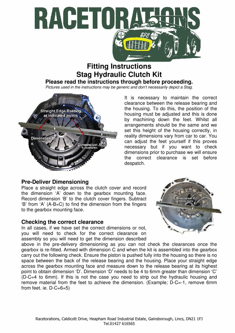
It is necessary to maintain the correct clearance between the release bearing and the housing. To do this, the position of the housing must be adjusted and this is done by machining down the feet. Whilst all arrangements should be the same and we set this height of the housing correctly, in reality dimensions vary from car to car. You can adjust the feet yourself if this proves necessary but if you want to check dimensions prior to purchase we will ensure the correct clearance is set before despatch.
Pre-Deliver Dimensioning Place a straight edge across the clutch cover and record the dimension ‘A’ down to the gearbox mounting face. Record dimension ‘B’ to the clutch cover fingers. Subtract ‘B’ from ‘A’ (A-B=C) to find the dimension from the fingers to the gearbox mounting face.
Checking the correct clearance In all cases, if we have set the correct dimensions or not, you will need to check for the correct clearance on assembly so you will need to get the dimension described above in the pre-delivery dimensioning as you can not check the clearances once the gearbox is re-fitted. Armed with dimension C and when the kit is assembled into the gearbox carry out the following check. Ensure the piston is pushed fully into the housing so there is no space between the back of the release bearing and the housing. Place your straight edge across the gearbox mounting face and measure down to the release bearing at its highest point to obtain dimension ‘D’. Dimension ‘D’ needs to be 4 to 6mm greater than dimension ‘C’ (D-C=4 to 6mm). If this is not the case you need to strip out the hydraulic housing and remove material from the feet to achieve the dimension. (Example; D-C=-1, remove 6mm from feet. ie. D-C+6=5)

Racetorations, Caldicott Drive, Heapham Road Industrial Estate, Gainsborough, Lincs, DN21 1FJ
Tel.01427 616565
Installing and setting the pedal stop To prevent the piston being pushed out of the housing, it is necessary to install a pedal stop. Take care you don’t press out the piston when bleeding the system by restricting the amount of pedal movement used when the system is closed up. When you come to do this, you may need some assistance to correctly set it. Inside the car, either side of the brake pedal are two nuts that hold the pedal plate in place. The bottom two nuts can be removed and the pedal stop installed on to the two bolts so that the adjusting screw is behind the clutch pedal. After bleeding the system, jack up the rear of the car and put it in gear. Have someone try to rotate the rear wheels as you slowly press in the clutch pedal. As soon as the wheels become free, hold the pedal position and wind out the adjusting nut so that it touches the back of the clutch pedal. Wind it back in two turns and lock it off in this position with the locknut.
Preparation 1. Drain clutch fluid using the slave
cylinder bleed nipple. 2. Remove the slave cylinder and pipe. 3. Remove the gearbox from the
car/engine. 4. Remove the release bearing and carrier. 5. Remove the cross shaft and fork. 6. Undo the four bolts and remove the front
nose. 7. Drill two 10mm holes in the casing as
indicated.
Fitting 1. Fit gasket, new nose, spacers and
adaptor piece. 2. Fit the hydraulic housing with a connection at the top and right on to the adaptor. 3. Check clearance as detailed above. 4. Connect the pipes to the housing and route the pipes to your drilled holes and fix with
the bulkhead nut outside the box. Note the position of the pipe at the top of the housing as this is the bleed. Use the P clip under one of the lay-shaft cover bolts to hold the feed pipe in a safe position clear of the release bearing.
5. Refit the gearbox to the car/engine. It is very important they are correctly aligned. 6. Connect the bleed adapter with nipple to the correct pipe outside the gearbox. 7. Connect the feed pipe to the outside of the gearbox and route the pipe neatly to the
master cylinder. 8. Screw the male/male adapter into the master cylinder and connect your feed pipe. 9. Install the pedal stop and then bleed the system. 10. Set the pedal stop as described above and test the clutch for correct operation.
Congratulations you now have a fully hydraulic clutch that will make driving a much easier and more pleasurable experience.