fisheye-lens-camera-based autonomous valet parking system
TRANSCRIPT
Fisheye-Lens-Camera-based Autonomous Valet Parking System
Young Gon Jo, Seok Hyeon Hong, Student Member, IEEE, Sung Soo Hwang, and Jeong Mok Ha, Member, IEEE
Abstract— This paper proposes an efficient autonomous valetparking system utilizing only cameras which are the mostwidely used sensor. To capture more information instanta-neously and respond rapidly to changes in the surroundingenvironment, fisheye cameras—which have a wider angle ofview compared to pinhole cameras—are used. Accordingly,visual simultaneous localization and mapping (SLAM) is usedto identify the layout of the parking lot and track the location ofthe vehicle. In addition, the input image frames are convertedinto around-viewmonitor (AVM) images to resolve the distortionof fisheye lens because the algorithm to detect edges are sup-posed to be applied to images taken with pinhole cameras. Theproposed system adopts a look-up table for real-time operationby minimizing the computational complexity encountered whenprocessing AVM images. The detection rate of each processand the success rate of autonomous parking were measured toevaluate performance. The experimental results confirm thatautonomous parking can be achieved using only visual sensors.
Index Terms— Autonomous Valet Parking System, AVM,Fisheye Lens, Look Up Table, SLAM, Template Matching
I. INTRODUCTION
AS self-driving technology continues to develop with theaim of absolutely unaided driving, advanced driverassistancesystems (ADAS) are likewise developing with the goal ofcomplete automation, which is the fifth level of automationdefined by the Society of Automotive Engineers(SAE).
Typical ADAS technology includes an autonomous park-ing system that aids drivers in precise and facile parking. De-veloped and presented jointly by German automotive multi-nationals Daimler AG and Robert Bosch, the autonomousvalet parking (AVP) system allows the vehicle to be parkedand recalled through a dedicated smartphone application. Inthe case of Hyundai’s and Kia’s automatic parking support
The work and experiment were supported by VADAS Co., Ltd.English language editing of this paper was supported by Editage(www.editage.co.kr). This work was supported by the National Programfor Excellence in Software at Handong Global University (2017-0-00130)fundeded by the Ministry of Science and ICT. (Young Gon Jo and SeokHyeon Hong contributed equally to this work.) (Corresponding author: SungSoo Hwang)
Young Gon Jo graduated from Handong University with a B.S. degreein computer and electrical engineering. He is now working at VADAS Co.,Ltd. (e-mail: [email protected]).
Seok Hyeon Hong is with the School of Computer Science and ElectricalEngineering, Handong University, Pohang 37554, South Korea (e-mail:[email protected]).
Sung Soo Hwang graduated from the Korea Advanced Institute of Scienceand Technology with a doctorate in electrical and electronic engineering. Heis now an associate professor at Handong University in the School of Com-puter Science and Electrical Engineering (e-mail: [email protected]).
Jeong Mok Ha graduated from Pohang University of Science and Tech-nology in Electrical Engineering. He is now the head of the algorithm teamat VADAS Co., Ltd. (e-mail: [email protected]).
systems, the speed and transmission are operated by thevehicle itself via ultrasonic sensors attached to the vehicle.
However, there are still many problems with existingautonomous parking systems. For instance, AVP systems(Daimler AG and Bosch) provide parking-space informationto self-parking vehicles by installing sensors in the parkinglot itself; these sensors are expensive to install and difficultto commercialize because the core of the system is inthe parking lot itself. In addition, in AVP, the driver mustfirst move the car directly into the parking lot and nearthe preferred parking bay, providing only simple functionssuch as basic reversing. On the other hand, self-parkingsystems using ultrasonic sensors are limited in that parkingis impossible when the lot is empty; these systems cannotobtain information about the vehicle’s vicinity when there isno parked vehicle for reference.
Therefore, in this study, we propose a automated AVP sys-tem utilizing efficient path-generation and driving strategiesin parking lots where lane and signal information are unclear.Essentially, the system improves general functionality at alower cost. For instance, should the driver disembark at anylocation and run the proposed system, the car will navigateinto the parking lot independently; if an empty bay is located,the car will park unaided. The novel system uses neither lightdetection and ranging (LiDAR) sensors that otherwise hindercommercialization due to expensive unit prices [1], nor GPSsensors that cannot obtain information inside the parking lotexcept location information [2], nor ultrasonic sensors thatonly measure the distance from nearby objects, and are henceless accurate. Instead, similar to the method proposed in [3],this system performs autonomous parking using a fisheyecamera and a sensor that accurately identifies information inthe indoor parking lot while having an affordable unit price.
II. PROPOSED DESIGNA. Overall System Architecture
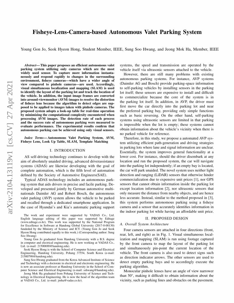
Four camera sensors are attached in four directions (front,rear, left, and right) as in Fig. 1. Visual simultaneous local-ization and mapping (SLAM) is run using footage capturedby the front camera to map the layout of the parking lotand simultaneously pin-point the current location of thevehicle. The front camera is also used to detect signs suchas direction indicator arrows. The other sensors are used todetect empty parking bays and to accordingly execute theparking algorithm.
Monocular pinhole lenses have an angle of view narrowerthan 50°, making it difficult to obtain information about thevicinity, such as parking lines and obstacles on the pavement.
arX
iv:2
104.
1311
9v1
[cs
.CV
] 2
7 A
pr 2
021
In this regard, the proposed system uses fisheye lenses withan angle of view of 180° to capture more information throughthe cameras.
Fig. 1. Sensor layout used in the system
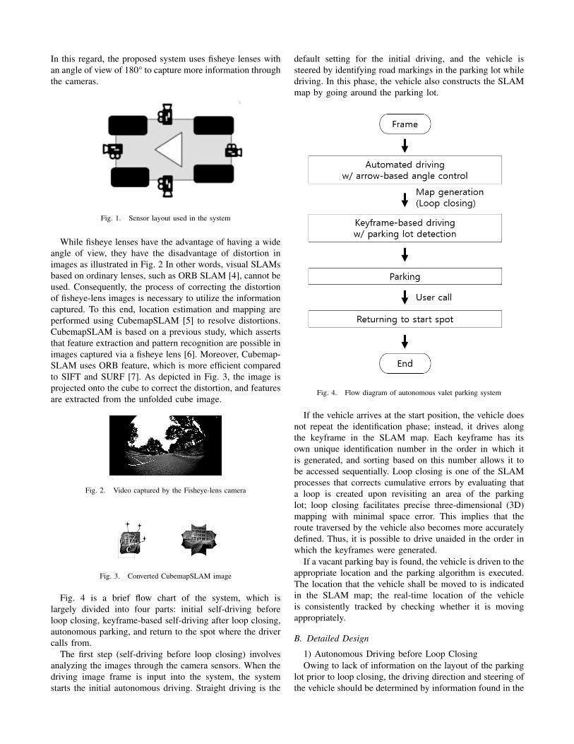
While fisheye lenses have the advantage of having a wideangle of view, they have the disadvantage of distortion inimages as illustrated in Fig. 2 In other words, visual SLAMsbased on ordinary lenses, such as ORB SLAM [4], cannot beused. Consequently, the process of correcting the distortionof fisheye-lens images is necessary to utilize the informationcaptured. To this end, location estimation and mapping areperformed using CubemapSLAM [5] to resolve distortions.CubemapSLAM is based on a previous study, which assertsthat feature extraction and pattern recognition are possible inimages captured via a fisheye lens [6]. Moreover, Cubemap-SLAM uses ORB feature, which is more efficient comparedto SIFT and SURF [7]. As depicted in Fig. 3, the image isprojected onto the cube to correct the distortion, and featuresare extracted from the unfolded cube image.
Fig. 2. Video captured by the Fisheye-lens camera
Fig. 3. Converted CubemapSLAM image
Fig. 4 is a brief flow chart of the system, which islargely divided into four parts: initial self-driving beforeloop closing, keyframe-based self-driving after loop closing,autonomous parking, and return to the spot where the drivercalls from.
The first step (self-driving before loop closing) involvesanalyzing the images through the camera sensors. When thedriving image frame is input into the system, the systemstarts the initial autonomous driving. Straight driving is the
default setting for the initial driving, and the vehicle issteered by identifying road markings in the parking lot whiledriving. In this phase, the vehicle also constructs the SLAMmap by going around the parking lot.
Fig. 4. Flow diagram of autonomous valet parking system
If the vehicle arrives at the start position, the vehicle doesnot repeat the identification phase; instead, it drives alongthe keyframe in the SLAM map. Each keyframe has itsown unique identification number in the order in which itis generated, and sorting based on this number allows it tobe accessed sequentially. Loop closing is one of the SLAMprocesses that corrects cumulative errors by evaluating thata loop is created upon revisiting an area of the parkinglot; loop closing facilitates precise three-dimensional (3D)mapping with minimal space error. This implies that theroute traversed by the vehicle also becomes more accuratelydefined. Thus, it is possible to drive unaided in the order inwhich the keyframes were generated.
If a vacant parking bay is found, the vehicle is driven to theappropriate location and the parking algorithm is executed.The location that the vehicle shall be moved to is indicatedin the SLAM map; the real-time location of the vehicleis consistently tracked by checking whether it is movingappropriately.
B. Detailed Design
1) Autonomous Driving before Loop ClosingOwing to lack of information on the layout of the parking
lot prior to loop closing, the driving direction and steering ofthe vehicle should be determined by information found in the
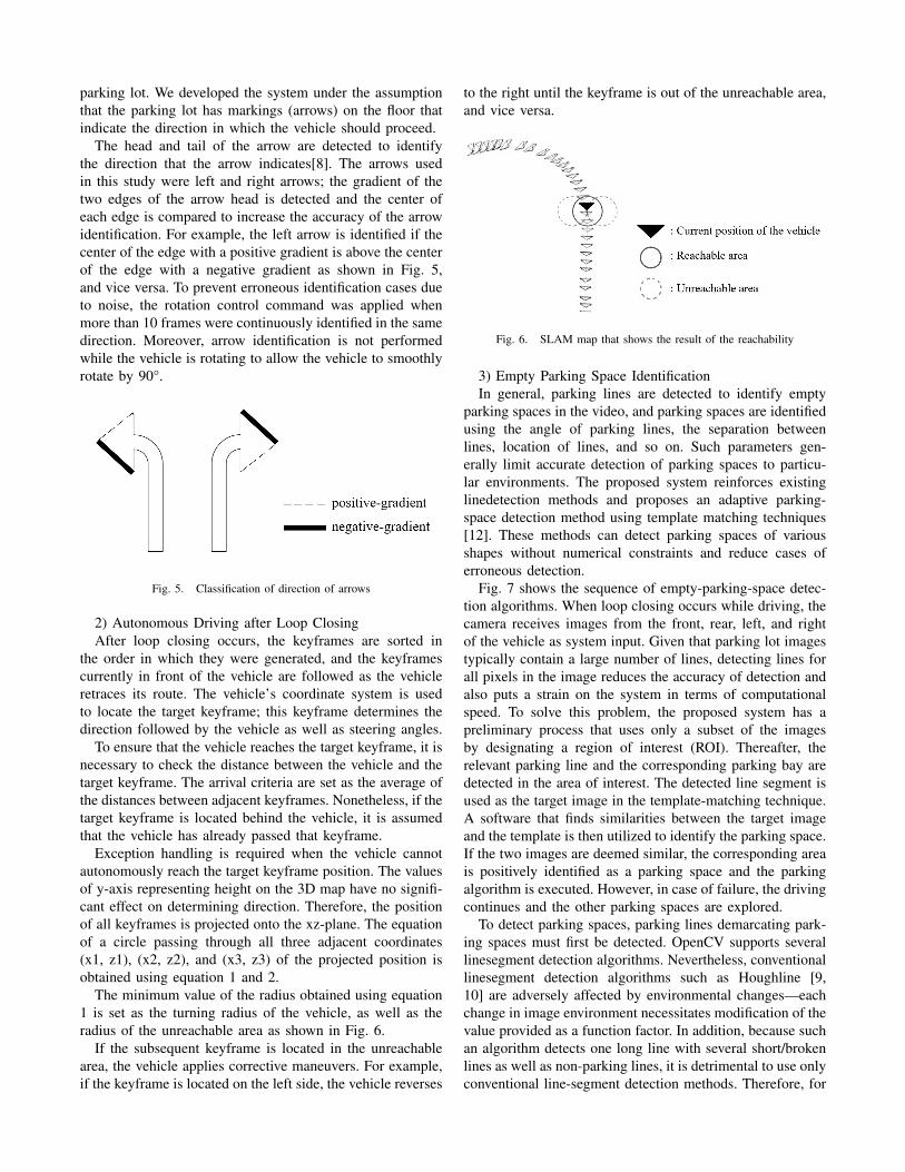
parking lot. We developed the system under the assumptionthat the parking lot has markings (arrows) on the floor thatindicate the direction in which the vehicle should proceed.
The head and tail of the arrow are detected to identifythe direction that the arrow indicates[8]. The arrows usedin this study were left and right arrows; the gradient of thetwo edges of the arrow head is detected and the center ofeach edge is compared to increase the accuracy of the arrowidentification. For example, the left arrow is identified if thecenter of the edge with a positive gradient is above the centerof the edge with a negative gradient as shown in Fig. 5,and vice versa. To prevent erroneous identification cases dueto noise, the rotation control command was applied whenmore than 10 frames were continuously identified in the samedirection. Moreover, arrow identification is not performedwhile the vehicle is rotating to allow the vehicle to smoothlyrotate by 90°.
Fig. 5. Classification of direction of arrows
2) Autonomous Driving after Loop ClosingAfter loop closing occurs, the keyframes are sorted in
the order in which they were generated, and the keyframescurrently in front of the vehicle are followed as the vehicleretraces its route. The vehicle’s coordinate system is usedto locate the target keyframe; this keyframe determines thedirection followed by the vehicle as well as steering angles.
To ensure that the vehicle reaches the target keyframe, it isnecessary to check the distance between the vehicle and thetarget keyframe. The arrival criteria are set as the average ofthe distances between adjacent keyframes. Nonetheless, if thetarget keyframe is located behind the vehicle, it is assumedthat the vehicle has already passed that keyframe.
Exception handling is required when the vehicle cannotautonomously reach the target keyframe position. The valuesof y-axis representing height on the 3D map have no signifi-cant effect on determining direction. Therefore, the positionof all keyframes is projected onto the xz-plane. The equationof a circle passing through all three adjacent coordinates(x1, z1), (x2, z2), and (x3, z3) of the projected position isobtained using equation 1 and 2.
The minimum value of the radius obtained using equation1 is set as the turning radius of the vehicle, as well as theradius of the unreachable area as shown in Fig. 6.
If the subsequent keyframe is located in the unreachablearea, the vehicle applies corrective maneuvers. For example,if the keyframe is located on the left side, the vehicle reverses
to the right until the keyframe is out of the unreachable area,and vice versa.
Fig. 6. SLAM map that shows the result of the reachability
3) Empty Parking Space IdentificationIn general, parking lines are detected to identify empty
parking spaces in the video, and parking spaces are identifiedusing the angle of parking lines, the separation betweenlines, location of lines, and so on. Such parameters gen-erally limit accurate detection of parking spaces to particu-lar environments. The proposed system reinforces existinglinedetection methods and proposes an adaptive parking-space detection method using template matching techniques[12]. These methods can detect parking spaces of variousshapes without numerical constraints and reduce cases oferroneous detection.
Fig. 7 shows the sequence of empty-parking-space detec-tion algorithms. When loop closing occurs while driving, thecamera receives images from the front, rear, left, and rightof the vehicle as system input. Given that parking lot imagestypically contain a large number of lines, detecting lines forall pixels in the image reduces the accuracy of detection andalso puts a strain on the system in terms of computationalspeed. To solve this problem, the proposed system has apreliminary process that uses only a subset of the imagesby designating a region of interest (ROI). Thereafter, therelevant parking line and the corresponding parking bay aredetected in the area of interest. The detected line segment isused as the target image in the template-matching technique.A software that finds similarities between the target imageand the template is then utilized to identify the parking space.If the two images are deemed similar, the corresponding areais positively identified as a parking space and the parkingalgorithm is executed. However, in case of failure, the drivingcontinues and the other parking spaces are explored.
To detect parking spaces, parking lines demarcating park-ing spaces must first be detected. OpenCV supports severallinesegment detection algorithms. Nevertheless, conventionallinesegment detection algorithms such as Houghline [9,10] are adversely affected by environmental changes—eachchange in image environment necessitates modification of thevalue provided as a function factor. In addition, because suchan algorithm detects one long line with several short/brokenlines as well as non-parking lines, it is detrimental to use onlyconventional line-segment detection methods. Therefore, for
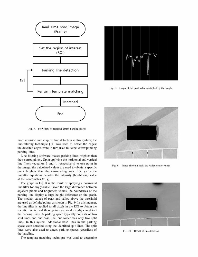
Fig. 7. Flowchart of detecting empty parking spaces
more accurate and adaptive line detection in this system, theline-filtering technique [11] was used to detect the edges;the detected edges were in turn used to detect correspondingparking lines.
Line filtering software makes parking lines brighter thantheir surroundings. Upon applying the horizontal and verticalline filters (equation 3 and 4, respectively) to one point inthe image, the calculated values are used to obtain a specificpoint brighter than the surrounding area. L(x; y) in thelinefilter equations denotes the intensity (brightness) valueat the coordinates (x, y).
The graph in Fig. 8 is the result of applying a horizontalline filter for any y-value. Given the large difference betweenadjacent pixels and brightness values, the boundaries of theparking line display a large height difference on the graph.The median values of peak and valley above the thresholdare used as definite points as shown in Fig. 9. In this manner,the line filter is applied to all pixels in the ROI to obtain thespecific points, and these points are used as edges to detectthe parking lines. A parking space typically consists of twosplit lines and one base line, but sometimes only two splitlines. In this system, additional base lines in the parkingspace were detected using the identified split lines. The splitlines were also used to detect parking spaces regardless ofthe baseline.
The template-matching technique was used to determine
Fig. 8. Graph of the pixel value multiplied by the weight
Fig. 9. Image showing peak and valley center values
Fig. 10. Result of line detection
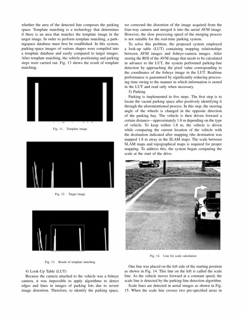
whether the area of the detected line composes the parkingspace. Template matching is a technology that determinesif there is an area that matches the template image in thetarget image. In order to perform template matching, a park-ingspace database must first be established. In this system,parking-space images of various shapes were compiled intoa template database and easily compared to target images.After template matching, the vehicle positioning and parkingsteps were carried out. Fig. 13 shows the result of templatematching.
Fig. 11. Template image
Fig. 12. Target image
Fig. 13. Result of template matching
4) Look-Up Table (LUT)Because the camera attached to the vehicle was a fisheye
camera, it was impossible to apply algorithms to detectedges and lines in images of parking lots due to severeimage distortion. Therefore, to identify the parking space,
we corrected the distortion of the image acquired from thefour-way camera and merged it into the aerial AVM image.However, the slow processing speed of the merging processis not suitable for the real-time parking system.
To solve this problem, the proposed system employeda look-up table (LUT) containing mapping relationshipsbetween AVM images and fisheye-camera images. Afterstoring the ROI of the AVM image that needs to be calculatedin advance to the LUT, the system performed parking-linedetection by approaching the pixel value corresponding tothe coordinates of the fisheye image in the LUT. Realtimeperformance is guaranteed by significantly reducing process-ing time owing to the manner in which information is storedin the LUT and read only when necessary.
5) ParkingParking is implemented in five steps. The first step is to
locate the vacant parking space after positively identifying itthrough the aforementioned process. In this step, the steeringangle of the wheels is changed in the opposite directionof the parking bay. The vehicle is then driven forward acertain distance—approximately 1.8 m depending on the typeof vehicle. To keep within 1.8 m, the vehicle is drivenwhile comparing the current location of the vehicle withthe destination indicated after mapping (the destination wasmapped 1.8 m away in the SLAM map). The scale betweenSLAM maps and topographical maps is required for propermapping. To address this, the system began computing thescale at the start of the drive.
Fig. 14. Line for scale calculation
One line was placed on the left side of the starting positionas shown in Fig. 14. This line on the left is called the scaleline. As the vehicle moves forward at a constant speed, thescale line is detected by the parking-line detection algorithm.
Scale lines are detected in aerial images as shown in Fig.15. When the scale line crosses two pre-specified areas in
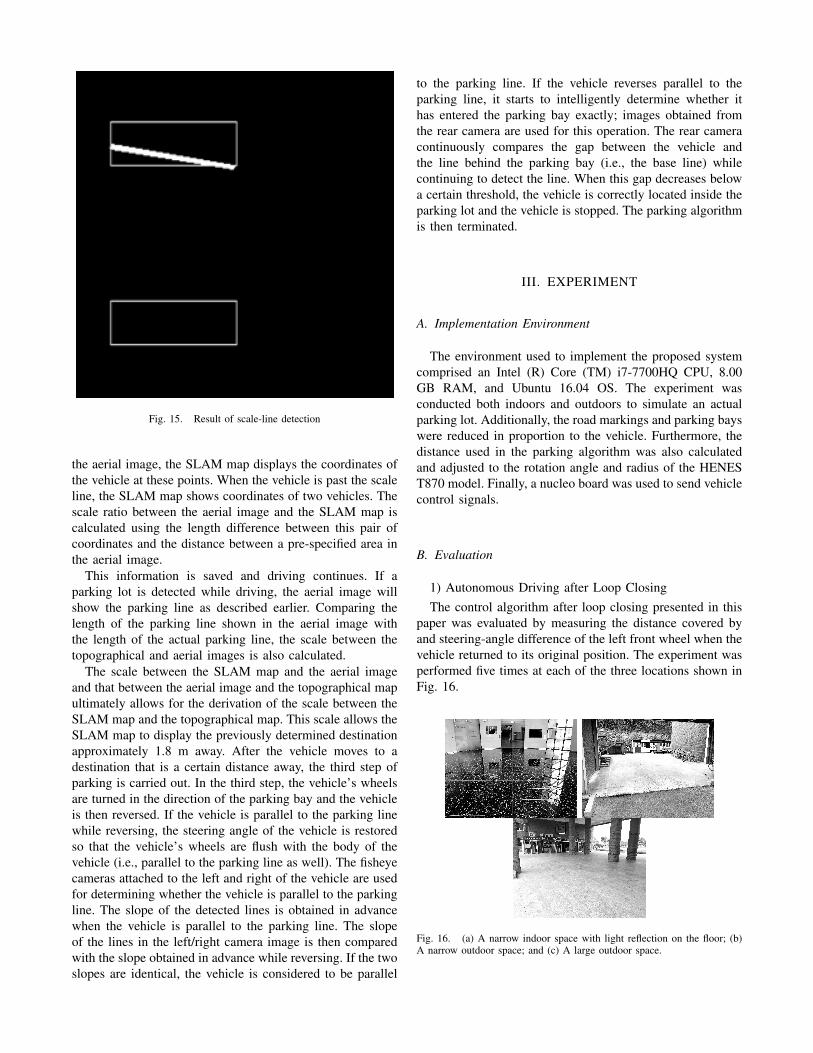
Fig. 15. Result of scale-line detection
the aerial image, the SLAM map displays the coordinates ofthe vehicle at these points. When the vehicle is past the scaleline, the SLAM map shows coordinates of two vehicles. Thescale ratio between the aerial image and the SLAM map iscalculated using the length difference between this pair ofcoordinates and the distance between a pre-specified area inthe aerial image.
This information is saved and driving continues. If aparking lot is detected while driving, the aerial image willshow the parking line as described earlier. Comparing thelength of the parking line shown in the aerial image withthe length of the actual parking line, the scale between thetopographical and aerial images is also calculated.
The scale between the SLAM map and the aerial imageand that between the aerial image and the topographical mapultimately allows for the derivation of the scale between theSLAM map and the topographical map. This scale allows theSLAM map to display the previously determined destinationapproximately 1.8 m away. After the vehicle moves to adestination that is a certain distance away, the third step ofparking is carried out. In the third step, the vehicle’s wheelsare turned in the direction of the parking bay and the vehicleis then reversed. If the vehicle is parallel to the parking linewhile reversing, the steering angle of the vehicle is restoredso that the vehicle’s wheels are flush with the body of thevehicle (i.e., parallel to the parking line as well). The fisheyecameras attached to the left and right of the vehicle are usedfor determining whether the vehicle is parallel to the parkingline. The slope of the detected lines is obtained in advancewhen the vehicle is parallel to the parking line. The slopeof the lines in the left/right camera image is then comparedwith the slope obtained in advance while reversing. If the twoslopes are identical, the vehicle is considered to be parallel
to the parking line. If the vehicle reverses parallel to theparking line, it starts to intelligently determine whether ithas entered the parking bay exactly; images obtained fromthe rear camera are used for this operation. The rear cameracontinuously compares the gap between the vehicle andthe line behind the parking bay (i.e., the base line) whilecontinuing to detect the line. When this gap decreases belowa certain threshold, the vehicle is correctly located inside theparking lot and the vehicle is stopped. The parking algorithmis then terminated.
III. EXPERIMENT
A. Implementation Environment
The environment used to implement the proposed systemcomprised an Intel (R) Core (TM) i7-7700HQ CPU, 8.00GB RAM, and Ubuntu 16.04 OS. The experiment wasconducted both indoors and outdoors to simulate an actualparking lot. Additionally, the road markings and parking bayswere reduced in proportion to the vehicle. Furthermore, thedistance used in the parking algorithm was also calculatedand adjusted to the rotation angle and radius of the HENEST870 model. Finally, a nucleo board was used to send vehiclecontrol signals.
B. Evaluation
1) Autonomous Driving after Loop ClosingThe control algorithm after loop closing presented in this
paper was evaluated by measuring the distance covered byand steering-angle difference of the left front wheel when thevehicle returned to its original position. The experiment wasperformed five times at each of the three locations shown inFig. 16.
Fig. 16. (a) A narrow indoor space with light reflection on the floor; (b)A narrow outdoor space; and (c) A large outdoor space.
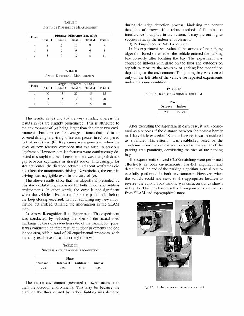
TABLE IDISTANCE DIFFERENCE MEASUREMENT
Place Distance Difference (cm, ±0.5)Trial 1 Trial 2 Trial 3 Trial 4 Trial 5
a 8 5 11 8 5
b 8 5 6 6 8
c 5 7 12 8 11
TABLE IIANGLE DIFFERENCE MEASUREMENT
Place Angle Difference (°, ±2.5)Trial 1 Trial 2 Trial 3 Trial 4 Trial 5
a 10 15 20 15 15
b 15 15 10 15 20
c 15 10 15 15 10
The results in (a) and (b) are very similar, whereas theresults in (c) are slightly pronounced. This is attributed tothe environment of (c) being larger than the other two envi-ronments. Furthermore, the average distance that had to becovered driving in a straight line was greater in (c) comparedto that in (a) and (b). Keyframes were generated when thelevel of new features exceeded that exhibited in previouskeyframes. However, similar features were continuously de-tected in straight routes. Therefore, there was a large distancegap between keyframes in straight routes. Interestingly, forstraight routes, the distance between adjacent keyframes didnot affect the autonomous driving. Nevertheless, the error indriving was negligible even in the case of (c).
The above results show that the algorithms presented bythis study exhibit high accuracy for both indoor and outdoorenvironments. In other words, the error is not significantwhen the vehicle drives along the same path it did beforethe loop closing occurred, without capturing any new infor-mation but instead utilizing the information in the SLAMmap.
2) Arrow Recognition Rate Experiment The experimentwas conducted by reducing the size of the actual roadmarkings by the same reduction ratio of the parking lot space.It was conducted on three regular outdoor pavements and oneindoor area, with a total of 20 experimental processes, eachmutually exclusive for a left or right arrow.
TABLE IIISUCCESS RATE OF ARROW RECOGNITION
PlaceOutdoor 1 Outdoor 2 Outdoor 3 Indoor
85% 80% 90% 70%
The indoor environment presented a lower success ratethan the outdoor environments. This may be because theglare on the floor caused by indoor lighting was detected
during the edge detection process, hindering the correctdetection of arrows. If a robust method of illuminationinterference is applied in the system, it may present highersuccess rates in the indoor environment.
3) Parking Success Rate ExperimentIn this experiment, we evaluated the success of the parking
algorithm based on whether the vehicle entered the parkingbay correctly after locating the bay. The experiment wasconducted indoors with glare on the floor and outdoors onasphalt to measure the accuracy of parking-line recognitiondepending on the environment. The parking bay was locatedonly on the left side of the vehicle for repeated experimentsunder the same conditions.
TABLE IVSUCCESS RATE OF PARKING ALGORITHM
PlaceOutdoor Indoor
75% 62.5%
After executing the algorithm in each case, it was consid-ered as a success if the distance between the nearest borderand the vehicle exceeded 18 cm; otherwise, it was consideredas a failure. This criterion was established based on thecondition when the vehicle was located in the center of theparking area parallelly, considering the size of the parkingbay.
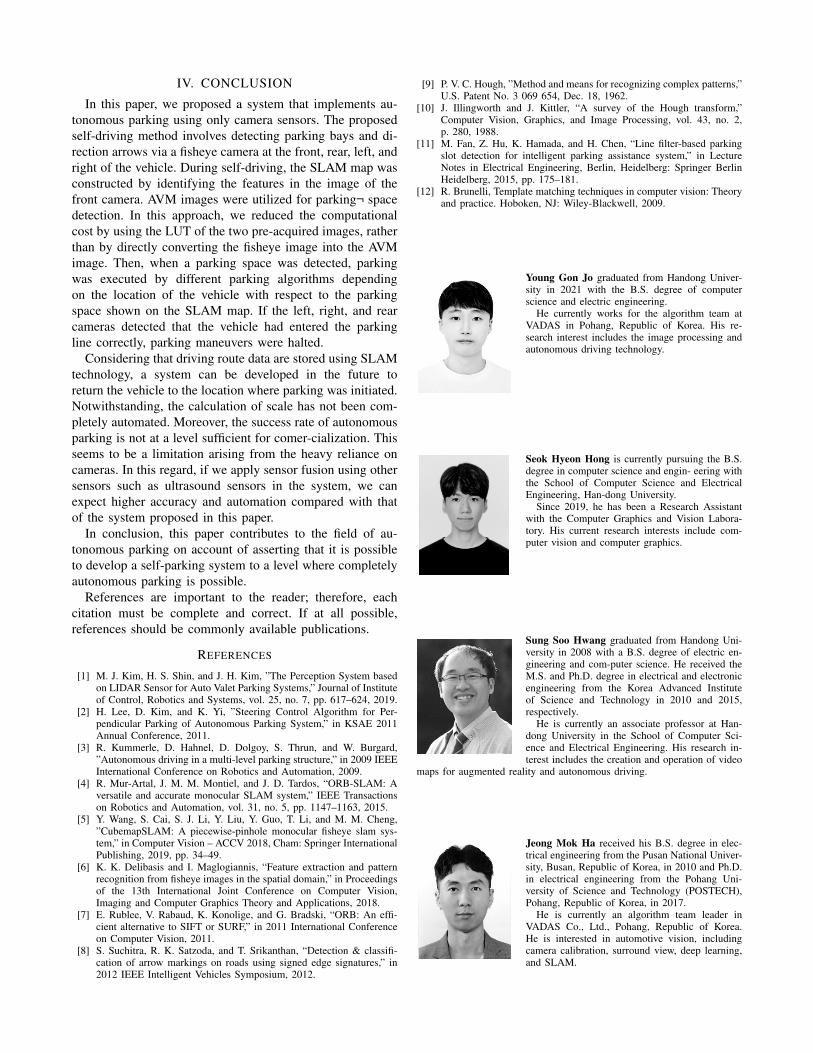
The experiments showed 62.575matching were performedeffectively in both environments. Parallel alignment anddetection of the end of the parking algorithm were also suc-cessfully performed in both environments. However, whenthe vehicle could not move to the appropriate location toreverse, the autonomous parking was unsuccessful as shownin Fig. 17. This may have resulted from poor scale estimationfrom SLAM and topographical maps.
Fig. 17. Failure cases in indoor environment
IV. CONCLUSION
In this paper, we proposed a system that implements au-tonomous parking using only camera sensors. The proposedself-driving method involves detecting parking bays and di-rection arrows via a fisheye camera at the front, rear, left, andright of the vehicle. During self-driving, the SLAM map wasconstructed by identifying the features in the image of thefront camera. AVM images were utilized for parking¬ spacedetection. In this approach, we reduced the computationalcost by using the LUT of the two pre-acquired images, ratherthan by directly converting the fisheye image into the AVMimage. Then, when a parking space was detected, parkingwas executed by different parking algorithms dependingon the location of the vehicle with respect to the parkingspace shown on the SLAM map. If the left, right, and rearcameras detected that the vehicle had entered the parkingline correctly, parking maneuvers were halted.
Considering that driving route data are stored using SLAMtechnology, a system can be developed in the future toreturn the vehicle to the location where parking was initiated.Notwithstanding, the calculation of scale has not been com-pletely automated. Moreover, the success rate of autonomousparking is not at a level sufficient for comer-cialization. Thisseems to be a limitation arising from the heavy reliance oncameras. In this regard, if we apply sensor fusion using othersensors such as ultrasound sensors in the system, we canexpect higher accuracy and automation compared with thatof the system proposed in this paper.
In conclusion, this paper contributes to the field of au-tonomous parking on account of asserting that it is possibleto develop a self-parking system to a level where completelyautonomous parking is possible.
References are important to the reader; therefore, eachcitation must be complete and correct. If at all possible,references should be commonly available publications.
REFERENCES
[1] M. J. Kim, H. S. Shin, and J. H. Kim, ”The Perception System basedon LIDAR Sensor for Auto Valet Parking Systems,” Journal of Instituteof Control, Robotics and Systems, vol. 25, no. 7, pp. 617–624, 2019.
[2] H. Lee, D. Kim, and K. Yi, ”Steering Control Algorithm for Per-pendicular Parking of Autonomous Parking System,” in KSAE 2011Annual Conference, 2011.
[3] R. Kummerle, D. Hahnel, D. Dolgoy, S. Thrun, and W. Burgard,”Autonomous driving in a multi-level parking structure,” in 2009 IEEEInternational Conference on Robotics and Automation, 2009.
[4] R. Mur-Artal, J. M. M. Montiel, and J. D. Tardos, “ORB-SLAM: Aversatile and accurate monocular SLAM system,” IEEE Transactionson Robotics and Automation, vol. 31, no. 5, pp. 1147–1163, 2015.
[5] Y. Wang, S. Cai, S. J. Li, Y. Liu, Y. Guo, T. Li, and M. M. Cheng,”CubemapSLAM: A piecewise-pinhole monocular fisheye slam sys-tem,” in Computer Vision – ACCV 2018, Cham: Springer InternationalPublishing, 2019, pp. 34–49.
[6] K. K. Delibasis and I. Maglogiannis, “Feature extraction and patternrecognition from fisheye images in the spatial domain,” in Proceedingsof the 13th International Joint Conference on Computer Vision,Imaging and Computer Graphics Theory and Applications, 2018.
[7] E. Rublee, V. Rabaud, K. Konolige, and G. Bradski, “ORB: An effi-cient alternative to SIFT or SURF,” in 2011 International Conferenceon Computer Vision, 2011.
[8] S. Suchitra, R. K. Satzoda, and T. Srikanthan, “Detection & classifi-cation of arrow markings on roads using signed edge signatures,” in2012 IEEE Intelligent Vehicles Symposium, 2012.
[9] P. V. C. Hough, ”Method and means for recognizing complex patterns,”U.S. Patent No. 3 069 654, Dec. 18, 1962.
[10] J. Illingworth and J. Kittler, “A survey of the Hough transform,”Computer Vision, Graphics, and Image Processing, vol. 43, no. 2,p. 280, 1988.
[11] M. Fan, Z. Hu, K. Hamada, and H. Chen, “Line filter-based parkingslot detection for intelligent parking assistance system,” in LectureNotes in Electrical Engineering, Berlin, Heidelberg: Springer BerlinHeidelberg, 2015, pp. 175–181.
[12] R. Brunelli, Template matching techniques in computer vision: Theoryand practice. Hoboken, NJ: Wiley-Blackwell, 2009.
Young Gon Jo graduated from Handong Univer-sity in 2021 with the B.S. degree of computerscience and electric engineering.
He currently works for the algorithm team atVADAS in Pohang, Republic of Korea. His re-search interest includes the image processing andautonomous driving technology.
Seok Hyeon Hong is currently pursuing the B.S.degree in computer science and engin- eering withthe School of Computer Science and ElectricalEngineering, Han-dong University.
Since 2019, he has been a Research Assistantwith the Computer Graphics and Vision Labora-tory. His current research interests include com-puter vision and computer graphics.
Sung Soo Hwang graduated from Handong Uni-versity in 2008 with a B.S. degree of electric en-gineering and com-puter science. He received theM.S. and Ph.D. degree in electrical and electronicengineering from the Korea Advanced Instituteof Science and Technology in 2010 and 2015,respectively.
He is currently an associate professor at Han-dong University in the School of Computer Sci-ence and Electrical Engineering. His research in-terest includes the creation and operation of video
maps for augmented reality and autonomous driving.
Jeong Mok Ha received his B.S. degree in elec-trical engineering from the Pusan National Univer-sity, Busan, Republic of Korea, in 2010 and Ph.D.in electrical engineering from the Pohang Uni-versity of Science and Technology (POSTECH),Pohang, Republic of Korea, in 2017.
He is currently an algorithm team leader inVADAS Co., Ltd., Pohang, Republic of Korea.He is interested in automotive vision, includingcamera calibration, surround view, deep learning,and SLAM.