fisherr 2052 diaphragm rotary actuator - applied … fisherr 2052 diaphragm rotary actuator fisher...
TRANSCRIPT

www.Fisher.com
Fisherr 2052 Diaphragm Rotary ActuatorFisher 2052 spring-and-diaphragm rotary actuators(see figures 1 and 2) are used on rotary-shaft valvebodies for throttling or on-off applications. The 2052may be used for throttling service with a positioner, orit may be used for on-off service without a positioner.The 2052 has an ISO 5211 mating interface thatallows installation to non-Fisher valves. Refer toseparate bulletins for valve and positionerinformation.
Contents2052 Actuator Specifications and Materialsof Construction 2. . . . . . . . . . . . . . . . . . . . . . . . .
Features 3. . . . . . . . . . . . . . . . . . . . . . . . . . . . . . . . .Options 3. . . . . . . . . . . . . . . . . . . . . . . . . . . . . . . . . .Tables
Actuator and Shaft Size Availability 5. . . . .Torque versus Actuator Size 5. . . . . . . . . . .Pressure Connections 5. . . . . . . . . . . . . . . .Dimensions 6. . . . . . . . . . . . . . . . . . . . . . . . .Mounting Style 10. . . . . . . . . . . . . . . . . . . . . .
W9425--2
Figure 1. Fisher Control-Diskt Valve with 2052 Actuator and DVC6200 Digital Valve Controller
Product Bulletin61.1:2052D103295X012August 2011 2052 Actuator

2052 ActuatorProduct Bulletin
61.1:2052August 2011
2
2052 Actuator Specifications and Materials of ConstructionSee tables 1 and 2.
Table 1. Fisher 2052 Actuator SpecificationsSpecifications
Actuator Mounting Connections Splined shaft connection, ISO 5211 actuator-to-bracket connectionSize 1: F07, Size 2: F10, Size 3: F14
Actuator Sizes See table 3
Operating Pressure(1) See table 5
Maximum Diaphragm CasingPressure
Size 1, 2, and 3 Actuators: 5 barg (73 psig)
Pressure Connection See table 4Torque Output See table 5Actuator TemperatureCapabilities(1)
--45 to 80_C (--50 to 176_F)
Operation Field reversible between PDTC and PDTO; right- and left-hand mounting, any angle oforientation
Approximate WeightSize 1: 22.2 kg (49 lb)Size 2: 54.4 kg (120 lb)Size 3: 113 kg (250 lb)
Controller/Positioners Available DVC2000, DVC6020, DVC6030, DVC6200, 3610J, 3620J, 4190, C1Accessories Available 846, 646, 2625, and 67C Series, switches, i2P--100, VBL, DXP, GOt
Handwheel Top-mounted handwheel: Optional on Size 1 and 2 actuators onlyDeclutchable handwheel: Optional on Size 1, 2, and 3 actuators
Operational Lockout Available for customer-supplied padlock to lock the actuator in the spring-fail position1. The pressure/temperature limits in this bulletin should not be exceeded.
Table 2. Materials of ConstructionComponent Material
Top Casing Steel
Housing Cast Iron
Diaphragm Nitrile and nylon standard
Lever Ductile iron
Diaphragm Plate Cast iron
OPTIONAL TOP--MOUNTED HANDWHEEL ASSEMBLY
Component Material
Handwheel Cast iron
Handwheel Stem Aluminum--Bronze
Top Casing Assembly Steel
O--ring Nitrile
Pusher Plate Steel
2052 ActuatorProduct Bulletin61.1:2052August 2011
3
Features
D Compact design, smaller actuators—Ensures reduced valve/actuator envelopedimensions leading to greater mounting versatility forboth skids and process plants, where space is at apremium.
D Compatible with DVC2000, DVC6200, andDVC6000 digital valve controllers; and 3610J and3620J positioners— The new actuator allowslinkage-less feedback, via a contact-less magneticarray, from the lever to the end-mounted DVC2000.Integral window mounting of the DVC6200,DVC6000, 3610J, and 3620J is also available.
D Clamped lever to reduce lost motion— Theclamping of the lever onto a splined valve shaft,coupled with the single pivot linkage, reduces lostmotion between the actuator and the valve. Thetypical cumulative deadband for a Fisher rotarycontrol valve assembly results in 0.5% or lessvariability.
D No bench set required— The new nestedspring design requires no bench set. This alsosimplifies the actuator selection process, see table 3.
D ISO 5211 mounting with optional insert—The actuator can now be mounted directly ontonon-spline shafts, such as Square and Double D.This allows the actuator, with its enhanced control,to mount on a wider range of valves conforming toISO 5211.
D Adjustable travel stops standard withoptional lockout feature— Provides the ability toadjust or change the travel range without removingthe actuator or the addition of extra parts. Theoptional lockout feature locks the lever in thespring-fail position.
D Fail-safe mechanism contains noaluminum— All parts in the fail-safe mechanism(made of steel, cast iron, and ductile iron) ensure theactuator will maintain safety integrity in the event ofa fire.
D Powder paint as standard— The EmersonProcess Managementt powder paint finish offers anexcellent corrosion-resistant finish to all externalsteel and cast iron parts.
D NAMUR VDE/VDI 3845 for accessorymounting— Meeting the global standard ensurescompatibility for most accessories, enabling quickand easy mounting.
D Field reversible, right- or left-handmounting— The actuator/valve assembly action canbe converted from push-down-to-open topush-down-to-close, or vice-versa, without additionalparts.
D Declutchable and top-mountedhandwheels— Available (except top-mounted notavailable for size 3 actuator).
OptionsTop-Mounted Handwheel: For infrequent use as amanual actuator (see figure 3). For repeated or dailymanual operation, the unit should be equipped witha declutchable handwheel actuator.
Declutchable Handwheel Actuator: Anend-mounted manual actuator can be used toprovide on-site control and to provide overridecapabilities. See bulletin 61.8:1078 for handwheelactuator specifications.
Limit Switches: J Micro-Switch or NAMCOswitches for one or two single-pole, double-throwcontacts, or J GO proximity switches for one or twosingle-pole, double-throw contacts are available. Seeseparate bulletins for limit switch information.
Position Indicating Switch: TopWorxt DXPM21GNEB switch for one through six single pole,double throw switch contacts are available. Seeseparate bulletin for position indicating switchinformation.
Positioner: For precise positioning of the valvecontrol element, the actuator should be equippedwith a positioner. For additional information, contactyour Emerson Process Management sales officewith complete service conditions.
Actuator Locking Mechanism: An actuator lockingmechanism is available, which can be used to keepthe actuator in a locked position (the same as thespring-fail position) during maintenance. The padlockis customer supplied.

2052 ActuatorProduct Bulletin
61.1:2052August 2011
4
W9421-1
Figure 2. Fisher 2052 Assembly
2052 ActuatorProduct Bulletin61.1:2052August 2011
5
W9484
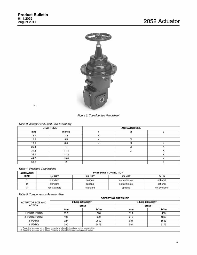
Figure 3. Top-Mounted Handwheel
Table 3. Actuator and Shaft Size AvailabilitySHAFT SIZE ACTUATOR SIZE
mm Inches 1 2 3
12.7 1/2 X
15.9 5/8 X X
19.1 3/4 X X X
25.4 1 X X
31.8 1-1/4 X X
38.1 1-1/2 X
44.5 1-3/4 X
50.8 2 X
Table 4. Pressure Connections
ACTUATORSIZE
PRESSURE CONNECTION
1/4 NPT 1/2 NPT 3/4 NPT G 1/4
1 standard optional not available optional
2 standard optional not available optional
3 not available standard optional not available
Table 5. Torque versus Actuator Size
ACTUATOR SIZE ANDACTION
OPERATING PRESSURE
2 barg (29 psig)(1) 4 barg (58 psig)(2)
Torque Torque
NSm lbfSin NSm lbfSin
1 (PDTO, PDTC) 25.5 226 51.2 453
2 (PDTO, PDTC) 105 930 210 1860
3 (PDTO) 327 2890 631 5583
3 (PDTC) 280 2479 584 51731. Operating pressure up to 3 barg (44 psig) is allowable for single spring construction.2. Operating pressure up to 5 barg (73 psig) is allowable for dual spring construction.
2052 ActuatorProduct Bulletin
61.1:2052August 2011
6
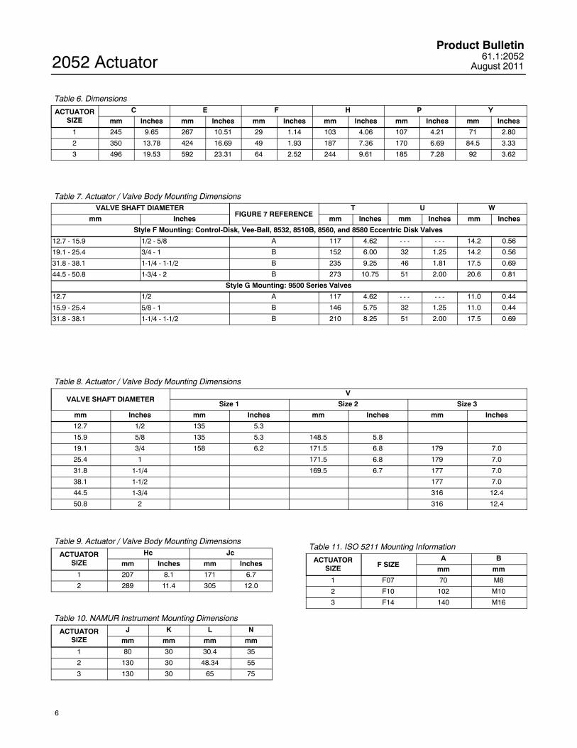
Table 6. Dimensions
ACTUATORSIZE
C E F H P Y
mm Inches mm Inches mm Inches mm Inches mm Inches mm Inches
1 245 9.65 267 10.51 29 1.14 103 4.06 107 4.21 71 2.80
2 350 13.78 424 16.69 49 1.93 187 7.36 170 6.69 84.5 3.33
3 496 19.53 592 23.31 64 2.52 244 9.61 185 7.28 92 3.62
Table 7. Actuator / Valve Body Mounting DimensionsVALVE SHAFT DIAMETER
FIGURE 7 REFERENCET U W
mm Inches mm Inches mm Inches mm Inches
Style F Mounting: Control-Disk, Vee-Ball, 8532, 8510B, 8560, and 8580 Eccentric Disk Valves
12.7 - 15.9 1/2 - 5/8 A 117 4.62 - - - - - - 14.2 0.56
19.1 - 25.4 3/4 - 1 B 152 6.00 32 1.25 14.2 0.56
31.8 - 38.1 1-1/4 - 1-1/2 B 235 9.25 46 1.81 17.5 0.69
44.5 - 50.8 1-3/4 - 2 B 273 10.75 51 2.00 20.6 0.81
Style G Mounting: 9500 Series Valves
12.7 1/2 A 117 4.62 - - - - - - 11.0 0.44
15.9 - 25.4 5/8 - 1 B 146 5.75 32 1.25 11.0 0.44
31.8 - 38.1 1-1/4 - 1-1/2 B 210 8.25 51 2.00 17.5 0.69
Table 8. Actuator / Valve Body Mounting Dimensions
VALVE SHAFT DIAMETERV
Size 1 Size 2 Size 3
mm Inches mm Inches mm Inches mm Inches
12.7 1/2 135 5.3
15.9 5/8 135 5.3 148.5 5.8
19.1 3/4 158 6.2 171.5 6.8 179 7.0
25.4 1 171.5 6.8 179 7.0
31.8 1-1/4 169.5 6.7 177 7.0
38.1 1-1/2 177 7.0
44.5 1-3/4 316 12.4
50.8 2 316 12.4
Table 9. Actuator / Valve Body Mounting Dimensions
ACTUATORSIZE
Hc Jc
mm Inches mm Inches
1 207 8.1 171 6.7
2 289 11.4 305 12.0
Table 10. NAMUR Instrument Mounting Dimensions
ACTUATORSIZE
J K L N
mm mm mm mm
1 80 30 30.4 35
2 130 30 48.34 55
3 130 30 65 75
Table 11. ISO 5211 Mounting Information
ACTUATORSIZE F SIZE
A B
mm mm
1 F07 70 M8
2 F10 102 M10
3 F14 140 M16

2052 ActuatorProduct Bulletin61.1:2052August 2011
7
C DIAMETER
E
F
P
Y
V
H
GG00138--A
(Y)
Figure 4. Dimensions (also see tables 6, 7, and 8)

2052 ActuatorProduct Bulletin
61.1:2052August 2011
8
GE38370_1
E
Jc DIA
Hc
1/4-18NPT
Figure 5. Handwheel Dimensions (also see tables 6 and 9)
GE38375_1
T
U
T
W DIAW DIA
REFERENCE A REFERENCE B
Figure 6. Mounting Yokes Dimensions (also see table 7)

2052 ActuatorProduct Bulletin61.1:2052August 2011
9
GG06029_B
2X M3
4X M5K
45_
N
N IS THE OUTSIDE DIAMETER OF THE LEVER HUB
L
J
1
1
A
4X B
Figure 7. NAMUR Instrument Mounting Dimensions (also see tables 10 and 11)
2052 ActuatorProduct Bulletin
61.1:2052August 2011
10
STYLE ASTYLE C STYLE BSTYLE D
FLOW
2
3
4 2
3
4
POSITION 1STANDARD
POSITION 1STANDARD
4 4
3 3
2 2
GE37285--B
FLOW
STYLE D SHOWN
LEFT HAND MOUNTING
VALVEINLET
STYLE B SHOWN
VALVEINLET
RIGHT HAND MOUNTING
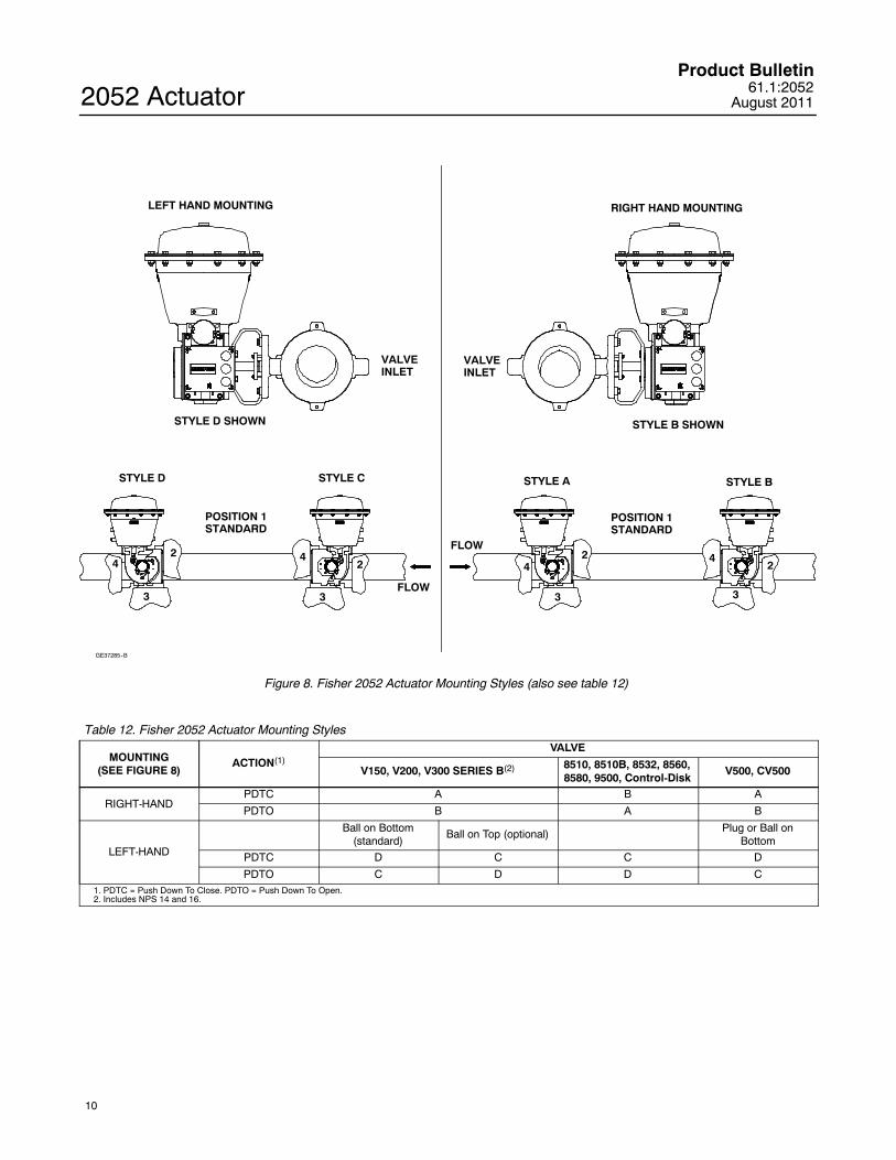
Figure 8. Fisher 2052 Actuator Mounting Styles (also see table 12)
Table 12. Fisher 2052 Actuator Mounting Styles
MOUNTING(SEE FIGURE 8)
ACTION(1)VALVE
V150, V200, V300 SERIES B(2) 8510, 8510B, 8532, 8560,8580, 9500, Control-Disk
V500, CV500
RIGHT-HANDPDTC A B A
PDTO B A B
LEFT-HAND
Ball on Bottom(standard)
Ball on Top (optional) Plug or Ball onBottom
PDTC D C C D
PDTO C D D C1. PDTC = Push Down To Close. PDTO = Push Down To Open.2. Includes NPS 14 and 16.

2052 ActuatorProduct Bulletin61.1:2052August 2011
11

2052 ActuatorProduct Bulletin
61.1:2052August 2011
12
Emerson Process ManagementMarshalltown, Iowa 50158 USASorocaba, 18087 BrazilChatham, Kent ME4 4QZ UKDubai, United Arab EmiratesSingapore 128461 Singapore
EFisher Controls International LLC 2008, 2011; All Rights Reserved
www.Fisher.com
The contents of this publication are presented for informational purposes only, and while every effort has been made to ensure their accuracy, theyare not to be construed as warranties or guarantees, express or implied, regarding the products or services described herein or their use orapplicability. All sales are governed by our terms and conditions, which are available upon request. We reserve the right to modify or improve thedesigns or specifications of such products at any time without notice.
Fisher, Control--Disk, GO, and TopWorx are marks owned by one of the companies in the Emerson Process Management business division ofEmerson Electric Co. Emerson Process Management, Emerson, and the Emerson logo are trademarks and service marks of Emerson Electric Co.All other marks are the property of their respective owners.
Neither Emerson, Emerson Process Management, nor any of their affiliated entities assumes responsibility for the selection, use ormaintenance of any product. Responsibility for proper selection, use, and maintenance of any product remains solely with thepurchaser and end user.