first published 2002 building, design version 02 and
TRANSCRIPT
administered by
BDM13First published 2002 Version 02
Building, Design and ManagementFire safety engineeringA guide for insurers
2 3
IMPORTANT NOTICE
This document has been developed through the RISCAuthority and published by the Fire Protection Association (FPA). RISCAuthority membership comprises a group of UK insurers that actively support a number of expert working groups developing and promulgating best practice for the protection of people, property, business and the environment from loss due to fire and other risks. The technical expertise for this document has been provided by the Technical Directorate of the FPA, external consultants, and experts from the insurance industry who together form the various RISCAuthority Working Groups. Although produced with insurer input it does not (and is not intended to) represent a pan-insurer perspective. Individual insurance companies will have their own requirements which may be different from or not reflected in the content of this document.
The FPA has made extensive efforts to check the accuracy of the information and advice contained in this document and it is believed to be accurate at the time of printing. However, the FPA makes no guarantee, representation or warranty (express or implied) as to the accuracy or completeness of any information or advice contained in this document. All advice and recommendations are presented in good faith on the basis of information, knowledge and technology as at the date of publication of this document.
Without prejudice to the generality of the foregoing, the FPA makes no guarantee, representation or warranty (express or implied) that this document considers all systems, equipment and procedures or state-of-the-art technologies current at the date of this document.
Use of, or reliance upon, this document, or any part of its content, is voluntary and is at the user’s own risk. Anyone considering using or implementing any recommendation or advice within this document should rely on his or her own personal judgement or, as appropriate, seek the advice of a competent professional and rely on that professional’s advice. Nothing in this document replaces or excludes (nor is intended to replace or exclude), entirely or in part, mandatory and/or legal requirements howsoever arising (including without prejudice to the generality of the foregoing any such requirements for maintaining health and safety in the workplace).
Except to the extent that it is unlawful to exclude any liability, the FPA accepts no liability whatsoever for any direct, indirect or consequential loss or damage arising in any way from the publication of this document or any part of it, or any use of, or reliance placed on, the content of this document or any part of it.
CONTENTS
Overview 3
Summary 3
1. Introduction 3
2. Background 3
3. FSE defined 6
4. Key calculations 9
5. Insurer participation 14
6. Conclusions 15
7. References 15
2 3
OVERVIEW
This revised document provides a simple guide on fire safety
engineering for the commercial property insurer. It updates the
2002 version produced through ABI’s Medium Term Research
Strategy, and fulfils the request from RISCAuthority members for
a simple guide on fire safety engineering.
SUMMARY
Fire safety engineering (FSE) is a relatively new discipline applied
to fire performance aspects of building design. It is of particular
relevance to insurers and others involved in the specification of fire
protection, as it is intended to offer an alternative to compliance
with the traditional prescriptive Building Regulations.
Existing guidance and technical papers on fire safety engineering
do not address the needs of insurers, nor do they explain the
basis of requirements insurers may have.
This report gives guidance on fire safety engineering for insurers.
In particular, it gives an overview of FSE (background, application,
basis of calculation, typical design solutions), defines specific
insurer requirements, actions, decisions, and implications
(eg impact on retention and rating) and highlights risks and
benefits to insurers.
1. INTRODUCTION
Fire safety engineering is a relatively new discipline applied to
fire performance aspects of building design. It is of particular
relevance to insurers and others involved in the specification of fire
protection, as it is intended to offer an alternative to compliance
with the traditional prescriptive Building Regulations.
Generally, FSE solutions are intended to meet the requirements
under Building Regulations for life safety. Consequently, they are
unlikely to meet insurer and client requirements for the protection
of property (ie buildings and contents) or for the protection of
businesses against loss or damage by fire to the means of
production or earning of revenue.
Prescriptive requirements of the Building Regulations are well
understood and tested. Innovative solutions to meet Building
Regulations using FSE are likely to be met with circumspection by
insurers and other specifiers unless they can be demonstrated to
address fundamental requirements for both property protection
and business interruption.
Existing guidance and technical papers on FSE do not
acknowledge the role of insurers, nor do they explain the basis of
requirements they may make. This guide:
• gives an overview of FSE (background, application, basis of
calculation, typical design solutions);
• defines specific insurer requirements, actions, decisions, and
implications (eg impact on retention and rating); and
• highlights risks and benefits to insurers.
2. BACKGROUND
2.1 Regulations and recommendations
Building design involving FSE has gained momentum
following the release of a new edition of Approved
Document B (ADB) in 1992 (ref. 1). The ADB contains
practical guidance on meeting the Building Regulations
relating to fire safety (ref. 2) and introduced the statement
that ‘fire safety engineering can provide an alternative
approach to fire safety’.
FSE is approached in a similar manner to other engineering
disciplines and is dependent on fire science and
calculation methods. In 1997, the first British Standard
Draft for Development on fire safety engineering was
published, DD 240 (ref. 3), which was later converted into
a full British Standard, BS 7974: Application of fire safety
engineering principles to the design of buildings. Code
of practice, and published in 2001. This code provides
the framework and describes the philosophy of FSE and
also outlines the principles involved in the application of
the philosophy to the fire safety engineering of particular
buildings. It is supported by a series of seven Published
Documents, PDs, that contain guidance and information
on how to undertake detailed analysis of specific aspects.
These PDs are a summary of the state of the art and it
is intended they be updated as new theories, calculation
methods and/or data become available.
Initially, required qualifications for those carrying out
FSE lacked clarity. The practice of FSE requires detailed
knowledge of fire science (hazards, events, modelling
techniques) and a scientific approach. The Institution of
Fire Engineers (IFE) Registrants Group has established an
appropriate education/experience package necessary for
qualification as a chartered fire engineer. With a suitable
period allowed for uptake, all future fire safety engineers
should be registered as chartered.
2.2 Application
Typical buildings where FSE is applied are shopping
complexes, commercial buildings containing atria,
entertainment venues, airports and stations. The common
characteristics for these buildings tend to be:
• prestigious and of unique design;
• large open spaces; and
• occupied by large numbers of people.
Large buildings with few people, eg warehousing and
industrial sites, are less commonly subject to FSE design.
While, in theory, FSE should be used for the design of a
whole building, the practicalities of this usually mean that it
is performed on limited design details, typically:
• travel distance (or other exit requirements in relation to
the number of people);
• fire resistance of elements of the construction; and
• size of uncompartmented space.
Therefore, most parts of the completed building will be
in accordance with ADB (ref. 4) and standards. Only the
detail (eg travel distance) and its implications on the rest of
the building will be considered.
Typical aims of FSE projects are to allow innovative building
design features and cost-effective fire safety solutions. This
is possible because the FSE approach permits fire safety
solutions that a) depart or b) have no standard prescriptive
recommendations given in ADB and supporting
standards (eg BS 5588: Fire precautions in the design,
construction and use of buildings. Code of practice for
4 5
residential buildings (ref. 5)). This permits novel materials,
new design concepts or a new fire protection strategy
without compromising the project by compliance with
restrictive conventional fire safety requirements.
The basis for departure from prescriptive recommendations
is by demonstrating that with a ‘reasonable worst case fire
scenario’ the FSE design presents:
• minimal risk to life, ie a risk less than or equal to that
under current ADB recommendations or a risk less
than current statistics;
• acceptable risk to environment; and
• acceptable risk to property (building, contents and
business continuity).
The environmental and property risks are rarely considered
in a FSE design, due to a lack of regulatory requirements.
However, conscientious risk-aware clients who consider
these risks at the earliest stages of design see benefits
in later years (fewer or smaller fire incidents, improved
business resilience, and lower or less onerous insurance
costs and terms).
2.3 Insurance risk
Insurer objectives for FSE design are addressed in the
FPA Design guide (see Box 1) (ref. 6). Additional FSE
design guides for specific types of premises detail series of
recommendations. Property objectives are also proposed
in BS 7974: 2001 (ref. 7) (see Box 2).
When assessing the risk to property/business by fire (or
other perils) of a design solution, an insurer may consider
all or any of the following:
• normal loss expectancy (NLE);
• estimated maximum loss (EML); and
• maximum foreseeable loss (MFL).
Precise definitions of these vary but are, in essence,
as follows:
NLE will assume normal circumstances, all available means
of protection, both public and private, are functioning
as intended. Loss is expected to be due to a single fire,
not multiple seats, nor a catastrophic event (ie possible
but unlikely).
EML will assume poor circumstances, with some of the
available private means of protection not functioning
(eg fire doors and sprinklers). Loss is expected to be due
to a single fire, not multiple seats, nor a catastrophic event.
This case allows the ‘what if’ scenarios to be considered
and evaluated, eg sprinklers operating or not.
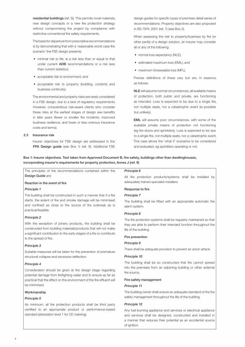
Box 1: Insurer objectives. Text taken from Approved Document B, fire safety, buildings other than dwellinghouses,
incorporating insurer’s requirements for property protection, Annex J (ref. 8)
The principles of the recommendations contained within the
Design Guide are:
Reaction in the event of fire
Principle 1
The building shall be constructed in such a manner that if a fire
starts, the extent of fire and smoke damage will be minimised
and confined as close to the source of fire outbreak as is
practical/feasible.
Principle 2
With the exception of joinery products, the building shall be
constructed from building materials/products that will not make
a significant contribution to the early stages of a fire or contribute
to the spread of fire.
Principle 3
Suitable measures will be taken for the prevention of premature
structural collapse and excessive deflection.
Principle 4
Consideration should be given at the design stage regarding
potential damage from firefighting water and to ensure as far as
practical that the effect on the environment of the fire effluent will
be minimised.
Workmanship
Principle 5
As minimum, all fire protection products shall be third party
certified to an appropriate product or performance-based
standard (attestation level 1 for CE marking)
Principle 6
All fire protection products/systems shall be installed by
adequately trained specialist installers.
Response to fire
Principle 7
The building shall be fitted with an appropriate automatic fire
alarm system.
Principle 8
The fire protection systems shall be regularly maintained so that
they are able to perform their intended function throughout the
life of the building.
Fire prevention
Principle 9
There shall be adequate provision to prevent an arson attack.
Principle 10
The building shall be so constructed that fire cannot spread
into the premises from an adjoining building or other external
fire source.
Fire safety management
Principle 11
The building owner shall ensure an adequate standard of the fire
safety management throughout the life of the building.
Principle 12
Any fuel-burning appliance and services or electrical appliance
and services shall be designed, constructed and installed in
a manner that reduces their potential as an accidental source
of ignition.
4 5
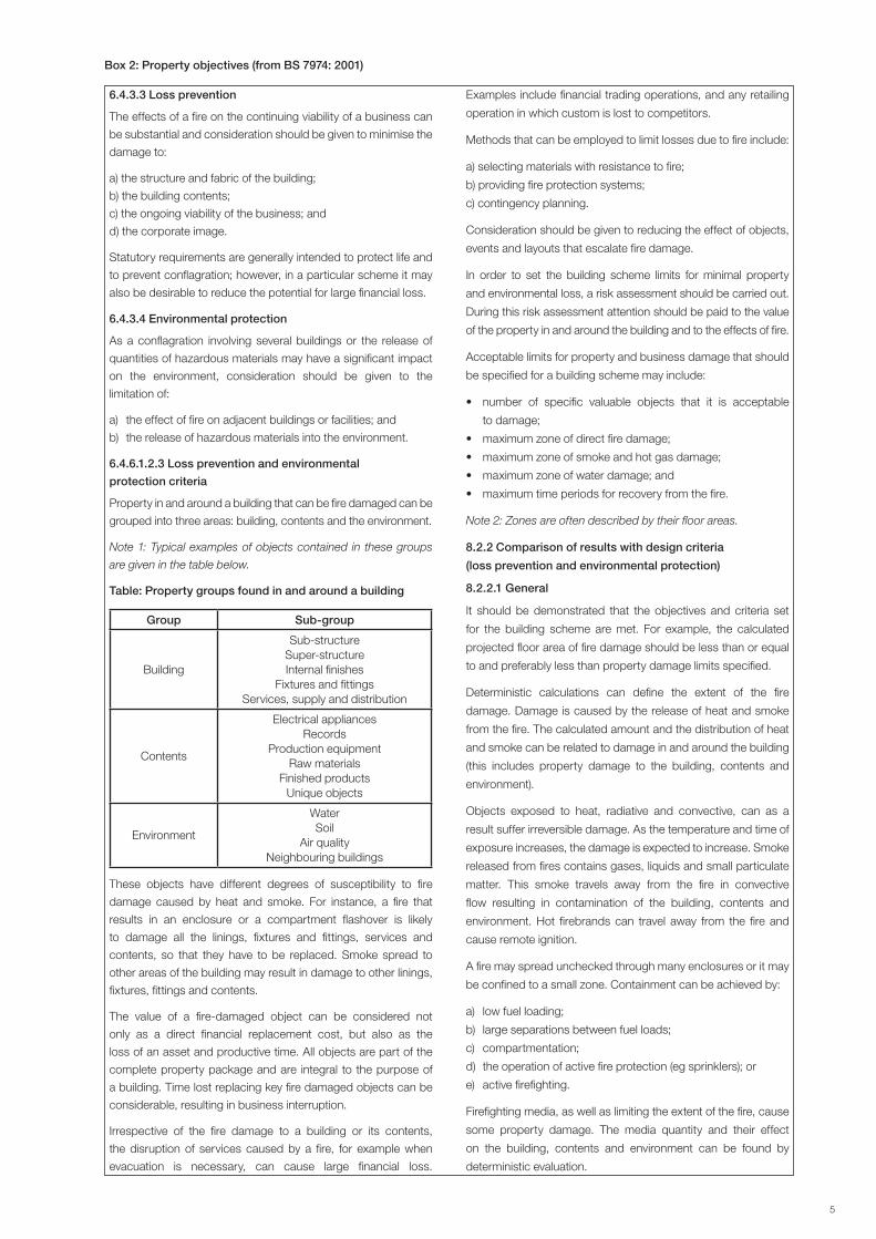
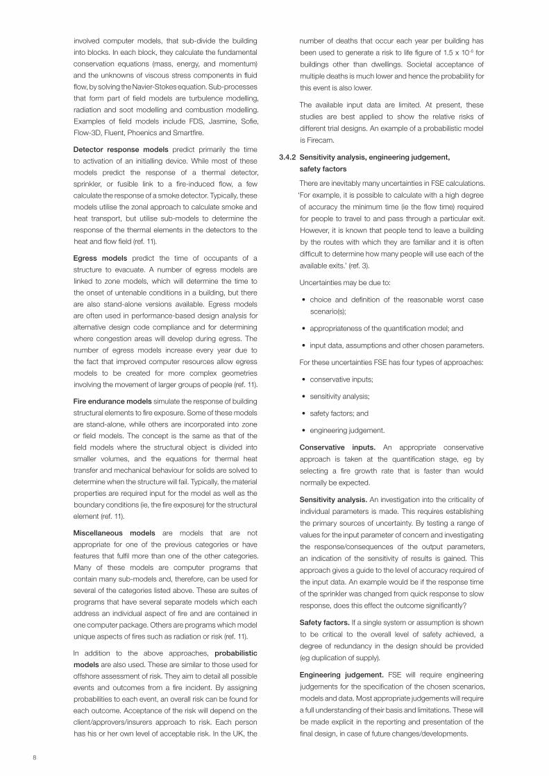
Box 2: Property objectives (from BS 7974: 2001)
6.4.3.3 Loss prevention
The effects of a fire on the continuing viability of a business can
be substantial and consideration should be given to minimise the
damage to:
a) the structure and fabric of the building;
b) the building contents;
c) the ongoing viability of the business; and
d) the corporate image.
Statutory requirements are generally intended to protect life and
to prevent conflagration; however, in a particular scheme it may
also be desirable to reduce the potential for large financial loss.
6.4.3.4 Environmental protection
As a conflagration involving several buildings or the release of
quantities of hazardous materials may have a significant impact
on the environment, consideration should be given to the
limitation of:
a) the effect of fire on adjacent buildings or facilities; and
b) the release of hazardous materials into the environment.
6.4.6.1.2.3 Loss prevention and environmental
protection criteria
Property in and around a building that can be fire damaged can be
grouped into three areas: building, contents and the environment.
Note 1: Typical examples of objects contained in these groups
are given in the table below.
Table: Property groups found in and around a building
Group Sub-group
Building
Sub-structureSuper-structureInternal finishes
Fixtures and fittingsServices, supply and distribution
Contents
Electrical appliancesRecords
Production equipmentRaw materials
Finished productsUnique objects
Environment
WaterSoil
Air qualityNeighbouring buildings
These objects have different degrees of susceptibility to fire
damage caused by heat and smoke. For instance, a fire that
results in an enclosure or a compartment flashover is likely
to damage all the linings, fixtures and fittings, services and
contents, so that they have to be replaced. Smoke spread to
other areas of the building may result in damage to other linings,
fixtures, fittings and contents.
The value of a fire-damaged object can be considered not
only as a direct financial replacement cost, but also as the
loss of an asset and productive time. All objects are part of the
complete property package and are integral to the purpose of
a building. Time lost replacing key fire damaged objects can be
considerable, resulting in business interruption.
Irrespective of the fire damage to a building or its contents,
the disruption of services caused by a fire, for example when
evacuation is necessary, can cause large financial loss.
Examples include financial trading operations, and any retailing
operation in which custom is lost to competitors.
Methods that can be employed to limit losses due to fire include:
a) selecting materials with resistance to fire;
b) providing fire protection systems;
c) contingency planning.
Consideration should be given to reducing the effect of objects,
events and layouts that escalate fire damage.
In order to set the building scheme limits for minimal property
and environmental loss, a risk assessment should be carried out.
During this risk assessment attention should be paid to the value
of the property in and around the building and to the effects of fire.
Acceptable limits for property and business damage that should
be specified for a building scheme may include:
• number of specific valuable objects that it is acceptable
to damage;
• maximum zone of direct fire damage;
• maximum zone of smoke and hot gas damage;
• maximum zone of water damage; and
• maximum time periods for recovery from the fire.
Note 2: Zones are often described by their floor areas.
8.2.2 Comparison of results with design criteria
(loss prevention and environmental protection)
8.2.2.1 General
It should be demonstrated that the objectives and criteria set
for the building scheme are met. For example, the calculated
projected floor area of fire damage should be less than or equal
to and preferably less than property damage limits specified.
Deterministic calculations can define the extent of the fire
damage. Damage is caused by the release of heat and smoke
from the fire. The calculated amount and the distribution of heat
and smoke can be related to damage in and around the building
(this includes property damage to the building, contents and
environment).
Objects exposed to heat, radiative and convective, can as a
result suffer irreversible damage. As the temperature and time of
exposure increases, the damage is expected to increase. Smoke
released from fires contains gases, liquids and small particulate
matter. This smoke travels away from the fire in convective
flow resulting in contamination of the building, contents and
environment. Hot firebrands can travel away from the fire and
cause remote ignition.
A fire may spread unchecked through many enclosures or it may
be confined to a small zone. Containment can be achieved by:
a) low fuel loading;
b) large separations between fuel loads;
c) compartmentation;
d) the operation of active fire protection (eg sprinklers); or
e) active firefighting.
Firefighting media, as well as limiting the extent of the fire, cause
some property damage. The media quantity and their effect
on the building, contents and environment can be found by
deterministic evaluation.
6 7
MFL will assume most adverse circumstances, with all
available means of protection, both public and private, not
functioning. Loss is expected to be due to a ‘worse case’
fire, not a catastrophic event. This case assumes the end
of the fire event will be due to fire burn out.
The insurance and FSE evaluation methods are similar
in that they both use fire scenarios. However, the FSE
approach tends to assume that all circumstances
are normal (ie NLE, except where there are life safety
implications with a particular circumstance), while the
insurance approach additionally investigates other worse
scenarios (eg protection system failures).
3. FSE DEFINED
3.1 Design, construction and management of buildings
The anticipated design life of most buildings is about 50
years. The type of construction and occupancy, of course,
will have a great influence. For example, what we now
consider as heritage buildings have stood in one form or
another for hundreds of years and structures for events,
such as the Millennium Dome in London, have a design
life of just two years. This design life and the vision for a
building are the fundamental starting points for clients in
the design process.
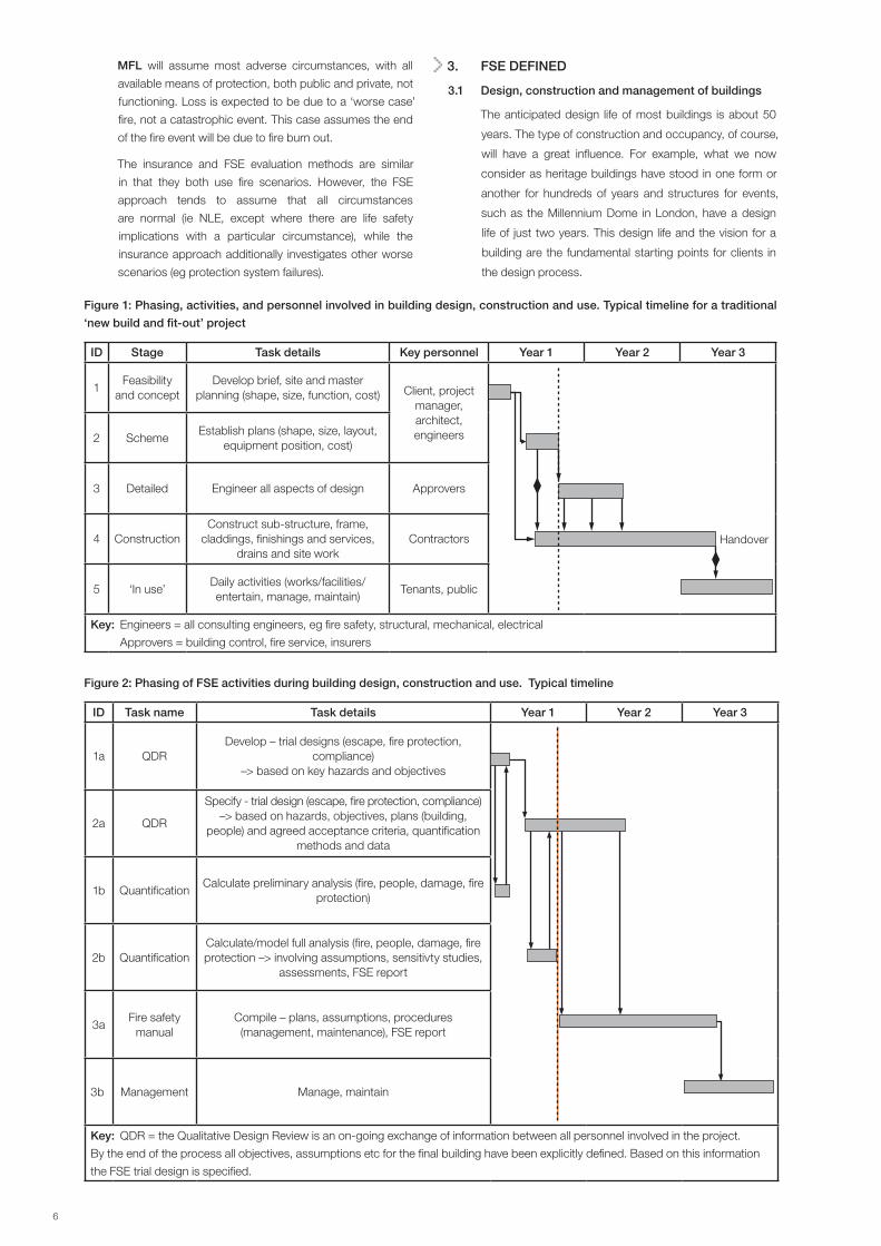
Figure 1: Phasing, activities, and personnel involved in building design, construction and use. Typical timeline for a traditional
‘new build and fit-out’ project
ID Stage Task details Key personnel Year 1 Year 2 Year 3
1Feasibility
and conceptDevelop brief, site and master
planning (shape, size, function, cost) Client, project manager, architect, engineers
Handover
2 SchemeEstablish plans (shape, size, layout,
equipment position, cost)
3 Detailed Engineer all aspects of design Approvers
4 ConstructionConstruct sub-structure, frame,
claddings, finishings and services, drains and site work
Contractors
5 ‘In use’Daily activities (works/facilities/entertain, manage, maintain)
Tenants, public
Key: Engineers = all consulting engineers, eg fire safety, structural, mechanical, electrical
Approvers = building control, fire service, insurers
Figure 2: Phasing of FSE activities during building design, construction and use. Typical timeline
ID Task name Task details Year 1 Year 2 Year 3
1a QDRDevelop – trial designs (escape, fire protection,
compliance)–> based on key hazards and objectives
2a QDR
Specify - trial design (escape, fire protection, compliance)–> based on hazards, objectives, plans (building,
people) and agreed acceptance criteria, quantification methods and data
1b QuantificationCalculate preliminary analysis (fire, people, damage, fire
protection)
2b QuantificationCalculate/model full analysis (fire, people, damage, fire protection –> involving assumptions, sensitivty studies,
assessments, FSE report
3aFire safety
manualCompile – plans, assumptions, procedures (management, maintenance), FSE report
3b Management Manage, maintain
Key: QDR = the Qualitative Design Review is an on-going exchange of information between all personnel involved in the project.
By the end of the process all objectives, assumptions etc for the final building have been explicitly defined. Based on this information
the FSE trial design is specified.

6 7
There are many types of design and build contracts,
each with tasks and responsibilities arranged differently.
However, they all proceed through the same stages (see
Figure 1). Very early in the design process, Stage 1, details
such as water supplies and points of access/exit are
decided, along with associated budgets and costs. Plans,
performance criteria and costs may be fairly fixed before the
approving authorities and insurers are consulted (planning
application in Stage 2). Hence, it is important for clients to
be aware and have access to insurer requirements when
they embark on a design/build project.
Detailed design and construction phase (Stages 3 and 4)
will involve intensive effort to ensure conformity to design
requirements/specifications. Linked with this are the health
and safety at work requirements (ref. 9) – in particular,
the health and safety manual that is developed for the
construction phase (ref. 10).
Only after handover will the client’s vision for a building and
design life be realised and tested. The fire safety design will
take into account the type and standard of management
expected over the working life of the building.
3.2 FSE as a component of building design
construction/management
FSE has three key components:
• QDR – qualitative design review;
• quantification – quantitative analysis; and
• fire safety manual – reporting and management.
Figure 2 shows how the FSE design activities link into the
different project phases.
3.3 Qualitative design review (QDR)
The objective of the QDR is to assess the project and define
the problem in qualitative terms (eg reasonable worst case
scenario) suitable for detailed analysis and quantification.
An important function of the QDR is to establish one or more
fire protection schemes (trial designs) that are considered
likely to satisfy the fire safety criteria. QDR requires the
explicit definition of project details and assumptions for
the final building by personnel involved. Generally, this is
established through ongoing exchanges of information
between key personnel, and recorded in the FSE report.
On major projects, this will involve members of the design
team, fire safety engineers, appropriate approval bodies,
insurers and operational management.
Tasks carried out in the QDR are:
• review the architectural design;
• determine building, environment and occupant
characteristics;
• establish the fire safety/protection objectives;
• establish an evacuation strategy;
• identify acceptance criteria;
• identify fire hazards and possible consequences;
• establish trial fire safety/protection designs;
• specify reasonable worst case fire scenario(s) for
analysis;
• indicate appropriate methods of analysis; and
• report the results of the QDR.
3.4 Quantification
The analysis will evaluate the impact of a fire on people and
property at different times in the development of a fire.
For the ‘reasonable worst case fire scenario’ the
characteristic doses of heat and other potential hazards
(eg toxic and corrosive smoke, loss of visibility) are
determined for:
• fire growth and development;
• spread of combustion products;
• spread of fire from the enclosure of origin; and
• fire control (by active systems operation or fire service
intervention).
The impact of the described fire doses are used to evaluate
times to:
• fire detection;
• sprinkler operation;
• fire ventilation operation;
• structural failure; and
• fire service intervention.
Ultimately, the analysis determines if safe evacuation of
occupants is possible and the extent of areas that will
be damaged by the fire incident (location and degree of
damage).
3.4.1 Quantification methods
The quantitative analysis can take different forms according
to the problem. Quantification methods (calculations
and fire models) are based on physical, chemical,
thermodynamic and human behavioural relationships,
derived from scientific theories and empirical calculations.
Some of the calculations are outlined in BS 7974: 2001.
Fire models that are frequently used are of two types: zone
and field.
Zone models take a few minutes to run on a personal
computer. They are set up to give dose and impact
calculation (eg ceiling temperatures and time to sprinkler
operations). Zone models calculate average temperature in
a fire enclosure and the average velocity of air entering and
leaving the enclosure. They divide a fire enclosure into two
zones separated by a horizontal plane. The influence of the
fire plume as a heat/mass (including entrained air) pump
into the upper zone is calculated. Some assumptions are
made (eg simple geometry, ideal gas, turbulence, heat
and mass capacity of contents). Examples of zone models
include Hazard1, Cfast and Fastlite.
Field models precisely define the dose and use post-
processing to calculate the impact on a target. A single
trial design can take several days to calculate. As
processor speed increases and the model/user interface
improves, the use of these models for design is expected
to increase. Field or CFD models predict the two- and
three-dimensional distribution of velocity and temperature
in a building from a known fire source. They are complex,
8 9
involved computer models, that sub-divide the building
into blocks. In each block, they calculate the fundamental
conservation equations (mass, energy, and momentum)
and the unknowns of viscous stress components in fluid
flow, by solving the Navier-Stokes equation. Sub-processes
that form part of field models are turbulence modelling,
radiation and soot modelling and combustion modelling.
Examples of field models include FDS, Jasmine, Sofie,
Flow-3D, Fluent, Phoenics and Smartfire.
Detector response models predict primarily the time
to activation of an initialling device. While most of these
models predict the response of a thermal detector,
sprinkler, or fusible link to a fire-induced flow, a few
calculate the response of a smoke detector. Typically, these
models utilise the zonal approach to calculate smoke and
heat transport, but utilise sub-models to determine the
response of the thermal elements in the detectors to the
heat and flow field (ref. 11).
Egress models predict the time of occupants of a
structure to evacuate. A number of egress models are
linked to zone models, which will determine the time to
the onset of untenable conditions in a building, but there
are also stand-alone versions available. Egress models
are often used in performance-based design analysis for
alternative design code compliance and for determining
where congestion areas will develop during egress. The
number of egress models increase every year due to
the fact that improved computer resources allow egress
models to be created for more complex geometries
involving the movement of larger groups of people (ref. 11).
Fire endurance models simulate the response of building
structural elements to fire exposure. Some of these models
are stand-alone, while others are incorporated into zone
or field models. The concept is the same as that of the
field models where the structural object is divided into
smaller volumes, and the equations for thermal heat
transfer and mechanical behaviour for solids are solved to
determine when the structure will fail. Typically, the material
properties are required input for the model as well as the
boundary conditions (ie, the fire exposure) for the structural
element (ref. 11).
Miscellaneous models are models that are not
appropriate for one of the previous categories or have
features that fulfil more than one of the other categories.
Many of these models are computer programs that
contain many sub-models and, therefore, can be used for
several of the categories listed above. These are suites of
programs that have several separate models which each
address an individual aspect of fire and are contained in
one computer package. Others are programs which model
unique aspects of fires such as radiation or risk (ref. 11).
In addition to the above approaches, probabilistic
models are also used. These are similar to those used for
offshore assessment of risk. They aim to detail all possible
events and outcomes from a fire incident. By assigning
probabilities to each event, an overall risk can be found for
each outcome. Acceptance of the risk will depend on the
client/approvers/insurers approach to risk. Each person
has his or her own level of acceptable risk. In the UK, the
number of deaths that occur each year per building has
been used to generate a risk to life figure of 1.5 x 10⁻⁶ for
buildings other than dwellings. Societal acceptance of
multiple deaths is much lower and hence the probability for
this event is also lower.
The available input data are limited. At present, these
studies are best applied to show the relative risks of
different trial designs. An example of a probabilistic model
is Firecam.
3.4.2 Sensitivity analysis, engineering judgement,
safety factors
There are inevitably many uncertainties in FSE calculations.
‘For example, it is possible to calculate with a high degree
of accuracy the minimum time (ie the flow time) required
for people to travel to and pass through a particular exit.
However, it is known that people tend to leave a building
by the routes with which they are familiar and it is often
difficult to determine how many people will use each of the
available exits.’ (ref. 3).
Uncertainties may be due to:
• choice and definition of the reasonable worst case
scenario(s);
• appropriateness of the quantification model; and
• input data, assumptions and other chosen parameters.
For these uncertainties FSE has four types of approaches:
• conservative inputs;
• sensitivity analysis;
• safety factors; and
• engineering judgement.
Conservative inputs. An appropriate conservative
approach is taken at the quantification stage, eg by
selecting a fire growth rate that is faster than would
normally be expected.
Sensitivity analysis. An investigation into the criticality of
individual parameters is made. This requires establishing
the primary sources of uncertainty. By testing a range of
values for the input parameter of concern and investigating
the response/consequences of the output parameters,
an indication of the sensitivity of results is gained. This
approach gives a guide to the level of accuracy required of
the input data. An example would be if the response time
of the sprinkler was changed from quick response to slow
response, does this effect the outcome significantly?
Safety factors. If a single system or assumption is shown
to be critical to the overall level of safety achieved, a
degree of redundancy in the design should be provided
(eg duplication of supply).
Engineering judgement. FSE will require engineering
judgements for the specification of the chosen scenarios,
models and data. Most appropriate judgements will require
a full understanding of their basis and limitations. These will
be made explicit in the reporting and presentation of the
final design, in case of future changes/developments.
8 9
3.5 Fire safety manual
Essential to the continuation of the building and risk as
intended will be compliance to specifications made in the
fire safety manual. The fire safety manual should have been
created by the project manager of the QDR and updated
throughout detailed design and construction phases. It
should be kept on the premises concerned, for the benefit
of those managing the premises.
This fire safety manual should reflect the general
management and operational procedures of the
organisation concerned. It should be a definitive document
that includes sufficient information for maintenance staff,
whether in-house, contracted, or specialist equipment
suppliers, concerning the safe undertaking of any building
or engineering work. Because of the integrated nature of
building and engineering work, the technical specifications
of all aspects of the building should be included in the fire
safety manual.
The manual should cover the following:
1. fire safety policy statement;
2. fire safety specification for the building;
3. safety management structure;
4. continuing control and audit procedures;
5. actions to be taken in a fire emergency;
6. fire drills;
7. housekeeping;
8. planned maintenance procedures;
9. staff training;
10. security;
11. contingency plans for damage control and salvage;
and
12. record keeping.
More details of the fire safety manual are given in BS 9999:
2008: Code of practice for fire safety in the design,
management and use of buildings Annex H (ref. 12).
Attached to the fire safety manual should be the FSE report.
This report will form the basis of much of the content of the
fire safety manual.
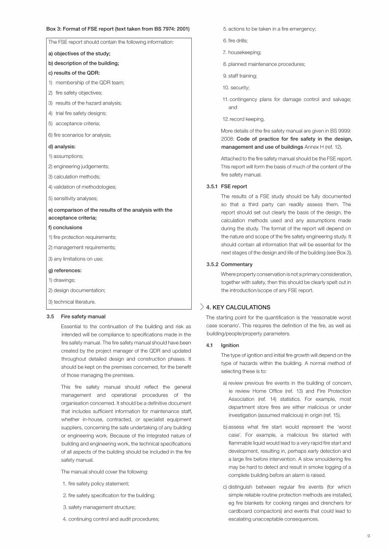
3.5.1 FSE report
The results of a FSE study should be fully documented
so that a third party can readily assess them. The
report should set out clearly the basis of the design, the
calculation methods used and any assumptions made
during the study. The format of the report will depend on
the nature and scope of the fire safety engineering study. It
should contain all information that will be essential for the
next stages of the design and life of the building (see Box 3).
3.5.2 Commentary
Where property conservation is not a primary consideration,
together with safety, then this should be clearly spelt out in
the introduction/scope of any FSE report.
4. KEY CALCULATIONS
The starting point for the quantification is the ‘reasonable worst
case scenario’. This requires the definition of the fire, as well as
building/people/property parameters.
4.1 Ignition
The type of ignition and initial fire growth will depend on the
type of hazards within the building. A normal method of
selecting these is to:
a) review previous fire events in the building of concern,
ie review Home Office (ref. 13) and Fire Protection
Association (ref. 14) statistics. For example, most
department store fires are either malicious or under
investigation (assumed malicious) in origin (ref. 15).
b) assess what fire start would represent the ‘worst
case’. For example, a malicious fire started with
flammable liquid would lead to a very rapid fire start and
development, resulting in, perhaps early detection and
a large fire before intervention. A slow smouldering fire
may be hard to detect and result in smoke logging of a
complete building before an alarm is raised.
c) distinguish between regular fire events (for which
simple reliable routine protection methods are installed,
eg fire blankets for cooking ranges and drenchers for
cardboard compactors) and events that could lead to
escalating unacceptable consequences.
Box 3: Format of FSE report (text taken from BS 7974: 2001)
The FSE report should contain the following information:
a) objectives of the study;
b) description of the building;
c) results of the QDR:
1) membership of the QDR team;
2) fire safety objectives;
3) results of the hazard analysis;
4) trial fire safety designs;
5) acceptance criteria;
6) fire scenarios for analysis;
d) analysis:
1) assumptions;
2) engineering judgements;
3) calculation methods;
4) validation of methodologies;
5) sensitivity analyses;
e) comparison of the results of the analysis with the
acceptance criteria;
f) conclusions
1) fire protection requirements;
2) management requirements;
3) any limitations on use;
g) references:
1) drawings;
2) design documentation;
3) technical literature.
10 11
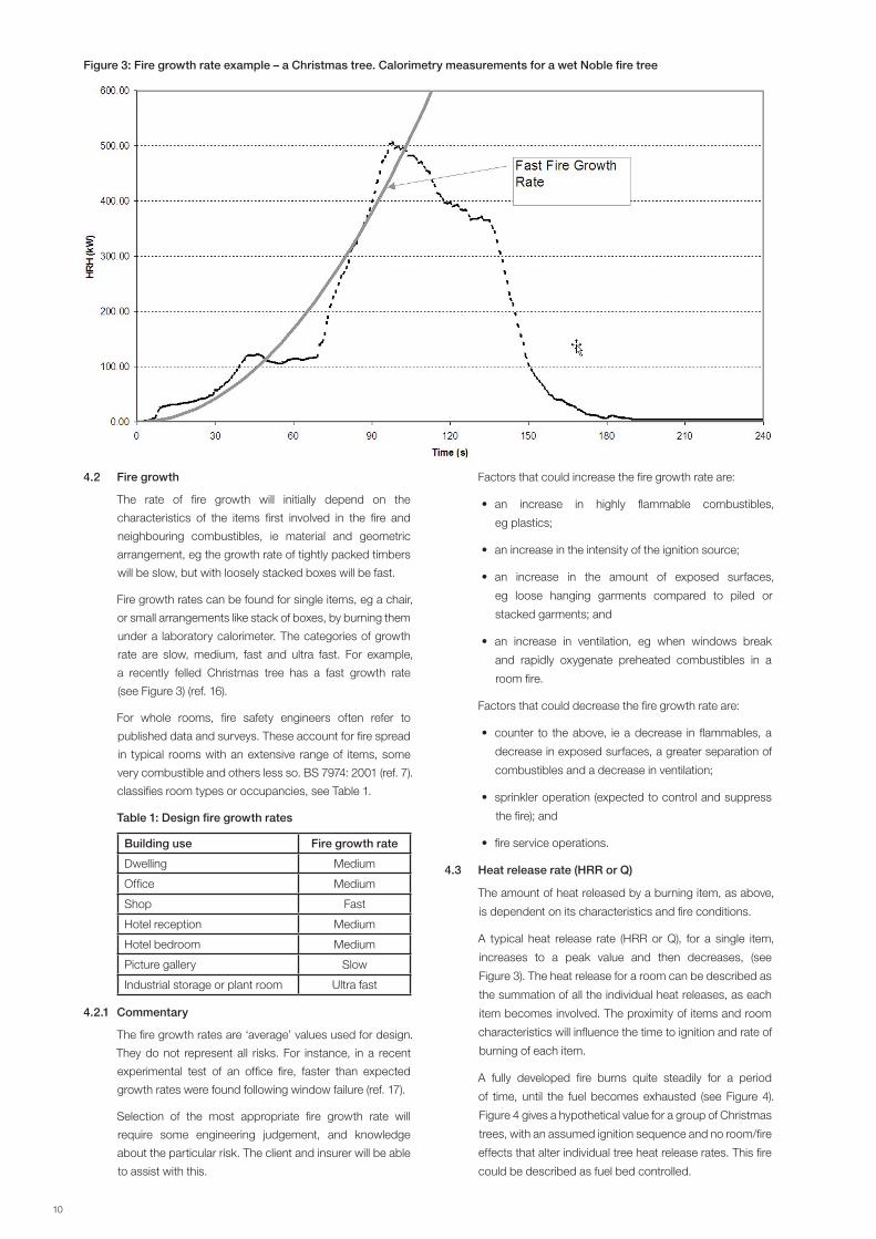
4.2 Fire growth
The rate of fire growth will initially depend on the
characteristics of the items first involved in the fire and
neighbouring combustibles, ie material and geometric
arrangement, eg the growth rate of tightly packed timbers
will be slow, but with loosely stacked boxes will be fast.
Fire growth rates can be found for single items, eg a chair,
or small arrangements like stack of boxes, by burning them
under a laboratory calorimeter. The categories of growth
rate are slow, medium, fast and ultra fast. For example,
a recently felled Christmas tree has a fast growth rate
(see Figure 3) (ref. 16).
For whole rooms, fire safety engineers often refer to
published data and surveys. These account for fire spread
in typical rooms with an extensive range of items, some
very combustible and others less so. BS 7974: 2001 (ref. 7).
classifies room types or occupancies, see Table 1.
Table 1: Design fire growth rates
Building use Fire growth rate
Dwelling Medium
Office Medium
Shop Fast
Hotel reception Medium
Hotel bedroom Medium
Picture gallery Slow
Industrial storage or plant room Ultra fast
4.2.1 Commentary
The fire growth rates are ‘average’ values used for design.
They do not represent all risks. For instance, in a recent
experimental test of an office fire, faster than expected
growth rates were found following window failure (ref. 17).
Selection of the most appropriate fire growth rate will
require some engineering judgement, and knowledge
about the particular risk. The client and insurer will be able
to assist with this.
Factors that could increase the fire growth rate are:
• an increase in highly flammable combustibles,
eg plastics;
• an increase in the intensity of the ignition source;
• an increase in the amount of exposed surfaces,
eg loose hanging garments compared to piled or
stacked garments; and
• an increase in ventilation, eg when windows break
and rapidly oxygenate preheated combustibles in a
room fire.
Factors that could decrease the fire growth rate are:
• counter to the above, ie a decrease in flammables, a
decrease in exposed surfaces, a greater separation of
combustibles and a decrease in ventilation;
• sprinkler operation (expected to control and suppress
the fire); and
• fire service operations.
4.3 Heat release rate (HRR or Q)
The amount of heat released by a burning item, as above,
is dependent on its characteristics and fire conditions.
A typical heat release rate (HRR or Q), for a single item,
increases to a peak value and then decreases, (see
Figure 3). The heat release for a room can be described as
the summation of all the individual heat releases, as each
item becomes involved. The proximity of items and room
characteristics will influence the time to ignition and rate of
burning of each item.
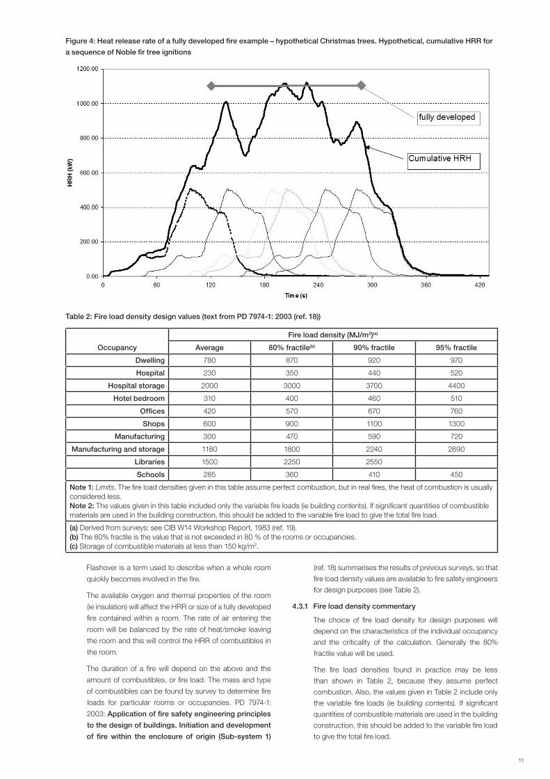
A fully developed fire burns quite steadily for a period
of time, until the fuel becomes exhausted (see Figure 4).
Figure 4 gives a hypothetical value for a group of Christmas
trees, with an assumed ignition sequence and no room/fire
effects that alter individual tree heat release rates. This fire
could be described as fuel bed controlled.
Figure 3: Fire growth rate example – a Christmas tree. Calorimetry measurements for a wet Noble fire tree
10 11
Flashover is a term used to describe when a whole room
quickly becomes involved in the fire.
The available oxygen and thermal properties of the room
(ie insulation) will affect the HRR or size of a fully developed
fire contained within a room. The rate of air entering the
room will be balanced by the rate of heat/smoke leaving
the room and this will control the HRR of combustibles in
the room.
The duration of a fire will depend on the above and the
amount of combustibles, or fire load. The mass and type
of combustibles can be found by survey to determine fire
loads for particular rooms or occupancies. PD 7974-1:
2003: Application of fire safety engineering principles
to the design of buildings. Initiation and development
of fire within the enclosure of origin (Sub-system 1)
(ref. 18) summarises the results of previous surveys, so that
fire load density values are available to fire safety engineers
for design purposes (see Table 2).
4.3.1 Fire load density commentary
The choice of fire load density for design purposes will
depend on the characteristics of the individual occupancy
and the criticality of the calculation. Generally the 80%
fractile value will be used.
The fire load densities found in practice may be less
than shown in Table 2, because they assume perfect
combustion. Also, the values given in Table 2 include only
the variable fire loads (ie building contents). If significant
quantities of combustible materials are used in the building
construction, this should be added to the variable fire load
to give the total fire load.
Table 2: Fire load density design values (text from PD 7974-1: 2003 (ref. 18))
Occupancy
Fire load density (MJ/m2)(a)
Average 80% fractile(b) 90% fractile 95% fractile
Dwelling 780 870 920 970
Hospital 230 350 440 520
Hospital storage 2000 3000 3700 4400
Hotel bedroom 310 400 460 510
Offices 420 570 670 760
Shops 600 900 1100 1300
Manufacturing 300 470 590 720
Manufacturing and storage 1180 1800 2240 2690
Libraries 1500 2250 2550
Schools 285 360 410 450
Note 1: Limits. The fire load densities given in this table assume perfect combustion, but in real fires, the heat of combustion is usually considered less.Note 2: The values given in this table included only the variable fire loads (ie building contents). If significant quantities of combustible materials are used in the building construction, this should be added to the variable fire load to give the total fire load.
(a) Derived from surveys: see CIB W14 Workshop Report, 1983 (ref. 19).(b) The 80% fractile is the value that is not exceeded in 80 % of the rooms or occupancies.(c) Storage of combustible materials at less than 150 kg/m2.
Figure 4: Heat release rate of a fully developed fire example – hypothetical Christmas trees. Hypothetical, cumulative HRR for
a sequence of Noble fir tree ignitions
12 13
4.3.2 HRR as the starting point for quantification
For most calculation and models the HRR or fire size is
the primary input. With a known HRR the following can be
estimated or derived:
• flame height;
• flame temperature;
• flame velocity;
• room temperatures;
• time to detection;
• radiation onto targets (other combustibles, people
and property);
• rate of smoke generation (and smoke extract
requirements); and
• fire resistance periods.
4.4 Typical calculations
4.4.1 Smoke filling and vent sizing
Smoke and smoke vent calculations are often performed
to show that a smoke control system is adequate to ensure
occupants can safely evacuate a building.
Account is taken of:
• building features (balconies, smoke reservoirs, smoke
curtains etc);
• air flows (air conditioning, inlet and outlet vents
and doors);
• fire type and size;
• smoke type and volume;
• people (evacuation strategies, vulnerability to smoke);
and
• sprinkler operation.
4.4.1.1 Commentary
Different fire types are specified for different buildings and
occupancies. FSE uses either a steady state or growing fire.
The steady state fire is a typical fully developed fire size
for the occupancy (ref. 20). In the early stages of a real fire
it overpredicts the rate of smoke generation, and hence
should result in ‘safe’ smoke control strategies at this early
stage, during the period of evacuation.
The growing fire assesses the occupancy (as described
above) and uses this as the basis for design. The accuracy
of the method will depend on the accuracy of the chosen
design fire. Fire safety engineers often use a conservative
input for the growth rate to ensure ‘safe’ design.
Smoke calculations are often performed only for the period
necessary for ‘safe’ evacuation (10 to 20 minutes). For both
types of design fire, whether the real fire and design fire are
identical at the later stages will depend on the particular
occupancy and if fire protection measures have been
successful. Fires are not generally extinguished in the
first 10 to 20 minutes and will continue to generate smoke.
Assessment of the extent of property damage due to the
full fire event will require consideration of the later stages of
a fire (ie the volume of smoke produced and potential paths
for its distribution).
Smoke contamination of goods and furnishings can result
in total loss and complete replacement.
Smoke damage of critical equipment can result in long
periods of business shutdown.
4.4.2 Structural fire resistance
Structural fire resistance calculations are often performed
to show that the proposed level of protection (often less
than specified in guides and codes) is adequate for the
particular circumstances.
Account is taken of:
• building features (room size, wall construction or
insulation, etc);
• openings (vents, doors and windows);
• fire type and size; and
• structural elements (material, period of stability required).
4.4.2.1 Commentary
Often, it is the specification of the design fire that allows
new fire resistance values to be calculated. This is
performed by:
• determining the likely severity/duration of a fire (eg lower
than normal HRR and fire load);
• taking account of successful operation of sprinklers (ie
trade off);
• showing that the path of the fire is unlikely to reach an
element (eg external flaming); and
• showing that the path of the fire is unlikely to substantially
effect an element (eg installed or inherent passive fire
protection).
If any of the above assumptions is incorrect at the time of
the fire, the property damage is likely to be extensive.
Business interruption needs to be considered as higher
values of fire resistance may still be required to ensure a
rapid reinstatement of a facility and a return to business.
An insurer, for his or her loss calculations, will require
consideration and determination of consequences when
above assumptions are not valid.
4.4.3 Non-standard sprinkler installations
Non-standard sprinkler installations are designed where
sprinkler protection is a requirement but existing systems
are not perceived to be adequate for fire control, or where
building or goods arrangements prevent a standard
system from being installed.
Account is taken of:
• building features (room/volume size, walls, obstructions,
hidden voids, ceiling height etc);
• fire type and size; and
• sprinkler type (response, delivery, arrangement).
4.4.3.1 Commentary
Often, it is the specification of the design fire and its
interaction with the building that allows new sprinkler
protection systems to be justified. This is performed by:
12 13
• determining the likely time to activation of the first
sprinkler (eg a tall ceiling can result in slow response);
• assuming subsequent sprinklers will operate
successfully if required; and
• showing that the amount of delivered water matches
standard specifications.
The role of sprinkler systems is sometimes misunderstood.
Sprinklers are generally installed to prevent a catastrophic
event, eg full building involvement in a fire, at any time during
the life of a building. For this reason, sprinkler systems are
required to protect all, not selected parts of a building, so
that building protection can be maintained, not just in the
normal operation of a building but also, while combustibles
are relocated, during redecoration or refurbishment.
Sprinkler systems, designed and maintained to the LPC
Sprinkler Rules (ref. 21), follow a well rehearsed practice
and have proven reliability. The introduction of variations or
more sophistication to standard sprinkler systems requires
greater knowledge about the particular system, by all
those who will encounter it in its relatively long dormant life.
This could lead to errors and system failures. Insurers will
consider the value of non-standard systems cautiously for
this reason.
4.5 Cases of concern to insurers
4.5.1 Non-standard sprinkler protection in atria
Sprinkler systems that rely on sophisticated detection
systems (eg smoke, infra-red, UV zoning) and actuators,
may be more prone to false activation and unwanted
water delivery, leading to water damage losses. False
alarm rates for smoke detection systems can be as high as
nine in every ten alarms. This may be acceptable in some
situations, but when an alarm leads to water delivery, the
proven reliability of the detection method is paramount.
4.5.2 Ductwork from catering establishments
Relatively small fires in ductwork can cause unexpectedly
high losses. These fires can be hard to locate and can
result in smoke and further fires at locations quite distant
from the original fire incident. Hence, the period required
for firefighting and ensuring the building is safe to re-enter
can be relatively long, leading to long downtimes for
production facility or long periods of business interruption
in, for example, an airport.
4.5.3 Refurbishment activities (eg hot work)
Unexpected fires that start in buildings considered as low
risk in normal operation, eg offices, can result in large
fires and losses, as the buildings and management are
unprepared for fire incidents. The fires may be started in
hidden areas, eg floor voids, or in areas where normal
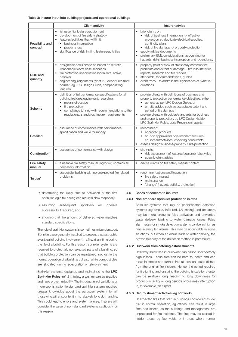
Table 3: Insurer input into building projects and operational buildings
Client activity Insurer advice
Feasibility and concept
• list essential features/equipment• development of fire safety strategy• features/activities that will limit:
• business interruption• property loss
• significance of risk limiting features/activities
• brief clients on:• risk of business interruption -> effective
protection eg duplicate electrical supplies, continuity plans
• risk of fire damage -> property protection• supply advice documents• preliminary EML considerations, accounting for
hazards, risks, business interruption and redundancy
QDR and quantify
• design/risk decisions to be based on realistic ‘reasonable worst case scenarios’
• fire protection specification (sprinklers, active, passive)
• engineering judgements (what if?, ‘departures from normal’, eg LPC Design Guide, compensating features)
• property point of view of statistically common fire problems and extent of damage - fire loss statistics, reports, research and fire models
• standards, recommendations, guides• event trees – to address the significance of ‘what if?’
questions
Scheme
• definition of full performance specifications for all building features/equipment, regarding:• means of escape• fire protection• compliance (or not) with recommendations to the
regulations, standards, insurer requirements
• provide clients with definitions of business and property protection performance objectives, either:• general as per LPC Design Guide, or • on-site advice such as acceptable extent and
period of fire damage• provide clients with guides/standards for business
and property protection, eg LPC Design Guide, LPC Sprinkler Rules, Loss Prevention reports
Detailed
• assurance of conformance with performance specification and value for money
• recommend:• approved products• ad-hoc approval for non-standard features/
equipment/activities, checking consultants• assess design business/property risks/protection
Construction• assurance of conformance with design • site visits:
• risk assessment of features/equipment/activities• specific client advice
Fire safety manual
• a useable fire safety manual (log book) contains all necessary information
• advise clients on fire safety manual content
‘In use’
• successful building with no unexpected fire related problems
• recommendations and inspection:• fire safety manual• maintenance• ‘change’ (hazard, activity, protection)
14 15
protection methods have been disabled because of the
type of refurbishment work being performed. Additionally,
the building may contain materials with little or no resistance
to fire and smoke damage, as no such requirement would
normally be necessary.
4.5.4 Unique equipment
Many businesses are highly dependent on one or two
specialised pieces of equipment (eg electronic facilities,
production equipment) for the functioning of the business.
Equally, some building facilities or decorative features,
eg escalators, marble facades, may be so unique that
replacement and/or reinstatement may require a couple of
years or may not be possible at all. Fires that damage such
equipment or features can lead to unacceptable periods of
business interruption.
4.5.5 Large retail stores/warehouses
Fires starting in large stores that contain a relatively high fire
load, if not extinguished or controlled in the early stages,
can quickly become massive fires. Such fires are almost
impossible for the fire service to fight and hence complete
loss of building and loss of the local business is likely.
4.5.6 Tunnels
Tunnels are constructed to solve logistical or environmental
difficulties and many communities become dependent
on them. Health and safety is of paramount importance
in the construction phases of tunnel designs, but during
its service life the ability of a tunnel plus services to
withstand fire are not always fully addressed. This can
result in protracted closures and downtime following a fire.
Reinstatement of a tunnel, after a fire incident, could be
relatively quick if at the design stage consideration is given
to both life safety and property protection objectives so
that ‘reasonable worst case scenarios’ could be selected
on this basis.
5. INSURER PARTICIPATION
5.1 Design stage – assistance
Insurers can offer advice to clients at all stages of the
design process, in advance of in-life management of a
building risk. In particular, insurers can assist clients and
fire safety engineers with the development of:
• property protection objectives (QDR) where this is
not just limiting damage to certain parts of a building
but also minimising the impact on a business due to
avoidable interruptions post fire;
• property protection acceptance criteria (QDR) –
specification of percentages of damage (number of
rooms) that would be deemed acceptable, and high
value areas (due to content or use) where extensive
damage would be unacceptable;
• reasonable worst case fire scenario, from a property
point of view – hazards and loss events that are known
to be common for the particular occupancy or client,
fire size (amount and type of combustibles that should
be considered in a quantification exercise), system
failures and consequences that should be considered
and time periods required for assessing the extent of
loss from a fire event;
• specification, checking and approval of active and
passive fire protection;
• specification, checking and approval of fire safety
manuals; and
• engineering judgements (what ifs? departures from
normal, eg LPC Design Guide, compensating features).
Table 3 shows the contributions an insurer can make at
each stage of the design process. Insurers are able to offer
assistance in these areas as they are supported by experts
and have access to:
• fire loss statistics;
• fire loss event reports;
• fire research;
• fire models;
• standards;
• recommendations;
• hazard/event scenarios of concern for loss; and
• checking consultants (design, fire protection systems –
with acceptable credentials).
5.2 Insurer evaluation of loss
An insurer will consider all aspects affecting a potential fire
loss. Factors include building, location, material, people,
activity, and management.
In the first instance, an insurer will not consider a fire safety
engineered designed building as a complete solution. Only
after proven application of insurer requirements for both
property protection and business interruption will benefits
of fire safety engineered designs be fully recognised
by insurers.
NML, EML and MFL will be determined following
consideration of building, the fire safety manual and the
FSE report. In particular, an insurer will
1) look for designs whose initial objectives set out to
minimise property and business losses;
2) assess design and management activities followed;
and
3) evaluate short- and long-term financial implications.
Fire safety engineers should be aware that some
building types might be deemed uninsurable due to
an unacceptable level of risk (eg some large composite
panel buildings).
When applying FSE to building design, early consultation
with an insurer can assist the client in ensuring the final
design is acceptable to an insurer.

14 15
6. CONCLUSIONS
• Fire safety engineered buildings tend to be prestigious and
thus large, well controlled risks. Hence, a reduced number of
fire incidents is anticipated. However, the problems of a large
fire event remain a possibility.
• The lack of numbers of fire safety engineered buildings, and
hence experience, makes estimation of loss difficult. Greater
use of engineered and hazard/consequence calculations will
be required.
• Fire safety engineering is a highly specialised discipline. It is the
application of scientific/engineering facts to design. It requires
extensive knowledge, data and fire modelling competency.
In addition, the professional qualification ‘chartered status’
and the ability to understand the criteria of the FSE study (ie
life safety and property conservation objectives) are essential.
• Early participation by insurers at the design stage when
applying fire safety engineering to building design will assist
the client by ensuring that the final design is acceptable to
an insurer.
• Quantification of FSE should consider the full period of a
possible fire event, from ignition to fire extinguishment, salvage
and clean up, for designs where property conservation is to
be considered.
• Conformance to the fire safety manual and ‘in use’ management
procedures (eg for ‘change of use’) will be essential for the
continuous acceptance by insurers of fire safety engineered
buildings.
• An emphasis on simple and reliable fire protection solutions
will be viewed favourably by insurers.
• Fire safety engineers need to be made aware that some
building types or fire safety engineered designs may result in a
building that is deemed uninsurable by insurers.
7. REFERENCES
1. Approved Document B, fire safety, the Building
Regulations, Department of the Environment and the Welsh
Office, 1992, The Stationery Office.
2. The Building Regulations 1991, SI 1991 No 2768 plus
amendments, The Stationery Office.
3. Fire safety engineering in buildings, BS DD 240, 1997,
British Standards Institution.
4. Approved Document B, fire Safety, the Building
Regulations, Department of the Environment and the
Regions, 2000, The Stationery Office.
5. BS 5588: Fire precautions in the design and construction
of buildings, various parts, British Standards Institution.
6. BDM1: FPA Design guide for the fire protection for
buildings: Essential principles, 2nd edition, 2007,
www.riscauthority.co.uk.
7. BS 7974: 2001: Application of fire safety engineering
principles to the design of buildings. Code of practice,
British Standards Institution.
8. Approved Document B, fire safety, buildings other than
dwellinghouses, incorporating insurer’s requirements for
property protection, Annex J, www.riscauthority.co.uk.
9. a) Health and Safety at Work etc Act 1974; b) Management of
Health and Safety at Work Regulations 1992; c) Workplace
(health, safety and welfare) Regulations 1992; d) Regulatory
Reform (Fire Safety) Order 2005, The Stationery Office.
10. Construction (Design and Management) Regulations 2007,
The Stationery Office.
11. Stephen M. Olenick and Douglas J. Carpenter, An updated
international survey of computer models for fire and
smoke, Journal of Fire Protection Engineering, Vol 13, May
2003, www.firemodelssurvey.com
12. BS 9999: 2008: Code of practice for fire safety in the
design, management and use of buildings, British
Standards Institution.
13. Fire Statistics Monitor, published annually. Communities and
Local Government.
14. Large Loss Fire Statistics, published quarterly, Fire Protection
Association/RISCAuthority.
15. Jackman L A and Humpheries T P, Fire safety document
for the example department store, use of the draft
British Standard code of practice for the application of
fire safety engineering principles, 1995, Loss Prevention
Council.
16. Jackman L A, Finegan M and Campbell S, LPR 17: Christmas
trees: fire research and recommendations, 2000, Fire
Protection Association.
17. Morris B and Jackman L A, LPR 11: Fire spread in multi-
storey buildings with glazed curtain wall facades, 1999,
Loss Prevention Council.
18. PD 7974-1: 2003: Application of fire safety engineering
principles to the design of buildings, initiation and
development of fire within the enclosure of origin
(Sub-system 1), British Standards Institution.
19. A conceptual approach towards a probability-based
design guide on structural fire safety, CIB W14 Workshop
Report, 1983.
20. Morgan H P, Ghosh B K, Garrad G, Pamlitschka R, De Smedt
J-C and Schoonbaert L, BR 368: Design methodologies
for smoke and heat exhaust ventilation, 1999, BRE.
21. LPC Rules for automatic sprinkler installations,
incorporating BS EN 12845, 2009, www.riscauthority.co.uk.

administered by
Fire Protection AssociationLondon Road, Moreton in MarshGloucestershire GL56 0RH, UKTel: +44 (0)1608 812500 Fax: +44 (0)1608 812501 Email: [email protected] Website: www.riscauthority.co.uk
2011 © The Fire Protection Association on behalf of RISCAuthority
Hard copies of this document may be obtained from the publications department of the FPA at the above address.
Electronic copies may be obtained from www.riscauthority.co.uk.
Printed by: xxxxxxxxxxxxxxxxxxxxxxxxxxxxxxxxxxxxxxxxxxxxx