first ohmic discharge assisted with rf power in …in this paper, we report the first ohmic...
TRANSCRIPT
Plasma and Fusion Research: Regular Articles Volume 6, 1402003 (2011)
First Ohmic Discharge Assisted with RF Power inQUEST Spherical Tokamak
Osamu MITARAI, Kazuo NAKAMURA1), Saya TASHIMA1), Makoto HASEGAWA1),Hiroshi IDEI1), Mizuki SAKAMOTO1), Kazuaki HANADA1), Hideki ZUSHI1), Kohnosuke SATO1),
Masaki ISHIGURO1), Hai Qing LIU1), Yuta HIGASHIZONO1), Aki HIGASHIJIMA1),Hisatoshi NAKASHIMA1), Shoji KAWASAKI1), Yuichi TAKASE2), Takashi MAEKAWA3)
and Nobuhiro NISHINO4)
Liberal Arts Education Center, Kumamoto Campus, Tokai University, 9-1-1 Toroku, Kumamoto 862-8652, Japan1)Research Institute for Applied Mechanics, Kyushu University, 6-1 Kasuga-koen, Kasuga 816-8580, Japan
2)Graduate School of Frontier Sciences and Graduate School of Science, University of Tokyo, Kashiwa 277-85611, Japan3)Graduate School of Energy Science, Kyoto University, Kyoto 606-8502, Japan
4)Department of Engineering, Hiroshima Univeristy, Higashi-Hiroshima 739-8527, Japan
(Received 23 October 2009 / Accepted 17 November 2010)
Ohmic plasma currents of up to 17 kA with a discharge duration of 0.32 s have been obtained in the KyushuUniversity Experiment with Steady-State Spherical Tokamak (QUEST) with the help of electron cyclotron wave(ECW) and cancellation coils (CCs). The CCs, originally installed to create a field null in the plasma breakdownphase, are essential for producing plasma current in QUEST. Although the ohmic coil current is initially biasedand then reduced completely to zero to induce the plasma current in 15-20 ms, we demonstrate that the flat topof the plasma current exceeding 20 ms is maintained by the vertical field after the ohmic current is switched off.This type of operation is quite favorable for extending pulsed operation to the steady state by electron Bernsteinwave current drive (EBCD).c© 2011 The Japan Society of Plasma Science and Nuclear Fusion Research
Keywords: spherical tokamak, current start-up, ohmic clamp, cancellation coil, ECW, vertical field
DOI: 10.1585/pfr.6.1402003
1. IntroductionPlasma current ramp-up has been recognized as
a major difficulty in low-aspect ratio spherical toka-maks (STs) [1] because of insufficient room for a centralsolenoid (CS) on the inboard side of the torus. A new con-cept has been proposed for ramping up the plasma currentusing vertical field and heating power [2, 3]; it was suc-cessfully demonstrated on the JT-60U tokamak [4–6] andthe TST-2 [7] and MAST [8] STs. However, as steady statewas not maintained in these experiments, an experimentaldemonstration of steady-state operation in an ST is neces-sary.
On the other hand, “ohmic clamp” experiments arebasic experiments related to plasma current ramp-up byvertical field that is sometimes conducted in the initialphase of experiments of this type because of their rela-tively simple setup [4, 9]. In these experiments, the ohmiccoil current is kept constant and heating power is applied.Any plasma current ramp-up during the “ohmic clamp”phase may be due to the vertical field effect because thenon-inductive drive method usually needs longer time toshow its effect [4]. The first “ohmic clamp” experimentsin an ST were performed in National Spherical Torus Ex-
author’s e-mail: [email protected]
periment (NSTX) [10]. However, the plasma current wasnot sufficiently ramped up to demonstrate its effect. Thereasons are discussed in a previous paper but are not yetclear [10]. On the other hand, in the newly operationalQUEST machine, ohmic discharge assisted with RF powercorresponds exactly with the “ohmic clamp” experimentsdescribed in this paper. Here, we demonstrate that theplasma current can be ramped up by the vertical field effectin the QUEST tokamak.
The QUEST tokamak has been designed to achievesteady-state operation with a plasma current ≥20 kA byusing electron Bernstein wave current drive (EBCD) andto study plasma-wall interactions in high-temperature(∼500◦C) environments [11]. Experimental operating sce-narios can be categorized as (1) pure ohmic discharge, (2)ohmic and RF current drive, (3) pure RF start-up to thesteady state, and (4) vertical-field-assisted plasma currentstart-up and RF current drive to the steady state.
To start up the plasma current in a tokamak, twomethods are used to create a poloidal field (PF) null inthe plasma region. The first is to use PF coils, suchas the shaping vertical field coil (PF26 coil in QUEST)and divertor coils, to reduce the stray field from theohmic transformer. However, as the initial current di-
c© 2011 The Japan Society of PlasmaScience and Nuclear Fusion Research
1402003-1
Plasma and Fusion Research: Regular Articles Volume 6, 1402003 (2011)
rection of PF26 coil produces an opposite vertical fieldto the equilibrium field, its current polarity should bequickly changed for equilibrium control, which requiresa high-voltage bi-directional circuit. This method isused in NSTX, for example [12]. In several other op-erational or planned tokamaks worldwide, such as Alca-tor C-MOD [13], EAST [14], KSTAR [15], ITER [16], andJT-60SA [17], well-predicted preprogrammed control ofmany PF coil currents is or will be used to create a fieldnull regime and a subsequent plasma shape, which are es-sential for this method.
The second method for creating a field null regimeis to use additional cancellation coils (CCs) to reducethe stray field from the ohmic transformer. Because theohmic transformer and the CCs are connected in series,the power supply circuit cost can be reduced and no rip-ple effect appears even if one is present in the power cir-cuit. Therefore, the operation is simpler than the firstmethod, even during the flat-top phase, because verticalfield control does not depend on the ohmic transformercurrent. This second method has been used in ASDEXUpgrade [18], DIII-D [19], JT-60U [20], TRIAM-1M [21],TST-2 [22], and Globus-M [23], and will be used in theSST-1 [24] and KTM [25] tokamaks.
In this paper, we report the first ohmic discharge us-ing an ohmic transformer and CC assisted with RF power.A flat top of a 17-kA plasma current and a 320 ms dura-tion has been achieved in the first experimental campaign.Although the ohmic pulse duration is very short, a muchlonger discharge duration has been obtained because of thevertical field induction effect. In QUEST, the induction du-ration of the ohmic current is presently as short as 20 msbecause of power supply circuit limitations. After 20 ms,the ohmic current is switched off and becomes zero, whichcorresponds to the “ohmic clamp” experiments. This typeof scenario with “ohmic clamp” discharge assisted with RFpower is favorable for future steady-state operation withRF current drive.
2. Experimental LayoutIn QUEST, the major radius is R ∼ 0.68 m, the mi-
nor radius is a ≤ 0.40 m, the elongation is κ ≤ 1.8, andthe toroidal field is Bt ≤ 0.5 T. A launcher for electroncyclotron waves (ECWs), designed for electron Bernsteinwave (EBW) heating at a frequency of 8.2 GHz, is installedon the outboard side of the torus in QUEST. The cut-offdensity for the O-mode is 0.83 × 10¹⁸ m−3.
In QUEST, CCs are connected in series to the ohmiccoil to reduce the poloidal stray field from the ohmic trans-former during the breakdown phase, as shown in Fig. 1. Asthe power supply circuit is modified from that of the high-aspect ratio tokamak TRIAM-1M, the current waveform ofthe PF26 vertical field coil is not fully controllable. Evenif the waveform is controlled, a large current ripple in thePF26 vertical field coil power supply may not be able to
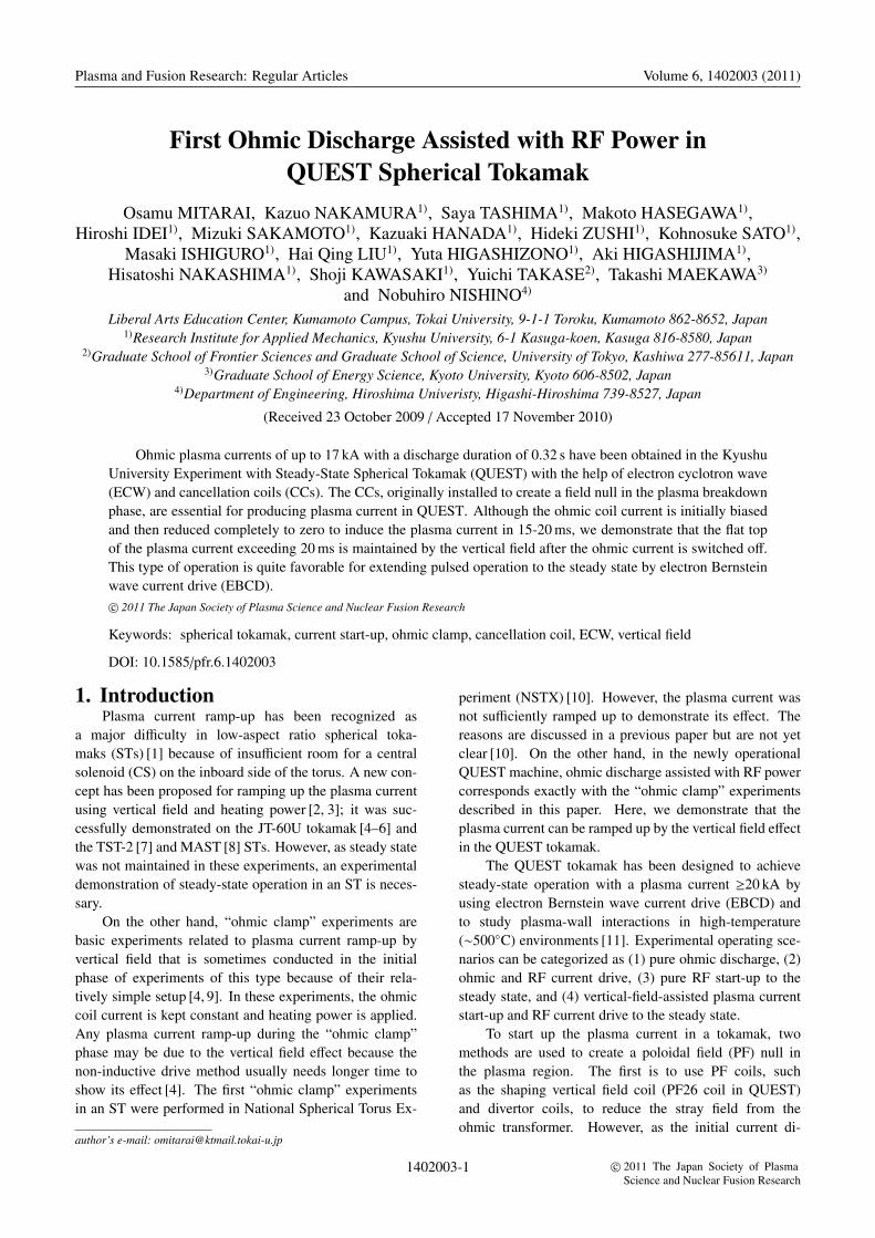
Fig. 1 Magnetic field strength and the location of poloidal fieldcoils in QUEST for ICS = 8 kA and IPF26 = 0 kA. Greenregimes indicate the vertical field opposite to the equilib-rium field.
reduce the stray field from the ohmic coil. An additionalCC (with a maximum of four turns) can cancel the poloidalstray field from the ohmic coil, as shown in Fig. 1. How-ever, the best position for the CC is already occupied byother equipment and only the space outside of the PF17coils is available.
A CC with one turn was selected to create a small fieldnull region in the central area of the vacuum chamber, asshown in Fig. 1. However, with a weak toroidal field ofBt = 0.14 T at R = 0.68 m in the first phase of the experi-ments, the resonant position of 8.2 GHz RF was at 33 cm.This position is in the inward regime and outside of thenull field regime, but in the higher ohmic induction elec-tric field regime. Plasma current start-up from the inwardposition has a smaller plasma inductance, which is suitablefor ramping up the plasma current.
3. Experimental Results3.1 Initial discharges
At the second shot after starting the ohmic dischargeexperiments, a short pulse of plasma current up to ∼3.5 kAwas produced (#1448); this increased to ∼8.5 kA after fourshots (#1452) and then suddenly a long discharge of 10 kAand ∼250 ms (#1456) was obtained, as shown in Fig. 2.The long discharges can be reproduced by adjusting thevertical magnetic field by using PF26 coils to optimize theplasma current. Plasma cross section images taken by afast TV camera are shown in Fig. 3.
In the reproducible discharges, vertical field is ap-plied during the breakdown phase. A typical applied ver-tical field is 74 G (IPF26 = 0.25 kA in Fig. 5 (c)) at R =0.68 m. Therefore, as shown in the calculated magneticfield strength distribution in Fig. 4, a wide null regime
1402003-2

Plasma and Fusion Research: Regular Articles Volume 6, 1402003 (2011)
Fig. 2 Plasma current evolution at second (#1448), fifth(#1452), and tenth shots (#1456) on the first day ofOhmic discharge experiments in QUEST.
Fig. 3 Fast TV camera images of initial plasma current start-upphase of first long ohmic discharge in QUEST. (#1456)
disappears when the vertical field is applied. Note thatthe vertical field induced by the vacuum chamber currentis negligible at the breakdown phase because the vacuumchamber current crosses zero, as seen later in Figs. 6, 8, and13. However, two small null points remain at z ∼ ±0.47 mand at the resonant line, as indicated by the dashed line inFig. 4, although their role is unclear.
3.2 Larger ohmic coil bias current of ICS =8 kA
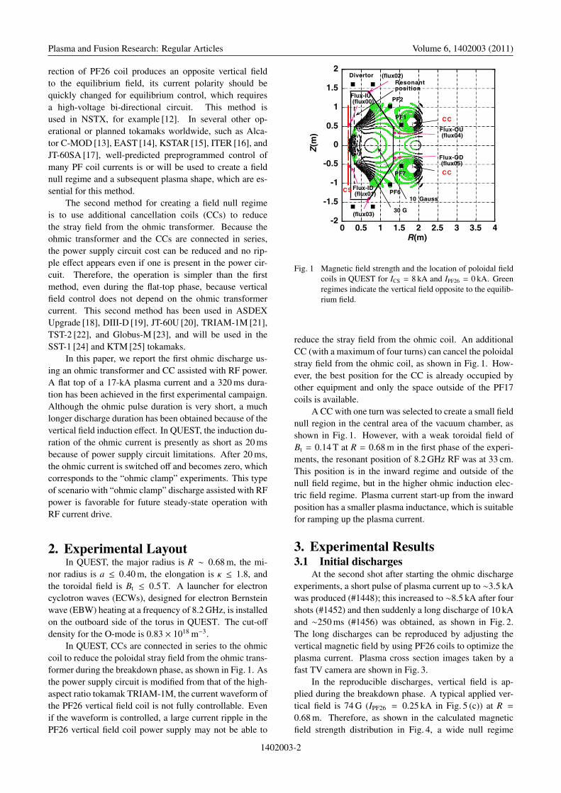
After careful adjustments of the vertical field, aplasma current of up to 15 kA (#1932) was obtained. Theoverall discharge waveforms of various parameters areshown in Fig. 5. As shown in Fig. 5 (h), RF power wasapplied from 0.4 s to 0.56 s, and the ohmic coil currentwas increased to 8.3 kA for biasing and ramped down to
Fig. 4 Magnetic field strength for ICS = 8 kA and IPF26 =
0.25 kA. Green regimes indicate the vertical field oppo-site to the equilibrium field.
zero at 0.5 s for inducing the plasma current (Fig. 5 (b)),as performed in standard ohmic discharge operation in atokamak. The plasma current starts at t = 0.48 s and in-creases to ∼10 kA in 20 ms with two bumps; it then slowlyincreases to 15 kA after the ohmic coil current becomeszero. A vertical field was applied at the breakdown phase;therefore, the null field regime is not created in an actualdischarge, as shown in Fig. 4. For a PF26 coil current ofIPF26 ∼ 0.3 kA, the estimated vertical field is Bv ∼ 137 Gat the resonant position.
The flux measured on the ohmic transformer is∼0.08 Vs (see Fig. 5 (f)), which is close to the estimatedvalue using the axial strength of the magnetic field fromthe ICS current, as Φ = πr2Bz = 0.073 Vs. The resistiveflux is ΦR = CEμoRIp ∼ 0.006 Vs for an Ejima coefficientCE = 0.7, R = 0.68 m, and Ip = 10 kA. Because the in-ductive flux is estimated to be LpIp = 0.6 × 10−6 × 104 ∼0.006 Vs, the total flux is 0.012 Vs, which is much smallerthan the measured flux. This indicates that most of the cur-rent is flowing in the vacuum chamber, as described below.
A more detailed waveform for the plasma positionis shown in Fig. 6 (e). While the ohmic transformer cur-rent is terminated at 0.5 s, the vertical field increases withIPF26 and reaches the maximum at t ∼ 0.595 s (Fig. 6 (f)).The plasma current becomes maximum at almost the sametime. The loop voltage measurements (Fig. 6 (g)) suggestthat the vertical field increment creates this loop voltageand induces the plasma current after ohmic coil currenttermination. A loop voltage of less than 1.2 V was actu-ally applied before the plasma current peak. Figure 6 (c)shows the fluxes representing the sum of the vacuum cham-ber and plasma currents, which are obtained from the mea-sured fluxes at the inner and outer positions (Flux00 andFlux04, respectively, in Fig. 5 (f)). Here the fluxes from the
1402003-3
Plasma and Fusion Research: Regular Articles Volume 6, 1402003 (2011)
Fig. 5 Plasma current evolution in QUEST at Bt = 0.14 T with one-turn cancellation coil. (a) Plasma current, (b) CS current, (c) PF26vertical shaping coil current and set value, (d) PF17 vertical field coil current, (e) loop voltage measured at three locations, (f) fluxmeasured at three locations, (g) oxygen impurity line, and (h) 8.2 GHz RF power. (#1932)
ohmic transformer and the PF26 and PF17 coils are sub-tracted from the measured flux (Φ(measured)) upon con-sideration of the coil current polarity, and then the final flux(Φ(Ip + IVC) in Fig. 6 (c)), which is the sum of the fluxesfrom the vacuum chamber current IVC induced by all thepoloidal coils and the plasma current Ip, is given by
⎧⎪⎪⎪⎪⎪⎪⎨⎪⎪⎪⎪⎪⎪⎩
ΦIU(Ip + IVC) = ΦIU(measured) −ΦIU−CS
−ΦIU−PF26 −ΦIU−PF17
ΦOU(Ip + IVC) = ΦOU(measured) −ΦOU−CS
−ΦOU−PF26 −ΦOU−PF17
where the fluxes between the two flux loops and the PFcoils are given by
ΦIU−CS = −10.09 × 10⁻³ICS(kA),
ΦIU−PF26 = +4.4127 × 10⁻³IPF26(kA),
ΦIU−PF17 = +9.345 × 10⁻³IPF17(kA),
ΦOU−CS = −10.05 × 10⁻³ICS(kA),
ΦOU−PF26 = +148.55 × 10⁻³IPF26(kA), and
ΦOU−PF17 = +54.98 × 10⁻³IPF17(kA).
Here, the subscripts “IU” and “OU” indicate the inner up-per and outer upper flux loops, respectively. Because theestimated values in Fig. 6 (c) are based on both measuredand calculated values for the PF coil currents, they are sen-sitive to coil position errors.
The inner flux (INFLUXVP) and the outer flux (OUT-FLUXVP) cross zero when the ohmic coil bias current sat-urates, as shown in Fig. 6 (c). Plasma breakdown was ex-pected to occur in this phase because of the negligible vac-uum chamber current effect. In the plasma current ramp-up
phase, because of the ramp-down of the ohmic coil current,the vacuum chamber currents flow in the same direction asthe plasma current. After the ohmic coil current is reducedto zero, the vacuum chamber current still flows and is even-tually damped away later.
Furthermore, the delay time effects due to the vacuumchamber on the flux loop from the ohmic, PF26, and PF17coil currents have been taken into account in the plasmaposition measurements. For example, two time constantsof 1.17 s and 8.49 s were obtained for the inner upper flux(Flux00) in separate discharges without the plasma current,and values of 9.46 s and 13.5 s were obtained for the outerupper flux (Flux04); these values were used for conver-sion from the ohmic coil current. The fluxes ΦOU−CS−VC,ΦOU−PF26−VC, and ΦOU−PF17−VC, with the vacuum cham-ber effect obtained in this way, were subtracted from themeasured values, yielding the flux from the plasma currentalone, as shown in the following relationships.
⎧⎪⎪⎪⎪⎪⎪⎨⎪⎪⎪⎪⎪⎪⎩
ΦIU(Ip) = ΦIU(measured) −ΦIU−CS−VC
−ΦIU−PF26−VC −ΦIU−PF17−VC
ΦOU(Ip) = ΦOU(measured) −ΦOU−CS−VC
−ΦOU−PF26−VC −ΦOU−PF17−VC
Here, the subscript “VC” indicates the vacuum chambereffect. Figure 6 (d) shows the fluxes from the plasma cur-rent alone. The signal before plasma breakdown is almostcanceled out. Note that because the estimated values inFig. 6 (d) are based on all the measured values, they are notaffected by coil position errors.
In Fig. 6 (e), the plasma position was derived fromthese two fluxes in Fig. 6 (d). Up-down symmetry was as-
1402003-4

Plasma and Fusion Research: Regular Articles Volume 6, 1402003 (2011)
Fig. 6 Detailed versions of waveforms in Fig. 5. (a) Plasma cur-rent, (b) CS current, (c) flux consisting of vacuum cham-ber current and plasma current [red: outer flux (Flux04);black: inner flux (Flux00)], (d) flux due to plasma cur-rent alone [red: outer flux (Flux04); black: inner flux(Flux00)], (e) plasma position, (f) PF26 and PF17 coilcurrents, and (g) loop voltage measured at Flux02 and04 positions. Third vertical line marks zero loop voltage.(#1932)
sumed because the up and down fluxes do not differ, andthe fast camera shows no upward shift in the plasma cur-rent. Using the least square method, for the fluxes obtainedin Fig. 6 (d), and the single current loop approximation, theplasma position was calculated as shown in Fig. 6 (e). Be-cause the plasma position before the vacuum chamber cur-rent decay (t < 0.52 s) may not be accurate, that phase isomitted in this analysis. The plasma position is approxi-mately around R ∼ 0.72 m at t ∼ 0.6 s and gradually shiftsinward. For this parameter, the inner plasma’s minor radiusis a ∼0.50 m because the plasma is limited by an inner lim-iter placed at 0.22 m. An almost circular plasma is formedwith an aspect ratio of A ∼ 0.72/0.50 ∼ 1.44, and the edgesafety factor could be estimated as q ∼ 5a2Bt/RIp ∼ 16.Note that because the plasma edge cannot be seen by the
TV camera during the full plasma current phase owing tothe low density, a cross check of the plasma position awaitshigher-density operation. Although we used only two fluxloops, several flux loops are expected to provide a plasmaboundary in the near future by using the Cauchy conditionsurface (CCS) method [26]. Therefore, the above estima-tion of the plasma position is only tentative and is not yetaccurate.
As the circuit parameters of the shaping and verticalfield coils (PF26 and PF17, respectively) have been setfor long-duration steady-state operation in this first exper-imental campaign, a quick response to match the plasmacurrent ramp-up in 20 ms is not possible, leading to theearly application of the vertical field coil current. In ad-dition, because the coupling between the ohmic coil andthe PF26 (Fig. 5 (c)) and PF17 (Fig. 5 (d)) coils are quitestrong, these coil currents are induced unintentionally be-cause of the fact that the switches in these circuits are al-ready on owing to the present circuit limitation. Furtheroptimization of these circuit parameters would increase theplasma current.
3.3 Smaller ohmic coil bias current of ICS =5 kA
To decrease the coil coupling and optimize the ohmictransformer current, the ohmic coil bias current was re-duced to ICS = 5 kA; the results are shown in Fig. 7. TheRF application time was delayed and was shorter than thatin Fig. 5. Therefore, the initial negative plasma currentwas not induced. The resulting plasma current evolution issmoother, and a slightly larger and longer plasma currenthas been obtained by applying a longer and larger verti-cal field. This is the best discharge waveform in the firstohmic discharge experimental campaign. As the ohmiccoil bias current ICS is reduced, the coupling between thePF26 and PF17 coils decreases, as seen in Fig. 7 (d). Whenthe bias current ICS is further reduced to 4 kA, the couplingbetween the PF26 and ohmic transformer coils decreases,and a plasma current is successfully established.
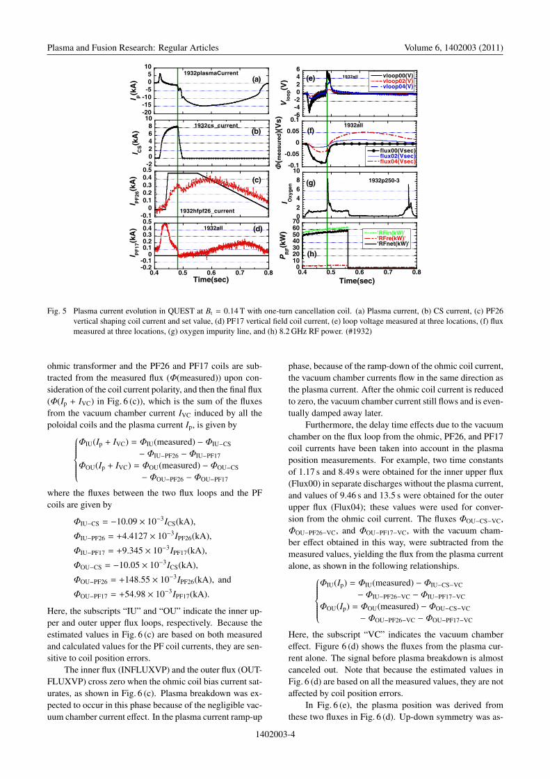
Figure 8 shows more detailed waveforms. Becausethe loop voltage is also positive until the plasma currentpeak, it is clearly understood that the vertical field drivesthe plasma current for a long time after the ohmic coilcurrent is switched off, which was also done previously.The fluxes from the plasma and vacuum chamber currentsand from the plasma current alone are shown in Figs. 8 (c)and 8 (d), respectively. The plasma position remains sta-ble at around 0.7 m for a long time in the outward posi-tion with a better n-index area. A plasma position that re-mains in the stable regime with a positive n-index, definedas n = −R/Bv(dBv/dR), may yield a longer plasma currentwithout feedback control.
A fast TV camera monitored the plasma cross sec-tion and position only in the early phase starting 3 ms afterplasma current start-up, as shown in Fig. 9. The plasma
1402003-5

Plasma and Fusion Research: Regular Articles Volume 6, 1402003 (2011)
Fig. 7 Plasma current evolution in QUEST at Bt = 0.14 T with smaller ohmic transformer bias current. (a) Plasma current, (b) CS current,(c) PF26 vertical shaping coil current and set value, (d) PF17 vertical field coil current, (e) loop voltage measured at three locations,(f) flux measured at three locations, (g) oxygen impurity line, and (h) 8.2 GHz RF power. (#1966)
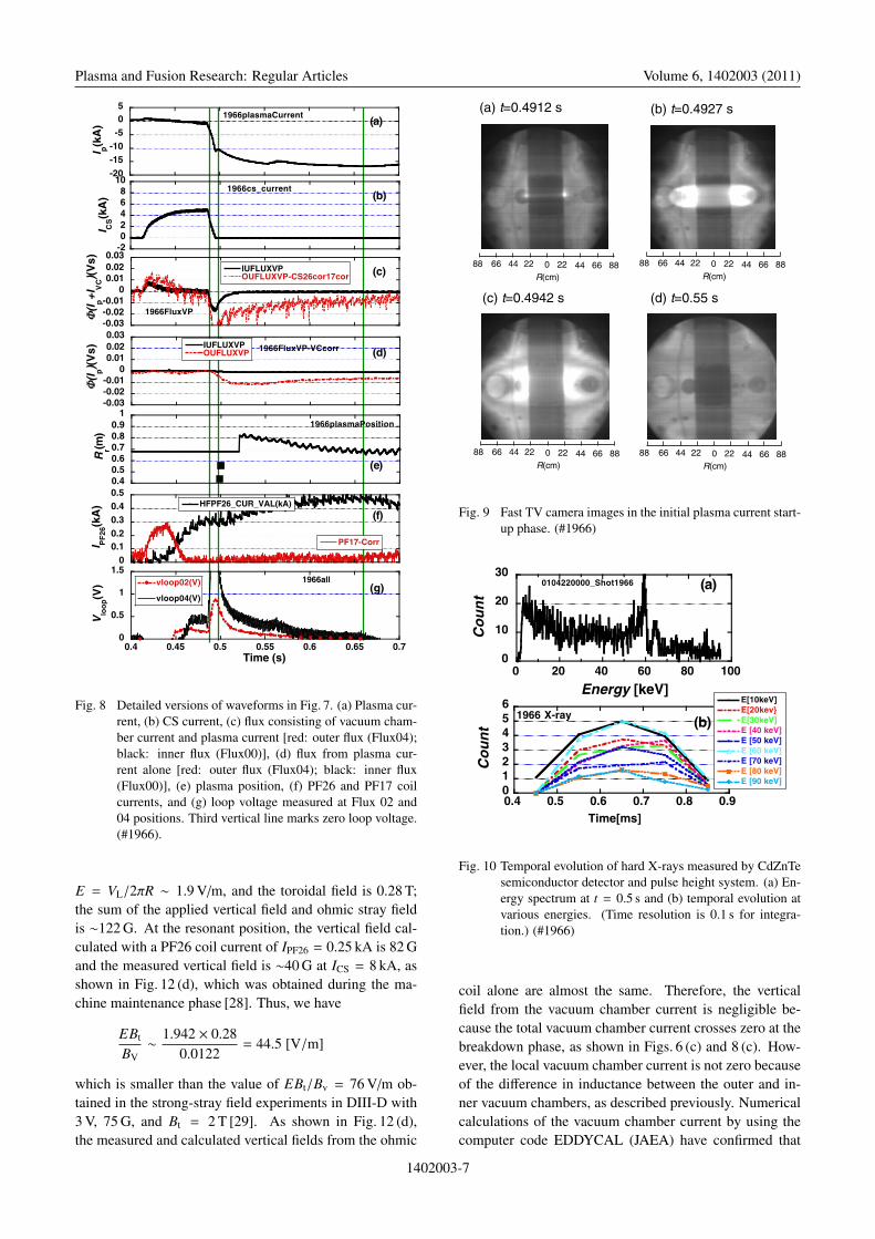
current seems to start on the central ohmic transformerof R ∼ 0.23 m at t = 0.4912 s and expands outward toR ∼ 0.44 m at t = 0.4927 s; a closed flux surface is clearlyseen at 0.4942 s. The radius of the central toroidal lim-iter (0.22 m) suggests that the center of the plasma’s crosssection is at around R = 0.55 ∼ 0.6 m at t = 0.4942 s.After this, the plasma boundary is unclear; for example, att = 0.55 s (Fig. 9 (d)), the plasma boundary is not visiblebecause of the low-density operation. Because the plasmaposition in the later phase is at around R ∼ 0.70 m, as mea-sured by the two flux loops, the plasma initially moves out-ward and then remains at a stable position. Because thepositions obtained by these two methods do not overlap,an accurate comparison cannot be made in this situation.
Although density measurements were performed us-ing reflectometry, it was difficult to determine the densitybecause of the small number of fringes. In the near fu-ture, a 2-mm interferometer will be available to measurethe density. However, hard X-ray measurements of up to100 keV using a CdZnTe semiconductor detector, as shownin Fig. 10 (a) at t = 0.5 s, suggest that the density couldbe low. The detector is placed on QUEST’s equatorialplane and views the forward emission from runaway elec-trons tangentially; the energy range is limited to 100 keVin this experiment. Runaway electrons with various ener-gies were created after ohmic coil current decay, as shownin Fig. 10 (b), where the time resolution is as large as 0.1 s.This may be due to acceleration by the vertical field induc-tion effect. The times required to reach the peak values ofthe plasma current and hard X-rays are almost the same,
0.65 s.When the vertical field drives the plasma current, ad-
ditional heating power is necessary to prevent the plasmacurrent from shifting inward [2]. However, in this QUESTexperiment, no additional heating power was applied dur-ing the vertical field current ramp-up phase. The electricfield, created during plasma current ramp-up by the ver-tical field, accelerates the electrons to higher energies, asshown in Fig. 10 (b). This increases the plasma energy, bal-ancing the inward force of the vertical field. Thus, this newmechanism for ramping up the plasma current without ad-ditional heating power may work only in the low-densityregime.
4. Discussions and SummaryThe operational waveform achieved here is suitable
for the future steady-state operation in QUEST becausethe ohmic transformer is already switched off. If the den-sity is below the cut-off value, electron cyclotron currentdrive (ECCD) can sustain the plasma current. If the den-sity is higher than the cut-off value, EBCD would drive theplasma current by using the new EBCD antenna configura-tion [27], as shown schematically in the operation scenarioin Fig. 11.
In the present discharges, no plasma breakdown oc-curs without RF power. Thus, we see that RF power con-tributes to the breakdown and the plasma current formationis quite reproducible. At the resonant position of 0.33 m inthis case, the loop voltage is VL ∼ 4 V, the electric field is
1402003-6
Plasma and Fusion Research: Regular Articles Volume 6, 1402003 (2011)
Fig. 8 Detailed versions of waveforms in Fig. 7. (a) Plasma cur-rent, (b) CS current, (c) flux consisting of vacuum cham-ber current and plasma current [red: outer flux (Flux04);black: inner flux (Flux00)], (d) flux from plasma cur-rent alone [red: outer flux (Flux04); black: inner flux(Flux00)], (e) plasma position, (f) PF26 and PF17 coilcurrents, and (g) loop voltage measured at Flux 02 and04 positions. Third vertical line marks zero loop voltage.(#1966).
E = VL/2πR ∼ 1.9 V/m, and the toroidal field is 0.28 T;the sum of the applied vertical field and ohmic stray fieldis ∼122 G. At the resonant position, the vertical field cal-culated with a PF26 coil current of IPF26 = 0.25 kA is 82 Gand the measured vertical field is ∼40 G at ICS = 8 kA, asshown in Fig. 12 (d), which was obtained during the ma-chine maintenance phase [28]. Thus, we have
EBt
BV∼ 1.942 × 0.28
0.0122= 44.5 [V/m]
which is smaller than the value of EBt/Bv = 76 V/m ob-tained in the strong-stray field experiments in DIII-D with3 V, 75 G, and Bt = 2 T [29]. As shown in Fig. 12 (d),the measured and calculated vertical fields from the ohmic
Fig. 9 Fast TV camera images in the initial plasma current start-up phase. (#1966)
Fig. 10 Temporal evolution of hard X-rays measured by CdZnTesemiconductor detector and pulse height system. (a) En-ergy spectrum at t = 0.5 s and (b) temporal evolution atvarious energies. (Time resolution is 0.1 s for integra-tion.) (#1966)
coil alone are almost the same. Therefore, the verticalfield from the vacuum chamber current is negligible be-cause the total vacuum chamber current crosses zero at thebreakdown phase, as shown in Figs. 6 (c) and 8 (c). How-ever, the local vacuum chamber current is not zero becauseof the difference in inductance between the outer and in-ner vacuum chambers, as described previously. Numericalcalculations of the vacuum chamber current by using thecomputer code EDDYCAL (JAEA) have confirmed that
1402003-7

Plasma and Fusion Research: Regular Articles Volume 6, 1402003 (2011)
Fig. 11 Operation scenario for steady-state EBCD operation.
Fig. 12 Measured vertical field inside vacuum chamber for ICS =
8 kA. (a) Ohmic coil current, (b) measured mag-netic fields Bv at various positions, (c) loop voltages(#2100) [29], and (d) measured and calculated Bv profilesat ICS = 8 kA.
Fig. 13 Calculated vertical field inside vacuum chamber for ICS =
8 kA. (a) Total magnetic field, (b) magnetic field fromohmic coil current without the effect of the vacuum cham-ber, (c) magnetic field produced by vacuum chamber cur-rent alone [29], and (d) vacuum chamber current densitiesin various chamber positions on upper vacuum chamberat 65 ms.
while the vertical field from the vacuum chamber currentalone crosses zero at the breakdown phase, as shown inFig. 13 (c), the local vacuum chamber current is not zero.At 65 ms, as shown in Fig. 13 (d), the inner vacuum cham-ber current reverses its polarity earlier but the outer vac-uum chamber current keeps flowing in the same direction.
Because the reliable breakdown criterion is EBt/Bv ∼1000 V/m in a stray vertical field environment [28, 30], theobtained value is quite low. The connection length is quiteshort, L ∼ aeffBt/Bv = (0.33−0.22)×0.28/0.0122 = 2.5 m,corresponding to 1.2 turns at the resonant position in thetoroidal direction. Here, aeff is defined as the distance fromthe resonant position to the inside limiter.
The runaway electrons created by the vertical fieldmay lead to a high-energy electron tail distribution func-tion, which is also favorable for EBCD. Heating poweris not applied during the “ohmic clamp” phase, but theplasma current is ramped up. This may be due to the accel-
1402003-8

Plasma and Fusion Research: Regular Articles Volume 6, 1402003 (2011)
eration of the runaway electrons by vertical field induction.However, further experiments and theoretical calculationsare needed to explain this result.
The PF26 coil current waveforms during the plasmacurrent ramp-up phase in shots #1932 and #1966 are differ-ent, as seen in Figs. 5 (c) and 7 (c). Because the PF26 coilcurrent decreases from 0.3 to 0.25 kA owing to the strongcoil coupling at ICS = 8 kA, the plasma current has bumps.This is because both cases have similar plasma currents;however, the equilibrium field is smaller in #1932 and sothe plasma current ramp-up is not smooth. Therefore, itis important to reduce the coil coupling for better plasmacontrol.
We achieved a plasma current of only 17 kA, whichis lower than the target value. A slower ohmic current de-cay would increase the plasma current. Smaller inductancein the vertical field coil with a half turn number would al-low easier plasma position equilibration than that in thepresent discharge during plasma current ramp-up, whichalso leads to a larger plasma current. Feedback control, inturn, plays an important role in achieving a larger plasmacurrent, longer pulse, and steady-state operation, and is un-der development using the CCS method [26].
We have described the initial ohmic discharge exper-iments in QUEST assisted with RF heating power. Wedemonstrated that the CC was very efficient and reliablein generating a plasma current in the early phase of theohmic discharge experiments, as expected, although thenull field regime was not created because a vertical fieldwas applied in the breakdown phase. Therefore, the RFpower strongly assisted this ohmic discharge start-up. Theinitial discharge waveform is very suitable for achievingthe future steady-state operation by ECCD or EBCD be-cause the ohmic coil current is already switched off and iszero in the early phase, in which the vertical field drives theplasma current during the zero phase of the ohmic trans-former current and facilitates the transition from the ohmicphase to the steady-state phase. This “ohmic clamp” exper-iment demonstrates that a vertical field without any heatingpower can ramp up the plasma current. Genuine CS-lessoperation using vertical field coils is also planned for thefuture steady-state operation, which is crucial in the futureST operation.
This work was performed with the support and un-der the auspices of the NIFS bi-directional collaborativeresearch program (NIFS07KUTR020).
[1] Y-K M. Peng et al., Fusion Technol. 30, 1372 (1996).[2] O. Mitarai, Plasma Phys. Control. Fusion 41, 1469 (1999).
[3] O. Mitarai and Y. Takase, Fusion Sci. Technol. 43, 67(2003).
[4] O. Mitarai, R. Yoshino and K. Ushigusa, Nucl. Fusion 10,1257 (2002).
[5] Y. Takase et al., J. Plasma Fusion Res. 78, 717 (2002).[6] S. Shiraiwa et al., Phys. Rev. Lett. 92, 035001 (2004).[7] O. Mitarai, Y. Takase, A. Ejiri, S. Shiraiwa et al., J. Plasma
Fusion Res. 80, 549 (2004).[8] A. Sykes et al., in 19th IEEE/NPSS Symposium on Fusion
Engineering (SOFE) (Atlantic City, USA, January 22-25),(2002) p.125.
[9] M. Ushigome, S. Ide, S. Itoh, E. Jotaki, O. Mitarai, S.Shiraiwa, T. Suzuki, Y. Takase et al., Nucl. Fusion 46, 207(2006).
[10] O. Mitarai, C. Kessel and A. Hirose, JEEE 129, No.9, Sec.A, 605 (2009).
[11] K. Hanada et al., in 22nd IAEA Fusion Energy Conference,(13-8, Oct. 2008, Geneve, Switzerland) FT/P3-25.
[12] C. Neumeyer et al., Fusion Eng. Des. 54, 275 (2001).[13] J.J. Ramos, MIT Plasma Fusion Center report PFC/RR-88-
9 (1988).[14] B.J. Xiao, D.A. Humphreys et al., Fusion Eng. Des. 83, 181
(2008).[15] J.A. Leuer, N.W. Eidiettis et al., General Atomic report
GA-A26492 (July 2009); Yeong-Kook Oh et al., FusionEng. Des. 83, 181 (2008).
[16] Y. Gribov et al., in chapter 8: Plasma Operation and Con-trol, Nucl. Fusion 47, S385 (2007).
[17] M. Matsukawa et al., in Asia Plasma and Fusion Associa-tion (APFA) Conference (Oct 27-29. 2009, Aomori, Japan)P27p1-17.
[18] W. Køppendørfer et al., Nucl. Eng. Des./Fusion 3, 265(1986).
[19] S. Kinoshita et al., General Atomic report GA-A19584,(Dec. 1989).
[20] R. Yoshino et al., Fusion Eng. Des. 24, 375 (1994).[21] K. Nakamura, Private communications (2010 March 25)
because of no official documentation.[22] S. Shiraiwa, “A study of electron Bernstein wave heating
for diagnostics and heating of spherical tokamak plasmas”,PhD theses (Univ. of Tokyo, April 27, 2007).
[23] V.K. Gusev et al., Nucl. Fusion 41, 919 (2001).[24] Y.C. Saxena and SST-1 Team, Nucl. Fusion 40, 1069
(2000).[25] V.A. Korotkov et al., Fusion Eng. Des. 56-57, 831 (2001).[26] K. Kurihara, Fusion Eng. Des. 51-52, 1049 (2000).[27] H. Idei et al., “Ray tracing and Fokker-Plank analyses
for electron Bernstein wave heating and current drive inQUEST”, ICCP 2009 (Fukuoka).
[28] O. Mitarai, K. Nakamura et al., J. Plasma Fusion Res. SE-RIES 9, 100 (2010); in Asia Plasma and Fusion Associa-tion (APFA) Conference (Oct 27-29. 2009, Aomori, Japan)P27p2-01.
[29] B. LLoyd et al., Nucl. Fusion 31, 2031 (1991).[30] V. Erkman and U. Gaspanrino, Plasma Phys. Control. Fu-
sion 36, 1869 (1994).
1402003-9