first draft of the opera specification version 2nemo/plc/refs/op2_d27_first draft of the... ·...
TRANSCRIPT
Work Package: WP5
Activities: 5.1
Type of document: Report
Date: 04 June 2007
IST Integrated Project No 026920 Partners:
CTI, DS2, EDEV CPL / EDF Group, Iberdrola, SEPC, TUD, URL
Responsible: EDEV CPL / EDF Group
Circulation: Public Confidential Restricted
File name: OP2_WP5_D27 Version: 1.0
Title: First draft of the OPERA specification version 2
D27 : FIRST DRAFT OF THE OPERA SPECIFICATION VERSION 2
Copyright
© Copyright 2007 The OPERA Consortium
Work Package: WP5
Type of document: Report
Date: 04 June 2007
EC/IST FP6 Project No 026920 File name: OP2_WP5_D27 Version: 1.0
Title: First draft of the OPERA specification version 2
Document History
Vers. Issue Date Content and changes
1.0 04.06.07 Creation of the first version of the document
Document Authors
Partners Contributors
CTI Manu Sharma
DS2 Luis Manuel Torres, Salvador Iranzo, Marcos Martinez, Serafin Arroyo
EDEV CPL / EDF Group Laurent Feltin, Eric Perrier
Iberdrola Inigo Berganza
SEPC Philippe Conq
TUD Le Phu Do
University Ramon Llull (URL)
Guiomar Corral, Josep M. Selga
Document Approvers
Partners Approvers
EDEV CPL / EDF Group Laurent Feltin

4-June-07 P1901_PRO_016_r0
Submission page 1 UPA-OPERA
IEEE P1901 Draft Standard for Broadband over Power Line Networks: Medium Access Control and Physical Layer Specifications
Proposal for the IEEE 1901 Access Power Line Networks Standard
Date: 2007-06-04
Author(s): Name Company Address Phone email
Laurent Feltin OPERA EDEV CPL Technologie 1 avenue du Général de Gaulle 92140 Clamart, France
+33 1 41 33 95 14 [email protected]
Inigo Berganza OPERA Iberdrola S.A. Avda San Adrián 48 48003 Bilbao, Spain
+34 944665525 [email protected]
Luis M. Torres OPERA
Design of Systems on Silicon (DS2) C/ Charles Robert Darwin 2 Parc Tecnològic 46980, Paterna, Valencia, Spain
+34 96 136 60 04 [email protected]
Serafin Arroyo UPA
Universal Powerline Association 3 Bridge Street Kings Cliffe, Peterborough PE8 6XH, United Kingdom
+44 (0)1780470003 [email protected]
Guiomar Corral OPERA
Enginyeria La Salle - Universitat Ramon Llull Postal address c/ Quatre Camins, 2 08022 – Barcelona, Spain
+34 93 290 24 23 [email protected]
Salvador Iranzo OPERA
Design of Systems on Silicon (DS2) C/ Charles Robert Darwin 2 Parc Tecnològic 46980, Paterna, Valencia, Spain
+34 96 136 60 04 [email protected]
Le Phu Do OPERA Technische Universitaet DresdenChair for Telecommunications 01062 Dresden, Germany
+49 351 463-39244 [email protected]
Eric Perrier OPERA EDEV CPL Technologie 1 avenue du Général de Gaulle 92140 Clamart, France
+33 1 41 33 95 11 [email protected]
José Maria OPERA Enginyeria La Salle - Universitat
Ramon Llull +34 93 290 24 23 [email protected]

4-June-07 P1901_PRO_016_r0
Submission page 2 UPA-OPERA
Selga Postal address c/ Quatre Camins, 2 08022 – Barcelona, Spain
Ralf Lehnert OPERA Technische Universitaet DresdenChair for Telecommunications 01062 Dresden, Germany
+49 351 463-33942 [email protected]
Agustin Badenes OPERA
Design of Systems on Silicon (DS2) C/ Charles Robert Darwin 2 Parc Tecnològic 46980, Paterna, Valencia, Spain
+34 96 136 60 04 [email protected]
Manu Sharma OPERA
Current Technologies International GmBHPostal address : Gewerbepark, 5506 Maegenwil, Switzerland
+41-62-544-1912 [email protected]
Philippe Conq OPERA
ILEVO – Schneider Electric Powerline Communications 59, Chemin du vieux chêne, F38240 Meylan, France
+33 4 76 60 59 56 [email protected]
Eric Morel Ilevo-Schneider Electric Powerline Communications
59, Chemin du vieux chêne, F38240 Meylan, France
+33 (0)4 76 60 59 56
Ichiro Shimizu ITOCHU Corporation 5-1, Kita-Aoyama 2-chome, Minato-ku, Tokyo 107-8077, Japan
+81-33497-7237 [email protected]
Yukio Akegamiyama
Toyo Network Systems Co., Ltd.
1-1,Koyato2-chome,Samukawa-machi,Koza-gun,Kanagawa 253-0198,Japan
+81 467 74 1176 [email protected]
Ram Rao Ambient Corporation 79 Chapel Street Newton, MA 02458 USA
+1-617-332-0004 [email protected]
Brian Donnelly Corinex Communications Corp.
905 West Pender Street Vancouver, BC V6C 1L6 Canada,
+1 778 371 7697 [email protected]
Abstract:
This is a complete proposal for the IEEE P1901 Access Broadband over Power Line standard submitted by the OPERA (Open PLC European Research Alliance) and UPA (Universal Powerline Association).

4-June-07 P1901_PRO_016_r0
Submission page 3 UPA-OPERA
The proposal fulfills all the requirements described in the document “P1901_0205_r2_AC_unified_req.doc”, and also follows the rules and conditions described in the Call for proposals document “P1901_0269_r1_AC_Call_for_submissions.doc”.
This document will be part of the down-selection process of the P1901 group as described in the document “P1901_0098_r8_Downselect_Process_final.doc”, for the Standard for Broadband over Power Line Networks: Medium Access Control and Physical Layer Specifications, Access.
Notice: This document has been prepared to assist the IEEE P1901 working group. It is offered as a basis for discussion and is not binding on the contributing individual(s) or organization(s). The material in this document is subject to change in form and content after further study. The contributor(s) reserve(s) the right to add, amend, or withdraw material contained herein.
Release: The contributor grants a free, irrevocable license to The Institute of Electrical and Electronics Engineers, Inc. (“IEEE”), a corporation with offices at 445 Hoes Lane, Piscataway, NJ 08855-1331, to incorporate material contained in this contribution, and any modifications thereof, in the creation of an IEEE Standards publication; to copyright in the IEEE’s name any IEEE Standards publication even though it may include portions of this contribution; and at the IEEE’s sole discretion to permit others to reproduce in whole or in part the resulting IEEE Standards publication. The contributor also acknowledges and accepts that this contribution may be made public by the IEEE P1901 working group.

4-June-07 P1901_PRO_016_r0
Submission page 4 UPA-OPERA
Draft Standard for Broadband over Power Line Networks: Medium Access Control (MAC) and Physical Layer (PHY) specifications Copyright © 2007 by the IEEE. Three Park Avenue New York, NY 10016-5997, USA All rights reserved. This document is an unapproved draft of a proposed IEEE Standard. As such, this document is subject to change. USE AT YOUR OWN RISK! Because this is an unapproved draft, this document must not be utilized for any conformance/compliance purposes. Permission is hereby granted for IEEE Standards Committee participants to reproduce this document for purposes of international standardization consideration. Prior to adoption of this document, in whole or in part, by another standards development organization, permission must first be obtained from the IEEE Standards Activities Department. Other entities seeking permission to reproduce this document, in whole or in part, must obtain permission from the IEEE Standards Activities Department. IEEE Standards Activities Department 445 Hoes Lane Piscataway, NJ 08854, USA
4-June-07 P1901_PRO_016_r0
Submission page 5 UPA-OPERA
1 INTRODUCTION .............................................................................................................................................. 19
1.1 SCOPE ........................................................................................................................................................ 19
1.2 OVERVIEW ............................................................................................................................................... 19
1.3 REFERENCES............................................................................................................................................ 19
1.4 DOCUMENT CONVENTIONS................................................................................................................. 20
1.5 DEFINITIONS............................................................................................................................................ 21
1.6 ABBREVIATIONS AND ACRONYMS ................................................................................................... 25
2 GENERAL DESCRIPTION ............................................................................................................................... 31
2.1 GENERAL DESCRIPTION OF THE ARCHITECTURE......................................................................... 32
2.2 NODE DESCRIPTION............................................................................................................................... 32
2.2.1 HE ....................................................................................................................................................... 33
2.2.2 Time Division Repeaters..................................................................................................................... 33
2.2.3 CPE ..................................................................................................................................................... 33
2.3 MAC overview............................................................................................................................................ 33
2.4 QoS overview.............................................................................................................................................. 34
2.5 Security overview........................................................................................................................................ 34
2.6 NETWORK REFERENCE MODEL.......................................................................................................... 35
3 PHY..................................................................................................................................................................... 36

4-June-07 P1901_PRO_016_r0
Submission page 6 UPA-OPERA
3.1 OVERVIEW ............................................................................................................................................... 37
3.2 PHY LAYER FRAME................................................................................................................................ 37
3.3 FORWARD ERROR CORRECTION........................................................................................................ 38
3.3.1 Delimiters............................................................................................................................................ 38
3.3.2 Data payload........................................................................................................................................ 42
3.4 MAPPING MODES.................................................................................................................................... 46
3.4.1 HURTO mapping ................................................................................................................................ 46
3.4.2 Adaptive mapping ............................................................................................................................... 47
3.5 TRELLIS CODED MODULATION (4D-TCM) ....................................................................................... 48
3.5.1 Bit Extraction ...................................................................................................................................... 48
3.5.2 Scrambling .......................................................................................................................................... 50
3.5.3 Bit conversion ..................................................................................................................................... 53
3.5.4 Constellation encoder.......................................................................................................................... 54
3.6 SUBCARRIER MODULATION................................................................................................................ 55
3.7 OFDM MODULATION ............................................................................................................................. 57
3.7.1 Control and Data symbols ................................................................................................................... 58
3.7.2 Time domain windowing .................................................................................................................... 59
3.8 REFERENCE SIGNALS ............................................................................................................................ 61

4-June-07 P1901_PRO_016_r0
Submission page 7 UPA-OPERA
3.8.1 Channel reference symbol................................................................................................................... 61
3.8.2 Synchronization symbol...................................................................................................................... 61
3.8.3 Start Of Transmission (SOT) .............................................................................................................. 61
3.8.4 Channel estimation symbols................................................................................................................ 63
3.9 CARRIER FREQUENCY .......................................................................................................................... 65
3.10 COMMUNICATION MODES................................................................................................................... 65
3.11 PHY PARAMETER SPECIFICATION ..................................................................................................... 65
3.12 CLOCK SYNCHRONIZATION ................................................................................................................ 66
3.12.1 General ................................................................................................................................................ 66
3.12.2 Clock synchronisation concept............................................................................................................ 66
3.12.3 System reference clock error tolerance ............................................................................................... 66
3.13 TRANSMITTER ELECTRICAL SPECIFICATION................................................................................. 66
3.13.1 Transmit PSD...................................................................................................................................... 66
3.13.2 Modulation error vector magnitude..................................................................................................... 67
3.13.3 Power Control ..................................................................................................................................... 67
3.14 RECEIVER ELECTRICAL SPECIFICATION ......................................................................................... 68
3.14.1 Receiver Input Impedance................................................................................................................... 68
3.14.2 Receiver Input Referred Noise............................................................................................................ 69

4-June-07 P1901_PRO_016_r0
Submission page 8 UPA-OPERA
3.14.3 Receiver Input Signal .......................................................................................................................... 69
3.15 PHY service specification (PHY SAP) ....................................................................................................... 69
3.15.1 PHY service primitives ....................................................................................................................... 69
3.15.2 PHY service primitives parameters..................................................................................................... 70
3.15.3 PHY-DATA.req .................................................................................................................................. 71
3.15.4 PHY-DATA.cnf .................................................................................................................................. 72
3.15.5 PHY-DATA.ind .................................................................................................................................. 72
3.15.6 PHY-MNT-SNR.ind ........................................................................................................................... 73
3.15.7 PHY-MNT-BPC-SET.req ................................................................................................................... 73
3.15.8 PHY-MNT-BPC-SET.cnf ................................................................................................................... 74
3.15.9 PHY-MNT-BPC-GET.req .................................................................................................................. 75
3.15.10 PHY-MNT-BPC-GET.cnf............................................................................................................... 75
3.15.11 PHY-MNT-RXGAIN-GET.req....................................................................................................... 76
3.15.12 PHY-MNT-RXGAIN-GET.cnf....................................................................................................... 76
3.15.13 PHY-MNT-TXGAIN-GET.req....................................................................................................... 77
3.15.14 PHY-MNT-TXGAIN-GET.cnf....................................................................................................... 77
3.15.15 PHY-MNT-TXGAIN-SET.req ....................................................................................................... 78
3.15.16 PHY-MNT-TXGAIN-SET.cnf ....................................................................................................... 78
4-June-07 P1901_PRO_016_r0
Submission page 9 UPA-OPERA
3.15.17 PHY-MNT-POWMASK-GET.req.................................................................................................. 79
3.15.18 PHY-MNT-POWMASK-GET.cnf.................................................................................................. 79
3.15.19 PHY-MNT-POWMASK-SET.req .................................................................................................. 80
3.15.20 PHY-MNT-POWMASK-SET.cnf .................................................................................................. 80
3.15.21 PHY-MNT-SYNC.ind .................................................................................................................... 81
3.15.22 PHY-MNT-SYNC.req .................................................................................................................... 81
3.15.23 PHY-MNT-SYNC.cnf .................................................................................................................... 82
4 MAC.................................................................................................................................................................... 82
4.1 OVERVIEW ............................................................................................................................................... 82
4.1.1 Contention free medium access examples .......................................................................................... 83
4.1.2 Contention medium access example ................................................................................................... 85
4.2 MAC STATES MANAGEMENT .............................................................................................................. 86
4.2.1 Master side .......................................................................................................................................... 86
4.2.2 Slave side ............................................................................................................................................ 88
4.2.3 Transition state diagrams .................................................................................................................... 90
4.3 FRAME FORMATS ................................................................................................................................... 92
4.3.1 Distributor Frame ................................................................................................................................ 94
4.3.2 Data Frame .......................................................................................................................................... 96

4-June-07 P1901_PRO_016_r0
Submission page 10 UPA-OPERA
4.3.3 Silence Frame...................................................................................................................................... 96
4.3.4 Channel Estimation Frame.................................................................................................................. 97
4.3.5 Polling Frame...................................................................................................................................... 99
4.3.6 TDR Polling Frame ........................................................................................................................... 100
4.3.7 CSMA Frame .................................................................................................................................... 101
4.3.8 Access Frame .................................................................................................................................... 102
4.3.9 Access Reply Frame.......................................................................................................................... 102
4.3.10 Non-returnable Data Frame............................................................................................................... 104
4.3.11 Clock Frame ...................................................................................................................................... 104
4.4 MAC DELIMITERS................................................................................................................................. 106
4.4.1 Token announce ................................................................................................................................ 106
4.4.2 Token ................................................................................................................................................ 111
4.5 TOKEN LOSS RECOVERY.................................................................................................................... 127
4.6 MAC PARAMETERS SPECIFICATION................................................................................................ 131
4.7 MAC service specification (MAC SAP)................................................................................................... 133
4.7.1 MAC service primitives .................................................................................................................... 133
4.7.2 MAC-DATA.req ............................................................................................................................... 134
4.7.3 MAC-DATA.cnf ............................................................................................................................... 135
4-June-07 P1901_PRO_016_r0
Submission page 11 UPA-OPERA
4.7.4 MAC-DATA.ind ............................................................................................................................... 135
4.7.5 MAC-ACK.req.................................................................................................................................. 136
4.7.6 MAC-ACK.cnf.................................................................................................................................. 136
4.7.7 MAC-ACK.ind.................................................................................................................................. 137
4.7.8 MAC-MNT-TOKEN.req .................................................................................................................. 137
4.7.9 MAC-MNT-TOKEN.ind .................................................................................................................. 138
4.7.10 MAC-MNT-TOKEN.cnf .................................................................................................................. 138
4.7.11 MAC-MNT-RESOURCES.req ......................................................................................................... 139
4.7.12 MAC-MNT-RESOURCES.ind......................................................................................................... 139
4.7.13 MAC-MNT-RESOURCES.cnf ......................................................................................................... 140
4.7.14 MAC-MNT-CHANEST-FRAME.req............................................................................................... 141
4.7.15 MAC-MNT-CHANEST-REQ.req .................................................................................................... 141
4.7.16 MAC-MNT-CHANEST-REQ.ind .................................................................................................... 142
4.7.17 MAC-MNT-NHOPS.req ................................................................................................................... 142
4.7.18 MAC-MNT-NHOPS.cnf ................................................................................................................... 143
4.7.19 MAC-MNT-CHANGE.req ............................................................................................................... 143
4.7.20 MAC-MNT-CHANGE.cnf ............................................................................................................... 144
4.7.21 MAC-MNT-TXSYMB.ind ............................................................................................................... 144

4-June-07 P1901_PRO_016_r0
Submission page 12 UPA-OPERA
4.7.22 MAC-MNT-CHANSTATS.req......................................................................................................... 145
4.7.23 MAC-MNT-CHANSTATS.cnf......................................................................................................... 145
4.7.24 MAC-MNT-NEWMID.ind ............................................................................................................... 146
4.7.25 MAC-MNT-LINK-STATUS.req ...................................................................................................... 146
4.7.26 MAC-MNT-LINK-STATUS.cnf ...................................................................................................... 147
5 LLC ................................................................................................................................................................... 147
5.1 INTRODUCTION..................................................................................................................................... 147
5.2 BURST HEADER..................................................................................................................................... 148
5.2.1 Burst header with data....................................................................................................................... 148
5.2.2 Burst header without data.................................................................................................................. 151
5.3 BURST STRUCTURE.............................................................................................................................. 153
5.3.1 Unencrypted Burst Structure............................................................................................................. 153
5.3.2 Encrypted Burst Structure ................................................................................................................. 156
5.4 Packet ACK Protocol ................................................................................................................................ 157
5.4.1 Transmission window management .................................................................................................. 158
5.4.2 Packet ACK Protocol: Group Encoding............................................................................................ 158
5.4.3 Packet ACK Protocol: Run-Length Encoding .................................................................................. 161
5.4.4 Transmission of PAP information..................................................................................................... 163

4-June-07 P1901_PRO_016_r0
Submission page 13 UPA-OPERA
5.5 LLC service specification (LLC SAP) ...................................................................................................... 163
5.5.1 LLC service primitives...................................................................................................................... 163
5.5.2 LLC-DATA.req................................................................................................................................. 164
5.5.3 LLC-DATA.cnf................................................................................................................................. 164
5.5.4 LLC-DATA.ind................................................................................................................................. 165
5.5.5 LLC-MNT-ACKMODE.req ............................................................................................................. 165
6 CONVERGENCE LAYER............................................................................................................................... 166
6.1 OVERVIEW ............................................................................................................................................. 166
6.2 PACKET FORMAT.................................................................................................................................. 166
6.2.1 Maximum and Minimum Packet length............................................................................................ 167
6.2.2 OVLAN Fields .................................................................................................................................. 168
6.2.3 BPL service class .............................................................................................................................. 168
6.2.4 PB Field............................................................................................................................................. 169
6.2.5 Octet alignment ................................................................................................................................. 169
6.3 CONVERGENCE LAYER SERVICE PRIMITIVES.............................................................................. 171
6.3.1 Multi-port transfer requests............................................................................................................... 172
6.4 BROADCAST/MULTICAST HANDLER FUNCTIONAL REQUIREMENTS .................................... 172
7 BRIDGING FUNCTION.................................................................................................................................. 173

4-June-07 P1901_PRO_016_r0
Submission page 14 UPA-OPERA
7.1 General ...................................................................................................................................................... 173
7.2 IEEE 802.1D conformance ....................................................................................................................... 173
7.3 IEEE 802.1Q conformance ....................................................................................................................... 174
7.4 OVLAN Function...................................................................................................................................... 174
7.4.1 General .............................................................................................................................................. 174
7.4.2 Frame admittance and OVLAN assignment ..................................................................................... 175
7.4.3 OVLAN Ingress filtering .................................................................................................................. 176
7.4.4 OVLAN Egress filtering ................................................................................................................... 176
7.4.5 OVLAN management ....................................................................................................................... 176
7.5 Sending broadcast/multicast Ethernet frames ........................................................................................... 176
7.6 PB field ..................................................................................................................................................... 177
7.6.1 Bridging between BPL ports ............................................................................................................. 177
7.6.2 Bridging from a non-BPL port to a BPL port ................................................................................... 177
7.7 BPL service class transmission ................................................................................................................. 177
7.8 Filtering multicast management messages from a BPL port..................................................................... 177
7.9 Filtering multicast management messages from the management port..................................................... 178
8 QOS SERVICES............................................................................................................................................... 178
8.1 INTRODUCTION..................................................................................................................................... 178

4-June-07 P1901_PRO_016_r0
Submission page 15 UPA-OPERA
8.2 SERVICE CLASS DEFINITION ............................................................................................................. 179
8.2.1 Priority .............................................................................................................................................. 179
8.2.2 Max Subcell Access Time................................................................................................................. 179
8.2.2.1 Configuration .................................................................................................................................... 180
8.2.3 Resource reservation type ................................................................................................................. 180
8.2.3.1 Configuration .................................................................................................................................... 180
8.2.4 Service reliability .............................................................................................................................. 181
8.2.4.1 Configuration .................................................................................................................................... 181
8.2.5 Example of a service class definition................................................................................................ 181
8.2.6 Provisioning Service Class Definitions to slaves .............................................................................. 183
8.3 CONGESTION MANAGEMENT ........................................................................................................... 183
8.3.1 Configuration .................................................................................................................................... 184
8.4 CONNECTION ADMISSION CONTROL.............................................................................................. 184
8.5 Traffic Shaping.......................................................................................................................................... 185
8.5.1 QOS Requirements............................................................................................................................ 185
9 LAYER MANAGEMENT................................................................................................................................ 186
9.1 CONTROL PROTOCOLS........................................................................................................................ 186
9.1.1 CCP (Communication Control Protocol) Description....................................................................... 186

4-June-07 P1901_PRO_016_r0
Submission page 16 UPA-OPERA
9.1.2 Adaptive Bit-Loading Protocol (ABLP) ........................................................................................... 192
9.1.3 Access Protocol ................................................................................................................................. 197
9.1.4 Port Solver Protocol .......................................................................................................................... 202
10 SECURITY ................................................................................................................................................... 279
10.1 LOW LEVEL ENCRYPTION AND INTEGRITY.................................................................................. 279
10.1.1 Overview........................................................................................................................................... 279
10.1.2 Detailed encryption process .............................................................................................................. 280
10.2 AAA protocol............................................................................................................................................ 286
10.3 Key Hierarchies......................................................................................................................................... 292
10.4 Establishing the keys................................................................................................................................. 293
11 SYSTEM PARAMETERS............................................................................................................................ 294
11.1 GENERAL PARAMETERS..................................................................................................................... 294
11.2 AGC (AUTOMATIC GAIN CONTROL) PARAMETERS..................................................................... 298
11.3 RADIUS PARAMETERS ........................................................................................................................ 299
11.4 CLASS OF SERVICE (COS) PARAMETER .......................................................................................... 300
11.5 QUALITY OF SERVICE (QOS) PARAMETERS .................................................................................. 302
11.5.1 Slave Node Parameters (CPE)........................................................................................................... 303
11.5.2 Master Node Parameters (HE or REPEATER)................................................................................. 303

4-June-07 P1901_PRO_016_r0
Submission page 17 UPA-OPERA
11.6 PROFILES PARAMETERS..................................................................................................................... 304
11.7 TRANSLATION TABLE PARAMETERS.............................................................................................. 309
11.8 MAC FILTER PARAMETERS................................................................................................................ 310
11.9 NTP PARAMETERS................................................................................................................................ 311
11.10 SNMP PARAMETERS ........................................................................................................................ 312
11.11 STP PARAMETERS ............................................................................................................................ 312
11.12 VOIP PARAMETERS.......................................................................................................................... 315
11.12.1 Dial Plan Configuration ................................................................................................................ 322
11.12.2 Country Specific Parameters......................................................................................................... 324
11.12.3 Tone pattern configuration ............................................................................................................ 327
11.13 VLAN NETWORK............................................................................................................................... 327
11.14 OVLAN PARAMETERS ..................................................................................................................... 330
11.15 CUSTOM VLAN/OVLAN PARAMETERS........................................................................................ 331
11.15.1 Custom VLAN Parameters............................................................................................................ 332
11.15.2 Custom OVLAN Parameters......................................................................................................... 337
11.16 ACCESS PROTOCOL PARAMETERS .............................................................................................. 341
12 CONFIGURATION...................................................................................................................................... 344
12.1 MIB ........................................................................................................................................................... 344
4-June-07 P1901_PRO_016_r0
Submission page 18 UPA-OPERA
12.1.1 SNMP Management .......................................................................................................................... 344
12.1.2 MIB-II for IEEE P1901..................................................................................................................... 345
12.1.3 IEEE P1901 Private MIB .................................................................................................................. 346
12.2 AUTO-CONFIGURATION AND PROVISIONING............................................................................... 358
12.2.1 Auto-configuration purpose .............................................................................................................. 358
12.2.2 Auto-configuration process overview ............................................................................................... 358
12.2.3 Access Protocol ................................................................................................................................. 360
12.2.4 Auto-configuration at Modem Boot.................................................................................................. 361
12.2.5 PTTP Protocol................................................................................................................................... 362
12.2.6 Translation Table .............................................................................................................................. 371
12.2.7 Auto-configuration & Networking.................................................................................................... 372
12.2.8 DHCP Support .................................................................................................................................. 375
12.2.9 RADIUS Support .............................................................................................................................. 376
12.3 Auto-configuration Parameters ................................................................................................................. 377
12.3.1 Parameter Types................................................................................................................................ 377
12.3.2 Parameter Format .............................................................................................................................. 377
12.3.3 Auto-configuration parameter list ..................................................................................................... 378
ANNEX A MIB DEFINITION IN ASN.1 FORMAT (NORMATIVE) ............................................................ 394

4-June-07 P1901_PRO_016_r0
Submission page 19 UPA-OPERA
ANNEX B Performance (InforMative) ............................................................................................................... 442
B.1 Data stream ............................................................................................................................................... 442
B.2 Delimiters.................................................................................................................................................. 444
1 INTRODUCTION
This document is the technical specification of the IEEE P1901 technology.
1.1 SCOPE
This document specifies a physical layer (PHY), medium access control (MAC), LLC layer and convergence layer for data transmission over the electrical BPLs for Access Networks.
1.2 OVERVIEW
The purpose of this document is to specify a BPL data transmission system based on Orthogonal Frequency Division Multiplexing (OFDM) for providing Access services.
Specifically this specification,
- Describes a PHY capable of achieving rates in excess of 200 Mbps
- Describes a Master-Slave MAC optimised for the Access BPL environment
- Describes the QoS mechanisms available to support bandwidth and latency guarantees
- Describes the security procedures used to provide data privacy over the BPL medium
The description is written from the transmitter perspective to ensure interoperability between devices and allow different implementations. Some minimal requirements about the receiver behaviour are also given.
1.3 REFERENCES
The following standards contain provisions which, through references in this text, constitute normative provisions of this specification. At the time of publication, the editions indicated were valid. All standards are subject to

4-June-07 P1901_PRO_016_r0
Submission page 20 UPA-OPERA
revision, and parties to agreements based on this standard are encouraged to investigate the possibility of applying the most recent revisions of the standards listed below.
• ANSI X9.42: 2003. Agreement of Symmetric Keys Using Discrete Logarithm Cryptography
• IEEE 802.3 Standards for Local and Metropolitan Area Networks – Residential Ethernet
• IEEE 802.1p Standards for Local and Metropolitan Area Networks - Traffic Class Expediting and Dynamic Multicast Filtering
• IEEE 802.1D Standards for Local and Metropolitan Area Networks – MAC bridges
• IEEE 802.1q Standards for Local and Metropolitan Area Networks - Virtual Bridged Local Area Networks
• IEEE 802.1w Standards for Local and Metropolitan Area Networks - Rapid Reconfiguration of Spanning Tree
• IEEE 802.11i Standards for Local and Metropolitan Area Networks – Medium Access Control (MAC) Security Enhancements
• RFC 3610 - Counter with CBC-MAC (CCM)
• NIST 800-38A - 2001, Recommendation for Block Cipher Modes of Operation
• FIPS PUB 198 - The Keyed-hash Message Authentication Code
• FIPS 197 – Advanced Encryption Standard (AES)
1.4 DOCUMENT CONVENTIONS
This document is divided into sections and appendices. The document body (all sections) is normative (except for italicised text); each appendix is identified as in its title as normative or informative.
Text formatted in italics is not part of the specification. It is for clarification only.
Binary numbers are indicated by the prefix 0b followed by the binary digits, for example, 0b0101. Hexadecimal numbers are indicated by the prefix 0x.
Formal requirements are indicated with ‘shall’ in the main body of this document.
Options are indicated with ‘may’ in the main body of this document. If an option is incorporated in an implementation, it shall be done as specified in this document.
⎡ ⎤⋅ denotes rounding to the closest higher or equal integer

4-June-07 P1901_PRO_016_r0
Submission page 21 UPA-OPERA
⎣ ⎦⋅ denotes rounding to the closest lower or equal integer
1.5 DEFINITIONS
Active slave An Active slave regularly gets transmission opportunities via the reception of data tokens from its master.
Bridge port Ports of the bridging block. There are three types of bridge ports: BPL ports, non-BPL ports and the management port. BPL ports are the bridge ports that are directly mapped onto the completed entries of the Port Solver Table. Non-BPL ports are any other external ports of the node (e.g. Ethernet, USB, WIFI,…). The management port is used for the exchange of management messages between the bridging block and the layer management.
Bridging block A functional block which is placed above the convergence layer. This block makes uses of standard 802.1D bridging to perform a layer-2 interconnection between the bridge ports of a node.
Broadcast A transmission that is addressed to all the units of a layer-2 Local Area Network. It corresponds to the transmission of an Ethernet frame with an Ethernet Broadcast Destination address. It might be carried over the broadcast port or can be transmitted consecutively over unicast ports.
Broadcast port Specific LLC port which value is 127. Transmission over the broadcast port makes use of the HURTO modulation.
Burst A MAC Service Data Unit passed to the MAC layer by the LLC layer. A Burst includes one or several complete or fragmented packets destined to the same port.
Channel Estimation Frame
A Channel Estimation MPDU which does not contain any data payload. A Channel Estimation Frame starts with a Token Announce followed by a specific sequence of symbols used for channel estimation. It is not terminated by a token.
CPE A BPL unit which only behaves as a slave node.
Data Payload Burst payload which is adaptive modulated or HURTO modulated, depending on the channel conditions.

4-June-07 P1901_PRO_016_r0
Submission page 22 UPA-OPERA
Delimiter A delimiter is a 22 byte block which is HURTO modulated over one single symbol. There are three types of delimiters: the Burst Header (LLC), the Token Announce and the Token (MAC).
FDR A BPL unit which combines a HE and either a CPE or a TDR.
FMN (Flow Master Node)
Is the node that guarantees the QoS of a certain traffic flow. The QC shall be always the FMN of the highest service classs of the BPL cell.
Frame An MPDU passed by the MAC layer to the PHY layer. It can be a regular MPDU or a Channel Estimation MPDU.
HE A BPL unit which only behaves as a master node. It is the root of a BPL cell. Contrarily to a TDR, the master part of a HE is not linked to a slave part from which the right to communicate depends.
Idle slave An Idle slave does not get any transmission opportunities from its master. However, it is regularly polled by its master. (see polling).
Master A node responsible for controlling access of its slaves to the network.
Message Management Protocol Data Units generated by the Layer Management block. Management messages are IEEE 802.3 SNAP encapsulated and provided to the bridging block before being subsequently transmitted onto the bridge ports. Management messages are either unicast or multicast. Multicast management messages are transmitted over the broadcast port using HURTO modulation. Unicast management messages are transmitted over the unicast port using the adequate mapping (adaptive or HURTO).
Mode A mode is defined by a symbol type, a carrier center frequency and an optional power mask
MPDU Mac Protocol Data Unit delivered by the MAC layer to the PHY layer. The MAC layer generates two kinds of MPDUs: regular MPDUs and Channel Estimation MPDUs. A Channel Estimation MPDU does not contain any data payload (see Channel Estimation Frame definition). A regular MPDU can contain zero, one or several bursts addressed to one or several ports. A regular MPDU starts with a Token Announce delimiter and is terminated by a Token delimiter. There are 6 types of regular MPDUs: data, polling, access, access reply, silence and non-returnable. The type of the regular MPDU corresponds to the type of the Token terminating the regular MPDU.
4-June-07 P1901_PRO_016_r0
Submission page 23 UPA-OPERA
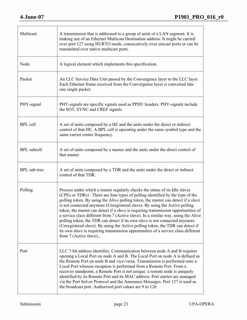
Multicast A transmission that is addressed to a group of units of a LAN segment. It is making use of an Ethernet Multicast Destination address. It might be carried over port 127 using HURTO mode, consecutively over unicast ports or can be transmitted over native multicast ports.
Node A logical element which implements this specification.
Packet An LLC Service Data Unit passed by the Convergence layer to the LLC layer. Each Ethernet frame received from the Convergence layer is converted into one single packet.
PHY-signal PHY-signals are specific signals used as PPDU headers. PHY-signals include the SOT, SYNC and CREF signals.
BPL cell A set of units composed by a HE and the units under the direct or indirect control of that HE. A BPL cell is operating under the same symbol type and the same carrier center frequency.
BPL subcell A set of units composed by a master and the units under the direct control of that master
BPL sub-tree A set of units composed by a TDR and the units under the direct or indirect control of that TDR.
Polling Process under which a master regularly checks the status of its Idle slaves (CPEs or TDRs) . There are four types of polling identified by the type of the polling token. By using the Alive polling token, the master can detect if a slave is not connected anymore (Unregistered slave). By using the Active polling token, the master can detect if a slave is requiring transmission opportunities of a service class different from 7 (Active slave). In a similar way, using the Alive polling token, the TDR can detect if its own slave is not connected anymore (Unregistered slave). By using the Active polling token, the TDR can detect if its own slave is requiring transmission opportunities of a service class different from 7 (Active slave).,
Port LLC 7-bit address identifier. Communication between node A and B requires opening a Local Port on node A and B. The Local Port on node A is defined as the Remote Port on node B and vice-versa. Transmission is performed onto a Local Port whereas reception is performed from a Remote Port. From a receiver standpoint, a Remote Port is not unique: a remote node is uniquely identified by its Remote Port and its MAC address. Port entries are managed via the Port Solver Protocol and the Announce Messages. Port 127 is used as the broadcast port. Authorized port values are 9 to 126.

4-June-07 P1901_PRO_016_r0
Submission page 24 UPA-OPERA
Port Solver Table Addressing table used by the LLC layer. It contains entries with the association between MAC addresses of the distant nodes and ports. The entries are complete when both the local and first remote ports are assigned or incomplete when only the local port is assigned and the remote port is set to 0xFF. A second remote port is also available to perform native multicast transmissions
QC (QoS Controller)
QC is the node that distributes the access to the channel among all the nodes present in a PLC cell, sharing the same NID or not. It can be defined as the master of the PLC cell. Any node can become a QC. The QC cannot be fixed by the user and it is decided by the nodes. The QC shall be the FMN of the high priority data traffic of the BPL cell.
Registered slave A slave whose access to the network has been authorized via the Access Protocol. A Registered slave can be Active or Alive.
REP Refers to either TDR or FDR
Slave A node for which transmission opportunities are controlled by its master. These transmission opportunities are specified as Validity Periods carried in some specific tokens delivered by the master. Slaves which are part of a TDR can delegate these transmission opportunities to their associated internal master (see TDR definition).
SOT A specific PHY-signal which starts all PPDUs. It is also used as a positive acknowledgement of a polling request.
Spatial reuse A feature which enables simultaneous node transmissions within non interfering BPL sub-trees of a single BPL cell. This feature relies on the non-returnable token and the Cluster Discovery Protocol
OFDM Symbol Transmitted signal for that portion of time when the modulating amplitude and phase state is held constant on each of the equally-spaced subcarriers in the signal.
Symbol type One from three different kinds of OFDM symbol, according to its duration.
TDR A BPL unit made of both an internal master part and a slave part which never operate at the same time. A TDR behaves either as a master or as a slave at different time periods. Contrarily to a HE, the master part of a TDR is not a permanent master which has permanent control of its transmission opportunities. The right to communicate of the master part of a TDR depends on the Validity Period assigned to its associated slave part.

4-June-07 P1901_PRO_016_r0
Submission page 25 UPA-OPERA
Tonemap Table that contains the amount of bits that shall be transmitted by each subcarrier.
Token The token is the MAC delimiter which terminates a regular MPDU. There are ten types of tokens: data and distributor token are used to propose transmission opportunities to one or more distant node, access/access reply tokens are used to discover Unregistered slaves, polling and TDR token are used for the slave and TDR states polling respectively, non-returnable token is used for allocating simultaneous transmission opportunities to several slaves (spatial reuse), silence token is used for sending a regular MPDU and keeping control of the medium after the transmission of this MPDU, CSMA token allow the priorized contention for the following transmission to every node that demodulate it, and clock token allow the synchronization in time of every node in the BPL cell.
Unicast A transmission that is addressed to a unique recipient.
Unregistered slave An Unregistered slave is not managed by any master. A master can detect such slaves via the exchange of an access frame and an access reply frame.
Visibility From a node to another node, when the first node is able to demodulate the token announce sent by the second node.
Word A data unit of 32-bits
1.6 ABBREVIATIONS AND ACRONYMS
4D Four Dimensional
AAA Authorization – Authentication – Accounting
ABLP Adaptive Bit-Loading Protocol
ABR Available Bit Rate
ACK ACKnowledge

4-June-07 P1901_PRO_016_r0
Submission page 26 UPA-OPERA
AFE Analogue Front End
AGC Automatic Gain Control
ANSI American National Standards Institute
APL Aggregated Payload Length
ARQ Automatic Repeat Request
ARP Address Resolution Protocol
ATM Asynchronous Transfer Mode
BE Best Effort
BER Bit Error Rate
BH Burst Header
BNDA Border Node Designation Acknowledge
BNDP Border Node Designation Protocol
BPC Bits Per subCarrier
BPDU Bridge Protocol Data Unit
BPS Bits Per Symbol
CAC Connection Admission Control
CBR Constant Bit Rate
CCITT Comité Consultatif International Téléphonique et Télégraphique

4-June-07 P1901_PRO_016_r0
Submission page 27 UPA-OPERA
CDP Cluster Discovery Protocol
CLPDU Convergence Layer Protocol Data Unit
CP Cyclic Prefix
CPE Customer Premises Equipment
CRC Cyclic Redundancy Check
CSM Class of Service Monitor
CTS Clear To Send
CW CodeWord
DAC Digital to Analogue Converter
DES Data Encryption Standard
DS DownStream
DSP Digital Signal Processing
EMC Electromagnetic Compatibility
FCMP Fair Congestion Management Policy
FEC Forward Error Correction
FIPS Federal Information Processing Standards
FFT Fast Fourier Transform
FTP File Transfer Protocol
4-June-07 P1901_PRO_016_r0
Submission page 28 UPA-OPERA
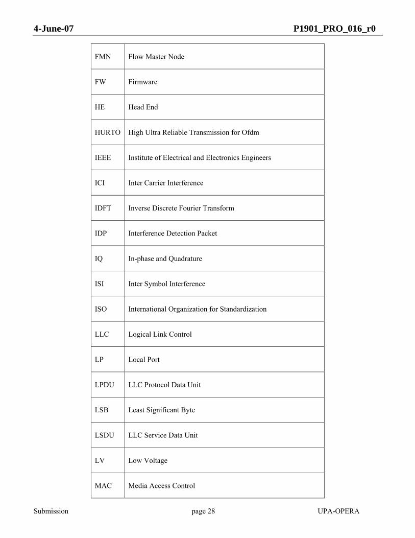
FMN Flow Master Node
FW Firmware
HE Head End
HURTO High Ultra Reliable Transmission for Ofdm
IEEE Institute of Electrical and Electronics Engineers
ICI Inter Carrier Interference
IDFT Inverse Discrete Fourier Transform
IDP Interference Detection Packet
IQ In-phase and Quadrature
ISI Inter Symbol Interference
ISO International Organization for Standardization
LLC Logical Link Control
LP Local Port
LPDU LLC Protocol Data Unit
LSB Least Significant Byte
LSDU LLC Service Data Unit
LV Low Voltage
MAC Media Access Control

4-June-07 P1901_PRO_016_r0
Submission page 29 UPA-OPERA
MIC Message Integrity Check
MID Master Identification
MPDU MAC Protocol Data Unit
MSB Most Significant Byte
MSDU MAC Service Data Unit
MTU Maximum Transfer Unit
MV Medium Voltage
OFDM Orthogonal Frequency Division Multiplexing
OPERA Open PLC European Research Alliance
CCP Communication Control Protocol
OSI Open Systems Interconnection
OUI Organizationally Unique Identifier
OVLAN Optimized VLAN
PAP Packet ACK Protocol
PAR Peak to Average Ratio
PBPS Physical Bits Per Symbol
PCMP Priority Congestion Management Policy
PDU Protocol Data Unit

4-June-07 P1901_PRO_016_r0
Submission page 30 UPA-OPERA
PHY PHYsical layer
BPL BPL Communications
PN Pseudo Noise
PPDU Physical Protocol Data Unit
PSD Power Spectral Density
PST Port Solver Table
QC QoS Controller
QoS Quality of Service
REP Repeater
RP Remote Port
RS Reed Solomon
RTS Request To Send
RX Reception
SNAP SubNetwork Access Protocol
SNR Signal to Noise Ratio
SLA Service Level Agreement
SOT Start of Transmission
STP Spanning Tree Protocol

4-June-07 P1901_PRO_016_r0
Submission page 31 UPA-OPERA
TA Token Announce
TCM Trellis Coded Modulation
TCP Transfer Control Protocol
TDD Time Division Duplexing
TDMA Time Division Multiple Access
TDR Time Division Repeater
TO TimeOut
TX Transmission
UDP User Datagram Protocol
UPA Universal BPL Association
US UpStream
VBR Variable Bit Rate
VLAN Virtual Local Area Network
VoIP Voice over IP
2 GENERAL DESCRIPTION
An access BPL network consists of a number of user terminals (CPEs) that transmit/receive traffic in a shared medium to/from a centralized station (HE). If the signal is too attenuated to reach all CPEs from the same HE, repeaters (REP) can be inserted in the network in order to retransmit the signal and thus increase the coverage. Repeaters can be either TDR or FDR. From this description, the type of topologies to be found in BPL access

4-June-07 P1901_PRO_016_r0
Submission page 32 UPA-OPERA
networks are tree-like topologies, like the one depicted in Figure 1, where a central node, called a HE, concentrates all of the upstream and downstream traffic, although other topologies, as the ring shape topologies, are also common. All kinds of structures in Medium Voltage (MV) and Low Voltage (LV) can be reduced to a HE plus Repeaters structure.
HE
REP
CPE CPE
REP
CPE CPE
HE
REP
REP
CPE
REP
CPE
Figure 1 Typical Access Scenario
2.1 GENERAL DESCRIPTION OF THE ARCHITECTURE
2.2 NODE DESCRIPTION
A BPL network can be made either of:
• one BPL cell,
• several BPL cells if they are interconnected via Frequency Division repeaters (FDR). FDR are made of a combination of one HE and one CPE or TDR operating in different modes.
In an access BPL network, there is usually one HE, placed in the MV/LV substation, that concentrates the upstream and downstream traffic from/to all the CPEs of all the connected BPL cells.
4-June-07 P1901_PRO_016_r0
Submission page 33 UPA-OPERA
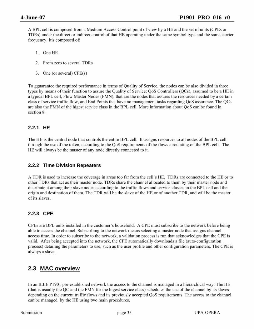
A BPL cell is composed from a Medium Access Control point of view by a HE and the set of units (CPEs or TDRs) under the direct or indirect control of that HE operating under the same symbol type and the same carrier frequency. Itis composed of:
1. One HE
2. From zero to several TDRs
3. One (or several) CPE(s)
To gguarantee the required performance in terms of Quality of Service, the nodes can be also divided in three types by means of their function to assure the Quality of Service: QoS Controllers (QCs), assumed to be a HE in a typical BPL cell, Flow Master Nodes (FMN), that are the nodes that assures the resources needed by a certain class of service traffic flow, and End Points that have no management tasks regarding QoS assurance. The QCs are also the FMN of the higest service class in the BPL cell. More information about QoS can be found in section 8.
2.2.1 HE
The HE is the central node that controls the entire BPL cell. It assigns resources to all nodes of the BPL cell through the use of the token, according to the QoS requirements of the flows circulating on the BPL cell. The HE will always be the master of any node directly connected to it.
2.2.2 Time Division Repeaters
A TDR is used to increase the coverage in areas too far from the cell’s HE. TDRs are connected to the HE or to other TDRs that act as their master node. TDRs share the channel allocated to them by their master node and distribute it among their slave nodes according to the traffic flows and service classes in the BPL cell and the origin and destination of them. The TDR will be the slave of the HE or of another TDR, and will be the master of its slaves.
2.2.3 CPE
CPEs are BPL units installed in the customer’s household. A CPE must subscribe to the network before being able to access the channel. Subscribing to the network means selecting a master node that assigns channel access time. In order to subscribe to the network, a validation process is run that acknowledges that the CPE is valid. After being accepted into the network, the CPE automatically downloads a file (auto-configuration process) detailing the parameters to use, such as the user profile and other configuration parameters. The CPE is always a slave.
2.3 MAC overview
In an IEEE P1901 pre-established network the access to the channel is managed in a hierarchical way. The HE (that is usually the QC and the FMN for the higest service class) schedules the use of the channel by its slaves depending on the current traffic flows and its previously accepted QoS requirements. The access to the channel can be managed by the HE using two main procedures.
4-June-07 P1901_PRO_016_r0
Submission page 34 UPA-OPERA
1. Sending indidually to each of the slaves a data or distributor frame, containg data from the HE to the slaves and finished by a token that contains the next slave or list of slaves that shall use the channel when the first transmission is finished in a predetermined order. The amount of channel time assigned by the HE and can be fixed for a timing interval or not. In the first case the channel allocation can be synchronous with the mains or not. In the second case if a node does not use the entire assigned time, the right to transmit is immeadiately given to the following node in the list or returned to the HE.:
2. Sending a CSMA token, that opens a priorized contention among the nodes that receive it. The winner of the contention shall obtain the right to transmit for the given amount of time, and then, the right to transmit is returned to the HE.
By means of the first procedure, a timing interval can be programmed where different slaves can allocate their transmissions.
2.4 QoS overview
IEEE P1901 provides various mechanisms to assure the QoS of the traffic flows in the BPL cell. Traffic flows are session oriented and tagged with certain service class that implies certain requirements in terms of latency and bandwith, jointly with a requirement in terms of level of assurance of the reserved resources.
A slave requiring to transmit certain type of traffic shall first classify it in one of the eight available service classes, each one with a preprogrammed latency, bandwidth and level of assurance of the required resources, that can be Variable Bit Rate (VBR), Constant Bit Rate (CBR), Available Bit Rate (ABR) or Best Effort. The mapping from Service Classes to the Bandwith, Latency and Type of Traffic is common and known by all nodes in the BPL cell.
Then, by means of the Connection Admission Control (CAC) protocol, the requirements to transmit the traffic flow are solicited to the Flow Master Node of this service class, and can be accepted and a session ID shall be assigned to it, or rejected.
In the case where the maximum capacity of the channel is reached, several congestion policies can be applied by the QC and FMNs to admit, reject or drop current sessions in the BPL cell (See 8.3).
2.5 Security overview
IEEE P1901 specification provides a state-of-art security mechanism including CTR 128 bits AES encryption with individual key for each CLPDU or fragment of CLPDU, integrity mechanisms by means of CBC 128 bits AES also performed individually for each CLPDU or fragment CLPDU, integrity protection of MAC addess, RADIUS and 802.1X based key distribution and AAA protocol, etc.
Recommendations from 802.11i standard have been specially taken into account to design the security specification of IEEE P1901. More details are disclosed in section 10.

4-June-07 P1901_PRO_016_r0
Submission page 35 UPA-OPERA
2.6 NETWORK REFERENCE MODEL
This specification defines PHY, MAC, LLC and Convergence Layer functionality as well as minimal bridging
requirements to be supported by all compliant implementations. It also defines layer management functions.
Finally, it also contains specifications for Security and Configuration, including MIBs and autoconfiguration
issues.
Figure 2 System Reference Model
4-June-07 P1901_PRO_016_r0
Submission page 36 UPA-OPERA
This document specifies Packet Management, LLC, MAC and PHY behaviour. End-to-end services are provided by protocol layers not specified in this document.
At an application level the system appears as a black box between information packet interfaces and the BPL.
The Bridging function is mandatory and described in section 7. From a bridging standpoint, the layer management block is connected to the bridging function via a management port. The Convergence Layer is seen as a set of BPL ports.
The Convergence layer performs the Ethernet Frame to Packet conversion. This function performs the conversion between Ethernet II/802.3 frames (802.1 p/q tagged or untagged) and 32-bit aligned packets. On the transmission path, the converter also sets the priority and the OVLAN tag, if needed. The Broadcast/Multicast handling is also done at this level.
The LLC layer provides peer convergence layers with the ability to exchange LLC service data units (LSDUs=packets). Given a maximum size constraint on the LPDU payload provided by the layer management, the LLC segments and/or groups packets into LPDU payloads (burst payloads) to be transferred over the same transmission port. When several packets are present within a burst payload, inter-packets headers are appended. In relation with the layer management, the LLC also deals with encryption/decryption of burst payloads. The LLC will append the burst header to a burst payload.
The MAC layer provides peer LLC layers with the ability to exchange MAC service data units (MSDUs=LPDUs=burst). On the transmission path, the MAC layer performs the grouping of bursts=MSDU into an MPDU. The MAC layer also provides the layer management with the ability to generate specific MPDUs=frames for performing background tasks: silence management, channel estimation, node status polling and node discovery. The MAC layer handles 7 types of frames (data, silence, channel estimation, polling, access, access reply and non-returnable data). All these frames start with a token announce delimiter. Except for the channel estimation frame, all the other frames are terminated with a token delimiter which content depends on the type of the frame.
The PHY layer performs the OFDM modulation and the digital signal processing (DSP) needed to transmit the MPDU over the BPL channel. It also adds the FEC redundancy.
3 PHY
This section specifies the Physical Layer Entity for an Orthogonal Frequency Division Multiplexing (OFDM) system. OFDM has been chosen as the modulation technique because of its inherent adaptability in the presence of frequency selective channels, its resilience to jammer signals, its robustness to impulsive noise and its capacity of achieving high spectral efficiencies.

4-June-07 P1901_PRO_016_r0
Submission page 37 UPA-OPERA
3.1 OVERVIEW
The diagram in Figure 3 shows an example PHY layer of a transmitter.
On the transmitter side, the PHY layer receives its inputs from the Media Access Control Layer. Two separate bit streams are shown because of the different encoding for data and control information. The delimiters shall be interleaved by the Control Interleaving block and mapped by the HURTO Mapping block; while the data stream shall be mapped using the HURTO Mapping block or the Adaptive Mapping block, depending on the reliability level required for the transmission. The outputs of both Mapping blocks lead into the Scrambler, which is followed by 4D-TCM (Four Dimensional Trellis Coded Modulation) encoding. The next step is the OFDM Modulation, which is composed of the Subcarrier Modulator, the IDFT (Inverse Discrete Fourier Transform), the Cyclic Prefix generator and the symbol windowing operation structure. The resulting digital signal is converted to an analog signal by means of a DAC and IQ modulated, before passing to the amplifying and filtering stages.
Data payload
Delimiters
IDFT Cyclic Prefix 4D TCM
SubcarrierModulator
HURTOMapping
Scrambler Window
DAC
AmplifiersFilters
Data Reed-Solomon
Encoder Adaptive Mapping
Control Reed-Solomon
Encoder
Power Line
Control InterleavingCRC
IQ mod
Figure 3 Transmission PHY layer
3.2 PHY LAYER FRAME
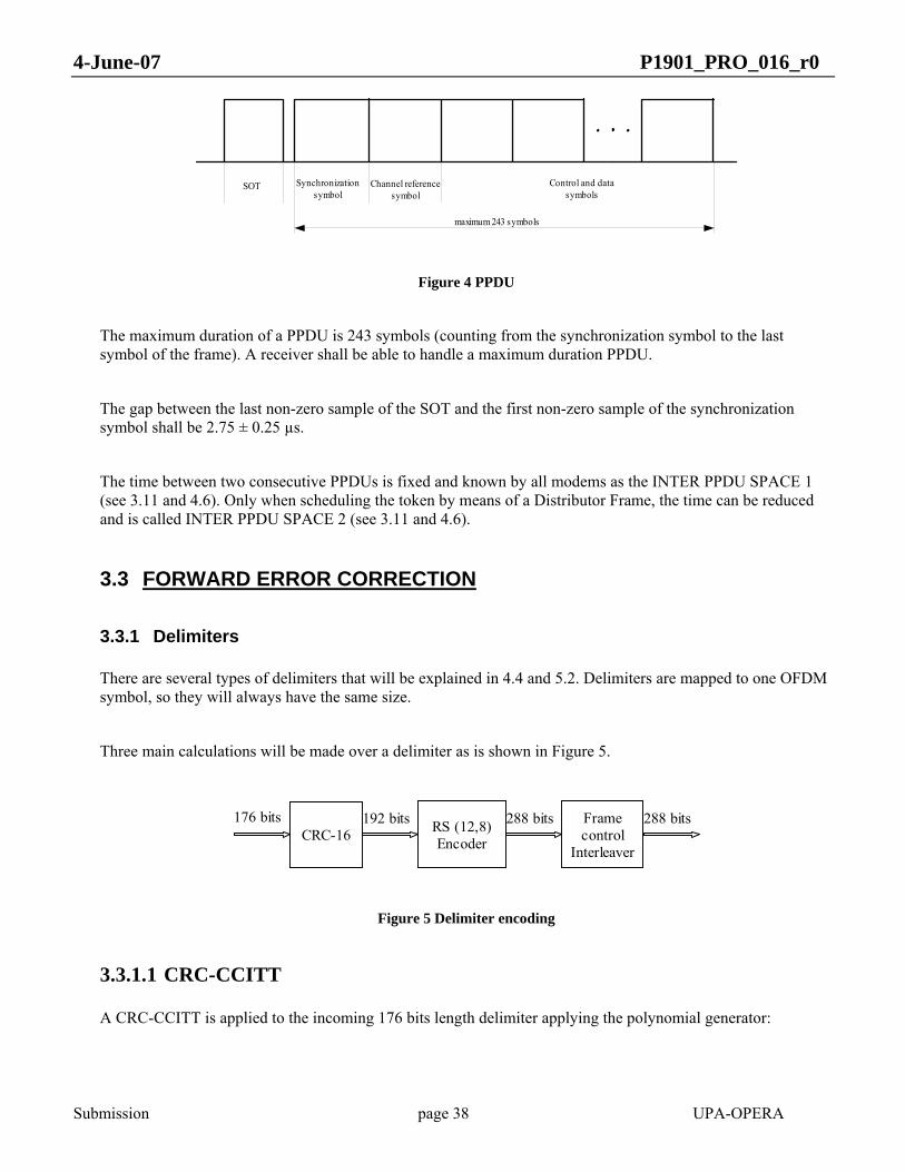
Figure 4 shows the symbols that are transmitted in a PPDU.
4-June-07 P1901_PRO_016_r0
Submission page 38 UPA-OPERA
SOT Synchronizationsymbol
Channel referencesymbol
Control and datasymbols
maximum 243 symbols
Figure 4 PPDU
The maximum duration of a PPDU is 243 symbols (counting from the synchronization symbol to the last symbol of the frame). A receiver shall be able to handle a maximum duration PPDU.
The gap between the last non-zero sample of the SOT and the first non-zero sample of the synchronization symbol shall be 2.75 ± 0.25 µs.
The time between two consecutive PPDUs is fixed and known by all modems as the INTER PPDU SPACE 1 (see 3.11 and 4.6). Only when scheduling the token by means of a Distributor Frame, the time can be reduced and is called INTER PPDU SPACE 2 (see 3.11 and 4.6).
3.3 FORWARD ERROR CORRECTION
3.3.1 Delimiters
There are several types of delimiters that will be explained in 4.4 and 5.2. Delimiters are mapped to one OFDM symbol, so they will always have the same size.
Three main calculations will be made over a delimiter as is shown in Figure 5.
CRC-16 RS (12,8)Encoder
Framecontrol
Interleaver
176 bits 192 bits 288 bits 288 bits
Figure 5 Delimiter encoding
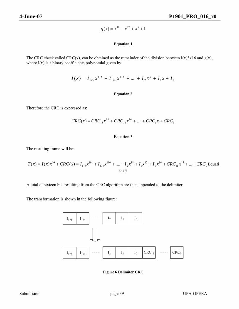
3.3.1.1 CRC-CCITT
A CRC-CCITT is applied to the incoming 176 bits length delimiter applying the polynomial generator:
4-June-07 P1901_PRO_016_r0
Submission page 39 UPA-OPERA
1)( 51216 +++= xxxxg
Equation 1
The CRC check called CRC(x), can be obtained as the remainder of the division between I(x)*x16 and g(x), where I(x) is a binary coefficients polynomial given by:
012
2174
174175
175 ....)( IxIxIxIxIxI +++++=
Equation 2
Therefore the CRC is expressed as:
0114
1415
15 ....)( CRCxCRCxCRCxCRCxCRC ++++=
Equation 3
The resulting frame will be:
015
1516
017
118
2190
174191
17516 .......)()()( CRCxCRCxIxIxIxIxIxCRCxxIxT ++++++++=+= Equati
on 4
A total of sixteen bits resulting from the CRC algorithm are then appended to the delimiter.
The transformation is shown in the following figure:
I175 I174 I2 I1 I0
I175 I174 I2 I1 I0 CRC15 CRC0
Figure 6 Delimiter CRC
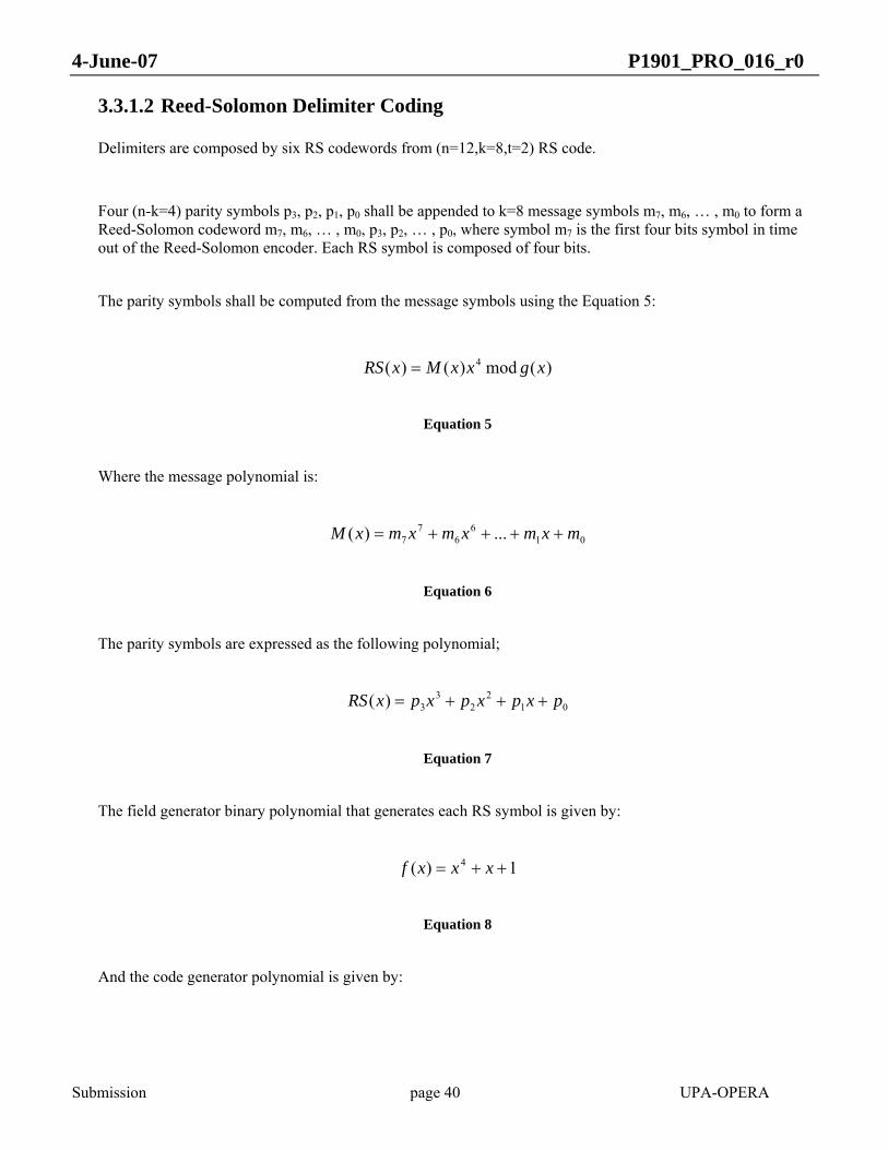
4-June-07 P1901_PRO_016_r0
Submission page 40 UPA-OPERA
3.3.1.2 Reed-Solomon Delimiter Coding
Delimiters are composed by six RS codewords from (n=12,k=8,t=2) RS code.
Four (n-k=4) parity symbols p3, p2, p1, p0 shall be appended to k=8 message symbols m7, m6, … , m0 to form a Reed-Solomon codeword m7, m6, … , m0, p3, p2, … , p0, where symbol m7 is the first four bits symbol in time out of the Reed-Solomon encoder. Each RS symbol is composed of four bits.
The parity symbols shall be computed from the message symbols using the Equation 5:
)(mod)()( 4 xgxxMxRS =
Equation 5
Where the message polynomial is:
016
67
7 ...)( mxmxmxmxM ++++=
Equation 6
The parity symbols are expressed as the following polynomial;
012
23
3)( pxpxpxpxRS +++=
Equation 7
The field generator binary polynomial that generates each RS symbol is given by:
1)( 4 ++= xxxf
Equation 8
And the code generator polynomial is given by:

4-June-07 P1901_PRO_016_r0
Submission page 41 UPA-OPERA
))()()(()( 4321 αααα −−−−= xxxxxg
Equation 9
The RS binary symbol representation for delimiters of α0 is 0b0001, where the left most bit of this RS symbol is the most significant bit (MSB). This way, the binary representation of each of the redundancy symbols generated on the Galois field GF(24) denoted as p3, p2, p1, p0 will be represented as RSX15, RSX14, RSX13, and RSX12 for the symbol p3, RSX11, RSX10, RSX9, and RSX8 for the symbol p2, RSX7, RSX6, RSX5, and RSX4 for the symbol p1 and RSX3, RSX2, RSX1, and RSX0 for the symbol p0, where X denotes the RS codeword number.
The following figure shows the final binary level representation of the delimiter:
I175 I174 I144 RS115 RS10
I143 I112 RS215 RS20I142
CRC0 RS615 RS60I15 I14
Figure 7 Reed Solomon bit format
The first bit to be transmitted is the leftmost of the first codeword (I175), followed by the rest of the bits of the RS codeword. Then, the second codeword, and so on. This is illustrated in
015011101430174175 6...5.......2...1... RSIRSIRSIRSII
Figure 8 Reed Solomon bit order
3.3.1.3 Delimiter Interleaving
After RS encoding, the six resulting RS codewords shall be interleaved with interleaving depth of six RS codewords and 4 bits granularity, in such a way that the first four bits of each RS codeword shall be sent first to the interleaver, then, the second 4 bits of each of the six RS codewords and so on. We can group the bits in nibbles for clarity:
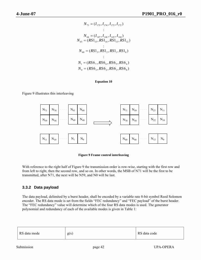
4-June-07 P1901_PRO_016_r0
Submission page 42 UPA-OPERA
)6,6,6,6()6,6,6,6(
:)1,1,1,1(
:)1,1,1,1(
),,,(:
),,,(
01230
45671
012360
1213141563
14414514614764
17217317417571
RSRSRSRSNRSRSRSRSN
RSRSRSRSN
RSRSRSRSNIIIIN
IIIIN
==
=
==
=
Equation 10
Figure 9 illustrates this interleaving
N71 N70 N61 N60
N59 N58 N49 N48
N11 N10 N1 N0
N71 N59 N23 N11
N70 N58 N22 N10
N60 N48 N12 N0
Figure 9 Frame control interleaving
With reference to the right half of Figure 9 the transmission order is row-wise, starting with the first row and from left to right, then the second row, and so on. In other words, the MSB of N71 will be the first to be transmitted, after N71, the next will be N59, and N0 will be last.
3.3.2 Data payload
The data payload, delimited by a burst header, shall be encoded by a variable rate 8-bit symbol Reed Solomon encoder. The RS data mode is set from the fields “FEC redundancy” and “FEC payload” of the burst header. The “FEC redundancy” value will determine which of the four RS data modes is used. The generator polynomial and redundancy of each of the available modes is given in Table 1:
RS data mode g(x) RS data code

4-June-07 P1901_PRO_016_r0
Submission page 43 UPA-OPERA
0 ))...()()(()( 832 αααα −−−−= xxxxxg (k0+8,k0,t=4)
1 ))...()()(()( 1232 αααα −−−−= xxxxxg (k1+12, k1,t=6)
2 ))...()()(()( 1632 αααα −−−−= xxxxxg (k2+16, k2,t=8)
3 ))...()()(()( 2032 αααα −−−−= xxxxxg (k3+20, k3,t=10)
Table 1 RS data polynomials
The “FEC payload” field in each burst header contains the number of 32-bit words that will be coded per RS codeword, and therefore determines the amount of payload bytes per codeword (ki).
Maximum and minimum value for this field is given depending on the mode in Table 2:
Min payload in words RS data mode
Redundancy words
Max payload in words
HURTO Adaptive
0 2 61 2 34
1 3 60 3 33
2 4 59 4 32
3 5 58 5 31
Table 2 RS data payload
Each data payload shall be coded following a different RS coding scheme that will be configured in each Burst header. The selected coding scheme is a shortened Reed-Solomon code that can be processed as a systematic RS(255, 255-2*ti,ti) by adding 255-(ki+2ti) bytes set to zero before the information bits. After the RS coding procedure these null bytes shall be discarded, leading to RS codewords of n = ki+2t bytes

4-June-07 P1901_PRO_016_r0
Submission page 44 UPA-OPERA
When the data payload length is not an integer number of Reed-Solomon codewords, the last Reed Solomon codeword will have a special coding given by the formula:
[ ] ttkAPLk ilastcw 2)*2mod()*4( −+=
Equation 11
Where APL is the data payload length in number of 32-bit words including RS coding parity bits.
For the last codeword, no minimum value in k is applied.
The incoming data payload shall be grouped in L groups of ki bytes, where ki has been taken from the “FEC payload” field in burst header, and a last group of klastcw bytes, calculated from Equation 11, as can be seen in the following figure:
IL*ki+klastcw-1 IL*ki+klastcw-2 I(L-1)*ki+klastcw RS12*t-1 RS10
I(L-1)*ki+klastcw-1 I(L-1)*ki+klastcw-2 I(L-2)*ki+klastcw RS22*t-1 RS20
Iklastcw-1 Iklastcw-2 I0 RS(L+1)2*t-1 RS(L+1)0
Iki+klastcw-1 Iki+klastcw-2 Iklastcw RSL2*t-1 RSL0
L Blocks
ki bytes
klastcw
bytes
2*t bytes
2*t b
ytes
Figure 10 Reed Solomon byte grouping
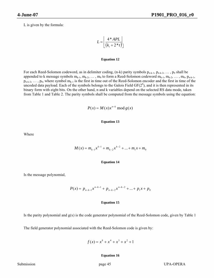
4-June-07 P1901_PRO_016_r0
Submission page 45 UPA-OPERA
L is given by the formula:
( )⎥⎦⎥
⎢⎣
⎢+
=tk
APLLi *2*4
Equation 12
For each Reed-Solomon codeword, as in delimiter coding, (n-k) parity symbols pn-k-1, pn-k-2, … , p0 shall be appended to k message symbols mk-1, mk-2, … , m0 to form a Reed-Solomon codeword mk-1, mk-2, … , m0, pn-k-1, pn-k-2, … , p0, where symbol mk-1 is the first in time out of the Reed-Solomon encoder and the first in time of the uncoded data payload. Each of the symbols belongs to the Galois Field GF(28), and it is then represented in its binary form with eight bits. On the other hand, n and k variables depend on the selected RS data mode, taken from Table 1 and Table 2. The parity symbols shall be computed from the message symbols using the equation:
)(mod)()( xgxxMxP kn−=
Equation 13
Where
012
21
1 ...)( mxmxmxmxM kk
kk ++++= −
−−
−
Equation 14
Is the message polynomial,
012
21
1 ...)( pxpxpxpxP knkn
knkn ++++= −−
−−−−
−−
Equation 15
Is the parity polynomial and g(x) is the code generator polynomial of the Reed-Solomon code, given by Table 1
The field generator polynomial associated with the Reed-Solomon code is given by:
1)( 2348 ++++= xxxxxf
Equation 16
4-June-07 P1901_PRO_016_r0
Submission page 46 UPA-OPERA
The binary representation of α0 is 0b00000001, where the left most bit of this RS symbol is the most significant bit (MSB).
3.4 MAPPING MODES
Once obtained a delimiter or a data payload, one from two different mapping procedures shall be used. The mapping mode is indicated with the field HURTO in the burst header (see section 5.2). HURTO mapping is fixed. Adaptive mapping will be done following a table (called bit-loading table) with information on how many coded bits will be allocated in each of the 1536 subcarriers in a symbol
3.4.1 HURTO mapping
HURTO mode shall be used in all delimiters and in the data payload if it is indicated in the HURTO field in the burst header.
First, groups of 288 consecutive bits are made. Each of these groups is replicated eight times, in order to obtain groups of 2304 bits. The bit allocation table will be set to 2 bits per subcarrier for all the 1536 subcarriers of an OFDM symbol, and each resulting 2304 bits groups shall complete an entire OFDM symbol. 4D-TCM encoding will be done, with a reset in convolutional encoder each 288 incoming bits.
In the data payload case with the HURTO bit set in the burst header, the last group will be completed with zeroes, if necessary.

4-June-07 P1901_PRO_016_r0
Submission page 47 UPA-OPERA
Controlframe orHURTO
dataframe
zerofilling ifneeded
288bits
length
288bits
length
288bits
length2304bitslength
Frame to encode by 4DTCMafter scrambling
Frame after block coding.MSB is up.
Number of groups will be onefor control frame and no zerofilling will be done. Transmission orderwill be up to down, MSB first.
Figure 11 HURTO mapping
3.4.2 Adaptive mapping
When the HURTO bit is unset in the burst header, the data payload will be mapped following the bit allocation table, which sets how many coded (after 4D-TCM) bits will be allocated in each subcarrier.
When adaptive mapping is used, there must be at least 24 subcarriers with 2 or more information bits.

4-June-07 P1901_PRO_016_r0
Submission page 48 UPA-OPERA
Normal
Data Frame
Transmission order will be top to bottom, msb first.
BPS Bits
Frame after block coding. msb is up.
Zero filling if needed
Figure 12 Adaptive mapping
BPS in the figure means the number of necessary data bits to fill an entire OFDM symbol with a certain bit-loading. A mathematical expression of this definition is shown in Equation 17. The last symbol shall be padded with zeros before scrambling, if necessary, until an integer number of symbols is used.
3.5 TRELLIS CODED MODULATION (4D-TCM)
Once obtained a delimiter or data payload that will fill a integer number of OFDM symbols, a 16 state 4-dimensional truncated trellis code is used for error correction. This code will be applied over groups of 1536 subcarriers and reset each OFDM symbol, except in HURTO mode, where the 4D-TCM encoder will be reset each 192 subcarriers out, or, in other words, each 288 bits in.
3.5.1 Bit Extraction
Data bits from both delimiters and data payload shall be extracted according to a bit-loading table bj, with j=0…1535, righter bits first, in groups of z bits. In the case of HURTO mapping bj= 2 ∀j ∈ [0..1535]. Due to the constellation expansion associated with coding and the 4-dimensional nature of the code, zi will be calculated from a given pair (x,y) of two consecutive bj, where bj is the number of coded bits that subcarrier j will transmit.
Due to the heavy impairments of the BPL channel, or regional regulations, some subcarriers can be set not to carry any information. This case is denoted with a bit loading bj = 0 for such subcarriers. When the two consecutive subcarriers x and y that form a symbol of the four dimensional code are set to zero, no bit extraction is performed, and the following pair of subcarriers is taken into account. On the other hand, when only one of the two subcarriers
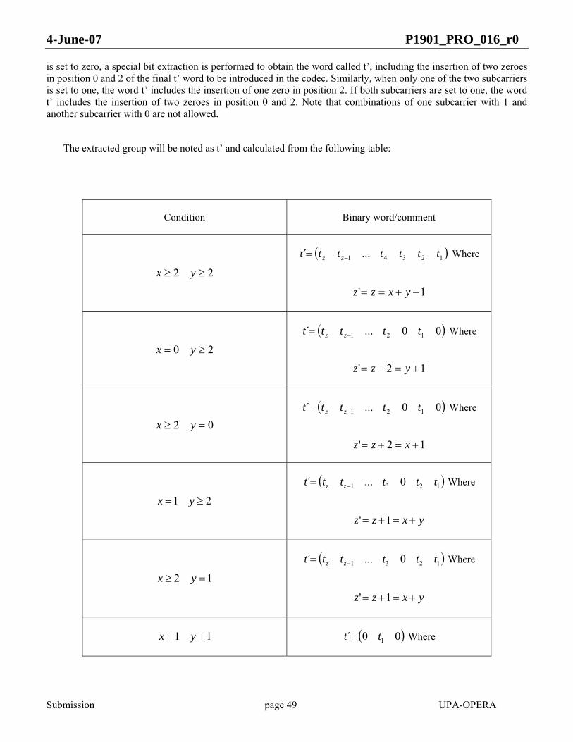
4-June-07 P1901_PRO_016_r0
Submission page 49 UPA-OPERA
is set to zero, a special bit extraction is performed to obtain the word called t’, including the insertion of two zeroes in position 0 and 2 of the final t’ word to be introduced in the codec. Similarly, when only one of the two subcarriers is set to one, the word t’ includes the insertion of one zero in position 2. If both subcarriers are set to one, the word t’ includes the insertion of two zeroes in position 0 and 2. Note that combinations of one subcarrier with 1 and another subcarrier with 0 are not allowed.
The extracted group will be noted as t’ and calculated from the following table:
Condition Binary word/comment
22 ≥≥ yx
( )12341 ...´ ttttttt zz −= Where
1' −+== yxzz
20 ≥= yx
( )00...´ 121 ttttt zz −= Where
12' +=+= yzz
02 =≥ yx
( )00...´ 121 ttttt zz −= Where
12' +=+= xzz
21 ≥= yx
( )1231 0...´ tttttt zz −= Where
yxzz +=+= 1'
12 =≥ yx
( )1231 0...´ tttttt zz −= Where
yxzz +=+= 1'
11 == yx ( )00´ 1tt = Where

4-June-07 P1901_PRO_016_r0
Submission page 50 UPA-OPERA
12' ++=+= yxzz
00 == yx Bit extraction not necessary, no message bits being sent
Table 3 Bit extraction
Since the maximum number of bits in a group will be 19, a 19 bits wide word called t´ will be formed from each two subcarriers, filling most significant bits with zeroes when z´ < 19. This word will be scrambled with a pseudorandom word generator.
The bits per symbol (BPS) is defined by:
SymbolizBPSi
i ∈∀= ∑
Equation 17
3.5.2 Scrambling
Each of the bits from the pseudorandom generator shall be generated with the same polynomial structure initialized with different seeds for each bit (where bit 0 is the least significant bit).
The pseudorandom sequence generator shall be the 10-bit PN generator with characteristic polynomial given by Equation 18.
( ) 1031 xxxf ++=
Equation 18
At the beginning of each symbol, the registers of the PN generators shall be set with the corresponding seeds given by Table 4
PN Seed

4-June-07 P1901_PRO_016_r0
Submission page 51 UPA-OPERA
0 0x2bf
1 0x3f0
2 0x3ff
3 0x28d
4 0x2d7
5 0x017
6 0x1e4
7 0x3d8
8 0x337
9 0x1f1
10 0x2a3
11 0x3f3
12 0x000
13 0x11f
14 0x329
15 0x177
16 0x331
17 0x119
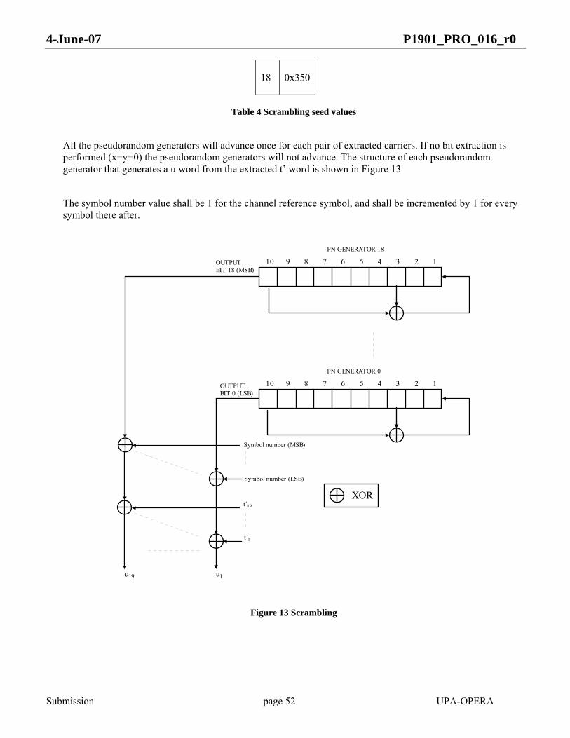
4-June-07 P1901_PRO_016_r0
Submission page 52 UPA-OPERA
18 0x350
Table 4 Scrambling seed values
All the pseudorandom generators will advance once for each pair of extracted carriers. If no bit extraction is performed (x=y=0) the pseudorandom generators will not advance. The structure of each pseudorandom generator that generates a u word from the extracted t’ word is shown in Figure 13
The symbol number value shall be 1 for the channel reference symbol, and shall be incremented by 1 for every symbol there after.
OUTPUTBIT 0 (LSB)
10 9 8 7 6 5 4 3 2 1
OUTPUTBIT 18 (MSB)
PN GENERATOR 0
u1u19
t´19
10 9 8 7 6 5 4 3 2 1
PN GENERATOR 18
t´1
XOR
Symbol number (LSB)
Symbol number (MSB)
Figure 13 Scrambling
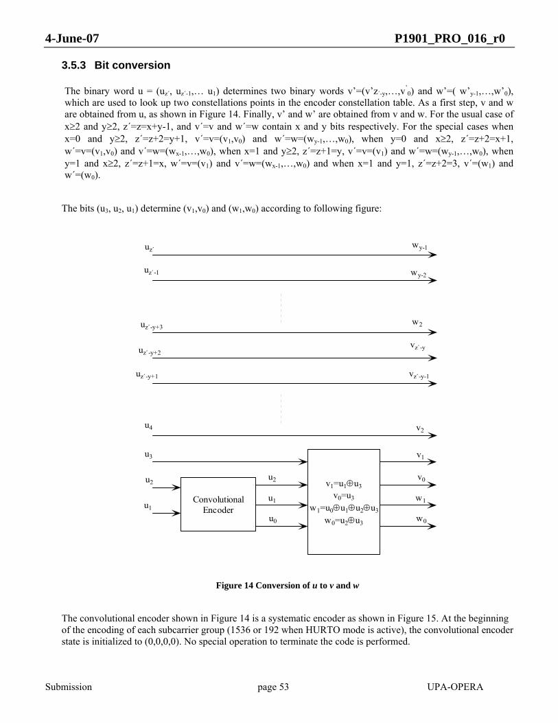
4-June-07 P1901_PRO_016_r0
Submission page 53 UPA-OPERA
3.5.3 Bit conversion
The binary word u = (uz´, uz´-1,… u1) determines two binary words v’=(v’z´-y,…,v’0) and w’=( w’y-1,…,w’0),
which are used to look up two constellations points in the encoder constellation table. As a first step, v and w are obtained from u, as shown in Figure 14. Finally, v’ and w’ are obtained from v and w. For the usual case of x≥2 and y≥2, z´=z=x+y-1, and v´=v and w´=w contain x and y bits respectively. For the special cases when x=0 and y≥2, z´=z+2=y+1, v´=v=(v1,v0) and w´=w=(wy-1,…,w0), when y=0 and x≥2, z´=z+2=x+1, w´=v=(v1,v0) and v´=w=(wx-1,…,w0), when x=1 and y≥2, z´=z+1=y, v´=v=(v1) and w´=w=(wy-1,…,w0), when y=1 and x≥2, z´=z+1=x, w´=v=(v1) and v´=w=(wx-1,…,w0) and when x=1 and y=1, z´=z+2=3, v´=(w1) and w´=(w0).
The bits (u3, u2, u1) determine (v1,v0) and (w1,w0) according to following figure:
ConvolutionalEncoder
v1=u1⊕u3v0=u3
w1=u0⊕u1⊕u2⊕u3
w0=u2⊕u3
uz´
uz´-1
uz´-y+3
uz´-y+2
uz´-y+1
u4
u3
u2
u1
u2
u1
u0
wy-1
wy-2
w2
vz´-y
vz´-y-1
v2
v1
v0
w0
w1
Figure 14 Conversion of u to v and w
The convolutional encoder shown in Figure 14 is a systematic encoder as shown in Figure 15. At the beginning of the encoding of each subcarrier group (1536 or 192 when HURTO mode is active), the convolutional encoder state is initialized to (0,0,0,0). No special operation to terminate the code is performed.

4-June-07 P1901_PRO_016_r0
Submission page 54 UPA-OPERA
Delay Delay DelayDelay
S0S1S2 S3
u1
u2
u0
u2
u1
Figure 15 Convolutional encoder
The remaining bits of v and w are obtained from the less significant and more significant parts of (uz´, uz´-1,…, u4), respectively. When x≥2 and y≥2, v´=v=(uz´-y+2, uz´-y+1,..., u4,v1,v0) and w´=w=(uz´, uz´-1,…, uz´-y+3,w1,w0). When x=0 or y=0 (but not both), v= (v1, v0), and it will be assigned to the zero loading subcarrier (v´ when only x=0 but not y and w´ when y=0 but not x). w will have y bits in the first case and x bits in the second, and will be assigned to the non zero loading subcarrier.
When x=1 or y=1 (but not both), v1 will be assigned to the 1 loading subcarrier (v´ when only x=1 but not y and w´ when y=1 but not x), v0 is dropped. w will have y bits in the first case and x bits in the second, and will be assigned to the non zero loading subcarrier.
When x=1 and y=1, v´=(w1) and w’=(w0)
The binary word v´ is input first to the constellation encoder, and the binary word w´ last.
3.5.4 Constellation encoder
Each of the two resulting binary words after 4D-TCM process, called v’ and w’, represent an amplitude ak and an increment to previous phase, called Δbk that will perform a new constellation point to be transmitted in one subcarrier. The first word to be processed and transmitted will be v’ and then w’. Since the mapping process to amplitude and phase increment will be the same for v’ and w’, we consider the following description based in a binary word called I that can be v’ or w’ indistinctly.
In the following table, mapping for each bit-loading and the pair (ak, Δbk) and its relationship with the binary word I is shown.
Bit-loading ak Δbk
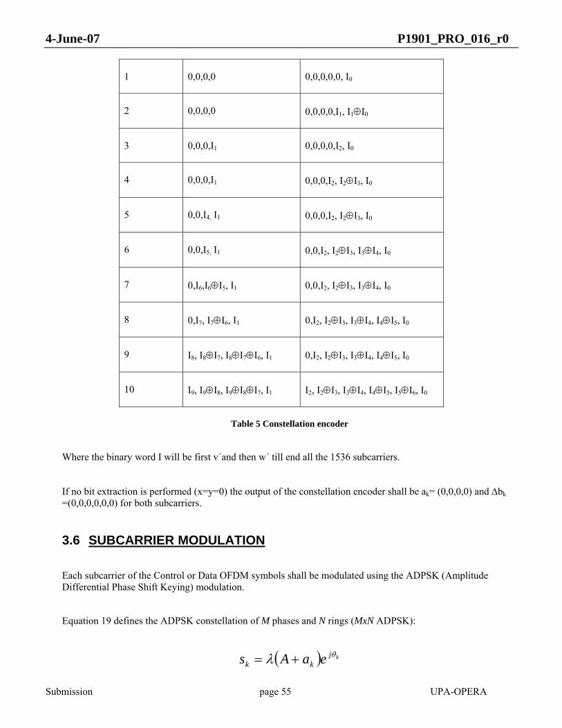
4-June-07 P1901_PRO_016_r0
Submission page 55 UPA-OPERA
1 0,0,0,0 0,0,0,0,0, I0
2 0,0,0,0 0,0,0,0,I1, I1⊕I0
3 0,0,0,I1 0,0,0,0,I2, I0
4 0,0,0,I1 0,0,0,I2, I2⊕I3, I0
5 0,0,I4, I1 0,0,0,I2, I2⊕I3, I0
6 0,0,I5, I1 0,0,I2, I2⊕I3, I3⊕I4, I0
7 0,I6,I6⊕I5, I1 0,0,I2, I2⊕I3, I3⊕I4, I0
8 0,I7, I7⊕I6, I1 0,I2, I2⊕I3, I3⊕I4, I4⊕I5, I0
9 I8, I8⊕I7, I8⊕I7⊕I6, I1 0,I2, I2⊕I3, I3⊕I4, I4⊕I5, I0
10 I9, I9⊕I8, I9⊕I8⊕I7, I1 I2, I2⊕I3, I3⊕I4, I4⊕I5, I5⊕I6, I0
Table 5 Constellation encoder
Where the binary word I will be first v´and then w´ till end all the 1536 subcarriers.
If no bit extraction is performed (x=y=0) the output of the constellation encoder shall be ak= (0,0,0,0) and Δbk =(0,0,0,0,0,0) for both subcarriers.
3.6 SUBCARRIER MODULATION
Each subcarrier of the Control or Data OFDM symbols shall be modulated using the ADPSK (Amplitude Differential Phase Shift Keying) modulation.
Equation 19 defines the ADPSK constellation of M phases and N rings (MxN ADPSK):
( ) kjkk eaAs θλ +=

4-June-07 P1901_PRO_016_r0
Submission page 56 UPA-OPERA
Equation 19
Where:
• k is the time index representing the k-th OFDM symbol. Index 0 corresponds to the channel reference symbol (see 3.8.1).
• ks is the modulator output for a given subcarrier.
• λ is the factor to normalize the constellation to unit power:
( ) ⎟⎠⎞
⎜⎝⎛ −
+−+
=
6121
1
2 NANAλ
Equation 20
• ka , { }1,,1,0 −∈ Nak Κ , represents the information coded in the amplitude, as supplied by the constellation encoder (see 3.5.4).
• kθ stands for the absolute phase of the modulated signal obtained as follows:
( )( ) ππθθ 2mod21 kkk bM Δ+= −
Equation 21
Equation 21 applies for k>0 only. kbΔ , { }1,,1,0 −∈Δ Mbk Κ , represents the information coded in the phase increment, as supplied by the constellation encoder (see 3.5.4).
A is a shaping parameter and represents the ring offset from the centre of the constellation.
Parameters M, N and A are determined by the number of bits per subcarrier indicated by the bit-loading table according to Table 6.
Bit-loading Constellation M N A Bits coded in the Bits coded in

4-June-07 P1901_PRO_016_r0
Submission page 57 UPA-OPERA
points phase increment the amplitude
2 4 4 1 1 2 0
3 8 4 2 0.8 2 1
4 16 8 2 1.7 3 1
5 32 8 4 1.7 3 2
6 64 16 4 2.5 4 2
7 128 16 8 2.6 4 3
8 256 32 8 5 5 3
9 512 32 16 4.6 5 4
10 1024 64 16 8.6 6 4
Table 6 Constellation parameters
The 4D-TCM provides the ka and kbΔ values to the ADPSK Modulator according to the bit-loading table. If the bit-loading table indicates that a subcarrier does not carry any information (0 bits per subcarrier) this subcarrier shall be modulated using 2 bits.
3.7 OFDM MODULATION
This section describes how the input constellations are grouped to create OFDM symbols. Special symbols for synchronization and SOT are also described.
The signals will be described in a complex base-band signal notation. Different implementations may be possible, if the signal transmitted to the channel is the same.

4-June-07 P1901_PRO_016_r0
Submission page 58 UPA-OPERA
3.7.1 Control and Data symbols
There shall be three symbol types that will define the signal bandwidth used by the system. The three types of symbols will be referred to as Type I (30 MHz signal bandwidth), Type II (20 MHz signal bandwidth) and Type III (10 MHz signal bandwidth). The symbols are defined based on three system clocks that will define the signal bandwidth. A node shall be operating in one of the three types at a given time. Specifically, symbol types are not mixed in a PPDU, and the transition from the use of a symbol type to a different one can take in the order of seconds.
Table 7 lists some timing parameters of the OFDM modulation.
Parameter Type I Type II Type III Units
System clock 40 6.26)
3.13)
MHz
NSD: Number subcarriers 1536 1536 1536 Carriers
NIDFT: IDFT interval 2048 2048 2048 Samples
TIDFT: IDFT interval 51.2 76.8 153.6 μs
NCP: Cyclic prefix 800 532 268 Samples
TCP: Cyclic prefix 20 19.95 20.1 μs
NSYM: Symbol interval 2848 2580 2316 Samples
TSYM: Symbol interval 71.2 96.75 173.7 μs
Table 7 OFDM modulation parameters
The stream of complex numbers coming from the subcarrier modulator is divided into groups of NSD=1536 to form OFDM symbols.
If a complex 2048-point IDFT is used, the 1536 subcarriers shall be mapped in the way shown in Figure 16.
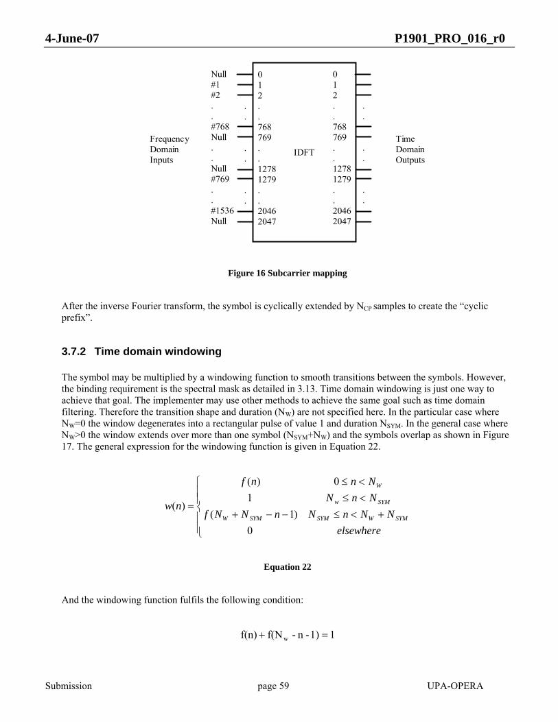
4-June-07 P1901_PRO_016_r0
Submission page 59 UPA-OPERA
IDFT
012..768769..12781279..20462047
012..768769..12781279..20462047
Null#1#2..#768Null..Null#769..#1536Null
.
.
.
.
.
.
.
.
.
.
.
.
TimeDomainOutputs
FrequencyDomainInputs
Figure 16 Subcarrier mapping
After the inverse Fourier transform, the symbol is cyclically extended by NCP samples to create the “cyclic prefix”.
3.7.2 Time domain windowing
The symbol may be multiplied by a windowing function to smooth transitions between the symbols. However, the binding requirement is the spectral mask as detailed in 3.13. Time domain windowing is just one way to achieve that goal. The implementer may use other methods to achieve the same goal such as time domain filtering. Therefore the transition shape and duration (NW) are not specified here. In the particular case where NW=0 the window degenerates into a rectangular pulse of value 1 and duration NSYM. In the general case where NW>0 the window extends over more than one symbol (NSYM+NW) and the symbols overlap as shown in Figure 17. The general expression for the windowing function is given in Equation 22.
⎪⎪⎩
⎪⎪⎨
⎧
+<≤−−+<≤<≤
=
elsewhereNNnNnNNf
NnNNnnf
nwSYMWSYMSYMW
SYMw
W
0)1(
10)(
)(
Equation 22
And the windowing function fulfils the following condition:
11)-n-f(Nf(n) w =+

4-June-07 P1901_PRO_016_r0
Submission page 60 UPA-OPERA
Equation 23
NSYM
NIFFTNCPNW
Figure 17 Windowing
The maximum duration of the window (Nw) depends on the symbol Type used:
• Type I: 128 samples
• Type II: 128 samples
• Type III: 64 samples
The OFDM symbol can be expressed in mathematical form as inEquation 24.
⎭⎬⎫
⎩⎨⎧
⎟⎠⎞
⎜⎝⎛ −−−+⎟
⎠⎞
⎜⎝⎛ −−= ∑∑
==
)(2048
2exp),510()(2048
2exp),()()(2046
1279
768
1WCP
kkWCPSYMSYMi NNnkjikcNNnkjikcnwkns ππ
Equation 24
Where
− i is the i-th OFDM symbol; i = 0, 1, …
− n is the sample index; 0 ≤ n < NSYM+NW
− kSYM is a normalization factor, that shall be chosen in order to meet the PSD and modulation accuracy requirements.
− wSYM(n) is a windowing function
− c(k,i) is the k+iNSD complex value from the subcarrier modulation block
4-June-07 P1901_PRO_016_r0
Submission page 61 UPA-OPERA
Several of these symbols are concatenated in a burst as expressed in Equation 25
∑ −=i
SYMi iNnsns )()(
Equation 25
3.8 REFERENCE SIGNALS
3.8.1 Channel reference symbol
The channel reference symbol comes before the data and control symbols. The channel reference symbol followsEquation 24 with
)exp(),( kjikc φ=
Equation 26
where φk is a random phase picked from a uniform distributed random variable between [0,2π[. The channel reference symbol gives the initial reference for the subcarrier modulation (3.6)
3.8.2 Synchronization symbol
The synchronization symbol comes before the channel reference symbol. The synchronization symbol follows Equation 24 with
⎩⎨⎧
=oddkevenkjikc k
0)exp(2),( φ
Equation 27
where φk is a random phase picked from a uniform distributed random variable between [0,2π[.
3.8.3 Start Of Transmission (SOT)
A start of transmission signal shall always be sent before the synchronization symbol. The SOT is also used as response to the different polling frames (See 4.3.5 and 4.3.6). In reception the SOT may be used for AGC. The

4-June-07 P1901_PRO_016_r0
Submission page 62 UPA-OPERA
description of the SOT generation is always based on a 40 MHz clock, independently of the symbol type used by the node. The number of active subcarriers in the SOT depends on the symbol type used.
The SOT is composed of OFDM symbols that may be generated with a complex 256-point IDFT as shown in Equation 28.
⎭⎬⎫
⎩⎨⎧
⎟⎠⎞
⎜⎝⎛+⎟
⎠⎞
⎜⎝⎛= ∑∑
−==
nkjkcnkjkcnwknsD
D
Nk
N
kDDiD 256
2exp)(2562exp)()()(
255
2255
2
1,
ππ
Equation 28
Where
− kD is a normalization factor
− wD(n) is a windowing function, that follows Equation 22 and Equation 23. The duration of the windowing function is between 6.4 μs and 8 μs depending on the transition duration and is depicted in Figure 18.
NSYM=NIFFT=256 samples
NW≤64 samples
Figure 18 SOT Windowing
− ND is 192 (Type I), 128 (Type II) or 64 (Type III), so that the frequencies occupied by the SOT are the same as for the data and control symbols.
− c(k) = exp(jφk) where φk is a random phase picked from a uniform distributed random variable between [0,2π[
Six of these symbols are concatenated to form the SOT.

4-June-07 P1901_PRO_016_r0
Submission page 63 UPA-OPERA
∑=
−=5
0, )256()(
iiDSOT insns
Equation 29
Therefore the maximum duration of the SOT (if the maximum window size is used) will be 40 μs.
3.8.4 Channel estimation symbols
The channel estimation symbols are used to estimate the channel quality at the receiver side. After the channel estimation the receiver may send a new bit-loading table to the transmitter (see 9.1.2). These symbols shall be known by the transmitter and the receiver to allow a correct estimation under all conditions. Therefore, a pseudorandom sequence generator shall be used as the modulator input instead of the output from the 4D-TCM encoder.
The pseudorandom sequence generator shall be the 11-bit PN generator with characteristic polynomial given by Equation 30.
( ) 1121 xxxf ++=
Equation 30
This symbol shall be modulated using 2 bits per subcarrier. Therefore, two 11-bit PN generators with different seeds shall be used. Figure 19 explains how the kbΔ value is formed. The SYMBOL NUMBER value is 1 for the channel reference symbol, and is incremented by 1 for every symbol there after.

4-June-07 P1901_PRO_016_r0
Submission page 64 UPA-OPERA
OUTPUTBIT 0 (LSB)
11 10 9 8 7 6 5 4 3 2 1
OUTPUTBIT 1 (MSB)
11 10 9 8 7 6 5 4 3 2 1
PN GENERATOR 0
PN GENERATOR 1
SYMBOL NUMBER(BIT 0, LSB)
SYMBOL NUMBER (BIT 1)
XOR
Δ b k (BIT 0, LSB)Δ b k (BIT 1)
Figure 19 Channel estimation symbol generation
At the beginning of each Channel estimation symbol, the registers of the PN generators shall be set with the corresponding seed given by Table 8. So, the value to be modulated in the phase increment of the first valid subcarrier of the OFDM symbol will be determined by the seeds and the appropriate symbol number. The contents of the registers of the PN generators shall be updated before calculating the phase increment for each of the next subcarriers.
Since two bits of the symbol number are XORed with the output of the PN generators, four different symbols will be generated. These four symbols will be repeated four times to create a sixteen-symbol sequence.
Seed
PN Generator 1 0x25E
PN Generator 0 0x3C1
Table 8 PN generator seeds
4-June-07 P1901_PRO_016_r0
Submission page 65 UPA-OPERA
3.9 CARRIER FREQUENCY
The complex baseband digital signal is converted to analog signal and IQ modulated. I(t) and Q(t) are the in-phase and quadrature analog signals corresponding to the real and imaginary components of the complex baseband signal respectively. The actual transmitted signal is related to them by the following relation:
)2sin()()2cos()()( tftQtftItr ccTX ππ −=
Equation 31
cf denotes the carrier centre frequency, which must be a multiple of 156.25 KHz.
3.10 COMMUNICATION MODES
Transmission modes can be defined by specifying a carrier frequency ( cf ), and symbol Type (I, II or III) and, optionally, a power mask. Any two nodes that use a common communication mode shall be able to communicate.
The carrier frequency shall be higher than the bandwidth of the baseband signal in negative frequencies in order to avoid ICI and shall place the signal bandwidth in frequencies up to 100 MHz.
3.11 PHY PARAMETER SPECIFICATION
Table 9 contains the values for the PHY parameters.
Parameter Value Description
INTER PPDU SPACE 1 189 μs See 3.2 and 4.1
INTER PPDU SPACE 2 126 μs See 3.2 and 4.1
Table 9 PHY parameter specification
4-June-07 P1901_PRO_016_r0
Submission page 66 UPA-OPERA
3.12 CLOCK SYNCHRONIZATION
3.12.1 General
Clock frequency synchronization shall be performed and must be accurate enough to allow for maximum bit loading 10 bits on all subcarriers.
3.12.2 Clock synchronisation concept
With the exception of the HE of a BPL cell, all BPL nodes belonging to the same BPL cell must adapt their clock frequency until a unique common clock frequency is reached. This common clock frequency is the reference clock frequency dictated by the HE. All other nodes (Repeaters and CPEs) of the BPL cell will synchronize their clock frequency to this reference clock frequency.
Both transmitter and receiver of a BPL node shall use the same common clock frequency.
3.12.3 System reference clock error tolerance
Without noticeable loss of performance, BPL nodes shall be able to cope with a relative clock frequency error of up to twice the maximum absolute frequency error of the system reference clock. The absolute frequency error of the system reference clock in any BPL equipment shall not exceed ±100 ppm.
3.13 TRANSMITTER ELECTRICAL SPECIFICATION
The following specification establishes the minimum transmitter technical requirements for interoperability maintaining full performance. Unless otherwise stated, transmitter specifications assume a 50 Ω load between line and neutral terminals. All transmitter output voltages as well as spurious transmissions are specified as the voltage measured at the line terminal with respect to the neutral terminal.
3.13.1 Transmit PSD
The PSD in the emission point must be compliant with regulations in effect in the country where the system is used.
The ripple in the working band shall be less than ±1 dB.
Besides there will be a transmit spectrum mask that will depend on the regulation of each country or area. All nodes shall use a configurable power masking with 1 dB of granularity in order to be compliant with that mask, achieving notches with at least 35 dBs deep
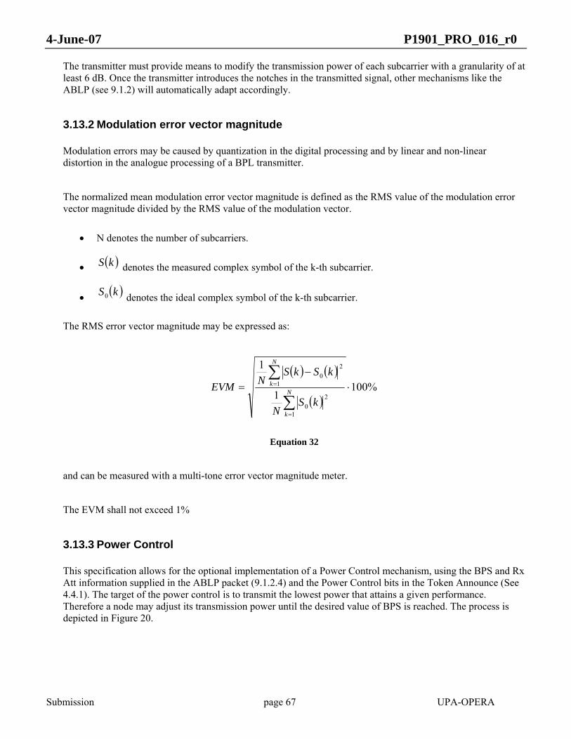
4-June-07 P1901_PRO_016_r0
Submission page 67 UPA-OPERA
The transmitter must provide means to modify the transmission power of each subcarrier with a granularity of at least 6 dB. Once the transmitter introduces the notches in the transmitted signal, other mechanisms like the ABLP (see 9.1.2) will automatically adapt accordingly.
3.13.2 Modulation error vector magnitude
Modulation errors may be caused by quantization in the digital processing and by linear and non-linear distortion in the analogue processing of a BPL transmitter.
The normalized mean modulation error vector magnitude is defined as the RMS value of the modulation error vector magnitude divided by the RMS value of the modulation vector.
• N denotes the number of subcarriers.
• ( )kS denotes the measured complex symbol of the k-th subcarrier.
• ( )kS0 denotes the ideal complex symbol of the k-th subcarrier.
The RMS error vector magnitude may be expressed as:
( ) ( )
( )%100
1
1
1
20
1
20
⋅−
=
∑
∑
=
=N
k
N
k
kSN
kSkSNEVM
Equation 32
and can be measured with a multi-tone error vector magnitude meter.
The EVM shall not exceed 1%
3.13.3 Power Control
This specification allows for the optional implementation of a Power Control mechanism, using the BPS and Rx Att information supplied in the ABLP packet (9.1.2.4) and the Power Control bits in the Token Announce (See 4.4.1). The target of the power control is to transmit the lowest power that attains a given performance. Therefore a node may adjust its transmission power until the desired value of BPS is reached. The process is depicted in Figure 20.

4-June-07 P1901_PRO_016_r0
Submission page 68 UPA-OPERA
Power Control task
Lower than Th_bottom?
Check currently negotiated bps
No
Yes
Periodically or not
Greater than Th_top?
Increase Txg Decrease Txg
Yes
No
Figure 20 Power control algorithm
3.14 RECEIVER ELECTRICAL SPECIFICATION
Unless otherwise stated, all signals are specified as the voltage measured at the line terminal with respect to the neutral terminal.
3.14.1 Receiver Input Impedance
When not transmitting, the system shall present a minimum impedance of 40 Ω in the working band, measured between line and neutral terminals.

4-June-07 P1901_PRO_016_r0
Submission page 69 UPA-OPERA
3.14.2 Receiver Input Referred Noise
The system shall present an IRN level lower than –148 dBm/Hz when it sets the maximum reception gain.
3.14.3 Receiver Input Signal
The receiver shall maintain full performance with a signal input level of 8 Vpp.
The ripple introduced by the system in the working band shall be less than ±1 dB.
The sensitivity of the receiver is defined as follows:
For an input signal with flat spectrum and using Type I OFDM symbols, the minimum input level at which the system shall receive 2 Mbps of UDP traffic with 0% PLR is:
• 0.17 mVrms
• -137 dBm/Hz referred to 50 Ω
3.15 PHY service specification (PHY SAP)
3.15.1 PHY service primitives
The following table shows PHY DATA and MNT primitives:
Primitive Type

4-June-07 P1901_PRO_016_r0
Submission page 70 UPA-OPERA
PHY-DATA.req Request PHY-DATA.cnf Confirm PHY-DATA.ind Indicate PHY-MNT-SNR.ind Indication PHY-MNT-BPC-SET.req Request PHY-MNT-BPC-SET.cnf Confirm PHY-MNT-BPC-GET.req Request PHY-MNT-BPC-GET.cnf Confirm PHY-MNT-RXGAIN-GET.req Request PHY-MNT-RXGAIN-GET.cnf Confirm PHY-MNT-TXGAIN-SET.req Request PHY-MNT-TXGAIN-SET.cnf Confirm PHY-MNT-TXGAIN-GET.req Request PHY-MNT-TXGAIN-GET.cnf Confirm PHY-MNT-POWMASK-GET.req Request PHY-MNT-POWMASK-GET.cnf Confirm PHY-MNT-POWMASK-SET.req Request PHY-MNT-POWMASK-SET.cnf Confirm PHY-MNT-SYNC.ind Indication PHY-MNT-SYNC.req Request PHY-MNT-SYNC.cnf Confirm
Table 10 PHY SAP primitives
3.15.2 PHY service primitives parameters
The following table shows PHY DATA and MNT parameters:
Parameter Associated Primitive Value

4-June-07 P1901_PRO_016_r0
Submission page 71 UPA-OPERA
MPDU PHY-DATA.req PHY-DATA.ind
MAC Protocol Data Unit
snr_measure, port PHY-MNT-SNR.ind SNR measure with remote node in Rx Rx port of the remote transmitter node
bpc_type, port, tonemap PHY-MNT-BPC-SET.req PHY-MNT-BPC-SET.cnf PHY-MNT-BPC-GET.cnf
Tx, Rx Tx or Rx port Updated tonemap
bpc_type, port PHY-MNT-BPC-GET.req Tx, Rx Local Tx or Rx port
port PHY-MNT-RXGAIN-GET.req Local Rx port port PHY-MNT-TXGAIN-GET.req
PHY-MNT-TXGAIN-SET.cnf PHY-MNT-POWMASK-GET.req PHY-MNT-POWMASK-SET.cnf PHY-MNT-LINK-STATUS.req PHY-MNT-LINK-STATUS.cnf
Local Tx port
port, gain PHY-MNT-RXGAIN-GET.cnf Local Rx port [0-7] Rx gain level
port, gain PHY-MNT-TXGAIN-GET.cnf PHY-MNT-TXGAIN-SET.req
Local Tx port Tx gain
port, pow_mask PHY-MNT-POWMASK-GET.cnf PHY-MNT-POWMASK-SET.req
Local Tx port Tx power mask
sync_type, mode PHY-MNT-SYNC.ind [sync|sync _lost] The Tx / Rx signal mode
mode, timeout PHY-MNT-SYNC.req The Tx / Rx signal mode Time to sense the channel
Mode, result PHY-MNT-SYNC.cnf The Tx/Rx signal mode Success/fail
Table 11 PHY SAP parameters
Legend : Tx = Transmission Rx = Reception
3.15.3 PHY-DATA.req
3.15.3.1 Function
This primitive requests a transfer of a MPDU from a local MAC layer entity.

4-June-07 P1901_PRO_016_r0
Submission page 72 UPA-OPERA
3.15.3.2 Semantics of the service primitive
PHY-DATA.req(MPDU):
• MPDU: MAC Protocol Data Unit
3.15.3.3 When generated
The primitive is generated by the MAC layer entity when a MPDU is to be transferred.
3.15.3.4 Effect of receipt
The PHY layer entity starts the sending of the MPDU.
3.15.4 PHY-DATA.cnf
3.15.4.1 Function
This primitive has local significance and provides the MAC layer with status information (sending finished) of the corresponding preceeding PHY-DATA.req primitive.
3.15.4.2 Semantics of the service primitive
This primitive has no parameters.
3.15.4.3 When generated
The primitive is passed from the PHY layer entity to the MAC layer entity to indicate that the previous MPDU has been sent and the PHY layer is available to send new MPDUs.
3.15.4.4 Effect of receipt
The MAC layer entity is aware that the PHY is available to send new MPDUs, and can issue new PHY-DATA.req primitives.
3.15.5 PHY-DATA.ind
3.15.5.1 Function
This primitive defines the transfer of a received MPDU from the PHY layer entity to the MAC layer entity.
4-June-07 P1901_PRO_016_r0
Submission page 73 UPA-OPERA
3.15.5.2 Semantics of the service primitive
PHY-DATA.ind(MPDU):
• MPDU: MAC Protocol Data Unit.
3.15.5.3 When generated
The primitive is passed from the PHY layer entity to the MAC layer entity to indicate the arrival of a MPDU.
3.15.5.4 Effect of receipt
The MAC layer entity processes the newly received MPDU.
3.15.6 PHY-MNT-SNR.ind
3.15.6.1 Function
This primitive indicates that the Physical layer entity has done a SNR measure with another node, and defines the transfer of the SNR measure to the Management layer entity.
3.15.6.2 Semantics of the service primitive
PHY-MNT-SNR.ind (snr_measure, port):
• snr_measure: SNR measure with remote node in reception • port: reception port of the remote transmitter node
3.15.6.3 When generated
The primitive is generated when the node measures the SNR with another node which transmitted an SNR frame.
3.15.6.4 Effect of receipt
The Management layer entity will decide if the tonemap must be changed for that port depending on the new snr_measure and the current tonemap. If the tonemap must change, an ABLP message shall be sent to the other node by means of the ETH.req primitive.
3.15.7 PHY-MNT-BPC-SET.req
3.15.7.1 Function
This primitive request the change of the tonemap used to transmit/receive to/from a remote node.

4-June-07 P1901_PRO_016_r0
Submission page 74 UPA-OPERA
3.15.7.2 Semantics of the service primitive
PHY-MNT-BPC-SET.req (bpc_type, port, tonemap)
• bpc_type: tx, rx (transmission, reception) • port: transmission or reception port • tonemap: updated tonemap to be used
3.15.7.3 When generated
The primitive is generated when the transmission/reception tonemap table with a node must be changed according to the ABLP protocol
3.15.7.4 Effect of receipt
The tonemap used by the Physiscal layer to transmit/receive to/from a remote node is changed.
3.15.8 PHY-MNT-BPC-SET.cnf
3.15.8.1 Function
This primitive informs the Management layer that the tonemap has been updated.
3.15.8.2 Semantics of the service primitive
PHY-MNT-BPC-SET.cnf (bpc_type, port, tonemap)
• bpc_type: tx, rx (transmission, reception) • port: transmission or reception port • tonemap: updated tonemap
3.15.8.3 When generated
The primitive is generated by the Physical layer to confirm the Management layer that the tonemap has been updated.
3.15.8.4 Effect of receipt
Management layer can use the updated tonemap for throughput and class of service calculations.

4-June-07 P1901_PRO_016_r0
Submission page 75 UPA-OPERA
3.15.9 PHY-MNT-BPC-GET.req
3.15.9.1 Function
This primitive requests the tonemap used to transmit/receive to/from a remote node.
3.15.9.2 Semantics of the service primitive
PHY-MNT-BPC-GET.req (bpc_type, port) :
• bpc_type: tx, rx • port: local transmission or reception port
3.15.9.3 When generated
The primitive is generated when the Management layer needs to know the current tonemap used to transmit/receive to/from a remote node.
3.15.9.4 Effect of receipt
The current tonemap is read by the Physical layer and passed to the Management layer by means of the PHY-MNT-BPC-GET.cnf primitive.
3.15.10 PHY-MNT-BPC-GET.cnf
3.15.10.1 Function
This primitive indicates the result of the previously requested tonemap.
3.15.10.2 Semantics of the service primitive
PHY-MNT-BPC-GET.cnf (bpc_type, port, tonemap)
• bpc_type: tx, rx • port: local transmission or reception port • tonemap: current tonemap
3.15.10.3 When generated
The primitive is passed by the Physical layer entity to the Management layer entity to provide the requested tonemap.
4-June-07 P1901_PRO_016_r0
Submission page 76 UPA-OPERA
3.15.10.4 Effect of receipt
The Maganement layer receives the tonemap.
3.15.11 PHY-MNT-RXGAIN-GET.req
3.15.11.1 Function
This primitive requests the Physical layer the reception gain being used to receive from a remote node.
3.15.11.2 Semantics of the service primitive
PHY-MNT-RXGAIN-GET.req (port):
• port: reception port
3.15.11.3 When generated
The primitive is generated when the Management layer needs to know the reception gain being used in reception with another node.
3.15.11.4 Effect of receipt
The current reception gain is obtained by the Physical layer and passed to the Management layer by means of the PHY-MNT-RXGAIN-GET.cnf primitive.
3.15.12 PHY-MNT-RXGAIN-GET.cnf
3.15.12.1 Function
This primitive indicates the result of the previously requested reception gain.
3.15.12.2 Semantics of the service primitive
PHY-MNT-RXGAIN-GET.cnf (port, gain):
• port: reception port • gain: reception gain level
3.15.12.3 When generated
The primitive is passed by the Physical layer entity to the Management layer entity to provide the requested reception gain.
4-June-07 P1901_PRO_016_r0
Submission page 77 UPA-OPERA
3.15.12.4 Effect of receipt
The Maganement layer gets the reception gain. It can be used in protocols such as the Access protocol or the Net Configuration protocol.
3.15.13 PHY-MNT-TXGAIN-GET.req
3.15.13.1 Function
This primitive requests the Physical layer the transmission gain being used to transmit to a remote node.
3.15.13.2 Semantics of the service primitive
PHY-MNT-TXGAIN-GET.req (port):
• port: local transmission port
3.15.13.3 When generated
The primitive is generated when the Management layer needs to know the transmission gain being used in transmission with another node.
3.15.13.4 Effect of receipt
The current transmission gain is obtained by the Physical layer and passed to the Management layer by means of the PHY-MNT-TXGAIN-GET.cnf primitive.
3.15.14 PHY-MNT-TXGAIN-GET.cnf
3.15.14.1 Function
This primitive indicates the result of the previously requested transmission gain.
3.15.14.2 Semantics of the service primitive
PHY-MNT-TXGAIN-GET.cnf (port, gain):
• port: local transmission port • gain: transmission gain level
3.15.14.3 When generated
The primitive is passed by the Physical layer entity to the Management layer entity to provide the requested transmission gain.

4-June-07 P1901_PRO_016_r0
Submission page 78 UPA-OPERA
3.15.14.4 Effect of receipt
The Maganement layer gets the transmission gain.
3.15.15 PHY-MNT-TXGAIN-SET.req
3.15.15.1 Function
This primitive request the change of the transmission gain used to transmit to a remote node.
3.15.15.2 Semantics of the service primitive
PHY-MNT-TXGAIN-SET.req (port, gain):
• port: local transmission port • gain: transmission gain level
3.15.15.3 When generated
This primitive must be generated when the Management layer wants to change the transmission gain with a given node.
3.15.15.4 Effect of receipt
The Physical layer updates the transmission gain with the indicated port. It shall confirm the action.
3.15.16 PHY-MNT-TXGAIN-SET.cnf
3.15.16.1 Function
This primitive acknowledges the previously requested action.
3.15.16.2 Semantics of the service primitive
PHY-MNT-TXGAIN-SET.cnf (port):
• Port: local transmission port.
3.15.16.3 When generated
This primitive is generated by the Physical layer when it updates the transmission gain.

4-June-07 P1901_PRO_016_r0
Submission page 79 UPA-OPERA
3.15.16.4 Effect of receipt
The Management layer receives the confirmation of the change.
3.15.17 PHY-MNT-POWMASK-GET.req
3.15.17.1 Function
This primitive requests the Physical layer the power mask being used to transmit to a remote node.
3.15.17.2 Semantics of the service primitive
PHY-MNT-POWMASK-GET.req (port):
• port: local transmission port
3.15.17.3 When generated
The primitive is generated when the Management layer want to know the power mask being used in transmission with another node.
3.15.17.4 Effect of receipt
The current power mask is obtained by the Physical layer and passed to the Management layer by means of the PHY-MNT-POWMASK-GET.cnf primitive
3.15.18 PHY-MNT-POWMASK-GET.cnf
3.15.18.1 Function
This primitive indicates the result of the previously requested power mask.
3.15.18.2 Semantics of the service primitive
PHY-MNT-POWMASK-GET.cnf (port, pow_mask):
• port: local transmission port • pow_mask: transmission power mask
3.15.18.3 When generated
The primitive is passed by the Physical layer entity to the Management layer entity to provide the requested power mask.

4-June-07 P1901_PRO_016_r0
Submission page 80 UPA-OPERA
3.15.18.4 Effect of receipt
The Maganement layer receives the power mask.
3.15.19 PHY-MNT-POWMASK-SET.req
3.15.19.1 Function
This primitive request the change of the power mask used to transmit to a remote node.
3.15.19.2 Semantics of the service primitive
PHY-MNT-POWMASK-SET.req (port, pow_mask)
• port: local transmission port • pow_mask: transmission power mask
3.15.19.3 When generated
This primitive must be generated when the Management layer wants to change the transmission power mask with a given node.
3.15.19.4 Effect of receipt
The Physical layer updates the transmission power mask with the indicated port. It shall confirm the action.
3.15.20 PHY-MNT-POWMASK-SET.cnf
3.15.20.1 Function
This primitive acknowledges the previously requested action.
3.15.20.2 Semantics of the service primitive
PHY-MNT-POWMASK-SET.cnf (port):
• port: local transmission port.
3.15.20.3 When generated
This primitive is generated by the Physical layer when it updates the transmission power mask.

4-June-07 P1901_PRO_016_r0
Submission page 81 UPA-OPERA
3.15.20.4 Effect of receipt
The Management layer receives the confirmation of the change.
3.15.21 PHY-MNT-SYNC.ind
3.15.21.1 Function
This primitive is generated by the Physical layer to notify a synchronization detection event to the Management layer. It provides status information.
3.15.21.2 Semantics of the service primitive
PHY-MNT-SYNC.ind (sync_type, mode) :
• sync_type= [sync|sync_loss] • mode: the transmission/reception signal mode
3.15.21.3 When generated
The primitive is passed by the Physical layer to the Management layer to inform about a synchronization event. This event can be positive (synchronization symbol detected) or negative (synchronization symbol not detected when it was expected).
3.15.21.4 Effect of receipt
When receiving a "sync" event, the Management layer can infer that a synchronization symbol has been detected in the transmission mode “mode”. When receiving a “sync_loss” event, the Management layer can infer that an expected synchronization symbol has not been detected. This information can be used by the Management layer to take decisions regarding the configuration of the BPL cell.
3.15.22 PHY-MNT-SYNC.req
3.15.22.1 Function
This primitive requests the Physical layer to detect synchronization symbols.
3.15.22.2 Semantics of the service primitive
PHY-MNT-SYNC.req (mode,timeout) :
• mode: the transmission/reception signal mode. • timeout: maximum time to sense the channel

4-June-07 P1901_PRO_016_r0
Submission page 82 UPA-OPERA
3.15.22.3 When generated
The primitive is generated by the Management layer to detect if there is activity in the channel using the given transmission mode.
3.15.22.4 Effect of receipt
The Physical layer senses the channel during the “timeout” time. When a synchronization symbol is detected or the “timeout” expires, the result is notified to the Management layer by means of the PHY-MNT-SYNC.cnf primitive.
3.15.23 PHY-MNT-SYNC.cnf
3.15.23.1 Function
This primitive acknowledges the previously requested action and provides the requested information.
3.15.23.2 Semantics of the service primitive
PHY-MNT-SYNC.cnf (mode, result):
• mode: transmission/reception signal mode • result: success/fail
3.15.23.3 When generated
The Physical layer generates this primitive when a synchronization symbol is detected (success) or when the “timeout” expires (fail).
3.15.23.4 Effect of receipt
This information is required by the Net Configuration protocol to check if there are other nodes in the channel.
PHY-MNT- PHY-MNT-LINK-STATUS.req
4 MAC
4.1 OVERVIEW
The IEEE P1901 MAC is based on a TDMA/TDD MAC with hybrid resource sharing mechanisms built on top of an OFDM PHY layer. Data are encapsulated inside OFDM symbols. The control and data symbols transmitted consecutively by a single node constitute a transmission frame.
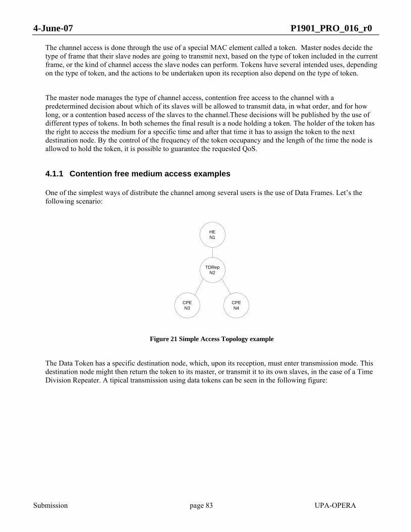
4-June-07 P1901_PRO_016_r0
Submission page 83 UPA-OPERA
The channel access is done through the use of a special MAC element called a token. Master nodes decide the type of frame that their slave nodes are going to transmit next, based on the type of token included in the current frame, or the kind of channel access the slave nodes can perform. Tokens have several intended uses, depending on the type of token, and the actions to be undertaken upon its reception also depend on the type of token.
The master node manages the type of channel access, contention free access to the channel with a predetermined decision about which of its slaves will be allowed to transmit data, in what order, and for how long, or a contention based access of the slaves to the channel.These decisions will be published by the use of different types of tokens. In both schemes the final result is a node holding a token. The holder of the token has the right to access the medium for a specific time and after that time it has to assign the token to the next destination node. By the control of the frequency of the token occupancy and the length of the time the node is allowed to hold the token, it is possible to guarantee the requested QoS.
4.1.1 Contention free medium access examples
One of the simplest ways of distribute the channel among several users is the use of Data Frames. Let’s the following scenario:
HEN1
CPEN4
TDRepN2
CPEN3
Figure 21 Simple Access Topology example
The Data Token has a specific destination node, which, upon its reception, must enter transmission mode. This destination node might then return the token to its master, or transmit it to its own slaves, in the case of a Time Division Repeater. A tipical transmission using data tokens can be seen in the following figure:

4-June-07 P1901_PRO_016_r0
Submission page 84 UPA-OPERA
Time
N1 TX
N2 TX
N3 TX
N4 TX
Token for N2
Token for N2
Token for N1
Token for N2
Token for N4
Token for N3
Downstream token
Upstream token
IPPD
U1
IPPD
U1
IPP
DU
1
IPPD
U1
IPPD
U1
Data PPDU
Figure 22 Transmission sequence
When N2 receives the token from its master, it is this node that must decide what nodes will follow: in this case, it transmits it to each of its slaves, and finally returns it to its master. Any other kind of sequence would be possible, and it is the master, at each level, who decides how the token, and thus the slots of time, will be divided amongst the rest of the nodes.
On the other hand, the order of transmission can be predesigned using the so called distributor token. The transmission sequence can took place in the following topology:
Figure 23 Topology example

4-June-07 P1901_PRO_016_r0
Submission page 85 UPA-OPERA
The following diagram ¡Error! No se encuentra el origen de la referencia.depicts a transmission sequence using this kind of token. As it is outlined in the above diagram, a transmission sequence starts with a Distributor Token. This type of token assigns the channel to a list of nodes. The Data Token is used by slaves to release the token to the next detination node. Further sections describe this diagram in more detail.
DISTRIBUTORTOKEN
MASTER
Slave 1
Slave 3
Slave 4 DATATOKEN to Slave 2
List InfoDst1 = Slave 1 Validity1 SessionId1Dst2 = Slave 4 Validity2 SessionId2
Dst3 = Slave 3 Validity3 SessionId3 Dst4 = Slave 2 Validity4 SessionId4
Slave 2
DATA TOKENto MASTER≤ Validity3
≤ Validity4
DATA TOKENTo Slave 4
≤ Valitdity1
DISTRIBUTORTOKEN
DATAFrom SessionId4
DATA TOKEN to Slave 3
DATAFrom SessionId3
DATAFrom SessionId1
IPPDUS1 IPPDUS2 IPPDUS2IPPDUS2 IPPDUS2
DATAFrom SessionId2
≤ Valitdity2
Figure 24: Transmission Sequence
Using the previously described channel access, a programmed timming interval can be set, synchronized or not with the mains meriod using the clock token, where several nodes in a preestablished order can transmit.
4.1.2 Contention medium access example
In the previous examples, the destination of the token, and so, the next token holder is explicity defined in the information that the token contains. In the case of CSMA or Access Replay frame, the next token holder is not predefined by the node that transmit the token, but a priorized contention period is open to decide the node that will be the next token holder.
Asume again the topology described in Figure 23.
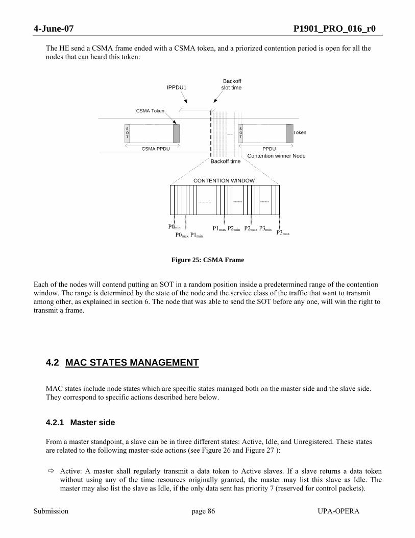
4-June-07 P1901_PRO_016_r0
Submission page 86 UPA-OPERA
The HE send a CSMA frame ended with a CSMA token, and a priorized contention period is open for all the nodes that can heard this token:
P0max P1min
P2max P3min
CONTENTION WINDOW
P1max P2min P3max
CSMA Token
IPPDU1Backoff
slot time
SOT
CSMA PPDU
Backoff time
P0min
SOT
PPDU
Token
Contention winner Node
Figure 25: CSMA Frame
Each of the nodes will contend putting an SOT in a random position inside a predetermined range of the contention window. The range is determined by the state of the node and the service class of the traffic that want to transmit among other, as explained in section 6. The node that was able to send the SOT before any one, will win the right to transmit a frame.
4.2 MAC STATES MANAGEMENT
MAC states include node states which are specific states managed both on the master side and the slave side. They correspond to specific actions described here below.
4.2.1 Master side
From a master standpoint, a slave can be in three different states: Active, Idle, and Unregistered. These states are related to the following master-side actions (see Figure 26 and Figure 27 ):
Active: A master shall regularly transmit a data token to Active slaves. If a slave returns a data token without using any of the time resources originally granted, the master may list this slave as Idle. The master may also list the slave as Idle, if the only data sent has priority 7 (reserved for control packets).

4-June-07 P1901_PRO_016_r0
Submission page 87 UPA-OPERA
Idle: No data token is transmitted to an Idle slave, that is to say this slave does not get any scheduled transmission opportunity until it is required. This feature reduces the transmission of empty frames by non active slaves and it also increases the network performance, since the transmission opportunities not given to Idle slaves can be used by other Active users. A master shall regularly transmit Polling Frames to an Idle slave. This management is done in a different way and with different token depending on the type of the slaves: TDRs or CPEs.
o When the Idle slave is a CPE, the master shall poll it to check if it has data to transmit from a service class different from number 7 (See 8). If yes, it must be considered Active again. If answer is no, it shall be considered registered, although it has no data of higher service class to transmit. When the CPE has no activity, that means, no data is transmitted during long times, must be considered as Unregistered. This information is obtained by means of two different types of Polling Tokens: Active Polling Tokens and Alive Polling Tokens respectively. Up to 32 CPEs can be polled with only one of these Polling Frames.
Active Polling Tokens shall be regularly transmitted by the master to manage transitions from Idle to Active. A slave which replies to an Active Polling Token shall be listed as Active by its master. A master is constrained to transmit an Active Polling Token with a maximum interval equal to MAX_ACTIVE_POLL_INTERVAL.
Alive Polling Tokens shall be regularly transmitted by the master to manage transitions from Idle to Unregistered. A master is constrained to transmit an Alive Polling Token with a maximum interval equal to MAX_ALIVE_POLL_INTERVAL. A slave which does not reply to a number of Alive polling tokens equal to MAX_ALIVE_TOKENS shall be listed as Unregistered.
o When the slave is a TDR, the master shall only consider it as Idle when neither it nor any of the slaves in its BPL sub-tree are transmitting or receiving data of service class 1 to 6; this information is available in the field Frame Priority sent in the Data Token (see 0). The management of idle TDRs from the master side is slightly different from idle CPEs, although the concept stays the same. The reason for these differences is that TDRs shall provide some periodic services to the users in their BPL sub-tree and to other non-registered users within their visibility area apart from notifying if they have traffic to send. The master shall send a TDR Polling Frame to every Idle TDR connected to it as a slave, with a maximum interval equal to MAX_ACTIVE_POLL_INTERVAL.
The master shall give enough validity in this polling token for the TDR to send at least an Access Frame every MAC_ACCESS_INTERVAL, as many Polling Frames to CPEs as required (from 0 to 4, depending on the number of banks needed) every MAX_ACTIVE_POLL_INTERVAL and as many TDR Polling Frames as TDRs connected to it as slaves every MAX_ACTIVE_POLL_INTERVAL. The validity should be calculated from the topology information provided by the Cluster Discovery Protocol (see 0).
A TDR that does not reply a number of consecutive TDR Polling Tokens equal to MAX_ALIVE_TOKENS shall be listed as Unregistered.
4-June-07 P1901_PRO_016_r0
Submission page 88 UPA-OPERA
Note: If a master has pending downstream data for an Idle slave belonging to a service class different from 7, the master may automatically switch the status of this slave into Active and start giving it transmission opportunities.
Unregistered: An Unregistered slave is not explicitly managed by a master. However, the master is constrained to regularly broadcast access frames to discover/recover Unregistered slaves. The maximum transmission interval of these access frames is MAX_ACCESS_INTERVAL.
The HE should also turn Idle itself when it has no users or all its users are Idle during a period, in order to reduce to the minimum the electromagnetic interference and the power consumption.
This requirement implies stopping all MAC activity when the whole network is idle except for the transmissions of Access Frames and Active, Alive and TDR Polling Frames, which shall be made at least within the specified intervals.
The HE shall switch to Active status, when any of these situations occurs:
• automatically, if it has data from service class different from 7 to transmit to any user, • after sending an Active Polling Frame or a TDR Polling Frame, if any of its slaves (TDRs and/or CPEs)
replies affirmatively and • after sending an Access Request Frame if any user replies to it, so that the Access Protocol process can
be started.
4.2.2 Slave side
4.2.2.1 CPE side
From a slave standpoint, a CPE can be in two different states: Registered or Unregistered (see Figure 28 )
Unregistered: This is the initial state of a slave. An unregistered slave is only authorized to answer access frames as required by the access protocol. When the access protocol process is completed and successful, the slave enters the Registered state.
Registered: The following specific requirements apply to this state:
o A Registered CPE shall never reply to access frames from its current master. It might reply to access frames from another master if it wishes to change its current master.
o A Registered CPE shall not reply to an Active polling token if it has no need for network resources.
o A Registered CPE that wishes to continue in that state shall always reply to an Alive polling token.
o A Registered CPE which has not received any Alive polling token or Data token for more than MAX_ALIVE_TOKENS*MAX_ALIVE POLL_INTERVAL shall enter the Unregistered state. The counting of this time interval shall be initialized at the end of the last polling slot in which the slave has asserted a SOT or at the reception of the last Data Token received by the Registered slave, whichever is later.

4-June-07 P1901_PRO_016_r0
Submission page 89 UPA-OPERA
4.2.2.2 TDR side
From a slave standpoint, a TDR can be in two different states: Registered or Unregistered (see Figure 27).
Unregistered: This is the initial state of a slave. An unregistered slave is only authorized to answer access frames as required by the access protocol. When the access protocol process is completed and successful, the slave enters the Registered state.
Registered: The following specific requirements apply to this state:
o A Registered TDR shall never reply to access frames from its current master. It might reply to access frames from another master if it wishes to change its current master.
o A Registered TDR, at the reception of a TDR Polling Frame, shall ensure to transmit Access Frames, Polling Frames and TDR Polling Frames for all its slaves in the maximum specified intervals (see 4.6). Afterwards, the TDR shall reply to the TDR Polling Frame sent by the master indicating whether it wants to be Active or it wants to stay Idle but still Registered.
o An Registered TDR, in Idle state, shall not transmit any Data Token. It shall no transmit any data either, except for service class 7 traffic. Nevertheless, the TDR could transmit data in the TDR Polling Reply Frame when it indicates that it wants to be Active again, if it has enough remaining validity for it.
o A Registered TDR which has not received any TDR Polling Token or Data Token for more than MAX_ALIVE_TOKENS*MAX_ACTIVE POLL_INTERVAL shall enter the Unregistered state. The counting of this time interval shall be initialized at the end of the TDR Polling Reply symbol sent or at the reception of the last Data Token received by the Registered slave, whichever is later.
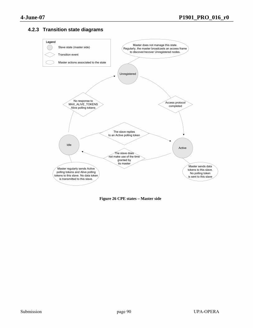
4-June-07 P1901_PRO_016_r0
Submission page 90 UPA-OPERA
4.2.3 Transition state diagrams
Unregistered
ActiveIdle
Master regularly sends Active polling tokens and Alive polling
tokens to this slave. No data token is transmitted to this slave.
Master sends data tokens to this slave.
No polling token is sent to this slave
The slave doesnot make use of the time
granted by its master
The slave replies to an Active polling token
No response to MAX_ALIVE_TOKENS
Alive polling tokens
Master does not manage this state. Regularly, the master broadcasts an access frame
to discover/recover Unregistered nodes.Transition event
Master actions associated to the state
Legend
Slave state (master side)
Access protocol completed
Figure 26 CPE states – Master side
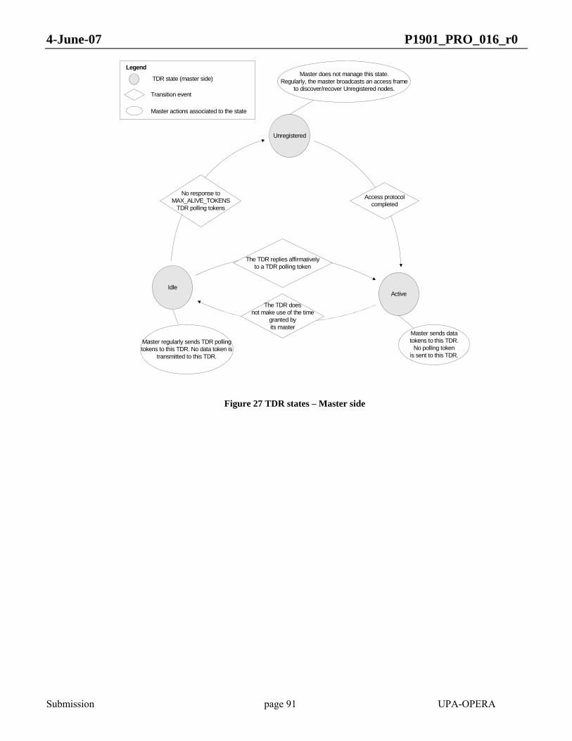
4-June-07 P1901_PRO_016_r0
Submission page 91 UPA-OPERA
Unregistered
ActiveIdle
Master regularly sends TDR polling tokens to this TDR. No data token is
transmitted to this TDR.
Master sends data tokens to this TDR.
No polling token is sent to this TDR.
The TDR doesnot make use of the time
granted by its master
The TDR replies affirmativelyto a TDR polling token
No response to MAX_ALIVE_TOKENS
TDR polling tokens
Master does not manage this state. Regularly, the master broadcasts an access frame
to discover/recover Unregistered nodes.Transition event
Master actions associated to the state
Legend
TDR state (master side)
Access protocol completed
Figure 27 TDR states – Master side

4-June-07 P1901_PRO_016_r0
Submission page 92 UPA-OPERA
Unregistered
Registered
The slave shall never reply to access frames from its master. It might answer access
frames from another master if it wishes to change of master.
Access protocol process completed
No response to/ No reception of Alive Polling tokens for
MAX_ALIVE_TOKENS*MAX_ALIVE_POLL_INTERVAL
Transition event
Slave actions associated to the state
Legend
The slave shall only reply to access frames as required by
the access protocol
Slave state (slave side)
Figure 28 Slave states – Slave side
4.3 FRAME FORMATS
A frame corresponds to an MPDU passed by the MAC layer to the PHY layer. There are two types of MPDUs: regular MPDUs and Channel Estimation MPDUs.
Regular MPDUs can encapsulate bursts provided by the LLC layer.
Channel Estimation MPDUs are directly triggered by the MAC layer; they carry a specific signal sequence generated by the PHY layer: Channel Estimation MPDUs do not encapsulate any burst provided by the LLC layer.
Regular MPDU:
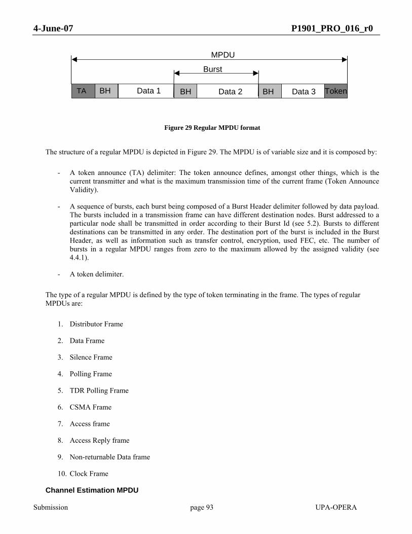
4-June-07 P1901_PRO_016_r0
Submission page 93 UPA-OPERA
BH Data 1 Data 2 BH Data 3
Burst
MPDU
TA BH Token
Figure 29 Regular MPDU format
The structure of a regular MPDU is depicted in Figure 29. The MPDU is of variable size and it is composed by:
- A token announce (TA) delimiter: The token announce defines, amongst other things, which is the current transmitter and what is the maximum transmission time of the current frame (Token Announce Validity).
- A sequence of bursts, each burst being composed of a Burst Header delimiter followed by data payload. The bursts included in a transmission frame can have different destination nodes. Burst addressed to a particular node shall be transmitted in order according to their Burst Id (see 5.2). Bursts to different destinations can be transmitted in any order. The destination port of the burst is included in the Burst Header, as well as information such as transfer control, encryption, used FEC, etc. The number of bursts in a regular MPDU ranges from zero to the maximum allowed by the assigned validity (see 4.4.1).
- A token delimiter.
The type of a regular MPDU is defined by the type of token terminating in the frame. The types of regular MPDUs are:
1. Distributor Frame
2. Data Frame
3. Silence Frame
4. Polling Frame
5. TDR Polling Frame
6. CSMA Frame
7. Access frame
8. Access Reply frame
9. Non-returnable Data frame
10. Clock Frame
Channel Estimation MPDU

4-June-07 P1901_PRO_016_r0
Submission page 94 UPA-OPERA
All MPDUs follow the sequence described above except for the Channel Estimation Frame: this frame does not contain neither bursts nor token. It starts with a Token Announce delimiter followed by a sequence of channel estimation symbols.
4.3.1 Distributor Frame
This frame ends with a Distributor Token. This Token assigns the channel to a list of nodes (distribution list) indicating the transmission order of the nodes, the session allowed to transmit and the channel time assigned to each of them.
Nodes included in the distributor list shall transmit in the indicated order. First node on the distribution list starts transmitting using the session (see 8.1) and for the maximum time indicated in the Distributor Token. When it ends transmitting, it assigns the channel to the subsequent node on the distribution list using the Data Token.
When second node on the distribution list receives a Data Token from the first node, it starts transmitting from the session and for the maximum time indicated in the Distributor Token. When this node ends transmitting, it assigns the channel to the third node on the distribution list. This process is repeated until the last node on the distribution list returns the channel to the Master node. At this point, the master will be able to transmit a new frame of the desired type.
Master node can configure the distribution list with a maximum number of five nodes.
The holder token node can assign the channel to the desired nodes during its assigned channel time. In this way, a repeater node can transmit another Distributor token to its slave nodes or it can assign the channel to a CPE.
Following time diagram shows the described process in a scenario with four nodes (see Figure 23).
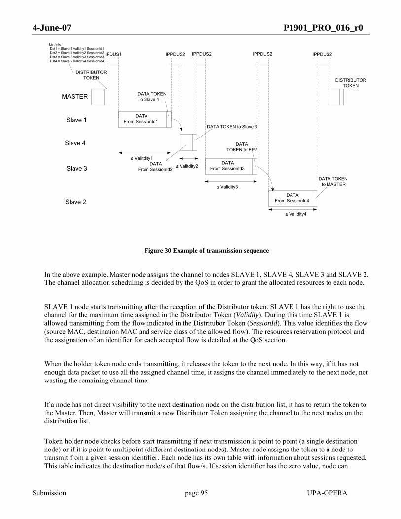
4-June-07 P1901_PRO_016_r0
Submission page 95 UPA-OPERA
DISTRIBUTORTOKEN
MASTER
Slave 1
Slave 3
Slave 4 DATATOKEN to EP2
List InfoDst1 = Slave 1 Validity1 SessionId1Dst2 = Slave 4 Validity2 SessionId2
Dst3 = Slave 3 Validity3 SessionId3 Dst4 = Slave 2 Validity4 SessionId4
Slave 2
DATA TOKENto MASTER≤ Validity3
≤ Validity4
DATA TOKENTo Slave 4
≤ Valitdity1
DISTRIBUTORTOKEN
DATAFrom SessionId4
DATA TOKEN to Slave 3
DATAFrom SessionId3
DATAFrom SessionId1
IPDUS1 IPPDUS2 IPPDUS2IPPDUS2 IPPDUS2
DATAFrom SessionId2
≤ Valitdity2
Figure 30 Example of transmission sequence
In the above example, Master node assigns the channel to nodes SLAVE 1, SLAVE 4, SLAVE 3 and SLAVE 2. The channel allocation scheduling is decided by the QoS in order to grant the allocated resources to each node.
SLAVE 1 node starts transmitting after the reception of the Distributor token. SLAVE 1 has the right to use the channel for the maximum time assigned in the Distributor Token (Validity). During this time SLAVE 1 is allowed transmitting from the flow indicated in the Distritubor Token (SessionId). This value identifies the flow (source MAC, destination MAC and service class of the allowed flow). The resources reservation protocol and the assignation of an identifier for each accepted flow is detailed at the QoS section.
When the holder token node ends transmitting, it releases the token to the next node. In this way, if it has not enough data packet to use all the assigned channel time, it assigns the channel immediately to the next node, not wasting the remaining channel time.
If a node has not direct visibility to the next destination node on the distribution list, it has to return the token to the Master. Then, Master will transmit a new Distributor Token assigning the channel to the next nodes on the distribution list.
Token holder node checks before start transmitting if next transmission is point to point (a single destination node) or if it is point to multipoint (different destination nodes). Master node assigns the token to a node to transmit from a given session identifier. Each node has its own table with information about sessions requested. This table indicates the destination node/s of that flow/s. If session identifier has the zero value, node can

4-June-07 P1901_PRO_016_r0
Submission page 96 UPA-OPERA
transmit to different nodes in the same transmission. Usually, this type of transmission will be only performed for low service class traffic.
As it is described in the above time diagram, Inter PPDU Space (IPPDUSx) depends on the type of the next frame to be transmitted. In the MAC Parameters Section, it is detailed the value of each Inter PPDU Space.
4.3.2 Data Frame
When a data frame is transmitted from a master to one of its slaves (the direction of the token is downstream), the data token at the end of the data frame will indicate for how long the slave is allowed to transmit. This length of time is known as the token validity, and is expressed as a number of symbols. The maximum length of the data frame is limited by the validity.
Upon transmitting a data token, the node will enter reception mode.
When a CPE receives a data token, it may transmit a data frame for as long as the received data token validity indicated. At the end of the frame, a data token is transmitted indicating the end of the transmission. At this point, the master node will take over the channel again.
When a Time Division Repeater (TDR) receives a data token from its master node, it schedules the transmissions between itself and the master node and also distributes new tokens among its slaves, for as long as the received data token validity indicated.
The validity does not need to be fully used by the receiving node, and it will not be wasted: the validity only sets the maximum length of time between the transmission of a token downstream and the return of this token, and it does not reflect the actual length.
4.3.3 Silence Frame
A node transmits the silence frame when it does not want to transmit the token to another node at the end of the frame or when no other kind of frames can be sent (or need to be sent). A silence frame may contain bursts with payload data. Upon transmitting a silence token, the node shall transmit a new frame.
For instance, the silence frame may be used by a HE node that is alone in the network. In that situation it shall send periodical access frames, and silence frames will cover the rest of the time. Another use is when the bursts to be transmitted do not fit in one single MPDU. In such a case it is possible to transmit several consecutive silence frames and a final data frame to pass the token to another node.
Upon reception of a silence token, no action needs to be done.
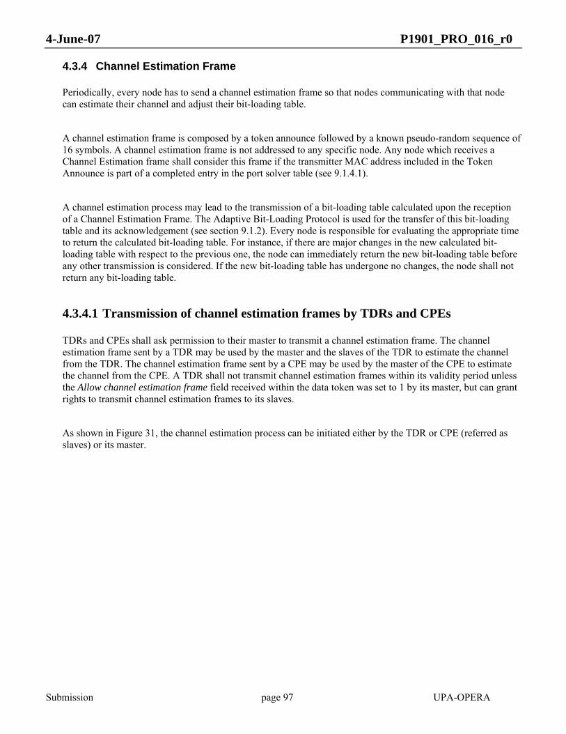
4-June-07 P1901_PRO_016_r0
Submission page 97 UPA-OPERA
4.3.4 Channel Estimation Frame
Periodically, every node has to send a channel estimation frame so that nodes communicating with that node can estimate their channel and adjust their bit-loading table.
A channel estimation frame is composed by a token announce followed by a known pseudo-random sequence of 16 symbols. A channel estimation frame is not addressed to any specific node. Any node which receives a Channel Estimation frame shall consider this frame if the transmitter MAC address included in the Token Announce is part of a completed entry in the port solver table (see 9.1.4.1).
A channel estimation process may lead to the transmission of a bit-loading table calculated upon the reception of a Channel Estimation Frame. The Adaptive Bit-Loading Protocol is used for the transfer of this bit-loading table and its acknowledgement (see section 9.1.2). Every node is responsible for evaluating the appropriate time to return the calculated bit-loading table. For instance, if there are major changes in the new calculated bit-loading table with respect to the previous one, the node can immediately return the new bit-loading table before any other transmission is considered. If the new bit-loading table has undergone no changes, the node shall not return any bit-loading table.
4.3.4.1 Transmission of channel estimation frames by TDRs and CPEs
TDRs and CPEs shall ask permission to their master to transmit a channel estimation frame. The channel estimation frame sent by a TDR may be used by the master and the slaves of the TDR to estimate the channel from the TDR. The channel estimation frame sent by a CPE may be used by the master of the CPE to estimate the channel from the CPE. A TDR shall not transmit channel estimation frames within its validity period unless the Allow channel estimation frame field received within the data token was set to 1 by its master, but can grant rights to transmit channel estimation frames to its slaves.
As shown in Figure 31, the channel estimation process can be initiated either by the TDR or CPE (referred as slaves) or its master.
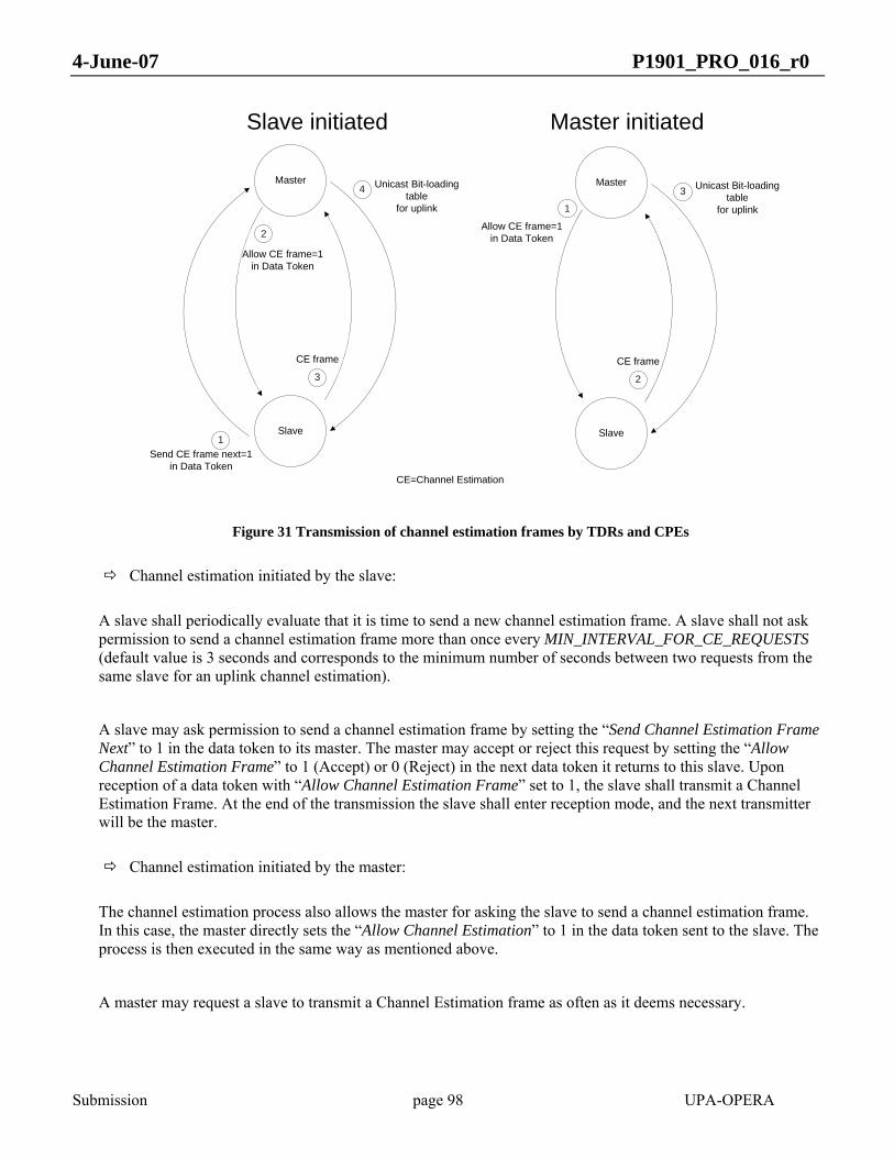
4-June-07 P1901_PRO_016_r0
Submission page 98 UPA-OPERA
Master
Slave1
2
3
4
Send CE frame next=1in Data Token
CE frame
Unicast Bit-loading table
for uplink
Slave initiated
Allow CE frame=1in Data Token
Master initiated
Master
Slave
1
2
3
Allow CE frame=1in Data Token
CE frame
Unicast Bit-loading table
for uplink
CE=Channel Estimation
Figure 31 Transmission of channel estimation frames by TDRs and CPEs
Channel estimation initiated by the slave:
A slave shall periodically evaluate that it is time to send a new channel estimation frame. A slave shall not ask permission to send a channel estimation frame more than once every MIN_INTERVAL_FOR_CE_REQUESTS (default value is 3 seconds and corresponds to the minimum number of seconds between two requests from the same slave for an uplink channel estimation).
A slave may ask permission to send a channel estimation frame by setting the “Send Channel Estimation Frame Next” to 1 in the data token to its master. The master may accept or reject this request by setting the “Allow Channel Estimation Frame” to 1 (Accept) or 0 (Reject) in the next data token it returns to this slave. Upon reception of a data token with “Allow Channel Estimation Frame” set to 1, the slave shall transmit a Channel Estimation Frame. At the end of the transmission the slave shall enter reception mode, and the next transmitter will be the master.
Channel estimation initiated by the master:
The channel estimation process also allows the master for asking the slave to send a channel estimation frame. In this case, the master directly sets the “Allow Channel Estimation” to 1 in the data token sent to the slave. The process is then executed in the same way as mentioned above.
A master may request a slave to transmit a Channel Estimation frame as often as it deems necessary.

4-June-07 P1901_PRO_016_r0
Submission page 99 UPA-OPERA
4.3.4.2 Transmission of channel estimation frames by the HE
The process for the HE is different since it is the only node in the BPL cell that does not have a master.
The HE can send a Channel Estimation Frame as often as it deems necessary. At the end of the transmission of a Channel Estimation frame by the HE, it is the HE which keeps the control of the medium.
The channel estimation frame sent by a HE may be used by the slaves of the HE to estimate the channel from the HE. Each slave will have the opportunity to return the new calculated unicast bit-loading table (via the ABLP protocol) as soon as it receives a data token from its master. However, as described above, the slave shall not necessarily return the unicast bit-loading table as soon as it receives a data token following a Channel Estimation frame.
4.3.5 Polling Frame
As described in 4.2.1, polling frames are used by the master to manage CPE state transitions from Idle to Active or Idle to Unregistered.
Polling frames are frames terminated by a Polling Token. Polling Tokens are addressed to several CPE at the same time via the Polling Destination Bank/Polling Destination Ports fields of the Polling Token (see 4.4.2.4,
Polling Token). A Polling Token is followed by a polling response sequence made of polling slots. The number of polling slots included in this sequence corresponds to the number of bits set to 1 in the Polling Destination Ports field of the polling token (max = 32). First bit set to 1 (going from the Least to the Most Significant bit) corresponds to the first polling slot in the polling response sequence and so forth. Upon reception of a polling
token, a CPE which is addressed by this token shall assert a SOT in its corresponding polling slot if that answer to the polling token is affirmative. It shall not respond if the answer to the polling token is negative.
Figure 32 shows a typical polling scheme in which three CPEs are polled. CPE 1 and CPE 3 assert a SOT in their corresponding polling slots (affirmative response) while CPE 2 does not respond to the polling token (negative response). Polling slots have duration equal to Size Poll Window. Two polling slots are separated by a gap of Offset Poll Window. The last polling slot of the Polling Response Sequence is not followed by this gap: the TX-RX Switch time shall be initiated immediately after the transmission of the last polling slot
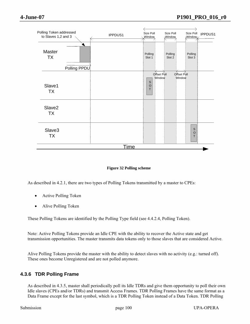
4-June-07 P1901_PRO_016_r0
Submission page 100 UPA-OPERA
Slave1 TX
Master TX
Polling Token addressed to Slaves 1,2 and 3 IPPDUS1
SOT
Polling PPDU
Size Poll Window
Size Poll Window
Size Poll Window
Offset Poll Window
Offset Poll Window
Slave2TX
Slave3TX
Polling Slot 1
Polling Slot 2
Polling Slot 3
SOT
Time
IPPDUS1
Figure 32 Polling scheme
As described in 4.2.1, there are two types of Polling Tokens transmitted by a master to CPEs:
• Active Polling Token
• Alive Polling Token
These Polling Tokens are identified by the Polling Type field (see 4.4.2.4, Polling Token).
Note: Active Polling Tokens provide an Idle CPE with the ability to recover the Active state and get transmission opportunities. The master transmits data tokens only to those slaves that are considered Active.
Alive Polling Tokens provide the master with the ability to detect slaves with no activity (e.g.: turned off). These ones become Unregistered and are not polled anymore.
4.3.6 TDR Polling Frame
As described in 4.3.5, master shall periodically poll its Idle TDRs and give them opportunity to poll their own Idle slaves (CPEs and/or TDRs) and transmit Access Frames. TDR Polling Frames have the same format as a Data Frame except for the last symbol, which is a TDR Polling Token instead of a Data Token. TDR Polling
4-June-07 P1901_PRO_016_r0
Submission page 101 UPA-OPERA
Tokens are addressed to a single port and when they are generated by the master, they shall have enough validity for the polled TDR to transmit Active and Alive Polling Frames, TDR Polling Frames and Access Frames within the maximum intervals.
This kind of frame is also used by the TDR to indicate whether it wants to be Active or stay Idle; in this case this frame can only contain service class 7 traffic, except if it is an Active TDR Polling Reply Frame, case in which any data can be transmitted, according to the remaining validity.
4.3.7 CSMA Frame
The aim of this type of frame is to provide the nodes which do not have access to the channel, an opportunity to gain access. This type of frame is addressed to:
• Idle nodes that have data packets to send in order to change them into active ones.
• Idle nodes that generates bursty traffic
When a node receives a CSMA token and wants to transmit, it must contend for the channel. This contention is performed through a Backoff. If the node wins the contention it starts transmitting; otherwise, the node waits for another CSMA token.
Each node will contend for channel access with a different value depending on its contention priority; contention is prioritized in the following way:-
• High Service class Data traffic and idle state: in order to minimize the probability of collision between nodes that are in the same case each of them will select a random value in the range [P1min, P1max]. In this case, the MAC must configure the node to transmit only packets with service class 7. The idea is to only send the Resource Request Packet and not send the High Service class Data traffic to avoid glitches in the audio or the video application.
• Idle node with control packets: this contention range [P2min, P2max] is reserved in order the idle nodes send the control packets.
• Idle node with Bursty Traffic: this contention range [P3min, P3max] is reserved for nodes with very low throughput of low service class data traffic.

4-June-07 P1901_PRO_016_r0
Submission page 102 UPA-OPERA
P0max P1min
P2max P3min
CONTENTION WINDOW
P1max P2min P3max
CSMA Token
IPPDUS1Backoff
slot time
SOT
CSMA PPDU
Backoff time
P0min
SOT
PPDU
Token
Contention winner Node
Figure 33: Use of CSMA Token to assign channel time to the contention winner node
4.3.8 Access Frame
A master shall periodically transmit Access tokens inviting Unregistered slaves or Registered slaves that want to change masters to subscribe to the network. An Access Token does not have a specific destination, and thus it is possible that no slave will answer to this request. Upon receiving an access frame, an Unregistered slave or a Registered slave that decides to reply must send an access reply frame as described in 4.3.6.
4.3.9 Access Reply Frame
The access reply frame is sent by an Unregistered slave that wishes to enter the network, or a Registered slave that wishes to change its current master. The transmission of an Access Reply Frame is triggered by the reception of an Access Frame.

4-June-07 P1901_PRO_016_r0
Submission page 103 UPA-OPERA
Slave TX
Master TX
Time
Access Token
Access Reply Token
Backoff time: slave selects slot 5
IPPDUS1 Backoff slot time
SOT
SOT
Access Reply PPDU
Access PPDU
Figure 34 Access Reply scheme
The Access Reply Frame is preceded by a contention. The contention method used is the backoff contention method: all contending nodes select a random amount of time to wait before beginning the transmission. The SOT can be transmitted in one of 16 slots. Each node that intends to send an Access Reply PPDU will select a random number between 1 and 16 with a uniform distribution and schedule the transmission of the PPDU in the appropriate slot (slot 1 corresponds to the first slot after the TX-RX switch time has expired). The size of each slot is BACKOFF_SLOT_TIME. After the backoff time has expired, the Access Reply PPDU must be transmitted. If a SOT (beginning of an Access Reply PPDU) is heard before the time has expired, another node has won the contention and the transmission of the access reply frame should be deferred until a new access frame is received. A new random slot will be selected the next time. Particularly, the backoff process is not affected by the loss of a contention, and the process will be carried out in the same manner, except that the random slot will be selected again.
If no SOT is heard before starting the transmission of the own SOT, the whole transmission of the access reply frame will take place. Its structure is identical to a data frame, except for the final token type.
The master, upon receiving an access reply frame, will consider, taking into account Radius, QoS or any other criteria defined, accepting this node as its slave. The response will be sent as an access packet (see 9.1.3.1). If a node that transmitted an Access Reply PPDU does not receive a reply from the master in ACCEPTATION_TO it will begin the process again.

4-June-07 P1901_PRO_016_r0
Submission page 104 UPA-OPERA
4.3.10 Non-returnable Data Frame
The non-returnable data frame is a frame transmitted from a master to many (up to eight) of its slaves (usually TDRs). The non-returnable data token transmitted at the end of the frame indicates which are the destination nodes and for how long they will be allowed to transmit. This length of time is known as the token validity, and is expressed as a number of symbols. The non-returnable data frame can only be sent by a master if Cluster Discovery Protocol (See 0) messages have been received from the TDRs that are slaves to it.
Upon transmitting a non-returnable data token, the master will ignore any signals received until the validity time is finished. At this point, the master will transmit a new frame. No frame will be expected by the transmitter of the non-returnable data frame.
Upon reception of the non-returnable data frame, the slaves (usually TDRs) will start transmitting new frames. However, they must not transmit any data in the upstream (data for the master that sent the non-returnable data frame), or any channel estimation frames.
The non-returnable data frame allows the simultaneous transmission of data and tokens of several isolated clusters, thus allowing for spatial reuse.
4.3.11 Clock Frame
The Clock frame is used to synchronize all nodes of a BPL cell.
Every node shall have an internal timer derived from a 312.5 kHz clock. The periodic timer shall count down from a maximum value to zero. The maximum timer value (Tmax) shall be adapted to span 9 mains periods to allow enough numerical accuracy. This value is transmitted in the Clock token together with the remaining cycles (TimerValue) which shall be the value of the timer in the moment the Clock token is transmitted.
The information transmitted in the Clock frame shall be the remaining cycles for reaching the end of the timer period. This information is used in the receiver node to calculate the delay between its timer and the transmitter timer. The delay with the master shall be used to compensate the own timer. The Clock frame shall be transmitted only from masters to its direct slaves. Therefore, when a node receives a Clock frame, it shall check that it comes from its direct master before using the information. The master/slave tree topology allows the propagation of the information.
The mains frequency is not a stable value and fluctuates depending on the energy demand. So, the maximum timer value shall be continuously corrected to follow the mains variations. Tmax can be obtained in two different ways:
1. Using a zero-cross point detection circuit. 2. Using the MaximumCorrectionValue field of the Clock token. This field allows a slave to synchronize with
the network clock without using a zero-cross point detection circuit.
From Tmax the value of the actual mains periord (Tmains) can be calculated in the following way:

4-June-07 P1901_PRO_016_r0
Submission page 105 UPA-OPERA
9maxT
Tmains =
Equation 33
This periodic timer shall be used to divide the mains period in fixed duration time slots called Qs. The Qs shall be obtained directly from the periodic timer (Ti) as it is shown in Equation 34.
( ) 6mod >>= mainsi TTQ
Equation 34
The duration of a Q is 204.8 μs, and the number of Qs (mains period divisions) will be different depending on the mains frequency. For example 98 in the case of 50 Hz and 82 in the case of 60 Hz, assuming there is no deviation from the nominal frequency.
The MPDU of a Clock frame shall be composed by a Token Announce and a Clock token delimiter. The transmitter of a Clock frame shall know exactly the frame size (in symbols) before start transmitting, in order to calculate the delay added in the transmission of that frame. This delay shall be compensated in the transmitted remaining cycles (TimerValue field of the Clock token).
The Clock frame shall be transmitted every CLOCK_PERIOD_TIME.
The following figures show the described timing references:
0 V
Q @ 60 Hz
Q @ 50 Hz 97
96
95
81
80
79
2 1 0
2 1 0
...
...
3
3
94
78
... 81
80
79
78
50 Hz Mains60 Hz Mains
Figure 35 Qs Vs mains period

4-June-07 P1901_PRO_016_r0
Submission page 106 UPA-OPERA
Figure 36: Clock frame timming reference
4.4 MAC DELIMITERS
As described in 4.3, the MAC layer generates two types of MPDUs: regular MPDUs and Channel Estimation MPDUs. These MPDUs make use of two MAC delimiters:
• Token Announce
• Token
Note: MAC delimiters are processed by the PHY layer as described in 3.3.1.
4.4.1 Token announce
The Token Announce is sent in the initial sequence of every transmission frame. The Token Announce has the following fields:
- Preamble – 32 bits. The preamble is equal to 0x90471D2D. The preamble is used to distinguish the different types of control symbols.
- Type – 4 bits. In this case, Type should be ANNOUNCE(3).
- Validity – 12 bits. Maximum number of symbols that will be transmitted in the current transmission after this Token Announce Symbol. The maximum number that can be used is MAX_TA_VALIDITY
- Access Id – 16 bits. This id must be set to 0x0001.

4-June-07 P1901_PRO_016_r0
Submission page 107 UPA-OPERA
- Channel Estimation Frame – 1 bit. If this frame is a Channel Estimation Frame, Channel Estimation Frame must be set to 1. Otherwise, Channel Estimation Frame must be set to 0.
- Power Control bits – 5 bits. From left to right:
Bit 4. Set to 1 on booting and after the transmission gain is increased. Set to 0 fifteen seconds after it was set to 1.
Bit 3. Set to 1 if the node cannot decrease its transmission gain due to own reasons. For example: low throughput. Set to 0 otherwise.
Bit 2. Set to 1 if the node is not going to decrease its transmission gain due to other nodes reasons, but if those external circumstances end then the transmission gain could be decreased (depending on bit 3). For example: when another equipment has bit 3 to 1 and the node wants to isolate from it. Set to 0 otherwise.
Bit 1. Set to 1 if the power control task is on. Set to 0 otherwise.
Bit 0. Set to 1 if transmission gain has been decreased and isolation is expected. Set to 0 if transmission gain has its maximum (initial) value.
If power control is not implemented this field shall be set to 0b01000
- MAC Mode – 3 bits. Must be set to 0b001 for Access.
- Type of Node – 3 bits. See below
- ACCRQ – 1 bit. If this frame is an Access Frame, ACCRQ must be set to 1. Otherwise, ACCRQ must be set to 0. Using this field, a node that is searching for a master only needs to receive the TA to know that it is an Access frame.
- MID – 21 bits. Master Id. It is used to detect if there is interference from other BPL cell. The problem of interference appears when there is more than one node allocating the channel in time. This can happen when there are two BPL cells, each one having its own HE, and the transmissions from some nodes in one of them can be received by some nodes in the other BPL cell.
The first problem is to know if a node is being interfered because there is more than one HE in the channel. To solve this issue all the nodes that share the token must identify themselves as members of the same BPL cell.
The HE of the BPL cell must transmit an identifier, so called Master Id [MID], and each node that depends directly or indirectly (because is in the HE’s BPL cell) must copy the MID.
The transmission of the MID is splitted between 2 symbols, the Token Announce and the Access or CSMA Token
In the Token Announce, 21 bits are sent, with the following structure:
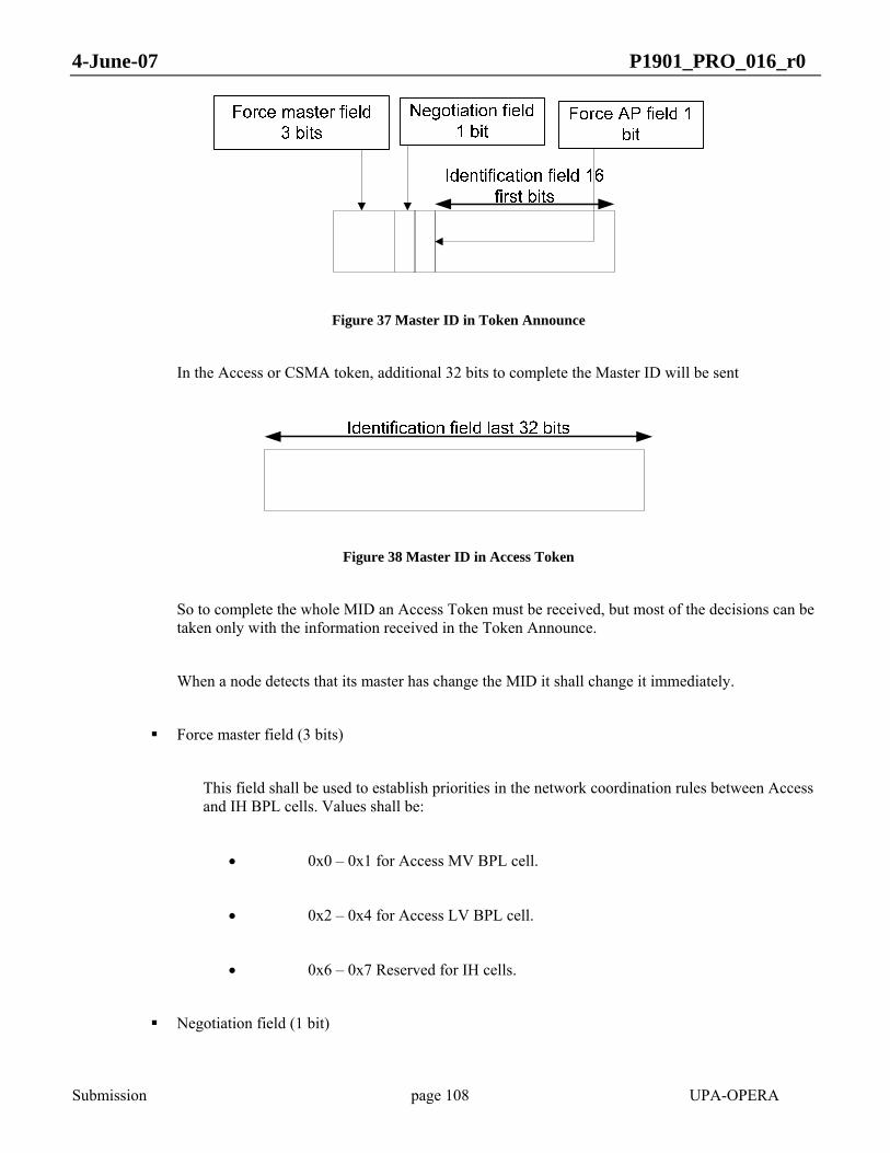
4-June-07 P1901_PRO_016_r0
Submission page 108 UPA-OPERA
Figure 37 Master ID in Token Announce
In the Access or CSMA token, additional 32 bits to complete the Master ID will be sent
Figure 38 Master ID in Access Token
So to complete the whole MID an Access Token must be received, but most of the decisions can be taken only with the information received in the Token Announce.
When a node detects that its master has change the MID it shall change it immediately.
Force master field (3 bits)
This field shall be used to establish priorities in the network coordination rules between Access and IH BPL cells. Values shall be:
• 0x0 – 0x1 for Access MV BPL cell.
• 0x2 – 0x4 for Access LV BPL cell.
• 0x6 – 0x7 Reserved for IH cells.
Negotiation field (1 bit)

4-June-07 P1901_PRO_016_r0
Submission page 109 UPA-OPERA
It is used to change the priority of a MID in the coordination rules depending on the scenarios. Default value shall be 1. The following rules shall be respected:
• A node with the same MID except for the Negotiation field shall consider it as the same MID. In this case, the Negotiation field shall not be considered in the network coordination rules.
• A node with different MID (Force Master, Reserved field or Identification field) shall consider the Negotiation field in the network coordination rules.
The next 2 rules assert that the Negotiation field will be set to the same value into the same BPL cell if a change is made by a single node:
• If the Negotiation field changes from 1 to 0 in a node, its master shall set the Negotiation field to 0.
• If the Negotiation field changes in a node, its slaves shall set the same Negotiation field value.
Only the HE can change the Negotiation field from 0 to 1 again. The HE shall change the Negotiation field from 0 to 1 after 120 seconds from the change from 1 to 0.
Reserved field (1 bit)
For future use.
Identification field (48 bits)
By default it should be the Mac Address of the HE stored in reverse order. It shall not be assumed by any protocol that the MasterId includes a MAC address.
For example, the MAC 0x00139D0002A8 will produce the Identification Field 0xA802009D1300
- MAC – 48 bits. This is the MAC address of transmitter.

4-June-07 P1901_PRO_016_r0
Submission page 110 UPA-OPERA
90
01234567
47
1D
2D
Type Validity [11:8]
Validity [7:0]
Always MUST be set to 0
Ch. Est. Fr.
MAC ModeAlways MUST be set to 0
Always MUST be set to 0
MID [15:8]
MID [7:0]
Access Id [7:0]
Access Id [15:8]
Always MUST be set to 0
MAC[1]
MAC[2]
MAC[3]
MAC[4]
preamble
MAC[0]
MAC[5]
Always MUST be set to 0
TypeOfNode[2]
Type of Node [1:0] MID [20:16] ACCRQ
Power Control bits Always MUST be set to 0
Figure 39 Token Announce
The field Type has the following meanings:
3 ANNOUNCE
The field Type of Node has the following meanings:
0 HE
1 CPE
2 TDR

4-June-07 P1901_PRO_016_r0
Submission page 111 UPA-OPERA
4.4.2 Token
There are ten kinds of Token:
- Distributor Token
- Data Token
- Silence Token
- Polling Token
- TDR Polling Token
- CSMA Token
- Access Token
- Access Reply Token
- Non-returnable Data Token
- Clock Token
The field Type has the following meanings:
Token Type Value
DATA 0
NON-RETURNABLE 2
CLOCK 3
POLLING 5
TDR POLLING 7
DISTRIBUTOR TOKEN 8
CSMA 9
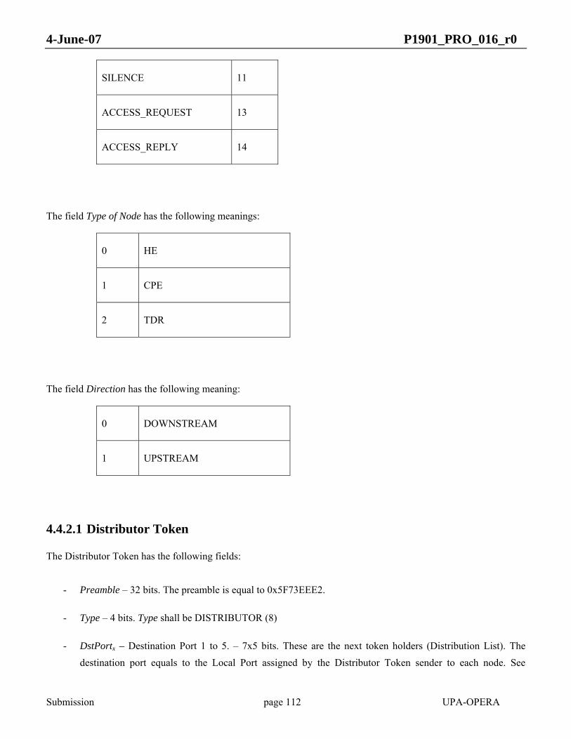
4-June-07 P1901_PRO_016_r0
Submission page 112 UPA-OPERA
SILENCE 11
ACCESS_REQUEST 13
ACCESS_REPLY 14
The field Type of Node has the following meanings:
0 HE
1 CPE
2 TDR
The field Direction has the following meaning:
0 DOWNSTREAM
1 UPSTREAM
4.4.2.1 Distributor Token
The Distributor Token has the following fields:
- Preamble – 32 bits. The preamble is equal to 0x5F73EEE2.
- Type – 4 bits. Type shall be DISTRIBUTOR (8)
- DstPortx – Destination Port 1 to 5. – 7x5 bits. These are the next token holders (Distribution List). The destination port equals to the Local Port assigned by the Distributor Token sender to each node. See
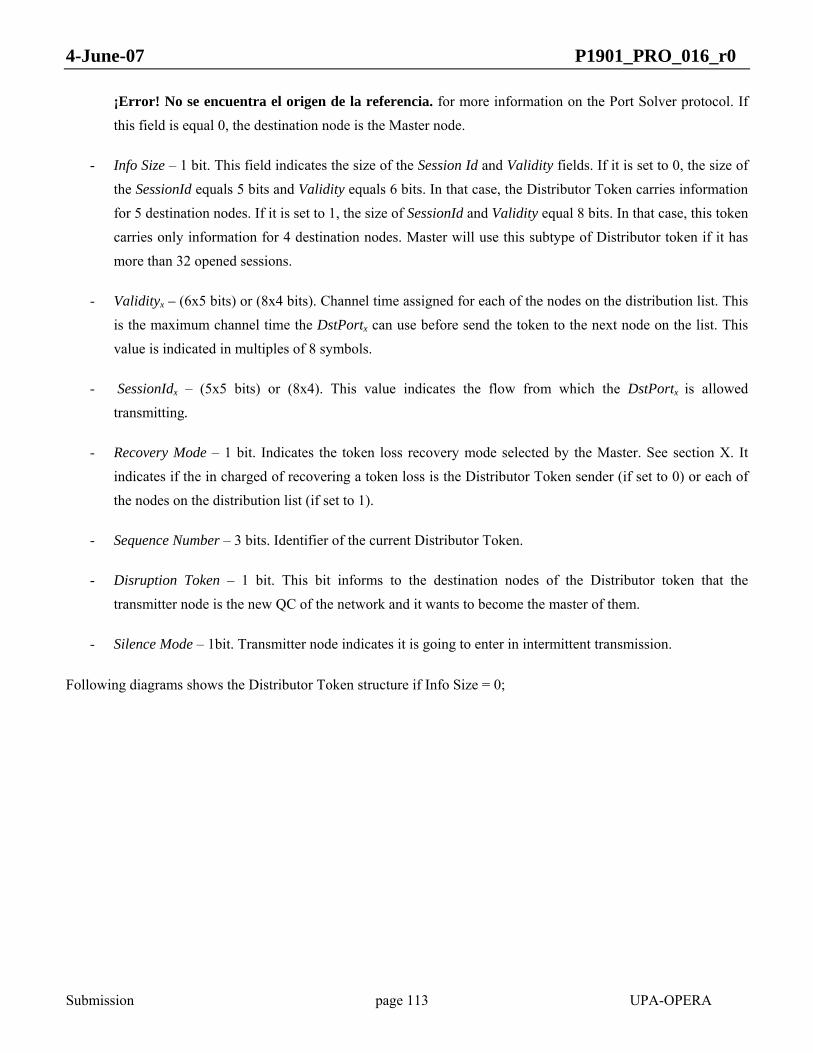
4-June-07 P1901_PRO_016_r0
Submission page 113 UPA-OPERA
¡Error! No se encuentra el origen de la referencia. for more information on the Port Solver protocol. If this field is equal 0, the destination node is the Master node.
- Info Size – 1 bit. This field indicates the size of the Session Id and Validity fields. If it is set to 0, the size of the SessionId equals 5 bits and Validity equals 6 bits. In that case, the Distributor Token carries information for 5 destination nodes. If it is set to 1, the size of SessionId and Validity equal 8 bits. In that case, this token carries only information for 4 destination nodes. Master will use this subtype of Distributor token if it has more than 32 opened sessions.
- Validityx – (6x5 bits) or (8x4 bits). Channel time assigned for each of the nodes on the distribution list. This is the maximum channel time the DstPortx can use before send the token to the next node on the list. This value is indicated in multiples of 8 symbols.
- SessionIdx – (5x5 bits) or (8x4). This value indicates the flow from which the DstPortx is allowed transmitting.
- Recovery Mode – 1 bit. Indicates the token loss recovery mode selected by the Master. See section X. It indicates if the in charged of recovering a token loss is the Distributor Token sender (if set to 0) or each of the nodes on the distribution list (if set to 1).
- Sequence Number – 3 bits. Identifier of the current Distributor Token.
- Disruption Token – 1 bit. This bit informs to the destination nodes of the Distributor token that the transmitter node is the new QC of the network and it wants to become the master of them.
- Silence Mode – 1bit. Transmitter node indicates it is going to enter in intermittent transmission.
Following diagrams shows the Distributor Token structure if Info Size = 0;

4-June-07 P1901_PRO_016_r0
Submission page 114 UPA-OPERA
Figure 40 Distributor Token Info Size = 0
Following diagrams shows the Distributor Token structure if Info Size = 1;

4-June-07 P1901_PRO_016_r0
Submission page 115 UPA-OPERA
Figure 41 Distributor Token Info Size = 0
4.4.2.2 Data token
The Data Token has the following fields:
- Preamble – 32 bits. The preamble is equal to 0x5F73EEE2.
- Type – 4 bits. Type shall be DATA (0)
- Direction – 1 bit. See above.
- Transmission in HURTO – 1 bit. Indicates whether the transmission from Token Transmitter to Destination Port is using HURTO or not.
- Allow Channel Estimation Frame– 1 bit. From Master to Slave. If it is set to 1, the Slave receiving this token must send a Channel Estimation Frame. See 4.3.3 for more information.
- Send Channel Estimation Frame next – 1 bit. From Slave to Master. The Slave is requesting to send a Channel Estimation Frame. See 4.3.3 for more information.

4-June-07 P1901_PRO_016_r0
Submission page 116 UPA-OPERA
- Single Validity – 4 bits. It is expressed in slots (each slot is composed of 16 symbols). The Single Validity is an indication from the master on the validity that may be assigned for individual transmission. This information is only used as an example of how to distribute the token validity. However, the receiving node does not have to follow that distribution. In that case the receiving node may change the Single Validity to a new value, according to the validity that it assigns in the Data Token. Individual transmission means the transmission from a TDR to a CPE or a CPE to its TDR. This field is not used by CPEs. The relevant field for CPEs is the Validity. The Single Validity includes all symbols transmitted after the TA. The minimum Single Validity is 1.
- Validity – 12 bits. From Master to Slave. This indicates the maximum validity that the slave will be allowed to use before returning the token. It is expressed as a number of symbols. The master shall start a timer after the transmission of the Token Announce by the slave with the duration of the Validity it has assigned, and expect to receive the token back before this timer expires. If the slave is a repeater, the Validity includes the time needed for the repeater to communicate with its slaves.
- Destination Port – 7 bits. Local Port assigned to the intended receiver of the Data Token. See 9.1.4 for more information on the Port Solver protocol.
- Session Id – 8 bits. Identify a specific flow reserved by the CAC protocol that should have priority over other flows registered or best-effort traffic.
- Frame Service class – 8 bits. Only used from slave to master. The Frame Service class field in the token is used to convey the information of the service classes that have been transmitted within the frame, when the token is directed towards its master node and also all the service classes detected in the previous upstream transmissios. CPEs use this field to indicate the service classes sent in their transmission and TDRs gather the service class information of their slaves and the service class information from their own transmissions. Therefore, the HE has the information of all the priorities transmitted in the network. When the token is transmitted towards slave nodes, this field is not used. If bit X is equal to 1, there is at least one packet in this frame with service class X.
- Unused frame symbols - 13 bits. Unused symbols in the current frame, compared to the Validity indicated in the token announce of the same transmission frame.
- Received words - 16 bits. The Received Words Field is used to communicate to the token receiver the number of 32-bit words that have been received from that destination since the last time, so that the bandwidth limitation algorithm can respond. Counting shall be performed over complete received packets when they are passed to the Convergence Layer.
- Number of Downstream Nodes – 8 bits From a CPE to its master, the Number of Downstream Nodes is equal to 0. From a TDR to its master, the Number of Downstream Nodes is equal to the number of nodes in its BPL subtree minus 1.
- Maximum Number of Hops – 4 bits. From a CPE to its master, the Maximum Number of Hops is equal to 0. A TDR will set the Maximum Number of Hops as the maximum value of number of hops amongst those received by the nodes hanging from it plus 1.When this field is set to 31 means that there are 32 hops or more.
- Distributor Sequence Number – 3 bits. Identifier of the current Distributor Token when this Data Token belongs to an scheduded chain of transmissions generated by a Distributor Token.

4-June-07 P1901_PRO_016_r0
Submission page 117 UPA-OPERA
5F
01234567
73
EE
E2
Type
Validity [11:8]
Validity [7:0]
Destination Port
Frame Priority
Session ID [7:0]
Always MUST be set to 0
Received words [7:0]
Unused Frame Symbols [12:8]
Unused Frame Symbols [7:0]
Reserved
Single Validity
Received words [15:8]
Number of Downstream Nodes
Reserved
Maximum Number of Hops
Always MUST be set to 0
preamble
Direction ReservedTransmission
in HURTOAlow Channel Estimation Fr.
Send Ch. Est. Fr. Next
Always MUST be set to 0
Always MUST be set to 0
Reserved
Reserved
Distributor Sequence Number Always MUST be set to 0 No Destination Port Always MUST be set to 0
Figure 42 Data Token
4.4.2.3 Silence Token
The Silence Token includes the following fields of the data token:
- Preamble – 32 bits. The preamble is equal to 0x5F73EEE2.
- Type – 4 bits. Type shall be SILENCE (11).
- Unused frame symbols (13 bits). Unused symbols in the current frame, compared to the Validity indicated in the token announce of the same transmission frame.

4-June-07 P1901_PRO_016_r0
Submission page 118 UPA-OPERA
5F
01234567
73
EE
E2
Type
Always MUST be set to 0
Always MUST be set to 0
Unused Frame Symbols [12:8]
Unused Frame Symbols [7:0]
Always MUST be set to 0
preamble
Always MUST be set to 0
Always MUST be set to 0
Always MUST be set to 0
Always MUST be set to 0
Always MUST be set to 0
Always MUST be set to 0
Always MUST be set to 0
Always MUST be set to 0
Always MUST be set to 0
Always MUST be set to 0
Always MUST be set to 0
Always MUST be set to 0
Always MUST be set to 0
Always MUST be set to 0
Figure 43 Silence Token
4.4.2.4 Polling Token
The Polling Token has the following fields:
- Preamble – 32 bits. The preamble is equal to 0x5F73EEE2.
- Type – 4 bits. In this case, Type shall be POLLING (5).
- Polling Type – 1 bit. (The Polling Type could be equal to ACTIVE(1) or ALIVE(0). When Polling Type is ACTIVE, the Polling Token is requesting which nodes have data to be sent. When Polling Type is ALIVE, the Polling Token is requesting which nodes are alive.
- Polling Destination Bank – 2 bits. The total number of destination ports of this Polling Token is divided into 4 banks. The Polling Destination Bank is to know the destination bank of this polling. The first available port is port 9.
0 9 - 40 ports
1 41 - 72 ports
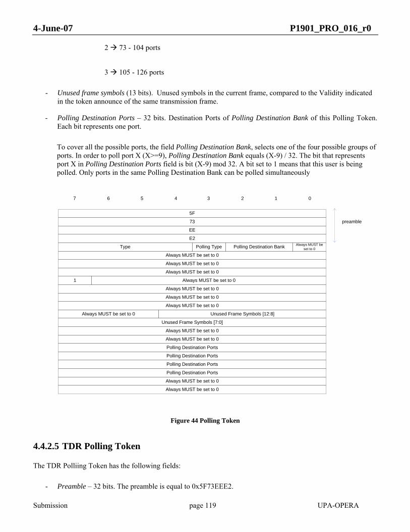
4-June-07 P1901_PRO_016_r0
Submission page 119 UPA-OPERA
2 73 - 104 ports
3 105 - 126 ports
- Unused frame symbols (13 bits). Unused symbols in the current frame, compared to the Validity indicated in the token announce of the same transmission frame.
- Polling Destination Ports – 32 bits. Destination Ports of Polling Destination Bank of this Polling Token. Each bit represents one port.
To cover all the possible ports, the field Polling Destination Bank, selects one of the four possible groups of ports. In order to poll port X (X>=9), Polling Destination Bank equals (X-9) / 32. The bit that represents port X in Polling Destination Ports field is bit (X-9) mod 32. A bit set to 1 means that this user is being polled. Only ports in the same Polling Destination Bank can be polled simultaneously
5F
01234567
73
EE
E2
Type
Always MUST be set to 0
1
Always MUST be set to 0
Always MUST be set to 0
Always MUST be set to 0
Always MUST be set to 0
Unused Frame Symbols [7:0]
Always MUST be set to 0
Always MUST be set to 0
Polling Destination Ports
Polling Destination Ports
Polling Destination Ports
Always MUST be set to 0
preamble
Polling Type
Polling Destination Ports
Always MUST be set to 0
Always MUST be set to 0
Always MUST be set to 0
Polling Destination Bank Always MUST be set to 0
Always MUST be set to 0
Unused Frame Symbols [12:8]
Figure 44 Polling Token
4.4.2.5 TDR Polling Token
The TDR Polliing Token has the following fields:
- Preamble – 32 bits. The preamble is equal to 0x5F73EEE2.

4-June-07 P1901_PRO_016_r0
Submission page 120 UPA-OPERA
- Type – 4 bits. Type shall be TDR POLLING (7)
- Direction – 1 bit. DOWNSTREAM (0) means that this TDR Polling Token is sent by a master to poll a TDR. UPSTREAM (1) means that it is a TDR Polling Reply Token, sent by a TDR to its master.
- Reply – 1 bit. If Reply is ACTIVE (1), the TDR indicates that it wants to be Active and receive transmission opportunities. If it is IDLE (0), the TDR stays as Idle.
- Single Validity – 4 bits. It is expressed in slots (each slot is composed of 16 symbols). The Single Validity is an indication from the master on the validity that may be assigned for individual transmission. This information is only used as an example of how to distribute the token validity. However, the receiving node does not have to follow that distribution. In that case the receiving node may change the Single Validity to a new value, according to the validity that it assigns in the Data Token. Individual transmission means the transmission from a TDR to a CPE or a CPE to its TDR. The Single Validity includes all symbols transmitted after the TA. The minimum Single Validity is 1.
- Validity – 12 bits. From Master to Slave. This indicates the maximum validity that the TDR will be allowed to use before returning the token. It is expressed as a number of symbols. The master shall start a timer after the transmission of the Token Announce by the slave with the duration of the Validity it has assigned, and expect to receive the token back before this timer expires.
- Destination Port – 7 bits. Local Port assigned to the intended receiver of the Data Token. See 9.1.4 for more information on the Port Solver protocol.
- Unused frame symbols – 13 bits. Unused symbols in the current frame, compared to the Validity indicated in the token announce of the same transmission frame.
- Number of Downstream Nodes – 8 bits From a TDR to its master, the Number of Downstream Nodes is equal to the number of nodes in its BPL subtree minus 1 (0 if it has no slaves).
- Maximum Number of Hops – 4 bits. A TDR will set the Maximum Number of Hops as the maximum value of number of hops amongst those received by the nodes hanging from it plus 1 (0 if it has no slaves). When this field is set to 31 means that there are 32 hops or more.
5F
01234567
73
EE
E2
Type
Reserved
Always MUST be set to 0
Always MUST be set to 0
Always MUST be set to 0
Always MUST be set to 0
Unused Frame Symbols [7:0]
Validity[7:0]
Always MUST be set to 0
Number of Downstreams Nodes
Always MUST be set to 0
preamble
Direction
Always MUST be set to 0
Always MUST be set to 0
Always MUST be set to 0
Destination Port
Unused Frame Symbols [12:8]
Reply
Single Validity Validity[11:8]
Always MUST be set to 0 Maximum number of Hops
Always MUST be set to 0
Always MUST be set to 0
Always MUST be set to 0
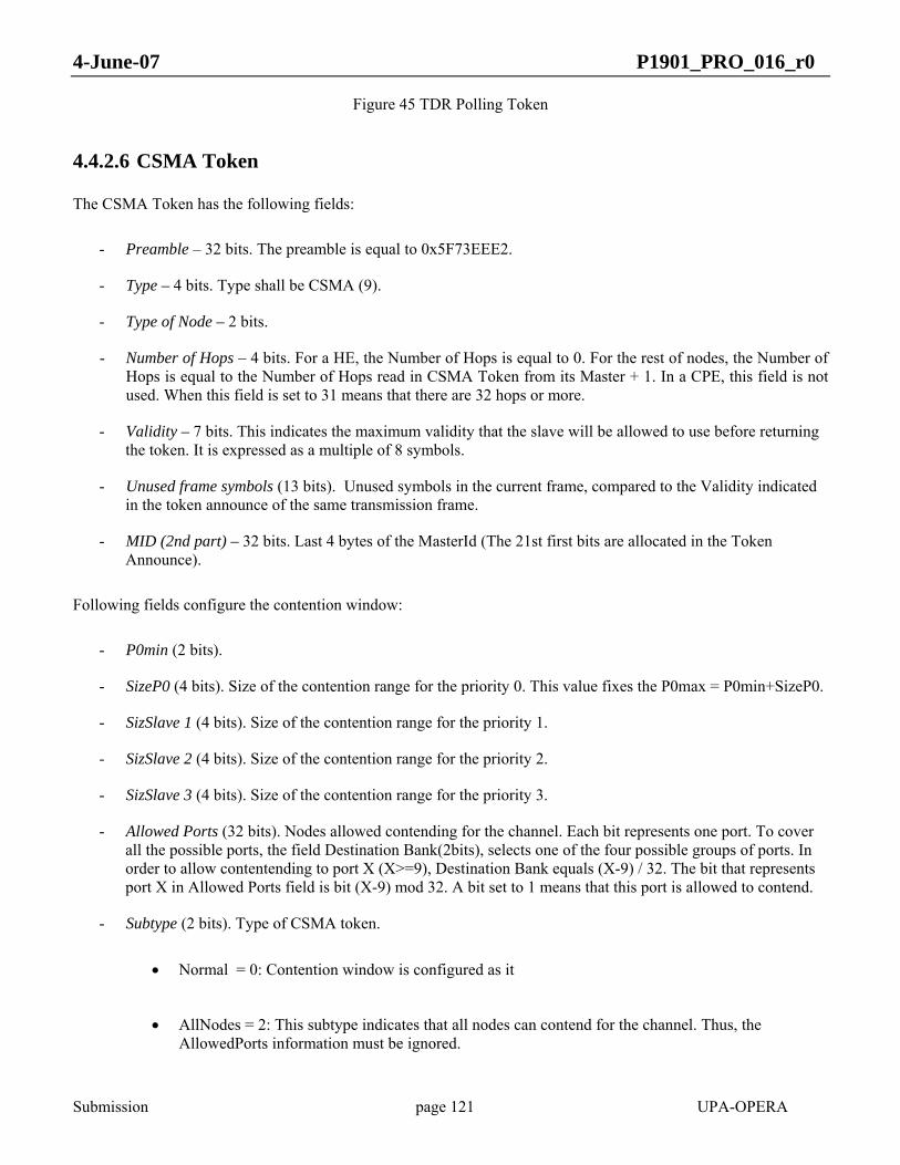
4-June-07 P1901_PRO_016_r0
Submission page 121 UPA-OPERA
Figure 45 TDR Polling Token
4.4.2.6 CSMA Token
The CSMA Token has the following fields:
- Preamble – 32 bits. The preamble is equal to 0x5F73EEE2.
- Type – 4 bits. Type shall be CSMA (9).
- Type of Node – 2 bits.
- Number of Hops – 4 bits. For a HE, the Number of Hops is equal to 0. For the rest of nodes, the Number of Hops is equal to the Number of Hops read in CSMA Token from its Master + 1. In a CPE, this field is not used. When this field is set to 31 means that there are 32 hops or more.
- Validity – 7 bits. This indicates the maximum validity that the slave will be allowed to use before returning the token. It is expressed as a multiple of 8 symbols.
- Unused frame symbols (13 bits). Unused symbols in the current frame, compared to the Validity indicated in the token announce of the same transmission frame.
- MID (2nd part) – 32 bits. Last 4 bytes of the MasterId (The 21st first bits are allocated in the Token Announce).
Following fields configure the contention window:
- P0min (2 bits).
- SizeP0 (4 bits). Size of the contention range for the priority 0. This value fixes the P0max = P0min+SizeP0.
- SizSlave 1 (4 bits). Size of the contention range for the priority 1.
- SizSlave 2 (4 bits). Size of the contention range for the priority 2.
- SizSlave 3 (4 bits). Size of the contention range for the priority 3.
- Allowed Ports (32 bits). Nodes allowed contending for the channel. Each bit represents one port. To cover all the possible ports, the field Destination Bank(2bits), selects one of the four possible groups of ports. In order to allow contentending to port X (X>=9), Destination Bank equals (X-9) / 32. The bit that represents port X in Allowed Ports field is bit (X-9) mod 32. A bit set to 1 means that this port is allowed to contend.
- Subtype (2 bits). Type of CSMA token.
• Normal = 0: Contention window is configured as it
• AllNodes = 2: This subtype indicates that all nodes can contend for the channel. Thus, the AllowedPorts information must be ignored.
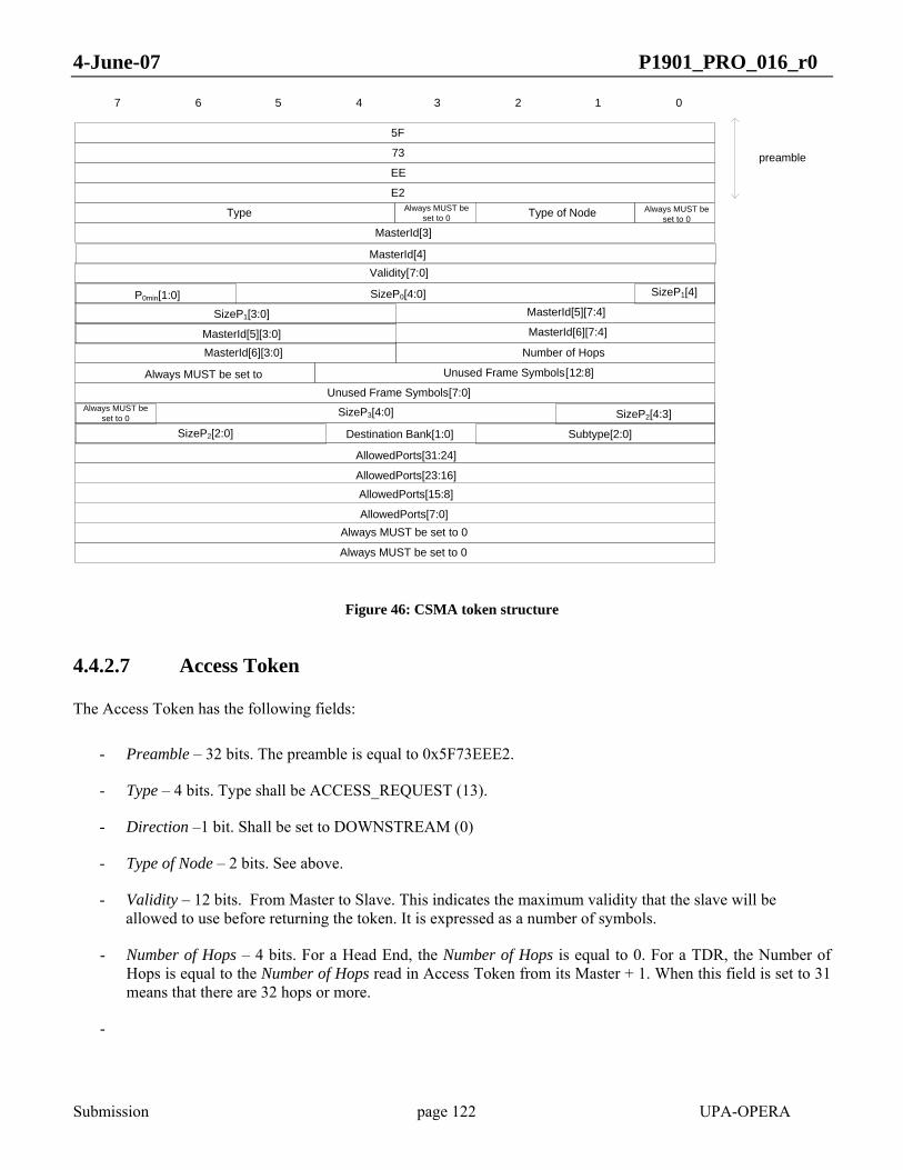
4-June-07 P1901_PRO_016_r0
Submission page 122 UPA-OPERA
5F
01234567
73
EE
E2
Type
Validity [7:0]
P0min[1:0]MasterId[5][7:4]
MasterId[6][7:4]
Number of Hops
Unused Frame Symbols [12:8]
Unused Frame Symbols [7:0]
MasterId[3]
preamble
Type of Node
Always MUST be set to 0
Always MUST be set to 0
MasterId[6][3:0]
Always MUST be set to
Always MUST be set to 0
MasterId[4]
SizeP0[4:0] SizeP1[4]
SizeP1[3:0]
MasterId[5][3:0]
SizeP3[4:0]Always MUST be set to 0 SizeP2[4:3]
SizeP2[2:0] Destination Bank[1:0] Subtype[2:0]
AllowedPorts[31:24]
AllowedPorts[23:16]AllowedPorts[15:8]
AllowedPorts[7:0]Always MUST be set to 0
Figure 46: CSMA token structure
4.4.2.7 Access Token
The Access Token has the following fields:
- Preamble – 32 bits. The preamble is equal to 0x5F73EEE2.
- Type – 4 bits. Type shall be ACCESS_REQUEST (13).
- Direction –1 bit. Shall be set to DOWNSTREAM (0)
- Type of Node – 2 bits. See above.
- Validity – 12 bits. From Master to Slave. This indicates the maximum validity that the slave will be allowed to use before returning the token. It is expressed as a number of symbols.
- Number of Hops – 4 bits. For a Head End, the Number of Hops is equal to 0. For a TDR, the Number of Hops is equal to the Number of Hops read in Access Token from its Master + 1. When this field is set to 31 means that there are 32 hops or more.
-

4-June-07 P1901_PRO_016_r0
Submission page 123 UPA-OPERA
- Unused frame symbols (13 bits). Unused symbols in the current frame, compared to the Validity indicated in the token announce of the same transmission frame.
- MID (2nd part) – 32 bits. Last 4 bytes of the MasterId (The 21st first bits are allocated in the Token Announce).
- MAC Address – 48 bits. Own MAC address.
- Equivalent speed – 8 bits. This value gives an indication of the throughput to the backbone that can be achieved connecting to the network through this node. The value is calculated from the equivalent BPS.
⎥⎦
⎥⎢⎣
⎢ −=
60120
_ eqBPSspeedEquivalent
Equation 35
If the node is directly linked to the backbone the field will be set to 255. If the node is one hop from the backbone the equivalent BPS are equal to the average of the downstream and upstream BPS of the node with its master.
owneq
downupeq BPS
BPSBPSBPS =
+=
2
Equation 36
If there is more than one hop to the backbone the equivalent BPS are calculated from the BPS value obtained from the master and the own equivalent BPS.
owneq
ieq
ieq
BPSBPS
BPS 111
1 +=
−
Equation 37
Values for the equivalent speed obtained from the previous formulas shall be between 1 and 254. A value of zero in this field means that the repeater has not been able to calculate it. The BPS information obtained from the access token, combined with the BPS calculated by the new slave in the link may be used in order to decide which is the best master to be connected to.

4-June-07 P1901_PRO_016_r0
Submission page 124 UPA-OPERA
5F
01234567
73
EE
E2
Type
Validity [7:0]
Number of Hops
MAC [1]
Unused Frame Symbols [12:8]
Unused Frame Symbols [7:0]
Always MUST be set to 0
Validity [11:8]
MAC [0]
MAC [3]
MAC [4]
MAC [5]
Equivalent Speed
preamble
Direction Type of Node
MAC [2]
Always MUST be set to 0
Always MUST be set to 0
MasterId[3][7:4]
Always MUST be set to 0
MasterId[6][3:0]
MasterId[5][3:0]
MasterId[4][3:0]
MasterId[3][3:0]
MasterId[6][7:4]
MasterId[5][7:4]
MasterId[4][7:4]
Figure 47 Access Token
4.4.2.8 Access Reply Token
The Access Token has the following fields:
- Preamble – 32 bits. The preamble is equal to 0x5F73EEE2.
- Type – 4 bits. Type shall be ACCESS_REPLY (14).
- Direction –1 bit. Shall be set to UPSTREAM (1).
- Type of Node – 2 bits. See above.
- MID – 32 bits. Part of the Master ID not included in the Token Announce.
- Disconnect – 1bit. If this field is set to 0, the token is a normal ACCESS REPLY TOKEN, used to achieve access to the network through a master. If it is set to 1, the token becomes an ACCESS REPLY DISCONNECTION TOKEN, used to leave a master.
- Destination Port – 7 bits. Local Port assigned to the master.

4-June-07 P1901_PRO_016_r0
Submission page 125 UPA-OPERA
- Number of Hops – 4 bits. For a Head End, the Number of Hops is equal to 0. For a TDR, the Number of Hops is equal to the Number of Hops read in Access Token from its Master + 1. In a CPE, this field is not used. When this field is set to 31 means that there are 32 hops or more.
- Unused frame symbols (13 bits). Unused symbols in the current frame, compared to the Validity indicated in the token announce of the same transmission frame.
- MAC Address – 48 bits. The MAC address of the master the access reply token is addressed to.
Figure 48 Access Reply Token
4.4.2.9 Non-returnable data token
The Non-returnable Data Token has the following fields:
- Preamble – 32 bits. The preamble is equal to 0x5F73EEE2.
- Type – 4 bits. Type shall be NON-RETURNABLE (2)
- Single Validity – 4 bits. See description in 0
- Validity – 12 bits. Same meaning as in the Data Token (See 0). Since this token is non-returnable, the validity will be fully used.
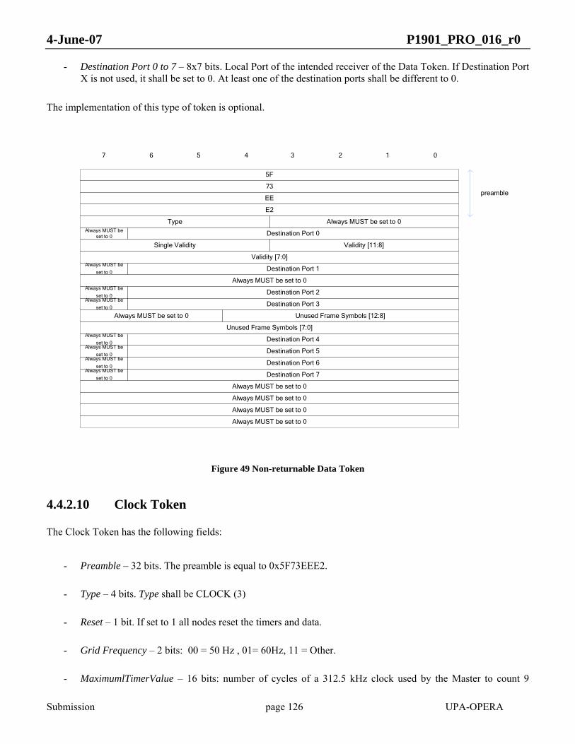
4-June-07 P1901_PRO_016_r0
Submission page 126 UPA-OPERA
- Destination Port 0 to 7 – 8x7 bits. Local Port of the intended receiver of the Data Token. If Destination Port X is not used, it shall be set to 0. At least one of the destination ports shall be different to 0.
The implementation of this type of token is optional.
5F
01234567
73
EE
E2
Type
Validity [11:8]
Validity [7:0]
Destination Port 2
Always MUST be set to 0
Single Validity
Destination Port 7
Destination Port 6
Always MUST be set to 0
preamble
Always MUST be set to 0
Always MUST be
set to 0
Always MUST be set to 0
Destination Port 3
Destination Port 1
Always MUST be set to 0
Always MUST be set to 0
Always MUST be
set to 0
Always MUST be
set to 0Always MUST be
set to 0
Always MUST be set to 0
Destination Port 4
Destination Port 5
Always MUST be
set to 0Always MUST be
set to 0
Unused Frame Symbols [7:0]
Destination Port 0Always MUST be set to 0
Always MUST be
set to 0
Unused Frame Symbols [12:8]
Figure 49 Non-returnable Data Token
4.4.2.10 Clock Token
The Clock Token has the following fields:
- Preamble – 32 bits. The preamble is equal to 0x5F73EEE2.
- Type – 4 bits. Type shall be CLOCK (3)
- Reset – 1 bit. If set to 1 all nodes reset the timers and data.
- Grid Frequency – 2 bits: 00 = 50 Hz , 01= 60Hz, 11 = Other.
- MaximumlTimerValue – 16 bits: number of cycles of a 312.5 kHz clock used by the Master to count 9
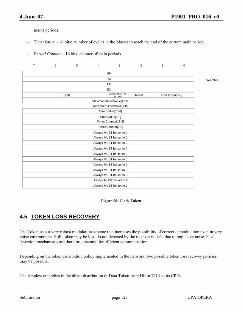
4-June-07 P1901_PRO_016_r0
Submission page 127 UPA-OPERA
mains periods.
- TimerValue - 16 bits: number of cycles in the Master to reach the end of the current main period.
- Period Counter – 16 bits: counter of main periods.
5F
01234567
73
EE
E2
Type
preamble
Always MUST be set to 0
Always MUST be set to 0
Always MUST be set to 0
Always MUST be set to 0
Always MUST be set to 0
Always MUST be set to 0
Always MUST be set to 0
Always MUST be set to 0
Always MUST be set to 0Always MUST be set to 0
Reset Grid Frequency
MaximumTimerValue[15:8]
TimerValue[15:8]
TimerValue[7:0]PeriodCounter[15:8]
PeriodCounter[7:0]
Always MUST be set to 0
Always MUST be set to 0
MaximumTimerValue[7:0]
Figure 50: Clock Token
4.5 TOKEN LOSS RECOVERY
The Token uses a very robust modulation scheme that increases the possibility of correct demodulation even in very noise environment. Still, token may be lost, do not detected by the receiver node/s, due to impulsive noise. Fast detection mechanisms are therefore essential for efficient communication.
Depending on the token distribution policy implemented in the network, two possible token loss recovey policies may be possible.
The simplest one relies in the direct distribution of Data Token from HE or TDR to its CPEs.

4-June-07 P1901_PRO_016_r0
Submission page 128 UPA-OPERA
In this case, a token loss occurs when the master node transmits a frame and the intended token receiver does not detect the token or when the master does not detect the token sent by one of its slaves. In case of token loss, the master node shall detect that the token has been lost.
Using the validity associated to every transmitted token, the master node shall generate a new frame whenever the validity assigned in a token to one of its slaves expires without receiving back the token. Only HE and TDR implement this feature.
When a Token Distributor is used to share the channel, the Token Loss Recovery policy becomes more complex, but equally efficient.
There are two different modes to recover a token lost when using Distributor Tokens:
1. Master node is the only node in charged of recovering a token lost. In this mode, the node that sends the Distributor token must monitor the channel during all the validity time assigned in the token in order to detect in each moment if the channel owner transmits.
When Master transmits a Distributor Token checks that the first node on the distribution list starts transmitting. If Master does not detect the Token Announce from the expected node, it can retransmit the Distributor Token lost or a new Distributor Token. In that way, the only overhead included in this simple acknowledgement mechanism is the retransmission of the token, instead of waiting for the maximum time assigned to the first slave.
If first slave detects the Distributor Token, it starts transmitting and assigns the channel to the second destination slave. This process will be monitorized by the Master. If Master node detects the first slave assigns the channel to the next slave, it will check if the second slave starts transmitting. If Master does not detect the Token Announce from that slave, it transmits a new Distributor Token. This Distributor Token can include the slave that lost the token or can continue in the next slave on the distribution list.
Master shall repeat all this process till the last destination slave returns the channel to the Master.
Master node shall know in each moment which is the channel owner slave, when it has to start transmitting, and when it has to release the token to the next slave.
Following diagram shows the monitoring process performed by the Master in order to recover a token lost:

4-June-07 P1901_PRO_016_r0
Submission page 129 UPA-OPERA
Figure 51: Distributor Token Lost Monitoring Process

4-June-07 P1901_PRO_016_r0
Submission page 130 UPA-OPERA
DISTRIBUTORTOKEN
MASTER
Slave 1
Slave 3
Slave 4
DATATOKEN to Slave 3
Slave 2
DATA TOKENto MASTER
DATA TOKENto Slave 4
DISTRIBUTORTOKEN
Check Slave 1 starts transmitting
Check Slave 1 releases token before Validity1
Slave 4 does not start transmitting after Slave 1 transmission. Transmit new Distributor Token
Check Slave 4 releases token before Validity2
timeout
Check Slave 2 starts transmitting
Check Slave 2 returns token before Validity4
timeout
DISTRIBUTORTOKEN
Check Slave 4 starts transmitting
Token lost
DATATOKEN to Slave 2
Check Slave 3 starts transmitting
Check Slave 3 releases token before Validity3
timeout
Figure 52: Recovery Token Lost by Master node
2. Each node on the distribution list transmits in its assigned slot time if it does not receive the token from the previous node on the distribution list.
In this mode, nodes on the distribution list needs to receive the Distributor Token to know when they have to transmit. Upon the reception of a Distributor token, each node starts transmitting in their slot time if the previous node on the list does not assign to it the channel. If previous node on the list ends transmitting, it assigns the channel to the subsequent node on the list. If this token is lost, next node shall start transmitting in its slot time.
This mode can be very dangerous because if all the nodes on the distribution list lose the Distritubor token, Master node does not transmit till the end of the total channel time assigned in that token.
From the other hand, this mode can be very interesting in a scenario with no visibility between slave nodes. In that case, slave nodes cannot assign the channel to the next node on the list because they have no direct visibility. This functionality reduces the overhead due to the Master does not transmit to assign the channel to the next node.

4-June-07 P1901_PRO_016_r0
Submission page 131 UPA-OPERA
Figure 53: Recovery Token Lost by each node
The node that sends a Distributor Token selects the token loss recovery mode indicating the selected option in the token.
4.6 MAC PARAMETERS SPECIFICATION
INTER FRAME SPACE 1 189 µs Time distance between the end of a Distributor Frame and the beginning of the transmission of the first node of the distribution list. See 4.3.1.
INTER FRAME SPACE 2 126 µs Time distance between the end of a Data Frame and the beginning of the transmission of the next node on the distribution list. See 4.3.1.
Table 12 contains the values for the MAC parameters.
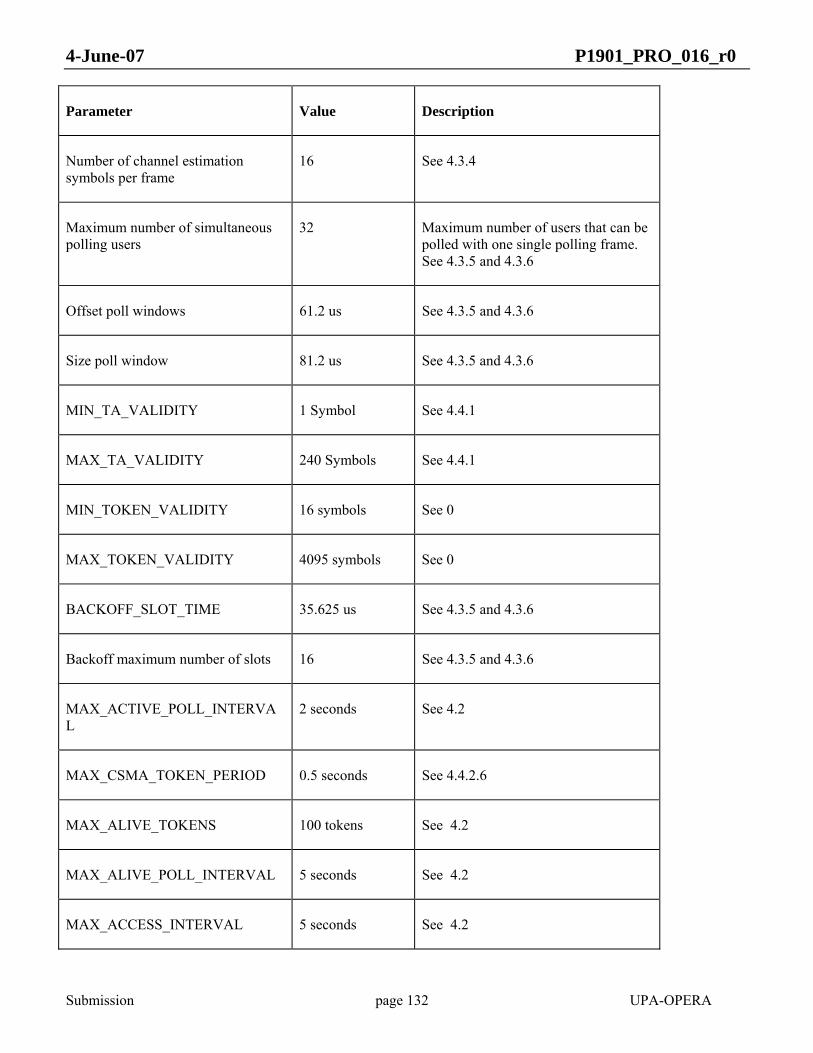
4-June-07 P1901_PRO_016_r0
Submission page 132 UPA-OPERA
Parameter Value Description
Number of channel estimation symbols per frame
16 See 4.3.4
Maximum number of simultaneous polling users
32 Maximum number of users that can be polled with one single polling frame. See 4.3.5 and 4.3.6
Offset poll windows 61.2 us See 4.3.5 and 4.3.6
Size poll window 81.2 us See 4.3.5 and 4.3.6
MIN_TA_VALIDITY 1 Symbol See 4.4.1
MAX_TA_VALIDITY 240 Symbols See 4.4.1
MIN_TOKEN_VALIDITY 16 symbols See 0
MAX_TOKEN_VALIDITY 4095 symbols See 0
BACKOFF_SLOT_TIME 35.625 us See 4.3.5 and 4.3.6
Backoff maximum number of slots 16 See 4.3.5 and 4.3.6
MAX_ACTIVE_POLL_INTERVAL
2 seconds See 4.2
MAX_CSMA_TOKEN_PERIOD 0.5 seconds See 4.4.2.6
MAX_ALIVE_TOKENS 100 tokens See 4.2
MAX_ALIVE_POLL_INTERVAL 5 seconds See 4.2
MAX_ACCESS_INTERVAL 5 seconds See 4.2

4-June-07 P1901_PRO_016_r0
Submission page 133 UPA-OPERA
Channel Estimation Maximum Period 10 seconds Channel Estimation Frame should be sent at least every Channel Estimation Maximum Period.
ACCEPTATION_TO 5 seconds See 4.3.9
INTER FRAME SPACE 1 189 µs Time distance between the end of a Distributor Frame and the beginning of the transmission of the first node of the distribution list. See 4.3.1.
INTER FRAME SPACE 2 126 µs Time distance between the end of a Data Frame and the beginning of the transmission of the next node on the distribution list. See 4.3.1.
Table 12 MAC parameter specification
4.7 MAC service specification (MAC SAP)
4.7.1 MAC service primitives
Following table shows MAC-DATA, MAC-ACK and MAC-MNT primitives:
Primitive Type

4-June-07 P1901_PRO_016_r0
Submission page 134 UPA-OPERA
MAC-DATA.req Request MAC-DATA.cnf Confirm MAC-DATA.ind Indication MAC-ACK.req Request MAC-ACK.cnf Confirm MAC-ACK.ind Indication MAC-MNT-TOKEN.req Request MAC-MNT-TOKEN.ind Indicate MAC-MNT-TOKEN.cnf Confirm MAC-MNT-RESOURCES.req Request MAC-MNT-RESOURCES.ind Indication MAC-MNT-RESOURCES.cnf Confirm MAC-MNT-CHANEST-FRAME.req Request MAC-MNT-CHANEST-REQ.req Request MAC-MNT-CHANEST-REQ.ind Indication MAC-MNT-NHOPS.req Request MAC-MNT-NHOPS.cnf Confirm MAC-MNT-CHANGE.req Request MAC-MNT-CHANGE.cnf Confirm MAC-MNT-TXSYMB.ind Indication MAC-MNT-CHANSTATS.req Request MAC-MNT-CHANSTATS.cnf Confirm MAC-MNT-NEWMID.ind Indication PHY-MNT-LINK-STATUS.req Request PHY-MNT-LINK-STATUS.cnf Confirm
Table 13 MAC sevice primitives
4.7.2 MAC-DATA.req
4.7.2.1 Function
This primitive requests a transfer of a LPDU from a local LLC layer entity.
4.7.2.2 Semantics of the service primitive
MAC-DATA.req(LPDU):
- LPDU: LLC Protocol Data Unit (MSDU)

4-June-07 P1901_PRO_016_r0
Submission page 135 UPA-OPERA
4.7.2.3 When generated
The primitive is generated by the LLC layer entity when a LPDU is to be transferred.
4.7.2.4 Effect of receipt
The MAC layer entity starts the sending of the LPDU.
4.7.3 MAC-DATA.cnf
4.7.3.1 Function
This primitive has local significance and provides the LLC layer with status information (sending finished) of the corresponding preceeding PHY-DATA.req primitive.
4.7.3.2 Semantics of the service primitive
This primitive has no parameters.
4.7.3.3 When generated
The primitive is passed from the MAC layer entity to the LLC layer entity to indicate that the previous LPDU has been sent.
4.7.3.4 Effect of receipt
The LLC layer entity is aware that the MAC is available to send new MPDUs, and can issue new MAC-DATA.req primitives.
4.7.4 MAC-DATA.ind
4.7.4.1 Function
This primitive defines the transfer of a LPDU from the MAC layer entity to the LLC layer entity.
4.7.4.2 Semantics of the service primitive
MAC-DATA.ind(LPDU, lpdu_seq_number)
- LPDU: LLC Protocol Data Unit - lpdu_seq_number: a sequence number that uniquily identifies this LPDU.

4-June-07 P1901_PRO_016_r0
Submission page 136 UPA-OPERA
4.7.4.3 When generated
The primitive is passed from the MAC layer entity to the LLC layer entity to indicate the arrival of a LPDU.
4.7.4.4 Effect of receipt
The LLC layer entity processes the newly received LPDU.
4.7.5 MAC-ACK.req
4.7.5.1 Function
This primitive requests the acknowledgment of a previously received LPDU.
4.7.5.2 Semantics of the service primitive
MAC-ACK.req(lpdu_seq_number):
- lpdu_seq_number: the sequence number of the LPDU to be acknowledged.
4.7.5.3 When generated
This primitive is generated by the LLC layer entity when a previously received LPDU is to be acknowledged.
4.7.5.4 Effect of receipt
The MAC layer entity stores the lpdu_seq_number to be acknowledged, and will send the acknowledgment in the proper subsequent MPDU.
4.7.6 MAC-ACK.cnf
4.7.6.1 Function
This primitive has local significance and provides the LLC layer with status information (acknowledgment sent) of the corresponding preceeding MAC-ACK.req primitive.
4.7.6.2 Semantics of the service primitive
This primitive has no parameters.

4-June-07 P1901_PRO_016_r0
Submission page 137 UPA-OPERA
4.7.6.3 When generated
This primitive is passed from the MAC suplayer entity to the LLC layer entity to indicate that the previously requested LPDU acknowledgment has been sent.
4.7.6.4 Effect of receipt
The LLC layer entity is aware that the previously requested LPDU acknowledgment has been sent and can issue new MAC-ACK.req primitives
4.7.7 MAC-ACK.ind
4.7.7.1 Function
This primitive indicates the LLC layer entity that an LPDU acknowledgment has been received.
4.7.7.2 Semantics of the service primitive
MAC-ACK.ind(lpdu_seq_number):
- lpdu_seq_number: the sequence number of the acknowledged LPDU.
4.7.7.3 When generated
This primitive is passed from the MAC layer entity to the LLC layer entity to indicate that an LPDU acknowledgment has been received.
4.7.7.4 Effect of receipt
The LLC marks the corresponding LPDU as correctly acknowledged by the peer LLC entity.
4.7.8 MAC-MNT-TOKEN.req
4.7.8.1 Function
This primitive requests the sending of a token.
4.7.8.2 Semantics of the service primitive
MAC-MNT-TOKEN.req(token):
- token (see 4.4.2): MAC delimiter: Distributor token, Data token, Silence token, Access Token, Access Reply token, Polling token, TDR Polling token, Non-returnable Data token, CSMA token, Clock token

4-June-07 P1901_PRO_016_r0
Submission page 138 UPA-OPERA
4.7.8.3 When generated
This primitive is generated by the Management layer to send the token to other nodes, or to send special tokens. This primitive is used to schedule the access to the channel.
4.7.8.4 Effect of receipt
The MAC layer sends the requested token inside the current MPDU.
4.7.9 MAC-MNT-TOKEN.ind
4.7.9.1 Function
This primitive indicates the reception of a token, and defines the transfer of the information received in the token to the Management layer.
4.7.9.2 Semantics of the service primitive
MAC-MNT-TOKEN.ind(token):
- token (see 4.4.2): MAC delimiter: Distributor token, Data token, Silence token, Access Token, Access Reply token, Polling token, TDR Polling token, Non-returnable Data token, CSMA token, Clock token
4.7.9.3 When generated
This primitive is generated by the MAC layer to indicate the reception of a token and provides the corresponding information used by the Management layer entity in protocols such as Access Protocol or QoS.
4.7.9.4 Effect of receipt
Depending on the token parameter, the Management layer entity may perform different actions (see sections 4, 8, 9 and 11).
4.7.10 MAC-MNT-TOKEN.cnf
4.7.10.1 Function
This primitive is generated by the MAC layer to inform about the result of the MAC-MNT-TOKEN.req primitive. That is, if the required token has been successfully sent.
4.7.10.2 Semantics of the service primitive
MAC-MNT-TOKEN.cnf (token, result):

4-June-07 P1901_PRO_016_r0
Submission page 139 UPA-OPERA
- token: Requested token (see 4.4.2). Distributor token, Data token, Silence token, Access token, Access Reply token, Polling token, TDR Polling token, Non-returnable Data token, CSMA token, Clock token
- result: [SUCCESS|FAIL]. FAIL can be produced if the nodes losses a contention after a CSMA token.
4.7.10.3 When generated
The primitive is generated by the MAC layer to confirm the result of trying to send the requested token.
4.7.10.4 Effect of receipt
The Management layer entity shall take the proper actions taking into account the result parameter (see sections 4, 8, 9, 10).
4.7.11 MAC-MNT-RESOURCES.req
4.7.11.1 Function
This primitive requests the allocation or release of local MAC resources.
4.7.11.2 Semantics of the service primitive
MAC-MNT-RESOURCES.req (MAC, type, service_class, latency, BW) :
- MAC: MAC address of the traffic source - type: type of request. [ALLOCATE|FREE] - service_class: Service class of the traffic flow - latency: latency requirement of the flow - BW: bandwidth requirement of the flow
4.7.11.3 When generated
The primitive is generated by the Management layer entity to allocate resources for one traffic flow, or free them.
4.7.11.4 Effect of receipt
If there are enough resources, they are allocated. The primitive MAC-MNT-RESOURCES.conf indicates the status of this allocation.
4.7.12 MAC-MNT-RESOURCES.ind
4.7.12.1 Function
This primitive indicates a change of the resources that a traffic flow can use.

4-June-07 P1901_PRO_016_r0
Submission page 140 UPA-OPERA
4.7.12.2 Semantics of the service primitive
MAC-MNT-RESOURCES.ind(MAC, type, prio, latency, BW):
- MAC: MAC address of the traffic source. - type: type of indication. [NO_RESOURCES|RESOURCES_CHANGE]. - service_class: service class of the traffic flow - latency: latency requirement of the flow - BW: bandwidth requirement of the flow. (BW can be lower than requested when type is
RESOURCES_CHANGE)
4.7.12.3 When generated
The primitive is passed by the MAC layer entity to the Management layer entity to indicate that the resources of a traffic flow have changed.
4.7.12.4 Effect of receipt
The Management layer is aware of the change in the resources allocated to the traffic flow, and shall take this result into account when performing the CAC protocol.
4.7.13 MAC-MNT-RESOURCES.cnf
4.7.13.1 Function
This primitive indicates the result of the previously requested allocation of local resources.
4.7.13.2 Semantics of the service primitive
MAC-MNT-RESOURCES.cnf (MAC, type, service_class, latency, BW):
- MAC: MAC address of the traffic source. - type: type of confirmation. [OK|NO_RESOURCES] - service_class: service_class of the traffic flow - latency: latency requirement of the flow - BW: bandwidth requirement of the flow. (BW can be lower than requested when type is OK).
4.7.13.3 When generated
The primitive is passed by the MAC layer entity to the Management layer entity to indicate the result of the previously requested allocation of local resources.
4.7.13.4 Effect of receipt
The Management layer is aware of the result of the previous MAC-MNT-RESOURCES.req primitive, and shall take this result into account when performing the CAC protocol.

4-June-07 P1901_PRO_016_r0
Submission page 141 UPA-OPERA
4.7.14 MAC-MNT-CHANEST-FRAME.req
4.7.14.1 Function
This primitive requests the transmission of a Channel Estimation frame to the local MAC layer entity.
4.7.14.2 Semantics of the service primitive
This primitive has no parameters.
4.7.14.3 When generated
The primitive can be generated in two situations:
- The Management layer periodically shall issue this primitive. - A MAC-MNT-CHANEST-REQ.ind primitive has been received.
4.7.14.4 Effect of receipt
The MAC layer entity shall transmit a Channel Estimation frame.
4.7.15 MAC-MNT-CHANEST-REQ.req
4.7.15.1 Function
This primitive requests the sending of a Channel Estimation frame petition to a given node.
4.7.15.2 Semantics of the service primitive
MAC-MNT-CHANEST-REQ.req (dest_MAC) :
- dest_MAC: MAC address of the node that is requested to send the Channel Estimation frame.
4.7.15.3 When generated
This primitive shall be generated by the Management layer when it considers that the tonemap used to receive transmissions from a given node may have changed.
4.7.15.4 Effect of receipt
The MAC layer entity shall fill a Data token addressed to the dest_MAC address with the Channel Estimation Frame Request set to 1.

4-June-07 P1901_PRO_016_r0
Submission page 142 UPA-OPERA
4.7.16 MAC-MNT-CHANEST-REQ.ind
4.7.16.1 Function
This primitive indicates the Management layer that a Channel Estimation frame request from a node has been received.
4.7.16.2 Semantics of the service primitive
MAC-MNT-CHANEST-REQ.ind(src_MAC):
- src_MAC: MAC address of the requester.
4.7.16.3 When generated
The primitive is generated by the MAC layer entity to indicate that a node has requested the transmission of a Channel Estimation frame.
4.7.16.4 Effect of receipt
When receiving this primitive, the Management layer entity shall decide to issue the MAC-MNT-CHANEST-FRAME.req in order to transmit the Channel Estimation frame.
4.7.17 MAC-MNT-NHOPS.req
4.7.17.1 Function
This primitive requests the MAC layer for the number of hops that the node is from a master.
4.7.17.2 Semantics of the service primitive
MAC-MNT-NHOPS.req(MAC):
- MAC: MAC address of the master
4.7.17.3 When generated
The primitive is generated when the Management layer needs to know the number of hops from a master node.
4.7.17.4 Effect of receipt
The MAC layer obtains the number of hops and passes this information to the Management layer by means of the MAC-MNT-NHOPS.cnf primitive.

4-June-07 P1901_PRO_016_r0
Submission page 143 UPA-OPERA
4.7.18 MAC-MNT-NHOPS.cnf
4.7.18.1 Function
This primitive indicates the result of the previously requested number of hops.
4.7.18.2 Semantics of the service primitive
MAC-MNT-NHOPS.cnf(nhops):
- nhops: number of hops between local node and requested master.
4.7.18.3 When generated
The primitive is passed by the MAC layer entity to the Management layer entity to provide the number of hops.
4.7.18.4 Effect of receipt
The Management layer uses this number of hops in several management and configuration protocols.
4.7.19 MAC-MNT-CHANGE.req
4.7.19.1 Function
This primitive is used to change the role of the node (master/slave) in the PLC cell.
4.7.19.2 Semantics of the service primitive
MAC-MNT-CHANGE.req (role, new_master):
- role: [MASTER|SLAVE] - new_master: MAC address of the node that has to be considered as the new master. This parameter shall be
used when the role is SLAVE.
4.7.19.3 When generated
The primitive is issued by the Management layer entity in the framework of the Coordination tools (see ¡Error! No se encuentra el origen de la referencia.).
4.7.19.4 Effect of receipt
The MAC layer shall play the role indicated in the parameters.

4-June-07 P1901_PRO_016_r0
Submission page 144 UPA-OPERA
4.7.20 MAC-MNT-CHANGE.cnf
4.7.20.1 Function
This primitive is used to inform that the requested change has been done.
4.7.20.2 Semantics of the service primitive
This primitive has no parameters.
4.7.20.3 When generated
It is generated by the MAC layer when the role has been changed.
4.7.20.4 Effect of receipt
The Management layer receives the confirmation of the change.
4.7.21 MAC-MNT-TXSYMB.ind
4.7.21.1 Function
This primitive is used to inform the Management layer about the number of information symbols transmitted to a given node.
4.7.21.2 Semantics of the service primitive
MAC-MNT-TXSYMB.ind (num_symb, port):
- num_symb: number of symbols transmitted. - port: local transmission port
4.7.21.3 When generated
This primitive is generated by the MAC layer entity after each transmission.
4.7.21.4 Effect of receipt
Upon the reception of this primitive, the Management layer can estimate the required bandwidth by a traffic flow. It can also estimate the latencies that the traffic flow is suffering.
4-June-07 P1901_PRO_016_r0
Submission page 145 UPA-OPERA
4.7.22 MAC-MNT-CHANSTATS.req
4.7.22.1 Function
This primitive is used to gather MAC statistics about the channel state.
4.7.22.2 Semantics of the service primitive
This primitive has no parameters.
4.7.22.3 When generated
The primitive is generated by the Management layer when it needs to know the statistics to perform the functions described in sections 8, 9 and 11.
4.7.22.4 Effect of receipt
The MAC layer entity communicates the required information by means of the MAC-MNT-CHANSTATS.cnf primitive.
4.7.23 MAC-MNT-CHANSTATS.cnf
4.7.23.1 Function
This primitive is used by the MAC layer to communicate the required statistics.
4.7.23.2 Semantics of the service primitive
MAC-MNT-CHANSTATS.cnf (stats):
- stats: composed by this information: o cont_win: number of won contention attempts o cont_attemp: number of contention attempts o num_nodes: number of detected nodes o used_val_rate: vector (one value per priotity): % of the assigned validity that has been used by the
slaves o req_val_rate: vector (one value per service class): % of the available validity that has been
requested o empy_CSMA: number of unsued CSMA tokens by the slaves o CSMA_usage: % of the assigned validity in CSMA tokens that has been used by the slaves
4.7.23.3 When generated
It is generated as a response to the MAC-MNT-CHANSTATS.req primitive.

4-June-07 P1901_PRO_016_r0
Submission page 146 UPA-OPERA
4.7.23.4 Effect of receipt
The Management layer can use the information to perform the functions described in sections 8, 9 and 11.
4.7.24 MAC-MNT-NEWMID.ind
4.7.24.1 Function
This primitive is used to notify the Management layer that a different MID has been detected.
4.7.24.2 Semantics of the service primitive
MAC-MNT-NEWMID.ind (new_mid):
- new_mid: new MID detected
4.7.24.3 When generated
This primitive is generated by the MAC layer entity when it detects in the channel a MID different than the own MID.
4.7.24.4 Effect of receipt
The Management layer entity uses this information to perform the coordination among different BPL Cells.
4.7.25 MAC-MNT-LINK-STATUS.req
4.7.25.1 Function
This primitive requests to the MAC layer the link status of the communication with certain MAC.
4.7.25.2 Semantics of the service primitive
MAC-MNT-LINK-STATUS.req (MAC):
• MAC: MAC address
4.7.25.3 When generated
The primitive is generated when the Management layer needs to know the status of certain link.

4-June-07 P1901_PRO_016_r0
Submission page 147 UPA-OPERA
4.7.25.4 Effect of receipt
The current link status is obtained by the MAC layer and passed to the Management layer by means of the MAC-MNT-LINK-STATUS.req primitive.
4.7.26 MAC-MNT-LINK-STATUS.cnf
4.7.26.1 Function
This primitive indicates the link status of the communication with certain MAC.
4.7.26.2 Semantics of the service primitive
MAC-MNT-LINK-STATUS.cnf (MAC,link_status):
• MAC: MAC address • Link Status: Linked (1) or not linked (0)
4.7.26.3 When generated
The primitive is generated when the Management layer needs to know the status of certain link.
4.7.26.4 Effect of receipt
The Maganement layer gets the link status.
5 LLC
5.1 INTRODUCTION
The LLC layer receives packets (Convergence Layer PDUs) from the Convergence Layer and transmits LLC PDUs to the MAC layer. LLC tasks are:
• Segmentation and grouping of packets (CLPDUs) to create the payloads of the bursts.
• The addition of an inter-packet header to every packet or fragment of packet
• The addition of an LLC delimiter (Burst Header) to the payload of every burst payload.
• The addition of the CCMP Header at the beginning of each burst when burst is set as encrypted.
• The addition of a Message Integrity Check (MIC) to every fragment of packet or packet when burst is set as encrypted.
4-June-07 P1901_PRO_016_r0
Submission page 148 UPA-OPERA
• The addition of a Cyclic Reduncancy Check (CRC) to every fragment of packet or packet when burst is set as unencripted.
• The Packet ACK Protocol (PAP) for sequence control and selective acknowledgement of packets (CLPDUs).
5.2 BURST HEADER
There are two types of burst header, one with data and other one without data.
5.2.1 Burst header with data
The Burst Header is the LLC Delimiter which precedes every burst. It has the following fields:
- Preamble – 32 bits. Always set to 0xBDADC3.
- TMI – 4 bits. Tonemap ID. Tonemap used in the data encoding. TMI 0 is reserved for HURTO mapping.
- Version – 3 bits. Set to 0.
- Transmission Port – 7 bits. Local Port of the intended receiver of the Burst.
- APL – 14 bits. Aggregated Payload Length. Length of the payload in 32-bit words of the current burst, including RS FEC redundancy. The APL will be defined by the RS FEC redundancy used and the length of the data included in the burst.
- FEC payload – 6 bits. RS Fordward Error Correction codeword payload length in 32-bit words. The RS FEC codeword payload allowed values are indicated in Table 2. The FEC Redundancy + FEC payload has to be less or equal to 63 words.
- FEC Redundancy – 2 bits. RS Fordward Error Correction codeword redundancy length:
o 0: 8 redundancy bytes (2 words)
o 1: 12 redundancy bytes (3 words)
o 2: 16 redundancy bytes (4 words)
o 3: 20 redundancy bytes (5 words)
- BPS –14 bits. Bits Per Symbol for the current burst. It depends on the encoding used for the current transmission. Possible values range from 24 to 14592. The BPS calculation (See Equation 17) includes the RS redundancy and excludes the 4D-TCM. With the BPS and APL values nodes that are not the destination of the burst, but that may be the destination of subsequent bursts in the same frame, may calculate the burst duration in symbols in order to know when the next burst header or token is going to be placed.
- HURTO – 1 bit. It shall be set to 1 when the burst is transmitted in HURTO mode.
- Dummy Hdr– 1 bit. It shall be set to 1 if the burst is not carrying data symbols.

4-June-07 P1901_PRO_016_r0
Submission page 149 UPA-OPERA
- PAP Code Type – 1 bit. Packet ACK Protocol Codification Type. It is set to 0 when Run-Length Encoding is used and set to 1 when GroupEncoding is used.
• Crypto AES– 1 bit. Shall be set to 1 when the burst is encrypted.
- ACK Info – 1 bit. Shall be set to 1 when the burst header contains Packet ACK Protocol information (see 5.4).
- PAP Info – 55 bits. The meaning of these bits depends on PAP Code Type. See section 5.4
- PAP Port – 7 bits. Local Port over which the ACK contained in the Burst Header takes effect.
- PAP Init – 1 bit. The first packet that requires ACK (Req ACK field in the Interpacket Header) in the burst has the lowest packet id stored in transmission buffer. The receiver cannot request retransmissions of previous packets ids.
- PAP Reset – 1 bit. Reset the reception buffer.
- PAP Last Received Packet – 12 bits. Last received packet information used by Packet ACK Protocol. See section 5.4
- Service class – 8 bits. Indicates the service classes belonging to the packets contained in the burst. If bit X is equal to 1, there is at least one packet in this burst with service class X.
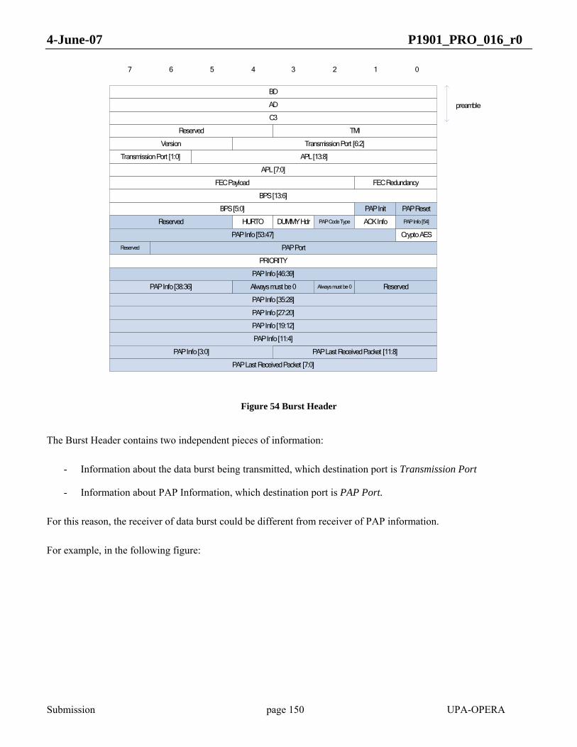
4-June-07 P1901_PRO_016_r0
Submission page 150 UPA-OPERA
BD
01234567
AD
C3
TMI
Version
Transmission Port [1:0]
APL [7:0]
FEC Payload
BPS [13:6]
BPS [5:0]
Reserved
PRIORITY
Reserved
Transmission Port [6:2]
APL [13:8]
FEC Redundancy
PAP Init
HURTO DUMMY Hdr ACK InfoPAP Code Type
PAP Port
PAP Last Received Packet [7:0]
preamble
Crypto AES
Always must be 0 Always must be 0
PAP Last Received Packet [11:8]
PAP Info [53:47]
PAP Info [46:39]
PAP Info [38:36]
PAP Info [54]
PAP Info [27:20]
PAP Info [19:12]
PAP Info [11:4]
PAP Info [35:28]
PAP Info [3:0]
PAP Reset
Reserved
Reserved
Figure 54 Burst Header
The Burst Header contains two independent pieces of information:
- Information about the data burst being transmitted, which destination port is Transmission Port
- Information about PAP Information, which destination port is PAP Port.
For this reason, the receiver of data burst could be different from receiver of PAP information.
For example, in the following figure:
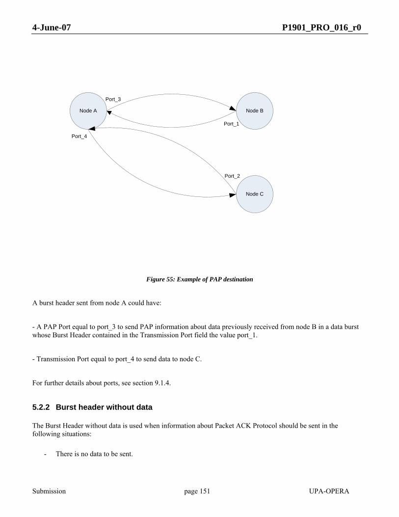
4-June-07 P1901_PRO_016_r0
Submission page 151 UPA-OPERA
Node A Node B
Node C
Port_3
Port_1
Port_4
Port_2
Figure 55: Example of PAP destination
A burst header sent from node A could have:
- A PAP Port equal to port_3 to send PAP information about data previously received from node B in a data burst whose Burst Header contained in the Transmission Port field the value port_1.
- Transmission Port equal to port_4 to send data to node C.
For further details about ports, see section 9.1.4.
5.2.2 Burst header without data
The Burst Header without data is used when information about Packet ACK Protocol should be sent in the following situations:
- There is no data to be sent.

4-June-07 P1901_PRO_016_r0
Submission page 152 UPA-OPERA
- The Packet ACK Protocol information has too many errors if it is sent in a Burst Header because limitation of used PAP codification.
Thefollowing are the fields with significant information:
- Preamble – 32 bits. Always set to 0xBDADC3
- TMI – 4 bits. Tonemap ID. Tonemap used in the data encoding. TMI 0 is reserved for HURTO mapping.
- Version – 3 bits. Set to 0.
- Dummy Hdr– 1 bit. It shall be set to 1 if the burst is not carrying data symbols.
- PAP Code Type – 1 bit. Packet ACK Protocol Codification Type. It is set to 0 when Run-Length Encoding. And set to 1 when GroupEncoding.
- ACK Info – 1 bit. Shall be set to 1 when the burst header contains Packet ACK Protocol information. See section 5.4.
- PAP Info – 119 bits. The meaning of these bits depends on PAP Code Type. See section 5.4
- PAP Port – 7 bits. Local Port over which the ACK contained in the Burst Header takes effect.
- PAP Last Received Packet – 12 bits. Last received packet information used by Packet ACK Protocol. See section 5.4
The rest of the fields shall be ignored in reception.

4-June-07 P1901_PRO_016_r0
Submission page 153 UPA-OPERA
BD
01234567
AD
C3
TMI
Version
PAP Info [73:70]
PAP Info [60]
PAP Info [118:114]
DUMMY Hdr ACK InfoPAP Code Type
PAP Port
PAP Last Received Packet [7:0]
preamble
PAP Last Received Packet [11:8]
PAP Info [69]
PAP Info [27:20]
PAP Info [19:12]
PAP Info [11:4]
PAP Info [35:28]
PAP Info [3:0]
PAP Info [105:98]
PAP Info [113:106]
PAP Info [43:36]
PAP Info [89:82]
PAP Info [97:90]
PAP Info [68:61]
PAP Info [81:74]
PAP Info [59:52]
PAP Info [51:44]
Reserved
Figure 56: Burst Header without Data
5.3 BURST STRUCTURE
Two possible burst structures are supported. First one is used in the case of unencrypted burst, and second one is devoted to encrypted bursts.
5.3.1 Unencrypted Burst Structure
When Cripto AES bit in the Burst Header is set to 0, the burst shall be composed by a Burst Header delimiter followed by a data payload including one or several fragmented and/or completed packets. A Burst Header delimiter without any following data payload is used to send PAP information when there are no data to be sent as described in section 5.2.2.
Note: The Burst Header is a delimiter processed by the PHY layer as described in 3.3.1. It is transmitted in HURTO mode over one single symbol. The data payload is processed by the PHY layer as described in 3.3.2. The data payload may use HURTO or adaptive mapping. It can be transmitted over one or several symbols.
The Unencrypted Burst could have the following structures:
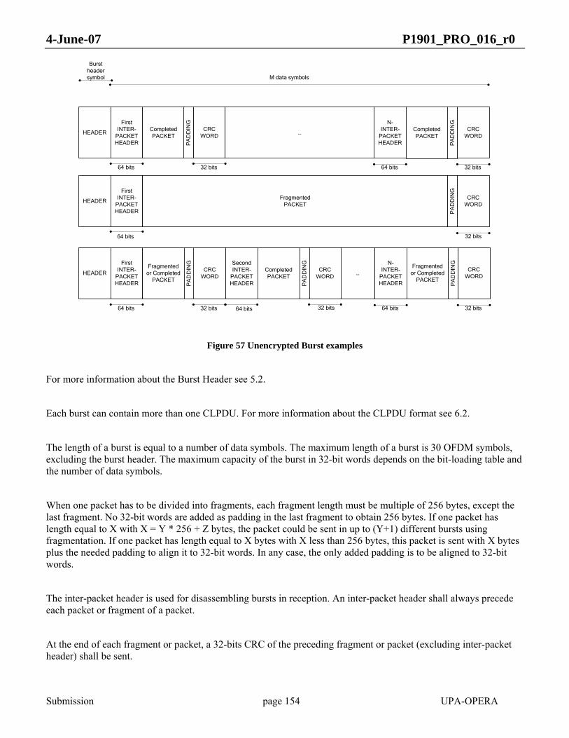
4-June-07 P1901_PRO_016_r0
Submission page 154 UPA-OPERA
HEADER
FirstINTER-
PACKETHEADER
CompletedPACKET
CRC WORD
N-INTER-
PACKETHEADER
CRC WORD
64 bits 32 bits 64 bits 32 bits
PA
DD
ING
CompletedPACKET
…
Burst header symbol M data symbols
HEADER
FirstINTER-
PACKETHEADER
FragmentedPACKET
CRC WORD
64 bits 32 bits
HEADER
FirstINTER-
PACKETHEADER
Fragmented or Completed
PACKET
CRC WORD
N-INTER-
PACKETHEADER
CRC WORD
64 bits 32 bits 64 bits 32 bits
PA
DD
ING
Fragmented or Completed
PACKET…
SecondINTER-
PACKETHEADER
CompletedPACKET
CRC WORD
32 bits64 bitsP
AD
DIN
G
PA
DD
ING
PA
DD
ING
PA
DD
ING
Figure 57 Unencrypted Burst examples
For more information about the Burst Header see 5.2.
Each burst can contain more than one CLPDU. For more information about the CLPDU format see 6.2.
The length of a burst is equal to a number of data symbols. The maximum length of a burst is 30 OFDM symbols, excluding the burst header. The maximum capacity of the burst in 32-bit words depends on the bit-loading table and the number of data symbols.
When one packet has to be divided into fragments, each fragment length must be multiple of 256 bytes, except the last fragment. No 32-bit words are added as padding in the last fragment to obtain 256 bytes. If one packet has length equal to X with X = Y * 256 + Z bytes, the packet could be sent in up to (Y+1) different bursts using fragmentation. If one packet has length equal to X bytes with X less than 256 bytes, this packet is sent with X bytes plus the needed padding to align it to 32-bit words. In any case, the only added padding is to be aligned to 32-bit words.
The inter-packet header is used for disassembling bursts in reception. An inter-packet header shall always precede each packet or fragment of a packet.
At the end of each fragment or packet, a 32-bits CRC of the preceding fragment or packet (excluding inter-packet header) shall be sent.

4-June-07 P1901_PRO_016_r0
Submission page 155 UPA-OPERA
Packet fragments shall only appear at the beginning or the end of the burst. Once a fragment of a packet is sent in a burst, the rest of the packet shall be sent before any other packet to the same Local Port (regardless of service class).
Packets with the same destination port and same service class shall be transmitted in order. Within the same destination port, packets are transmitted according to their service class, with highest service class packets first (see 8.2).
The inter-packet header has the following structure:
Octet
1
Part of Packet
0123457 6
2
3
Version
Length [5:0]
4
Unfinished Last Packet ACK Req Packet Id [11:8]
Length [8:6]
Padding Last Word
Packet Id [7:0]
CRC – 16 bits
5
6
Fragment Number
5D
7
8
Reserved
Figure 58 Inter-packet header
- Preamble – 8 bits. Set to 0x5D
- Part of Packet – 1 bit. The first fragment in the burst is part of a previous packet. This field shall only be checked by the receiver in the first inter-packet header.
- Unfinished – 1 bit. The last fragment in this burst is unfinished. To be set to one in the last inter-packet header if it is not a complete packet.
- Last Packet – 1 bit. This is the last fragment or packet inside this burst.
- ACK Req – 1 bit. The transmitter is waiting an ACK about this packet to free it. When it is set to 0, the transmitter frees this packet when this packet is sent and the receiver can not request retransmissions about it.
- Packet Id – 12 bits. Unique identification of each packet.
- Version – 2 bits. Version is set to 0.
- Fragment number – 3 bits. Each packet could be divided into 6 fragments. This is the identification of each fragment: from 0 to 5.
- Length – 9 bits. Length of the packet or fragment in words.

4-June-07 P1901_PRO_016_r0
Submission page 156 UPA-OPERA
- Padding Last Word – 2 bits. Number of padding bytes of the last word of the packet or fragment of a packet.
- CRC – 16 bits. 16 bits CRC of the preceding 48-bits.
5.3.2 Encrypted Burst Structure
When Cripto AES bit in the Burst Header is set to 1, the burst shall be composed by a Burst Header delimiter followed by a CCMP Header of 64 bits length whose composition and fields are described in section 10.1. After the CCMP Header, data payload including one or several fragmented and/or completed packets is added to the burst. Each packet fragment or packet includes a Message Integrity Check (MIC) to preserve the integrity of each unit as described in section 10.1.
The Encrypted Burst could have the following structures:
HEADER
FirstINTER-
PACKETHEADER
CompletedPACKET
MIC
N- INTER-
PACKETHEADER
MIC
64 bits 32 bits 64 bits 32 bits
PA
DD
ING
CompletedPACKET
…
Burst header symbol M data symbols
HEADERCCMP Header
FragmentedPACKET
MIC
64 bits 32 bits
HEADER
FirstINTER-
PACKETHEADER
Fragmented or
CompletedPACKET
MIC
N- INTER-
PACKETHEADER
MIC
64 bits 32 bits 64 bits 32 bits
PA
DD
INGFragmented
or CompletedPACKET
…
SecondINTER-
PACKETHEADER
CompletedPACKET
MIC
32 bits64 bits
PA
DD
ING
PA
DD
ING
PA
DD
ING
PA
DD
ING
CCMP Header
64 bits
FirstINTER-
PACKETHEADER
64 bits
CCMP Header
64 bits
Figure 59 Encrypted Burst examples
Each MIC is calculated over the Burst Header, CCMP Header, its correspondent Interpacket Header, the packet or fragment of packet itself and the padding, but Burst Header and CCMP Header are sent only once at the beginning of the burst. More information about algorithms and field composition is given in section 10.1.
Restrictions and rules regarding packet fragmentation in unencrypted burst remains the same for encrypted bursts.

4-June-07 P1901_PRO_016_r0
Submission page 157 UPA-OPERA
5.4 Packet ACK Protocol
The Packet ACK Protocol has the following functions:
1) Control of sequence of received packets in the receiver
2) Acknowledge of correct received packets and request of retransmission of no received or incorrect packets
Each packet can be sent in one of the following modes:
a) No ACK mode: The receiver cannot request any retransmission of this packet. The packet id is only used to reassembling fragments of one packet. The Req ACK bit in inter-packet header is set to 0 in this case.
b) ACK mode: The receiver can do a sequence control, reassembling fragments of one packet and request retransmissions. The receiver is the responsible for sending ACKs to the transmitter about the receive packet. The Req ACK bit in inter-packet header is set to 1 in this case.
The Packet ACK Protocol (PAP) uses fields located in the Burst Header or in the inter-packet header to perform the ACK algorithm:
• ACK Info - 1 bit. Active when the Burst Header contains PAP information.
• PAP Port – 7 bits: Local port of this PAP information
• PAP Last Received Packet – 12 bits: Packet ID of last Received Packet . Used to decode PAP Information.
• PAP Code Type – 1 bit: Packet ACK Protocol Codification Type. It is set to 0 when performing Run-Length Encoding and set to 1 when performing Group Encoding.
• PAP Info – 119 bits in case of Burst Header without data. And 55 bits in case of Burst Header with data. . The meaning of these bits depends on PAP Code Type as explained below.
• PAP Init – 1 bit. The receiver should move the reception buffer in order to have as first packet identification the first ACK Req packet identification from this burst.
• Packet Id – 12 bits: Unique identification of each packet.
• Fragment number – 3 bits: Each packet could be divided into 6 fragments. This is the identification of each fragment: from 0 to 5.
• ACK Req – 1 bit. The transmitter is waiting an ACK about this packet to free it. When it is set to 0, the transmitter frees this packet when this packet is sent and the receiver can not request retransmissions about it.
In case of ACK Req packets are transmitted, the receiver shall inform the transmitter about how the packets were received. Since the packet windows size is 2048 packets, 2048 bits shall be sent back to the transmitter so that it can free the correctly received packets and retransmit the packets that have been received incorrectly or not received. The feedback information shall be coded to fit in the allocated space. There are two types of encoding:

4-June-07 P1901_PRO_016_r0
Submission page 158 UPA-OPERA
- Group Encoding (see 5.4.2)
- Run-Length Encoding (see 5.4.3)
The PAP codification could have some errors due to limited space left in the Burst Header. An error in PAP codification consists on requesting retransmission of a correct received packet. Errors in the PAP codification that acknowledge a not received packet or an incorrect received packet are forbidden.
5.4.1 Transmission window management
Packets can be transmitted without receiving acks while there are free positions in the transmission window. An occupied position in the transmission window is a sent packet whose ack has not been received. If all the positions in the transmission window are occupied, a timer (ACK_TIMER) shall be started. If no ack is received before the timer expires, the packets inside the transmission window shall be sent again. After MAX_RTX timeouts, the window shall be cleared (packets removed from the transmission memory) and the next burst that will be sent to the same destination shall have the PAP Init bit set to 1.
5.4.2 Packet ACK Protocol: Group Encoding
When using Group Encoding, the status of the received packets is coded in a compressed format. Status is not expressed by individual packets but by groups of packets.
Groups shall be all the same length, and shall be formed starting from the most recently received packet id backwards to the oldest id.
The PAP information depends on the PAP Code Type and on PAP Algorithm (PAP Info bits [1:0]):
PAP Algorithm Description
0 Algorithm A (see section 5.4.2.1)
1 Algorithm B (see section 0)
2 Algorithm C (see section 5.4.2.3)
Table 14: PAP algorithm coding
In all these algorithms, the following information is used:
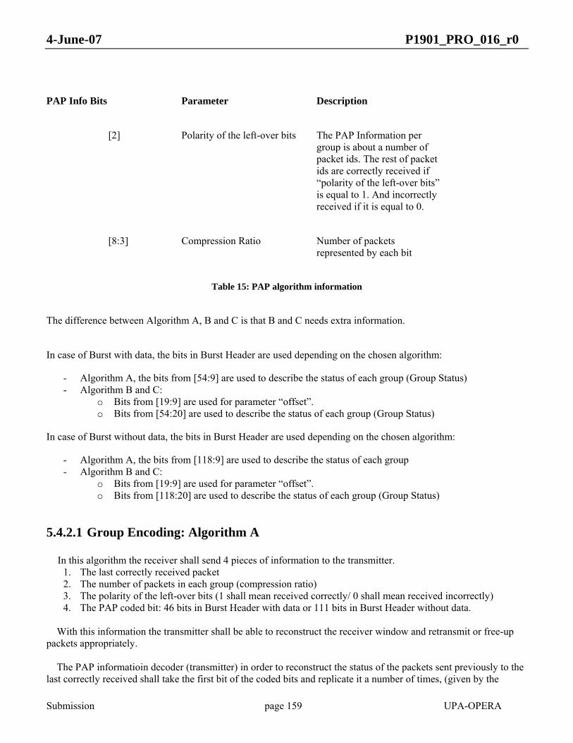
4-June-07 P1901_PRO_016_r0
Submission page 159 UPA-OPERA
PAP Info Bits Parameter Description
[2] Polarity of the left-over bits The PAP Information per group is about a number of packet ids. The rest of packet ids are correctly received if “polarity of the left-over bits” is equal to 1. And incorrectly received if it is equal to 0.
[8:3] Compression Ratio Number of packets represented by each bit
Table 15: PAP algorithm information
The difference between Algorithm A, B and C is that B and C needs extra information.
In case of Burst with data, the bits in Burst Header are used depending on the chosen algorithm:
- Algorithm A, the bits from [54:9] are used to describe the status of each group (Group Status) - Algorithm B and C:
o Bits from [19:9] are used for parameter “offset”. o Bits from [54:20] are used to describe the status of each group (Group Status)
In case of Burst without data, the bits in Burst Header are used depending on the chosen algorithm:
- Algorithm A, the bits from [118:9] are used to describe the status of each group - Algorithm B and C:
o Bits from [19:9] are used for parameter “offset”. o Bits from [118:20] are used to describe the status of each group (Group Status)
5.4.2.1 Group Encoding: Algorithm A In this algorithm the receiver shall send 4 pieces of information to the transmitter.
1. The last correctly received packet 2. The number of packets in each group (compression ratio) 3. The polarity of the left-over bits (1 shall mean received correctly/ 0 shall mean received incorrectly) 4. The PAP coded bit: 46 bits in Burst Header with data or 111 bits in Burst Header without data.
With this information the transmitter shall be able to reconstruct the receiver window and retransmit or free-up packets appropriately. The PAP informatioin decoder (transmitter) in order to reconstruct the status of the packets sent previously to the last correctly received shall take the first bit of the coded bits and replicate it a number of times, (given by the

4-June-07 P1901_PRO_016_r0
Submission page 160 UPA-OPERA
compression ratio), until completing the window (2048 bits). The group porder goes from the most recently received to least recently received (see Figure 60)
Last correctly received packet
ok
1
Compression ratio
PAP Coded Bits [0]
Compression ratio
PAP Coded Bits [1]
2048
Compression ratio
PAP Coded
Bits [last bit]
Polarity of lef-over bits
Figure 60: Packet ACK Protocol: Algorithm A
5.4.2.2 Packet ACK Protocol: Algorithm B This algorithm is similar to the algorithm A but one extra piece of information shall be sent:
• An offset that shall indicate where the next transition (status change) after the last correctly received packet (not including the offset itself) occurs.
In this algorithm, the status of the groups is described by 35 bits in Burst Header with data or 99 bits in Burst Header without data. With this information the PAP decoder (transmitter) shall take the previous packet to the last correctly received packet, and count backwards until the offset is reached and. It shall fill these spacespositions with either ones or zeros (depending on the polarity bit). After this, the decoding of the algorithm B shall be identical of that ofto the algorithm A. The process is described in the following figure:
Last correctly received packet
ok
1
Compression ratio
PAP Coded Bits [0]
Compression ratio
PAP Coded Bits [1]
2048
Compression ratio
PAP Coded
Bits [last bit]
Polarity of lef-over bits
Offset
NOT PAP
Coded Bits [0]
Figure 61: Packet ACK Protocol: Algorithm B

4-June-07 P1901_PRO_016_r0
Submission page 161 UPA-OPERA
5.4.2.3 Grouping Encoding: Algorithm C This algorithm is a variation of the algorithm B. The receiver shall send the same amount of data than in algorithm B but the transmitter shall decode it in a different way. The PAP decoder (transmitter) shall take the information and assume that from the starting point (this is the last correctly received packet) to the offsets, the packets were incorrectly received. And from the offset, it shall start the decoding in the same way as in algorithms A and B.
Last correctly received packet
ok
1
Compression ratio
PAP Coded Bits [0]
Compression ratio
PAP Coded Bits [1]
2048
Compression ratio
PAP Coded
Bits [last bit]
Polarity of lef-over bits
Offset
Incorrect
Figure 62: Packet ACK Protocol: Algorithm C
5.4.3 Packet ACK Protocol: Run-Length Encoding
When using Run-Length encoding the status of the received packets is compressed and transmitted by groups. But differently from Group Encoding because the length of each groups is variable.
Instead of transmitting the status of each group, which is transmitted is the number of packets in each group (group length).Groupboundaries are marked by the status of the received packets. If one group represents packets that have been received correctly, the next group represents packets that have been received incorrectly or not received.
The number of bits that inidcates the length of each group is variable and shall be chosen so that the number of packets whose status is reported is maximized.
In case of Run-Length Encoding, the PAP information is divided in the following fields:
PAP Info Bits Parameter Description
[0] Status of last received packet (0) If last received packet
is incorrect (1) If last received packet

4-June-07 P1901_PRO_016_r0
Submission page 162 UPA-OPERA
is correct
[4:1] Length width Number of bits used to express about the length of each group. The allowed values are from 1 to 11. The value 0 means that all packets are incorrect.
[54:5] (Burst Header)
[118:5] (Burst Header without Data)
Group lengths This field is divided in subfields of Length width bits. Each of the subfields express the number of packets belonging to each group
It is possible to have a Length width not big enough to express the length of one or more groups, this is, length > 2(Length width) – 1. In such case, the length of the group shall be expressed with the maximum value, 2(Length width) – 1. The following group shall be expressed with length 0, and the group after it with the remainder, length mod (2(Length
width) – 1).
When Length width is equal to 0 it means that all packets are incorrectly received or not received.
Length width Number of Group Lengths in Burst Burst Header in a Burst with Data
Number of Group Lengths in Burst Burst Header in a
Burst without Data
Length of group of last received packet
1 50 114 Group Lengths [0]
2 25 57 Group Lengths [1:0]
3 16 38 Group Lengths [2:0]
4 12 28 Group Lengths [3:0]
5 10 22 Group Lengths [4:0]
6 8 19 Group Lengths [5:0]
7 7 16 Group Lengths [6:0]

4-June-07 P1901_PRO_016_r0
Submission page 163 UPA-OPERA
8 6 14 Group Lengths [7:0]
9 5 12 Group Lengths [8:0]
10 5 11 Group Lengths [9:0]
11 4 10 Group Lengths [10:0]
Table 16: Run-Length encoding
See the following example with Length width equal to 11:
Last correctly received packet
Status of last received packet
2048
Group Lengths
[10:0]
NOT Status of last
received packet
Group Lengths [21:11]
Status of last received packet
Group Lengths [32:22]
NOT Status of last
received packet
Group Lengths [43:33]
Status of last
received packet
Figure 63: Run-Length encoding example
5.4.4 Transmission of PAP information
If a node has PAP information to be sent and gains access to the channel, the PAP information shall be sent inside the Burst Header. If this node cannot transmit data symbols because of the assigned validity or because there are no data to be transmitted, a Burst Header without data in the payload shall be sent. Because one node can be receiving from more than one node, it could send more than one Burst Header without data in the payload.
5.5 LLC service specification (LLC SAP)
5.5.1 LLC service primitives
Following table shows LLC DATA and MNT primitives:
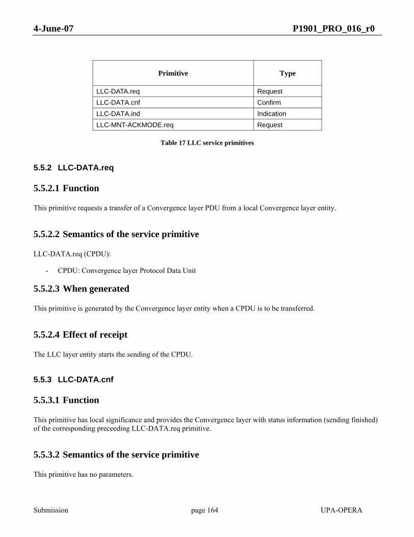
4-June-07 P1901_PRO_016_r0
Submission page 164 UPA-OPERA
Primitive Type
LLC-DATA.req Request LLC-DATA.cnf Confirm LLC-DATA.ind Indication LLC-MNT-ACKMODE.req Request
Table 17 LLC service primitives
5.5.2 LLC-DATA.req
5.5.2.1 Function
This primitive requests a transfer of a Convergence layer PDU from a local Convergence layer entity.
5.5.2.2 Semantics of the service primitive
LLC-DATA.req (CPDU):
- CPDU: Convergence layer Protocol Data Unit
5.5.2.3 When generated
This primitive is generated by the Convergence layer entity when a CPDU is to be transferred.
5.5.2.4 Effect of receipt
The LLC layer entity starts the sending of the CPDU.
5.5.3 LLC-DATA.cnf
5.5.3.1 Function
This primitive has local significance and provides the Convergence layer with status information (sending finished) of the corresponding preceeding LLC-DATA.req primitive.
5.5.3.2 Semantics of the service primitive
This primitive has no parameters.

4-June-07 P1901_PRO_016_r0
Submission page 165 UPA-OPERA
5.5.3.3 When generated
The primitive is passed from the LLC layer entity to the Convergence layer entity to indicate that the previous CPDU has been sent.
5.5.3.4 Effect of receipt
The Convergence layer entity is aware that the LLC is available to send new CPDUs, and can issue new LLC-DATA.req primitives.
5.5.4 LLC-DATA.ind
5.5.4.1 Function
This primitive defines the transfer of a CPDU from the LLC layer entity to the Convergence layer entity.
5.5.4.2 Semantics of the service primitive
LLC-DATA.ind (CPDU):
- CPDU: Convergence layer Protocol Data Unit
5.5.4.3 When generated
The primitive is passed from the LLC layer entity to the Convergence layer entity to indicate the arrival of a CPDU.
5.5.4.4 Effect of receipt
The Convergence layer entity processes the newly received CPDU.
5.5.5 LLC-MNT-ACKMODE.req
5.5.5.1 Function
This primitive requests the use or not of LLC ACKs for data transmission.
5.5.5.2 Semantics of the service primitive
LLC-MNT-ACKMODE.req (ack_mode, port) :
- ack_mode = [yes|no] - port: local transmission port to remote peer node
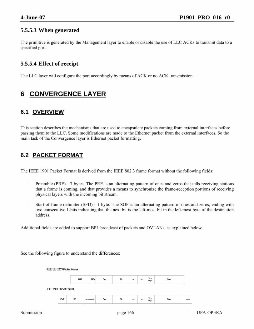
4-June-07 P1901_PRO_016_r0
Submission page 166 UPA-OPERA
5.5.5.3 When generated
The primitive is generated by the Management layer to enable or disable the use of LLC ACKs to transmit data to a specified port.
5.5.5.4 Effect of receipt
The LLC layer will configure the port accordingly by means of ACK or no ACK transmission.
6 CONVERGENCE LAYER
6.1 OVERVIEW
This section describes the mechanisms that are used to encapsulate packets coming from external interfaces before passing them to the LLC. Some modifications are made to the Ethernet packet from the external interfaces. So the main task of the Convergence layer is Ethernet packet formatting.
6.2 PACKET FORMAT
The IEEE 1901 Packet Format is derived from the IEEE 802.3 frame format without the following fields:
- Preamble (PRE) - 7 bytes. The PRE is an alternating pattern of ones and zeros that tells receiving stations that a frame is coming, and that provides a means to synchronize the frame-reception portions of receiving physical layers with the incoming bit stream.
- Start-of-frame delimiter (SFD) - 1 byte. The SOF is an alternating pattern of ones and zeros, ending with two consecutive 1-bits indicating that the next bit is the left-most bit in the left-most byte of the destination address.
Additional fields are added to support BPL broadcast of packets and OVLANs, as explained below
See the following figure to understand the differences:
PRE DA SA TPID TCI Type/length DataSFD
IEEE Std 802.3 Packet Format
DA SA TPID TCI Type/length Data
IEEE 1901 Packet Format
EXT PB OVLAN Word PLW

4-June-07 P1901_PRO_016_r0
Submission page 167 UPA-OPERA
Figure 64 Packet format
The Packet Format has the following fields:
- EXT – 16 bits. Reserved for extensions
- PB – 48 bits. Previous Bridge ID
- OVLAN – 32 bits with the following information:
o PCF – 1 bit. Pre-classified Packet
o PCP – 3 bit. Pre-classified Packet Priority
o OVLANV - 1 bit.Valid OVLAN
o OVLANID - 12 bits. OVLAN Identifier
- DA – 48 bits. Destination MAC Address. The DA field identifies which station(s) should receive the frame.
- SA – 48 bits. Source MAC Address. The SA identifies the sending station.
- TPID – 16 bits. Optional field. Defined value of 8100 in hex. When a frame has the EtherType equal to 8100, this frame carries the tag IEEE 802.1Q/802.1p, otherwise it will be filled with 0x0000.
- TCI – 16 bits. Optional field. VLAN Tag Control Information field including user priority, Canonical format indicator and VLAN ID. This field is always present, even if the TPID is not 0x8100.
- Len – 16 bits. IEEE Std 802.3-style Length/Type Field
- Data – From 42 to 1500 bytes. The Data Payload of this packet.
- PLW – From 0 to 3 bytes. Because the packet has to be 32 bit aligned, there are from 0 to 3 bytes of no valid data at the end of this packet. This field is called Padding Last Word.
The incoming IEEE std 802.3 packet may have TCI field or not, but the TCI field is always present in the IEEE 1901 packet format.
6.2.1 Maximum and Minimum Packet length
The maximum length of one packet is equal to 1536 octets.
The minimum length of one packet is equal to 76 octets.
4-June-07 P1901_PRO_016_r0
Submission page 168 UPA-OPERA
6.2.2 OVLAN Fields
OVLAN fields are intended for OVLAN The OVLAN is a sort of Virtual LAN (VLAN), which functions independtly of IEEE 802.1Q. Jointly with IEEE 802.1Q functionality it provides a two-layer Virtual LAN functionality between BPL nodes. OVLAN functionality is described in Clause 7.4).
The OVLAN fields are the following:
- OVLANV - 1 bit. Valid OVLAN
- OVLANID - 12 bits. OVLAN Identifier
The OVLAN fields have the following meaning:
- When OVLANV is equal to 0, the OVLANID is not used and the packet is not carrying OVLAN information.
- When OVLANV is equal to 1, the OVLANID is equal to the tag, and the tag is used with the same sense as in IEEE 802.1Q. The only difference is the following:
o The tag equal to 0 is a possible tag
o The tag equal to 0xFFF is a tag that must be accepted by all the filters.
As in IEEE 802.1Q where the TCI has priority information, the OVLAN word has two fields to know the priority of this packet:
- PCF: Pre-classified Packet
- PCP: Pre-classified Packet Priority
If PCF is set to 1, the priority of this packet is equal to PCP value. The 802.1p or any other rule is not applied to decide the priority. Priority assignment is described in clause 8.
In the case of nodes that do not perform OVLAN filtering, the OVLAN field will not be modified if the packet was received through a BPL interface. If the packet was received through other interfaces, the node will add the OVLAN fields with OVLANV = 1b0 and PCF = 1b0.
6.2.3 BPL service class
The OVLAN word has two fields that store the poweline service class of this packet. BPL service class is used in parallel to IEEE 802.1Q priority. The fields are:
- PCF: Pre-classified Packet
- PCP: Pre-classified Packet Service class

4-June-07 P1901_PRO_016_r0
Submission page 169 UPA-OPERA
If PCF is set to 1, this indicates that PCP contains a valid BPL service class.
For packets received through a non-BPL interface, PCF = 0. For packets received through a BPL interface PCF must be left unchanged.
BPL service class can be calculated then by the QoS function (see 8.2).
6.2.4 PB Field
This field are used to avoid loops with broadcast packets.
Broadcast packets can be sent in two ways through the BPL network:
- Using the broadcast port. The broadcast packet is sent using the broadcast port and all nodes that have negotiated ports with the sender will receive it.
- Using unicast ports. The broadcast packet is sent once per each negotiated port, except the port where it was received in the case it was a BPL port.
In the case when a broadcast packet is sent using the broadcast port, these fields are used to avoid loops. In the other case, they are not necessary. In any case, they shall always be present in all packets.
The meaning of the field (defined in 6.2) is the following:
- PB: Previous Bridge ID. It shall contain the MAC address of the previous node that has transmitted this packet.
When a packet enters the BPL network Previous Bridge ID shall be set to 0.
In any retransmission, the Previous Bridge ID shall be filled with the ID of the last unit that transmitted the packet.
When receiving a packet it shall be discarded when its Previous Bridge ID is equal to the MAC address of the node that has received the packet, because this indicates that the node has already received the packet before..
6.2.5 Octet alignment
The bytes from IEEE Std 802.3 are stored in 32 bits words in the following way:
Byte 3
Byte 2
Byte 1
Byte 0
Figure 65 Byte order

4-June-07 P1901_PRO_016_r0
Submission page 170 UPA-OPERA
From IEEE 802.3 interface, the bytes are received in the following order: byte0, byte1, byte2 and byte3.
And from this 32 bits word, the bytes are transmitted into the LLC interface in the following order: byte3, byte2, byte1, byte0. The packets are transmitted to the LLC in the way shown in Figure 66, starting from the top, since the LLC works with bytes.
If we define N as the number of bytes in Data Payload plus the number of bytes of the Length/Type Field, then we can write N = 4*m + p; with m an integer value and p equal to 0, 1, 2 or 3. The number of bytes in PLW is equal to 0 if p is equal to 0 or 4-p in the other cases, because the packet is 32 bit aligned.

4-June-07 P1901_PRO_016_r0
Submission page 171 UPA-OPERA
Octet
13
Data (from byte [6] to [4*m – 3])
PLW (0 bytes if p is equal to 0 OR (4-p) bytes if p is different from 0)
0123457 6
14
15
16
Reserved
PCP PCFReserved
OVLANV OVLANID[11:8]Reserved
OVLANID[7:0]
PB[1]
PB[0]
Extensions[1]
Extensions[0]
PB[5]
PB[4]
PB[3]
PB[2]
1
2
3
4
5
6
7
8
9
10
11
12
DA[3]
DA[2]
DA[1]
DA[0]
SA[1]
SA[0]
DA[5]
DA[4]
SA[5]
SA[4]
SA[3]
SA[2]
17
18
19
20
21
22
23
24
25
26
27
28
TCI[7:0]
TCI[15:8]
29
30
TPID[7:0]
TPID[15:8]
31
32
Data[1]
Data[0]
33
34
bits
Lenght[0]
Length[1]
35
36
Last Word Data (from byte [4*m-2] to [4*m+p-3])
Data[5]
Data[4]
37
38
Data[3]
Data[2]
39
40
FCS[3]
FCS[2]
FCS[1]
FCS[0]
41
42
43
44
Figure 66 Packet byte order to the LLC
6.3 CONVERGENCE LAYER SERVICE PRIMITIVES
The bridging block communicates with the convergence layer through 3 service primitives Eth.req, Eth.cnf and Eth.ind:

4-June-07 P1901_PRO_016_r0
Submission page 172 UPA-OPERA
• Eth.req (802.3/EthernetII frame, BPL local ports list, PB, OVLAN word): This primitive requests the transfer of an Ethernet frame from the local bridging block to a single peer bridging block or multiple peer bridging blocks in the case of multi-port transfer requests (see 6.3.1).
• Eth.ind (802.3/EthernetII frame, BPL local port, LB, OVLAN word, Session ID): This primitive defines the transfer of an Ethernet frame from the convergence layer to the bridging block.
• Eth.cnf: This primitive is used by the convergence layer to notify the bridging block of the results of the Eth.req primitive.
Notes:
• VLAN tag may be included in the 802.3/EthernetII frame
• The OVLAN word includes PCF, PCP, OVLANV and OVLANID
6.3.1 Multi-port transfer requests
Multi-port transfer requests correspond to Eth.req service primitives including several BPL local ports as argument. Such requests are inherent to bridging in TDRs and HEs which manage several BPL ports. The multi-port requests are solicited by standard transparent bridging actions such as:
1. Broadcast transmission: The IEEE 802.3 frame includes a Broadcast Ethernet address in its Destination Address field. The multi-port request concerns all the BPL ports managed by the bridging function except the one from which the Ethernet frame was received (if it was eventually received from a BPL port).
2. Multicast transmission: The IEEE 802.3 frame includes a Multicast Ethernet address in its Destination Address field. The multi-port request might concern a subset of the BPL ports managed by the bridging function or a single native multicast BPL port associated.
3. Bridge flooding: The bridging block could not find any association of a unicast Ethernet Destination addresses with a specific bridge port, the request is then flooded to all the bridge ports. The multi-port request concerns all the BPL ports managed by the bridging function.
6.4 BROADCAST/MULTICAST HANDLER FUNCTIONAL REQUIREMENTS
The convergence layer shall include a broadcast/multicast handler that shall perform the following functions:
1. Handling transfer of multicast management messages: Management messages can be unicast or multicast as described in section 7.4. Multicast management messages can be received from the bridging fundtion through primitives which are either single port requests or multi-port requests. Any multicast management message received through these requests shall be transferred over the broadcast port using HURTO modulation.
2. Management of multi-port transfer requests which do not carry multicast management messages: upon reception of such multi-port transfer request from the convergence layer, the block shall compute the best method for handling the transfer. If the multi-port request concerns all the local ports of the Port Solver Table or if the request includes a broadcast/multicast Ethernet Destination Address, depending on the bit-loading tables associated to each local port, the block might consider transferring the Ethernet frame over the broadcast local
4-June-07 P1901_PRO_016_r0
Submission page 173 UPA-OPERA
port using HURTO modulation. In the other cases, the multi-port request will result in several consecutive LLC service requests related to each unicast local port, or in the use of a native multicast local port.
3. Broadcasts loop back avoidance: on the reception path, upon reception of a packet over the broadcast local port (127), the module shall discard any packet which is detected as previously transmitted (that is, the MAC address contained in the PB field of the packet is equal to the MAC address of the node).
4. On the reception path, upon reception of a packet over the broadcast local port (127), the local port passed within the Eth.ind primitive shall be the one assigned to the remote node from which the request was received.
7 BRIDGING FUNCTION
7.1 General
The bridging function interconnects bridge ports. There are two types of bridge ports: BPL ports and non-BPL ports and the management port. BPL ports are the bridge ports that represent a remote PL unit and are directly mapped onto the completed entries of the Port Solver Table. Non-BPL ports are any other external ports of the unit (e.g. Ethernet, USB, WIFI,…).
The bridging function is based in standards IEEE 802.1D and IEEE 802.1Q as described below.
From a bridging standpoint, the convergence layer is seen as a set of bridge ports called “BPL ports” which are both transmission and reception unicast and native multicast ports. The bridging block of a node handles as many BPL unicast ports as there completed entries in the Port Solver Table of this node, in addition to the native multicast ports that has a valid value in such Port Solver Table. The identifier of a BPL port corresponds to the value of the local port attached to a remote node, that can be a native multicast or an unicast port. The status (open/close) and the identifier of the BPL ports are mapped onto the status and identifiers of the local ports defined in the Port Solver Table.
There is also a BPL management entity that can access all the ports in the same conditions as the higher layer entities as described in IEEE 802.1D.
*Note: The port solver table includes complete entries and incomplete entries. Complete entries correspond to local port which are associated to solved remote port and MAC addresses. Incomplete entries correspond to local ports which associated unicast remote port are still not solved via the Port Solver Protocol.A complete entry may have an additional native multicast remote port associated.
7.2 IEEE 802.1D conformance
The bridging function shall conform to:
a) IEEE Std 802.1D, with Basic Filtering Services support requirements

4-June-07 P1901_PRO_016_r0
Submission page 174 UPA-OPERA
b) IEEE Std 802.1D Management (clause 14 of IEEE 802.1D-2004) requirements
c) IEEE Std 802.1D Remote Management (clause 5.2 of IEEE 802.1D-2004) requirements
as modified by the provisions of this standard
The permanent filtering database, as defined in IEEE 802.1D-2004 clause 7.9 shall have a minimum size of 8 entries.
The dynamic filtering database, as defined in IEEE 802.1D-2004 clause 7.9 shall have a minimum size of 64 entries.
7.3 IEEE 802.1Q conformance
The bridging function shall support VLAN according to IEEE Std 802.1Q requirements for VLAN-aware bridges, as modified by the provisions of this standard.
The bridging function shall support a minimum of 32 VLANs.
7.4 OVLAN Function
7.4.1 General
The OVLAN functionality is based on IEEE 802.1Q Virtual LAN (VLAN), but does not substitute the IEEE 802.1Q functionality. Instead, if enabled, it shall work independtly of IEEE 802.1Q functionality.
OVLAN function is is aimed to:
• Avoid packets from one customer leaking into a neighbor customer (for security reasons).
• Avoid packets from one BPL sub-network (for example, an LV cell) leaking into another BPL sub-network (for security reasons and in order to avoid the problem of bridge tables filling up with unnecessary MAC addresses).
In such cases, as IEEE 802.1Q VIDs are limited to less than 4096, a large network can rapidly run out of VLANs numbers if they are used for customer isolation, OVLAN should be used, leaving IEEE 802.1Q for its traditional VLAN purposes.
The following processes are defined for OVLAN function
4-June-07 P1901_PRO_016_r0
Submission page 175 UPA-OPERA
a) Frame admittance and OVLAN assignment
b) OVLAN Ingress filtering
c) OVLAN Egress filtering
Each PL port has a list of OVLAN IDs which represent the OVLANS to which the port belongs (OVLAN_list)
7.4.2 Frame admittance and OVLAN assignment
7.4.2.1 Non PL ports
The OVLAN parameters of a non PL port are:
- OVLAN enabled / disabled - POVID (Port OVLAN identifier)
If one port is OVLAN enabled, all incoming frames are assigned an OVLAN ID which is exactly the POVID of such port.
7.4.2.2 PL PORTS
The OVLAN parameters of a pl port are:
- OVLAN enabled / disabled
- Tagged only
- POVID (Port OVLAN identifier)
All packets coming from a port are discarded if and only if:
a) The OVLAN is enabled for such port , tagged only parameter is set and the frame does not carry a valid OVLAN ID.
The OVLAN ID of a frame is assigned the value of the POVID of the port if and only if:
b) The OVLAN is enabled, tagged only parameter is not set and the frame does not carry a valid OVLAN ID.
In the rest of cases the frames are admitted unchanged.

4-June-07 P1901_PRO_016_r0
Submission page 176 UPA-OPERA
7.4.3 OVLAN Ingress filtering
If any frame coming into the bridge has a valid OVLAN identifier, OVLAN is enabled and its OVLAN identifier is not included in the OVLAN list for such port, the frame is discarded, unless the frame has FFF as identifier. It is passed otherwise.
7.4.4 OVLAN Egress filtering
If any frame going out of the bridge has a valid OVLAN identifier and this OVLAN identifier is not included the OVLAN list for such port, the frame is discarded, unless the frame has FFF as identifier. It is passed otherwise.
7.4.5 OVLAN management
If a unit has OVLAN functionality, OVLAN parameters per port (OVLAN enabled / disabled, tagged only, POVID, and OVLAN_list) shall be modifiable by a management process.
The management process shall be executable remotely.
7.5 Sending broadcast/multicast Ethernet frames
When sending a broadcast/multicast Ethernet frame or when flooding the ports of the bridge, two main ways to transmit multicast IEEE 802.3 frame con be configured.
In the first option the bridging function shall provide the list of BPL ports related to this transfer as part of the Eth.req service primitive
In the second option, the bridging function shall provide a native multicast BPL port related to this transfer as part of the Eth.req service primitive.
The bridging function shall also support management of associations of multicast groups to native ports.
The association of a multicast group to a native multicast port is done in two stages:
a) The remote nodes belonging to a multicast group are associated to the native multicast port
For this, the unit shall send Port Solver Protocol Multicast Port packets to the nodes selected to become associated to the native multicast port. The aim of such packets is to add in the Port Solver Table of each destination node that wants to join the multicast flow the selected Local native multicast Port as Second Remote Port (RP2).
4-June-07 P1901_PRO_016_r0
Submission page 177 UPA-OPERA
b) In the forwarding tables, the list of individual unicast ports associated to the multicast group is substituted by the native multicast port.
If a multicast group is associated to a native multicast port, any incorporation of a new node to such multicast group shall result in an association of such node to the native multicast port, as described in (a).
Conversely, if a node is removed from a multicast group and such multicast group is associated to a native multicast port, the node shall be removed from the associated native multicast port. This shall be done by sending a Port Solver Protocol Multicast Port carrying as local native multicast port the so called invalid port. (0xFF).
These actions (adding or removing a node from a native multicast port, and incorporation of the native multicast ports to the forwarding tables) shall be supported as a result of a management action and may, optionally, be done as a consequence of operation of group management protocols, such as IGMP or GMRP.
7.6 PB field
7.6.1 Bridging between BPL ports
When bridging between BPL ports (HE or TDR feature), the bridging function shall return within the Eth.req a PB argument equal to the ID from which the packet has been received.
7.6.2 Bridging from a non-BPL port to a BPL port
When bridging from a non BPL-port to a BPL port, the PB argument of the Eth.req shall be set to 0.
7.7 BPL service class transmission
When bridging between BPL ports , if PCF=1 within the OVLAN argument of the received Eth.ind, the PCF and PCP values (subfield of the OVLAN word argument) included in the subsequent Eth.req shall be kept unchanged.
7.8 Filtering multicast management messages from a BPL port
BPL Management messages are IEEE 802.2 SNAP encapsulated data units carried over an Ethernet frame which can be either unicast or multicast. Multicast management messages make use of one of the two following multicast addresses (referred as management multicast addresses): the STP multicast address 0x0180C2000000 (primarily used by the STP protocol but also used for some BPL management messages) or the IEEE P1901 specific multicast address: 0x01139D000000. Any Ethernet frame including a management multicast address shall be filtered by the bridging function and not retransmitted to any other port. Upon reception of management messages destined to the above two mentioned multicast addresses, the bridging function shall provide these frames to the management port.

4-June-07 P1901_PRO_016_r0
Submission page 178 UPA-OPERA
7.9 Filtering multicast management messages from the management port
BPL Multicast management messages from the management port shall only be flooded to the BPL ports (non-BPL ports excluded).
8 QOS SERVICES
8.1 INTRODUCTION
This section describes mechanisms for applying specific guarantees in terms of bandwidth, latency and reliability to some flows. It is also possible to define a policy upon congestion. Any flow requiring such guarantees must initiate a connection through a Connection Admission Control procedure using protocol described in 0.
The mechanisms described here below are designed for flows circulating from the HE to a CPE or vice versa. These mechanisms have not been designed to support QoS for flows between CPEs,
The QOS services described here below rely on the configuration of several components:
1. Service classes. (Must be declared in all the masters of a BPL cell).
2. Classifier module: this module maps flows onto service classes (preconfigured in all the nodes).
3. Congestion management (declared in all the masters).
4. Traffic specifications, published through the CAC procedure. Pre-determined traffic specifications must be declared in CPEs.
Note: A flow is a unidirectional data stream exchanged between two BPL units and carried over the same service class.
BPL network uses a shared medium and provides differentiated control of the medium to handle data transfers with QoS requirements. QoS services carry out end-to-end traffic delivery providing QoS transport on a per-user basis.
The BPL cell master node will be in charge of schedule and guarantee the QoS of the BPL cell, and must assign resources to cell nodes based on the configured bandwidth limit and the resources reservations requests made. This node shall be named QC (quality controller).
Also, there are others figures in the BPL cell which are the Flow Master Nodes (FMNs). A FMN is defined as the BPL node in charge of guarantee QoS requirement for a registered flow. This node will be the QC and also can be the BPL repeaters which will distribute the resouces given by the QC to the nodes connected to it.

4-June-07 P1901_PRO_016_r0
Submission page 179 UPA-OPERA
The FMN must receive the resource reservations requests using the CAC protocol (See section 0) and must decide if it has enough resources to assign to the incoming request or if it has to request more resources to the BPL master node.
With this mechanism, we will have a complementary tool to limit the bandwidth. This information will be interesting to known if a new traffic of a service class can be started and the requirements for that traffic and service class can be assured.
8.2 SERVICE CLASS DEFINITION
Up to eight service classes can be defined within a BPL cell. Services classes are globally defined over a BPL subcell. Four service parameters are necessary to fully describe a service class: priority, subcell_access_time, resource reservation type and service reliability.
8.2.1 Priority
Service classes are directly mapped onto priorities. A priority uniquely identifies a service class. That is why all the other service parameters are configured and mapped from this priority parameter. Priorities shall have values from 0 to 7, 0 being the lowest priority. If packets have to be dropped at the transmitter because of lack of resources, then the lower priority packets shall be dropped before the higher priority packets. When there are data of different priorities addressed to the same destination, higher priority data shall be transmitted earlier than lower priority data.
8.2.1.1 Configuration
Priority parameter is determined by the Classifier module operating at the bridging block level. The classifier analyses all the frames received from a bridge port (BPL port, non-BPL port, management port) and assigns a priority to each Ethernet frame transmitted to the convergence layer via the Eth.req primitive (see 6.3). The Classifier operates according to some predetermined and/or configurable rules (see 11.4). Any frame received from the management port shall be mapped to priority 7 (that is: service class 7).
Note: For each Eth.req primitives delivered by the bridging block, a priority is submitted as part of the OVLAN word argument (PCP bits). The PCF bit of this OVLAN word might be set to 1 meaning that the priority is to be seamlessly bridged through the intermediate nodes of the BPL cell. This priority information is summarized within the Priority field of any Burst Header and the Frame Priority field of every upstream data token.
8.2.2 Max Subcell Access Time
The Max_Subcell_Access_Time corresponds to the max duration for a flow to access the channel on the subcell level. It is a latency requirement for the scheduler to be configured within any master of a BPL cell.
Four Max_Subcell_Access_Time are defined at the master level. The minimum value of the Max_Subcell_Access_Time is used as the reference step from which the three other Max_Subcell_Access_Time are derived by multiplying by 2, 4 or 8 this reference step.
4-June-07 P1901_PRO_016_r0
Submission page 180 UPA-OPERA
8.2.2.1 Configuration
The reference step shall be configured within any master of a BPL cell. This parameter is configured using the QOS_LATENCY_STEP parameter (min 20ms, max 400ms).
Mapping a Max_Subcell_Access_Time to a priority: Such a mapping shall be declared within each master by using the QOS_LATENCY.prio+1 parameter.
8.2.3 Resource reservation type
This parameter is related to the type of claimed guarantees provided in terms of node resources and time resources.
It can take three values:
• Type Best Effort: No guarantees on the node and time resources. This type will be mapped with the non-guaranteed service classes. Resources are granted on a Best Effort basis.
• Type ABR (Available Bit-Rate): Requests ask for node and time resources for which a minimum bandwidth can be guaranteed with a peak over the minimum. The peak can be limited by the network capability or the node limit bandwidth.
• Type VBR (Variable Bit-Rate):Requests ask for node and time resources for which an average bandwidth can be guaranteed with a maximum variation around this average.
• Type CBR (Constant Bit-Rate):Requests ask for individual guarantees in terms of node and time resources. The granted node and time resources are not shared. The claimed bandwidth is guaranteed.
Note: Any class which is associated to an ABR, VBR or CBR type corresponds to a connected service requiring initiation of a Connection Admission Control Procedure. By extension, CBR, VBR or ABR flows are called connected flows unlike Best Effort flows which are non connected flows.
A maximum upstream and downstream bandwidth limitation applies to all the Best Effort and ABR flows of the same node (see 12).
CBR and VBR traffic shall be reserved for operator services such as VoIP and video streaming services (IPTV, VOD, …), and shall be out of the bandwidth limitation. To accept or deny these services, the FMN must assure that network resources will be available and mechanisms for AAA services shall be used in order to authenticate the service can be used by the node.
8.2.3.1 Configuration
Mapping a Resource Reservation Type to a priority: Such a mapping shall be declared within each master by using the QOS_PRIORSV.prio+1 parameter.

4-June-07 P1901_PRO_016_r0
Submission page 181 UPA-OPERA
8.2.4 Service reliability
This parameter defines if the ACK mode is enabled (see section 5.4) within the service class.
8.2.4.1 Configuration
Mapping Service Reliability to a priority: Such a mapping shall be declared within each master by using the QOS_PRIOACK.prio+1 parameter.
8.2.5 Example of a service class definition
The service class definition shall be the same for all nodes in the BPL cell, and must determine univocally the the relationship between priority, maximum subcell access time, resource reservation and service reliability characteristics.
This service class definition must be used by QoS to determine the priorization between flows and resources reservation in the network, and will provide criteria to allow or deny new flows or to drop existent flows to allow new flows which higher service class.
Table 18 shows an example of possible relationship between service classes, priorities, Max_Subcell_Access_Time, Service Reliability and Resource Reservation Type.

4-June-07 P1901_PRO_016_r0
Submission page 182 UPA-OPERA
Service Class
Resource reservation
Priority MaxSubcell Access Time
Service Reliability (ACK enabled)
7 Best Effort 7 240 No
6 CBR 6 30 No
5 VBR 5 60 Yes
4 VBR 4 120 Yes
3 VBR 3 120 No
2 ABR 2 120 Yes
1 Best Effort 1 240 No
0 Best Effort 0 240 No
Table 18 Definition of Service Classes: example
The definition of service classes as described in table 1 could be used to implement QoS services for applications as described in Table 19.

4-June-07 P1901_PRO_016_r0
Submission page 183 UPA-OPERA
Service Class Application Examples
7 Management messages
6 VoIP
5 Video, Games
4 Data Highprio
3 Data Highprio
2 Data Highprio
1 Data Lowprio
0 Data Lowprio
Table 19 Mapping applications to service classes: example
8.2.6 Provisioning Service Class Definitions to slaves
As detailed in 0, nodes that wish to request a resource reservation through the Connection Admission Control procedure must make a reference to the requested service class. As a matter of fact, it is necessary for the slaves to have an idea of the service class definitions. The description of the available service classes will be obtained through the Autoconfiguration process.
8.3 CONGESTION MANAGEMENT
The mission of CM is to manage the accepted connections in congested networks (due to a sudden drop in the channel quality, for example). There are two possible policies that can be configured in the system:
• Fair Congestion Management Policy (FCMP): all traffic flows are treated equally. Therefore, if the traffic scheduler cannot meet the bandwidth and latency requirements from users, it will decrease the performance of all active flows equally until new bandwidth and latency definitions can be supported.

4-June-07 P1901_PRO_016_r0
Submission page 184 UPA-OPERA
• Priority Congestion Management Policy (PCMP): lower priority traffic performance is decreased in order to guarantee higher priority traffic SLA. Therefore, access to the channel is denied to lower service types first, until SLA of higher service types can be maintained.
• “Quality Service” Congestion Management Policy (QSCMP): The congestion manager will act like as Priority Congestion Management but uses the service class and the quality session parameters to perform the scheduling and the acceptance criteria for new sessions. The sessions with higher quality session values will have more probabilities to be scheduled accomplishing its requirements when network is congested. Quality Session parameter can be also a mixture of priority and age, or an arbitrary parameter defined by the network operator.
8.3.1 Configuration
The Congestion Management can be configured using the Auto-configuration protocol. In this section, we enumerate the auto-configuration parameters that modify the behavior of the Congestion Management. For more information, see 11.
QOS_BW_POLICY = [0|1|2] configures the CM in which the QoS manages the network in the event of congestion (0 configures the CM in FCMP mode; 1 configures the CM in PCMP mode; 2 configures the CM in QSCMP mode).
8.4 CONNECTION ADMISSION CONTROL
Initiation of a Connection Admission Control (CAC) procedure is required for any connected flow. The mission of the Connection Admission Control is to ensure that the BPL network can deliver the agreed services and guarantees to new flows while maintaining the requested performance of already accepted flows.
The Connection Admission Control functionality is embedded inall the network. The CAC protocol might be used in the following two scenarios:
• Before the transmission of a connected flow, the CAC shall be used to reserve resources on the nodes in the system that collaborates in the communication of the new flow (from the node initiating the flow to the nodethat shall guarantee the flow). The CAC requests made to commit resources for a given Service Class may be new or updates from previous reservations.
• At the end of the transmission of a connected flow, resources may be released. Release of resources may be done explicitly by transmitting a CAC Stop message indicating traffic flow is not longer needed, or may be done when a timer, MAX_CAC_DRP_TO expires since the last time a Data Token with the Session ID of the traffic was received by the node.
In the CAC protocol, the exchanged parameters to verify whether or not the BPL network can guarantee the required service shall include the required bandwidth, and the maximum latency demanded by the new node.
4-June-07 P1901_PRO_016_r0
Submission page 185 UPA-OPERA
8.5 Traffic Shaping
QoS apply traffic shaping in two different ways. Each one is applied based on the service class of traffic:
• Limit bandwidth: Is applied for best-effort and ABR service classes. Is based on the credit assignation for this service classes. This credit is assigned per-user and is renewed periodically. If the credit is not used during the period time, it’s lost and can not be used in the next period.
• Guaranteed bandwidth: Is applied for VBR and CBR service classes. Traffic must be allowed prior to transmit and a reservation is made for this type of traffic using the CAC protocol. Channel time is assigned based on the resources reservation to meet bandwidth and latency requirements. Due to the explicit reservation of resources, nodes shall have mechanisms to allocate buffer space to support the incoming traffic.
8.5.1 QOS Requirements
To provide QoS requirements is needed support from MAC layer in order to identify the network usage by each node and the traffic service classes in the network. This support must be provided as MAC primitives and will be:
• Transmitted priorities by a CPE. Must be a set of bits and each bit must be mapped to a priority
• Transmitted priorities by BPL subcell/cell masters.
• Single transmission Channel time: Must be the transmission time used for individual transmissions for each node in the BPL cell.
• Transmitted data: Data transmitted since last time the token was received, so that bandwidth limitation algorithm can be reconfigured dynamically.
• Unused channel time: The percentage of network resources assigned to this node available in the network.
Other QoS facilities should be implemented in order to guarantee QoS requirements:
• BPL node shall be able to define service classes with or without MAC Level acknowledgment capabilities.
• BPL node shall be able to assign resources in a per-user and per-service basis to guarantee constant, variable or peak rate traffic requirements.
• BPL node shall be able to transmit to a subset of possible receivers nodes in order to guarantee unique channel usage per-user.
• BPL node shall configure MTU per-user in order to guarantee minimum transmission time per-user.
• BPL node should be able to avoid transmission of lower priorities to guarantee preferential treatment of higher priorities in a per-flow basis.

4-June-07 P1901_PRO_016_r0
Submission page 186 UPA-OPERA
Furthermore, there are MAC primitives to give the QoS scheduler an idea of the BPL topology. These primitives collect information in the Upstream direction. These primitives allows to compute correctly the Validity field. These parameters are:
• Maximum Number of Hops in the network
• Number of Downstream Nodes
9 LAYER MANAGEMENT
9.1 CONTROL PROTOCOLS
9.1.1 CCP (Communication Control Protocol) Description
The exchange of management messages between IEEE P1901 nodes needs a special and homogeneous structure in order to simplify implementation and clarify information exchanges between nodes. Such information will have as source and destination IEEE P1901 nodes, and will be used for internal management.
The structure of the packet that will be exchanged by two BPL nodes will follow the scheme presented in Figure 67:
Dest MAC Src MAC Payload
DS
AP
SS
AP
Data
CT
LO
UI0
Typ
e0
Leng
th
OU
I1O
UI2
Typ
e1
TP
ID
TC
I
Figure 67 Management packet
The management information will be encapsulated using SNAP as depicted in Figure 67 into a regular Ethernet Frame. Using SNAP with an assigned OUI, it is possible to create specific protocols for IEEE P1901 nodes.
Encapsulated fields will be described in the following table:
Field Length Description
DSAP 1 byte Destination Service Access Point
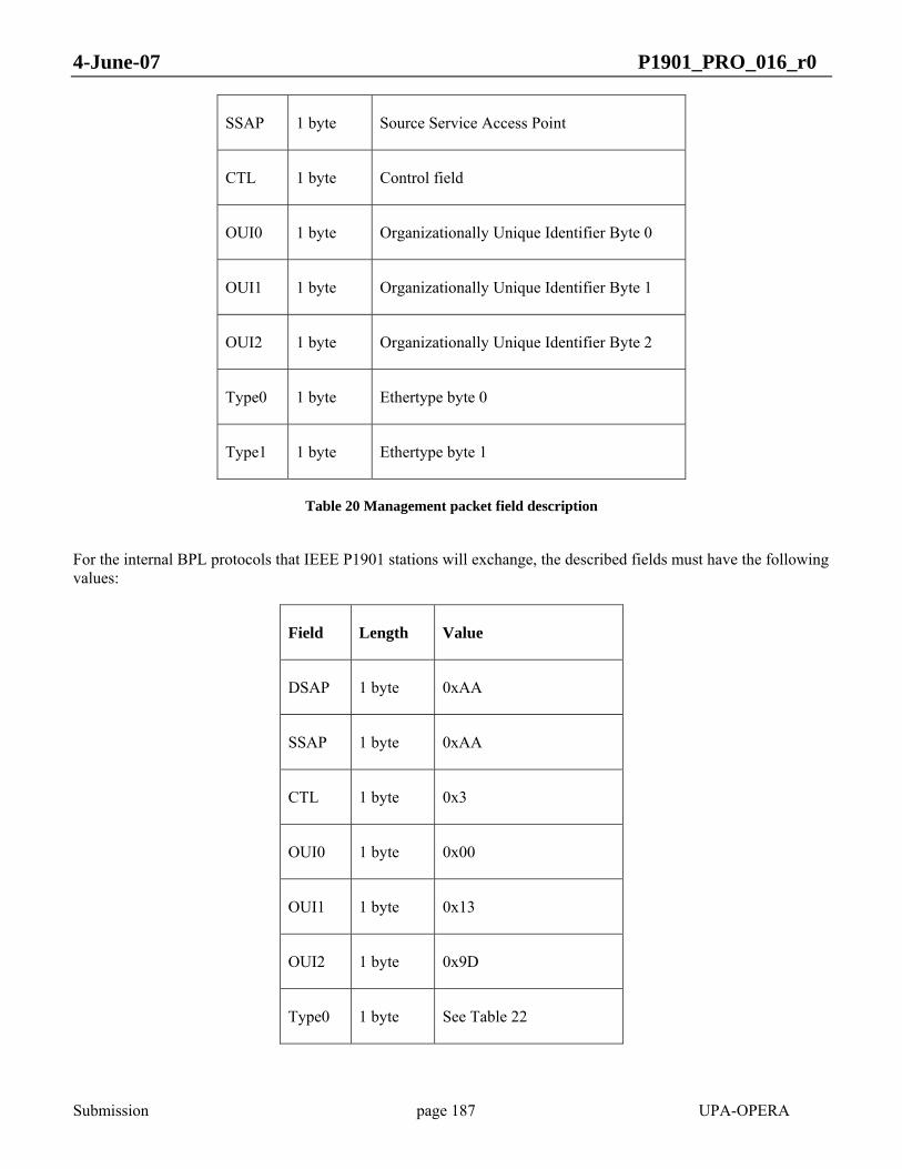
4-June-07 P1901_PRO_016_r0
Submission page 187 UPA-OPERA
SSAP 1 byte Source Service Access Point
CTL 1 byte Control field
OUI0 1 byte Organizationally Unique Identifier Byte 0
OUI1 1 byte Organizationally Unique Identifier Byte 1
OUI2 1 byte Organizationally Unique Identifier Byte 2
Type0 1 byte Ethertype byte 0
Type1 1 byte Ethertype byte 1
Table 20 Management packet field description
For the internal BPL protocols that IEEE P1901 stations will exchange, the described fields must have the following values:
Field Length Value
DSAP 1 byte 0xAA
SSAP 1 byte 0xAA
CTL 1 byte 0x3
OUI0 1 byte 0x00
OUI1 1 byte 0x13
OUI2 1 byte 0x9D
Type0 1 byte See Table 22

4-June-07 P1901_PRO_016_r0
Submission page 188 UPA-OPERA
Type1 1 byte See Table 22
Table 21 Management packet field values
Table 22 includes the used types and subtypes for mandatory BPL protocols. Description of each one will be provided in the following sections. In general, with Type0 a Specific protocol is set and with Type1 a message type that makes sense into the protocol is announced. In the following table, messages of each BPL protocol are described, providing information about the content of each type field for each message.
Type0 Protocol Type1 Description
0x06 Adaptive Bit-Loading Protocol 0x01 BPC
0x07 Port Solver Protocol 0x01 Access message
0x02 Anounce Message
0x03 Multicast message
0x04 Multicast ACK message
0x0b Access Protocol 0x01 Petition Status
P Sub_Type P.(1 bit) is the most significant bit of Type1.
Sub_Type (7 bits)
0 0x01 Resources Reservation Request
0 0x02 Resources Reservation Reply
0x05 Connection Admission Control Protocol
0 0x03 Resources Reservation Change

4-June-07 P1901_PRO_016_r0
Submission page 189 UPA-OPERA
0 0x04 Resources Reservation Change Confirmation.
0 0x05 Resources Reservation Dropped
0 0x06 Resources Reservation stop
0x07 Parametric Translation Table protocol
See 12.2.5
0x0a Cluster Discovery Protocol 0x01 CDP message
0x0b Automatic management of crosstalks 0x01 IDP
0x02 BNDP
0x03 BNDA
Table 22 Management packet protocol types
In some cases it is foreseen that the management information that has to be sent may not fit in one single packet. A mechanism is provided to split the information in several packets using sub-tables. The general format of those packets follows in Table 23:
Bytes Fields Length
0 Sub-table number 1 bytes
1 Number of sub-tables 1 bytes
2 Number of entries of the sub-table 1 byte
3 - 8 Sender MAC address 6 byte
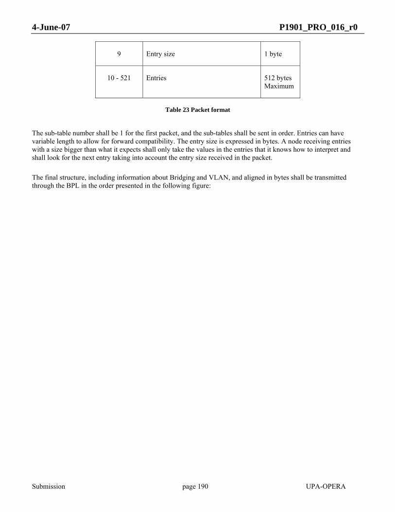
4-June-07 P1901_PRO_016_r0
Submission page 190 UPA-OPERA
9 Entry size 1 byte
10 - 521 Entries 512 bytes Maximum
Table 23 Packet format
The sub-table number shall be 1 for the first packet, and the sub-tables shall be sent in order. Entries can have variable length to allow for forward compatibility. The entry size is expressed in bytes. A node receiving entries with a size bigger than what it expects shall only take the values in the entries that it knows how to interpret and shall look for the next entry taking into account the entry size received in the packet.
The final structure, including information about Bridging and VLAN, and aligned in bytes shall be transmitted through the BPL in the order presented in the following figure:

4-June-07 P1901_PRO_016_r0
Submission page 191 UPA-OPERA
Octet
13
Data from byte 2 to N
PLW
0123457 6
14
15
16Reserved
PCP PCFReserved
OVLANV OVLANID[11:8]Reserved
OVLANID[7:0]
LB[3]
LB[2]
LB[1]
LB[0]
PB[1]
PB[0]
LB[5]
LB[4]
PB[5]
PB[4]
PB[3]
PB[2]
1
2
3
4
5
6
7
8
9
10
11
12
DA[3]
DA[2]
DA[1]
DA[0]
SA[1]
SA[0]
DA[5]
DA[4]
SA[5]
SA[4]
SA[3]
SA[2]
17
18
19
20
21
22
23
24
25
26
27
28
TCI[7:0]
TCI[15:8]
29
30
TPID[7:0]
TPID[15:8]
31
32
SSAP
DSAP
33
34
bits
Lenght[1]
Length[0]
35
36
OUI[2]
OUI[1]
37
38
OUI[0]
CTL
39
40
TYPE1
TYPE0
43
44
Data[1]
Data[0]
41
42
Figure 68 Management packet structure
When VLANs are active, all CCP packets must use the power-line reserved VLAN tag 1.
Other standard protocols like spanning tree, will follow the IEEE 802 standard.
4-June-07 P1901_PRO_016_r0
Submission page 192 UPA-OPERA
9.1.2 Adaptive Bit-Loading Protocol (ABLP)
9.1.2.1 Overview
The Adaptive Bit-Loading Protocol (ABLP) is responsible for the interchange of tonemap information between the different nodes of an established BPL network.
Tonemap negotiation is unidirectional and needs direct visibility between the involved nodes. One node sends the tonemap configuration and the other accepts it. The same tonemap shall be used by receiver nodes in order to understand the received data.
A pair of nodes can establish two different logical links identified in the reception side by the pair transmitter’s MAC and First Remote Port (RP1) and transmitter’s MAC and Second Remote Port (RP2). The link determined by the transmitter’s MAC and the Second Remote Port is usually devoted to Multicast Transmissions, and may have a different tonemap from the link determined by the pair transmitter‘s MAC and First Remote Port (RP1) (See 9.1.2.1). In this case, the negotiation will be independent for each one of the links.
Tonemap negotiation includes:
- The tonemap. - The tonemap ID (TMI) associated to the included tonemap. - And, optionally, cycle selection (CS) configuration.
Cycle selection configuration can be included to indicate that current tonemap has been designated to be used only during a specific part of the cycle defined as a multiple of Qs (See 4.4.2.10). In that case, nodes will need to negotiate several tonemaps to cover the the entire cycle.
9.1.2.2 Protocol
The ABLP defines two different packets:
- The ABLP Tonemap information packet (ABLP_inf). - And the ABLP Tonemap acknowledgement packet (ABLP_ack).
The ABLP_ack is used by the ABLP_inf packet transmitter to know if the tonemap configuration has been received and accepted by the transmitter node. In case that acknowledgment does not arrive, the ABLP_inf packet transmitter shall send a new ABLP_inf packet. The ABLP_inf packet transmitter shall start a timer after the transmission of the packet.
The loss of an ABLP_inf packet or the ABLP_ack packet shall not cause a tonemap mismatch (different tonemaps with the same TMI in transmitter and receiver). Current tonemaps shall not share TMI with new tonemaps and shall not be immediately discarded after sending the new packet. The loss of an ABLP_inf packet will imply the use of previous tonemap configuration and the transmission of a new ABLP_inf packet.
On the other hand, although the ABLP_ack packet is lost, the new tonemap configuration can be used. However, a new ABLP_inf packet shall be sent (timeout) with the objective of finishing the negotiation.

4-June-07 P1901_PRO_016_r0
Submission page 193 UPA-OPERA
The ABLP_ack packet shall include the same TMI and sequence number as the transmitted ABLP_inf packet. The sequence number shall be increased with every transmitted ABLP_inf packet. The reception of the ABLP_ack implies that the receiver has accepted the new tonemap configuration.
Figure 69: Example of successful tonemap negotiation
9.1.2.3 ABLP_inf packet format
ABLP_inf packets shall be sent in HURTO mapping mode. The use of a different mapping could result in the impossibility to negotiate new tonemaps if current tonemap configuration is inadequate.
ABLP_inf packets use the CCP with Type0 0x01 and Type1 0x01. The packet format can be seen in Figure 70.
Figure 70: ABLP_inf packet
ABLP_inf packets use 0x01139D000000 multicast address as destination MAC address.

4-June-07 P1901_PRO_016_r0
Submission page 194 UPA-OPERA
Source MAC address is set to the ABLP_inf packet transmitter node MAC address. The ABLP_inf data is shown in Figure 71.
Figure 71: ABLP_inf Data
Description:
a) Remote Port: Remote Port assigned by the ABLP_inf packet transmitter to the link with the ABLP_inf packet destination node. May be the First or the Second Remote Port.
b) TMI: Tonemap ID assigned to the included tonemap. From 0 to 255. If the H bit is set to 1, this value shall be set to 0.
c) Local Port: Local Port assigned by the ABLP_inf packet transmitter to the link with the ABLP_inf packet destination node.
d) Flags:
1) H bit: use HURTO mapping. When this bit is set to 1, Tonemap Format and Tonemap fields shall not be included and, additionally, TMI and BPS fields shall be set to 0.
2) C bit: use cycle selection (CS). When this bit is set to 1, CS Format and CS fields shall be included.
The rest of bits are reserved and shall be set to 0.
e) BPS: Bits Per Symbol value calculated from the tonemap included in the packet (see Equation 17). If H bit is set to 1, this value shall be set to 0.
f) Rx Att: difference, in 3 dB steps, between the maximum reception gain and the gain used during channel estimation.
g) Sequence Number: ABLP_inf packet sequence number. From 0 to 65535.
h) Dest MAC: destination node MAC address.

4-June-07 P1901_PRO_016_r0
Submission page 195 UPA-OPERA
i) CRC: CRC-32-IEEE 802.3 calculation. The complete ABLP_inf data is used, considering as 0 the CRC field.
j) Tonemap Format: information about the format used in the Tonemap field.
k) Tonemap: tonemap data. Tonemap data field shall be in the format set in Tonemap Format field.
l) CS Format: information about the format used in the CS field.
m) CS: cycle selection data. CS field shall be in the format set in the CS Format field.
9.1.2.3.1 Tonemap format details
Tonemap basic format is defined here. This format shall be used when Tonemap Format field value is set to 1 (0x0001). Format description:
- Tonemap sets the value for 1536 subcarriers. - Every subcarrier uses 4 bits to describe subcarrier bit-loading value. - Tonemap field length is 768 octects. - The first octet contains the first subcarrier (lowest frequency subcarrier) bit-loading value in the least
significant bits and the second subcarrier bit-loading value in the more significant bits. - The second octet contains the third and fourth subcarrier bit-loading values; the third octet contains the fifth
and sixth values, and so on.
9.1.2.3.2 Cycle Selection details
CS basic format is defined here. This format shall be used when CS Format field first octet is set to 1 (0x01). CS Format field second octet represents the number of octet pairs in the CS field. See Figure 72.
Figure 72: CS Format field
Therefore, CS field length is two times the Zone Count value. Each two octets define a part of the cycle when the tonemap can be used. The first octet represents the start and the second octet stands for the end (both included).
Start and end values shall be defined by a synchronized Q value (see 4.3.11).

4-June-07 P1901_PRO_016_r0
Submission page 196 UPA-OPERA
9.1.2.4 ABLP_ack packet
ABLP_ack packets shall be sent in HURTO mapping mode. ABLP_ack packets use the CCP with Type0 0x01 and Type1 0x04. The packet format can be seen in Figure 75¡Error! No se encuentra el origen de la referencia..
Figure 73: ABLP_ack packet
ABLP_ack packets use 0x01139D000000 multicast address as destination MAC address.
Source MAC is set to the ABLP_ack packet transmitter MAC address.
The ABLP_ack data format is shown in Figure 74¡Error! No se encuentra el origen de la referencia..
Figure 74: ABLP_ack Data
Description:
a) Remote Port: Remote Port assigned by the ABLP_ack packet transmitter to the link with the ABLP_ack packet destination node. May be the First or the Second Remote Port.
b) TMI: acknowledged Tonemap ID.

4-June-07 P1901_PRO_016_r0
Submission page 197 UPA-OPERA
c) Local Port: Local Port assigned by the ABLP_ack packet transmitter to the link with the ABLP_ack packet destination node.
d) Sequence Number: acknowledged ABLP_inf packet sequence number.
e) Dest MAC: destination node MAC address.
9.1.3 Access Protocol
Access protocol defines a protocol for connecting nodes in point-multipoint BPL networks within master-slave architecture.
In this protocol we will define the way to establish a connection from a slave to a master of the network.
Each master node may periodically send an access frame, as explained in 4.3.5, to the network, and wait for a response to add the responding slave to their own list and then start the AAA (Authorization – Authentication – Accounting) protocol to decide if the node is authorized to connect to the network via this master or not.
On the other side, when a slave receives an access token it decides to reply or not with an access reply frame, as explained in 4.3.9.
When a slave wants to send an access reply frame it must start a back-off period, as it is explained in 4.3.9. If no other access reply frame is detected during that period, the node may send an access reply frame.
Once a master receives an access reply frame from a slave it must send an access protocol packet accepting or rejecting the slave.
9.1.3.1 Access Protocol packet format
This packet shall be sent from the master to a slave that sent and access reply frame, to indicate if the slave is accepted or not. The packet is formatted as an CCP packet and the structure is shown in Figure 75.
The response contained in the packet can be of three different types:
• ACCEPT: The slave node has been accepted
• REJECT: The slave node has been rejected because the AAA process has resulted in rejection.
• FAILED: The slave node has been rejected because the AAA process has failed and the master does not have enough information to accept or reject the node.
The packet uses the CCP with Type0=0x03 and Type1=0x01.

4-June-07 P1901_PRO_016_r0
Submission page 198 UPA-OPERA
In Figure 75 we can see the entire packet format:
Dest MAC Src MAC Payload
0xAA
0xAA Slave MAC
0x03
0x00
0x03
Leng
th
0x13
0x9D
0x01
TPID
TCI
Master MAC Info
Figure 75 Access protocol packet
The packet is sent using the broadcast port (127). The value of the packet fields shall be:
• Dest MAC is set 0x0180C2000000.
• Src MAC is set to the master MAC address.
• Slave MAC is set to the slave MAC address
• Master MAC is set to the master MAC address
• The Info field is 1 byte and can have the following values:
o REJECT: 0x00
o ACCEPT: 0x01
o FAILED: 0x02
9.1.3.2 Timing diagrams
In the following timeline diagrams we will show the sequence of messages that can be produced in access protocol between master and slave and the messages sent.
We will divide this section in different cases that can occur.
Case 01: Master accepts Slave
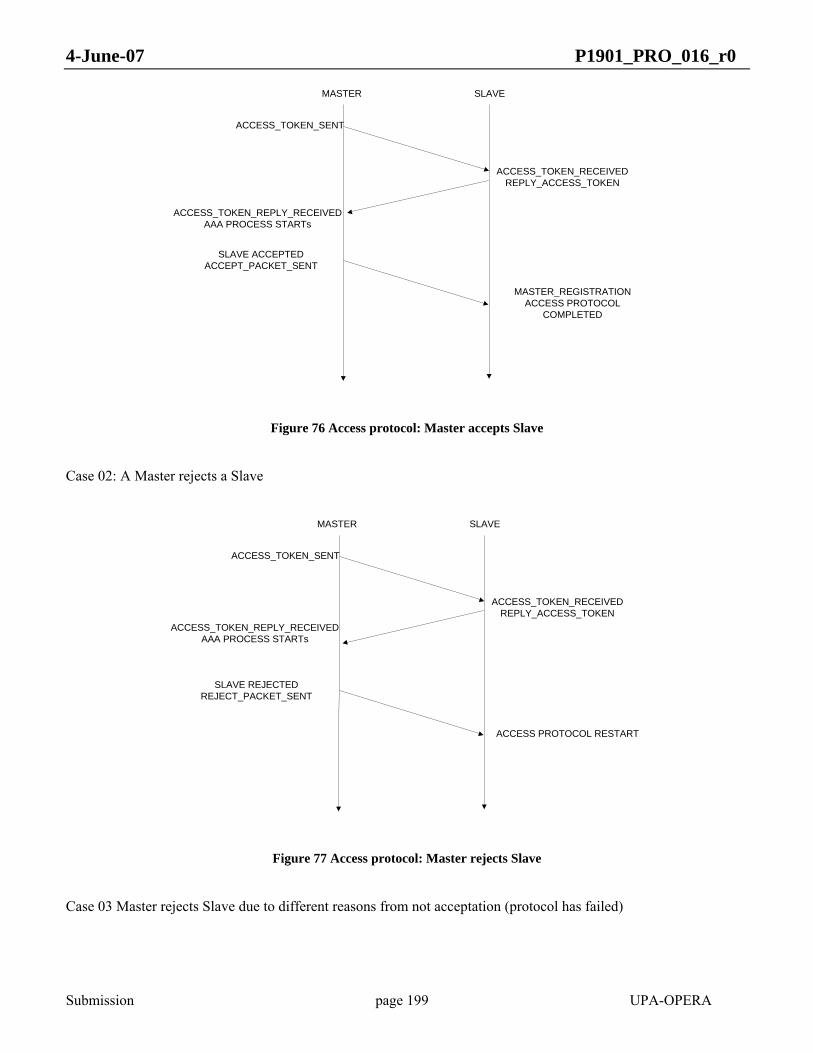
4-June-07 P1901_PRO_016_r0
Submission page 199 UPA-OPERA
ACCESS_TOKEN_SENT
ACCESS_TOKEN_RECEIVEDREPLY_ACCESS_TOKEN
MASTER SLAVE
ACCESS_TOKEN_REPLY_RECEIVEDAAA PROCESS STARTs
SLAVE ACCEPTEDACCEPT_PACKET_SENT
MASTER_REGISTRATIONACCESS PROTOCOL
COMPLETED
Figure 76 Access protocol: Master accepts Slave
Case 02: A Master rejects a Slave
ACCESS_TOKEN_SENT
ACCESS_TOKEN_RECEIVEDREPLY_ACCESS_TOKEN
MASTER SLAVE
SLAVE REJECTEDREJECT_PACKET_SENT
ACCESS PROTOCOL RESTART
ACCESS_TOKEN_REPLY_RECEIVEDAAA PROCESS STARTs
Figure 77 Access protocol: Master rejects Slave
Case 03 Master rejects Slave due to different reasons from not acceptation (protocol has failed)

4-June-07 P1901_PRO_016_r0
Submission page 200 UPA-OPERA
ACCESS_TOKEN_SENT
ACCESS_TOKEN_RECEIVEDREPLY_ACCESS_TOKEN
MASTER SLAVE
SLAVE REJECTEDFAILED_PACKET_SENT
ACCESS PROTOCOL RESTART
ACCESS_TOKEN_REPLY_RECEIVEDAAA PROCESS STARTs
Figure 78 Access protocol: registration failed
Case 04: Slave response is lost
ACCESS_TOKEN_SENT
ACCESS_TOKEN_RECEIVEDREPLY_ACCESS_TOKEN
MASTER SLAVE
MASTER_REGISTRATIONACCESS PROTOCOL
COMPLETED
ACCESS_TOKEN_SENT
ACCESS_TOKEN_RECEIVEDREPLY_ACCESS_TOKEN
SLAVE ACCEPTEDACCEPT_PACKET_SENT
Figure 79 Access protocol: Slave response is lost
Case 05: Master acceptation packet is lost. Protocol starts again after expiring timers waiting for master reply.
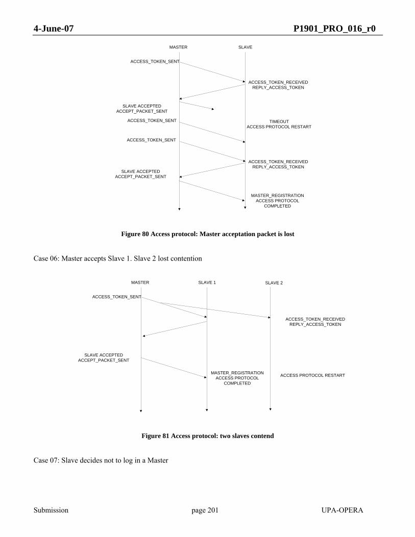
4-June-07 P1901_PRO_016_r0
Submission page 201 UPA-OPERA
ACCESS_TOKEN_SENT
ACCESS_TOKEN_RECEIVEDREPLY_ACCESS_TOKEN
MASTER SLAVE
MASTER_REGISTRATIONACCESS PROTOCOL
COMPLETED
ACCESS_TOKEN_RECEIVEDREPLY_ACCESS_TOKEN
SLAVE ACCEPTEDACCEPT_PACKET_SENT
ACCESS_TOKEN_SENT
TIMEOUTACCESS PROTOCOL RESTART
SLAVE ACCEPTEDACCEPT_PACKET_SENT
ACCESS_TOKEN_SENT
Figure 80 Access protocol: Master acceptation packet is lost
Case 06: Master accepts Slave 1. Slave 2 lost contention
ACCESS_TOKEN_SENT
MASTER SLAVE 1
SLAVE ACCEPTEDACCEPT_PACKET_SENT
SLAVE 2
ACCESS_TOKEN_RECEIVEDREPLY_ACCESS_TOKEN
ACCESS PROTOCOL RESTARTMASTER_REGISTRATIONACCESS PROTOCOL
COMPLETED
Figure 81 Access protocol: two slaves contend
Case 07: Slave decides not to log in a Master
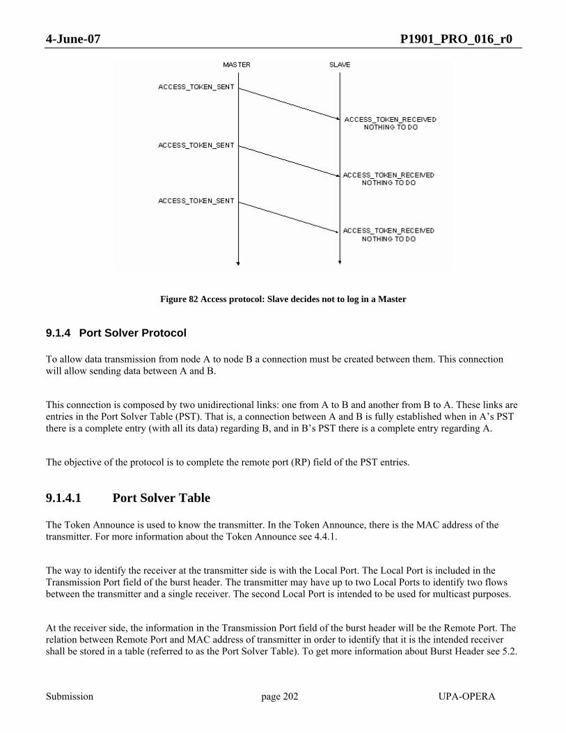
4-June-07 P1901_PRO_016_r0
Submission page 202 UPA-OPERA
Figure 82 Access protocol: Slave decides not to log in a Master
9.1.4 Port Solver Protocol
To allow data transmission from node A to node B a connection must be created between them. This connection will allow sending data between A and B.
This connection is composed by two unidirectional links: one from A to B and another from B to A. These links are entries in the Port Solver Table (PST). That is, a connection between A and B is fully established when in A’s PST there is a complete entry (with all its data) regarding B, and in B’s PST there is a complete entry regarding A.
The objective of the protocol is to complete the remote port (RP) field of the PST entries.
9.1.4.1 Port Solver Table
The Token Announce is used to know the transmitter. In the Token Announce, there is the MAC address of the transmitter. For more information about the Token Announce see 4.4.1.
The way to identify the receiver at the transmitter side is with the Local Port. The Local Port is included in the Transmission Port field of the burst header. The transmitter may have up to two Local Ports to identify two flows between the transmitter and a single receiver. The second Local Port is intended to be used for multicast purposes.
At the receiver side, the information in the Transmission Port field of the burst header will be the Remote Port. The relation between Remote Port and MAC address of transmitter in order to identify that it is the intended receiver shall be stored in a table (referred to as the Port Solver Table). To get more information about Burst Header see 5.2.
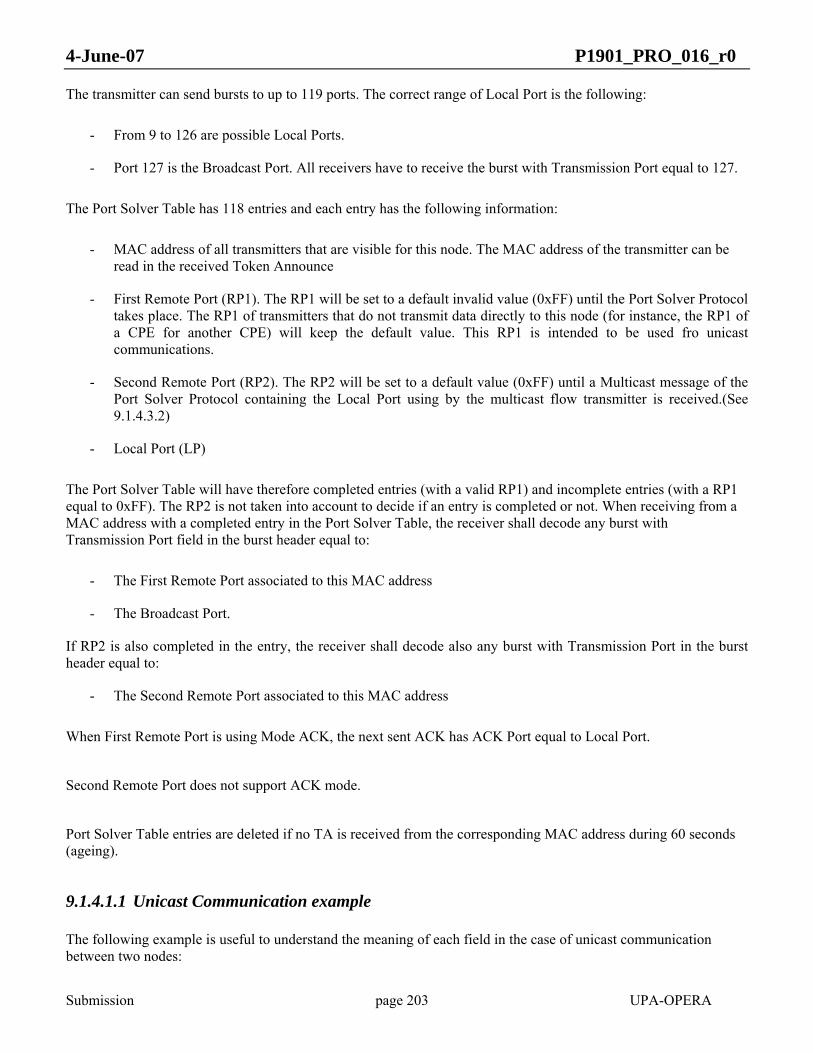
4-June-07 P1901_PRO_016_r0
Submission page 203 UPA-OPERA
The transmitter can send bursts to up to 119 ports. The correct range of Local Port is the following:
- From 9 to 126 are possible Local Ports.
- Port 127 is the Broadcast Port. All receivers have to receive the burst with Transmission Port equal to 127.
The Port Solver Table has 118 entries and each entry has the following information:
- MAC address of all transmitters that are visible for this node. The MAC address of the transmitter can be read in the received Token Announce
- First Remote Port (RP1). The RP1 will be set to a default invalid value (0xFF) until the Port Solver Protocol takes place. The RP1 of transmitters that do not transmit data directly to this node (for instance, the RP1 of a CPE for another CPE) will keep the default value. This RP1 is intended to be used fro unicast communications.
- Second Remote Port (RP2). The RP2 will be set to a default value (0xFF) until a Multicast message of the Port Solver Protocol containing the Local Port using by the multicast flow transmitter is received.(See 9.1.4.3.2)
- Local Port (LP)
The Port Solver Table will have therefore completed entries (with a valid RP1) and incomplete entries (with a RP1 equal to 0xFF). The RP2 is not taken into account to decide if an entry is completed or not. When receiving from a MAC address with a completed entry in the Port Solver Table, the receiver shall decode any burst with Transmission Port field in the burst header equal to:
- The First Remote Port associated to this MAC address
- The Broadcast Port.
If RP2 is also completed in the entry, the receiver shall decode also any burst with Transmission Port in the burst header equal to:
- The Second Remote Port associated to this MAC address
When First Remote Port is using Mode ACK, the next sent ACK has ACK Port equal to Local Port.
Second Remote Port does not support ACK mode.
Port Solver Table entries are deleted if no TA is received from the corresponding MAC address during 60 seconds (ageing).
9.1.4.1.1 Unicast Communication example
The following example is useful to understand the meaning of each field in the case of unicast communication between two nodes:

4-June-07 P1901_PRO_016_r0
Submission page 204 UPA-OPERA
Node A Node B
9
15
Figure 83 Ports example
To transmit a burst from A to B, the Transmission Port field is equal to 9.
To transmit a burst from B to A, the Transmission Port field is equal to 15.
In B the Port Solver Table has the following entry:
• MAC address equal to A MAC address • Local Port equal to 15. • First Remote Port equal to 9.
In A the Port Solver Table has the following entry:
• MAC address equal to B MAC address • Local Port equal to 9. • First Remote Port equal to 15.
The first remote port exchange process is described in section 9.1.4.2.
9.1.4.1.2 Multicast Communication example
The second remote port is intended to support native multicast using BPL by means of identify a physical unique link that will have its own tonemap and particular management, as described in section 9.1.2.1
In the following draw, node A has three links stablished. First one is a unicast link with node B, second another unicast link with node C and finally, a multicast link with nodes B and C. The local reference in node A for each of the links is its assigned Local Port, in this case 9, 10 and 12 respectively.
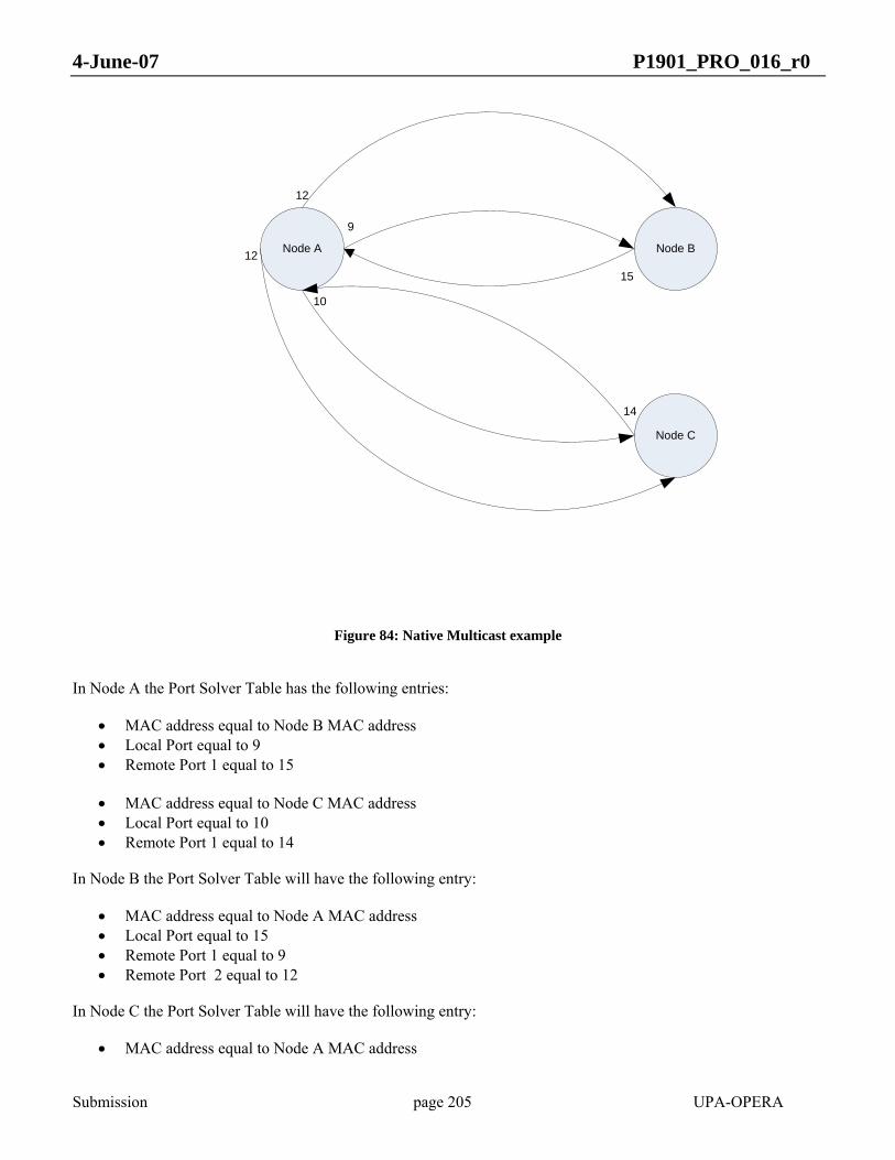
4-June-07 P1901_PRO_016_r0
Submission page 205 UPA-OPERA
Node A Node B
Node C
9
15
12
10
14
12
Figure 84: Native Multicast example
In Node A the Port Solver Table has the following entries:
• MAC address equal to Node B MAC address • Local Port equal to 9 • Remote Port 1 equal to 15 • MAC address equal to Node C MAC address • Local Port equal to 10 • Remote Port 1 equal to 14
In Node B the Port Solver Table will have the following entry:
• MAC address equal to Node A MAC address • Local Port equal to 15 • Remote Port 1 equal to 9 • Remote Port 2 equal to 12
In Node C the Port Solver Table will have the following entry:
• MAC address equal to Node A MAC address

4-June-07 P1901_PRO_016_r0
Submission page 206 UPA-OPERA
• Local Port equal to 14 • Remote Port 1 equal to 10 • Remote Port 2 equal to 12
When a burst with a Transmission Port field set to 12 is sent by Node A will be demodulated by Node B and Node C using the tonemap for the second port, which will be common for Node B and Node C in the reception. (See section 9.1.2) This way, the information will be sent only once.
9.1.4.2 First Port exchange process
The first port (RP1) exchange process is only executed between the master and the corresponding slaves. The protocol is always started by the master, after completion of the access protocol. The slave node cannot send the port solver message because it needs the token to transmit any packet, and to recognize that the token is addressed to it, it must know its RP1 with the master; that is, it has to complete the entry in its PST correspondent to the MAC address of its master.
To complete all the fields of an entry correspondent to a given MAC address, the first remote transmission port must be communicated by the node with that MAC address. A hand-shake protocol is used.
The node that wants to complete the entry sends a Port Solver Message (PSM) addressed to the MAC address of the PST entry. When a node receives a PSM, it answers with another PSM (Figure 85). The main contents of the PSM are the LP and the flag field. The flag field is set to zero by default. The flag field must be set to 1 when a PSM is received and the correspondent entry is already completed (Figure 87). A received PSM with this flag set to 1 will not require an answer.
PSM(LP 3, 0)
PSM(LP 5, 1)
Node A Node B
Node B entry addedEntry: (MAC B, LP 3, RP1 -)
Entry: (MAC A, LP 5, RP1 3)
Node A entry addedEntry: (MAC A, LP 5, RP1 -)
Entry: (MAC B, LP 3, RP1 5)
Figure 85 Port Solver Protocol Messages Exchange to complete First remote Port
If a response to PSM is not received, the entry will not be completed and a new PSM must be sent (Figure 86, Figure 87). There is a minimum time between PSM retransmissions. If the entry remains in the PST, the protocol must be followed until its success.

4-June-07 P1901_PRO_016_r0
Submission page 207 UPA-OPERA
Figure 86 Port Solver Protocol Messages Exchange to complete First remote Port

4-June-07 P1901_PRO_016_r0
Submission page 208 UPA-OPERA
PSM(LP 3, 0)
PSM(LP 5, 1)
Node A Node B
Node B entry addedEntry: (MAC B, LP 3, RP1 -)
Entry: (MAC A, LP 5, RP1 3)
Node A entry addedEntry: (MAC A, LP 5, RP1 -)
Entry: (MAC B, LP 3, RP1 5)
PSM(LP 3, 0)
PSM(LP 3, 0)
Entry: (MAC B, LP 3, RP1 -)
PSM(LP 3, 0)
Entry: (MAC A, LP 5, RP1 3)PSM(LP 5, 1)
Figure 87 Port Solver Protocol Messages Exchange to complete First remote Port
Every time a PSM is received, the correspondent entry in the PST must be updated because the first remote port can change.
Every time the LP is changed, the RP1 must be set to an invalid value and the protocol started.
9.1.4.3 Second Port exchange process
The second port (RP2) exchange process is only executed when the unicast link between origin and destination of multicast flow has been previously established. The protocol is always started by the origin of the multicast flow, that, through higher level exchange of packets, respond to the petition of inclusion or exclusion of certain node, identified by the Local Port assigned to the previously established unicast link, into a multicast flow, identified by a Local Port in the traffic origin.The response will be to trigger the Second Port (RP2) exchange process.
The origin of the multicast flow wil send a Posrt Solver Multicast Message (PSMM) addressed to the MAC address of the destination of the multicast flow. When a node receives a PSMM, it answers with a Port Solver Multicast ACK Message (PSMAM) to acknowledge the reception of the Local Port assigned in the transmission side to the

4-June-07 P1901_PRO_016_r0
Submission page 209 UPA-OPERA
multicast flow desired, and the RP2 (Second Remote Port) field of the entry indexed by the multicast origin MAC will be filled with this number.
Since this time, when receiving from a MAC address with a entry that contains RP1 and RP2 in the Port Solver Table, the receiver shall decode any burst with Transmission Port field in the burst header equal to RP1 and RP2.
The main contents of the PSMM are the LP assigned in the origin of the multicast flow and the flag field. The flag field is set to zero by default. A received PSMM with this flag set to 1 shall not require an answer.
PSMM(LP 12, 0)
PSMAM
Node A Node B
Node B wants to join multicast flow
With LP associated 12Entry: (MAC A, LP 5, RP1 3,
RP2 12)
Entry: (MAC A, LP 5, RP1 3, RP2 -)
Node B will receive data transmitted by port 3 and port
12 from Node A
Figure 88 Port Solver Protocol Messages Exchange to complete Second remote Port
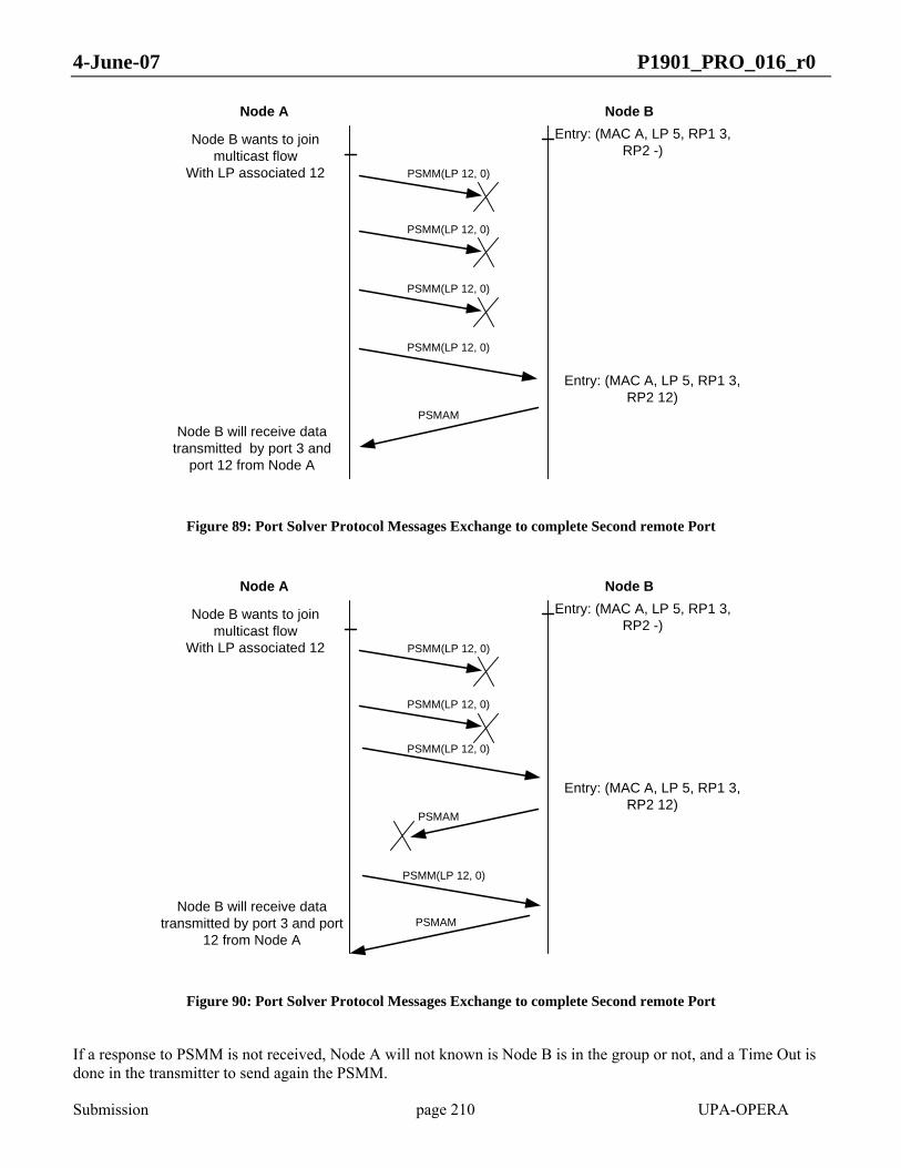
4-June-07 P1901_PRO_016_r0
Submission page 210 UPA-OPERA
PSMM(LP 12, 0)
PSMAM
Node A Node B
Node B wants to join multicast flow
With LP associated 12
Entry: (MAC A, LP 5, RP1 3, RP2 12)
Entry: (MAC A, LP 5, RP1 3, RP2 -)
Node B will receive data transmitted by port 3 and
port 12 from Node A
PSMM(LP 12, 0)
PSMM(LP 12, 0)
PSMM(LP 12, 0)
Figure 89: Port Solver Protocol Messages Exchange to complete Second remote Port
PSMM(LP 12, 0)
PSMAM
Node A Node B
Node B wants to join multicast flow
With LP associated 12
Entry: (MAC A, LP 5, RP1 3, RP2 12)
Entry: (MAC A, LP 5, RP1 3, RP2 -)
Node B will receive data transmitted by port 3 and port
12 from Node A
PSMM(LP 12, 0)
PSMM(LP 12, 0)
PSMM(LP 12, 0)
PSMAM
Figure 90: Port Solver Protocol Messages Exchange to complete Second remote Port
If a response to PSMM is not received, Node A will not known is Node B is in the group or not, and a Time Out is done in the transmitter to send again the PSMM.

4-June-07 P1901_PRO_016_r0
Submission page 211 UPA-OPERA
In the case of leaving a group, the protocol messages exchange will be the same, but replacing the LP associated by an invalid identifier (0xFF), as can be seen in the following figure:
PSMM(LP 0xFF, 0)
PSMAM
Node A Node B
Node B wants to leave multicast flow
With LP associated 12Entry: (MAC A, LP 5, RP1 3,
RP2 -)
Entry: (MAC A, LP 5, RP1 3, RP2 12)
Node B will receive data transmitted only by port 3
from Node A
Figure 91: Port Solver Protocol Exchange to delete Second Remote Port
PSMM(LP 0xFF, 0)
PSMAM
Node A Node B
Node B wants to leave multicast flow
With LP associated 12
Entry: (MAC A, LP 5, RP1 3, RP2 -)
Entry: (MAC A, LP 5, RP1 3, RP2 12)
Node B will receive data transmitted only by port 3
from Node A
PSMM(LP 0xFF, 0)
PSMM(LP 0xFF, 0)
PSMM(LP 0xFF, 0)
Figure 92 Port Solver Protocol Messages Exchange to delete Second Remote Port
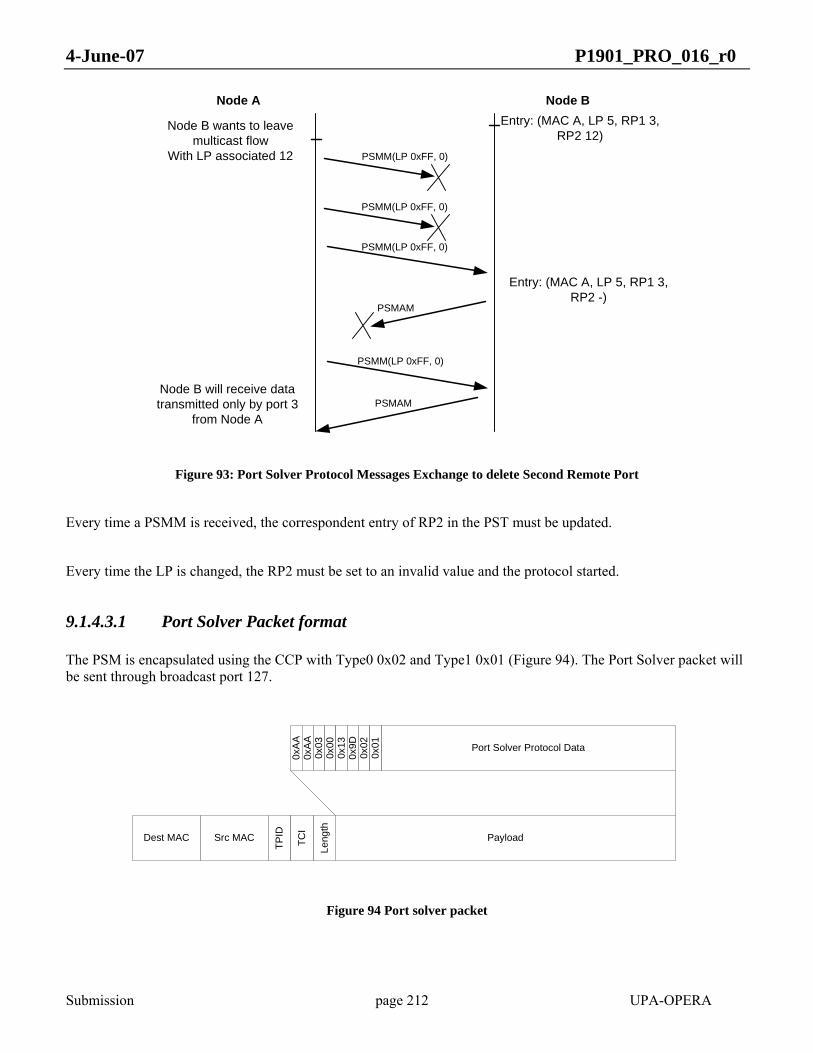
4-June-07 P1901_PRO_016_r0
Submission page 212 UPA-OPERA
PSMM(LP 0xFF, 0)
PSMAM
Node A Node B
Node B wants to leave multicast flow
With LP associated 12
Entry: (MAC A, LP 5, RP1 3, RP2 -)
Entry: (MAC A, LP 5, RP1 3, RP2 12)
Node B will receive data transmitted only by port 3
from Node A
PSMM(LP 0xFF, 0)
PSMM(LP 0xFF, 0)
PSMM(LP 0xFF, 0)
PSMAM
Figure 93: Port Solver Protocol Messages Exchange to delete Second Remote Port
Every time a PSMM is received, the correspondent entry of RP2 in the PST must be updated.
Every time the LP is changed, the RP2 must be set to an invalid value and the protocol started.
9.1.4.3.1 Port Solver Packet format
The PSM is encapsulated using the CCP with Type0 0x02 and Type1 0x01 (Figure 94). The Port Solver packet will be sent through broadcast port 127.
Dest MAC Src MAC Payload
0xA
A0x
AA
Port Solver Protocol Data
0x03
0x00
0x02
Leng
th
0x13
0x9D
0x01
TPID
TCI
Figure 94 Port solver packet

4-June-07 P1901_PRO_016_r0
Submission page 213 UPA-OPERA
Destination MAC must be the STP multicast address (0x0180C2000000) because PSMs are exchanged prior to the STP protocol. The packet shall be transmitted using the broadcast port (127). The PSM data fields are:
Bytes PSM data fields Length
0 – 5 Source MAC 6 bytes
6 – 11 Destination MAC 6 bytes
12 Assigned LP 1 byte
13 Info 1 byte
Table 24 Port solver packet fields
The format of the Info field is depicted in ¡Error! No se encuentra el origen de la referencia.:
Figure 95 Info field format
Bits number 1 to 4 are devoted to set the message type of the Capability Exchange Protocol (See section 0)
9.1.4.3.2 Port Solver Multicast Message (PSMM) format
The PSMM is encapsulated using the CCP with Type0 0x02 and Type1 0x03 (Figure 94). The Port Solver Multicast Message will be sent through broadcast port 127.
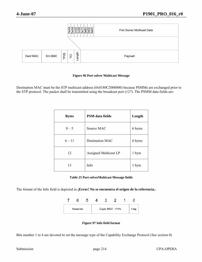
4-June-07 P1901_PRO_016_r0
Submission page 214 UPA-OPERA
Figure 96 Port solver Multicast Message
Destination MAC must be the STP multicast address (0x0180C2000000) because PSMMs are exchanged prior to the STP protocol. The packet shall be transmitted using the broadcast port (127). The PSMM data fields are:
Bytes PSM data fields Length
0 – 5 Source MAC 6 bytes
6 – 11 Destination MAC 6 bytes
12 Assigned Multicast LP 1 byte
13 Info 1 byte
Table 25 Port solverMulticast Message fields
The format of the Info field is depicted in ¡Error! No se encuentra el origen de la referencia.:
Figure 97 Info field format
Bits number 1 to 4 are devoted to set the message type of the Capability Exchange Protocol (See section 0)

4-June-07 P1901_PRO_016_r0
Submission page 215 UPA-OPERA
9.1.4.3.3 Port Solver Multicast Acknowledge Message (PSMAM) format
The PSMAM is encapsulated using the CCP with Type0 0x02 and Type1 0x04 (Figure 94). The Port Solver Multicast Message will be sent through broadcast port 127.
Figure 98 Port solver ACK Multicast Message
Destination MAC must be the STP multicast address (0x0180C2000000) because PSMAMs are exchanged prior to the STP protocol. The packet shall be transmitted using the broadcast port (127). The PSMAM data fields are:
Bytes PSM data fields Length
0 – 5 Source MAC 6 bytes
6 – 11 Destination MAC 6 bytes
12 Acknowledged Multicast LP
1 byte
13 Info 1 byte
Table 26 Port solverMulticast Message fields
The format of the Info field is depicted in ¡Error! No se encuentra el origen de la referencia.:
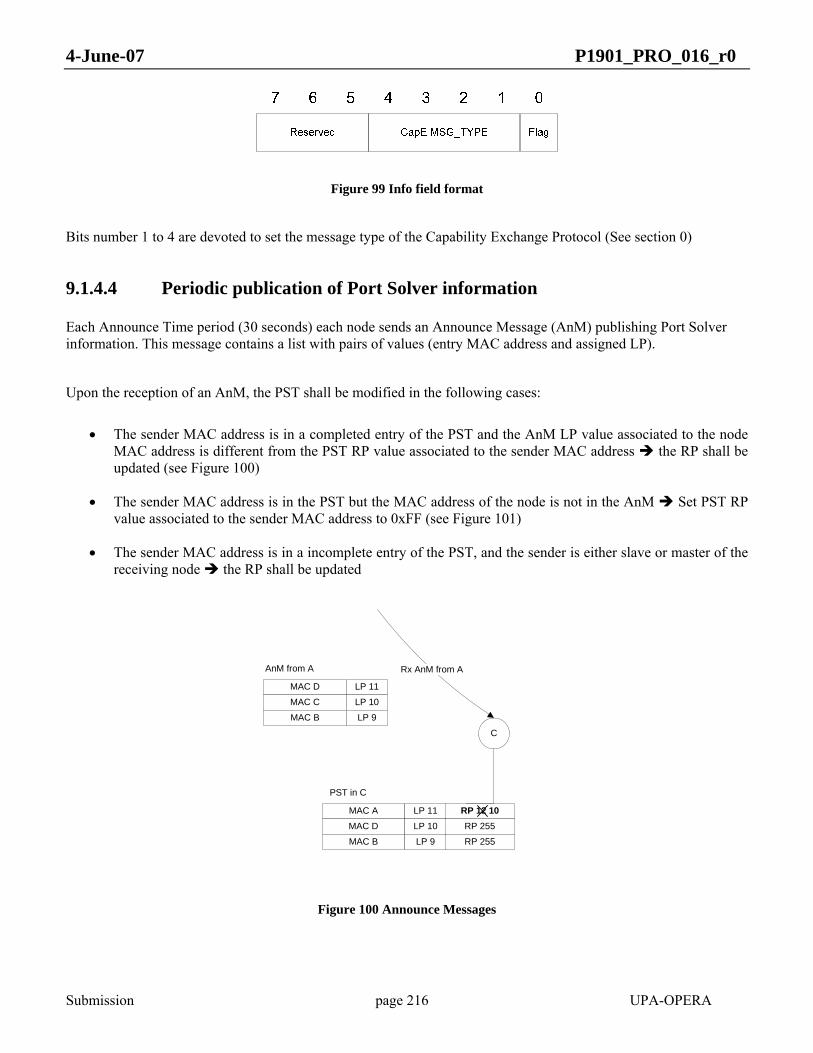
4-June-07 P1901_PRO_016_r0
Submission page 216 UPA-OPERA
Figure 99 Info field format
Bits number 1 to 4 are devoted to set the message type of the Capability Exchange Protocol (See section 0)
9.1.4.4 Periodic publication of Port Solver information
Each Announce Time period (30 seconds) each node sends an Announce Message (AnM) publishing Port Solver information. This message contains a list with pairs of values (entry MAC address and assigned LP).
Upon the reception of an AnM, the PST shall be modified in the following cases:
• The sender MAC address is in a completed entry of the PST and the AnM LP value associated to the node MAC address is different from the PST RP value associated to the sender MAC address the RP shall be updated (see Figure 100)
• The sender MAC address is in the PST but the MAC address of the node is not in the AnM Set PST RP value associated to the sender MAC address to 0xFF (see Figure 101)
• The sender MAC address is in a incomplete entry of the PST, and the sender is either slave or master of the receiving node the RP shall be updated
MAC D LP 11
MAC C LP 10
MAC B LP 9
AnM from A
MAC A LP 11
MAC D LP 10
MAC B LP 9
PST in C
RP 12 10RP 255
RP 255
C
Rx AnM from A
Figure 100 Announce Messages
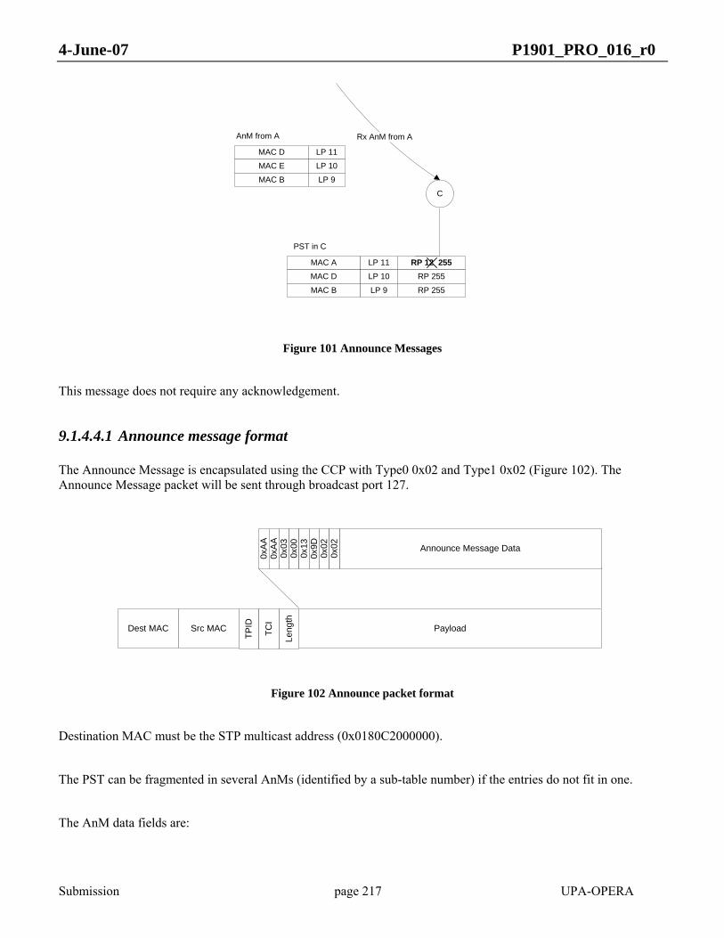
4-June-07 P1901_PRO_016_r0
Submission page 217 UPA-OPERA
MAC D LP 11
MAC E LP 10
MAC B LP 9
AnM from A
MAC A LP 11
MAC D LP 10
MAC B LP 9
PST in C
RP 12 255RP 255
RP 255
C
Rx AnM from A
Figure 101 Announce Messages
This message does not require any acknowledgement.
9.1.4.4.1 Announce message format
The Announce Message is encapsulated using the CCP with Type0 0x02 and Type1 0x02 (Figure 102). The Announce Message packet will be sent through broadcast port 127.
Dest MAC Src MAC Payload
0xA
A0x
AA
Announce Message Data
0x03
0x00
0x02
Leng
th
0x13
0x9D
0x02
TPID
TCI
Figure 102 Announce packet format
Destination MAC must be the STP multicast address (0x0180C2000000).
The PST can be fragmented in several AnMs (identified by a sub-table number) if the entries do not fit in one.
The AnM data fields are:
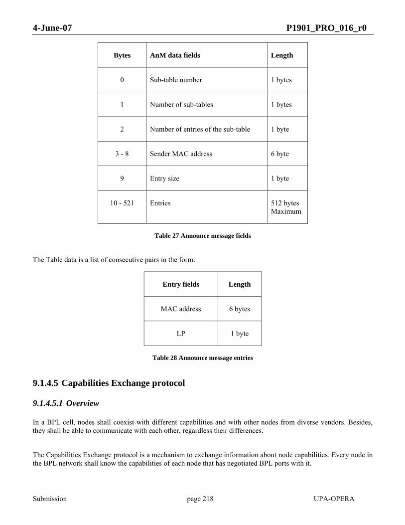
4-June-07 P1901_PRO_016_r0
Submission page 218 UPA-OPERA
Bytes AnM data fields Length
0 Sub-table number 1 bytes
1 Number of sub-tables 1 bytes
2 Number of entries of the sub-table 1 byte
3 - 8 Sender MAC address 6 byte
9 Entry size 1 byte
10 - 521 Entries 512 bytes Maximum
Table 27 Announce message fields
The Table data is a list of consecutive pairs in the form:
Entry fields Length
MAC address 6 bytes
LP 1 byte
Table 28 Announce message entries
9.1.4.5 Capabilities Exchange protocol
9.1.4.5.1 Overview
In a BPL cell, nodes shall coexist with different capabilities and with other nodes from diverse vendors. Besides, they shall be able to communicate with each other, regardless their differences.
The Capabilities Exchange protocol is a mechanism to exchange information about node capabilities. Every node in the BPL network shall know the capabilities of each node that has negotiated BPL ports with it.
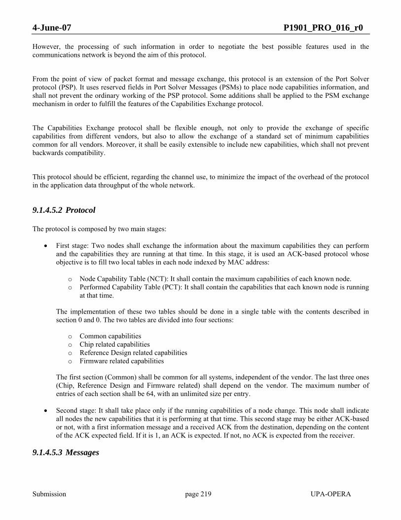
4-June-07 P1901_PRO_016_r0
Submission page 219 UPA-OPERA
However, the processing of such information in order to negotiate the best possible features used in the communications network is beyond the aim of this protocol.
From the point of view of packet format and message exchange, this protocol is an extension of the Port Solver protocol (PSP). It uses reserved fields in Port Solver Messages (PSMs) to place node capabilities information, and shall not prevent the ordinary working of the PSP protocol. Some additions shall be applied to the PSM exchange mechanism in order to fulfill the features of the Capabilities Exchange protocol.
The Capabilities Exchange protocol shall be flexible enough, not only to provide the exchange of specific capabilities from different vendors, but also to allow the exchange of a standard set of minimum capabilities common for all vendors. Moreover, it shall be easily extensible to include new capabilities, which shall not prevent backwards compatibility.
This protocol should be efficient, regarding the channel use, to minimize the impact of the overhead of the protocol in the application data throughput of the whole network.
9.1.4.5.2 Protocol
The protocol is composed by two main stages:
• First stage: Two nodes shall exchange the information about the maximum capabilities they can perform and the capabilities they are running at that time. In this stage, it is used an ACK-based protocol whose objective is to fill two local tables in each node indexed by MAC address:
o Node Capability Table (NCT): It shall contain the maximum capabilities of each known node. o Performed Capability Table (PCT): It shall contain the capabilities that each known node is running
at that time.
The implementation of these two tables should be done in a single table with the contents described in section 0 and 0. The two tables are divided into four sections:
o Common capabilities o Chip related capabilities o Reference Design related capabilities o Firmware related capabilities
The first section (Common) shall be common for all systems, independent of the vendor. The last three ones (Chip, Reference Design and Firmware related) shall depend on the vendor. The maximum number of entries of each section shall be 64, with an unlimited size per entry.
• Second stage: It shall take place only if the running capabilities of a node change. This node shall indicate all nodes the new capabilities that it is performing at that time. This second stage may be either ACK-based or not, with a first information message and a received ACK from the destination, depending on the content of the ACK expected field. If it is 1, an ACK is expected. If not, no ACK is expected from the receiver.
9.1.4.5.3 Messages
4-June-07 P1901_PRO_016_r0
Submission page 220 UPA-OPERA
One of the two possible schemes explained below can be used to send the vendor dependent information within the maximum capabilities messages (MAX_CAP_MSG(xxx)):
• Indexed scheme: Only the vendor related information shall be sent, and the maximum capabilities shall be inferred by the receiver. As a result, less data shall be transferred by the Capabilities Exchange protocol, minimizing the overhead.
• Enumerated scheme: Node vendor and capabilities shall be sent as an enumeration.
In case a node does not understand the indexed scheme, it shall send a NACK to the sender in response. In any case, the common capabilities section is always sent in the message using an enumerated scheme.
The information within the running capabilities messages (RUN_CAP_MSG) shall be sent in a different way. First, a field containing the default mode shall be sent. This field shall indicate what shall be the value for a running capability that is not sent in the message. The possible values can be two:
• Maximum capability. • Minimum capability.
Once the default field content is clear, the running capabilities that do not match with this default value shall be sent using a group of two fields. The first one shall indicate the position of the capability in the NCT, and the second one, its value. In addition to the information itself, a message mode shall be filled, indicating whether the node has changed its running capabilities, or it is a simply information message to the others nodes.
9.1.4.5.3.1 Capability Element (CapE)
A capability element is a structure composed by several and variable number of fields. All protocol messages are built using this structure. Four can be the protocol messages to be composed:
• MAX_CAP_MSG(xxx): This message shall contain the maximum capabilities that a node can perform. It shall be divided into two main sections. The first one is the common capabilities section, which includes all these capabilities that are vendor independent, and have been previously approved by all vendors as a standard. The second one is the vendor capabilities section that shall be divided into three subsections. Either these subsections can be transmitted entirely (enumerated scheme) or sent using only an index (indexed scheme), enough for the receiver to understand all the capabilities related to each subsection. In this case, the indication (xxx) shall be substituted by a 1 in the position relative to each of the subsections. That is, if only the Chip related capabilities are sent using the index, the indication becomes (100). The subsections are the following:
o Chip related capabilities: All the capabilities that depend directly on the chip. If sent by index, it shall be indicated with a 1 in the first position of the index indicator. A list of Chip related capabilities is presented in section 0.
o Firmware related capabilities: All the capabilities that depend on the Firmware version. If sent by index, it shall be indicated with a 1 in the second position of the index indicator. A list of Firmware related capabilities is presented in section 0.
o Reference Design related capabilities: All the capabilities that depend on the Reference Design. If sent by index, it shall be indicated with a 1 in the third position of the index indicator. A list of Reference Design related capabilities is presented in section 0.
• RUN_CAP_MSG: In this message, the running but not the maximum capabilities of the node shall be sent.
Its objective is to fill the PCT. The first field shall notate the transmission mode, where the nature of the message, if it is a simply informational message or includes a notification of change in the running
4-June-07 P1901_PRO_016_r0
Submission page 221 UPA-OPERA
capabilities, is transmitted. A second field telling the default value for the running capabilities that are not explicitly indicated in the message shall be sent. This default value can be the highest possible capability of the node or the lowest possible one. Then, the position of the capability in the NCT using a section indicator (Common, Chip, Firmware or Reference Design subsection) followed by the position of the capability in the section of the NCT shall be sent, associated with a value for this capability, that shall be wrote in the PCT.
• ACK_CAP_ANN: Acknowledge of all sections of a MAX_CAP_MSG (xxx) message and also a previous RUN_CAP_MSG if they were sent with the ACK expected field set to 1. A sender cannot send two messages that expect two different ACKs. If a composed message with a MAX_CAP_MSG(xxx) and a RUN_CAP_MSG is sent, only an ACK_CAP_ANN shall be expected. If the sender decides to send both messages separately, first it shall expect the ACK_CAP_ANN for the MAX_CAP_MSG(xxx); and then, it shall transmit the RUN_CAP_MSG and expect another ACK_CAP_ANN for it. If some section of the MAX_CAP_MSG has not been correctly decoded, i.e. the index is not recognized by the destination node, (and cannot fill the NCT using only this data) then the message sent in response shall be a NACK_CAP_ANN (xxx) instead, with a 1 in the non-correctly decoded section.
• NACK_CAP_ANN(xxx): One or more sections of the MAX_CAP_MSG(xxx) section sent by index have not been recognized by the receptor, because no index found, or table structure not known.
Each type of Capabilities Exchange protocol message shall be identified by a field called MSG_TYPE. Please refer to section 0 for further details on this issue.
Those messages can be composed encapsulating several of them into one Port Solver Message (PSM); therefore it is saved some overhead due to protocol encapsulation.
Each one of the messages and how to compose them is discussed in the following subsections.
9.1.4.5.3.2 MAX_CAP_MSG message
This message shall begin with one field devoted to indicate the number of sets of maximum capabilities that are sent in the message.
Depending on the decision performed in the node, it shall transmit the MAX_CAP_MSG message with either its maximum capabilities only (Single Node Publication) or the maximum capabilities of all the nodes it knows (All Known Nodes Publication). Although only the Single Node Publication method should be used, it is also possible to use the All Known Nodes Publication method.
In the first case (Single Node Publication), this field shall be set to 1, and in the second case (All Known Nodes Publication), it shall be set to the number of known nodes with a complete filled NCT plus one.

4-June-07 P1901_PRO_016_r0
Submission page 222 UPA-OPERA
The second section shall include the data themselves and can contain the maximum capabilities of either one or several nodes.
Each set of maximum capabilities shall be preceded by the MAC address of the node that can perform this set of capabilities.
The different maximum capabilities that can be present in a BPL cell shall be divided into two different groups:
• Common capabilities (vendor independent capabilities) • Vendor dependent capabilities
Common capabilities shall be always sent in the messages. They are sent by means of a variable-length set of fields, whose contents and meaning will be determined by the protocol.
The vendor dependent capabilities shall be divided themselves in capabilities associated with:
• Chip version. • Reference design. • Firmware.
Common capabilities shall not require a division among chip, firmware or reference design related capabilities, because these capabilities shall be the same for all types of nodes and vendors.
On the other hand, vendor dependent capabilities shall be divided into the three described sections, because a solution may present different vendors for each part of the system; one vendor for the chip, other for the firmware and a third one for the reference design, and each vendor may sent its own information inside the vendor dependent section.
The Maximum Capabilities section of the MAX_CAP_MSG message shall follow this division also, with two main sections, where the first one shall be the common capabilities section and the second one the vendor dependent section.
The common capabilities section shall be simply composed by a first field of length in bytes, and a second variable-length field that shall include the fields that will be determined by the protocol. There are up to 64 entries in the NCT and PCT for common capabilities.
The vendor dependent capabilities section shall be subdivided into three main subsections: Chip, Reference Design and Firmware. For each subsection, two possible schemes of sending capabilities shall be allowed: Indexed and Enumerated.
When using the Indexed scheme, it is only required to send a part of sender’s NCT to fill the entire NCT in the receiver.
The second one shall be simply an enumeration of each of the capabilities that a node has.

4-June-07 P1901_PRO_016_r0
Submission page 223 UPA-OPERA
An indexed section shall be simply an enumeration covering only the minimum possible set of capabilities. This minimum set shall depend on the vendor. The proposed set is the following:
Section Set of capabilities to be an index
Chip Chip Vendor
Chip Version
Reference Design RD Vendor
RD Family
RD Version
Firmware FW Vendor
FW Family
FW Version
Table 29 Proposed vendor dependent capabilities indexes
As the vendor may be different for each section, it shall be indicated in each of the sections.
The number of enumerated capabilities may change from node to node depending on the version of each one, but the capabilities order shall remain the same.
The following figure presents an example of Maximum Capabilities section, where N sets of capabilities are sent. Inside each set, the three sections described below can be found, and, in this example, the enumerated mode is used, containing all the proposed fields. The common section is empty, because the contents and meaning of its fields are not determined yet. As a result, the length_of the common field is set to 0:
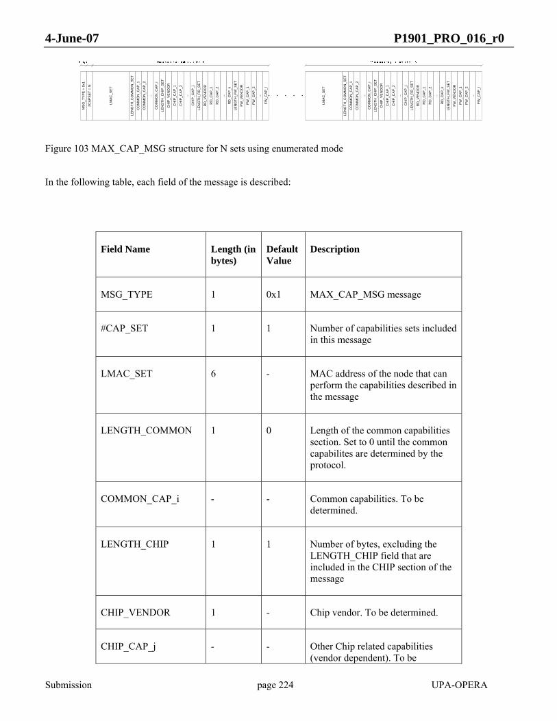
4-June-07 P1901_PRO_016_r0
Submission page 224 UPA-OPERA
MS
G_T
YP
E =
0x1
#CA
PS
ET
= N
LEN
GTH
_CO
MM
ON
_SE
T
CO
MM
ON
_CA
P_1
CO
MM
ON
_CA
P_2
…
CO
MM
ON
_CA
P_i
LEN
GTH
_CH
IP_S
ET
CH
IP_V
EN
DO
R
CH
IP_C
AP_
1
CH
IP_C
AP_
2
…
CH
IP_C
AP
_j
LEN
GTH
_RD
_SE
T
LMA
C_S
ET
RD
_VE
ND
OR
RD
_CA
P_1
RD
_CA
P_2
…
RD
_CA
P_k
LEN
GTH
_FW
_SE
T
FW_V
EN
DO
R
FW_C
AP_1
FW_C
AP_2
…
FW_C
AP
_l
LEN
GTH
_CO
MM
ON
_SE
T
CO
MM
ON
_CA
P_1
CO
MM
ON
_CA
P_2
…
CO
MM
ON
_CA
P_i
LEN
GTH
_CH
IP_S
ET
CH
IP_V
EN
DO
R
CH
IP_C
AP_
1
CH
IP_C
AP_
2
…
CH
IP_C
AP
_j
LEN
GTH
_RD
_SE
T
LMA
C_S
ET
RD
_VE
ND
OR
RD
_CA
P_1
RD
_CA
P_2
…
RD
_CA
P_k
LEN
GTH
_FW
_SE
T
FW_V
EN
DO
R
FW_C
AP_1
FW_C
AP_2
…
FW_C
AP
_l
Figure 103 MAX_CAP_MSG structure for N sets using enumerated mode
In the following table, each field of the message is described:
Field Name Length (in bytes)
Default Value
Description
MSG_TYPE 1 0x1 MAX_CAP_MSG message
#CAP_SET 1 1 Number of capabilities sets included in this message
LMAC_SET 6 - MAC address of the node that can perform the capabilities described in the message
LENGTH_COMMON 1 0 Length of the common capabilities section. Set to 0 until the common capabilites are determined by the protocol.
COMMON_CAP_i - - Common capabilities. To be determined.
LENGTH_CHIP 1 1 Number of bytes, excluding the LENGTH_CHIP field that are included in the CHIP section of the message
CHIP_VENDOR 1 - Chip vendor. To be determined.
CHIP_CAP_j - - Other Chip related capabilities (vendor dependent). To be
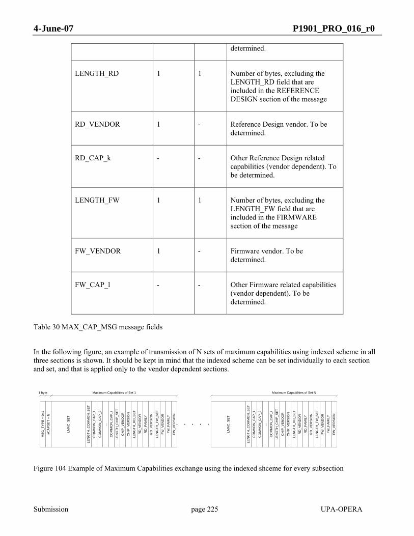
4-June-07 P1901_PRO_016_r0
Submission page 225 UPA-OPERA
determined.
LENGTH_RD 1 1 Number of bytes, excluding the LENGTH_RD field that are included in the REFERENCE DESIGN section of the message
RD_VENDOR 1 - Reference Design vendor. To be determined.
RD_CAP_k - - Other Reference Design related capabilities (vendor dependent). To be determined.
LENGTH_FW 1 1 Number of bytes, excluding the LENGTH_FW field that are included in the FIRMWARE section of the message
FW_VENDOR 1 - Firmware vendor. To be determined.
FW_CAP_l - - Other Firmware related capabilities (vendor dependent). To be determined.
Table 30 MAX_CAP_MSG message fields
In the following figure, an example of transmission of N sets of maximum capabilities using indexed scheme in all three sections is shown. It should be kept in mind that the indexed scheme can be set individually to each section and set, and that is applied only to the vendor dependent sections.
1 byte
MSG
_TY
PE
= 0x
1
#CA
PS
ET
= N
LEN
GTH
_CO
MM
ON
_SE
T
CO
MM
ON
_CA
P_1
CO
MM
ON
_CA
P_2
…
CO
MM
ON
_CAP
_i
LEN
GTH
_CH
IP_S
ET
CH
IP_V
EN
DO
R
CH
IP_V
ER
SIO
N
LEN
GTH
_RD
_SE
T
LMA
C_S
ET
RD
_VE
ND
OR
RD
_FA
MIL
Y
RD
_VE
RSI
ON
Maximum Capabilities of Set 1 Maximum Capabilities of Set N
LEN
GTH
_FW
_SE
T
FW_V
END
OR
FW_F
AMIL
Y
FW_V
ER
SIO
N
LEN
GTH
_CO
MM
ON
_SE
T
CO
MM
ON
_CA
P_1
CO
MM
ON
_CA
P_2
…
CO
MM
ON
_CAP
_i
LEN
GTH
_CH
IP_S
ET
CH
IP_V
EN
DO
R
CH
IP_V
ER
SIO
N
LEN
GTH
_RD
_SE
T
LMA
C_S
ET
RD
_VE
ND
OR
RD
_FA
MIL
Y
RD
_VE
RSI
ON
LEN
GTH
_FW
_SE
T
FW_V
END
OR
FW_F
AMIL
Y
FW_V
ER
SIO
N
Figure 104 Example of Maximum Capabilities exchange using the indexed shceme for every subsection
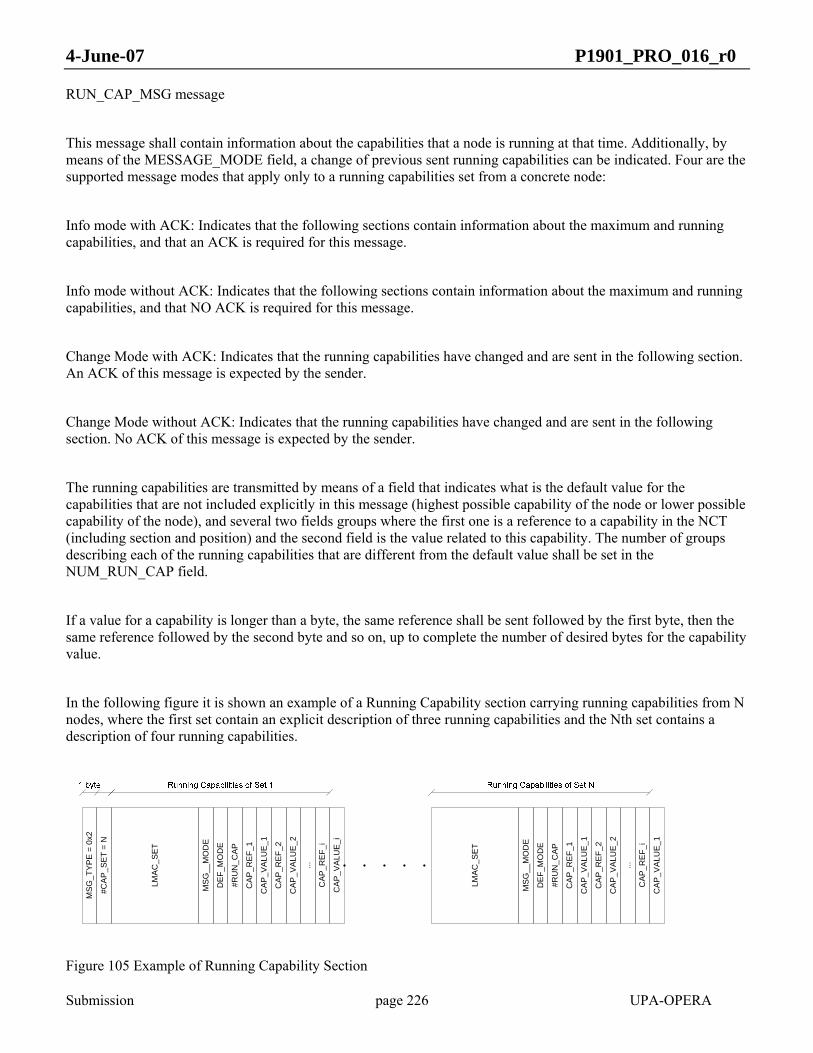
4-June-07 P1901_PRO_016_r0
Submission page 226 UPA-OPERA
RUN_CAP_MSG message
This message shall contain information about the capabilities that a node is running at that time. Additionally, by means of the MESSAGE_MODE field, a change of previous sent running capabilities can be indicated. Four are the supported message modes that apply only to a running capabilities set from a concrete node:
Info mode with ACK: Indicates that the following sections contain information about the maximum and running capabilities, and that an ACK is required for this message.
Info mode without ACK: Indicates that the following sections contain information about the maximum and running capabilities, and that NO ACK is required for this message.
Change Mode with ACK: Indicates that the running capabilities have changed and are sent in the following section. An ACK of this message is expected by the sender.
Change Mode without ACK: Indicates that the running capabilities have changed and are sent in the following section. No ACK of this message is expected by the sender.
The running capabilities are transmitted by means of a field that indicates what is the default value for the capabilities that are not included explicitly in this message (highest possible capability of the node or lower possible capability of the node), and several two fields groups where the first one is a reference to a capability in the NCT (including section and position) and the second field is the value related to this capability. The number of groups describing each of the running capabilities that are different from the default value shall be set in the NUM_RUN_CAP field.
If a value for a capability is longer than a byte, the same reference shall be sent followed by the first byte, then the same reference followed by the second byte and so on, up to complete the number of desired bytes for the capability value.
In the following figure it is shown an example of a Running Capability section carrying running capabilities from N nodes, where the first set contain an explicit description of three running capabilities and the Nth set contains a description of four running capabilities.
MSG
_TY
PE
= 0x
2
#CA
P_S
ET
= N
MSG
__M
OD
E
DE
F_M
OD
E
#RU
N_C
AP
CA
P_R
EF_
1
CAP
_VAL
UE_
1
CA
P_R
EF_
2
CAP
_VAL
UE_
2
CAP
_RE
F_i
CAP
_VA
LUE
_i
LMA
C_S
ET
MSG
__M
OD
E
DE
F_M
OD
E
#RU
N_C
AP
CA
P_R
EF_
1
CAP
_VAL
UE_
1
CA
P_R
EF_
2
CAP
_VAL
UE_
2
CAP
_RE
F_i
CAP
_VAL
UE_
1
LMA
C_S
ET
......
Figure 105 Example of Running Capability Section

4-June-07 P1901_PRO_016_r0
Submission page 227 UPA-OPERA
Field Name Length (in bytes)
Default Value
Description
MSG_TYPE 1 0x2 RUN_CAP_MSG message
#CAP_SET 1 1 Number of Running Capabilities individually described
LMAC_SET 6 - MAC address of the node that is performing the capabilities described in the message
MSG_MODE 1 0 0 – INFO message with ACK
1 – INFO message without ACK
2 – Change notification message with ACK
3 – Change notification message without ACK
DEF_MODE 1 0 0 – Highest Possible
1 – Lower Possible
#RUN_CAP 1 1 Number of running capabilities that will be described in this message
CAP_REF_i 1 0 Bits 1 to 0:
00 – Common Section
01 – Chip Section
10 – Reference Design Section

4-June-07 P1901_PRO_016_r0
Submission page 228 UPA-OPERA
11 – Firmware Section
Bits 7 to 2: Position of the capability in the section of the NCT
CAP_VALUE_i 1 - Value of the referenced capability
Table 31 RUN_CAP_MSG message fields
ACK_CAP_ANN message
MS
G_T
YP
E =
0x4
#CAP
_AC
K =
N
LMA
C_A
CK
_1
LMA
C_A
CK
_2
LMA
C_A
CK
_N
Figure 106 ACK_CAP_ANN message structure
The structure of the ACK_CAP_ANN message is very simple. It shall be composed by a first field, 1 byte wide, with the number of ACKs that composes the message, followed by the MAC addresses of the nodes whose capabilities have been received correctly.
Field Name Length (in bytes)
Default Value
Description
MSG_TYPE 1 0x4 ACK_CAP_ANN message
#CAP_ACK 1 1 Number of ACKs contained in the message
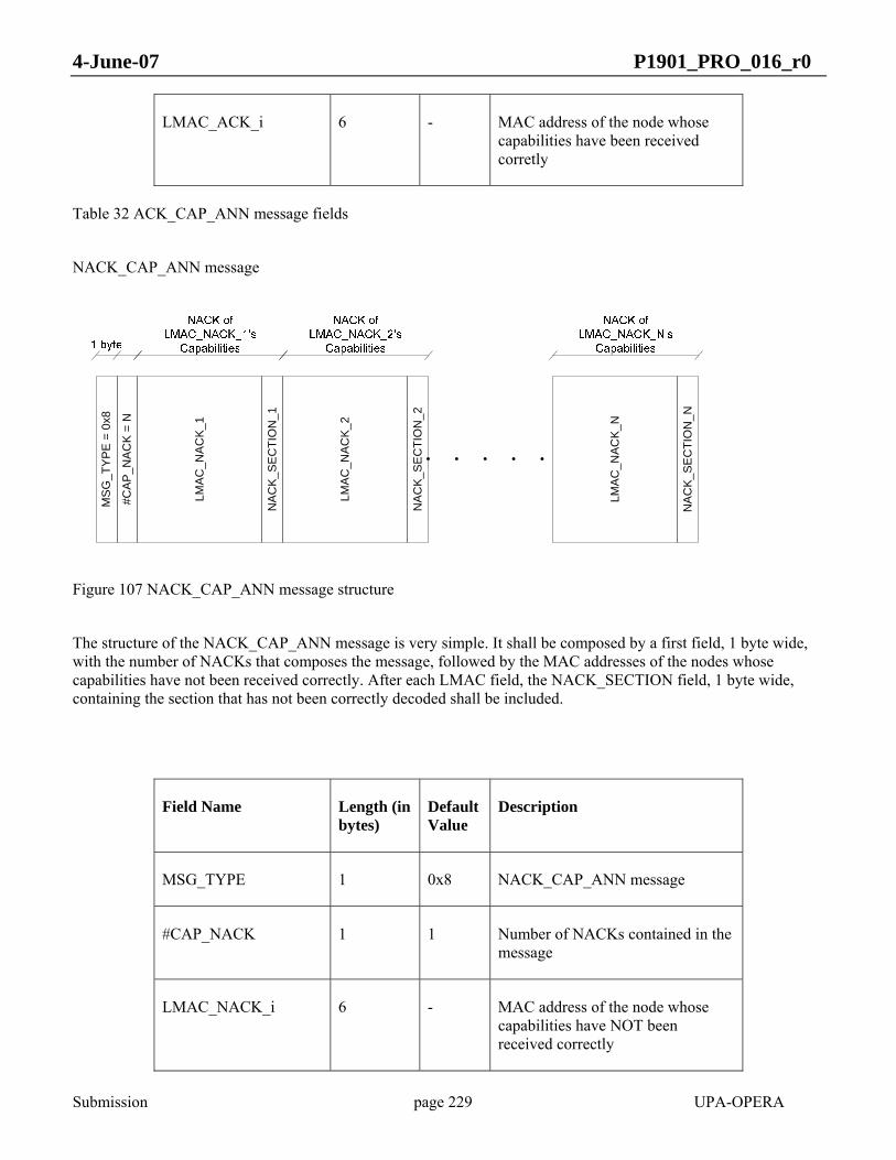
4-June-07 P1901_PRO_016_r0
Submission page 229 UPA-OPERA
LMAC_ACK_i 6 - MAC address of the node whose capabilities have been received corretly
Table 32 ACK_CAP_ANN message fields
NACK_CAP_ANN message
MS
G_T
YP
E =
0x8
#CA
P_N
AC
K =
N
LMA
C_N
AC
K_1
LMA
C_N
AC
K_2
LMA
C_N
ACK
_N
NA
CK
_SE
CTI
ON
_1
NA
CK
_SE
CTI
ON
_2
NA
CK
_SE
CTI
ON
_N
Figure 107 NACK_CAP_ANN message structure
The structure of the NACK_CAP_ANN message is very simple. It shall be composed by a first field, 1 byte wide, with the number of NACKs that composes the message, followed by the MAC addresses of the nodes whose capabilities have not been received correctly. After each LMAC field, the NACK_SECTION field, 1 byte wide, containing the section that has not been correctly decoded shall be included.
Field Name Length (in bytes)
Default Value
Description
MSG_TYPE 1 0x8 NACK_CAP_ANN message
#CAP_NACK 1 1 Number of NACKs contained in the message
LMAC_NACK_i 6 - MAC address of the node whose capabilities have NOT been received correctly

4-June-07 P1901_PRO_016_r0
Submission page 230 UPA-OPERA
NACK_SECTION_i 1 - Bit 0: if set to 1 means that CHIP section not correctly decoded.
Bit 1: if set to 1 means that REFERENCE DESIGN section not correctly decoded.
Bit 2: if set to 1 means that FIRMWARE section not correctly decoded.
Table 33 NACK_CAP_ANN message fields
Aggregated messages
In order to make the protocol more efficient, a message aggregation can be performed. It shall consist on changing the MSG_TYPE field code by the aggregation of up to three different messages types, as shown in Table 38. The order of the submessages in the final structure shall follow the scheme presented in the following figure, where some examples are proposed:
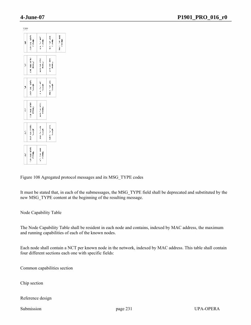
4-June-07 P1901_PRO_016_r0
Submission page 231 UPA-OPERA
1 byte
Figure 108 Agregated protocol messages and its MSG_TYPE codes
It must be stated that, in each of the submessages, the MSG_TYPE field shall be deprecated and substituted by the new MSG_TYPE content at the beginning of the resulting message.
Node Capability Table
The Node Capability Table shall be resident in each node and contains, indexed by MAC address, the maximum and running capabilities of each of the known nodes.
Each node shall contain a NCT per known node in the network, indexed by MAC address. This table shall contain four different sections each one with specific fields:
Common capabilities section
Chip section
Reference design

4-June-07 P1901_PRO_016_r0
Submission page 232 UPA-OPERA
Firmware
In each section, for each of the possible capabilities, two fields have to be filled. The first one shall be the maximum capability the node can perform. The second one shall be the real level of such capability that is performing at that time.
Common capabilities section
For the moment, this part of the table is empty, until the common capabilites are determined by the standard. The index shall be used to make a reference to a capability when transmitting the running capabilities as described in section 0.
Chip related fields
In the following table, the fields index, field name, length, default value and description, are presented. The index shall be used to make a reference to a capability when transmitting the running capabilities as described in section 0.
Index Field Name Length (in bits)
Default Value
Description
1 Chip Vendor 8 - Chip vendor. To be determined.
2 Chip Capability j - - Other Chip related capabilities (vendor dependent). To be determined.
…
Table 34 Chip related fields
Reference Design related fields
In the following table, the fields index, field name, length, default value and description, are presented. The index shall be used to make a reference to a capability when transmitting the running capabilities as described in section 0.

4-June-07 P1901_PRO_016_r0
Submission page 233 UPA-OPERA
Index Field Name Length (in bits)
Default Value
Description
1 RD Vendor 8 - Reference Design vendor. To be determined.
2 RD Capability k - - Other Reference Design related capabilities (vendor dependent). To be determined.
…
Table 35 Reference Design related fields
Firmware related fields
In the following table, the fields index, field name, length, default value and description, are presented. The index shall be used to make a reference to a capability when transmitting the running capabilities as described in section 0.
Index Field Name Length (in bits)
Default Value
Description
1 FW Vendor 8 - Firmware vendor. To be determined.
2 FW Capability l - - Other Firmware related capabilities (vendor dependent). To be determined.
…
Table 36 Firmware related fields
Performed Capability Table

4-June-07 P1901_PRO_016_r0
Submission page 234 UPA-OPERA
The PCT shall contain, for each possible capability, a value that indicates if the capability is performed or not, and the grade of functionality that is running at the time.
The PCT shall also be divided into four sections corresponding to the above mentioned groups of capabilities: Common, Chip, Reference Design and Firmware related.
The common capabilities section is empty until a decision on which capabilities must be considered common for all vendors is reached. The table is structured as follows:
Capability Section Index Value Default High Value
Default Low Value
Chip Vendor 1 - - -
Chip Capability j
2 - - -
…
Chip Related
RD Vendor 1 - - -
RD Capability k 2 - - -
…
RD Related
FW Vendor 1 - - -
FW Capability l 2 - - -
…
FW Related
Table 37 PCT values for the proposed capabilities
As the RUN_CAP_MSG is decoded, the position in the PCT shall be located using the CAP_RUN_REF field content, and then, the correspondent value shall be extracted from the following field called CAP_VALUE. After

4-June-07 P1901_PRO_016_r0
Submission page 235 UPA-OPERA
decoding all the pairs CAP_RUN_REF/CAP_VALUE, some entries in the value column of the PCT may be empty. Then, depending on the DEF_MODE, the capabilities shall be set to the default high or default low value.
An optimal implementation of both tables should reduce them up to a simple one, because both tables are indexed by MAC address and the capabilities are the same. They are presented separately for the sake of clarity.
Capabilities Exchange protocol stages and modes
Several capability publishing modes are available. They can be indicated using a local variable in each node (CAP_PUBLICATION_MODE ):
Single Node Publication: only the capabilities of the node that transmits the MAX_CAP_MSG(xxx) message shall be included in such message. CAP_PUBLICATION_MODE shall be set to 1.
All Known Nodes Publication: All the capabilities from every node known by the transmitter of the MAX_CAP_MSG(xxx) message, including their own capabilities, shall be included in the message. CAP_PUBLICATION_MODE shall be set to 2.
No Capability Publication: No MAX_CAP_MSG(xxx) message will be transmitted. CAP_PUBLICATION_MODE shall be set to 0. This mode should not be used.
The preferred mode should be the Single Node Publication because of its simplicity.
The Capabilities Exchange protocol shall start each time a new node is discovered and a data link is established with it. If the NCT related with such node is empty, or incomplete, then the message exchange shall begin. Otherwise, no operation shall be performed.
Packet format
The Port Solver protocol is extended to include the exchange of capabilities information.
Port Solver packet expansion
The Port Solver Message (PSM) is defined previously as follows:

4-June-07 P1901_PRO_016_r0
Submission page 236 UPA-OPERA
TPID
Des
t MAC
Src
MAC
TCI
Leng
th
0xA
A
0xA
A
0x3
0x00
0x13
0x9D
0x02
0x01
Sour
ce M
AC
Des
tinat
ion
MAC
Ass
igne
d LP
Info
Figure 109 Port Solver Message structure
The destination and source MAC addresses of the packets shall be filled as all the Port Solver messages: in the Dest MAC, the Spanning tree MAC (0x0180C2000000), and in the src MAC the MAC address of the node that originates the message.
The PSM message is extended to include also CapE messages. Therefore, it is used a special content for the INFO field. Then, if a node detects a PSM with an INFO field with the bits 1 to 4 set to something different from zero, it shall assume that the PSM includes also a CapE message.
The values of bits 1 to 4 of the INFO field and the message sent is shown in the following table:
Message INFO[4:1]
PSM without capabilities information 0x0
MAX_CAP_MSG 0x1
RUN_CAP_MSG 0x2
ACK_CAP_ANN 0x4
NACK_CAP_ANN 0x8
MAX_CAP_MSG+RUN_CAP_MSG 0x3
MAX_CAP_MSG+RUN_CAP_MSG+ACK_CAP_ANN 0x7

4-June-07 P1901_PRO_016_r0
Submission page 237 UPA-OPERA
MAX_CAP_MSG+RUN_CAP_MSG+ACK_CAP_ANN+NACK_CAP_ANN 0xF
MAX_CAP_MSG+ACK_CAP_ANN 0x5
MAX_CAP_MSG+ACK_CAP_ANN+ NACK_CAP_ANN 0xD
MAX_CAP_MSG+NACK_CAP_ANN 0x9
MAX_CAP_MSG+RUN_CAP_MSG+NACK_CAP_ANN 0xB
RUN_CAP_MSG+ACK_CAP_ANN 0x6
RUN_CAP_MSG+NACK_CAP_ANN 0xA
RUN_CAP_MSG+ACK_CAP_ANN+NACK_CAP_ANN 0xE
ACK_CAP_ANN+NACK_CAP_ANN 0xC
Table 38 Message type and content of bits 1-3 of INFO field in PSM
In case of composed messages, the order of each message in the final structure shall be, from left to right, the same as the shown in the table.
The INFO field shall remain as follows:
Figure 110 INFO field
Port Solver protocol flow expansion
First stage of the Capabilities Exchange protocol

4-June-07 P1901_PRO_016_r0
Submission page 238 UPA-OPERA
The Port Solver protocol is expanded repeating the ports information and including CapE information.
As a result, the Port Solver protocol becomes a more reliable port exchange method, due to the inclusion of an ACK for each trasaction.
Therefore, the message exchange shall be as the one shown in the following figures for the described cases:

4-June-07 P1901_PRO_016_r0
Submission page 239 UPA-OPERA
Figure 111 Compressed normal work using Port Solver Protocol. All indexes recognized.
Figure 112 Normal asynchronous work using PSM. All indexes recognized.

4-June-07 P1901_PRO_016_r0
Submission page 240 UPA-OPERA
Figure 113 Normal work using PSM. Some indexes not recognized.

4-June-07 P1901_PRO_016_r0
Submission page 241 UPA-OPERA
Figure 114 Normal work using PSM. Not all indexes recognized. MAX_CAP_MSG lost.

4-June-07 P1901_PRO_016_r0
Submission page 242 UPA-OPERA
Figure 115 Normal work. Not all indexes recognized. NACK_CAP_INDEX lost.

4-June-07 P1901_PRO_016_r0
Submission page 243 UPA-OPERA
Figure 116 Normal work. Not all indexes recognized. ACK_CAP_ANN lost.

4-June-07 P1901_PRO_016_r0
Submission page 244 UPA-OPERA
Figure 117 Compressed work using PSM. All indexes recognized. MAX_CAP_MSG+ACK_CAP_ANN lost.
Second stage of the Capabilities Exchange protocol
This second stage is asynchronous with the PSP messages, because it depends on when a node decides to change its running capabilities.

4-June-07 P1901_PRO_016_r0
Submission page 245 UPA-OPERA
The running capabilities message shall be the same as the one used in the first stage of the protocol, just repeating the previously negotiated ports in its content.
The RUN_CAP_MSG may expect or not an ACK from its destination, depending on the content of the MESSAGE_MODE field, as described in section 0.
When a broadcast destination address is used, a dummy port named 255, which will be ignored by the receiver, shall be set in the message.
The protocol behaviour in the case of RUN_CAP_MSG with an ACK required is described in the following figures:

4-June-07 P1901_PRO_016_r0
Submission page 246 UPA-OPERA
Figure 118 Running capabilities change and associated protocol. Normal mode.
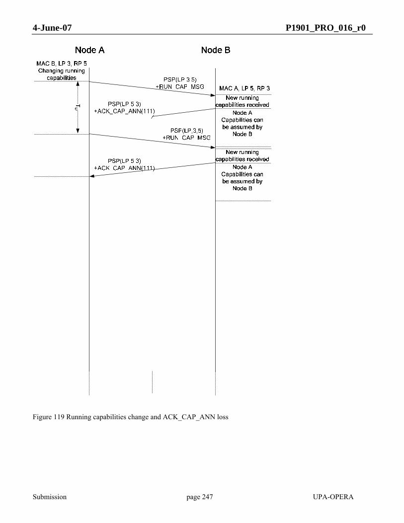
4-June-07 P1901_PRO_016_r0
Submission page 247 UPA-OPERA
Figure 119 Running capabilities change and ACK_CAP_ANN loss
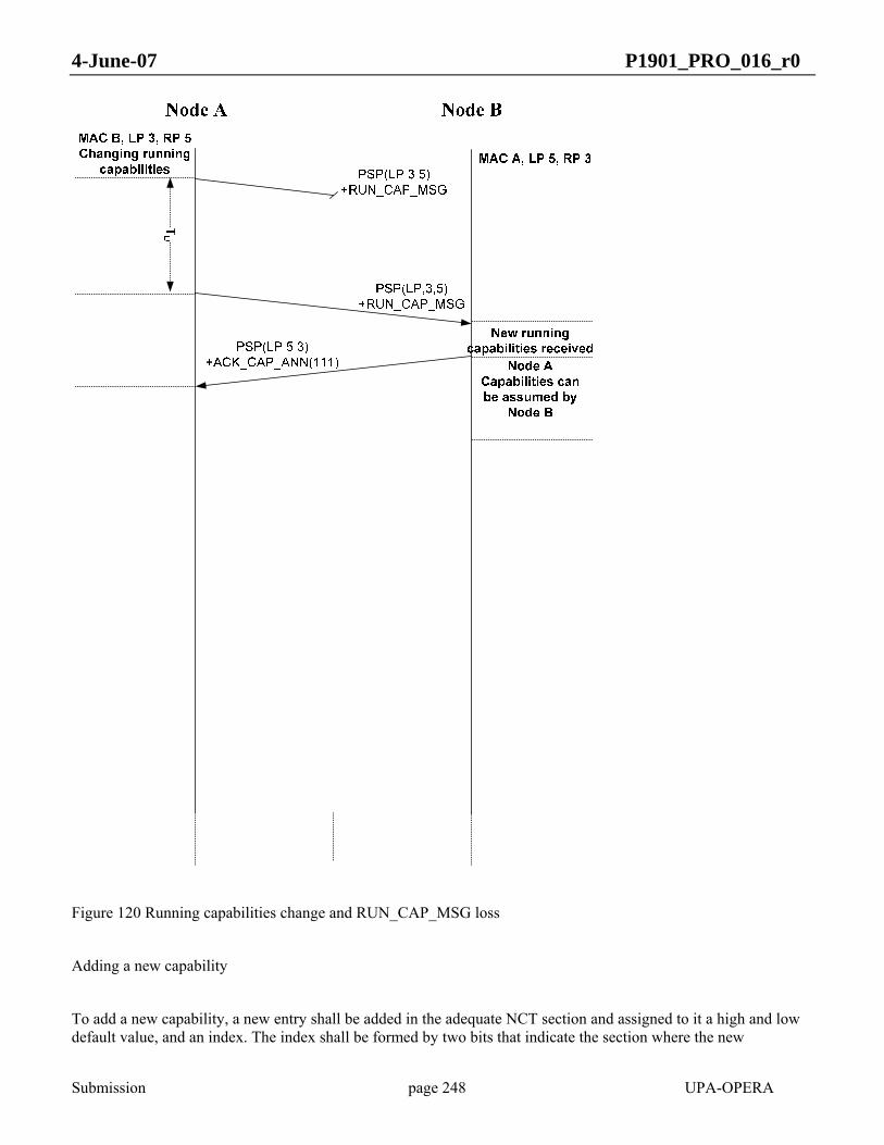
4-June-07 P1901_PRO_016_r0
Submission page 248 UPA-OPERA
Figure 120 Running capabilities change and RUN_CAP_MSG loss
Adding a new capability
To add a new capability, a new entry shall be added in the adequate NCT section and assigned to it a high and low default value, and an index. The index shall be formed by two bits that indicate the section where the new
4-June-07 P1901_PRO_016_r0
Submission page 249 UPA-OPERA
capabilitity is included (Common, Chip, Reference Design or Firmware) and a number that shall be consecutive to the last assigned. In the case of a capability that belongs to a vendor dependent section, it shall be the vendor who assigns a new index number to the new capability. In case of the common section, the new capabilities will be determined by the protocol.
In case the new capability needs more than one byte to inform about its status, this information shall be sent byte by byte with the uniqe filed index preceding each byte.
The new capability shall be sent in the same order that has been assigned in the NCT in the enumerated MAX_CAP_MSG(000) messages, and using its index and section in the RUN_CAP_MSG messages.
Cluster Discovery Protocol
The use of the Cluster Discovery Protocol (from here onwards, CDP) is limited to TDRs. Its use is not mandatory. The non-use of this protocol will result in the impossibility of its master to send non-returnable tokens.
A master must be able to determine if the nodes that are hanging from it may be divided in isolated clusters. In order to achieve this it is necessary for every alive node to transmit information in the upstream direction, in order to know which nodes are visible for each node. This is achieved through the Cluster Discovery Protocol. This protocol also gives information of the exact network topology.
CPEs are already sending the information regarding which nodes are visible with the periodic Announce Messages (see 9.1.4.4). They do not need to send any other information in the upstream.
However, a TDR X needs to send the following information to their masters:
List of nodes that are visible from X (this would be the same as the information in the periodic Announce Message sent by X);
List of nodes that belong to its BPL subtree: this includes CPEs and TDRs which are under the direct or indirect control of X;
List of nodes external to the BPL subtree of X that are visible from all the nodes belonging to its BPL subtree.
In order to transmit the information in points 2 and 3 the Cluster Discovery Protocol is used. This protocol simply consists in the periodic transmission from a TDR to its master of all this information. The information is recursive, because in order to form this packet, the TDR must have previously received the information from its slaves in order to include it.
The protocol will start in the first TDR (the one with only end-users hanging from it), once it has received at least one Periodic Announce Message from all of its slaves. The TDR will recollect this information, and send to its master a new packet. Every TDR in the chain will repeat this. Any TDR as well as the Head End might use the

4-June-07 P1901_PRO_016_r0
Submission page 250 UPA-OPERA
information received to determine that there are isolated clusters, and that it can perform spatial reuse by the use of the non-returnable token (see 4.4.2.9)
Cluster Discovery Protocol message format
The CDP Message is encapsulated using the CCP with Type0 0x0a and Type1 0x01 (Figure 102). The CDP packet will be sent through unicast port, as it is specifically addressed to the master node. The destination MAC will be the master node destination MAC.
Dest MAC Src MAC Payload
0xA
A0x
AA
Cluster Discovery Protocol Data
0x03
0x00
0x0A
Leng
th
0x13
0x9D
0x01
TPID
TCI
Figure 121 Cluster discovery packet format
The information can be fragmented in several packets (identified by a sub-table number) if the entries do not fit in one.
The CDP data fields are:
Bytes CDP data fields Length
0 Sub-table number 1 bytes
1 Number of sub-tables 1 bytes
2 Number of entries of the sub-table 1 byte
3 – 8 Sender MAC address 6 byte
9 Entry size (in bytes) 1 byte
10 - 521 Entries 512 bytes

4-June-07 P1901_PRO_016_r0
Submission page 251 UPA-OPERA
Maximum
Table 39 Cluster discovery packet fields
The Entries in the above table have the following format, although they could be extended:
Table 40 Cluster discovery entries
The Dependency field will be set to 1 if the corresponding MAC belongs to the same BPL subtree. Otherwise, it will be set to 0.
The Cluster Discovery Protocol packet shall be sent at least when changes in the topology and visibility are detected; nevertheless this information can be transmitted periodically.
To increase the packet intelligibility and to simplify the subsequent algorithms, the order of the entries in a sub-table and the order of sub-tables in the CDP packet are predetermined:
In a sub-table, all entries belonging to the same BPL subtree shall appear together and at the beginning of the sub-table, after them, there will be entries with only visibility dependency.
Every TDR shall place its sub-table at the beginning of the CDP packet and encapsulate the CDP packets received from other TDRs, slaves of its, without altering their sub-table order. There is no restriction in the order how the CDP packets received from TDRs belonging to the same hierchary level shall be encapsulated.
Connection Admission Control Protocol (CAC)
The Connection Admission Control Protocol Messages are sent whenever one or several new flow(s) register into the BPL network to reserve the type of traffic that should be assigned, and also when there are changes in the traffic requirements for any of the flows, so that new resources can be committed or released. If reservation parameters change during the duration of the current session, an update of the parameters is necessary.
There are six types of CAC messages:
CAC_Req : Request to the master for the desired resources.
Entry fields Length
MAC address 6 bytes
Dependency 1 byte

4-June-07 P1901_PRO_016_r0
Submission page 252 UPA-OPERA
CAC_Rsp ; Reponse from the master.
CAC_Chg ; Inform the master of a change in the allocated resources.
CAC_Chg_Rsp ; Contains the response to a CAC_Req.
CAC_Drp: Master or Repeater tells a node it shall cancel its reservation.
CAC_Stp: Inform the FMN that a traffic flow has stopped (thus that its resources can be freed).
Flow Master Node (FMN) is defined as the BPL node in charge of guarantee QoS requirement for a registered flow. All CAC_Req messages are transmitted from the source node which request flow to the BPL subcell master of the node. This request may be propagated to the HE, in this situation FMN of the requested flow will be network HE, or could be blocked by an intermediate node if this node decides to be the FMN of the requested flow.
Destination MAC address of CAC messages:
CAC_Req/CAC_Chg/CAC_Stp messages are transmitted by a BPL node and it shall be addressed to its BPL subcell master, these messages will be propagated in the network hop by hop until arrive to the FMN of the flow. These messages have as source MAC the MAC of the node that request the flow and as destination MAC the MAC of the BPL subcell master.
CAC_Rsp/CAC_Chg_Rsp/CAC_Drp messages are transmitted by the FMN in downstream to the node which request the flow. CCP source address will be the MAC of the FMN and the destination MAC, the address of the directly connected slave that is part of the requested flow.
CAC_Req
The CAC_Req message is transmitted to request QoS Resources to be committed in order to satisfy the agreed quality parameters. It may be originated from any node except network HE. There are two subtypes Slave CAC_Req and Master CAC_Req.
CAC_Req sequence is triggered by a CPE or Repeater node upon detection of a specific flow or statically after node configuration. A node requesting resources must trigger a CAC_Req sequence by sending a CAC_Req message to its master node. Master node then decides if can guarantee requested flow and can reply the request with a CAC_Rsp message, in this case Master node will become the FMN of the requested flow (the node that should guarantee flow requirements). In order to guarantee requested flow guarantees, FMN can trigger a new CAC_Req message to its master or use existing resources to guarantee the flow.
If a node decides to be the FMN of a specific user flow, it must be the FMN of the totality of flows for this user.
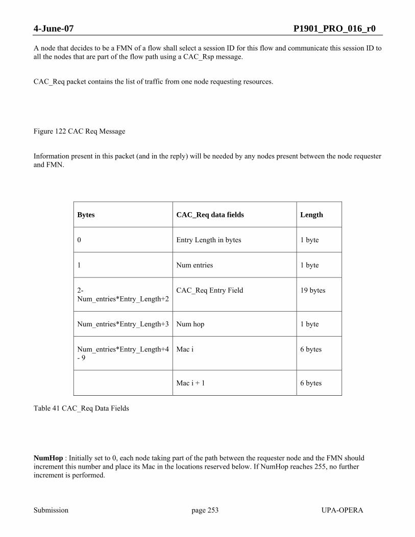
4-June-07 P1901_PRO_016_r0
Submission page 253 UPA-OPERA
A node that decides to be a FMN of a flow shall select a session ID for this flow and communicate this session ID to all the nodes that are part of the flow path using a CAC_Rsp message.
CAC_Req packet contains the list of traffic from one node requesting resources.
Figure 122 CAC Req Message
Information present in this packet (and in the reply) will be needed by any nodes present between the node requester and FMN.
Bytes CAC_Req data fields Length
0 Entry Length in bytes 1 byte
1 Num entries 1 byte
2- Num_entries*Entry_Length+2
CAC_Req Entry Field 19 bytes
Num_entries*Entry_Length+3 Num hop 1 byte
Num_entries*Entry_Length+4 - 9
Mac i 6 bytes
Mac i + 1 6 bytes
Table 41 CAC_Req Data Fields
NumHop : Initially set to 0, each node taking part of the path between the requester node and the FMN should increment this number and place its Mac in the locations reserved below. If NumHop reaches 255, no further increment is performed.

4-June-07 P1901_PRO_016_r0
Submission page 254 UPA-OPERA
Mac i : Macs of nodes taking part of the path from the requester node to the FMN. It is necessary to know the path to send the reply packet from the FMN to the requester node.
Data Field Description Size (Bytes)
Mac SrcReq MAC of the requester node 6
Mac DstReq MAC of the destination traffic flow
6
Request ID MAC source of the request and the request ID form a unique identifier of the request. If a CAC_Req message is lost but resource has been partially allocated in some nodes of the flow path, request should be resent again after a timeout (MAX_CAC_TO). Resources shall not be allocated again.
1
Service Class Service Class of the traffic flow
1
Latency
(ms)
Latency requirements of the flow
2
Bandwidth Bandwidth requested 2
Table 42 CAC_Req Message Entry Field
CAC_Rsp

4-June-07 P1901_PRO_016_r0
Submission page 255 UPA-OPERA
The CAC_Rsp message is transmitted by a FMN to accept or deny requested resources. This packet is sent by the master and is destined to the requester but will go down throughTDRs placed on the way (if they exist).
Figure 123 CAC Rsp Message
The CAC Reservation Response payload must have the following fields:
Bytes CAC_Rsp data fields Length
0 Entry Length in bytes 1 byte
1 Num entries 1 byte
2 - Num_entries*Entry_Length+2
CAC_Rsp Entry Field 19 bytes
Num_entries*Entry_Length+3 Num hop 1 byte
Num_entries*Entry_Length+4 - Num_entries*Entry_Length+9
Mac i 6 bytes
Mac i + 1 6 bytes
Table 43 CAC_Rsp Data Fields

4-June-07 P1901_PRO_016_r0
Submission page 256 UPA-OPERA
And each entry of CAC Reservation Response must have the following fields:
Data Field Description Size (Bytes)
Mac SrcReq MAC of the requester node 6
Mac DstReq MAC of the destination traffic flow
6
Ack Status (accepted or not) of the flow based on calculation of available bandwidth and bandwidth requested.
1
Session ID Session ID assigned to this flow. Used if Ack status is accepted.
1
Service Class Service Class of the traffic flow
1
Latency
(ms)
Latency assigned 2
Bandwidth Bandwidth assigned 2
Table 44 CAC_Rsp Message Entry Field
CAC_Chg

4-June-07 P1901_PRO_016_r0
Submission page 257 UPA-OPERA
CAC_Chg message must be used when:
A resource parameter has changed and the node has to communicate the change to its FMN.
If the FMN receives a Reservation Change from an open Session Id, it updates the resources requested, the FMN has to answer with a Reservation Change Confirmation Packet, indicating if the new resources requested are accepted or not. If the requester node does not receive the acknowledgement of the packet sent, when a timeout expires, it will send a new Reservation Change Packet.
Figure 124 CAC Change Message
The CAC Change payload must have the following fields:
Bytes CAC_Chg data fields Length
0 Entry Length in bytes 1 byte
1 Num Entries 1 byte
2 - Num_entries*Entry_Length+2
CAC_Chg Entry Field 3 bytes
Table 45 CAC_Chg Data Fields

4-June-07 P1901_PRO_016_r0
Submission page 258 UPA-OPERA
And each entry of CAC Change must have the following fields:
Data Field Description Size (Bytes)
Session ID Session ID assigned to this flow.
1
Latency Latency requirements of the flow
1
Bandwidth Bandwidth requested 1
Table 46 CAC_Chg Message Entry Field
CAC_Chg_Rsp
CAC_Chg_Rsp message is sent by the FMN of a flow to communicate if a flow has been correctly allocated.
Figure 125 CAC Change Response Message
The CAC Change payload must have the following fields:

4-June-07 P1901_PRO_016_r0
Submission page 259 UPA-OPERA
Bytes CAC_Chg_Rsp data fields Length
0 Entry Length in bytes 1 byte
1 Num Entries 1 byte
2 - Num_entries*Entry_Length+2
CAC_Chg Entry Field 3 bytes
Table 47 CAC_Chg_Rsp Data Fields
And each entry of CAC Change Response must have the following fields:
Data Field Description Size (Bytes)
Session ID Session ID assigned to this flow.
1
ACK Status (accepted or not) of the flow based on calculation of available bandwidth and bandwidth requested.
1
Latency Latency assigned 2
Bandwidth Bandwidth assigned 2
Table 48 CAC Chg Rsp Entry Fields
CAC_Drp
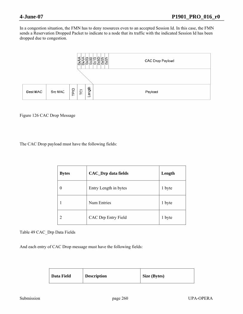
4-June-07 P1901_PRO_016_r0
Submission page 260 UPA-OPERA
In a congestion situation, the FMN has to deny resources even to an accepted Session Id. In this case, the FMN sends a Reservation Dropped Packet to indicate to a node that its traffic with the indicated Session Id has been dropped due to congestion.
Figure 126 CAC Drop Message
The CAC Drop payload must have the following fields:
Bytes CAC_Drp data fields Length
0 Entry Length in bytes 1 byte
1 Num Entries 1 byte
2 CAC Drp Entry Field 1 byte
Table 49 CAC_Drp Data Fields
And each entry of CAC Drop message must have the following fields:
Data Field Description Size (Bytes)
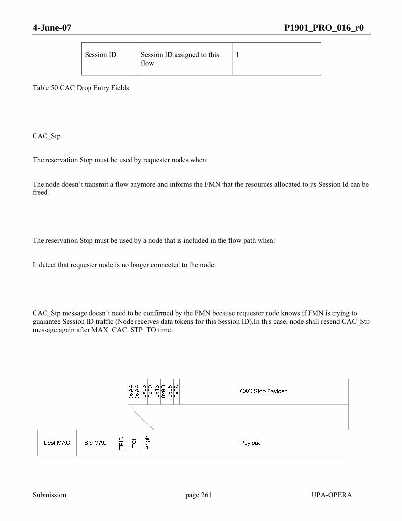
4-June-07 P1901_PRO_016_r0
Submission page 261 UPA-OPERA
Session ID Session ID assigned to this flow.
1
Table 50 CAC Drop Entry Fields
CAC_Stp
The reservation Stop must be used by requester nodes when:
The node doesn’t transmit a flow anymore and informs the FMN that the resources allocated to its Session Id can be freed.
The reservation Stop must be used by a node that is included in the flow path when:
It detect that requester node is no longer connected to the node.
CAC_Stp message doesn´t need to be confirmed by the FMN because requester node knows if FMN is trying to guarantee Session ID traffic (Node receives data tokens for this Session ID).In this case, node shall resend CAC_Stp message again after MAX_CAC_STP_TO time.

4-June-07 P1901_PRO_016_r0
Submission page 262 UPA-OPERA
Figure 127 CAC Stop Message
The CAC Stop payload must have the following fields:
Bytes CAC_Stp data fields Length
0 Entry Length in bytes 1 byte
1 Num Entries 1 byte
2 CAC Stp Entry Field 1 byte
Table 51 CAC Stp Data Fields
And each entry of CAC Stop message must have the following fields:
Data Field Description Size (Bytes)
Session ID Session ID assigned to this flow.
1
Table 52 CAC Stp Entry Fields
Connection Admission Control protocol scenarios.

4-June-07 P1901_PRO_016_r0
Submission page 263 UPA-OPERA
Figure 128 CAC Protocol Scenario 1
¡Error! No se encuentra el origen de la referencia. CPE Request resources to its direct master. REP node propagate CAC_Req message and the Network HE becomes the FMN of the flow. A session ID will be assigned by the HE to the flow in all the flow path.
Figure 129 CAC Protocol Scenario 2
¡Error! No se encuentra el origen de la referencia. REP node receives a CAC_Req message from a CPE. REP node decides to be the FMN of this flow because it has enough resources. CAC_Req message shall not be propagated to the HE.
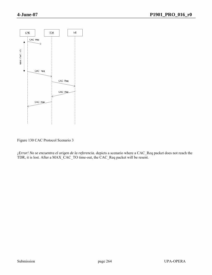
4-June-07 P1901_PRO_016_r0
Submission page 264 UPA-OPERA
Figure 130 CAC Protocol Scenario 3
¡Error! No se encuentra el origen de la referencia. depicts a scenario where a CAC_Req packet does not reach the TDR, it is lost. After a MAX_CAC_TO time-out, the CAC_Req packet will be resent.

4-June-07 P1901_PRO_016_r0
Submission page 265 UPA-OPERA
CPE TDR HE
CAC_Req
CAC_Req
MA
X_C
AC
_TO
CAC_Rsp
CAC_Rsp
CAC_Req
CAC_Rsp
Figure 131 CAC Protocol Scenario 4
Figure 131 Resources are partially allocated for a session ID. CAC_Req message shall be resent after MAX_CAC_TO timeout but REP shall not resend it because REP resources have been allocated previously, and TDREP must send the CAC_Rsp with the session_id to the node

4-June-07 P1901_PRO_016_r0
Submission page 266 UPA-OPERA
CPE TDR HE
CAC_Req
CAC_Req
CAC_Rsp
CAC_Rsp
CAC_Stp
CAC_Stp
Figure 132 CAC Protocol Scenario 5
Figure 132 Resources may be freed using CAC_Stp message. Message shall be propagated to FMN.

4-June-07 P1901_PRO_016_r0
Submission page 267 UPA-OPERA
CPE TDR HE
CAC_Req
CAC_Req
CAC_Rsp
CAC_Rsp
CAC_Stp
CAC_Stp
CAC_Stp
MAX
_CAC
_STP
_TO
Figure 133 CAC Protocol Scenario 6
Figure 133 Resources may be freed using CAC_Stp message. If Message CAC_Stp is lost. message shall be resent after MAC_CAC_STP_TO time if node is still receiving requested resource.

4-June-07 P1901_PRO_016_r0
Submission page 268 UPA-OPERA
CPE TDR HE
CAC_Req
CAC_Req
CAC_Rsp
CAC_Rsp
CAC_Stp
TDR detect CPE is disconnected
Figure 134 CAC Protocol Scenario 7
Figure 134 REP node detect a node is no longer connected. It shall free all resources allocated for the node subcell.
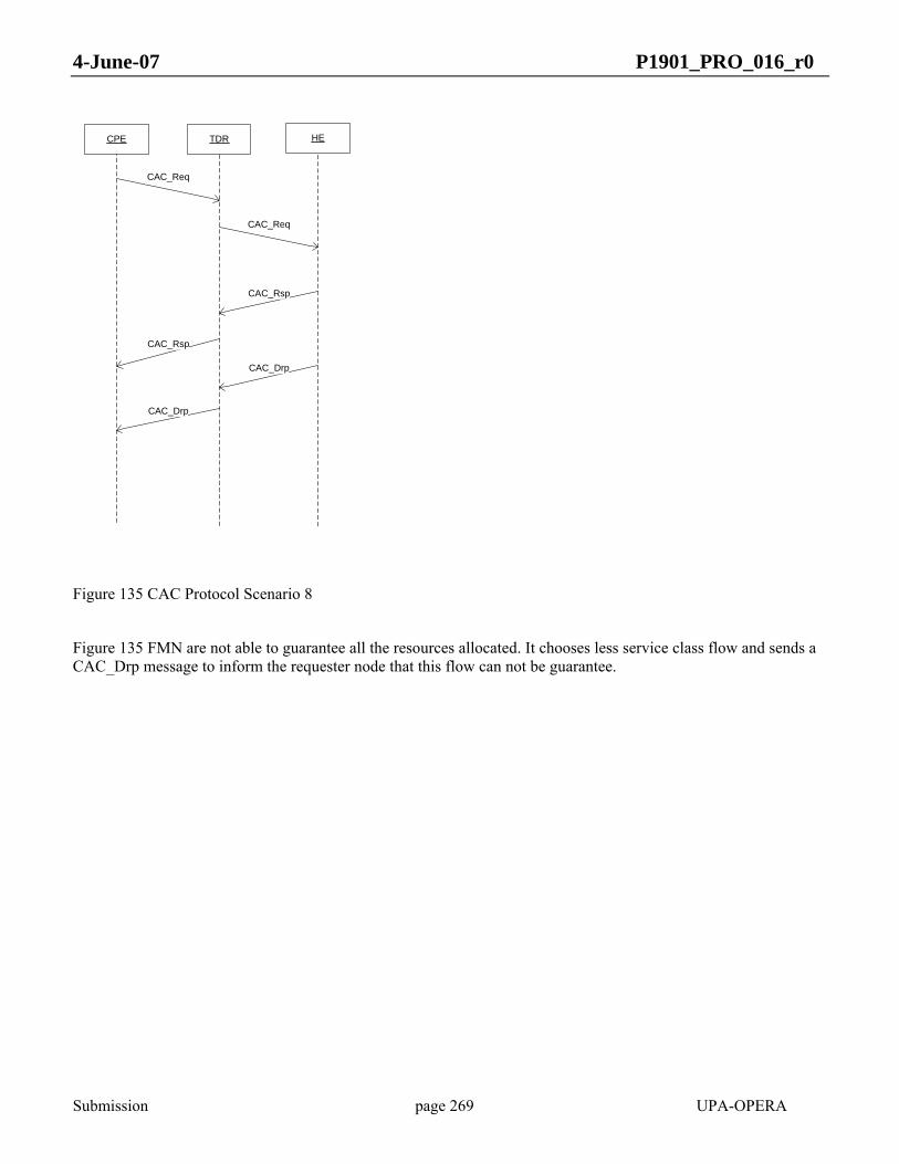
4-June-07 P1901_PRO_016_r0
Submission page 269 UPA-OPERA
CPE TDR HE
CAC_Req
CAC_Req
CAC_Rsp
CAC_Rsp
CAC_Drp
CAC_Drp
Figure 135 CAC Protocol Scenario 8
Figure 135 FMN are not able to guarantee all the resources allocated. It chooses less service class flow and sends a CAC_Drp message to inform the requester node that this flow can not be guarantee.

4-June-07 P1901_PRO_016_r0
Submission page 270 UPA-OPERA
CPE TDR HE
CAC_Req
CAC_Req
CAC_Rsp
CAC_Rsp
CAC_Drp
CAC_Drp
MAX
_CAC
_DR
P_TO
Figure 136 CAC Protocol Scenario 9
Figure 136 CAC_Drp message is lost. CPE node will deregister flow after MAX_CAC_DRP_TO time without receiving the resource (Tokens with a register Session ID).
Automatic Management of Crosstalks between not Synchronized Systems
This section describes a mechanism to avoid crosstalk that may be implemented but is not mandatory.
Once the nodes realize that there is more than one master in the channel by means of the Master Id (see 4.4.1), it is necessary to take some measures to avoid such interferences.
The solution is to coordinate both BPL cells, and the simplest way to do it is subordinate one of the BPL cells. Next, the algorithm is explained:
MID hierarchy
When the crosstalk is detected, then the nodes must decide which BPL cell must subordinate.

4-June-07 P1901_PRO_016_r0
Submission page 271 UPA-OPERA
The rule shall be “the lowest MID, the best”, analyzing the MID as a number.
Then, one of the nodes of the worse BPL cell will register in the neighbor network using the Access Protocol, and it will act as master of its BPL cell, distributing the token.
If one node does not perform this protocol it does not copy the MID inherited from its master, instead it fixes the local MID to one of these values:
0x1FFFFF. Nodes that have not completed the Access Protocol.
0x130001. Nodes that have finished the Access Protocol.
Border node designation
The border node is the modem that will act as a bridge between the networks passing the token.
Once the interference is detected, the network with higher MID must decide which node within the BPL cell, will perform registration.
Designation Rules
The master will select the Border Node with the following criteria:
Less hops, higher priority. This is, if the interference is detected by several nodes, the HE has preference over the rest of the nodes; next TDRs placed one hop away; next repeaters with two hops, etc.
CPEs do not perform this protocol, only HEs and TDRs do. A node that detects only a CPE of a neighbor BPL cell does not apply for becoming border node.
Notification protocol
To centralize the decision, the HE of the BPL cell decides which node will perform negotiation, interchanging CCP packets. Since the interference will not be detected by all the nodes simultaneously, a guard time may be kept before designating the border node in order to know all the information.
If any node detects the interference (sniffing a better MID), it transmits an Interference Detection Packet (IDP), containing the own MAC, the neighbor MAC sniffed, the MID sniffed, the local number of hops and the identity of the node detected (HE or TDR). When the packet is received by a node, it has to check if is coming from one of its slaves, then the information is copied and retransmitted to its master, then the packet will arrive finally to the HE of the BPL cell. To avoid flooding the network, the IDPs have to be sent with a minimum period of 10 seconds
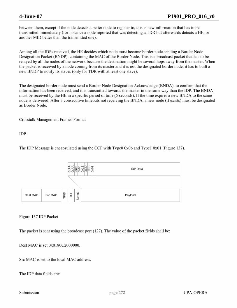
4-June-07 P1901_PRO_016_r0
Submission page 272 UPA-OPERA
between them, except if the node detects a better node to register to, this is new information that has to be transmitted immediately (for instance a node reported that was detecting a TDR but afterwards detects a HE, or another MID better than the transmitted one).
Among all the IDPs received, the HE decides which node must become border node sending a Border Node Designation Packet (BNDP), containing the MAC of the Border Node. This is a broadcast packet that has to be relayed by all the nodes of the network because the destination might be several hops away from the master. When the packet is received by a node coming from its master and it is not the designated border node, it has to built a new BNDP to notify its slaves (only for TDR with at least one slave).
The designated border node must send a Border Node Designation Acknowledge (BNDA), to confirm that the information has been received, and it is transmitted towards the master in the same way than the IDP. The BNDA must be received by the HE in a specific period of time (5 seconds). If the time expires a new BNDA to the same node is delivered. After 3 consecutive timeouts not receiving the BNDA, a new node (if exists) must be designated as Border Node.
Crosstalk Management Frames Format
IDP
The IDP Message is encapsulated using the CCP with Type0 0x0b and Type1 0x01 (Figure 137).
Dest MAC Src MAC Payload
0xA
A0x
AA
IDP Data
0x03
0x00
0x0B
Leng
th
0x13
0x9D
0x01
TPID
TCI
Figure 137 IDP Packet
The packet is sent using the broadcast port (127). The value of the packet fields shall be:
Dest MAC is set 0x0180C2000000.
Src MAC is set to the local MAC address.
The IDP data fields are:
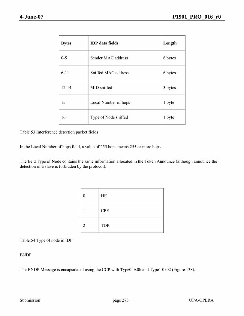
4-June-07 P1901_PRO_016_r0
Submission page 273 UPA-OPERA
Bytes IDP data fields Length
0-5 Sender MAC address 6 bytes
6-11 Sniffed MAC address 6 bytes
12-14 MID sniffed 3 bytes
15 Local Number of hops 1 byte
16 Type of Node sniffed 1 byte
Table 53 Interference detection packet fields
In the Local Number of hops field, a value of 255 hops means 255 or more hops.
The field Type of Node contains the same information allocated in the Token Announce (although announce the detection of a slave is forbidden by the protocol).
0 HE
1 CPE
2 TDR
Table 54 Type of node in IDP
BNDP
The BNDP Message is encapsulated using the CCP with Type0 0x0b and Type1 0x02 (Figure 138).

4-June-07 P1901_PRO_016_r0
Submission page 274 UPA-OPERA
Dest MAC Src MAC Payload
0xA
A0x
AA
BNDP Data
0x03
0x00
0x0B
Leng
th
0x13
0x9D
0x02
TPID
TCI
Figure 138 BNDP Packet
The packet is sent using the broadcast port (127). The value of the packet fields shall be:
Dest MAC is set 0x0180C2000000.
Src MAC is set to the local MAC address.
The BNDP data fields are:
Bytes BNDP data fields Length
0-5 Border Node MAC address 6 bytes
Table 55 BNDP packet fields
BNDA
The BNDA Message is encapsulated using the CCP with type 0x0b and subtype 0x03 (Figure 139).
Dest MAC Src MAC Payload
0xA
A0x
AA
BNDA Data
0x03
0x00
0x0B
Leng
th
0x13
0x9D
0x03
TPID
TCI

4-June-07 P1901_PRO_016_r0
Submission page 275 UPA-OPERA
Figure 139 BNDA Packet
The packet is sent using the broadcast port (127). The value of the packet fields shall be:
Dest MAC is set 0x0180C2000000.
Src MAC is set to the local MAC address.
The BNDA data fields are:
Bytes BNDA data fields Length
0-5 Border Node MAC address 6 bytes
Table 56 BNDA packet fields
Border node registration
Once the border node is designated by the HE (can be itself), it starts its attempt for registration in the neighbor BPL cell as it is described in the Access Protocol.
Master selection
The border node will select the master to register based in the following criteria:
First HE (of the neighbor BPL cell)
Second repeaters.
Successful registration
If the modem succeeds, as it has changed BPL cell it copies the MID of its new BPL cell, in this way any node knows that the node is token dependant from the neighbor network.
4-June-07 P1901_PRO_016_r0
Submission page 276 UPA-OPERA
A node performing the registration in the neighbor BPL cell will have a MID different and it will be different from 0x1FFFFF and 0x130001. Under these conditions the node must be accepted avoiding any authentication process, also the master node knows that is not a node from its network and must avoid transmit any data through the BPL port.
Failing registration
The maximum time specified for the registration of the border node is 120 seconds
When the timer expires, the HE has to select a new border node to complete negotiation. The HE is the node that monitories the registration timer, in this way no new packets are needed, even if the border node designated is switched off the HE restarts the protocol by itself.
The formerly designated border node has to activate the registration timer like the master and when the timer expires it assumes that it is not border node anymore until a new BNDP is received.
Intermittent transmission
To perform successfully the negotiation among BPL cells it is necessary to get free interference periods, because the transmissions within the own BPL cell will ruin the registration.
A HE can decide by itself to stop the transmissions within its network avoiding new token generation, but any other node cannot because its master will regenerate the token.
When the HE receives a BNDA it starts a period so called “INTERMITTENT TRANSMISSION” [IT].
During the status of Border Node a modem can generate as many BNDAs as needed to complete the negotiation.
The default silence time 2 sec, followed by a normal transmission period of 1 sec. It will have 5 silence periods. So the overall IT will last 15 seconds.
SPANNING TREE
In a network, a spanning tree is a path or collection of paths that represent connections between nodes. To be called a spanning tree, the tree must cover every possible path in a network. A minimal spanning tree is one that covers all possible paths, does so with as few segments as possible, and makes sure there are no loops (closed paths) in the network.
The IEEE 802.1 recommendations provide an algorithm for finding a spanning tree in any network.

4-June-07 P1901_PRO_016_r0
Submission page 277 UPA-OPERA
STP packets will be transmitted through the corresponding unicast ports.
IEEE 802.1D (Spanning Tree Protocol)
The 802.1D recommendation describes the Spanning Tree algorithm and protocol. In this document, the calculation of the tree elements and the messages exchanged between bridges for this purpose are exposed. This specification is fully compliant with this standard.
The implementation of IEEE 802.1D is a must for network compatibility.
For specific information on message types and their fields and the algorithm to handle them, refer to IEEE Std 802.1 and IEEE Std 802.1D (Spanning Tree).
Ports can be Ethernet or BPL. Every new BPL connection is added to the bridge as a new port. Ports can be deleted when the BPL connection is lost for some physical reason. Some ports, such as Ethernet ports, are always present. Each port carries out the STP.
Default timers and field values
The IEEE recommendation is relatively flexible in some aspects, such as default timer values and other message fields, so that they can be tuned for different network sizes and Medium Access technologies. The values adopted by this specification for these parameters are:
hello: time between each BPDU that is sent on a port.
Default: 2 seconds
Range: [1, 10] seconds
forward delay: time spent in the listening and learning states.
Default: 15 seconds
Range: [4, 30] seconds
max age: maximum length of time a bridge port saves its configuration.
Default: 20 seconds

4-June-07 P1901_PRO_016_r0
Submission page 278 UPA-OPERA
Range: [6, 40] seconds
Priority: The greater the number, the less priority.
MV Master 0x9010
MV Repeater 0x9020
LV Master 0x9030
LV Repeater 0x9040
LV Slave 0x9050
Table 57 STP priority
IEEE 802.1w (Rapid STP)
Rapid Spanning Tree Protocol (RSTP; IEEE 802.1w) is an amendment to 802.1D. This version offers a significant reduction in the time taken to reconfigure the active topology of the Bridged LAN in the face of changes to the physical topology or its configuration parameters. The strategy to reach this performance is based on a handshake mechanism between bridges that enables a fast transition to forwarding, thus bypassing the listening and learning states and timers.
The two versions of the algorithm and protocol are capable of interoperating within the same Bridged LAN; hence, it is not necessary for implementations to support both versions of the Spanning Tree algorithm and protocol.
In view of the improved performance offered, it is recommended that the Rapid Spanning Tree algorithm and Protocol be supported in preference to the original version.
For specific information on message types and their format, the migration protocol and the RSTP algorithm, refer to IEEE Std 802.1D, 1998 Edition; Clause 17 (Rapid Spanning Tree Algorithm and Protocol), also found as 802.1w.
Default timers and field values
migration delay (mdelay): indicates that the protocol migration is ongoing. It is used to avoid re-entry. If any BPDU of the other type is received while mdelay is running, it is ignored in terms of protocol migration. mdelay is set to 3 seconds.

4-June-07 P1901_PRO_016_r0
Submission page 279 UPA-OPERA
Point-to-point ports and edge ports
In order to achieve fast convergence on a port, the protocol relies upon two new variables: edge ports and link type.
All BPL ports can be assumed to be point-to-point ports. Ethernet ports can be considered edge ports, unless another bridge is connected to the same segment. Anyway, since the standard establishes that the first BPDU coming into an edge port removes its edge port status, it can be assumed at startup that all ports are candidate to directly transition to forwarding:
Ethernet ports start in forwarding state (edge ports).
BPL ports, even though they start in blocking state, are ready for handshake and rapid transition to forwarding (point-to-point).
STP and VLANs
If VLANs are active, STP packets must use the management VLAN inside the power-line network.
Common STP
Ethernet interfaces must support the possibility of being configured to remove/add the VLAN tag to the outgoing/incoming STP packets. That is, the VLAN tag of the STP packets going out the BPL network is removed. On the other hand, VLAN tag must be added to the incoming STP packets, so as to make sure that STP packets inside the power-line network use the management VLAN.
10 SECURITY
10.1 LOW LEVEL ENCRYPTION AND INTEGRITY
10.1.1 Overview
Encryption and Integrity are two key features needed by any communication device to guarantee security and privacy in the message exchange.
For encryption IEEE P1901 uses as basic building block the Advanced Encryption Standard (AES) according to FIPS-97(2002).
AES is a block cipher algorithm while higher layers have to deal with variable length packets. To be able to encrypt these variable length packets IEEE P1901 uses the operation mode known as Counter Mode (CTR) defined in

4-June-07 P1901_PRO_016_r0
Submission page 280 UPA-OPERA
NIST800-38A “Recommendations for Block Cipher Modes of Operation. Methods and Techniques”. By the use of CTR IEEE P1901 achieves confidentiality for messages of arbitrary length.
Nevertheless it is still necessary to provide message integrity against tampering. For this purpose IEEE P1901 uses the operation mode known as CCM (Counter with CBC-MAC (Message Authentication Check)) that avoids the use of a separate mechanism for providing message integrity. CCM mode of operation combines CTR mode of encryption with the CBC-MAC mode of authentication. CCM is defined in RFC 3610 and has been used and studied for a long time and has well-understood cryptographic properties. The interesting point is that the same encryption key can be used for both processes in conjunction with other parameters, thus leading, in effect, to two separated keys.
CCM is only defined for 128-bit block ciphers and, though it is a generic mode applicable to any many ciphers, in IETF RFC3610 it is defined for use with 128-bit AES.
CCM has two parameters (M and L). M indicates the length of the MIC (Message Integrity Check) and L indicates the length of the message itself. For the selected algorithm M is equal to 4 (thus indicating that the Message Integrity Check (MIC) produced is 4 bytes long) and L is equal to 2 (thus indicating that the length of the message is at most 2^16 bytes as is exactly the maximum length of a burst).
Encryption and Integrity are both based on AES blocks and needs a different initialization variables and modes to work. The information about the initial state for desencryption and integrity check is transported in the CCMP Header.
Encryption and Integrity are applied when the burst is set as encrypted and over each one of the packets or packet fragments inside the burst payload independently, but using the common initial state contained in the CCMP Header, that is transmitted only once each burst at the beginning of the payload.
Each MIC is calculated over the Burst Header, CCMP Header, the Interpacket Header added by the LLC layer and the packet or fragment of a packet including the padding, and then appended to this structure, althought Burst Header and CCMP Header are only transmitted once at the beginning of the Burst.
The encryption algorithm is also applied in a fragment packet or packet basis. Burst Header, CCMP Header and Interpacket Headers shall be sent in clear, and the encryption is applied over the fragment packet or packet including its padding and the appended MIC.
10.1.2 Detailed encryption process
As has been described before, Encryption and Integrity algorithms are applied in a packet or fragment of packet basis, but using common initial state information for each Burst contained in the CCMP Header.
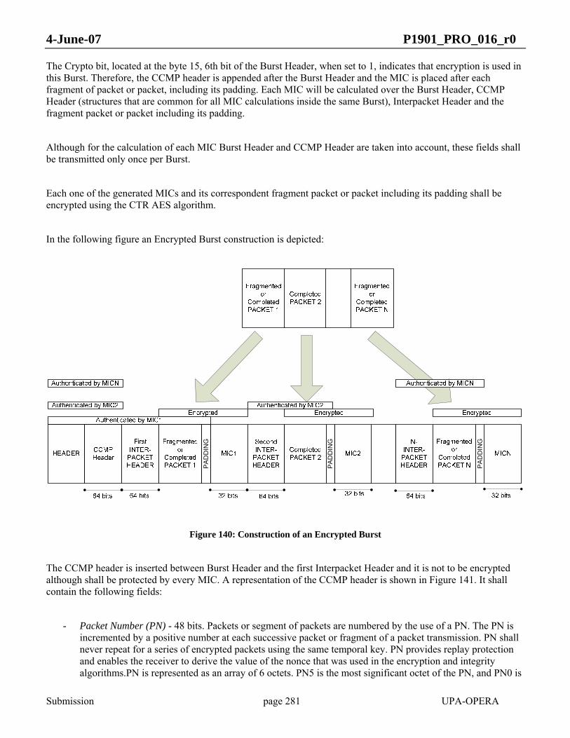
4-June-07 P1901_PRO_016_r0
Submission page 281 UPA-OPERA
The Crypto bit, located at the byte 15, 6th bit of the Burst Header, when set to 1, indicates that encryption is used in this Burst. Therefore, the CCMP header is appended after the Burst Header and the MIC is placed after each fragment of packet or packet, including its padding. Each MIC will be calculated over the Burst Header, CCMP Header (structures that are common for all MIC calculations inside the same Burst), Interpacket Header and the fragment packet or packet including its padding.
Although for the calculation of each MIC Burst Header and CCMP Header are taken into account, these fields shall be transmitted only once per Burst.
Each one of the generated MICs and its correspondent fragment packet or packet including its padding shall be encrypted using the CTR AES algorithm.
In the following figure an Encrypted Burst construction is depicted:
PAD
DIN
G
PA
DD
ING
PA
DD
ING
Figure 140: Construction of an Encrypted Burst
The CCMP header is inserted between Burst Header and the first Interpacket Header and it is not to be encrypted although shall be protected by every MIC. A representation of the CCMP header is shown in Figure 141. It shall contain the following fields:
- Packet Number (PN) - 48 bits. Packets or segment of packets are numbered by the use of a PN. The PN is incremented by a positive number at each successive packet or fragment of a packet transmission. PN shall never repeat for a series of encrypted packets using the same temporal key. PN provides replay protection and enables the receiver to derive the value of the nonce that was used in the encryption and integrity algorithms.PN is represented as an array of 6 octets. PN5 is the most significant octet of the PN, and PN0 is

4-June-07 P1901_PRO_016_r0
Submission page 282 UPA-OPERA
the least significant. The Packet Number sent in the CCMP Header is the one correspondent to the first packet or fragment of a packet sent in the Burst.
- Rsvd – 8 bits. Reserved bits set to 0 and ignored on reception.
- KeyID - 8 bits. 5 bits are reserved and set to 0. Bit 5 is set to 1. Bits 6–7 of the Key ID octet are for the Key ID subfield. The Key ID subfield allows for operating with different keys.
The CCMP Header shall be the following structure:
PN0 PN1 Rsvd KeyID PN2 PN3 PN4 PN5
Rsvd 1 KeyID
1 byte
1 bit
b0 b4 b5 b6 b7
Figure 141: CCMP Header Structure
CCM requires for encryption and message integrity checking, an unique Nonce value, a number which never repeats during a given life time, for each packet protected by a given temporal key. CCM requires a fresh temporal key for every session.
The PN is combined with other fields to produce a 13-octet long Nonce as corresponds to setting the parameter L to 2 as indicated in IETF RFC 3610. This Nonce is represented in Figure 142.

4-June-07 P1901_PRO_016_r0
Submission page 283 UPA-OPERA
Figure 142: Nonce Structure
The Nonce shall be the following fields:
- Nonce priority – 8 bits. This field is different from the priority field in the burst header and is for future capability. The Nonce Priority Octet field shall be 0 and is reserved for future use.
- Source Address – 48 bits. It is taken from the MAC address of the transmitter included in the Token Announce (Section 4.4.1).
- PN – 48 bits. It is calculated adding to the PN of the CCMP Header the number of the first packet or fragment of packet of the Burst minus one.
This Nonce is used to produce two 128-bit words: B0 and A0 (IETF RFC 3610 and NIST 800-38c).
The initial CCMP block B0 (128-bit block), needed for the calculation of the MIC, has the following fields:
- Flag B0 – 8 bits. Fix content (IETF RFC 3610 and and NIST 800-38c). It indicates that the MIC is 32 bits long. See Table 58.
- Nonce – 104 bits. See Figure 142
- DLen – 16 bits. Length in bytes of the data to be encrypted. The DLen is the taken from the Length field of the Inter Packet Header (Figure 58).
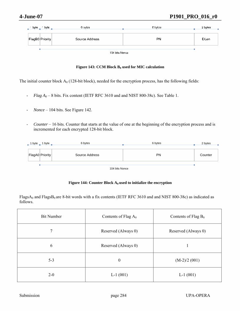
4-June-07 P1901_PRO_016_r0
Submission page 284 UPA-OPERA
Figure 143: CCM Block B0 used for MIC calculation
The initial counter block A0 (128-bit block), needed for the encryption process, has the following fields:
- Flag A0 – 8 bits. Fix content (IETF RFC 3610 and and NIST 800-38c). See Table 1.
- Nonce – 104 bits. See Figure 142.
- Counter – 16 bits. Counter that starts at the value of one at the beginning of the encryption process and is incremented for each encrypted 128-bit block.
Priority Source Address PN
6 bytes 6 bytes
104 bits Nonce
1 byte
FlagA0
1 byte
Counter
2 bytes
Figure 144: Counter Block A0 used to initialize the encryption
FlagsA0 and FlagsB0 are 8-bit words with a fix contents (IETF RFC 3610 and and NIST 800-38c) as indicated as follows.
Bit Number Contents of Flag A0 Contents of Flag B0
7 Reserved (Always 0) Reserved (Always 0)
6 Reserved (Always 0) 1
5-3 0 (M-2)/2 (001)
2-0 L-1 (001) L-1 (001)

4-June-07 P1901_PRO_016_r0
Submission page 285 UPA-OPERA
Table 58: Flag A0 and B0 Contents
The Burst Header, CCMP header and Interpacket Headers shall be transmitted unencrypted. In the calculation of each MIC, the Burst Header plus the CCMP header and the Interpacket Header are more than 128 bits long. Because of this fact, it is necessary, for the proper calculation of the first MIC, to add some padding at the end of the Interpacket Header to get three 128-bit blocks. The padding bits shall not be transmitted. This padding is only used for MIC calculation. Padding bits are not used for encryption. The procedure is shown in Figure 145.
Figure 145: Encryption and Integrity process for the first packet
In the case of the second and subsequent packets, the MIC calculation shall remain the same, but in the encryption, the Burst Header and CCMP Header will not be included in the resulting Encrypted message. The padding bits shall not be transmitted. This padding is only used for MIC calculation. Padding bits are not used for encryption. The procedure is shown in Figure 146.

4-June-07 P1901_PRO_016_r0
Submission page 286 UPA-OPERA
Figure 146: Encryption and Integrity process for all but the first packet
The MIC is computed in both cases using CBC-MAC, which encrypts a starting block B0 and then successively XORs subsequent blocks and encrypts the result. Although the result is a MIC of 128 bits, the lower 96 bits are discarded, and a final 32-bit MIC is obtained.
Once the MIC has been computed and appended to the plaintext data, the encryption takes place using Counter Mode (CTR).
10.2 AAA protocol
In section 9.1.3 the access method used in IEEE P1901 has been described. Nevertheless, for the sake of security, section 9.1.3 is to be complemented with the AAA protocol that is described in the present section.
The access and authentication control system of IEEE P1901 follows closely the one described in IEEE802.1X which in turn relies on the Extensible Authentication Protocol (EAP) [RFC3748] over LAN (EAPOL). IEEE802.1X provides the description of EAPOL.
The purpose of IEEE 802.1X is to implement access control at the point at which a user joins the network. In the process of application of IEEE 802.1X the network entities can take one of three roles: Supplicant, Authenticator and Authentication Server (AS).
The device asking for connection to the network is known as the Supplicant and in IEEE P1901 can be either a CPE or a TDR. The Authenticator can be either the HE or a TDR. The Authentication Server will normally be centralized.
The IEEE 802.1X access control mechanisms apply to the association between a CPE or TDR and a Master.

4-June-07 P1901_PRO_016_r0
Submission page 287 UPA-OPERA
In IEEE 802.1X an access and authentication dialog is defined for the case of authenticator initiated exchange. This dialog is formed by the following sequence of messages:
• Message A: Authenticator to Supplicant
o EAPOL with Code field: Request (1) and Type field: Identity (1)
• Message B: Supplicant to Authenticator
o EAPOL with Code field: Response (2) and Type field: Identity (1)
• Message C: Authenticator to Supplicant
o EAPOL with Code field: Request (1) and Type field: Challenge (4)
• Message D: Supplicant to Authenticator
o EAPOL with Code field: Response (2) and Type field: Challenge (4)
• Message E: Authenticator to Supplicant
o EAPOL with Code field: Success (3) or Failure (4)
In IEEE P1901 Message A of the previous dialog should be implemented by the use of the Access Frame described in section 4.3.8., Message B should be implemented by the use of the Access Reply Frame described in section 4.3.9 and Message E should be implemented by the use of the Access Protocol Packet described in section 9.1.3.
Messages C and D serve for the purpose of authentication. With message C the Authenticator sends a random challenge of 16 octets to the Supplicant and message D is the response of the Supplicant to this challenge. This Response is a 16-octet MD5 hash calculated over the random challenge and the secret shared by the Supplicant and the Authentication Server and other fields [RFC 2865]. This secret should be the Serial Number of the Supplicant.
IEEE 802.1X states that “The EAPOL encapsulation used with IEEE802.3/Ethernet can be applied to other LAN technologies that share the same basic frame format as Ethernet” as is the case of IEEE P1901 technology. As a consequence, the format of Messages C and D in IEEE P1901, which follows the rules of EAPOL packets, are encapsulated in CLPDUs. The formats are the following:

4-June-07 P1901_PRO_016_r0
Submission page 288 UPA-OPERA
Description Nr. Of octets Contents
PAE Ethernet Type 2 0x88-8E
EAPOL Protocol Version 1 0x02
Packet Body Length 2 0x007F
Code 1 Message C: Request (1)Message D: Response (2)
Identifier 1 Requests must modify the IdentifierResponses must match them
Length in octets 2 0x007F
Type 1 Default: 0x04 (MD5 Challenge)Open to other hash functions
Value size 1 Default: 0x10
Value Default: 16
Message C: Random NumberMessage D: Hash
Pac
ket B
ody
Table 59: Message C and D format
This content is included in the payload of a CCP packet.
All of the previous messages, except for Message A, have to be transferred from the Authenticator to the AS or the other way around. This transfer is done in IEEE P1901 by the use of EAP over Radius [RFC 3579] although Radius as a server [RFC2865] does not form part of this specification.
The Format of the EAP over Radius messages follows completely the standard [ RFC2865] [RFC3579].
The IEEE P1901 Access Reply Frame is converted into a “Radius Access-Request/EAP” packet. From the Access Reply Frame the Authenticator creates a standardized EAP-Response /Identity packet and encapsulates it within a RADIUS Access-Request packet.

4-June-07 P1901_PRO_016_r0
Submission page 289 UPA-OPERA
The format of this EAP-Response/Identity packet to be encapsulated in the RADIUS Access-Request is the already indicated for Messages C and D but the Packet Body is the following:
Description Nr. Of octets Contents
Code 1 Response (0x02)
Identifier 1 Requests must modify the IdentifierResponses must match them
Length in octets 2 0x000C
Type 1 0x01 (Identity)
Value size 1 0x06
Value 6 MAC Address of the supplicant
Pac
ket B
ody
Table 60: Packet Body Format for EAP-Response/Identity packet fro messages C and D
The Response to the previous message by the AS is an “Access-Challenge/EAP” packet which the authenticator will convert into Message C for transmission to the Supplicant just decapsulating it.
Message D (EAP-Response/Challenge) shall be encapsulated by the Authenticator into a RADIUS Access-Request/EAP.
And the response to the previous message will be a “Radius Access-Accept (or Reject)/EAP” packet which the authenticator will convert into Message E for transmission to the Supplicant by forming an IEEE P1901 “Access Protocol Packet” as indicated in section 9.1.3, which has also the possibility to signal “Failed” besides Accept or Reject. This would happen in case of failure of the dialog between the Authenticator and the Authentication Server.
The Format of the RADIUS packet encapsulating an EAP message is the following [RFC2865]:

4-June-07 P1901_PRO_016_r0
Submission page 290 UPA-OPERA
Attr
ibut
eA
ttrib
ute
Table 61: RADIUS packet encapsulating an EAP message
In the case of Radius Access-Request/EAP packet it is necessary to add to the previous message structure the following Attributes:

4-June-07 P1901_PRO_016_r0
Submission page 291 UPA-OPERA
Attr
ibut
eA
ttrib
ute
Attr
ibut
e
Table 62: RADIUS Access-request/EAP Attributes
The User Name Attribute must be sent even if the String is already included in the EAP Attribute. This last Attribute must [RFC3579 ]also be included in the Access-Accept.
Exactly one RADIUS packet is encapsulated in the UDP Data field, where the UDP Destination Port field indicates 1812 (decimal). When a reply is generated, the source and destination ports are reversed.
Figure 147 is a representation of the access and authentication dialog used in IEEE P1901.

4-June-07 P1901_PRO_016_r0
Submission page 292 UPA-OPERA
Figure 147: Representation of the access and authentication dialog used in IEEE P1901.
At the end of the dialog the Supplicant is already authenticated but the keys for encryption and for integrity checking are still not established. This is the subject of the next section.
10.3 Key Hierarchies
There are two key hierarchies in IEEE P1901: Pairwise Key Hierarchy and Group Key Hierarchy.
It is assumed that there is a Pairwise Master Key (PMK) that is assumed to be in possession of the Supplicant and the Authenticator by some “out of band means” and which distribution is not the subject of this specification, and a Group Master Key (GMK) which is generated at random by the HE or by some other higher level entity.
From the PMK the following temporal keys are derived for use in conjunction with the AES-CCMP algorithm:
- Data Encryption/Integrity key (128 bits)
- EAPOL-Key Encryption key (128 bits)

4-June-07 P1901_PRO_016_r0
Submission page 293 UPA-OPERA
- EAPOL-Key Integrity key (128 bits)
From the GMK the following temporal key is derived:
- Group Encryption/Integrity key (128 bits)
The EAPOL keys are used to protect key handshakes.
These hierarchies are conformant to the standard IEEE802.11i.
10.4 Establishing the keys
To compute the Pairwise Temporal Keys (PTK) the 4-Way Handshake is used [IEEE 802.11i].
As indicated in Figure 148 the procedure implies the use of 4 messages that use the EAPOL-key format
Figure 148: Schematics of the 4-way handshake

4-June-07 P1901_PRO_016_r0
Submission page 294 UPA-OPERA
In this dialog Supplicant and Master exchange two Nonces that allow to derive the PTK; Supplicant and Authenticator prove knowledge of the PMK to the other one and both synchronize to turn on the encryption keys for unicast packets. Message 3 may also be used to send the GTK (Group Transient Key).By this way the Supplicant and the Authenticator have established a secure channel using encryption in both directions.
11 SYSTEM PARAMETERS
11.1 GENERAL PARAMETERS
• GENERAL_USE_AUTOCONF = [YES | NO]
Parameter: YES enables autoconf, NO disables it.
SNMP: no
Mandatory: yes
This should be the first parameter in the auto-configuration file. If this parameter is disabled, when downloading the file, all the parameters will be stored in non-volatile memory, and next boot-up will be in local settings boot mode. In case of enabled, except a few parameters that must be necessarily saved in non-volatile memory, the others will not be stored in the non-volatile memory, and next boot-up will be in Auto-configuration mode. By default, it is enabled.
• GENERAL_TYPE = [HE | CPE | TDREPEATER]
Parameter: Possible values are: HE (Head End), CPE (Customer Premises Equipment) and TDREPEATER (Time Division Repeater).
SNMP: plSysNodeType
Mandatory: yes
Configures the type of node. A node can be configured as a HE (Head End), a CPE (Customer Premises Equipment) or a TDREPEATER (Time Division Repeater). The default value is CPE.
• GENERAL_FW_TYPE = [MV | LV | EU]
Parameter: Possible values are: MV (Medium Voltage), LV (Low Voltage) and EU (End User).

4-June-07 P1901_PRO_016_r0
Submission page 295 UPA-OPERA
SNMP: no
Mandatory: yes
Configures the firmware type of the node. The following firmware types can be configured: MV (Medium Voltage), LV (Low Voltage) and EU (End User). This parameter affects the QoS and VLAN/OVLAN configuration. The default value is LV.
• GENERAL_SIGNAL_MODE = [1 … m]
Parameter: Configures the physical mode used by the modem. This value can reach from 1 to m, depending on the range of frequency used.
SNMP: plBasicMode
Mandatory: yes
Configures the physical mode used by the modem. The valid modes depend on the range of frequency used.
• GENERAL_SIGNAL_MODE_LIST.i = [1 … m]
Parameter: This value can reach from 1 to m, depending on the range of frequency used.
SNMP: plBasicSearchModes
Mandatory: yes
Configures i-mode of the mode list for the modem to search with the SearchLink protocol (i = 1 … 12). The valid modes depend on the range of frequency used. The mode list is scanned to select the range of frequencies that will be taken into account by the modem.
GENERAL_AUTHENTICATION = [RADIUS | AUTHLIST | NONE]
Parameter: There are three possible values: RADIUS, ATHLIST and NONE. If RADIUS is selected, a RADIUS server will be in charge of accepting new users and assigning the profile. If AUTHLIST is selected, authentication will be done by checking a list provided in the auto-configuration file. If NONE is selected, all the users will be accepted
SNMP: no
4-June-07 P1901_PRO_016_r0
Submission page 296 UPA-OPERA
Mandatory: yes
Selects one of the following authentication methods:
RADIUS server. In this case, a RADIUS server will be in charge of accepting new users and assigning the profile.
Authorization list. In this case, authentication will be done by checking a list provided in the auto-configuration file. This option avoids the installation of a RADIUS server.
No authentication. In this case, no authentication method is used at all. Therefore, all the users will be accepted.
By default, no authentication is used.
• GENERAL_STP = [YES | NO]
Parameter: Enables (YES) or disables (NO) the Spanning Tree Protocol in the node.
SNMP: plStpEnable
Mandatory: yes
Enables or disables the Spanning Tree Protocol in the node. Enabled by default.
• GENERAL_COMMON_STP_EXTA = [YES | NO]
Parameter: Enables (YES) or disables (NO) the Common STP feature in the Ethernet interface A (EXTA).
SNMP: no
Mandatory: no
Enables or disables the Common STP feature in the Ethernet interface A (EXTA). This parameter only makes sense to be used if VLANs are enabled. If it is enabled, STP packets will be released and accepted through EXTA without VLAN tag (even if VLANs are enabled). If it is disabled, STP packets will be released with the management VLAN tag (if VLANs are active).
WARNING: with this parameter enabled, all packets without VLAN will be accepted through EXTA.

4-June-07 P1901_PRO_016_r0
Submission page 297 UPA-OPERA
• GENERAL_COMMON_STP_EXTB = [YES | NO]
Parameter: Enables (YES) or disables (NO) the Common STP feature in the Ethernet interface B (EXTB).
SNMP: no
Mandatory: no
Enables or disables the Common STP feature in the Ethernet interface B (EXTB). This parameter only makes sense to be used if VLANs are enabled. If it is enabled, STP packets will be released and accepted through EXTB without VLAN tag (even if VLANs are enabled). If it is disabled, STP packets will be released with the management VLAN tag (if VLANs are active).
WARNING: with this parameter enabled, all packets without VLAN will be accepted through EXTB.
• GENERAL_IP_ADDRESS = <ddd.ddd.ddd.ddd>
Parameter: The valid format is the dotted decimal notation (four decimal numbers separated by dots).
SNMP: plSysStaticIPAddress
Mandatory: no
Configures the IP address to be used when booting up with DHCP disabled.
• GENERAL_IP_NETMASK = <ddd.ddd.ddd.ddd>
Parameter: The valid format is the dotted decimal notation (four decimal numbers separated by dots).
SNMP: plSysStaticNetMask
Mandatory: no
Configures the IP network mask to be used when booting up with DHCP disabled.
• GENERAL_IP_GATEWAY = <ddd.ddd.ddd.ddd>

4-June-07 P1901_PRO_016_r0
Submission page 298 UPA-OPERA
Parameter: The valid format is the dotted decimal notation (four decimal numbers separated by dots).
SNMP: plSysStaticDefaultGW
Mandatory: no
Configures the default gateway IP address to be used when booting up with DHCP disabled.
• GENERAL_IP_USE_DHCP = [YES | NO]
Parameter: If Yes DHCP is used, if NO DHCP is not used.
SNMP: plSysUseDHCP
Mandatory: no
Enables or disables the DHCP protocol in the modem. If DHCP is enabled, network configuration parameters (IP address, network mask and default gateway IP address) will be obtained from a DHCP server when booting up. If it is disabled, the network configuration parameters saved in the non-volatile memory will be used instead.
11.2 AGC (AUTOMATIC GAIN CONTROL) PARAMETERS
The following parameters must be handled with special care. A bad configuration of them can produce lost of communication with the modem through BPL.
• AGC_TX_GAIN = [0 | 1]
o Parameter: Selecting 1, the default value, 12 dB are added to the reference gain. In case of 0 value, no extra gain is added (0 dB).
o SNMP: plBasicTXAGCGain
o Mandatory: no
It configures the transmission gain. Two gain values, 0 and 12 dB, can be added to the reference gain. By default, 12 dB are selected.
• AGC_RX_ENABLE = [0 | 1]

4-June-07 P1901_PRO_016_r0
Submission page 299 UPA-OPERA
o Parameter: Enables (1) or disables (0) the hardware AGC.
o SNMP: plBasicRXAGCEnable
o Mandatory: no
Enables or disables the reception HW AGC. It is enabled by default.
• AGC_RX_FIX_GAIN = [0 … 7]
o Parameter: Eight values, from 0 to 7, are possible. Those values represent gains from 0 to 42 dB, respectively, added to the reference gain in steps of 6 dB.
o SNMP: plBasicRXAGCGain
o Mandatory: no
It sets a fixed value for the reception gain. This value is only taken into account if the HW AGC is disabled. Eight gain values, from 0 to 42 dB, can be added to the reference gain.
• AGC_MAX_RX_GAIN = [0 … 7]
o Parameter: Eight values, from 0 to 7, are possible. Those values represent gains from 0 to 42 dB, respectively, added to the reference gain in steps of 6 dB. The default value is 7 (42 dB).
o SNMP: no
o Mandatory: no
Configures the maximum reception gain for the HW AGC. Eight gain values, from 0 to 42 dB, can be added to the reference gain. The default value is 42 dB.
• AGC_MIN_RX_GAIN = [0 … 7]
o Parameter: Eight values, from 0 to 7, are possible. Those values represent gains from 0 to 42 dB, respectively, added to the reference gain in steps of 6 dB. The default value is 7 (42 dB).
o SNMP: no
o Mandatory: no
Configures the minimum reception gain for the HW AGC. Eight gain values, from 0 to 42 dB, can be added to the reference gain. The default value is 0 dB.
11.3 RADIUS PARAMETERS
• RADIUS_SERVER_IP = <ddd.ddd.ddd.ddd>

4-June-07 P1901_PRO_016_r0
Submission page 300 UPA-OPERA
o Parameter: The valid format is the dotted decimal notation (four decimal numbers separated by dots).
o SNMP: no
o Mandatory: yes
This autoconfiguration parameter specifies the RADIUS server IP address. The access-request of the RADIUS procedure is submitted to the RADIUS server via the network using this IP address.
• RADIUS_SERVER_PORT = ddddd
o Parameter: Port number
o SNMP: no
o Mandatory: yes
It specifies the RADIUS client UDP port. The access-request of the RADIUS procedure is submitted to the RADIUS server via the network as a UDP communication to the IP address set before and sent to the UDP port of this parameter.
• RADIUS_SHARED_SECRET = <string>
o Parameter: ‘shared_secret’ (string, limited to 16 characters, of the shared secret)
o SNMP: no
o Mandatory: yes
It sets the RADIUS shared secret, which is limited to 16 characters. The forwarding server decrypts the User-Password, if present, using the shared secret. Once the RADIUS server receives the request, it validates the sending client. A request from a client for which the RADIUS server does not have a shared secret MUST be silently discarded
All three parameters must be set up in order for the RADIUS client to work properly.
11.4 CLASS OF SERVICE (COS) PARAMETER
Using the auto-configuration file, 2 classes of service criteria can be defined, assigning priorities from 0 to 7.
• COS_CUSTOM_CRITERION_OFFSET.i = [1 … 531]
o Parameter: Values from 1 to 531 are possible.
o SNMP: no

4-June-07 P1901_PRO_016_r0
Submission page 301 UPA-OPERA
o Mandatory: no
Custom i-criterion frame offset, in bytes (i = 1, 2).
• COS_CUSTOM_CRITERION_PATTERN.i = 0xXXXXXXXXXXXXXXXX
o Parameter: The value must be specified with 16 hexadecimal digits.
o SNMP: no
o Mandatory: no
Custom i-criterion 8-byte pattern (i = 1, 2).
• COS_CUSTOM_CRITERION_BITMASK.i = 0xXXXXXXXXXXXXXXXX
o Parameter: The value must be specified with 16 hexadecimal digits.
o SNMP: no
o Mandatory: no
Custom i-criterion 8-byte bitmask (i = 1, 2).
• COS_CUSTOM_CRITERION_CLASSES_OFFSET.i = [1 … 531]
o Parameter: Values from 1 to 531 are possible.
o SNMP: no
o Mandatory: no
Custom i-criterion classes frame offset, in bytes (i = 1, 2).
• COS_CUSTOM_CRITERION_CLASSES_BITMASK.i i = 0xXXXXXXXXXXXXXXXX
o Parameter: The value must be specified with 16 hexadecimal digits.
o SNMP: no
o Mandatory: no
Custom i-criterion classes 8-byte bitmask (i = 1, 2).
• COS_CUSTOM_CRITERION_CLASSES_PATTERN.i.j i=0xXXXXXXXXXXXXXXXX
o Parameter: The value must be specified with 16 hexadecimal digits
o SNMP: no

4-June-07 P1901_PRO_016_r0
Submission page 302 UPA-OPERA
o Mandatory: no
Custom i-criterion j-class 8-byte pattern (i = 1, 2; j = 1 … 8).
• COS_CUSTOM_CRITERION_CLASSES_PRIO.i.j = [0 … 7]
o Parameter: Values from 0 to 7 are allowed.
o SNMP: no
o Mandatory: no
Priority assigned the packets that match the custom i-criterion j-class priority (i = 1, 2; j = 1 … 8).
• COS_CRITERION.k = [8021P | TOS | CUSTOM1 | CUSTOM2]
o Parameter: There are two predefined criteria (8021P, based on IEEE 802.1p VLAN tag priority field, and TOS, based on IP type of service), and two custom criteria (CUSTOM1 and CUSTOM2), defined with the parameters above (COS_CUSTOM_CRITERION_xxx).
o SNMP: no
o Mandatory: yes
k-criterion definition (k = 1, 2). Assigns up to 2 criteria to classify traffic. There are two predefined criteria (one based on IEEE 802.1p VLAN tag priority field, and another based on IP type of service), and two custom criteria, defined with the parameters above (COS_CUSTOM_CRITERION_xxx).
• COS_DEFAULT_PRIO = [0 … 7]
o Parameter: Values from 0 to 7 are allowed.
o SNMP: no
o Mandatory: yes
Configures the CoS default priority, i.e. the priority assigned to packets that do not match any criterion.
11.5 QUALITY OF SERVICE (QOS) PARAMETERS
• QOS_ENABLE = [YES | NO]
o Parameter: Enables (YES) or disables (NO) the quality of service in the node.
o SNMP: no
o Mandatory: yes

4-June-07 P1901_PRO_016_r0
Submission page 303 UPA-OPERA
Enables or disables the quality of service in the node. If this parameter is disabled, all other parameters related to QoS will not be configured.
• QOS_PRIOACK.prio+1 = [0 | 1]
o Parameter: This list enables (1) or disables (0) the Layer 2 ACK protocol depending on the priority level transmitted by the modem (priority levels: prio = 0 … 7).
o SNMP: no
o Mandatory: yes
This list enables or disables the Layer 2 ACK protocol depending on the priority level transmitted by the modem (can be useful for those applications with hard settings in latency but not in PLR) (priority levels: prio = 0 … 7). The ACK policy is carried out as follows:
o The highest priority of all the outgoing frames present in the output buffers of the modem is obtained.
o If the Layer 2 ACK protocol is enabled for such a priority, the ACKs will be enabled for all priorities.
o If the Layer 2 ACK protocol is disabled for such a priority, the ACKs will be disabled for all priorities.
The Layer 2 ACK protocol is enabled for all the priorities by default.
11.5.1 Slave Node Parameters (CPE)
• QOS_UPBWLIMIT = [YES | NO]
o Parameter: Enables (YES) or disables (NO) the transmission bandwidth limitation in a slave.
o SNMP: no
o Mandatory: yes
Enables or disables the transmission bandwidth limitation in a slave. Enabled by default. If disabled, the user will transmit data constantly without restrictions. Every time it receives a resource allocation message to use the channel, there will be no limit imposed by the slave when transmitting data back to its master.
11.5.2 Master Node Parameters (HE or REPEATER)
• QOS_LATENCY_STEP = [20 … 400]
o Parameter: Values in ms, from 20 to 400.
o SNMP: no

4-June-07 P1901_PRO_016_r0
Submission page 304 UPA-OPERA
o Mandatory: yes
It configures the minimum latency step for the different slaves when using QoS.
• QOS_BW_POLICY = [0 | 1]
o Parameter: A value of 0 corresponds to Fair mode, and 1 to Priority-based mode.
o SNMP: no
o Mandatory: yes
Selects the policy in which the QoS manages the excess of bandwidth: Fair or Priority-based mode.
• QOS_LATENCY.prio+1 = [1 | 2 | 4 | 8]
o Parameter: Priority levels: prio = 0 … 7. Possible values are: 1, 2, 4 and 8.
o SNMP: no
o Mandatory: yes
This list configures the latency for each priority level in QOS_LATENCY_STEP units (priority levels: prio = 0 … 7).
11.6 PROFILES PARAMETERS
A profile is set of configurable parameters that are saved as a whole. A number is assigned to each profile, and when a modem is assigned one profile, it will use all the parameters that are saved in this profile.
To define a profile all parameters must be set up, even if not working with VLANs. In this case, the values are not used and can be 1 for instance.
• PROFILE_MAX_TXPUT_TX.i = N (in kbps)
o Parameter: Number (32 bits size) of kbps
o SNMP: no
o Mandatory: yes
Maximum transmission throughput (from the slave point of view: upstream) for users with profile i. A modem that uses the profile ‘i’ will have a transmission throughput limited to this value.

4-June-07 P1901_PRO_016_r0
Submission page 305 UPA-OPERA
• PROFILE_MAX_TXPUT_RX.i N (in kbps)
o Parameter: Number (32 bits size) of kbps
o SNMP: no
Mandatory: yes
Maximum reception throughput (from the EU point of view: downstream) for users with profile i. A modem that uses the profile ‘i’ will have the reception throughput limited to this value.
• PROFILE_UPBWLIMIT.i = [YES|NO]
o Parameter: ‘yes’ (to limit the upstream) or ‘no’ (to not limit the upstream)
o SNMP: no
o Mandatory: yes
In a Master or a TD Repeater, this parameter is used to limit the upstream (slave’s transmission) for users with profile i. This parameter is set to ‘yes’ by default.
If set to ‘no’, the user will receive resource allocation messages constantly. Every time the master node has transmitted all required resource allocation messages to all the slaves with limit up bandwidth enabled, then it will transmit resource allocation messages to the slaves without up bandwidth limit until the rest of the slaves can receive resource allocation messages again.
• PROFILE_DWBWLIMIT.i = [YES|NO]
o Parameter: ‘yes’ (to limit the downstream) or ‘no’ (to not limit the downstream)
o SNMP: no
o Mandatory: yes
In a Master or a TD Repeater, this parameter is used to limit the downstream (slave’s reception) for users with profile i. This parameter is set to ‘yes’ by default.
If disabled, the master node will never stop transmitting data to that user. Every time the master node has transmitted all required data to all slaves with down bandwidth limit, then it will transmit data to the slaves without down bandwidth limit until the rest of slaves can receive again.
• PROFILE_PRIORITIES.i = [0x00-0xFF]
o Parameter: ‘0xXX’ (hexadecimal number from 00 to FF) each bit represents a priority, that can be set (1) or not (0).i.e. 0x85 priorities 7, 2 and 0 are allowed.

4-June-07 P1901_PRO_016_r0
Submission page 306 UPA-OPERA
o SNMP: no
o Mandatory: yes
This parameter indicates the priorities allowed for a user of profile i. This is useful to prioritise some transmission above others and to give some quality of service to the different modems.
At this parameter each bit represents a priority, that can be set or not. The default value is 0x85, so priorities 7, 2 and 0 are allowed. To include another priority, it is necessary to set the appropriate bit in the profile priorities flag. In any case, the maximum and minimum priorities are always set even if they are not configured (0x81).
• PROFILE_MNMT_VLAN.i = [2-4093] | %<PARAMETRIC VALUE>
o Parameter: Number from 2 to 4093 or ‘%Parameter_name’ (parametric value preceded by a %)
o SNMP: no
o Mandatory: yes
If VLANs are used, this value indicates the management VLAN for that user.
• PROFILE_DATA_VLAN.i = [2-4093] | %<PARAMETRIC VALUE>
o Parameter: Number from 2 to 4093 or ‘%Parameter_name’ (parametric value preceded by a %)
o SNMP: no
o Mandatory: yes
If VLANs are used, this value indicates the Data VLAN for that user.
• PROFILE_VOIP_VLAN.i = [2-4093] | %<PARAMETRIC VALUE>
o Parameter: Number from 2 to 4093 or ‘%Parameter_name’ (parametric value preceded by a %)
o SNMP: no
o Mandatory: no
If VLANs are used, this valued indicates the VoIP VLAN for that user.
• PROFILE_VLAN_ADD_TAG.i.j = [2-4093] or parametric
o Parameter: Number from 2 to 4093 or ‘%Parameter_name’ (parametric value preceded by a %)
o SNMP: no
o Mandatory: yes
4-June-07 P1901_PRO_016_r0
Submission page 307 UPA-OPERA
With this parameter a filter list is created. The list can be ‘allowed’ or ‘forbidden’. A user that uses the profile ‘i’ will add the filter list as allowed or forbidden.
This parameter is of table type, with up to 16 VLAN in the filter list. When the list is ‘allowed’, these tags are added to the base configuration. Otherwise, if the list is changed to forbidden, the base tags are removed and only the tags defined here are included, for security reasons.
• PROFILE_VLAN_IS_ALLOWED_IFACE_USER.i = [yes/no]
o Parameter: ‘yes’ (to set the list as allowed) or ‘no’ (to set the list as forbidden)
o SNMP: no
Mandatory: no
This parameter is the complementary of the previous one and indicates if the tags on the list are allowed or forbidden for the user with the profile i. When the list is ‘allowed’ (setting ‘yes’ as value of the parameter) the tags are additive to the base configuration, when the list is ‘forbidden’ (setting ‘no’ as value of the parameter), the list is reseted and only tags defined with PROFILE_VLAN_ADD_TAG will be in the list.
• PROFILE_VLAN_TAGGED_ONLY_IFACE_USER.i = [yes/no]
o Parameter: ‘yes’ (to drop input packets without VLAN tag) or ‘no’ (to not drop input packets without VLAN tag)
o SNMP: no
o Mandatory: no
This parameter indicates whether or not to drop input packets without a VLAN tag from the user with profile i (PL interface).
• PROFILE_VLAN_OUTFORMAT_TAG_IFACE_USER.i = [yes/no]
o Parameter: ‘yes’ (to send packets with VLAN tag) or ‘no’ (to not send packets with VLAN tag)
o SNMP: no
o Mandatory: no
This parameter indicates whether or not to send packets with a VLAN tag to the user interface with this profile.
• PROFILE_OVLAN_ADD_TAG.i.j = [2-4094] or parametric
o Parameter: Number from 2 to 4094 or ‘%Parameter_name’ (parametric value preceded by a %)
o SNMP: no

4-June-07 P1901_PRO_016_r0
Submission page 308 UPA-OPERA
o Mandatory: yes
With this parameter a filter list is created. The list can be ‘allowed’ or ‘forbidden’. A user that uses the profile ‘i’ will add the filter list as allowed or forbidden.
This parameter is of table type, with up to 16 OVLAN in the filter list. When the list is ‘allowed’, these tags are added to the base configuration. Otherwise, if the list is changed to forbidden, the base tags are removed and only the tags defined here are included, for security reasons.
• PROFILE_OVLAN_IS_ALLOWED_IFACE_USER.i = [yes/no]
o Parameter: ‘yes’ (to mark the list as allowed) or ‘no’ (to mark the list as forbidden)
o SNMP: no
o Mandatory: no
This parameter is the complementary of the previous one and indicates if the tags on the list are allowed or forbidden for the user with the profile i. When the list is ‘allowed’ (setting ‘yes’ as value of the parameter) the tags are additive to the base configuration, when the list is ‘forbidden’ (setting ‘no’ as value of the parameter), the list is reset and only tags defined with PROFILE_OVLAN_ADD_TAG will be in the list.
• PROFILE_OVLAN_TAGGED_ONLY_IFACE_USER.i = [yes/no]
o Parameter: ‘yes’ (to drop input packets without OVLAN tag) or ‘no’ (to not drop input packets without OVLAN tag)
o SNMP: no
o Mandatory: no
This parameter indicates whether or not to drop input packets without a OVLAN tag from the user with profile i (PL interface).
• PROFILE_OVLAN_OUTFORMAT_TAG_IFACE_USER.i = [yes/no]
o Parameter: ‘yes’ (to send packets with OVLAN tag) or ‘no’ (to not send packets with OVLAN tag)
o SNMP: no
o Mandatory: no
This parameter indicates whether or not to send packets with a VLAN tag to the user interface with this profile.

4-June-07 P1901_PRO_016_r0
Submission page 309 UPA-OPERA
11.7 TRANSLATION TABLE PARAMETERS
The translation table contains information about the VLAN/OVLANs used for all nodes hanging from HV/MV equipment. This table is necessary because the autoconfiguration file of equipment is a parametric file, that is, there are several symbolic values that should be translated into concrete values.
• TRANSLATION_MNMT_VLAN = [2-4093]
o Parameter: Number from 2 to 4093
o SNMP: none
o Mandatory: yes
Tag number of the Management VLAN. This parameter is mandatory when using VLANs in the network.
• TRANSLATION_DATA_VLAN.i = [2-4093]
o Parameter: Number from 2 to 4093
o SNMP: none
o Mandatory: yes
Tag number of the Data i-operator VLAN (i=1, 2, 3…). Up to 16 different tags can be set.
• TRANSLATION_VOIP_VLAN.i = [2-4093]
o Parameter: Number from 2 to 4093
o SNMP: none
o Mandatory: no
Tag number of the VOIP i-operator VLAN (I=1,2,3,…) Up to 16 different tags can be set.
• TRANSLATION_ROOTPATH_OVLAN = [2-4094]
o Parameter: Number from 2 to 4094
o SNMP: none
o Mandatory: yes
Tag number of the default OVLAN. This parameter is mandatory when using OVLANs in the network.

4-June-07 P1901_PRO_016_r0
Submission page 310 UPA-OPERA
11.8 MAC FILTER PARAMETERS
• MAC_INGRESS_FILTERING_ENABLE = [YES | NO]
o Parameter: Enables (YES) or disables (NO) MAC ingress filtering in Ethernet interfaces.
o SNMP: no
o Mandatory: no
Enables or disables MAC ingress filtering in Ethernet interfaces (EXTA and EXTB). If enabled, only the incoming frames whose source MAC address is contained in the allowed MAC list will be processed by the bridge. If disabled, any MAC incoming frame will be processed, regardless its source address.
• MAC_INGRESS_FILTERING_MAX_ALLOWED = [1 … 4]
o Parameter: Values from 1 to 4 are possible.
o SNMP: no
o Mandatory: no
Configures the maximum number of MAC addresses contained in the allowed MAC list for MAC ingress filtering.
• MAC_INGRESS_FILTERING_MODE = [FIXED | AUTO]
o Parameter: Two possible values: FIXED or AUTO. If FIXED is selected, the allowed MAC list must be filled entering each MAC address manually. If AUTO is selected, the allowed MAC list is automatically filled with any new source MAC address learnt by the bridge.
o SNMP: no
o Mandatory: no
Selects one of the following MAC ingress-filtering modes:
o Fixed. In this case, the allowed MAC list must be filled entering each MAC address manually.
o Automatic. In this case, the allowed MAC list is automatically filled with any new source MAC address learnt by the bridge. Until the list is not full, the filtering is not actually performed. Once the list is full, the filtering is enabled and any frame with source MAC address not contained in the list will be discarded.
In both modes, the own MAC address is never filtered, i.e. it is implicitly contained in the allowed MAC list, although not taken into account when computing the number of allowed addresses.
• MAC_INGRESS_FILTERING_FIXED_MAC.i 0xXXXXXXXXXXXX
4-June-07 P1901_PRO_016_r0
Submission page 311 UPA-OPERA
o Parameter: The value must be specified with 12 hexadecimal digits.
o SNMP: no
o Mandatory: no
Configures i-MAC address of the allowed MAC list for MAC ingress filtering when fixed MAC ingress-filtering mode is selected (i = 1 … 4).
11.9 NTP PARAMETERS
For complete information about NTP (Network Time Protocol) please refer to RFC 958.
• NTP_ENABLE = [ENABLED | DISABLED]
o Parameter: Enables (ENABLED) or disables (DISABLED) the NTP feature.
o SNMP: no
o Mandatory: no
Enables or disables the NTP feature.
• NTP_SERVER_IP = <ddd.ddd.ddd.ddd>
o Parameter: The valid format is the dotted decimal notation (four decimal numbers separated by dots).
o SNMP: no
o Mandatory: no
Configures the NTP server IP address.
• NTP_TIMEZONE = [-12 … 12] * 60
o Parameter: This value must be specified in minutes (in 60-minute steps) relative to Universal Time (UT). A value of 0 corresponds to UT.
o SNMP: no
o Mandatory: no
Configures the timezone for the NTP clock server. This value is relative to Universal Time (UT), also known as Greenwich Mean Time (GMT).
• NTP_DST = [YES | NO]
4-June-07 P1901_PRO_016_r0
Submission page 312 UPA-OPERA
o Parameter: If the value is YES, the time correction for daylight savings time is applied. Not applied if NO.
o SNMP: no
o Mandatory: no
If this parameter is enabled, the time correction for daylight savings time is applied. Not applied if disabled.
11.10 SNMP PARAMETERS
For complete information about SNMP (Simple Network Management Protocol) please refer to RFC 1157.
• SNMP_TRAP_IP_ADDRESS = <ddd.ddd.ddd.ddd>
o Parameter: The valid format is the dotted decimal notation (four decimal numbers separated by dots).
o SNMP: no
o Mandatory: yes
Configures the IP address to which traps are sent when produced.
• SNMP_TRAP_COMMUNITY_NAME = community
o Parameter: This parameter is a string (up to 25 characters) (e.g. “SNMP_TRAP_COMMUNITY_NAME = public”).
o SNMP: no
o Mandatory: yes
It configures the trap community access.
11.11 STP PARAMETERS
For complete information about STP (Spanning Tree Protocol) and RSTP (Rapid STP) please refer to IEEE 802.1d and IEEE 802.1w standards, respectively.
• STP_PRIO = [0 … 65535]
o Parameter: Valid values range from 0 to 65535.
o SNMP: no
4-June-07 P1901_PRO_016_r0
Submission page 313 UPA-OPERA
o Mandatory: no
Configures the 2-byte field which, added to the MAC address, is used by the STP standard to decide the root path (Bridge Identifier Priority, part of BridgeIdentifier, in IEEE 802.1d). The default values, depending on the node features, are the following (in hexadecimal):
o 0x9010: MV MASTER
o 0x9010: MV MASTER
o 0x9020: MV TDREPEATER
o 0x9030: LV MASTER
o 0x9040: LV TDREPEATER
o 0x9050: LV CPE
• STP_PORT.i = [EXTA | EXTB | BPL]
o Parameter: Three possible values: EXTA, EXTB and BPL (i = 1,2 or 3).
o SNMP: no
o Mandatory: no
This list configures the type of port to be used in association with STP_PORT_PRIO.i and STP_PORT_COST.i parameters. (i = 1 … 3). All these parameters are lists, whose elements are associated by the same i-index. Ethernet interfaces A and B, and the BPL ports can be selected. In case of BPL, all ports will be handled as an aggregate, i.e. the priority and cost will be the same for all BPL ports.
• STP_PORT_PRIO.i = [0 … 255]
o Parameter: Valid values range from 0 to 255 (i = 1,2 or 3).
o SNMP: no
o Mandatory: no
This list configures the priority assigned to each port, needed if their costs are equal (i = 1 … 3). The default value for all ports is 80.
• STP_PORT_COST.i = [0 … 4294967295]
o Parameter: Valid values range from 0 to 4294967295 (i = 1,2 or 3).
o SNMP: no
o Mandatory: no

4-June-07 P1901_PRO_016_r0
Submission page 314 UPA-OPERA
This list configures the cost associated with each port (PortPathCost in IEEE 802.1d) (i = 1 … 3). The default values, depending on the port type, are the following:
o 2000000: Ethernet interface A (EXTA)
o 2000000: Ethernet interface B (EXTB)
o 4000000: BPL ports
• STP_HELLO_TIME = [10 … 40]
o Parameter: Valid values range from 10 to 40.
o SNMP: no
o Mandatory: no
Hello time expressed in decisecs (HelloTime in IEEE 802.1d). The default value is 20 decisecs.
• STP_MAX_AGE = [10 … 40]
o Parameter: Valid values range from 10 to 40.
o SNMP: no
o Mandatory: no
Maximum age time expressed in decisecs (MaxAge in IEEE 802.1d). The default value is 200 decisecs.
• STP_FORWARD_DELAY = [40 … 300]
o Parameter: Valid values range from 40 to 300.
o SNMP: no
o Mandatory: no
Forward delay time expressed in decisecs (forwardDelay in IEEE 802.1d). The default value is 150 decisecs.
• STP_FRONTIER = [EXTA | EXTB | NONE]
o Parameter: Valid values are: EXTA (Ethernet interface A), EXTB (Ethernet interface B) and NONE (Spanning Tree Frontier disabled).
o SNMP: plStpFrontier
o Mandatory: no
4-June-07 P1901_PRO_016_r0
Submission page 315 UPA-OPERA
Selects the interface where Spanning Tree Frontier is enabled or disables it. This feature drops all the STP messages on an external (Ethernet) interface.
• STP_MODE = [STP | RSTP]
o Parameter: Possible values: STP selects STP or RSTP selects RSTP.
o SNMP: plStpProtocolVersion
o Mandatory: yes
Selects STP protocol version, either STP (version < 2, IEEE 802.1d) or RSTP (version ≥ 2, IEEE 802.1w) (rstpVersion and stpVersion in IEEE 802.1d). The RSTP version is compatible with STP on a per-port basis.
11.12 VOIP PARAMETERS
For complete information about VoIP protocols please refer to ITU H.323, RFC 3261 (SIP) and RFC 2705 (MGCP) standards.
• VOIP_ENABLE = [ENABLED | DISABLED]
o Parameter: This parameter enables (ENABLED) or disables (DISABLED) the VoIP service.
o SNMP: no
o Mandatory: no
This parameter enables or disables the VoIP service.
• VOIP_GATEKEEPERIP = <ddd.ddd.ddd.ddd>
o Parameter: The valid format is the dotted decimal notation (four decimal numbers separated by dots).
o SNMP: no
o Mandatory: no
IP address of the H.323 gatekeeper.
• VOIP_LINE1NUMBER = number
o Parameter: This parameter is a string (maximum string length is 20 characters) (e.g. “VOIP_LINE1NUMBER = 612345678”).
o SNMP: no

4-June-07 P1901_PRO_016_r0
Submission page 316 UPA-OPERA
o Mandatory: no
Configures the telephone number for H.323.
• VOIP_DIALPLAN = ([0 … 9, ‘T’, ‘X’, ‘.’, ‘|’])
o Parameter: This parameter is a string with maximum length is 200 characters (e.g. “VOIP_DIALPLAN = (9XXXXXXXX|6XXXXXXXX|00X.T)”.
o SNMP: no
o Mandatory: no
Configures the dial plan matching string for H.323. Please see section 11.12.1 for details.
• VOIP_INBANDDTMF = [ENABLED | DISABLED]
o Parameter: This parameter enables (ENABLED) or disables (DISABLED) in-band DTMF feature.
o SNMP: no
o Mandatory: no
This parameter enables or disables in-band DTMF feature.
• VOIP_OUTOFBANDDTMF = [ENABLED | DISABLED]
o Parameter: This parameter enables (ENABLED) or disables (DISABLED) out-of-band DTMF feature.
o SNMP: no
o Mandatory: no
This parameter enables or disables out-of-band DTMF feature.
• VOIP_KEYPADTYPE = [KEYPADTYPE_NONE | KEYPADTYPE_H225 | KEYPADTYPE_H245ALPHANUMERIC | KEYPADTYPE_H245SIGNAL | KEYPADTYPE_RFC2833]
o Parameter: This parameter is a string (up to 30 characters). Valid values are the following:
o KEYPADTYPE_H225: H.225/Q.931 User Info field (Keypad facility information element)
o KEYPADTYPE_H245ALPHANUMERIC: H.245 User Input Indication (UII) Alphanumeric message
o KEYPADTYPE_H245SIGNAL: H.245 User Input Indication (UII) Signal Type message
o KEYPADTYPE_RFC2833: RTP stream as defined in RFC 2833
4-June-07 P1901_PRO_016_r0
Submission page 317 UPA-OPERA
o KEYPADTYPE_NONE: no out-of-band signalling
o SNMP: no
o Mandatory: no
Configures the different 'keypad types' defined by H.323 in order to codify the out-of-band DTMF signaling.
• VOIP_CALLSIGPORT1 = [1025 … 65530]
o Parameter: Valid values range from 1025 to 65530.
o SNMP: no
o Mandatory: no
Configures the modem signaling port for H.323.
• VOIP_G711USS = [YES | NO]
o Parameter: Selects whether silence suppression for G.711 μ-law is enabled (YES) or not (NO).
o SNMP: no
o Mandatory: no
It selects whether silence suppression for G.711 μ-law is enabled or not.
• VOIP_G711UPACK = [2 … 4]
o Parameter: Valid values range from 2 (20 ms) to 4 (40 ms).
o SNMP: no
o Mandatory: no
Configures the specific packet size in 10-ms units for G.711 μ-law.
• VOIP_G711ASS = [YES | NO]
o Parameter: Selects whether silence suppression for G.711 A-law is enabled (YES) or not (NO).
o SNMP: no
o Mandatory: no
Selects whether silence suppression for G.711 A-law is enabled or not.
4-June-07 P1901_PRO_016_r0
Submission page 318 UPA-OPERA
• VOIP_G711APACK = [2 … 4]
o Parameter: Valid values range from 2 (20 ms) to 4 (40 ms).
o SNMP: no
o Mandatory: no
Configures the specific packet size in 10-ms units for G.711 A-law.
• VOIP_JB_TYPE = [FIXED | ADAPTIVE]
o Parameter: Selects either adaptive (ADAPTIVE) or fixed (FIXED) jitter buffer.
o SNMP: no
o Mandatory: no
Selects either adaptive or fixed jitter buffer.
• VOIP_FJB_DELAY = [1 … 10] * 10
o Parameter: Valid values range from 10 to 100 ms.
o SNMP: no
o Mandatory: no
Configures the fixed jitter buffer delay in ms.
• VOIP_AJB_MAXDELAY = [1 … 19] * 10
o Parameter: Valid values range from 10 to 190 ms.
o SNMP: no
o Mandatory: no
Configures the adaptive jitter buffer maximum delay in ms.
• VOIP_G729ON = [YES | NO]
o Parameter: Selects whether G.729 codec is enabled (YES) or not (NO).
o SNMP: no
o Mandatory: no
Selects whether G.729 codec is enabled or not.

4-June-07 P1901_PRO_016_r0
Submission page 319 UPA-OPERA
• VOIP_G729SS = [YES | NO]
o Parameter: Selects whether G.729 silence enabled is supported (YES) or not (NO).
o SNMP: no
o Mandatory: no
Selects whether silence suppression for G.729 is enabled or not.
• VOIP_G729PACK = [2 … 4]
o Parameter: Valid values range from 2 (20 ms) to 4 (40 ms).
o SNMP: no
o Mandatory: no
Configures the specific packet size in 10-ms units for G.729.
• VOIP_ALTERNATEGK = [ENABLED | DISABLED]
o Parameter: Enables (ENABLED) or disables (DISABLED) alternate gatekeeper feature for H.323.
o SNMP: no
o Mandatory: no
Enables or disables alternate gatekeeper feature for H.323.
• VOIP_ALTGKIP = <ddd.ddd.ddd.ddd>
o Parameter: The valid format is the dotted decimal notation (four decimal numbers separated by dots).
o SNMP: no
o Mandatory: no
IP address of the H.323 alternative gatekeeper.
• VOIP_GKDISCOVERY = [ENABLED | DISABLED]
o Parameter: Enables (ENABLED) or disables (DISABLED) gatekeeper discovery feature for H.323.
o SNMP: no
o Mandatory: no
4-June-07 P1901_PRO_016_r0
Submission page 320 UPA-OPERA
Enables or disables gatekeeper discovery feature for H.323.
• VOIP_FULLRRQ1 = [ENABLED | DISABLED]
o Parameter: Enables (ENABLED) or disables (DISABLED) full gatekeeper registration request for H.323.
o SNMP: no
o Mandatory: no
Enables or disables full gatekeeper registration request for H.323.
• VOIP_TIMETOLIVE = [≥ 60]
o Parameter: The minimum valid value is 60 seconds.
o SNMP: no
o Mandatory: no
Value in seconds for the H.323 time-to-live parameter (time after which the registration with the gatekeeper shall expire). This parameter is related to the time between two consecutive registration requests to the gatekeeper. Using a value greater than 1200 is recommended in order not to interfere with the polling feature.
• VOIP_FASTCONNECT = [ENABLED | DISABLED]
o Parameter: Enables (ENABLED) or disables (DISABLED) fast connect signalling feature for H.323.
o SNMP: no
o Mandatory: no
Enables or disables fast connect signalling feature for H.323.
• VOIP_H245TUNNEL = [ENABLED | DISABLED]
o Parameter: Enables (ENABLED) or disables (DISABLED) H.245 tunnelling signalling feature for H.323.
o SNMP: no
o Mandatory: no
Enables or disables H.245 tunnelling signalling feature for H.323.
• VOIP_COUNTRY = [XX | ES | PT | GB | JP | FR | SG | RU | AU]

4-June-07 P1901_PRO_016_r0
Submission page 321 UPA-OPERA
o Parameter: This parameter is a string (up to 20 characters). Valid values are: The USA (XX), Spain (ES), Portugal (PT), The United Kingdom (GB), Japan (JP), France (FR), Singapore (SG), Russia (RU) and Australia (AU). The default country is Spain (ES).
o SNMP: no
o Mandatory: no
Configures telephony tones (dial, network busy, busy and ring-back tones) and phone line (physical) parameters (line impedance, ring waveform and line feed voltage) for the specified country. The default country is Spain.
Please see section 11.12.2 for details.
The following four parameters are provided to be able to configure tones for countries that are not available through the VOIP_COUNTRY parameter. If the country is available, there is no need to use these parameters. In any case, these parameters overwrite the VOIP_COUNTRY settings.
• VOIP_TONE_DIALTONE = freq1@pot1+freq2@pot2#ON(time),OFF(time),IDLE(time),R
o Parameter: This parameter is a string (up to 70 characters) (e.g. “VOIP_TONE_DIALTONE = 425@-10#ON”).
o SNMP: no
o Mandatory: no
Dial tone configuration pattern. Please see section 11.12.3 for details.
• VOIP_TONE_NETWORKBUSY = freq1@pot1+freq2@pot2#ON(time),OFF(time),IDLE(time),R
o Parameter: This parameter is a string (up to 70 characters) (e.g. “VOIP_TONE_BUSY = 425@-10#ON(200),OFF(200),R”).
o SNMP: no
o Mandatory: no
Network busy tone configuration pattern. Please see section11.12.3 for details.
• VOIP_TONE_BUSY = freq1@pot1+freq2@pot2#ON(time),OFF(time),IDLE(time),R
o Parameter: This parameter is a string (up to 70 characters) (e.g. “VOIP_TONE_BUSY = 425@-10#ON(200),OFF(200),R”).
o SNMP: no
o Mandatory: no
4-June-07 P1901_PRO_016_r0
Submission page 322 UPA-OPERA
Busy tone configuration pattern. Please see section 11.12.3 for details.
• VOIP_TONE_RINGBACK = freq1@pot1+freq2@pot2#ON(time),OFF(time),IDLE(time),R
o Parameter: This parameter is a string (up to 70 characters) (e.g. “VOIP_TONE_RINGBACK = 425@-10#ON(1500),OFF(3000),R”).
o SNMP: no
o Mandatory: no
Ring-back tone configuration pattern. Please see section 11.12.3 for details.
• VOIP_RTP_TOS = 0xXX
o Parameter: value must be specified with 2 hexadecimal digits.
o SNMP: no
o Mandatory: no
Configures the 8-bit bitmap of the type of service field in the IP header of the RTP packets.
• VOIP_CALLSIG_TOS 0xXX
o Parameter: value must be specified with 2 hexadecimal digits.
o SNMP: no
o Mandatory: no
Configures the 8-bit bitmap of the type of service field in the IP header of the VoIP signalling packets for H.323.
11.12.1 Dial Plan Configuration
A dial plan gives the unit a map to determine when a complete number has been entered and should be passed to the gatekeeper for resolution into an IP address. Dial plans are expressed using the same syntax used by MGCP NCS specification.
The dialled numbers that do not match the specified dial plan do not initiate an outgoing call from the VoIP modem.
The formal syntax of the dial plan is described using the following notation:
Digit ::= "0" | "1" | "2" | "3" | "4" | "5" | "6" | "7" | "8" | "9"

4-June-07 P1901_PRO_016_r0
Submission page 323 UPA-OPERA
Timer ::= "T" | "t"
Letter ::= Digit | Timer | "#" | "*" | "A" | "a" | "B" | "b" | "C" | "c" | "D" | "d"
Range ::= "X" | "x" -- matches any digit
| "[" Letters "]" -- matches any of the specified letters
Letters ::= Subrange | Subrange Letters
Subrange ::= Letter -- matches the specified letter
| Digit "-" Digit -- matches any digit between first and last
Position ::= Letter | Range
StringElement ::= Position -- matches any occurrence of the position
| Position "." -- matches an arbitrary number of occurrences including 0
String ::= StringElement | StringElement String
StringList ::= String | String "|" StringList
DialPlan ::= "(" StringList ")"
A dial plan, according to this syntax, is defined either by a string (not case-sensitive) or by a list of strings. Regardless of the above syntax a timer is only allowed if it appears in the last position in a string (12T3 is not valid). Each string is an alternate numbering scheme. The unit will process the dial plan by comparing the current dial string against the dial plan. If the result is under-qualified (partially matches at least one entry) then it will do nothing further; if the result matches or is overqualified (no further digits could possibly produce a match) then it sends the string to the gatekeeper and clears the dial string.
The timer T is activated when it is all that is required to produce a match. The period of timer T is 4 seconds. For example, a dial plan of (xxxT|xxxxx) will match immediately if 5 digits are entered and it will also match after a 4 second pause when 3 digits are entered.
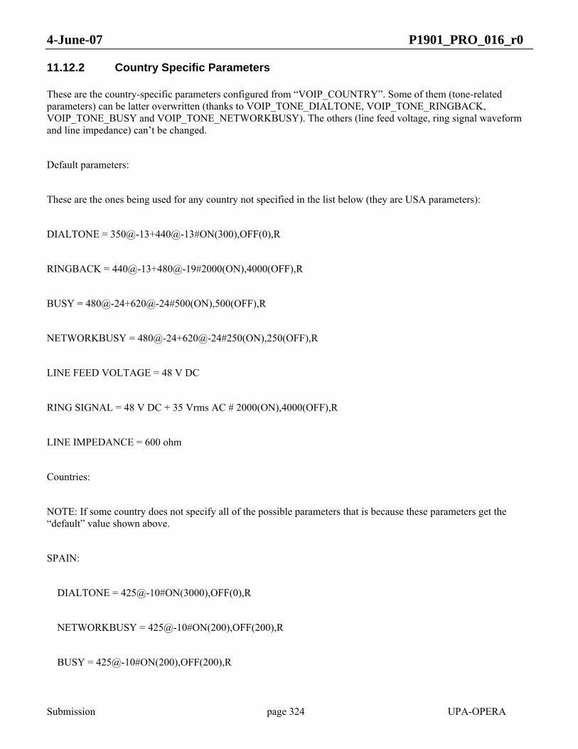
4-June-07 P1901_PRO_016_r0
Submission page 324 UPA-OPERA
11.12.2 Country Specific Parameters
These are the country-specific parameters configured from “VOIP_COUNTRY”. Some of them (tone-related parameters) can be latter overwritten (thanks to VOIP_TONE_DIALTONE, VOIP_TONE_RINGBACK, VOIP_TONE_BUSY and VOIP_TONE_NETWORKBUSY). The others (line feed voltage, ring signal waveform and line impedance) can’t be changed.
Default parameters:
These are the ones being used for any country not specified in the list below (they are USA parameters):
DIALTONE = 350@-13+440@-13#ON(300),OFF(0),R
RINGBACK = 440@-13+480@-19#2000(ON),4000(OFF),R
BUSY = 480@-24+620@-24#500(ON),500(OFF),R
NETWORKBUSY = 480@-24+620@-24#250(ON),250(OFF),R
LINE FEED VOLTAGE = 48 V DC
RING SIGNAL = 48 V DC + 35 Vrms AC # 2000(ON),4000(OFF),R
LINE IMPEDANCE = 600 ohm
Countries:
NOTE: If some country does not specify all of the possible parameters that is because these parameters get the “default” value shown above.
SPAIN:
DIALTONE = 425@-10#ON(3000),OFF(0),R
NETWORKBUSY = 425@-10#ON(200),OFF(200),R
BUSY = 425@-10#ON(200),OFF(200),R

4-June-07 P1901_PRO_016_r0
Submission page 325 UPA-OPERA
RINGBACK = 425@-10#ON(1500),OFF(3000),R
PORTUGAL:
DIALTONE = 425@-10#ON(3000),OFF(0),R
NETWORKBUSY = 425@-10#ON(200),OFF(200),R
BUSY = 425@-10#ON(200),OFF(200),R
RINGBACK = 425@-10#ON(1000),OFF(5000),R
RING SIGNAL = 48 V DC + 35 Vrms AC # 1000(ON),5000(OFF),R
UK:
DIALTONE = 350@-18+440@-18#ON(3000),OFF(0),R
NETWORKBUSY = 400@-14#ON(400),OFF(400),R
BUSY = 400@-14#ON(400),OFF(400),R
RINGBACK = 400@-15+450@-15#ON(400),OFF(200),ON(400),OFF(2000),R
JAPAN:
DIALTONE = 400@-15#ON(3000),OFF(0),R
NETWORKBUSY = 400@-5#ON(500),OFF(500),R
BUSY = 400@-5#ON(500),OFF(500),R
RINGBACK = 400@-10#ON(1000),OFF(2000),R
FRANCE:

4-June-07 P1901_PRO_016_r0
Submission page 326 UPA-OPERA
DIALTONE = 440@-13#ON(3000),OFF(0),R
NETWORKBUSY = 440@-13#ON(500),OFF(500),R
BUSY = 440@-13#ON(500),OFF(500),R
RINGBACK = 440@-13#ON(1500),OFF(3500),R
SINGAPORE:
DIALTONE = 425@-15#ON(3000),OFF(0),R
NETWORKBUSY = 425@-10#ON(750),OFF(750),R
BUSY = 425@-10#ON(750),OFF(750),R
RINGBACK = 425@-10#ON(400),OFF(200),R
RUSSIA:
DIALTONE = 425@-10#ON(400),OFF(400),R
RINGBACK = 425@-10#ON(800),OFF(3200),R
AUSTRALIA:
DIALTONE = 425@-10#ON(3000),OFF(0),R
NETWORKBUSY = 425@-10#ON(200),OFF(200),R
BUSY = 425@-10#ON(400),OFF(400),R
RINGBACK = 425@-10#ON(400),OFF(200),ON(400),OFF(2000),R
LINE IMPEDANCE = 220 ohm + 820 ohm || 120 nF

4-June-07 P1901_PRO_016_r0
Submission page 327 UPA-OPERA
11.12.3 Tone pattern configuration
The different available tones can be configured using the following ring cadence pattern: freq1@pot1+freq2@pot2#ON(time),OFF(time),IDLE(time),R. Only the following frequencies (in Hz) are possible: 350, 400, 425, 440, 480, 572, 620, 682, 697, 770, 852, 941, 1209, 1336, 1400, 1477, 1633, 2060, 2130, 2450, 2750 and 2600. An example will help to explain this string:
950@-25+420@-10#ON(330),OFF(30),IDLE(1000),R:
This will create the following tone:
• The tone will be the addition of two frequencies: 950Hz with a power of –25dBm plus 420Hz with a power of –10dBm
• It will be ON during 330 msecs.
• Then it will be OFF during 30 msecs.
• And then it will be IDLE for 1000 msecs. This IDLE number it is not mandatory in the string.
• R means that the sequence ON, OFF, IDLE will be repeated continuously.
To configure a continuous tone of 1400Hz and –10dBm, the following string should be used:
• 1400@-10#ON(3000),OFF(0),R
Therefore, the mandatory symbols are:
• @ to separate frequency and power.
• # to separate the tone frequency and power from the sound cadence.
• , to separate the ON(xx), OFF(xx) and IDLE(xx) parameters.
Besides, the tone may be an addition of two different frequencies and powers using the + symbol.
11.13 VLAN NETWORK
• VLAN_ENABLE = [yes|no]
o Parameter: ‘yes’ (to enable VLAN use) or ‘no’ (to disable VLAN use)
o SNMP: no
o Mandatory: yes

4-June-07 P1901_PRO_016_r0
Submission page 328 UPA-OPERA
This autoconfiguration parameter enables or disables the use of VLAN. Normally this parameter is not needed because the modem itself discovers the use of VLAN, but it is necessary in case of booting from local settings.
• VLAN_MNMT_TAG = [2-4093] | %<PARAMETRIC VALUE>
o Parameter: Number from 2 to 4093) or ‘%Parameter_name’ (parametric value preceded by a %)
o SNMP: no
o Mandatory: yes
This parameter indicates the management VLAN_ID (VID) of high-level management protocols (Telnet, Ping, …). Often a parametric value is used, and so the appropriate parameter will be taken from the translation table (for example, writing ‘$VLAN_DATA_2’).
• VLAN_MNMT_PRIO = [0-7]
o Parameter: Number from 0 to 7.
o SNMP: no
o Mandatory: yes
This autoconfiguration parameter sets the VLAN priority for the high-level management (Telnet, Ping, …) packets.
• VLAN_DATA_TAG = [2-4093] | %<PARAMETRIC VALUE>
o Parameter: Number from 2 to 4093 or ‘%Parameter_name’ (parametric value preceded by a %).
o SNMP: no
o Mandatory: yes
This parameter is used at the EU nodes. It configures the VLAN_ID (VID) for the data packets (packets coming from the external interfaces). The value set can be a value (from 2 to 4093) or a parametric value. In this last case, the adequate value will be taken from the translation table.
• VLAN_DATA_PRIO = [0-6]
o Parameter: Number from 0 to 6.
o SNMP: no
o Mandatory: yes
This parameter is used at the EU nodes. It configures the VLAN priority for the data packets (packets coming from the external interfaces).

4-June-07 P1901_PRO_016_r0
Submission page 329 UPA-OPERA
• VLAN_VOIP_TAG = [2-4093] | %<PARAMETRIC VALUE>
o Parameter: Number from 2 to 4093 or ‘%Parameter_name‘ (parametric value preceded by a %)
o SNMP: no
o Mandatory: no
This parameter configures the VLAN_ID (VID) for the VoIP packets (packets coming from the external interfaces). The value set can be a value (from 2 to 4093) or a parametric value. In this last case, the adequate value will be taken from the translation table.
• VLAN_VOIP_PRIO = [0-7]
o Parameter: Number from 0 to 7
o SNMP: no
o Mandatory: no
This autoconfiguration parameter sets the VLAN priority for the VoIP packets.
• VLAN_VSIG_PRIO = [0-7]
o Parameter: Number from 0 to 7
o SNMP: no
o Mandatory: no
It configures the VLAN priority for the VoIP signalling packets.
• VLAN_TRUNK.i = [2-4093]
o Parameter: Number from 2 to 4093)
o SNMP: no
o Mandatory: yes
This parameter is usable at LV and MV nodes. It configures a list of VLAN trunks different from the ones inside the translation table that must be allowed in the node interfaces. It is necessary to configure these trunks for private VLANs between EUs in all intermediary equipment.
• VLAN_RETAG_EXTA_SRC = [0 | 2-4095]
o Parameter: ‘0’ (in order to disable retagging in interface) number from 2 to 4095.
o SNMP: no

4-June-07 P1901_PRO_016_r0
Submission page 330 UPA-OPERA
o Mandatory: yes
Autoconfiguration parameter used for VLAN retagging: External (Ethernet) interface A (EXTA) source tag. With 0, the retagging is disabled in EXTA interface.
• VLAN_RETAG_EXTA_DST = [0 | 2-4095]
o Parameter: ‘0’ (in order to disable retagging in interface) or number from 2 to 4095
o SNMP: no
o Mandatory: yes
Autoconfiguration parameter used for the VLAN retagging: External (Ethernet) interface A (EXTA) destination tag. With 0, the retagging is disabled in EXTA interface.
• VLAN_RETAG_EXTB_SRC = [0 | 2-4095]
o Parameter: ‘0’ (in order to disable retagging in interface) or number from 2 to 4095
o SNMP: no
o Mandatory: yes
Autoconfiguration parameter used for the VLAN retagging: External (Ethernet) interface B (EXTB) source tag. With 0, the retagging is disabled in EXTB interface.
• VLAN_RETAG_EXTB_DST = [0 | 2-4095]
o Parameter: ‘0’ (in order to disable retagging in interface) or number from 2 to 4095
o SNMP: no
o Mandatory: yes
Autoconfiguration parameter used for the VLAN retagging: External (Ethernet) interface B (EXTB) destination tag. With 0, the retagging is disabled in EXTB interface.
11.14 OVLAN PARAMETERS
The OVLAN parameters are used to configure the basic OVLAN configuration, which avoids the visibility between different customers in the access network. They are similar to the VLAN parameters specified above.
• OVLAN_ENABLE = [yes|no]
o Parameter: ‘yes’ (to enable OVLAN use) or ‘no’ (to disable OVLAN use)

4-June-07 P1901_PRO_016_r0
Submission page 331 UPA-OPERA
o SNMP: none
o Mandatory: yes
This autoconfiguration parameter enables or disables the use of OVLAN filtering.
• OVLAN_DATA_TAG = [2-4094] | %ROOTPATH_OVLAN
o Parameter: Number from 2 to 4093 or ‘%ROOTPATH_OVLAN’ (use the OVLAN Rootpath value)
o SNMP: none
o Mandatory: yes
This parameters specifies of the OVLAN ID assigned to the packets coming from the external interface. It should be the same as in the translation table to perform the basic OVLAN operation in all equipment except the one connected to the backbone, which will have the ALL_VLAN tag (4095).
• OVLAN_TRUNK.i = [2-4094]
o Parameter: Number from 2 to 4094
o SNMP: none
o Mandatory: yes
This parameter is used in LV and MV nodes, and it configures a list of OVLAN trunks different from the one inside the translation table that must be allowed in the node interfaces. It is necessary to configure these trunks for private OVLANs between EUs in all intermediary equipment.
11.15 CUSTOM VLAN/OVLAN PARAMETERS
• USE_CUSTOM_VLAN_OVLAN = [yes/no]
o Parameter: ‘yes’ (to enable the custom VLAN/OVLAN use) or ‘no’ (to disable the custom VLAN/OVLAN use)
o SNMP: none
o Mandatory: no
This parameter enables other VLAN/OVLAN parameters. If set to ‘yes’, it will configure the parameters that are set in the auto-configuration file. The connection will be lost if the new parameters are not properly configured in the auto-configuration file. It is necessary to specify several parameters with care or no connection will be possible between the modems.

4-June-07 P1901_PRO_016_r0
Submission page 332 UPA-OPERA
As a general rule, this configuration overrides the basic VLAN/OVLAN configuration. In order to decrease the risk of loosing connection, the VLAN/OVLAN filtering follows these rules:
• When the list is allowed, the tags specified here are added to the existing ones. This solution simplifies the configuration and decreases the risk of miss-configuration.
• When the list is forbidden, the lists are reset before inserting the tags specified here, due to the same reasons.
The VLAN/OVLAN custom configuration must be complemented with the profile parameters referred to the VLAN/OVLAN, to configure interfaces different from EXTA, EXTB, ROOT and OTHERS.
11.15.1 Custom VLAN Parameters
• VLAN_TAGGED_ONLY_IFACE_ROOT = [yes/no]
o Parameter: ‘yes’ (to enable tag only in interface root) or ‘no’ (to disable tag only in interface root)
o SNMP: none
o Mandatory: no
If this parameter is set to ‘yes’, the modem will drop packets without a VLAN tag entering the root interface (IFACE_ROOT).
• VLAN_TAGGED_ONLY_IFACE_EXTA = [yes/no]
o Parameter: ‘yes’ (to enable tag only in Ethernet A) or ‘no’ (to disable tag only in Ethernet A)
o SNMP: none
o Mandatory: no
If this parameter is set, the modem will drop packets without a VLAN tag entering external (Ethernet) interface A.
• VLAN_TAGGED_ONLY_IFACE_EXTB = [yes/no]
o Parameter: ‘yes’ (to enable tag only in Ethernet B) or ‘no’ (to disable tag only in Ethernet B)
o SNMP: none
o Mandatory: no
It this parameter is set, the modem will drop packets without a VLAN tag entering external (Ethernet) interface B.
• VLAN_TAGGED_ONLY_IFACE_PL_X= [yes/no]
Being X = 0 to 127 (BPL port)

4-June-07 P1901_PRO_016_r0
Submission page 333 UPA-OPERA
o Parameter: ‘yes’ (to enable tag only in BPL port X) or ‘no’ (to disable tag only in BPL port X)
o SNMP: none
o Mandatory: no
If this parameter is set, the modem will drop packets without a VLAN tag entering BPL interfaces (PL_X).
• VLAN_OUTFORMAT_TAG_IFACE_ROOT = [yes/no]
o Parameter: ‘yes’ (to tag output in root interface) or ‘no’ (to disable tag output in root interface)
o SNMP: none
o Mandatory: no
It this parameter is set, the modem will introduce a VLAN tag when sending packets to the root interface (IFACE_ROOT).
• VLAN_OUTFORMAT_TAG_IFACE_EXTA = [yes/no]
o Parameter: ‘yes’ (to tag output in Ethernet A) or ‘no’ (to disable tag output in Ethernet A)
o SNMP: none
o Mandatory: no
It this parameter is set, the modem will introduce a VLAN tag when sending packets to the external (Ethernet) interface A.
• VLAN_OUTFORMAT_TAG_IFACE_EXTB = [yes/no]
o Parameter: ‘yes’ (to tag output in Ethernet B) or ‘no’ (to disable tag output in Ethernet B)
o SNMP: none
o Mandatory: no
It this parameter is set, the modem will introduce a VLAN tag when sending packets to external (Ethernet) interface B.
• VLAN_OUTFORMAT_TAG_IFACE_PL_X = [yes/no]
Being X = 0 to 127 (BPL port)
o Parameter: ‘yes’ (to tag output in BPL port X) or ‘no’ (to disable tag output in BPL port X)
o SNMP: none

4-June-07 P1901_PRO_016_r0
Submission page 334 UPA-OPERA
o Mandatory: no
It this parameter is set, the modem will introduce a VLAN tag when sending packets to BPL port (PL_X).
• VLAN_PVID_PL_X = [2-4095]
Being X = 0 to 127 (BPL port)
o Parameter: Number from 2 to 4095
o SNMP: none
o Mandatory: no
This autoconfiguration parameter specifies the 802.1Q VLAN tag for tagging untagged packets from the BPL port (PL_X).
• VLAN_PVID_EXTA = [2-4095]
o Parameter: Number from 2 to 4095
o SNMP: none
o Mandatory: no
This autoconfiguration parameter specifies the 802.1Q VLAN tag for tagging untagged packets from the external interface A (EXTA).
• VLAN_PVID_EXTB = [2-4095]
o Parameter: Number from 2 to 4095
o SNMP: none
o Mandatory: no
This autoconfiguration parameter specifies the 802.1Q VLAN tag for tagging untagged packets from the external interface B (EXTB).
• VLAN_PVID_FW = [2-4095]
o Parameter: Number from 2 to 4095
o SNMP: none
o Mandatory: no
This autoconfiguration parameter specifies the 802.1Q VLAN tag for tagging untagged packets from the firmware interface (FW).

4-June-07 P1901_PRO_016_r0
Submission page 335 UPA-OPERA
• VLAN_DEFAULT_PRIO_PL_X = [0-7]
Being X = 0 to 127 (BPL port)
o Parameter: Number from 0 to 7
o SNMP: none
o Mandatory: no
This parameter configures the 802.1p priority for tagging untagged packets from the BPL interface (PL_X).
• VLAN_DEFAULT_PRIO_EXTA = [0-7]
o Parameter: Number from 0 to 7
o SNMP: none
This parameter configures the 802.1p priority for tagging untagged packets from external (Ethernet) interface A (EXTA).
• VLAN_DEFAULT_PRIO_EXTB = [0-7]
o Parameter: Number from 0 to 7
o SNMP: none
o Mandatory: no
This parameter configures the 802.1p priority for tagging untagged packets from external (Ethernet) interface B (EXTB).
• VLAN_DEFAULT_PRIO_FW = [0-7]
o Parameter: Number from 0 to 7
o SNMP: none
o Mandatory: no
This parameter configures the 802.1p priority for tagging untagged packets from firmware interface (FW).
• VLAN_IS_ALLOWED_IFACE_ROOT = [yes/no]
o Parameter: ‘yes’ (to set list as allowed) or ‘no’ (to set list as forbidden)
o SNMP: none
o Mandatory: no
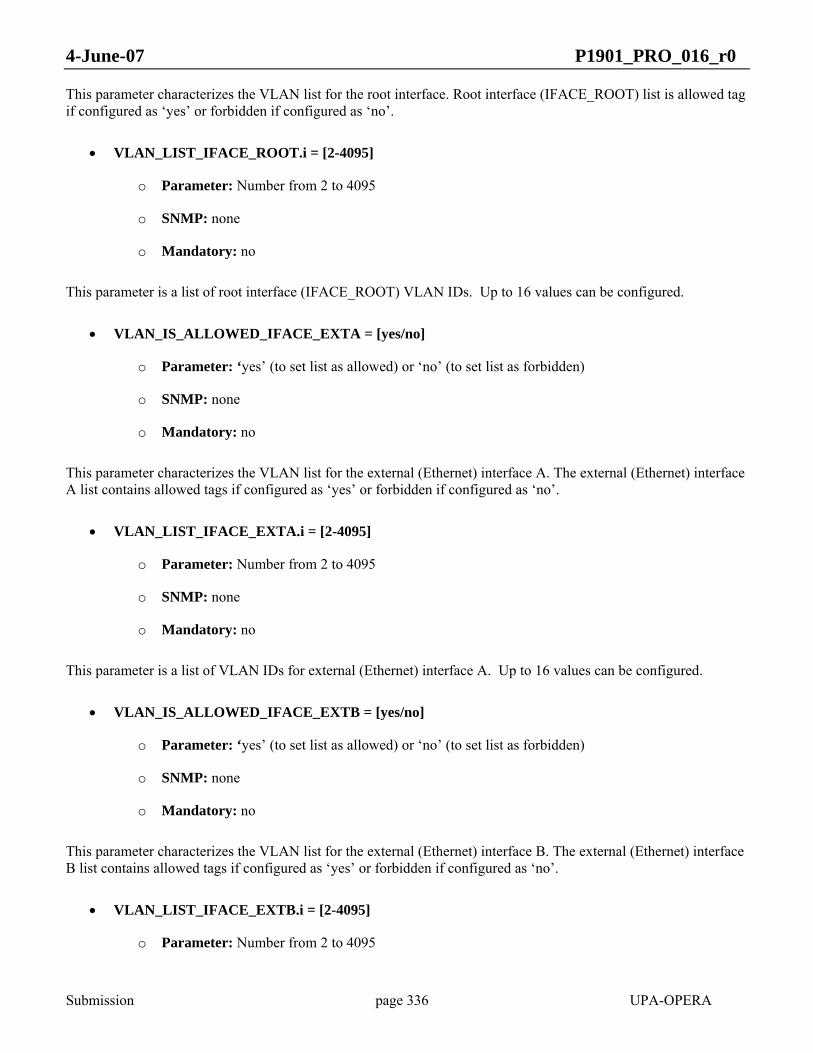
4-June-07 P1901_PRO_016_r0
Submission page 336 UPA-OPERA
This parameter characterizes the VLAN list for the root interface. Root interface (IFACE_ROOT) list is allowed tag if configured as ‘yes’ or forbidden if configured as ‘no’.
• VLAN_LIST_IFACE_ROOT.i = [2-4095]
o Parameter: Number from 2 to 4095
o SNMP: none
o Mandatory: no
This parameter is a list of root interface (IFACE_ROOT) VLAN IDs. Up to 16 values can be configured.
• VLAN_IS_ALLOWED_IFACE_EXTA = [yes/no]
o Parameter: ‘yes’ (to set list as allowed) or ‘no’ (to set list as forbidden)
o SNMP: none
o Mandatory: no
This parameter characterizes the VLAN list for the external (Ethernet) interface A. The external (Ethernet) interface A list contains allowed tags if configured as ‘yes’ or forbidden if configured as ‘no’.
• VLAN_LIST_IFACE_EXTA.i = [2-4095]
o Parameter: Number from 2 to 4095
o SNMP: none
o Mandatory: no
This parameter is a list of VLAN IDs for external (Ethernet) interface A. Up to 16 values can be configured.
• VLAN_IS_ALLOWED_IFACE_EXTB = [yes/no]
o Parameter: ‘yes’ (to set list as allowed) or ‘no’ (to set list as forbidden)
o SNMP: none
o Mandatory: no
This parameter characterizes the VLAN list for the external (Ethernet) interface B. The external (Ethernet) interface B list contains allowed tags if configured as ‘yes’ or forbidden if configured as ‘no’.
• VLAN_LIST_IFACE_EXTB.i = [2-4095]
o Parameter: Number from 2 to 4095
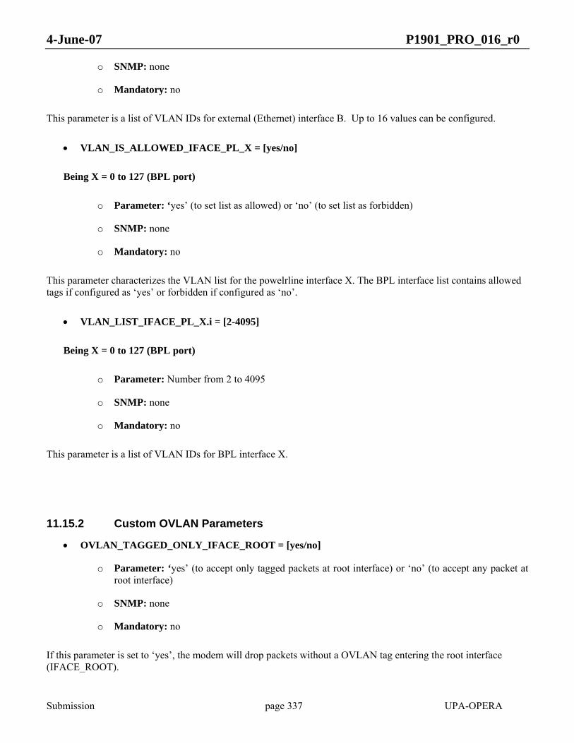
4-June-07 P1901_PRO_016_r0
Submission page 337 UPA-OPERA
o SNMP: none
o Mandatory: no
This parameter is a list of VLAN IDs for external (Ethernet) interface B. Up to 16 values can be configured.
• VLAN_IS_ALLOWED_IFACE_PL_X = [yes/no]
Being X = 0 to 127 (BPL port)
o Parameter: ‘yes’ (to set list as allowed) or ‘no’ (to set list as forbidden)
o SNMP: none
o Mandatory: no
This parameter characterizes the VLAN list for the powelrline interface X. The BPL interface list contains allowed tags if configured as ‘yes’ or forbidden if configured as ‘no’.
• VLAN_LIST_IFACE_PL_X.i = [2-4095]
Being X = 0 to 127 (BPL port)
o Parameter: Number from 2 to 4095
o SNMP: none
o Mandatory: no
This parameter is a list of VLAN IDs for BPL interface X.
11.15.2 Custom OVLAN Parameters
• OVLAN_TAGGED_ONLY_IFACE_ROOT = [yes/no]
o Parameter: ‘yes’ (to accept only tagged packets at root interface) or ‘no’ (to accept any packet at root interface)
o SNMP: none
o Mandatory: no
If this parameter is set to ‘yes’, the modem will drop packets without a OVLAN tag entering the root interface (IFACE_ROOT).

4-June-07 P1901_PRO_016_r0
Submission page 338 UPA-OPERA
• OVLAN_TAGGED_ONLY_IFACE_PL_X = [yes/no]
Being X = 0 to 127 (BPL port)
o Parameter: ‘yes’ (to accept only tagged packets at other interfaces) or ‘no’ (to accept any packet at other interfaces)
o SNMP: none
o Mandatory: no
If this parameter is set to ‘yes’, the modem will drop packets without a OVLAN tag entering BPL ports (PL_X).
• OVLAN_OUTFORMAT_TAG_IFACE_ROOT = [yes/no]
o Parameter: ‘yes’ (to introduce a tag in output packets at root interface) or ‘no’ (to not introduce a tag in output packets at root interface)
o SNMP: none
o Mandatory: no
If this parameter is set, the modem will introduce a OVLAN tag when sending packets to the root interface (IFACE_ROOT).
• OVLAN_OUTFORMAT_TAG_IFACE_PL_X = [yes/no]
Being X = 0 to 127 (BPL port)
o Parameter: ‘yes’ (to introduce a tag in output packets at BPL ports) or ‘no’ (to not introduce a tag in output packets at BPL ports)
o SNMP: none
o Mandatory: no
If this parameter is set, the modem will introduce a OVLAN tag when sending packets to BPL ports (PL_X).
• OVLAN_POVID_PL_X = [2-4095]
Being X = 0 to 127 (BPL port)
o Parameter: Number from 2 to 4095
o SNMP: none
o Mandatory: no

4-June-07 P1901_PRO_016_r0
Submission page 339 UPA-OPERA
This autoconfiguration parameter specifies the OVLAN tag for tagging untagged packets from the BPL port X (PL_X).
• OVLAN_POVID_EXTA = [2-4095]
o Parameter: Number from 2 to 4095
o SNMP: none
o Mandatory: no
This autoconfiguration parameter specifies the OVLAN tag for tagging untagged packets from the external interface A (EXTA).
• OVLAN_POVID_EXTB = [2-4095]
o Parameter: Number from 2 to 4095
o SNMP: none
o Mandatory: no
This autoconfiguration parameter specifies the OVLAN tag for tagging untagged packets from the external interface B (EXTB).
• OVLAN_POVID_FW = [2-4095]
o Parameter: Number from 2 to 4095
o SNMP: none
o Mandatory: no
This autoconfiguration parameter specifies the OVLAN tag for tagging untagged packets from the firmware interface (FW).
• OVLAN_IS_ALLOWED_IFACE_ROOT = [yes/no]
o Parameter: ‘yes’ (to set the root interface list as allowed) or ‘no’ (to set the root interface list as forbidden)
o SNMP: none
o Mandatory: no
This parameter characterizes the OVLAN list for the root interface. Root interface (IFACE_ROOT) list is allowed tag if configured as ‘yes’ or forbidden if configured as ‘no’.
• OVLAN_LIST_IFACE_ROOT.i = [2-4095]

4-June-07 P1901_PRO_016_r0
Submission page 340 UPA-OPERA
o Parameter: Number from 2 to 4095
o SNMP: none
o Mandatory: no
This parameter is a list of root interface (IFACE_ROOT) OVLAN tags.
• OVLAN_IS_ALLOWED_IFACE_EXTA = [yes/no]
o Parameter: ‘yes’ (to set the Ethernet A interface list as allowed) or ‘no’ (to set the Ethernet A interface list as forbidden)
o SNMP: none
o Mandatory: no
This parameter characterizes the OVLAN list for the external (Ethernet) interface A. The external (Ethernet) interface A list contains allowed tags if configured as ‘yes’ or forbidden if configured as ‘no’.
• OVLAN_LIST_IFACE_EXTA.i = [2-4095]
o Parameter: Number from 2 to 4095
o SNMP: none
o Mandatory: no
This parameter is a list of OVLAN tags for external (Ethernet) interface A.
• OVLAN_IS_ALLOWED_IFACE_EXTB = [yes/no]
o Parameter: ‘yes’ (to set the Ethernet B interface list as allowed) or ‘no’ (to set the Ethernet B interface list as forbidden)
o SNMP: none
o Mandatory: no
This parameter characterizes the OVLAN list for the external (Ethernet) interface B,. The external (Ethernet) interface B list contains allowed tags if configured as ‘yes’ or forbidden if configured as ‘no’.
• OVLAN_LIST_IFACE_EXTB.i = [2-4095]
o Parameter: Number from 2 to 4095
o SNMP: none
o Mandatory: no
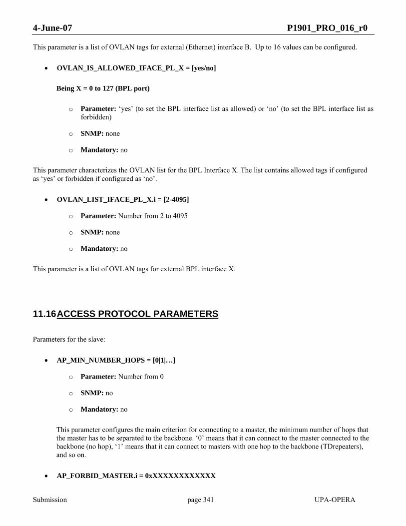
4-June-07 P1901_PRO_016_r0
Submission page 341 UPA-OPERA
This parameter is a list of OVLAN tags for external (Ethernet) interface B. Up to 16 values can be configured.
• OVLAN_IS_ALLOWED_IFACE_PL_X = [yes/no]
Being X = 0 to 127 (BPL port)
o Parameter: ‘yes’ (to set the BPL interface list as allowed) or ‘no’ (to set the BPL interface list as forbidden)
o SNMP: none
o Mandatory: no
This parameter characterizes the OVLAN list for the BPL Interface X. The list contains allowed tags if configured as ‘yes’ or forbidden if configured as ‘no’.
• OVLAN_LIST_IFACE_PL_X.i = [2-4095]
o Parameter: Number from 2 to 4095
o SNMP: none
o Mandatory: no
This parameter is a list of OVLAN tags for external BPL interface X.
11.16 ACCESS PROTOCOL PARAMETERS
Parameters for the slave:
• AP_MIN_NUMBER_HOPS = [0|1|…]
o Parameter: Number from 0
o SNMP: no
o Mandatory: no
This parameter configures the main criterion for connecting to a master, the minimum number of hops that the master has to be separated to the backbone. ‘0’ means that it can connect to the master connected to the backbone (no hop), ‘1’ means that it can connect to masters with one hop to the backbone (TDrepeaters), and so on.
• AP_FORBID_MASTER.i = 0xXXXXXXXXXXXX

4-June-07 P1901_PRO_016_r0
Submission page 342 UPA-OPERA
o Parameter: ‘0xXXXXXXXXXXXX’ (MAC address of forbidden master)
o SNMP: no
o Mandatory: yes
This parameter is a list of the MAC addressees of the masters this equipment has to avoid. The equipment will not connect to a master on this list, even if there are no other masters available.
• AP_PREFER_MASTER = 0xXXXXXXXXXXXX
o Parameter: ‘0xXXXXXXXXXXXX’ (MAC address of preferred master)
o SNMP: no
o Mandatory: yes
This parameter specifies a MAC address of a master that is preferred by the equipment. If the node can detect the master with this MAC address and it is not restricted (it is not forbidden and the number of hops is the adequate), it will try to connect to it regardless of any other parameter. If fails to connect to this prefer master, it will use the usual algorithm to decide to which master connect.
• AP_FIX_MASTER = ‘0xXXXXXXXXXXXX’
o Parameter: 0xXXXXXXXXXXXX (MAC address of fixed master)
o SNMP: no
o Mandatory: yes
This parameter specifies the only one master to which the node can connect. If this MAC address is not detected in the network, the node will not connect to any other one, so this parameter can be dangerous because if not properly configured can produce slaves unable to connect.
• AP_CHECK_BEST_MASTER_ENABLE = [yes|no]
o Parameter: ‘yes’ (to enable checking of best master periodically after connecting with one) or ‘no’ (to disable the checking of better masters after connecting to one).
o SNMP: no
o Mandatory: no
Once the node is connected to the network (after choosing and being accepted by a master) it is possible to repeat periodically the search of a better master. This parameter enables or disables the periodical check of the best master of the access protocol.
• AP_CHECK_BEST_MASTER_PERIOD = <time>
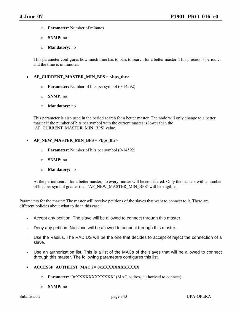
4-June-07 P1901_PRO_016_r0
Submission page 343 UPA-OPERA
o Parameter: Number of minutes
o SNMP: no
o Mandatory: no
This parameter configures how much time has to pass to search for a better master. This process is periodic, and the time is in minutes.
• AP_CURRENT_MASTER_MIN_BPS = <bps_thr>
o Parameter: Number of bits per symbol (0-14592)
o SNMP: no
o Mandatory: no
This parameter is also used in the period search for a better master. The node will only change to a better master if the number of bits per symbol with the current master is lower than the ‘AP_CURRENT_MASTER_MIN_BPS’ value.
• AP_NEW_MASTER_MIN_BPS = <bps_thr>
o Parameter: Number of bits per symbol (0-14592)
o SNMP: no
o Mandatory: no
At the period search for a better master, no every master will be considered. Only the masters with a number of bits per symbol greater than ‘AP_NEW_MASTER_MIN_BPS’ will be eligible.
Parameters for the master: The master will receive petitions of the slaves that want to connect to it. There are different policies about what to do in this case:
- Accept any petition. The slave will be allowed to connect through this master.
- Deny any petition. No slave will be allowed to connect through this master.
- Use the Radius. The RADIUS will be the one that decides to accept of reject the connection of a slave.
- Use an authorization list. This is a list of the MACs of the slaves that will be allowed to connect through this master. The following parameters configures this list.
• ACCESSP_AUTHLIST_MAC.i = 0xXXXXXXXXXXXX
o Parameter: ‘0xXXXXXXXXXXXX’ (MAC address authorized to connect)
o SNMP: no

4-June-07 P1901_PRO_016_r0
Submission page 344 UPA-OPERA
o Mandatory: no
This parameter is a list of the MAC address of the modems that will be allowed to connect through this master. The length of the list is 128 (i=1…128).
• ACCESSP_AUTHLIST_PROFILE.i = [1-16]
o Parameter: Number of the profile related to a MAC authorized)
o SNMP: no
o Mandatory: no
If a slave is accepted via the authorization list it will use the parameters of one profile. This autoconfiguration parameter indicates which profile will be associated with each slave. The length of the list is 128 (i=1…128).
• ACCESSP_AUTHLIST_FWTYPE.i = [MV|LV|EU]
o Parameter: ‘MV’ (medium voltage) or ‘LV’ (low voltage) or ‘EU’ (End User)
o SNMP: no
o Mandatory: no
If a slave is accepted via the authorization list it will have a firmware type This autoconfiguration parameter indicates which firmware type will be associated with each slave. The length of the list is 128 (i=1…128).
12 CONFIGURATION
12.1 MIB
12.1.1 SNMP Management
SNMP (Simple Network Management Protocol) refers to a group of specifications for the management of communication networks: the protocol, the data base definition and the modules. For more information, consult the SNMP standards RFC 1155 (Structure and Identification of Management Information for TCP/IP-based Internets), RFC 1157 (Simple Network Management Protocol), RFC 1213, Management Information Base).
Each resource to be managed in a device is represented by an object. The MIB is a structured collection of these objects. For SNMP, the MIB is a database structure, or a database definition. Each system in a network to be managed must maintain a MIB that reflects the status of the managed resources in that system.

4-June-07 P1901_PRO_016_r0
Submission page 345 UPA-OPERA
All managed objects in the SNMP environment are arranged in a hierarchical or tree structure. The leaf objects of the tree are the actual managed objects, each of which represents some resource, activity or related information that is to be managed.
SNMP and thus MIB support are optional in this specification.
12.1.2 MIB-II for IEEE P1901
The structure MIB-II is located under the node mgmt. This node contains the definition of the management information base approved by the IAB. MIB-II is an extension of the previously defined MIB-I. Under the node ‘mib-2’, IEEE P1901 nodes must support the following structures in RFC 1213:
• system(1): General information about the system:
o Description of the entity – hardware, operating system, etc.
o Level of OSI reference model to which the managed object pertains.
o Time since the last initialization of the system.
• interfaces(2): Information about the network interfaces of the managed entity, including information and statistics about the events in each. There is an “interfaces” table in which each row corresponds to a network interface. The information for a given interface:
o Physical address
o Type of interface
o Speed
o Status
o Number of transmitted and received octets
The implementation of the following nodes is optional.
• at(3): Translation of addresses IP – MAC.
• ip(4): Information about the configuration of the IP protocol over the device. Among others, the nodes under the ‘ip’ node contain information about:
o Number of packets discarded because of errors in the IP header, because of errors in the addresses, because of not finding a correct route, etc.
o Number of accepted packets.
o IP address of the interfaces and network mask of the network.
• icmp(5): Information about the Internet Control Message Protocol (ICMP).
4-June-07 P1901_PRO_016_r0
Submission page 346 UPA-OPERA
• tcp(6): General information about the TCP protocol working in the managed node.
• udp(7): General information about the UDP protocol.
• snmp(11): Information about the execution of the SNMP protocol in the entity.
All fundamentals for the MIB-II can be found in RFC 1213, and no further information will be shown in this document.
12.1.3 IEEE P1901 Private MIB
This section walks through the IEEE P1901 Private MIB.
Under the ‘.iso.org.dod.internet.private.enterprises’ node in the standard MIB, in position number 6798, the node assigned to DS2 (ds2 OBJECT IDENTIFIER ::= {enterprises 6798}) is allocated and in turn, under this node, the IEEE P1901 MIB branch has position 3 (IEEE P1901 OBJECT_IDENTIFIER ::= {ds2 3}) and contains all objects that are not supported in the standard MIB-II but can be remotely managed in an IEEE P1901 node.
Internally the IEEE P1901 (3) branch is composed of 8 sub-branches.
• plSystem: Generic information about the system.
• plBasic: Information about the general BPL configuration.
• plPhy: Information related to the physical layer indexed by node address.
• plMAC: Objects related to the Medium Access Control.
• plQoS: Objects related to Quality of Service.
• plOVLAN: Objects related to OVLAN.
• plStatistics: Statistics counters.
• plTraps: Trap information.
• plStp: STP information.
• plSecurity: Security configuration.

4-June-07 P1901_PRO_016_r0
Submission page 347 UPA-OPERA
enterprises (1)
ds2 (6798)
IEEE P1901 (3)
plSystem (1)
plBasic (2)
plPhy (3)
plMAC (4)
plQoS (5)
plOVLAN (6) plStatistics (7)
plTraps (8)
plStp (9)
plSecurity (10)
Figure 149 IEEE P1901 MIB tree
12.1.3.1 The IEEE P1901 MIB Description
This section shows the IEEE P1901 MIB and contains a brief description of every object inside each branch under the ‘IEEE P1901’ node. The MIB definition in ASN.1 format can be found in ANNEX A.
Note that not every OID can be accessed for get/set operations; read-only OIDs only accept ‘get’ operations, read-write OIDs accept both ‘get’ and ‘set’ operations, and nonaccessible OIDs accept neither of them (indicated in the table above). In addition, every OID with an enable/disable meaning accepts an integer ‘1’ for enabling and an integer ‘0’ for disabling.
plSystem
• plSystemTable
Almost every table in the IEEE P1901 MIB is indexed by the card number, so there will be a copy of this object in these tables; their explanation is equivalent to this one.
o plSysCard: Used as an index to get/set system characteristic data for a specific BPL card. This could be seen as useless because every BPL card has its own IP address, but it has been included to support future improvements in IEEE P1901 technology where a single node will have a single IP address, independent of the number of cards it will hold. But at present, this index is always a fixed ‘1’ value.
o plSysNodeType: Node type. An IEEE P1901 BPL card can act as a master, slave or repeater, and therefore this OID can hold the values of 0:Master, 1:Slave and 2:Repeater.
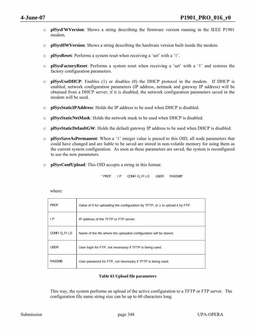
4-June-07 P1901_PRO_016_r0
Submission page 348 UPA-OPERA
o plSysFWVersion: Shows a string describing the firmware version running in the IEEE P1901 modem.
o plSysHWVersion: Shows a string describing the hardware version built inside the modem.
o plSysReset: Performs a system reset when receiving a ‘set’ with a ‘1’.
o plSysFactoryReset: Performs a system reset when receiving a ‘set’ with a ‘1’ and restores the factory configuration parameters.
o plSysUseDHCP: Enables (1) or disables (0) the DHCP protocol in the modem. If DHCP is enabled, network configuration parameters (IP address, netmask and gateway IP address) will be obtained from a DHCP server; if it is disabled, the network configuration parameters saved in the modem will be used.
o plSysStaticIPAddress: Holds the IP address to be used when DHCP is disabled.
o plSysStaticNetMask: Holds the network mask to be used when DHCP is disabled.
o plSysStaticDefaultGW: Holds the default gateway IP address to be used when DHCP is disabled.
o plSysSaveAsPermanent: When a ‘1’ integer value is passed to this OID, all node parameters that could have changed and are liable to be saved are stored in non-volatile memory for using them as the current system configuration. As soon as these parameters are saved, the system is reconfigured to use the new parameters.
o plSysConfUpload: This OID accepts a string in this format:
“PROT IP CONFIG_FILE USER PASSWD“
where:
PROT Value of 0 for uploading the configuration by TFTP, or 1 to upload it by FTP.
IP IP address of the TFTP or FTP server.
CONFIG_FILE Name of the file where the uploaded configuration will be stored.
USER User login for FTP, not necessary if TFTP is being used.
PASSWD User password for FTP, not necessary if TFTP is being used.
Table 63 Upload file parameters
This way, the system performs an upload of the active configuration to a TFTP or FTP server. The configuration file name string size can be up to 60 characters long.

4-June-07 P1901_PRO_016_r0
Submission page 349 UPA-OPERA
o plSysConfDownload: This OID accepts a string in this format:
“PROT IP CONFIG_FILE USER PASSWD“
where:
PROT Value of 0 for downloading the configuration file by TFTP, or 1 to download it by FTP.
IP IP address of the TFTP or FTP server.
CONFIG_FILE Name of the file to be downloaded.
USER User login for FTP, not necessary if TFTP is being used.
PASSWD User password for FTP, not necessary if TFTP is being used.
Table 64 Download configuration file parameters
This way, the system performs a download of a new configuration file from a FTP or TFTP server. The configuration file name string size can be up to 60 characters long.
o plSysUpgradeStatus: This OID is read-only and shows an integer number, which is a special code for showing the current status of the upgrade in progress. The codes for this OID are:
0 Last upgrade was performed correctly.
-1 No FLASH upgrade has been performed since the last boot.
-2 Last upgrade failed checking CRC.
-3 Last upgrade failed due to src was incorrect.
-4 Last upgrade failed due to destination (FLASH sector) was incorrect.
-5 Last upgrade failed due to file was for an incorrect HW product.
-6 Last upgrade failed due to file was for an incorrect HW Revision.
-7 Last upgrade failed due to file was for an incorrect ASIC.
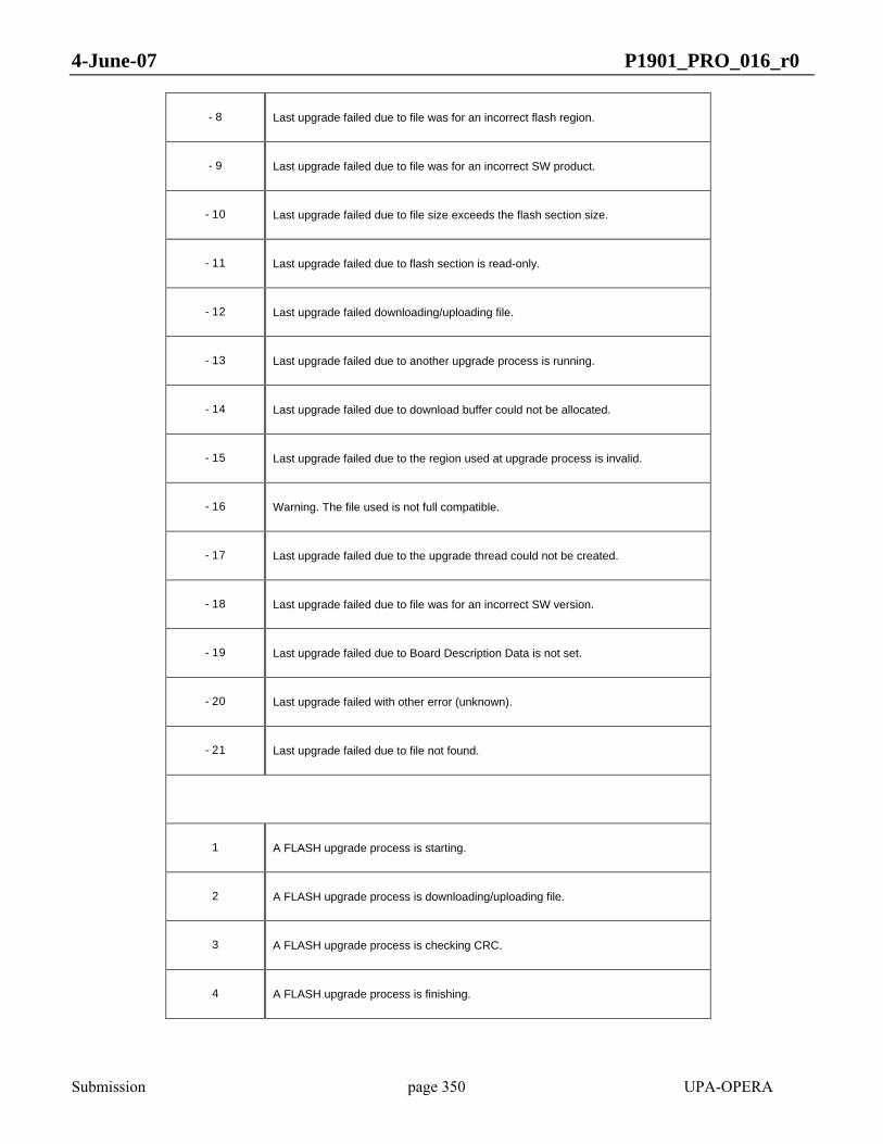
4-June-07 P1901_PRO_016_r0
Submission page 350 UPA-OPERA
-8 Last upgrade failed due to file was for an incorrect flash region.
-9 Last upgrade failed due to file was for an incorrect SW product.
-10 Last upgrade failed due to file size exceeds the flash section size.
-11 Last upgrade failed due to flash section is read-only.
-12 Last upgrade failed downloading/uploading file.
-13 Last upgrade failed due to another upgrade process is running.
-14 Last upgrade failed due to download buffer could not be allocated.
-15 Last upgrade failed due to the region used at upgrade process is invalid.
-16 Warning. The file used is not full compatible.
-17 Last upgrade failed due to the upgrade thread could not be created.
-18 Last upgrade failed due to file was for an incorrect SW version.
-19 Last upgrade failed due to Board Description Data is not set.
-20 Last upgrade failed with other error (unknown).
-21 Last upgrade failed due to file not found.
1 A FLASH upgrade process is starting.
2 A FLASH upgrade process is downloading/uploading file.
3 A FLASH upgrade process is checking CRC.
4 A FLASH upgrade process is finishing.

4-June-07 P1901_PRO_016_r0
Submission page 351 UPA-OPERA
99 A FLASH upgrade process is in unknown status.
Table 65 Upgrade status code list
o plSysUpdate: This OID accepts a string in this format:
“PROT IP CONFIG_FILE USER PASSWD“
where:
PROT Value of 0 for downloading the firmware by TFTP, or 1 to download it by FTP.
IP IP address of the TFTP or FTP server.
CONFIG_FILE Name of the file to be downloaded.
TYPE Type of file 1:FW imag, 2 Loader image, etc.
USER User login for FTP, not necessary if TFTP is being used.
PASSWD User password for FTP, not necessary if TFTP is being used.
Table 66 Update system parameters
This way, the system performs an update of the firmware, loader or whatever part of the code in a modem from a TFTP or FTP server. The configuration file name string size can be up to 60 characters long.
o plSysDNSAddress: Holds the DNS IP address.
o plSnmpROComunityName: Holds the community name string.
o plSnmpRWComunityName: Holds the community name string.
o plSnmpTrapDest: Holds the IP address to send the traps to.
plBasic
• plBasicTable

4-June-07 P1901_PRO_016_r0
Submission page 352 UPA-OPERA
o plBasicCard: Card index.
o plBasicMode: Physical mode used by the modem. These values can reach from 1 to M, depending on the range of frequency used.
o plBasicCentralFrequency: Mode central frequency value in KHz.
o plBasicBandwidth: Mode bandwidth in MHz.
o plBasicTXAGCEnable: Enables/disables transmission AGC. This AGC feature controls transmission gains automatically and dynamically.
o plBasicRXAGCEnable: Enables/disables reception AGC.
o plBasicTXAGCGain: Sets/gets the transmission gain, and it can accept two values, ‘0’ and ‘1’. These values have a ‘distance’ of 12 dB and act over the AFE amplifiers.
o plBasicRXAGCGain: Sets/gets the gain in reception, in a range of values from ‘0’ to ‘7’ in steps of 6 dB.
o plBasicTXPowerMaskLB: Sets/gets the system powermask in the low half band of frequencies in the whole bandwidth used by the IEEE P1901 node, from carrier numbers 1 to 768. The value is a 768-character long string, each character corresponding to a carrier, that is, the first character corresponds to carrier number 1 and so on. These characters have a special coding, and its meaning has to be split into two sub-codes, e.g.:
First 4 bits coded in steps of 6 dB for coarse attenuation.
Last 4 bits specially coded for fine attenuation.
0100 0110
The coding for the last 4 bits can be deduced from this graph:

4-June-07 P1901_PRO_016_r0
Submission page 353 UPA-OPERA
Figure 150 Power mask encoding graphic
o plBasicTXPowerMaskHB: Sets/gets the system powermask in the high half band frequencies of the whole bandwidth used by the IEEE P1901 node, from carrier numbers 769 to 1536. The explanation of the value of this OID is equivalent to the previous one.
o plBasicMasterMAC: Shows the MAC address of the current master of the node.
plPhy
• plPhyByMACTable
o plPhyByMACCard: Card index.
o plPhyByMACMAC: Physical (MAC) address that also serves as an index. This means that all of the following OIDs will refer to a single MAC address. These MAC addresses are those that have been learned by the MAC protocol or configured manually. Other tables could be also indexed by MAC, and all of them would mean that the value shown affects that MAC.
o plPhyByMACTXBPC: For all practical purposes, these are the tonemap associated to the indexed MAC in transmission. The value is a 768-character long string with numbers from 2 to 10, each number representing the number of bits per symbol of each carrier. Each byte contains two carriers (4 bits each).
Note: All BPC OIDs are the result of applying the Adaptive Bitloading ProtoCol, for which BPC is the acronym.

4-June-07 P1901_PRO_016_r0
Submission page 354 UPA-OPERA
o plPhyByMACTXBPCAggregated: Holds the aggregated BPC value in transmission, which is a value from 288 to 14592. Although the maximum number of bits per carrier is 10 and the number of carriers is 1536, the physical throughput requires making a subtraction of 0.5 bits for each BPC value, which is used by the FEC algorithm. Therefore, 1536 times 9.5 results in 14592.
o plPhyByMACTXPhySpeed: Physical speed in transmission in Mbits per second.
o plPhyByMACRXBPC: These are the BPCs associated to the indexed MAC in reception. The value is a 768-character long string with numbers ranging from 2 to 10, each number representing the number of bits per symbol for each carrier. Each byte contains two carriers (4 bits each).
o plPhyByMACRXBPCAggregated: Shows the aggregated BPC value in reception, which is a value from 288 to 14592. Although the maximum number of bits per carrier is 10 and the number of carriers is 1536, the physical throughput requires making a subtraction of 0.5 bits for each BPC value, which is used by the FEC algorithm. Therefore, 1536 times 9.5 results in 14592.
o plPhyByMACRXPhySpeed: Physical speed in reception in Mbits per second.
o plPhyByMACSNR: Shows the measured channel SNR. The value shown is a 768-character long string where each character is a number that shows the SNR value in units of 0.5 dB.
o plPhyByMACCFR: Shows the measured channel CFR. The value shown is a 768-character long string where each character is a number that shows the CFR value in units of 1 dB.
o plPhyByMACACK: Enables/disables the level 2 ACKs feature.
o plPhyByMACCipher: Enables/disables the cipher feature.
o plPhyByMACTxHURTO: Forces HURTO mode in transmission for a ‘set’ operation, or indicates if the modem is transmitting in HURTO mode to the indexed MAC for a ‘get’ operation.
o plPhyByMACRxHURTO: Forces HURTO mode in reception for a ‘set’ operation, or indicates if the modem is receiving in HURTO mode from the indexed MAC for a ‘get’ operation.
o plPhyByMACIsActive: Used to check if a node, whose MAC is the index, is active (1) or not (0).
o plPhyByMACRXTimeLastActivity: Indicates the number of seconds since the last time the indexed MAC showed BPL activity.
• plPhyRXSNRThresholdTable
o plPhyRXSNRThresholdCard: Card index.
o plPhyRXSNRThresholdIndex: The IEEE P1901 modems have 9 levels of SNR thresholds for changing the BPCs to be used when these levels are reached. This OID is an index with fixed values from 1 to 10 to refer to the BPCs to be used when a certain SNR value is reached. For instance, if data is requested (see the OID below) for the index 6, it will return the SNR value from which 6 BPCs will be used.
o plPhyRXSNRThreshold: SNR threshold value in units of 0.5 dB for a determinate threshold index in the above OID.
plMAC

4-June-07 P1901_PRO_016_r0
Submission page 355 UPA-OPERA
• plMACTable
o plMACCard: Card index.
o plMACAccessProtocol: Enables/disables the Access Protocol mode, which has been implemented to allow a node to automatically learn the MAC addresses of the nodes that are liable to connect with it.
o plMACNumConnectedNodes: Shows the number of nodes successfully connected, that is, with its link solved by the Port Solver Protocol.
o plMACNumSlaves: Shows the number of configured slaves if the nodeis a master.
• plMACConnectedNodesTable
o plMACConnectedNodesCard: Card index.
o plMACConnectedNodesIndex: This index will refer to a connected node, a number ranging from 0 to the value shown by plMACNumConnectedNodes (see above).
o plMACConnectedNodesMAC: MAC address of the indexed connected node.
• plMACSlavesTable
o plMACSlavesCard: Card index.
o plMACSlavesIndex: This index will refer to a slave node, a number ranging from 0 to the value shown by plMACNumSlaves (see above).
o plMACSlavesMAC: MAC address of the indexed slave node.
plQoS
• plQoSMasterGeneralMinOneWayLat
If the modem is a master, this OID shows the minimum latency configured in the modem in milliseconds.
• plQoSMasterGeneralBwMngrPolicy
This OID shows the policy to be followed by a master in assigning a certain bandwidth to its attached slaves. If a 0 is returned, the master is configured to assign bandwidth in a fair policy, while if a 1 is returned, the bandwidth is assigned in a priority-based policy.
• plQoSPriorityManagementTable
o plQoSPriorityManagementCard: Card index.
o plQoSPriorityManagementPrio: Priority value, from 1 to 8.

4-June-07 P1901_PRO_016_r0
Submission page 356 UPA-OPERA
o plQoSPriorityManagementLatency: Latency coding value for the priority. Allowed coding values are 0, 1, 2, 4 and 8
o plQoSPriorityManagementTimmingInterval: A fixed scheduling repeated each programmable Timming Interval is set, and the slaves will have a fixed amount of assigned time to transmit. This scheduling may be synchronized with the mains.
• plQoSPerUserTable
o plQoSPerUserCard: Card index.
o plQoSPerUserMAC: Physical MAC address of the user hanging from the master. Used as index.
o plQoSPerUserTXMaxXput: Shows the maximum throughput allowed in transmission for a user in kilobits per second.
o plQoSPerUserRXMaxXput: Shows the maximum throughput allowed in reception for a user in kilobits per second.
o plQoSPerUserPriorityAllowedUp: Shows the allowed priorities for transmission and reception in upstream for a user. The returned value is a number from 0 to 255, which is a number corresponding to the allowed priorities’ 8-bit mask coding, i.e., a value of 16 (0010000b) would mean that priority 5 is the only one allowed.
o plQoSPerUserPriorityAllowedDown: Shows the allowed priorities for transmission and reception in downstream for a user. The returned value is a number from 0 to 255, which is a number corresponding to the allowed priorities’ 8-bit mask coding, i.e., a value of 17 (0010001b) would mean that priorities 5 and 1 are the only ones allowed.
plOVLAN
This node has the same structure and OID that the dot1qVlan MIB branch.
plStatistics
• plStatisticsTable
o plStatisticsCard: Card index.
o plStatisticsBPLInputWords: Number of words received by the BPL physical interface.
o plStatisticsBPLInputPackets: Number of packets received by the BPL physical interface.
o plStatisticsBPLInputIncorrigible: Number of incorrigible packets received by the BPL physical interface.
o plStatisticsBPLInputFECBlocksTotal: Number of FEC blocks received by the BPL physical interface.
o plStatisticsBPLInputFECBlocksCorrected: Number of FEC blocks received and corrected by the BPL physical interface.
o plStatisticsBPLInputPktsReceived: Number of packets received by the BPL physical interface.
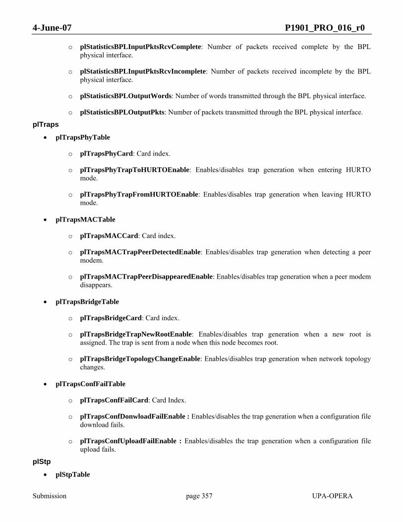
4-June-07 P1901_PRO_016_r0
Submission page 357 UPA-OPERA
o plStatisticsBPLInputPktsRcvComplete: Number of packets received complete by the BPL physical interface.
o plStatisticsBPLInputPktsRcvIncomplete: Number of packets received incomplete by the BPL physical interface.
o plStatisticsBPLOutputWords: Number of words transmitted through the BPL physical interface.
o plStatisticsBPLOutputPkts: Number of packets transmitted through the BPL physical interface.
plTraps
• plTrapsPhyTable
o plTrapsPhyCard: Card index.
o plTrapsPhyTrapToHURTOEnable: Enables/disables trap generation when entering HURTO mode.
o plTrapsPhyTrapFromHURTOEnable: Enables/disables trap generation when leaving HURTO mode.
• plTrapsMACTable
o plTrapsMACCard: Card index.
o plTrapsMACTrapPeerDetectedEnable: Enables/disables trap generation when detecting a peer modem.
o plTrapsMACTrapPeerDisappearedEnable: Enables/disables trap generation when a peer modem disappears.
• plTrapsBridgeTable
o plTrapsBridgeCard: Card index.
o plTrapsBridgeTrapNewRootEnable: Enables/disables trap generation when a new root is assigned. The trap is sent from a node when this node becomes root.
o plTrapsBridgeTopologyChangeEnable: Enables/disables trap generation when network topology changes.
• plTrapsConfFailTable
o plTrapsConfFailCard: Card Index.
o plTrapsConfDonwloadFailEnable : Enables/disables the trap generation when a configuration file download fails.
o plTrapsConfUploadFailEnable : Enables/disables the trap generation when a configuration file upload fails.
plStp
• plStpTable

4-June-07 P1901_PRO_016_r0
Submission page 358 UPA-OPERA
o plStpCard: Card index.
o plStpEnable: Enables/disables the Spanning Tree protocol.
o plStpProtocolVersion: Chooses either using STP (IEEE 802.1d) or RSTP (IEEE 802.1w). The RSTP version is compatible to STP on a per-port basis. Values: “STP”, RSTP”.
o plStpPtpExtA: Sets the point-to-point flag on EXTA. This port will be considered point-to-point, thus candidate for rapid transition to forwarding. Set by default when EXTA is connected to backplane.
o plStpPtpExtB: Sets the point-to-point flag on EXTB. This port will be considered point-to-point, thus candidate for rapid transition to forwarding. Set by default when EXTB is connected to backplane.
o plStpFrontier: Enables/disables the Spanning Tree Frontier . This feature drops all the STP messages on an EXT interface. Values: “NONE”, “EXTA”, EXTB”.
plSecurity o plSecurityConsoleSerial: Enables or disables the serial console access to the modem.
o plSecurityConsoleTelnet: Enables or disables the telnet console access to the modem.
o plSecurityConsoleAuthTable: Table containing the IP addresses from which telnet clients may access this
12.2 AUTO-CONFIGURATION AND PROVISIONING
12.2.1 Auto-configuration purpose
The purpose of the auto-configuration process is the complete automation of the deployment of the BPL network:
• Medium Voltage equipment
• Low Voltage Repeaters and Home Gateways
• CPEs
With the auto-configuration mechanism no prior pre-configuration of any modem is required.
12.2.2 Auto-configuration process overview
The objective of the auto-configuration process is the centralized management of a BPL network using configuration files stored in a centralized database that are transferred to each node when it boots. These files contain all of the information that a node needs to know to work as expected.
Below is a brief description of the process:

4-June-07 P1901_PRO_016_r0
Submission page 359 UPA-OPERA
1. Every node starts with the same default factory configuration: Access CPE.
2. Using PTTP (explained later in this document 12.2.5) the modem discovers if it is booting in a network with VLANs or not. If a network has been built using VLANs it is necessary to know the Management VLAN of that network segment for the DHCP request to reach the backbone. The information passed between modems during PTTP is called the translation table.
3. Using DHCP protocol, each node gets their IP configuration (IP address, netmask and gateway), the phone number (in the case of VoIP CPEs), the name of their corresponding auto-configuration file and the IP address of the TFTP server where the auto-configuration file is.
4. Using TFTP protocol, the nodes download the auto-configuration file and configure the node accordingly.
The four points mentioned above are the main ones, but there is another point to consider:
In order to achieve a secure network, BPL authentication is introduced. When a new slave is trying to access the BPL network and connecting to a master or a repeater, the master or repeater may perform a RADIUS request to authenticate the user. See section 12.2.9 for more information.
Below there is an example of the actions involved in the auto-configuration of a slave modem:
PLC
Master
DHCP Server
TFTP Server
Radius Server
Slave Slave
Searchlink Access
Protocol
Slave
Master
MAC Authentication
RadiusRequest RadiusReply
with Profile
Slave
Master
PSP NegotiationSTP
Access Grant
Master
Slave
Gets Translation Tablewith Mgmt VLAN
PTTP Request
PTTP Reply
Gets IP address + Name of Configuration
File
DHCP Request
DHCP Reply
Slave
DownloadsConfiguration File
Slave
TFTP Request
Master
Figure 151 Autoconfiguration of a slave modem
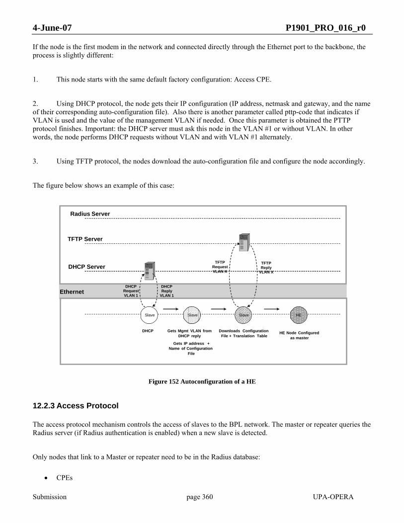
4-June-07 P1901_PRO_016_r0
Submission page 360 UPA-OPERA
If the node is the first modem in the network and connected directly through the Ethernet port to the backbone, the process is slightly different:
1. This node starts with the same default factory configuration: Access CPE.
2. Using DHCP protocol, the node gets their IP configuration (IP address, netmask and gateway, and the name of their corresponding auto-configuration file). Also there is another parameter called pttp-code that indicates if VLAN is used and the value of the management VLAN if needed. Once this parameter is obtained the PTTP protocol finishes. Important: the DHCP server must ask this node in the VLAN #1 or without VLAN. In other words, the node performs DHCP requests without VLAN and with VLAN #1 alternately.
3. Using TFTP protocol, the nodes download the auto-configuration file and configure the node accordingly.
The figure below shows an example of this case:
Slave
DHCP Server
TFTP Server
Radius Server
SlaveSlave
Gets Mgmt VLAN fromDHCP reply
Slave
Gets IP address + Name of Configuration
File
HE
Downloads ConfigurationFile + Translation Table
TFTP RequestVLAN X
TFTP Reply
VLAN X
HE Node Configured as master
DHCP
DHCP Request VLAN 1
DHCP Reply
VLAN 1Ethernet
Figure 152 Autoconfiguration of a HE
12.2.3 Access Protocol
The access protocol mechanism controls the access of slaves to the BPL network. The master or repeater queries the Radius server (if Radius authentication is enabled) when a new slave is detected.
Only nodes that link to a Master or repeater need to be in the Radius database:
• CPEs

4-June-07 P1901_PRO_016_r0
Submission page 361 UPA-OPERA
• TD Repeaters
The Radius server checks:
• The MAC address of the slave applying for authentication
• The MAC address of the master placing the request
The Radius server replies:
• Accept / Reject
• Profile number
The profile number relates to the QoS and VLAN settings for the given slave (Radius user).
If Access Protocol authentication is disabled, all slaves get access to the network with the default settings (profile 1).
A third type of authentication is possible: Authlist. In this mode, the autoconfiguration file of the master contains all the slaves that are allowed to connect and their associated profile.
12.2.4 Auto-configuration at Modem Boot
autoconfiguration parameters on booting. When any node boots, there may be a parameter stored in the non-volatile memory called GENERAL_USE_AUTOCONF. When this value is YES, the node boots in auto-configuration mode. When this value is NO, the node boots from local settings.
Inside the autoconfiguration boot mode there are two possibilities depending on whether or not PTTP is performed.
12.2.4.1 Autoconfiguration PTTP Boot
send PTTP requests. When this protocol ends, the modem has the minimum information to successfully connect to the backbone and execute DHCP and TFTP.
The node then performs a DHCP request to get an IP configuration, the phone number (if required) and the name of the auto-configuration file, as well as the TFTP server where the file is located. Then it downloads the file and configures the node accordingly.
12.2.4.2 Autoconfiguration no PTTP Boot
In this autoconfiguration boot modality, the modem has been already configured somehow (see section 12.2.5 for more information) to successfully execute DHCP and TFTP so it skips PTTP.
4-June-07 P1901_PRO_016_r0
Submission page 362 UPA-OPERA
This mode requires pre-configuration and it is only recommended in the first node of the BPL network, the node that connects to the backbone, because this node cannot get the information for booting from any other node. However, there is defined a DHCP extension to solve this issue without pre-configuration. See section 12.2.8.
12.2.4.3 Boot from local settings
When a node starts in local settings boot mode, it collects all of the configured parameters from the non-volatile memory and configures the node accordingly. There are some basic parameters that are always configured in this mode:
• GENERAL_TYPE: Node type – HE, CPE, or TDREPEATER.
• GENERAL_IP_USE_DHCP: Use DHCP – yes or no. If this parameter is set to no, the IP configuration parameters and the phone number are also configured from non-volatile memory.
All of the other parameters are only configured if they have been downloaded from a file first, and a GENERAL_USE_AUTOCONF = no line was in that auto-configuration file. This is equivalent to performing a Save as Permanent.
12.2.5 PTTP Protocol
The PTTP (Parametric Translation Table Protocol) is used to transfer the translation table (explained later in this document) between modems at booting. The PTTP uses the CCP
12.2.5.1 General description
The Parametric translation table protocol takes place every time a node boots. The aim of this protocol is to obtain from the nearest active node a table with the values of certain auto-configuration parameters. When the node downloads the auto-configuration file it uses the obtained values to translate all the parametric values contained in the file.
The translation table contains information about the different VLAN and OVLAN tags used in the network, as well as information about the QoS settings. If the network is not using VLAN tags, this information is also contained in the translation table. Due to this, it is necessary to perform the protocol before the DHCP request.
Once the translation table is obtained, the node is able to perform the DHCP request successfully and download and interpret the auto-configuration file, translating the parametric values contained on it.
12.2.5.2 Protocol description
The Translation Table protocol is client-server. Each node belonging to the network at boot time represents the client side. Each configured node in the network excluding End Users nodes performs the server side of the protocol.
The usual sequence of packet exchanging is described:

4-June-07 P1901_PRO_016_r0
Submission page 363 UPA-OPERA
1. The client starts sending a Read ReQuest (RRQ) packet through all active interfaces.
2. The closest server receives the RRQ packet and it sends the first block of the Translation Table to the client with a DATA packet with block number 1.
3. The client answers with an ACK packet of the block number 1.
4. The server sends the next block of DATA.
5. The client replies with another ACK
6. Steps 4 and 5 are repeated until the translation table is sent completely.
7. The server sends an empty DATA packet to finish the protocol.
8. The client replies with an ACK to this empty packet and closes the connection.
9. The server receives the last ACK and closes the connection.
The following figure shows this sequence:

4-June-07 P1901_PRO_016_r0
Submission page 364 UPA-OPERA
DST: DS2 MulticastSRC: MAC_x
Preforwarded toactive ports
ClientMAC_x
ServerMAC_y
PTTP.RRQ
PTTP.DATA(1)DST: MAC_xSRC: MAC_y
PTTP.ACK(1)DST: MAC_ySRC: MAC_x
PTTP.DATA(2)
PTTP.ACK(2)
Last block ACKreceived
Close connection
Close connection
Open connectionLearn source MAC
address
Open connectionLearn source MAC
address
Last data blockreceived (empty)
PTTP.DATA(N)Empty
PTTP.ACK(N)
Figure 153 Usual PTTP operation.
Since PTTP protocol operates directly over BPL and Ethernet protocols, it must handle itself lost and duplicated packets. PTTP implements the stop-and-wait protocol described before. For this purpose, two timers are needed per each connection: DATA and ACK timers. The DATA timer is in the client, whereas the ACK timer is located in the server.
If a duplicated DATA or ACK message arrives, it is simply discarded, because its Block Number field will not match the expected one. If a DATA or ACK message is lost, the ACK timer will expire in the server and this will retransmit the last DATA message.
There is defined a Maximum Number of Retransmissions, which in case of being exceeded, the connection will be closed on the server side. Moreover, the connection will be closed on the client side too, because its DATA timer will expire.

4-June-07 P1901_PRO_016_r0
Submission page 365 UPA-OPERA
If the initial RRQ packet is lost, the DATA timer will expire too, and the connection will not be open.
In case of DATA timer expiration, the client would not get its translation table and will not be configured. For that reason, it must retry sending another RRQ message again to request the translation table.
DATA timer value should be several times the ACK timer. Concretely, this value must be slightly greater than the product of the Maximum Number of Retransmissions and the ACK timer:
DATA_Timer > Max_Retransmissions · ACK_Timer
The reason for using this value is to avoid useless retransmissions by the server, because the client might have closed its connection, due to DATA timer timeout, before the server did. Thus, in case of DATA timer expiration, the server should close the connection before the client.
The following figure shows the mechanism of ACK timer expiration and data block retransmission:
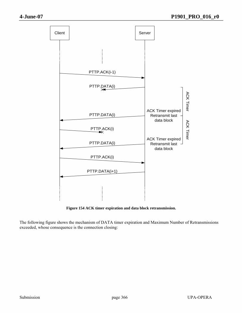
4-June-07 P1901_PRO_016_r0
Submission page 366 UPA-OPERA
Client Server
PTTP.ACK(i-1)
PTTP.DATA(i)
PTTP.ACK(i)
PTTP.DATA(i)
AC
K Tim
er
PTTP.DATA(i)
PTTP.ACK(i)
PTTP.DATA(i+1)
ACK Timer expiredRetransmit last
data block
ACK Timer expiredRetransmit last
data block
AC
K Timer
Figure 154 ACK timer expiration and data block retransmission.
The following figure shows the mechanism of DATA timer expiration and Maximum Number of Retransmissions exceeded, whose consequence is the connection closing:

4-June-07 P1901_PRO_016_r0
Submission page 367 UPA-OPERA
Client Server
PTTP.ACK(i-1)
PTTP.DATA(i)
PTTP.ACK(i)
Maximum Numberof Retransmissions
exceededClose connection
PTTP.DATA(i)
DATA Timerexpired
Close connection
PTTP.DATA(i)
AC
K Tim
er
DA
TA T
imer
AC
K Tim
er
ACK Timer expiredRetransmit last
data block
ACK Timer expiredRetransmit last
data block
AC
K Tim
er
ACK Timer expiredRetransmit last
data block
Max_R
etransmissions · A
CK
_Timer
PTTP.DATA(i)
Figure 155 DATA timer expiration and Maximum Number of Retransmissions exceeded.
12.2.5.3 PTTP Packets Format
All the packets used by the PTTP protocol are encapsulated with the CCP format, with Type0 0x07. The Type1 field indicates the type of packet within the PTTP protocol:
• 0x06 RRQ (Establish connection)
• 0x07 Data
• 0x08 Data Ack

4-June-07 P1901_PRO_016_r0
Submission page 368 UPA-OPERA
The data field contains the block number and/or data to transmit.
12.2.5.3.1 RRQ packet
Dest MAC Src MAC Payload
0xAA
0xAA
0x03
0x00
0x07
Leng
th
0x13
0x9D
0x06
TPID
TCI
Figure 156 PTTP RRQ packet format
The destination address is the Multicast address 0x01139D000000 defined by the CCP protocol. When a node receives such a packet, it must not be forwarded.
12.2.5.3.2 DATA packet
Dest MAC Src MAC Payload
0xA
A0x
AA
Data (0-1024 bytes)
0x03
0x00
0x07
Leng
th
0x13
0x9D
0x07
TP
ID
TC
I
Block Number
Figure 157 PTTP DATA packet format
The destination and source address are the client and server MAC addresses respectively.
The Type1 field indicates this is a data packet. Next to this field, it is the data block number, and finally the data block. The data field can be empty if the DATA packet is the last packet of the transfer.
12.2.5.3.3 DATA ACK packet

4-June-07 P1901_PRO_016_r0
Submission page 369 UPA-OPERA
Figure 158 PTTP DATA ACK packet format
The destination and source address are the server and client MAC addresses respectively.
The Type1 field indicates this is a data ack packet. Next to this field, it is the acknowledged data block number.
12.2.5.4 Translation Table DATA format
The Translation Table data follows a specific format. It is a set of one or more parameter items. A parameter item is defined as follows:
ParameterCode ParameterValue
1 byte 0 ... n bytes
Index
2 bytes
TT Parameter Item (4 + n bytes)
Size
1 byte
Figure 159 Translation Table parameter item
The field Size is the number of bytes of the rest of parameter item (ParameterCode + Index + ParameterValue). The minimum value is thus 4. If the value is 0, it means that no more parameters are sent. It is mandatory to finish the Data block with a 0-size byte.
The ParameterCode is a 2-byte field. The first byte is reserved for future extensions. It defaults to 0x00. The second byte is the parameter code. The whole field identifies one and only one parameter.
The Index byte contains the index for list parameters (from 1 to 127). It is 0 for scalar parameters.
The ParameterValue contains the value for that parameter. Its format depends on the ParameterCode and may be of any type such as int8, int16, int32, string…
The next parameters are available:
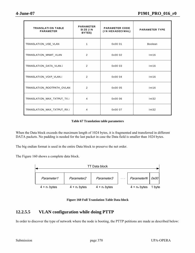
4-June-07 P1901_PRO_016_r0
Submission page 370 UPA-OPERA
TRANSLATION TABLE PARAMETER
PARAMETER SIZE (IN BYTES)
PARAMETER CODE (IN HEXADECIMAL)
PARAMETER TYPE
TRANSLATION_USE_VLAN 1 0x00 01 Boolean
TRANSLATION_MNMT_VLAN 2 0x00 02 Int16
TRANSLATION_DATA_VLAN.i 2 0x00 03 Int16
TRANSLATION_VOIP_VLAN.i 2 0x00 04 Int16
TRANSLATION_ROOTPATH_OVLAN 2 0x00 05 Int16
TRANSLATION_MAX_TXTPUT_TX.i 4 0x00 06 Int32
TRANSLATION_MAX_TXTPUT_RX.i 4 0x00 07 Int32
Table 67 Translation table parameters
When the Data block exceeds the maximum length of 1024 bytes, it is fragmented and transferred in different DATA packets. No padding is needed for the last packet in case the Data field is smaller than 1024 bytes.
The big endian format is used in the entire Data block to preserve the net order.
The Figure 160 shows a complete data block.
Parameter2
4 + n1 bytes
0x00
TT Data block
Parameter1
1 byte
Parameter3 ParameterN. . .
4 + n2 bytes 4 + n3 bytes 4 + nN bytes
Figure 160 Full Translation Table Data block
12.2.5.5 VLAN configuration while doing PTTP
In order to discover the type of network where the node is booting, the PTTP petitions are made as described below:

4-June-07 P1901_PRO_016_r0
Submission page 371 UPA-OPERA
• Step 1: A PTTP request is made without VLANs and waits for a response. If there is response, stay without VLAN.
• Step 2: Then it switches to VLAN mode and makes a PTTP request using VLAN tag #1 (reserved in the IEEE P1901 network) and waits for response. If there is response, stay with VLAN.
Step 3: Back to step 1.
To accomplish this, the VLAN #1 must be accepted in the node that acts as PTTP master.
12.2.5.6 PTTP packets forwarding
When a node receives a PTTP RRQ packet, the packet is not treated as multicast to avoid packet storms.
In transmission, the request is forwarded to all active interfaces in order to reach any active PTTP available server.
12.2.6 Translation Table
The translation table allows particularizing configuration files for a given network sector. Auto-configuration file is parametric, and the same for a given user category. Different sectors have different Translation Tables and each node combines its configuration file with the translation table to obtain its particular setting in VLAN/OVLAN and QoS terms.
The parameters cointained in the translation table are shown in 12.2.5.4.
The next figure shows the use of the translation table.
Configuration File
VLAN= %DTVL
%DTVL =13 %DTVL =14
S S
VLAN=13 VLAN=14
User A Sector 1
User A Sector 2
Translation table Translation table
Figure 161 Translation table example

4-June-07 P1901_PRO_016_r0
Submission page 372 UPA-OPERA
12.2.7 Auto-configuration & Networking
12.2.7.1 VLAN Network
The network model is described as follows:
• The BPL network is a switched network with different VLAN tags.
• BPL management protocols (PTTP, ABLP, etc.) use VLAN 1, while high-level management protocols (DHCP, TFTP, HTTP, NTP, SNMP, etc.) use the management VLAN configured by the auto-configuration procedure. The Management VLAN may be different in different LV cells.
• The end user node receives untagged traffic from the external interface and this traffic is tagged with the correct Data VLAN according to the ISP operator that the customer belongs to. So there can be more than one Data VLAN per LV cell.
• The end user node generates traffic from VoIP tagged with the correct VoIP VLAN according to the voice operator that the customer belongs to. So there can be more than one VoIP VLAN per LV cell.
• It is possible to add private VLANs between specific customers that do not belong to any ISP or voice operator. In this case, VLAN trunks must be defined in the intermediary equipment in order to allow all of that tagged traffic.
All of the traffic is tagged inside the BPL network.
Each node must receive its VLAN configuration inside the auto-configuration file. In addition to this, and in order to reduce the number of auto-configuration files, there will be a translation table transferred between nodes which. The translation table contains information about the Management, Data and VoIP VLANs used in a LV cell.
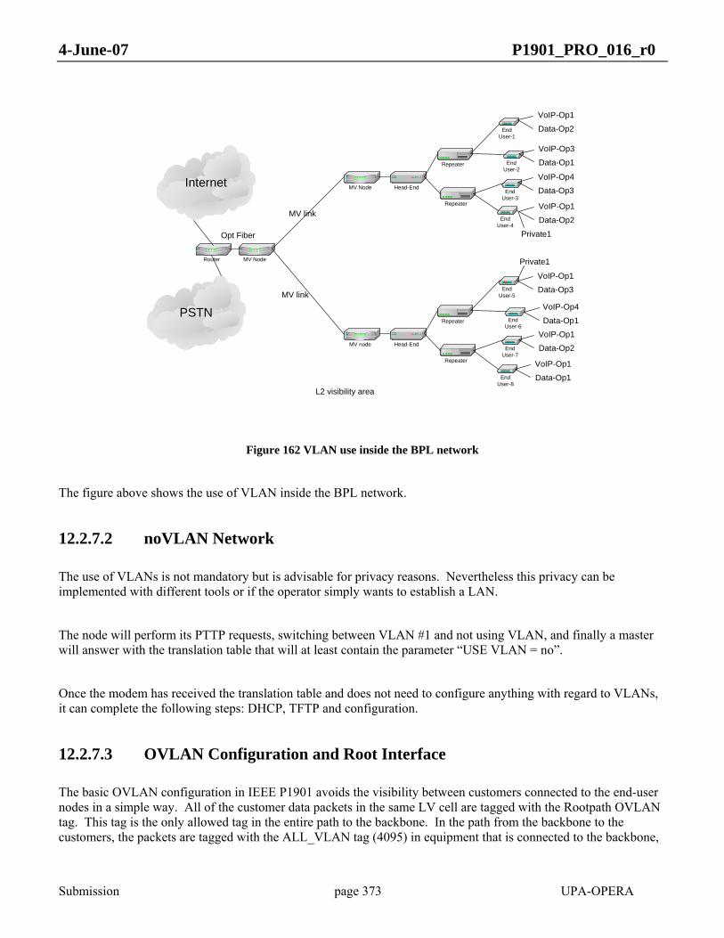
4-June-07 P1901_PRO_016_r0
Submission page 373 UPA-OPERA
PSTN
Internet Head-End
Repeater
Repeater
MV Node
Head-End
Repeater
Repeater
MV node
MV Node
MV link
MV link
Router
L2 visibility area
End User-1
End User-2
End User-3
End User-4
End User-5
End User-6
End User-7
End User-8
VoIP-Op1
Data-Op1
VoIP-Op1Data-Op2
VoIP-Op4
Data-Op1
VoIP-Op1Data-Op3
Private1
VoIP-Op1
Data-Op2
Private1
VoIP-Op3Data-Op1
VoIP-Op1
Data-Op2
VoIP-Op4Data-Op3
Opt Fiber
Figure 162 VLAN use inside the BPL network
The figure above shows the use of VLAN inside the BPL network.
12.2.7.2 noVLAN Network
The use of VLANs is not mandatory but is advisable for privacy reasons. Nevertheless this privacy can be implemented with different tools or if the operator simply wants to establish a LAN.
The node will perform its PTTP requests, switching between VLAN #1 and not using VLAN, and finally a master will answer with the translation table that will at least contain the parameter “USE VLAN = no”.
Once the modem has received the translation table and does not need to configure anything with regard to VLANs, it can complete the following steps: DHCP, TFTP and configuration.
12.2.7.3 OVLAN Configuration and Root Interface
The basic OVLAN configuration in IEEE P1901 avoids the visibility between customers connected to the end-user nodes in a simple way. All of the customer data packets in the same LV cell are tagged with the Rootpath OVLAN tag. This tag is the only allowed tag in the entire path to the backbone. In the path from the backbone to the customers, the packets are tagged with the ALL_VLAN tag (4095) in equipment that is connected to the backbone,
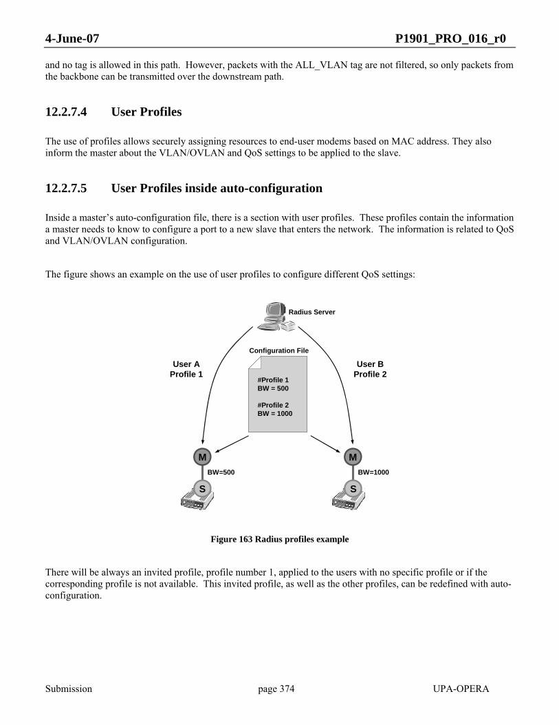
4-June-07 P1901_PRO_016_r0
Submission page 374 UPA-OPERA
and no tag is allowed in this path. However, packets with the ALL_VLAN tag are not filtered, so only packets from the backbone can be transmitted over the downstream path.
12.2.7.4 User Profiles
The use of profiles allows securely assigning resources to end-user modems based on MAC address. They also inform the master about the VLAN/OVLAN and QoS settings to be applied to the slave.
12.2.7.5 User Profiles inside auto-configuration
Inside a master’s auto-configuration file, there is a section with user profiles. These profiles contain the information a master needs to know to configure a port to a new slave that enters the network. The information is related to QoS and VLAN/OVLAN configuration.
The figure shows an example on the use of user profiles to configure different QoS settings:
Configuration File
#Profile 1BW = 500
#Profile 2BW = 1000
S S
User AProfile 1
User BProfile 2
M M
Radius Server
BW=500 BW=1000
Figure 163 Radius profiles example
There will be always an invited profile, profile number 1, applied to the users with no specific profile or if the corresponding profile is not available. This invited profile, as well as the other profiles, can be redefined with auto-configuration.
4-June-07 P1901_PRO_016_r0
Submission page 375 UPA-OPERA
12.2.7.6 Working with RADIUS Authentication
When RADIUS authentication is active, the repeater or HE sends an Access-Request message to the RADIUS server, which checks if the MAC address corresponds to one that was accepted and, in that case, it responds with an Access-Accept message containing the profile number. Otherwise, the server replies with a RADIUS Access-Reject message and the authentication fails. If the authentication fails the slave will not join the BPL network.
Once authentication is achieved, the slave is authorized and a QoS and VLAN/OVLAN configuration takes place between the master and slave. The master uses the profile number to get these parameters. The slave uses the parameters inside the downloaded auto-configuration file. The slave node downloads the file during its auto-configuration process, after the RADIUS request on the master-side has been successful.
12.2.7.7 Working without RADIUS Authentication
If there is no RADIUS authentication, two ways of operation are possible.
The first one is ‘NO AUTHENTICATION’. The master will configure a default QoS and VLAN/OVLAN configuration (the invited profile) for the slave.
The other one is the use of an ‘AUTHORIZATION LIST’. With ‘ACCESSP_AUTHLIST_x’, up to 128 different users can be added with their related profiles. The user is searched for in that list, and if an entry matches with the new user, the QoS and VLAN/OVLAN configuration related to that entry is used for the new user. Otherwise, the user is rejected.
12.2.8 DHCP Support
12.2.8.1 DHCP Client
The IEEE P1901 nodes perform a DHCP request with extended custom options. So not only the basic IP configuration (IP address, netmask and gateway) is requested, but the client also requests three custom options in order to obtain the auto-configuration file:
• tftp-server-name: String with the IP address of the TFTP server.
• extensions-path-name: String with the path and file name of the auto-configuration file inside the TFTP server.
• PTTP-code: 32 bits integer that represents the PTTP behaviour:
o 0: Boot without VLANs and skip PTTP.
o 1: Keep on requesting PTTP (does nothing).
o [2-4095]: Boot with Management VLAN = PTTP-code. Skip PTTP.

4-June-07 P1901_PRO_016_r0
Submission page 376 UPA-OPERA
On the other hand, if the phone number has to be downloaded using DHCP, another custom option should be requested:
• phone-number: Text with the phone number.
12.2.8.2 DHCP Server
A DHCP server that supports DHCP extensions is needed in order to provide the different IEEE P1901 nodes with the custom options requested.
Warning: Although the two first custom options needed by the DHCP client are supposed to be standard, sometimes it is necessary to define the extensions-path-name option in the header of the dhcpd.conf file. The PTTP-code option is mandatory to define:
option extensions-path-name code 18 = string;
option PTTP-code code 120 = unsigned integer 32;
It is also necessary to define the phone-number in the header of the dhcpd.conf file, if the phone number of some CPEs will be configured via DHCP:
option phone-number code 135 = text;
12.2.9 RADIUS Support
Every IEEE P1901 master or repeater node may implement a RADIUS client in order to authenticate users (slaves) connected through the BPL to that node. The modem acts as a NAS, which requests authentication, gives authorization, and allocates resources.
12.2.9.1 RADIUS Client
The RADIUS client implemented in the IEEE P1901 nodes is configured through the auto-configuration file with three parameters:
• RADIUS server IP address
• RADIUS server UDP port
• Shared secret password between client and server
It also sends two RADIUS standard attributes within a RADIUS request:
• MAC address of the slave trying to join the network as User name.
4-June-07 P1901_PRO_016_r0
Submission page 377 UPA-OPERA
• MAC address of the master as NAS-Identifier.
12.3 Auto-configuration Parameters
12.3.1 Parameter Types
There are three types of parameters inside the auto-configuration file:
1. Scalar: PARAMETER = value
2. List: PARAMTER.index1 = value
3. Table: PARAMETER.index1.index2 = value
The first valid index for lists and tables is 1.
12.3.2 Parameter Format
The format of the parameters is:
• PARAMETER_LABEL[.x][.y] = value
for concrete parameter values
• PARAMETER_LABEL[.x][.y] = %parametric_value
for parametric parameter values
For example, the following parameter could be inside an end-user auto-configuration file:
• VLAN_DATA_TAG = 452
or
• VLAN_DATA_TAG = %DATA3
In the second case, the parametric value must be translated to its correct value using the translation table.
The following is a list with the syntax of the autoconfiguration parameters.
It is important that the order in which these parameters appear in the auto-configuration file is preserved.

4-June-07 P1901_PRO_016_r0
Submission page 378 UPA-OPERA
12.3.3 Auto-configuration parameter list
12.3.3.1 General Parameters
• GENERAL_USE_AUTOCONF = [YES | NO]
o Parameter: YES enables autoconf, NO disables it.
• GENERAL_TYPE = [HE | CPE | TDREPEATER]
o Parameter: Possible values are: HE (Head End), CPE (Customer Premises Equipment) and TDREPEATER (Time Division Repeater).
• GENERAL_FW_TYPE = [MV | LV | EU]
o Parameter: Possible values are: MV (Medium Voltage), LV (Low Voltage) and EU (End User).
• GENERAL_SIGNAL_MODE = [1 … m]
o Parameter: Configures the physical mode used by the modem. This value can reach from 1 to m, depending on the range of frequency used.
• GENERAL_SIGNAL_MODE_LIST.i = [1 … m]
o Parameter: This value can reach from 1 to m, depending on the range of frequency used.
• GENERAL_AUTHENTICATION = [RADIUS | AUTHLIST | NONE]
o Parameter: There are three possible values: RADIUS, ATHLIST and NONE. If RADIUS is selected, a RADIUS server will be in charge of accepting new users and assigning the profile. If AUTHLIST is selected, authentication will be done by checking a list provided in the auto-configuration file. If NONE is selected, all the users will be accepted
• GENERAL_STP = [YES | NO]
o Parameter: Enables (YES) or disables (NO) the Spanning Tree Protocol in the node. Enabled by default.
• GENERAL_COMMON_STP_EXTA = [YES | NO]
o Parameter: Enables (YES) or disables (NO) the Common STP feature in the Ethernet interface A (EXTA).
• GENERAL_COMMON_STP_EXTB = [YES | NO]
o Parameter: Enables (YES) or disables (NO) the Common STP feature in the Ethernet interface B (EXTB).
• GENERAL_IP_ADDRESS = <ddd.ddd.ddd.ddd>
o Parameter: The valid format is the dotted decimal notation (four decimal numbers separated by dots).

4-June-07 P1901_PRO_016_r0
Submission page 379 UPA-OPERA
• GENERAL_IP_NETMASK = <ddd.ddd.ddd.ddd>
o Parameter: The valid format is the dotted decimal notation (four decimal numbers separated by dots).
• GENERAL_IP_GATEWAY = <ddd.ddd.ddd.ddd>
o Parameter: The valid format is the dotted decimal notation (four decimal numbers separated by dots).
• GENERAL_IP_USE_DHCP = [YES | NO]
o Parameter: If Yes DHCP is used, if NO DHCP is not used.
12.3.3.2 AGC (Automatic Gain Control) Parameters
• AGC_TX_GAIN = [0 | 1]
o Parameter: Selecting 1, the default value, 12 dB are added to the reference gain. In case of 0 value, no extra gain is added (0 dB).
• AGC_RX_ENABLE = [0 | 1]
o Parameter: Enables (1) or disables (0) the hardware AGC.
• AGC_RX_FIX_GAIN = [0 … 7]
o Parameter: Eight values, from 0 to 7, are possible. Those values represent gains from 0 to 42 dB, respectively, added to the reference gain in steps of 6 dB.
• AGC_MAX_RX_GAIN = [0 … 7]
o Parameter: Eight values, from 0 to 7, are possible. Those values represent gains from 0 to 42 dB, respectively, added to the reference gain in steps of 6 dB. The default value is 7 (42 dB).
• AGC_MIN_RX_GAIN = [0 … 7]
o Parameter: Eight values, from 0 to 7, are possible. Those values represent gains from 0 to 42 dB, respectively, added to the reference gain in steps of 6 dB. The default value is 7 (42 dB).
12.3.3.3 RADIUS Parameters
• RADIUS_SERVER_IP = <ddd.ddd.ddd.ddd>
o Parameter: The valid format is the dotted decimal notation (four decimal numbers separated by dots).
• RADIUS_SERVER_PORT = ddddd
o Parameter: Port number

4-June-07 P1901_PRO_016_r0
Submission page 380 UPA-OPERA
• RADIUS_SHARED_SECRET = <string>
o Parameter: ‘shared_secret’ (string, limited to 16 characters, of the shared secret)
12.3.3.4 Class of Service (CoS) Parameters
• COS_CUSTOM_CRITERION_OFFSET.i = [1 … 531]
o Parameter: Values from 1 to 531 are possible.
• COS_CUSTOM_CRITERION_PATTERN.i = 0xXXXXXXXXXXXXXXXX
o Parameter: The value must be specified with 16 hexadecimal digits.
• COS_CUSTOM_CRITERION_BITMASK.i = 0xXXXXXXXXXXXXXXXX
o Parameter: The value must be specified with 16 hexadecimal digits.
• COS_CUSTOM_CRITERION_CLASSES_OFFSET.i = [1 … 531]
o Parameter: Values from 1 to 531 are possible.
• COS_CUSTOM_CRITERION_CLASSES_BITMASK.i i = 0xXXXXXXXXXXXXXXXX
o Parameter: The value must be specified with 16 hexadecimal digits.
• COS_CUSTOM_CRITERION_CLASSES_PATTERN.i.j i=0xXXXXXXXXXXXXXXXX
o Parameter: The value must be specified with 16 hexadecimal digits
• COS_CUSTOM_CRITERION_CLASSES_PRIO.i.j = [0 … 7]
o Parameter: Values from 0 to 7 are allowed.
• COS_CRITERION.k = [8021P | TOS | CUSTOM1 | CUSTOM2]
o Parameter: There are two predefined criteria (8021P, based on IEEE 802.1p VLAN tag priority field, and TOS, based on IP type of service), and two custom criteria (CUSTOM1 and CUSTOM2), defined with the parameters above (COS_CUSTOM_CRITERION_xxx).
• COS_DEFAULT_PRIO = [0 … 7]
o Parameter: Values from 0 to 7 are allowed.
12.3.3.5 Quality of Service (QoS) Parameters
• QOS_ENABLE = [YES | NO]
o Parameter: Enables (YES) or disables (NO) the quality of service in the node.
• QOS_PRIOACK.prio+1 = [0 | 1]

4-June-07 P1901_PRO_016_r0
Submission page 381 UPA-OPERA
o Parameter: This list enables (1) or disables (0) the Layer 2 ACK protocol depending on the priority level transmitted by the modem (priority levels: prio = 0 … 7).
• QOS_PRIORSV.prio+1 = [CBR | VBR | BE]
o Parameter: Type of reservation for each priority
12.3.3.5.1 Slave Node Parameters (CPE)
• QOS_UPBWLIMIT = [YES | NO]
o Parameter: Enables (YES) or disables (NO) the transmission bandwidth limitation in a slave.
• QOS_CLASSES.prio+1 = [VOIP | VIDEO | DATAH | DATAL]
o Parameter: Sets the type of application for each service class
12.3.3.5.2 Master Node Parameters (HE or REPEATER)
• QOS_LATENCY_STEP = [20 … 400]
o Parameter: Values in ms, from 20 to 400.
• QOS_BW_POLICY = [0 | 1]
o Parameter: A value of 0 corresponds to Fair mode, and 1 to Priority-based mode.
• QOS_LATENCY.prio+1 = [1 | 2 | 4 | 8]
o Parameter: Priority levels: prio = 0 … 7. Possible values are: 1, 2, 4 and 8.
12.3.3.6 Profiles Parameters
• PROFILE_MAX_TXPUT_TX.i = dddd (in kbps)
o Parameter: Number of kbps)
• PROFILE_MAX_TXPUT_RX.i = dddd (in kbps)
o Parameter: Number of kbps)
• PROFILE_PRIORITIES.i = [0x00-0xFF]
o Parameter: ‘0xXX’ (hexadecimal number from 00 to FF)
• PROFILE_MNMT_VLAN.i = [2-4093] | %<PARAMETRIC VALUE>
o Parameter: Number from 2 to 4093 or ‘%Parameter_name’ (parametric value preceded by a %)
• PROFILE_DATA_VLAN.i = [2-4093] | %<PARAMETRIC VALUE>
4-June-07 P1901_PRO_016_r0
Submission page 382 UPA-OPERA
o Parameter: Number from 2 to 4093 or ‘%Parameter_name’ (parametric value preceded by a %)
• PROFILE_VOIP_VLAN.i = [2-4093] | %<PARAMETRIC VALUE>
o Parameter: Number from 2 to 4093 or ‘%Parameter_name’ (parametric value preceded by a %)
• PROFILE_VLAN_ADD_TAG.i.j = [2-4093] or parametric
o Parameter: Number from 2 to 4093 or ‘%Parameter_name’ (parametric value preceded by a %)
• PROFILE_VLAN_IS_ALLOWED_IFACE_USER.i = [yes/no]
o Parameter: ‘yes’ (to set the list as allowed) or ‘no’ (to set the list as forbidden)
• PROFILE_VLAN_TAGGED_ONLY_IFACE_USER.i = [yes/no]
o Parameter: ‘yes’ (to drop input packets without VLAN tag) or ‘no’ (to not drop input packets without VLAN tag)
• PROFILE_VLAN_OUTFORMAT_TAG_IFACE_USER.i = [yes/no]
o Parameter: ‘yes’ (to send packets with VLAN tag) or ‘no’ (to not send packets with VLAN tag)
• PROFILE_OVLAN_ADD_TAG.i.j = [2-4094] or parametric
o Parameter: Number from 2 to 4094 or ‘%Parameter_name’ (parametric value preceded by a %)
• PROFILE_OVLAN_IS_ALLOWED_IFACE_USER.i = [yes/no]
o Parameter: ‘yes’ (to mark the list as allowed) or ‘no’ (to mark the list as forbidden)
• PROFILE_OVLAN_TAGGED_ONLY_IFACE_USER.i = [yes/no]
o Parameter: ‘yes’ (to drop input packets without OVLAN tag) or ‘no’ (to not drop input packets without OVLAN tag)
• PROFILE_OVLAN_OUTFORMAT_TAG_IFACE_USER.i = [yes/no]
o Parameter: ‘yes’ (to send packets with OVLAN tag) or ‘no’ (to not send packets with OVLAN tag)
• PROFILE_UPBWLIMIT.i = [YES|NO]
o Parameter: ‘yes’ (to limit the upstream) or ‘no’ (to not limit the upstream)
• PROFILE_DWBWLIMIT.i = [YES|NO]
o Parameter: ‘yes’ (to limit the downstream) or ‘no’ (to not limit the downstream)
12.3.3.7 Translation Table Parameters
• TRANSLATION_MNMT_VLAN = [2-4093]
4-June-07 P1901_PRO_016_r0
Submission page 383 UPA-OPERA
o Parameter: Number from 2 to 4093
• TRANSLATION_DATA_VLAN.i = [2-4093]
o Parameter: Number from 2 to 4093
• TRANSLATION_VOIP_VLAN.i = [2-4093]
o Parameter: Number from 2 to 4093
• TRANSLATION_ROOTPATH_OVLAN = [2-4094]
o Parameter: Number from 2 to 4094
12.3.3.8 VLAN Parameters
• VLAN_ENABLE = [yes|no]
o Parameter: ‘yes’ (to enable VLAN use) or ‘no’ (to disable VLAN use)
• VLAN_MNMT_TAG = [2-4093] | %<PARAMETRIC VALUE>
o Parameter: Number from 2 to 4093 or ‘%Parameter name’ (parametric value preceded by a %)
• VLAN_MNMT_PRIO = [0-7]
o Parameter: Number from 0 to 7
• VLAN_DATA_TAG = [2-4093] | %<PARAMETRIC VALUE>
o Parameter: Number from 2 to 4093 or ‘%Parameter_name’ (parametric value preceded by a %)
• VLAN_DATA_PRIO = [0-6]
o Parameter: Number from 0 to 6
• VLAN_VOIP_TAG = [2-4093] | %<PARAMETRIC VALUE>
o Parameter: Number from 2 to 4093 or ‘%Parameter_name‘ (parametric value preceded by a %)
• VLAN_VOIP_PRIO = [0-7]
o Parameter: Number from 0 to 7
• VLAN_VSIG_PRIO = [0-7]
o Parameter: Number from 0 to 7
• VLAN_TRUNK.i = [2-4093]
o Parameter: Number from 2 to 4093

4-June-07 P1901_PRO_016_r0
Submission page 384 UPA-OPERA
• VLAN_RETAG_EXTA_SRC = [0 | 2-4095]
o Parameter: ‘0’ (in order to disable retagging in interface) or Number from 2 to 4095.
• VLAN_RETAG_EXTA_DST = [0 | 2-4095]
o Parameter: ‘0’ (in order to disable retagging in interface) or Number from 2 to 4095
• VLAN_RETAG_EXTB_SRC = [0 | 2-4095]
o Parameter: ‘0’ (in order to disable retagging in interface) or Number from 2 to 4095
• VLAN_RETAG_EXTB_DST = [0 | 2-4095]
o Parameter: ‘0’ (in order to disable retagging in interface) or Number from 2 to 4095
12.3.3.9 OVLAN Parameters
• OVLAN_ENABLE = [yes|no]
o Parameter: ‘yes’ (to enable OVLAN use) or ‘no’ (to disable OVLAN use)
• OVLAN_DATA_TAG = [2-4094] | %ROOTPATH_OVLAN
o Parameter: Number from 2 to 4093 or ‘%ROOTPATH_OVLAN’ (use the OVLAN Rootpath value)
• OVLAN_TRUNK.i = [2-4094]
o Parameter: Number from 2 to 4094
12.3.3.10 Access Protocol Parameters
• AP_MIN_NUMBER_HOPS = [0|1|…]
o Parameter: Number from 0
• AP_FORBID_MASTER.i = 0xXXXXXXXXXXXX
o Parameter: ‘0xXXXXXXXXXXXX’ (MAC address of forbidden master)
• AP_PREFER_MASTER = 0xXXXXXXXXXXXX
o Parameter: ‘0xXXXXXXXXXXXX’ (MAC address of preferred master)
• AP_FIX_MASTER = ‘0xXXXXXXXXXXXX’
o Parameter: 0xXXXXXXXXXXXX (MAC address of fixed master)
• AP_CHECK_BEST_MASTER_ENABLE = [yes|no]

4-June-07 P1901_PRO_016_r0
Submission page 385 UPA-OPERA
o Parameter: ‘yes’ (to enable checking of best master periodically after connecting with one) or ‘no’ (to disable the checking of better masters after connecting to one).
• AP_CHECK_BEST_MASTER_PERIOD = <time>
o Parameter: Number of minutes
• AP_CURRENT_MASTER_MIN_BPS = <bps_thr>
o Parameter: Number of bits per symbol
• AP_NEW_MASTER_MIN_BPS = <bps_thr>
o Parameter: Number of bits per symbol
• ACCESSP_AUTHLIST_MAC.i = 0xXXXXXXXXXXXX
o Parameter: ‘0xXXXXXXXXXXXX’ (MAC address authorized to connect)
• ACCESSP_AUTHLIST_PROFILE.i = [1-16]
o Parameter: Number of the profile related to a MAC authorized
• ACCESSP_AUTHLIST_FWTYPE.i = [MV|LV|EU]
o Parameter: ‘MV’ (medium voltage) or ‘LV’ (low voltage) or ‘EU’ (End User)
12.3.3.11 STP Parameters
• STP_PRIO = [0 … 65535]
o Parameter: Valid values range from 0 to 65535.
• STP_PORT.i = [EXTA | EXTB | BPL]
o Parameter: Three possible values: EXTA, EXTB and BPL (i = 1,2 or 3).
• STP_PORT_PRIO.i = [0 … 255]
o Parameter: Valid values range from 0 to 255 (i = 1,2 or 3).
• STP_PORT_COST.i = [0 … 4294967295]
o Parameter: Valid values range from 0 to 4294967295 (i = 1,2 or 3).
• STP_HELLO_TIME = [10 … 40]
o Parameter: Valid values range from 10 to 40.
• STP_MAX_AGE = [10 … 40]
o Parameter: Valid values range from 10 to 40.

4-June-07 P1901_PRO_016_r0
Submission page 386 UPA-OPERA
• STP_FORWARD_DELAY = [40 … 300]
o Parameter: Valid values range from 40 to 300.
• STP_FRONTIER = [EXTA | EXTB | NONE]
o Parameter: Valid values are: EXTA (Ethernet interface A), EXTB (Ethernet interface B) and NONE (Spanning Tree Frontier disabled).
• STP_MODE = [STP | RSTP]
o Parameter: Possible values: STP selects STP or RSTP selects RSTP.
12.3.3.12 VoIP Parameters
• VOIP_ENABLE = [ENABLED | DISABLED]
o Parameter: This parameter enables (ENABLED) or disables (DISABLED) the VoIP service.
• VOIP_GATEKEEPERIP = <ddd.ddd.ddd.ddd>
o Parameter: The valid format is the dotted decimal notation (four decimal numbers separated by dots).
• VOIP_LINE1NUMBER = number
o Parameter: This parameter is a string (maximum string length is 20 characters) (e.g. “VOIP_LINE1NUMBER = 612345678”).
• VOIP_DIALPLAN = ([0 … 9, ‘T’, ‘X’, ‘.’, ‘|’])
o Parameter: This parameter is a string with maximum length is 200 characters (e.g. “VOIP_DIALPLAN = (9XXXXXXXX|6XXXXXXXX|00X.T)”.
• VOIP_INBANDDTMF = [ENABLED | DISABLED]
o Parameter: This parameter enables (ENABLED) or disables (DISABLED) in-band DTMF feature.
• VOIP_OUTOFBANDDTMF = [ENABLED | DISABLED]
o Parameter: This parameter enables (ENABLED) or disables (DISABLED) out-of-band DTMF feature.
• VOIP_KEYPADTYPE = [KEYPADTYPE_NONE | KEYPADTYPE_H225 | KEYPADTYPE_H245ALPHANUMERIC | KEYPADTYPE_H245SIGNAL | KEYPADTYPE_RFC2833]
o Parameter: This parameter is a string (up to 30 characters). Valid values are the following:
o KEYPADTYPE_H225: H.225/Q.931 User Info field (Keypad facility information element)
4-June-07 P1901_PRO_016_r0
Submission page 387 UPA-OPERA
o KEYPADTYPE_H245ALPHANUMERIC: H.245 User Input Indication (UII) Alphanumeric message
o KEYPADTYPE_H245SIGNAL: H.245 User Input Indication (UII) Signal Type message
o KEYPADTYPE_RFC2833: RTP stream as defined in RFC 2833
o KEYPADTYPE_NONE: no out-of-band signalling
• VOIP_CALLSIGPORT1 = [1025 … 65530]
o Parameter: Valid values range from 1025 to 65530.
• VOIP_G711USS = [YES | NO]
o Parameter: Selects whether silence suppression for G.711 μ-law is enabled (YES) or not (NO).
• VOIP_G711UPACK = [2 … 4]
o Parameter: Valid values range from 2 (20 ms) to 4 (40 ms).
• VOIP_G711ASS = [YES | NO]
o Parameter: Selects whether silence suppression for G.711 A-law is enabled (YES) or not (NO).
• VOIP_G711APACK = [2 … 4]
o Parameter: Valid values range from 2 (20 ms) to 4 (40 ms).
• VOIP_JB_TYPE = [FIXED | ADAPTIVE]
o Parameter: Selects either adaptive (ADAPTIVE) or fixed (FIXED) jitter buffer.
• VOIP_FJB_DELAY = [1 … 10] * 10
o Parameter: Valid values range from 10 to 100 ms.
• VOIP_AJB_MAXDELAY = [1 … 19] * 10
o Parameter: Valid values range from 10 to 190 ms.
• VOIP_G729ON = [YES | NO]
o Parameter: Selects whether G.729 codec is enabled (YES) or not (NO).
• VOIP_G729SS = [YES | NO]
o Parameter: Selects whether G.729 silence enabled is supported (YES) or not (NO).
• VOIP_G729PACK = [2 … 4]
o Parameter: Valid values range from 2 (20 ms) to 4 (40 ms).
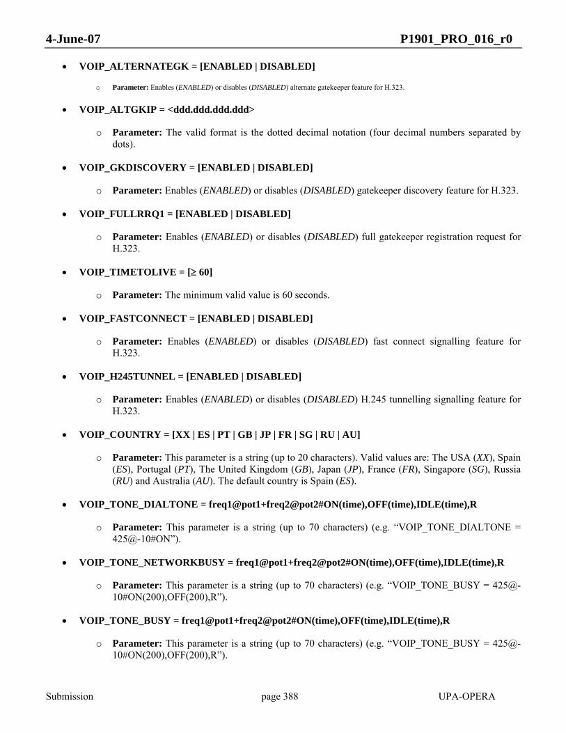
4-June-07 P1901_PRO_016_r0
Submission page 388 UPA-OPERA
• VOIP_ALTERNATEGK = [ENABLED | DISABLED]
o Parameter: Enables (ENABLED) or disables (DISABLED) alternate gatekeeper feature for H.323.
• VOIP_ALTGKIP = <ddd.ddd.ddd.ddd>
o Parameter: The valid format is the dotted decimal notation (four decimal numbers separated by dots).
• VOIP_GKDISCOVERY = [ENABLED | DISABLED]
o Parameter: Enables (ENABLED) or disables (DISABLED) gatekeeper discovery feature for H.323.
• VOIP_FULLRRQ1 = [ENABLED | DISABLED]
o Parameter: Enables (ENABLED) or disables (DISABLED) full gatekeeper registration request for H.323.
• VOIP_TIMETOLIVE = [≥ 60]
o Parameter: The minimum valid value is 60 seconds.
• VOIP_FASTCONNECT = [ENABLED | DISABLED]
o Parameter: Enables (ENABLED) or disables (DISABLED) fast connect signalling feature for H.323.
• VOIP_H245TUNNEL = [ENABLED | DISABLED]
o Parameter: Enables (ENABLED) or disables (DISABLED) H.245 tunnelling signalling feature for H.323.
• VOIP_COUNTRY = [XX | ES | PT | GB | JP | FR | SG | RU | AU]
o Parameter: This parameter is a string (up to 20 characters). Valid values are: The USA (XX), Spain (ES), Portugal (PT), The United Kingdom (GB), Japan (JP), France (FR), Singapore (SG), Russia (RU) and Australia (AU). The default country is Spain (ES).
• VOIP_TONE_DIALTONE = freq1@pot1+freq2@pot2#ON(time),OFF(time),IDLE(time),R
o Parameter: This parameter is a string (up to 70 characters) (e.g. “VOIP_TONE_DIALTONE = 425@-10#ON”).
• VOIP_TONE_NETWORKBUSY = freq1@pot1+freq2@pot2#ON(time),OFF(time),IDLE(time),R
o Parameter: This parameter is a string (up to 70 characters) (e.g. “VOIP_TONE_BUSY = 425@-10#ON(200),OFF(200),R”).
• VOIP_TONE_BUSY = freq1@pot1+freq2@pot2#ON(time),OFF(time),IDLE(time),R
o Parameter: This parameter is a string (up to 70 characters) (e.g. “VOIP_TONE_BUSY = 425@-10#ON(200),OFF(200),R”).
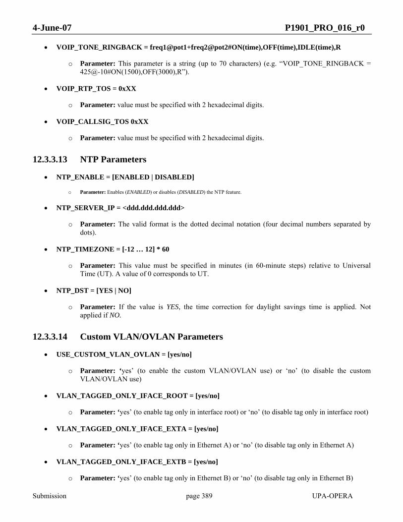
4-June-07 P1901_PRO_016_r0
Submission page 389 UPA-OPERA
• VOIP_TONE_RINGBACK = freq1@pot1+freq2@pot2#ON(time),OFF(time),IDLE(time),R
o Parameter: This parameter is a string (up to 70 characters) (e.g. “VOIP_TONE_RINGBACK = 425@-10#ON(1500),OFF(3000),R”).
• VOIP_RTP_TOS = 0xXX
o Parameter: value must be specified with 2 hexadecimal digits.
• VOIP_CALLSIG_TOS 0xXX
o Parameter: value must be specified with 2 hexadecimal digits.
12.3.3.13 NTP Parameters
• NTP_ENABLE = [ENABLED | DISABLED]
o Parameter: Enables (ENABLED) or disables (DISABLED) the NTP feature.
• NTP_SERVER_IP = <ddd.ddd.ddd.ddd>
o Parameter: The valid format is the dotted decimal notation (four decimal numbers separated by dots).
• NTP_TIMEZONE = [-12 … 12] * 60
o Parameter: This value must be specified in minutes (in 60-minute steps) relative to Universal Time (UT). A value of 0 corresponds to UT.
• NTP_DST = [YES | NO]
o Parameter: If the value is YES, the time correction for daylight savings time is applied. Not applied if NO.
12.3.3.14 Custom VLAN/OVLAN Parameters
• USE_CUSTOM_VLAN_OVLAN = [yes/no]
o Parameter: ‘yes’ (to enable the custom VLAN/OVLAN use) or ‘no’ (to disable the custom VLAN/OVLAN use)
• VLAN_TAGGED_ONLY_IFACE_ROOT = [yes/no]
o Parameter: ‘yes’ (to enable tag only in interface root) or ‘no’ (to disable tag only in interface root)
• VLAN_TAGGED_ONLY_IFACE_EXTA = [yes/no]
o Parameter: ‘yes’ (to enable tag only in Ethernet A) or ‘no’ (to disable tag only in Ethernet A)
• VLAN_TAGGED_ONLY_IFACE_EXTB = [yes/no]
o Parameter: ‘yes’ (to enable tag only in Ethernet B) or ‘no’ (to disable tag only in Ethernet B)

4-June-07 P1901_PRO_016_r0
Submission page 390 UPA-OPERA
• VLAN_TAGGED_ONLY_IFACE_PL_X = [yes/no]
Being X from 0 to 128
o Parameter: ‘yes’ (to enable tag only in BPL ports) or ‘no’ (to disable tag only in BPL ports)
• VLAN_OUTFORMAT_TAG_IFACE_ROOT = [yes/no]
o Parameter: ‘yes’ (to tag output in root interface) or ‘no’ (to disable tag output in root interface)
• VLAN_OUTFORMAT_TAG_IFACE_EXTA = [yes/no]
o Parameter: ‘yes’ (to tag output in Ethernet A) or ‘no’ (to disable tag output in Ethernet A)
• VLAN_OUTFORMAT_TAG_IFACE_EXTB = [yes/no]
o Parameter: ‘yes’ (to tag output in Ethernet B) or ‘no’ (to disable tag output in Ethernet B)
• VLAN_OUTFORMAT_TAG_IFACE_PL_X = [yes/no]
Being X from 0 to 128
o Parameter: ‘yes’ (to tag output in BPL ports) or ‘no’ (to disable tag output in BPL ports)
• VLAN_PVID_PL = [2-4095]
o Parameter: Number from 2 to 4095
• VLAN_PVID_EXTA = [2-4095]
o Parameter: Number from 2 to 4095
• VLAN_PVID_EXTB = [2-4095]
o Parameter: Number from 2 to 4095
• VLAN_PVID_FW = [2-4095]
o Parameter: Number from 2 to 4095
• VLAN_DEFAULT_PRIO_PL_X = [0-7]
Being X from 0 to 128
o Parameter: Number from 0 to 7
• VLAN_DEFAULT_PRIO_EXTA = [0-7]
o Parameter: Number from 0 to 7
• VLAN_DEFAULT_PRIO_EXTB = [0-7]

4-June-07 P1901_PRO_016_r0
Submission page 391 UPA-OPERA
o Parameter: Number from 0 to 7
• VLAN_DEFAULT_PRIO_FW = [0-7]
o Parameter: Number from 0 to 7
• VLAN_IS_ALLOWED_IFACE_ROOT = [yes/no]
o Parameter: ‘yes’ (to set list as allowed) or ‘no’ (to set list as forbidden)
• VLAN_LIST_IFACE_ROOT.i = [2-4095]
o Parameter: Number from 2 to 4095
• VLAN_IS_ALLOWED_IFACE_EXTA = [yes/no]
o Parameter: ‘yes’ (to set list as allowed) or ‘no’ (to set list as forbidden)
• VLAN_LIST_IFACE_EXTA.i = [2-4095]
o Parameter: Number from 2 to 4095
• VLAN_IS_ALLOWED_IFACE_EXTB = [yes/no]
o Parameter: ‘yes’ (to set list as allowed) or ‘no’ (to set list as forbidden)
• VLAN_LIST_IFACE_EXTB.i = [2-4095]
o Parameter: Number from 2 to 4095
• VLAN_IS_ALLOWED_IFACE_PL_X = [yes/no]
Being X from 0 to 128
o Parameter: ‘yes’ (to set list as allowed) or ‘no’ (to set list as forbidden)
• VLAN_LIST_IFACE_PL_Xi = [2-4095]
Being X from 0 to 128
o Parameter: Number from 2 to 4095
• OVLAN_TAGGED_ONLY_IFACE_ROOT = [yes/no]
o Parameter: ‘yes’ (to accept only tagged packets at root interface) or ‘no’ (to accept any packet at root interface)
• OVLAN_TAGGED_ONLY_IFACE_PL_X= [yes/no]
Being X from 0 to 128

4-June-07 P1901_PRO_016_r0
Submission page 392 UPA-OPERA
o Parameter: ‘yes’ (to accept only tagged packets at BPL ports) or ‘no’ (to accept any packet at BPL ports)
• OVLAN_OUTFORMAT_TAG_IFACE_ROOT = [yes/no]
o Parameter: ‘yes’ (to introduce a tag in output packets at root interface) or ‘no’ (to not introduce a tag in output packets at root interface)
• OVLAN_OUTFORMAT_TAG_IFACE_PL_X = [yes/no]
Being X from 0 to 128
o Parameter: ‘yes’ (to introduce a tag in output packets at BPL ports) or ‘no’ (to not introduce a tag in output packets at BPL ports)
• OVLAN_POVID_PL_X = [2-4095]
Being X from 0 to 128
o Parameter: Number from 2 to 4095
• OVLAN_POVID_EXTA = [2-4095]
o Parameter: Number from 2 to 4095
• OVLAN_POVID_EXTB = [2-4095]
o Parameter: Number from 2 to 4095
• OVLAN_POVID_FW = [2-4095]
o Parameter: Number from 2 to 4095
• OVLAN_IS_ALLOWED_IFACE_ROOT = [yes/no]
o Parameter: ‘yes’ (to set the root interface list as allowed) or ‘no’ (to set the root interface list as forbidden)
• OVLAN_LIST_IFACE_ROOT.i = [2-4095]
o Parameter: Number from 2 to 4095
• OVLAN_IS_ALLOWED_IFACE_EXTA = [yes/no]
o Parameter: ‘yes’ (to set the Ethernet A interface list as allowed) or ‘no’ (to set the Ethernet A interface list as forbidden)
• OVLAN_LIST_IFACE_EXTA.i = [2-4095]
o Parameter: Number from 2 to 4095
• OVLAN_IS_ALLOWED_IFACE_EXTB = [yes/no]

4-June-07 P1901_PRO_016_r0
Submission page 393 UPA-OPERA
o Parameter: ‘yes’ (to set the Ethernet B interface list as allowed) or ‘no’ (to set the Ethernet B interface list as forbidden)
• OVLAN_LIST_IFACE_EXTB.i = [2-4095]
o Parameter: Number from 2 to 4095
• OVLAN_IS_ALLOWED_IFACE_PL_X = [yes/no]
Being X from 0 to 128
o Parameter: ‘yes’ (to set the Ethernet B interface list as allowed) or ‘no’ (to set the Ethernet B interface list as forbidden)
• OVLAN_LIST_IFACE_PL_X.i = [2-4095]
Being X from 0 to 128
o Parameter: Number from 2 to 4095
12.3.3.15 SNMP parameters
• SNMP_TRAP_IP_ADDRESS = <ddd.ddd.ddd.ddd>
o Parameter: The valid format is the dotted decimal notation (four decimal numbers separated by dots).
• SNMP_TRAP_COMMUNITY_NAME = community
o Parameter: This parameter is a string (up to 25 characters) (e.g. “SNMP_TRAP_COMMUNITY_NAME = public”).

4-June-07 P1901_PRO_016_r0
Submission page 394 UPA-OPERA
ANNEX A MIB DEFINITION IN ASN.1 FORMAT (NORMATIVE)
BPL-DEVICE-MIB DEFINITIONS ::= BEGIN
IMPORTS
NetworkAddress, IpAddress, Counter, Gauge, TimeTicks,
enterprises
FROM RFC1155-SMI
OBJECT-TYPE,
FROM RFC-1212
STATUS,
FROM SNMPv2-SMI
PhysAddress,
FROM RFC1213-MIB;
iso OBJECT IDENTIFIER ::= { 1 }
org OBJECT IDENTIFIER ::= { iso 3 }
dod OBJECT IDENTIFIER ::= { org 6 }
internet OBJECT IDENTIFIER ::= { dod 1 }
private OBJECT IDENTIFIER ::= { internet 4 }
enterprises OBJECT IDENTIFIER ::= { private 1 }
IEEE P1901 OBJECT IDENTIFIER ::= { enterprises 20804 }
v1 OBJECT IDENTIFIER ::= { IEEE P1901 1 }
--

4-June-07 P1901_PRO_016_r0
Submission page 395 UPA-OPERA
-- Object definition
--
-- Groups in v1 tree
plSystem OBJECT IDENTIFIER ::= {v1 1}
plBasic OBJECT IDENTIFIER ::= {v1 2}
plPhy OBJECT IDENTIFIER ::= {v1 3}
plMAC OBJECT IDENTIFIER ::= {v1 4}
plQoS OBJECT IDENTIFIER ::= {v1 5}
plStatistics OBJECT IDENTIFIER ::= {v1 7}
plTraps OBJECT IDENTIFIER ::= {v1 8}
plStp OBJECT IDENTIFIER ::= {v1 10}
plSecurity OBJECT IDENTIFIER ::= {v1 11}
--
-- Groups definition
--
--
-- The plSystem Group
--
plSystemTable OBJECT-TYPE
SYNTAX SEQUENCE OF plSystemEntry
ACCESS not-accessible
STATUS current
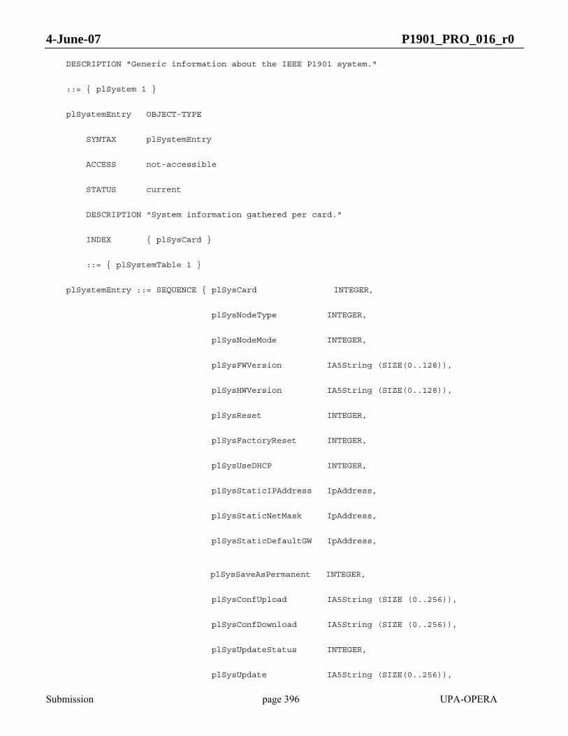
4-June-07 P1901_PRO_016_r0
Submission page 396 UPA-OPERA
DESCRIPTION "Generic information about the IEEE P1901 system."
::= { plSystem 1 }
plSystemEntry OBJECT-TYPE
SYNTAX plSystemEntry
ACCESS not-accessible
STATUS current
DESCRIPTION "System information gathered per card."
INDEX { plSysCard }
::= { plSystemTable 1 }
plSystemEntry ::= SEQUENCE { plSysCard INTEGER,
plSysNodeType INTEGER,
plSysNodeMode INTEGER,
plSysFWVersion IA5String (SIZE(0..128)),
plSysHWVersion IA5String (SIZE(0..128)),
plSysReset INTEGER,
plSysFactoryReset INTEGER,
plSysUseDHCP INTEGER,
plSysStaticIPAddress IpAddress,
plSysStaticNetMask IpAddress,
plSysStaticDefaultGW IpAddress,
plSysSaveAsPermanent INTEGER,
plSysConfUpload IA5String (SIZE (0..256)),
plSysConfDownload IA5String (SIZE (0..256)),
plSysUpdateStatus INTEGER,
plSysUpdate IA5String (SIZE(0..256)),
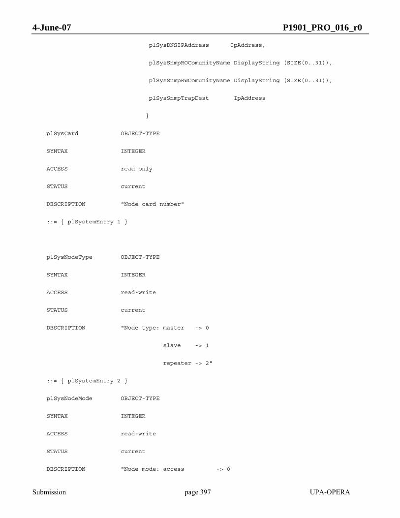
4-June-07 P1901_PRO_016_r0
Submission page 397 UPA-OPERA
plSysDNSIPAddress IpAddress,
plSysSnmpROComunityName DisplayString (SIZE(0..31)),
plSysSnmpRWComunityName DisplayString (SIZE(0..31)),
plSysSnmpTrapDest IpAddress
}
plSysCard OBJECT-TYPE
SYNTAX INTEGER
ACCESS read-only
STATUS current
DESCRIPTION "Node card number"
::= { plSystemEntry 1 }
plSysNodeType OBJECT-TYPE
SYNTAX INTEGER
ACCESS read-write
STATUS current
DESCRIPTION "Node type: master -> 0
slave -> 1
repeater -> 2"
::= { plSystemEntry 2 }
plSysNodeMode OBJECT-TYPE
SYNTAX INTEGER
ACCESS read-write
STATUS current
DESCRIPTION "Node mode: access -> 0

4-June-07 P1901_PRO_016_r0
Submission page 398 UPA-OPERA
in-home -> 1
medium-voltage -> 2"
::= { plSystemEntry 3 }
plSysFWVersion OBJECT-TYPE
SYNTAX IA5String (SIZE(0..128))
ACCESS read-only
STATUS current
DESCRIPTION "Firmware version"
::= { plSystemEntry 5 }
plSysHWVersion OBJECT-TYPE
SYNTAX IA5String (SIZE(0..128))
ACCESS read-only
STATUS current
DESCRIPTION "Hardware version"
::= { plSystemEntry 6 }
plSysReset OBJECT-TYPE
SYNTAX INTEGER
ACCESS read-write
STATUS current
DESCRIPTION "System reset"
::= { plSystemEntry 7 }
plSysFactoryReset OBJECT-TYPE
SYNTAX INTEGER
4-June-07 P1901_PRO_016_r0
Submission page 399 UPA-OPERA
ACCESS read-write
STATUS current
DESCRIPTION "Restore factory parameters"
::= { plSystemEntry 8 }
plSysUseDHCP OBJECT-TYPE
SYNTAX INTEGER
ACCESS read-write
STATUS current
DESCRIPTION "Use DHCP (1) or a fixed IP, netmask and gateway (0) instead"
::= { plSystemEntry 9 }
plSysStaticIPAddress OBJECT-TYPE
SYNTAX IpAddress
ACCESS read-write
STATUS current
DESCRIPTION "Default IP address if DHCP is disabled"
::= { plSystemEntry 10 }
plSysStaticNetMask OBJECT-TYPE
SYNTAX IpAddress
ACCESS read-write
STATUS current
DESCRIPTION "Default netmask if DHCP is disabled"
::= { plSystemEntry 11 }
plSysStaticDefaultGW OBJECT-TYPE
SYNTAX IpAddress
ACCESS read-write

4-June-07 P1901_PRO_016_r0
Submission page 400 UPA-OPERA
STATUS current
DESCRIPTION "Default gateway if DHCP is disabled"
::= { plSystemEntry 12 }
plSysSaveAsPermanent OBJECT-TYPE
SYNTAX INTEGER
ACCESS read-write
STATUS current
DESCRIPTION "Saves changed objects as permanent"
::= { plSystemEntry 14 }
plSysConfUpload OBJECT-TYPE
SYNTAX IA5String (SIZE(0..256))
ACCESS read-write
STATUS current
DESCRIPTION "Uploads node local configuration to a server"
::= { plSystemEntry 15 }
plSysConfDownload OBJECT-TYPE
SYNTAX IA5String (SIZE(0..256))
ACCESS read-write
STATUS current
DESCRIPTION "Forces a configuration file download"
::= { plSystemEntry 16 }
plSysUpgradeStatus OBJECT-TYPE

4-June-07 P1901_PRO_016_r0
Submission page 401 UPA-OPERA
SYNTAX INTEGER
ACCESS read-only
STATUS current
DESCRIPTION "Status of the current upgrade: finished KO -> 0
finished OK -> 1
busy (in progress) -> 2"
::= { plSystemEntry 19 }
plSysUpdate OBJECT-TYPE
SYNTAX IA5String (SIZE(0..256))
ACCESS read-write
STATUS current
DESCRIPTION "Updates the selected flash section of a modem"
::= { plSystemEntry 30 }
plSysDNSIPAddress OBJECT-TYPE
SYNTAX IpAddress
ACCESS read-write
STATUS current
DESCRIPTION "IP address of the DNS"
::= { plSystemEntry 31 }
plSysSnmpROComunityName OBJECT-TYPE
SYNTAX DisplayString (SIZE(0..31))
ACCESS read-write
STATUS current
DESCRIPTION "Community Name string”

4-June-07 P1901_PRO_016_r0
Submission page 402 UPA-OPERA
::= { plSystemEntry 32 }
plSysSnmpRWComunityName OBJECT-TYPE
SYNTAX DisplayString (SIZE(0..31))
ACCESS read-write
STATUS current
DESCRIPTION "Community Name string”
::= { plSystemEntry 33 }
plSysSnmpTrapDest OBJECT-TYPE
SYNTAX IpAddress
ACCESS read-only
STATUS current
DESCRIPTION "Trap destination IP address”
::= { plSystemEntry 34 }
--
-- The plBasic Group
--
plBasicTable OBJECT-TYPE
SYNTAX SEQUENCE OF plBasicEntry
ACCESS not-accessible
STATUS current
DESCRIPTION ""
::= { plBasic 1 }

4-June-07 P1901_PRO_016_r0
Submission page 403 UPA-OPERA
plBasicEntry OBJECT-TYPE
SYNTAX plBasicEntry
ACCESS not-accessible
STATUS current
DESCRIPTION ""
INDEX { plBasicCard }
::= { plBasicTable 1 }
plBasicEntry ::= SEQUENCE { plBasicCard INTEGER,
plBasicMode INTEGER,
plBasicCentralFrequency INTEGER,
plBasicBandwidth INTEGER,
plBasicSearchModes IA5String,
plBasicTXAGCEnable INTEGER,
plBasicRXAGCEnable INTEGER,
plBasicTXAGCGain INTEGER,
plBasicRXAGCGain INTEGER,
plBasicTXPowerMaskLB OCTET STRING (SIZE(769)),
plBasicTXPowerMaskHB OCTET STRING (SIZE(769)),
plBasicMasterMAC PhysAddress
}
plBasicCard OBJECT-TYPE
SYNTAX INTEGER
ACCESS read-only
STATUS current

4-June-07 P1901_PRO_016_r0
Submission page 404 UPA-OPERA
DESCRIPTION "Node card number"
::= { plBasicEntry 1 }
plBasicMode OBJECT-TYPE
SYNTAX INTEGER
ACCESS read-write
STATUS current
DESCRIPTION "Physical mode (1..M)"
::= { plBasicEntry 2 }
plBasicCentralFrequency OBJECT-TYPE
SYNTAX INTEGER
ACCESS read-write
STATUS current
DESCRIPTION "Band Central Frequency in MHz"
::= { plBasicEntry 3 }
plBasicBandwidth OBJECT-TYPE
SYNTAX INTEGER
ACCESS read-write
STATUS current
DESCRIPTION "Working Node Bandwidth in MHz"
::= { plBasicEntry 4 }
plBasicSearchModes OBJECT-TYPE
SYNTAX IA5String
ACCESS read-write

4-June-07 P1901_PRO_016_r0
Submission page 405 UPA-OPERA
STATUS current
DESCRIPTION "List of modes used for searching"
::= { plBasicEntry 5 }
plBasicTXAGCEnable OBJECT-TYPE
SYNTAX INTEGER
ACCESS read-write
STATUS current
DESCRIPTION "TX AGC: Enabled -> 1
Disabled -> 0"
::= { plBasicEntry 6 }
plBasicRXAGCEnable OBJECT-TYPE
SYNTAX INTEGER
ACCESS read-write
STATUS current
DESCRIPTION "RX AGC: Enabled -> 1
Disabled -> 0"
::= { plBasicEntry 7 }
plBasicTXAGCGain OBJECT-TYPE
SYNTAX INTEGER
ACCESS read-write
STATUS current
DESCRIPTION "TX AGC Gain"
::= { plBasicEntry 8 }
4-June-07 P1901_PRO_016_r0
Submission page 406 UPA-OPERA
plBasicRXAGCGain OBJECT-TYPE
SYNTAX INTEGER
ACCESS read-write
STATUS current
DESCRIPTION "RX AGC Gain"
::= { plBasicEntry 9 }
plBasicTXPowerMaskLB OBJECT-TYPE
SYNTAX OCTET STRING ( SIZE ( 769 ) )
ACCESS read-write
STATUS current
DESCRIPTION "Low half Powermask"
::= { plBasicEntry 10 }
plBasicTXPowerMaskHB OBJECT-TYPE
SYNTAX OCTET STRING ( SIZE ( 769 ) )
ACCESS read-write
STATUS current
DESCRIPTION "High half Powermask"
::= { plBasicEntry 11 }
plBasicMasterMAC OBJECT-TYPE
SYNTAX PhysAddress
ACCESS read-only

4-June-07 P1901_PRO_016_r0
Submission page 407 UPA-OPERA
STATUS current
DESCRIPTION "MAC address of the master of current node"
::= { plBasicEntry 12 }
--
-- The plPhy Group
--
-- plPhyByMAC Table
plPhyByMACTable OBJECT-TYPE
SYNTAX SEQUENCE OF plPhyByMACEntry
ACCESS not-accessible
STATUS current
DESCRIPTION "Physical parameters"
::= { plPhy 1 }
plPhyByMACEntry OBJECT-TYPE
SYNTAX plPhyByMACEntry
ACCESS not-accessible
STATUS current
DESCRIPTION ""
INDEX { plPhyByMACCard, plPhyByMACMAC }
::= { plPhyByMACTable 1 }
plPhyByMACEntry ::= SEQUENCE { plPhyByMACCard INTEGER,
plPhyByMACMAC PhysAddress,
plPhyByMACTXBPC OCTET STRING (SIZE(769)),
plPhyByMACTXBPCAggregated INTEGER,
4-June-07 P1901_PRO_016_r0
Submission page 408 UPA-OPERA
plPhyByMACRXBPC OCTET STRING (SIZE(769)),
plPhyByMACRXBPCAggregated INTEGER,
plPhyByMACRXSNR OCTET STRING (SIZE(769)),
plPhyByMACRXCFR OCTET STRING (SIZE(769)),
plPhyByMACTXPhySpeed INTEGER,
plPhyByMACRXPhySpeed INTEGER,
plPhyByMACACK INTEGER,
plPhyByMACCipher INTEGER,
plPhyByMACTXHURTO INTEGER,
plPhyByMACRXHURTO INTEGER,
plPhyByMACIsActive INTEGER,
plPhyByMACRXTimeLastActivity INTEGER
}
plPhyByMACCard OBJECT-TYPE
SYNTAX INTEGER
ACCESS read-only
STATUS current
DESCRIPTION "Node card number"
::= { plPhyByMACEntry 1 }
plPhyByMACMAC OBJECT-TYPE
SYNTAX PhysAddress
ACCESS read-only
STATUS current

4-June-07 P1901_PRO_016_r0
Submission page 409 UPA-OPERA
DESCRIPTION "MAC Address"
::= { plPhyByMACEntry 2 }
plPhyByMACTXBPC OBJECT-TYPE
SYNTAX OCTET STRING ( SIZE ( 769 ) )
ACCESS read-only
STATUS current
DESCRIPTION "BPC in transmission for the low half band"
::= { plPhyByMACEntry 3 }
plPhyByMACTXBPCAggregated OBJECT-TYPE
SYNTAX INTEGER
ACCESS read-only
STATUS current
DESCRIPTION "BPC Aggregated in transmission"
::= { plPhyByMACEntry 5 }
plPhyByMACRXBPC OBJECT-TYPE
SYNTAX OCTET STRING ( SIZE ( 769 ) )
ACCESS read-only
STATUS current
DESCRIPTION "BPC in reception for the low half band"
::= { plPhyByMACEntry 6 }
plPhyByMACRXBPCAggregated OBJECT-TYPE

4-June-07 P1901_PRO_016_r0
Submission page 410 UPA-OPERA
SYNTAX INTEGER
ACCESS read-only
STATUS current
DESCRIPTION "BPC Aggregated in reception"
::= { plPhyByMACEntry 8 }
plPhyByMACRXSNR OBJECT-TYPE
SYNTAX OCTET STRING ( SIZE ( 769 ) )
ACCESS read-only
STATUS current
DESCRIPTION "Measured SNR"
::= { plPhyByMACEntry 9 }
plPhyByMACRXCFR OBJECT-TYPE
SYNTAX OCTET STRING ( SIZE ( 769 ) )
ACCESS read-only
STATUS current
DESCRIPTION "Measured CFR"
::= { plPhyByMACEntry 10 }
plPhyByMACTXPhySpeed OBJECT-TYPE
SYNTAX INTEGER
ACCESS read-only
STATUS current
DESCRIPTION "Physical speed in transmission"
::= { plPhyByMACEntry 11 }
4-June-07 P1901_PRO_016_r0
Submission page 411 UPA-OPERA
plPhyByMACRXPhySpeed OBJECT-TYPE
SYNTAX INTEGER
ACCESS read-only
STATUS current
DESCRIPTION "Physical speed in reception"
::= { plPhyByMACEntry 12 }
plPhyByMACACK OBJECT-TYPE
SYNTAX INTEGER
ACCESS read-write
STATUS current
DESCRIPTION "ACK enabled"
::= { plPhyByMACEntry 13 }
plPhyByMACCipher OBJECT-TYPE
SYNTAX INTEGER
ACCESS read-write
STATUS current
DESCRIPTION "Cipher enabled"
::= { plPhyByMACEntry 14 }
plPhyByMACTXHURTO OBJECT-TYPE
SYNTAX INTEGER
ACCESS read-write
STATUS current
DESCRIPTION "HURTO mode in transmission"
::= { plPhyByMACEntry 15 }
4-June-07 P1901_PRO_016_r0
Submission page 412 UPA-OPERA
plPhyByMACRXHURTO OBJECT-TYPE
SYNTAX INTEGER
ACCESS read-write
STATUS current
DESCRIPTION "HURTO mode in reception"
::= { plPhyByMACEntry 16 }
plPhyByMACIsActive OBJECT-TYPE
SYNTAX INTEGER
ACCESS read-only
STATUS current
DESCRIPTION "Checks if the node is active or not"
::= { plPhyByMACEntry 17 }
plPhyByMACRXTimeLastActivity OBJECT-TYPE
SYNTAX INTEGER
ACCESS read-only
STATUS current
DESCRIPTION "Time since last BPL activity"
::= { plPhyByMACEntry 18 }
-- plPhyRXSNRThreshold Table
plPhyRXSNRThresholdTable OBJECT-TYPE
SYNTAX SEQUENCE OF plPhyRXSNRThresholdEntry
ACCESS not-accessible
STATUS current
DESCRIPTION ""
4-June-07 P1901_PRO_016_r0
Submission page 413 UPA-OPERA
::= { plWiscPhy 2 }
plPhyRXSNRThresholdEntry OBJECT-TYPE
SYNTAX plPhyRXSNRThresholdEntry
ACCESS not-accessible
STATUS current
DESCRIPTION ""
INDEX { plPhyRXSNRThresholdCard, plPhyRXSNRThresholdIndex }
::= { plPhyRXSNRThresholdTable 1 }
plPhyRXSNRThresholdEntry ::= SEQUENCE { plPhyRXSNRThresholdCard INTEGER,
plPhyRXSNRThresholdIndex INTEGER,
plPhyRXSNRThreshold INTEGER
}
plPhyRXSNRThresholdCard OBJECT-TYPE
SYNTAX INTEGER
ACCESS not-accessible
STATUS current
DESCRIPTION "Node card number"
::= { plPhyRXSNRThresholdEntry 1 }
plPhyRXSNRThresholdIndex OBJECT-TYPE
SYNTAX INTEGER
ACCESS not-accessible
STATUS current
DESCRIPTION "SNR threshold value index (1..10)"

4-June-07 P1901_PRO_016_r0
Submission page 414 UPA-OPERA
::= { plPhyRXSNRThresholdEntry 2 }
plPhyRXSNRThreshold OBJECT-TYPE
SYNTAX INTEGER
ACCESS read-write
STATUS current
DESCRIPTION "SNR threshold value"
::= { plPhyRXSNRThresholdEntry 3 }
--
-- The plMAC Group
--
-- plMAC Table
plMACTable OBJECT-TYPE
SYNTAX SEQUENCE OF plMACEntry
ACCESS not-accessible
STATUS current
DESCRIPTION ""
::= { plMAC 1 }
plMACEntry OBJECT-TYPE
SYNTAX plMACEntry
ACCESS not-accessible
STATUS current
DESCRIPTION ""
INDEX { plMACCard }

4-June-07 P1901_PRO_016_r0
Submission page 415 UPA-OPERA
::= { plMACTable 1 }
plMACEntry ::= SEQUENCE { plMACCard INTEGER,
plMACAccessProtocol INTEGER,
plMACNumConnectedNodes INTEGER,
plMACNumSlaves INTEGER
}
plMACCard OBJECT-TYPE
SYNTAX INTEGER
ACCESS read-only
STATUS current
DESCRIPTION "Node card number"
::= { plMACEntry 1 }
plMACAccessProtocol OBJECT-TYPE
SYNTAX INTEGER
ACCESS read-write
STATUS current
DESCRIPTION "Autodiscovery mode enabled"
::= { plMACEntry 2 }
plMACNumConnectedNodes OBJECT-TYPE
SYNTAX INTEGER
ACCESS read-only
STATUS current
DESCRIPTION "Number of nodes with link solved (PSP)"

4-June-07 P1901_PRO_016_r0
Submission page 416 UPA-OPERA
::= { plMACEntry 3 }
plMACNumSlaves OBJECT-TYPE
SYNTAX INTEGER
ACCESS read-only
STATUS current
DESCRIPTION "Number of slaves configured in the master or repeater"
::= { plMACEntry 4 }
-- plMACConnectedNodes Table
plMACConnectedNodesTable OBJECT-TYPE
SYNTAX SEQUENCE OF plMACConnectedNodesEntry
ACCESS not-accessible
STATUS current
DESCRIPTION ""
::= { plWiscMAC 2 }
plMACConnectedNodesEntry OBJECT-TYPE
SYNTAX plMACConnectedNodesEntry
ACCESS not-accessible
STATUS current
DESCRIPTION ""
INDEX { plMACConnectedNodesCard, plMACConnectedNodesIndex }
::= { plMACConnectedNodesTable 1 }
plMACConnectedNodesEntry ::= SEQUENCE { plMACConnectedNodesCard INTEGER,
plMACConnectedNodesIndex INTEGER,
plMACConnectedNodesMAC PhysAddress

4-June-07 P1901_PRO_016_r0
Submission page 417 UPA-OPERA
}
plMACConnectedNodesCard OBJECT-TYPE
SYNTAX INTEGER
ACCESS read-only
STATUS current
DESCRIPTION "Node card number"
::= { plMACConnectedNodesEntry 1 }
plMACConnectedNodesIndex OBJECT-TYPE
SYNTAX INTEGER
ACCESS read-only
STATUS current
DESCRIPTION "Node index"
::= {plMACConnectedNodesEntry 2}
plMACConnectedNodesMAC OBJECT-TYPE
SYNTAX PhysAddress
ACCESS read-only
STATUS current
DESCRIPTION "MAC for the node index"
::= {plMACConnectedNodesEntry 3}
-- plMACSlaves Table
plMACSlavesTable OBJECT-TYPE
SYNTAX SEQUENCE OF plMACSlavesEntry

4-June-07 P1901_PRO_016_r0
Submission page 418 UPA-OPERA
ACCESS not-accessible
STATUS current
DESCRIPTION ""
::= { plWiscMAC 3 }
plMACSlavesEntry OBJECT-TYPE
SYNTAX plMACSlavesEntry
ACCESS not-accessible
STATUS current
DESCRIPTION ""
INDEX { plMACSlavesCard, plMACSlavesIndex }
::= { plMACSlavesTable 1 }
plMACSlavesEntry ::= SEQUENCE { plMACSlavesCard INTEGER,
plMACSlavesIndex INTEGER,
plMACSlavesMAC PhysAddress
}
plMACSlavesCard OBJECT-TYPE
SYNTAX INTEGER
ACCESS read-only
STATUS current
DESCRIPTION "Node card number"
::= { plMACSlavesEntry 1 }
plMACSlavesIndex OBJECT-TYPE
SYNTAX INTEGER

4-June-07 P1901_PRO_016_r0
Submission page 419 UPA-OPERA
ACCESS read-only
STATUS current
DESCRIPTION "Slaves index"
::= { plMACSlavesEntry 2 }
plMACSlavesMAC OBJECT-TYPE
SYNTAX PhysAddress
ACCESS read-only
STATUS current
DESCRIPTION "MAC for the slave index"
::= { plMACSlavesEntry 3 }
--
-- The plQoS Group
--
plQoSMasterGeneralMinOneWayLat OBJECT-TYPE
SYNTAX INTEGER
ACCESS read-only
STATUS current
DESCRIPTION "Latency in milliseconds"
::= { plQoS 1 }
plQoSMasterGeneralBwMngrPolicy OBJECT-TYPE
SYNTAX INTEGER
ACCESS read-only
STATUS current

4-June-07 P1901_PRO_016_r0
Submission page 420 UPA-OPERA
DESCRIPTION "Bandwidth ..."
::= { plQoS 2 }
-- plQoSPriorityManagement Table
plQoSPriorityManagementTable OBJECT-TYPE
SYNTAX SEQUENCE OF plQoSPriorityManagementEntry
ACCESS not-accessible
STATUS current
DESCRIPTION ""
::= { plQoS 3 }
plQoSPriorityManagementEntry OBJECT-TYPE
SYNTAX plQoSPriorityManagementEntry
ACCESS not-accessible
STATUS current
DESCRIPTION "QoS Priorities Management per card."
INDEX { plQoSPriorityManagementCard, plQoSPriorityManagementPrio }
::= { plQoSPriorityManagementTable 1 }
plQoSPriorityManagementEntry ::= SEQUENCE {
plQoSPriorityManagementCard INTEGER,
plQoSPriorityManagementPrio INTEGER,
plQoSPriorityManagementLatency INTEGER,
plQoSPriorityManagementJitter INTEGER,
plQoSPriorityManagementBandwidth INTEGER

4-June-07 P1901_PRO_016_r0
Submission page 421 UPA-OPERA
}
plQoSPriorityManagementCard OBJECT-TYPE
SYNTAX INTEGER
ACCESS read-only
STATUS current
DESCRIPTION "Node card number"
::= { plQoSPriorityManagementEntry 1 }
plQoSPriorityManagementPrio OBJECT-TYPE
SYNTAX INTEGER
ACCESS read-write
STATUS current
DESCRIPTION "Priority value (1..8)"
::= { plQoSPriorityManagementEntry 2 }
plQoSPriorityManagementLatency OBJECT-TYPE
SYNTAX INTEGER
ACCESS read-only
STATUS current
DESCRIPTION "Latency value for the priority (0,1,2,4,8)"
::= { plQoSPriorityManagementEntry 3 }
plQoSPriorityManagementJitter OBJECT-TYPE
SYNTAX INTEGER
ACCESS read-only
STATUS current
DESCRIPTION "Jitter value for the priority"
::= { plQoSPriorityManagementEntry 4 }

4-June-07 P1901_PRO_016_r0
Submission page 422 UPA-OPERA
plQoSPriorityManagementBandwidth OBJECT-TYPE
SYNTAX INTEGER
ACCESS read-only
STATUS current
DESCRIPTION "Bandwidth for the priority"
::= { plQoSPriorityManagementEntry 5 }
-- plQoSPerUser Table
plQoSPerUserTable OBJECT-TYPE
SYNTAX SEQUENCE OF plQoSPerUserEntry
ACCESS not-accessible
STATUS current
DESCRIPTION ""
::= { plWiscQoS 4 }
plQoSPerUserEntry OBJECT-TYPE
SYNTAX plQoSPerUserEntry
ACCESS not-accessible
STATUS current
DESCRIPTION "User QoS management values per card."
INDEX { plQoSPerUserCard, plQoSPerUserMAC }
::= { plQoSPerUserTable 1 }
plQoSPerUserEntry ::= SEQUENCE { plQoSPerUserCard INTEGER,
plQoSPerUserMAC PhysAddress,
plQoSPerUserTXMaxXput INTEGER,
4-June-07 P1901_PRO_016_r0
Submission page 423 UPA-OPERA
plQoSPerUserRXMaxXput INTEGER,
plQoSPerUserPriorityAllowedUp INTEGER,
plQoSPerUserPriorityAllowedDown INTEGER
-- plQoSPerUserPriorityActive INTEGER
}
plQoSPerUserCard OBJECT-TYPE
SYNTAX INTEGER
ACCESS read-only
STATUS current
DESCRIPTION "Node card number"
::= { plQoSPerUserEntry 1 }
plQoSPerUserMAC OBJECT-TYPE
SYNTAX PhysAddress
ACCESS read-only
STATUS current
DESCRIPTION "User MAC address"
::= { plQoSPerUserEntry 2 }
plQoSPerUserTXMaxXput OBJECT-TYPE
SYNTAX INTEGER
ACCESS read-only
STATUS current
DESCRIPTION "Maximum allowed throughput in transmission for a user"
::= { plQoSPerUserEntry 3 }
plQoSPerUserRXMaxXput OBJECT-TYPE
SYNTAX INTEGER

4-June-07 P1901_PRO_016_r0
Submission page 424 UPA-OPERA
ACCESS read-only
STATUS current
DESCRIPTION "Maximum allowed throughput in reception for a user"
::= { plQoSPerUserEntry 4 }
plQoSPerUserPriorityAllowedUp OBJECT-TYPE
SYNTAX INTEGER
ACCESS read-only
STATUS current
DESCRIPTION "Allowed priorities for transmission and reception in upstream for a user"
::= { plQoSPerUserEntry 5 }
plQoSPerUserPriorityAllowedDown OBJECT-TYPE
SYNTAX INTEGER
ACCESS read-only
STATUS current
DESCRIPTION "Allowed priorities for transmission and reception in downstream for a user"
::= { plQoSPerUserEntry 6 }
-- plQoSPerUserPriorityActive OBJECT-TYPE
-- SYNTAX INTEGER
-- ACCESS read-only
-- STATUS current
-- DESCRIPTION "Active priorities for transmission and reception for a user"
-- ::= { plQoSPerUserEntry 7 }
--

4-June-07 P1901_PRO_016_r0
Submission page 425 UPA-OPERA
-- The plStatistics Group
--
-- plStatistics Table
plStatisticsTable OBJECT-TYPE
SYNTAX SEQUENCE OF plStatisticsEntry
ACCESS not-accessible
STATUS current
DESCRIPTION "Packets and Bytes Statistics by Interface"
::= { plStatistics 1 }
plStatisticsEntry OBJECT-TYPE
SYNTAX plStatisticsEntry
ACCESS not-accessible
STATUS current
DESCRIPTION ""
INDEX { plStatisticsCard }
::= { plStatisticsTable 1 }
plStatisticsEntry ::= SEQUENCE {
plStatisticsCard INTEGER,
plStatisticsBPLInputWords INTEGER,
plStatisticsBPLInputPackets INTEGER,
plStatisticsBPLInputIncorrigible INTEGER,
plStatisticsBPLInputFECBlocksTotal INTEGER,
plStatisticsBPLInputFECBlocksCorrected INTEGER,

4-June-07 P1901_PRO_016_r0
Submission page 426 UPA-OPERA
plStatisticsBPLInputPktsReceived INTEGER,
plStatisticsBPLInputPktsRcvComplete INTEGER,
plStatisticsBPLInputPktsRcvIncomplete INTEGER,
plStatisticsBPLOutputWords INTEGER,
plStatisticsBPLOutputPkts INTEGER
}
plStatisticsCard OBJECT-TYPE
SYNTAX INTEGER
ACCESS read-only
STATUS current
DESCRIPTION "Node card number"
::= { plStatisticsEntry 1 }
plStatisticsBPLInputWords OBJECT-TYPE
SYNTAX INTEGER
ACCESS read-only
STATUS current
DESCRIPTION "Words received by BPL"
::= { plStatisticsEntry 19 }
plStatisticsBPLInputPackets OBJECT-TYPE
SYNTAX INTEGER
ACCESS read-only
STATUS current
DESCRIPTION "Packets received by BPL"
::= { plStatisticsEntry 20 }

4-June-07 P1901_PRO_016_r0
Submission page 427 UPA-OPERA
plStatisticsBPLInputIncorrigible OBJECT-TYPE
SYNTAX INTEGER
ACCESS read-only
STATUS current
DESCRIPTION "Incorrigible packets received by BPL"
::= { plStatisticsEntry 21 }
plStatisticsBPLInputFECBlocksTotal OBJECT-TYPE
SYNTAX INTEGER
ACCESS read-only
STATUS current
DESCRIPTION "Received FEC blocks by BPL"
::= { plStatisticsEntry 22 }
plStatisticsBPLInputFECBlocksCorrected OBJECT-TYPE
SYNTAX INTEGER
ACCESS read-only
STATUS current
DESCRIPTION "FEC blocks corrected by BPL"
::= { plStatisticsEntry 23 }
plStatisticsBPLInputPktsReceived OBJECT-TYPE
SYNTAX INTEGER
ACCESS read-only
STATUS current

4-June-07 P1901_PRO_016_r0
Submission page 428 UPA-OPERA
DESCRIPTION "Received packets by BPL"
::= { plStatisticsEntry 24 }
plStatisticsBPLInputPktsRcvComplete OBJECT-TYPE
SYNTAX INTEGER
ACCESS read-only
STATUS current
DESCRIPTION "Complete received packets by BPL"
::= { plStatisticsEntry 25 }
plStatisticsBPLInputPktsRcvIncomplete OBJECT-TYPE
SYNTAX INTEGER
ACCESS read-only
STATUS current
DESCRIPTION "Incomplete received packets by BPL"
::= { plStatisticsEntry 26 }
plStatisticsBPLOutputWords OBJECT-TYPE
SYNTAX INTEGER
ACCESS read-only
STATUS current
DESCRIPTION "Transmitted words by BPL"
::= { plStatisticsEntry 27 }
plStatisticsBPLOutputPkts OBJECT-TYPE
SYNTAX INTEGER
4-June-07 P1901_PRO_016_r0
Submission page 429 UPA-OPERA
ACCESS read-only
STATUS current
DESCRIPTION "Transmitted packets by BPL"
::= { plStatisticsEntry 28 }
-- End of plStatistics Table
--
-- The plTraps Group
--
-- plTrapsPhy Table
plTrapsPhyTable OBJECT-TYPE
SYNTAX SEQUENCE OF plTrapsPhyEntry
ACCESS not-accessible
STATUS current
DESCRIPTION ""
::= { plTraps 1 }
plTrapsPhyEntry OBJECT-TYPE
SYNTAX plTrapsPhyEntry
ACCESS not-accessible
STATUS current
DESCRIPTION ""
INDEX { plTrapsPhyCard }
::= { plPhyTable 1 }
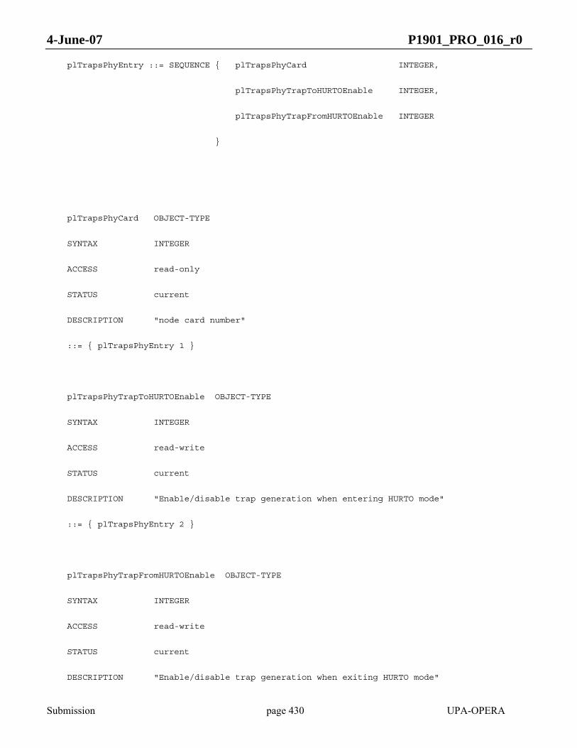
4-June-07 P1901_PRO_016_r0
Submission page 430 UPA-OPERA
plTrapsPhyEntry ::= SEQUENCE { plTrapsPhyCard INTEGER,
plTrapsPhyTrapToHURTOEnable INTEGER,
plTrapsPhyTrapFromHURTOEnable INTEGER
}
plTrapsPhyCard OBJECT-TYPE
SYNTAX INTEGER
ACCESS read-only
STATUS current
DESCRIPTION "node card number"
::= { plTrapsPhyEntry 1 }
plTrapsPhyTrapToHURTOEnable OBJECT-TYPE
SYNTAX INTEGER
ACCESS read-write
STATUS current
DESCRIPTION "Enable/disable trap generation when entering HURTO mode"
::= { plTrapsPhyEntry 2 }
plTrapsPhyTrapFromHURTOEnable OBJECT-TYPE
SYNTAX INTEGER
ACCESS read-write
STATUS current
DESCRIPTION "Enable/disable trap generation when exiting HURTO mode"

4-June-07 P1901_PRO_016_r0
Submission page 431 UPA-OPERA
::= { plTrapsPhyEntry 3 }
-- plTrapsMAC Table
plTrapsMACTable OBJECT-TYPE
SYNTAX SEQUENCE OF plTrapsMACEntry
ACCESS not-accessible
STATUS current
DESCRIPTION ""
::= { plWiscTraps 2 }
plTrapsMACEntry OBJECT-TYPE
SYNTAX plTrapsMACEntry
ACCESS not-accessible
STATUS current
DESCRIPTION ""
INDEX { plTrapsMACCard }
::= { plTrapsMACTable 1 }
plTrapsMACEntry ::= SEQUENCE { plTrapsMACCard INTEGER,
plTrapsMACPeerDetectedEnable INTEGER,
plTrapsMACPeerDisappearedEnable INTEGER
}
plTrapsMACCard OBJECT-TYPE
SYNTAX INTEGER
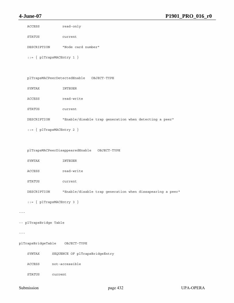
4-June-07 P1901_PRO_016_r0
Submission page 432 UPA-OPERA
ACCESS read-only
STATUS current
DESCRIPTION "Node card number"
::= { plTrapsMACEntry 1 }
plTrapsMACPeerDetectedEnable OBJECT-TYPE
SYNTAX INTEGER
ACCESS read-write
STATUS current
DESCRIPTION "Enable/disable trap generation when detecting a peer"
::= { plTrapsMACEntry 2 }
plTrapsMACPeerDisappearedEnable OBJECT-TYPE
SYNTAX INTEGER
ACCESS read-write
STATUS current
DESCRIPTION "Enable/disable trap generation when dissapearing a peer"
::= { plTrapsMACEntry 3 }
---
-- plTrapsBridge Table
---
plTrapsBridgeTable OBJECT-TYPE
SYNTAX SEQUENCE OF plTrapsBridgeEntry
ACCESS not-accessible
STATUS current

4-June-07 P1901_PRO_016_r0
Submission page 433 UPA-OPERA
DESCRIPTION ""
::= { plWiscTraps 3 }
plTrapsBridgeEntry OBJECT-TYPE
SYNTAX plTrapsBridgeEntry
ACCESS not-accessible
STATUS current
DESCRIPTION ""
INDEX { plTrapsBridgeCard }
::= { plTrapsBridgeTable 1 }
plTrapsBridgeEntry ::= SEQUENCE { plTrapsBridgeCard INTEGER,
plTrapsBridgeNewRootEnable INTEGER,
plTrapsBridgeTopologyChangeEnable INTEGER
}
plTrapsBridgeCard OBJECT-TYPE
SYNTAX INTEGER
ACCESS read-only
STATUS current
DESCRIPTION "Node card number"
::= { plTrapsBridgeEntry 1 }
plTrapsBridgeNewRootEnable OBJECT-TYPE
SYNTAX INTEGER
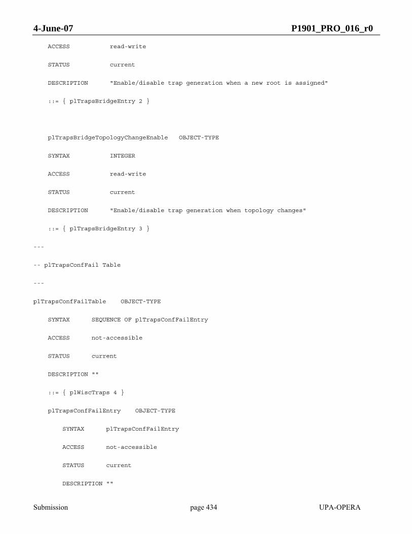
4-June-07 P1901_PRO_016_r0
Submission page 434 UPA-OPERA
ACCESS read-write
STATUS current
DESCRIPTION "Enable/disable trap generation when a new root is assigned"
::= { plTrapsBridgeEntry 2 }
plTrapsBridgeTopologyChangeEnable OBJECT-TYPE
SYNTAX INTEGER
ACCESS read-write
STATUS current
DESCRIPTION "Enable/disable trap generation when topology changes"
::= { plTrapsBridgeEntry 3 }
---
-- plTrapsConfFail Table
---
plTrapsConfFailTable OBJECT-TYPE
SYNTAX SEQUENCE OF plTrapsConfFailEntry
ACCESS not-accessible
STATUS current
DESCRIPTION ""
::= { plWiscTraps 4 }
plTrapsConfFailEntry OBJECT-TYPE
SYNTAX plTrapsConfFailEntry
ACCESS not-accessible
STATUS current
DESCRIPTION ""
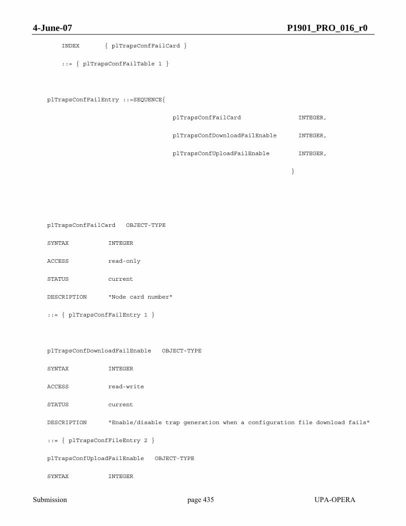
4-June-07 P1901_PRO_016_r0
Submission page 435 UPA-OPERA
INDEX { plTrapsConfFailCard }
::= { plTrapsConfFailTable 1 }
plTrapsConfFailEntry ::=SEQUENCE{
plTrapsConfFailCard INTEGER,
plTrapsConfDownloadFailEnable INTEGER,
plTrapsConfUploadFailEnable INTEGER,
}
plTrapsConfFailCard OBJECT-TYPE
SYNTAX INTEGER
ACCESS read-only
STATUS current
DESCRIPTION "Node card number"
::= { plTrapsConfFailEntry 1 }
plTrapsConfDownloadFailEnable OBJECT-TYPE
SYNTAX INTEGER
ACCESS read-write
STATUS current
DESCRIPTION "Enable/disable trap generation when a configuration file download fails"
::= { plTrapsConfFileEntry 2 }
plTrapsConfUploadFailEnable OBJECT-TYPE
SYNTAX INTEGER

4-June-07 P1901_PRO_016_r0
Submission page 436 UPA-OPERA
ACCESS read-write
STATUS current
DESCRIPTION "Enable/disable trap generation when a configuration file upload fails"
::= { plTrapsConfFileEntry 3 }
--
-- The plStp Group
--
plStpTable OBJECT-TYPE
SYNTAX SEQUENCE OF plStpEntry
ACCESS not-accessible
STATUS current
DESCRIPTION "Information about Spanning Tree."
::= { plWiscStp 1 }
plStpEntry OBJECT-TYPE
SYNTAX plStpEntry
ACCESS not-accessible
STATUS current
DESCRIPTION "System information gathered per card."
INDEX { plStpCard }
::= { plStpTable 1 }
plStpEntry ::= SEQUENCE { plStpCard INTEGER,
plStpEnable INTEGER,
plStpProtocolVersion IA5String (SIZE(0..8)),

4-June-07 P1901_PRO_016_r0
Submission page 437 UPA-OPERA
plStpPtpExtA INTEGER,
plStpPtpExtB INTEGER,
plStpFrontier IA5String (SIZE(0..8))
}
plStpCard OBJECT-TYPE
SYNTAX INTEGER
ACCESS read-only
STATUS current
DESCRIPTION "Node card number"
::= { plStpEntry 1 }
plStpEnable OBJECT-TYPE
SYNTAX INTEGER
ACCESS read-write
STATUS current
DESCRIPTION "0: STP Enabled, 1: STP Disabled"
::= { plStpEntry 2 }
plStpProtocolVersion OBJECT-TYPE
SYNTAX IA5String (SIZE(0..8))
ACCESS read-write
STATUS current
DESCRIPTION "STP Protocol Version [STP|RSTP]"
::= { plStpEntry 3 }
plStpPtpExtA OBJECT-TYPE

4-June-07 P1901_PRO_016_r0
Submission page 438 UPA-OPERA
SYNTAX INTEGER
ACCESS read-write
STATUS current
DESCRIPTION "Set point-to-point flag for EXTA [0|1]"
::= { plStpEntry 4 }
plStpPtpExtB OBJECT-TYPE
SYNTAX INTEGER
ACCESS read-write
STATUS current
DESCRIPTION "Set point-to-point flag for EXTB [0|1]"
::= { plStpEntry 5 }
plStpFrontier OBJECT-TYPE
SYNTAX IA5String (SIZE(0..8))
ACCESS read-write
STATUS current
DESCRIPTION "STP Frontier enabled in [EXTA|EXTB|NONE]"
::= { plStpEntry 6 }
--
-- The plSecurity Group
--
plSecurityConsoleSerial OBJECT-TYPE
SYNTAX INTEGER { enabled ( 1 ),

4-June-07 P1901_PRO_016_r0
Submission page 439 UPA-OPERA
disabled ( 0 ) }
MAX-ACCESS read-write
STATUS current
DESCRIPTION "Enable/disable access to the modems
serial port console."
DEFVAL { enabled }
::= { plSecurity 1 }
plSecurityConsoleTelnet OBJECT-TYPE
SYNTAX INTEGER { enabled ( 1 ),
disabled ( 0 ) }
MAX-ACCESS read-write
STATUS current
DESCRIPTION "Enable/disable access to the modems
telnet console."
DEFVAL { disabled }
::= { plSecurity 2 }
plSecurityConsoleAuthTable OBJECT-TYPE
SYNTAX SEQUENCE OF SecurityConsoleAuthEntry
MAX-ACCESS not-accessible

4-June-07 P1901_PRO_016_r0
Submission page 440 UPA-OPERA
STATUS current
DESCRIPTION "Table of IP addresses form which
Telnet clients may access this modem."
::= { plSecurity 3 }
plSecurityConsoleAuthEntry OBJECT-TYPE
SYNTAX SecurityConsoleAuthEntry
MAX-ACCESS not-accessible
STATUS current
DESCRIPTION "One entry of the table."
INDEX { securityConsoleAuthNumber }
::= { plSecurityConsoleAuthTable 1 }
plSecurityConsoleAuthEntry ::= SEQUENCE {
plSecurityConsoleAuthNumber INTEGER,
plSecurityConsoleAuthAddress IpAddress,
plSecurityConsoleAuthRowStatus RowStatus
}
plSecurityConsoleAuthNumber OBJECT-TYPE
SYNTAX INTEGER (0..15)
MAX-ACCESS not-accessible

4-June-07 P1901_PRO_016_r0
Submission page 441 UPA-OPERA
STATUS current
DESCRIPTION "Number of this row."
::= { plSecurityConsoleAuthEntry 1 }
plSecurityConsoleAuthAddress OBJECT-TYPE
SYNTAX IpAddress
MAX-ACCESS read-create
STATUS current
DESCRIPTION "IP address of client."
::= { plSecurityConsoleAuthEntry 2 }
plSecurityConsoleAuthRowStatus OBJECT-TYPE
SYNTAX RowStatus
MAX-ACCESS read-create
STATUS current
DESCRIPTION "The status of this conceptual row."
::= { plSecurityConsoleAuthEntry 3 }
END
4-June-07 P1901_PRO_016_r0
Submission page 442 UPA-OPERA
ANNEX B PERFORMANCE (INFORMATIVE)
The total bitrate transmitted by a BPL node is influenced by several factors. Considering PHY level, the maximum theoretical rates depend on the OFDM Symbol Type and spectral efficiency, which is bound by the bit-loading of each subcarrier.
Approximate numerical values will be given for maximum bit rates, taking into account these factors:
• OFDM symbol rate and cyclic prefix
• Truncated 4D-TCM
• Loss rate due to RS coding
• CRC overhead (Delimiters)
And specifically not considering these:
• Zero filling
• Special coding of last Reed-Solomon codewords
• Overhead of reference signals when fitting OFDM symbols inside PPDU.
For simplicity purposes, numerical values will only be given for the special cases in which all 1536 subcarriers have the same bit-loading. This makes calculations easier, but it should not be difficult to find corresponding numerical values for any possible bit-loading table.
B.1 Data stream
Data payload is adaptively or HURTO modulated.
The cyclic prefix that each Symbol Type uses implies that actual data is only transmitted during the IDFT interval. The percentage of maximum PHY rate that is lost equals the percentage of cyclic prefix interval over total symbol interval (which is the sum of cyclic prefix and IDFT interval). The IDFT interval is fixed to 2048 samples for every Symbol Type.
Truncated 4D-TCM operates on 768 pairs of subcarriers.
For adaptive mapping, each pair of subcarriers gets a different coding according to its bit-loading: if we call z to
the sum of the bit-loadings of both subcarriers, the coding rate for that pair of subcarriers is z
z 1−, except for the
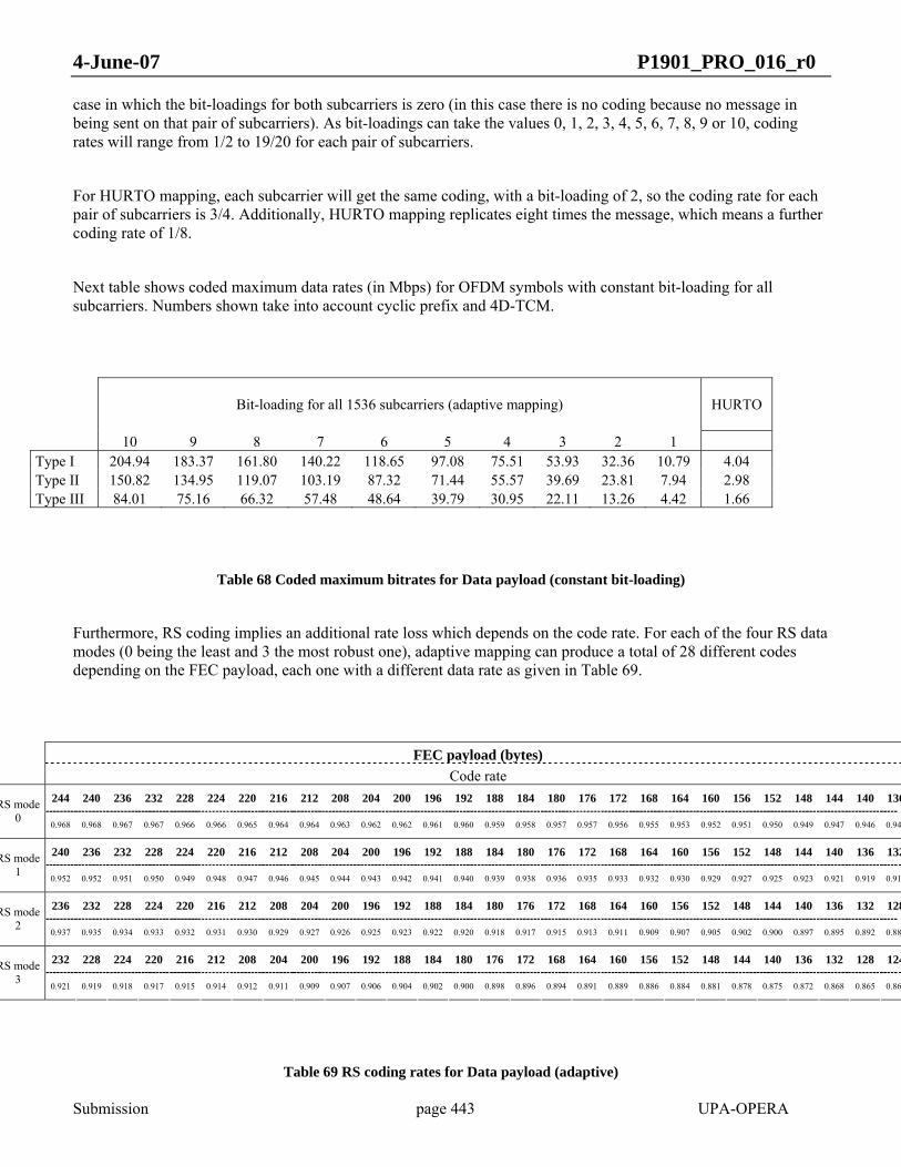
4-June-07 P1901_PRO_016_r0
Submission page 443 UPA-OPERA
case in which the bit-loadings for both subcarriers is zero (in this case there is no coding because no message in being sent on that pair of subcarriers). As bit-loadings can take the values 0, 1, 2, 3, 4, 5, 6, 7, 8, 9 or 10, coding rates will range from 1/2 to 19/20 for each pair of subcarriers.
For HURTO mapping, each subcarrier will get the same coding, with a bit-loading of 2, so the coding rate for each pair of subcarriers is 3/4. Additionally, HURTO mapping replicates eight times the message, which means a further coding rate of 1/8.
Next table shows coded maximum data rates (in Mbps) for OFDM symbols with constant bit-loading for all subcarriers. Numbers shown take into account cyclic prefix and 4D-TCM.
Bit-loading for all 1536 subcarriers (adaptive mapping) HURTO
10 9 8 7 6 5 4 3 2 1 Type I 204.94 183.37 161.80 140.22 118.65 97.08 75.51 53.93 32.36 10.79 4.04 Type II 150.82 134.95 119.07 103.19 87.32 71.44 55.57 39.69 23.81 7.94 2.98 Type III 84.01 75.16 66.32 57.48 48.64 39.79 30.95 22.11 13.26 4.42 1.66
Table 68 Coded maximum bitrates for Data payload (constant bit-loading)
Furthermore, RS coding implies an additional rate loss which depends on the code rate. For each of the four RS data modes (0 being the least and 3 the most robust one), adaptive mapping can produce a total of 28 different codes depending on the FEC payload, each one with a different data rate as given in Table 69.
FEC payload (bytes)
Code rate 244 240 236 232 228 224 220 216 212 208 204 200 196 192 188 184 180 176 172 168 164 160 156 152 148 144 140 136RS mode
0 0.968 0.968 0.967 0.967 0.966 0.966 0.965 0.964 0.964 0.963 0.962 0.962 0.961 0.960 0.959 0.958 0.957 0.957 0.956 0.955 0.953 0.952 0.951 0.950 0.949 0.947 0.946 0.944
240 236 232 228 224 220 216 212 208 204 200 196 192 188 184 180 176 172 168 164 160 156 152 148 144 140 136 132RS mode 1
0.952 0.952 0.951 0.950 0.949 0.948 0.947 0.946 0.945 0.944 0.943 0.942 0.941 0.940 0.939 0.938 0.936 0.935 0.933 0.932 0.930 0.929 0.927 0.925 0.923 0.921 0.919 0.917
236 232 228 224 220 216 212 208 204 200 196 192 188 184 180 176 172 168 164 160 156 152 148 144 140 136 132 128RS mode 2
0.937 0.935 0.934 0.933 0.932 0.931 0.930 0.929 0.927 0.926 0.925 0.923 0.922 0.920 0.918 0.917 0.915 0.913 0.911 0.909 0.907 0.905 0.902 0.900 0.897 0.895 0.892 0.889
232 228 224 220 216 212 208 204 200 196 192 188 184 180 176 172 168 164 160 156 152 148 144 140 136 132 128 124RS mode 3
0.921 0.919 0.918 0.917 0.915 0.914 0.912 0.911 0.909 0.907 0.906 0.904 0.902 0.900 0.898 0.896 0.894 0.891 0.889 0.886 0.884 0.881 0.878 0.875 0.872 0.868 0.865 0.86
Table 69 RS coding rates for Data payload (adaptive)

4-June-07 P1901_PRO_016_r0
Submission page 444 UPA-OPERA
HURTO mapping can use all the RS codes above plus codes with decreasing FEC payload until code rate is 0.5.
The uncoded maximum bitrates for Data payload are the result of multiplying coded maximum bitrates by RS coding rate.
B.2 Delimiters
Delimiters are HURTO modulated for robust OFDM transmission.
Control symbols have modulation and trellis coding schemes similar to HURTO data symbols, so the maximum coded data rate is the same.
Delimiters use a specific RS code with rate 2/3. Additionally, a CRC-CCITT is applied which implies a rate loss of 176/192.
So in the same conditions as assumed for Data payload, the Delimiters data rate is given in Table 70
Uncoded bitrate (Mbps)
Type I 2.47 Type II 1.82 Type III 1.01
Table 70 Coded maximum bitrates for Delimiters

Work Package: WP5
Type of document: Report
Date: 04 June 2007
EC/IST FP6 Project No 026920 File name: OP2_WP5_D27 Version: 1.0
Title: First draft of the OPERA specification version 2
Copyright “Copyright and Reprint Permissions. You may freely reproduce all or part of this paper for non-commercial purposes, provided that the following conditions are fulfilled: (i) to cite the authors, as the copyright owners (ii) to cite the OPERA Project and mention that the European Commission co-finances it, by means of including this statement “OPERA. IST Integrated Project No 507667. Funded by EC” and (iii) not to alter the information.”