first draft (6 august, 1997): status of muon colliders and ... · first draft (6 august, 1997):...
TRANSCRIPT

First Draft (6 August, 1997): Status of Muon Colliders and Future Research andDevelopment Plans
The Muon Collider Collaboration
MUON COLLIDER COLLABORATION:
Charles M. Ankenbrandt1, M. Atac 1, Giorgio Apollinari2,Bruno Autin2, Valerie I. Balbekov1, Vernon D. Barger3,Odette Benary4, Michael S. Berger5, S. Alex Bogacz6,Shlomo Caspi7, Christine Celata7, Yong-Chul Chae8, Wen-Hao Cheng7, David B. Cline9, John Corlett7, H. ThomasDiehl1, Alexandr Drozhdin1, Richard C. Fernow10, Miguel A.Furman7, Juan C. Gallardo10, Alper A. Garren7, Stephen H.
Geer1, Michael A. Green7, John F. Gunion11, Tao Han11, AdyHershcovitch10, Colin Johnson2, Carol Johnstone1, StephenA. Kahn10, Bruce J. King10, Harold G. Kirk10, MasayukiuKumada12, Paul LeBrun1, Kevin Lee9, Derun Li7, DavidLissauer10, Chang-guo Lu13, Luccio10 Kirk T. McDonald13,Alfred D. McInturff7, Frederick E. Mills1, Nikolai Mokhov1,Alfred Moretti1, David V. Neuffer1, King-Yuen Ng1, RobertJ. Noble1, James H. Norem1;8, Blaine E. Norum14, Hi-romi Okamoto15, Yasar Onel16, Robert B. Palmer10, Jack M.
1

Peterson7, Milorad Popovic1, Eric Prebys13, Zubao Qian1,Pavel Rehak10, Thomas Roser10, Robert Rossmanith17, JackSandweiss18, Ronald M. Scanlan7, Lindsay Schachinger7, An-drew M. Sessler7, Quan-Sheng Shu6, Gregory I. Silvestrov19,Alexandr N. Skrinsky19;20, Ray Stefanski1, Sergei Striganov1,Iuliu Stumer10, Don Summers21, Richard Talman22, ValeriTcherniatine10, Lee C. Teng8, Arch Thiessen23, Alvin V.Tollestrup1, Yagmur Torun10, Dejan Trbojevic10, William C.Turner7, Andy Van Ginneken1, Friedrich Voelker2, Tatiana A.Vsevolozhska19, Masayoshi Wake24, Robert Weggel10, ErichH. Willen10, David R. Winn25, Jonathan S. Wurtele26, DavidU.L. Yu27, Yongxiang Zhao10, Max Zolotorev7
————————
1Fermilab; 2CERN; 3Wisconsin; 4Tel-Aviv; 5Indiana;6JeffersonLab;7LBNL; 8ANL; 9Calif-UCLA; 10BNL; 11Calif-Davis; 12NIRS,Japan; 13Princeton; 14Virginia; 15Kyoto;16Iowa; 17DESY; 18Yale; 19BINP; 20Budker; 21Mississippi;22Cornell; 23LANL; 24KEK; 25Fairfield; 26Calif-Berkeley;27DULY.
I Contents
I CONTENTS 2
II INTRODUCTION 3
III THE PHYSICS POTENTIAL OF MUON COLLID-ERS 3A Brief Theoretical Overview . . . . . . . . . . . 3B Potential Capabilities of Current Colliders . . . 3C The Need for Muon Colliders .. . . . . . . . . 3D Additional Physics Possibilities with Muon
Beams . . . . . . . . . . . . . . . . . . . . . . 4
IV DESCRIPTION AND GENERAL FEATURES OFMUON COLLIDERS 4A Overview . . . . . . . . . . . . . . . . . . . . 5B Beam Properties . . . . . . . . . . . . . . . . . 5C Electrons from Muon Decays .. . . . . . . . . 5D Polarization . . . . . . . . . . . . . . . . . . . 6E Ease of Upgrade . . . . . . . . . . . . . . . . . 6
V FEASIBILITY AND DESIGN STUDIES 6A Overview . . . . . . . . . . . . . . . . . . . . 6
1 Motivation . . . . . . . . . . . . . . . 62 Scope of the Studies . . . . . . . . . . 63 Front End Scenario . . . . . . . . . . . 64 Observations from the Studies . . . . . 6
B Energy Constraints from Neutrino-Induced Ra-diation . . . . . . . . . . . . . . . . . . . . . . 61 Characterization of the Potential Hazard 72 Energy Dependence . . . . . . . . . . 73 Numerical Examples . . . . . . . . . . 74 Strategies for Minimizing the Hazard . 7
C Studies for an S-channel Higgs Factory . . . . 7
1 A Possible First Muon Collider . . . . 72 Physics Motivation . . . . . . . . . . . 73 Colliders with Low Energy Spread . . . 84 Conclusions from the Feasibility Study 8
VI PROGRESS ON COMPONENTS 9A Proton Driver . . . . . . . . . . . . . . . . . . 9B Pion Production, Capture and Decay Channel . 9
1 Pion Production Target . . . .. . . . . 92 Capture and Decay Channel .. . . . . 93 Polarization Selection . . . . . . . . . 10
C Muon Cooling Channel . . . . . . . . . . . . . 101 Ionization Cooling . . . . . . . . . . . 102 Cooling Components . . . . .. . . . . 113 Cooling System . . . . . . . . . . . . . 114 Recent Progress and Outlook .. . . . . 12
D Acceleration . . .. . . . . . . . . . . . . . . . 121 Acceleration Options . . . . .. . . . . 122 Possible Alternatives to a Recirculating
Linac . . . . . . . . . . . . . . . . . . 123 Fast Ramping Dipole Magnets . . . . . 124 Performance of an Example Accelera-
tion Scenario . . . . . . . . . . . . . . 12E Collider Storage Ring . .. . . . . . . . . . . . 12
1 Introduction . . .. . . . . . . . . . . . 122 Lattice . . . . . . . . . . . . . . . . . 13
F Detector and Shielding of Interaction Region . 141 Background Environment . .. . . . . 142 Current Status and Outlook . . . . . . . 15
VIIRESEARCH AND DEVELOPMENT PLAN 16A Theoretical Studies . . . . . . . . . . . . . . . 16
1 Overview . . . . . . . . . . . . . . . . 162 Theoretical R and D on Cooling . . . . 16
B Ionization Cooling Facility (ICF) . . .. . . . . 16C Target and Capture Facility (TCF) . .. . . . . 17D Other Experimental R & D . . . . . . . . . . . 18
1 Accelerator Experiments . . .. . . . . 182 Measurement of Pion Production Cross
Sections . . . . . . . . . . . . . . . . . 183 Lithium lenses . . . . . . . . . . . . . 184 Magnet Experimental R & D . . . . . . 185 Radiofrequency Cavities . . .. . . . . 196 Detector Experimental R & D . . . . . 19
E Five Year R & D Plan . . . . . . . . . . . . . . 19
VIIISUMMARY 21A Physics Potential of Muon Colliders .. . . . . 21B Design Scenarios . . . . . . . . . . . . . . . . 21C Progress on Components. . . . . . . . . . . . 21D Experimental R and D Program . . . . . . . . . 21
IX CONCLUSIONS 21
X ACKNOWLEDGMENTS 21
XI REFERENCES 21
2

ABSTRACT
The status of research into muon colliders is discussed andplans are outlined for future theoretical and experimental stud-ies. Besides continued work on the parameters of a 4 TeV col-lider, many studies are now concentrating on a machine near100 GeV that could be a factory for the s-channel resonanceproduction of Higgs particles. We discuss the research on thevarious components in such muon colliders, starting from theproton accelerator needed to generate the muons and proceed-ing through muon cooling, acceleration, storage in a colliderring and the collider detector. Finally, we present theoreticaland experimental R & D plans for the next several years thatshould lead to a high level of understanding of the design andfeasibility issues for all of the components of muon colliders.
II INTRODUCTION
The muon collider is a new type of accelerator for the highenergy physics (HEP) study of elementary particles. Thepossibility of muon colliders was introduced by Skrinsky etal.[2] and Neuffer[3] and has been aggressively developed overthe past three years in a series of collaboration meetings andworkshops[4, 5, 6, 7]. A detailed feasibility study for a 4 TeVmuon collider was presented at Snowmass96 [1] and, since then,progress has continued both on this collider and on others atlower energies. This paper updates the status report that wassubmitted to the Snowmass96 proceedings [?].
The workforce involved in muon collider studies is becomingprogressively larger and better organised and we have recentlybecome a formal collaboration. This currently consists of [num-ber] physicists and engineers, concentrated mainly in the U.S.A.and largely at three U.S. national laboratories: BrookhavenNational Laboratory (BNL), Fermi National Accelerator Lab-oratory (FNAL) and Lawrence Berkeley National Laboratory(LBNL).
The paper is organized as follows. Section ?? gives anoverview of muon colliders and their physics potential, then sec-tion ?? follows with an overview of collider design studies thathave been performed for various center of mass (CoM) energiesand section ?? describes studies for their various components.Finally, section ?? presents an outline of the collaboration’s Rand D plans for the next several years.
III THE PHYSICS POTENTIAL OF MUONCOLLIDERS
The physics opportunities and possibilities of muon collid-ers have been well documented in the Feasibility Study[1] andother papers [8]. The section begins with a brief overview of thecurrent theoretical and experimental status of HEP, then sum-marizes the contributions that muon colliders could make to ex-tending our knowledge of elementary particles.
A Brief Theoretical Overview
To summarize the current status of HEP, the observed patternof properties of all known elementary particles has been accu-
rately characterised by the standard model (SM), a well testedbut cumbersome phenomenological theory containing 19 inde-pendent experimentally determined parameters. However, theSM is known to be an incomplete theory that gives inconsis-tent predictions when extrapolated to experimentally inaccessi-ble mass scales, and even its predictions for the next generationof collider experiments are uncertain.
Today’s colliders have reached the threshold of an extremelyinteresting and fundamental mass scale in the SM: the elec-troweak symmetry breaking (EWSB) scale – at masses of order100 GeV to 1 TeV. In the SM this is associated with the originof the masses of all elementary particles through the so-calledHiggs mechanism.
Recent collider experiments have already discovered andstudied two of the three particles predicted by the SM at theEWSB mass scale, namely, the W and Z bosons that are the car-riers of the weak force. However, the Higgs boson itself – theparticle thought to be directly responsible for particle masses –still eludes detection.
Because the SM is known to be only an incomplete and phe-nomenological theory, we simply do not know if its predictionof a single Higgs particle at the EWSB scale is correct. In con-trast, the most popular class of alternative theories, known assupersymmetric theories (SUSY), predict the possibility of anentirely new and rich spectrum of particles at this mass scale,including perhaps 5 types of Higgs boson.
B Potential Capabilities of Current Colliders
The discovery of the Higgs particle in the next few years ispossible at the LEP collider at CERN or, possibly, at the FNALTeVatron. Both of these colliders are currently taking data. Be-yond this, the most powerful collider currently under construc-tion is the Large Hadron Collider (LHC) at the European labo-ratory CERN, a proton-proton collider at 14 TeV center-of-mass(CoM) energy. The LHC is scheduled for completion in 2005and will probably discover the Higgs boson if it exists and hasn’talready been discovered.
The LHC and other proton colliders offer the most establishedtechnology for reaching the high energy frontier of elementaryparticles. However, the physics potential of proton collidersis somewhat compromised because protons themselves are notelementary particles. The interesting physics interactions takeplace between their quark and gluon sub-components, so only afraction of the CoM energy is available in each interaction andthe interpretation of the interaction is more difficult. Further,the very large proton-proton cross section for soft interactions –of order 100 millibarns – produces an enormous event rate, sothe interesting physics events must be disentangled from a hugepile-up of uninteresting background events.
C The Need for Muon Colliders
Because of the experimental difficulties associated with pro-ton colliders and the potential for other physics processes notexplored at proton collisions, a strong case can be made forthe complementary physics studies that can be done at high en-
3

Figure 1: Possible layout of accelerators
ergy lepton colliders – either muon colliders or linear electron-positron colliders.
The physics reach of the two types of lepton colliders has alarge overlap but there are also differences. Some of these dif-ference result from differences in the physics processes whileothers result from the completely different technical specifica-tions of electron and muon colliders. Thus, their potential rolesare also somewhat complementary, and studies at a muon col-lider would be able to provide important additional informationeven if a new high energy electron collider was built.
One of the main advantages of muon colliders is that theycan reach the high energy frontier of HEP without the technicalproblems associated with the small electron mass. In contrast toe+e- colliders, the synchrotron radiation is small in muon collid-ers, even for energies up to tens of TeV, so muons can be accel-erated and stored in small circular rings containing high-fieldbending magnets. Also, the beamstrahlung radiation at colli-sions is much less so, unlike e+e- colliders, the CoM collisionenergy is not smeared out by energy lost to photons.
As well as exploring physics at the energy frontier, the uniquepotential of muon colliders for very narrow CoM energy spreadsmakes them particularly suited for both resonance productionand threshold studies of elementary particles at energy scales ofaround 100 GeV and above. An exciting example is the resonants-channel production of Higgs bosons. (See section ??.) Thepotential to study this process is unique to muon colliders, dueto the relatively strong coupling strength of muons to the Higgschannel – approximately 40 000 times that for electrons.
D Additional Physics Possibilities with MuonBeams
Further types of hybrid colliders become possible with theaddition of muons to the menu of high energy particle beams.One possibility which is generating increased interest is muon-proton colliders [?]. This becomes a natural extension when amuon collider complex is built at a site already including a highenergy proton machine, such as FNAL, CERN or DESY.
Additional collider possibilities that have been considered aresame-sign muon colliders (���� or �+�+) [?] or even muon-electron colliders.
The intense beams of muons and neutrinos in the complexalso offer many opportunities for new physics. Rare muondecay experiments would be ideally suited for such a facilitywhile the neutrino beams might be several orders of magnitudestronger than existing beams.
Neutrino studies that could be greatly extended with suchuniquely powerful beams include [?] searches for neutrino os-cillations, precise indirect measurements of the W boson massand measurements of nucleon structure functions and the pa-rameters of the CKM matrix.
IV DESCRIPTION AND GENERAL FEATURESOF MUON COLLIDERS
This section gives an introduction to the basic componentsand general features of muon colliders. The discussion is lim-ited to an overview of the important features that are character-istic to muon colliders; details on specific design possibilitiesfor the collider and its components will be deferred to the twofollowing sections.
4

Figure 2: Schematic of a Muon Collider.
Table I: Parameters of a4TeV and100GeV c-of-m energy ma-chines
c of m Energy GeV 4000 100p Energy GeV 16 16p’s/bunch 1013 2.5 5rep x nbunches Hz 30 15p power MW 4 4muons/bunch 1012 2 4collider circ m 8000 260`� at IP m 6.5 54 x �� at IP mrad 3.5 8dp/p % .12 .12 .003rms�n � mm mrad 50 85 280�� cm 0.3 4 13�z cm 0.3 4 13�r �m 2.8 82 270tune shift 0.04 0.05 0.015luminosity cm�2sec�1 1035 1:2� 1032 1031
A Overview
The basic components of the�+��collider are shownschematically in Fig.2. The muons travel through the compo-nents in order from top to bottom of the figure. Initially, largebunches of low energy muons are produced by targeting proton
bunches from a high intensity proton source onto a pion produc-tion target inside a solenoidal capture and decay channel. Therelatively diffuse muon bunches from the decay channel thenenter an ionization cooling channel which shrinks them downto a suitable emittance for fast acceleration and injection, at fullenergy, into a collider storage ring.
The ionization cooling channel is the most novel and char-acteristic feature of a muon collider. As a general outline ofthe cooling process, the muons in each bunch lose both trans-verse and longitudinal momentum in passing through a materialmedium then are reaccelerated in r.f. cavities, restoring the lon-gitudinal momentum but leaving a reduced transverse momen-tum spread in the bunch. The momentum spread of the bunchcan also be reduced, by separating the momentum componentsin a dispersive section of a magnet lattice then passing the bunchthrough a wedge of material oriented to preferentially reducethe momenta of the high momenta muons. A large amount ofcooling is required – perhaps a factor of106 reduction in the in-variant 6-D phase space – so the cooling channel will probablybe a repetitive structure with perhaps 20 to 30 stages.
Because of the short muon lifetime – 2.2 microseconds in themuon rest frame – the muon cooling and acceleration must bedone very quickly. Current scenarios envisage about a 50% de-cay loss in the cooling channel and a 25% loss of the remainingmuons during acceleration either with fast ramping pulsed mag-nets or in a recirculating linac. Also, the muons only survive forof order 1000 turns in the collider ring (almost independent ofthe collider energy) so the muon bunches must be frequentlyreplenished.
B Beam Properties
Only moderately small 6-dimensional emittances are envis-aged at the current level of optimization of the cooling sce-nario. High luminosities seem to be achievable for these lu-minosities, but only by using large muon bunches, perhaps with2 to 4 � 1012 muons per bunch. Note that these bunch sizesare probably not practical for other types of collider: the eventpile-up would probably be unacceptable for proton-proton col-liders while the beamstrahlung would be prohibitive at electron-positron colliders.
As explained in section ???, it is possible that advances inthe design of the muon cooling channel may result in similar orhigher luminosities but with smaller bunch charges.
C Electrons from Muon Decays
An undesirable consequence of the large bunches of muonsdecaying to electrons is a large and difficult background in thedetector.
The instantaneous density of background hits in the centraltracker is expected to be comparable to that for the LHC hadroncollider. (See section ?? for details.) However, a crucial differ-ence is that most of the detector backgrounds in the LHC willcome from event pile-up – real background tracks and particlesemerging from the I.P. – whereas essentially all the detector hitsin muon colliders can be treated essentially as random noise andcan, in principle, be removed from the event reconstruction by
5

using tracking redundancy and fast timing information. In fact,the number of background tracks emerging from the I.P. will beeven smaller than at high energy electron colliders.
The electrons from muon decays will also cause a radiationheat load on the magnets around the collider ring which will re-quire the use of a tungsten liner – see section ??? for details.The heat load will be smaller in the cooling channel and accel-eration rings, where each muon bunch makes no more than afew passes.
D Polarization
Beam polarization of approximately 20 percent is naturalfor both muon signs with the current collection scenario, withprospects for higher polarization. See section ??? for details.The polarization is relatively robust compared to other typesof circular colliders because the precession frequency is muchless. This is true relative to electron rings because the relativis-tic boost factor, , is 200 times smaller for the same energy,and relative to proton colliders because the anomalous magneticmoment,g � 2, is much smaller.
E Ease of Upgrade
A nice feature of muon colliders is the easy upgrade pathto add additional collider rings. The source of cooled muonsrepresents a fairly sizable investment in a muon collider facil-ity, while the acceleration and collider rings would be relativelysmall compared with other types of accelerator with compara-ble physics potential and, hopefully, might be correspondinglycheaper. This makes it natural to consider a progressive physicsprogram, where a FMC facility would be upgradable to highercenter of mass energies by adding further acceleration and col-lider rings.
As an example scenario, the FMC might be a Z factory oran s-channel Higgs factory operating at around 100 GeV CoMenergy. A natural upgrade possibility might be a ring at 162GeV CoM to study threshold production of W pairs. A furtherring at around 350 GeV CoM would produce top quark pairsat threshold and could also study Z-Higgs associated produc-tion if a relatively light Higgs particle exists. The new colliderrings could either replace the first ring or operate simultane-ously, sharing the available luminosity by alternating use of themuon bunches.
V FEASIBILITY AND DESIGN STUDIES
A Overview
1 Motivation
This section describes some relatively detailed design scenar-ios that are in progress for muon colliders at several differentCoM energies.
These studies serve several purposes. Firstly, they test the fea-sibility of various collider parameters such as, for example, thevery low beam energy spreads that might be required for a Higgsfactory. If successful, the studies should also act as proofs-by-example that these collider parameters are reasonable.
As well as assessing the overall potential at various energiesthe detailed scenarios allow detailed optimizations of the com-ponents that depend on the energy of the collider – the accelera-tion and collider rings and the detector and its shielding – and anunderstanding of how their design will evolve with energy. Theoptimizations of the individual components will be reported inthe following section.
2 Scope of the Studies
The main study at high energy is the study at 4 TeV that waspresented at Snowmass96 [?]. This book also included somestudies at 500 GeV CoM energy. Work has progressed furtherfor these energies and, since then, detailed studies have alsobeen performed for a 100 GeV collider for s-channel Higgs pro-duction (described further in section ????) and another 100 GeVcollider with a broader energy spread of 0.12%. The machineparameters for the 4 TeV and Higgs factory studies are given intable 1.
It should be recognised that these design scenarios are notyet particularly optimized for performance or cost and, indeed,many of the parameters and design assumptions might be ex-pected to change as our understanding improves.
3 Front End Scenario
Since the design of the front end is essentially independent ofthe collider energy, all the studies are done using similar param-eters for the front end.
In all of the design scenarios it is assumed that the collider isfed at 15 Hz with either one bunch per sign of4�1012 muons ortwo bunches per sign of2� 1012. The invariant 6-dimensionalemittance of the bunches is assumed to be [????? - value] and itassumed that this emittance can be distributed optimally withinthe 6-dimensional phase space to maximize the collider lumi-nosity and/or to minimize backgrounds in the detector.
These assumptions are consistent with our current under-standing of muon production and cooling, as detailed in sections???.?? through ???.???.
4 Observations from the Studies
The studies indicate that muon colliders can probably achievevery good luminosities, particularly at higher energies. It wasfound that the luminosity (L) naturally rises rather quickly withincreasing energy (E).
The scaling lawL = E5=3 is obtained in a simple scalinganalysis [?] which assumes the front end scenario of the pre-ceding subsection.
As another encouraging general feature, it was found that, aswith proton storage rings, the level of technical difficulty inbuilding a muon collider does not increase markedly with in-creasing CoM energy.
B Energy Constraints from Neutrino-InducedRadiation
A serious and unexpected problem that has arisen for multi-TeV colliders is the potential radiation hazard posed by neutri-
6
nos emitted from muon decays in the collider ring [?].
1 Characterization of the Potential Hazard
The neutrinos are emitted in a direction highly correlated tothe direction of the parent muon, resulting in a neutino radia-tion disk emanating out from the plane of the collider ring andwith a very small characteristic half-height given by1= , wheregamma is the normal relativistic boost factor: � E�=M�.
The hazard results from the charged products of occasionalneutrino interactions in the soil and other objects. Although theneutrino cross-section is tiny, this is greatly compensated by theenormous number of tightly collimated high energy neutrinosproduced at the collider ring: of order1021 per year in currentdesign scenarios.
The neutrino flux is typically expected to be very non-uniformin different directions around the radiation disk. The dose islargest along the direction of those straight sections with lit-tle angular divergence of the muon beam, since these producehighly collimated neutrino beams.
Quantitatively, a radiation hot spot on the neutrino disk withapproximately twice the average intensity would be producedby such a straight section subtending an angle of2= at thecenter of the collider ring. This length is less than a meter for atypical muon collider ring.
As a detail, the caveat that the straight section has a low an-gular divergence is included because the conclusions of the pre-ceding paragraph do not apply for straight sections with beamangular divergences greater than of order1= , since the radia-tion hot spot from these straight sections is more dispersed. Theobvious example is the long straight section around the interac-tion point (I.P.), for which the radiation hot spot would be muchdispersed.
2 Energy Dependence
The off-site radiation dose scales as
dose /E3
length2/
E3
depth(1)
where E is the energy of the muons in the collider ring, “length”is the distance from the ring and “depth” is the correspondingunderground depth assuming the ground follows average curva-ture of the Earth.
The cubic dependence of the dose on energy means that neu-trino radiation is not a significant problem for lower energymuon colliders but quickly rises to become serious for multi-TeV colliders, as can be seen from the following numerical ex-amples.
3 Numerical Examples
As a low energy example, the radiation dose from the 100GeV CoM Higgs factory of table 1 would everywhere remainbelow about one thousandth of the U.S. Federal off-site limit(1 mSv/year) if it was located 10 meters underground and hadlow divergence straight sections up to 10 meters long. Thusthe radiation dose appears to be satisfactorily low at this energy
without the need for any modifications to the collider siting ordesign.
For contrast, a 4 TeV muon collider with the parameters givenin table 1 would, if located 250 m underground, give surfacedoses of approximately 10% of the federal off-site limit evenwithout allowing for the increased dose along the direction ofstraight sections. The dose would be considerably higher insome directions for any realistic lattice design unless great carewas taken to minimize the length of all straight sections.
4 Strategies for Minimizing the Hazard
Various strategies for minimizing the neutrino radiation haz-ard are being investigated using detailed Monte Carlo simula-tions [?] of the collider magnet lattice, muon beams and neu-trino production, propagation and interactions.
Possible options include, for example, using combined func-tion bending magnets for the quadrupole and sextupole mag-nets, introducing bending magnetic fields over straight sectionsand varying the muon orbits.
The obvious way to reduce the neutrino hazard at multi-TeVcolliders, aside from using a custom designed magnet lattice orbuilding the collider in a special location, is to reduce the muoncurrents in the collider ring. It is hoped that advances in muoncooling will allow a reduction from the presently assumed muoncurrents without a corresponding decrease in luminosity – seesection ??.
C Studies for an S-channel Higgs Factory
1 A Possible First Muon Collider
If a Higgs boson was discovered at another accelerator thenan s-channel Higgs factory would become a natural choice forthe first muon collider (FMC). In principle, such a Higgs fac-tory would be particularly useful in the mass region where theHiggs is predicted to have a vary narrow width in the SM, in theapproximate range 70 to 150 GeV. (The low end of this rangeis the approximate current experimental lower limit for the SMHiggs mass.)
We have chosen a CoM energy of 100 GeV for our detaileddesign scenario. The results of the study should be relativelyeasy to scale to any other energy within this range.
2 Physics Motivation
A Higgs boson in the region that is interesting for muon col-liders appears quite likely on both experimental and theoreticalgrounds. Experimentally, precision electroweak data from LEPand SLC favor, but do not require, a relatively light SM-likeHiggs boson. Rather indirect theoretical arguments also favor arelatively light Higgs boson in the context of the SM, while ifnature turns out to be describable by a supersymmetric modelthen a SM-like Higgs boson is predicted with a mass below 150GeV.
Because of its unique s-channel production mechanism, amuon collider would be able to determine the mass and width ofa light Higgs far better than any other type of collider, and couldalso contribute to knowledge of the branching ratios to various
7

decay modes [?]. These are expected to include decays to pairsof bottom or charm quarks, and decays to final states proceed-ing through production of Z or W pairs (where, in general, atleast one of the Z’s or W’s is off its mass-shell).
The combination of the width and branching ratio measure-ments give measurements of the absolute coupling strengths ofthe Higgs boson to the final state particles. This, in turn, allowsone to distinguish between a SM Higgs and the SM-like Higgsthat occur in, e.g., supersymmetric theories.
As emphasized in reference [?], the full potential of the possi-ble measurements at a muon collider would be realized by com-bining them with measurements from other types of colliders atthe high energy frontier.
Whether a light Higgs particle exists or not, a muon colliderfacility in this energy range can still be used, at 91 GeV CoMenergy, as a factory for the production of Z bosons – the neutralcarrier of the weak interaction.
A Z factory would not need the extremely narrow momentumspreads used for the Higgs factory, so it can be designed with ahigher luminosity. A suitable magnet lattice for the collider ringhas been designed with a 0.12% momentum spread, as outlinedin section ???. The estimated luminosity of1032cm�2s�1 mightproduce roughly 30 million Z’s per year. This is larger thanthe entire existing world sample of Z’s. Also, the muon beamsmight each have 20% or more polarization, while only a verysmall fraction of the current Z sample has polarization.
As mentioned in section ??, such a complex would also allowfor physics studies with both muon and neutrino beams. Forexample, very large improvements in searches for neutrino os-cillations could result from the neutrino beams at these lowerenergies.
3 Colliders with Low Energy Spread
The study also explores the limits in beam energy spread. Anenergy spread of3 � 10�5, or 1.5 MeV per beam at 100 GeV,is matched to the expected Higgs width in the SM at this energyof 2 or 3 MeV.
The luminosity decreases slowly when the beam energyspread is reduced, since the beam extent in the other dimen-sions of 6-D phase space must be increased to conserve over-all 6D emittance. However, for studies of narrow resonances itis found to always be advantageous to reduce the beam energyspread until it becomes comparable to the resonance width. Thisis because the resonant production of the particle is actually pro-portional to the specific luminosity – i.e. the luminosity dividedby the energy spread – while the production of backgrounds isproportional to the luminosity itself. Further, the measurementof the width of a Higgs resonance gains enormously when theenergy spread is reduced to close to the natural resonance width.
It appears feasible to prepare beams with the required 1.5MeV energy spread in the cooling channel. The biggest problemappears to be maintaining the stability of such a beam over 1000turns in the collider ring. (Normally, the finite energy spread ofparticle beams helps to avoid resonant blow-up.) Beam-trackingcomputer simulations have already found some lattice parame-ters that will give the required stability, but only with unrealis-tically low integral tune shifts. Study continues on this issue.
A back-up solution [?] is to accept a bigger beam spread in thecollider ring but to introduce dispersion at the I.P. so that thehigher energy particles of one bunch collide with the lower en-ergy particles of the others. This might effectively reduce theCoM energy spread at collision to the desired value.
4 Conclusions from the Feasibility Study
Our current example parameter set would produce of order104 Higgs per year for the SM cross section, which is adequatefor many of the physics studies[?]. The physics potential wouldbecome even better with higher luminosity. It is hoped that on-going studies to optimize muon production, capture and coolingmight increase the potential yield of Higgs particles, perhaps byup to an order of magnitude or more – see section ????.
8

VI PROGRESS ON COMPONENTS
A Proton Driver
Proton driver design has recently shifted to the study of ma-chines that can serve the hadron physics program at an existinglaboratory and potentially act as a source for a future muon col-lider. In particular studies at Fermilab have looked at replacingthe 8 GeV Booster with a 15 Hz,1014 protons per pulse com-plex consisting of a 1 GeV linac, 4.5 GeV pre-Booster and a fi-nal 16 GeV synchrotron. The pre-Booster would operate at har-monic number two in order to produce the two bunches neededfor muon operation, but could be bypassed to allow direct H�
filling of the 16 GeV machine from the linac for the hadronprogram. This high energy synchrotron would likely have a 50MHz rf system compatible with the Main Injector which wouldalso facilitate the production of short bunches (�t � 1 nsec) formuon operation. Another option being considered is a three-ring complex ending with a 24 GeV synchrotron which has theadvantage of higher pion production for the muon collider andbeam injection above transition for the Main Injector.
The production of very short and intense proton bunches isthe most difficult aspect of the muon source design. Longitu-dinal space charge forces can prevent the desired bunch short-ening, and excessive longitudinal emittance will produce largemomentum spreads in the proton synchrotron when bunches arerotated. Designs for the proton driver assume a high transitionenergy so that transition does not need to be crossed, and longi-tudinal emittance can be preserved. Conventional rf bunch ma-nipulations appear able to produce 1 to 2 nsec proton bunchesby using enough rf voltage to overcome the space charge forces.Simulations with the ESME code have shown that 1-2 nsecbunches of5 � 1013 protons can be produced at extraction ina 16 GeV ring with less than 200 kV per turn of rf voltage whilemaintaining the emittance at about 2 eV-sec.
The amount of rf voltage needed to shorten proton bunchesmay be reduced by compensating the space charge forces inthe proton driver. The use of tunable inductive inserts in thering vacuum chamber may permit active control and compen-sation of the longitudinal space charge below transition (sincethe inductive impedance is the opposite sign from the capaci-tive space charge). Initial experiments at the KEK Proton Syn-chrotron and Los Alamos PSR with short ferrite inserts appearto show a reduction in the incoherent synchrotron oscillationfrequency caused by space charge and a decrease in the nec-essary rf voltage to maintain a given bunch intensity. Furtherexperiments are needed to fully demonstrate this technique, butit seems promising.
Another method to facilitate bunch rotation is to purposelyintroduce an energy shear to a bunch near transition (to limitbunch spreading), quickly move the transition energy awayfrom the beam energy and let the mismatched bunch undergoa quarter of a synchrotron revolution to shorten itself. Flexiblemomentum compaction (FMC) lattices can be used to move thetransition energy in this way. Some experimental progress hasbeen made to understand bunch rotation near transition. TheAGS experiment E-932 has demonstrated that bunches with 1.5eV-sec emittance could be rotated from 10 to 3 nsec rms and
remain stable near transition for 10 to 100 msec. It is thoughtthat if the transition energy can be rapidly moved away with atransition jump system, shorter bunches can be produced.
B Pion Production, Capture and Decay Channel
This subsection discusses the choice of target technology andoptimization of the target geometry.
1 Pion Production Target
The pion production target needs to withstand the heat loadand thermal shock stress from a proton beam with an averagepower of several Megawatts. The thermal shock is compara-ble to that at existing proton targets for neutrino experiments.However, the heat load is considerably larger, and is more com-parable to that at proposed neutron spallation facilities. For thisreason, liquid target targets have been studied most extensively(since the heat energy can be removed along with the liquid) butsolid targets are still under consideration.
Further, we have been considering the option of pulsed liquidmetal jet targets, in order to avoid shock damage to a container.These might be patterned after a liquid mercury jet target thathas been built and tested at CERN (although not exposed to aproton beam).
Predictions of nuclear Monte-Carlo(MC) programs[13, 14,15, 16] suggest that� production is maximized by the use ofheavy target materials, and that the production is large at a rel-atively low pion energy, substantially independent of the initialproton energy. An experiment E910[17], currently running atthe AGS, should calibrate the MC programs, and settle at whichenergy the capture should be optimized – see section ??.
The optimal target length has been found to be roughly 1.5 to2 proton interaction lengths, and reabsorbtion of pions withinthe target can be minimized by using a thin cylindrical target.It has recently been discovered that reabsorbtion can be furtherreduced by tilting the axis of the target and proton beam withrespect to the axis of the capture solenoid.
2 Capture and Decay Channel
Pions are captured from the target by a high-field (20T, 15 cminside diameter) hybrid magnet: superconducting on the out-side, and a water cooled Bitter solenoid on the inside. A prelim-inary design[19] has an inner Bitter magnet with an inside di-ameter of 24 cm (space is allowed for a 4 cm heavy metal shieldinside the coil) and an outside diameter of 60 cm; it provideshalf (would consume approximately 8 MW. The superconduct-ing magnet has a set of three coils, all with inside diameters of70 cm and is designed to give 10 T at the target and provide therequired tapered field[20] to match into the decay channel.
Protons produce an average of approximately 1 pion of eachsign. These then decay to muons in a long solenoid with abranching ratio of essentially 100%. Muon capture efficiencyin current Monte Carlo simulation is estimated at about 15%.However, this assumes that can only collect one muon chargefor each bunch. We are investigating a possible factor-of-twoimprovement by using a curved solenoid to separate the charges.
9

The decay channel consists of a periodic system of supercon-ducting solenoids (5T and radius= 15 cm). If a simple channelis used then the pions, and the muons into which they decay,will have an energy spread with an rms/mean of� 100%, and apeak at about a few hundred MeV. It would be difficult to han-dle such a wide spread in any subsequent system. A linac isthus introduced along the decay channel, with frequencies andphases chosen to deaccelerate the fast particles and acceleratethe slow ones; i.e. to phase rotate the muon bunch. After thisphase rotation, a bunches are selected with mean energy 150MeV, rms bunch length1:7m, and rms momentum spread20%(95%, �L = 3:2 eVs).
3 Polarization Selection
The muon from the pion decay is fully polarized in the restframe of the pion which, in the lab frame, correlates the muonpolarization to the decay angle�d and initial pion energy. Forpion kinetic energies larger than the pion mass, the dependenceon pion energy becomes negligible and the polarization is givenapproximately by [21]:
P�� � cos �d + 0:28(1� cos2 �d) (2)
The current collection scenario naturally results in a polariza-tion of approximately 20% for both muon signs. Higher polar-ization could, in principle, be obtained by either collimating orpartitioning the beam according to muon momentum, and theseoptions are currently under investigation.
C Muon Cooling Channel
The very intense muon beams needed for a high-luminositymuon collider will require the development of a new method forbeam cooling. The technique that has been proposed is calledionization cooling, and involves passing the beam through somematerial in which the muons lose both transverse and longitu-dinal momentum by ionization loss (dE/dx). The longitudinalmuon momentum is then restored by reacceleration, leaving anet loss of transverse momentum (transverse cooling). The pro-cess is repeated many times to achieve a large cooling factor.The energy spread can also be reduced (longitudinal cooling)by introducing a transverse variation in the absorber density orthickness (e.g. a wedge) at a location where there is disper-sion (the position is energy dependent). Theoretical studies haveshown that, assuming realistic parameters for the cooling hard-ware, ionization cooling can be expected to reduce the phase-space volume occupied by the initial muon beam by a factor of105 – 106.
Ionization cooling[?] is a new technique that has not yet beendemonstrated. Specialized hardware must be developed to per-form transverse and longitudinal cooling. Initial theoretical de-sign studies have shown that a complete cooling channel mightconsist of 20 – 30 cooling stages, each stage yielding abouta factor of two in phase-space reduction. The early coolingstages focus the beam using a FOFO lattice, which consists ofsolenoids with alternating field directions, and lithium hydrideabsorbers placed in spaces between the solenoids. To minimizethe final transverse emittances that can be achieved, the later
cooling sections require a stronger focusing than can be pro-vided by the solenoids. The last few cooling stages thereforeconsist of current carrying lithium rods. Both the FOFO and thelithium rod sections will require some R&D before a coolingchannel can be fully designed. It is recognized that understand-ing the feasibility of constructing a muon ionization coolingchannel is on the critical path to understanding the feasibilityof the whole muon collider concept.
In the following parts of this section we will briefly describethe physics underlying the process of ionization cooling. Wewill then discuss the most promising technological systems forefficiently accomplishing the cooling. We then describe our cur-rent thinking on what a complete cooling system for the muoncollider would look like. Finally, we discuss our R&D programfor experimentally demonstrating that ionization cooling worksin practice.
1 Ionization Cooling
To achieve sufficiently intense muon beams for a high lumi-nosity muon collider the phase-space volume must be reducedby about a factor of105 –106. The appropriate figure of meritfor the muon cooling is the final value of the 6D relativisticallyinvariant emittance, i.e., the area in the 6-dimensional phasespace x-y-z-px-py-pz. The way the 6D emittance is sharedamong the various components can be changed, within reason-able bounds, using wedge absorbers, etc. To a fairly good ap-proximation, the invariant emittance is preserved during accel-eration of the beam and storage in the collider ring. We requirea reduction of the normalized horizontal and vertical emittancesby two orders of magnitude together with a reduction of thelongitudinal emittance by one to two orders of magnitude. Thetechnical challenge is to design a system that can reduce theinitial muon phase-space on a timescale that is short or com-parable to the muon lifetime (�� = 2�s). This time-scale ismuch shorter than the cooling times that can be achieved usingordinary stochastic cooling or electron cooling.
Fig. ?? shows a conceptual schematic of ionization cooling.The beam is passed through some material in which the muonslose both transverse and longitudinal momentum by ionizationloss (dE/dx). The longitudinal muon momentum is then restoredby reacceleration, leaving a net loss of transverse momentum(transverse cooling). The process is repeated many times toachieve a large cooling factor.
The equation describing transverse cooling (with energies inGeV) is:
d�n
ds= �
1
�2dE�
ds
�n
E�
+1
�3�?(0:014)
2
2 E�m� LR
; (3)
where� = v/c, �n is the normalized emittance,�? is the be-tatron function at the absorber,dE�=ds is the energy loss, andLR is the radiation length of the material. The first term in thisequation is the cooling term, and the second is the heating termdue to multiple scattering. This heating term is minimized if�?is small (strong-focusing) andLR is large (a low-Z absorber).Thus, low Z materials, like H, Li, Be and LiH, are most usefulfor ionization cooling.
10
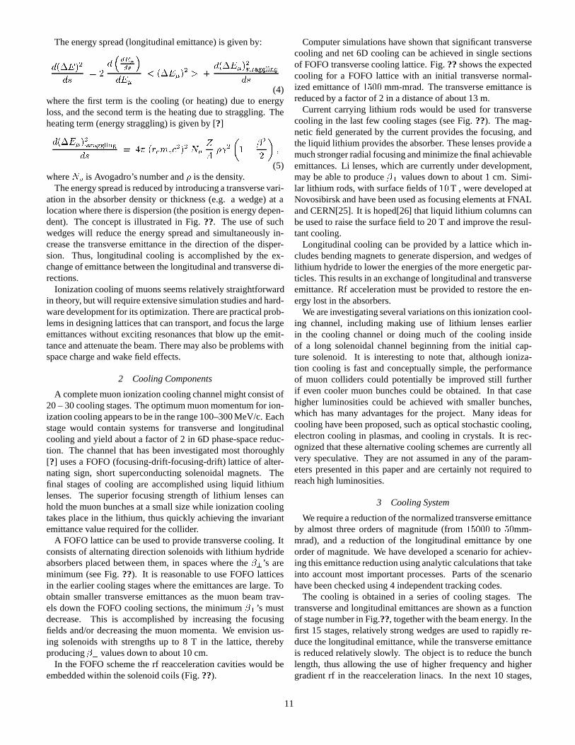
The energy spread (longitudinal emittance) is given by:
d(�E)2
ds= 2
d�dE�
ds
�dE�
< (�E�)2 > +
d(�E�)2straggling
ds(4)
where the first term is the cooling (or heating) due to energyloss, and the second term is the heating due to straggling. Theheating term (energy straggling) is given by [?]
d(�E�)2straggling
ds= 4� (remec
2)2 No
Z
A� 2
�1�
�2
2
�;
(5)whereNo is Avogadro’s number and� is the density.
The energy spread is reduced by introducing a transverse vari-ation in the absorber density or thickness (e.g. a wedge) at alocation where there is dispersion (the position is energy depen-dent). The concept is illustrated in Fig.??. The use of suchwedges will reduce the energy spread and simultaneously in-crease the transverse emittance in the direction of the disper-sion. Thus, longitudinal cooling is accomplished by the ex-change of emittance between the longitudinal and transverse di-rections.
Ionization cooling of muons seems relatively straightforwardin theory, but will require extensive simulation studies and hard-ware development for its optimization. There are practical prob-lems in designing lattices that can transport, and focus the largeemittances without exciting resonances that blow up the emit-tance and attenuate the beam. There may also be problems withspace charge and wake field effects.
2 Cooling Components
A complete muon ionization cooling channel might consist of20 – 30 cooling stages. The optimum muon momentum for ion-ization cooling appears to be in the range 100–300 MeV/c. Eachstage would contain systems for transverse and longitudinalcooling and yield about a factor of 2 in 6D phase-space reduc-tion. The channel that has been investigated most thoroughly[?] uses a FOFO (focusing-drift-focusing-drift) lattice of alter-nating sign, short superconducting solenoidal magnets. Thefinal stages of cooling are accomplished using liquid lithiumlenses. The superior focusing strength of lithium lenses canhold the muon bunches at a small size while ionization coolingtakes place in the lithium, thus quickly achieving the invariantemittance value required for the collider.
A FOFO lattice can be used to provide transverse cooling. Itconsists of alternating direction solenoids with lithium hydrideabsorbers placed between them, in spaces where the�?’s areminimum (see Fig.??). It is reasonable to use FOFO latticesin the earlier cooling stages where the emittances are large. Toobtain smaller transverse emittances as the muon beam trav-els down the FOFO cooling sections, the minimum�?’s mustdecrease. This is accomplished by increasing the focusingfields and/or decreasing the muon momenta. We envision us-ing solenoids with strengths up to 8 T in the lattice, therebyproducing�? values down to about 10 cm.
In the FOFO scheme the rf reacceleration cavities would beembedded within the solenoid coils (Fig.??).
Computer simulations have shown that significant transversecooling and net 6D cooling can be achieved in single sectionsof FOFO transverse cooling lattice. Fig.??shows the expectedcooling for a FOFO lattice with an initial transverse normal-ized emittance of1500 mm-mrad. The transverse emittance isreduced by a factor of 2 in a distance of about 13 m.
Current carrying lithium rods would be used for transversecooling in the last few cooling stages (see Fig.??). The mag-netic field generated by the current provides the focusing, andthe liquid lithium provides the absorber. These lenses provide amuch stronger radial focusing and minimize the final achievableemittances. Li lenses, which are currently under development,may be able to produce�? values down to about 1 cm. Simi-lar lithium rods, with surface fields of10T , were developed atNovosibirsk and have been used as focusing elements at FNALand CERN[25]. It is hoped[26] that liquid lithium columns canbe used to raise the surface field to 20 T and improve the resul-tant cooling.
Longitudinal cooling can be provided by a lattice which in-cludes bending magnets to generate dispersion, and wedges oflithium hydride to lower the energies of the more energetic par-ticles. This results in an exchange of longitudinal and transverseemittance. Rf acceleration must be provided to restore the en-ergy lost in the absorbers.
We are investigating several variations on this ionization cool-ing channel, including making use of lithium lenses earlierin the cooling channel or doing much of the cooling insideof a long solenoidal channel beginning from the initial cap-ture solenoid. It is interesting to note that, although ioniza-tion cooling is fast and conceptually simple, the performanceof muon colliders could potentially be improved still furtherif even cooler muon bunches could be obtained. In that casehigher luminosities could be achieved with smaller bunches,which has many advantages for the project. Many ideas forcooling have been proposed, such as optical stochastic cooling,electron cooling in plasmas, and cooling in crystals. It is rec-ognized that these alternative cooling schemes are currently allvery speculative. They are not assumed in any of the param-eters presented in this paper and are certainly not required toreach high luminosities.
3 Cooling System
We require a reduction of the normalized transverse emittanceby almost three orders of magnitude (from15000 to 50mm-mrad), and a reduction of the longitudinal emittance by oneorder of magnitude. We have developed a scenario for achiev-ing this emittance reduction using analytic calculations that takeinto account most important processes. Parts of the scenariohave been checked using 4 independent tracking codes.
The cooling is obtained in a series of cooling stages. Thetransverse and longitudinal emittances are shown as a functionof stage number in Fig.??, together with the beam energy. In thefirst 15 stages, relatively strong wedges are used to rapidly re-duce the longitudinal emittance, while the transverse emittanceis reduced relatively slowly. The object is to reduce the bunchlength, thus allowing the use of higher frequency and highergradient rf in the reacceleration linacs. In the next 10 stages,
11

the emittances are reduced close to their asymptotic limits. Inthe last stages, the emittance is further reduced in current car-rying lithium rods. In order to obtain the required very lowequilibrium transverse emittance, the energy is allowed to fallto 15 MeV, thus increasing the focusing strength and loweringthe�?. The result is an effective exchange of longitudinal andtransverse emittances, with little change in the overall six di-mensional phase space. The total length of the system is 750m, and the total acceleration used is 4.7 GeV. The fraction ofmuons that have not decayed and are available for accelerationis calculated to be55%.
As an interesting example, in Fig.?? results are shown froma simulation of a cooling channel constructed entirely fromlithium lenses plus reacceleration. The cooling channel consistsof twelve 2 m long lithium lenses with reacceleration at the endof each lens. The gradient is increased from lens to lens, fol-lowing the reduction in beam size as the beam is cooled. Thecalculation predicts a reduction in the normalized rms trans-verse emittance from� 10000� mm-mrad to80� mm-mrad.The parameters of the simulated cooling setup have not beenoptimized. However, the predicted final transverse emittance isalready consistent with the requirements for a high-luminositymuon collider.
The Monte Carlo studies to date demonstrate convincinglythat a single lithium lens can effectively reduce the emittance.However, the angular divergence of the muons entering andleaving the lens has to be large, and more detailed simulationsare needed to test the feasibility of focusing the beam into therod and capturing it as it leaves, all without emittance growth.
4 Recent Progress and Outlook
Although our current cooling scenario represents a plausiblemethod for achieving the required muon cooling by a factor of106, much work remains to be done in order to flesh out allof the details. Simulations have demonstrated that single sec-tions of FOFO lattice with LiH absorbers or single Li lensescan produce transverse cooling by a factor of 2 and that singleLi wedges can produce longitudinal cooling. Simulation workis now addressing the important issue of matching the beam be-tween the various cooling components.
To achieve efficient and cost effective cooling we are propos-ing a number of new technological developments that must betested experimentally. For example, the FOFO lattice we areproposing uses pillbox rf cavities. This gives the maximum pos-sible electric field gradient on the axis, but, since the cavity doesnot have irises, requires the beam to cross the cavity walls. Therf cavities have to operate inside a strongly varying solenoidalfield. To reduce the required rf power we are proposing to op-erate the cavity at liquid nitrogen temperature. For the lithiumlens we are proposing longer and smaller diameter lenses thanany previously built. We are also requiring the lens system tooperate for significantly more pulses than current lenses.
For theses reasons we intend to design and prototype criticalsections of the muon ionization cooling channel. The measure-ments that are needed to demonstrate the cooling capability andoptimize the design of the FOFO and lithium lens cooling stages
will require the construction and operation of a new IonizationCooling Test Facility [?], which is described in section ???.
D Acceleration
The accelator for the muons is physically the largest com-ponent of a muon collider and is also expected to be the mostexpensive component for higher energy colliders.
1 Acceleration Options
The muons must be rapidly accelerated to avoid decay. How-ever, a single linac, such as those required for electron-positroncolliders, is a very expensive option. Instead, one can econo-mize on the expensive r.f. cavities by instead using a recirculat-ing linac similar to that used at CEBAF.
2 Possible Alternatives to a Recirculating Linac
While a recirculating linac appears to be the logical choicefor muon colliders at CoM energies of order 100 GeV, twoother less conventional options are being investigated to see ifthey might be cheaper for higher energy accelerators: either fastramping dipole magnets interspersed with r.f. cavities or com-bined function (dipole-plus-quadrupole) magnets in a recircu-lating lattice.
3 Fast Ramping Dipole Magnets
Of these two options, the fast ramping dipole magnets havebeen investigated in more detail. Special materials are neededto minimize the eddy currents in the magnets. Options includesilicon steel (BNL) or metglass (Univ. Mississippi) laminationsor finemet laminated tape or powdered solid (both from NIRS,Japan).
For the final acceleration stages in high energy machines, thepower consumed by a ring using only pulsed magnets would beexcessive, but if rings of alternating pulsed and superconductingmagnets[28, 29] are used, then the power consumption can bemade reasonable.
4 Performance of an Example Acceleration Scenario
Computer simulations[27] tracking particles through a se-quence of recirculating accelerators similar to fig. 1 found adilution of longitudinal phase space of the order of15%, witha particle loss of approximately 33%, due almost entirely to de-cays.
E Collider Storage Ring
1 Introduction
A ring design for a high-luminosity, 2-TeV muon collider isparticularly challenging with its low beta, isochronicity, andheavy shielding requirements [?]. A preliminary design of anentire collider ring has been completed which meet the con-straints, including the technical ones, of such a collider.
Because of the beam’s large emittance and beam size, as com-pared with linear colliders, for example, the�� at the IP must beexceptionally small; i.e.3x10�3m, in order to reach the design
12
luminosity given the specifications. The ring design is furthercomplicated by an additional requirement, that of isochronicity.To prevent the short3mm bunch from spreading in time, with-out applying substantial rf, implies that the momentum com-paction factor must be in the range10�5to10�6. The result-ing highly nonlinear Interaction Region (IR) combined with theisochronicity condition make designing a lattice for a muon col-lider exceptionally challenging.
2 Lattice
The lattice for a 2-TeV on 2-TeV muon collider must sat-isfy three major design constraints. The first and most diffi-cult of these is provision of an Interaction Region (IR) withan extremely low�� (� 3 mm) consistant with an acceptabledynamic aperture. This requirement is complicated by the ne-cessity to incorporate considerable shielding in and around thesuperconducting magnets to protect them from the high muon-decay backgrounds [?]. Second, the ring must exhibit a highdegree of isochronicity in order to preserve short3mm longbunches with a modest rf system. Lastly, there must be smallcorrected chromaticity, so that the momentum-dependent tunespread of the beam does not severely restrict the momentumaperture. The following sections describe a lattice, which is in-tended to meet the above requirements.
The ring has a roughly oval shape, with reflection symme-try about the vertical axis. The lattice has two circular arcs,separated by the experimental insertion and a utility insertionfor injection, extraction, and beam scraping. The two arcs areidentical; each contains 14 periodic cells or modules. One ad-ditional arc module located at the experimental-insertion end ofeach arc can be perturbed and rematched to allow adjustment ofthe machine tunes without impacting lattice functions in the restof the ring. Consequently the ring structure, both geometricallyand optically, has a single superperiod, and reflection symmetryabout the line joining the centers of the two insertions.
Arc module In order to have very short3mm bunches inthe 2-TeV muon collider, the storage ring must be quasi-isochronous, which requires that the momentum compaction� be very close to zero. Furthermore, the lattice must be de-signed so that over the required momentum range, the momen-tum compaction remains small. Since the experimental inser-tion has bending regions with positive contributions to�, thecontributions of the arcs must be negative.
A negative value of� in the arcs is obtained by invokingthe approach used in flexible momentum compaction (FMC)modules[?]; where two FODO cells are connected by a match-ing region with horizontal phase advance of nearly� (low �x).This drives the dispersion� to a negative value at the ends ofthe module and makes�bends � 0.
The specific module used for this muon collider lattice(Fig. ??) has been modified by including an insertion with avertical phase advance of nearly� (low �y) at the end of themodule. This modification has several advantages comparedto the standard FMC module. Firstly, the negative dispersionregion has been flattened and lengthened so that the value of� is mainly determined by the bends placed in the dispersion
plateaus–making it much less sensitive to�0, and thus providinga wider range of quadrupole settings and corresponding latticefunctions which satisfy the negative or low-� criterion. In fact,� can be tuned with a sensitivity of10�5 to 10�7 through theuse of paired trim dipoles in these two regions alone; therebypreserving both lattice functions and closure. Over a range in� of �10�4 to+10�4 the impact on the lattice functions in therest of the ring is negligible.
Secondly, the vertical phase advance of the module is nolonger nearly an integer, but is identical to the horizontal phaseadvance,1:5�. This is particularly important, because when thecorresponding sextupoles in successive modules are separatedby odd multiples of� in both planes, one obtains partial can-cellation of their geometrical effects. (The near� vertical phaseadvance caused off-momentum particles to experience integer-related resonances in the long arc strings when sextupole cor-rectors were on.)
Thirdly, the regions of high-�x, low-�y and low-�x, high-�yin this arc module are ideal locations for sextupoles for chro-matic correction of the arcs and reduction of the variations of� with momentum. A pair of horizontal sextupoles adjacent tothe center doublets are especially effective in eliminating the de-pendence of� on momentum offset. With these two sextupolesthe variation of� over the momentum range of�:004 can berestricted to less than10�6, cancelling the dependence to ap-proximately third order.
Experimental insertion The design of an insertion withan extremely low-beta interaction region for a muon colliderpresents a challenge similar to that encountered for the NextLinear Collider (NLC)[?]. The design used here for each halfof the symmetric low-beta insertion follows the prescriptionproposed by Brown[?]; it consists of two telescopes with achromatic correction section between. Therefore, the experi-mental insertion consists of three parts: the Final Focus Tele-scope (FFT) or IR, a Chromatic Correction Section (CCS), anda Matching Telescope (MT). Fig.?? shows the right half of theinsertion beginning at the IP. From left to right, the figure showsthe FFT, CCS, and MT.
The low beta-function values at the IP are mainly produced byfour strong superconducting quadrupoles in the FFT with NbSncoils. Their poletip fields range from 9.5 to 12 T depending onthe apertures, which determines the size of the coils and sus-tainable currents [?]. The first of the four quadrupoles begins4m away from the IP, they all have 2-cm thick tungsten linersand are interleaved with tungsten collimators to protect themfrom the intense backgrounds from muon decay [?]. Systemat-ically positioning tungsten collimators before superconductingelements is also effective in the arcs and has eliminated the needfor thick, 6-cm tungsten liners in the ring magnets.
The IR quadrupoles are followed by a pair of 15-m longbucked superconducting dipoles which sweep background par-ticles produced by muon decays away from the IR. A long spacefollows without quadrupoles but with a substantial length ofbending magnets in order to make an efficient transition into theCCS; matching� and�0 from their zero values at the IP into theCCS. In this IR design,�max in both planes is145 km. A more
13
detailed description of the experimental insertion, especially theFFT, can be found in the Snowmass proceedings[?].
The extremely high beta values in the FFT quadrupoles pro-duce large chromaticities, which must be corrected locally withsextupoles. The natural chromaticity of the FFT is -1500 inthe horizontal and -2200 in the vertical. The purpose of theCCS is to correct these large first-order chromaticities locally,relatively close to the IP, by using interleaved sextupole pairs.These sextupole pairs are located at positions with large valuesof the dispersion and of the beta function corresponding to thechromaticity to be corrected by that pair.
In this design, these� values are10 km in the plane beingcorrected and:5 � :7m in the opposite plane. The dispersionis 3:4m at the horizontal sextupoles and1:5m at the verticalones. The sextupoles which comprise each pair are separatedby betatron-phase intervals of� = �. Additionally, they arelocated at positions where the phase interval from the IP is anodd multiple of�=2. The vertical-correction sextupole is closestto the IP, since the vertical chromaticity is the largest.
This sextupole arrangement cancels the second-order geomet-ric aberrations of the sextupoles, which reduces the second or-der tune shift by several orders of magnitude. The large ratio be-tween the beta functions allows the sextupoles to be interleavedand still maintain the delicate higher-order cancellation. Short-ening the chromatic correction section–especially with respectto the number of maxima and minima included for sextupoles–proves to be very important in improving the dynamic aper-ture. Placement of sextupoles at minima in the plane not be-ing corrected reduces significantly the aberrations arising fromsextupole length and cross-plane correlations.
Utility insertion The utility insertion has been specifically de-signed with high-beta regions to facilitate beam scraping andextraction of unwanted beam, and injection and extraction. Adetailed discussion of this insertion can be found in followingsections [?].
Work on improving the experimental insertion at first concen-trated on reducing its chromaticity by altering the FFT, but it tproved necessary also to optimize the CCS and and the globalphase advance to improve the dynamic aperture. When the peakbeta functions in the CCS were lowered from 100 to 50 km, thedispersion raised in the insertion sextupoles, and the workingpoint optimized using the phase trombones, the dynamic aper-ture increases from 1 to 5 sigma. Further studies indicated thata 10 km version of the CCS with the same final focus structurehad an even more improved dynamic aperture due to a much re-duced tuneshift with amplitude created by the strong chromaticcorrection sextupoles.
In a sextupole-dominated ring, as is the muon collider, eitherthe large and negative tuneshift with amplitude must be cor-rected or a working point must be chosen which is just belowthe integer or half integer to provide the maximum displace-ment from these resonances as a function of beam amplitude.The tuneshift with amplitude can be corrected using sextupolesin dispersion-free regions. These sextupoles are generally ro-tated from the standard sextupole orientation which is set tocancel chromatic aberrations in regions of positive dispersion.
Including nonstandard orientations of sextupoles has not beenimplemented in some of the beam optics codes being used inthe design work and this is presently being addressed.
The chromaticity must be corrected in order to provide a rea-sonable momentum aperture. The overall momentum band-width of the system is limited by third-order aberrations andresidual second-order amplitude-dependent tune shifts. Theseaberrations arise from small phase errors between the sex-tupoles and the final quadruplet, and from the finite lengths ofthe sextupoles. Presently, the entire ring has a dynamic apertureof greater than5 sigma and a momentum acceptance larger than�:15%. The base working design stands to be improved fur-ther by raising the dispersion in the utility sections (from .6 mat the sextupoles) and by implementing higher-order correctionschemes; as was done in another collider lattice design by K.Oide [?], which has many good features and performance.
F Detector and Shielding of Interaction Region
1 Background Environment
Background in the detector comes from 3 main sources: 1)muon decays near the detector, 2) muon halo and 3) beam-beaminteractions. We will discuss these 3 background contributionsin turn.
Table II gives the fluxes of different particles at a radius of10 cm from the vertex, obtained by one of the Monte Carlostudies[38].
The beam pipe must be surrounded by a tungsten shield thatis extended, as a cone, down towards the vertex. Designs havebeen studied in which this cone had a half angle of between10 and 20 degrees, and extended to within 6 to 15 cm of thevertex. Different dimensions and shapes have been tried, andthe optimum design is yet to be determined. In addition, carefuldesign of beam collimators approaching the intersection point isrequired, and boron or other neutron absorbing materials mustbe used.
With such shields, the backgrounds estimated from MonteCarlo studies, indicate that a suitable detector should be ableto operate and physics be analyzed. Recent optimization of theshielding for the 4 TeV design has reduced the background lev-els by roughly an order of magnitude from the levels reportedin Snowmass96, down to a level comparable to those expectedin the LHC detectors. Studies on a 0.5 TeV design yield similarbackground levels, while initial studies on the 100 GeV Higgsfactory show a somewhat worse situation. Further shielding op-timization is expected to improve the situation, particularly forthe 100 GeV design.
There could be a very serious background from the presenceof even a very small halo of near full energy muons in the circu-lating beam[40]. These muons can pass through the calorime-ter and deposit significant clumps of energy from deep-inelasticscattering processes.
The beam will need careful preparation before injection intothe collider, and a collimation system will have to be designedto be located on the opposite side of the ring from the detector.
There is also a small background from incoherent electron-positron pair production in the 4 TeV Collider case[41]. The
14

cross section is estimated to be10mb[42], which would giverise to a background of� 3 104 electron pairs per bunch cross-ing. However, most of these electrons are curled up by thesolenoidal magnetic field of the magnet and do not escape intothe detector, so this background does not appear to be a partic-ularly serious problem. Coherent pair production has also beenshown not to create a problem for the detector.
Table II: Background rates at a 10 cm radius. ** needsIulio/Mokhov update **
Silicon Drift Micro TPCflux < E > hits Occup. hits Occup.cm�2 MeV cm�2 % cm�2 %
10000 1 20 2 .5 10�
n 3000 10 3 0.3 .06 .01e� 20 1 20 2 20 4�� 10 240 10 1 10 2p 2 30 2 0.2 2 0.4�� 1 24000 1 0.1 1 0.2total 56 6 34 17�
2 Current Status and Outlook
The choice of detectors must take into account the require-ments of the physics and their ability to operate in the back-ground environment. A major design goal is to be able to placethe inner layer of the vertex detector close enough to the inter-action point to allow effect separation of charm from bottomquarks.
The effect of these backgrounds in the electromagneticcalorimeter, assumed to have 2 x 2 cm towers, would be to in-troduce pedestals of about 100 MeV and fluctuations of about50 MeV: neither serious. In the hadron calorimeter, the effectof all backgrounds, except the muons, would be to introduce a 2GeV pedestals with 300 MeV fluctuations: also acceptable. Butthe muons, arising from Bethe-Heitler pair production in EMshowers or from a halo in the machine, though modest in num-ber, have high average energies. They would not be a problem inthe tracking detectors. But in the calorimeters, they would occa-sionally induce deeply inelastic interactions, depositing clumpsof energy deep in the absorbers. If a calorimeter is not able torecognize the direction of such interactions (they will be point-ing along the beam axis) then they would produce unacceptablefluctuations in hadron energy determination. It has been sug-gested that segmenting the calorimetry in depth would allowthese interactions to be subtracted.
15

VII RESEARCH AND DEVELOPMENT PLAN
This section gives an outline of our current research and de-velopment (R and D) studies and our plans for the next fewyears. Currently, our R and D largely consists of theoreticaldesign studies, involving heavy use of computer simulations.
Theoretical studies are expected to remain a large part of ourR and D over the next few years, but they will be increasinglyaugmented with an experimental program to test and developcritical components and concepts, in preparation for the detaildedesign and, hopefully, construction of a first muon collider fa-cility.
The first subsection describes the current and planned scopeof our theoretical studies. In the following two subsections,plans are presented for two proposed experimental R & D facil-ities, one to study ionization cooling and the other to study theproduction and capture of large bunches of pions. Smaller ex-periments are then discussed, before summarizing the expectedlogistical requirements of our experimental program.
A Theoretical Studies
1 Overview
Theoretical studies involve verification, design and optimiza-tion of muon colliders. They are expected to progress over thenext few years from rather general studies to more detailed de-sign and a full exploration of options for each of the compo-nents.
2 Theoretical R and D on Cooling
With the recent successes in reducing the expected detectorbackgrounds to a manageable level (see section ??) the mostcritical item for theoretical R and D is now the muon coolingchannel.
Since all of the physics involved in cooling is well understoodand relatively straightforward to model, the design of the muoncooling channel will come largely from computer simulationsrather than hardware demonstrations These computer simula-tions can be developed on a somewhat shorter timescale thanrequired for experiments. Our goal for the coming year is tohave a relatively complete simulation for a cooling channel de-sign that meets our 6-D emittance goal, and we can already ex-pect to have a rather high level of confidence in our design whenthe R & D eperiments come online in about 3 years time.
The only part of the computer simulation that will not be di-rectly calibrated by the R & D experiments is collective effectson the muon bunches when cooled to low emittance. Thereare established techniques for calculating these collective ef-fects in which essentially, the model of the bunch is partitionedinto ”macroparticles” which are then subjected to the forces pre-dicted by Maxwell’s equations. As detailed in section ???, col-lective effects have already been partially installed in our com-puter simulations and should be fully modelled in the near fu-ture.
Optimization of the muon cooling channel could lead to fastercooling and smaller final emittances, which should lead directly
to increased luminosity with smaller bunch sizes and more re-laxed technical specifications.
For example, it is quite conceivable that big gains in the cool-ing might come from adding final cooling stages to slow themuon bunches to well below the speed of light. Both the 6-dimensional cooling rates and the equilibrium emittances canimprove enormously at these lower momenta if we work outhow to deal with the larger angular spreads and the blow-upin longitudinal emittance. More speculative alternative coolingmethods also have a chance of improving the muon cooling.Alternatives that are beginning to be looked at include opticalstochastic cooling and various schemes with very low energymuons. We expect to have detailed evaluations of all alterna-tive methods for cooling, including cooling at lower momenta,in about 1 year’s time.
B Ionization Cooling Facility (ICF)
The experiments required to demonstrate ionization coolingand to develop and optimize the cooling hardware will not betrivial. They will require an ionization cooling test facility[?]with the following capabilities:
� Injection of single muons with momenta in the range 100 -300 MeV/c into a test cooling setup of length up to� 50m.
� Measurement of the six-dimensional phase-space volumeoccupied by the populations of the incoming and outgoingmuons with a precision of a few %.
� Measurement of the non-decay loss of muons travers-ing the cooling setup with a precision corresponding toO(10%) for a full cooling stage. Since the non-decaylosses are expected to be�1%, each measurement will re-quire O(10000) muons within the phase-space acceptanceof the cooling apparatus.
To provide these capabilities the facility will need to havea low energy muon beamline, the infrastructure to operate thecooling prototypes to be tested (services, shielding, overheadcrane coverage, refrigerants for superconducting magnets, rfpower for accelerating cavities including modulators, klystrons,etc), and instrumentation to identify incoming and outgoingmuons and determine their positions, directions, momenta, andtheir entrance and exit times with respect to the rf accelerationcycle. Work on an initial design of the required facility is pro-ceeding.
We propose to design and prototype critical sections of themuon ionization cooling channel. These sections would betested by measuring their performance when exposed to singleincoming muons with momenta in the range 100 – 300 MeV/c.The phase-space volume occupied by the population of muonsupstream and downstream of the cooling sections would bemeasured sufficiently well to enable cooling to be demonstrated,the calculations used to design the cooling system to be tested,and optimization of the cooling hardware to be studied. Ourgoal is to develop the muon ionization cooling hardware to thepoint where a complete ionization cooling channel can be con-fidently designed for the First Muon Collider.
16
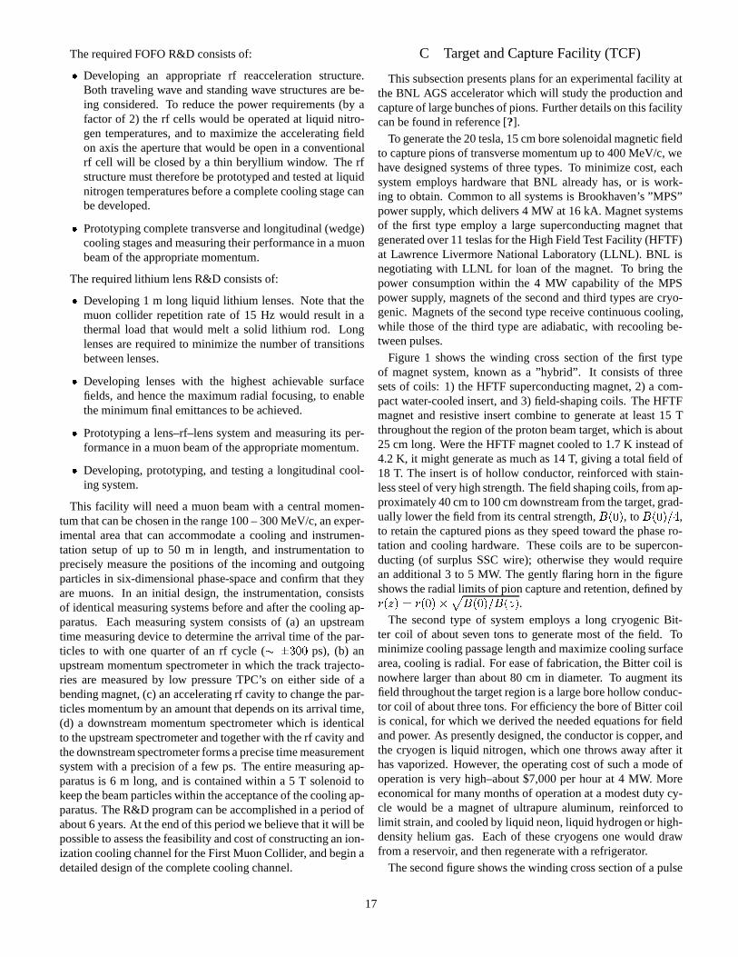
The required FOFO R&D consists of:
� Developing an appropriate rf reacceleration structure.Both traveling wave and standing wave structures are be-ing considered. To reduce the power requirements (by afactor of 2) the rf cells would be operated at liquid nitro-gen temperatures, and to maximize the accelerating fieldon axis the aperture that would be open in a conventionalrf cell will be closed by a thin beryllium window. The rfstructure must therefore be prototyped and tested at liquidnitrogen temperatures before a complete cooling stage canbe developed.
� Prototyping complete transverse and longitudinal (wedge)cooling stages and measuring their performance in a muonbeam of the appropriate momentum.
The required lithium lens R&D consists of:
� Developing 1 m long liquid lithium lenses. Note that themuon collider repetition rate of 15 Hz would result in athermal load that would melt a solid lithium rod. Longlenses are required to minimize the number of transitionsbetween lenses.
� Developing lenses with the highest achievable surfacefields, and hence the maximum radial focusing, to enablethe minimum final emittances to be achieved.
� Prototyping a lens–rf–lens system and measuring its per-formance in a muon beam of the appropriate momentum.
� Developing, prototyping, and testing a longitudinal cool-ing system.
This facility will need a muon beam with a central momen-tum that can be chosen in the range 100 – 300 MeV/c, an exper-imental area that can accommodate a cooling and instrumen-tation setup of up to 50 m in length, and instrumentation toprecisely measure the positions of the incoming and outgoingparticles in six-dimensional phase-space and confirm that theyare muons. In an initial design, the instrumentation, consistsof identical measuring systems before and after the cooling ap-paratus. Each measuring system consists of (a) an upstreamtime measuring device to determine the arrival time of the par-ticles to with one quarter of an rf cycle (� �300 ps), (b) anupstream momentum spectrometer in which the track trajecto-ries are measured by low pressure TPC’s on either side of abending magnet, (c) an accelerating rf cavity to change the par-ticles momentum by an amount that depends on its arrival time,(d) a downstream momentum spectrometer which is identicalto the upstream spectrometer and together with the rf cavity andthe downstream spectrometer forms a precise time measurementsystem with a precision of a few ps. The entire measuring ap-paratus is 6 m long, and is contained within a 5 T solenoid tokeep the beam particles within the acceptance of the cooling ap-paratus. The R&D program can be accomplished in a period ofabout 6 years. At the end of this period we believe that it will bepossible to assess the feasibility and cost of constructing an ion-ization cooling channel for the First Muon Collider, and begin adetailed design of the complete cooling channel.
C Target and Capture Facility (TCF)
This subsection presents plans for an experimental facility atthe BNL AGS accelerator which will study the production andcapture of large bunches of pions. Further details on this facilitycan be found in reference [?].
To generate the 20 tesla, 15 cm bore solenoidal magnetic fieldto capture pions of transverse momentum up to 400 MeV/c, wehave designed systems of three types. To minimize cost, eachsystem employs hardware that BNL already has, or is work-ing to obtain. Common to all systems is Brookhaven’s ”MPS”power supply, which delivers 4 MW at 16 kA. Magnet systemsof the first type employ a large superconducting magnet thatgenerated over 11 teslas for the High Field Test Facility (HFTF)at Lawrence Livermore National Laboratory (LLNL). BNL isnegotiating with LLNL for loan of the magnet. To bring thepower consumption within the 4 MW capability of the MPSpower supply, magnets of the second and third types are cryo-genic. Magnets of the second type receive continuous cooling,while those of the third type are adiabatic, with recooling be-tween pulses.
Figure 1 shows the winding cross section of the first typeof magnet system, known as a ”hybrid”. It consists of threesets of coils: 1) the HFTF superconducting magnet, 2) a com-pact water-cooled insert, and 3) field-shaping coils. The HFTFmagnet and resistive insert combine to generate at least 15 Tthroughout the region of the proton beam target, which is about25 cm long. Were the HFTF magnet cooled to 1.7 K instead of4.2 K, it might generate as much as 14 T, giving a total field of18 T. The insert is of hollow conductor, reinforced with stain-less steel of very high strength. The field shaping coils, from ap-proximately 40 cm to 100 cm downstream from the target, grad-ually lower the field from its central strength,B(0), toB(0)=4,to retain the captured pions as they speed toward the phase ro-tation and cooling hardware. These coils are to be supercon-ducting (of surplus SSC wire); otherwise they would requirean additional 3 to 5 MW. The gently flaring horn in the figureshows the radial limits of pion capture and retention, defined byr(z) = r(0)�
pB(0)=B(z).
The second type of system employs a long cryogenic Bit-ter coil of about seven tons to generate most of the field. Tominimize cooling passage length and maximize cooling surfacearea, cooling is radial. For ease of fabrication, the Bitter coil isnowhere larger than about 80 cm in diameter. To augment itsfield throughout the target region is a large bore hollow conduc-tor coil of about three tons. For efficiency the bore of Bitter coilis conical, for which we derived the needed equations for fieldand power. As presently designed, the conductor is copper, andthe cryogen is liquid nitrogen, which one throws away after ithas vaporized. However, the operating cost of such a mode ofoperation is very high–about $7,000 per hour at 4 MW. Moreeconomical for many months of operation at a modest duty cy-cle would be a magnet of ultrapure aluminum, reinforced tolimit strain, and cooled by liquid neon, liquid hydrogen or high-density helium gas. Each of these cryogens one would drawfrom a reservoir, and then regenerate with a refrigerator.
The second figure shows the winding cross section of a pulse
17

magnet for pion capture and retention. To bring the power de-mands of the magnet within the capability of the MPS powersupply, one precools the windings to 77 K. Furthermore, oneenergizes the coils sequentially, rather than all at once. Specifi-cally, one employs the outer set of four coils to energize the in-ner set. One first energizes the outer set of four coils at full volt-age for 15 to 20 seconds, to reach the current limit of the powersupply. The outer set then generates a central field of about 10T and stores about 20 MJ. By discharging this set through aroom-temperature resistor, one generates a terminal voltage ofa few kilovolts – an order of magnitude greater than that of thepower supply. In about a third of a second, the outer coil hasdischarged from 16 kA to about 13 kA and has charged the in-ner set of coils to about 11 kA. The inner set then contributesabout 12 T to the central field. The total field throughout theregion of the target is at least 20 T. Like the cryogenic systems,the pulse systems described here need about ten tons of cop-per, some as hollow conductor and some in the cheaper form ofsolid conductor. These latest designs should allow a duty cycleof many pulses per hour. The operating cost for liquid nitrogenis only ten dollars per pulse. Note that coils are conical in bothbore and outer diameter. Once again we needed to derive theequations for field and power.
The cost of the hybrid magnet systems we estimate to beabout two million dollars. The cryogenic magnet systemsshould cost only about a third as much. However, they either areexpensive to run, or else generate pulses that last only a fractionof a second. Therefore, the preferred system, despite its highercapital cost, is the hybrid.
D Other Experimental R & D
Prototype work would also be required on other magnets, r.f.systems, modulators etc. The definition of such a program willbe one of the tasks of the near-term R & D effort.
[[status: rewrite this paragraph]]
1 Accelerator Experiments
An accelerator experiment has already been conducted tostudy the preparation of short proton bunches suitable for thepion production target at a muon collider. Other experimentsare underway to study the reduction of space charge in protonstorage rings.
Experiment E-932 at the AGS has shown one can reduce thebunch length from 10 ns to 3 ns for 1.5 eV-sec bunches by oper-ating close to transition, and the bunches are stable for usefullylong times. It should be possible to demonstrate proton buncheswith sigma = 1 - 2 ns using either bunch rotation far from tran-sition, possibly using a harmonic cavity to control nonlinear ef-fects, or rotation near transition, followed by rotation far fromtransition. Experiments at the AGS, the Fermilab Booster andthe KEK proton synchrotron are being considered. The transi-tion jump system would be used to change the machine latticeas required.
Longitudinal space charge effects can be troublesome both atinjection and during the final bunching process. The use of tun-able inductive inserts in the vacuum chamber could permit ac-
tive control and compensation of the longitudinal space chargevoltage below transition. Experiments underway at the PSR atLos Alamos using biased ferrite rings to modify and control thewall impedance have shown that longitudinal space charge ef-fects can be modified. Preliminary experiments have also beendone at KEK which indicate that the technique should be use-ful [?].
2 Measurement of Pion Production Cross Sections
The collaboration has joined a BNL nuclear physics exper-iment, E910 [17, 18], that is measuring pion production fromprotons at different energies striking various heavy metal tar-gets. The data is currently being analyzed, and should allowmore realistic Monte-Carlo calculations of total pion yield andcapture in a solenoid.
3 Lithium lenses
Ionization Cooling to minimal transverse emittance requiresstrong focusing at the absorber, and that can obtained over ex-tended lengths by using a metal conductor absorber, where theenergy loss is within the metal itself and the active current fo-cuses the beam radially. For minimal multiple scattering, a low-Z material such as Li is desired, and Li lens conductors havebeen developed (for antiproton and positron collection) at BINP,Fermilab and CERN, and this technology can be extended forbeam-cooling applications. For beam-cooling, we would wantsomewhat longer lenses (¿ 1m/ unit) and 15-Hz Collider opera-tion would raise Li lenses to liquid temperatures.
Currently a three-year plan for design, construction, and test-ing of a liquid Li lens has been initiated by BINP and Fermilab.The initial plan is for a 13T, 1cm radius, 20 cm long lens forantiproton collection. That experience can be readily extendedto the 1m length needed for a cooling Li lens, and an initialdesign for a 1m lens has been presented by Silvestrov of BINP.
The cooling plan would be to extend the Liquid Li lens expe-rience to build and test a 1-m long module suitable for cooling(13T, 1 cm radius, 1m long), with the assistance of Hartouniet al. of Lawrence Livermore National Laboratory. This mod-ule would be bench-tested, and then inserted in the muon initialcooling experiment.
Obtaining minimal emittances requires stronger lenses, whichcan be obtained by increasing the surface field to 20T, whilelens radii are reduced from 1 cm toward 1mm. In a cooling se-quence, the reducing emittance will enable smaller and smallerlens radii. The R & D program would continue by producingthese higher gradient lenses, adding them to the cooling channelfor further cooling (with beam reacceleration rf), and eventuallytesting the limits of the cooling technology.
4 Magnet Experimental R & D
Superconducting dipoles, quadrupoles and solenoids are usedfrom the target station to the final interaction region. In almostall cases they will be exposed to high radiation, and the designis dominated by the desire for high field, low cost, and radiationhardness.
18
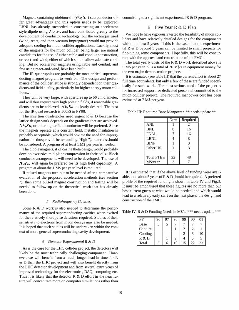
Magnets containing niobium-tin (Nb3Sn) suerconductor of-fer great advantages and this option needs to be explored.LBNL has already succeeded in constructing an acceleratorstyle dipole usingNb3Sn and have contributed greatly to thedevelopment of conductor technology, but the technique used(wind, react, and then vacuum impregnate) would not provideadequate cooling for muon collider applications. Luckily, mostof the magnets for the muon collider, being large, are naturalcandidates for the use of either cable and conduit construction,or react-and-wind; either of which should allow adequate cool-ing. But no accelerator magnets using cable and conduit, andfew using react-and-wind, have been built.
The IR quadrupoles are probably the most critical supercon-ducting magnet program to work on. The design and perfor-mance of the collider lattice is strongly dependent on their gra-dients and field quality, particularly for higher energy muon col-liders.
They will be very large, with apertures up to 50 cm diameter,and will thus require very high pole tip fields, if reasonable gra-dients are to be achieved.Nb3Sn is clearly desired. The costfor the IR quad research is 500k$ in FY98.
The insertion quadrupoles need urgent R & D because thelattice design work depends on the gradients that are achieved.Nb3Sn, or other higher field conductor will be prefered. Sincethe magnets operate at a constant field, metallic insulation isprobably acceptable, which would obviate the need for impreg-nation and thus provide better cooling. HighTc materials shouldbe considered. A program of at least 1 M$ per year is needed.
The dipole magnets, if of cosine theta design, would probablydevelop excessive mid plane compression in their coils. Blockconductor arrangements will need to be developed. The use ofNb3Sn will again be prefered for its high field capability. Aprogram at about the 1 M$ per year level is required.
If pulsed magnets turn out to be needed after a comparativeevaluation of the proposed acceleration methods (see section?) then some pulsed magnet construction and testing will beneeded to follow up on the theoretical work that has alreadybeen done.
5 Radiofrequency Cavities
Some R & D work is also needed to determine the perfor-mance of the required superconducting cavities when excitedfor the relatively short pulse durations required. Studies of theirsensitivity to electrons from muon decays may also be needed.It is hoped that such studies will be undertaken within the con-text of more general superconducting cavity development.
6 Detector Experimental R & D
As is the case for the LHC collider project, the detectors willlikely be the most technically challenging component. How-ever, we will benefit from a much longer lead-in time for R& D than the LHC project and will also benefit directly fromthe LHC detector development and from several extra years ofimproved technology for the electronics, DAQ, computing etc.Thus it is likely that the detector R & D effort in the near fu-ture will concentrate more on computer simulations rather than
committing to a significant experimental R & D program.
E Five Year R & D Plan
We hope to have vigorously tested the feasibility of muon col-liders and have relatively detailed designs for the componentswithin the next 5 years. If this is the case then the experimen-tal R & D beyond 5 years can be limited to small projects forfine-tuning some components. Hopefully, this will be concur-rent with the approval and construction of the FMC.
The total yearly costs of the R & D work described above is5 M$ per year, plus a total of 26 M$’s in equipment money forthe two major demonstration projects.
It is estimated (see table III) that the current effort is about 27full time equivalents, but only a few of these are funded specif-ically for such work. The most serious need of the project isfor increased support for dedicated personnal committed to themuon collider project. The required manpower cost has beenestimated at 7 M$ per year.
Table III: Required Base Manpower. ** needs update **
Now RequiredANL 1 2BNL 8 16FNAL 7 16LBNL 4 8BINP 1 3Other US 1 3
— —Total FTE’s 22 48M$/year 3 7
It is estimated that if the above level of funding were avail-able, then about 5 years of R & D should be required. A preferedprofile of the required funding is shown in table IV and Fig.3.It must be emphasised that these figures are no more than ourbest current guess at what would be needed, and which wouldlead to a relatively early start on the next phase: the design andconstruction of the FMC.
Table IV: R & D Funding Needs in M$’s. *** needs update ***
FY 96 97 98 99 00 01Base 3 5 7 7 7 7Capture 1 2 2 1Cooling 2 8 10R & D 1 2 4 5 5Total 3 6 10 15 22 23
19

Figure 3: Required Funding Profile. *** needs update ***
20

VIII SUMMARY
A Physics Potential of Muon Colliders
Section ?? shows that the physics case for muon colliders isvery strong, particularly for the study of the fundamental Higgsmechanism that is thought to determine the masses of all theelementary particles. It is hoped that muon colliders will helpto give a deeper understanding and unification of the elementaryforces and particles that underlie all physical processes.
A muon collider complex is expected to be considerablysmaller than other types of colliders at the high energy frontier,and it is hoped that it will also be correspondingly relativelycheaper. It is envisioned that a muon collider facility could beeasily upgradable, perhaps with several collider rings feedingoff the same source of cooled muons.
B Design Scenarios
The emphasis of our theoretical studies has shifted to lowerenergy colliders that might be good choices for first muon col-lider (FMC). If a Higgs boson is discovered with a mass belowabout 150 GeV then the FMC would probably be a factory forits resonant production.
Detailed design scenarios have advanced in the past year, par-ticularly with the addition of detailed studies for an s-channelHiggs factory at around 70 to 150 GeV. These studies have in-creased our confidence in the feasibility of muon colliders fromrelatively low energies up to multi-TeV colliders.
The understanding of the components’ performance and opti-mization at energies around 100 GeV is new, while the studiesfor the 4 TeV collider have made good progress, particularly inthe areas of detector shielding and magnet lattice design. [insummary?] Combining these studies now gives us a much bet-ter understanding of the feasibility and design issues for muoncolliders spanning the range from 100 GeV up to 4 TeV.
The one serious problem that has emerged in the past year isthe surprising potential for a radiation hazard from the copiousneutrino flux emerging from the collider. This has been foundto be not a serious problem for lower energy colliders such asan s-channel Higgs factory. However, the radiation dose risesas the cube of the CoM energy, and quickly becomes a problemat higher energies. It appears certain to force major constraintson the design and, possibly, siting of any proposed multi-TeVmuon colliders. Studies are underway to further assess and re-duce this problem.
C Progress on Components
There has been progress in our understanding of all of thecomponents of a muon collider, particularly on the two com-ponents that we consider to be the most critical: the coolingchannel and the detector shielding.
The muon cooling channel is the most novel part of a muoncollider complex. Steady progress has been made both in im-proving the design of the channel and in adding detail to thecomputer simulations. We are now much closer to the goal ofhaving a detailed and complete simulation of an entire cooling
channel. Further, a vigorous experimental program is beginningto verify and benchmark the computer simulations.
Coping with the large backgrounds in the detector was pre-sented last year as perhaps the worst problem facing muon col-liders. By optimization of the detector shielding, this problemhas already been reduced by an order of magnitude from lastyear’s 4 TeV design, and the feasibility of shielding the detectorhas now also been demonstrated at lower energies, including fora 100 GeV Higgs factory.
D Experimental R and D Program
The collaboration is now embarking on a vigorous effortto initiate an experimental R and D program to complementthe theoretical studies and computer simulations. Section ???presents an outline of the anticipated R and D program overthe next several years. This includes the construction of twofairly major experimental facilities, one to test ionization cool-ing and the other to verify the production and capture of largepion bunches.
IX CONCLUSIONS
The muon collider is a new type of proposed accelerator thathas considerable potential for contributing to the future programof experimental high energy physics.
Our collaboration is making good progress in establishing thefeasibility of muon colliders. With our current level of under-standing we believe it likely that muon colliders will be ableto achieve both high luminosities and manageable experimen-tal conditions. Although the designs are novel, the technologiesrequired seem to be nowhere more than modest extrapolationsfrom what is available today.
[[status: needs rewrite: 5 paragraphs]]
X ACKNOWLEDGMENTS
The collaborators acknowledge the dedicated efforts of manyindividuals in their home institutions. This work was supportedby the US Department of Energy under contracts DE-ACO2-76-CH00016, DE-AC02-76-CH03000 and DE-AC03-76-SF00098.
[[status: OK]]
XI REFERENCES
[1] �+�� Collider: A Feasibility Study, BNL-52503 Fermi Lab-
Conf.-96/092 LBNL-38946; also Proceedings of the SnowmassWorkshop 96, to be published.
[2] E. A. Perevedentsev and A. N. Skrinsky, Proc. 12th Int. Conf. onHigh Energy Accelerators, F. T. Cole and R. Donaldson, Eds.,(1983) 485; A. N. Skrinsky and V.V. Parkhomchuk, Sov. J. ofNucl. Physics12, (1981) 3;Early Concepts for�+�� Collidersand High Energy� Storage Rings, Physics Potential & Develop-ment of�+�� Colliders. 2nd Workshop, Sausalito, CA, Ed. D.Cline, AIP Press, Woodbury, New York, (1995).
[3] D. Neuffer, IEEE Trans.NS-28, (1981) 2034.
[4] Proceedings of the Mini-Workshop on�+�� Colliders: Parti-cle Physics and Design, Napa CA, Nucl Inst. and Meth.,A350
21

(1994) ; Proceedings of the Muon Collider Workshop, February22, 1993, Los Alamos National Laboratory Report LA- UR-93-866 (1993) andPhysics Potential & Development of�+�� Col-liders 2nd Workshop, Sausalito, CA, Ed. D. Cline, AIP Press,Woodbury, New York, (1995).
[5] Transparencies at the2 + 2 TeV�+�� Collider CollaborationMeeting, Feb 6-8, 1995, BNL, compiled by Juan C. Gallardo;transparencies at the2 + 2 TeV�+�� Collider CollaborationMeeting, July 11-13, 1995, FERMILAB, compiled by RobertNoble; Proceedings of the 9th Advanced ICFA Beam DynamicsWorkshop, Ed. J. C. Gallardo, AIP Press, Conference Proceed-ings 372 (1996).
[6] D. V. Neuffer and R. B. Palmer, Proc. European Particle Acc.Conf., London (1994); M. Tigner, in Advanced Accelerator Con-cepts, Port Jefferson, NY 1992, AIP Conf. Proc.279, 1 (1993).
[7] R. B. Palmer et al.,Monte Carlo Simulations of Muon Produc-tion, Physics Potential & Development of�+�� Colliders 2nd
Workshop, Sausalito, CA, Ed. D. Cline, AIP Press, Woodbury,New York, pp. 108 (1995); R. B. Palmer, et al.,Muon ColliderDesign, in Proceedings of the Symposium on Physics Potential& Development of�+�� Colliders, Elsevier, in press
[8] V. Barger, et al. and J. Gunion et al., this proceedings. V. Barger,New Physics Potential of Muon-Muon Collider, Proceedings ofthe 9th Advanced ICFA Beam Dynamics Workshop, Ed. J. C.Gallardo, AIP Press, Conference Proceedings 372 (1996).
[9] T. Roser,AGS Performance and Upgrades: A Possible ProtonDriver for a Muon Collider, Proceedings of the 9th AdvancedICFA Beam Dynamics Workshop, Ed. J. C. Gallardo, AIP Press,Conference Proceedings 372 (1996) .
[10] Y. Cho, et al.,A 10-GeV, 5-MeV Proton Source for a Pulsed Spal-lation Source, Proc. of the 13th Meeting of the Int’l Collaborationon Advanced Neutron Sources, PSI Villigen, Oct. 11-14 (1995);Y. Cho, et al.,A 10-GeV, 5-MeV Proton Source for a Muon-MuonCollider, Proceedings of the 9th Advanced ICFA Beam Dynam-ics Workshop, Ed. J. C. Gallardo, AIP Press, Conference Pro-ceedings 372 (1996).
[11] F. Mills, et al., presentation at the 9th Advanced ICFA Beam Dy-namics Workshop, unpublished; see also second reference in [5].
[12] T. Roser and J. Norem, private communication.
[13] D. Kahana, et al.,Proceedings of Heavy Ion Physics at the AGS-HIPAGS ’93, Ed. G. S. Stephans, S. G. Steadman and W. E. Ke-hoe (1993); D. Kahana and Y. Torun,Analysis of Pion ProductionData from E-802 at 14.6 GeV/c using ARC, BNL Report # 61983(1995).
[14] N. V. Mokhov, The MARS Code System User’s Guide, version13(95), Fermilab-FN-628 (1995).
[15] J. Ranft, DPMJET Code System (1995).
[16] N. Mokhov, R. Noble and A. Van Ginneken,Target and Collec-tion Optimization for Muon Colliders, Proceedings of the 9th Ad-vanced ICFA Beam Dynamics Workshop, Ed. J. C. Gallardo, AIPPress, Conference Proceedings 372 (1996).
[17] See, http://www.nevis1.nevis.columbia.edu/heavyion/e910
[18] H. Kirk, presentation at the Snowmass96 Workshop, unpub-lished.
[19] R. Weggel, presentation at the Snowmass96 Workshop, unpub-lished; Physics Today, pp. 21-22, Dec. (1994).
[20] R. Chehab, J. Math. Phys.5, (1978) 19.
[21] K. Assamagan, et al., Phys Lett.B335, 231 (1994); E. P. Wigner,Ann. Math.40, 194 (1939) and Rev. Mod. Phys.,29, 255 (1957).
[22] F. Chen,Introduction to Plasma Physics, Plenum, New York, pp.23-26 (9174); T. Tajima,Computational Plasma Physics: WithApplications to Fusion and Astrophysics, Addison-Wesley Pub-lishing Co., New York, pp. 281-282 (1989).
[23] Initial speculations on ionization cooling have been variously at-tributed to G. O’Neill and/or G. Budker see D. Neuffer, ParticleAccelerators,14, (1983) 75; D. Neuffer, Proc. 12th Int. Conf. onHigh Energy Accelerators, F. T. Cole and R. Donaldson, Eds.,481 (1983); D. Neuffer, in Advanced Accelerator Concepts, AIPConf. Proc. 156, 201 (1987); see also [2].
[24] U. Fano, Ann. Rev. Nucl. Sci. 13, 1 (1963).
[25] G. Silvestrov, Proceedings of the Muon Collider Workshop,February 22, 1993, Los Alamos National Laboratory ReportLA-UR-93-866 (1993); B. Bayanov, J. Petrov, G. Silvestrov, J.MacLachlan, and G. Nicholls, Nucl. Inst. and Meth.190, (1981)9; Colin D. Johnson, Hyperfine Interactions,44 (1988) 21; M. D.Church and J. P. Marriner, Annu. Rev. Nucl. Sci.43 (1993) 253.
[26] G. Silvestrov,Lithium Lenses for Muon Colliders, Proceedingsof the 9th Advanced ICFA Beam Dynamics Workshop, Ed. J. C.Gallardo, AIP Press, Conference Proceedings 372 (1996).
[27] D. Neuffer, Acceleration to Collisions for the�+�� Collider,Proceedings of the 9th Advanced ICFA Beam Dynamics Work-shop, Ed. J. C. Gallardo, AIP Press, to be published.
[28] D. Summers, presentation at the 9th Advanced ICFA Beam Dy-namics Workshop, unpublished.
[29] I. Stumer, presentation at the BNL-LBL-FNAL CollaborationMeeting, Feb 1996, BNL, unpublished.
[30] S.Y. Lee, K.-Y. Ng and D. Trbojevic, FNAL Report FN595(1992); Phys. Rev.E48, (1993) 3040; D. Trbojevic, et al.,Designof the Muon Collider Isochronous Storage Ring Lattice, Micro-Bunches Workshop, BNL Oct. (1995), AIP Press, ConferenceProceedings 367 (1996).
[31] K. L. Brown and J. Spencer, SLAC-PUB-2678 (1981) presentedat the Particle Accelerator Conf., Washington, (1981) and K.L.Brown, SLAC-PUB-4811 (1988), Proc. Capri Workshop, June1988 and J.J. Murray, K. L. Brown and T.H. Fieguth, Particle Ac-celerator Conf., Washington, 1987; Bruce Dunham and OlivierNapoly, FFADA, Final Focus. Automatic Design and Analysis,CERN Report CLIC Note 222, (1994); Olivier Napoly, it CLICFinal Focus System: Upgraded Version with Increased Band-width and Error Analysis, CERN Report CLIC Note 227, (1994).
[32] A. Garren, et al.,Design of the Muon Collider Lattice: PresentStatus, in Physics Potential & Development of�+�� Colliders,Proc. 3rd Int. Conf. San Francisco, Dec. 1995, Elsevier, in press.
[33] K. Oide, private communication.
[34] M. Syphers, private communication; K.-Y. Ng,Beam Stability Is-sues in a Quasi-Isochronous Muon Collider, Proceedings of the9th Advanced ICFA Beam Dynamics Workshop, Ed. J. C. Gal-lardo, AIP Press, to be published; K.Y. Ng,Beam Stability Is-sues in a Quasi-Isochronous Muon Collider, Proceedings of the9th Advanced ICFA Beam Dynamics Workshop, Ed. J. C. Gal-lardo, AIP Press, to be published; W.-H. Cheng, A.M. Sessler,and J.S. Wurtele,Studies of Collective Instabilities, in Muon Col-lider Rings, Proceedings of the 9th Advanced ICFA Beam Dy-namics Workshop, Ed. J. C. Gallardo, AIP Press, ConferenceProceedings 372 (1996).
22

[35] C. Johnstone and A. Garren, this proceedings; C. Johnstone andN. Mokhov, this proceedings.
[36] V. Balakin, A. Novokhatski and V. Smirnov, Proc. 12th Int. Conf.on High Energy Accel., Batavia, IL, 1983, ed. F.T. Cole, Batavia:Fermi Natl. Accel. Lab. (1983), p. 119.
[37] G. W. Foster and N. V. Mokhov,Backgrounds and Detector Per-formance at 2 + 2 TeV�+�� Collider, Physics Potential & De-velopment of�+�� Colliders 2nd Workshop, Sausalito, CA, Ed.D. Cline, AIP Press, Woodbury, New York, pp. 178 (1995).
[38] I. Stumer, private communication and presentation at the BNL-LBL-FNAL Collaboration Meeting, Feb. 1996, unpublished; seealso Chap. 9 in ref.[1].
[39] Geant Manual, Cern Program Library V. 3.21, Geneva, Switzer-land, 1993.
[40] N. V. Mokhov and S. I. Striganov,Simulation of Background inDetectors and Energy Deposition in Superconducting Magnets at�+�� Colliders, Fermilab-Conf-96/011, Proceedings of the 9th
Advanced ICFA Beam Dynamics Workshop, Ed. J. C. Gallardo,AIP Press, Conference Proceedings 372 (1996).
[41] P. Chen, presentation at the 9th Advanced ICFA Beam Dynam-ics Workshop and at the 3rd International Conference, PhysicsPotential & Development of�+�� Colliders.
[42] L. D. Landau and E. M. Lifshitz, Phys. Zs. Sowjetunion6, 244(1934); V. M. Budnev, I. F. Ginzburg, G. V. Medelin and V. G.Serbo, Phys Rep.,15C, 181 (1975).
[43] J.F. Gunion, hep-ph/9707379, to appear inProceedings of “Be-yond the Standard Model V”, Balholm, Norway (1997), AIP Pub-lishing.
23