first design review matthieu giraud-carrier kyra moon 02/08/2011
TRANSCRIPT

Microfluidic Impedance Spectroscopy System
First Design Review
Matthieu Giraud-CarrierKyra Moon02/08/2011
OverviewIntroduction
PurposeMotivationProduct Design
Project RequirementsDesign SpecificationsCustomer NeedsAlternate Concepts
Concept Selection and GenerationFundamental Design IssuesCritical ConceptsSchedule
Current and Future Work

Introduction—PurposeBasic goal: Build a microfluidic impedance
spectroscopy system. In other words -- build a chip with a small
channel which can be filled with fluids (primarily protein solutions) and then analyzed.

Introduction—MotivationMedical field – researchers can learn how
these proteins interact by observing the electrical properties of these solutions over a wide frequency range.Creating microfluidic systems out of
inexpensive materials would facilitate medical research by making it less expensive and easier to use.

Introduction—Product DesignThe final product: A chip of a few square
inches.Basic elements:
Waveguide runs through the chip and is terminated by an SMA connector on either side.
Microfluidic channel close to the waveguide (three copper lines) in the center of the chip.
Reservoir that ensures the channel will always be full during analysis. The user will also be able to connect to these reservoirs through a standard pressurized port.

Design SpecificationsBandwidth: 100MHz to 7GHzVolume of channel: 0.5mm X 1mm X 2cm (10uL)Accuracy (% repeatability): 5%Temperature stability: Within 1 degreeFinal outputs: Conductivity and Permittivity (from S-Parameters)Develop a numerical model for the waveguide (Sensitivity measures
for changes in permittivity and conductivity)Interface between Network Analyzer and Plotting Mechanism (GPIB,
LabView, Matlab)Materials: Standard PCB materials (FR-4, FR-2)Sufficient reservoir volume for a 5-minute testConnectors: SMA on board

Meeting Customer NeedsMetric # Need # Metric Units Marginal
ValueIdeal Value
1 1Operational frequency range
GHz 0.1 - 7 20Hz - 20
2 3 Volume of channel microliters <10 < 5
3 7,8 Accuracy % <5 <1
4 2 Temperature stability degrees 1 0.2
5 5 Evaporation time minutes 5 10
6 4,9Familiarity of hardware (connectors)
Subj.3 5
7 6 Familiarity of software Subj. 3 5
8 10 Size of the device in2 2 <2
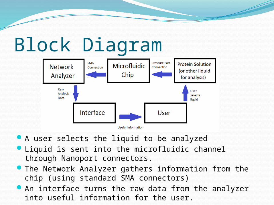
Block Diagram
A user selects the liquid to be analyzed Liquid is sent into the microfluidic channel through Nanoport connectors. The Network Analyzer gathers information from the chip (using standard
SMA connectors) An interface turns the raw data from the analyzer into useful information
for the user.

Alternate ConceptsUsing acrylic instead of PCB material.Using a waveguide perpendicular to the microfluidic
channel rather than parallel.Using a multilayer board to build the waveguide
without direct contact to the channel. Modifying the geometry of the channel and reservoirs
and having the waveguide go straight across the chipMaking the waveguide run over the top of the channel
on the main copper layer.Using vias to avoid the 90 degree angle turns in the
copper lines. Using Prepreg to ensure no leakage.

Fundamental Design Issues
Material Selection: Decide what PCB type material will be optimal for our system.
Leakage Prevention: Design the board so that the protein solution can be confined properly to the channel.
Signal Path Geometry: Consider how to align the channel and waveguide and how to fit all the connections on the board.

Illustrations
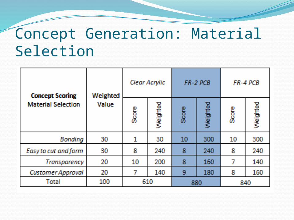
Concept Generation: Material Selection

Concept Generation: Leakage Prevention

Concept Generation: Signal Path Generation
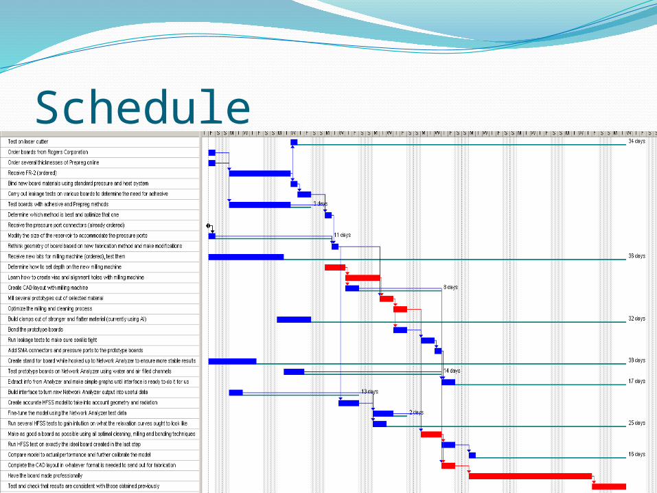
Schedule

Schedule – Critical PathDetermine how to
set milling depth on machine
Learn how to create vias and alignment holes
Make several prototypes
Have board made professionally

Schedule – CategoriesFirst category: learning how to use the devices and
software.Kyra – HFSS (modeling software), interfaces computerMatthieu – milling machine, CAD software , how to
create the boardsSecond category: physically creating the board
It takes time to bond the board, run leakage tests, and create several prototypes
Third category: waiting for outside sourcesArrival of parts, making the chip professionallyWe have little control over this category so we need to
order early

Current & Future WorkKyra is fine-tuning the current HFSS model.We will soon be getting the Prepreg and
running several tests to optimize bonding.Still learning how to use the camera system
on the milling machine.Using Network Analyzer to run preliminary
tests and gain intuition.
By next design review:All fabrication issues finalized and
optimized.Have a complete working model of our
system in HFSS.