fire tests on loaded cross-laminated timber wall … · fire tests on loaded cross-laminated timber...
TRANSCRIPT

Fire Tests on Loaded Cross-laminated Timber Wall and Floor Elements
MICHAEL KLIPPEL, CLAUDE LEYDER, ANDREA FRANGI, and MARIO FONTANA Institute of Structural Engineering, ETH Zurich Wolfang-Pauli-Strasse 15 8093 Zurich, Switzerland FRANK LAM Department of Wood Science, University of British Columbia 2424 Main Mall Vancouver, British Columbia, Canada V6T 1Z4 ARIO CECCOTTI Trees and Timber Institute CNR-IVALSA 38010 San Michele all'Adige (TN), Italy
ABSTRACT
Cross-laminated timber (CLT) panels are relatively new engineered wood products that can be used as load
bearing walls, floors and roof elements in innovative and high quality modern timber structures. The fire
behavior of cross-laminated timber panels requires careful evaluation to allow the expansion of CLT
elements usage in buildings. A University of British Columbia study has been conducted at the Trees and
Timber Institute CNR-IVALSA in San Michele all’Adige, Italy to experimentally evaluate the fire
performance of Canadian CLT panels. In total, ten loaded fire tests were performed using standard fire
curves (ULC/ASTM and ISO) to study the influence of different cross-section layups on the fire resistance
of floor and wall elements and to investigate the influence of different anchors on the fire behavior of wall
elements. This paper presents the main results of the experimental analyses and discusses in particular the
charring rate, one of the main parameters in fire design.
KEYWORDS: cross-laminated timber, fire tests, fire behavior, one-dimensional charring, structural
response, structural design
NOMENCLATURE LISTING
dchar charring depth (mm) Greek MR,d,fi design bending resistance in fire (kNm) 0 one-dimensional charring rate (mm/min)
Md,fi design bending moment in fire (kNm)
T temperature (°C)
t time (min)
fc,m mean compression strength (N/mm2)
INTRODUCTION
Cross-laminated timber (CLT) is a timber product composed of simple softwood boards, between 10 and
40 mm thick and 80 to 240 mm wide. The variety of cross-section layups is very large. The number of plies
ranges from 3 to 7, or even 9 and the thicknesses of the different layers can be identical or varied. The main
difference to glued-laminated timber beams is that the orientation of the layers is crosswise. The result is a
two dimensional structural system, which can carry loads in longitudinal and transversal direction.
Therefore, CLT can be used as floor, roof and wall elements. In common practice, the bottom layer and the
top layer are oriented parallel to the long axis of the panel with a symmetrical cross-sectional layup (see
Fig. 1).
Over the past few years, timber structures have started to regain in market share, not only thanks to the so-
called green image but also because of their high quality and economy. As one of the newer wood products
CLT stands for innovation and quality. Indeed, CLT heavy timber constructions offer many advantages,
including good thermal and structural performance. Also in terms of economic factors, CLT can be
competitive. In North America, where the low-rise building sector is dominated by light frame wood
construction, government and industry see the potential of CLT in mid- and medium rise buildings. In
FIRE SAFETY SCIENCE-PROCEEDINGS OF THE ELEVENTH INTERNATIONAL SYMPOSIUM pp. 626-639 COPYRIGHT © 2014 INTERNATIONAL ASSOCIATION FOR FIRE SAFETY SCIENCE/ DOI: 10.3801/IAFSS.FSS.11-626
626

Sweden, UK and Italy buildings of CLT with 7 to 9 storeys have been erected. An important attribute of
CLT constructions is the fast and industrialized production process, as well as the very short
assembly/construction time, which is due to simple connection details. In order to allow the expanded use
of CLT panels in high quality wood constructions, issues related to the fire resistance of this new structural
system need to be studied in detail so that engineers and architects can specify the product with full
confidence.
Fig. 1. Sketch of a cross-laminated timber panel.
The fire behavior of timber buildings has been a major concern for long time, especially as the structural
system is made of combustible material. Through the formation of a protective charcoal layer, the inner
part of a timber member is naturally protected from high temperatures. Nowadays, timber structures can
fulfill the specifications of national fire resistance codes for low-rise buildings equally well as any other
type of structural system. In terms of mid-rise buildings, most countries still have a rather restrictive policy
for timber structures and quite often special measures, like gypsum claddings or sprinkler systems have to
be installed. Nonetheless, the fire performance of timber structures can be just as good as the performance
of a steel or concrete structure. Building codes have only recently started changing their concept to a more
performance based approach, where structures will be evaluated fairly in terms of their actual performance
in a fire situation. Therefore, more knowledge about the actual behavior of timber structures under fire
conditions is useful and has become a common research topic.
As far as the fire performance of CLT is concerned, the reduced amount of cavities, compared to light-
timber frame structures, prevents the propagation of the fire. However the total fire load is increased, as the
amount of combustible material is higher. Another aspect is the fire performance of the adhesive. For solid
timber members under fire load, the protective charcoal layer is very important, as it assures low
temperatures in the inner part of the timber members and, therefore, retaining enough load-carrying
capacity of the remaining cross-section. For CLT, the charcoal layers might fall off, as the single boards are
held together by adhesive only. However, falling off of the layers does not necessarily mean that the
assembly (e.g. the depth of the panel) is influenced by the fire design. Design of CLT is usually based on
the verification of deformations and vibrations. Further, it might be appropriate to distinguish between
walls and floors, since tests performed on walls did not show falling off of the layers.
In recent years, experimental studies have been carried out to investigate the fire performance of cross-
laminated solid timber panels. Small specimens were subjected to fire [1,2,3,4], but also large- [2,5,6,7,8]
and full-scale fire tests [9] were performed. Also in Canada fire tests on CLT panels were carried out
[10,11]. In the following, a brief overview of these tests is given and the main outcome with respect to the
fire resistance of cross-laminated solid timber panels is presented.
In 2007, a first testing series was carried out to analyze the question if the behavior of CLT under fire
conditions is similar to the behavior of solid wood [2]. The small horizontal furnace at EMPA in
Duebendorf, Switzerland was used to test a series of unloaded small-scale specimens, consisting of a
massive timber panel and a 3-layered timber panel, to allow for direct comparison. The specimens were
either 54 mm thick or two specimens of 27 mm thickness were put on top of each other, whereas the 3-
layered panel consisted of 18 mm and 9 mm thick layers. Polyurethane adhesive was used to bond the plies
of the 3-layered panel. The specimens were subjected to the standard ISO temperature fire curve [12]. The
results of the analysis showed that the fire behavior of cross-laminated solid timber panels depends on the
behavior of the single layers. If the charred layers fall off, an increased charring rate needs to be taken into
FIRE SAFETY SCIENCE-PROCEEDINGS OF THE ELEVENTH INTERNATIONAL SYMPOSIUM pp. 626-639 COPYRIGHT © 2014 INTERNATIONAL ASSOCIATION FOR FIRE SAFETY SCIENCE/ DOI: 10.3801/IAFSS.FSS.11-626
627
account for their design. The same effect is observed for initially protected timber members after the fire
protection has fallen off. It was observed that the initial charring rate of the second layer after falling off of
the charred layer was about twice as high until a charcoal layer of sufficient thickness had developed again.
Thus, the fire behavior of cross-laminated solid timber panels can be strongly influenced by the thickness
and the number of layers. CLT with thicker outer layers has a more favorable behavior in fire than CLT
with thinner layers as the falling off occurs at longer time intervals. Further, vertical structural members
(walls) may show a better fire behavior in comparison to horizontal members (floors).
Another project carried out in 2006, called SOFIE, shows the favorable behavior of a massive CLT timber
construction [9]. A natural full-scale fire test of a three stories CLT building was carried out in Tsukaba,
Japan to check the global performance and find possible weaknesses of the timber structure. The cross-
laminated solid timber panels were protected by one or two layers of non combustible gypsum
plasterboards. The test confirmed that with pure structural measures it is possible to limit the fire spread to
one room even for timber structures. In the room above the fire compartment no elevated temperatures
were measured and no smoke was observed. Further, by protecting the timber structure with gypsum
plasterboards the damage of the cross-laminated solid timber panels was relatively small.
Within the framework of the project SOFIE, two single walls were tested at the Trees and Timber Institute
(CNR-IVALSA) in San Michele all’Adige, Italy [2]. The tests were performed without loading using the
standard ISO temperature fire curve [12]. The cross-sections were 84 mm and 85 mm thick, whereas the
first was a 3 ply element (3 x 28 mm) and the second a 5 ply element (5 x 17 mm). Polyurethane adhesive
was used. The measured charring rates were 0.64 and 0.68 mm/min, and hence in the range of the charring
rate for solid wood. There was no difference between the two tests, although the thickness and the number
of layers were different. No falling off of the layers was observed. Thus, the panels performed like solid
wood panels.
A PhD-thesis, recently completed at the University of Cagliari studies the fire resistance of CLT
(respectively XLAM) panels [7]. Three five-layer XLAM panels were tested in a horizontal furnace
(3 m x 5 m) at the Trees and Timber Institute (CNR-IVALSA) in San Michele all’Adige, Italy. The aim of
these tests was to investigate the fire resistance of such panels. Loaded and unloaded as well as initially
protected and unprotected fire tests on XLAM panels were performed. The cross-section was the same as
for the tests carried out by Schmid et al. and Wilinder [1,3]. The panels were 150 mm deep and consisted of
five layers (42-19-28-19-42 mm) that were face glued crosswise. The boards were finger jointed in
longitudinal direction and the adhesive used for finger jointing and face gluing was polyurethane. The
charring rate for the unprotected panels was similar to the value proposed by Eurocode 5 [13] for solid and
glued laminated timber under one-dimensional fire exposure (0.65 mm/min). For the initially protected
panels, a one-dimensional charring rate of about 1 mm/min was obtained. This value is higher than those
observed in the tests with unprotected panels, since after the cladding has fallen off an increased charring
rate occurs due to the increased fire temperature. In contradiction to the research work by Frangi et al. [4],
no significant falling off of charred layers was observed.
One large-scale test on a timber slab was carried out at the horizontal furnace (3 m x 4.85 m) at EMPA,
Switzerland [2]. The test results permit the analysis of the behavior of the 3-layered timber panels (with
3x9 mm thick layers). The temperature was measured directly above the timber cladding and the charring
rate was calculated to 1.0 mm/min. This leads to the same conclusion as for the previously described small
scale horizontal tests that the falling off of charred layers leads to a higher charring rate than the one-
dimensional charring rate for solid timber panels.
In order to acquire more knowledge about the influence of the thickness and the number of layers as well as
the fire performance of the adhesive in the glueline on the fire resistance, another testing series was carried
out by Frangi et al. [4]. The CLT panels were produced using 5 different types of polyurethane adhesive
(PUR) and one type of melamine-urea-formaldehyde adhesive (MUF). The following layer thicknesses
were used: 10, 20 and 30 mm. The total thickness of all panels was equal to 60 mm. For one specimen the
layers were all oriented parallel instead of crosswise, to study the influence of the layer orientation. The
tests were carried out on the small-scale furnace (1.0 m x 0.8 m) at EMPA in Duebendorf, Switzerland
without load, using the standard ISO temperature fire curve [12]. Thermocouples were placed between the
different layers to record temperatures. The results of the fire tests showed that the fire behavior of cross-
laminated timber panels is influenced by the behavior of the adhesive in the glueline between the panels.
FIRE SAFETY SCIENCE-PROCEEDINGS OF THE ELEVENTH INTERNATIONAL SYMPOSIUM pp. 626-639 COPYRIGHT © 2014 INTERNATIONAL ASSOCIATION FOR FIRE SAFETY SCIENCE/ DOI: 10.3801/IAFSS.FSS.11-626
628

For the MUF specimens the charring rate was constant and equal to the one-dimensional charring rate of
solid wood. The charring rates for all PUR glued specimens are quite similar for all 5 ply (around
1.0 mm/min) and 3 ply specimens (around 0.85 mm/min). This shows that the number and the thickness of
the layers have a significant influence on the fire behavior of CLT, in the case that the charred layers fall
off. If the charred layers remain in place, the charring rate remains constant and there is no influence of the
number and thickness of the layers. As already investigated in previous tests, thicker layers (3 ply) showed
a better fire performance than thinner layers (5 ply). The orientation of the layers showed no particular
influence on the fire performance.
At SP Trätek Institute in Sweden, 30 fire tests have been carried out [1,3] on 150 mm wide cross-laminated
solid timber specimens. Two different 5 ply cross-sections were tested (5 x 19 mm and 42-19-28-19-42
mm), where the two outer and the middle layer are oriented in longitudinal direction and the two other
layers are oriented crosswise. Half of the specimens were tested with the compression side exposed to fire
and the other half with the tension side exposed to fire. Both, for members with the compression side
exposed to fire and with the tension side exposed to fire, a charring rate similar to solid wood was
observed.
The charring rates of CLT exposed to different time-temperature curves were analyzed by Friquin et al. [5].
Three tests without loading were performed using a large-scale horizontal furnace (opening 3 x 4 m). A
melamine-urea-formaldehyde adhesive was used in the bondline between the layers. All specimens had
7 layers and different total depths to enable comparison of the charring rate for different panel thicknesses.
The charring depth was calculated via thermocouple measurements, placed at 10 mm intervals inside the
panels. It was assumed that the wood is completely charred at a temperature of 300°C. The resulting
charring rates vary considerably from 0.31 to 0.95 mm/min. It was concluded that the heating rate and the
maximum temperature of the fire curves have an influence on the charring rate. It is worth noting that the
charring rate using the standard ISO temperature fire curve after 60 minutes of fire exposure was between
0.45 and 0.68 mm/min. No falling off of the layers was observed in all tests.
In Austria, a comprehensive research study on initially protected and unprotected CLT panels was
performed [6]. 3 and 5 ply CLT panels were tested with a total depth ranging from 78 to 150 mm. Large-
scale fire tests using the standard ISO temperature fire curve [12] on loaded CLT wall and floor panels
were performed. In these tests, for the first layers in the wall tests, an average charring rate of 0.61 mm/min
and for the floor elements of 0.65 mm/min was determined. On average, a charring rate of 0.69 mm/min
(walls) and 0.71 mm/min (floors without falling off of the layers) was measured. In two tests on floor
panels, an increased charring of about 1.5 mm/min for the second layer was observed due to falling off of
the first layer.
Recently, two full-scale load-bearing wall tests with CLT have been conducted at the SP Trätek facility in
Sweden [8]. The walls were 3 ply CLT panels with a total thickness of 82 mm
(19-44-19 mm). Both walls were protected with a gypsum cladding, for the first wall a 12.5 mm thick
gypsum board type A and for the second wall a 15 mm thick gypsum board type F was used. Between the
claddings and the CLT walls thermocouples were installed. The specimens were loaded with 10% of their
load-bearing capacity at normal condition. The fire resistance of the wall initially protected with a gypsum
board type A was 40 minutes and the wall with a gypsum board type F held the load during 60 minutes.
The type A gypsum board fell off after about 30 minutes and the charring rate measured was 0.89 mm/min.
For the second wall, with the gypsum board F, the protection did not fall off, and the measured charring
rate corresponds to 0.58 mm/min.
In Canada, the use of CLT in buildings started in recent years. Small-scale tests have been carried out by
FPInnovations [10]. The Canadian testing standard for fire endurance [14] has been applied to determine
the charring rates and the behavior of CLT elements. Six vertical fire tests on 1.2 m by 1.2 m elements have
been conducted. Half of the tested panels were bonded using a Phenol-resorcin-formaldeyde (PRF)
adhesive and the other half using polyurethane (PUR) adhesive. All panels were 3 ply elements with a total
thickness of 144 mm (3 x 38 mm). The protection by North American gypsum boards type X was also
studied, by protecting some of the panels with a 15.9 mm or with two 12.7 mm thick boards.
Thermocouples were installed in-between the layers. No load was applied and all panels were tested until
integrity failure occurred. The failure times range from 58 to 210 minutes. A large difference exists
between the PRF and the PUR panels. Indeed PUR tends to fill up gaps by foaming during the
FIRE SAFETY SCIENCE-PROCEEDINGS OF THE ELEVENTH INTERNATIONAL SYMPOSIUM pp. 626-639 COPYRIGHT © 2014 INTERNATIONAL ASSOCIATION FOR FIRE SAFETY SCIENCE/ DOI: 10.3801/IAFSS.FSS.11-626
629
manufacturing process, whereas for the PRF boards larger air gaps remain in-between the boards.
Therefore, the fire could spread easily through the panels, amplified because of the pressure difference
between the furnace and the ambient air. This led to very early integrity failures. The average charring rates
were calculated based on the thermocouples temperature recordings and range from 0.48 mm/min to 0.62
mm/min. These values are even lower than the one dimensional charring rates given by the Eurocode 5 [13]
and the National Design Specifications of the United States [15]. The gypsum boards started cracking after
around 50 minutes and fell off after about 100 minutes. All these time values agree well with the values
based on the Eurocode 5 [13] predictions. The non-edge-glued polyurethane panel reached a 4 minutes
longer failure time than the edge-glued panel, which can be explained by the way the charcoal falls off. For
the edge-glued panel, the charcoal layer fell off all at once and for the non-edge glued panel the charcoal
layer fell off in pieces, leading to a longer protection time.
In a following project at FPInnovations, eight full-scale tests were performed [11]. The assemblies tested
consisted of three wall and five floor tests and were subjected to the standard ULC S101 fire exposure [14].
Each panel had a width of 763 mm. The floor panels were 4786 mm and the wall panels were 3048 mm
long. The plies were glued together with a polyurethane (PUR) adhesive, which fulfils the CSA O112.10
standard [16]. The tests were carried out in the NRC’s (National Research Council) floor and wall furnaces.
Three or five ply CLT panels were tested. Some of the CLT panels were fully exposed to fire (unprotected)
while some panels were initially protected by Type X gypsum board. The panels were subjected to a
constant loading during the test, which was determined based on the L/240 deflection criterion and the
load-carrying capacity, respectively. In the tests, significant fire resistance of about three hours was
achieved under full loading conditions. Either integrity or structural failure was observed as failure mode.
By means of thermocouple measurements in the cross-section between the CLT plies, the temperature
distribution during the fire tests was recorded. The overall average charring rate based on these
measurements was between 0.41 and 0.80 mm/min. Osborne et al. [11] concluded that an overall charring
rate of 0.65 mm/min can be assumed.
Based on the various test results presented above, it can be concluded that the fire resistance of cross-
laminated solid timber panels depends upon several parameters such as the number and thickness of layers,
the use as floor or wall component and the adhesive in the bondline between the different layers. In the
following section, a University of British Columbia project to evaluate the fire response of different CLT
panels in full scale fire tests performed at CNR-IVALSA is presented. In these fire tests, the influence of
different cross-section layups was studied for CLT floor and wall elements from British Columbia, Canada.
Further, the influence of two different bottom fixations for wall elements was investigated. In the final
section of this paper, the results are compared to a proposed charring model by Frangi et al. [2] to account
for falling off of the charred layers in the fire design. This section also investigates the influence of falling
off of charred layers during a fire on the assembly of a CLT panel.
The fire tests presented in here were performed as collaboration between the Department of Wood Science
at University of British Columbia, Canada and the Trees and Timber Institute CNR-IVALSA, Italy. The
project was further accompanied by the Institute of Structural Engineering of ETH Zurich, Switzerland.
FIRE TESTS
The test specimens consisted of timber panels made of Spruce-Pine-Fir (SPF) lumber as classified in [17].
In British Columbia the lodegpole pine (Pinus contorta) species represents the majority of the SPF lumber
production wood. The boards used to produce the CLT specimens were classified as kiln dried No. 2,
which is similar to timber strength class C16 according to EN 338 [18].
One of the main objectives of the current study is to analyze the influence of different cross-section layups
on the fire behavior of the CLT panels. Therefore, three different cross-sections were manufactured (see
Table 1). The 3 ply cross-section consists of three boards with a thickness of 34 mm each, leading to a total
thickness of 102 mm. For the 5 ply cross-section, a strong version and a weak version were manufactured.
The strong version (abbreviated as SR) consisted of four plies in longitudinal direction and one crosswise
ply in the center of the cross-section, with the following thicknesses: 34-24-24-24-34 [mm]. The weak
version (abbreviated as WR) has three plies in longitudinal direction (the two outer plies and the middle
ply, each 34 mm thick) and two plies oriented crosswise (each 19 mm thick). The total thickness of the
5 ply panel is 140 mm for both the SR and WR versions. It is assumed that the (p)arallel/(c)rosswise/p/c/p
FIRE SAFETY SCIENCE-PROCEEDINGS OF THE ELEVENTH INTERNATIONAL SYMPOSIUM pp. 626-639 COPYRIGHT © 2014 INTERNATIONAL ASSOCIATION FOR FIRE SAFETY SCIENCE/ DOI: 10.3801/IAFSS.FSS.11-626
630

version will have a lower bending strength out of plane and, therefore, this cross-section is designated as
the “weak resistance (WR)” layup. The p/p/c/p/p should have a higher bending strength out of plane and is
therefore designated as the “strong resistance (SR)” layup. For the wall tests, two different support types
were designed. One is a T-shape steel connector slotted into the CLT element and fixed with dowels, called
SC for strong connection. The second support type consists of two angle brackets, fixed with nails to the
CLT element, herein designated as the weak connection (WC). The SC support should have a higher
resistance against out of plane bending than the WC. The floor panels were tested in 4-point bending tests,
where the load was applied in two points, hence the designation 2P. In total, four tests were performed on
floor elements with different connection and load level ((see Table 1).
Table 1. Overview of the fire test set-ups.
Type No of
plies Orientation
a Panel thickness
[mm]
Thickness of
layers [mm]
Information on
support, load Designation
b
Wall 3 p/c/p 102 34-34-34 T-support
(3.34MPa) W-3P-SC
Wall 3 p/c/p 102 34-34-34 L-support
(3.34MPa) W-3P-WC
Wall 5 p/c/p/c/p 140 34-19-34-19-34 T-support
(3.06MPa) W-5P-WR-SC
Wall 5 p/c/p/c/p 140 34-19-34-19-34 L-support
(3.06MPa) W-5P-WR-WC
Wall 5 p/p/c/p/p 140 34-24-24-24-34 T-support
(2.69MPa) W-5P-SR-SC
Wall 5 p/p/c/p/p 140 34-24-24-24-34 L-support
(2.69MPa) W-5P-SR-WC
Floor 5 p/c/p/c/p 140 34-19-34-19-34 2P (F=14.6kN) F-2P-WR-1
Floor 5 p/c/p/c/p 140 34-19-34-19-34 2P (F=18.4kN) F-2P-WR-2
Floor 5 p/p/c/p/p 140 34-24-24-24-34 2P (F=16.8kN) F-2P-SR-1
Floor 5 p/p/c/p/p 140 34-24-24-24-34 2P (F=21.2kN) F-2P-SR-2 a p stands for parallel orientation of the layers, c for crosswise orientation
b (W)all or (F)loor element, 3 or 5 (P)lies, (W)eak or (S)trong (R)esistance (see orientation of the layers),
(W)eak or (S)trong (C)onnection
Before the production process, each board was tested to determine its elastic modulus (MOE). A
Metriguard Model 340 Transverse Vibration E-Computer was used to conduct a non-destructive dynamic
test. In addition to the modulus of elasticity, the exact board dimensions were recorded. Table 2 shows a
summary of the measurement results. The mean moisture content of the boards was 12% when the MOE
was determined. All boards were of sufficient length for the CLT production and thus no finger jointing
was necessary. The panels were produced according to the Standard for Performance-Rated CLT [19] by
CST Innovations. The boards were bonded with a polyurethane adhesive (PUR) certified according to
ASTM D7247 [20] for the use in structural timber elements.
Table 2. Summary of the vibration MOE tests.
2x4 SPFa, Length = 5500 mm 2x4 SPF
a, Length = 4285 mm
Width [mm] Depth [mm] MOE [Gpa] Width [mm] Depth [mm] MOE [Gpa]
Avg. 137.87 37.65 11.36 138.94 38.31 10.66
Stdev. 5.79 0.47 1.81 1.10 1.55 2.09
COV 0.04 0.01 0.16 0.01 0.04 0.20
Count 480 480 480 435 435 435 a SPF stands for Spruce-Pine-Fir, the species combination to which lodgepole pine is attributed according to the
Canadian Code [17].
The wall elements tested had a width of 660mm (for 5ply) or 480mm (for 3ply) depending on the CLT
panel thickness. Hence, the testing wall was composed of three pieces; the CLT test specimen in the middle FIRE SAFETY SCIENCE-PROCEEDINGS OF THE ELEVENTH INTERNATIONAL SYMPOSIUM pp. 626-639 COPYRIGHT © 2014 INTERNATIONAL ASSOCIATION FOR FIRE SAFETY SCIENCE/ DOI: 10.3801/IAFSS.FSS.11-626
631

and two unloaded side pieces, which were protected by non-combustible material (see Fig. 2a). Between
the pieces, insulation guaranteed a one-dimensional heat transfer. For the wall tests, the load-level was
chosen based upon the load-carrying capacity on the bottom rail of the wall, as this is the governing design
case (compression perpendicular to the grain) for this type of assembly (wall-floor assembly). The load-
carrying capacity was calculated according to the Canadian Code [17]. During the fire test, the total load of
150 kN was evenly distributed via a steel beam. This load corresponds to the stresses given in Table 1 for
the specimens.
(a) (b) (c)
Fig. 2. Test-setup for wall fire tests showing details of the weak and strong connection assembly. (a) Wall
test setup. (b) L-brackets (weak connection). (c) T-bracket (strong connection).
Two different supports were tested in the wall tests. The weak support version was assembled using L-
brackets as shown in Fig. 2b. The strong support version was assembled using a T-bracket as illustrated in
Fig. 2c. Compared to the L-bracket system, the T-bracket support was expected to provide a higher moment
resistance against bending at the base of the wall. For each support, three fire tests were performed. The
wall panels were fastened to the ground and to the top floor with L-brackets. Only for the loaded middle
part of the strong connection wall (SC), a T-bracket was inserted into a pre-sawed slot in the CLT-panel
(see Fig. 2c). In order to avoid failure in the connection, the support area was covered with gypsum board.
So far, most full-scale fire tests on CLT walls have not considered the influence of the support on the fire
performance. The walls were usually attached at the borders of the furnace, so that the connection was
outside the furnace and not exposed to fire. Indeed, the main objective of this research project is not to
analyze the fire performance of the connection itself, but to study the influence of the support type on the
wall deflection under thermal load. Thus, in order to limit the number of parameters influencing the results,
extra heat transfer through the steel elements and softening of the steel should be avoided. Therefore, the
steel elements were protected by gypsum board of sufficient thickness to ensure thermal protection (see
Fig. 2 b,c).
FIRE SAFETY SCIENCE-PROCEEDINGS OF THE ELEVENTH INTERNATIONAL SYMPOSIUM pp. 626-639 COPYRIGHT © 2014 INTERNATIONAL ASSOCIATION FOR FIRE SAFETY SCIENCE/ DOI: 10.3801/IAFSS.FSS.11-626
632

L=4.8m
F/2 F/2
L/3L/3
Fig. 3. 4-point bending test set-up for the floor fire tests.
For the floors, it was assumed that the maximum deflection criterion according to [17] of L/240 governs the
load-carrying capacity. The span of the floors between the supports was 4.8 m (see Fig. 3). The width of the
floor panels was chosen to be 1.2 m because of manufacturing and shipping limits. The rest of the furnace
area was closed with side panels. For the 4-point-bending test, the calculated total loads F are 14.6 kN for
the weak layup (p/c/p/c/p) and 16.8 kN for the strong layup (p/p/c/p/p). Half of this load was applied at
each of the two loading points.
For all tests, the deflections of the specimen were recorded. For the wall tests, the deflection was measured
at three points (LVDT 1-3 in Fig. 2 a). During the floor tests, the deflection was measured at midspan.
RESULTS
Fire tests on wall elements
In total, six wall elements were tested with the ULC/ASTM standard fire curve [21]. Table 3 shows a
summary of the test results. Fire time is the time where the tests had to be stopped because of integrity
failure between the loaded and the unloaded panels. No integrity failure of the panel itself was observed.
After that time the wall panel was moved away from the furnace and the fire was quickly extinguished.
After the panel had cooled down, the remaining thickness of the cross-section was measured at mid-height
each 15 mm. The charring depth dchar [mm] and the one-dimensional charring rate [mm/min] could then
be derived. During the tests, vertical and horizontal deflections were measured. Table 3 shows that the
mean one-dimensional charring rate calculated on the basis of the residual cross-sections, in all wall
tests was only slightly higher than the one-dimensional charring rate of solid wood (0.65 mm/min) given in
Eurocode 5 [13]. The vertical deflection progressed in all tests more or less linearly over time (Table 3 and
Fig. 4a). The vertical deflections remain very small even though the load-bearing cross-section of the wall
was reduced by at least 30% during the fire test.
It has to be noted that the load level of 150 kN corresponds to a compressive stress of about 3 MPa in the
load-bearing (parallel) boards, which is about 12% of the mean compressive strength fc,m of a regular
softwood timber element. Fig. 4b shows the horizontal deflection recorded at mid-height of the wall (see
Fig. 2a, LVDT-2). The horizontal deflection is influenced by thermal expansion, the increasing stress on
the remaining cross-section and the increasing eccentricity of the applied load. In the first phase of the fire
tests, the wall deflects slightly in the direction of the fire exposed side. Later, it is not possible to clearly
describe the behavior in terms of deflection. Therefore, the influence of any of the studied parameters on
the deflection behavior of the wall cannot be given without contradiction.
Table 3. Test results of fire tests on CLT wall panels.
Test name Fire timea [min] dchar [mm] [mm/min] Max vertical deflection [mm]
W-3P-SC 100 63.7 0.64 9.6
W-3P-WC 88 63.0 0.72 10.0
W-5P-SR-WC 100 73.6 0.74 2.1
W-5P-SR-SC 89 66.1 0.74 6.3
W-5P-WR-WC 97 74.3 0.74 8.3
W-5P-WR-SC 100 72.5 0.73 9.1 a No failure, only integrity failure in-between the panels occurred.
FIRE SAFETY SCIENCE-PROCEEDINGS OF THE ELEVENTH INTERNATIONAL SYMPOSIUM pp. 626-639 COPYRIGHT © 2014 INTERNATIONAL ASSOCIATION FOR FIRE SAFETY SCIENCE/ DOI: 10.3801/IAFSS.FSS.11-626
633

0 20 40 60 80 100 120Time [min]
0
2
4
6
8
10
12
14Vertical deflection [mm]
W-3P-WC
W-5P-WR-WC
W-5P-SR-WC
W-3P-SC
W-5P-WR-SC
W-5P-SR-SC
x
(a)
0 20 40 60 80 100 120Time [min]
-25
-20
-15
-10
-5
0
5
10
15
20
25Horizontal deflection (LVDT 2) [mm]
W-3P-WC
W-5P-WR-WC
W-5P-SR-WC
W-3P-SC
W-5P-WR-SC
W-5P-SR-SC
Exposed side
x
+-
(b)
Fig. 4. Vertical (a) and horizontal (b) deflection of the walls.
As the tests were stopped before structural failure occurred, no conclusions about the fire resistance of the
walls can be drawn. The walls reached at least a fire resistance of 88 minutes at the stopping point of the
fire test.
Fire tests on floor elements
Four floor tests were carried out on the horizontal furnace at CNR-IVALSA, using the standard ISO
temperature fire curve [12]. All tests on floor elements were performed as 4-point-bending tests, whereas
the load was slightly varied. Table 4 gives an overview of the fire test results on the CLT floor panels. The
tests were stopped after one hour, as the goal was to measure the charring rates and deflections and not to
determine the fire resistance time. At the end of the test, the load was first removed, the panels were lifted
from the furnace and the fire was extinguished. After the panels had cooled down the thickness of the
remaining cross-section was measured and the mean charring rate calculated. The charring rates were in the
range of 0.75 to 0.81mm/min. and were greater than the one-dimensional charring rate indicated by the
Eurocode 5 [13]. The vertical deflection was measured with LVDT’s at the unexposed surface at midspan
(Table 4 and Fig. 5).
Table 4. Test results of fire tests on CLT floor panels.
Test Name Fire Time
a
[min]
Load
[kN]
dchar
[mm]
β0
[mm/min]
Max vertical deflection
[mm]
F-2P-WR-1 67 14.6 54.5 0.81 55.5
F-2P-WR-2 57 18.4 46.2 0.81 67.7
F-2P-SR-1 67 16.81 50.5 0.75 63.4
F-2P-SR-2 57 21.2 45.5 0.80 76.2
a No failure, stop of the fire test due to safety reasons.
The deflection at midspan increased with the time of fire exposure. The measurement devices were
removed before the fire test was stopped. As the fire progresses the cross-section is reduced, leading to
higher stresses in the residual cross-section and hence higher deflections. The deflections were not
FIRE SAFETY SCIENCE-PROCEEDINGS OF THE ELEVENTH INTERNATIONAL SYMPOSIUM pp. 626-639 COPYRIGHT © 2014 INTERNATIONAL ASSOCIATION FOR FIRE SAFETY SCIENCE/ DOI: 10.3801/IAFSS.FSS.11-626
634
influenced by the cross-section layup (weak resistance (WR) vs. strong resistance (SR)). However, a slight
influence of the load level was observed. In the tests with increased loading, higher deflections were
measured than in the tests with lower loading. The deflections reached maximum values of about L/75, i.e.
a value four times higher than the maximum deflection (L/240) accepted according to [17] for normal
serviceability conditions.
0 10 20 30 40 50 60 70 80Time [min]
0
10
20
30
40
50
60
70
80Vertical deflection [mm]
F-2P-WR-1
F-2P-SR-1
F-2P-SR-2
F-2P-WR-2
x
Floor
Fig. 5. Deflection at midspan against time of fire exposure for floor elements.
Comparison between wall and floor elements
The overall behavior of the wall elements and the floor elements can be compared based on the mean
charring rates (Tables 3 and 4). The mean charring rate for all wall elements corresponded to 0.72 mm/min.
For the floor elements, the mean charring rate was 0.79 mm/min. This small difference may be explained
by a higher tendency of falling off of charred layers for horizontal elements.
COMPARISON WITH SIMPLIFIED CHARRING MODEL
Based on various fire tests on CLT panels, a simplified charring model to determine the residual cross-
section for CLT has been proposed [2]. If layers are expected to fall off, the timber panel can be treated like
an initially protected timber element. After the first layer is completely charred, this layer falls off and the
second layer starts to char with twice the one dimensional charring rate until a new charcoal layer of 25 mm
thickness has been formed [2]. Then the charring rate can be reduced to the one dimensional charring rate
again until the next layer falls off. If no falling off of charred layers is expected, the same one dimensional
charring rate as for solid wood can be used for all layers. For a fire resistance of 30 minutes there will be
nearly no influence of falling off of charred layers, as only the first layer will be charred, but for a fire
rating of 60 and more minutes a clear difference in the residual cross-section is expected. However, it has
to be noted that the fire resistance of a CLT element is not linearly related to the charring rate, as the
charring of a perpendicular layer with low stiffness and strength properties, has nearly no effect on the
overall load-carrying capacity.
The charring rate for the CLT panels studied in this investigation was calculated according to the procedure
described above. Fig. 6 and Fig. 7 show the charring depth as a function of time for all fire tests performed
in comparison to the calculated charring depth according to the charring model proposed in [2]. The curves
for the calculation model assume a one-dimensional charring rate of 0.65 mm/min. Falling off of charred
layers was considered only for the floor elements. Since no information about the temperature development
between each layer was available, the graphs in Fig. 6 and Fig. 7 are shown as dotted lines. These lines do
not reflect the real behavior of the charring depth during the fire test. The following conclusions can be
drawn:
FIRE SAFETY SCIENCE-PROCEEDINGS OF THE ELEVENTH INTERNATIONAL SYMPOSIUM pp. 626-639 COPYRIGHT © 2014 INTERNATIONAL ASSOCIATION FOR FIRE SAFETY SCIENCE/ DOI: 10.3801/IAFSS.FSS.11-626
635
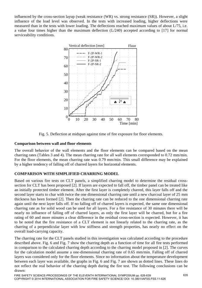
For the wall elements tested, similar charring rates were observed in all tests. The charring rates
were slightly greater than the one-dimensional charring rate for solid wood of 0.65 mm/min given
in Eurocode 5 [13].
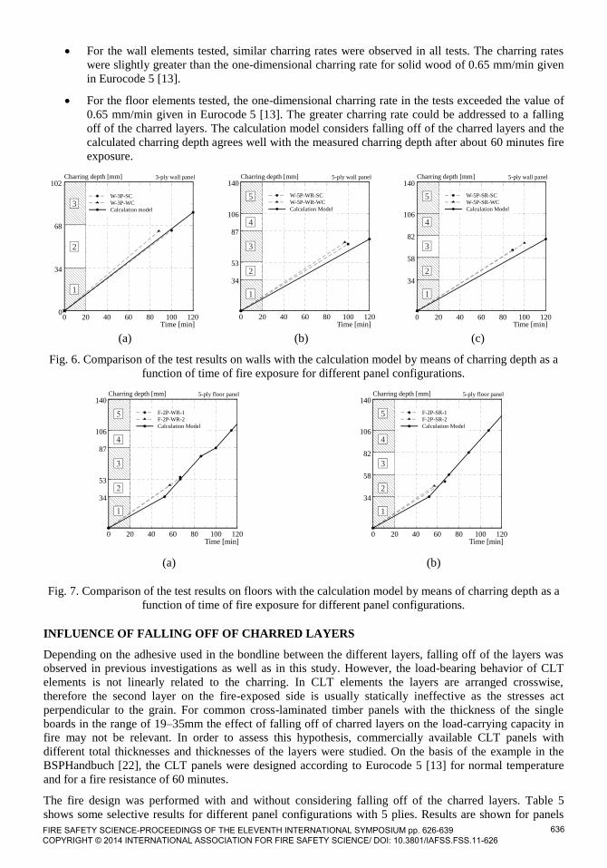
For the floor elements tested, the one-dimensional charring rate in the tests exceeded the value of
0.65 mm/min given in Eurocode 5 [13]. The greater charring rate could be addressed to a falling
off of the charred layers. The calculation model considers falling off of the charred layers and the
calculated charring depth agrees well with the measured charring depth after about 60 minutes fire
exposure.
0 20 40 60 80 100 120Time [min]
0
34
68
102Charring depth [mm] 3-ply wall panel
1
2
3W-3P-SC
W-3P-WC
Calculation model
(a)
0 20 40 60 80 100 120Time [min]
34
53
87
106
140Charring depth [mm]
W-5P-WR-SC
W-5P-WR-WC
Calculation Model
5-ply wall panel
1
2
3
4
5
(b)
0 20 40 60 80 100 120Time [min]
34
58
82
106
140Charring depth [mm]
W-5P-SR-SC
W-5P-SR-WC
Calculation Model
5-ply wall panel
1
2
3
4
5
(c)
Fig. 6. Comparison of the test results on walls with the calculation model by means of charring depth as a
function of time of fire exposure for different panel configurations.
0 20 40 60 80 100 120Time [min]
34
53
87
106
140Charring depth [mm]
F-2P-WR-1
F-2P-WR-2
Calculation Model
5-ply floor panel
(a)
0 20 40 60 80 100 120Time [min]
34
58
82
106
140Charring depth [mm]
F-2P-SR-1
F-2P-SR-2
Calculation Model
5-ply floor panel
1
2
3
4
5
(b)
Fig. 7. Comparison of the test results on floors with the calculation model by means of charring depth as a
function of time of fire exposure for different panel configurations.
INFLUENCE OF FALLING OFF OF CHARRED LAYERS
Depending on the adhesive used in the bondline between the different layers, falling off of the layers was
observed in previous investigations as well as in this study. However, the load-bearing behavior of CLT
elements is not linearly related to the charring. In CLT elements the layers are arranged crosswise,
therefore the second layer on the fire-exposed side is usually statically ineffective as the stresses act
perpendicular to the grain. For common cross-laminated timber panels with the thickness of the single
boards in the range of 19–35mm the effect of falling off of charred layers on the load-carrying capacity in
fire may not be relevant. In order to assess this hypothesis, commercially available CLT panels with
different total thicknesses and thicknesses of the layers were studied. On the basis of the example in the
BSPHandbuch [22], the CLT panels were designed according to Eurocode 5 [13] for normal temperature
and for a fire resistance of 60 minutes.
The fire design was performed with and without considering falling off of the charred layers. Table 5
shows some selective results for different panel configurations with 5 plies. Results are shown for panels
FIRE SAFETY SCIENCE-PROCEEDINGS OF THE ELEVENTH INTERNATIONAL SYMPOSIUM pp. 626-639 COPYRIGHT © 2014 INTERNATIONAL ASSOCIATION FOR FIRE SAFETY SCIENCE/ DOI: 10.3801/IAFSS.FSS.11-626
636

having a thick or thin thickness of the outermost fire exposed layer and for CLT panels with different total
thickness. Table 5 shows the quotient of the design bending moment acting on the panel in fire Md,fi and the
design bending resistance of the panel in fire MR,d,fi with and without considering falling off of the charred
layers.
Table 5. Results of fire design examples for fire exposure time of 60 minutes.
CLT-panel configuration
[mm]
24/24/24/
24/24
19/34/19/
34/19
19/44/19/
44/19
34/22/34/
22/34
35/35/35/
35/35
Thickness outermost fire
exposed layer [mm] 24 19 19 34 35
Total thickness CLT-
panel [mm] 120 125 145 146 175
Fire design with falling
off layers: Md,fi/MR,d,fi [-] 0.44 0.68 0.23 0.14 0.11
Fire design without
falling off layers:
Md,fi/MR,d,fi [-]
0.22 0.24 0.20 0.14 0.11
The examples confirmed that the fire design taking into account falling off of the charred layer is always
fulfilled (quotient Md,fi/MR,d,fi ≤ 1). For common cross-laminated timber panels and typical fire design
situations, the fire design does not govern the design of the panel configuration.
CONCLUSIONS
Large-scale fire tests on unprotected wall and floor elements of cross-laminated solid timber panels from
Canadian SPF wood were performed at CNR-IVALSA in San Michele all’Adige, Italy. A polyurethane
adhesive was used for face gluing the laminations. In the wall tests, two different types of support
conditions were studied. Further, the influence of 3 and 5 ply CLT panels with different orientation setup of
the plies on the charring behavior was studied. All tests were performed under constant loading of the
specimens. The following conclusions can be drawn:
In the wall tests, the average charring rate after about 100 minutes of fire exposure was determined
to be 0.72 mm/min, which is slightly higher than the one-dimensional charring according to EN
1995-1-2 (0.65 mm/min). This means, that the effect of falling off of charred layers is not
significant, mainly due to the quite large thickness of the layers in the range of 19 to 34mm.
No significant influence of the support conditions studied in this investigation could be observed
on the fire behavior of the CLT wall panels.
In the floor tests, the average charring rate after about 60 minutes of fire exposure was determined
to be 0.79 mm/min. The observed increased charring rate in comparison to the one-dimensional
charring according to EN 1995-1-2 (0.65 mm/min) can be attributed to the effect of falling off of
charred layers and is in agreement to tests performed in the past on floors. An influence of the
orientation of the layers on the charring behavior was not observed.
The experimental results of the floor tests were compared to a simplified charring model assuming double
charring rate for the second layer (and the subsequent layers) for the first 25 mm of depth when falling off
of the first layer occurs. The comparison shows that the calculation model can predict well the charring
depth of the floor tests performed for about 60 minutes of fire exposure. For the wall tests no falling off
was assumed for the simplified calculation model leading to slightly non-conservative results, i.e. the
measured charring depth is higher than the calculated charring depth; however, the difference is quite
small.
A parametric study showed that falling off of charred layers for common cross-laminated timber panels and
typical fire design situations has no influence on the design of the panel configuration.
FIRE SAFETY SCIENCE-PROCEEDINGS OF THE ELEVENTH INTERNATIONAL SYMPOSIUM pp. 626-639 COPYRIGHT © 2014 INTERNATIONAL ASSOCIATION FOR FIRE SAFETY SCIENCE/ DOI: 10.3801/IAFSS.FSS.11-626
637

ACKNOWLEDGMENT
The financial support received from Forestry Innovation investment BC is gratefully acknowledged. The
full collaboration received from Trees and Timber Institute CNR-IVALSA Italy under the memorandum of
understanding between the University of British Columbia and CNR IVALSA is also gratefully
acknowledged.
REFERENCES
[1] Schmid, J., König, J., and Köhler, J. (2010). Fire Exposed Cross-laminated Timber - Modeling and
Tests. In Proceedings of the 11th World Conference on Timber Engineering, Riva del Garda, Italy.
[2] Frangi, A., Fontana, M., Knobloch, M., and Bochicchio, G. (2008). Fire Behavior of Cross-
Laminated Solid Timber Panels. In Fire Safety Science - Proceedings of the Ninth international
Symposium, pages 1279–1290. http://dx.doi.org/10.3801/IAFSS.FSS.9-1279
[3] Wilinder, P. (2010). Fire Resistance in Cross-Laminated Timber, Bachelor Thesis, Jönköping
University, Jönköping, Sweden.
[4] Frangi, A., Fontana, M., Hugi, E., and Jöbstl, R. (2009). Experimental analysis of cross-laminated
timber panels in fire. Fire Safety Journal 44, p. 178-1087.
http://dx.doi.org/10.1016/j.firesaf.2009.07.007
[5] Friquin, K. L., Grimsbu, M., and Hovde, P. J. (2010). Charring rates for cross-laminated timber
panels exposed to standard and parametric fires. In Proceedings of the 12th World Conference on
Timber Engineering, Riva del Garda, Italy.
[6] Teibinger, M., Matzinger I. (2010). Basis for Evaluation of the fire resistance of timber
constructions, Final report, Holzforschung Austria, Vienna, Austria.
[7] Menis, A. (2012). Fire Resistance of Laminated Veneer Lumber (LVL) and Cross-laminated
timber (XLAM) elements. PhD thesis, Universitá degli studi di Cagliari, Italy.
[8] Gustafsson, A. (2011). Bärförmåga för treskikts korslimmad träskiva vid brand. Technical report,
SP Trätek.(in Swedish).
[9] Frangi, A., Bochicchio, G., Ceccotti, A., and Lauriola, M. P. (2008). Natural Full-Scale Fire Test
on a 3 Storey XLam Timber Building. In Proceedings of the 10th World Conference on Timber
Engineering, Miyazaki, Japan.
[10] Craft, S. T., Desjardins, R., and Mehaffey, J. R. (2011). Investigation of the Behavior of CLT
panels exposed to fire. In Proceedings of the 12th International Conference Fire and Materials.
[11] Osborne L., Dagenais C., Bénichou N. (2012). Preliminary CLT Fire Resistance Testing Report.
Point-Claire, Canada: Advanced Building Systems – Serviceability and Fire Group, 2012.
[12] ISO 834 (1999). Fire-resistance tests. Elements of building construction. Part 1: General
requirements. International Organization for Standardization, Geneva, Switzerland.
[13] EN 1995-1-2 (Eurocode 5) (2004). Design of timber structures, Part 1-2: General – Structural fire
design, CEN, Bruxelles, Belgium.
[14] CAN/ULC S101-07 (2007). Standard Methods for Fire Endurance Tests of Building Construction
and Materials. Underwriters’ Laboratories of Canada, Scarborough, Canada.
[15] NDS (2005). National Design Specification (NDS) for wood construction. American Forest and
Paper Association, Washington D.C.
[16] CSA (2010). Evaluation of Adhesives for Structural Wood Products (Milited Moisture Exposure)
(CSA O112.10-08). Canadian Standards Association, Mississauga, Ont., Canada.
[17] CSA-O86-01 (2005). Wood Design manual and CAN/CSA-O86-01 A National Standard of
Canada. Canadian Wood Council.
[18] EN 338 (2009): Structural timber - Strength classes, CEN, Bruxelles, Belgium.
FIRE SAFETY SCIENCE-PROCEEDINGS OF THE ELEVENTH INTERNATIONAL SYMPOSIUM pp. 626-639 COPYRIGHT © 2014 INTERNATIONAL ASSOCIATION FOR FIRE SAFETY SCIENCE/ DOI: 10.3801/IAFSS.FSS.11-626
638
[19] ANSI/APA PRG 320 (2011). American National Standard - Standard for Performance-Rated
Cross-Laminated Timber. APA - The Engineered Wood Association.
[20] ASTM D7247 - 07ae1 (2007). Standard Test Method for Evaluating the Shear Strength of
Adhesive Bonds in Laminated Wood Products at Elevated Temperatures, ASTM International,
West Conshohocken, PA.
[21] ASTM E119 (2012). Standard Test Methods for Fire Tests of Building Construction and
Materials, ASTM International, West Conshohocken, PA.
[22] Schickhofer, G., Bogensperger, T., Moosbrugger, T., Augustin, Blaß, Ebner, Ferk, Fontana, M.,
Frangi, A., Hamm, Jöbstl, R., Richter, Thiel, A., Traetta, G., and Uibel (2010). BSPhandbuch:
Holz-Massivbauweise in Brettsperrholz;. Verlag der Technischen Universität Graz.
FIRE SAFETY SCIENCE-PROCEEDINGS OF THE ELEVENTH INTERNATIONAL SYMPOSIUM pp. 626-639 COPYRIGHT © 2014 INTERNATIONAL ASSOCIATION FOR FIRE SAFETY SCIENCE/ DOI: 10.3801/IAFSS.FSS.11-626
639