fire response of hvac systems in multistorey buildings: an
TRANSCRIPT
ISSN 1173-5996
FIRE RESPONSE OF HVAC SYSTEMS IN MUL TISTOREY BUILDINGS: AN EXAMINATION OF THE NZBC ACCEPTABLE SOLUTIONS
BY
M J Dixon
Supervised by
Dr Charley Fleischmann
Fire Engineering Research Report 99/4 March 1999
This report was presented as a project report as part of the M.E. (Fire) degree at the University of Canterbury
School of Engineering University of Canterbury
Private Bag 4800 Christchurch, New Zealand
Phone 643 364-2250 Fax 643 364-2758

Fire Response of HVAC Systems in Multistorey Buildings: An Examination
of the NZBC Acceptable Solutions M J Dixon
Fire Engineering Research Report 99/4 March 1999
Page 1
CONTENTS
ABSTRACT .................................................................................................................. 2
ACKNOWLEDGEMENTS ............................................................................................. 3
1. INTRODUCTION ................................................................................................... 4
2. LITERATURE REVIEW ......................................................................................... 6
3. SMOKE MANAGEMENT OBJECTIVES ............................................................. 11
301 WHAT IS SMOKE? 00 ooo 0 0000000 ooooooooooooooooooooo ooooooooooOooo ooooooooooooooOOOOOOooooOoooooooo oOoOo ....... 11 302 SMOKE VOLUMESOOoo0ooooooooooOooooooOOOOOooOOOooooOooOoooooo00000oooOoooo0000°000oooooooooooooOooOoooooooooo013 303 LEAKAGE PATHS OoooooooOoOOooOOOOOoooOoOooOOOooOooooooooooooOOoooooooooooooooOOoooooooooo000oooOooOoOOOooooooo18 3.4 FIRES IN AIR CONDITIONING EOUIPMENT .. o .. o .......................................... , ........... 20
4. TYPES OF HVAC SYSTEMS .............................................................................. 22
401 AIR DELIVERY RATES .... o ... oo•····o···•oo•···o ...... o ........ o ....... o ....................... o .............. 24 4.2 UNITARY SYSTEMS ....... OOoooOOoooooooooooooooooOOOoOOo000000000oOOo00o000000oooooooooooooooooooooooooOooooo025
4020 1 Description of Unitary Systems 0 ....... 0 ......................................................... 25 4.2.2 Suitability of Unitary Systems for Smoke Control ....................................... 29
403 CENTRAL PLANT SYSTEMS ................................... 0 .......................... 0 ................. 31 4.3. 1 Description of Central Plant Systems .............. 0 .......................................... 31 403.2 Suitability of Central Plant Systems for Smoke Contro/.. ............................ 36
4.4 OTHER SYSTEMS oooo•••••••••••o•••••• ............................................................ o ............. 37
5. COMPUTER MODELLING .................................................................................. 38
5.1 BUILDINGS MODELLED ... oo••········ .. ··········•········ .. ········•oooooooooooooooooooooooooooooooooooooooo38 5.2 CONDITIONS MODELLED ............................ 0 ....................................................... 40 503 0BSERVATIONS ................... o ............................................................................. 41 5.4 CONCLUSIONS DRAWN FROM MODELLING ........................................................... 60
6. THE NZ BUILDING CODE AND THE APPROVED DOCUMENTS ..................... 53
6.1 THE DOCUMENT STRUCTURE ............................................................................. 53 6.2 VENTILATION AND SMOKE CONTROL 0BJECTIVES ............................................... 54 6.3 THE REQUIREMENTS OF THE 'ACCEPTABLE SOLUTIONS' FOR HVAC SYSTEMS ..... 56 6.4 DISCUSSION OF HVAC ASPECTS ....................................................................... 60
6.4.1 C3 Paragraph 9.6 .................................................................................... 61 6.4.2 C3 Paragraph 9. 7 ................................... 0 ............ 0 ................. 0.0 ... 0.000 ....... 62 6. 403 C3 Paragraph 7. 10 1 ................................................................................. 66 6.4.4 C2 Paragraph 8.2 ....................... 0 ............................... 0 ............................ 70
7. CONCLUSIONS .................................................................................................. 73
8. REFERENCES .................................................................................................... 76
APPENDIX A- LIST OF FIGURES ............................................................................ 80
APPENDIX 8- MODELLING RESULTS .................................................................... 81
Page 2
ABSTRACT
It is recognised that smoke is the major killer in most fires. In buildings with
mechanical heating, ventilation or air conditioning (HVAC) systems the traditional
reaction to a fire was to shut the HVAC system down, although in recent years some
buildings have included a smoke management mode as part of their HVAC system,
and/or have dedicated smoke management equipment (eg stair pressurisation).
The current Building Code Approved Documents give little guidance on the
appropriate actions for HVAC systems to take in the event of a fire, and some
requirements of the Acceptable Solutions are unclear. The objective stated in the
Approved Documents is to avoid allowing smoke to spread to other firecells via the air
conditioning system. HVAC systems can be utilised to actively manage smoke
movement and can achieve this in a variety of ways.
This report attempts to provide some improvements to the Approved Documents and
to give general guidelines to assist non-mechanical fire engineers and non-fire
mechanical engineers in designing or specifying appropriate responses to a fire in a
typical multistorey building. The report does not examine smoke control in atria or
other large spaces.
The various generic classes of ventilation or air conditioning systems are described
and the appropriate behaviour of each under fire conditions is discussed.
Results of some computer modelling of air (and cold smoke) flows around typical
buildings are presented. The modelling indicates that the current levels at which
active smoke control is invoked in the Acceptable Solutions are appropriate. It also
suggests that the frequent practice of shutting off the ventilation system on a fire
alarm may not be the best solution to managing smoke flows within the building.
Particular sections of the Acceptable Solutions relating to mechanical ventilation
which are unclear or confusing are also discussed with suggested amendments
proposed.

Page3
ACKNOWLEDGEMENTS
wish to gratefully acknowledge the following people who have given me
encouragement and assistance while I have been working on this report and during
the MEFE course as a whole.
• Firstly, Paul Taylor and the other directors of Stephenson & Turner (NZ) Ltd,
whose foresight gave me the opportunity and resources to complete the degree.
• Andy Buchanan and Charley Fleischmann for presenting the MEFE course in an
interesting and highly accessible manner, over an untested medium.
• Pat Roddick at the Canterbury University Library, who was an excellent source of
obscure articles and references from all over.
• Elizabeth Grieve at the NZ Fire Service for her generous provision of data from
their records of fire incidents.
• Paul Clements of Fire Risk Consultants Ltd who made their technical library freely
available to me.
• · Joanne Lum of S& T who managed to interpret my scribblings and converted them
into the schematic diagrams in section 4.
• All the other participants in the MEFE course, in Auckland, Wellington and
Christchurch, for the interesting discussions and debates during the course.
• And lastly and most importantly, my wife, Kerie, and sons Sean and Blair, who
have put up with me spending innumerable hours with my head in books or
pounding the computer and depriving them of a social life for several years.
Michael Dixon, February 1999
Thought for the day: "To steal ideas from one person is called plagiarism
to steal from many is called research"- Anon

Page 4
1. INTRODUCTION
It has long been recognised that the smoke and toxic gases produced during a fire are
a frequent cause of the fatalities that occur in building fires. Often the victims are in
parts of the building that are distant from the actual flaming fire, but are killed by
effects of the smoke which has migrated large distances. Control of smoke
movement is therefore vital to the safety of building occupants in the event of a fire.
The heating, ventilation and air conditioning (HVAC*) system can be an ideal means
of transporting the smoke, either intentionally or unintentionally.
By design, the HVAC system that is installed in most commercial buildings moves
large quantities of air from one part of the building to another. Air is the main
constituent of smoke and so the HVAC system can also move smoke to areas far
from the fire itself.
When operating as designed the HVAC can therefore be utilised to enhance the
safety of the building as part of an integrated smoke management system - to remove
smoke from the fire zone and discharge it safely, or to prevent smoke reaching
particular areas by providing counteracting air flows. Conversely, if the behaviour of
the HVAC under fire conditions is inappropriate it can add to the volume of smoke and
perhaps even move it to areas where the smoke endangers the building occupants.
HVAC systems are not all alike. They come in a variety of configurations and types,
and each has its own strengths and weaknesses in many aspects, including the ability
to control smoke movement.
The NZ Building Code Acceptable Solutions do not specifically address the question
of the behaviour of HVAC systems under fire conditions in a multi-storey building,
other than to note that Australian Standard AS1668.1 is an acceptable method of
compliance. A common alternative approach taken by many designers is simply to
stop the HVAC system in the event of an alarm. Which action is better? Are there
• The terms 'HVAC system' and 'Air Conditioning system' are used interchangeably in this report
Page 5
circumstances where these reactions may unintentionally allow smoke to be spread
around the building? This report discusses the various types of HVAC systems and
the appropriate response of each type to a fire alarm.
AS1668 provides a prescriptive solution that, in the event of a fire alarm, selectively
operates the HVAC plant in smoke control mode to achieve flows and pressures
which actively restricts the smoke from endangering the occupied spaces. Whilst this
may be an effective way of handling the problem with some types of systems, there
are other HVAC system types which cannot operate effectively in a smoke control
mode. There may also be solutions other than AS1668 that are equally valid under
some circumstances and with some system types.
In addition, the standard is a prescriptive document which is difficult, if not impossible,
to fully comply with in the case of a retrofit to an existing building and is inappropriate
to some system types. An understanding of the general principles of HVAC systems
and how they relate to smoke movement will assist the fire engineer in specifying
appropriate reactions to a fire event.
This report looks at the types of air conditioning and ventilation systems that are
typically found in New Zealand multi-storey buildings and assesses the appropriate
response of the various system types to a fire event, as well as making some
recommendations on aspects of specific sections of the existing Building Code
Acceptable Solutions.

Page 6
2. LITERATURE REVIEW
One of the performance requirements of New Zealand Building Code, clause C3 [BIA,
1995] states "Air conditioning and mechanical ventilation systems shall be constructed
to avoid circulation of smoke and fire between .firecel/s" (clause C3.3.7). Air
conditioning system designers must therefore make conscious and informed decisions
on the management of smoke from a fire and how the HVAC will affect the smoke
flows within the building.
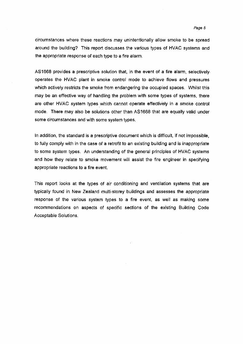
It is recognised that smoke is a major cause in fatalities in building fires. Semple
[1977] reported that over 80% of fire deaths are attributed to smoke. Often the smoke
migrates to areas remote from the actual source of the fire as has been well
documented in the fires at the MGM Grand Hotel (1980), the Roosevelt Hotel (1963)
and others [Kiote & Milke, 1992], where the majority of the fatalities occurred many
floors above the site of the fire and well away from the direct effect of the flames.
R.nlrement 24 Center Are 23 22 ~ 6 Johnson City, TN 21
II: $ Dec24,1989 20 4 ,,
J IB 2 ,,
I 18 I$
MGM Grand Hotel Fire .... 14 Deaths 8 13 Las Vegas, NV II: 12 Nov21,1980
11 10 0 II 7 10 6 ~ Roosevelt Hotel 5 Note: FlooB Renumbered for
..... B
4 Conalltency 8 7 Fire 3 II: ' Jacksonville, FL 2 5 Oec29,1963 I 4
II S 10 1 I 12 13 14 I$ 1e 17 Ill 3
Deaths 6 7 II
Deaths
Fig 2.1, Locations of deaths on upper floors where the fire was located on floor 1•
• Figure copyright 1992 by the American Society of Heating, Refrigerating and Air-Conditioning Engineers, Inc. Reprinted with permission from Klote & Milke, 1992.

Page 7
The NZ Building Code Acceptable Solutions [BIA, 1995] include a statement that
Australian Standard AS1668.1 [SAA, 1991] is an acceptable method for dealing with
HVAC systems and how they should behave under fire conditions. However, the
Acceptable Solutions do not make compliance with AS1668.1 mandatory and nor do
they directly give any alternative means of compliance. In the USA, NFPA92A [NFPA,
1993] recommends responses which are similar in principle to the Australian
Standard, although the NFPA document is not as prescriptive. There is no equivalent
New Zealand standard covering the behaviour of HVAC systems. A draft joint
AS/NZS standard [SAA/NZSA, 1996], based heavily on AS 1668.1, was issued for
public comment but was subsequently withdrawn.
The traditional reaction of the HVAC system under fire alarm conditions was to shut
the system down [Kiote, 1994; Klote & Clark, 1991, Chapman, 1983]. This reaction
has been recommended since the 1930's with the intention of preventing the spread
of smoke by the ventilation system and to stop the HVAC from feeding air to the fire.
This is still the principal reaction in many buildings today. However, having the HVAC
inoperative does not necessarily stop the smoke from migrating via the air duct
systems to other parts of the building under the influences of stack effect, buoyancy
or wind [Kiote, 1988], with the stack effect being the dominant influence [Taylor,
1982].
Semple [1977] reported that all known smoke inhalation fatalities in US and Canadian
high-rise buildings fitted with central plant HVAC had occurred when the HVAC
system was shut down.
Klote [1993] noted that stopping the air system was in part also a reaction to a 1930's
analysis that found a high proportion of building fires were located within the air
systems themselves. This problem has largely been addressed by the use of
components which are non-combustible or of limited combustibility (eg sheet metal
ducts) but any system will contain some components which are at least in part
combustible or are a source of smoke or ignition, such as electric motors, fabric air
filters and insulation. There are also alternative products being introduced into the
marketplace frequently which use non-traditional materials. However, any proposal to
use alternative materials must recognise the consequences of potentially combustible

Page 8
components in an environment where the products of any fire will be rapidly spread to
occupied areas.
The danger in not shutting down the HVAC is that, when operating as intended, the
HVAC systems mix the air within the occupied space (which can create more smoke)
and also transport large quantities of air around the building. HVAC systems can
therefore easily increase the volume of smoke and/or carry it to remote parts of the
building very quickly.
In the 1960's the use of pressurisation as a means of preventing smoke movement
into stairways was introduced. Butcher & Parnell [1979] discussed tests carried out by
the UK Fire Research Station which found that an excess pressure of SPa was
sufficient to prevent smoke from intruding through door cracks in a stairway, and this
pressure was also sufficient to stop smoke spread when the door was opened briefly
(such as when it was opened to allow a person through). Further measurements on
pressures due to wind effects found similar values. On the basis of these tests they
recommended that pressure differentials of 25-SOPa should be used to prevent smoke
movement.
In the early 1970's the concept of zoned smoke control was introduced (the "pressure
sandwich") [Kiote, 1994; Rye, 1984], using the HVAC to influence and control the
smoke movement and overcome the natural smoke migration paths (buoyancy, wind
and stack effects). The principle of operation was to make use of selective air supply
and removal to create higher and lower pressure zones to contain the smoke in the
region of the fire. By extracting air from the fire zone while restricting the supply path
to the area, at the same time supplying air to adjacent zones, pressure differences are
created at the zone boundaries which can be sufficient to prevent smoke from flowing
out from the fire zone.
Taylor [1982] reports that the 'pressure sandwich' can be highly effective in limiting
the movement of smoke and also protects lift shafts and stairways. It has also been
reported by Semple [1977] to have contained the fire spread in an apartment fire.
The concept is, however, relatively new and a consensus on "reasonable" design
parameters has not been reached [Kiote & Clark, 1991 ].

Page 9
These methods of pressurisation and zone control are now regarded as part of the
overall concept of a smoke management system.
The objectives of a smoke management system [Narayanan, 1996] include
• Maintaining the smoke layer interface above a particular height
• Maintaining a tenable environment in all exit access and refuge access
paths for sufficient time to allow the safe evacuation of all occupants
• Limiting the spread of smoke from the fire/smoke zone into safe exit paths
• Providing adequate visibility to allow Fire Service personnel to conduct
their fire fighting activities
• Exhausting accumulated smoke within a specified time
• Limiting the smoke layer temperature.
A smoke management system consists of a combination of active and passive
systems which interact to achieve these objectives. A lack of understanding of this
interaction can lead to excessive design or the failure of the systems to operate as
intended.
Sprinklers are not an alternative to a smoke management system [Narayanan, 1993].
While sprinklers will control the fire size and hence influence the temperature and total
volume of smoke released, they cannot influence the paths that the smoke will take as
it moves away from the fire source.
Smoke removal (purging) alone, where air is supplied and smoke exhausted from the
space containing the fire is not in itself effective in preventing smoke from being
transported around the building [Kiote & Budnick, 1989; Semple, 1977] unless it is
also combined with pressurising of adjacent spaces. Smoke removal CC!nnot control
or extinguish the fire, however, it does remove hot gases which establish radiation
feedback to the fire [Taylor, 1982].
Where the HVAC system is capable of operating in a smoke control mode, automatic
initiation is regarded by Taylor [1982] as best, to gain maximum benefit as early as
possible in the fire growth [Taylor, 1982; Klote & Milke, 1992].
Page 10
Automatic initiation is not however universally advocated, as discussed by Chapman
[1983] and there is no doubt that an incorrect or inappropriate response by the HVAC
to a fire alarm signal can exacerbate the situation by unintentionally spreading smoke
to other parts of the building. Manual activation by the attending Fire Service will
probably be too late in the fire growth to be of use and could even spread the fire by
moving combustible gases to other locations.
There is however general agreement that a manual override should be included for
Fire Service use.
Where automatic initiation is used, the system designer must carefully consider what
signals will be used to identify the fire location and initiate the smoke control mode.
Manual call points should never be used as they may be operated far from the fire
location. Similarly, Klote & Milke [1992] note that caution must be exercised if smoke
detectors are used, as the smoke could have already spread some distance from the
source before triggering a detector.

Page 11
3. SMOKE MANAGEMENT OBJECTIVES
3.1 What is Smoke?
Smoke is defined by NFPA92A [NFPA, 1998] as airborne solid and liquid particulates
and gases evolved when a material undergoes pyrolysis or combustion, together with
a quantity of air which is entrained or otherwise mixed into the mass.
The combustion products which are typically found include unburnt fuel, water vapour,
carbon dioxide, carbon monoxide and other gases which may be toxic or ·corrosive.
As the smoke moves away from the fire, air is entrained which dilutes and cools the
smoke. The resulting mix is however still likely to be a hazard due to the temperature
or concentration of gases. Effects on people can include the toxic effects due to the
gases but also disorientation due to lack of visibility and high temperatures.
Particular fuels that are typically found in a building fire will produce their own specific
combustion products. Plastics, polyurethane foams and PVC electrical insulation are
found in significant quantities in any commercial or domestic occupancy and all
produce quantities of various toxic substances when burnt.
Once the smoke is away from the immediate vicinity of the fire, the entrained air
becomes the principal component and so for the purposes of fluid dynamic analysis of
the smoke flows its physical properties may be taken as those of hot air. It should be
noted, however, that the concentrations of hazardous products may still be substantial
and the effects on a person may not be insignificant.
Smoke is generally thought of as being visible, but the definition above also includes
invisible gases which are produced during a fire.
The temperature of the smoke will depend on a variety of factors, including the fire
size, the ambient temperature, the thermal characteristics of the surrounding surfaces
and how much air has been entrained. In the vicinity of the fire the smoke will be hot
and will rise to form a layer below the ceiling above. As it moves away from the fire
Page 12
the smoke will be cooled by transfer of heat to surrounding surfaces and by dilution
with cooler air.
If the hot smoke layer is above about 200°C, it is likely to be radiating sufficient heat to
cause injury to persons below (the threshold is often taken as 2.5kW/m2), even
though they are not in direct contact with the smoke, and it will therefore prevent
escape by any route passing below the smoke.
If the temperature is cooler, it may be possible for people to pass actually through the
smoke but the ability to do so will depend on a variety of factors including the
temperature, the distance to travel, the degree of visual obscuration as well as the
presence of any other irritating or toxic components. Smoke above about 120°C (dry)
or 1 00°C (humid) is probably too hot to allow passage through for any significant
duration, regardless of any other factor that may be present. [Purser, 1995]
The prime objective is to prevent the escape routes becoming bloqked by smoke.
Evacuation of a building where the occupants pass through areas of some smoke
contamination is feasible, but the conservative objective of most designers is to
eliminate contact with smoke. To this end, smoke management systems usually aim
to contain the smoke within the immediate zone of the fire (on the assumption that
occupants in the immediate vicinity of the fire will escape early in its growth) and/or
exhaust it to an area away from the building occupants.
Page 13
3.2 Smoke Volumes
The volumes of smoke generated will be governed by a variety of factors, the most
significant of which is the size of the fire itself. As discussed above, the smoke plume
generated by the fire will contain the combustion products and also entrained air.
Smoke plume mass flows
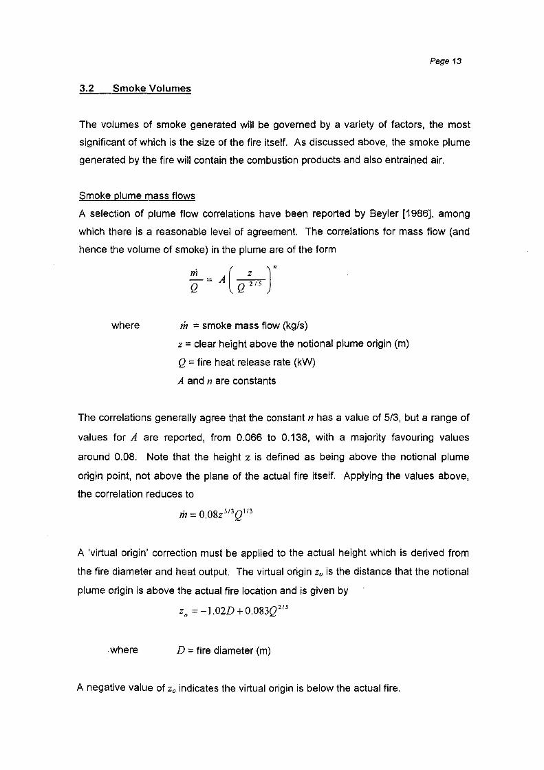
A selection of plume flow correlations have been reported by Seyler [1986), among
which there is a reasonable level of agreement. The correlations for mass flow (and
hence the volume of smoke) in the plume are of the form
where m =smoke mass flow (kg/s)
z = clear height above the notional plume origin (m)
Q = fire heat release rate (kW)
A and n are constants
The correlations generally agree that the constant n has a value of 5/3, but a range of
values for A are reported, from 0.066 to 0.138, with a majority favouring values
around 0.08. Note that the height z is defined as being above the notional plume
origin point, not above the plane of the actual fire itself. Applying the values above,
the correlation reduces to
m = 0.08z 513Q113
A 'virtual origin' correction must be applied to the actual height which is derived from
the fire diameter and heat output. The virtual origin zo is the distance that the notional
plume origin is above the actual fire location and is given by
zo = -1.02D + 0.083Q 215
where D = fire diameter (m)
A negative value of zo indicates the virtual origin is below the actual fire.

Page 14
Buchanan [1994] also discussed a mass flow correlation from Hinkley, which (when
typical ambient values are applied) reduces to
m = o.I88pY 3'
2
where p = fire perimeter (m)
Y = clear height above the fire (m)
Heskestad [1995] gives correlations for mass flow for the region below the mean
flame height, as well as above the flaming region. The equations are:
(above the flame region)
(in flame region)
where
m = 0.0056Qc ~
Qc = the fire convective heat release rate (kW, typically 70% of
the total heat release rate)
L = flame height (m)
= -l.02D+0.235Q215
Hesestad's correlations appear to be similar to the ones used to calculate smoke
plume volumes in the FPETool computer package, except for slight differences to the
constants.
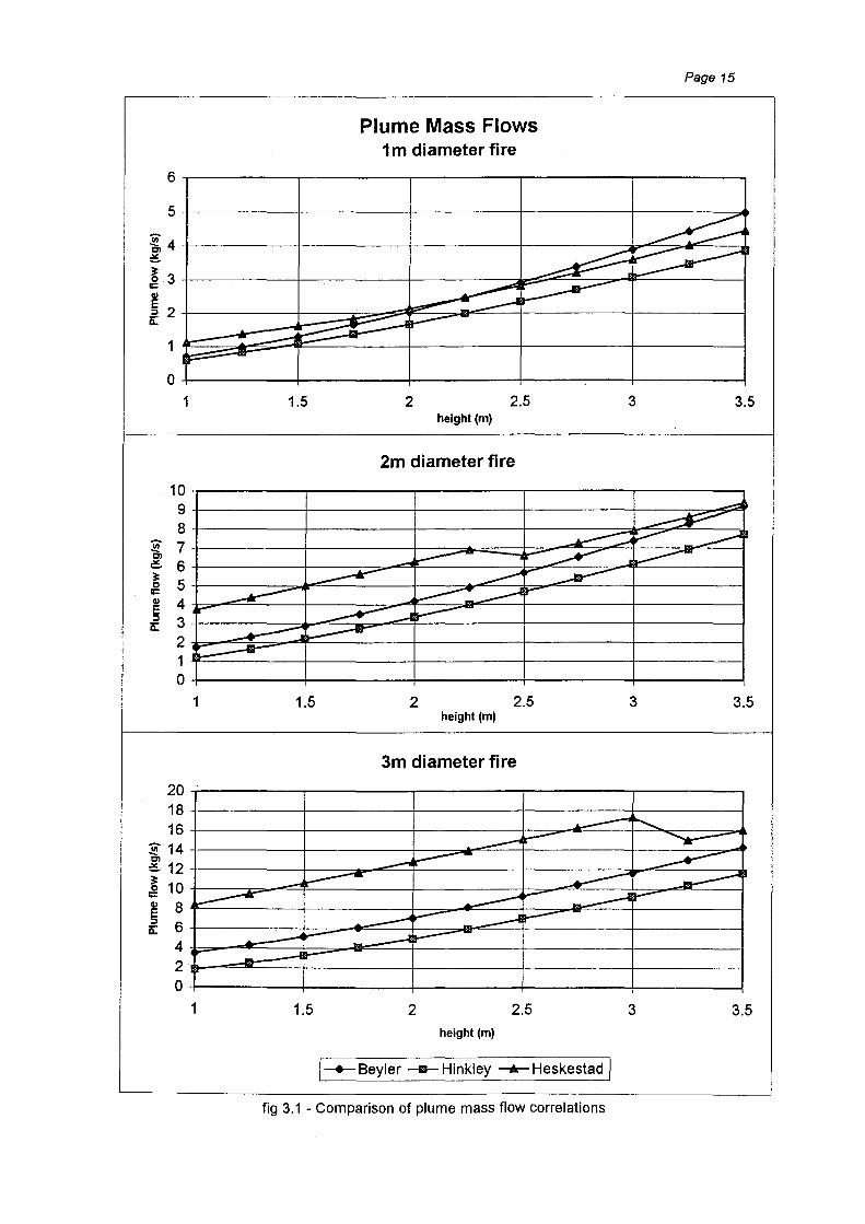
The three equations given above for the mass flow rates give similar results in the
range of values under study here (fire diameters 1 to 3m, ceiling heights around 2.5 to
3m), as shown in figure 3.1.
Smoke plume temperatures
These mass flow rates can be converted to volume flows if the smoke temperature is
known. As the smoke is mainly air, which has a density of 1.21 kg/m3 at 17°C (290K),
a simple ideal gas law assumption can be used to estimate the smoke density from
Plume Mass Flows 1m diameter fire
Page 15
~4 +----------+----------+----------+----------~~~~--_. ~
~ 3+----------+--~------+---------~~~~~~~--------~ II:
~ 2 ~ t----------t-=~~~~~~~~~-t----------t----------~
0+----------+----------+----------+----~----+---------~
-.!!! Ol ~
~ II: ~
E :I
0:::
1
10 9 8 7 6 5 4 3 2 1 0
20 18 16
:F 14 Ol ~ 12 ~ 10 = ~ 8 f 6
4 2 0
1.5 2 2.5 3 3.5 height (m)
2m diameter fire
~ ~ ---......
~ ~ ~ ..... ...-- , :.........- .J....---____.- _.-A ~ _..--
__.--- ~____... lr ..-
~~ ~ _..---::::; ;:_--a-~
1 1.5 2 2.5 3 3.5 height (m)
3m diameter fire
~- ............. ___....... ..---- ............ -
__....... ~ __.--__. .------ _...---- ~
~ ~ lo-"' ___-I ~
...... ~ ~ _.-1 ~
....-~ ....---~
.-1 ~~
~ _._
1 1.5 2 2.5 3 3.5 height (m)
1-+--Seyler --11- Hinkley ---+- Heskestad /
fig 3.1 - Comparison of plume mass flow correlations

Page 16
= 1.21( 290 J Ps Ts+273
where Ts = smoke plume temperature (0 C}
The average temperature of the smoke plume at any height can be estimated by
assuming that all the heat convected away from the fire is contained within the plume,
and that the plume is well mixed. From a simple heat balance, the convected heat
must equal the energy in the plume fluid, ie
where
Qc =me p(Ts- To)
cp = specific heat of plume (kJ/kgK, assumed to be same as air)
To = ambient temperature (0C}
Which can be rearranged to become
So using the equations above, the smoke volume can be calculated at a particular
height above the fire for any given fire heat output.
However, for all of these calculations, an estimate must be made of the design fire
size.
Design fire sizes
The fire load is not usually well defined in that the combustibles are not generally
confined to specific areas but are dispersed throughout the building. This makes the
estimation of an expected fire size difficult to determine with any degree of precision.
However, in buildings fitted with sprinklers where the fire growth rate can be estimated
(from knowledge of the typical fixtures and fittings in the occupied spaces), a
calculation can be made of the fire size which will activate a sprinkler head and an
assumption made that the fire will not grow any larger once the sprinkler is activated.
Page 17
As an example, in a room with a 2.7m ceiling and a 3 by 4m grid of sprinklers with a
response time index of 250 (ms)112, the sprinklers will activate when a fast growing fire
reaches about 1700kW, or about 2.1m diameter (based on a typical energy density of
0.5MW/m2), at which time it will be producing about 8 to 10m3/s of smoke (8,000 to
10,0001/s) at temperatures of around 200 to 270°C immediately above the fire. For
this design fire, the smoke control system must be designed to cope with
temperatures and volumes of this magnitude. This calculation can be carried out by
hand, but the more frequent approach is to use one of the commonly available
computer programs such as FPETool and Fastlite to carry out these calculations.
As a comparison for this design fire size, the Acceptable Solution C3/AS1 includes
design fires to be used for calculation of smoke volumes in certain sprinklered
buildings containing 'intermediate floors·· where mechanical smoke control is required.
Depending on the occupancy type the design fire could be either 1.5MW with a 7m
perimeter (ie. 2.2m diameter and 0.38MW/m2), or 5MW with a 12m perimeter (3.8m
diameter, 0.44 MW/m2). Note that these values are suggested for larger spaces, such
as atria, and not multistorey buildings. They are included here for comparison
purposes.
An alternative for hand calculation, using the equations above, is to assume that the
fire size will not grow past the point where it is controlled by the sprinklers, and
therefore it's size will not exceed the sprinkler spacing (say 4.6x4.6m, for a 'extra light
hazard··· occupancy). The smoke volume calculated in this scenario is over 30m3/s.
For unsprinklered buildings, the fire will not be controlled and will continue to grow, as
will the volume of smoke produced. Any smoke control system will probably be
overwhelmed quickly unless it is specifically designed for very high volumes and
elevated temperatures. It is therefore important to consider the smoke control system
as part of an overall fire safety strategy, not just as an isolated system.
• An 'intermediate floor' is defined in the Annex to the Building Code Approved Documents as an upper floor within a firecell which Is not smoke-separated from the floor(s) below. In this context it usually covers an atrium within a building. •• Such as an office, as defined by NZS4541 :1996 "Automatic Fire Sprinkler Systems"

Page 18
3.3 Leakage Paths
Knowledge of the air leakage paths that exist in any building is vital to the proper
design of smoke management systems.
To a casual observer, modern buildings appear to be relatively air-tight and to some
degree they are. However, glazing systems contain drainage tracks, wall construction
includes building tolerances, exterior doors require operating clearances and all
component assemblies contain allowances for differential thermal expansion of the
various constituent parts. These otherwise insignificant gaps all allow air to pass
through and can add up to substantial areas over the total building surface area.
Within the building, the possible paths for air flow are much more numerous. Lift
shafts, stairways and service risers all provide direct vertical flow paths, each having
one or more doorways (complete with clearance cracks) allowing access at each level.
Buildings also usually have HVAC ducts running horizontally on each floor as well as
vertically between floors. Floors are penetrated to allow electrical cables or plumbing
to pass through.
All these gaps and cracks provide leakage paths, allowing air to pass through the
building envelope or between spaces within the building. The direction of air flow will
depend on the relative pressures either side of the path. The magnitude of the flow
depends on both the size of the leakage path and the magnitude of the pressure
differential.
The availability of air flow paths, both through the building exterior and within the
building, will allow air to move around the building under the influences of the HVAC
system, stack effect or wind. Similarly, smoke can move from area to area under
these influences or due to the natural buoyancy of the hot gases. Conversely, smoke
can be kept out by selectively forcing air into adjacent zones and utilising the leakage
paths to pressurise the zones.
Little research appears to have been carried out on the amount of leakage area that is
found in a typical construction. Klote [1995) quotes values for leakage areas that

Page 19
were measured in a relatively small number of tests carried out by the National
Research Council of Canada in the 1960s and 70s, and notes that leakage areas are
primarily dependent on workmanship rather than construction type.
construction cracks, cracks around
windows and doors)
Stairwell walls (includes
construction cracks but not cracks
around windows or doors)
Lift shaft walls (includes
construction cracks but not cracks
around doors)
Floors (includes construction
cracks and areas around
penetrations)
Average
Loose
Very Loose
Tight
Average
Loose
Tight
Average
Loose
Tight
Average
Loose
= wall area, AF = floor area
Evaluated at 75Pa for walls and 25Pa for floors
0.21 X 10"3
0.42 X 10"3
0.13 X 10"2
0.14x1
0.11 X 10·3
0.35 X 10'3
0.18 X 1
0.84 X 10"3
0.18 X 10"2
A/AF
0.66 X 10"5
0.52x10⁻⁴
0.17x10"3
Figure 3.2- typical leakage areas for walls and floors of commercial buildings•
ASHRAE [1989] also gives data on leakage areas through particular building
components.
Brundrett [1997] outlines a testing program in progress in the UK which is measuring
leakage rates in a range of buildings with a view to ultimately minimising energy
wastage due to infiltration. The tests are establishing leakage in terms of cubic
metres per hour, per square metre of fayade area at a particular pressure difference.
This data could be related back to leakage areas (averaged over the whole building)
• Data from Klote [1995]
Page 20
but does not isolate particular components. Values reported to date are 5 to 27
m3/h/m2 at SOP a, which equates to leakage areas of 0.24x1 o·3 to 0.13x1 o·2 m2/m2,
falling into the 'average' to 'very loose' categories in the table above.
There does not appear to be any equivalent data available on New Zealand
construction techniques.
3.4 Fires in Air Conditioning Equipment
Statistics on New Zealand fire events are kept by the NZ Fire Service for all incidents
that they attend. Their publication "Emergency Incident Statistics 1993-1997" [NZFS,
1998], which covers data from their July-June reporting years, lists 48 incidents where
air conditioning units were described as the source of ignition and a further 21 where
the ignition source was a hot air duct or heat transfer system, out of a total of 17,292
structure fire incidents*. These combined represent only 0.4% of the total structure
fires attended.
Data was obtained directly from the Fire Service on these incidents and also on others
which occurred over a longer period (1991 to mid-1998). This enabled some
additional analysis to be carried out, including the isolation of 14 incidents where the
source of the fire was the air conditioning equipment and some smoke or flame travel
had occurred via the air ducts.
Of particular note about these 14 incidents were the following statistics:
1. In no incident did the damage extend beyond the equipment that was the fire
source. In 6 of these incidents the damage was described as nil.
2. In 4 incidents the fire had self-extinguished and in a further 6 the fire was
extinguished by isolating the power to the equipment.
• The statistics are drawn from the 241,042 incidents of all types to which the Fire Service turned out over the period, including false alarms, vehicle accidents, structure fires and non-structure fires (eg vegitation).
Page 21
3. In 3 incidents the fire was described as having past the smouldering stage into a
flaming fire. In one of these the fire had self-extinguished before the Fire Service
arrived.
4. The causes of the fires were evenly divided between electrical short circuits,
mechanical (friction) and other miscellaneous faults.
The conclusion reached from all this data is that fires due to air conditioning
equipment failure are very unlikely, and those that do occur are of a relatively minor
nature.
Page 22
4. TYPES OF HVAC SYSTEMS
HVAC systems are intended to move high volumes of air from one part of a building to
another and can therefore also move large quantities of smoke, either intentionally (to
prevent it causing a hazard to the building occupants) or unintentionally (thereby
creating a hazard). The flows and pressures generated by the HVAC equipment can
be utilised to enhance the safety of the building by either removing smoke from the
fire zone or by preventing smoke from entering the spaces where people are present.
Using the HVAC system has a major advantage over dedicated smoke management
equipment in that it is operated every day and any malfunction will be noticed and
rectified quickly. Plant that is tested relatively infrequently (and often in isolation and
only for short periods) could have faults go unnoticed or unremedied for a
considerable time. The danger with using the air conditioning equipment is that any
maintenance or modifications that are carried out must fully recognise the dual role
and not inadvertently bypass or defeat the emergency features.
For the purposes of this report, air conditioning and ventilation systems can be divided
into two basic categories in relation to the amount of fresh (outside) air delivered to
the occupied space.
(1) those that provide only the minimum fresh air to the space with the
remainder being recirculated within the space, and
(2) those that provide for all the air delivered to come from outside the
space.
The former category includes such systems as fan coil units, induction units, hydronic·
units and split systems. They are all characterised by their recirculation of a high
proportion of the air that they deliver, taking it from the occupied space and passing it
through a local heating and/or cooling unit and returning it to the space, with only a
minimum of fresh air added to maintain habitable conditions for the occupants.
Normally, each unit serves only a single space or a small group of spaces. These
systems are typical of those found in a wide range of office accommodation,
• Sometimes known as water source heat pump (WSHP) systems
Page 23
particularly in smaller buildings. The fresh air delivery is often from a separate air
handling unit (perhaps just a simple fan) located remote from the occupied space and
serving many or all of the units in the building. The important feature which
distinguishes these systems from the second category is the minimal amount of air
which is introduced from outside the space, and this volume is not usually able to be
varied during normal operation.
The second category includes systems with larger air handling units which deliver all
the air to the space. Systems such as variable air volume (VAV), constant volume
and dual duct systems are included, which comprise large air handlers remote from
the occupied spaces and a ductwork reticulation system of risers, main and runout
ducts (the 'supply air' system) to distribute the air to many spaces simultaneously.
The air delivered to the space is later returned to the air handler via another network
of ducts (the 'return air' system). Frequently these systems are capable of delivering
a mixture of fresh and recirculated air, or all fresh air to the occupied spaces.
It is not unusual for a building to contain more than one type of system, with different
systems serving different parts of the building. There may be (for example) a VAV
system serving the inner zones of the typical office floors, with induction units around
the perimeter of the floors and fan coil units in a ground floor retail area.
Both categories are discussed in more detail below under the headings of Unitary and
Central Plant systems, respectively.
The systems covered are the main categories of HVAC equipment found in New
Zealand multistorey buildings. The descriptions that follow concentrate on the air
handling abilities and features of the various systems, as these are the most relevant
to the capabilities for smoke control. Other features are noted in general terms only,
for the information of the reader.
It is worth noting that typically both categories of system operate with an excess of air
supplied into the occupied space over that which is extracted. The balance migrates
out of the building via minor extract systems including toilet and kitchen exhausts and
also by a variety of leakage paths such as cracks around doors and windows,

Page 24
construction cracks and so on. This excess of supply is done deliberately to slightly
pressurise the building with respect to the outside, to prevent the infiltration of
unconditioned outside air.
4.1 Air delivery rates
The 'energy crisis' of the early 1970's forced air conditioning designers to consider
methods to reduce the energy requirements of HVAC systems. One means was to
retain the maximum conditioned air possible within the space by recirculating as much
air as possible and reducing the amount of fresh air introduced. Fresh air rates were
typically decreased to 51/s per person, or 0.51/s per square metre (floor area) or less,
depending on the occupancy rate (persons per square metre)
Since then, minimum fresh air rates have been increased due to concerns such as
'sick buildings' so that they are now typically a minimum of 1 01/s per person, or around
11/s/m2 for typical office accommodation.
The quantity of conditioned air that is supplied to a space is matched to the heating or
cooling load of the equipment and people that occupy it. The air quantity that is
required for this duty is normally significantly greater than the fresh air rate alone. In a
normal office occupancy, air volumes of 6 to 101/s/m2 would be needed to match the
heating/cooling load, ie 6 to 10 times more than the fresh air volume alone.
Depending on the type of HVAC system, the difference could be made up from air
recirculated within the space, air recirculated and diluted by a remote air handler or
new air introduced from outside.
In temperate climates such as New Zealand's, one energy saving method does have
a positive side effect which is useful to the fire engineer. Buildings usually have a
large (in relation to the total floor plate area) central zone which contains people and
equipment, all producing heat, with nowhere for this heat to be dissipated. This
means that even during winter conditions the principal HVAC objective is to provide
cooling. A method often utilised in central plant installations is to introduce high
proportions of cold outside air as 'free cooling', with the used air being expelled from
Page 25
the building via the return air system. Supply of 100% fresh air is often used. The
consequence in many buildings is that fans and air flow control systems are already in
place which are ideally suited to the purposes of smoke control as they can move
large quantities of air (or smoke) from any potential fire site.
As noted in section 3, smoke volumes produced in a sprinklered building will easily be
of the order of 8000 to 10,0001/s. It follows that an air conditioning plant designed to
ventilate occupied areas of at least 800 to 1 000m2 at a rate of 1 Ol/s/m2 may be
capable of handling the volumes of smoke that could be produced. Smaller plant will
likely be overwhelmed by the volumes of smoke to be handled.
4.2 Unitary Systems
4.2.1 Description of Unitary Systems
Unitary systems comprise a number of small air handlers, each located close to the
area being conditioned - typically in the ceiling space above. These air handlers are
fed fresh air by an external system, either passively or via a fan system, and are also
supplied with their heating and/or cooling medium from outside the space. They are
usually only capable of recycling the air from within the occupied space with a
minimum make-up of fresh air, the balance being reconditioned within the unit before
being returned to the space.
They normally contain a single fan which both supplies the air to the occupied zone
and also provides the suction to return the recycled air back to the unit. The quantity
of air which is not recycled is usually allowed to find its own path out of the building,
via leakage around windows and doors as well as via miscellaneous extract. systems
such as toilet or kitchen extracts. All unitary systems operate on similar principals,
with only the heating/cooling medium changing.
Most (but not all) unitary systems have electrically driven equipment contained within
the unit. These can be a source of ignition if electrical faults occur.
Page 26
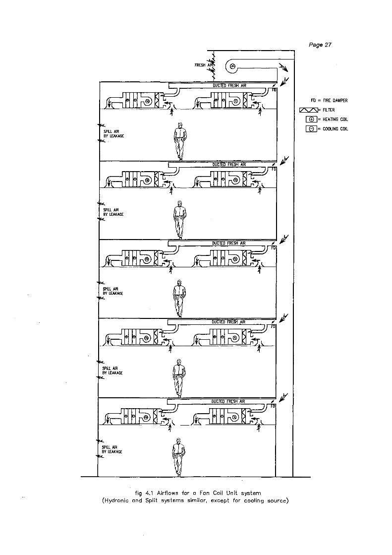
Fan Coil Units (FCUs)
Fan coil units (fig 4.1) are probably the most common form of unitary HVAC
equipment found in multistorey buildings, most frequently in smaller buildings and
hotels but sometimes also found in lesser quality high-rises. They consist of a simple
electrically driven fan and a heat exchanger coil, similar to a car radiator. Air is forced
over the coil by the fan, while hot or cold water is circulated through the coil to heat or
cool the air. Usually some form of air filtration is included.
Induction Units
These are similar to fan coil units but are of even simpler construction (fig 4.2).
Instead of a fan inside the unit to circulate the air, these units are provided with a
relatively high pressure air supply from a remote air handler which is ejected from
nozzles within the unit. This high velocity air induces a circulation of external air
through the unit which is passed over a coil in the process. These systems are now
relatively uncommon in new buildings as they have a (somewhat undeserved)
reputation of being noisy and expensive to operate.
It is worth noting that induction units have no electrically driven components within the
unit. All the powered equipment is located in the remote air handler.
Hydronic (WSHP) Units
Hydronic units are also sometimes known as Water Source Heat Pump (WSHP)
units. They are similar to fan coil units except in the manner in which they produce
the heating or cooling for the air. These units contain their own refrigeration
equipment which operate to provide cooling or heating directly into the coil. They
require only an external source of electricity and cooling water to operate.
®r-----,~
.-------;==~==~~~===~; Jl
fig 4.1 Airflows for a Fan Coil Unit system (Hydronic and Split systems similar, except for cooling source)
Page 27
FD = FlRE DA~PER
~FILTER
[][)= HEATING COIL
I 0 I= COOUNG COIL

fig 4.2 - airflows for Induction Unit systems
Page 28
FD = FlRE DAt.IPER
IZSZSF FlL TER
[][)= HEAliNG COIL
(];2]= COOIJNG COIL
Page 29
Split Systems
Split systems comprise two separate components for each unit - an indoor air
handling unit and an outdoor condensing unit, connected by a circuit of pipework
containing refrigerant. The indoor unit is essentially a fan coil unit with refrigerant
rather than water flowing through the coil. The outdoor unit contains the refrigeration
equipment that is required to produce the cooling effect. Indoor units can be mounted
in concealed spaces such as ceiling voids, or can be wall or floor mounted within the
space. The units only require an external electrical supply to operate.
Through-wall or window units have the indoor and outdoor sections close~y coupled
into a single cabinet and usually have a fresh air supply feature built in to the unit.
An extension of the split system is the multi-unit system where several indoor units are
connected to a single outdoor unit, often incorporating some control on the amount of
refrigerant flowing around the system and hence called variable refrigerant volume
systems (VRV).
4.2.2 Suitability of Unitary Systems for Smoke Control
Because unitary systems are designed to recirculate most of the air that they handle,
their ability to either remove smoke or provide pressurisation is very limited. As noted
previously, they have only a small amount of fresh air provided and usually do not
have any separate 'used air' removal facility included.
Smoke removal
Unitary systems therefore cannot be used to remove smoke from an affected area
without an additional air/smoke removal fan and duct being provided. These require
space which reduces the lettable area in the building. The drive to gain maximum
usable floor area puts pressure on architects and designers to eliminate unnecessary
riser space and to use alternative means of achieving fire safety, such as stair
pressurisation.
Page 30
The author is not aware of any building in New Zealand that has unitary air
conditioning with a separate, dedicated smoke extract facility included as part of the
design.
Pressurisation
The relatively small volumes of outside air introduced to the occupied spaces means
that the ability of the system to provide a significant pressure differential is minimal.
As discussed in section 5 of this report, what ability the fresh air system does have to
provide pressurising may be contrary to the smoke management objectives in the
building. The introduction of outside air during a fire condition may in fact force the
smoke into the stairs and riser shafts and aid its spread to other parts of the building.
Smoke Production
By design, the unitary air conditioners draw air from the occupied space, treat it and
then reintroduce it to the space with as much mixing as can reasonably be achieved
without causing discomfort to the occupants. The air is usually delivered at ceiling
level via air diffusers. As this is also the level at which any smoke will accumulate it is
apparent that the mixing will also mix air and smoke, if it is present, thereby creating
more smoke. This obviously has the potential to aggravate a fire situation.
Summary
The conclusion traditionally drawn from the factors above is that the safest course of
action is to stop unitary systems and their associated fresh air systems on the
activation of a fire alarm.

Page 31
4.3 Central Plant Systems
4.3.1 Description of Central Plant Systems
Central plant air conditioning systems consist of large air handlers that provide
conditione,d air to the occupied spaces via a distribution system of ductwork, including
risers, main and run-out ducts. They are characterised by supplying all or most of the
air from the central air handlers, and then returning it all back to the air handler for
recycling or spilling to outside. These air handlers may be located in plant rooms on
only one or two floors of the building, or may by constructed every floor (known as
floor-by-floor air conditioning).
It is usual for these systems to have separate supply air handlers and return fans, with
the return systems sized to return about 80% of the supply air quantity back to the
central plant for either recycling or spilling (or some of both).
In central plant systems the electrically driven equipment is usually located in the main
air handlers.
Variable Air Volume (V AV)
VAV systems (fig 4.3) supply only the airflow to a particular space that is required to
match the heating or cooling needs of the space or zone at the particular time. They
have to be capable of supplying a high volume of air at times of peak loading so the
air handlers are typically large capacity units, able to supply many spaces
simultaneously. Each zone has some form of terminal unit to vary the local air flow to
match the demand.
VA V system controls are often relatively complex, as they must adjust the volume of
air delivered by the air handler in response to multiple demands from the various
spaces.

SUPPLY RATE VARIES
SUPPLY RATE VARIES
SUPPLY RATE VARIES
SUPPLY RATE VARIES
Page 32
~D = L!DTDRISED DA~PER
FD = flRE DAMPER
IZSZSI= flL TER
[]t[}= HEA TINC COIL
CEJ= COOUNG COIL
fig 4.3 - airflows for a Variable Air Volume system

Page 33
Depending on the control system fitted, the terminal units may be able to supply or
shut off air to particular spaces on receipt of a fire signal. This feature has the
capability to be used to provide zone control of smoke, but the designer and the
maintenance staff must be aware of the importance of all parts of the system
operating as intended, if it is to be used reliably as part of the building's safety system.
A variant on the standard VA V system is to use some fan assistance in the terminal
units to aid the circulation of air during times of low air conditioning demand, to avoid
stagnation or stratification of the air within the space.
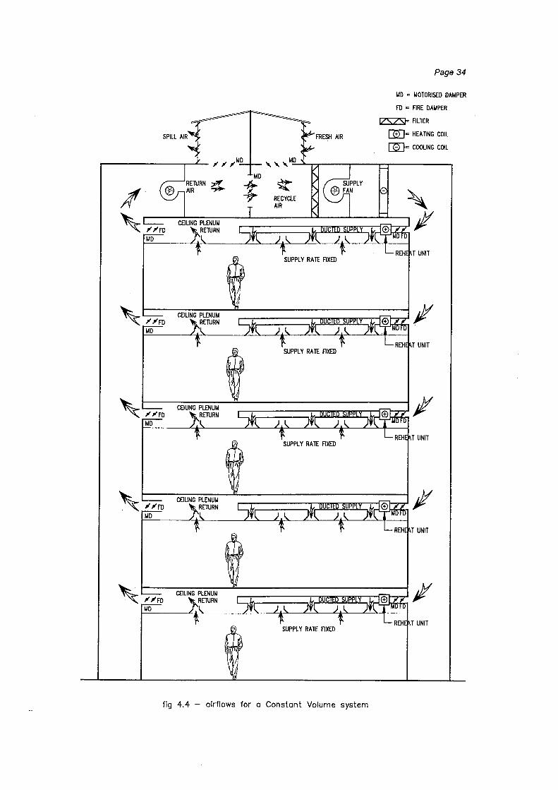
Constant Volume (CV)
(Fig 4.4) These systems are not commonly installed nowadays due to their relatively
inefficient use of energy. As the name suggests, they provide a constant amount of
conditioned air to the space which is then usually given some additional heating or
cooling to match the requirements of the space. The consequence is that the air from
the central air handler is usually over-conditioned to cater for the highest demand and
then re-conditioned locally for the other spaces - a wasteful exercise. On the plus
side, these systems are simple and reliable, and can often be adapted to provide
some zone control by the addition of relatively few control dampers (where these are
not already fitted).
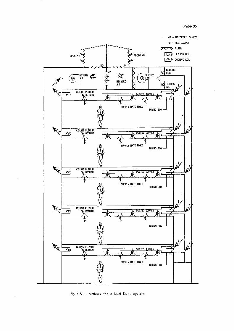
Dual Duct
Similar to constant volume systems, these deliver a constant amount of air to the
occupied spaces, but it is through two independent duct systems (fig 4.5). After the
air handler, the air path splits into two and the air is heated in one and cooled in the
other. At the occupied space the two ducts again meet at a mixing box where the hot
and cold air is combined in the appropriate ratio to match the space's requirements at
the time. Dual duct systems are not common in new buildings.
SUPPLY RATE FIXED
SUPPLY RATE FlXED
SUPPLY RATE FlXED
SUPPLY RATE FIXED
fig 4.4 - airflows for a Constant Volume system
Page 34
MD ~ I.IOTDRISED DAMPER
FD ~ FIRE DAMPER
IZSZSt= FILTER
[]LIE HEAliNG COIL
m:J= COOLING COIL
T UNIT
FRESH AIR
fig 4.5 - airflows for a Dual Duct system
Page 35
1.40 ~ t.40TDRISED DAt.4PER
FD = FIRE DAUPER
IZSZS}= FlLlER
[]L)c HEAllNG COIL
[ID= COOUNG COIL
Page 36
4.3.2 Suitability of Central Plant Systems for Smoke Control
Central plant systems are designed to return all or most of the air that they handle
back to the air handlers in remote plant rooms. Therefore, they are usually well suited
to either remove smoke or provide pressurisation by selective airflows. They
frequently have the ability to draw in all fresh air and to spill large quantities of
exhausted air and smoke products. The ability to pressurise zones within the building
has the potential to significantly enhance the safety of the occupants.
Smoke removal and pressurisation
The return air fans are usually of sufficient capacity to exhaust quantities of smoke
comparable to those produced by a sprinkler controlled fire and can be specified to be
suitable to operate at the expected smoke temperatures. Control systems are
frequently already in place or can be modified to achieve selected air supply and
exhaust to achieve zone pressurisation. Care must be exercised, however, to ensure
that if the control systems and devices fail they will do so into a safe condition if they
are to be relied upon as a safety system.
Smoke Production
Similar to the unitary systems, central plant systems also usually supply air at ceiling
level which will be above any smoke layer produced by a fire. This obviously has the
potential to aggravate the situation by causing mixing which creates more smoke.
Summary
On balance, in the author's opinion the advantages of having an active smoke control
system outweigh the disadvantage of possibly increasing the smoke volume being
produced and any central plant system that can be operated in a smoke control mode
should be given serious consideration as an active smoke management system.
Page 37
4.4 Other Systems
Displacement Systems
Displacement systems utilise large volumes of air introduced at very low velocity at
floor level in the occupied space, allowing the air to move by natural convection as it
heats up, to finally be extracted at ceiling level. The air handling units could be of
either unitary or central plant type. The very low velocities used equate to low
pressures within the equipment and it is unlikely that the air handlers can be used to
control smoke movement. Also, as the air is supplied at floor level, particular care
would be required to ensure that smoke is not inadvertently drawn in with the supply
air and delivered directly into the space where people are present.
Floor by Floor units
Floor by floor units are the half'-way stage between unitary and central plant systems.
In multi-storey buildings the designer sometimes prefers to have a small amount of
equipment in a plantroom on each floor rather than concentrating all the equipment
into a large plantroom occupying a whole floor, or conversely having the units located
in the ceiling of the occupied space. These systems can have all the characteristics
of central plant systems but on a smaller scale. They can usually operate in full fresh
air mode in the same way, and can therefore be considered for smoke control
purposes.
Page 38
5. COMPUTER MODELLING
To enable. some conclusions to be drawn on the relative abilities and risks of HVAC
systems under fire conditions, several 'typical' buildings were modelled (using
CONTAM96 [Walton 1993]) to determine likely airflow directions and pressures for a
variety of situations under the influence of stack effect and it's interaction with
mechanical systems.
Under conditions of normal stack effect (internal temperature higher than external),
the density difference between the warm air inside the building and the cool air
outside causes the air flow in the building to be generally upwards, utilising flow paths
such as lift shafts, service risers and stairways. Air will flow into the building at low
levels and out at higher levels. At approximately the building mid-height there is a
point where the flow is neither in nor out which is known as the neutral plane.
Therefore the worst case under these conditions is a fire on the lowest floor, as the
smoke will be transported into and within the building rather than being expelled to the
outside.
5.1 Buildings Modelled
The buildings modelled are defined below. They are intended to represent typical
multistorey office buildings in New Zealand and are derived from the author's
observations of many buildings throughout the country.
1. A three storey building with a single lift.
2. A seven storey building with two lifts in a common shaft.
3. A ten storey building with three lifts in a common shaft.
4. A twenty storey building with two lift banks - a low rise group of four lifts with a
machine room at the 131h level and a high rise group of four lifts with a roof
machine room. Low rise lifts have entrances on all levels 1 to 11 and high rise lift
have entrances on levels 1 and 11 to 20.

Page 39
Features which were kept common to all of the buildings were:
• Floor plate size - each floor was kept at 800m2 with a perimeter of 120m (ie a 30m
square building with a 100m2 core).
• Floor to floor height of 3.5m, giving building heights (ground to highest occupied
floor level) of 7, 21, 31.5 and 66.5m.
• Stairwell - each building had a stair core of 16m2 and a perimeter of 16m, with the
ground level stair doors opening to outside.
• Lift core - each lift shaft was taken as occupying a 3x3m space (ie a three lift
group took up 27m2 and had a perimeter of 24m).
• Roof - at the roof level of each building was a lift machine room (LMR) ahd the top
of the stairwell. The LMR floor area was four times the size of the lift shaft below.
Each lift had a 0.09m2 rope penetration to the shaft below and the LMR was linked
to the stairwell by a single door. The stairwell also had a single door directly to the
outside.
• On the ground floor, two doors went to the outside and also the stairwell was
linked to the outside by two doors.
• The building fabric was taken as being of 'average' construction tightness as
defined by Klote [1995], except for roof LMR construction which was taken as
being 'loose'.
• Stair doors were taken as having a 3mm crack all round, with lift doors and ground
floor entry doors having a 6mm gap all round.
• Interior temperatures were set at 21 oc (as is normal for office environments) with
external temperatures of -4oc•.
The building internal layout was assumed to be simple with the lifts and stairs opening
directly onto the occupied space. No attempt was made to model any internal fitouts
or lobbies that may be installed, as these would only restrict smoke movement. The
open plan layout is therefore the worst case with the most free smoke migration.
• This temperature is the 1% winter design temperature for Dunedin, being the coldest winter design temperature for the main centres, as published by the National Institute for Water and Atmospheric Research (source: IHRACE Journal, July 1996).
Page 40
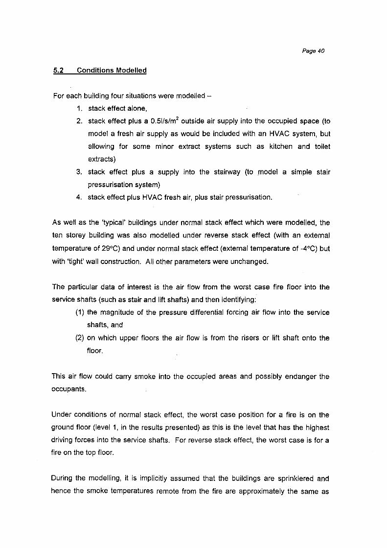
5.2 Conditions Modelled
For each building four situations were modelled -
1. stack effect alone,
2. stack effect plus a 0.51/s/m2 outside air supply into the occupied space (to
model a fresh air supply as would be included with an HVAC system, but
allowing for some minor extract systems such as kitchen and toilet
extracts)
3. stack effect plus a supply into the stairway (to .model a simple stair
pressurisation system)
4. stack effect plus HVAC fresh air, plus stair pressurisation.
As well as the 'typical' buildings under normal stack effect which were modelled, the
ten storey building was also modelled under reverse stack effect (with an external
temperature of 29°C) and under normal stack effect (external temperature of -4°C) but
with 'tight' wall construction. All other parameters were unchanged.
The particular data of interest is the air flow from the worst case fire floor into the
service shafts (such as stair and lift shafts) and then identifying:
(1) the magnitude of the pressure differential forcing air flow into the service
shafts, and
(2) on which upper floors the air flow is from the risers or lift shaft onto the
floor.
This air flow could carry smoke into the occupied areas and possibly endanger the
occupants.
Under conditions of normal stack effect, the worst case position for a fire is on the
ground floor (level 1, in the results presented) as this is the level that has the highest
driving forces into the service shafts. For reverse stack effect, the worst case is for a
fire on the top floor.
During the modelling, it is implicitly assumed that the buildings are sprinklered and
hence the smoke temperatures remote from the fire are approximately the same as

Page 41
the building internal temperature and the same density as air. Additional buoyancy
effects from hot smoke are therefore not modelled.
The pressure differential driving the flow into the stair also gives an indication of how
difficult the flow would be to stop. This can be used to determine whether simple
smoke seals on doors would be sufficient, or the magnitude of stair pressurisation that
would be required to keep the stairway clear of smoke.
In addition to the discussion that follows, for each situation the results of the modelling
are presented in the Appendix as graphs of air flow and pressure difference against
building height (measured from level 1, up). The sign conventions used are that
positive flows are from the shaft into the occupied space (negative values indicate
flows into the shaft) and positive pressure differences are the shaft at a higher
pressure than the space. In all cases the ground floor is level 1.
5.3 Observations
The observations made of the flows and driving pressures are:
Stack effect alone
" As expected, the air flows from slightly above building mid-height are from the
vertical shafts into the occupied spaces, with flows into the shafts below mid
height. This follows the expected effect of smoke from a fire low in the building
being carried onto the upper occupied levels.
• For the 20 storey case, the flows into/out of the low-rise lift shaft are as though the
building were only 12 storeys (the height of the shaft), with flows below shaft mid
height into the shaft and above mid-height from the lift shaft into the occupied
space. The effect of the low-rise lift machine room is significant on this and the
adjacent floors, as the shaft and the machine room above are acting as a direct
channel for airflow from the lower floors.
• Under the influence of stack effect alone the driving pressures on air flow are less
than 12Pa, even for buildings of 20 storeys at an external temperature of -4°C.
For the 3 storey building the driving pressures are less that SPa.

200
150
100
50 .......... en
::::::: ...__..
3: 0 0
LL
-50
-100
-150
-200
10 Storey, Stack only
K .. ")~ ', ·, ---~
'r,~... ·-, ~
'• --,. --:.:-··.,,, __ ~ . - •. 'Jil •... - L -........._
, •. -.•. rp •• - .... - - • ~~ -.... - r·--~-~ ..
• ' -..•. -~ r:--...... . . . . ' . . ..... ~ .... ~ -.. ~~----- ..
~ -----1-----
1 2 3 4 5 6 7 8
level
I e Stair flow A Lift flow · · o · · Stair dP -- * -·Lift dP]
9
·--~ - . t
10
10
8 -ra· U1 _..
6 I )>
5: 0 :E 4 (/) -0
.......... .... cu Ill 2 a.. _.. ...__.. 0 Q) (/) ,_ 0 ::J ..., 0 en (!)
en '< Q) t:T ,_ c: a.. 0:: -2
:J !C
:E ~
-4 $!;. Ill n 7' -6 (!) --(!)
-8 Sl Ill
0 :J
-10 (!)
\) Ill
!Q Q)
.:..
"'
Page 43
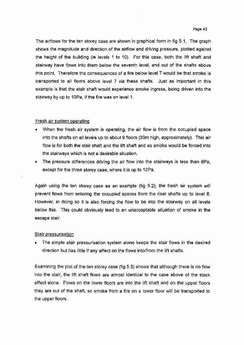
The airflows for the ten storey case are shown in graphical form in fig 5.1, The graph
shows the magnitude and direction of the airflow and driving pressure, plotted against
the height of the building (ie levels 1 to 10). For this case, both the lift shaft and
stairway have flows into them below the seventh level, and out of the shafts above
this point. Therefore the consequences of a fire below level 7 would be that smoke is
transported to all floors above level 7 via these shafts. Just as important in this
example is that the stair shaft would experience smoke ingress, being driven into the
stairway by up to 1 OPa, if the fire was on level 1.
Fresh air system operating
• When the fresh air system is operating, the air flow is from the occupied space
into the shafts on all levels up to about 9 floors (30m high, approximately). This air
flow is for both the stair shaft and the lift shaft and so smoke would be forced into
the stairways which is not a desirable situation.
• The pressure differences driving the air flow into the stairways is less than 8Pa,
except for the three storey case, where it is up to 12Pa.
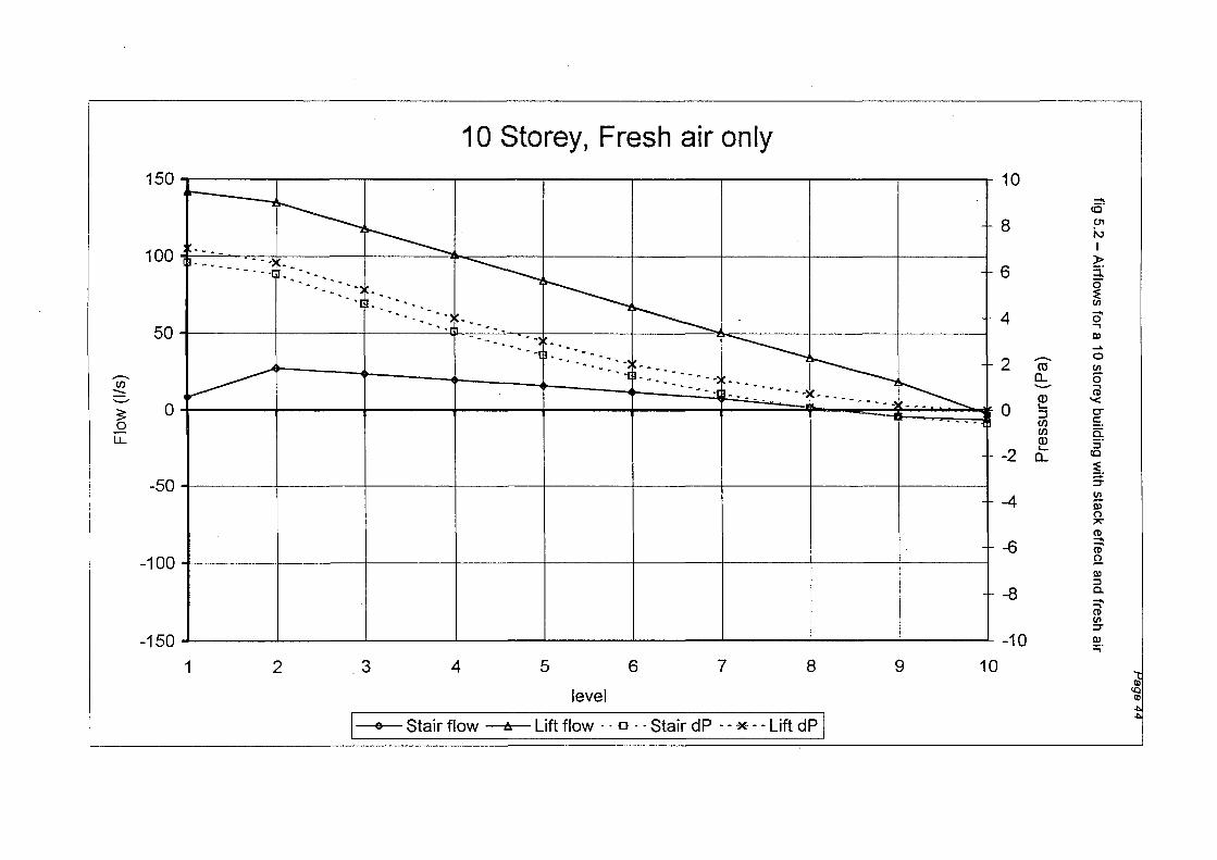
Again using the ten storey case as an example (fig 5.2), the fresh air system will
prevent flows from entering the occupied spaces from the riser shafts up to level 8.
However, in doing so it is also forcing the flow to be into the stairway on all levels
below this. This could obviously lead to an unacceptable situation of smoke in the
escape stair.
Stair pressurisation
• The simple stair pressurisation system alone keeps the stair flows in the desired
direction but has little if any affect on the flows into/from the lift shafts.
Examining the plot of the ten storey case (fig 5.3) shows that although there is no flow
into the stair, the lift shaft flows are almost identical to the case above of the stack
effect alone. Flows on the lower floors are into the lift shaft and on the upper floors
they are out of the shaft, so smoke from a fire on a lower floor will be transported to
the upper floors.
>.
c 0 s..... co ..c C
/) Q
) s.....
LL
0 ..-0 L{)
..-
J fig 5.2 -Airflo
ws for a 10 storey building w
ith stack effect and fresh air
(ed
) eJnsseJd
N
0 .
I ' I
I . ' . ' . . ' . ' '
1/ .... . . . I
. . . '
' . .
..._'..}.
I "
7 .
I
' '
I
' .. I
I
' I
' . I
I
' .
I 1/ I
. I
. .... ' _:
I f
~ :-'
I
. . . I
>
I >
.. . . . . . ' , . ..,.
' . I
'
' . . ' 0 0 ..-
' I ' . ' .
.
~ar' I
0
I '
<
I
. ' I I
.. . . . . • -'f'
'
. I
' . I
. ' . :'~ . . I
. . . I 0 L{) . . . I
. \ 0
(S/I) M
OI.:l
0 0 ..I
co I
0 ..I
0 L{)
..I
0 ..-co 0... "0
;:;:= ::J
* 1'--
0... "0
I-
·ro ...... en
(0
0
Ci5 >
3:
Q)
0 ;;:
L{)
;:;:= ::J
t 3: "¢
0 ;;: I-
·ro ...... en
('() t
N

~
c 0 c 0 +
-'
ro C
/) ·c
:::J. C
/) .C
/)
~
0.
s....
ro +
-'
(f)
>,
~
0 +
-'
C/)
0 -r-
Page 4
5
fig 5.3 -A
irflows for a 10 storey building w
ith stack effect and stair pressurisation
0 N
0 0 N
(ed)aJnssaJd
LO
0 ....-
....-LO
0
I
. I
I
' 1
. 1
7' I
. I I
. I I I
.... 1
~
l/ I
/j ~
.
v I
v ..... I
. . I
.
I j
I !
J
I 0 LO
....-
. . I
. . "' I I
. . . I
I
0 0 ....-
I
~· . I
. .
I
I
. . .
'
. I 0 LO
' . . . . ' , I
t
0
v
I 0 LO I
(S/1) MOI.:f
0 ....-1
I 0 0 ....-1
LO
....-1
0 LO
....-1
'
. !
:" . ! . . I
'
0 0 'il
0 ....-co
1"-
CD
(i) >
Q
)
LO
"¢'
('f)
N
....-
c.. "0
~
:.:J
~
c.. "0
L
..
·ro ...... U
)
0 ~ ;:;:::: ~
:.:J
t ;: 0 ;:;:::: L
..
·ro ...... U
)
t

Page 46
Fresh air plus stair pressurisation
• The combination of stair pressurising and the fresh air system is sufficient to stop
flow from the lift shaft into the occupied space up to about 10 storeys (say 35m
high).
As shown in fig 5.4, the air flow is prevented from exiting the lift shaft up to level 10.
Consequently, a combination of stairway pressurisation and leaving the HVAC
operating could be used (in the test building) to keep the occupied floors clear of
smoke.
However, to illustrate the complications that can be introduced, inspection of the flows
for a 20 storey building (fig 5.5) under the influence of stack effect only shows how
confused the flows can be, even for this relatively simple case. The high-rise lift shaft
and the stairway both have flows into the shafts below mid-height and out of the
shafts above this level (as expected). Pressures driving the flows are at maximum at
the extreme floors (1 and 20) and vary in approximately a linear fashion between.
However, the flows in the low-rise lift shaft behave as though the building were only
13 storeys tall, with a neutral plane at level 7. The consequences of a fire on level 1
would be that smoke would be transported to floors above level 7 via the low-rise lift
shaft, and to all floors above 12 via the high-rise lifts and the stairs. Adding lobbies
around lifts or subdividing floors will further complicate the flows.
Outside temperature 29°C
• The reverse stack effect is as expected, with flows above building mid-height into
the riser shafts and below mid-height into the occupied spaces (see fig 5.6).
• As for the normal stack case, the fresh air system alone is sufficient to prevent air
flows onto the occupied levels except for the extreme floor (the ground floor, in
this case) and stair pressurisation alone does not have a significant influence on
the lift shaft flows.
• The fresh air plus stair pressurisation will contain the flows in the lift shaft for all
levels except the ground.
• As expected, the driving pressures are significantly less than those calculated for
the normal stack cases. This is due to the magnitude of the temperature

10 Storey, Fresh air+ Stair pressurisation :::l co 0'1
50
--(/) :::::: ...._,
3: 0 0
LL
-50
150
~ ~ ~ -r--._ --. . . . .. "'ll
~ . . --- ••••• _"l
~
. . ~ . --- ------"'! 1---- -........
. -- ~ ....,
~ ---------~ .. -...... - ........
~ ---------~
~ -
"
10 ~ I )>
3; 0 ~ en ...... 0 ...., Ill _.. 0 en 0 ...., CD '< -- o-co !: . a. a: ...._, ::;
Cl> co '-
~ ::J (/) (/) =r Cl> !!!. '-a. Ill
0
"' CD ......
100
8
6
4
2
0
-2
...... CD g. -4 ......
-100
ro en =r Ill
-6 ...., Ill :::::1 -8 c.. !!!. Ill
-150 -10 ...., "'C
1 10 ...., CD en 2 5 9 6 7 8 3 4 en -u c :::!. Ill co en
~ ~ -t.. a· ...... :::::1
level
F--stair flow ;--Lift flo~--· a--· Stei!r dP ~-*-_.._Lift dP J
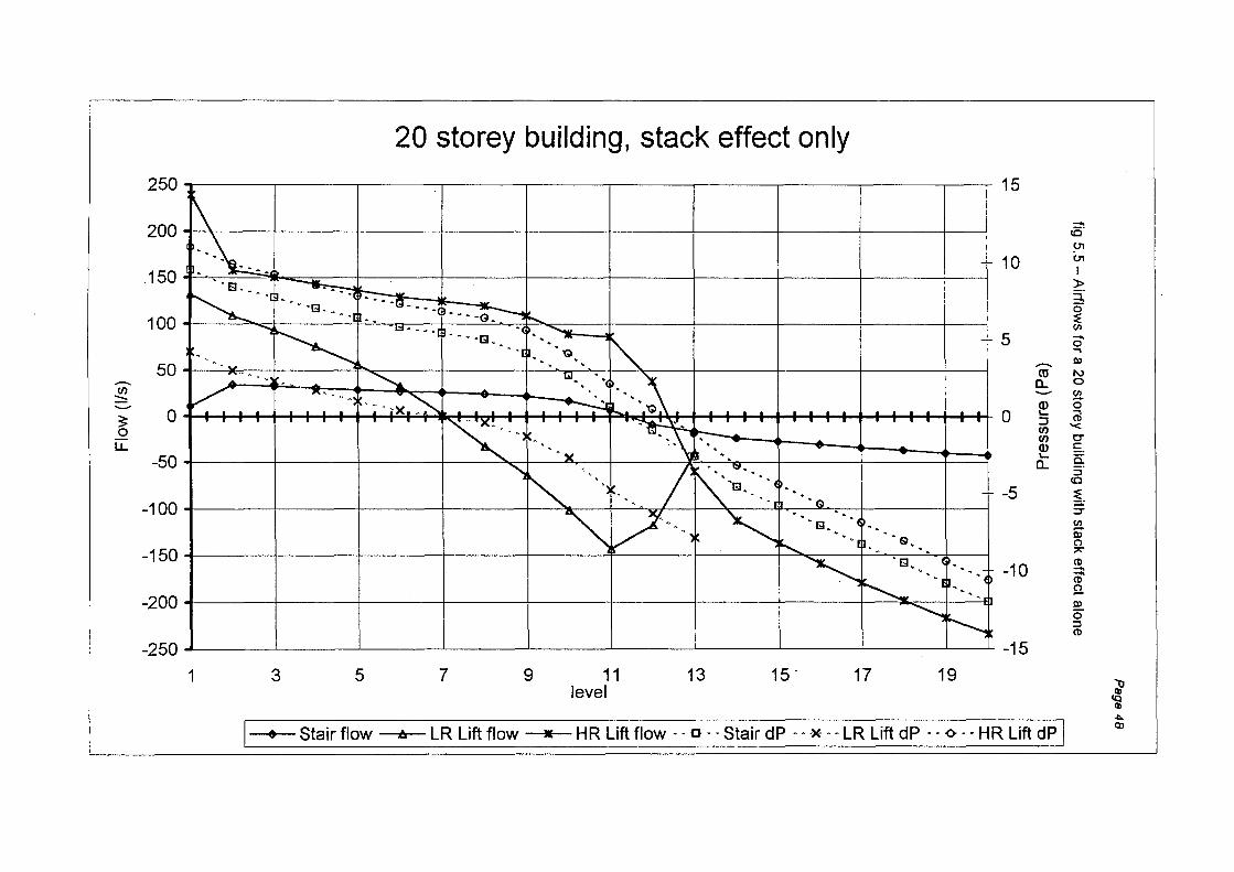
~
c 0 -0>
c 'U
::J .0
~
~
0 ~
(/)
0 N
l{)
........
0 l{)
N
fig 5.5
-A
irflows for a 20 storey building w
ith stack effe
ct alone
(ed
) aJnssaJd
0 ........
0 ........ I l{
)
0 l{
)
I
. ' j
. . .
' .
t
1-
.-
. . . . v· . m/
0 . . 0
I
,.: .
,-.:-v
·~ . . . .
~ .c
. 121 ·~
. . .
j . . . . .-ll
·~ . .
0 I
~ ~
~ pi ·~ 1 .· ·
/
·~ : .
r "" ,"
,
~
,.
\ /
<
. : 1
.;
., v
. '. '· ~
-· .
. ~: ·~
~. . :)4.
~
/ .
·~ .
. J . .
. 1-#
... ~_ <
l 7 :-
' V'
' t
v . 13 .
. . I
I
. . .:. "' '';"
':"'
v I
• I
I
~ ~ v x ,
. . . '
~ 1
' <
ll ~ ,
. '
. . ~
[lJ ·~
. ' I ·~
...: ... :
. ';"'
r ~·
' I
.
l1 .ci) '
'' ~
.' \· ./
, •'
0 0 N .
, 0 l{)
........
0 0 ........
: 0 l{) 0
(S/1) MOI.::I 0 l{
)
I
0 0 ........ I
0 l{)
........ I
0 0 ~
l{)
........ I
0 l{)
~
Pa
ge
48
a.. "0
¢::: ::i c::: :::r::
()) ¢
........
a.. "0
¢:::
f'-... ::i
........ c::: .....1
).( <
l{)
a.. ........
"0
L..
'(ij
- en (")
0 ........
~ ;:;:: ¢:::
........ ::i
........ _ Q)
c::: >
Q)
:::r::
()) f ~ ;:;:: ¢::: ::i
f'-... c::: .....1
f l{
)
~
0 ;:;:: L
.. '(ij
- en (")
t ........
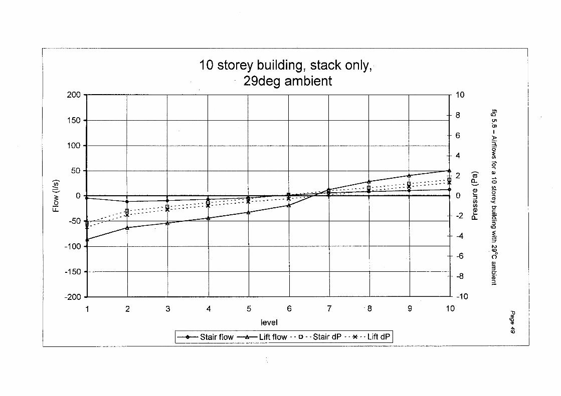
.......... (/)
:::::
~ u.
10 storey building, stack only, 29deg ambient
200~----~------~----~----~------~----~------~----~----~
150+------+------+------+------+------+------+------+------+------1
100+------+------~----~-----4------~-----+------r-----~----~
50 ·::::::::
0 ·-:::::: ::::::::: :
-50
-100+------+------+-----~------~----~------~-----+------+-----_,
-150~-----+------+------+------+------+------+------+------+------1
~00~----~------~----~----~------~----~------~----~----~
1 2 3 4 5 6 7 ·8 9 10
level
I • Stair flow A Lift flow···· o-= .. Stair_d~----=---~-~-·_Lift d~
10
::!! 8 <0
U'l m I 6 )>
3; 0
4 ~ til -. 0 ....
.......... Ql 2 ro _..
a. 0 ...__.. til
(]) 0 0 '- .... ::J (I) (/) '< (/)
0" (]) c:: -2 '-
0:: a. :J <0
-4 ~-:T 1\)
. tO 0
-6 0 Ql
3 0" -8 a;· 3..
-10
"'0 Ill (Q Q)
~ <o
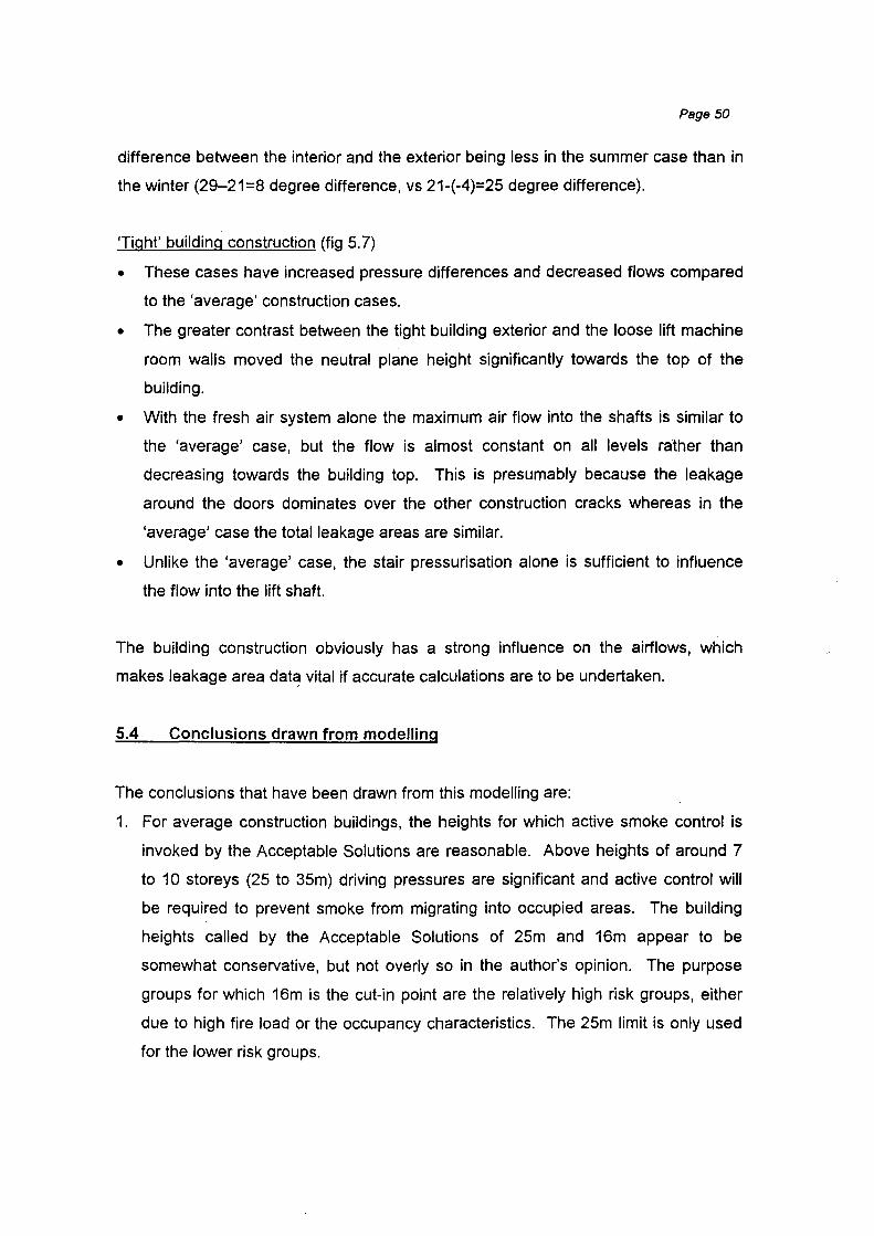
Page 50
difference between the interior and the exterior being less in the summer case than in
the winter (29-21=8 degree difference, vs 21-(-4)=25 degree difference).
'Tight' building construction (fig 5. 7)
• These cases have increased pressure differences and decreased flows compared
to the 'average' construction cases.
• The greater contrast between the tight building exterior and the loose lift machine
room walls moved the neutral plane height significantly towards the top of the
building.
• With the fresh air system alone the maximum air flow into the shafts is similar to
the 'average' case, but the flow is almost constant on all levels ralher than
decreasing towards the building top. This is presumably because the leakage
around the doors dominates over the other construction cracks whereas in the
'average' case the total leakage areas are similar.
• Unlike the 'average' case, the stair pressurisation alone is sufficient to influence
the flow into the lift shaft.
The building construction obviously has a strong influence on the airflows, which
makes leakage area dat~ vital if accurate calculations are to be undertaken.
5.4 Conclusions drawn from modelling
The conclusions that have been drawn from this modelling are:
1. For average construction buildings, the heights for which active smoke control is
invoked by the Acceptable Solutions are reasonable. Above heights of around 7
to 10 storeys (25 to 35m) driving pressures are significant and active control will
be required to prevent smoke from migrating into occupied areas. The building
heights called by the Acceptable Solutions of 25m and 16m appear to be
somewhat conservative, but not overly so in the author's opinion. The purpose
groups for which 16m is the cut-in point are the relatively high risk groups, either
due to high fire load or the occupancy characteristics. The 25m limit is only used
for the lower risk groups.
>.
c c
0 0 ·-
-[5t5 ro
::J .......,
s.... cnt>
-c
>.0
Q
) (.)
s.........., LO
.,--
O..c
Ci5.0> o
l-
"'"
0 0 N
' '
fig 5. 7 -Airflo
ws for a 10 storey building w
ith tight construction
' ,
'
' '
0 LO
.,--
0 .,--
' '
' '
,
'
(Bd
) 9Jn
SS
9Jd
LO
• ' . I
. I
"'' . c
. . . I
. . I I
I
. I
. c
c .
. .
·;-~
0 0 .,--0 LO
'
0
'{ ~
c
. ' \
. c c .
c
~· -
c .
c .
. c
v . c c . ...:.
j ; c . c
\
' '
r.· ;
I .
// ' c .
. '
' .
.
' I . I I
. c . -\
. ' \
' \
. -; \
' \ 0 0 LQ
( S/1) MD
I .:I
0 0 .,--1
0 .,--1
0 LO
.,--1
LO
.,--1
0 0 ~
0 .,--
CX)
1'-
(!)
LO
~
('()
N P
age 51
Q)
>
Q)
a.. 'U
.:= :.J
* a.. 'U
'-'(ij
- U')
0 ::: 0 1
;::
.:= :.J
t ::: 0 1
;:: '-co - U
')
t

Page 52
2. Below these heights, where precaution 9 is not invoked, the driving pressures are
small (<SPa) and smoke could be reasonably contained by passive means such
as door seals. However, it is apparent that any air system which pressurises the
fire floor must be shut off to prevent it forcing smoke into the shafts, unless stair
shaft pressurisation is also provided. If stair pressurisation is present, there may
be some merit in utilising the HVAC to enhance the building safety. This will
depend on the exact physical characteristics of the building and so should be
examined case by case.
3. The building construction has a significant impact on the air flows and pressures.
There are significant differences between the airflow patterns of average and
tight constructions. There is unfortunately little data available on leakage areas
and none (as far as the author is aware) relating to New Zealand construction
techniques. This is an area of future research which would be extremely
beneficial to refining the design of smoke control systems.
4. Systems for actively managing smoke in lift shafts are not addressed by the
Acceptable Solutions but are worthy of some consideration. The lift shafts are
obvious routes for transport of smoke and design philosophies to control this are
required. The current Acceptable Solutions make no allowance for this and only
attempt to contain the smoke (with lift lobbies, much to the ire of many architects)
or detect the presence of smoke if it should come out of the shaft into an
occupied floor. Lift shaft pressurisation could be considered as a viable
alternative to these measures.
5. In buildings with stair pressurisation systems, it is possibly beneficial to keep the
HVAC (or at least it's fresh air system) operating, to assist in preventing smoke
from exiting the lift shafts into the occupied spaces. This is another area which
would benefit from further research and testing.
Page 53
6. THE NZ BUILDING CODE AND THE APPROVED DOCUMENTS
6.1 The Document Structure
The legal requirements surrounding the construction and operation of buildings are
covered by the NZ Building Act 1991, which creates the Building Regulations and the
schedule entitled the NZ Building Code.
In the area of fire safety, the Building Code includes clauses C1, C2, C3 and C4.
These clauses lay out the objectives, functional requirements and performance
requirements to achieve the desired level of safety and protection for building
occupants, firefighters and neighbouring property. These (and all clauses in the
Building Code) are expressed in performance terms - they describe what is to be
done, not how to do it.
The Building Code clauses that are of interest in the area of fire safety are:
C 1 - Outbreak of Fire
C2 - Means of Escape
C3 - Spread of Fire
C4 - Structural Stability During Fire
Associated with each clause of the Building Code are the 'Approved Documents',
which contain 'Verification Methods' and 'Acceptable Solutions'. The Acceptable
Solutions provide a prescriptive, 'deemed to comply' method of satisfying the
requirements of the respective Building Code clause. Verification Methods describe
test methods which can be used to ascertain compliance with particular aspects of the
Building Code. There are currently no verification methods associated with C2, C3 or
C4. In the area of fire safety, the Acceptable Solutions C2/AS1, C3/AS1 and C4/AS1
are the principal focus of Territorial Authorities and designers for the majority of
commercial building situations.

Page 54
Alternative designs that are outside the framework of the Acceptable Solutions are
able to be used providing they can be shown to satisfy the Building Code objectives
and requirements.
In addition to the Building Code clauses and Acceptable Solutions there is also the
Fire Safety Annex, which contains the appendices to C2, C3 and C4. The Annex
contains (among other things) the basic design data for any particular building use
and configuration and is therefore the starting point for any analysis.
Clauses C1 and C4 do not contain requirements for HVAC systems. Clause C1 is
principally aimed at the installation of fuel-burning appliances (such as furnaces and
fireplaces) to minimise the likelihood of a fire occurring, and Clause C4 covers
structural aspects of buildings under fire conditions.
With respect to the aspects of ventilation in multistorey buildings as they apply to fire
safety, it is only particular provisions of clauses C2 and C3 which are relevant to this
discussion, although the analysis must inevitably include aspects from the Fire Safety
Annex.
6.2 Ventilation and Smoke Control Objectives and Requirements
The objectives, functional requirements and performance requirements that relate to
ventilation and smoke control in clauses C2 and C3 are:
C2: Objective C2.1 - The objective of this provision is to:
(a) Safeguard people from injury or illness from a fire while
escaping to a safe place, and
(b) Facilitate fire rescue operations.
Functional Requirement C2.2 - Buildings shall be provided with
escape routes which:
(a) Give people adequate time to reach a safe place without being
overcome by the effects of fire, and
(b) Give fire sen,ice personnel adequate time to undertake rescue
operations.
C3: Objective C3.1 - The objective of this provision is to:
(a) Safeguard people from injury or illness when evacuating a
building during fire.
(b) Provide protection to fire service personnel during fire fighting
operations.
Functional Requirement C3. 2 - Buildings shall be provided with
safeguards against fire spread so that:
(a) Occupants have time to escape to a safe place without being
overcome by the effects of fire,
(b) Firefighters may undertake rescue operations and protect
property
Performance C3. 3. 7 - Air conditioning and mechanical ventilation
systems shall be constructed to avoid circulation of smoke and fire
between fire cells
Performance C3.3.8 - Where an automatic smoke control system is
installed, it shall be constructed to:
(a) Avoid the spread of fire and smoke betweenfirecells, and
(b) Protect escape routes from smoke until the occupants have
reached a safe place.
Page 55
Page 56
6.3 The Requirements of the 'Acceptable Solutions' for HVAC Systems
The Acceptable Solutions C2/AS1 and C3/AS1 and the Fire Safety Annex contain the
requirements for smoke management by natural and mechanical ventilation wnich are
deemed to be required under certain circumstances. Parts of these requirements are
somewhat convoluted which makes them not particularly clear about their scope of
application, or how the requirements should be achieved when they are applied.
In particular, the areas that are dealt with in the Acceptable Solutions are:
Exitway pressurisation
Exitway natural ventilation
Atria and intermediate floors
Air handling systems
It is this last item which is applicable to HVAC systems in typical multistorey buildings
and is the principal subject of this discussion. Some comments are also made in
relation to natural ventilation of exitways.
The Acceptable Solution requirements for how an air handling system should behave
if a fire is detected, or even to which air handling systems the requirements apply, are
not clearly described. There is also one section that, if strictly applied, has some wide
implications on the type of alarm system installed.
The sections of the Acceptable Solutions that are relevant to ventilation are
summarised below:
The Fire Safety Annex
Table 81 in the Annex calls up the required firecell F rating, the associated alarm type
and the other precautions which are deemed to be appropriate to the firecell purpose
group, number of occupants and building height.
The requirements for ventilation systems (by natural or mechanical means) under fire
conditions appear in the following precautions from table 81:

Precaution 9
Precaution 1 0
Precaution 11
Precaution 13
Smoke control in air handling systems
Natural draught ventilation
Mechanical smoke control
Pressurisation of safe paths
These precautions are summarised below:
Precaution 9
Page 57
HVAC systems shall comply with the requirements for smoke control in C2/AS1
and C3/AS1. Activation may be initiated by either a self-contained detection
system or the main building alarm system.
Precaution 1 0
Natural draught smoke extraction, where a firecell is provided with a smoke
reservoir and with outlet vents and fresh air inlets to allow smoke movement by
natural draught (as described in C3/AS1, section 9.2). This precaution applies
only to common spaces in buildings with intermediate floors, (ie. Atria).
Precaution 11
As for precaution 10, but with mechanical ventilation instead of relying on the
natural buoyancy of the smoke (as described in C3/AS1, section 9.3). This
precaution also applies only to common spaces in buildings with intermediate
floors, (ie. Atria).
Precaution 13
Exitway pressurisation is to comply with AS1668.1, section 6 (sic)*.
Each of these precautions (and the others included in the Annex) are invoked for
buildings containing various combinations of purpose group, occupant numbers and
height.
It is Precaution 9, 'Smoke Control in Air Handling Systems', that is of interest here,
which is invoked by table 81 for the following occupancies and building heights:
• Presumably the reference in the document should be to AS1668.1, section 8 (not 6), as It is section 8 which covers stair pressurisation.
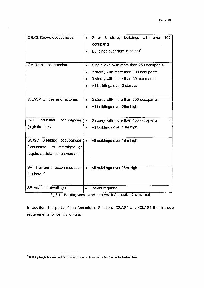
Page 58
CS/CL Crowd occupancies • 2 or 3 storey buildings with over 100
occupants
• Buildings over 16m in height"
CM Retail occupancies • Single level with more than 250 occupants '
• 2 storey with more than 1 00 occupants
• 3 storey with more than 50 occupants
• All buildings over 3 storeys
WUWM Offices and factories • 3 storey with more than 250 occupants
• All buildings over 25m high
WD Industrial occupancies • 3 storey with more than 1 00 occupants
(high fire risk) • All buildings over 16m high
SC/SD Sleeping occupancies • All buildings over 16m high
(occupants are restrained or
require assistance to evacuate)
SA Transient accommodation • All buildings over 25m high
(eg hotels)
SR Attached dwellings • (never required) .. . .
f1g 6.1 - BU1Idmgs/occupanc1es for wh1ch Precaut1on 9 IS mvoked
In addition, the parts of the Acceptable Solutions C2/AS1 and C3/AS1 that include
requirements for ventilation are:
• Building height Is measured from the floor level of highest occupied floor to the final exit level.

Page 59
C2/AS1 -Means of Escape
8 Smoke control
8.1 gives the general objectives, and refers to C3/AS1, paragraph 9.2 for firecells with
intermediate floors.
8.2 gives ventilation area requirements for natural ventilation of exitways for sleeping
purpose groups, where mechanical ventilation is not provided. (Note that the
alternative requirements for mechanical ventilation are not defined, however).
8.3 puts a smoke separation at mid height of stairways greater than 25m in height (if
not pressurised nor sprinklered).
C3/AS1 -Spread of Fire
7 Concealed spaces
7.1.1 and fig.14 have requirements for concealed spaces where these act as air
handling plenums.
9 Smoke Control
9.1 Exitways
9.1.1 states that the acceptable solution for natural ventilation of IE purpose
group exitways is given in C2/AS1 (presumably this refers to C2/AS1 para 8.2,
as mentioned above).
9.1.2 requires that where exitway pressurisation is required, it shall comply with
AS1668.1 section 8.
9.2 Firecells with intermediate floors
9.2.1 requires that firecells with intermediate floors include provisions for the
control smoke spread (refers to NFPA928- Smoke management systems in
malls, atria and large spaces for guidance).
9.2.2 covers horizontal smoke spread in large areas - refers to Morgan &
Gardner [1990] as an acceptable method of compliance.
9.2.3 for CM occupancies of more than 500 people, the smoke control system
is to be independent of other systems.

Page 60
9.2.4-9.2.11 cover requirements for smoke reservoirs and smoke baffles.
9.2.12 covers natural ventilation requirements.
9.3 Mechanical smoke control where intermediate floors are present (ie relates to
precaution 11 from the Fire Safety Annex)
9.3.1 gives the basic requirements.
9.3.2- 9.3.8 gives design parameters such as fire size, design velocities and
pressure differences.
9.4 Discusses sprinkler systems in relation to smoke baffles and tall spaces.
9.5 Mechanical smoke extraction in buildings with intermediate fl_oors is to be activated
by smoke detectors, with requirements for detector locations.
9.6 When smoke detection is activated, it shall start smoke control systems and shut
down other HVAC plant. (This paragraph appears to be out of place - this is
discussed further, below).
9. 7 Covers air handling systems in buildings without intermediate floors, and states
that AS 1668. 1 is acceptable to prevent smoke recirculation to other firecells via
the air handling system.
9.8 Emergency power requirements (where required by table 81).
9.9 Requirements for theatre stages.
6.4 Discussion of HVAC Aspects
Of all the sections noted above, the only ones which are apparently directly relevant
to HVAC systems in multi-storey buildings (ie a building without an atrium) are C3/AS1
sections 7.1.1, 9.6 and 9. 7.
The particular aspects discussed here are:
• Are the requirements of section 9.6 sensible?
• Are there other options suitable to comply with section 9. 7?
• Should C3/AS1 sections 9.6 and 9.7 apply to all HVAC systems, or only when
invoked by table 81?
• What are the implications of section 7 .1.1 and are they sensible?
Some comments are also made concerning the provision of mechanical ventilation to
satisfy C2/AS1 section 8.2.
Page 61
It needs to be noted at this point that each of the sub-sections of paragraph 9 apply to
a particular set of circumstances or conditions and effectively can be read in isolation
from the others.
6.4.1 C3 Paragraph 9.6 "Automatic activation of services plant"
This paragraph states:
The smoke detection equipment when activated shall:
a) Open all vents which are part of the smoke extraction and air
supply systems
b) Start smoke extraction and air supply systems, and exitway
pressurisation where installed
c) Turn off air-conditioning and mechanical ventilation plant
which is not required or designed for fire safety, and
d) Start the emergency power supply system used for fire
protection systems.
This paragraph appears to presuppose that these various features are fitted to the
HVAC systems. This raises questions about the intentions of the paragraph- whether
it intends to require these features to be fitted or if it only applies should they happen
to be already present.
As noted above, each of the sub-sections of paragraph 9 apply to a particular set of
circumstances or conditions and effectively can be read in isolation from the others.
However, I believe that this paragraph is not intended to stand alone, but applies
wholly to the previous paragraph, (9.5 - Smoke detectors in mechanical extraction
systems), which concerns the types of smoke detection systems used to activate
extraction systems in buildings with intermediate floors. All the other main paragraph
Page 62
headings of section 9 are able to read in isolation whereas para 9.6 is meaningless
when applied this way. It is, however, sensible when read in conjunction with 9.5.
I believe it should be renumbered to become 9.5.2, which will remove the confusion
surrounding its application.
6.4.2 C3 Paragraph 9. 7 11Air-handling Systems"
This paragraph states:
9. 7.1 Compliance with AS1668:Part 1 is an acceptable method of
preventing the recirculation of smoke through an air-handling system to
other firecel/s in buildings without intermediate floors.
This is the principal section of the Acceptable Solutions which applies to HVAC
systems in multistorey buildings, but it gives only the advice that AS1668.1 [SAA,
1991] is an acceptable method of compliance. What other methods are acceptable?
Is AS 1668 applicable in all situations? Does this paragraph apply to all air handling
systems, or only when precaution 9 (smoke control in air handling systems) has been
invoked?
To attempt to address these questions it is relevant to first look at the provisions of
AS1668.
AS1668 "The Use of Mechanical Ventilation and Air-conditioning in Buildings", Part 1
Fire and Smoke Control
AS1668.1 is a prescriptive document that covers smoke control in central plant and
individual air handlers that supply over 1 0001/s to a given firecell, including any group
of small air handlers that collectively exceed this volume, where it is invoked by the
local (Australian) building regulations. It therefore applies equally to central plant and
Page 63
unitary systems. It also notes, however, that central plant air handlers in buildings
with separate fire stairs are to comply, regardless of whether the local regulations
require smoke control to be fitted.
This standard includes two methods of smoke control which may be applied:
1. Purging smoke control
2. Zone smoke control
Purging
The purging method is only applicable with central plant systems and requires
that the air handler(s) serving the zone containing the fire floor are run to
achieve an extract rate of 6 air changes per hour from all floors in the zone,
with the air supply set to 50-85% of the extract rate. The extracted air (and
smoke) is exhausted to outside the building. No attempt is made to treat the
fire floor differently from any other floor.
Zone Smoke Control
Zone smoke control applies to either central plant or individual air handlers
(floor by floor units, in this context). The standard requires that the firecell is
kept at 20Pa below the surrounding areas and the exhaust rate achieved from
the fire zone is at least 6 air changes per hour. This is achieved by selectively
operating air control dampers on the various floors - on the fire floor the return
air damper is opened and the supply air damper is closed. On non-fire floors,
the opposite is done with the supply air dampers opened and the return air
restricted. This ensures that the pressure of the fire zone is below that of the
surrounding spaces.
The problem with using AS1668.1 as the means of compliance is that the methods of
purging and zone control are only possible with central plant or floor by floor systems.
The unitary systems (described in section 4 of this report) are incapable of the type of
operation required to achieve either zone or purging control, as they do not move air
into or out of the firecell but (mainly) recycle the air within it. As discussed in section
Page 64
4, the only air introduced from outside is via the fresh air system, which is insufficient
for the control regimes required by the standard.
It is also noted in the Literature Review section of this report that a purging system
alone is not regarded as satisfactory for fire safety. The commentary to AS1668.1
acknowledges that purging is less effective than zone control, but the method is still
included as it has the advantage of simplicity, which therefore also increases the
reliability.
What alternative means of compliance are available?
NFPA 90A and 92A
In the USA, the documents NFPA 90A, "Standard for the Installation of Air
Conditioning and Ventilating Systems" and NFPA 92A "Recommended Practice for
Smoke Control Systems" [NFPA 1993] provide good general discussion of many
HVAC system types, with sensible installation standards and describe pressure
control methods similar to the zone control of AS1668, but in more general,
performance based terms. The action recommended for unitary systems is to shut
the system down.
The principal hindrance to the utilisation of the NFPA documents in New Zealand is
that they cross-refer to NFPA or other US standards in many instances. They could
however provide a base for formulating an alternative solution.
Page 65
Shutting off
As an alternative to AS1668, the compliance method most often employed is simply to
shut off the HVAC system when a fire alarm occurs, as was the normal practice since
the 1930's. This is employed for all types of HVAC system- central plant and unitary.
In smaller buildings this is probably acceptable, but for tall buildings there is the
possibility that shutting off the air conditioning will allow the natural air flows (due to
stack effect) to assist smoke to travel to occupied areas remote from the fire, more
than if the HVAC was not shut down. This was discussed further in Section 5
Recommendations
For tall buildings with suitable systems there is no doubt that active smoke
management by zone control methods is the best solution, but for other (unitary)
systems, the modelling discussed in Section 5 suggests that shutting off the HVAC I
may not be the best solution in all circumstances. In tall buildings with stair
pressurisation systems, also keeping the outside (fresh) air system operating may
assist in preventing smoke from entering remote floors via lift shafts and other vertical
smoke paths.
The modelling discussed in Section 5 was not exhaustive and some of the basic
design data necessary for an in-depth study is not available for New Zealand
conditions. This is an area which could be the subject of more analysis.
The modelling also suggests that natural smoke movement around a low level
multistorey building is due to driving forces which are small enough to be overcome by
passive means (eg smoke seals on doors) whereas for taller buildings an active
smoke management system is required. This leads to the conclusion that the
Acceptable Solutions invoke Precaution 9 at levels which are generally reasonable,
and that active smoke control using the HVAC system is probably unnecessary in
lower buildings.

Page 66
The author's recommendation is therefore that active smoke control measures should
be put in place whenever Precaution 9 is invoked, but in other situations the shutting
down of the HVAC is sufficient. Buildings with unitary systems that require active
smoke control may need to have additional dedicated equipment to achieve this.
6.4.3 C3 Paragraph 7.1.1 "Cavity within firecells"
This paragraph states:
An upper cavity space acting as an air handling plenum (see Figure 14)
may extend over more than a single lower space if all the following
requirements are satisfied:
a) The upper cavity space shall not extend into another firecell
except as permitted in Para 7.1.2 {which requires fire-rated
closures},
b) An automatic fire detection and alarm system is fitted
throughout the firecell, with detectors in the cavity and in all
return ducts,
c) Detector activation automatically causes the ventilation
system to switch from circulation to extract, as required by
Para 9.6.1,
d) The ceiling and its supports and surfaces within the cavity are
non-combustible,
e) Electrical wiring is laid in metal trays, and
f) The SF! and SDI of any pipe insulation or acoustic insulation
comply with the requirements of Table 4.
The sketch accompanying this paragraph, (Figure 14, shown below as fig 6.2), is
intended to clarify the requirements. Note that it specifically mentions smoke
detectors, rather than the fire detectors included in the text, and also depicts a plenum

Page 67
supply, ducted return configuration which is very unusual. The result is that the figure
confuses more than it clarifys.
Two possible objectives can be surmised for this paragraph -
(1) to prevent smoke from a fire in one occupied space being transported into another
occupied space via the ceiling void and air handler, or
(2) to prevent smoke from a fire located in the cavity from being transported into the
occupied spaces below.
The apparent principal objective of this paragraph can be deduced from the
requirement that it applies only to cavities which extend over more than one lower
space. The objective would therefore appear to be to prevent smoke spread from one
room to another. However, the other requirements of non-combustible ceiling
construction, pipe insulation SFI and SDI limits and electrical cable trays imply that a
fire originating within the ceiling void is the danger.
For the purposes of this discussion, both possible objectives are examined.
Smoke detectors in cevi/y end return eir d.Jct. Automatic Ire
detection end elerm system
c:::::;;;~~==5~~~==t~~~~~==~~-~~I/Y~ou~gh~out the lirecet
Spaces beiow cavity
Floor slab
above
Ceilir1g
r----1--CAV/TY AND
fig 6.2 - Figure 14 from Paragraph 7 .1.1 of C3/AS1
SPACES FORM ONE FIRECELL
(Note that this paragraph exceeds the performance requirements of clause C3, which
requires that smoke spread between firecells is prevented. However, this paragraph
seeks to prevent smoke spread between spaces within the firecell.)
Page 68
What are the implications of this paragraph?
Ceiling plenums are commonly used as air return paths in both unitary and central
plant systems. Strictly applying this paragraph requires that whenever the ceiling void
is used in this manner and it covers more than one room below, then in-ceiling fire
detection must be fitted (smoke detection, if fig 14 is strictly applied) even if the fire
alarm standard NZS4512 does not require it. (Indeed, it is possible that the building
did not previously have a requirement for an alarm system to be.installed at all!)
Also, there is an implied requirement that the air system is to be capable of operating
in an extract mode.
As it is more likely than not that an air system will include more than one room, it is
very likely that the requirements of this paragraph will be invoked.
It also needs to be noted that the installation of smoke detection within a ceiling void
is contrary to the recommendations of most alarm equipment suppliers, due to the
frequency of false alarms caused by dust in these areas.
How can the requirement be complied with?
Apart from the installation of all the items listed in b) to f), the simplest method
employed to comply with this requirement is to avoid using the ceiling plenum as an
air return path and installing ductwork to carry the air back to the air handler. This can
be a severe limitation on the HVAC system designer and has an obvious cost penalty
in the additional ducting required (though possibly less so than items b to f) as well as
significantly reducing the flexibility of the system to cater for altering uses of the
spaces below.
It also does nothing to prevent the transport of smoke from one room to another via
the air handler which was one of the deduced objectives of the paragraph.
Page 69
It could also be argued that this will exacerbate the situation if a fire should start within
the ceiling void, as detection will be delayed as there is possibly no detection system
fitted and no way of the early fire effects being noticed by the occupants (eg a smell
of smoke)
Are the objectives of the paragraph sensible?
In the author's opinion, the deduced objectives are sensible, but the method of
execution is not.
Preventing the transport of smoke from one room to another via the air system is not
achieved by this paragraph. As mentioned above, strict compliance is achieved by
utilising a fully ducted system, but this does nothing to prevent the transmission of
smoke. In fact it could be argued that it will exacerbate the situation by reducing the
amount of dilution that would be achieved by the air passing through the much bigger
ceiling void.
The danger of smoke from a fire originating within the ceiling void is real and would be
diminished by the measures invoked. However, the danger is just as real whether the
ceiling void covers more than one space or not. Also, as discussed in section 3.4,
fires resulting from air conditioning equipment are very rare.
The question of provision of detectors within the ceiling void is, I believe, already
adequately covered by NZS4512 (the fire alarm system standard) and NZS4541 (the
sprinkler standard), but the requirements for non-combustible ceiling construction is
sensible, as are the SFI and SOl requirements for materials used within the cavity.
The requirement for electrical wiring to be laid in metal cable trays is somewhat
unnecessary and it should be sufficient that the wiring is adequately supported clear
of the ceiling members and other equipment (eg on catenary wire) as is good trade
practice anyway.

Page 70
How could it be improved?
I believe the paragraph should clearly indicate the requirements for allowing the use of
the ceiling void as an air path, regardless of whether it covers more than one lower
space, but leave the provision of in-ceiling detection to the alarm or sprinkler
standards, as appropriate.
My recommendation is to extend the scope to apply to all uses of the ceiling cavity as
air handling paths, but to make the requirements reasonable.. The wording of this
paragraph should be amended to read:
An upper cavity space may be used as an air handling plenum if all the
following requirements are satisfied:
a) The upper cavity space shall not extend into another firecell
except as permitted in Para 7.1.2,
b) The ceiling and its supports and surfaces within the cavity are
non-combustible,
c) Electrical wiring is adequately supported clear of the ceiling
members and other equipment, and
d) The SF! and SDI of any materials used such as pipe insulation
or acoustic insulation comply with the requirements of Table
4.
6.4.4 C2 Paragraph 8.2 "Ventilation in enclosed exitways for purpose groups
SC, SD, SR ·and SA"
This paragraph gives the requirements for opening areas for natural ventilation in
exitways that serve more than one household suite, where "pressurisation or
mechanical ventilation is not provided". The requirements for pressurisation are well
defined elsewhere in the Acceptable Solutions, but the difficulty that is introduced by
Page 71
this section is that it does not define the extent of mechanical ventilation which is
adequate to substitute for natural ventilation.
Building Code clause G4 covers ventilation, and refers to NZS4303 "Ventilation for
Acceptable Indoor Air Quality". This gives the minimum air flows which are to be
delivered into a space to maintain reasonable conditions of freshness. For an internal
corridor space such as an exitway this minimum is 0.251/s/m2, which equates to an air
change rate of about 0.35 - 0.4 air changes per hour (based on a normal ceiling
height of 2.4m). For comparison, continuously occupied spaces require fresh air rates
of around 1 .5 air changes per hour.
How does this compare with the ventilation that would be expected from the opening
areas required by para 8.2?
The areas for natural ventilation which are called up by this section are:
Stairways - 1 .5m2 at both top and bottom, or 2.5% of plan floor area at each
level
Horizontal paths - 1 .5m2 or 5% of floor area, arranged so that approximately
two thirds of the area is at the top.
To make some estimate of the natural air flow rates that would be achieved by these
areas, a variety of stair heights, floor areas and internal/external temperature
differences were modelled using CONTAM96 [Walton, 1993]. The resulting air flows
are summarised in table 6.2, below. Air flows are given in both litres per second and
air changes per hour.
The modelling indicates that the air change rates that would be expected due to the
areas defined by section 8.2 significantly exceed the minimum requirements of
NZS4303. Large temperature differences are probably unusual in most New Zealand
locations, but even differences of 2 or 5 degrees are sufficient to induce air change
rates of 4 to 10 changes per hour, if not more.
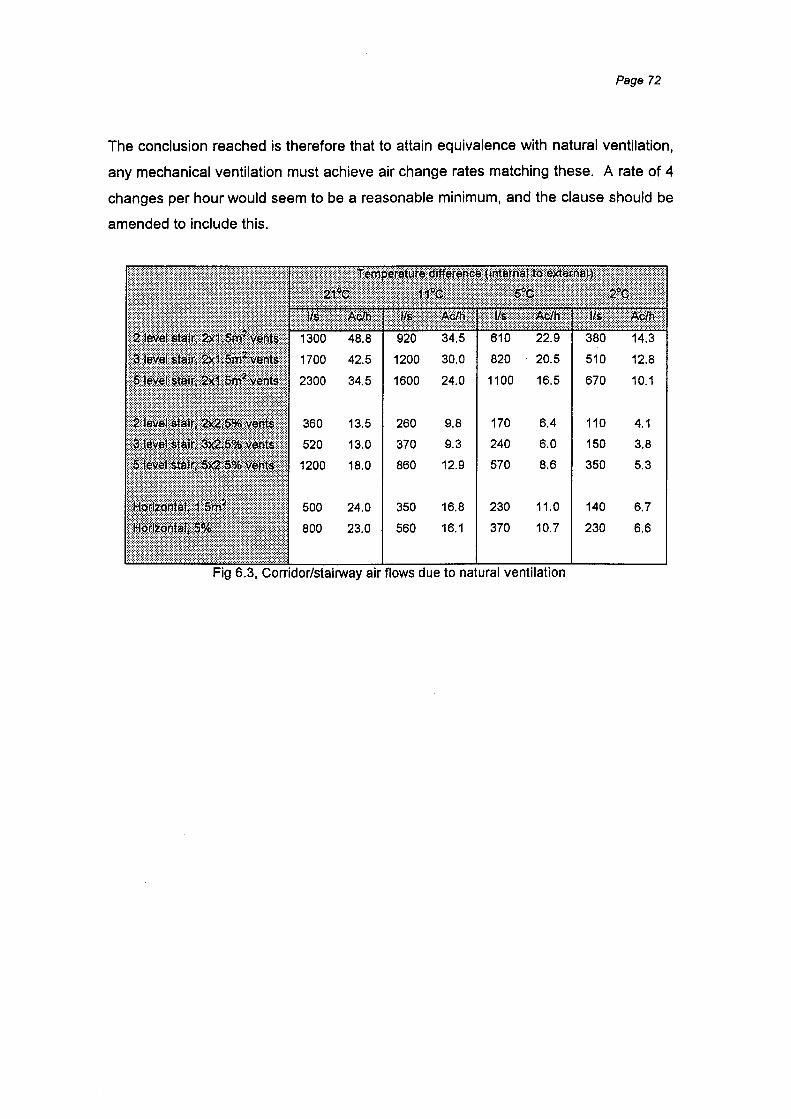
Page 72
The conclusion reached is therefore that to attain equivalence with natural ventilation,
any mechanical ventilation must achieve air change rates matching these. A rate of 4
changes per hour would seem to be a reasonable minimum, and the clause should be
amended to include this.
1200 30.0 820 510 12.8
34.5 1600 24.0 1100 16.5 670 10.1
360 13.5 260 9.8 170 6.4 110 4.1
520 13.0 370 9.3 240 6.0 150 3.8
1200 18.0 860 12.9 570 8.6 350 5.3
500 24.0 350 16.8 230 11.0 140 6.7
800 23.0 560 16.1 370 10.7 230 6.6
air flows due to natural ventilation
Page 73
7. CONCLUSIONS
In many fires, the fatalities that occur are often due to the effects of smoke rather than
from direct contact with the fire. HVAC systems in multistorey buildings can be used
to actively manage the smoke produced by a fire, but they can equally be instrumental
in transporting smoke to areas which endanger the occupants, if the HVAC controls
respond inappropriately to the alarm. An understanding of both the nature and
volumes of smoke produced and the characteristics of various HVAC systems is vital
for the Fire and HVAC Engineers to work together to build safe ~ystems.
This report has described some simple equations to enable the HVAC Engineer to
appreciate the large volumes of smoke that can be produced by even relatively small
fires.
For the benefit of the Fire Engineer, the various types of HVAC systems that are
commonly found in New Zealand multistorey buildings have been described, with an
emphasis on how the systems may be appropriate in a smoke control situation. The
systems have been generally categorised as 'Unitary' or 'Central Plant', depending on
their ability to deliver air from outside the occupied space or firecell.
Particular aspects of the Building Code Acceptable Solutions that are relevant to
HVAC systems in multistorey buildings have been discussed, concentrating on
aspects which are not particularly clear in their application or objectives. Specific
recommendations for amendments to the current Acceptable Solutions are:
C3/AS1 clause 9.6
This clause is confusing because (at first glance) it is intended to stand alone,
as do the other clauses in section 9 of C2/AS1. However, on examination it
does not make sense unless it is read as a continuation of the previous clause.
The recommendation is that the text is made to be clearly part of the preceding
clause by a simple renumbering.
Page 74
C3/AS1 clause 9.7
As the main clause covering the fire behaviour of HVAC systems in multistorey
buildings, this clause only states that AS1668.1 may be used as a means of
compliance. It does not make compliance with AS1668.1 mandatory, nor are
other options given, and it is not even clear whether the clause applies to all
HVAC systems or only when precaution 9 has been invoked by the Fire Safety
Annex. A frequently used option is to simply shut the HVAC down on a fire
alarm.
Computer modelling of air flows in typical buildings suggests that active smoke
control is necessary in buildings for which precaution 9 is required '(generally
tall buildings), but for smaller buildings the shutting off of the HVAC is probably
sufficient. Active control could be compliance with AS1668.1 or NFPA90A and
92A. For tall buildings fitted with unitary type systems some form of separate
smoke control equipment will probably be required, as the HVAC plant is likely
to be incapable of providing the air flows necessary.
The modelling also suggests that for buildings fitted with stair pressurisation
systems there may be some merit in not shutting off the HVAC, to assist in
preventing smoke from using lift shafts and other risers to enter floors remote
from the fire. This is an area where further data and analysis is required
before definitive conclusions can be reached.
C3/AS1 clause 7.1 ;1
Clause 7.1.1 contains requirements for concealed (ceiling) spaces that extend
over more than one lower space if they are to be used as air handling
plenums. The objective of the clause is not clear and the requirements are (in
the author's opinion) excessive. The recommendation is that the clause is re
written to give a clear objective and to provide reasonable requirements. A
suggested revision to the text is given.
C2/AS1 clause 8.2
This clause contains a requirement that natural ventilation to exitways should

Page 75
be provided when no pressurisation or mechanical ventilation exists. The
criteria for pressurisation are well defined but equivalent rates of mechanical
ventilation are not defined anywhere. Computer modelling was carried out to
assess the air change rate that the specified natural ventilation areas would
achieve under a variety of ambient conditions.
The modelling indicates that an air change rate of at least four changes per
hour would be achieved by natural ventilation. The clause should be amended
to require natural ventilation if neither pressurisation nor mechanical ventilation
of this air change rate is provided.
The results of some computer modelling of air flows around typical multistorey
buildings are presented in Section 5. The modelling indicates that the normal HVAC
airflows may be suitable to influence smoke flows under some conditions, but it is
dependent on accurate data on building element leakage rates. The data that is
available on building elements is sparse, and none of it applies specifically to New
Zealand conditions and building techniques. This is an area of further research that
would be very useful to pursue.

8. REFERENCES
ASH RAE
Beyler,C. L.
BIA
Brundrett, G.
Fundamentals Handbook
Fire Plumes and Ceiling Jets
NZBC Approved Documents -
C2: Means of Escape
C3: Spread of Fire
C4: Structural Stability During Fire
Building Pressure
Brundrett, G.; Building Airtightness: Standards
Jackman, P.; and Solutions
Jones, P.;
Liddament, M.;
Perera, E
Buchanan A. H. Fire Engineering Design Guide
(ed)
Butcher, E. G.; Smoke Control in Fire Safety
Parnell A. C. Design
Chapman, E. F. HVAC ... and the Fire Chief.
Page 76
Ch 23, ASHRAE Fundamentals Handbook,
American Society of Heating ,
Refrigerating and Air-Conditioning
Engineers, 1989.
Fire Safety Journal, No 11, 1986
Building Industry Authority, 1995
Building Services Journal, Chartered
Institution of Building Services Engineers,
September 1997
Building Services Journal, Chartered
Institution of Building Services Engineers,
September 1997
Centre for Advanced Engineering, 1994
E & F Spon, London, 1979
New York City Fire Dept. Fire Service
Today, Vol. 50, No. 11, November 1983.

CIBSE
Heskestad, G.
Klote, J. H.
Klote, J. H.
Klote, J. H.
Klote, J. H.
Klote, J. H.;
Budnick, E. K.
Klote, J. H.;
Clark, J. A.
Klote, J. H.;
Cooper, L. Y.
Fire Safety Engineering
Fire Plumes
Air Moving Systems and Fire
Protection.
Fire and Smoke Control: An
Historical Perspective.
Page 77
Section B5, CIBSE Guide, Chartered
Institution of Building Services Engineers,
1986.
The SFPE Handbook of Fire Protection
Engineering; 2nd edition; sect 2-2; 1995.
National Institute of Standards and
Technology, Gaithersburg, MD NISTIR
5227; July 1993.
National Institute of Standards and
Technology, Gaithersburg, MD ASHRAE
Journal, Vol. 36, No. 7, July 1994.
Inspecting and Testing Air Moving National Bureau of Standards,
Systems for Fire Safety. Gaithersburg, MD, Heating/Piping/Air
Conditioning, April 1988.
Smoke Control
Capabilities of Smoke Control:
Fundamentals and Zone Smoke
Control.
Smoke Control
Model of a Simple Fan-Resistance
Ventilation System and Its
Application to Fire Modelling.
The SFPE Handbook of Fire Protection
Engineering; 2nd edition; sect 4-12; 1995.
National Institute of Standards and
Technology, Gaithersburg, MD, Hughes
Associates, Inc., Wheaton, MD, Journal of
Fire Protection Engineering, Vol. 1, No. 1,
1-10, January/March 1989.
Ch 47, ASHRAE HVAC Applications
Handbook, American Society of Heating ,
Refrigerating and Air-Conditioning
Engineers, 1991.
National Institute of Standards and
Technology, Gaithersburg, MD, David
Taylor Naval Ship, Annapolis, MD, NISTIR
89-4141; 1989.
Klote, J. H.;
Milke, J. A.
Milewski, L.
Morgan, H. P.;
Gardner, J. P.
Narayanan, P
Narayanan, P
NFPA
NFPA
NFPA
Design of Smoke Management
Systems.
Control Safety Considerations for
HVAC Smoke Management
Techniques.
Design Principles for Smoke
Ventilation in Enclosed Shopping
Centres.
Smoke Control in Multi-storey
Buildings
Effectiveness of Smoke
Management Systems
Fire Protection Handbook (181h
edition)
NFPA90A - Standard for
Installation of Air Conditioning and
Ventilation Systems
NFPA92A- Recommended
Practice for Smoke Control
Systems
NZ Fire Service 1993-1997 Emergency Incident
Statistics
Peters, D. C. J. HVAC Systems for the Fire
Protection Engineer.
Page 78
American Society of Heating, Refrigerating
and Air-Conditioning Engineers; Society of
Fire Protection Engineers; 1992.
American Society for Testing and
Materials. Fire Safety: Science and
Engineering. f.STM STP 882. June 26-27,
1984, Denver, CO, Harmathy, T. Z., Editor,
1984.
BRE Report 186, 1990.
Study Report No 50, BRANZ, 1993
Study Report No 66, BRANZ, 1993
National Fire Protection Association
National Fire Protection Association, 1993
National Fire Protection Association, 1993
NZ Fire Service, 1998
Carrier Air Conditioning Co., Syracuse, NY
Fire Safety Journal, Vol. 7, No. 1, 65-80,
1984.
Purser, D. A.
Rye, G. S.
Semple, J. B.
Standards
Association
Australia
Standards
Australia I
Standards NZ
Taylor, R. E.
Walton, G. N.
Toxicity Assessment of
Combustion Products
Fire Protection and the Interface
with the HVAC System.
Smoke Control: How HVAC Can
Reduce Smoke and Fire Losses.
AS1668.1:1991- The Use of
Mechanical Ventilation and Air-
Conditioning in Buildings, Part 1,:
Fire and Smoke Control
DR 96503 - The Use of Ventilation
and Air-Conditioning in Buildings,
Part 1: Fire and Smoke Control in
Multi-compartment Buildings
Newest Firefighter: The HVAC
Engineer.
CONTAM93 User Manual (with
CONT AM96 updates)
Page 79
The SFPE Handbook of Fire Protection
Engineering; 2"d edition; sect 2-8; 1995.
Honeywell Inc., Minneapolis, MN Fire
Safety Journal, Vol. 7, No.1, 81-86,1984.
Smoke/Fire Risk Management,
Warrington, VA Building Standards, Vol.
48, No. 4, 6-9,45, July/August 1979 AND
Heating/Piping/Air Conditioning, Vol. 49,
No. 10, 61-66, October 1977.
Standards Australia
Standards Australia I Standards NZ; Draft
standard for comment, 1996
SUBSEQUENTLY WITHDRAWN
Smoke Control Assoc., Cleveland, OH
Heating/Piping/Air Conditioning, Vol. 54,
No. 4, 85-89, April 1982.
Building and Fire Research Laboratory,
National Institute of Standards and
Technology, 1993
Page 80
APPENDIX A- LIST OF FIGURES
2.1 Locations of deaths on upper floors where the fire was on floor 1
3.1 Smoke plume mass flow comparison
3.2 Typical leakage areas for walls and floors of commercial buildings
4.1 Airflows for a fan coil unit system
4.2 Airflows for an induction unit system
4.3 Airflows for a variable air volume system
4.4 Airflows for a constant volume system
4.5 Airflows for a dual duct system
5.1 Airflows for a 10 storey building with stack effect alone
5.2 Airflows for a 10 storey building with stack effect and fresh air
5.3 Airflows for a 10 storey building with stack effect and stair pressurisation
5.4 Airflows for a 1 0 storey building with stack effect, fresh air and stair
pressurisation
5.5 Airflows for a 20 storey building with stack effect alone
5.6 Airflows for a 10 storey building with 29°C ambient
5. 7 Airflows for a 1 0 storey building with tight construction
6.1 Buildings/occupancies for which Precaution 9 is invoked
6.2 Figure 14 from paragraph 7.1.1 of C3/AS1
6.3 Corridor/stairway air flows due to natural ventilation

Page 81
APPENDIX B - MODELLING RESULTS
The graphs that follow give the air flows and pressures calculated for the various
building configurations and conditions discussed in Section 5. The air flows are in
litres per second and the pressure differentials are in Pascals. The modelling was
carried out using "CONTAM96" [Walton, 1993)
In all cases the sign conventions used are positive air flows are from the occupied
space into the riser shafts and positive pressure differences result in positive air flows.
Level 1 is the ground floor.
A complete discussion of the modelling carried out is in Section 5, but in summary, the
features which were kept common to all of the buildings were:
• Floor plate size - each floor was kept at 800m2 with a perimeter of 120m (ie a 30m
square building with a .100m2 core).
• Floor to floor height of 3.5m.
• Stairwell- each building had a stair core of 16m2 and a perimeter of 16m, with the
ground level stair doors opening to outside.
• Lift core - each lift car was taken as occupying a 3x3m space (ie a three lift group
took up 27m2 and had a perimeter of 24m).
e Roof- at the roof level of each building was a lift machine room (LMR) and the top
of the stairwell. The LMR floor area was four times the size of the lift shaft below.
Each lift had a 0.09m2 rope penetration to the shaft below and the LMR was linked
to the stairwell by a single door. The stairwell also had a single door to the
outside.
• On the ground floor, two doors went to the outside and also the stairwell was
linked to the outside by two doors.
• The building fabric was taken as being of 'average' construction tightness as
defined by Klote (1995), except for roof LMR construction which was taken as
being 'loose'. A limited series of calculations were also performed for 'tight'
construction.
• Stair doors were taken as having a 3mm crack all round, with lift doors and ground
floor entry doors having a 6mm gap all round.
Page 82
Interior temperatures were set at 21°C (normal for office environments) with external I
temperatures of -4°C except for one set of calculations with a 29°C external
temperature.
Index to graphs
1. 3 storey building, stack effect only
2. 7 storey building, stack effect only
3. 10 storey building, stack effect only
4. 20 storey building, stack effect only
5. 3 storey building, fresh air only
6. 7 storey building, fresh air only
7. 10 storey building, fresh air only
8. 20 storey building, fresh air only
9. 3 storey building, stair pressurisation only
10. 7 storey building, stair pressurisation only
11. 10 storey building, stair pressurisation only
12. 20 storey building, stair pressurisation only
13. 3 storey building, fresh air and stair pressurisation
14. 7 storey building, fresh air and stair pressurisation
15. 10 storey building, fresh air and stair pressurisation
16. 20 storey building, fresh air and stair pressurisation
17. 10 storey building, stack effect only, tight construction
18. 10 storey building, fresh air only, tight construction
19. 10 storey building, stair pressurisation only, tight construction
20. 10 storey building, fresh air and stair pressurisation, tight construction
21. 10 storey building, stack effect only, 29 degree outside ambient
22. 10 storey building, fresh air only, 29 degree outside ambient
23. 10 storey building, stair pressurisation only, 29 degree outside ambient
24. 10 storey building, fresh air and stair pressurisation, 29 degree outside
ambient
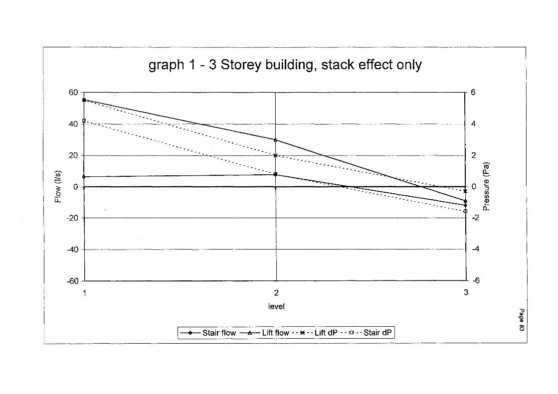
-C/) :::::: ......... 3: 0
1..1..
graph 1 - 3 Storey building, stack effect only
60 6
40 - - . . -- . . - - 4
20 1 --. .. , ........... I 2 . . . . -- ·---- .. _ ............... -ro
0 t "•i -~ ~ -~ 0~ ---- ··-- ::J
····-------._ ~ -. -'-a..
-20 -2
~0 ~
~0 ~
1 2
level
I • Stair flow .&. Lift flow - -*- -Lift dP - - o --Stair dP J
3
;;? ~ e
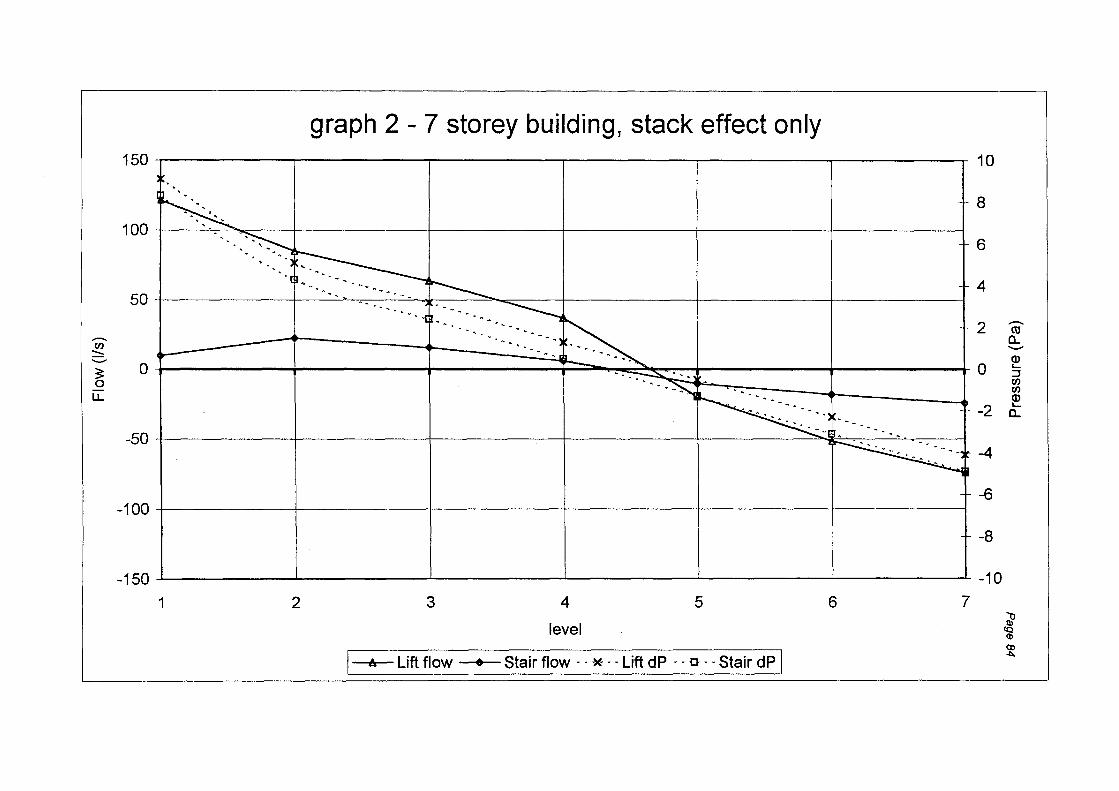
............ en
:::::: ......... ~ 0 u..
graph 2- 7 storey building, stack effect only 150.-----------r---------~----------~----------~----------~--------~
100 ·=l--+-H-r-= .. :::~~-.·---- ... _
50
10
8
6
4
2 -.. --.'-' ~-- ... --- .. ---
--···-·-·--.:~-·· ~
0 0 -
-50
-2 '···r=:::: -~ ~ ·::: ~: ~ ~: -~------.. . - . -
~ -4 -
-100t---------t---------+---------+---------+---------~------__J -6
-8
-150 -10 1 2 3 4
level
5
I A Lift flow • Stair flow - - * --Lift dP _-_~o --~tair dP]
6 7
............ cu a. -Q) ..... :::J en en Q) ..... a.
;;? ~ ~
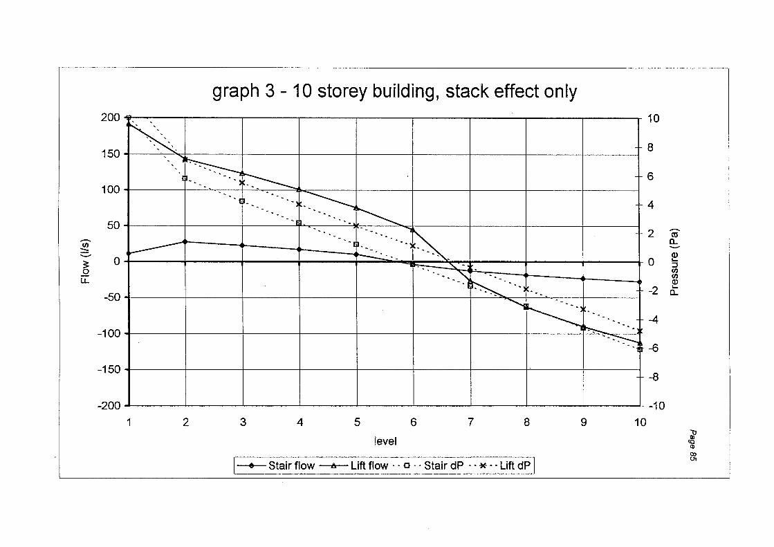
graph 3 - 10 storey building, stack effect only 200
' '
150
100
50
-en ::::: - 0 3 0 u.
-50
-100
K. ··~
'~~. ' ' . ' .. ,r-:----._ . . . • . • I . • ..... : . • •> • ·~r--...__
·.1 ·- -- -.,~ ····-- .. ~ .. -·-. ___ _
~ ···... . , .. .. --. ' -"\~----. . .. ~ ...
... .. ..4o . - . ~ --., !'--._ J ',
I ~~----._ ... --:--:-..,
-150 _j_
-200
1 2 3 4 5 6 7 8 9 10
level
I • Stair flow Lift flow ~-- o · · Stair dP ·~ - * -- Lift dP 1
10
8
6
4
2
0
-2
-4
-6
-8
-10
-ro a.. -Q) ..... ::J en en Q) ..... a..
l Q)
<XI 01
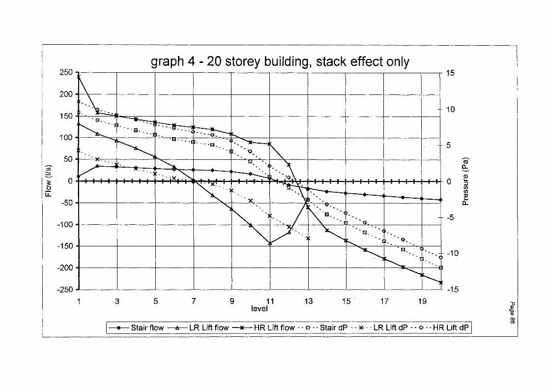
250
200
150
100
50 .......... en
::::::: ..._..
~ 0 0 u.
-50
-100
-150
-200
-250
1 3
graph 4- 20 storey building, stack effect only
5 7 9 11 level
13 15 . 17 19
15
10
5 .......... tU a.. -Q)
0 '-::J en en Q) '-a..
-5
-10
-15
I- -;-Stair flow ts LR Lift flow _• _1--!R Lift flow -- D--- Stair dP.-- *-- LR Lift dP -- o-- HR Lift dP-j
l CD
~

graph 5- 3 storey building, fresh air only
00 12
aaF' ~~~==±=---~ 70 (:: : : : : : : : : : : : : : : : : : : : : : : : : : : : : : : : : : : : : : :: .... : : : l : : : :: : : . . . . . . . . . . J 1 0
.... .............. ·- ................. _ --- .. - .. -60 ........ ' . ' . - - . .. - - - - - - - 8 .. ~ ......... -ro
. ~ ..... a.. -- (]) ..!!! 50 6 s
;:::.. V)
~ ~ 0 ~ u. 40 ---------- 4 a.
30-\ ~
20~ 10
2
0 0
1 2
level
I • Stair flow A lift flow ·· ·· ·)(· .. ·· Lift dP ~ -~afrdP ]
3
~ (Q (I)
Q) .....,

graph 6- 7 storey building, fresh air only 100 10
-··---. ~ --------..m 0
-2
-4
-6
-8
-10
3 4 5 6 7
level r·ul. Lift flow • Stair flow-- o-- Lift_<!~ -~*--Stair dP]
l (I)
Q) Q)

-VJ :::: .......... :; 0
LL
graph 7- 10 storey building, fresh air only 150~-----------,---------------,------------,~-----------r---------------r------------.---------------~----------~---------------~
50
01----
-50
~ " -·• ... ~ . "*- ... -.... ~ - ··ljl .• - ..•. - - • - • - • - • - -
...... --"' •• # ... -
--~
-100~----~------~------r------r------+------+------+------+----~
10
8
6
4
2
0
-2
-4
-6
-8
-150 -10 1 2 3 4 5 6 7 8 9 10
level
J e Stair flow t. Lift flow · · o ··Stair dP ·~*--Lift -dP-]
-CCI a_ -Q) '-:J VJ VJ Q) '-a_
~ ~ Q) (()

graph 8- 20 storey building, fresh air only 200 10
150 8
6 100
4
50 2 -(/)
::::: ~
3 0 0 0
LL
-50 -2
-4 -100
-6
-150 -8
-200 -10
1 3 5 7 9 11 13 15 17 19 level
] e Stair flow ~R Lift flow • HR Lift flow ·· .. o .... Stair dP · · * · · LRU~ · <> · ~HRlift dP]
-Cll 0... -Q) '--::J (/) (/) Q) '--
0...
~ ~ co 0

50
40
30
20
.-. 10 rJ)
:::: .......... 3: 0 0 u.
-10
-20
-30
-40
-50
1
graph 9- 3 storey building, stair pressurisation only
--~ .... -._
.............. .... -.... .. .. -..
... ... -..... - .........
~ ~ ~
--, "--- ... ___________ , ...
2
level
------- .......... ~
··--------~
3
I e Stair flow A Lift flow · · * · · Lift d~-0.-=-=5talrdP ]
5
4
3
2
1~ -Q)
0 :s rJ) rJ) Q)
-1 ct
-2
-3
-4
-5
i <D co _...
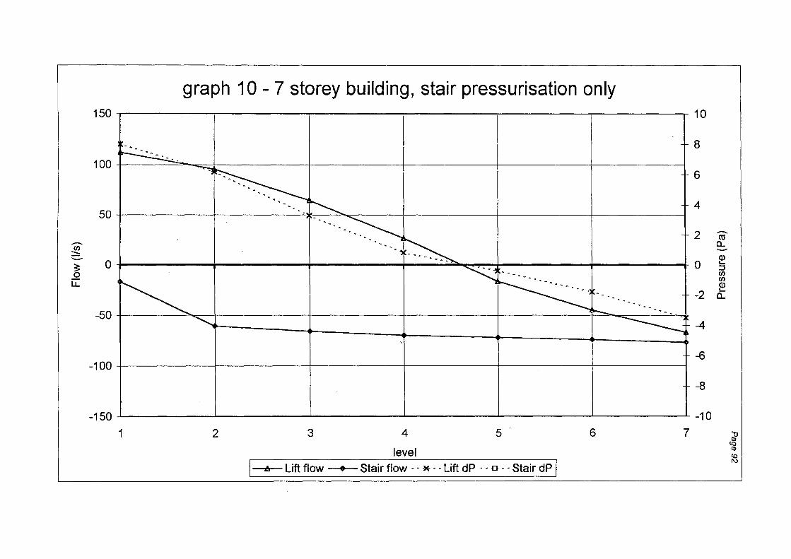
graph 10 - 7 storey building, stair pressurisation only 150 10
. -. 8
50
......... ~ -~ 0 0
LJ..
-50
~ . ~
~ ~ -------~
~ •• 'l
-~
~ ~ .
~-- ... ·--- ... ........... ~
6
4
2 ......... ro a.. -(J)
0 ,_ ::J C/) C/) (J)
-2 ,_ a..
-4
100
'
-6 -100
-8
-150 -10
1 2 3 4 5 6 7 i en
~ level
I Stair flow · · *----=-=-l_ift-dP ~~- ~----= ·Stair dP I
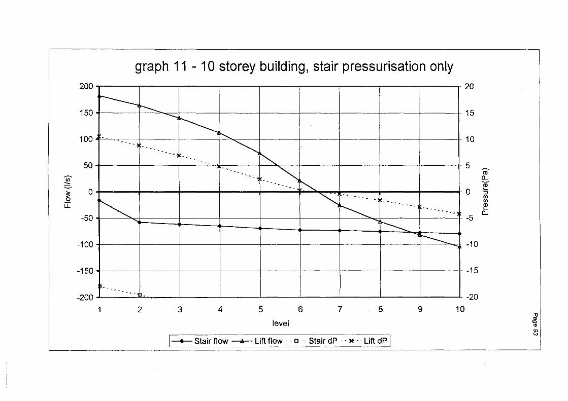
200
150
100
50
-C/) :::::: -~ 0 0
LJ..
-50
-100
-150
-200
graph 11 - 10 storey building, stair pressurisation only
r------., ~
-- - -. --~ ... -.. . -
~ ........
---------~ IL -
1 2
-....... ~ ~
~ - - - ~i-
"" .. --. -.
......... ~ ·---~ ~ . --- ~
3 4 5 6
level
20
15
10
5
~ -------._, --------., ~ ---------)
""""1 ~
0
-5
~ -10
7 . 8 9
"""]
-15
-20
10
\ • Stair flow A Lift flow ·· ·· o ·· ·· Stair dP - · * -:uft(jp ]
-ro 0.... -Q) '-:::J C/) C/) Q) '-
0....
? ~
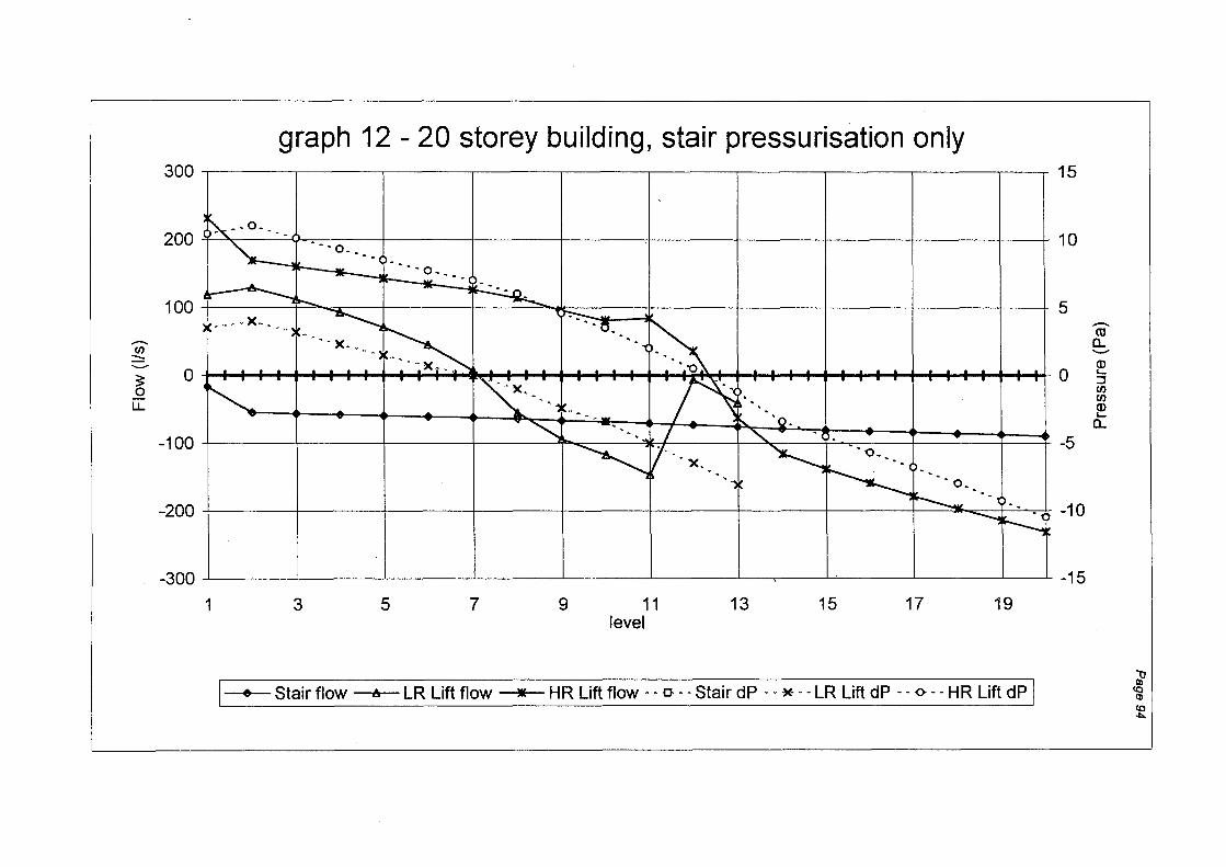
300
200
100
--fJ) ::::: ......... 3 0 0 LL
-100
-200
-300
graph 12 - 20 storey building, stair pressurisation only
-
~--0-. __
- ~ ·--o. __ _ ---- ·-o .. __
- -- ---- ~
......... ... --.,1':-- - --: - i't_ - ~}~ -........._ -- ~~ •... -X •••.. , ~ ••• _.. _.. _.. _.__... •
• --- '-o • • '"··-. ~~ ~-· ;:!' • • ••
....ll.. ....L _._ • - ·u--~ _._ :..a. • ' • ....L....L ....L • • • •
....L • - •
• . . . . ~ .. >--.. ~ ~ 'Q. . .. ~ - -........, . . . L '- -. ""- ... ~~ ·x.... "'-..,1---.... ····o .. __ _
,....-
-- _..._
1 3 5 7 9 11 level
13 15
.....____ - -~ ~N
17 19
I • Stair flow A LR Lift flow • HR Lift flow -- o--- Stair dP -- * ~--~ LR Lift dP -- 0.--=---=---HR Lift dP]
15
10
5
0
-5
-10
-15
--m a.. ......... <D ._ :::J fJ) fJ)
<D ._ a..
l <D co -l:>.
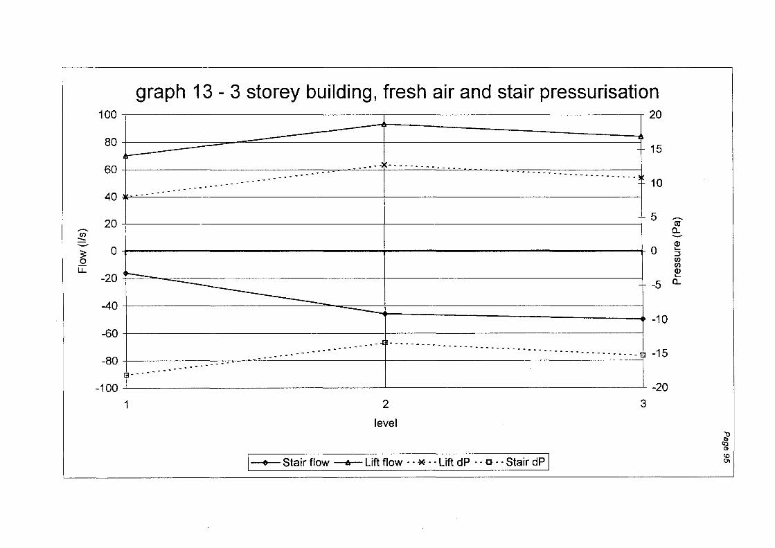
........... f/)
::::: .......... ?; 0
LL
graph 13 - 3 storey building, fresh air and stair pressurisation 100 ~--------------------~------------------~20
80
60 ~ +==========-------==========+==========~ 15 . --- -~----- .. --
... - .......... - -------------------------~ 10 ......... ... ---
40 -.. - ..
20 5 -co a.. ..........
0 +----------------------------------------------~-------------------------------------------+0 (J) ......
-20 t---
::J rn rn (J) ......
-5 a..
-40
-60
-80
-100
--~----------------------------__.-10
.................. --- .. - - - - - - - . - - - - . - - . - - -- - -ljl- - - . - - - - - . - - - - - - . - - - - - - .. - - - - .. - - - - -- . - - - - .. - - - th- -15
--- I ------------------------~
~----------------------------~--------------------------~~0
1 2
level
I • Stair flow t. Lift flow · · * · · Lift dP · · o · ·Stair dP J
3
l (I)
(() 01
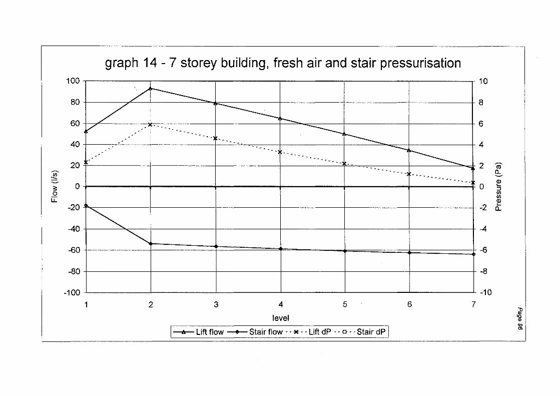
100
80
60
40
20 --.. VJ
::::: -:: 0 0
LL
-20
-40
-60
-80
-100
graph 14 - 7 storey building, fresh air and stair pressurisation 10
/ ~ / ~ r--v '
...... - .... -..... ~ ' 00 ... - " .. I r------_ ' ' . ' ... -.... -...
-. - ............. - .. ----. .
~ . . -. ··········-·----. . .
-- .......... ___ .. __ ..... .....,
8
6
4
2 .... - ........... -- ..... -........
~ ~
1 2 3 4
level
5
I A uliftfto~----. Stair flow --*.-Lift dP -- 0-- Stair dP I
6
0
-2
-4
-6
-8
-10
7
-ro a_ -Q) '-:::J VJ VJ Q) '-a_
';;? ~ <o 0)

150
100
50
.....-.. (/)
::::::: ...........
3: 0 0 lJ..
-50
-100
-150
graph 15 - 10 storey building, fresh air and stair pressurisation
7 r-----J ~r---_
. . --. --., __ ~ --... ~~ .... ~
. ·-. r---__ . -. -. - '
c ··--- -..,~ . -- ~
··----... ~
·--- ... __ l ---------1 ··-··----
10
8
6
4
2
0
J ~ I . I ~ l I I
-2
-4
-6
-8
-10
1 2 3 4 5 6 7 .8 9 10
level
I e Stair flow A Lift flow · - o · · Stair dP ·- * · -l..ittndP I
.....-.. co a.. -Q) ..... ::J (/) (/) Q) ..... a..
~ ~ (() .......

150
100
50
-C/) ::::: .._...
3: 0 0
LL
-50
-100
-150
1
graph 16 - 20 storey building, fresh air and stair pressurisation
3 5 7 9 11 level
13 15 17 19
\ e Stair flow A LR Lift flow • HR Liftflc:>_VI_ ·· ·· .C} ·• ·• StairdP · · ·~ · · LR Lift dP · · <> · · HR Lift dPJ
10
8
6
4
-2 co a.. -<D
0 '-:::J C/) C/)
<D -2 '-a..
-4
-6
-8
-10
~ CQ Q)
(() Q:)
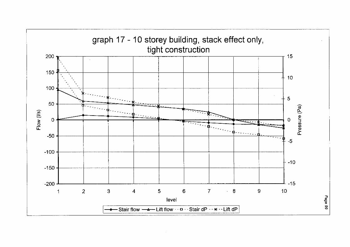
.......... U)
:::::
~ LL
graph 17- 10 storey building, stack effect only, tight construction
200 15
150 -' ' 10
' ' ' '
100 f"-.-.._\ -) _________ " ' 5
I ~ ~ -------~ ---so - ··---·---, --- . ----. ____ r.:---_
--·---- .. , ·-------- ~----~ ~--. 0
I === ---------$ .. __ "-. . -
. 0 .L.--
-50 • - -m ··-- - - · - - -_m-
••... - ftl -5
-100
-10 -150
-200 ~----~------~----~----~------~----~------~----~----~-15
1 2 3 4 5 6 7 . 8 9 10
level
I • Stair flow A Lift flow · · o · --Stair dP - - *--Lift dP I
.......... ro a. ......... Q) '-::J U) U) Q) '-a.
~ !Q
CD (() co

-en ::::: -3 0 u..
graph 18 - 10 storey building, fresh air only, tight construction
150 30
1 DO LeT 1 · ------·t-------·t--------t---------1- --------f. --------~---------! 20
50~ m-. •. ,
,
LL '
0 ..
-----.-.- <jl---. --- .• <Jl-. ---.--- .J.-. · _____ -"ljl·--- ----- ijl----.- --- d!--- ·-----.< 10
0
-50 -10
-100 -20
-150 -30
1 2 3 4 5 6 7 8 9 10
level
I • Stair flow A ~itt flo~o ·· StaifdP --* --Lin dP I
-ro a_ -Q) ,_ ::! en en Q) ,_
a_
;;? CQ <D ...... 0 0

100
80
60
40
20 ......... U)
::::: -~ 0 0 u..
-20
-40
-60
-80
-100
graph 19- 10 storey building, stair pressurisation only, tight construction
r- ----., ~
________ .] lr _ r----..., ......... ---- ...___ . . - . . ~
. • - -'l
J ... -......... - 1------------!
---·-----! ~ "' ...... --.. -- ... t----...... - -...... -
\ \
_\
1 2 3 4 5 6 7 8 9
level
I • Stair flow A Lift flow ·· - ·o ·· ··Stair dP - - * --Lift dP I
20
15
10
5 ......... ro a.. -Q)
0 .._ ::J U) U) Q) .._
- -5 a..
- -10
-15
-20 10
i _.. c _..

...-... (/)
:::::: ..__..
~ LL.
graph 20 - 10 storey building, fresh air+ stair pressurisation, tight construction
200 50
150 - - - - - - - - 40 - - - - - - - - - - - - - - - - - - - - - - - - - - - - - - - - - - - - - - - - - - - - - - - - - - - - - - . - - - - - - - - 30
100 20
50 ...-... 10 g:_
0~ -50
-Q)
0 5 -~' (/) ___ ._ __ -r--- 1 -10 £ ~--~--, i L-4-~ -L-~==r•=4•r=t=~ ...___~, + + -20
-100 ~ ;f--- .... _, . --r--------l-------t--------+------·l-------l--------• -30
-150 ,' -40
~00 ~0
1 2 3 4 5 6 7 8 9 10
level
I • Stair flow A mlift flo; ~.-.. -a.: .:sta-ir~ dP -.*-.Lift d~]
l .... ~

.......... C/)
:::: ..........
3 0
LL.
200
150
100
50
0
-50
-100
-150
graph 21 - 10 storey building, stack only, 29deg ambient
~----~------~----~------~----~------~----~------~----~10
8
6
4
2 -ro :::::::::. e:,
Q)
0 :; .... -··--:::::- :::::::::: _:::::-- ~
·,-- x---- 2 L.. ·.--·T - a_
~ -4
-6·
-8
-200 -10 1 2 3 4 5 6 7 8 9 10
level
I e Stair flow A Lift flow · · ~ -~Stair dP -- ;-:.-=iift dP I l
CD ..... 8

graph 22 - 10 storey building, fresh air, 29deg ambient
150 10
8
100~----~------,_----~------~------~----~------+------+----~ 6
____,
4
~ ••. I
50 ' - " • ' " I'" ' " " " " ' " " .. 2 'i ~
r- Jb - • ~ : • : , •• ~ •• - .......... - - .. J < ' : • , : : c • ~ •• : = •••• : 1!'- (J) .......... ·~ ······---1 0 .._ C/) ::••="=·· ::J
~ C/)
;- 0 ''./ ~ 0 v ~ ~ LL
-50~----~------~------r------r------r------+------+------+----~ -4
-6 -100+------+------+------+------+------r------r------r------~----~
-8
-150 -10 1 2 3 4 5 6 7 8 9 10
level
I e Stair flow A Lift flow ·· ·· o- ··_··stair dP · · * · · Lift dP I
i (I)
~
~

100
80
60
40
.......... 20 rn :::: .__..
3: 0 0
LL -20
-40
-60
-80
-100
graph 23 - 10 storey building, stair pressurisation only, 29deg ambient
-
~
~ ~ -
~ v-- ----------l ----------~
lr---------~ -..... -...... - - .. -........... - ..... - ;....---... -. -~ ----.
~ ~ -
~
v ~ -
/"' -
v 1 2 3 4 5 6 7 8 9 10
level
1
--- -~~~ -~ ------~- -~~ ----~---::Jnl
• Stair flow A Lift flow · ·_o-- ·Stair dP -- '*__-- LiftdP 1
20
15
10
5
0
-5
-10
-15
-20
.......... ro
CL .__.. Q) L-:::J rn rn Q) L-
CL
Jl ~ .... c 01
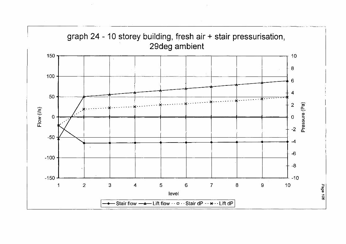
-. en :::::
3: 0 LL
graph 24- 10 storey building, fresh air+ stair pressurisation, 29deg ambient
150T------,------,-------.------r------.-----~------~----~------~
100~----~-------r------r------+------+-----~------,_----~------~
OK -50 ~ "'J • • + + + + ~ +
-100+------1------~------r------+------+-----~------,_----~------~
-150~----~------~------~----~------~----~------~----~-------L
1 2 3 4 5 6 7 8 9 10
level
r e Stair flow A Lift flow .. 0 .. Stair dP - -~-- Lif!_dP I
10
8
6
4
2 -. co
Q_ .......... Q)
0 '-::J en en Q)
-2 '-Q_
-4
-6
-8
-10 \) Ill
(Q Q)
..... 0 0)
FIRE ENGINEERING RESEARCH REPORTS
95/1 Full Residential Scale Backdraft I B Bolliger 95/2 A Study of Full Scale Room Fire Experiments P AEnright 95/3 Design of Load-bearing Light Steel Frame Walls for J T Gerlich
Fire Resistance
95/4 Full Scale Limited Ventilation Fire Experiments D JMillar 95/5 An Analysis of Domestic Sprinkler Systems for Use in FRahmanian
New Zealand
96/1 The Influence of Non-Uniform Electric Fields on MABelsham Combustion Processes
96/2 Mixing in Fire Induced Doorway Flows J M Clements 96/3 Fire Design of Single Storey Industrial Buildings B W Cosgrove 96/4 Modelling Smoke Flow Using Computational Fluid TN Kardos
Dynamics
96/5 Under-Ventilated Compartment Fires- A Precursor to ARParkes Smoke Explosions
96/6 An Investigation of the Effects of Sprinklers on MWRadford Compartment Fires
97/1 Sprinkler Trade Off Clauses in the Approved Documents GJBarnes 97/2 Risk Ranking of Buildings for Life Safety JWBoyes
97/3 Improving the Waking Effectiveness of Fire Alarms in T Grace Residential Areas
97/4 Study of Evacuation Movement through Different Building PHolmberg Components
97/5 Domestic Fire Hazard in New Zealand KDJirwin 97/6 An Appraisal of Existing Room-Corner Fire Models D C Robertson
9717 Fire Resistance of Light Timber Framed Walls and Floors GCThomas 97/8 Uncertainty Analysis of Zone Fire Models AM Walker
97/9 New Zealand Building Regulations Five Years Later T M Pastore 98/1 The Impact of Post-Earthquake Fire on the Built Urban RBotting
Environment
98/2 Full Scale Testing of Fire Suppression Agents on Unshielded MJDunn Fires
98/3 Full Scale Testing of Fire Suppression Agents on Shielded N Gravestock Fires
98/4 Predicting Ignition Time Under Transient Heat Flux Using A Henderson Results from Constant Flux Experiments
98/5 Comparison Studies of Zone and CFD Fire Simulations A Lovatt
98/6 Bench Scale Testing of Light Timber Frame Walls P Olsson
98/7 Exploratory Salt Water Experiments of Balcony Spill Plume EYYii Using Laser Induced Fluorescence Technique
99/1 Fire Safety and Security in Schools RACarter
99/2 A Review of the Building Separation Requirements of the JM Clarke New Zealand Building Code Acceptable Solutions
99/3 Effect of Safety Factors in Timed Human Egress Simulations KMCrawford
99/4 Fire Response of HV AC Systems in Multistorey Buildings: MDixon An Examination of the NZBC Acceptable Solutions
99/5 The Effectiveness of the Domestic Smoke Alarm Signal CDuncan
99/6
9917
99/8
99/9
99/10
99/11
99/12
99/13
99/14
99/15
99/16
Post-flashover Design Fires
An Analysis of Furniture Heat Release Rates by the Nordtest
Design for Escape from Fire
Class A Foam Water Sprinkler Systems
Review of the New Zealand Standard for Concrete Structures (NZS 3101) for High Strength and Lightweight Concrete Exposed to Fire
Simple Empirical Method for Load-Bearing Light Timber Framed Walls at Elevated Temperatures
An Analytical Model for Vertical Flame Spread on Solids: An Initial Investigation
Should Bedroom Doors be Open or Closed While People are Sleeping? - A Probabilistic Risk Assessment
Peoples Awareness of Fire
Smoke Explosions
Reliability of Structural Fire Design
School ofEngineering University of Canterbury
Private Bag 4800, Christchurch, New Zealand
Phone 643 364-2250 Fax 643 364-2758
RFeasey
J Firestone
I J Garrett
DB Hipkins
MJinwood
KHLiew
GANorth
DLPalmer
S J Rusbridge
B J Sutherland
JKSWong