fire protection guide
TRANSCRIPT
7/28/2019 Fire Protection Guide
http://slidepdf.com/reader/full/fire-protection-guide 1/167
DRAFTDG-1094
REGULATORY GUIDE
FIRE PROTECTION FOR OPERATING NUCLEARPOWER PLANTS
Prepared by:Pacific Northwest National Laboratory
Richland, WA 99352
Prepared for:Division of Systems Safety and Analysis
Office of Nuclear Reactor RegulationU.S. Nuclear Regulatory Commission
Washington, DC 20555-0001
NRC Job Code J2415E. A Connell, Technical Monitor
October 1999
.................. ..........

7/28/2019 Fire Protection Guide
http://slidepdf.com/reader/full/fire-protection-guide 2/167
Table of Contents
A. PURPOSE........., . .,o......... .... ................... .. ................ 10
B. DISCUSSION ....................................................... 11
1. BACKGROUND: History of Nuclear Power Plant Fire Protection ........ 11
2. REGULATORY REQUIREMENTS ................................. 15
2.1 10 CFR Part 50, Appendix A, General Design Criteria for Nuclear Power
Plants ......................... ........................ 15
2.1.1 General Design Criterion 3. Fire Protection ...................... 15
2.1.2 General Design Criterion 5, Sharing of Structures, Systems, and
Components ............................................. 16
2.1.3 General Design Criterion 23, Protection System Failure Modes ....... 16
2.2 10 CFR Part 50.48 ........................................ 16
2.3 10 CFR Part 50, Appendix R ................................ 172.4 10 CFR Part 50.59 Changes, tests and experiments ................ 17
2.5 10 CFR Parts 50.72 and 50.73 ............................... 18
3. LICENSING AND DESIGN BASIS ................................ 18
3.1 Plants Licensed Prior to January 1, 1979 ........................ 18
3.1.1 Safety Evaluation Reports ................................... 19
3.1.2 Exemptions to Appendix R .................................. 19
3.1.3 Operating License Conditions ................................ 20
3.2 Plants Licensed After January 1, 1979 .......................... 20
4. FIRE PROTECTION PROGRAM GOALS / OBJECTIVES .............. 21
4.1 Defense-in-Depth ......................................... 21
4.2 Assumptions ............................................. 214.2.1 Postulated Fire ........................................ 21
4.2.2 Conditions of Fire Occurrence ................................ 22
4.2.3 Loss of Offsite Power/Station Blackout ........................ 22
4.2.4 Fragility of Structures, Systems, and Components to Fire Damage .... 23
4.3 Fire Protection Program Performance Goals .................. 23
4.3.1 Safety-Related Structures,. Systems, and Components .............. 23
4.3.2 Post-Fire Safe Shutdown .................................... 23
4.3.3 Prevention of Radiological Release ............................ 23
4.4 Post-Fire Safe Shutdown Reactor Safety / Performance Goals ........ 24
4.4.1 Power Operations ......................................... 244.4.2 Shutdown/Refueling Operation .............................. 24
C. REGULATORY POSITION .... ... ............................... 25
1. GENERAL PROGRAM/PLAN REQUIREMENTS ........................ 25
1.1 Fire Protection Program .................................... 25
1.1.1 Organization, Staffing, and Responsibilities ...................... 26
1.1.1.1 Offsite Positions/Organizations ................... 26
1.1.1.2 Onsite Positions/Organizations .................... 26
1.1.2 Fire Hazards Analysis ...................................... 28

7/28/2019 Fire Protection Guide
http://slidepdf.com/reader/full/fire-protection-guide 3/167
1.1.3 Safe Shutdown Analysis .................................... 29
1.1.4 Fire Test Reports and Fire Data ................... 29
1.1.5 Compensatory Measures .................................... 30
1.2 Fire Protection Training and Oualifications ...................... 311.2.1 Fire Protection Staff Training and Qualifications .................. 31
1.2.2 General Employee Training .................................. 31
1.2.3 Fire Watch Training ....................................... 32
1.2.4 Fire Brigade Training and Qualifications ........................ 32
1.2.4.1 Oualifications ................................. 32
1.2.4.2 Instruction ................................... 33
1.2.4.3 Fire Brigade Practice ........................... 34
1.2.4.4 Fire Brigade Training Records .................... 34
1.3 Quality Assurance ......................................... 35
1.4 Fire Protection Program Changes/Code Deviations ................ 35
1.4.1 50.59 Evaluations ....................................... 351.4.2 Exemptions to Appendix R of 10 CFR Part 50 ................... 35
1.4.3 Appendix R Equivalency Evaluations .......................... 37
1.4.4 Deviations ............................................... 37
1.4.5 Operability Assessments .................................... 37
1.4.6 50.72 and 50.73 Reporting .................................. 37
1.4.7 NFPA Code and Standard Deviation Evaluations ................. 38
2. FIRE PREVENTION ............................................. 38
2.1 Control of Combustibles .................................... 39
2.1.1 Transient Fire Hazards ..................................... 39
2.1.2 In situ Fire Hazards ........................................ 40
2.1.3 Flammable and Combustible Liquids and Gases ................... 402.1.4 External/Exposure Fire Hazards .............................. 41
2.2 Control of Ignition Sources ............................... 41
2.2.1 Open Flame, Welding, Cutting and Grinding (Hot Work) ........... 41
2.2.2 Temporary Electrical Installations ............................. 43
2.2.3 Other Sources ............................................ 43
2.3 Housekeeping ............................................ 43
2.4 Fire Protection System Maintenance and Impairments .............. 44
3. FIRE DETECTION AND SUPPRESSION ........................... 44
3.1 Fire Detection (Design Objectives and Performance Criteria) ........ 44
3.1.1 Fire Detection and Alarm Design Objectives and Performance Criteria
............
................ .... ................. .. 443.2 Fire Protection Water Supply Systems (Design Objectives and
Performance Criteria) ................................. 46
3.2.1 Fire Protection Water Supply ................................ 46
3.2.2 Fire Pumps .............................................. 48
3.2.3 Fire Mains ........................................... 48
3.3 Automatic Suppression Systems (Design Objectives and Performance
C riteria) ................................................ 50
3.3.1 Water-based Systems ...................................... 50
3.3.1.1 Sprinkler and Spray Systems ..................... 50
7/28/2019 Fire Protection Guide
http://slidepdf.com/reader/full/fire-protection-guide 4/167
3.3.1.2 Water Mist Systems ............................ 50
3.3.1.3 Foam-Water Sprinkler and Spray Systems ........... 50
3.3.2 Non-Water Based Systems ................................... 50
3.3.2.1 Carbon Dioxide (COo) Systems ................... 51
3.3.2.2 Halon ....................................... 51
3.3.2.3 Clean Agents ................................ 523.4 Manual Suppression Systems and Eguipment .................... 53
3.4.1 Standpipes and Hose Stations ................................ 53
3.4.2 Hydrants and Hose Houses .................................. 53
3.4.3 Manual Foam ............................................ 54
3.4.4 Fire Extinguishers ...................................... 54
3.5 Manual Fire Fighting Capabilities ............................. 54
3.5.1 Fire Brigade ............................................. 54
3.5.1.1 Fire Brigade Staffing ........................... 54
3.5.1.2 Equipment ................................... 55
3.5.1.3 Procedures and Prefire Plans ..................... 55
3.5.1.4 Performance Assessment/Drill Criteria ............. 573.5.2 Offsite Manual Fire-Fighting Resources ........................ 58
3.5.2.1 Capabilities .................................. 58
3.5.2.2 Training ..................................... 59
3.5.2.3 Agreement/Plant Exercise ....................... 59
4. BUILDING DESIGN/PASSIVE FEATURES .......................... 59
4.1 General Building and Building System Design. ................... 60
4.1.1 Combustibility of Building Components and Features .............. 61
4.1.1.1 Interior Finish ................................ 61
4.1.1.2 Testing and Qualification ........................ 61
4.1.2 Compartmentation, Fire Areas and Zones ....................... 62
4.1.2.1 Fire Areas ................................... 624.1.2.2 Fire Zones ................................... 63
4.1.2.3 Access and Egress Design ....................... 64
4.1.3 Electrical Cable System Fire Protection Design ................... 65
4.1.3.1 Cable Design ................................. 65
4.1.3.2 Raceway/Cable Tray Construction ................. 65
4.1.3.3 Electrical Cable System Fire Detection and Suppression
....- ••..-.. .................................. 65
4.1.3.4 Electrical Cable Separation ....................... 66
4.1.3.5 Transformers ................................. 67
4.1.3.6 Electrical Cabinets ............................. 67
4.1.4 HVAC Design ............................................ 674.1.4.1 Combustibility of Filter Media .................... 68
4.1.4.2 Smoke Control/Removal ........................ 68
4.1.4.3 Habitability .................................. 69
4.1.4.4 Fire/Smoke Dampers ........................... 69
4.1.5 Drainage ................................................ 70
4.1.6 Emergency Lighting ....................................... 70
4.1.6.1 Life Safety ................................... 70
4.1.6.2 Post-Fire Safe Shutdown ........................ 70
4.1.7 Communications .......................................... 71
7/28/2019 Fire Protection Guide
http://slidepdf.com/reader/full/fire-protection-guide 5/167
4.1.8 Explosion Prevention ........................... ........... 72
4.2 Passive Fire Resistive Features ............................... 73
4.2.1 Structural Fire Barriers ..................................... 73
4.2.1.1 Wall, Floor, and Ceiling Assemblies ................ 74
4.2.1.2 Fire Doors ................................... 74
4.2.1.3 Fire Dampers ................................. 754.2.1.4 Penetration Seals .............................. 76
4.2.1.5 Testing and Qualification ......................... 76
4.2.1.6 Evaluation of Penetration Seal Designs with Limited
Testing ........ ..................................... 78
4.2.2 Structural Steel Protection ................................... 79
4.2.3 Fire Resistive Protection for Electrical Circuits ................... 80
4.2.3.1 Electrical Raceway Fire Barrier Systems ............ 80
4.2.3.2 Fire Rated Cables .......... .................. 80
4.2.3.3 Fire Stops for Vertical Cable Routing ............... 80
4.2.3.4 Testing and Oualification ........................ 80
5. SAFE SHUTDOWN CAPABILITY ................................. 815.1 Safe Shutdown Performance Goals ............................ 82
5.2 Reactor Performance Criteria ................................ 82
5.3 Hot Standby (PWR) Hot Shutdown (BWR) Systems and Instrumentation
. ..... .......•. • ................ ... ........... ...... 83
5.3.1 PWR Systems and Instrumentation ........................... 84
5.3.1.1 Reactivity Control............................. 84
5.3.1.2 Reactor Coolant Makeup ........................ 84
5.3.1.3 Reactor Coolant System Pressure Control ........... 84
5.3.1.4 Decay Heat Removal ........ 84
5.3.1.5 Process Monitoring Instrumentation ................ 845.3.1.6 Support ..................................... 85
5.3.2 BWR Systems and Instrumentation ........................... 85
5.3.2.1 Reactivity Control .................................. 85
5.3.2.2 Reactor Coolant Makeup ....................... 85
5.3.2.3 Reactor Pressure Control and Decay Heat Removal .... 85
5.3.2.4 Suppression Pool Cooling ...................... 85
5.3.2.5 Process Monitorin ............................ 85
5.3.2.6 Support ..................................... 86
5.4 Cold Shutdown Systems and Instrumentation and
Allowable Repairs ......................................... 865.4.1 PWR Systems and Instrumentation ............................ 87
5.4.1.1 Reactor Cooling System Pressure Reduction to Residual
Heat Removal System (RHR) Capability ............ 87
5.4.1.2 Decay Heat Removal ........................... 87
5.4.1.3 Support ..................................... 87
5.4.2 BWVR Systems and Instrumentation ............................ 87
5.4.2.1 Decay Heat Removal ........................... 87
5.4.2.2 Support ..................................... 87
5.5 Fire Protection of Safe Shutdown Capability ..................... 87
7/28/2019 Fire Protection Guide
http://slidepdf.com/reader/full/fire-protection-guide 6/167
5.6 Alternative or Dedicated Shutdown Capability ................... 88
5.6.1 General Guidelines ........................................ 88
5.6.2 Control Room Fires ....................................... 89
5.7 Post-Fire Safe Shutdown Procedures .......................... 90
5.7.1 Safe Shutdown Procedures .................................. 90
5.7.2 Alternative Shutdown Procedures ............................. 915.7.3 Repair Procedures ......................................... 91
6. FIRE PROTECTION FOR AREAS IMPORTANT TO SAFETY .......... 91
6.1 Areas Related to Power Operation ............................ 92
6.1.1 Containment .......................................... 92
6.1.1.1 Containment Electrical Separation ................. 92
6.1.1.2 Containment Fire Suppression .................... 93
6.1.1.3 Containment Fire Detection ...................... 93
6.1.2 Control Room Complex .................................. 94
6.1.2.1 Control Room Fire Suppression ................... 94
6.1.2.2 Control Room Fire Detection ..................... 95
6.1.2.3 Control Room Ventilation ....................... 956.1.3 Cable Spreading Room ..................................... 95
6.1.4 Plant Computer Rooms ..................................... 96
6.1.5 Switchgear Rooms ........................................ 97
6.1.6 Remote Panels ........................................... 97
6.1.7 Station Battery Rooms ..................................... 98
6.1.8 Diesel Generator Rooms .................................... 98
6.1.9 Pump Rooms ............................................ 99
6.2 Other Areas ............................................ 100
6.2.1 New Fuel Areas ......................................... 100
6.2.3 Radwaste Building/Storage Areas and Decontamination Areas ...... 100
6.2.4 Dry Cask Spent Fuel Storage Areas .......................... 1016.2.5 Water Tanks ............................................ 101
6.2.6 Cooling Towers ......................................... 101
7. PROTECTION OF SPECIAL FIRE HAZARDS EXPOSING AREAS
IMPORTANT TO SAFETY ..................................... 101
7.1 Areas of High Cable Concentration ........................... 101
7.2 RCP Oil Collection ....................................... 102
7.3 Turbine / Generator Building ................................ 103
7.3.1 Oil Systems ............................................. 103
7.3.3 Hydrogen System ........................................ 103
7.3.5 Smoke Control .......................................... 103
7.4 Station Transformers...................................... 1037.5 Diesel Fuel Oil Storage Areas ............................... 104
7.6 Flammable Gas Storage and Distribution ....................... 104
D. IMPLEMENTATION ................................................ 106
REFERENCES ............................................................ 107
GLOSSARY ............................................................. 111
..........................
7/28/2019 Fire Protection Guide
http://slidepdf.com/reader/full/fire-protection-guide 7/167
APPENDIX A: FIRE HAZARDS ANALYSIS .................................. 116
APPENDIX B: SAFE SHUTDOWN ANALYSIS ................ 119
APPENDIX C: 10 CFR 50.59 SAFETY EVALUATIONS .......................... 124
APPENDIX D: EXEMPTIONS TO APPENDIX R TO PART 50 .................... 130
APPENDIX E: OPERABILITY ASSESSMENTS ................................ 131
APPENDIX F: 50.72 AND 50.73 REPORTING .................................. 132
APPENDIX G: FIRE PROTECTION QUALITY ASSURANCE GUIDELINES ......... 133
APPENDIX H: ELECTRICAL RACEWAY FIRE BARRIER TESTING .............. 142
APPENDIX I: EQUIVALENCY ............................................. 151
APPENDIX J: GUIDANCE SOURCE CITATIONS ............................... 153
..... .........
7/28/2019 Fire Protection Guide
http://slidepdf.com/reader/full/fire-protection-guide 8/167
DRAFT
REGULATORY GUIDE
FIRE PROTECTION FOR OPERATING NUCLEAR
POWER PLANTS
A. PURPOSE
Fire protection programs at U.S. nuclear plants have the primary objective of minimizing both
the probability of occurrence and consequences of fire. To meet these objectives, the fire
protection programs for operating nuclear power plants are designed to provide reasonable
assurance, through defense-in-depth, that a fire will not prevent the performance of necessary
safe shutdown functions and will not significantly increase the risk of radioactive releases to the
environment.
The Commission's requirements for nuclear plant fire protection programs are promulgated in a
number of regulations and supporting guidelines, including, but not limited to, General Design
Criterion (GDC) 3, 10 CFR 50.48, 10 CFR 50 Appendix R, generic communications (e.g.,
Generic Letters, Bulletins, and Information Notices), NUREG reports, the Standard Review Plan
(NUREG-0800) and associated Branch Technical Positions, and industry standards.
Section B of this guide provides a brief history and discussion of development and application of
fire protection regulations and guidelines in the U.S. commercial nuclear power industry. The
discussion includes summaries of the applicable regulations, the primary fire protection
objectives, the varied licensing and design bases, and the primary assumptions relative to
postulated fire events for nuclear power reactors.
Section C provides staff positions and guidance relative to providing an acceptable level of fire
protection for operating nuclear power plants. The positions and guidance provided are a
compilation of the fire protection requirements and guidelines from the existing regulations and
staff guidance. In addition, as appropriate new guidance is provided where the existing guidance
is weak or non-existent. Appendices to the guide that are referenced in Section C provide
additional guidance on select topics.
Section D provides a brief description of the intended implementation, application, and use of
this guide relative to existing fire protection programs.
This regulatory guide was developed to provide a comprehensive fire protection guidance
document, and to identify the scope and depth of fire protection that the staff has determined to
be acceptable for operating nuclear plants. This guide may be used for licensee self-assessments
and as the deterministic basis for future rulemaking.
10
7/28/2019 Fire Protection Guide
http://slidepdf.com/reader/full/fire-protection-guide 9/167

7/28/2019 Fire Protection Guide
http://slidepdf.com/reader/full/fire-protection-guide 10/167
should develop detailed guidance for implementing the general design criterion for fire
protection; and (2) should conduct a detailed review of the fire protection program at each
operating nuclear power plant, comparing it to the guidance developed.
In May 1976, the NRC issued BTP APCSB 9.5-1 which incorporated the
recommendations from the Browns Ferry fire special review team, and provided technicalguidelines to assist licensees in preparing their fire protection programs. As part of this
action, the staff requested each licensee to provide an analysis that divided the plant into
distinct fire areas and demonstrated that redundant divisions of equipment required to
achieve and maintain safe shutdown conditions for the reactor were adequately protected
from fire damage. However, the guidelines of BTP APCSB 9.5-1 applied only to those
licensees that filed for a construction permit after July 1, 1976.
In September 1976, in an effort to establish defense-in-depth fire protection programs,
without significantly affecting the design, construction, or operation of existing plants
that were either already operating or well past the design stage and into construction, the
NRC modified the guidelines in BTP APCSB 9.5-1, and issued Appendix A to BTPAPCSB 9.5-1. This guidance provided acceptable alternatives in areas where strict
compliance with BTP APCSB 9.5-1 would require significant modifications.
Additionally, the NRC informed each plant that the guidance in Appendix A would be
used to analyze the consequences of a postulated fire within each area of the plant, and
requested licensees to provide results of the fire hazards analysis performed for each unit
and the technical specifications for the present fire protection systems.
Early in 1977 each licensee responded with a fire protection program evaluation which
included a fire hazard analysis. These analyses were reviewed by the staff using the
guidelines of Appendix A to BTP APCSB 9.5-1. The staff also conducted inspections of
operating reactors to examine the relationship of structures, systems, and componentsimportant to safety with the fire hazards, potential consequences of fires, and the fire
protection features. After reviewing licensee responses to the BTP, the staff determined
that additional guidance on the management and administration of fire protection
programs was necessary, and in mid-1977, issued Generic Letter 77-002, which provided
criteria used by the staff in review of specific elements of a licensee's fire protection
program, including organization, training, combustible and ignition source controls, fire
fighting procedures and quality assurance. Many fire protection issues were resolved
during the BTP review process, and agreements were included in the NRC-issued safety
evaluation reports (SERs).
By the late 1970s to early 1980, the majority of operating plants had completed theiranalyses and implemented most of the fire protection program guidance and
recommendations specified in Appendix A to the BTP. In most cases, the NRC had
found the licensee's proposed modifications resulting from these analyses to be
acceptable. In certain instances, however, technical disagreements between licensees and
the NRC staff led to some licensee's opposition to adopt some of the specified fire
protection recommendations, such as the requirements for fire brigade size and training,
water supplies for fire suppression systems, alternate and dedicated shutdown capability,
12
....... . ...........

7/28/2019 Fire Protection Guide
http://slidepdf.com/reader/full/fire-protection-guide 11/167
emergency lighting, qualifications of penetration seals used to enclose places where
cables penetrated fire barriers, and the prevention of reactor coolant pump oil system
fires. Following deliberation, the Commission determined that, given the generic nature
of some of the disputed issues, a rulemaking was necessary to ensure properimplementation of NRC fire protection requirements.
In November 1980, the NRC published the "Fire Protection" rule, 10 CFR 50.48, which
specified broad performance requirements, as well as Appendix R to 10 CFR Part 50,
"Fire Protection Program for Nuclear Power Facilities Operating Prior to January 1,1979" which specified detailed regulatory requirements for resolving the disputed issues.
As originally proposed (Federal Register Vol. 45, No. 1&5, May 22, 1980), Appendix Rwould have applied to all plants licensed prior to January 1, 1979 including those for
which the staff had previously accepted the fire protection features as meeting the
provisions of Appendix A to BTP APCSB 9.5-1. After analyzing comments on theproposed rule, the Commission determined that only three of the fifteen items in
Appendix R were of such safety significance that they should apply to all plants (licensedprior to January 1, 1979), including those for which alternative fire protection actions had
been approved previously by the staff. These items are fire protection of safe shutdown
capability (including alternate shutdown systems), emergency lighting, and the reactorcoolant pump oil system. Accordingly, the final rule required all reactors licensed to
operate before January 1, 1979, to comply with these three items even if the NRC hadpreviously approved alternative fire protection features in these areas (Federal RegisterVol. 45, Nov. 19, 1980). In addition, the rule provided an exemption process that can berequested by a licensee provided that a required fire protection feature to be exempted
would not enhance fire protection safety in the facility or that such modifications may be
detrimental to overall safety (10 CFR 50.48(c)(6)). Under this process, if the Director,
Nuclear Reactor Regulation determined that a licensee has made a prima facie showingof a sound technical basis for such an assertion, then the implementation dates of the rulewere tolled until final Commission action on the exemption request. 10 CFR 50.48 andAppendix R to 10 CFR Part 50 became effective on February 17, 1981.
During the initial backfit of the fire protection regulation, the NRC approved a large
number of plant-specific exemptions (i.e., alternative methods to achieve the underlying
purpose of the regulation) at about 60 nuclear power plants. Since the mid- 1980s, as
licensee's programs became more compliant with the fire protection regulations, the
number of exemptions requested and approved has decreased. Even so, the ongoing
review of licensee fire protection programs, the licensee efforts to save costs while
maintaining an acceptable level of safety, and the emergence of additional technicalissues (such as the deliberations over the adequacy of Thermo-Lag as a fire protection
barrier) have resulted in several hundred exemptions to specific elements of the NRC fire
protection requirements. This progression, the broad provisions of the general design
criterion, the detailed implementing guidance, the plant-by-plant review, and finally the
issuance and backfit of the fire protection regulation and the prescriptive requirements of
Appendix R, resulted in a complex regulatory framework for fire protection in U.S.
nuclear power plants licensed prior to 1979, and resulted in the issuance of a number of
13

7/28/2019 Fire Protection Guide
http://slidepdf.com/reader/full/fire-protection-guide 12/167
additional guidelines, clarifications, and interpretations, primarily as generic letters.
Plants licensed after January 1, 1979, were not required to meet the provisions of
Appendix R unless specified in specific license conditions. These plants were typically
reviewed to the guidelines of Section 9.5-1 of the Standard Review Plan (NUREG-0800),
which subsumed the criteria specified in Appendix R.
Following promulgation of 10 CFR 50.48 and Appendix R, the staff issued Generic
Letter 81-12 (February 20, 1981) and later its associated clarification letter (March 22,
1982). In these letters, the staff identified the information necessary to perform their
reviews of licensee compliance with the alternate shutdown requirements of Section II.G
of Appendix R. Staff guidance provided in these letters defined safe shutdown
objectives, reactor performance goals, necessary safe shutdown systems and components,
and associated circuit identification and analysis methods. Generic Letter 81-12 also
requested that technical specifications be developed for safe shutdown equipment that
was not already included in the existing plant technical specifications.
Most licensees requested and were granted additional time to perform their reanalysis,propose modifications to improve post fire safe shutdown capability and to identify
exemptions for certain fire protection configurations. In reviewing some exemption
requests, the staff noted that a number of licensees had made significantly different
interpretations of certain requirements. These differences were identified in the staff's
draft SERs, and were discussed on several occasions with the cognizant licensees. These
discussions culminated in the issuance of Generic Letter 83-33 (October 19, 1983).
Certain licensees disagreed with. or found it difficult to implement, the interpretations
provided in Generic Letter 83-33. To pursue the matter with senior NRC management,
the industry formed the Nuclear Utility Fire Protection Group. Subsequently, the staff
formed the Steering Committee on Fire Protection Policy.
Following staff inspections ol operating plants, which identified a number of significant
items of non-compliance, and dLsagreements in the implementation of interpretations
provided in Generic Letter S3-33. the Nuclear Utility Fire Protection Group requested
interpretations of certain Appendix R requirements and provided a list of questions to be
discussed with the industry. The NRC responded by holding workshops in each Region
to assist the industry in understanding the NRC's requirements and to improve the staff s
understanding of the industr"s concerns. The results of these workshops and the
Steering Committee's findings and recommendations for addressing ongoing fire
protection issues were documented in Generic Letter 85-01. Generic Letter 85-01
included a proposed Generic Letter that provided additional interpretations related tocompliance with Appendix R and staff answers to the industry's list of questions from the
workshops. This proposed Generic Letter was revised and later issued as Generic Letter
86-10, "Implementation of Fire Protection Requirements" on April 24, 1986.
Also included in Generic Letter 86-10, was a "standard license condition" for adoption by
licensees. Through the implementation and adoption of a standard license condition, a
licensee was allowed to make changes to its fire protection program without prior
14
.........• i• • m•• ............ • I

7/28/2019 Fire Protection Guide
http://slidepdf.com/reader/full/fire-protection-guide 13/167
notification of the NRC in accordance with the provisions of 10 CFR 50.59, provided the
changes did not adversely affect the reactor plant's ability to achieve and maintain a post
fire safe shutdown. The licensee, upon modification of the license to adopt the standard
condition, could also amend the license to remove the fire protection technical
specifications. Generic Letter 88-12, Removal of fire Protection Requirements from
Technical Specifications" (August 2, 1988) gave licensees additional guidance forimplementation of the standard license condition and removal of the technical
specifications associated with fire detection and suppression, fire barriers, and fire
brigade staffing. The technical specifications associated with safe shutdown equipment
and the administrative controls related to fire protection audits were to be retained under
the guidance of the generic letter.
As illustrated in the preceding discussion, the Commission's fire protection requirements
and guidelines consist of a multitude of rules, generic communications, staff guidance,
and other related documents. Current industry and regulatory issues have prompted
action on the part of the NRC to compile the current fire protection regulations and
guidelines for operating reactors into this comprehensive guide.
2. REGULATORY REQUIREMENTS
There are a number of regulatory requirements with applicability to the development and
implementation of fire protection programs for operating nuclear power plants. The
primary requirements are summarized in this section.
2.1 10 CFR Part 50, Appendix A, General Design Criteria for Nuclear Power Plants
Appendix A to 10 CFR 50, establishes the necessary design, fabrication, construction,
testing, and performance requirements for structures, systems, and components importantto safety. The following subsections summarize those GDC with specific application to
fire protection of nuclear power plants.
2.1.1 General Design Criterion 3, Fire Protection
GDC 3 requires that structures, systems, and components important to safety be designed
and located to minimize, consistent with other safety requirements, the probability and
effect of fires and explosions. Noncombustible and heat resistant materials are required to
be used wherever practical, particularly in locations such as the containment and control
room. Fire detection and fighting systems of appropriate capacity and capability are
required to be provided and designed to minimize the adverse effects of fires onstructures, systems, and components important to safety. GDC 3 also requires that
firefighting systems be designed to ensure that their failure, rupture or inadvertent
operation does not significantly impair the safety capability of these structures, systems,
and components.
15

7/28/2019 Fire Protection Guide
http://slidepdf.com/reader/full/fire-protection-guide 14/167
2.1.2 General Design Criterion 5, Sharing of Structures, Systems, and Components
GDC 5 requires that structures, systems, and components important to safety not be
shared among nuclear power units unless it can be shown that such sharing will not
significantly impair their ability to perform their safety functions, including, in the event
of an accident in one unit, an orderly shutdown and cooldown of the remaining units.
2.1.3 General Design Criterion 19, Control Room
GDC 19 requires that a control room be provided from which actions can be taken to
operate the nuclear power unit under normal and accident conditions, while limiting
radiation exposure to control room personnel under accident conditions for the duration
of the accident. GDC 19 also requires that equipment and locations outside the control
room be provided that with the design capability to accomplish safe shutdown of the
reactor.
2.1.3 General Design Criterion 23, Protection System Failure Modes
GDC 23 requires that the protection system be designed to fail into a safe state or into a
state demonstrated to be acceptable on some other defined basis if conditions such as
disconnection of the system, loss of energy (e.g., electric power, instrument air), or
postulated adverse environments (e.g., extreme heat or cold, fire, pressure, steam, water,
and radiation) are experienced.
2.2 10 CFR Part 50.48
Section 50.48 of 10 CFR Part 50 requires that each operating nuclear power plant have a
fire protection plan that satisfies General Design Criterion 3 of Appendix A to10 CFR 50. It specifies what should be contained in such a plan and lists the basic fire
protection guidelines for the plan.
Section 50.48 also requires that all plants with operating licenses prior to January 1, 1979
satisfy the requirements of Section HI.G, III.J and H1.O, and other sections of 10 CFR 50,
Appendix R where approval of similar features had not been obtained prior to the
effective date of Appendix R. The rule also established schedules for completion of
modifications necessary to comply with the staff's requirements, an exemption process
for those areas where compliance could not be achieved, and specified the basic
requirements for plants licensed after January 1, 1979.
Plants licensed to operate after January 1, 1979, must meet the provisions of 10 CFR
50.48 paragraphs (a) and (e).
As discussed later in Section B.3 of this guide, deviations from NRC fire protection
requirements are documented and reviewed under different processes depending on the
date of the operating license. Appendix R requirements for pre-1979 plants are processed
under the exemption process. Deviations from other applicable guidelines are identified
16

7/28/2019 Fire Protection Guide
http://slidepdf.com/reader/full/fire-protection-guide 15/167
and evaluated in the staff's Safety Evaluation Reports. For post-1979 plants, where fireprotection features do not meet applicable NRC requirements or commitments, or
alternative approaches are proposed, the condition is documented as a deviation.
2.3 10 CFR Part 50, Appendix R
Appendix R to 10 CFR Part 50 applies to licensed nuclear power electric generatingstations that were operating prior to January 1, 1979, except as noted in 10 CFR 50.48(b).With respect to certain generic issues for such facilities, Appendix R identifies fire
protection features required to satisfy Criterion 3 of Appendix A. There are two
categories of Appendix R provisions that are applicable to the fire protection features of
these facilities.
The first category consists of those provisions that were required to be backfit in their
entirety, regardless of whether alternatives to the specific requirements had beenpreviously approved by the NRC. The requirements are identified in Sections III.G, Fire
Protection of Safe Shutdown Capability; Hll.J, Emergency Lighting; and 111.0, OilCollection System for Reactor Coolant Pump. Those plants subject to the requirementsof Section III.G.3, must also meet the requirements of Section lII.L. These specificrequirements were required to be satisfied by the dates identified in 10 CFR 50.48(c).
The second category consists of requirements concerning the open items of previousNRC staff fire protection reviews. Open items are defined as fire protection features thathad not been previously approved by the NRC staff as satisfying the provisions of
Appendix A to BTP APCSB 9.5-1, as reflected in SERs. Facility fire protection features
in this category were also required to satisfy the specific requirements of Appendix R bythe dates identified in 10 CFR 50.48(c), unless an exemption was approved by the
Commission.
Except as specified in the 1wen-se conditions of individual plants, Appendix R was notrequired to be implemented bh.plants that were licensed to operate after January 1, 1979.
Rather, fire protection programs at these later plants were typically reviewed against thelicensing review guidelines ot Section 9.5-1 to the Standard Review Plan (NUREG
0800). SRP Section 9.5-1 and the associated BTP CMEB 9.5-1, consolidated theguidance of the previous BTP. Appendix A to BTP APCSB 9.5-1, Appendix R and other
staff guidance.
2.4 10 CFR Part 50.59 Changes. tests and experiments
10 CFR 50.59 allows holders of a license authorizing operation of production or
utilization facilities to make changes in the facility or the procedures described in the
safety analysis report (including the fire protection program), and conduct tests orexperiments not described in the safety analysis report, without prior Commission
approval, unless the proposed change, test or experiment involves a change in the
technical specifications incorporated in the license or an unreviewed safety question. Thelicensee is required to maintain records of changes in the facility, changes in procedures,
17

7/28/2019 Fire Protection Guide
http://slidepdf.com/reader/full/fire-protection-guide 16/167
and of tests and experiments. The records should include a written safety evaluation
which provides the bases for the determination that the change, test, or experiment does
not involve an unreviewed safety question.
Licensees are required to submit an annual report containing a brief description of any
changes, tests, and experiments, including a summary of the safety evaluation of each.Guidance on performance of fire protection related 50.59 evaluations is provided in
Appendix C.
2.5 10 CFR Parts 50.72 and 50.73
These regulations prescribe the reporting requirements for nuclear power plant licensees,
including those related to fire protection programs. Section 50.72 provides for immediate
notification requirements via the emergency notification system (ENS), and Section
50.73 provides for 30-day written licensee event reports (LERs).
The information reported under 10 CFR 50.72 and 50.73 is used by the NRC staff inresponding to emergencies, monitoring ongoing events, confirming licensing bases,
studying potentially generic safety problems, assessing trends and patterns of operational
experience, monitoring performance, identifying precursors of more significant events,and providing operational experience to the industry. Guidelines for the application of
these requirements are provided in NUREG-1022, "Event Reporting Guidelines: 10 CFR
50.72 and 50.73."
3. LICENSING AND DESIGN BASIS
The fire protection licensing and design basis is dependent on a number of factors that
may differ considerably for individual plants. However, with the issuance of the fireprotection rule, 10 CFR 50.48, and 10 CFR 50, Appendix R, the applicability of certain
fire protection requirements, including those within the rule, was established on the basis
of the licensing date for a given plant being before, or after, January 1, 1979.
3.1 Plants Licensed Prior to January 1. 1979
The primary licensing basis for plants licensed to operate prior to January 1, 1979, is
comprised of the plant license condition(s), Appendix R and any approved exemptions,
and the staff's Safety Evaluation Reports (SERs) on the fire protection program.
3.1.1 Safety Evaluation Reports
The SERs document the staff acceptance of the plant fire protection program, or elements
thereof. For those plants licensed to operate prior to January 1, 1979, the staff's SERs
also establish the extent to which the requirements of 10 CFR 50, Appendix R apply.
Plants whose fire protection features were accepted by the NRC as satisfying the
provisions of Appendix A to Branch Technical Position (BTP) APCSB 9.5-1, or were
accepted in comprehensive SERs issued prior to publication of Appendix A to BTP
18
7/28/2019 Fire Protection Guide
http://slidepdf.com/reader/full/fire-protection-guide 17/167
APCSB 9.5-1 in August 1976, were only required to meet the provisions of Sections
IIL.G (1H.L) , 11I.J, and 111.0 of Appendix R.
3.1.2 Exemptions to Appendix R
Effective February 17, 1981, the NRC amended its regulations by adding Part 50.48 and10 CFR 50, Appendix R, requiring certain provisions for fire protection in nuclear power
plants licensed to operate before January 1, 1979.
Plants with previously approved fire protection features (See Section B.3.1.1 above) were
exempted from the requirements of Appendix R with the exception of Sections III.G,
HLI.J, and 1l.O.
10 CFR 50.48(c) established the schedule requirements for licensees to comply with the
provisions of Appendix R. Provisions were also included in the rule to allow licensees to
file exemptions from Appendix R requirement(s) on the basis that the required
modifications would not enhance fire protection safety in the facility, or would bedetrimental to overall facility safety. These exemptions, upon approval by the staff,
become a part of the fire protection licensing basis.
Exemptions from fire protection requirements may also be requested in accordance with
the provisions of 10 CFR 50.12. Under 10 CFR 50.12, the Commission may grant
exemptions from the requirements of the regulations in 10 CFR Part 50, which are:
a. authorized by law, will not present an undue risk to the public health and safety,
and are consistent with the common defense and security.
b. the commission will not consider granting an exemption unless specialcircumstances are present. Special circumstances are present whenever;
application of the regulation in the particular circumstances conflicts with
other rules or requirements of the Commission; or
application of the regulation in the particular circumstances would not
serve the underlying purpose of the rule or is not necessary to achieve the
underlying purpose of the rule; or
compliance would result in undue hardship or other costs that are
significantly in excess of those contemplatedwhen the regulation was
adopted, or that are significantly in excess of those incurred by others
similarly situated; or
the exemption would result in benefit to the public health and safety that
compensates for any decrease in safety that may result from the grant of
the exemption; or
19
7/28/2019 Fire Protection Guide
http://slidepdf.com/reader/full/fire-protection-guide 18/167
the exemption would provide only temporary relief from the applicable
regulation and the licensee or applicant has made good faith efforts to
comply with the regulation; or
there is present any other material circumstance not considered when the
regulation was adopted for which it would be in the public interest to grantan exemption. If such condition is relied on exclusively for satisfying
criteria (b) above, the exemption may not be granted until the Executive
Director for Operations has consulted with the Commission.
3.1.3 Operating License Conditions
Most operating plant licenses contain a section on fire protection. License conditions for
plants licensed prior to January 1, 1979, typically contain a condition requiring
implementation of modifications committed to by the licensee as a result of the fire
protection program review with respect to the branch technical position. These license
conditions were added by amendments issued between 1977 and February 17, 1981, theeffective date of 10 CFR 50.48 and Appendix R.
As a result of numerous compliance, inspection, and enforcement issues associated with
the various plant license conditions, the staff developed a standard licensing condition.
The standard license condition, and the NRC's recommendation that it be adopted by
licensees, was transmitted to licensees in Generic Letter 86-10. Additional guidance
regarding removal of the fire protection requirements from the plant technical
specifications was provided to licensees in Generic Letter 88-12. The changes were
promulgated to provide licensees greater flexibility in the management and
implementation of the fire protection program, and to clarify the fire protection licensing
basis for the specific facility.
3.2 Plants Licensed After January 1, 1979
Plants licensed after January 1, 1979, are subject to the requirements of 10 CFR 50.48 (a)
and (e) only and as such must meet the provisions of GDC 3 as specified in their license
conditions and as accepted by the NRC in their SERs. These plants are typically
reviewed to the guidance of SRP Section 9.5-1. For these plants, where compliance with
the provisions of GDC 3 and the applicable paragraphs of 10 CFR 50.48 cannot be
achieved, or where commitments to specific guidelines cannot be met, or alternative
approaches are proposed, the differences between the licensee's program and the NRC
requirements and guidelines are documented in deviations, that may be submittedfor
staff review and approval.
20
7/28/2019 Fire Protection Guide
http://slidepdf.com/reader/full/fire-protection-guide 19/167
4. FIRE PROTECTION PROGRAM GOALS / OBJECTIVES
4.1 Defense-in-Depth
Fire protection for nuclear power plants uses the concept of defense-in-depth to achieve
the required degree of reactor safety by using echelons of administrative controls, fireprotection systems and features, and safe shutdown capability. These defense-in-depth
principles are aimed at achieving the following objectives:
• to prevent fires from starting,
* to detect rapidly, control, and extinguish promptly those fires that do occur, and
* to provide protection for structures, systems, and components important to safety
so that a fire that is not promptly extinguished by the fire suppression activities
will not prevent the safe shutdown of the plant.
4.2 Assumptions
4.2.1 Postulated Fire
Fire damage to safe shutdown equipment is assessed on the basis of a single fire,
including an exposure fire. An exposure fire is a fire in a given area that involves either
in situ or transient combustibles and has the potential to affect structures, systems, and
components important to safety located in or adjacent to that same area. The effects of
such fire (e.g., smoke, heat, or ignition) can adversely affect those structures, systems and
components important to safety. Thus, a fire involving one division of safe shutdownequipment may constitute an exposure fire for the redundant division located in the same
area, and a fire involving combustibles other than either redundant division may
constitute an exposure fire to both redundant divisions located in the same area.
Three levels of fire damage limits are established according to the safety function of the
structure, system, or component. Damage limits for hot shutdown and cold shutdown
systems and components are described in Regulatory Positions C.5.3 and C.5.4,
respectively. Redundant divisions of equipment necessary for mitigation of consequences
following design basis accidents, but not required for safe shutdown may be damaged by
a single exposure fire as discussed in Section B.4.3.1.
The most stringent fire damage limit should apply for those systems that fall into more
than one category.
The fire event for considering the need for alternate or dedicated shutdown is a postulated
fire in a specific fire area containing redundant safe shutdown cables/equipment where it
has been determined that fire protection means specified in Regulatory Position C.5.5
cannot be provided to assure that safe shutdown capability will be preserved.
21
7/28/2019 Fire Protection Guide
http://slidepdf.com/reader/full/fire-protection-guide 20/167
4.2.2 Conditions of Fire Occurrence
It is assumed that a fire may occur at any time, but is not postulated to occur
simultaneously with non-fire related failures in safety systems, plant accidents, or the
most severe natural phenomena. However, some external or internal events (e.g.,
earthquakes) may initiate a fire event.
On multiple reactor sites, unrelated fires in two or more units need not be postulated to
occur simultaneously. Fires involving facilities shared between units and fires due to
man-made site-related events that have a reasonable probability of occurring and
affecting more than one reactor unit (such as an aircraft crash) should be considered.
4.2.3 Loss of Offsite Power/Station Blackout
In evaluating the capability to accomplish post-fire safe shutdown, offsite power may ormay not be available and consideration should be given to both cases. In accordance with
the guidelines in Regulatory Position C.5.6 of this Guide, the capability to accomplish
safe shutdown should be demonstrated for a loss-of-offsite power with a duration of 72
hours. However, in evaluating safe shutdown circuits, including associated circuits, the
availability of uninterrupted power (i.e., offsite power available) may impact the ability to
control the safe shutdown of the plant by increasing the potential for associated circuit
interactions resulting from fire damage to energized power and control circuits.
Several licensees have alternative post-fire safe shutdown methodologies that may result
in loss of all ac power (i.e., station blackout). Some of these plants voluntarily enter
station blackout as a means to cope with the potential for spurious operations and toprovide positive (manual) control of safe shutdown equipment. Others have procedures
that may cause a SBO condition to be created as a result of fire effects (e.g., procedures
that direct operators to manually trip the credited safe shutdown emergency diesel
generator (EDG) in the event of fire damage to circuits of vital EDG support systems).
The ability to cope with SBO as part of the post-fire safe shutdown methodology is
dependent on such issues as timeline logic; assumptions and bases for plant and operator
response relative to component realignment; the ability of plant operators to monitor and
control plant parameters and align plant components before, during, and after SBO
control room evacuation and abandonment; and the practicality and reliability of EDG
start and load (and restart, if applicable) under post-fire safe shutdown SBO conditions.The relative risk of self-imposed SBO may greatly exceed the actual risk posed by the
fire and should be given appropriate consideration when evaluating the plant safe
shutdown design and procedures.
4.2.4 Frafility of Structures, Systems, and Components to Fire Damage
22
.............
7/28/2019 Fire Protection Guide
http://slidepdf.com/reader/full/fire-protection-guide 21/167
Fire damage to structures, systems, and components can result from heat, smoke, or
ignition. Fire is assumed to damage safe shutdown structures, systems, and components
within the fire area of concern as discussed in B.4.2.1 above and subject to the guidelines
in Regulatory Positions C.5.3 and C.5.4 of this guide and as determined by the fire
hazards analysis. In determining the fire survivability of a structures, systems, and
components, including the ability to repair the structures, systems, and components,consideration should be given to the fragility of the structures, systems, and components
to fire damage.
4.3 Fire Protection Program Performance Goals
4.3.1 Safety-Related Structures, Systems, and Components
Because fire may affect safe shutdown systems, and because the loss of function of
systems used to mitigate the consequences of design basis accidents under post-fire
conditions does not per se impact public safety, the need to limit fire damage to systems
required to achieve and maintain safe shutdown conditions is greater than the need tolimit fire damage to those systems required to mitigate the consequences of design basis
accidents. Redundant safety-related systems used to mitigate the consequences of design
basis accidents, but not necessary for safe shutdown following a fire may be lost to a
single exposure fire. However, protection should be provided so that a fire within only
one such system will not damage the redundant system.
4.3.2 Post-Fire Safe Shutdown
The performance objectives of the fire protection program relative to post-fire safe
shutdown are to ensure that one division of structures, systems, and components
necessary for hot shutdown is free of fire damage, and to limit fire damage such that onedivision of structures, systems, and components necessary to achieve and maintain cold
shutdown can be repaired or made operable within a specified time period using onsite
capabilities.
4.3.3 Prevention of Radiological Release
The fire protection program, including the fire hazards analysis, should demonstrate that
the plant will maintain the ability to minimize the potential for radioactive releases to the
environment in the event of a fire.
4.4 Post-Fire Safe Shutdown Reactor Safety / Performance Goals
4.4.1 Power Operations
Where one division of systems necessary to achieve and maintain hot shutdown is free of
fire damage, reactor safety and performance goals for post-fire safe shutdown should be
consistent with those for normal plant shutdown. Post-fire reactor safety and
performance goals for alternateldedicated shutdown include the protection of fission
23
7/28/2019 Fire Protection Guide
http://slidepdf.com/reader/full/fire-protection-guide 22/167
product boundary integrity (fuel cladding, reactor coolant system boundary, and
containment boundary) and maintaining reactor system process variables within those
predicted for a loss-of-offsite power following the occurrence of a fire.
4.4.2 Shutdown/Refueling Operations
During shutdown operations, particularly during maintenance or refueling outages, fire
conditions can change significantly as a result of work activities. Redundant systems
important to safety may not be available as allowed by plant Technical Specification and
plant procedures. Fire protection during shutdown or refueling conditions should
minimize the potential for fire events to impact safety functions (e.g., reactivity control,
reactor decay heat removal, and spent fuel pool cooling), or result in the release of
radioactive materials, under the differing conditions that may be present during these
operations.
24
.............. .........
7/28/2019 Fire Protection Guide
http://slidepdf.com/reader/full/fire-protection-guide 23/167
C. REGULATORY POSITION
1. GENERAL PROGRAM/PLAN REQUIREMENTS
1.1 Fire Protection Program
A fire protection program should be established at each nuclear power plant. The program
should establish the fire protection policy for the protection of structures, systems, and
components important to safety at each plant and the procedures, equipment, and
personnel required to implement the program at the plant site.'
The fire protection program should extend the concept of defense-in-depth to fire
protection in fire areas important to safety, with the following objectives:
To prevent fires from starting;
To detect rapidly, control, and extinguish promptly those fires that do occur;
To provide protection for structures, systems, and components important to safety
so that a fire that is not promptly extinguished by the fire suppression activities
will not prevent the safe shutdown of the plant.
The fire protection program should:
Identify the various positions that are responsible for the program and state the
authorities delegated to these positions (see Regulatory Position C. 1.1. 1);3
& Describe specific features such as administrative controls and personnelrequirements for fire prevention (see Regulatory Position C.2);4
* Outline the plans for fire detection and suppression capability, and limitation of
fire damage (see Regulatory Positions C.1.1.2, C.3, and C.4); 5
0 Describe personnel requirements for manual fire suppression activities (see
Regulatory Position C.3.5); 6 and
* Describe the means to limit fire damage to structures, systems, and components so
that capability to safely shutdown the plant is ensured (see Regulatory Position
C.1.1.3 and C.5).7
On reactor sites where there is an operating reactor and construction, modification, or
decommissioning of other units is under way, the fire protection program should provide
for continuing evaluation of fire hazards associated with these activities. Additional fire
barriers, fire protection capability, and administrative controls should be provided as
necessary to protect the operating unit from construction or decommissioning fire
hazards."
25

7/28/2019 Fire Protection Guide
http://slidepdf.com/reader/full/fire-protection-guide 24/167

7/28/2019 Fire Protection Guide
http://slidepdf.com/reader/full/fire-protection-guide 25/167
all fire protection systems/equipment, emergency breathing apparatus,
emergency lighting, communication equipment, fire stops, penetration
seals, and fire retardant coatings; and assures the prompt and effective
corrective actions are taken to correct conditions adverse to fire protection
and preclude their recurrence.
ii. Is responsible for the fire fighting training for operating plant personnel
and the plant's fire brigade; design and selection of equipment; periodic
inspection and testing of fire protection systems and equipment in
accordance with established procedures, and evaluate test results and
determine the acceptability of the systems under test.
iii. Assists in the critique of all fire drills to determine how well the training
objectives have been met.
iv. Is responsible for the in-plant fire protection review of proposed work
activities to identify potential transient fire hazards and specify requiredadditional fire protection in the work activity procedure.14
v. Implements a program for indoctrination of all plant contractor personnel
in appropriate administrative procedures which implement the fire
protection program, and the emergency procedures relative to fire
protection.
vi. Implements a program for instruction of personnel on the proper handling
of accidental events such as leaks or spills of flammable materials that are
related to fire protection.
vii. Is responsible for review of hot work.
viii. Is responsible for the maintenance and modification of structures, systems,
and components important to safety.
c. The onsite position responsible for fire protection quality assurance. This position
should be responsible for assuring the effective implementation of the fire
protection program by planned inspections, scheduled audits, and verification that
the results of these inspections and audits are promptly reported to cognizant
management personnel.
d. The positions which are part of the plant fire brigade (also see Regulatory Position
C.3.5. 1):
i. The plant fire brigade positions should be responsible for fighting fires.
The authority and responsibility of each fire brigade position relative to
fire protection should be clearly defined.
27
7/28/2019 Fire Protection Guide
http://slidepdf.com/reader/full/fire-protection-guide 26/167
ii. The responsibilities of each fire brigade position should correspond with
the actions required by the fire fighting procedures.
iii. Collateral responsibilities of the fire brigade members should not conflict
with their responsibilities related to the fire brigade during a fire
emergency.
iv. The minimum number of trained fire brigade members available onsite for
each operating shift should be consistent with the activities required to
combat the most significant fire, but no less than 5 members. The size of
the fire brigade should be based upon the functions required to fight fires
with adequate allowance for injuries. Fire brigade staffing should account
for all operational and emergency response demands on shift personnel in
the event of a significant fire.' 5
1.1.2 Fire Hazards Analysis
A fire hazards analysis should be performed to demonstrate that the plant will maintain
the ability to perform safe shutdown functions and minimize radioactive material releases
to the environment in the event of a fire.
The fire hazards analysis should accomplish the following objectives: 16
a. Consider potential in situ and transient fire hazards;
b. Determine the con.equences of fire in any location in the plant on the abililty to
safely shutdown the reactor or on the ability to minimize and control the release of
radioactivity to the environment; and
c. Specify measure. lor ltire prevention, fire detection, fire suppression, and fire
containment and altermative shutdown capability for each fire area containing
structures, systems. and components important to safety in accordance with NRC
guidelines and regulations.
The fire hazards analysis should verify that the NRC fire protection program guidelines
have been met. The analysis should list applicable elements of the program, with
explanatory statements as needed to identify location, type of system, and design criteria.
The analysis should identity and justify any deviations from the regulatory guidelines.
Justification for deviations trom the regulatoryguidelines should show that an equivalent
level of protection will be achieved. Deletion of a protective feature without
compensating alternative protection measures is typically unacceptable, unless it is
clearly demonstrated that the protective measure is not needed because of the design and
arrangement of the particular plant.' 7
Additional guidance on the fire hazards analysis is provided in Appendix A to this
Guide.' 8
28
7/28/2019 Fire Protection Guide
http://slidepdf.com/reader/full/fire-protection-guide 27/167
1.1.3 Safe Shutdown Analysis
Each operating nuclear power plant should provide the means to limit fire damage tostructures, systems, and component important to safety so that the capability to safely
shut down the reactor is ensured.' 9
A safe shutdown analysis should be developed that demonstrates the capability of the
plant to safely shutdown for a fire in any given area. The safe shutdown performance
goals and reactor performance criteria applicable to safe shutdown are identified in
Regulatory Positions C.5.1 and C.5.2 of this guide. Recommended systems and
instrumentation for accomplishing safe shutdown are identified in Regulatory Positions
C.5.3 and C.5.4 for hot shutdown and cold shutdown, respectively. The selected systems
should be demonstrated to accomplish the safe shutdown functions within the fire
damage guidelines of Regulatory Position C.5.3 and C.5.4.20
The analysis should identify the safe shutdown components and associated circuits for
each fire area and demonstrate that the guidelines of Regulatory Position C.5.5 are met orthat alternative or dedicated shutdown is provided in accordance with Regulatory Position
C.5.6 of this guide. For each plant, the combinations of systems which provide the
shutdown functions may be unique for each area; however, the shutdown functions
provided should ensure that the safe shutdown performance objectives are achieved.2'
Procedures necessary to implement safe shutdown should also be developed and
implemented as appropriate (See Regulatory Position C.5.7).22
1.1.4 Fire Test Reports and Fire Data
Fire reports and data (e.g., fire barrier testing results and cable derating data) that are used
to demonstrate compliance with NRC fire protection requirements should be evaluated to
ensure that the information is applicable and representative of the conditions for which
the information is being applied.
NFPA 251, "Standard Methods of Tests of Fire Endurance of Building Construction and
Materials," advises that the test conditions should be evaluated carefully because
variations from the construction of the test specimen or from the condition in which it is
tested may substantially change the performance characteristics of the tested assembly.
Relative to testing of fire barrier assemblies, not all possible configurations can be tested,
and additional guidance is provided in Regulatory Positions C. 1.4.3, C.4.2, and Appendix
I of this guide for evaluation of installed configurations that deviate from tested
conditions.23
29
7/28/2019 Fire Protection Guide
http://slidepdf.com/reader/full/fire-protection-guide 28/167
1.1.5 Compensatory Measures
Temporary changes to specific fire protection features which may be necessary to
accomplish maintenance or modifications are acceptable provided interim compensatory
measures, such as fire watches, temporary fire barriers, or backup suppression capability,
are implemented.4
Compensatory measures may also be implemented for degraded and nonconforming
conditions. In its evaluation of the impact of a degraded or nonconforming condition on
plant operation and on operability of structures, systems, and components, a licensee may
decide to implement a compensatory measure as an interim step to restore operability or
to otherwise enhance the capability of structures, systems, and components until the final
corrective action is complete. Reliance on a compensatory measure for operability
should be an important consideration in establishing the "reasonable time frame" to
complete the corrective action process. The staff would normally expect that conditions
that require interim compensatory measures to demonstrate operability would be resolved
more promptly than conditions that are not dependent on compensatory measuresto show
operability, because such reliance suggests a greater degree of degradation. Similarly, if
an operability determination is based upon operator action, the staff would expect the
nonconforming condition to be resolved expeditiously.
If an interim compensatory action is taken to address the condition and involves a
procedure change or temporary modification, a 10 CFR 50.59 review should be
conducted and may result in a safety evaluation. The intent is to determine whether the
compensatory action itself (not the degraded condition) impacts other aspects of the
facility described in the SAR.
In considering whether a compensatory measure may affectother aspects of the facility, a
licensee should pay particular attention to ancillary aspects of the compensatory measure
that may result from actions taken to directly compensate for the degraded condition. As
an example, suppose a licensee plans to close a valve to isolate a leak. Although that
action would temporarily resolve the leak, it has the potential to affect flow distribution to
other components or systems, may complicate required operator responses, or could have
other effects that should be evaluated before the compensatory measures are
implemented. In accordance with 10 CFR 50.59, should the evaluation determine that
implementation of the compensatory action itself would involve a technical specification
change or an unreviewed safety question (USQ), NRC approval, in accordance with 10
CFR 50.90 and 50.92, is required prior to implementation of the compensatory action.25
1.2 Fire Protection Training and Qualifications
The fire protection program should be under the direction of an individual who has
available staff personnel knowledgeable in both fire protection and nuclear safety.26 Plant
personnel should be adequately trained on administrative procedures that implement the
fire protection program and the emergency procedures relative to fire protection.27
30
7/28/2019 Fire Protection Guide
http://slidepdf.com/reader/full/fire-protection-guide 29/167
1.2.1 Fire Protection Staff Trainin! and Oualifications
Fire protection staff should meet the following:
a. Formulation and assurance of fire protection program implementation should be
the responsibility of personnel prepared by training and experience in fireprotection and personnel prepared by training and experience in nuclear plant
safety to provide a comprehensive approach in directing the fire protection
program for the nuclear power plant.28 The position responsible for formulation
and implementation of the fire protection program should have within the
organization or as a consultant a fire protection engineer who is a graduate of an
engineering curriculum of accepted standing and should have completed not less
than 4 years of engineering attainment indicative of growth in engineering
competency and achievement, 3 years of which should have been in responsible
charge of fire protection engineering work. These requirements are the eligibility
requirements as a Member in the Society of Fire Protection Engineers. 29
b. The fire brigade members' qualifications should include satisfactory completion of
a physical examination for performing strenuous activity, and the fire brigade
training described in Regulatory Position C.1.2.4.30
c. The personnel responsible for the maintenance and testing of the fire protection
systems should be qualified by training and experience for such work.3 '
d. The personnel responsible for the training of the fire brigade should be qualified
by training and experience for such work.3 2
1.2.2 General Employee Training
Each nuclear plant employee has a responsibility in the prevention, detection and
suppression of fires. " Site general employee training should introduce all personnel to
the elements of the site fire protection program, including the responsibilities of the fire
protection staff.ý Instruction should be provided on types of fires and related
extinguishing agents. specific fire hazards at the site, and actions in the event of a fire
suppression system actuAlion.
General employee training should provide specific instruction to site and contractor
personnel on the following:
Appropriate actions to take upon discovering a fire, including for example,
notification of control room, attempt to extinguish fire, and actuation of local fire
suppression systems.
Actions upon hearing a fire alarm;
Administrative controls on use of combustibles and ignition sources; and
31

7/28/2019 Fire Protection Guide
http://slidepdf.com/reader/full/fire-protection-guide 30/167
The actions necessary in the event of a combustible liquid spill or gas
release/leaks.
1.2.3 Fire Watch Training
Fire watches provide for observation and control of fire hazards associated with hot work,or may act as compensatory measures for degraded fire protection structures, systems and
components.37 Specific fire watch training should provide instruction on fire watch
duties, responsibilities, and required actions for both 1-hour roving and continuous fire
watches. 38 Fire watch qualifications should include hands-on training on a practice fire
with the extinguishing equipment to be used while on fire watch.39 If fire watches are to
be used as compensatory actions, the fire watch training should include record-keeping
requirements.4"
1.2.4 Fire Brihade Training and Qualifications
The fire brigade training program should ensure the capability to fight potential fires isestablished and maintained. The program should consist of initial classroom instruction
followed by periodic classroom instruction, fire fighting practice and fire drills (see
Regulatory Position C.3.5.1.4 for drill guidance). 4' 42
Numerous NFPA standards provide guidelines applicable to the training of fire brigades.
The training recommendations of NFPA 600, "Industrial Fire Brigades," including the
applicable NFPA publications referenced in NFPA 600, are considered appropriate
criteria for training of the plant fire brigade.43 NFPA 1410, "Standard on Training for
Initial Fire Attacks," may also be used as applicable. NFPA booklets and pamphlets
listed in NFPA 600 may be used as applicable for training references. In addition,
courses in fire prevention and fire suppression that are recognized or sponsored by thefire protection industry should be usedf.'
1.2.4.1 Oualifications
The brigade leader and at least two brigade members should have sufficient training in or
knowledge of plant systems to understand the effects of fire and fire suppressants on safe
shutdown capability. The qualification of fire brigade members should include an annual
physical examination to determine their ability to perform strenuous fire fighting
activities.45 The brigade leader should be competent to assess the potential safety
consequences of a fire and advise control room personnel. Such competence by the
brigade leader may be evidenced by possession of an operator's license or equivalentknowledge of plant systems.46 47
1.2.4.2 Instruction 4949
The instruction should be provided by qualified individuals who are knowledgeable,
experienced, and suitably trained in fighting the types of fires that could occur in the plant
32
............
7/28/2019 Fire Protection Guide
http://slidepdf.com/reader/full/fire-protection-guide 31/167
and in using the types of equipment available in the nuclear power plant. Instruction
should be provided to all fire brigade members and fire brigade leaders.
The initial classroom instruction should include:
a. Indoctrination of the plant fire fighting plan with specific identification of eachindividual's responsibilities.
b. Identification of the type and location of fire hazards and associated types of fires
that could occur in the plant.
c. The toxic and corrosive characteristics of expected products of combustion.
d. Identification of the location of fire fighting equipment for each fire area and
familiarization with the layout of the plant, including access and egress routes to
each area.
e. The proper use of available fire fighting equipment and the correct method of
fighting each type of fire:
• Fires involving radioactive materials
* Fires in energized electrical equipment;
S Fires in cables and cable trays;
a Hydrogen fires;
* Fires involving flammable and combustible liquids or hazardous process
chemicals;
* Fires resulting from construction or modifications (welding); and
a Record file fires.
f. The proper use of communication, lighting, ventilation, and emergency breathing
equipment.
g. The proper method for fighting fires inside buildings and confined spaces.
h. The direction and coordination of the fire fighting activities (fire brigade leaders
only).
i. Detailed review of fire fighting strategies and procedures.
33
7/28/2019 Fire Protection Guide
http://slidepdf.com/reader/full/fire-protection-guide 32/167
j. Review of the latest plant modifications and corresponding changes in fire
fighting plans.
Training of the plant fire brigade should be coordinated with the local fire department so
that responsibilities and duties are delineated in advance. This coordination should be
part of the training course and should be included in the training of the local firedepartment staff."
Instruction should provide the techniques, equipment, and skills for the use of water in
fighting electrical cable fires in nuclear plants, particularly in areas containing a high
concentration of electric cables with plastic insulation.51
Regular planned meetings should be held at least every 3 months for all brigade members
to review changes in the fire protection program and other subjects as necessary.
Periodic refresher training sessions should be held to repeat the classroom instruction
program for all brigade members over a two-year period. These sessions may beconcurrent with the regular planned meetings.
Retraining or broadened training for fire fighting within buildings should be scheduled
for all those brigade members whose performance records show deficiencies.
1.2.4.3 Fire Brigade Practice 52 53
Practice sessions should be held for each shift fire brigade on the proper method of
fighting the various types of fires that could occur in a nuclear power plant. These
sessions should provide brigade members with experience in actual fire extinguishment
and the use of emergency breathing apparatus under strenuous conditions encounteredin
fire fighting. These practice sessions should be provided at least once per year for each
fire brigade member.
1.2.4.4 Fire Brigade Training Records -455
Individual records of training provided to each fire brigade member, including drill
critiques, should be maintained for at least 3 years to ensure that each member receives
training in all parts of the training program. These records of training should be available
for NRC review.
1.3 Quality Assurance
The plant's quality assurance (QA) program should assure that the requirements for plant
design, procurement, installation, testing, and administrative controls for the fire
protection program for areas important to safety are satisfied.
The QA program should be under the management control of the QA organization. This
control consists of: 1) formulating and/or verifying that the fire protection QA program
34

7/28/2019 Fire Protection Guide
http://slidepdf.com/reader/full/fire-protection-guide 33/167
incorporates suitable requirements and is acceptable to the management responsible for
fire protection; and 2) verifying the effectiveness of the QA program for fire protectionthrough review, surveillance, and audits. Performance of other QA program functions formeeting the fire protection program requirements may be performed by personnel outsideof the QA organization.
56
The QA program for fire protection should be part of the overall plant QA program. It
should satisfy the specific criteria provided in Appendix G to this guide. These QAcriteria apply to those items within the scope of the fire protection program, such as fireprotection systems, emergency lighting, communication and emergency breathingapparatus as well as the fire protection requirements of equipment important to safety.57
1.4 Fire Protection Program Changes/Code Deviations
This section will discuss the regulatory mechanisms for addressing changes, deviations,exemptions, and other issues affecting compliance with fire protection regulatory
requirements.
1.4.1 50.59 Evaluations
If the licensee has adopted the standard license condition and incorporated the fireprotection program in the FSAR, the licensee may make changes to the approved fireprotection program without prior approval of the Commission only if those changes, (a)do not otherwise involve a change in a license condition or technical specification orresult in an unreviewed safety question, and (b) such changes would not adversely affectthe ability to achieve and maintain safe shutdown in the event of a fire and do not resultin failure to complete the fire protection program as approved by the Commission. 8 In
addition to planned changes, a safety evaluation may also be required for nonconforming
conditions.59
Appendix C provides additional guidance on application of 10 CFR 50.59to the fire protection program.
1.4.2 Exemptions to Appendix R of 10 CFR Part 50
For plants licensed prior to January 1, 1979, exemption requests from the requirements of Appendix R are required for modifications/conditions that do not comply with the
applicable sections of Appendix R, and for those modifications which deviate from thepreviously accepted fire protection configurations. The exclusion of the applicability of
sections of Appendix R other than III.G (and II.L as applicable), III.J, and 111.0 islimited to those features accepted by the NRC staff as satisfying the provisions of
Appendix A to Branch Technical Position BTP APCSB 9.5-1 reflected in staff fireprotection safety evaluation reports issued prior to the effective date of the rule. For thesepreviously approved features, an exemption request is not required except for proposedmodifications which would alter previously approved features.6°
Plant-specific conditions may preclude compliance with one or more of the provisionsspecified in Appendix R. In such a case, the licensee should demonstrate, by means of adetailed fire hazards analysis, that existing protection, or existing protection in
35
7/28/2019 Fire Protection Guide
http://slidepdf.com/reader/full/fire-protection-guide 34/167
conjunction with proposed modifications, will provide a level of safety equivalent to the
technical requirements of Appendix R.
When the fire hazards analysis shows that adequate fire safety can be provided by an
alternative approach (i.e., an approach different from the specified requirement such as
the use of a 1-hour fire rated barrier where a 3-hour barrier is specified), licensees that arerequired to meet Appendix R may request NRC approval of an exemption from the
technical requirements of Appendix R. Any exemption request should include a sound
technical basis that clearly demonstrates that the fire protection defense-in-depth is
appropriately maintained and that the exemption is technically justified. As part of its
evaluation, the licensee should provide sound technical justification if it does not propose
to install or improve the automatic suppression and/or detection capabilities in the area of
concern, and/or to implement other more restrictive fire prevention, detection, or
suppression measures.
Generally, the staff will accept an alternate fire protection configuration on the basis of a
detailed fire hazards analysis if
a. the alternative ensures that one train of equipment necessary to achieve hot
shutdown from either the control room or emergency control stations is free of
fire damage; and
b. the alternative ensures that fire damage to equipment necessary to achieve cold
shutdown is limited so that it can be repaired within a reasonable time ( minor
repair using components stored on the site); and
c. fire-retardant coatings are not used as fire barriers; and
d. modification required to meet Appendix R would not enhance fire protection
safety levels above that provided by either existing or proposed alternatives.
The staff will also accept an alternative fire protection configuration on the basis of a
detailed fire hazards analysis when the licensee can demonstrate that modifications
required to meet Appendix R would be detrimental to overall facility safety, the
alternative configuration satisfies the four aforementioned criteria, and the alternative
configuration provides an adequate level of fire safety. 6'
Exemptions to the requirements of 10 CFR 50.48 and Appendix R that are not subject to
theprovisions of 10 CFR 50.48(c) should be in accordance with 10 CFR 50.12.
The provisions of 10 CFR 50.48(c)(6) provided a mechanism for schedule and other
exemptions for modifications necessary to meet the requirements of Appendix R. The
provisions of 10 CFR 50.48(c) have since expired and future exemptions should be
requested in accordance with 10 CFR 50.12 (See Section B3.1.2).6 2
1.4.3 Appendix R Equivalency Evaluations
36

7/28/2019 Fire Protection Guide
http://slidepdf.com/reader/full/fire-protection-guide 35/167
NRC interpretations of certain Appendix R requirements allow a licensee to choose not to
seek prior NRC review and approval of, for example, a fire area boundary, in which case
an evaluation should be performed by a fire protection engineer (assisted by others as
needed) and retained for future NRC audit. Evaluations of this type should be written and
organized to facilitate review by a person not involved in the evaluation. All calculations
supporting the evaluation should be available and all assumptions clearly stated at theoutset. The specific interpretations to which this guidance applies are provided in
Appendix 1.63
1.4.4 Deviations
Plants licensed after January 1, 1979 which have committed to meet the requirements of
Section III.G, 1II.J and 111.0, of Appendix R or other NRC guidance (e.g., Branch
Technical Position CMEB 9.5-1), and are required to do so as a license condition, do not
need to request exemptions for alternative configurations. However, deviations from therequirements of Section III.G, 11I.J and 111.0 or other applicable requirements or guidance
should be identified and justified in the FSAR or FHA and the deviation may require a
license amendment to change the license condition.6" Deviations submitted to the NRC
for review and approval should include a technical justification for the proposed
alternative approach. The technical justification should address the criteria described in
Regulatory Positions C.1.4.1 for 50.59 Evaluations and C. 1.4.2 for exemptions. 65
1.4.5 Operability Assessments
Guidance on operability determinations is provided in NRC Inspection Manual, Part
9900.66
1.4.6 50.72 and 50.73 Reportinig
Fire protection deficiencies that meet the criteria of 10 CFR 50.72 and 50.73 should be
reported to the NRC as appropriate, and in accordance with the requirements of these
regulations and the guidelines of NUREG 1022, "Event Reporting Guidelines: 10 CFR
50.72 and 50.73".67
1.4.7 NFPA Code and Standard Deviation Evaluations
For those fire protection structures, systems, and components designed to NFPA Codesand Standards, the code edition in force at the time of the design and installation is the
code-of-record to which the design is evaluated.68 Deviations from the codes should be
identified and justified in the FSAR or FHA. Deviations should not degrade the
performance of fire protection systems or features.
A licensee may apply the equivalency concept when in meeting the provisions of the
NFPA Codes. Nothing in the NFPA Codes is intended to prevent the use of methods,
37

7/28/2019 Fire Protection Guide
http://slidepdf.com/reader/full/fire-protection-guide 36/167
systems, or devices of equivalent or superior quality, strength, fire resistance,
effectiveness, durability, and safety as alternatives to those prescribed by the Codes,
provided technical documentation demonstrates equivalency and the method, system, or
device is listed or approved for the intended purpose.69
An exemption is not required for deviation from NFPA codes. NRC guidelines referencecertain NFPA codes as providing guidance acceptable to the staff, and therefore such
codes may be accorded the same status as Regulatory Guides.
When the applicant/licensee states that its design "meets the NFPA code(s)" or, "meets
the intent of the NFPA code(s)" and does not identify any deviations from such codes, the
NRC expects that the design conforms to the code and the design is subject to inspection
against the NFPA codes.70
2. FIRE PREVENTION
Administrative controls and procedures should be established to minimize fire hazards inareas containing structures, systems, and components important to safety. 71 Normal and
abnormal conditions or other anticipated operations such as modifications (e.g., breaching
fire barriers or fire stops, impairment of fire detection and suppression systems) and
transient fire hazard conditions such as those associated activities should be reviewed by
appropriate levels of management and appropriate compensatory measures such as fire
watches or temporary fire barriers should be implemented to assure adequate fire
protection and reactor safety.72
The following sections provide guidance relative to fire prevention measures, including
control of combustibles and ignition sources, and housekeeping inspections.
Organizational responsibilities for implementation of fire prevention measures arediscussed in Regulatory Position Cl.l.I. NFPA 1, "Fire Prevention Code," provides
additional guidance for fire prevention programs. 73
2.1 Control of Combustibles
Fire prevention administrative controls should include procedures to control handling and
use of combustibles; prohibit storage of combustibles in plant areas important to safety;
and control use of specific combustibles (e.g. wood) in plant areas important to safety.74
2.1.1 Transient Fire Hazards
Bulk storage of combustible materials should be prohibited inside or adjacent to buildings
or systems important to safety during all modes of plant operation. Procedures should
govern the handling of, and limit transient fire hazards such as combustible and
flammable liquids, wood and plastic products, high efficiency particulate air and charcoal
filters, dry ion exchange resins, or other combustible materials in buildings containing
systems or equipment important to safety during all phases of operation, and especially
during maintenance, modification, or refueling operations. 75 76
38

7/28/2019 Fire Protection Guide
http://slidepdf.com/reader/full/fire-protection-guide 37/167
Those transient fire hazards that cannot be eliminated should be controlled and suitable
protection provided.' Specific controls and protective measures include:
Unused ion exchange resins should not be stored in areas that contain or expose
equipment important to safety.7"
Hazardous chemicals should not be stored in areas that contain or expose
equipment important to safety.79
Use of wood inside buildings containing systems or equipment important to safety
should be permitted only when suitable noncombustible substitutes are not
available. All wood used in plant areas important to safety during maintenance,
modification, or refueling operation (such as lay-down blocks or scaffolding)
should be treated with a flame retardant (See NFPA 703, "Standard for Fire
Retardant Impregnated Wood and Fire Retardant Coatings for Building
Materials"). Wood should be allowed into plant areas important to safety only
when it is to be used immediately.8
"
The use of plastic materials should be minimized. Halogenated plastics such as
polyvinyl chloride (PVC) and neoprene should be used only when substitute
noncombustible materials are not available. All plastic materials, including flame
and fire retardant materials, will burn with an intensity and BTU production in a
range similar to that of ordinary hydrocarbons. When burning, they produce
heavy smoke that obscures visibility and can plug air filters, especially charcoal
and HEPA filters. The halogenated plastics also release free chlorine and
hydrogen chloride when burning which are toxic to humans and corrosive to
equipment.8" NFPA 701, "Standard Methods of Fire Tests for Flame-Resistant
Textiles and films," provides guidance on fire testingof flame resistant plastic
films (e.g., plastic sheeting, tarpaulins etc.).
Use of combustible material such as HEPA and charcoal filters, dry ion exchange
resins or other combustible supplies in areas important to safety should be
controlled. Such materials should be allowed into areas important to safety only
when they are to be used immediately.82
Equipment or supplies (such as new fuel) shipped in untreated combustible
packing containers may be unpacked in areas containing equipment or systems
important to safety if required for valid operating reasons. However, all
combustible materials shouldbe removed from the area immediately following
unpacking. Such transient combustible material, unless stored in approved
containers, should not be left unattended. Loose combustible packing material
such as wood or paper excelsior, or polyethylene sheeting should be placed in
metal containers with tight-fitting self-closing metal covers.8 3
Materials that collect and contain radioactivity such as spent ion exchange resins,
charcoal filters, and HEPA filters should be stored in closed metal tanks or
39
. ....... .....

7/28/2019 Fire Protection Guide
http://slidepdf.com/reader/full/fire-protection-guide 38/167
containers that are located in areas free from ignition sources or combustibles.
These materials should be protected from exposure to fires in adjacent areas as
well. Consideration should be given to requirements for removal of decay heat
from entrained radioactive materials.84
2.1.2 In situ Fire Hazards
The guidelines of Regulatory Position C.4. 1.1 should be followed in design of plant
modifications. Modifications of structures, systems and components should be reviewed
by personnel in the fire protection organization to ensure that fixed fire loadings are not
increased beyond those accounted for in the fire hazards analysis, or if increased, suitable
protection is provided and the fire hazards analysis is revised accordingly.8 5
2.1.3 Flammable and Combustible Liquids and Gases
The handling, use, and storage of flammable and combustible liquids should, as a
minimum, comply with the provisions of NFPA 30, "Flammable and CombustibleLiquids Code." 86
Miscellaneous storage and piping for flammable or combustible liquids or gases should
not create a potential fire exposure hazard to systems important to safety.8 7
Systems important to safety should be isolated or separated from combustible materials.
When this is not possible because of the nature of the safety system or the combustible
material, special protection should be provided to prevent a fire from defeating the safety
system function. Such protection may involve a combination of automatic fire
suppression, and construction capable of withstanding and containing a fire that
consumes all combustibles present. Examples of such combustible materials that may notbe separable from the remainder of its system are: (a) emergency diesel generator fuel oil
day tanks; (b) turbine-generator oil and hydraulic control fluid systems; and (c) reactor
coolant pump lube oil system.'
Diesel fuel oil tanks should meet the guidelines of Regulatory Positions C.6.1.8 and C.7.5
of this guide. Turbine-generator lube oil and hydraulic systems should meet the
guidelines in Regulatory Position C.7.3. Reactor coolant pump oil collection system
guidelines are provided in Regulatory Position C.7.2.
Bulk gas storage and use should meet the guidelines of Regulatory Position C.7.6 of this
guide.
2.1.4 External/Exposure Fire Hazards
When a structure, system or component important to safety is near installations, such as
flammable liquid or gas storage, the risk of exposure fires (originating in such
installations) to the structures, systems, and components should be evaluated and
appropriate protective measures taken. NFPA 80A, "Recommended Practice for
40
7/28/2019 Fire Protection Guide
http://slidepdf.com/reader/full/fire-protection-guide 39/167
Protection of Buildings from Exterior Fire Exposures," provides guidance on such
exposure protection. NFPA 30 provides minimum separation distances from storage
tanks.89
Miscellaneous areas such as shops, warehouses, auxiliary boiler rooms, fuel oil tanks, and
flammable and combustible liquid storage tanks should be so located and protected suchthat a fire or effects of a fire, including smoke, will not adversely affect any systems or
equipment important to safety.9° See the previous section for guidelines relative to
location of diesel fuel oil tanks 91 and compressed gas supplies external to structures
important to safety.' 9'
2.2 Control of Ignition Sources
Fire protection administrative controls should establish procedures to govern use of
ignition sources."
2.2.1 Open Flame, Welding, Cutting and Grinding (Hot Work)
Work involving ignition sources such as welding and flame cutting should be done under
closely controlled conditions. Persons performing and directly assisting in such work
should be trained and equipped to prevent and combat fires. If this is not possible, a
person qualified in fire protection should directly monitor the work and function as a firewatch.95
The use of ignition sources should be governed by use of a hot work permit system to
control open flame, welding, cutting, brazing, or soldering operations. A separate permit
should be issued for each area where work is to be done. If work continues over more
than one shift, the permit should be valid for not more than 24 hours when the plant isoperating or for the duration of a particular job during plant shutdown. 96 NFPA-51B,
"Standard for Fire Prevention in Use of Cutting and Welding Processes," includes
provisions for safeguarding the hazards associated with welding and cutting operations. 97
2.2.2 Temporary Electrical Installations
The use of temporary services at power reactor facilities is routine, especially in support
of maintenance and other activities during outages. In view of the magnitude and
complexity of some temporary services, proper engineering and, once installed,
maintenance of the design basis become significant. Plant administrative controls should
provide for engineering review of temporary installations. These reviews should ensurethat appropriate precautions, limitations and maintenance practices are established for the
term of such installations. The Institute of Electrical and Electronic Engineers (IEEE)
Standard 835, "Standard Power Cable Ampacity Tables," the National Electrical Safety
Code® and NFPA 70, "National Electrical Code," provide guidance on temporary
electrical installations, including derating of closely spaced cables. 98
41
7/28/2019 Fire Protection Guide
http://slidepdf.com/reader/full/fire-protection-guide 40/167
2.2.3 Other Sources
Leak testing and similar procedures such as airflow determination should use one of the
commercially available techniques. Open flames or combustion-generated smoke should
not be permitted."
Temporary heating devices should be placed so as to avoid overturning and/or installed in
accordance with their listing including clearance to combustible material, equipment, or
construction. Asphalt and tar kettles should be located in a safe place or on a fire
resistive roof at a point where they avoid ignition of combustible material below.
Continuous supervision should be maintained while kettles are in operation and metal
kettle covers and fire extinguishers should be provided.'0o
2.3 Housekeeping
Housekeeping administrative controls should be established to minimize fire hazards in
areas containing structures, systems, and components important to safety. These controlsshould establish procedures to control removal of waste, debris, scrap, oil spills and other
combustibles; and to maintain housekeeping inspections.'0 '
"Regulatory Guide 1.39 provides guidance on housekeeping, including the disposal of
combustible materials.'""
Periodic housekeeping inspections should be performed to ensure continued compliance
with fire protection administrative controls. 10 3
2.4 Fire Protection System Maintenance and Impairments
Fire protection admimstrative controls should be established to address the following:
a. Fire detection ,,stenms should be maintained and tested by personnel properly
qualified by experience and training in fire protection systems.
b. Impairments to tire detection or fire suppression systems should be controlled by
a permit system. Compensatory measures (See Regulatory Position C.1.1.5)
should be established in areas where systems are so disarmed." 5
c. Successful fire protection requires testing and maintenance of the fire protection
equipment. A test plan that lists the individuals and their responsibilitiesin
connection with routine tests and inspections of the fire detection systems should
be developed. The test plan should contain the types, frequency, and detailed
procedures for testing. Procedures should also contain instructions on maintaining
fire protection during those periods when the fire protection system is impaired or
during periods of plant maintenance, e.g., fire watches.'0 6
42
7/28/2019 Fire Protection Guide
http://slidepdf.com/reader/full/fire-protection-guide 41/167
3. FIRE DETECTION AND SUPPRESSION
3.1 Fire Detection (Design Objectives and Performance Criteria)
Fire detection systems should be designed to minimize the adverse effects of fires on
structures, systems, and components important to safety.1
W7
Automatic fire detectionsystems should be installed in all areas of the plant that contain or present an exposure
fire hazard to structures, systems, and components important to safety. These fire
detection systems should be capable of operating with or without offsite power. 108
With regard to protection of safe shutdown systems, Regulatory Positions C.5.5.b and
C.5.5.c of this guide state that "In addition, fire detectors and automatic fire suppression
system should be installed in the fire area..." See Regulatory Position C.1.4.3, and
Appendix I, Section 1-1.3, for guidance relative to those areas where less than full-area
coverage is provided."°
3.1.1 Fire Detection and Alarm Design Objectives and Performance Criteria
The fire detection and alarm system should be designed with the following objectives:'11
a. Detection systems should be provided for all areas that contain or present a fire
exposure to equipment important to safety.
b. Fire detection and alarm systems should comply with the requirements of Class A
systems as defined in NFPA 72, "National Fire Alarm Code," and Class I circuits
as defined in NFPA 70.
c. Fire detectors should be selected and installed in accordance with NFPA 72. Preoperational and periodic testing of pulsed line-type heat detectors should
demonstrate that the frequencies used will not affect the actuation of protective
relays in other plant systems.
d. Fire detection and alarm systems should give audible and visual alarm and
annunciation in the control room. Where zoned detection systems are used in a
given fire area, local means should be provided to identify which detector zone
has actuated. Local audible alarms should sound in the fire area.
e. Fire alarms should be distinctive and unique so they will not be confused with any
other plant system alarms.
f. Primary and secondary power supplies should be provided for the fire detection
system and for electrically operated control valves for automatic suppression
systems. Such primary and secondary power supplies should satisfy provisions of
NFPA 72. This can be accomplished by using normal offsite power as the primary
supply with a 4-hour battery supply as secondary supply; and by providing
capability for manual connection to the Class 1E emergency power bus within 4
43
7/28/2019 Fire Protection Guide
http://slidepdf.com/reader/full/fire-protection-guide 42/167
hours of loss of offsite power. Such connection should follow the applicable
guidelines in Regulatory Guides 1.6, 1.32, and 1.75.
g. In areas of high seismic activity, the need to design the fire detection and alarm
systems to be functional following the safe shutdown earthquake should be
considered."'
h. The fire detection and alarm systems should retain their original design capability
for (1) natural phenomena of less severity and greater frequency than the mostsevere natural phenomena (approximately once in 10 years) such as tornadoes,hurricanes, floods, ice storms, or small-intensity earthquakes that are
characteristic of the geographic region, and (2) potential man-made site-related
events such as oil barge collisions or aircraft crashes that have a reasonableprobability of occurring at a specific plant site. The effects of lightning strikes
should be included in the design of fire detection systems. "2
i. Redundant cable systems important to safety outside the cable spreading roomshould be provided with continuous line-type heat detectors. Cable spreadingrooms should also have smoke detection. (also see Regulatory Positions C.4.1.3.3
and C.6.1.3).. 3
j. Containment fire detection systems should be provided in accordance with the
guidelines in Regulatory Position C.6.1.1.2.
k. Control room fire detection and alarms should be provided in accordance with the
guidelines in Regulatory Position C.6.1:2)1 4
1. The following areas that contain equipment important to safety should beprovided with automatic fire detectors that alarm and annunciate in the control
room and alarm locally: plant computer rooms'"5 ; switchgear rooms 116; remoteshutdown panels" 7 ; battery rooms"'; diesel generator areas1 9 ; pump rooms120 ;
new and spent fuel areas"2 '; and, radwaste and decontamination areas'. (also seeRegulatory Positions C.6.1 and C.6.2.)
3.2 Fire Protection Water Supply Systems (Design Objectives and Performance
Criteria)
3.2.1 Fire Protection Water Supply
NFPA 22, "Standard for Water Tanks for Private Fire Protection," and NFPA 24,
"Standard for the Installation of Private Fire Service Mains and Their Appurtenances,"provide guidance for fire protection water supplies. The fire protection water supply
system should meet the following criteria:
44
..........

7/28/2019 Fire Protection Guide
http://slidepdf.com/reader/full/fire-protection-guide 43/167
a. Two separate, reliable freshwater supplies should be provided. Saltwater orbrackish water should not be used unless all freshwater supplies have beenexhausted.'23
b. The fire water supply should be calculated on the basis of the largest expected
flow rate for a period of 2 hours, but not less than 1,136,000 L (300,000 gallons).This flow rate should be based (conservatively) on 1900 L/m (500 gpm) formanual hose streams plus the largest design demand of any sprinkler or delugesystem as determined in accordance with NFPA 13, "Standard for the Installationof Sprinkler Systems," or NFPA 15, "Standard for Water Spray Fixed Systems forFire Protection." The fire water supply should be capable of delivering this designdemand over the longest piping route of the water supply system. "
c. If tanks are used for water supply, two 100% [minimum of 1,136,000 L (300,000gallons) each] system capacity tanks should be installed. They should be sointerconnected that pumps can take suction from either or both. However, a failure
in one tank or its piping should not cause both tanks to drain. Water supplycapacity should be capable of refilling either tank in 8 hours or less.?25
d. Common water supply tanks are acceptable for fire and sanitary or service waterstorage. When this is done, however, minimum fire water storage requirementsshould be dedicated by passive means, for example, use of a vertical standpipe forother water services. Administrative controls, including locks for tank outletvalves, are unacceptable as the only means to ensure minimum water volume. 126
e. Freshwater lakes or ponds of sufficient size may qualify as sole source of waterfor fire protection but require separate redundant suctions in one or more intakestructures. These supplies should be
separated so that a failure of one supply willnot result in a talure ot the other supply. 127
f. When a common %ater supply is permitted for fire protection and the ultimateheat sink, the follouing conditions should also be satisfied:
i. The additional fire protection water requirements are designed into thetotal storage capacity, and
ii. Failure of the fire protection system should not degrade the function of theultimate heat sink. 1
g. Other water systems that may be used as one of the two fire water supplies shouldbe permanently connected to the fire main system and should be capable of automatic alignment to the fire main system. Pumps, controls, and power suppliesin these systems should satisfy the requirements for the main fire pumps. The useof other water systems for fire protection should not be incompatible with theirfunctions required for safe plant shutdown. Failure of the other system should notdegrade the fire main system. 129
45
...............

7/28/2019 Fire Protection Guide
http://slidepdf.com/reader/full/fire-protection-guide 44/167
h. For multi-unit nuclear power plant sites with a common yard fire main loop,
common water supplies may be utilized. 130
i. Fire water supplies should be filtered and treated as necessary to prevent
biofouling or microbiologically influenced corrosion of fire water systems. If the
supply is raw service water, fire water piping runs should be periodically flushedand flow tested."'3
h. Provisions should be made to supply water at least to standpipes and hose
connections for manual firefighting in areas containing equipment required for
safe plant shutdown in the event of a safe shutdown earthquake. The piping
system serving such hose stations should be analyzed for SSE loading and should
be provided with supports to ensure system pressure integrity. The piping and
valves for the portion of hose standpipe system affected by this functional
requirement should, as a minimum, satisfy ANSI B3 1.1. The water supply for this
condition may be obtained by manual operator actuation of valves in a connection
to the hose standpipe header from a normal seismic Category I water system suchas the essential service water system. The cross connection should be (a) capable
of providing flow to at least two hose stations [approximately 284 L/m (75 gpm)
per hose station], and (b) designed to the same standards as the seismic Category I
water system; it should not degrade the performance of the seismic Category I
water system. 132
3.2.2 Fire Pumps
Fire pump installations should conform to NFPA 20, "Standard for the Installation of
Centrifugal Fire Pumps," 133 and should meet the following criteria:
a. If fire pumps are required to meet system pressure or flow requirements, a
sufficient number of pumps should be provided to ensure that 100% capacity will
be available assuming failure of the largest pump or loss of offsite power (e.g.,
three 50% pumps or two 100% pumps). This can be accomplished, for example,
by providing either:
i. Electric motor-driven fire pump(s) and diesel-driven fire pump(s); or
ii. Two or more seismic Category I Class 1E electric motor-driven fire pumps
connected to redundant Class 1E emergency power buses (see Regulatory
Guides 1.6, 1.32, and 1.75). 34
b. Individual fire pump connections to the yard fire main loop should be separated
with sectionalizing valves between connections. Each pump and its driver and
controls should be located in a room separated from the remaining fire pumps by a
fire wall with a minimum rating of 3 hours.135
46
.........

7/28/2019 Fire Protection Guide
http://slidepdf.com/reader/full/fire-protection-guide 45/167
c. The fuel for the diesel fire pump(s) should be separated so that it does not provide
a fire source exposing equipment important to safety. 13 6
d. Alarms or annunciators to indicate pump running, driver availability, failure to
start, and low fire-main pressure should be provided in the control room.
3.2.3 Fire Mains
An underground yard fire main loop should be installed to furnish anticipated water
requirements. NFPA 24 provides appropriate guidance for such installation. It references
other design codes and standards developed by such organizations as the American
National Standards Institute (ANSI) and the American Water Works Association
(AWWA).'38 The specific criteria that follow should be addressed:
a. Type of pipe and water treatment should be design considerations with
tuberculation as one of the parameters.139
b. Means for inspecting and flushing the fire main should be provided.14o
c. Sectional control valves should be visually indicating such as post-indicator
valves."'
d. Control and sectionalizing valves in fire mains and water-based fire suppression
systems should be electrically supervised or administratively controlled (e.g.,
locked valves with key control, tamper-proof seals, etc.). The electrical
supervision signal should indicate in the control room. All valves in the fire
protection system should be periodically checked to verify position (see
NFPA 25, "Standard for the Inspections, Testing, and Maintenanceof Water
Based Fire Protection Systems"). 142
e. The fire main system piping should be separate from service or sanitary water
system piping, except as described in Regulatory Position C.3.2.4 with regard to
providing seismically designed water supply for standpipes and hose connections.
f. A common yard fire main loop may serve multi-unit nuclear power plant sites if
cross-connected between units. Sectional control valves should permit
maintaining independence of the individual loop around each unit. For
multiple-reactor sites with widely separated plants [approaching 1.6 km (I mile)
or more], separate yard fire main loops should used.'44
g. Sectional control valves should be provided to isolate portions of the fire main for
maintenance or repair without shutting off the supply to primary and backup fire
suppression systems serving areas that contain or expose equipment important to
safety.145
47
7/28/2019 Fire Protection Guide
http://slidepdf.com/reader/full/fire-protection-guide 46/167
h. Valves should be installed to permit isolation of outside hydrants from the firemain for maintenance or repair without interrupting the water supply to automaticor manual fire suppression systems in any area containing or presenting a firehazard to equipment important to safety.146
Sprinkler systems and manual hose station standpipes should have connections tothe yard main system so that a single active failure or a line break cannot impairboth the primary and backup fire suppression systems. Alternatively, headers fed
from each end are permitted inside buildings to supply both sprinkler andstandpipe systems, provided steel piping and fittings meeting the requirements of ANSI B31.1 are used for the headers up to and including the first valve supplyingthe sprinkler systems where such headers are part of the seismically analyzed hosestandpipe system. When provided, such headers are considered an extension of
the yard main system. Each sprinkler and standpipe system should be equippedwith OS&Y (outside screw and yoke) gate valve or other approved shutoff valveand water flow alarm.1 47
3.3 Automatic Suppression Systems (Design Objectives and Performance Criteria)
Automatic suppression should be installed as determined by the fire hazards analysis andas necessary to protect redundant systems or components necessary for safe shutdown
(See Regulatory Positions C.5.5.b, C.5.5.c, C.1.4.3 and Appendix I). 144
3.3.1 Water-based Systems
Equipment important to safety that does not itself require protection by water-basedsuppression systems but is subject to unacceptable damage if wetted by suppression
system discharge should be appropriately protected (e.g., water shields or baffles). 149
3.3.1.1 Sprinkler and Spray Systems
Water sprinkler and spray suppression systems are the most widely used means of implementing automatic water-based fire suppression. Sprinkler and spray systemsshould conform to NFPA 13 and NFPA 15, respectively. 1
50
3.3.1.2 Water Mist Systems
Water mist suppression systems may be useful in specialized situations particularly where
the application of water needs to be restricted. Water mist systems should conform toappropriate standards such as NFPA 750, "Standard on Water Mist Fire Protection
systems.""51
3.3.1.3 Foam-Water Sprinkler and Spray Systems
Certain fires, such as those involving flammable liquids, respond well to foamsuppression. Consideration should be given to use of foam sprinkler and spray systems.
48
7/28/2019 Fire Protection Guide
http://slidepdf.com/reader/full/fire-protection-guide 47/167
Foam sprinkler and spray systems should conform to appropriate standards such as NFPA
16, "Standard for the Installation of Deluge Foam-Water Sprinkler and Foam-Water
Spray Systems," NFPA 16A, "Standard for the Installation of Closed-Head Foam-Water
Sprinkler Systems," NFPA 11, "Standard for Low-Expansion Foam," and NFPA I IA,
"Standard for Medium- and High-Expansion Foam Systems." 152
3.3.2 Non-Water Based Systems
Where gas suppression systems are installed, they should be sized to compensate for the
loss of the suppression agent through the drains.'53 (Also see Regulatory PositionC.4.1 .5.)
Where total flooding gas extinguishing systems are used, area intake and exhaust
ventilation dampers should be controlled in accordance with NFPA 12, "Standard on
Carbon Dioxide Extinguishing Systems," NFPA 12A, "Standard on Halon 1301 Fire
Extinguishing Systems," and NFPA 2001, "Standard on Clean Agent Fire Extinguishing
Systems," to maintain the necessary gas concentration'54 (Also see Regulatory PositionC.4.1.4.4.)
The adequacy of gas suppression systems and protected area boundary seals to contain
the gas suppressant should be tested on initial installation and periodically there after to
ensure adequate protection. Adequacy of the gas suppression systems can be tested by
performing an alternative test that incorporating methodology from the enclosure
integrity procedure in Appendix B to NFPA 12A. 1 5 5
3.3.2.1 Carbon Dioxide (COO,) Systems
Carbon dioxide extinguishing systems should comply with the requirements of NFPA 12,"Carbon Dioxide Extinguishing Systems." Where automatic carbon dioxide systems are
used, they should be equipped with a predischarge alarm system and a discharge delay to
permit personnel egress. Provisions for locally disarming automatic carbon dioxide
systems should be key locked and under strict administrative control. Automatic carbon
dioxide extinguishing systems should not be disarmed unless controls as described in
Regulatory Position C.2.4 are provided.'-56
Particular consideration should also be given to:157
a. Minimum required CO2 concentration, distribution, soak time, and ventilation
control;
b. Anoxia and toxicity of C0 2;
c. Possibility of secondary thermal shock (cooling) damage;
d. Conflicting requirements for venting during CO2 injection to prevent
overpressurization versus sealing to prevent loss of agent; and
49

7/28/2019 Fire Protection Guide
http://slidepdf.com/reader/full/fire-protection-guide 48/167
e. Location and selection of the activating detectors.
3.3.2.2 Halon 158
Halon fire extinguishing systems should comply with the requirements of NFPA 12A.
Only UL-listed or FM-approved agents should be used. Where automatic Halon systemsare used, they should be equipped with a predischarge alarm and a discharge delay to
permit personnel egress. Provisions for locally disarming automatic Halon systems
should be key locked and under strict administrative control. Automatic Halon
extinguishing systems should not be disarmed unless controls as described in Regulatory
Position C.2.4 are provided.
In addition to the guidelines of NFPA 12A and 12B, "Standard on Halon 1211 Systems,"
preventive maintenance and testing of the systems, including check-weighing of the
Halon cylinders, should be done at least quarterly.
Particular consideration should also be given to:
a. Minimum required Halon concentration, distribution, soak time, and ventilation
control;
b. Toxicity of Halon;
c. Toxicity and corrosive characteristics of the thermal decomposition products of
Halon; and
d. Location and selection of the activating detectors.
3.3.2.3 Clean Agents 159
Halon alternative (or "clean agent") fire extinguishing systems should comply with the
requirements of NFPA 2001. Only listed or approved agents should be used. Provisions
for locally disarming automatic systems should be key locked and under strict
administrative control. Automatic extinguishing systems should not be disarmed unless
controls as described in Regulatory Position C.2.4 are provided.
In addition to the guidelines of NFPA 2001, preventive maintenance and testing of the
systems, including check-weighing of the clean agent cylinders/containers, should be
doneat least quarterly.
Particular consideration should also be given to:
a. Minimum required clean agent concentration, distribution, soak time, and
ventilation control;
b. Toxicity of clean agent;
50

7/28/2019 Fire Protection Guide
http://slidepdf.com/reader/full/fire-protection-guide 49/167
c. Toxicity and corrosive characteristics of the thermal decomposition products of
the clean agent;
d. Conflicting requirements for venting during clean agent injection to prevent
overpressurization versus sealing to prevent loss of agent; and
e. Location and selection of the activating detectors.
3.4 Manual Suppression Systems and Equipment
A manual firefighting capability should be provided throughout the plant to limit the
extent of fire damage. Standpipes, hydrants, and portable equipment consisting of hoses,
nozzles, and extinguishers should be provided for use by properly trained firefighting
personnel. '6
3.4.1 Standpipes and Hose Stations
Interior manual hose installation should be able to reach any location that contains, or
could present a fire exposure hazard to, equipment important to safety with at least one
effective hose stream. To accomplish this, standpipes with hose connections equipped
with a maximum of 30.5 m (100 feet) of 38 mm (1-1/2-inch) woven-jacket, lined fire
hose and suitable nozzles should be provided in all buildings on all floors. Individual
standpipes should be at least 102 mm (4 inch) in diameter for multiple hose connections
and 64 mm (2-1/2 inch) in diameter for single hose connections. These systems should
conform to NFPA 14, Standard for the Installation of Standpipe and Hose Systems," for
sizing, spacing, and pipe support requirements.' 6'
Hose stations should be located as dictated by the fire hazard analysis to facilitate accessand use for firefighting operations. Alternative hose stations should be provided for an
area if the fire hazard could block access to a single hose station serving that area. 162
The proper type of hose nozzle to be supplied to each area should be based on the fire
hazard analysis. The usual combination spray/straight-stream nozzle should not be used
in areas where the straight stream can cause unacceptable mechanical damage. Fixed fog
nozzles should be provided at locations where high-voltage shock hazards exist. All hose
nozzles should have shutoff capability. Guidance on safe distances for water application
to live electrical equipment may be found in the "NFPA Fire Protection Handbook,"
Chapter 6, Eighteenth Edition.163
Fire hose should meet the recommendations of NFPA 1961, "Standard on Fire Hose," and
should be hydrostatically tested in accordance with the recommendations of NFPA 1962,
"Standard for the Care, Use, and Service Testing of Fire Hose Including Couplings and
Nozzles." Fire hose stored in interior plant areas should be tested every 3 years."
3.4.2 Hydrants and Hose Houses
51
7/28/2019 Fire Protection Guide
http://slidepdf.com/reader/full/fire-protection-guide 50/167
Outside manual hose installation should be sufficient to provide an effective hose stream
to any onsite location where fixed or transient combustibles could jeopardize equipment
important to safety. Hydrants should be installed approximately every 76 m (250 ft) on
the yard main system. A hose house equipped with hose and combination nozzle and
other auxiliary equipment recommended in NFPA 24 should be provided as needed, but
at least every 305 m (1,000 ft). Alternatively, mobile means of providing hose andassociated equipment, such as hose carts or trucks, may be used. When provided, such
mobile equipment should be equivalent to the equipment supplied by three hose
houses.'65
Threads compatible with those used by local fire departments should be provided on all
hydrants, hose couplings, and standpipe risers.Y66 Alternatively, a sufficient number of
hose thread adapters may be provided. 67
Fire hose should be hydrostatically tested in accordance with the recommendations of
NFPA 1962. Fire hose stored in outside hose houses should be tested annually.'6
3.4.3 Manual Foam
For flammable and combustible liquid fire hazards, consideration should be given to use
of foam systems for manual fire suppression protection. These systems should comply
with the requirements of NFPA 11, NFPA 1 A, and NFPA I1C, "Standard for Mobile
Foam Apparatus," as appropriate.'69
3.4.4 Fire Extinguishers
Fire extinguishers should be provided in areas that contain, or could present a fire
exposure hazard to equipment important to safety. Dry chemical extinguishers should beinstalled with due consideration given to possible adverse effects on equipment important
to safety installed in the area. NFPA 10, "Standard for Portable Fire Extinguishers,"
provides guidance on the use and application of fire extinguishers.'"7
3.5 Manual Fire Fighting Capabilities
3.5.1 Fire Brigade
A site fire brigade trained and equipped for fire fighting should be established and should
be on site at all times 7' to ensure adequate manual fire fighting capability for all areas of
the plant containing structures, systems, and components important to safety.The firebrigade leader should have ready access to keys for any locked fire doors. 172
Guidance on fire brigade training and qualification is provide in Regulatory Position
C.1.2.4.
The guidelines of NFPA 600, are considered appropriate criteria for organizing, training,
and operating a plant fire brigade.173
52

7/28/2019 Fire Protection Guide
http://slidepdf.com/reader/full/fire-protection-guide 51/167
3.5.1.1 Fire Brigade Staffing
The fire brigade should be at least five members on each shift. The shift supervisor
should not be a member of the fire brigade.'74 171
3.5.1.2 Equipment
The minimum equipment provided for the brigade should consist of personal protective
equipment such as turnout coats, boots, gloves, hard hats, emergency communications
equipment, portable lights, portable ventilation equipment, and portable extinguishers.
Self-contained breathing apparatus using full-face positive-pressure masks approved by
NIOSH (National Institute for Occupational Safety and Health -- approval formerly given
by the U.S. Bureau of Mines) should be provided for fire brigade, damage control, and
control room personnel. At least 10 masks should be available for fire brigade personnel.
Control room personnel may be furnished breathing air by a manifold system piped from
a storage reservoir if practical. Service or rated operating life should be a minimum of
one-half hour for the self-containedunits. 176
At least a 1-hour supply of breathing air in extra bottles should be located on the plant
site for each unit of self-contained breathing apparatus. In addition, an onsite 6-hour
supply of reserve air should be provided and arranged to permit quick and complete
replenishment of exhausted air supply bottles as they are returned. If compressors are
used as a source of breathing air, only units approved for breathing air should be used and
the compressors should be operable assuming a loss of offsite power. Special care should
be taken to locate the compressor in areas free of dust and contaminants. 177 178
During refueling and maintenance periods, adequate self-contained breathing apparatus
should be provided near the containment entrances for firefightingand damage control
personnel. These units should be independent of any breathing apparatus or air supply
systems provided for general plant activities and should be clearly marked as emergency
equipment.1 79
3.5.1.3 Procedures and Prefire Plans
Procedures should be established to control actions by the fire brigade on notification by
the control room operator of a fire, and to define fire fighting strategies.18 These
procedures should include:81"
a. Control actions to be takenby the control room operator to determine the need for
brigade assistance upon report of a fire or receipt of alarm on control room
annunciator panel, for example, announcing location of fire over PA system,
sounding fire alarms, and notifying the shift supervisor and the fire brigade leader
of the type, size, and location of the fire.
b. Control actions to be taken by the fire brigade after notification by the control
room operator of a fire, for example, assembling in a designated location,
53

7/28/2019 Fire Protection Guide
http://slidepdf.com/reader/full/fire-protection-guide 52/167
receiving directions from the fire brigade leader, and discharging specific fire
fighting responsibilities, including selection and transportation of fire fighting
equipment to fire location, selection of protective equipment, operating
instructions for use of fire suppression systems, and use of preplanned strategies
for fighting fires in specific areas.
c. Define the strategies for fighting fires in all plant areas. These strategies should
designate:
i. Fire hazards in each area covered by the specific pre-fire plans.
ii. Fire suppression agents best suited for extinguishing the fires associated
with the fire hazards in that area and the nearest location of these
suppression agents.
iii. Most favorable direction from which to attack a fire in each area in view
of the ventilation direction, access hallways, stairs, and doors that are mostlikely to be free of fire, and the best station or elevation for fighting the
fire. All access and egress routes that involve locked doors should be
specifically identified in the procedure with the appropriate precautions
and methods for access specified.
iv. Plant systems that should be managed to reduce the damage potential
during a local fire and the location of local and remote controls for such
management (e.g., any hydraulic or electrical systems in the zone covered
by the specific firefighting procedure that could increase the hazards in the
area because of overpressurization or electrical hazards).
v. Vital heat-sensitive system components that need to be kept cool while
fighting a local fire. Particularly hazardous combustibles that need cooling
should be designated.
vi. Organization of fire fighting brigades and the assignment of special duties
according to job title so that all fire fighting functions are covered by any
complete shift personnel complement. These duties include command
control of the brigade, transporting fire suppression and support equipment
to the fire scenes, applying the extinguishing agent to the fire,
communication with the control room, and coordination with outside fire
departments.
vii. Potential radiological and toxic hazards in fire zones.
viii. Ventilation system operation that ensures desired plant air distribution
when the ventilation flow is modified for fire containment or smoke
clearing operation.
54
7/28/2019 Fire Protection Guide
http://slidepdf.com/reader/full/fire-protection-guide 53/167
ix. Operations requiring control room and shift engineer coordination or
authorization.
x. Instructions for plant operators and general plant personnel during fire.
xi. Communications between the fire brigade leader, fire brigade, offsitemutual aid responders, control room, and licensee's emergency response
organization.
Appropriate firefighting procedures should identify the techniques and equipment
for the use of water in fighting electrical cable fires in nuclear plants, particularly
in areas containing a high concentration of electric cables with plastic
insulation."S2 Additional guidance on pre-fire planning is provided in
NFPA 1620, "Recommended Practice for Pre-Incident Planning."
3.5.1.4 Performance Assessment/Drill Criteria 183 i84
Fire brigade drills should be performed in the plant so that the fire brigade can practice as
a team. Drills should be performed at regular intervals not to exceed 3 months for each
shift fire brigade. Each fire brigade member should participate in at least two drills per
year.
A sufficient number of these drills, but not less than one for each shift fire brigade per
year, should be unannounced to determine the fire fighting readiness of the plant fire
brigade, brigade leader, and fire protection systems and equipment. Persons planning and
authorizing an unannounced drill should ensure that the responding shift fire brigade
members are not aware that a drill is being planned until it is begun. Unannounced drills
should not be scheduled closer than 4 weeks. At least one drill per year should beperformed on a "back shift" for each shift fire brigade.
The drills should be preplanned to establish the training objectives of the drill and should
be critiqued to determine how well the training objectives have been met. Unannounced
drills should be planned and critiqued by members of the management staff responsible
for plant safety and fire protection. Performance deficiencies of a fire brigade or of
individual fire brigade members should be remedied by scheduling additional training for
the brigade or members.
Unsatisfactory drill performance should be followed by a repeat drill within 30 days.
The fire brigade drill schedule should provide for periodic local fire department
participation (at least annually).
At 3-year intervals, a randomly selected unannounced drill should be critiqued by
qualified individuals independent of the licensee's staff. A copy of the written report
from such individuals should be available for NRC review.
55
7/28/2019 Fire Protection Guide
http://slidepdf.com/reader/full/fire-protection-guide 54/167
Drills should as a minimum include the following:
a. Assessment of fire alarm effectiveness, time required to notify and assemble fire
brigade, and selection, placement, and use of equipment and fire fighting
strategies.
b. Assessment of each brigade member's knowledge of his or her role in the fire
fighting strategy for the area assumed to contain the fire. Assessment of the
brigade members' conformance with established plant fire fighting procedures and
use of fire fighting equipment, including self-contained emergency breathing
apparatus, communication
c. The simulated use of fire fighting equipment required to cope with the situation
and type of fire selected for the drill. The area and type of fire chosen for the drill
should differ from those used in the previous drills so that brigade members are
trained in fighting fires in various plant areas. The situation selected should
simulate the size and arrangement of a fire that could reasonably occur in the areaselected, allowing for fire development due to the time required to respond, to
obtain equipment, and organize for the fire, assuming loss of automatic
suppression capability.
d. Assessment of brigade leader's direction of the fire fighting effort as to
thoroughness, accuracy, and effectiveness.
Drill records should be retained for a period of 3 years and made available for NRC
inspection. (See Regulatory Position C. 1.2.4 for additional drill records requirements.)
3.5.2 Offsite Manual Fire-Fighting Resources
Onsite fire brigades typ"cally fulfill the role of first responder, but may not have sufficient
numbers, equipment, and capability to handle all possible fire events. Arrangements with
offsite fire services may be necessary to augment onsite firefighting capabilities,
consistent with the fire hazards analysis and pre-fire planning documents.' 85
3.5.2.1 Capabilities
The local offsite fire department(s) providing back up manual fire fighting resources
should have the following capabilities:
a. Personnel and equipment with capacities consistent with those assumed in the
plant's fire hazards analysis and pre-fire plans. 86
b. Hose threads or adapters to connect with onsite hydrants, hose couplings and
standpipe risers (Regulatory Position C.3.4.2 states that onsite fire suppression
water systems should have threads compatible with those used by local fire
departments or a sufficient number of thread adapters available).18 7
56
.......
7/28/2019 Fire Protection Guide
http://slidepdf.com/reader/full/fire-protection-guide 55/167
3.5.2.2 Training
Local offsite fire department personnel providing back up manual fire fighting resources
should be trained in:
a. Operational precautions when fighting fires on nuclear power plant sites and theneed for radiological protection of personnel and the special hazards associated
with a nuclear power plant site.188
b. The procedures for notification and expected roles of the offsite responders.'89
c. Site access procedures and the identity (by position and title) of the individual in
the onsite organization who will control the responders' support activities. Offsite
response support personnel should be provided with appropriate identification
cards where required.190
d. Fire protection authorities, responsibilities, and accountabilities with regard toresponding to plant fire, including fire event command structure between plant
fire brigade and offsite responders. 191
e. Plant layout, plant fire protection systems and equipment, plant fire hazards, and
pre-fire response plans and procedures.' 92
3.5.2.3 Agreement/Plant Exercise
Written mutual aid agreements should be established between the utility and the offsite
fire department(s) that is (are) assumed in the fire hazards analysis and pre-fire plans to
support response to a plant fire. These agreements should delineate fire protectionauthorities, responsibilities, and accountabilities with regard to responding to plant fire or
emergency events, including fire event command structure between plant fire brigade and
offsite responders.1 93
The plant fire brigade drill schedule should provide for periodic local fire department
participation (at least annually).'" These drills should effectively exercise the fire event
command structure between plant fire brigade and offsite responders. (See Regulatory
Position C.3.5.1.4 for guidance on conduct and evaluation of fire brigade drills.) "5
Offsite fire department response should be tested periodically in conjunction with the
required exercises of the radiological emergency response plan required by 10 CFR
50.47. '"
4. BUILDING DESIGNIPASSIVE FEATURES
4.1 General Building and Building System Design
This section provides guidance on building layout (e.g., fire areas and zones), materials of
construction, and building system design (e.g., electrical, HVAC, lighting and
57
......
7/28/2019 Fire Protection Guide
http://slidepdf.com/reader/full/fire-protection-guide 56/167
communication systems) important to effective fire prevention and protection.
Guidelines for passive fire barriers are provided in Regulatory Position C.4.2.
4.1.1 Combustibility of Building Components and Features
Noncombustible and heat resistant materials should be used wherever practical.`1
7Interior wall and structural components, thermal insulation materials, radiation shielding
materials, and soundproofmg should be noncombustible. 198
Metal deck roof construction should be noncombustible and listed as "acceptable for fire"
in the UL Building Materials Directory, or listed as Class I in the Factory Mutual System
Approval Guide. 99
4.1.1.1 Interior Finish
Interior finishes should be non-combustible. Materials that are acceptable for use as
interior finish without evidence of test and listing by a recognized testing laboratory arethe following:
2°°
• Plaster, acoustic plaster, gypsum plasterboard (gypsum wallboard), either plain,
wallpapered, or painted with oil- or water-base paint;
• Ceramic tile, ceramic panels;
° Glass, glass blocks;
° Brick, stone, concrete blocks, plain or painted;
° Steel and aluminum panels, plain, painted, or enameled; and
• Vinyl tile, vinyl-asbestos tile, linoleum, or asphalt tile on concrete floors.
Suspended ceiling and their supports should be of noncombustible construction.
Concealed spaces should be devoid of combustibles except as noted in RegulatoryPosition C.6.1.2 (Control Room Complex). 201
In situ fire hazards should be identified and suitable protection provided. 202
4.1.1.2 Testing and Gualification
Interior finishes should be noncombustible (see Definitions section of this guide) or listed
by a nationally recognized testing laboratory such as Factory Mutual or UnderwritersLaboratory, Inc. for:203
58
7/28/2019 Fire Protection Guide
http://slidepdf.com/reader/full/fire-protection-guide 57/167
a. Surface flame spread rating of 50 or less when tested under ASTM E-84,
"Standard Test Method for Surface Burning Characteristics of Building
Materials"; and
b. Potential heat release of 8141 kJ/kg (3500 Btu/1b) or less when tested under
ASTM D3286 or NFPA 259, "Standard Test Method for Potential Heat of Building Materials."'
4.1.2 Compartmentation. Fire Areas and Zones
In accordance with General Design Criterion 3, structures, systems and components
important to safety should be designed and located to minimize the probablity and effect
of fires and explosions.2" The concept of compartmentation meets General Design
Criterion 3, in part, by utilizing passive fire barriers to subdivide the plant into separate
areas or zones. These fire areas or zones serve the primary purpose of confining the
effects of fires to a single compartment or area, thereby minimizing the potential for
adverse effects from fires on redundant structures, systems, and components important tosafety.
20 5
4.1.2.1 Fire Areas
A fire area is defined as that portion of a building or plant that is separated from other
areas by fire barriers, including components of construction such as beams, joists,
columns, penetration seals or closures, fire doors, and fire dampers.2' Fire barriers that
define the boundaries of a fire area should have a minimum fire resistance rating of
3 hours and should be provided to:
a. Separate structures, systems, and components important to safety from anypotential fires in non,.atety-related areas that could affect their ability to perform
their safety function,
b. Separate redundant divisions of systems and components important to safety from
each other so that tith are not subject to damage from a single fire;
c. Separate individual units on a multiple-unit site unless the requirements of
General Design Crterion 5 are met with respect to fires.' 07
Fire areas should be estabhshed on the basis of the fire hazards analysis.20 8 Particular
design attention to theuse of separate isolated fire areas for redundant cables will help to
avoid loss of redundant cables important to safety. Separate fire areas should also be
employed to limit the spread of fires between components, including high concentrations
of cables important to safety that are major fire hazards within a safety division.20 9
"The concept of using a potential heat release limit of 8141 kU/kg (3500 Btu/lb) is similar
to the "limited combustible" concept with its like limit, as set forth in NFPA 220, "Standard on
Types of Building Construction."
59
...........
7/28/2019 Fire Protection Guide
http://slidepdf.com/reader/full/fire-protection-guide 58/167
Where fire area boundaries are not wall-to-wall or floor-to-ceiling boundaries with all
penetrations sealed to the fire rating of the boundaries, an evaluation should be performed
to assess the adequacy of the fire area boundaries (i.e., barriers) to determine if the
boundaries will withstand the hazards associated with the area and, as necessary, to
protect important equipment within the area from a fire outside the area. Unsealed
openings should be identified and considered when evaluating the overall effectiveness of the barrier (See Regulatory Position C.1.4.3 and Appendix I for positions related to
barrier evaluations.21" See Regulatory Position C.4.2.1 for positions related to fire barrier
testing and acceptance).21212
If a wall or floor/ceiling assembly contains major unprotected openings such as
hatchways and stairways, then plant locations on either side of such a barrier should be
considered as part of a single fire area. If division A was separated by a cumulative
horizontal distance of 6.1 m (20 feet) from division B, with no intervening combustible
materials or fire hazards, and both elevations were provided with fire detection and
suppression, the area would be considered acceptable.2"3
Exterior walls, including penetrations, should be qualified as rated fire barriers if they are
required to separate safe shutdown equipment on the interior of the plant from the
redundant equipment located in the immediate vicinity of the exterior wall; if they
separate plant areas important to safety from non-safety-related areas that present a
significant fire exposure to the areas important to safety; or if otherwise designated by the
FSAR or fire hazards analysis.214
An exterior yard area without fire barriers should be considered as one fire area. The area
may consist of several fire zones (see C.4.1.2.2, below).2 1 5
4.1.2.2 Fire Zones
Fire Zones are subdivisions of a fire area, and are typically based on fire hazards analyses
that demonstrate that the fire protection systems and features within the fire zone provide
an appropriate level protection for the associated hazards.2"6 Fire Zone concepts may be
used to establish zones within fire areas where further subdivision into additional fire
areas is not practical on the basis of existing plant design and layout.2 17
Evaluations by some licensees made prior to Appendix R were based on fire zones which
do not meet the strict definition of fire areas. In some cases, the separation of redundant
divisions within the fire zone boundaries, and the separation between fire zones does not
comply with the separation requirements of Appendix R. Such configurations should be
evaluated under the exemption process.2"
An exterior yard area considered as one fire area may consist of several fire zones. The
boundaries of the fire zones should be determined by a fire hazards analysis. The
protection for redundant/alternate shutdown systems within a yard area should be
60

7/28/2019 Fire Protection Guide
http://slidepdf.com/reader/full/fire-protection-guide 59/167
determined on the basis of the largest "design basis fire"' 219 that is likely to occur and the
resulting damage. The boundaries of such damage should be justified with a fire hazards
analysis. The analysis should consider the degree of spatial separation between divisions;
the presence of in situ and transient combustibles, including vehicular traffic; grading;
available fire protection; sources of ignition; and the vulnerability and criticality of the
shutdown related systems.220
4.1.2.3 Access and Egress Design
Provision should be made for personnel access to and escape routes from each fire area.22'
Under emergency conditions, prompt ingress into certain areas important to safety should
be assured to enable manual fire suppression and safe shutdown of a nuclear power plant,
and unimpeded egress from all parts of the facility should be assured in the interest of life
safety.222 NFPA 101, "Life Safety Code," provides guidance on egress design and
requirements for protection of egress routes. This standard addresses in detail the
number, locations, widths, and routes to emergency exits. It further details safety
requirements for stairwell escape routes, describes route and exit markings, andspecifically instructs against the installation of a lock or other fastening on an emergency
exit that would prevent escape from the inside of the building. 22
Stairwells outside primary containment serving as escape routes, access routes for
firefighting, or access routes to areas containing equipment necessary for safe shutdown
should be enclosed in masonry or concrete towers with a minimum fire rating of 2 hours
and self-closing Class B fire doors. Fire exit routes should be clearly marked.224
Prompt emergency ingress into electrically locked areas by essential personnel should be
assured through the combined use of the following features: 225
a. Provide reliable and uninterruptable auxiliary power to the entire electrical
locking system, including its controls;
b. Provide the electrical locking devices, which are required to fail in the secure
mode for security purposes, with secure mechanical means and associated
procedures to override the devices upon loss of both primary and auxiliary power
(e.g., key locks with keys held by appropriate personnel who know when and how
to use them);
c. Provide periodic tests of all locking systems and mechanical overrides to confirm
their operability and their capability to switch to auxiliary power.
(Also see Regulatory Positions C.4.1.6 and CA. 1.7 for guidance related to lighting and
communication capabilities during fires.)226
bNeither the industry nor the Staff has been able to develop criteria for establishing
design basis fire conditions for a single "design basis fire" because the in situ and potential
transient combustibles vary widely in different areas of the plant.
61

7/28/2019 Fire Protection Guide
http://slidepdf.com/reader/full/fire-protection-guide 60/167
4.1.3 Electrical Cable System Fire Protection Design
4.1.3.1 Cable Design
Electric cable construction should, as a minimum, pass the flame test in IEEE
Standard 383, "Standard for Type Test of Class IE Electric Cables, Field Splices, andConnections for Nuclear Power Generating Stations," or IEEE Standard 1202, "Standard
for Flame Testing of Cables for Use in Cable Trays in Industrial and Commercial
Occupancies."227 For cable installations in operating plants and plants under construction
prior to July 1, 1976 that do not meet the IEEE Standard 383 flame test requirements, all
cables should be covered with an approved flame retardant coating and properly
derated.228
4.1.3.2 Raceway/Cable Tray Construction
Only metal should be used for cable trays. Only metallic tubing should be used for
conduit. Thin-wall metallic tubing should not be used. Flexible metallic tubing shouldonly be used in short lengths to connect components to equipment. Other raceways
should be made of noncombustible material.2 29 Cable raceways should be used only for
cables.2 30
4.1.3.3 Electrical Cable System Fire Detection and Suppression
Redundant cable systems important to safety outside the cable spreading room should be
separated from each other and from potential fire exposure hazards in nonsafety-related
areas by fire barriers with a minimum fire rating of 3 hours. These cable trays should be
provided with continuous line-type heat detectors and should be accessible for manual
firefighting. Cables should be designed to allow wetting down with fire suppression waterwithout electrical faulting. Manual hose stations and portable hand extinguishers should
be provided.23"
Cable trays containing cables of a single division important to safety that are separated
from redundant divisions by a fire barrier with a minimum rating of 3 hours and are
normally accessible for manual firefighting should be protected from the effects of a
potential exposure fire by providing automatic water suppression in the area where such a
fire could occur. Automatic area protection, where provided, should consider cable tray
arrangements and possible transient combustibles to ensure adequate water coverage for
areas that could present an exposure hazard to the cable systemr. 3 2
Manual hose standpipe systems may be relied upon to provide the primary fire
suppression (in lieu of automatic water suppression systems) for cable trays of a single
division important to safety that are separated from redundant safety divisions by a fire
barrier with a minimum rating of 3 hours and are normally accessible for manual
firefighting if all of the following conditions are met: 233
62
7/28/2019 Fire Protection Guide
http://slidepdf.com/reader/full/fire-protection-guide 61/167
a. The number of equivalent' standard 610 mm (24-inch) -wide cable trays (both
important to safety and non-safety-related) in a given fire area is six or less;
b. The cabling does not provide instrumentation, control or power to systems
required to achieve and maintain hot shutdown; and
c. Smoke detectors are provided in the area of these cable routings, and continuous
line-type heat detectors are provide in the cable trays.
Cable trays containing cables important to safety that are not accessible for manual firefighting should be protected by a zoned automatic water system with open-head deluge or
open directional spray nozzles arranged so that adequate water coverage is provided foreach cable tray. Such cable trays should also be protected from the effects of a potentialexposure fire by providing automatic water suppression in the area where such a fire
could occur.2M
In other areas where it may not be possible because of other overriding design featuresnecessary for reasons of nuclear safety to separate redundant cable systems important to
safety by 3-hour-rated fire barriers, cable trays should be protected by an automatic watersystem with open-head deluge or open directional spray nozzles arranged so that adequatewater coverage is provided for each cable tray. Such cable trays should also be protected
from the effects of a potential exposure fire by providing automatic water suppression inthe area where such a fire could occur. The capability to achieve and maintain safeshutdown considering the effects of a fire involving fixed and potential transientcombustibles should be evaluated with and without actuation of the automatic
suppression system and should be justified on a suitably defined basis.235
4.1.3.4Electrical
Cable Separation
Redundant systems used to mitigate the consequences of design basis accidents but notnecessary for safe shutdown may be lost to a single exposure fire. However, protectionshould be provided so that a fire within only one such system will not damage theredundant system. Therefore, the separation criteria of Regulatory Position C.5.5 applies
only to the electrical cabling needed to support the systems which are used for safeshutdown. All other redundant Class 1E and associated electrical cables should at leastmeet the separation criteria of Regulatory Guide 1.75.236
In cases where the electrical cabling is covered by separation criteria required for bothsafe shutdown and accident mitigation, the more stringent criteria of Regulatory Position
C.5.5 apply [Note that compliance with safe shutdown requirements may be achievedwithout separation of redundant Class 1E cabling by providing alternate or dedicated
shutdown capability (see Regulatory Position C.5.6); however this does not preclude the
•Trays exceeding 610 mm (24 inches) should be counted as two trays; trays exceeding
1220 mm (48 inches) should be counted as three trays, regardless of tray fill.
63
7/28/2019 Fire Protection Guide
http://slidepdf.com/reader/full/fire-protection-guide 62/167
minimum separation requirements of RG 1.75 for redundant Class 1E and associated
cables used in accident mitigation.j]237
For plants with a Construction Permit issued prior to July 1, 1976, where cables
important to safety do not satisfy the provisions of Regulatory Guide 1.75, all exposed
cables should be covered with an approved fire retardant coating and a fixed automaticwater fire suppression system should be provided." 8
4.1.3.5 Transformers
Transformers that present a fire hazard to equipment important to safety should be
protected as described in Regulatory Position C.7.4 of this guide.
4.1.3.6 Electrical Cabinets2 39
Electrical cabinets present an ignition source for fires and a potential for explosive
electrical faults that can result in damage not only to the cabinet of origin, but also toequipment, cables and other electrical cabinets in the vicinity of the cabinet of origin.
Fire protection systems and features provided for the general area containing the cabinet
may not be adequate to prevent damage to adjacent equipment, cables and cabinets
following an energetic electrical fault. Energetic electrical faults are more of a concern
with high-voltage electrical cabinets (i.e. 480 volts and above).
High voltage electrical cabinets should be provided with adequate spacial separation or
substantial physical barriers to minimize the potential for an energetic electrical fault to
damage adjacent equipment, cables or cabinets important to safety.
Rooms containing electrical cabinets important to safety should be providedwith area
wide automatic fire detection, automatic fire suppression and manual fire suppression
capability.
Electrical cabinets containing a quantity of combustible materials (e.g. cabling) sufficient
to propagate a fire outside the cabinet of fire origin, should be provided with in-cabinet
automatic fire detection.
4.1.4 HVAC Design
Suitable design of the ventilation systems can limit the consequences of a fire by
preventing the spread of the productsof combustion to other fire areas. It is important
that means be provided to ventilate, exhaust, or isolate the fire area as required and that
consideration be given to the consequences of failure of ventilation systems due to fire
causing loss of control for ventilating, exhausting, or isolating a given fire area. 240
Special protection for ventilation power and control cables may be necessary. The power
supply and controls for mechanical ventilation systems should be run outside the fire area
served by the system where practical.2"4
64
7/28/2019 Fire Protection Guide
http://slidepdf.com/reader/full/fire-protection-guide 63/167
Release of smoke and gases containing radioactive materials to the environment should
be monitored in accordance with emergency plans as described in the guidelines of
Regulatory Guide 1.101. Any ventilation system designed to exhaust potentially
radioactive smoke or gases should be evaluated to ensure that inadvertent operation or
single failures will not violate the radiologically controlled areas of the plant design. This
requirement includes containment functions for protecting the public and maintaininghabitability for operations personnel.'4
Fresh air supply intakes to areas containing equipment or systems important to safety
should be located remote from the exhaust air outlets and smoke vents or other fire areas
to minimize the possibility of contaminating the intake air with the products of
combustion.2 43
Where total flooding gas extinguishing systems are used, area intake and exhaust
ventilation dampers should be controlled in accordance with NFPA 12, and NFPA 12A,
to maintain the necessary gas concentration.244 (Also see Regulatory Position C.3.3.2).
4.1.4.1 Combustibility of Filter Media
Filters for particulate and gaseous effluent may be fabricated of combustible media (e.g.,
HEPA and charcoal filters). The ignition and burning of these filters may result in a
direct release of radioactive material to the environment, or provide an unfiltered pathway
upon failure of the filter. Filter combustion may spread fire to other areas.245
Engineered safety feature filters should be protected in accordance with the guidelines of
Regulatory Guide 1.52. Any filter that includes combustible materials and is a potential
exposure fire hazard that may affect components important to safety should be protected
as determined by the fire hazards analysis.
2 46
4.1.4.2 Smoke Control/Removal
Smoke from fires can be toxic, corrosive, and may obscure visibility for emergency
egress and access to plant areas. Smoke control and removal may be necessary to support
manual suppression activities and safe shutdown operations.24 7
Consideration should be given to the installation of automatic suppression systems as a
means of limiting smoke and heat generation. Smoke and corrosive gases should
generally be discharged directly outside to an area that will not affect plant areas
important to safety. Thenormal plant ventilation system may be used for this purpose if
capable and available. To facilitate manual firefighting, separate smoke and heat vents
should be provided in specific areas such as cable spreading rooms, diesel fuel oil storage
areas, switchgear rooms, and other areas where the potential exists for heavy smoke
conditions (see NFPA 204, "Guide for Smoke and Heat Venting," for additional guidance
on smoke control).248
65
7/28/2019 Fire Protection Guide
http://slidepdf.com/reader/full/fire-protection-guide 64/167
4.1.4.3 Habitability
Protection of plant operations staff from the effects of fire and fire suppression (e.g.,
gaseous suppression agents) may be necessary to ensure safe shutdown of the plant. For
control room evacuation, egress pathways and remote control stations should also be
habitable.79
Consideration should be given to protection of safe shutdown areas frominfiltration of gaseous suppression agents.- The capability to ventilate, exhaust, or
isolate is particularly important to ensure the habitability of rooms or spaces that should
be attended in an emergency. In the design, provision should be made for personnel
access to and escape routes from each fire area.25' Habitability relative to the following
areas should be considered:252
Control Room
Post-Fire Safe Shutdown Areas
Life Safety Egress Pathways
Stairwells should be designed to minimize smoke infiltration during a fire. 253 Staircases
may serve as escape routes and access routes for fire fighting. Fire exit routes should be
clearly marked. Stairwells, elevators, and chutes should be enclosed in fire-rated
construction with automatic fire doors at least equal to the enclosure construction, at each
opening into the building. Elevators should not be used during fire emergencies. NFPA
101 provides additional guidance on the design of enclosures.254
4.1.4.4 Fire/Smoke Dampers
Redundant safe shutdown components may be separatedby fire-resistant walls, floors,
enclosures, or other types of barriers. For the fire barriers to be effective in limiting the
propagation of fire, ventilation duct penetrations of fire barriers should be protected by
means of fire dampers which are arranged to automatically close in the event of fire.
Additional guidance is provided in NFPA 90A, "Standard for the Installation of Air
Conditioning and Ventilating Systems."-" (Also see Regulatory Position C.4.2.1.3)
Fire dampers should be capable of closing under anticipated air flow conditions. 256
4.1.5 Drainage
Floor drains sized to remove expected firefighting water without flooding equipment
important to safety should be provided in those areas where fixed water fire suppression
systems are installed. Floor drains should also be provided in other areas where hand hose
lines may be used if such firefighting water could cause unacceptable damage to
equipment important to safety in the area. Facility design should ensure that fire water
discharge in one area does not impact equipment important to safety in adjacent areas.'
66
7/28/2019 Fire Protection Guide
http://slidepdf.com/reader/full/fire-protection-guide 65/167
Where gas suppression systems are installed, the drains should be provided with adequate
seals or the gas suppression system should be sized to compensate for the loss of the
suppression agent through the drains (See Regulatory Position C.3.3.2).
Drains in areas containing combustible liquids should have provisions for preventing the
backflow of combustible liquids to plant areas important to safety through theinterconnected drain systems.
Water drainage from areas that may contain radioactivity should be collected, sampled,
and analyzed before discharge to the environment.258 259
4.1.6 Emergency Lighting
Emergency lighting may be necessary to support fire suppression attack, safe shutdown
operations, emergency egress, and emergency plan implementation during a fire event. 26
4.1.6.1 Life Safety
NFPA 101 provides requirements for emergency lighting of egress routes, including a
lighting duration of at least 1 ½ hours.26
4.1.6.2 Post-Fire Safe Shutdown
Lighting is vital to post-fire safe shutdown and emergency response in the event of fire.
Suitable fixed and portable emergency lighting should be provided as follows:2 62
a. Fixed self-contained lighting consisting of fluorescent or sealed-beam units with
individual 8-hour minimum battery power supplies should be providedin areas
needed for operation of safe shutdown equipment and for access and egress routes
thereto.26"
The level of illumination provided by emergency lighting in access routes to and
in areas where shutdown functions must be performed is a level that is sufficient
to enable an operator to reach that area and perform the shutdown functions. At
the remote shutdown panels, the illumination levels should be sufficient for
control panel operators. The bases for estimating these levels of lighting are the
guidelines contained in Section 9.5.3 of the Standard Review Plan, NUREG 0800,
which are based on industry standards (i.e., Illuminating Engineering Society
Handbook). Where a licensee has providedemergency lighting per Section III.J
Appendix R, the licensee should verify by field testing that this lighting is
adequate to perform the intended tasks."
Routine maintenance, initial and periodic field testing of emergency lighting
systems should ensure their ability to support access, egress and operations
activities for the full 8-hour period accounting for anticipated environmental
conditions, battery conditions, and bulb life. 265
67
..........

7/28/2019 Fire Protection Guide
http://slidepdf.com/reader/full/fire-protection-guide 66/167
b. Suitable sealed-beam battery-powered portable hand lights should be provided foremergency use by the fire brigade and other operations personnel required toachieve safe plant shutdown.2z6
Plants with construction permits dated prior to July 1, 1976 may have fire protection
Safety Evaluation Reports allowing lighting powered from a central power source. If emergency lights are powered from a central battery or batteries, then the distributionsystem should contain such protective devices that a fire in one area will not cause a lossof emergency lighting in any unaffected area needed for safe shutdown operations. 26 7
4.1.7 Communications
General notification and employee instruction should use the normal plantcommunication system. The normal plant communication system should be effectiveunder maximum plant noise levels being generated during the various operatingconditions, including fire.2
Two-way voice communications are vital to safe shutdown and emergency response inthe event of fire. Suitable communication devices should be provided as follows: 269
a. Fixed emergency communications independent of the normal plantcommunication system should be installed at preselected stations.
b. A portable radio communications system should be provided for use by the firebrigade and other operations personnel required to achieve safe plant shutdown.This system should not interfere with the communications capabilities of the plantsecurity force. Fixed repeaters installed to permit use of portable radiocommunication units
should be protected from exposure fire damage.Preoperational and periodic testing should demonstrate that the frequencies usedfor portable radio communication will not affect the actuation of protective relays.
4.1.8 Explosion Prevention
In situ and transient explosion hazards should be identified and suitable protectionprovided."7 Those transient explosion hazards that cannot be eliminated should becontrolled and suitable protection provided.2 7' (See Regulatory Position C.2.1 regardingcontrol of combustibles.)
Miscellaneous storage and piping for flammable or combustibleliquids or gases shouldnot create a potential exposure hazard to systems important to safety or the fire protection
systems that serve those areas.272 (Also see Regulatory Position C.2.1.3 and C.7.6.)
Systems or processes that involve hydrogen supplies (e.g., generator cooling systems andreactor coolant hydrogen addition systems) and those that may evolve hydrogen orexplosive gases (e.g. waste gas and solid radioactive waste processing systems) should bedesigned to prevent development of explosive mixtures by limiting the concentration of
68
..........-
7/28/2019 Fire Protection Guide
http://slidepdf.com/reader/full/fire-protection-guide 67/167
explosive gases and vapors to less than 25% of the lower explosive limit, or by limitingoxygen within systems containing hydrogen. Such systems should include designfeatures that mitigate the consequences of system damage, such as excess flow valves orflow restrictors, double-walled pipe with annulus leak detection, and rupturediaphragms.z73 (Also see Regulatory Position C.7.6)
The areas containing process piping or components containing explosive gases or vaporsshould be provided with automatic fire detection and automatic explosionprevention/suppression systems. NFPA 69, "Standard on Explosion Prevention Systems,"provides guidance on design, selection, and installation of such systems.274
The construction, installation, operation, and maintenance of bulk gas (includingliquefied gas) storage and the related loading and dispensing systems should comply withgood industry practice and the relevant NFPA Standards, as applicable, e.g., NFPA 50,"Standard for Bulk Oxygen Systems at Consumer Sites," NFPA 50B, "Standard forLiquefied Hydrogen Systems at Consumer Sites," and NFPA 54, "National Fuel Gas
Code."275
If the potential for an explosive mixture of hydrogen and oxygen exists, the systemsshould either be designed to withstand the effects of a hydrogen explosion, or be providedwith dual gas analyzers with automatic control functions to preclude the formation or
buildup of explosive mixtures.276
4.2 Passive Fire Resistive Features
4.2.1 Structural Fire Barriers
Fire Barriers are those components of construction (walls, floors, and their supports),including beams, joists, columns, penetration seals or closures, fire doors, and firedampers that are rated by approving laboratories in hours of resistance to fire and are usedto prevent the spread of fire.77
Where exact replication of a tested configuration cannot be achieved, the field installationshould meet all of the following criteria:278
a. The continuity of the fire barrier material is maintained;
b. The thickness of the barrier is maintained;
c. The nature of the support assembly is unchanged from the tested configuration;
d. The application or "end use" of the fire barrier is unchanged from the tested
configuration;
e. The configuration has been reviewed by a qualified fire protection engineer and
found to provide an equivalent level of protection.
69
7/28/2019 Fire Protection Guide
http://slidepdf.com/reader/full/fire-protection-guide 68/167
4.2.1.1 Wall, Floor, and Ceiling Assemblies
Wall, floor and ceiling construction should be non-combustible (see Regulatory PositionC.4.1.1). 279 NFPA 221, "Standard for Fire Walls and Fire Barrier Walls," can be used asguidance for construction of fire barrier walls.2 ' Materials of construction for walls,
floors and ceilings serving as fire barriers should be rated by approving laboratories inhours of resistance to fire.21
Building design should ensure that openings through fire barriers are properly protected.
Openings through fire barriers which separate fire areas should be sealed or closed toprovide a fire resistance rating at least equal to that required of the barrier itself. The
construction and installation techniques for penetrations through fire barriers should be
qualified by fire endurance tests (see "Testing and Qualification", below). 2 2
4.2.1.2 Fire Doors
Building design should ensure that door openings are properly protected. These openingsshould be protected with fire doors that have been qualified by a fire test. Theconstruction and installation techniques for doors and door openings through fire barriers
should be in accordance with the door manufacturer recommendations and the tested
configuration.283
Where a door is part of a fire area boundary, and a modification does not effect the fire
rating (for example, installation of security "contacts"), no further analysis need beperformed. If the modifications could reduce the fire rating (for example, installation avision panel), the fire rating of the door should be reassessed to ensure that it continues toprovide an equivalent level of protection to a rated fire door.284
Fire doors should be selt-closing or provided with closing mechanisms and should be
inspected semiannually to venty that automatic hold-open, release, and closingmechanisms and latches Are operable. One of the following measures should be providedto ensure they will protect the opening as required in case of fire:
a. Fire doors should tk-kept closed and electrically supervised at a continuouslymanned location.
b. Fire doors should be hloked closed and inspected weekly to verify that the doors
are in the closed position;
c. Fire doors should be provided with automatic hold-open and release mechanisms
and inspected daily to verify that doorways are free of obstructions; or
d. Fire doors should be kept closed and inspected daily to verify that they are in the
closed position.
70
7/28/2019 Fire Protection Guide
http://slidepdf.com/reader/full/fire-protection-guide 69/167
Areas protected by automatic total flooding gas suppression systems should have
electrically supervised self-closing fire doors or should satisfy option (a) above.
Additional guidance for fire doors is provided in NFPA 80, "Standard for Fire Doors and
Fire Windows."
4.2.1.3 Fire Dampers
Building design should ensure that ventilation openings are properly protected. These
openings should be protected with fire dampers that have been fire tested. In addition, the
construction and installation techniques for ventilation openings through fire barriers
should be qualified by fire endurance tests.226 NFPA Standard 90A requires ventilation
fire dampers to be installed within the fire wall penetration for barriers with a fire rating
greater than 2 hours.28'
Until recently, the only industry standard governing the design, fabrication, and testing of
fire dampers was Underwriters Laboratories, Inc. (UL) Standard 555, "Fire Dampers andCeiling Dampers." The standard does not evaluate whether or not fire dampers will close
under air flow conditions. Therefore, the UL fire damper rating only indicates whether a
fire damper in the closed position will maintain its integrity under fire conditions for a
specific time period.2Y8
Fire damper testing methods that do not simulate the actual total differential pressure at
the damper (i.e., visual inspection or drop testing with duct access panels open) may not
show operability under air flow conditions. Fire damper surveillance testing should
model air flow to ensure that the dampers will close fully when called upon to do so.
This can be addressed by either: (1) type testing "worst-case" air flow conditions of
plant-specific fire damper configurations; (2) testing under air flow conditionsall
dampers installed in required fire barriers; or (3) administratively shutting down the
ventilation systems to an area upon confirmation of a fire. The last approach should be
incorporated into plant emergency procedures. 289
4.2.1.4 Penetration Seals
Openings through fire barriers for pipe, conduit, and cable trays that separate fire areas
should be sealed or closed to provide a fire resistance rating at least equal to that required
of the barrier itself.
290Openings inside
conduit larger than 102 mm (4 inches) in diameter
should be sealed at the fire barrier penetration. Openings inside conduit 102 mm
(4 inches) or less in diameter should be sealed at the fire barrier unless the conduit
extends at least 1.5 m (5 feet) on each side of the fire barrier and is sealed either at both
ends or at the fire barrier with material to prevent the passage of smoke and hot gases.
Fire barrier penetrations that must maintain environmental isolation or pressure
differentials should be qualified by test to maintain the barrier integrity under such
conditions.29' .
71
7/28/2019 Fire Protection Guide
http://slidepdf.com/reader/full/fire-protection-guide 70/167
Penetration seals should be installed by qualified individuals and appropriate quality
assurance/quality control methods should be in force during installation. 292 As part of theinstallation process, penetration seals should be inspected to ensure that the seal does not
contain voids, gaps and splits.2 93
4.2.1.5 Testing and Oualification
a. Structural Fire Barriers
The design adequacy of fire barrier walls, floors, ceilings, and enclosures should
be verified by fire endurance testing. NRC fire protection guidance refers to the
guidance of NFPA 251 and ASTM E- 119, "Standard Test Methods for Fire Tests
of Building Construction and Materials," as acceptable test methods for
demonstrating fire endurance performance. The guidance of NFPA 251 and
ASTM E-1 19 should be consulted with regard to construction, materials,workmanship, and details such as dimensions of parts, and the size of the
specimen(s) to be tested. In addition, NFPA 251 and ASTM E-1 19 should beconsulted with regard to the placement of thermocouples on the specimen.
The fire endurance test acceptance criteria for wall, floor, ceiling, and enclosure
fire barriers are:
The fire barrier design has withstood the fire endurance test without the
passage of flame or the ignition of cotton waste on the unexposed side for
a period of time equivalent to the fire resistance rating required of the
barrier;
The temperature levels recorded on the unexposed side of the fire barrierare analyzed and demonstrable that the maximum temperature does not
exceed 121 'C [250 'F] above ambient; and
The fire barrier remains intact and does not allow projection of water
beyond the unexposed surface during the hose stream test. (For acceptable
hose stream test methods and time of application - See Appendix H,
Section H-1.2.)
If the above criteria are met for fire barrier walls, floors, ceilings, and free
standing equipment enclosures separating safe shutdown functions within the
same fire area, the barrier is acceptable.2
'4
b. Penetration Fire Barriers
Penetration fire barriers should be qualified by tests conducted by an independent
testing authority in accordance with the provisions of NFPA 251 and ASTM E
119, "Standard Test Methods for Fire Tests of Building Construction and
Materials." In addition, ASTM E-814, "Standard Test Method for Fire Tests of
72

7/28/2019 Fire Protection Guide
http://slidepdf.com/reader/full/fire-protection-guide 71/167
Through-Penetration Fire Stops," or IEEE Standard 634, "Standard CablePenetration Fire Stop Qualification Test," could'be used in development of a
standard fire test.
The acceptance criteria for the test should require that:
The fire barrier design has withstood the fire endurance test without
passage of flame or the ignition of cables on the unexposed side for a
period of time equivalent to the fire resistance rating required of the
barrier.
The temperature levels recorded for the unexposed side of the fire barrier
are analyzed and demonstrate that the maximum temperature does not
exceed 163 'C (325 *F) or 121 'C (250 'F) above ambient. Higher
temperatures at through penetrations may be permitted when justified in
terms of cable insulation ignitability.
The fire barrier remains intact and does not allow projection of water
beyond the unexposed surface during the hose stream test. The stream
should be delivered through a 38 mm (1-1/2-inch) nozzle set at a discharge
angle of 30%with a nozzle pressure of 517 kPa (75 psi) and a minimum
discharge of 284 tim (75 gpm) with the tip of the nozzle a maximum of 1.5 m (5 ft) from the exposed face; or the stream should be delivered
through a 38 mm (1-1/2-inch) nozzle set at a discharge angle of 15% with
a nozzle pressure of 517 kPa (75 psi) and a minimum discharge of 284
Urm (75 gpm) with the tip of the nozzle a maximum of 3 m (10 ft) from
the exposed face. or the stream should be delivered through a 64 mm (2
1/2-inch) national standard playpipe equipped with 29 mm (1-1/8-inch)tip, nozzle pressure of 207 kPa (30 psi) , located 6.1 m (20 ft) from the
exposed lace 7'
The construction and installation techniques for door and ventilation openings and
other penetrations through fire barriers should be qualified by fire endurance
tests.29 The test specimen should be truly representative of the construction forwhich classification is desired, as to materials, workmanship, and details such as
dimensions of parts. and should be built under conditions representative of those
obtaining as practically applied in building construction and operation. The
physical properties of the materials and ingredients used in the test specimen
should be determined and recorded.2"
In view of the potentially large number of possible penetration seal
configurations, it may not be practical to test every penetration configuration. The
following section provides guidance on evaluation of penetration seal designs
against results of limited fire test programs.'°°
4.2.1.6 Evaluation of Penetration Seal Designs with Limited Testing
73

7/28/2019 Fire Protection Guide
http://slidepdf.com/reader/full/fire-protection-guide 72/167
The results of fire test programs that include a limited selection of test specimens that
have been specifically designed to encompass or bound the entire population of in-plant
penetration seal configurations may be acceptable. In such cases, the engineering
evaluation performed to justify the seal design(s) should consider the following: 30'
a. Size of sealed opening - In some cases, a successful fire endurance test of aparticular fire barrier penetration seal configuration for a particular size opening
may be used to justify the same configuration for smaller openings.
b. Penetrating items - A satisfactory test of a seal configuration that contains a
particular pattern of penetrating items can be used to qualify variations on the
tested pattern. Variations that are acceptable include eliminating or repositioning
one or more of the penetrating items, reducing the size (cross-sectional area) of a
particular penetrating item, or increasing the spacing between penetrating items.
However, since penetrating items provide structural support to the seal, the free
area of the seal material and the dimensions of the largest free span may also be
factors that affect the fire-resistive performance of the seal assembly. Thethickness of the seal material needed to obtain a particular fire rating may also be
a function of the free area or the distance between the penetrating items and the
outside edge of the seal assembly. In other cases, consideration of the penetrating
items takes on special performance because of the heat sink they provide.
c. Cable type and fill - A satisfactory test of a seal configuration with certain
electrical penetrations containing a specified fill ratio and cable type can be used
to qualify similar configurations containing the same or a smaller cable fill ratio
and the same cable jacket material or a less combustible jacket material. The
thermal conductivity of the penetrating cables is also important.
d. Damming materials - The fire resistive performance of a given seal configuration
can be improved if a fire-resistant damming material covers one or both surfaces
of the seal. A satisfactory test of a seal configuration without a permanent fire
resistant dam can be used to qualify the same configuration with a permanent fire
resistant dam, all other seal attributes being equal. The converse is not true.
e. Configuration orientation - A satisfactory test of a particular seal configuration in
the horizontal orientation (with the test fire below the seal) can be used to qualify
the same configuration in a vertical orientation if the symmetry of the design
configurations are comparable. For example, if a non-symmetric penetration seal
configuration(e.g., a seal with a damming board on the bottom, but not on the
top) is qualified for a floor-ceiling orientation with the damming board on the fire
side of the test specimen, the configuration could only be qualified for a wall
orientation if a damming board was installed on both sides of the seal or if the
potential fire hazard is limited to the side with the damming board.
f. Material type and thickness - Satisfactory testing of a particular seal configuration
with a specific seal material thickness can be used to qualify the same
74

7/28/2019 Fire Protection Guide
http://slidepdf.com/reader/full/fire-protection-guide 73/167
configuration with a greater seal material thickness of the same type of sealmaterial. The converse is not true.
g. Type testing - In cases in which a single test of a particular seal configuration is toserve as a qualification test for the same or similar design configurations with
different design parameters, the tested configuration should be the worst-casedesign configuration with the worst-case combination of design parameters. This
would test and qualify a condition that would fail first, if failure occurs at all.
Successful testing of the worst-case condition can then serve to qualify the sameor similar design configurations for design parameters within the test range. Itcould be appropriate to conduct multiple tests to assess a range of design
parameters.
4.2.2 Structural Steel Protection
Structural steel forming a part of or supporting fire barriers should be protected to
provide fire resistance equivalent to that required of the barrier.32 The need to protectstructural steel that forms a part of or supports fire barriers is consistent with sound fireprotection engineering principles as delineated in both NFPA codes and standards, and
the NFPA Fire Protection Handbook.303
Structural steel that is part of a fire barrier should be rated to the level of the barrier. If protection is required to achieve such a rating, then the steel would have to be protected.
In cases where the structural steel is not protected and has a lower fire rating than therequired rating of the fire barrier, the configuration should be justified by a fire hazards
analysis that shows the temperature the steel will reach during fire and the ability of the
steel to carry the required loads at that temperature. 304
Structural steel whose sole purpose is to carry dynamic loads from a seismic event need
not be protected solely to meet fire barrier requirements, unless the failure of any
structural steel member due to a fire could result in significant degradation of the fire
barrier.305
4.2.3 Fire Resistive Protection for Electrical Circuits
4.2.3.1 Electrical Raceway Fire Barrier Systems
Redundant cable systems important to safety should be separated from each other and
from potential fire exposure hazards in non-safety-related areas in accordance with theseparation requirements of Regulatory Position C.5.5.a-c. 3 For areas where separationof electrical circuits important to safe shutdown cannot be accomplished via ratedstructural fire barriers, cable protection assemblies have been applied to conduit and cabletrays to meet 1-hour and 3-hour separation requirements. 307
The design of fire barriers for horizontal and vertical cable trays should, as a minimum,
meet the requirements of ASTM El 19, including a hose stream test. The acceptance
75
7/28/2019 Fire Protection Guide
http://slidepdf.com/reader/full/fire-protection-guide 74/167
criteria for raceway fire barriers is discussed in Regulatory Position 4.2.3.4 and
Appendix H to this Guide.
4.2.3.2 Fire Rated Cables
Licensees should request an exemption or deviation as appropriate, when relying on firerated cables to meet NRC requirements for protection of safe shutdown systems or
components from the affects of fire.30 8 (See Regulatory Position C.1.4)
4.2.3.3 Fire Stops for Vertical Cable Routing
Fire stops should be installed every 6.1 m (20 feet) along horizontal cable routings in
areas that are not protected by automatic water systems. Vertical cable routings should
have fire stops installed at each floor/ceiling level. Between levels or in vertical cable
chases, fire stops should be installed at the mid-height if the vertical run is 6.1 m (20 feet)
or more but less than 9.1 m (30 feet) or at 4.6 m (15-foot) intervals in vertical runs of
9.1 m (30 feet) or more unless such vertical cable routings are protected by automaticwater systems directed on the cable trays. Individual fire stop designs should prevent the
propagation of a fire for a minimum period of thirty minutes when tested for the largest
number of cable routings and maximum cable density. 3
4.2.3.4 Testing and Gualification
a. Electrical Raceway Fire Barrier Systems
Fire barriers relied upon to protect shutdown related systems and to meet the
separation requirements of Regulatory Position C.5.5 need to have a fire rating of
either one or three hours. Fire rating is defined as the endurance period of a firebarrier or structure; it defines the period of resistance to a standard fire exposurebefore the first critical point in behavior is observed.310
Fire endurance ratings of building construction and materials are demonstrated by
testing fire barrier assemblies in accordance with the provisions of the applicable
sections of NFPA 251 and ASTM E-1 19. Assemblies that pass specified
acceptance criteria (e.g., standard time-temperature fire endurance exposure,
unexposed side temperature rise, and hose stream impingement) are considered to
have a specific fire resistance rating.3 '
The basic premise of the fire resistance criteria is that fire barriers which do not
exceed 163°C [32501] cold side temperaturesd and pass the hose stream test
provide reasonable assurance that the shutdown capability is protected without
dThe 163 0C [3250F] temperature condition was established by allowing the temperature
of the unexposed side of the fire barrier to rise 121TC [25001] above the assumed 24TC [750F]
ambient air temperature, as measured by the thermocouples within the test specimen at the onset
of the fire exposure during the fire test.
76

7/28/2019 Fire Protection Guide
http://slidepdf.com/reader/full/fire-protection-guide 75/167
further analyses. If the temperature criteria is exceeded, sufficient additional
information is needed to perform an engineering evaluation to demonstrate that
the shutdown capability is protected."'
Detailed guidance on the testing and qualification of raceway fire barrier systems
is provided in Appendix H to this guide.
b. Fire Rated Cables
Fire rated cables should be tested by a recognized testing laboratory in accordance
with established testing standards, and such testing should be representative of the
application and fire hazards to which the cables may be exposed.
Electric cable construction should, as a minimum, pass the flame test in IEEE
Standard 383 or IEEE Standard 1202 (This does not imply that cables passing
either test will not require additional fire protection.).313 For cable installations in
operating plants and plants under construction prior to July 1, 1976 that do notmeet the IEEE No. 383 flame test requirements, the cables should be covered with
an approved flame retardant coating and properly derated.314
5. SAFE SHUTDOWN CAPABILITY
When considering the consequences of a fire in a given fire area during the evaluation of
safe shutdown capabilities of the plant, it should be demonstrated that one division of
equipment that can be used immediately to bring the reactor to hot shutdown conditions
remains unaffected by the fire. It should also be demonstrated that fire damage to one
division of equipment needed for achieving cold shutdown will be limited so that
equipment will be returned to an operating condition within 72 hours.
One of the objectives of the fire protection program is to demonstrate that one division of
systems necessary to achieve and maintain hot shutdown (e.g., Hot Standby for a PWR,
Hot Shutdown for a BWR) are free of fire damage. The safe shutdown systems should be
capable of meeting Regulatory Positions C.5.1 and C.5.2 and performing the necessary
shutdown functions. The capability of the required shutdown functions should be based
on previous analysis, if possible (e.g., those analyses in the FSAR), such as a loss of
normal (off-site) ac power or shutdown on Group I isolation (BWR). The equipment
required for the alternative shutdown should have the same or equivalent capability to
that relied on in the above analysis.3"5
5.1 Safe Shutdown Performance Goals
The minimum performance standards for safe shutdown are as follows:
Fission product boundaries should not be affected. Fuel cladding, primary coolant
system, and containment boundary integrity is maintained.
77
7/28/2019 Fire Protection Guide
http://slidepdf.com/reader/full/fire-protection-guide 76/167
S• The reactor coolant system process variables should be within those predicted fora loss of normal ac power.
Alternate shutdown capability should be able to achieve and maintain subcriticalconditions in the reactor; maintain reactor coolant inventory; achieve and maintain
hot standby (PWR) or hot shutdown (BWR) conditions for an extended period of time; cold shutdown capability repaired and cold shutdown achieved within 72
hours; and maintain cold shutdown conditions thereafter.316 (See Regulatory
Position C.5.6)
5.2 Reactor Performance Criteria
The safe shutdown capability should meet the following performance criteria:
The reactivity control function should be capable of achieving and maintaining
cold shutdown reactivity conditions.
The reactor coolant makeup function should be capable of maintaining the reactor
coolant level above the top of the core for BWR's and within the level indication
of the pressurizer for PWR's.
The reactor heat removal function should be capable of achieving and maintaining
decay heat removal.
The process monitoring function should be capable of providing direct readings of
the process variables necessary to perform and control the above functions. Alisting of the preferred instrumentation is provided in Regulatory Positions
C.5.3.1 and C.5.3.2 of this guide. While the listing provides an acceptable
method to the staff, it does not exclude alternative methods. Alternatives methods
of process monitoring proposed by the licensee are not considered exemptionrequests, but should be technically justified by an engineering evaluation (See
Regulatory Position C. 1.4.3 and Appendix 1).
The supporting function should be capable of providing the process cooling,
lubrication, etc. necessary to permit the operation of the equipment used for safe
shutdown by the systems identified in C.5.2.1 - C.5.2.4.
One division of the equipment and systems used to achieve and maintain hot
standby conditions (hot shutdown for a BWR) should be (1) free of fire damage;
(2) capable of maintaining such conditions for an extended time period longerthan 72 hours if the equipment required to achieve and maintain cold shutdown isnot available due to fire damage; and (3) capable of being powered by an onsite
emergency power system.
78

7/28/2019 Fire Protection Guide
http://slidepdf.com/reader/full/fire-protection-guide 77/167
Equipment and systems used prior to 72 hours after the fire should be capable of
being powered by an onsite emergency power system; those used after 72 hours
may be powered by offsite power. (See Regulatory Position C.5.4)
For alternate shutdown, if safe shutdown equipment will not be capable of being
powered by both onsite and offsite electric power because of fire damage, anindependent onsite power system should be provided.
These systems need not be designed to (1) seismic category I criteria; (2) single failure
criteria; or (3) other design basis accident criteria, except those portions of these systems
which interface with or impact existing safety systems.3"7
5.3 Hot Standby (PWR) Hot Shutdown (BWR) Systems and Instrumentation
One division of equipment necessary to achieve hot shutdown from either the control
room or emergency control station(s) should be maintained free of fire damage by a
single fire, including an exposure fire.3
"8
Free of fire damage means that the structure,system, or component under consideration is capable of performing its intended function
during and after the postulated fire, without repair. Manual operation of valves, switches,
and circuit breakers is allowed to operate equipment and isolate systems and is not
considered a repair. Damage considerations should also include damage to equipment
from the normal or inadvertent operation of fire suppression systems.319320 321
Modifications, e.g., wiring changes, are allowed to systems and/or components not used
for hot shutdown, but whose fire or fire suppressant induced maloperations may
indirectly affect hot shutdown. These repairs should be achievable prior to the
maloperations causing an unrecoverable plant condition. 322
5.3.1 PWR Systems and Instrumentation
5.3.1.1 Reactivity Control
Reactor trip capability (scram). Boration capability e.g., charging pump, makeup pump
or high pressure injection pump taking suction from concentrated borated water supplies,
and letdown system if required.
5.3.1.2 Reactor Coolant Makeup
Reactor coolant makeup capability,e.g., charging pumps or the high pressure injection
pumps. Power operated relief valves may be required to reduce pressure to allow use of
the high pressure injection pumps.
5.3.1.3 Reactor Coolant System Pressure Control
79

7/28/2019 Fire Protection Guide
http://slidepdf.com/reader/full/fire-protection-guide 78/167
Reactor pressure control capability, e.g., charging pumps or pressurizer heaters and use of
the letdown systems if required.
5.3.1.4 Decay Heat Removal
Decay heat removal capability, e.g., power operated relief valves (steam generator) or
safety relief valves for heat removal with a water supply and emergency or auxiliary
feedwater pumps for makeup to the steam generator. Service water or other pumps may
be required to provide water for auxiliary feed pump suction if the condensate storage
tank capacity is not adequate for 72 hours. 32 3
5.3.1.5 Process Monitoring Instrumentation
The following instrumentation is considered the minimum monitoring capability
necessary to achieve safe shutdown for PWRs:
a Pressurizer pressure and level,
* Reactor coolant hot leg temperature or core exit thermocouples, and cold leg
temperature,
* Steam generator pressure and wide-range level,
a Source-range flux monitor,
* Diagnostic instrumentations for shutdown systems,
• Level indication for all tanks used (e.g., CST).324
5.3.1.6 Support
The equipment required to support operation of the above described shutdown equipment
e.g., component cooling water service water, etc. and onsite power sources (AC, DC)
with their associated electrical distribution system.
5.3.2 BWR Systems and Instrumentation
5.3.2.1 Reactivity Control
Reactor trip capability (scram).
5.3.2.2 Reactor Coolant Makeup
Reactor coolant inventory makeup capability e.g., reactor core isolation cooling system
(RCIC) or the high pressure coolant injection system (HPCI).
80

7/28/2019 Fire Protection Guide
http://slidepdf.com/reader/full/fire-protection-guide 79/167
5.3.2.3 Reactor Pressure Control and Decay Heat Removal
Depressurization system valves or safety relief valves for venting to the suppression pool.
The residual heat removal system in steam condensing mode, and service water system
may also be used for heat removal to the ultimate heat sink.
For alternate shutdown, the automatic depressurization system (ADS) may be used in
conjunction with the low pressure injection system (LPCI) to achieve and maintain safe
shutdown if demonstrated to maintain fission product boundary integrity.326 The use of
ADS/LPCI requires NRC approval through the exemption/deviation process as it does not
comply with the criteria specified in Section III.L of 10 CFR 50, Appendix R. 327
NOTE: This position is under active review and the final version of the guide will reflect
the staffs position.
5.3.2.4 Suppression Pool Cooling
Residual heat removal system (in suppression pool cooling mode) service water system tomaintain hot shutdown. 32
5.3.2.5 Process Monitoring
The following instrumentation is considered the minimum monitoring capability
necessary to achieve safe shutdown for BWRs:
• Reactor water level and pressure,
° Suppression pool level and temperature,
° Emergency or isolation condenser level,
a Diagnostic instrumentation for shutdown systems,
° Level indication for all tanks used.329
5.3.2.6 Support
Support capability e.g., onsite power source (AC & DC) and their associated distribution
systems to provide for the shutdown equipment. 330
5.4 Cold Shutdown Systems and Instrumentation and Allowable Repairs
81
7/28/2019 Fire Protection Guide
http://slidepdf.com/reader/full/fire-protection-guide 80/167
For normal safe shutdown redundant divisions of equipment necessary to achieve cold
shutdown may be damaged by a single fire, but damage should be limited so that at leastone division can be repaired or made operable Within 72 hours using onsite capability.33'
For alternative or dedicated shutdown, equipment or systems comprising the means to
achieve and maintain cold shutdown conditions should not be damaged by fire, or the firedamage to such equipment and systems should be limited so that the systems can be made
operable and cold shutdown achieved within 72 hours using only onsite power. Systemsand components used for safe shutdown after 72 hours may be powered from offsite
power only.332
For cold shutdown capability repairs, the removal of fuses for isolation and thereplacement of cabling is permitted. Selected equipment replacement is also allowed if practical. Procedures should be prepared for repairing damaged equipment (SeeRegulatory Position C.5.7.3) and dedicated replacement equipment should be stored onsite and controlled. Repairs should be of sufficient quality to assure safe operation until
the plant is restored to an operating condition.
Repairs not permitted include the use of clip leads in control panels (i.e., hard-wired
terminal lugs should be used), and the use of jumper cables other than those fastened withterminal lugs.
When repairs are necessary in the fire area, the licensee should demonstrate that sufficienttime is available to allow the area to be re-entered, that expected fire and fire suppressantdamage will not prevent the repair from taking place, and that the repair procedure will
not adversely impact operating systems. 333
The following provides guidance on equipment necessary inaddition to that alreadydescribed in Regulatory Positions C.5.3.1 and C.5.3.2 above as necessary to maintain hot
standby (PWR) or hot shutdown (BWR).
5.4.1 PWR Systems and Instrumentation
5.4.1.1 Reactor Cooling System Pressure Reduction to Residual Heat Removal System
(RHR) Capability
Reactor coolant system pressure reduction by cooldown using steam generator power
operated relief valves or atmospheric dump valves.
5.4.1.2 Decay Heat Removal
Decay heat removal capability e.g., residual heat removal system, component cooling
water system and service water system to removal heat and maintain cold shutdown.
82
7/28/2019 Fire Protection Guide
http://slidepdf.com/reader/full/fire-protection-guide 81/167
5.4.1.3 Suppo
Support capability e.g., onsite power sources (ac & dc) or offsite after 72 hours and the
associated electrical distribution system to supply the above equipment.."
5.4.2 BWR Systems and Instrumentation
At this point the equipment necessary for hot shutdown has reduced the primary systempressure and temperature to where the RHR system may be placed in service in RHR
cooling mode.
5.4.2.1 Decay Heat Removal
Residual heat removal system in the RHR cooling mode, service water system.
5.4.2.2 Support
Onsite sources (ac & dc) or offsite after 72 hours and their associated distribution systems
to provide for shutdown equipment. "
5.5 Fire Protection of Safe Shutdown Capability
Fire barriers or automatic suppression, or both, should be installed as necessary to protect
redundant systems or components necessary for safe shutdown. 33 6 Except where alternate
or dedicated shutdown systems are required, where cables or equipment, including
associated non-safety circuits that could prevent operation or cause maloperation due tohot shorts, open circuits, or shorts to ground, of redundant divisions of systems necessary
to achieve and maintain hot shutdown conditions are located within the same fire areaoutside of primary containment, one of the following means of ensuring that one of theredundant divisions (of equipment for hot shutdown) is free of fire damage should be
provided:
a. Separation of cables and equipment and associated circuits by a fire barrier having
a 3-hour rating. Structural steel forming part of or supporting the fire barrier
should be protected to provide fire resistance equivalent to that of the barrier.
b. Separation of cables and equipment and associated circuits of redundant divisions
by a horizontal distance of more than 6.1 m (20 feet) with no interveningcombustible or fire hazards. In addition, fire detectors and an automatic fire
suppression system should be installed in the fire area.337
Insulation of electrical cables, including those with fire resistive coatings, should
be considered as intervening combustibles, in other than negligible quantities (i.e.,isolated cable runs) as determined by engineering and fire hazard analysis. Cables
in conduit are not considered intervening combustibles.338
83
7/28/2019 Fire Protection Guide
http://slidepdf.com/reader/full/fire-protection-guide 82/167
c. Enclosure of cable and equipment and associated circuits in a fire barrier having a1-hour rating. In addition, fire detectors and an automatic fire suppression system
should be installed in the fire area.339
In meeting the provisions of Items b and c above, the installation of fire suppression and
detection in a the fire area should be sufficient to protect against the hazards of the area.In this regard, detection and suppression providing less than full area coverage may beevaluated as adequate to comply with the regulation (See Regulatory Position 1.4.3 and
Appendix I).40
Inside non-inerted containments, fire protection should be provided that is in accordancewith the criteria above, or as specified in Regulatory Position C.6.1.t. 1 of this guide. 34'
5.6 Alternative or Dedicated Shutdown Capability
5.6.1 General Guidelines
Alternative and dedicated shutdown capability and its associated circuits, independent of cables, systems or components in the area, room or zone under consideration, should be
provided:
a. In areas where the fire protection features cannot ensure safe shutdown capabilityin the event of a fire in that area (i.e., where the protection of systems whose
functions are required for hot shutdown does not satisfy the criteria of Regulatory
Position C.5.5). or
b. Where redundant divisions of systems required for hot shutdown located in the
same fire area may he subject to damage from fire suppression activities or fromthe rupture or inadvertent operation of fire suppression systems.
Fire detection and a fixed fire suppression system should be installed in the area, room, orzone under consideration •':
While independence is clearly achieved where alternate shutdown equipment is outside
the fire area under consideration. alternative shutdown equipment in the same fire area,but independent of the rtoom or the zone under consideration may be acceptable. Wherealternate or dedicated shutdown is provided for a room or zone, the capability should be
physicallyand electrically independent of that room or zone. The vulnerability of theequipment and personnel required at the location of the alternate or dedicated shutdown
capability to the environmenLs produced at that location as a result of the fire or firesuppressants should be evaluated. These environments may be due to the hot layer,smoke, drifting suppressants, common ventilation systems, common drain systems or
flooding. In addition, other interactions between the locations may be possible in uniqueconfigurations. Therefore, the "room" concept should be justified by a detailed fire
84

7/28/2019 Fire Protection Guide
http://slidepdf.com/reader/full/fire-protection-guide 83/167
hazards analysis that demonstrates a single fire will not disable both normal shutdown
equipment and the alternative shutdown capability. 43
The alternative or dedicated shutdown capability for specific fire areas may be unique for
each such area, or it may be one unique combination of systems for all such areas. In
either case, the alternative shutdown capability should be independent of the specific firearea(s) and should accommodate post-fire conditions where offsite power is available and
where offsite power is not available for 72 hours. Procedures to implement the
alternative or dedicated shutdown capability should be provided as described in
Regulatory Position C.5.7 of this guide."
The performance goals and criteria for alternate or dedicated shutdown are described in
Regulatory Positions C.5.1 and C.5.2 of this guide.
5.6.2 Control Room Fires
The control room fire area contains the controls and instruments for redundant shutdownsystems in close proximity (i.e. usually separation is a few inches). Because it is possible
to provide shutdown capability that is physically and electrically independent of the fire
area, alternative or dedicated shutdown capability and its associated circuits for the
control room should be independent of the cables, system, and components in the control
room fire area.
The damage to the system in the control room for a fire that causes evacuation of the
control room cannot be predicted. A bounding analysis should be made to assure that
safe conditions can be maintained from outside the control room. This analysis is
dependent to the specific design. The usual assumption are:
• The reactor is tripped in the control room.
Offsite power is lost as well as automatic starting of the onsite a.c. generators and
the automatic function of valves and pumps whose control circuits could be
affected by a control room fire.
The analysis should demonstrate that capability exists to manually achieve safe shutdown
conditions from outside the control room by restoring a.c. power to designated pumps,
assuring that valve lineup is correct, and assuming that any malfunctions of valves that
permit the loss of reactor coolant can be corrected before unrestorable conditions occur.
The only manual action in the control room prior to evacuation usually given credit for is
the reactor trip. For any additional control room actions deemed necessary prior to
evacuation, a demonstration of the capability of performing such actions would have to
be provided. Additionally, assurance would have to be provided that such actions could
not be negated by subsequent spurious actuation signals resulting from the postulated fire.
85
.............

7/28/2019 Fire Protection Guide
http://slidepdf.com/reader/full/fire-protection-guide 84/167
Post-fire return to the control room should be governed by procedures and conditions asdescribed in Regulatory Position C.5.7.2 of this guide.
After returning to the control room, the operators can take any actions compatible withthe condition of the control room. Controls in any area (cabinet where the fire occurred
may not be available. Smoke and fire suppressant damage in other areas (cabinets) shouldalso be assessed and corrective action taken before controls in such cabinets are deemedfunctional. Controls in undamaged areas (cabinets) may be operated as required. Minormodifications inside the control room may be performed to reach cold shutdown. 345
5.7 Post-Fire Safe Shutdown Procedures
Procedures for effecting safe shutdown should reflect the results and conclusions of thesafe shutdown analysis. Implementation of the procedures should not further degradeplant safety functions. Time critical operations for effecting safe shutdown identified inthe safe shutdown analysis and incorporated in post-fire procedures should be
validated.?
46
5.7.1 Safe Shutdown Procedures
The only requirement for post-fire safe shutdown operating procedures is for those areaswhere alternative shutdown is required. For other areas of the plant, shutdown would beachieved utilizing one of the two normal divisions of shutdown systems. Shutdown indegraded modes (one division unavailable) should be covered by operator training andabnormal and emergency operating procedures.347
5.7.2 Alternative Shutdown Procedures
Procedures should be in effect that describe the tasks to implement alternative shutdowncapability where offsite power is available, and where offsite power is not available for72 hours. 3" These procedures should also address necessary actions to compensate forspurious operations and high impedance faults if such actions are necessary to effect safeshutdown.4 9
Procedures governing return to the control room should consider the following
conditions:
The fire has been extinguished and so verified by appropriate fire protection
personnel;
The control room has been deemed habitable by appropriate fire protection
personnel and the shift supervisor;
Damage has been assessed and, if necessary, corrective action has been taken toassure necessary safety, control and information systems are functional (some
86

7/28/2019 Fire Protection Guide
http://slidepdf.com/reader/full/fire-protection-guide 85/167
operators may assist with these tasks) and the shift supervisor has authorizedreturn of plant control to the control room;
Turnover procedures which assure an orderly transfer of control from the alternate
shutdown panel to the control room has been completed.350
5.7.3 Repair Procedures
Procedures should be developed for performance of repairs necessary to achieve andmaintain cold shutdown conditions. For alternative shutdown, procedures should be in
effect to accomplish repairs necessary to achieve and maintain cold shutdown within 72
hours.35'
The performance of repair procedures should not adversely impact operating systemsneeded to maintain hot shutdown.352
6. FIRE PROTECTION FOR AREAS IMPORTANT TO SAFETY
Several areas within a nuclear power plant present unique hazards or design issuesrelative to fire protection and safe shutdown. Staff guidance applicable to specific plantareas is provided in this section.
6.1 Areas Related to Power Operation
6.1.1 Containment
Fire protection for the primary and secondary containment areas should be provided for
the hazards identified in the fire hazard analysis. Under normal conditions, containmentfire hazards may include. lubricating oils, hydraulic fluids, cables, electrical penetrations,
electrical cabinets, and charcoal filters. During refueling and maintenance operations,additional hazards may he introduced including, contamination control and
decontamination materials and supplies; scaffolding, plastic sheathing, wood planking,chemicals, and hot work The effects of postulated fires within the primary containmentshould be evaluated in the FMtA to ensure that the integrity of the primary coolant system
and containment is not jeopardited, and the safe shutdown performance objectivesdescribed in Regulatory Position C.5.1 of this Guide are met, assuming no action is taken
to fight the fire."'
Guidance for reactor coolant pump oil collection is provided in Regulatory Position C.7.2of this guide.
6.1.1.1 Containment Electrical Separation
For secondary containment areas, cable fire hazards that could affect safety should be
protected as described in Regulatory Position C.4.1.3.3.-"
87
7/28/2019 Fire Protection Guide
http://slidepdf.com/reader/full/fire-protection-guide 86/167
Inside non-inerted containments, one of the fire protection means specified in RegulatoryPosition C.5.5 or one of the following should be provided:
Separation of cables and equipment and associated non-safety circuits of redundant divisions by a horizontal distance of more than 6.1 m (20 ft) with no
intervening combustibles or fire hazards;
Installation of fire detectors and an automatic fire suppression system in the firearea; or
Separation of cables and equipment and associated non-safety circuits of redundant divisions by a noncombustible radiant energy shield having a minimumfire rating of one-half hour. The fire protection capability of the radiant energyshtield may be demonstrated by testing or analysis. 55
356
6.1.1.2 Containment Fire Suppression
Fire suppression systems should be provided on the basis of a fire hazards analysis.During normal operations, containment is generally inaccessible and therefore, fireprotection should be provided by automatic fixed systems.357
Automatic fire suppression capability need not be provided in primary containmentatmospheres that are inerted during normal operations. However, inerted containmentsshould have manual fire fighting capability, including
standpipes, hose stations, andportable extinguishers, installed throughout containment to provide protection duringrefueling and maintenance operations."35
Standpipe and hose stations should also be installed inside PWR containments and BWRcontainments that are not inerted. Standpipe and hose stations inside containment may beconnected to a high quality water supply of sufficient quantity and pressure other than thefire main loop if plant-specific features prevent extending the fire main supply insidecontainment. For BWR drywells, standpipe and hose stations should be placed outsidethe drywell with adequate lengths of hose, no longer than 30.5 m (100 ft), to reach anylocation inside the drywell with an effective hose stream.359
The containment penetration of the standpipe system should meet the isolationrequirements of General Design Criterion 56 and should be Seismic Category 1 andQuality Group B. 36
Operation of the fire protection systems should not compromise the integrity of thecontainment or other systems important to safety. Fire protection activities in the
88
7/28/2019 Fire Protection Guide
http://slidepdf.com/reader/full/fire-protection-guide 87/167
containment areas should function in conjunction with total containment requirements
such as ventilation and control of contaminated liquid and gaseous release. 361
Adequate self-contained breathing apparatus should be provided near the containmententrances for firefighting and damage control personnel. These units should be
independent of any breathing apparatus or air supply systems provided for general plantactivities and should be clearly marked as emergency equipment. 362
6.1.1.3 Containment Fire Detection
Fire detection systems should alarm and annunciate in the control room. In primary
containment, fire detection systems should be provided for each fire hazard. The type of
detection used and the location of the detectors should be the most suitable for the
particular type of fire hazard identified by the fire hazard analysis. 363
A general area fire detection capability should be provided in the primary containment as
backup for the above described hazard detection. To accomplish this, suitable smoke orheat detectors compatible with the radiation environment should be installed in the air
recirculation system ahead of any filters364.
6.1.2 Control Room Complex
The control room complex (including galleys, office spaces, etc.) should be protected
against disabling fire damage and should be separated from other areas of the plant by
floors, walls, and roof having minimum fire resistance ratings of 3-hours. Peripheralrooms in the control room complex should have automatic water suppression and should
be separated from the control room by noncombustible construction with a fire resistance
rating of I-hour. Ventilation system openings between the control room and peripheralrooms should have automatic smoke dampers that close on operation of the fire detection
or suppression system. If a Halon flooding system is used for fire suppression, thesedampers should be strong enough to support the pressure rise accompanying Halon
discharge and seal tightly against infiltration of Halon into the control room. Carbon
dioxide flooding systems are not acceptable for these areas.365
Breathing apparatus for control room operators should be readily available. 366
All cables that enter the control room should terminate in the control room. That is, no
cabling should be routed through the control room from one area to another. Cables in
under floor and ceiling spaces should meet the separation criteria necessary for fireprotection"'.
Equipment important to safety should be mounted on pedestals or the control room
should have curbs and drains to direct water away from such equipment. Such drains
should be provided with means for closing to maintain integrity of the control room in the
event of other accidents requiring control room isolation. 36
89
........... ........

7/28/2019 Fire Protection Guide
http://slidepdf.com/reader/full/fire-protection-guide 88/167
There should be no carpeting in the control room."'
6.1.2.1 Control Room Fire Suppression
Manual firefighting capability should be provided for both:
a. Fire originating within a cabinet, console, or connecting cables; and
b. Exposure fires involving combustibles in the general room area.
Portable Class A and Class C fire extinguishers should be located in the control room. Ahose station should be installed inside or immediately outside the control room.370
Nozzles that are compatible with the hazards and equipment in the control room shouldbe provided for the manual hose station. The nozzles chosen should satisfy actualfirefighting needs, satisfy electrical safety, and minimize physical damage to electrical
equipment from hose stream impingement.
37
1
Fully enclosed electrical raceways located in underfloor and ceiling spaces, if over 0.09m2 (1 sqft) in cross-sectional area, should have automatic fire suppression inside. Areaautomatic fire suppression should be provided for under floor and ceiling spaces if usedfor cable runs unless all cable is run in 10 cm (4-inch) or smaller steel conduit or thecables are in fully enclosed raceways internally protected by automatic firesuppression.
372
6.1.2.2 Control Room Firn Detetion
Smoke detectors should be provided in the control room, cabinets,and consoles. If redundant safe shutdown equipment is located in the same control room cabinet or
console, additional fire protection measures should be provided. Alarm and localindication should be provided in the control room.
The outside air intake(s lbor the control room ventilation system should be provided withsmoke detection capability to alarm in the control room to enable manual isolation of thecontrol room ventilation system and thus prevent smoke from entering the controlroom.
373
6.1.2.3 Control Room Ventilation
Venting of smoke produced by fire in the control room by means of the normalventilation system is acceptable; however, provision should be made to permit isolationof the recirculating portion of the normal ventilation system. Manually operated ventingof the control room should be available to the operators.374
90
. .........._
7/28/2019 Fire Protection Guide
http://slidepdf.com/reader/full/fire-protection-guide 89/167
Air-handling functions should be ducted separately from cable runs in ceiling and floor
spaces. If cables are routed in under floor or ceiling spaces, these spaces should not be
used as air plenums for ventilation of the control room.3 75
6.1.3 Cable Spreading Room
A separate cable spreading room should be provided for each redundant division. Cable
spreading rooms should not be shared between reactors. Each cable spreading room
should be separated from the others and from other areas of the plant by barriers with a
minimum fire rating of 3-hours. If this is not possible, a dedicated or alternate shutdown
capability should be provided.3 76
Cable spreading rooms should have:
a. At least two remote and separate entrances for access by fire brigade personnel;
b. An aisle separation between tray stacks at least 0.9 m (3 ft) wide and 2.4 m (8 ft)high;
c. Hose stations and portable extinguishers installed immediately outside the room;
d. Area smoke detection; and
e. Continuous line-type heat detectors for cable trays inside the cable spreading
room.377
If division cables are not separated by 3-hour barriers, separation should meet the
guidelines of Regulatory Guide 1.75, and the cables should have a suitable fire retardantcoating.37"
The primary fire suppression in the cable spreading room should be an automatic water
system such as closed-head sprinklers, open-head deluge system, or open directional
water spray system. Deluge and open spray systems, should have provisions for manual
operation at a remote station; however, there should be provisions to preclude inadvertent
operation. Location of sprinkler heads or spray nozzles should consider cable tray
arrangements and possible transient combustibles to enure adequate water coverage for
areas that could present exposure hazards to the cable system. Cables should be designed
to allow wetting down with water supplied by the fire suppression system without
electrical faulting.
379
Open-head deluge and open directional spray systems should be zoned 380 so that single
failure will not deprive the entire area of automatic fire suppression capability.3"
The use of foam is acceptable 3sz provided it is of a type capable of being delivered by a
sprinkler or deluge system3s3.
91
7/28/2019 Fire Protection Guide
http://slidepdf.com/reader/full/fire-protection-guide 90/167
Gas systems (Halon, or CO) may be used for primary fire suppression if they are backedup by an installed water spray system and hose stations and portable extinguishersimmediately outside the room and if the access requirements stated above are met. 34
Drains to remove firefighting water should be provided. When gas systems are installed,
drains should have adequate seals or the gas extinguishing systems should be sized tocompensate for losses through the drains.85
The ventilation system to each cable spreading room should be designed to isolate thearea upon actuation of any gas extinguishing system in the area. Separate manuallyactuated smoke venting that is operable from outside the room should be provided for thecable spreading room."6
6.1.4 Plant Computer Rooms
Computer rooms for computers performing functions important to safety that are not part
of the control room complex should be separated from other areas of the plant by barriershaving a minimum fire resistance rating of 3 hours and should be protected by automaticdetection and fixed automatic suppression. Computers that are part of the control roomcomplex but not in the control room should be separated and protected as described inRegulatory Position C.6.1.2 for peripheral rooms. Computer cabinets located in thecontrol room should be protected as other control room equipment and cable runs therein.Nonsafety-related computers outside the control room complex should be separated fromplant areas important to safety by fire barriers with a minimum rating of 3 hours andshould be protected as needed to prevent fire and smoke damage to equipment importantto safety. Manual hose stations and portable extinguishers should be located in areascontaining equipment important to safety.3 87 NFPA 75, "Standard for the Protection of
Electronic Computer/Data Processing Equipment," provides additional guidance.
6.1.5 Switchgear Rooms
Switchgear rooms containing equipment important to safety should be separated from theremainder of the plant by barriers with a minimum fire rating of 3 hours. Redundantswitchgear safety divisions should be separated from each other by barriers with a 3-hourfire rating. Automatic fire detectors should alarm and annunciate in the control room and
alarm locally. Cables entering the switchgear room that do not terminate or perform afunction there should be kept at a minimum to minimize the fire hazard. These roomsshould not be used for any other purpose. Automatic fire suppression should be providedconsistent with other
safety considerations.
3 88
Fire hose stations and portable fireextinguishers should be readily available outside the area.
Equipment should be located to facilitate access for manual firefighting. Drains (seeRegulatory Position C.4.1.5) should be provided to prevent water accumulation fromdamaging equipment important to safety. Remote manually actuated ventilation shouldbe provided for venting smoke when manual fire suppression effort is needed (seeRegulatory Position C.4.1.4). 389
92

7/28/2019 Fire Protection Guide
http://slidepdf.com/reader/full/fire-protection-guide 91/167
6.1.6 Remote Panels
Redundant panels important to safety that are remote from the control room complex
should be separated from each other by barriers having a minimum fire rating of 3 hours.
Panels providing remote shutdown capability should be separated from the control room
complex by barriers having a minimum fire rating of 3 hours. Panels providing remote
shutdown capability should be electrically isolated from the control room complex so that
a fire in either area will not affect shutdown capability from the other area. The general
area housing remote panels important to safety should be provided with automatic fire
detectors that alarm locally and alarm and annunciate in the control room. Combustible
materials should be controlled and limited to those required for operation. Portable
extinguishers and manual hose stations should be readily available in the general area."'
6.1.7 Station Battery Rooms
Battery rooms important to safety should be protected against fires and explosions.
Battery rooms should be separated from each other and other areas of the plant by barriers
having a minimum fire rating of 3 hours inclusive of all penetrations and openings. DC
switchgear and inverters should not be located in these battery rooms. Automatic fire
detection should be provided to alarm and annunciate in the control room and alarm
locally. Ventilation systems in the battery rooms should be capable of maintaining the
hydrogen concentration well below 2%. Loss of ventilation should be alarmed in the
control room. Standpipes, hose stations, and portable extinguishers should be readily
available outside the room.391
6.1.8 Diesel Generator Rooms
Diesel generators should be separated from each other and from other areas of the plant
by fire barriers having a minimum fire resistance rating of 3 hours.
Automatic fire suppression should be installed to suppress or control any diesel generator
or lubricating oil fires. Such systems should be designed for operation when the diesel is
running without affecting the diesel. Automatic fire detection should be provided to alarm
and annunciate in the control room and alarm locally. Hose stations and portable
extinguishers should be readily available outside the area. Drainage for firefighting waterand means for local manual venting of smoke should be provided.
Day tanks with total capacity up to 4164 L (1100 gallons) are permitted in the diesel
generator area under the following conditions:
93
7/28/2019 Fire Protection Guide
http://slidepdf.com/reader/full/fire-protection-guide 92/167
a. The day tank is located in a separate enclosure with a minimum fire resistance
rating of 3 hours, including doors or penetrations. These enclosures should be
capable of containing the entire contents of the day tanks and should be protected
by an automatic fire suppression system; or
b. The day tank is located inside the diesel generator room in a diked enclosure thathas sufficient capacity to hold 110% of the contents of the day tank or is drained
to a safe location. 92
6.1.9 Pump Rooms
Pump houses and rooms housing redundant pump divisions important to safety should be
separated from each other and from other areas of the plant by fire barriers having at least
3-hour ratings. These rooms should be protected by automatic fire detection and
suppression unless a fire hazards analysis can demonstrate that a fire will not endanger
other equipment required for safe plant shutdown. Fire detection should alarm and
annunciate in the control room and alarm locally. Hose stations and portableextinguishers should be readily accessible.
Equipment pedestals, curbs, and floor drains should be provided to prevent water
accumulation from damaging equipment important to safety (see Regulatory Position
C.4.1.5).
Provisions should be made for manual control of the ventilation system to facilitate
smoke removal if required for manual firefighting operation (see Regulatory PositionC.4.1.4).39
6.2 Other Areas
Other areas within the plant contain hazards or equipment that warrant special
consideration relative to fire protection, including areas containing significant quantities
of radioactive materials, yard areas containing water supplies or systems important to
safety, and the plant cooling tower.
6.2.1 New Fuel Areas
Hand portable extinguishers should be located within this area. Also, hose stations should
be located outside but within hose reach of this area. Automatic fire detection should
alarm and annunciate in the control room and alarm locally. Combustibles should belimited to a minimum in the new fuel area. The storage area should be provided with a
drainage system to preclude accumulation of water.
The storage configuration of new fuel should always be maintained to preclude criticality
for any water density that might occur during fire water application.
6.2.2 Spent Fuel Areas
94

7/28/2019 Fire Protection Guide
http://slidepdf.com/reader/full/fire-protection-guide 93/167
Protection for the spent fuel pool area should be provided by local hose stations and
portable extinguishers. Automatic fire detection should be provided to alarm and
annunciate in the control room and to alarm locally. 395
6.2.3 Radwaste Building/Storage Areas and Decontamination Areas
Radioactive waste buildings, storage areas, and decontamination areas should be
separated from other areas of the plant by fire barriers having at least 3-hour ratings.
Automatic sprinklers should be used in all areas where combustible materials are located.Alternatively, manual hose stations and portable extinguishers (hand held and large
wheeled units sized according to the hazards) are acceptable. Automatic fire detection
should be provided to annunciate and alarm in the control room and alarm locally.
Ventilation systems in these areas should be capable of being isolated to prevent therelease of radioactive materials to other areas or the environment. Water from fire
fighting activities should drain to liquid radwaste collection systems.396
Materials that collect and contain radioactivity such as spent ion exchange resins,charcoal filters, and HEPA filters should be stored in closed metal tanks or containers that
are located in areas free from ignition sources or combustibles. These materials should
be protected from exposure to fires in adjacent areas as well. Consideration should be
given to requirements for removal of decay heat from entrained radioactive materials. 9
6.2.4 Dry Cask Spent Fuel Storage Areas
Fire protection of dry cask storage is addressed by the requirements of 10 CFR 72,
"Licensing Requirements for the Independent Storage of Spent Nuclear Fuel and HighLevel Radioactive Waste." In addition to the requirements of 10 CFR 72, fire protection
for independent spent fuel storage installations should ensure that fires involving suchinstallations will not impact plant operations and plant areas important to safety.398
6.2.5 Water Tanks
Storage tanks that supply water for safe shutdown should be protected from the effects of
an exposure fire. Combustible materials should not be stored next to outdoor tanks. '
6.2.6 Cooling Towers
Cooling towers should be of noncombustible construction or so located and protected thata fire will not adversely affect any systems or equipment important to safety. Cooling
towers should be of noncombustible construction when the basins are used for the
ultimate heat sink or for the fire protection water supply. 100
7. PROTECTION OF SPECIAL FIRE HAZARDS EXPOSING AREAS
IMPORTANT TO SAFETY
95

7/28/2019 Fire Protection Guide
http://slidepdf.com/reader/full/fire-protection-guide 94/167
7.1 Areas of High Cable Concentration
Concentrated electrical cables can present a significant fire hazard to safe shutdownequipment or other plant areas important to safety. Areas containing concentrations of non-safety related cables should be separated from areas important to safety by fire
barriers. Concentrations of cables should be protected by automatic water suppressionsystems as described in Regulatory Position C.4.1.3 of this Guide. Smoke venting shouldalso be provided in these areas.40'
7.2 RCP Oil Collection
The reactor coolant pump should be equipped with an oil collection system if thecontainment is not inerted during normal operation. The oil collection system should be
so designed, engineered, and installed that failure will not lead to fire during normal ordesign basis accident conditions and that there is reasonable assurance that the systemwill withstand the safe shutdown earthquake.
Such collection systems should be capable of collecting lube oil from all potentialpressurized and unpressurized leakage sites in the reactor coolant pump lube oil systems.Leakage should be collected and drained to a vented closed container that can hold theentire lube oil system inventory. A flame arrester is required in the vent if the flashpointcharacteristics of the oil present the hazard of fire flashback. Leakage points to beprotected should include, but are not limited to, lift pump and piping, overflow lines, lubeoil cooler, oil fill and drain lines and plugs, flanged connections on oil lines, and lube oilreservoirs where such features exist on the RCPs. The drain line should be large enoughto accommodate the largest potential oil leak.4"2
One or more tanks need to be provided with sufficient capacity to collect the total lube oil
inventory from all reactor coolant pumps draining to the container.
Alternatives which may be acceptable are:
a. One or more tanks need to be provided with sufficient capacity to hold the totallube oil inventory of one reactor coolant pump with margin if the tank(s) is/arelocated such that any overflow from the tank(s) will be drained to a safe locationwhere the lube oil will not present an exposure fire hazard to or otherwiseendanger equipment important to safety; or
b.Where the RCP lube oil system is shown, by analysis, to be capable of withstanding the safe shutdown earthquake (SSE) (eliminating the considerationof simultaneous lube oil system ruptures from a seismic event), protection isrequired for random leaks at mechanical joints in the lube oil system (e.g.,flanges, RTD connections, sightglasses). Alternative methods of protection maybe deemed acceptable for such designs. In RCP lube oil collection systems of such designs, one or more tanks need to be provided with sufficient capacity tohold the total lube oil inventory of one reactor coolant pump with margin.
96
......

7/28/2019 Fire Protection Guide
http://slidepdf.com/reader/full/fire-protection-guide 95/167
Because protection is required only against possible leakage resulting from
random leaks from the one pump at a time, any overflow from the tanks need not
be considered; or
c. For those pumps where the lube oil is contained entirely within the pump casing,
an oil collection system may not be required, provided it can be shown that thereare no potentially significant leakage points.40 3
7.3 Turbine / Generator Building
The turbine building should be separated from adjacent structures containing equipment
important to safety by a fire barrier with a minimum rating of 3 hours. The fire barriers
should be designed so as to maintain structural integrity even in the event of a complete
collapse of the turbine structure. Openings and penetrations in the fire barrier should be
minimized and should not be located where the turbine oil system or generator hydrogen
cooling system creates a direct fire exposure hazard to the barrier. Considering the
severity of the fire hazards, defense in depth may dictate additional protection to ensurebarrier integrity. 4 4
7.3.1 Oil Systems
Turbine buildings contain large sources of combustible liquids including reservoirs and
piping for lube oil, seal oil, and electro-hydraulic systems. These systems should be
separated from systems important to safety by 3-hour rated barriers. Additionalprotection should be provided on the basis of the hazard, or where fire barriers are not
provided. (see Regulatory Position C.2.1.3)405
7.3.3 Hydrogen System
Turbine-generators may use hydrogen for cooling. Hydrogen storage and distribution
systems should meet the guidelines provided in Regulatory Position C.7.6 of this guide. 4
7.3.5 Smoke Control
Smoke control should be provided in the turbine building to mitigate potential heavy
smoke conditions associated with combustible liquid and cable fires. Specific guidance is
provided in Regulatory Position C.4. 1.4 of this guide.407
7.4 Station Transformers
Transformers installed inside fire areas containing systems important to safety should be
of the dry type or insulated and cooled with noncombustible liquid. Transformers filledwith combustible fluid that are located indoors should be enclosed in a transformer vault.
Additional guidance is provided in NFPA 70.
97
...........

7/28/2019 Fire Protection Guide
http://slidepdf.com/reader/full/fire-protection-guide 96/167
Outdoor oil-filled transformers should have oil spill confinement features or drainageaway from the buildings. Such transformers should be located at least 15.2 m (50-ft)distant from the building, or by ensuring that such building walls within 15.2 m (50 ft) of oil-filled transformers are without openings and have a fire resistance rating of at least 3
hours." 8
7.5 Diesel Fuel Oil Storage Areas
Diesel fuel oil tanks with a capacity greater than 4164 L (1,100 gallons) should not belocated inside buildings containing equipment important to safety. If above-ground tanksare used, they should be located at least 15.2 m (50 ft) from any building containingequipment important to safety or, if located within 15.2 m (50 ft), they should be housedin a separate building with construction having a minimum fire resistance rating of 3hours. Potential oil spills should be confined or directed away from buildings containingequipment important to safety. Totally buried tanks are acceptable outside or underbuildings (see NFPA 30 for additional guidance).
Above ground oil storage, including those tanks located in a separate building should be
protected by an automatic fire suppression system.4 9 410
7.6 Flammable Gas Storage and Distribution
Bulk gas storage (either compressed or cryogenic), should not be permitted insidestructures housing equipment important to safety. Storage of flammable gas such ashydrogen should be located outdoors or in separate detached buildings so that a fire orexplosion will not adversely affect any systems or equipment.important to safety. NFPA50A provides additional guidance.
Care should be taken to locate high pressure gas storage containers with the long axisparallel to building walls. This will minimize the possibility of wall penetration in theevent of a container failure. Use of compressed gases (especially flammable and fuelgases) inside buildings should be controlled. NFPA 55, "Standard for the Storage, Use,and Handling of Compressed and Liquefied Gases in Portable Cylinders," providesadditional guidance.
Risks to equipment important to safety due to hydrogen supply systems can be minimizedby designing hydrogen lines in plant areas important to safety to seismic Class Irequirements, sleeving the piping such that the pipe is directly vented to the outside, or
throughthe use of restricting orifices or excess flow valves to limit the maximum flowrate from the storage facility to the areas of concern so that in case of a line break, the
hydrogen concentration in the affected areas will not exceed 2%. This approach includespre-operational testing and subsequent retesting of excess flow valves and measures toprevent buildup of unacceptable amounts of trapped hydrogen and inadvertent operationwith the safety features bypassed. A somewhat less cost-effective alternative involvesuse of a normally isolated supply with intermittent manual makeup.41 ' 412 Additionalguidelines and criteria for the design, installation, and operation of flammable cryogenic
98

7/28/2019 Fire Protection Guide
http://slidepdf.com/reader/full/fire-protection-guide 97/167
and compressed gas systems are provided in EPRI report EPRI NP-5283-SR-A and theNRC SER for the Dresden Mobile Volume Reduction System. 413
Use of compressed gases (especially flammable and fuel gases) inside buildings shouldbe controlled. 414 Acetylene-Oxygen gas cylinder storage locations should not be in areas
that contain or expose equipment important to safety or the fire protection systems thatserve those equipment areas.4"
5 A permit system should be required for use of Acetylene-Oxygen gas storage cylinders in areas of the plant important to safety. 416
99
7/28/2019 Fire Protection Guide
http://slidepdf.com/reader/full/fire-protection-guide 98/167
D. IMPLEMENTATION
Existing fire protection programs, or elements thereof, need not be changed to meet the
positions contained within this guide to the extent that these existing programs or
elements have been found to be acceptable to the NRC, alternative positions are
proposed, and any changes to these accepted programs or elements are reviewed inaccordance with the criteria of 10 CFR 50.59. Licensee's should consider reviewing their
fire protection programs against the guidelines contained herein during a self-assessment
or other internal review to provide reasonable assurance that the necessary elements of
the program as described in the position statements, Regulatory Position C of this guide,
have been considered.
This guide has been developed from a compilation of fire protection regulations, generic
communications, Branch Technical Positions, and other related NRC guidance. In
addition, as appropriate new guidance is provided where the existing guidance is weak or
non-existent. The specific NRC fire protection requirements applicable to any given
operating reactor are a function of licensing dates, specific license conditions, ruleapplicability statements, approved exemptions/deviations, and individual plant Safety
Evaluation Reports (SERs). It is not possible to capture in a single guide all the
compliance alternatives that have been previously accepted by the NRC for a given plant.
As such, this guide presents the best available methods for meeting fire protection
requirements and objectives that are acceptable to the Commission, and will be used in
the evaluation of fire protection programs for operating nuclear power plants. Nothing in
this guide prohibits a licensee from proposing an alternative method(s) for complying
with specified portions of the Commission's regulations.
100

7/28/2019 Fire Protection Guide
http://slidepdf.com/reader/full/fire-protection-guide 99/167
REFERENCES
National Fire Protection Association Codes and Standards
1. NFPA 1, "Fire Prevention Code."
2. NFPA 10, "Standard for Portable Fire Extinguishers."
3. NFPA 11, "Standard for Low-Expansion Foam."
4. NFPA 11A- 1970, "Standard for Medium- and High-Expansion Foam Systems."
5. NFPA 1IC, "Standard for Mobile Foam Apparatus."
6. NFPA 12, "Standard on Carbon Dioxide Extinguishing Systems."
7. NFPA 12A, "Standard on Halon 1301 Fire Extinguishing Systems."
8. NFPA 13, "Standard for the Installation of Sprinkler Systems."
9. NFPA 14, "Standard for the Installation of Standpipe and Hose Systems."
10. NFPA 15, "Standard for Water Spray Fixed Systems for Fire Protection."
11. NFPA 16, "Standard for the Installation of Deluge Foam-Water Sprinkler and Foam
Water Spray Systems."
12. NFPA 20, "Standard for the Installation of Centrifugal Fire Pumps."
13. NFPA 22, "Standard for Water Tanks for Private Fire Protection."
14. NFPA 24, "Standard tor the Installation of Private Fire Service Mains and Their
Appurtenances."
19. NFPA 25, "Standard lor the Inspection, Testing, and Maintenance of Water-Based FireProtection Systems."
20. NFPA 30, "Flammable and Combustible Liquids Code."
22. NFPA 50A, "Standard for Gaseous Hydrogen Systems at Consumer Sites."
23. NFPA 51B, "Standard for Fire Prevention in Use of Cutting and Welding Processes."
24. NFPA 54, "National Fuel Gas Code."
101
..........__
7/28/2019 Fire Protection Guide
http://slidepdf.com/reader/full/fire-protection-guide 100/167
25. NFPA 55, "Standard for the Storage, Use, and Handling of Compressed and LiquefiedGases in Portable Cylinders."
26. NFPA 69, "Explosion Prevention Systems."
27. NFPA 70, "National Electrical Code."
28. NFPA 72, "National Fire Alarm Code."
29. NFPA 75, "Standard for the Protection of Electronic Computer/Data ProcessingEquipment."
30. NFPA 80, "Standard for Fire Doors and Windows."
31. NFPA 80A, Recommended Practice for Protection of Buildings from Exterior FireExposures.
32. NFPA 90A, "Standard for the Installation of Air Conditioning and Ventilating Systems"
33. NFPA 92A, "Recommended Practice for Smoke Control Systems
34. NFPA 204M, "Guide for Smoke and Heat Venting."
35. NFPA 220, "Standard on Types of Building Construction."
36. NFPA 251, "Standard Methods of Tests of Fire Endurance of Building Construction andMaterials."
37. NFPA 600, "Standard on Industrial Fire Brigades."
38. NFPA 701, "Standard Methods of Fire Tests for Flame-Resistant Textiles and Films."
39. NFPA 703, "Standard for Fire Retardant Impregnated Wood and Fire Retardant Coatingsfor Building Materials."
40. NFPA 1410, "Standard on Training for Initial Fire Attack,."
41. NFPA 1961, "Standard on Fire Hose."
42. NFPA 1962, "Standard for the Care, Use, and Service Testing of Fire Hose Including
Couplings and Nozzles."
43. NFPA 2001, "Clean Agent Fire Extinguishing Systems."
102
7/28/2019 Fire Protection Guide
http://slidepdf.com/reader/full/fire-protection-guide 101/167
U.S. Nuclear Regulatory Commission Documents
44. 10 CFR Part 50, §50.48, "Fire Protection."
45. 10 CFR Part 50, "Licensing of Production and Utilization Facilities," Appendix A,"General Design Criteria for Nuclear Power Plants,"General Design Criterion 3, "FireProtection."
46. 10 CFR 50, Appendix R, "Fire Protection Program for Nuclear Power FacilitiesOperating Prior to January 1, 1979
47. Regulatory Guide 1.6, "Independence Between Redundant Standby (Onsite) PowerSources and Between Their Distribution Systems."
48. Regulatory Guide 1.28, "Quality Assurance Program Requirements (Design and
Construction)"
49. Regulatory Guide 1.32, "Criteria for Safety-Related Electric Power Systems for NuclearPower Plants."
50. Regulatory Guide 1.39, "Housekeeping Requirements for Water-Cooled Nuclear PowerPlants."
51. Regulatory Guide 1.52, "Design, Testing and Maintenance Criteria for Post AccidentEngineered-Safety-Feature Atmosphere Cleanup System Air Filtration and AdsorptionUnits of Light-Water-Cooled Nuclear Power Plants."
.52. Regulatory Guide 1.75, "Physical Independence of Electrica! Systems."
53. Regulatory Guide 1.101, "Emergency Planning and Preparedness for Nuclear PowerReactors.
54. NUREG-0050, "Recommendations Related to Browns Ferry Fire," Report by SpecialReview Group, February 1976.
55. NUREG 0800, "Standard Review Plan for the Review of Safety Analysis Reports forNuclear Power Plants."
Other Documents
103
7/28/2019 Fire Protection Guide
http://slidepdf.com/reader/full/fire-protection-guide 102/167
56. ASME/ANSI Standard B31.1, "Power Piping."
57. ASTM D-3286, "Standard Test Method for Gross Calorific Value of Coal and Coke bythe Isoperibol Bomb Calorimeter."
58. ASTM E-84, "Standard Test Method for Surface Burning Characteristics of BuildingMaterials."
59. ASTM E-119, "Standard Test Methods Fire Tests of Building Construction and
Materials."
60. ASTM E-814, "Standard Test Method for Fire Tests of Through-Penetration Fire Stops."
61. EPRI NP-5283-SR-A, "Guidelines for Permanent BWR Hydrogen Water ChemistryInstallations- 1987 Revision," September 1987.
62. IEEE Standard 383, "IEEE Standard for Type Test of Class IE Electric Cables, FieldSplices, and Connections for Nuclear Power Generating Stations."
63. IEEE Standard 634, "IEEE Standard Cable Penetration Fire Stop Qualification Test."
64. IEEE Standard 835, "Standard Power Cable Ampacity Tables."
65. IEEE Standard 1202, "IEEE Standard for Flame Testing of Cables for Use in Cable Traysin Industrial and Commercial Occupancies."
66. Factory Mutual System Approval Guide - Equipment, Materials, Services for
Conservation of Property.
67. National Fire Protection Asvociation, NFPA, "Fire Protection Handbook."
68. Underwriters Labortones Rating List.
69. Underwriters Laboratones. "Building Materials Directory."
104

7/28/2019 Fire Protection Guide
http://slidepdf.com/reader/full/fire-protection-guide 103/167
GLOSSARY
Alternate Shutdown - the capability to safely shutdown the reactor and maintain shutdownconditions using systems and components other than those used for the normal reactor shutdown
process.
Approved - tested and accepted for a specific purpose or application by a recognized testing
laboratory.
Associated Circuits - circuits that do not meet the separation requirements for safe shutdown
systems and components, and are associated with safe shutdown systems and components bycommon power supply, common enclosure, or the potential to cause spurious operations thatcould prevent or adversely affect the capability to safely shutdown the reactor as a result of fireinduced failures (hot shorts, open circuits, and short to ground).
Automatic - self-acting, operating by its own mechanism when actuated by some monitored
parameter such as a change in current, pressure, temperature, or mechanical configuration.
Combustible Material - any material that will burn or sustain the combustion process whenignited or otherwise exposed to fire conditions.
Common Enclosure - an enclosure (e.g., cable tray, conduit, junction box) that contains circuitsrequired for the operation of safe shutdown components and circuits for non-safe shutdown
components.
Common Power Supply - A power supply that feeds safe shutdown circuits and non-safe
shutdown circuits.
Control Room Complex - the zone served by the control room emergency ventilation system
Dedicated Shutdown ýthe ability to shutdown the reactor and maintain shutdown conditions
using structures, systems, and components dedicated to the purpose of accomplishing the safe
shutdown function(s).
Emergency Control Station - location(s) outside the main control room where actions are taken
by operations personnel to manipulate plant systems and controls to affect safe shutdown of the
reactor.
Exposure Fire - An exposure fire is a fire in agiven area that involves either in situ or transientcombustibles and is external to any structures, systems, and components located in or adjacent to
that same area. The effects of such fire (e.g., smoke, heat, or ignition) can adversely affect those
structures, systems, and components important to safety. Thus, a fire involving one division of safe shutdown equipment may constitute an exposure fire for the redundant division located inthe same area, and a fire involving combustibles other than either redundant division mayconstitute an exposure fire to both redundant divisions located in the same area.
105

7/28/2019 Fire Protection Guide
http://slidepdf.com/reader/full/fire-protection-guide 104/167
Fire Area - that portion of a building or plant that is separated from other areas by rated firebarriers.
Fire Barrier - those components of construction (walls, floors, and their supports), includingbeams, joists, columns, penetration seals or closures, fire doors, and fire dampers that are ratedby approving
laboratories in hours of resistance to fire and are used to prevent the spread of fire.
Fire Brigade - a team of on-site plant personnel that have been qualified and equipped to performmanual fire suppression activities.
Fire Hazard - refers to the existence of conditions that involve the necessary elements to initiateand support combustion, including in situ or transient combustible materials, ignition sources(e.g., heat, sparks, open flames), and an oxygen environment.
Fire Hazard Analysis - an analysis used to evaluate the capability of a nuclear power plant toperform safe shutdown functions and minimize radioactive releases to the environment in theevent of a fire. The
analysis includes the following features:
Identification of fixed and transient fire hazards.
Identification and evaluation of fire prevention and protection measures relative to theidentified hazards.
Evaluation of the impact of fire in any plant area on the ability to safely shut down thereactor and maintain shutdown conditions, and to minimize and control the release of radioactive material.
Fire Protection Program - the integrated effort involving components, procedures,and personnel*utilized in carrying out all activities of fire protection. It includes system and facility design, fire
prevention, fire detection, annunciation, confinement, suppression, administrative controls, firebrigade organization, inspection and maintenance, training, quality assurance, and testing.
Fire Resistance - the ability of an element of building constructions, component, or structure, tofulfill, for a stated period of time, the required load bearing functions, integrity, and/or thermalinsulation, and/or other expected duty specified in a standard fire-resistance test.
Fire Resistance Rating - The time that materials or assemblies have withstood a fire exposure asestablished in accordance with the test procedures of NFPA 251.
Fire Retardant Material - means material that has been coated or treated with chemicals, paints orother materials that are designed to reduce the combustibility of the treated material.
Fire Risk - refers to the combination of the probability of a given fire event occurring and theestimated consequences of the event should it occur.
106
7/28/2019 Fire Protection Guide
http://slidepdf.com/reader/full/fire-protection-guide 105/167
Fire Stop - a feature of construction that prevents fire propagation along the length of cables orprevents spreading of fire to nearby combustibles within a given fire area or fire zone.
Fire Suppression - control and extinguishing of fires (firefighting). Manual fire suppression is theuse of hoses, portable extinguishers, or manually-actuated fixed systems by plant personnel.Automatic fire suppression
is the use of automatically actuated fixed systems such as water,Halon, or carbon dioxide systems.
Fire Watch - individual(s) responsible for providing additional (e.g., during hot work), orcompensatory (e.g., for system impairments) coverage of plant activities or areas for the purposeof detecting fires, or for identifying activities and conditions that present a potential fire hazard.The individual should be trained in identifying conditions or activities that present potential firehazards, as well as the use of fire extinguishers and the proper fire notification procedures.
Fire Zones - subdivisions of fire areas.
High Impedance Fault - a circuit fault condition resultingin a current leakage to ground wherethe fault current level is slightly below the component's circuit breaker long-term setpoint.
Hot Short - an energized conductor within a cable comes in electrical contact with anunenergized conductor(s) located with the same cable or in another cable.
Hot Work - those activities that involve the use of heat, sparks, or open flame such as cutting,welding, and grinding.
Impairments - the degradation of a fire protection system or feature that adversely affects theability of the system or feature to perform its intended function.
Interrupting Device - a breaker, fuse, or similar device installed in an electrical circuit to isolatethe circuit (or a portion of the circuit) from the remainder of the system in the event of anovercurrent or fault downstream of the interrupting device.
In situ Combustibles - those combustible materials that constitute part of the construction,fabrication, or installation of plant structures, systems, and components and as such are fixed inplace.
Isolation Device - a device in a circuit that prevents malfunctions in one section of a circuit fromcausing unacceptable influences in other sections of the circuit or other circuits.
Listed - equipment or materials included on a list published by a recognized testing laboratory,inspection agency or other organization concerned with product evaluation that maintainsperiodic inspection of production of listed equipment or materials, and whose listing states thatequipment or materials meet nationally recognized standards and have been tested and foundsuitable for use in a specified manner.
107
....... ......
7/28/2019 Fire Protection Guide
http://slidepdf.com/reader/full/fire-protection-guide 106/167
Noncombustible Material - (a) material which in the form in which it is used and underconditions anticipated, will not ignite, bum, support combustion, or release flammable vaporswhen subjected to fire or heat; or (b) material having a structural base of noncombustiblematerial, with a surfacing not over 1/8 inch thick that has a flame spread rating not higher than50 when measured in accordance with ASTM E-84, "Standard Test Method for Surface Burning
Characteristics of Building Materials."
Open Circuit - a failure condition that results when a circuit (either a cable or individualconductor within a cable) loses electrical continuity.
Pre-Fire Plans - means documentation that describes the facility layout, access, contents,construction, hazards, hazardous materials, types and locations of fire protection systems andother information important to the formulation and planning of emergency fire response.
Raceway - An enclosed channel of metal or nonmetallic materials designed expressly for holdingwires, cables, or busbars, with additional functions as permitted by code. Raceways include, butare not limited to, rigid metal
conduit, rigid nonmetallic conduit, intermediate metal conduit,liquidtight flexible conduit, flexible metallic tubing, flexible metal conduit, electrical nonmetallictubing, electrical metallic tubing, underfloor raceways, cellular concrete floor raceways, cellularmetal floor raceways, surface raceways, wireways, and busways.
Raceway Fire Barrier - Non-load bearing partition type envelope system installed aroundelectrical components and cabling that are rated by test laboratories in hours of fire resistance andare used to maintain safe shutdown functions free of fire damage.
Radiant Energy (Heat) Shield - a noncombustible or fire resistive barrier installed to provideseparation protection of redundant cables, equipment and associated non-safety circuits withincontainment.
Remote Shutdown - the capability, including necessary instrumentation and controls, to safelyshutdown the reactor and maintain shutdown conditions from outside the main control room.
Restricted Area - any area to which access is controlled by the licensee for purposes of protectingindividuals from exposure to radiation and radioactive materials.Redundant Shutdown Capability - One of the two normal safe shutdown divisions protected inaccordance with the applicable NRC fire protection requirements (i.e. Appendix R SectionIII.G.2)
Safe Shutdown - for fire events means those plant conditions specified in the plant technicalspecifications as Hot Standby, Hot Shutdown or Cold Shutdown.
Safe Shutdown Analysis - a process or method of identifying and evaluating the capability of structures, systems, and components necessary to accomplish and maintain safe shutdownconditions in the event of a fire.
108

7/28/2019 Fire Protection Guide
http://slidepdf.com/reader/full/fire-protection-guide 107/167
Safety-Related Systems and Components - systems and components required to mitigate theconsequences of postulated design basis accidents.
Secondary Containment - the combination of physical boundary and ventilation systemsdesigned to limit the release of radioactive material.
Short Circuit - a failure condition that results when a circuit (either a cable or individualconductor within a cable) comes into electrical contact with another circuit.
Short-to-Ground - a failure condition that results when a circuit (either a cable or individualconductor within a cable) comes into electrical contact with a grounded conducting device suchas a cable tray, conduit, grounded equipment, or other grounded component.
Spurious Operation - the operation of equipment resulting from a fire-induced circuit failure thatcould impair the capability to achieve safe shutdown.
Standards (Code)-of-Record- means those standards, including specific editions, that constitutethe licensing or design basis for the plant.
Temporary Structures - means buildings, tents, shelters, platforms, trailers, or other structuresthat are erected for the purpose of supporting plant operations and maintenance, but are notpermanent site facilities.
Turnout Gear - means personnel protective clothing for fire fighting such as coats, pants, boots,helmets, gloves and self contained breathing apparatus (SCBA).
Transient Combustibles - means those combustible materials that are not fixed in place or anintegral part of an operating system or component.
109
..........
7/28/2019 Fire Protection Guide
http://slidepdf.com/reader/full/fire-protection-guide 108/167
APPENDIX A: FIRE HAZARDS ANALYSIS
This appendix provides additional guidance for fire hazards analysis.
A-1.1 FIRE HAZARDS ANALYSIS
A detailed fire hazard analysis should be performed to meet the objectives outlined in RegulatoryPosition C.1.1.2 of this guide. This analysis should be revised as necessary to reflect plantdesign and operational changes.417 As a minimum, the fire hazards analysis should address thefollowing variables and attributes:41"
* The NRC fire protection requirements and guidance that apply.
* Amounts, types, configurations, and locations of cable insulation and other combustiblematerials.
* In situ fire hazards.
* Automatic fire detection and suppression capability.
a Layout and configurations of safety divisions.
• Reliance on and qualifications of fire barriers, including fire test results, the quality of thematerials and system, and the quality of the installation.
• Fire area construction (walls, floor, ceiling, dimensions, volume, ventilation, andcongestion).
a Location and type of manual fire fighting equipment and accessibility for manual fire
fighting.
a Potential disabling effects of fire suppression systems on shutdown capability.
• Availability of oxygen (for example, inerted containment).
0 Alternative or dedicated shutdown capability.
Fire initiation should be postulated at the location within each fire area/zone that will produce themost severe fire with the potential to adversely impact
structures, systems and componentsimportant to safety. Fire development should consider the potential for involvement of othercombustibles, both fixed and transient, in the fire area. Where automatic suppression systems areinstalled, the effects of the postulated fire should be evaluated with and without actuation of theautomatic suppression system.4 9
"Worst case" fires need not be postulated to be concurrent with nonfire-related failures in safetysystems, other plant accidents, or the most severe natural phenomena.420
110
7/28/2019 Fire Protection Guide
http://slidepdf.com/reader/full/fire-protection-guide 109/167
On multiple-reactor sites, unrelated fires in two or more units need not be postulated to occursimultaneously. Fires involving facilities shared between units and fires due to man-made siterelated events that have a reasonable probability of occurring and affecting more than one reactorunit (such as an aircraft crash) should be considered.42"
The fire hazards analysis should separately identify hazards and provide appropriate protection inlocations where losses of structures, systems, and components important to safety can occur as aresult of the following:
4 22
1. Concentrations of combustible contents, including transient fire hazards due tocombustibles expected to be used in normal operations such as refueling, maintenance,and modifications.
2. Continuity of combustible contents, furnishings, building materials, or combinationsthereof in configurations conducive to fire spread.
3. Exposure fire, heat, smoke, or water exposure, including those that may necessitateevacuation from areas that are required to be attended for safe shutdown.
4. Fire in control rooms or other locations having critical functions important to safety.
5. Lack of adequate access or smoke removal facilities that impede fire extinguishment in
plant areas important to safety.
6. Lack of explosion-prevention measures.
7. Loss of electric power or control and instrumentation circuits.
8. Inadvertent operation of fire suppression systems.
A-1.1.1 Fire Areas/Zones
The fire hazard analysis should be the mechanism to determine that fire areas have been properlyselected.423 Guidelines for fire areas and zones are provided in Regulatory Position C.4.1.2 of theGuide.
A-1.1.2 Safe Shutdown
The protection for redundant/alternate shutdown systems (See Regulatory Positions C.5.5 andC.5.6 of the guide) within a fire area should be determined on the basis of the worst case fire thatis likely to occur and the resulting damage.4
2 The extent of such damage should be justified witha fire hazards analysis. The analysis should consider the degree of spatial separation betweendivisions; the presence of in situ and transient combustibles; available fire protection; sources of
111

7/28/2019 Fire Protection Guide
http://slidepdf.com/reader/full/fire-protection-guide 110/167
ignition; and the fragility and importance of the shutdown related cables, equipment, systems,and features in the area.4"
A-1.1.3 System Interactions
The term "damageby fire" in Appendix R also includes damage to equipment from the normal orinadvertent operation of fire suppression systems.426 The fire hazards analysis should address the
effects of fire fighting activities. 10 CFR 50, Appendix A, GDC-3 states that, "Fire fightingsystems shall be designed to ensure that their rupture or inadvertent operation does notsignificantly impair the safety capability of these structures, systems, and components.'"42 7
A-1.2 PERSONNEL PERFORMING THE FIRE HAZARDS ANALYSIS
The fire hazards analysis should be performed by qualified fire protection and reactor systemsengineers.
Experienced judgement is necessaryto identify fire hazards and the consequences of a postulatedfire starting at any location in the plant. Evaluation of the consequences of the postulated fire on
nuclear safety should be performed by persons thoroughly trained and experienced in reactorsafety. The person conducting the analysis of fire hazards should be thoroughly trained andexperienced in the principles of industrial fire prevention and control and in fire phenomena fromfire initiation, through its development, to propagation into adjoining spaces. The fire hazardanalysis should be conducted by or under the direct supervision of an engineer who is qualifiedfor Member grade in the Society of Fire Protection Engineers.429
112
7/28/2019 Fire Protection Guide
http://slidepdf.com/reader/full/fire-protection-guide 111/167
APPENDIX B: SAFE SHUTDOWN ANALYSIS
B-1. ASSOCIATED CIRCUITS OF CONCERN
Any (associated) non-safetyor safety circuits in a fire area that could adversely affect theidentified shutdown equipment by feeding back potentially disabling conditions (e.g., hot shorts
or shorts to ground to power supplies or control circuits of that equipment should be evaluated.Such disabling conditions should be prevented to provide assurance that the identified safeshutdown equipment will function as designed.430
Circuits within a fire area may receive fire damage that can affect, or prevent post-fire safeshutdown capability. Associated circuits of concern are defined as those cables (safety-related,non-safety related Class 1E and non-Class 1E) that have a physical separation less than thatrequired by Regulatory Position C.5.5 of this guide, and have one of the following:
a. A common power source withthe shutdown equipment (redundant or alternative) and thepower source is not electrically protected from the circuit of concern by coordinated
breakers, fuses, or similar devices.
b. A connection to circuits of equipment whose spurious operation would adversely affectthe shutdown capability (e.g., RHR/RCS isolation valves, ADS valves, PORVs, steamgenerator atmospheric dump valves, instrumentation, steam bypass, etc.). 431
For consideration of spurious actuations, all possible functional failure states should beevaluated, that is, the component could be energized or de-energized by one or morecircuit failure modes (i.e., hot shorts, open circuits, and shorts to ground). Therefore,valves could fail open or closed; pumps could fail
running or not running; electricaldistribution breakers could fail open or closed. For three-phase AC circuits, theprobability of getting a hot short on all three phases in the proper sequence to causespurious operation of a motor is considered sufficiently low as to not require evaluationexcept for any cases involving Hi/Lo pressure interfaces. For ungrounded DC circuits, if it can be shown that only two hot shorts of the proper polarity without grounding couldcause spurious operation, no further evaluation is necessary except for any casesinvolving Hi/Lo pressure interfaces.432 However, two proper polarity faults inungrounded multi-conductor dc circuits should be considered.433
Hot short conditions are assumed to exist until action has been taken to isolate the circuitfrom the fire area, or other actions as appropriate have been taken to negate
the effects of the spurious actuation.4
c. A common enclosure (e.g., raceway, panel, junction) with the shutdown cables(redundant or alternative) and 1) are not electrically protected by circuit breakers, fuses orsimilar devices, or 2) will allow propagation of the fire into the common enclosure.
B-1.2 Identification and Evaluation of Associated Circuits of Concern
113
7/28/2019 Fire Protection Guide
http://slidepdf.com/reader/full/fire-protection-guide 112/167
It is recognized that there are different approaches which may be used to reach the sameobjective of determining the interaction of associated circuits with shutdown systems.One approach is to start with the fire area, identify what is in the fire area, and determinethe interaction between what is in the fire area and the shutdown systems which areoutside the fire area. This approach has been designated the "Fire Area Approach." Asecond
approach, designated the "Systems Approach," would be to define the shutdownsystems around a fire area and then determine those circuits that are located in the firearea and that are associated with the shutdown system. 436
High impedance faults should be considered for all associated circuits located in the firearea of concern. Thus, simultaneous high impedance faults (below the trip point for thebreaker on each individual circuit) for all associated circuits located in the fire areashould be considered in the evaluation of the safe shutdown capability. Clearing suchfaults on associated circuits which may affect safe shutdown may be accomplished bymanual breaker trips governed by written procedures. Circuit coordination studies neednot be performed if it is assumed that shutdown capability will be disabled by such highimpedance faults and appropriate written
procedures for clearing them are provided.43 7
B-1.2.1 Fire Area Approach
a. For each fire area identify 1) the power cables that connect to the same powersupply of the alternate or dedicated shutdown system and the function of eachpower cable, 2) the cables that are considered for possible spurious operationwhich could adversely affect safe shutdown and the function of each cable, and 3)the cables that share a common enclosure with circuits of the alternative ordedicated shutdown systems and the function of each cable.
b. Demonstrate that fire-induced failures(e.g., hot shorts, open circuits, or shorts toground) of each of the cables identified above will not prevent operation or cause
maloperation of the alternative or dedicated shutdown method.
c. For each cable where electrical isolation has been provided, drawings should bedeveloped that illustrate how electrical isolation is accomplished.
B-1.2.2 Systems Approach
a. Develop a methodology to assess the potential of associated circuits adverselyaffecting the alternative or dedicated shutdown systems. The methodology shouldprovide for identification of circuits that share a common power supply orcommon enclosure with the alternative or dedicated shutdown system and thecircuits whose spurious operation would affect shutdown. Additionally, themethod for determining if these circuits are associated circuits of concern for thefire area should be included.
114
7/28/2019 Fire Protection Guide
http://slidepdf.com/reader/full/fire-protection-guide 113/167
b. Identify the associated circuits of concern in the fire area, and demonstrate thatfire-induced failures (e.g., hot shorts, open circuits, or shorts to ground) of each of the cables will not prevent operation or cause maloperation of the alternative ordedicated shutdown method.
c. For each cable where electricalisolation has been provided, drawings should bedeveloped that illustrate how electrical isolation is accomplished.
B-1.3 Hi/Low Pressure Interface
For either approach described in 1.2.1 or 1.2.2 above, an evaluation of hi/low pressureinterfaces should be performed. Circuits associated with Hi/Low pressure interfacesshould be evaluated for the potential to adversely affect safe shutdown. For example, theresidual heat removal system is generally a low pressure system that interfaces with thehigh pressure primary coolant system. To preclude a LOCA through this interface, therecommendations of Branch Technical Position RSB 5-1 should be met. Thus, theinterface most likely consists
of two redundant and independent motor operated valves.These two motor operated valves and their associated cables may be subject to damagefrom a single fire. This single fire could cause the two valves to spuriously openresulting in an interfacing systems LOCA through the subject high-low pressure systeminterface. To assure that this interface and other high-low pressure interfaces areadequately protected from the effects of a single fire, the following should be performed:
a. Identify each high-low pressure interface that uses redundant electricallycontrolled devices (such as two series motor operated valves) to isolate orpreclude rupture of any primary coolant boundary.
b. For each set of redundantvalves identified in 3.3.1, verify the redundant cabling(power and control have adequate physical separation as required by Regulatory
Position C.5.5 of this guide.
c. For each case where adequate separation is not provided, demonstrate that fireinduced failures (hot shorts, open circuits, and shorts to ground) of the cables willnot cause maloperation and result in an interfacing systems LOCA.438
B-1.4 Protection of Associated Circuits of Concern
The shutdown capability may be protected from the adverse affect of damage toassociated circuits of concern by the separation
and protection guidelines of RegulatoryPosition C.5.5 of this guide, or alternatively by the following methods as applied to eachtype of associated circuit:
B-1.4.1 Common Power Source
Provide load fuse/breaker (i.e., interrupting devices) to feeder fuse/breaker coordinationto prevent loss of the redundant or alternative shutdown power source. ANSI/IEEE
115

7/28/2019 Fire Protection Guide
http://slidepdf.com/reader/full/fire-protection-guide 114/167
Standard 242, "IEEE Recommended Practices for Protection and Coordination of Industrial and Commercial Power Systems" provides detailed guidance on achievingproper coordination."'
To ensure that the coordination criteria are met, the following should apply:
The associated circuit of concern interrupting devices (breakers or fuses) timeovercurrent trip characteristic for all circuit faults should cause the interruptingdevice to interrnpt the fault current prior to initiation of a trip of any upstreaminterrupting device which will cause a loss of the common power source.
The power source should supply the necessary fault current for sufficient time toensure thee proper coordination without loss of function of the shutdown loads.
The acceptability of a particular interrupting device is considered demonstrated if thefollowing criteria are met:
The interrupting device design should be factory tested to verify overcurrentprotection as designed in accordance with the applicable UL, ANSI, or NEMAstandards.
• For low and medium voltage switchgear (480V and above) circuitbreaker/protective relay periodic testing should demonstrate that the overallcoordination scheme remains within the limits specified in the design criteria.This testing may be performed as a series of overlapping tests.
Molded case circuit breakers should periodically be manually exercised andinspected to insure ease of operation. On
a rotating refueling outage basis asample of these breakers should be tested to determine that breaker drift is withinthat allowed by the design criteria. Breakers should be tested in accordance withan accepted Q.C. testing methodology such as MIL STD 105D.
Fuses when used as interrupting devices do not require periodic testing, due totheir stability, lack of drift, and high reliability. Administrative controls shouldinsure that replacement fuses with ratings other than those selected for propercoordinating are not accidentally used.
B-1.4.2 Spurious Operation Circuits
Provide a means to isolate the equipment and/or components from the fire areaprior to the fire (i.e., remove power, open circuit breakers).
Provide electrical isolation that prevents spurious operation. Potential isolationdevices include, breakers, fuses, amplifiers, control switches, currenttransformers, fiber optic couplers, relays, and transducers.
116

7/28/2019 Fire Protection Guide
http://slidepdf.com/reader/full/fire-protection-guide 115/167
Provide a means to detect spurious operations and develop procedures to mitigatethe maloperation of equipment (i.e., closure of the block valve if a PORVspuriously operates, opening of the breakers to remove spurious operation of safety injection).
B-1.4.3 Common Enclosures
Provide appropriate measures to prevent propagation of the fire.
Provide electrical protection (i.e., breakers, fuses, or similar devices). "0
117
7/28/2019 Fire Protection Guide
http://slidepdf.com/reader/full/fire-protection-guide 116/167
APPENDIX C: 10 CFR 50.59 SAFETY EVALUATIONS
Generic Letter 86-10 recommended that licensees incorporate the fire protection program in thefacility Final Safety Analysis Report (FSAR). Incorporation of the fire protection program aLndmajor commitments, including the fire hazards analysis, by reference into the FSAR for the
facility places the fire protection program, including the systems, the administrative and technicalcontrols, the organization, and other plant features associated with fire protection on a consistentstatus with other plant features described in the FSAR. The provisions of 10 CFR 50.59 can thenbe applied directly to certain changes the licensee desires to make in the fire protection programwithout having to obtain prior NRC approval. The Generic Letter further recommended theadoption of the standard license condition (See C-2.1.2 below), requiring licensees to complywith the provisions of the approved fire protection program as described in the FSAR, andestablishing the basis for NRC approval for changes to the program."'
C-1.1 SCOPE
In accordance with the provisions of 10 CFR 50.59, a licensee may alter specific features of theapproved fire protection program without the approval of the Commission provided:
a. Such changes do not otherwise involve a change in a license condition or technical
specification; and
b. Such changes do not meet the criteria listed in the rule (See C-3.1 below); and
b. Such changes do not result in failure to complete the fire protection program as approvedby the Commission.
As with other changes implemented under 10 CFR 50.59, the licensee should maintain, inauditable form, a current record ot all such changes, including an analysis of the effects of thechange on the fire protection program. and should make such records available to NRCInspectors upon request. All changes to the approved program should be reported annually to theDirector of the Office of Nuclear Rector Regulation, along with the FSAR revisions required by10 CFR 50.71 (e)."4
C-2.1 APPLICABILITY
C-2.1.1 Non-Standard Licernse Condition
If the fire protection program committed to by the licensee is required by a specific licensecondition and is not part of the FSAR for the facility, the provisions of 10 CFR 50.59 may not beapplied to make changes to the approved program without prior NRC approval. Thus, licenseesmay be required to submit amendment requests even for relatively minor changes to the fireprotection program.13
118
7/28/2019 Fire Protection Guide
http://slidepdf.com/reader/full/fire-protection-guide 117/167
Standard License Condition
The standard license condition for fire protection was transmitted to licensees in April of 1986 aspart of Generic Letter 86-10. The standard license condition reads as follows:
"Fire Protection
"(Name of Licensee) shall implement and maintain in effect all provisions of the approved fireprotection program as described in the Final Safety Analysis Report for the facility (or asdescribed in submittals dated ---------- ) and as approved in the SER dated ----------- (andSupplements dated --------- ) subject to the following provision:.
"The licensee may make changes to the approved fire protection program without priorapproval of the Commission only if those changes would not adversely affect the abilityto achieve and maintain safe shutdown in the event of a fire."
The adoptionof the standard license condition in conjunction with the incorporation of the fireprotection program in the FSAR for the facility provides a more consistent approach to
evaluating changes to the facility, including those associated with the fire protection program.'
C-2.1.3 Exemption/Deviation vs 50.59
If a proposed change involves a change to a license condition, technical specification, or otherpreviously approved aspect of the fire protection program, a license amendment request shouldbe submitted. When a change not involving a technical specification or license condition isplanned, the evaluation made in conformance with 10 CFR 50.59 to determine whether anunreviewed safety question is involved should include an assessment of the modification's impacton the
existing fire hazards analysis for the area. The assessment should include the effect on thefire hazard and the consideration of whether circuits or components, including associatedcircuits, for a division of equipment needed for safe shutdown are being affected or a newelement introduced in the area. If this evaluation concludes that there is no significant impact,this conclusion and its basis should be documented as part of the 10 CFR 50.59 evaluation andbe available for future inspection and reference. If the evaluation finds that there is an impact thatcould result in the area either not being in conformance with Appendix R, or some other aspectof the approved fire protection program, or being outside the basis for an exemption (ordeviation) that was granted (or approved) for the area involved, the licensee should either makemodifications to achieve conformance or justify and request exemption (or, for the post 1979plants, deviation approval) from the NRC. '5
C-2.1.4 Nonconforming Conditions
119
C-2.1.2

7/28/2019 Fire Protection Guide
http://slidepdf.com/reader/full/fire-protection-guide 118/167
In addition to evaluation of planned changes, a safety evaluation per 10 CFR 50.59 may also berequired for nonconforming conditions. 446
In the case of a degraded or nonconforming condition, the need for a 10 CFR 50.59 safetyevaluation is dependent on the compensatory and corrective actions taken by the licensee. Thereare three potential conditions for determining
the need for performance of a safety evaluation.These conditions are the use of interim compensatory actions, corrective actions that result in achange, or corrective actions that restore the nonconforming or degraded condition to theprevious condition. Guidance on the application of 10 CFR 50.59 relative to each of the threeconditions is as follows:
If an interim compensatory action is taken to address the condition and involves aprocedure change or temporary modification, a 10 CFR 50.59 review should beconducted and may result in a safety evaluation. The intent is to determine whether thecompensatory action itself (not the degraded condition) impacts other aspects of thefacility described in the SAR.
In its evaluation of the impact of a degraded or nonconforming condition on plantoperation and on operability of structures, systems, and components, a licensee maydecide to implement a compensatory measure as an interim step to restore operability orto otherwise enhance the capability of structures, systems, and components until the finalcorrective action is complete. Reliance on a compensatory measure for operability shouldbe an important consideration in establishing the "reasonable time frame" to complete thecorrective action process. NRC would normally expect that conditions that requireinterim compensatory measures to demonstrate operability would be resolved morepromptly than conditions that are not dependent on compensatory measures to showoperability, because such reliance suggests a greater degree of degradation. Similarly, if an operability determination is based upon operator
action, NRC would expect thenonconforming condition to be resolved expeditiously.
In considering whether a compensatory measure may affect other aspects of the facility, alicensee should pay particular attention to ancillary aspects of the compensatory measurethat may result from actions taken to directly compensate for the degraded condition. Asan example, suppose a licensee plans to close a valve to isolate a leak. Although thataction would temporarily resolve the leak, it has the potential to affect flow distribution toother components or systems, may complicate required operator responses, or could haveother effects that should be evaluated before the compensatory measures areimplemented. In accordance with 10 CFR 50.59, should the evaluation determine thatimplementation of the compensatory action itself
would involve a Technical Specificationchange or an unreviewed safety question, NRC approval, in accordance with 10 CFR50.90 and 50.92, is required prior to implementation of the compensatory action.
If the condition is accepted "as-is" resulting in something different than described in theFSAR or is modified to something different than described in the FSAR, then thecondition should be considered a change and subjected to a 10 CFR 50.59 safetyevaluation unless another regulation applies (i.e., 10 CFR 50.55a).
120
...........

7/28/2019 Fire Protection Guide
http://slidepdf.com/reader/full/fire-protection-guide 119/167
The 10 CFR 50.59 process is entered when the final resolution to the degraded ornonconforming condition is to be different than the established FSAR requirement. Atthis point, the licensee is planning (in a prospective sense) to make a change to the facilityor procedures as described in the SAR. The proposed change is now subject to theevaluation process established by 10 CFR 50.59. A change can be safe, but can still
require NRC approval. The proposed final resolution can be under staff review and notaffect the continued operation of the plant, because interim operation is being governedby the processes of the operability determination and corrective action of 10 CFR 50,Appendix B.
In two situations, the identification of a final resolution or final corrective action wouldtrigger a 10 CFR 50.59 evaluation, unless another regulation applies (i.e., 10 CFR50.55a): (1) when a licensee decides to change its facility or procedures to somethingother than full restoration to the FSAR-described condition, as the final corrective action,or (2) when a licensee decides to change its licensing basis as described in the SAR toaccept the degraded or nonconforming condition as its revised licensing basis.
The first circumstance is if the licensee plans for its final resolution of the degraded ornonconforming condition to include other change(s) to the facility or procedures in orderto cope with the (uncorrected, including only partially corrected) nonconformingcondition. Rather than fully correcting the nonconforming condition, the licensee decidesto restore capability or margin by another change. In this case, the licensee needs toevaluate the change from the SAR-described condition to the final condition in which thelicensee proposes to operate its facility. If the 10 CFR 50.59 evaluation concludes that achange to the Technical Specifications or an unreviewed safety question is involved, alicense amendment should be requested, and the corrective action process is not completeuntil the approval is received, or other resolution occurs.
The other situation is a final resolution in which the licensee proposes to change thecurrent licensing basis to accept the as-found nonconforming condition. In this case, the10 CFR 50.59 evaluation is of the change from the SAR-described condition to theexisting condition in which the licensee plans to remain (i.e., the licensee will exit thecorrective action process by revising its licensing basis to document acceptance of thecondition). If the 10 CFR 50.59 evaluation concludes that a change to the TechnicalSpecifications or a unreviewed safety question is involved, a license amendment shouldbe requested, and the corrective action process is not complete until the approval isreceived, or other resolution occurs. In order to resolve the degraded or nonconformingcondition without restoring the affected equipment to its original design, a licensee may
need to obtain an exemption from 10 CFR Part 50 in accordance with 10 CFR 50.12, orrelief from a design code in accordance with 10 CFR 50.55a. The use of 10 CFR 50.59,50.12, or 50.55a in fulfillment of 10 CFR 50, Appendix B, corrective action requirementsdoes not relieve the licensee of the responsibility to determine the root cause, to examineother affected systems, or to report the original condition, as appropriate.
In both of these situations, the need to obtain NRC approval for a change (e.g., because itinvolves a unreviewed safety question) does not affect the licensee's authority to operate
121

7/28/2019 Fire Protection Guide
http://slidepdf.com/reader/full/fire-protection-guide 120/167
the plant. The licensee may make mode changes, restart from outages, etc., provided thatnecessary equipment is operable and the degraded condition is not in conflict with theTechnical Specifications or the license.
If the licensee intends to restore the structure, system, or component back to its previouscondition (as described in the
FSAR), then this corrective action should be performed inaccordance with 10 CFR Part 50, Appendix B (i.e., in a timely manner commensuratewith safety), and a 10 CFR 50.59 safety evaluation is not required." 7
C-3.1 EVALUATION CRITERIA
10 CFR 50.59 provides specific criteria for determining if a change, test, or experiment requiresprior NRC review and approval. The provisions of 10 CFR 50.59 allow a licensee to may makechanges in the facility as described in the final safety analysis report (as updated), make changesin the procedures as described in the final safety analysis report (as updated), and conduct tests orexperiments not described in the final safety analysis report (as updated) without obtaining alicense amendment pursuant to § 50.90 only if
a change to the technical specificationsincorporated in the license is not required, and the change, test, or experiment does not meet anyof the following criteria:
a. Result in more than a minimal increase in the frequency of occurrence of an accidentpreviously evaluated in the final safety analysis report (as updated);
b. Result in more than a minimal increase in the likelihood of occurrence of a malfunctionof a structure, system, or component (SSC) important to safety previously evaluated inthe final safety analysis report (as updated);
c. Result in more than a minimalincrease in the consequences of an accident previouslyevaluated in the final safety analysis report (as updated);
d. Result in more than a minimal increase in the consequences of a malfunction of an SSCimportant to safety previously evaluated in the final safety analysis report (as updated);
e. Create a possibility for an accident of a different type than any previously evaluated in thefinal safety analysis report (as updated);
f. Create a possibility for a malfunction of an SSC important to safety with a different resultthan any previously evaluated in the final safety analysis report (as updated);
g. Result in a design basis limit for a fission product barrier being exceeded or altered; or
h. Result in a departure from a method of evaluation described in the FSAR (as updated)used in establishing the design bases or in the safety analyses.'
In implementing the criteria for 10 CFR 50.59 for changes to the fire protection program, theaccident to be considered is a fire within a fire area as defined by the fire hazards analysis. The
122

7/28/2019 Fire Protection Guide
http://slidepdf.com/reader/full/fire-protection-guide 121/167
evaluation should consider the impact of the change on the level of fire protection provided andthe ability to achieve and maintain safe shutdown conditions. The evaluation of the change onthe potential to impact or create malfunctions of SSCs important to safety should consider thoseimpacts resulting from fire conditions, impacts to safe shutdown system equipment andcapability, as well as those malfunctions that may occur as a result of inadvertent operation of
fire protection systems or features."9
The provisions in this section do not apply to changes to procedures when the applicableregulations establish more specific criteria for accomplishing such changes.45"
C-4.1 REPORTING GUIDELINES
The licensee should maintain records of fire protection program related changes in the facility,changes in procedures, and tests and experiments, made pursuant to the provisions of 10 CFR50.59. These records must include a written evaluation which provides the bases for thedetermination that the change, test or experiment does not require a license amendment pursuant
to criteria in C-3.1 above.
The licensee should submit, as specified in 10 CFR 50.4, a report containing a brief descriptionof any changes, tests, and experiments, including a summary of the evaluation of each. A reportshould be submitted at intervals not to exceed 24 months.
The records of changes in the facility should be maintained until the termination of a licenseissued pursuant to 10 CFR Part 50, or the termination of a license issued pursuant to 10 CFR Part54, whichever is later. Records of changes in procedures and records of tests and experimentsshould be maintained for a period of 5 years.45"
123

7/28/2019 Fire Protection Guide
http://slidepdf.com/reader/full/fire-protection-guide 122/167
APPENDIX D: EXEMPTIONS TO APPENDIX R TO PART 50
[PLACEHOLDER]
124

7/28/2019 Fire Protection Guide
http://slidepdf.com/reader/full/fire-protection-guide 123/167
APPENDIX E: OPERABILITY ASSESSMENTS
[PLACEHOLDER]
125

7/28/2019 Fire Protection Guide
http://slidepdf.com/reader/full/fire-protection-guide 124/167
APPENDIX F: 50.72 AND 50.73 REPORTING
[PLACEHOLDER]
126

7/28/2019 Fire Protection Guide
http://slidepdf.com/reader/full/fire-protection-guide 125/167
APPENDIX G: FIRE PROTECTION QUALITY ASSURANCE GUIDELINES
This appendix provides additional guidance for an acceptable quality assurance program for fireprotection systems.
BACKGROUND
For fire protection systems, the licensee should have and maintain a quality assurance programthat provides assurance that the fire protection system will be designed, fabricated, erected,tested, maintained and operated so that they will function as intended. Fire protection systemsare not "safety-related" and are therefore not within the scope of Appendix B to 10 CFR Part 50,unless the licensee has committed to include these systems under the Appendix B program forthe plant. NRC guidance for an acceptable quality assurance program for fire protection systems,previously given in Section C.4 of Branch Technical Position CMEB 9.5-1 Rev. 2 dated July1981, was generally used in the review and acceptance of approved fire protection programs forplants licensed after January 1, 1979. For plants licensed prior to January 1, 1979, similarguidance was referenced in footnotes
3 and 4 to 10 CFR 50.48. They are contained in BTPAPCSB 9.5-1 and Appendix A thereto and in "Nuclear Plant Fire Protection FunctionalResponsibilities, Administrative Control and Quality Assurance" dated June 14, 1977.451
The balance of this Appendix represents current NRC guidance for an acceptable qualityassurance program for fire protection systems.
G-1. QUALITY ASSURANCE PROGRAM CRITERIA
Applicants/licensees can meet the fire protection quality assurance (QA) program criteria of thisappendix by either: 1) implementing those fire protection QA criteria as part of their QAprogram under 10 CFR Part 50 Appendix B;
or 2) providing for NRC review a description of thefire protection QA program and the measures for implementing the program.453
The fire protection QA program should satisfy the specific criteria. These criteria apply to thoseitems within the scope of the fire protection program, such as fire protection systems, emergencylighting, communication and emergency breathing apparatus as well as the fire protectionrequirements of applicable equipment important to safety. 454
G-1.1 Design and Procurement Document Control 455 456
Measures should be established to ensure that the regulatory positions of this guide are includedin design and procurement documents and that deviations
therefrom are controlled. Thesemeasures should ensure that:
a. Design and procurement document changes, including field changes and designdeviations are subject to the same level of controls, reviews, and approvals that wereapplicable to the original document.
127
....... .......
7/28/2019 Fire Protection Guide
http://slidepdf.com/reader/full/fire-protection-guide 126/167
b. Quality standards are specified in the design documents such as appropriate fireprotection codes and standards, and deviations and changes from these quality standardsare controlled.
c. New designs and plant modifications, including fire protection systems, are reviewed byqualified personnel
to ensure inclusion of appropriate fire protection requirements. Thesereviews should include items such as:
i. Design reviews to verify adequacy of wiring isolation and cable separationcriteria.
ii. Design reviews to verify appropriate requirements for room isolation (sealingpenetrations, floors, and other fire barriers).
d. A review and concurrence of the adequacy of fire protection requirements and qualityrequirements stated in procurement documents are performed and documented byqualified personnel. This review
should determine that fire protection requirements andquality requirements are correctly stated, inspectable and controllable; there are, adequateacceptance and rejection criteria; and the procurement document has been prepared,reviewed, and approved in accordance with QA program requirements.
G-1.2 Instructions, Procedures, and Drawings 457458
Inspections, tests, administrative controls, fire drills, and training that govern the fire protectionprogram should be prescribed by documented instructions, procedures, or drawings and shouldbe accomplished in accordance with these documents. The following provisions should beincluded.
a. Indoctrination and training programs for fire prevention and fire fighting are implementedin accordance with documented procedures.
b. Activities such as design, installation, inspection, test, maintenance, and modification of fire protection systems are prescribed and accomplished in accordance with documentedinstructions, procedures, and drawings.
c. Instructions and procedures for design installation, inspection, test, maintenance,modification and administrative controls are reviewed to ensure that proper inclusion of fire protection requirements, such as precautions, control of ignition sources andcombustibles, provisions for backup fire protection of the activity requires disabling
a fireprotection system, and restriction on material substitution unless specifically permitted bydesign and confirmed by design review.
d. The installation or application of penetration seals and fire retardant coatings isperformed by trained personnel using approved procedures.
G-1.3 Control of Purchased Material. Equipment, and Services 45114,o
128
.........- -
7/28/2019 Fire Protection Guide
http://slidepdf.com/reader/full/fire-protection-guide 127/167
Measures should be established to ensure that purchased material, equipment, and servicesconform to the procurement documents. These measures should include:
a. Provisions, as appropriate, for source evaluation and selection, objective evidence of quality furnished by the contractor, inspections at suppliers, or receiving inspections.
b. Source or receiving inspection, as a minimum, for those items whose quality cannot beverified after installation.
G-1.4 Inspection46' 462
A program for independent inspection of activities affecting fire protection should be establishedand executed by, or for, the organization performing the activity to verify conformance todocumented installation drawings and test procedures for accomplishing activities. This programshould include:
a. Inspections of:
i. Installation, maintenance and modification of fire protection systems.
ii. Emergency lighting and communication equipment to ensure conformance todesign and installation requirements.
b. Inspection of penetration seals and fire retardant coating installations to verify the activityis satisfactorily completed.
c. Inspections of cable routing to verify conformance with design requirements.
d. Inspections to verify that appropriate requirements for room isolation (sealingpenetrations, floors, and other fire barriers) are accomplished during construction.
e. Measures to ensure that impection personnel are independent from the individualsperforming the activity bming inspected and are knowledgeable in the design andinstallation requirements for fire protection.
f. Inspection procedures, instructions, and check lists which provide for the following:
i. Identification of characteristics and activities to be inspected.
ii. Identification of the individuals or groups responsible for performing theinspection operation.
iii. Acceptance and rejection criteria.
iv. A description of the method of inspection.
129
7/28/2019 Fire Protection Guide
http://slidepdf.com/reader/full/fire-protection-guide 128/167
v. Recording evidence of completing and verifying a manufacturing, inspection ortest operation.
vi. Recording inspector or data recorder and the results of the inspection operation.
g. Periodic inspectionsof fire protection systems, emergency breathing and auxiliaryequipment, emergency lighting, and communication equipment to ensure the acceptable
condition of these items.
h. Periodic inspection of materials subject to degradation such as fire stops, seals, and fireretardant coatings to ensure these items have not deteriorated or been damaged.
G-1.5 Test and Test Control 463464
A test program should be established and implemented to ensure that testing is performed andverified by inspection and audit to demonstrate conformance with design and system readinessrequirements. The tests should be performed
in accordance with written test procedures; testresults should be properly evaluated and acted on. The test program should include thefollowing:
a. Installation Testing - Following construction, modification, repair or replacement,sufficient testing is performed to demonstrate that fire protection systems, emergencylighting and communication equipment will perform satisfactorily in service and thatdesign criteria are met. Written test procedures for installation tests incorporate therequirements and acceptance limits contained in applicable design documents.
b. Periodic testing - The schedules and methods for periodic testing are developed anddocumented. Fire protection
equipment, emergency lighting, and communicationequipment are tested periodically to ensure that the equipment will properly function andcontinue to meet the design criteria.
c. Programs are established for QA/QC to verify-testing of fire protection systems and toverify that test personnel are effectively trained.
d. Test results are documented, evaluated, and their acceptability determined by a qualifiedresponsible individual or group.
G-1.6 Inspection, Test, and Operating Status 465 466
Measures should be established to provide for the identification of items that have satisfactorilypassed required tests and inspections. These measures should include provisions foridentification by means of tags, labels, or similar temporary markings to indicate completion of required inspections and tests, and operating status.
G-1.7 Nonconforming Items 467 468
130
................

7/28/2019 Fire Protection Guide
http://slidepdf.com/reader/full/fire-protection-guide 129/167
Measures should be established to control items that do not conform to specified requirements toprevent inadvertent use of installation. These measures should include provisions to ensure that:
a. Nonconforming, inoperative, or malfunctioning fire protection systems, emergencylighting, and communication equipment are appropriately tagged or labeled.
b. The identification, documentation, segregation, review disposition, and notification to theaffected organization of nonconforming materials, parts, components, or services areprocedurally controlled.
c. Documentation identifies the nonconforming item, describes the nonconformance and thedisposition of the nonconforming item and includes signature approval of the disposition.
d. Provisions are established identifying those individuals or groups delegated theresponsibility and authority for the disposition and approval of nonconforming items.
G-1.8 Corrective Action 469 470
Measures should be established to ensure that conditions adverse to fire protection, such asfailures, malfunctions, deficiencies, deviations, defective components, uncontrolled combustiblematerial and nonconformances, are promptly identified, reported, and corrected. These measuresshould ensure:
a. Procedures are established for evaluation of conditions adverse to fire protection (such asnonconformance, failures, malfunctions, deficiencies, deviations, and defective materialand equipment) to determine the necessary corrective action.
b. In the case of significant or repetitive conditions adverse to fire protection, includingfireincidents, the cause of the conditions is determined and analyzed, and prompt corrective
actions are taken to preclude recurrence. The cause of the condition and the correctiveaction taken are promptly reported to cognizant levels of management for review andassessment.
Section B.2.4 and Appendix 3 of this guide provide guidelines regarding evaluation of degradedand nonconforming conditions (with the methodology of 10 CFR 50.59).47
G-1.9 Records472 473
Records should be prepared and maintained to furnish evidence that the criteria enumeratedabove are being met for activities affecting the fire protection program. The following provisionsshould be included:
a. Records are identifiable and retrievable and should demonstrate conformance to fireprotection requirements. The records should include results of inspections, tests, reviews,and audits; non-conformance and corrective action reports; construction, maintenance andmodification records; and certified manufacturers' data.
131
7/28/2019 Fire Protection Guide
http://slidepdf.com/reader/full/fire-protection-guide 130/167
b. Record retention requirements are established.
G-1.10 Audits
Audits should be conducted and documented to verify compliance with the fire protectionprogram.474 The following
provisions should be included:
a. Audits are performed to verify compliance with the administrative controls andimplementation of quality assurance criteria, including design and procurementdocuments, instructions, procedures, drawings, and inspection and test activities as theyapply to fireprotection features and safe shutdown capability. These audits are performedby QA personnel in accordance with preestablished written procedures or check lists andconducted by trained personnel not having direct responsibilities in the areas beingaudited.
b. Audit results are documented and then reviewed with management having responsibilityin the
area audited.
c. Follow-up action is taken by responsible management to correct the deficiencies revealedby the audit.
d. Audits are annually performed to provide an overall assessment of conformance to fireprotection requirements."'"
Fire protection audits should be performed by a qualified audit team. The team should include atleast a lead auditor from the license-'s QA organization, a systems engineer, and a fire protectionengineer. The lead auditor should be qualified per ANSI N45.2.23 as endorsed by RegulatoryGuide 1.146 (or alternative consistent with the general quality assurance
program requirements).The systems engineer should be knowledgeable in safety systems, operating procedures, andemergency procedures. The fire protection engineers (or engineering consultant) should have thequalifications for membership in the Sox:iety of Fire Protection Engineers at the grade of member. The fire protection engineer can be a licensee employee who is not directly responsiblefor the site fire protection program for two of three years, but should be an outside independentfire protection consultant every third year. This audit team approach will ensure that the technicalrequirements as well as the QA requirements are adequately audited.4 76
Insurance company inspections typically do not satisfy any of the fire protection auditrequirements because they do not evaluate plant fire protection programs against NRCrequirements, including the requirements for post-fire safe shutdown. Insurance companyinspections do not reassess or re-evaluate the fire protection program, since the insurancecompany has already agreed to insure the licensee's program as it is being implemented.Insurance company inspections are generally limited to checking systems and materials forproper condition and maintenance, and inspecting hazardous conditions related to propertyprotection and life However, if the insurance company develops an inspection that has theproper scope and the inspection team includes a person knowledgeable in nuclear safety, an
132
7/28/2019 Fire Protection Guide
http://slidepdf.com/reader/full/fire-protection-guide 131/167
insurance company may perform these audits in conjunction with a lead auditor from thelicensee's QA organization"7
Three distinct fire protection audits are specified below. Originally, licensees were required toincorporate these audits into their Technical Specifications, consistent with StandardizedTechnical Specification Section 6.5.2.8, items h, i and
j.478
Some licensees may have elected torelocate technical specification requirements related to review and audit requirements to thequality assurance plan. Incorporation of such requirements into the quality assurance plan mayrevise existing technical specification audit frequencies by implementation of aperformance-based schedule. Exceptions to the allowable use of performance-based auditfrequencies include the triennial audit of fire protection plans, conducted by outside qualified fireconsultants, which should be maintained in accordance with technical specificationrequirements.47"
G-1.10.1 Annual Fire Protection Audit
NOTE: For those licensees who have relocated audit requirementsfrom their TechnicalSpecifications to the QA program, "annual" fire protection audits may be changed to a
"maximum interval of 24 months," by implementation of a performance-based schedule,if justified by performance reviews, provided that the maximum audit interval does notexceed the 2-year interval specified in ANSI N18.7.480
a. Purpose4' - The purpose of the annual audit is to assess the plant fire protectionequipment and program implementation to verify that a level of safety consistent withNRC guidelines continues to be provided.
b. Scope4 '2 3- Each audit should verify that the commitments of the SAR and that the
requirements of the Technical Specifications and license conditions havebeen met andthat modifications to systems and structures or changes in operating procedures have not
decreased the level of safety in the plant. The audit should include inspection of all plantareas for which fire protection is provided and, in particular, examination of fire barriers,fire detection systems, and fire extinguishing systems provided for equipment importantto safety. The audit should verify that:
i. The installed fire protection systems and barriers are appropriate for the objectsprotected by comparing them to NRC guidelines and SER-approved alternativesand noting any deviations.
ii. The fire hazard in each fire area has not increased above that which was specifiedin the SAR.
iii. Regularly scheduled maintenance is performed on plant fire protection systems.
iv. Identified deficiencies have been promptly and adequately corrected.
v. Special permit procedures (hot work, valve positioning) are being followed.
133

7/28/2019 Fire Protection Guide
http://slidepdf.com/reader/full/fire-protection-guide 132/167
vi. Plant personnel are receiving appropriate training in fire prevention and firefighting procedures and that the training program is consistent with approvedstandards. (The audit team should witness a typical training session.)
vii. Plant response to fire emergencies is adequate by analyzing incident records and
witnessing and unplanned fire drill.
viii. Administrative controls are limiting transient combustibles in areas important tosafety.
ix. Problem areas identified in previous audits have been corrected.
The audit should analyze all problem areas identified by the audit and recommend appropriatefire protection measures to provide a level of safety consistent with NRC guidelines.44
G-1.10.2 24-Month Fire Protection Audit
The purpose of the 24-month audit of the fire protection program and implementing proceduresis to ensure that the requirements for design, procurement, fabrication, installation, testing,maintenance, and administrative controls for the respective programs continue to be included inthe plant QA program for fire protection and meet the criteria of the QA/QC program establishedby the licensee, consistent with this guide. These audits should be performed by personnel fromthe licensee's QA organization who do not have direct responsibility for the program beingaudited. These audits would normally encompass an evaluation of existing programmaticdocuments to verify continued adherence to NRC
requirements."'
G-1.10.3 Triennial Fire Protection Audit
The triennial audit is basically the same as the annual audit; the difference lies in the source of the auditor(s). The annual audit may be performed by qualified utility personnel who are notdirectly responsible for the site fire protection program or by an outside independent fireprotection consultant. The triennial audit should be performed by an outside independent fireprotection consultant. These audits would normally encompass an evaluation of existingdocuments (other than those addressed under the 24-month audit) plus an inspection of fireprotection system operability, and inspection of the integrity of fire barriers, and witnessing of procedures to verify that the fire protection program has been fully implemented
and is adequatefor the objects protected. Duplicate audits are not required, i.e., the three-year audit replaces the"annual audit" the year it is performed.48 6
134
. ............... . .....--- --
7/28/2019 Fire Protection Guide
http://slidepdf.com/reader/full/fire-protection-guide 133/167
APPENDIX H: ELECTRICAL RACEWAY FIRE BARRIER TESTING
This appendix provides guidance and criteria for fire endurance testing of raceway fire barriersystems.
H-1.1FIRE ENDURANCE TEST ACCEPTANCE CRITERIA FOR ELECTRICALRACEWAY AND COMPONENT FIRE BARRIER SYSTEMS FORSEPARATING SAFE SHUTDOWN FUNCTIONS WITHIN THE SAME FIREAREA487
The fire endurance qualification test for fire barrier materials applied directly to a raceway orcomponent is considered to be successful if the following conditions are met:
a. The average unexposed side temperature of the fire barrier system, as measured on theexterior surface of the raceway or component, did not exceed 121 'C [250'F] above itsinitial temperature; and
(NFPA 251 and ASTM E- 119 allow this temperature to be determined by averagingthermocouple temperature readings. For the purposes of this criterion, thermocoupleaveraging can be used provided similar series of thermocouples (e.g., cable tray side rail)are averaged together to determine temperature performance of the raceway fire barriersystem. In addition, conditions of acceptance are placed on the temperatures measured bya single thermocouple. If any single thermocouple exceeds 30 percent of the maximumallowable temperature rise (i.e., 1210C + 420C = 163°C [2500 F + 75 0F = 325OFI), the testexceeded the temperature criteria limit.)
b. Irrespective of the unexposed side temperature rise during the fire test, if cables or
components are included in the fire barrier test specimen, a visual inspection should beperformed.' Cables should not show signs of degraded conditions' resulting from thethermal affects of the fire exposure; and
(For those cases where signs of thermal degradation are present, the fire barrier did notperform its intended fire-resistive function. For those barriers which are not capable of performing their intended function, a deviation based on demonstrating that thefunctionality of thermally degraded cables or component was maintained and that thecables or component would have adequately performed their intended function during
'When the temperature criteria are exceeded or damage occurs, component operability atthe temperatures experienced during the fire test should be assessed. Fire endurance tests that are
judged acceptable on the basis of a visual inspection of specific components or cables included inthe test specimen may not be applied to other components or cables without a specific evaluation.
'Examples of thermal cable degradation are: jacket swelling, splitting, cracking, blistered,melted, or discoloration; shield exposed; conductor insulation exposed, degraded, or discolored;bare copper conductor exposed.
135
7/28/2019 Fire Protection Guide
http://slidepdf.com/reader/full/fire-protection-guide 134/167
and after a postulated fire exposure may be granted. Discussion below provides amethodology for demonstrating the functionality of cables during and after a fire testexposure. The purpose of the functionality tests is to justify observed deviations in firebarrier performance. For those fire barrier test specimens that are tested without cables,an engineering analysis justifying internal fire barrier temperature conditions greater thanallowed can be based on a
comparison of the fire barrier internal temperature profilemeasured during the fire endurance test to existing cable specific performance data, suchas environmental qualification (EQ) tests.)
c. The cable tray, raceway, or component fire barrier system remained intact during the fireexposure and water hose stream test without developing any openings through which thecable tray, raceway, or component (e.g., cables) is visible. (See discussion belowregarding acceptable hose stream test methods.)
The test specimen should be representative of the construction for which the fire rating is desiredas to materials, workmanship, and details such as dimensions of parts, and should be built underrepresentative conditions. Raceway fire barrier systems
being subjected to qualification fireendurance tests should be representative of the end use. For example, if it is intended to install acable tray fire barrier system in the plant without protecting the cable tray supports, then the testprogram should duplicate these field conditions. In addition, the fire test program shouldencompass or bound raceway sizes and the various configurations for those fire barrier systemsinstalled in the plant. It should be noted that several test specimens will be required in order toqualify various sizes of horizontal and vertical runs of cable trays and conduits, junction boxesand pull boxes, etc. The cable tray or raceway design used for the tests should be constructedwith materials and configurations representative of in plant conditions (e.g., the mass associatedwith typical steel conduits and cable trays, representative internal and external penetration seals).If cables are included in the raceway fire barrier test specimen, these cables should berepresentative of the installed plant-specific cables.
Measuring cable temperatures is not a reliable means for determining excessive temperatureconditions which may occur at any point along the length of the cable during the fire test. In lieuof measuring the unexposed surface temperature of the fire barrier test specimen, methods whichwill measure the surface temperature of the raceway (e.g., exterior of the conduit, side rails of cable trays, bottom and top of cable tray surfaces, junction box external surfaces) can beconsidered as equivalent if the raceway components used to construct the fire test specimenrepresent plant specific components and configurations. The metal surfaces of the raceway, underfire test conditions, exhibit good thermal conductivity properties. Temperatures measured onthese surfaces provide a indication of the actual temperature rise within the fire barrier system.
In 1979, American Nuclear Insurers (ANI) issued a fire endurance test method for raceway firebarrier systems for insurance purposes. This method, "Fire Endurance Protective EnvelopeSystems for Class 1E Electrical Circuits," specified that cable temperatures be monitored bythermocouples. Industry considers this the proper location for determining the temperature risewithin the raceway fire barrier system. Since cable jackets have a low thermal conductivity, theactual local temperatures of the cable jackets indications of barrier failure and internal fire barriertemperature rise conditions during the fire exposure are masked. Monitoring cable temperatures
136
7/28/2019 Fire Protection Guide
http://slidepdf.com/reader/full/fire-protection-guide 135/167
can give indications of low internal fire barrier temperature conditions during the fire endurancetest. Using this temperature monitoring approach, cable damage can occur without indication of excessive temperatures on the cables. This, linked with no loss of circuit integrity, would giveindications of a successful test. The staff considers monitoring the cable temperature as theprimary means of determining cable tray or raceway fire barrier performance to benonconservative. Therefore, the staff has incorporated the provision
for a post-fire visualinspection of cables that are installed in fire barrier test specimens. As discussed above,temperatures monitored on the exterior surface of the raceway provide a more representativeindication of fire barrier performance.
Fire endurance tests of raceway fire barrier systems should be without cables. This method ispreferred because by excluding cables from the test specimen it eliminates bias in the test resultscreated by the thermal mass of the cables. Without this thermal mass, the internal temperatureconditions measured by the test specimen thermocouples during the fire exposure will provide amore accurate determination of fire barrier thermal performance.
H-1.1.1 Thermocouple Placement - Test SpecimensContaining Cables
The following are acceptable placements of thermocouples for determining the thermalperformance of raceway or cable tray fire barrier systems that contain cables during the fireexposure:
a. Conduits - The temperature rise on the unexposed surface of a fire barrier systeminstalled on a conduit should be measured by placing the thermocouples every 152 mm [6inches]9 on the exterior conduit surface underneath the fire barrier material. Thethermocouples should be attached to the exterior conduit surface located opposite the testdeck and closest to the furnace fire source. Thermocouples should also be placedimmediately adjacent to all structural members, supports, and barrier
penetrations.b. Cable Trays - The temperature rise on the unexposed surface of a fire barrier system
installed on a cable tray should be measured by placing the temperature of eachindividual thermocouple will be evaluated. Individual thermocouple conditions shouldnot exceed the 121'C [250'F] temperature rise by more than 30 percent.
H-1.1.2 Thermocouple Placement - Test Specimens Without Cables
The following are acceptable thermocouple placements for determining the thermal performanceof raceway or cable tray fire barrier systems that do not contain cables:
a. Conduits - The temperature rise of the unexposed surface of a fire barrier system installedon a conduit should be measured by placing thermocouples every 152 mm [6 inches] onthe exterior conduit surface between the conduit and the unexposed surface of the firebarrier material. These thermocouples should be attached to the exterior conduit surface
'For the thermocouples installed on conduits, cable tray side rails, and bare copperconductors, a +13 mm [+ '/z inch] installation tolerance is acceptable.
137

7/28/2019 Fire Protection Guide
http://slidepdf.com/reader/full/fire-protection-guide 136/167
opposite of the test deck and closest to the furnace fire source. The internal racewaytemperatures should be measured by a stranded AWG 8 bare copper conductor routedthrough the entire length of the conduit system with thermocouples installed every 152mm [6 inches] along the length of the copper conductor. Thermocouples should also beplaced immediately adjacent to all structural members, supports, and barrier penetrations.
b. Cable Trays - The temperature rise on the unexposed surface of a fire barrier systeminstalled on a cable tray should be measured by placing thermocouples every 152 mm [6inches] on the exterior surface of each tray side rails between the side rail and the firebarrier material. Internal raceway temperatures should be measured by a stranded AWG 8bare copper conductor routed on the top of the cable tray rungs along the entire lengthand down the longitudinal center of the cable tray run with thermocouples installed every152 mm [6 inches] along the length of the copper conductor. Thermocouples should beplaced immediately adjacent to all structural members, supports, and barrier penetrations.
c. Junction Boxes - The temperature rise on the unexposed surface of a fire barrier systeminstalled on junction boxes should be measured
by placing thermocouples on either theinside or the outside of each JB surface. Each JB surface or face should have a minimumof one thermocouple, located at its geometric center. In addition, one thermocoupleshould be installed for every one square foot of JB surface area. These thermocouplesshould be located at the geometric centers of the one square foot areas. At least onethermocouple should also be placed within 25 mm [1 inch] of each penetrationconnector/interface.
d. Airdrops - The internal airdrop temperatures should be measured by a stranded AWG 8bare copper conductor routed inside and along the entire length of the airdrop system withthermocouples installed every 152 mm [6 inches] along the length of the copperconductor. The copper conductor should be in close
proximity with the unexposedsurface of the fire barrier material. Thermocouples should also be placed immediatelyadjacent to all supports and penetrations.
H-1.1.3 Criteria for Averaging Temperatures
Temperature conditions on the unexposed surfaces of the fire barrier material during the fire testwill be determined by averaging the temperatures measured by the thermocouples installed in oron the raceway. In determining these temperature conditions, the thermocouples measuringsimilar areas of the fire barrier should be averaged together. Acceptance will be based on theindividual averages. The following method of averaging should be followed:
a. Conduits - The thermocouples applied to the outside metal surface of the conduit shouldaveraged together.
b. Cable Trays - The thermocouples on each cable tray side rail should be averagedseparately. For example, thermocouple placed on one side rail will be averaged separatelyfrom the other side rail. In addition, the temperature conditions measured by
138
7/28/2019 Fire Protection Guide
http://slidepdf.com/reader/full/fire-protection-guide 137/167
thermocouples on the bare copper conductor should be averaged separately from the siderails.
c. Junction Boxes - For junction boxes that have only one thermocouple on each JB surface,the individual JB surface thermocouples should be averaged together. For Junction boxesthat have more that one thermocouple
on each JB surface, the thermocouples on theindividual JB surfaces should be averaged together.
d. Airdrops - The thermocouples placed on the copper conductor within the airdrop firebarrier should be averaged together.
The average of any thermocouple group should not exceed 121 'C [250'F] above the unexposedside temperature within the fire barrier test specimen at the onset of the fire endurance test. Inaddition, the temperature of each individual thermocouple will be evaluated. Individualthermocouple conditions should not exceed the 1210 C [25017] temperature rise by more than 30percent.
If a fire barrier test specimen without cables does not meet the average or maximum single pointtemperature criteria, then the internal raceway temperature profile as measured by theinstrumented bare copper conductors during the fire exposure can be used to assess cablefunctionality through air oven tests of plant specific cable types and construction, as discussedbelow.
H-1.2 HOSE STREAM TESTS488
NFPA 251 and ASTM E-1 19 allow flexibility in hose stream testing. The standards allow thehose stream test to be performed on a duplicate test specimen subjected to a fire endurance testfor a period equal to one-half of that indicated as the fire resistance rating,
but not for more than1 hour (e.g., 30 minute fire exposure to qualify a i-hour fire rated barrier).
For safe shutdown related fire barrier systems and duplicate electrical cable tray or raceway andcomponent fire barrier test specimens that have been exposed to the ½-duration test fireexposure, the staff finds the hose stream application specified by the NFPA 251 acceptable.NFPA 251 requires the stream of water to be delivered through a 64 mm [2 ½- inch] hosedischarging through a standard 29 mm [1 ½-inch]playpipe nozzle onto the test specimen afterthe fire exposure test. The stream is applied with the nozzle orifice positioned 6.1 meters [20feet] away from the center of the test specimen at a pressure of 207 kPa [30 psi]. The applicationof the stream is to all exposed parts of the specimen for a minimum duration of 1 minute for a1-hour barrier and 2 ½ minutes for a 3-hour barrier.
As an alternate for electrical raceway fire barrier test specimens, the application of the hosestream test can be performed immediately after the completion of the full fire endurance testperiod. If this method is used to satisfy the hose stream test criteria, the following hose streamapplications are acceptable:
139
7/28/2019 Fire Protection Guide
http://slidepdf.com/reader/full/fire-protection-guide 138/167
a. The stream applied at random to all exposed surfaces of the test specimen through a64 mm [2 ½-inch] national standard playpipe with a 29 mm [1 ½- inch] orifice at apressure of 207 kPa [30 psi] at a distance of 6.1 meters [20 feet] from the specimen.(Duration of the hose stream application - 1 minute for a 1-hour barrier and 2 ½/2 minutesfor a 3-hour barrier); or
b. The stream applied at random to all exposed surfaces of the test specimen through a38 mm [1 ½-inch] fog nozzle set at a discharge angle of 30 degrees with a nozzle pressureof 517 kPa [75 psi] and a minimum discharge of 284 1pm [75 gpm] with the tip of thenozzle at a maximum of 1.5 meters [5 feet] from the test specimen. (Duration of the hosestream application - 5 minutes for both 1-hour and 3-hour barriers); or
c. The stream applied at random to all exposed surfaces of the test specimen through 38 mm[1 ½-inch] fog nozzle set at a discharge angle of 15 degrees with a nozzle pressure of 517kPa [75 psi] and a minimum discharge of 284 1pm [75 gpm] with the tip of the nozzle at amaximum of 3 meters [10 feet] from the test specimen. (Duration of the hose streamapplication - 5 minutes for both 1-hour
and 3-hour barriers.)
H-1.3 DEMONSTRATING FUNCTIONALITY OF CABLES PROTECTED BYRACEWAY FIRE BARRIER SYSTEMS DURING AND AFTER FIREENDURANCE TEST EXPOSURE49
During fire tests of raceway fire barrier systems, thermal damage to the cables has led to cable jacket and insulation degradation without the loss of circuit integrity as monitored using ANIcriteria (applied voltage of 8 to 10 volts dc). Since cable voltages used for ANI circuit integritytests do not replicate cable operating voltages, loss of cable insulation conditions can exist duringthe fire test without a dead short occurring. It is expected that if the cables were at rated powerand current, a fault would propagate. The
use of circuit integrity monitoring during the fireendurance test is not a valid method for demonstrating that the protected shutdown circuits arecapable of performing their required function during and after the test fire exposure. Therefore,circuit integrity monitoring using the ANI criteria is not required to satisfy NRC acceptancecriteria for fire barrier qualification. The following approaches are acceptable for evaluation of cable functionality.
H-1.3.1 Use of Environmental Oualification Data
Comparison of the fire barrier internal time-temperature profile measured during the fireendurance test to existing cable performance data, such as data from environmental qualification(EQ) tests, could be proposed to the staff as a method for
demonstrating cable functionality. EQtesting is typically performed to rigorous conditions, including rated voltage and current. Bycorrelating the EQ test time-temperature profile to the fire test time-temperature profile, the EQtest data would provide a viable mechanism to ensure cable functionality. A large body of EQtest data for many cable types exists today. The use of EQ data represents a cost-effectiveapproach for addressing cable functionality for fire tests for those cases where the 163°C [325°F]limit is exceeded. A comparison of fire test temperature profiles to existing EQ and Loss of Cooling Accident (LOCA) test results or air oven test results is an acceptable approach to
140
7/28/2019 Fire Protection Guide
http://slidepdf.com/reader/full/fire-protection-guide 139/167
demonstrate cable functionality provided the subject analysis incorporates the anticipatedtemperature rise due to self heating effects of installed power cables with the fire test results.
H-1.3.2 Cable Insulation Tests
The two principal materialsused as cable insulation and cable jackets by the nuclear industry arethermoplastics and thermosetting polymeric materials. A thermoplastic material can be softened
and re-softened by heating and reheating. Conversely, thermosetting cable insulation materialscure by chemical reaction and do not soften when heated. Under excessive heating thermosettinginsulation becomes stiff and brittle. Electrical faults may be caused by softening and flowing of thermoplastic insulating materials at temperatures as low as 149°C [300'F]. Thermosettingelectrical conductor insulation materials usually retain their electrical properties under short-termexposures to temperatures as high as 260'C [500'F]. Insulation resistance (Megger) tests provideindications of the condition of the cable insulation resistance, whereas the high potential (Hi-Pot)test provides assurance that the cable has sufficient dielectric strength to withstand the appliedrated voltage. A cable insulation failure usually results from two breakdown modes: one failuremode is excessive dielectric loss which
is due to low insulation resistance, and the other failuremode is overpotential stress which is due to loss of dielectric strength of the insulation material.
To provide reasonable assurance that the cables would have functioned during and after the fireexposure, Megger tests need to be performed before the fire test, at multiple time intervals duringthe fire exposure (i.e, every 20 minutes during the I-hour fire test and every hour during the3-hour fire test) for instrumentation cables only, and immediately after the fire endurance test toassess the cable insulation resistance levels. This testing will assure that the cables will maintainthe insulation resistance levels necessary for proper operation of instruments.
The Megger tests (pre-fire, during the fire [if performed], and immediately after the fire testconditions) should be done conductor-to-conductor for multi-conductor
and conductor-to-groundfor all cables. The minimum acceptable insulation resistance (IR) value, using the test voltagevalues as shown in the table below, is determined by using the following expression:
IR (Mega-ohms) = {[K+1 Mega-ohm] * 1000 (ft) } / Length (ft)
Where K = 1 Mega-ohm/KV * Operating Voltage (expressed in KV)
In addition, to determine the insulation resistance levels required for nuclear instrumentationcables, an assessment of the minimum insulation resistance value (e.g., one mega-ohm) and itspotential impact on the functionality of these cables should be evaluated. An ac or dc highpotential (Hi-Pot) test for power cables greater than 1000 volts (V) should also be performedafter the post-fire Megger tests to assess the dielectric strength. This test provides assurance thatthe cable will withstand the applied voltage during and after a fire. The high potential test shouldbe performed for a 5 minute duration at 60 percent of either 80 V/mil ac or 240 V/mil dc (e.g.,125 mil conductor insulation thickness x 240 V/mil dc x 0.6 = 18,000 V dc).
141
....... .....
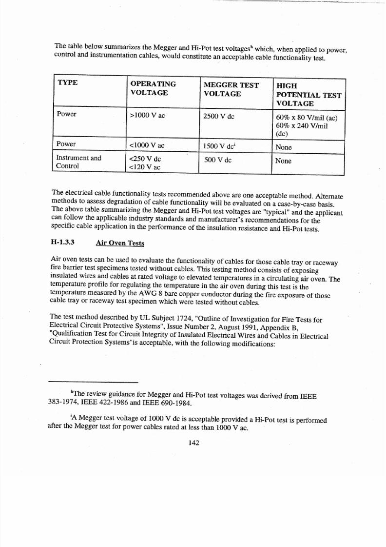
7/28/2019 Fire Protection Guide
http://slidepdf.com/reader/full/fire-protection-guide 140/167
The table below summarizes the Megger and Hi-Pot test voltages' which, when applied to power,control and instrumentation cables, would constitute an acceptable cable functionality test.
TYPE OPERATING MEGGER TEST HIGH
VOLTAGE VOLTAGE POTENTIAL TEST __...._VOLTAGE
Power >1000 V ac 2500 V dc 60% x 80 V/mil (ac)
60% x 240 V/mil(dc)
Power <1000 V ac 1500 V dc' None
Instrument and <250 V dc 500 V dc NoneControl <120 V ac
The electrical cable functionality tests recommended above are one acceptable method. Alternatemethods to assess degradation of cable functionality will be evaluated on a case-by-case basis.The above table summarizing the Megger and Hi-Pot test voltages are "typical" and the applicantcan follow the applicable industry standards and manufacturer's recommendations for thespecific cable application in the performance of the insulation resistance and Hi-Pot tests.
H-1.3.3 Air Oven Tests
Air oven tests can be used to evaluate the functionality of cables for those cable tray or racewayfire barrier test specimens tested without cables. This testing method consists of exposing
insulated wires and cables at rated voltage to elevated temperatures in a circulating air oven. Thetemperature profile for regulating the temperature in the air oven during this test is thetemperature measured by the AWG 8 bare copper conductor during the fire exposure of thosecable tray or raceway test specimen which were tested without cables.
The test method described by UL Subject 1724, "Outline of Investigation for Fire Tests forElectrical Circuit Protective Systems", Issue Number 2, August 1991, Appendix B,"Qualification Test for Circuit Integrity of Insulated Electrical Wires and Cables in ElectricalCircuit Protection Systems"is acceptable, with the following modifications:
'The review guidance for Megger and Hi-Pot test voltages was derived from IEEE383-1974, IEEE 422-1986 and IEEE 690-1984.
'A Megger test voltage of 1000 V dc is acceptable provided a Hi-Pot test is performedafter the Megger test for power cables rated at less than 1000 V ac.
142
7/28/2019 Fire Protection Guide
http://slidepdf.com/reader/full/fire-protection-guide 141/167
a. During the air oven test the cables are to be energized at rated voltage. The cables are tobe monitored for conductor-to-conductor faults in multi-conductor cables andconductor-to-ground faults in all conductors.
b. The cables being evaluated should be subjected to the Megger and high potential tests,recommended above in "Cable
Insulation Tests."c. The impact force test, which simulates the force of impact imposed on the raceway by the
solid stream test, described in UL 1724, Appendix B, paragraph B3.16, is not required tobe performed.
11-1.3.4 Cable Thermal Exposure Threshold
The following analysis, which is based on determining whether a specific insulation material willmaintain electrical integrity and operability within a raceway fire barrier system during and afteran external fire exposure, is an acceptable method for evaluating cable functionality. In order todetermine cable functionality, it is necessary to consider
the operating cable temperatures withinthe fire barrier system at the onset of the fire exposure and the thermal exposure threshold (TET)temperature of the cable. For example, if the TET of a specific thermoplastic cable insulation(Brand X) is 149°C [300'F] and the normal operating temperature within the fire barrier systemis 66°C [I50°F], then the maximum temperature rise within the fire barrier system should notexceed 83°C [150'F] during exposure to an external fire of a duration equal to the required fireresistance rating of the barrier. For this example the TET limit for Brand X cable is 83°C [150°F]above the cable operating temperatures within the fire barrier system at the onset of the externalfire exposure. The cable TET limils in conjunction with a post test visual cable inspection andthe Hi-Pot test described above should readily demonstrate the functionality of the cable circuitduring and after a fire.
The normal cable operating temperature can be determined by loading cable specimens installedwithin a thermal barrier system in the test configuration with rated voltage and current. The TETtemperature limits for most cable insulation may be obtained from the manufacturer's publisheddata which is given as the shon-circuit rating limit. With the known TET and normal operatingtemperature for each thermal barrer system configuration, the maximum temperature rise limitwithin a fire barrier system may then be determined.
143
7/28/2019 Fire Protection Guide
http://slidepdf.com/reader/full/fire-protection-guide 142/167
APPENDIX I: EQUIVALENCY
This appendix provides guidance and previously accepted examples of the use of equivalency inevaluating fire protection and safe shutdown features.
1-1.1Process Monitoring Instrumentation
Section III.L.2.d of Appendix R to 10 CFR Part 50 states that "the process monitoringfunction should be capable of providing direct readings of the process variables necessaryto perform and control" the reactivity control function. Regulatory Positions C.5.3 andC.5.4 of this guide provides a listing of instrumentation acceptable to and preferred by thestaff to demonstrate compliance with this provision. While this guidance provides anacceptable method for compliance with the regulation, it does not exclude otheralternative methods of compliance. Accordingly, a licensee may propose to the staff alternative instrumentation to comply with the regulation (e.g., boron concentrationindication). While such a submittal is not an exemption request, it should be justified
based on a technical evaluation!"
1-1.2 Fire Area Boundaries
The term "fire area" as used in Appendix R means an area sufficiently bounded towithstand the hazards associated with the area and, as necessary, to protect importantequipment within the area from a fire outside the area. In order to meet the regulation, firearea boundaries need not be completely sealed floor-to-ceiling, wall-to-wall boundaries.However, all unsealed openings should be identified and considered in evaluating theeffectiveness of the overall barrier. Where fire area boundaries are not wall-to-wall, floorto-ceiling boundaries with all penetrations sealed to the fire rating required of theboundaries, licensees should perform an
evaluation to assess the adequacy of fireboundaries in their plants to determine if the boundaries will withstand the hazardsassociated with the area. This analysis should be performed by at least a fire protectionengineer and, if required, a systems engineer. Although not required, licensees maysubmit their evaluations for staff review and concurrence. However, if certain cablepenetrations were identified as open SER items at the time Appendix R became effective,Section III.M of the rule applies (see 10 CFR 50.48(b)), and any variation from therequirements of Section III.M requires an exemption. In any event, these analyses shouldbe retained by the licensees for subsequent NRC audits.491
1-1.3 Automatic Detection and Suppression
Sections IlI.G.2.b and III.G.2.c of Appendix R state that "In addition, fire detectors andautomatic fire suppression system shall be installed in the fire area..." Other provisions of Appendix R also use the phrase" fire detectors and an automatic fire suppression systemin the fire area..." (see e.g., Section III.G.2.e).
In order to comply with these provisions, suppression and detection sufficient to protectagainst the hazards of the area should be installed. In this regard, detection and
144

7/28/2019 Fire Protection Guide
http://slidepdf.com/reader/full/fire-protection-guide 143/167
suppression providing less than full area coverage may be adequate to comply with theregulation. Where full area suppression and detection is not installed, licensees shouldperform an evaluation to assess the adequacy of partial suppression and detection toprotect against the hazards in the area. The evaluation should be performed by a fireprotection engineer and, if required, a systems engineer. Although not required, licenseesmay submit their
evaluations to the staff for review and concurrence. In any event, theevaluations should be retained for subsequent NRC audits. Where a licensee is providingno suppression or detection, and exemption should be requested.492
145
------

7/28/2019 Fire Protection Guide
http://slidepdf.com/reader/full/fire-protection-guide 144/167
APPENDIX J: GUIDANCE SOURCE CITATIONS
146
.................

7/28/2019 Fire Protection Guide
http://slidepdf.com/reader/full/fire-protection-guide 145/167
1. BTP CMEB 9.5.1, C. .a [partial].
2. BTP CMEB 9.5.1, C.l.a(2) [partial].
3. 10 CFR 50.48 (a) [partial].
4. 10 CFR 50.48 (a) [partial].
5. 10 CFR 50.48(a).
6. 10 CFR 50.48 (a).
7. 10 CFR 50.48 (a).
8. BTP CMEB 9.5.1, C.1.e ; BTP ASB 9.5-1, C.1.e. The BTP position was used in part.Since this proposed guide applies to operating reactors, certain elements from the textrelated to initial fuel receipt and loading were excluded. The term "decommissioning"
was added as new text.9. Appendix R, II.A; BTP CMEB 9.5.1, C.1.a(1) [partial]
10. BTP CMEB 9.5.1, C. 1.a(3) [partial]
11. BTP CMEB 9.5.1, C. 1.a(4) [partial]
12. BTP CMEB 9.5.1, C.1.a(4) [partial]
13. BTP CMEB 9.5.1, C.l.a(7)[partial]
14. Modified per AppendixR, II.K [partial] and BTP CMEB 9.5-1, C.2.d
15. Final sentence only - Information Notice 91-77; Information Notice 95-48
16. Appendix R, II.B; BTP CMEB 9.5.1, C.l.b [partial].
17. BTP CMEB 9.51, C.l.b [partial]; BTP ASB 9.5-1, C.l.b(5) [partial]
18. New text.
19. 10 CFR 50.48 (a).
20. New text
21. New text
22. New text.
23. Generic Letter 92-08.
24. Generic Letter 86-10, Item F; BTP CMEB 9.5-1, C.2.j, C.2.k,.
7/28/2019 Fire Protection Guide
http://slidepdf.com/reader/full/fire-protection-guide 146/167
25. Generic Letter 91-18, Attachment 1, Section 4.7.
26. Appendix R, II.A; BTP CMEB 9.5-1, C.t.a(l) [partial]
27. New text.
28. BTP CMEB 9.5-1, C.l.a(3) [partial]
29. BTP CMEB 9.5.1, C.1.a(5) [partial]
30. BTP CMEB 9.5.1, C. 1.a(5) [partial]
31. BTP CMEB 9.5.1, C.1.a(5) [partial]
32. BTP CMEB 9.5.1, C.1.a(5) [partial]
33. New text.
34. Inspection Manual 64704, 02.05
35. New text.
36. Inspection Manual 64704, 02.02.c.3.
37. New text.
38. Inspection Manual 64704, 02.05
39. Inspection Manual 6 4 7 04,02.02.c.4
.40. GL 93-03
41. Appendix R, HII.
42. BTP CMEB 9.5-1, C.3 [partial]. Section C.3.d of the BTP describes positions regardingfire brigade training.
43. BTP CMEB 9.5-1, C. .a. Section C.1.a(4)(f)v includes positions relevant to the trainingof the fire brigade.
44. BTP CMEB 9.5-1, C.3 [partial]. Section C.3.d of the BTP describes positions regardingfire
brigade training. The position is revised to accommodate changes to referencedstandards.
45. BTP CMEB 9.5-1, C.1.a(5)(b) [partial]
46. Appendix R, III.H
47. BTP CMEB 9.5-1, C.3.b [Partial]
48. Appendix R, III.H
7/28/2019 Fire Protection Guide
http://slidepdf.com/reader/full/fire-protection-guide 147/167
49. BTP CMEB 9.5-1, C.3 [partial]. Section C.3.d of the BTP describes positions regardingfire brigade training.
50. BTP 9.5-1, C.3 [partial]. Section C.3.d of the BTP describes positions regarding the firebrigade. Subjects include Drills
51. BTP CMEB 9.5-1, B.2
52. Appendix R, II.H
.53. BTP 9.5-1, C.3 [partial]. Section C.3.d of the BTP describes positions regarding the firebrigade. Subjects include Drills
54. Appendix R, IfI.L
55. BTP 9.5-1, C.3. Section C.3.d of the BTP describes positions regarding the fire brigade.Subjects include Drills
56. GL 82-21, Enclosure 2; BTP CMEB 9.5-1, C.4; BTP ASB 9.5-1, C.3
57. GL 82-21, Enclosure 2; BTP CMEB 9.5-1, C.4; BTP ASB 9.5-1, C.3
58. Generic Letter 86-10, Paragraph F
59. New text.
60. Generic Letter 86-10, Enclosure 2, 8.3
61. This information was extracted from an example enclosure to followup RAIs to Generic
Letter 92-08.
62. New text.
63. Generic Letter 86-10, Paragraph C
64. Generic Letter 86-10, Enclosure 2, 8.20 and 8.21
65. New text.
66. New text.
67. Generic Letter 86-10, Paragraph E. Reference to NUREG 1022 is new text.
68. New text
69. New text on code equivalency that was derived from NFPA code language.
70. Generic Letter 86-10, Enclosure 2, 8.9.
71. Appendix R, I1I.K [partial].
7/28/2019 Fire Protection Guide
http://slidepdf.com/reader/full/fire-protection-guide 148/167
72. BTP ASB 9.5-1, C.2 [ partial]
73. New text
74. Appendix R, IILK [partial]
75. BTP CMEB 9.5-1, C.2.a, b and c [partial]
76. Appendix R, III.K [partial]
77. Appendix R, fl.C.2
78. BTP CMEB 9.5-1, C.8.b; BTP ASB 9.5-1, C.7.b
79. BTP CMEB 9.5-1, C.8.c; BTP ASB 9.5-1, C.7.b
80. BTP ASB 9.5-1, C.6 [ partial]; BTP CMEB 9.5-1, C.2 [partial]
81. BTP CMEB 9.5-1, C.5.d(3).
82. BTP ASB 9.5-1, C.6 [ partial]
83. BTP CMEB 9.5-1, C.2.i [partial]
84. BTP CMEB 9.5-1, C.8.d; BTP ASB 9.5-1, C.7.b
85. New text.
86. BTP CMEB 9.5-1, C.5.d(4); BTP ASB 9.5-1, C.4.b(4)
87. BTP CMEB 9.5-1, C.5.e(5)
88. BTP CMEB 9.5-1, C.5.d(1) [partial]
89. Adapted from "NRC Inspection Manual Chapter 88055 - FIRE PROTECTION"
90. BTP CMEB 9.5-1, C.7.r
91. BTP CMEB 9.5-1, C.5.d(2) [partial]
92. BTP CMEB 9.5-1, C.5.e(5)
93. Source is April 1996 Draft for Public Comment version of SRP (as approved by theNRC in a letter to the BWR Owners Group dated 7/13/87, and the NRC SER for theDresden Mobile Volume Reduction System dated 8/13/86).
94. Appendix R, III.K [partial]
95. BTP APCSB 9.5-1, Appendix A, B.3(a)
96. BTP CMEB 9.5-1, C.2.e [partial]; BTP ASB 9.5-1, C.6(c)(1) [partial]

7/28/2019 Fire Protection Guide
http://slidepdf.com/reader/full/fire-protection-guide 149/167
97. NRC Inspection Manual Chapter 64704, Inspection Requirement 03.02.d.1
98. Information Notice 91-17
99. BTP CMEB 9.5-1, C.2.g [partial]; BTP ASB 9.5-1, C.6(b)(2) [partial]
100. NRC Inspection Manual Chapter 64704, Inspection Requirements 02.02.d.2. and03.02.d.3
101. Appendix R, III.K [partial]
102. BTP CMEB 9.5-1, C.2.a [partial]
103. BTP CMEB 9.5-1, C.2.h [partial]
104. Appendix R, II.C.6
105. BTP CMEB 9.5-1, C.2.j and C.2.k [partial]; NRC Insp Proc. 64704, c.l[partial]
106. BTP CMEB 9.5-1, C.2.j and C.2.k [partial]
107. GDC 3
108. Appendix R, III.F; BTP CMEB 9.5-1, B. 1; BTP ASB 9.5-1, B. 1
109. GL 83-033, Position 1; GL 86-10, Enclosure I Item 5
110. BTP CMEB 9.5-1, C.6.a; BTP ASB 9.5-1, C.1
111. BTP CMEB 9.5-1, C.l.c(3) [partial]
112. BTP CMEB 9.5-1, C.l.c (4) [partial]
113. BTP CMEB 9.5-1, C.5.e(2); BTP CMEB 9.5-1, C.7.c
114. BTP CMEB 9.5-1, C.7.b [partial]
115. BTP CMEB 9.5-1; C.7.d
116. BTP CMEB 9.5-1, C.7.e
117.BTPCMEB 9.5-1, C.7.f
118. BTP CMEB 9.5-1, C.7.g
119. BTP CMEB 9.5-1, C.7.i
120. BTP CMEB 9.5-1, C.7.k
121. BTP CMEB 9.5-1, C.7.1 and C.7.m
122. BTP CMEB 9.5-1, C.7.n

7/28/2019 Fire Protection Guide
http://slidepdf.com/reader/full/fire-protection-guide 150/167
123. BTP CMEB 9.5.1, Rev 2, Paragraph C.6.b(9)(partial); 10 CFR 50, Appendix R, IIA(partial); BTP ASB 9.5.1, Rev 1, Paragraph C.5.b(4) (partial)
124. BTP CMEB 9.5.1, Rev 2, Paragraph C.6.b(11); 10 CFR 50, Appendix R, III.A (partial)
125. BTP CMEB 9.5.1, Rev 2, Paragraph C.6.b(9) (partial); 10 CFR 50, Appendix R, III.A(partial); BTP ASB 9.5.1, Rev 1, Paragraph C.5.b(4) (partial).
126. BTP CMEB 9.5.1, Rev 2, Paragraph C.6.b(l0) (partial); 10 CFR 50, Appendix R, III.A(partial); BTP ASB 9.5.1, Rev 1,Paragraph C.5.b(4) (partial).
127. BTP CMEB 9.5.1, Rev 2, Paragraph C.6.b(12); BTP ASB 9.5-1, Rev 1, ParagraphC.5.b(6) (partial); The wording of this position changed between Rev 1 and Rev 2 of theBTP. Rev 1 specifies "two intakes" with "one hundred percent capacity." Rev 2 onlyspecifies "separate redundant suctions in one or more intake structures." The position asstated in Rev 2 was used.
128. BTP CMEB 9.5.1, Rev 2, Paragraph C.6.b(12) (partial) - BTP ASB 9.5-1, Rev 1,Paragraph C.5.b(6) (partial)
129. BTP CMEB 9.5.1, Rev 2, Paragraph C.6.b(14) (partial); 10 CFR 50, Appendix R, Ill.A(partial)
130. BTP CMEB 9.5.1, Rev 2, Paragraph C.6.b(5) (partial). The portion of C.6.b(5) related tothe sharing of yard loops at multi-unit sites was incorporated in Section 3.2.3. - BTP ASB9.5.1, Rev 1, Paragraph C.5.b(2) (partial)
131. New position based on BUL 81-03, and GL 89-13, Supplement I - BUL 81-03 concernedblockage of water supplies by clams and mussels and requested
licensees to take action toensure lines were not fouled. GL 89-13 documented recommended approaches toresolving Generic Issue 51 which addressed biofouling of raw service water systems. Therecommendations included biocide treatment and periodic flushing and testing of systemsthat were supplied from raw water sources. Supplement 1to GL 89-13 indicated that theconcerns and recommendations of GL 89-13 could be applied to fire protection systemsthat had raw water supplies.
132. BTP CMEB 9.5.1, Rev 2, Paragraph C.6.c(4) (partial); BTP CMEB 9.5.1, Rev 2,Paragraph C.1.c(3) (partial); BTP ASB 9.5.1, Rev 1, Paragraph C.5.c(4) (partial); BTPASB 9.5.1, Rev 1, Paragraph C.l.c(3) (partial)
133. BTP CMEB 9.5.1, Rev 2, Paragraph C.6.b(6) (partial) - BTP ASB 9.5.1, Rev 1,Paragraph C.5.b(3) (partial)
134. BTP CMEB 9.5.1, Rev 2, Paragraph C.6.b(6) (partial); BTP ASB 9.5.1, Rev 1, ParagraphC.5.b(3) (partial).
135. BTP CMEB 9.5.1, Rev 2, Paragraph C.6.b(6) (partial); BTP ASB 9.5.1, Rev 1, ParagraphC.5.b(3) (partial)
7/28/2019 Fire Protection Guide
http://slidepdf.com/reader/full/fire-protection-guide 151/167
136. BTP CMEB 9.5.1, Rev 2, Paragraph C.6.b(6) (partial); BTP ASB 9.5.1, Rev 1, ParagraphC.5.b(3) (partial)
137. BTP CMEB 9.5.1, Rev 2, Paragraph C.6.b(6) (modified); BTP ASB 9.5.1, Rev 1,Paragraph C.5.b(3) (partial)
138. BTP CMEB 9.5.1, Rev 2, Paragraph C.6.b(1) (partial)
139. BTP CMEB 9.5.1, Rev 2, Paragraph C.6.b(1) (partial)
140. BTP CMEB 9.5.1, Rev 2, Paragraph C.6.b(1) (partial)
141. BTP CMEB 9.5.1, Rev 2, Paragraph C.6.b(2) (partial). The portion of C.6.b(2) related toisolation was incorporated in Section 3.2.4. - BTP ASB 9.5. 1, Rev 1, Paragraph C.5.b(4)(partial)
142. BTP CMEB 9.5.1, Rev 2, Paragraph C.6.c(2) (partial). Changed "fire water systems" to
"fire mains and water-based fire suppression systems" to be consistent with outlineterminology. - BTP ASB 9.5.1, Rev 1, Paragraph C.5.c(2), (partial) - BTP ASB 9.5-1Appendix A, Paragraph E.3(b)
143. BTP CMEB 9.5.1, Rev 2, Paragraph C.6.b(4) (partial). Note that there is a typographicalerror in C.6.b(4); BTP ASB 9.5.1, Rev 1,Paragraph C.5.b(1) (partial)
144. BTP CMEB 9.5.1, Rev 2, Paragraph C.6.b(5) (partial). The portion of C.6.b(5) related tothe sharing of water supplies at multi-unit sites was incorporated in Section 3.2.1.; BTPASB 9.5.1, Rev 1, Paragraph C.5.b(2) (partial)
145. BTP CMEB 9.5.1, Rev 2, Paragraph C.6.b(2) (partial). The portion of C.6.b(2) related tocontrol valve visual indication was incorporated in Section 3.2.3; 10 CFR 50, AppendixR, II.1B and III.C (partial); BTP ASB 9.5.1, Rev 1, Paragraph C.5.b(4) (partial)
146. BTP CMEB 9.5.1, Rev 2, Paragraph C.6.b(3), (partial); 10 CFR 50, Appendix R, II.1Band III.C (partial)
147. BTP CMEB 9.5.1, Rev 2, Paragraph C.6.c(1) (partial). Changed "a crack in a moderateenergy line" to "a line break" (editorial). Changed "'plantunderground water main" to"ýyard main system" to be consistent with other references to the yard main. - BTP ASB9.5.1, Rev 1, Paragraph C.5.c(1) (partial)
148. Appendix R, fl.C.4; GDC 3. Text was revised to include the fire hazard analysis as thebasis for determining suppression requirements.
149. BTP CMEB 9.5.1, Rev 2, Paragraph C.6.c(1) (partial). Changed to refer more generally to"water-based suppression systems" rather than "sprinkler systems." - BTP ASB 9.5.1,Rev 1, Paragraph C.5.c(I) (partial); 10 CFR 50, Appendix A, GDC 3 (partial)
150. BTP CMEB 9.5.1, Rev 2, Paragraph C.6.c(3) (partial). Wording was adapted to bespecific to sprinkler and spray systems. - BTP ASB 9.5.1, Rev 1, Paragraph C.5.c(3)(partial)

7/28/2019 Fire Protection Guide
http://slidepdf.com/reader/full/fire-protection-guide 152/167
151. BTP CMEB 9.5.1, Rev 2, Paragraph C.6.c(3) (partial). C.6.c(3) describes a generalposition that "fixed water extinguishing systems should conform to requirements of appropriate standards ." Position was adapted and worded to be specific to water mistsystems. New content: added reference to NFPA 750, "Water Mist Fire ProtectionSystems," as a source of additional guidance for water mist systems - BTP ASB 9.5.1,
Rev 1, Paragraph C.5.c(3) (partial)152. BTP CMEB 9.5.1, Rev 2, Paragraph C.6.c(3) (partial). C.6.c(3) describes a general
position that "fixed water extinguishing systems should conform to requirements of appropriate standards ." Position was adapted and worded to be specific to foam systems;BTP CMEB 9.5.1, Rev 2, Paragraph C.6.c(7) (partial). The position from C.6.c(7) wassplit into separate positions for automatic and manual suppression systems (see 3.4.3).New content: Added reference to NFPA 16A, "Installation of Closed Head Foam-WaterSprinkler Systems" as an example of an acceptable foam-water system standard - BTPASB 9.5.1, Rev 1, Paragraph C.5.c(3) (partial); BTP ASB 9.5.1, Rev 1, ParagraphC.5.c(6) (partial)
153. BTP CMEB 9.5-1, C.5.a(14); BTP ASB 9.5-1, C.4.a(9)
154. BTP CMEB 9.5-I, C.5.f(7); BTP ASB 9.5-1, C.4.d(8) with addition of code reference forclean agent systems.
155. Notice 92-28, Issue 213
156. BTP CMEB 9.5-1, C.6.e; BTP ASB 9.5-1, C.5.e
157. BTP CMEB 9.5-1, C.6.e; BTP ASB 9.5-1, C.5.e
158.BTP CMEB 9.5-1, C.6.d; BTP ASB 9.5-1, C.5.d
159. Used existing guidance for C02 and Halon, with substitution of "clean agent" for producttitle and specification of NFPA 2001 as the applicable standard (BTP CMEB 9.5-1, C.6.dand e; and BTP ASB 9.5-1, C.5.d and e)
160. BTP CMEB 9.5-1, B.1; BTP ASB 9.5-1, B.1
161. BTP CMEB 9.5.1, Rev 2, Paragraph C.6.c(4) (partial); BTP ASB 9.5.1, Rev 1, ParagraphC.5.c(4) (partial); 10 CFR 50, Appendix R, III.D (partial)
162. BTP CMEB 9.5.1, Rev 2, Paragraph C.6.c(4) (partial); BTP ASB 9.5.1, Rev 1, Paragraph
C.5.c(4) (partial)
163. BTP CMEB 9.5.1, Rev 2, Paragraph C.6.c(5); BTP ASB 9.5.1, Rev 1, ParagraphC.5.c(5) (partial)
164. BTP CMEB 9.5.1, Rev 2, Paragraph C.6.c(6) (partial - see also 3.4.2.3). Changed"interior standpipe hose" to 'fire hose stored in interior plant areas" (editorial) and addedreference to NFPA Standard 1961 for fire hose; 10 CFR 50, Appendix R, III.D (partial)
165. BTP CMEB 9.5.1, Rev 2, Paragraph C.6.b(7); BTP ASB 9.5.1, Rev 1,Paragraph C.5.b(7)
7/28/2019 Fire Protection Guide
http://slidepdf.com/reader/full/fire-protection-guide 153/167
166. BTP CMEB 9.5.1, Rev 2, Paragraph C.6.b(8); BTP ASB 9.5.1, Rev 1, Paragraph C.5.b(8)
167. New text incorporating NRC comment.
168. BTP CMEB 9.5.1, Rev 2, Paragraph C.6.c(6) (partial - see also 3.4.1.4); 10 CFR 50,Appendix R, HI.D (partial)
169. BTP CMEB 9.5.1, Rev 2, Paragraph C.6.c(7) (partial). The position from C.6.c(7) wassplit into positions for automatic and manual suppression systems (see 3.3.1.3). Deletedcitation of NFPA IllB which was incorporated in NFPA 11. New content: addedreference to NFPA 11C, "Standard for Mobile Foam Apparatus,"which is a newerstandard applicable to manual fire suppression; BTP ASB 9.5.1, Rev 1, ParagraphC.5.b(6)
170. Appendix R, II.C.3; BTP CMEB 9.5-1, C.6.f; BTP ASB 9.5-1, C.5.f
171. Appendix R, II.C.5
172. Appendix R, III.N
173. BTP CMEB 9.5-1, C.l.a. Section C.l.a(4)(f)v includes positions relevant to the trainingof the fire brigade.
174. Appendix R, III.H
175. BTP CMEB 9.5-1, C.3.b [Partial]
176. Appendix R, IIl.H
177. Appendix R, III.H
178. BTP 9.5-1, C.3.c [Partial]
179. BTP CMEB 9.5-1, C.7.a(2)
180. Appendix R, IIL.K
181. BTP CMEB 9.5-1, C.2 [Partial]
182. BTP CMEB 9.5-1, B.2 [partial]
183. Appendix R, II1.L
184. BTP 9.5-1, C.3.d.(7) [Partial]
185. New text.
186. New text.
187. BTP CMEB 9.5-1, C.6.b(8)
......-
7/28/2019 Fire Protection Guide
http://slidepdf.com/reader/full/fire-protection-guide 154/167
188. BTP CMEB 9.5-1, C.3.d(1)(1)
189. NUREG-0654, Rev. 1, II.O
190. NUREG-0654, Rev. 1, H.0
191. New text in part, consistent with BTP CMEB 9.5-1, C.2.o(6).
192. New text.
193. New text, in part, consistent with BTP CMEB 9.5-1, C.2.o(6) and with NUREG-0654,II.A.2.a.
194. BTP CMEB-9.5-1, Section C.3.d(7)(d)
195. New text.
196. New text - reference source is 10 CFR 50.47 and Appendix E to Part 50 (norequirementsexplicitly stated therein)..
197. GDC 3
198. CMEB 9.5-1, C.5.a(9) [partial]; ASB 9.5-1, C.4.a(4) [partial]
199. CMEB 9.5-1, C.5.a(10); ASB 9.5-1, C.4.a(5) For plants with a Construction Permitissued prior to 7/1/76, in the event combustible materials were used in metal deck roofingdesign, acceptable alternatives are: (a) replace combustibles with non-combustiblematerials; (b) provide an automatic sprinkler system; or (c) provide ability to cover roof exterior and interior with adequate water volume and pressure. (See ASB 9.5-1,
Appendix A, D. 1(e)) This position is not incorporated as it was superceded by newguidance.
200. CMEB 9.5-1, C.5.a(9) [partial]; ASB 9.5-1, C.4.a(4) [partial]
201. CMEB 9.5-1, C.5.a(1 1); ASB 9.5-1, C.4.a(6). For plants with a Construction Permitissued prior to 7/1/76, in the event combustible materials were used for suspendedceilings, adequate fire detection and suppression systems should be provided. (See ASB9.5-1, Appendix A, D.I (f)). This position was not incorporated as it was superceded bythe new guidance.
202.Appendix R, II.C. 1
203. ASB 9.5-1, C.4.a(4)[partial]
204. GDC 3
205. New text
206. BTP CMEB 9.5-1, B.4, defines "fire area".
207. BTPCMEB 9.5-1, C.5.a(l)
......-

7/28/2019 Fire Protection Guide
http://slidepdf.com/reader/full/fire-protection-guide 155/167
208. BTP CMEB 9.5-1, B.3; BTP ASB 9.5-1, B.3. Used wording directly from outline,supported by wording from source documents: "The fire hazard analysis should be themechanism to determine that fire areas have been properly selected." Also, InformationNotice 84-09 Attachment 1, Section I.
209. BTP CMEB 9.5-1, B.3; BTP ASB 9.5-1, B.3; BTPCMEB9.5-1, C.5.a(l) and (2).[partial]; BTP ASB 9.5-1, C.4.a(1) and (2) [partial].
210. GL 86-10 Enclosure 1, Item 4
211. BTPCMEB.9.5-1, C.5.a(l) [partial]; BTPASB 9.5-1, C.4.a(l) [partial]; BTPASB9.5-1, App. A, D. 1 (j) [partial], specify 3-hour rating for fire area boundaries.
212. Reference to C.4.2.1 to address GL 86-10 Enclosure 2, 8.8.
213. GL 86-10 Enclosure 2, 3.5.2
214. GL 86-10 Enclosure 2, 3.1.3 [partial]
215. GL 86-10 Enclosure 2, 3.1.4 [partial]
.216. New text.
217. New text.
218. GL 83-33 Enclosure, Item 2
219. GL 86-10, Enclosure 2. 3X2
220. GL 86-10 Enclosure 2. 3. 1.4 with minor changes to verb cases and "would" to "should"and added footnote dtcu•ss•ng "design basis fire".
221. BTP CMEB 9.5-1. B.3- Issuc 74: BTP ASB 9.5-1, B.3
222. Bulletin 77-08 [partialj) with addition of fire suppression access to address outlinestatement regarding fire brigade.
223. Bulletin 77-08, DLscussion ol Requirements
224. BTP CMEB 9.5-1, C.5.a(6} and (7) [partial]; BTP ASB 9.5-1, C.4.a(l1) and (12)[partial]
225. Bulletin 77-08 [partial]
226. New text.
227. BTP ASB 9.5-1, C.4.c(5) [partial]; BTP CMEB 9.5-1, C.5.e(3) [Partial]. Reference toIEEE Std 1202 included. Cable flame test method has been moved from IEEE Std 383 toStd 1202.
228. BTP ASB 9.5-1 Appendix A, D.3 (f)
7/28/2019 Fire Protection Guide
http://slidepdf.com/reader/full/fire-protection-guide 156/167
229. BTP ASB 9.5-1, C.4.c(1) [partial]); BTP CMEB 9.5-1, C.5.e (1) [Partial]
230. BTP ASB 9.5-1, C.4.c(6) [partial]; BTP CMEB 9.5-1, C.5.e(4) [Partial]
231. BTP ASB 9.5-1, C.4.c(2) [partial]; BTP CMEB 9.5-1, C.5.e(2) [Partial]
232. BTP ASB 9.5-1, C.4.c(2) [partial]; BTP CMEB 9.5-1, C.5.e(2) [Partial]
233. BTP ASB 9.5-1, C.4.c(2) [partial]; BTP CMEB 9.5-1, C.5.e(2) [Partial]
234. BTP ASB 9.5-1, C.4.c(2) [partial]; BTP CMEB 9.5-1, C.5.e(2) [Partial]
235. BTP ASB 9.5-1, C.4.c(2) [partial]; BTP CMEB 9.5-1, C.5.e(2) [Partial]
236. Memo, Mattson to Eisenhut (7/22/83)
237. Memo, Mattson to Eisenhut (7/22/83)
238. BTP ASB 9.5-1, App A, D.3(c)
239. New text based on the principles of "improved risk" or "highly protected risk," and staff review of the Individual Plant Examination of External Events.
240. BTP CMEB 9.5-1, B.3; BTP ASB 9.5-1, B.3
241. BTP CMEB 9.5-1, C.5.f(3); BTP ASB 9.5-1, C.4.d(3)
242. BTP CMEB 9.5-1, C.5.f(2); BTP ASB 9.5-1, C.4.d(2)
243. BTP CMEB 9.5-1, C.5.f(5); BTPASB 9.5-1, C.4.d(5)
244. BTP CMEB 9.5-1, C.5.f(7); BTP ASB 9.5-1, C.4.d(8)
245. New text
246. BTP CMEB 9.5-1, C.5.f(4); BTP ASB 9.5-1, C.4.d (4);
247. New text.
248. BTP CMEB 9.5-1, C.5.f(1); BTP ASB 9.5-1, C.4.d(1).
249.New text
250. New text.
251. BTP CMEB 9.5-1, B.3; BTP ASB 9.5-1, B.3
252. New text
253. BTP CMEB §.5-1, C.5.f(6); BTP ASB 9.5-1, C.4.d(6).
7/28/2019 Fire Protection Guide
http://slidepdf.com/reader/full/fire-protection-guide 157/167
254. BTP APCSB 9.5-1, Appendix A, D.4.f. Specific reference to the requirement formasonry construction of 3-hour rating was not included. The fire rating should be inaccordance with code requirements for life safety such as NFPA 101for the type of stair.
255. Information Notice 83-69.
256. Information Notice 89-52
257. New text.
258. BTP CMEB 9.5-1, C.5.a [partial]; BTP ASB 9.5-1, C.4.a [partial]
259. BTP ASB 9.5-1, B.2; BTP CMEB 9.5-1, B.2
260. New text.
261. New text. (Note that RG 1.120 drafts and fire protection BTPs do not specifically addressthe topic of lighting
for life safety.) NFPA 101 is referenced for this purpose in NRCInspection Manual 88055, Chapter IMSB.
262. BTP ASB 9.5-1, C.4.e; BTP CMEB 9.5-1, C.5.g, with additions from other sourcedocuments as indicated.
263. Appendix R, III.J; BTP wording revised to be consistent with wording in Appendix R.
264. Discussion regarding lighting levels from GL 86-10, Enclosure 2, 4.1
265. New text developed to address the deficiencies described in Information Notice 95-36.
266. BTP ASB 9.5-1, C.4.e; BTP CMEB 9.5-1, C.5.g
267. TI 2 515/62-04.03.a.2 [partial]; IP 64100, 02.03.a.2[partial], with addition of introductorysentence to clarify why guidance is provided for configurations that do not comply withAppendix R.
268. Adapted from Standard Review Plan, Section 9.5.2, Communications Systems.
269. BTP ASB 9.5-1, C.4.e [partial]; BTP CMEB 9.5-1, C.5.g [partial]
270. Appendix R, II.C.1 - replacing "fire" with "explosion".
271. Appendix R, II.C.2 replacing "fire" with "explosion".
272. BTP ASB 9.5-1, C.4.c (7) and BTP CMEB 9.5-1, C.5.e (5) modified to incorporate BTPCMEB 9.5-1, C.8.a.
273. New text developed based on discussion in Generic Letter 93-06.
274. Adapted from NRC Inspection Manual Chapter 88055, Inspection Requirement 02.04,1(d).
.........- -

7/28/2019 Fire Protection Guide
http://slidepdf.com/reader/full/fire-protection-guide 158/167
275. Adapted from NRC Inspection Manual Chapter 88055, Inspection Requirement 02.04,6(d).
276. Text based on SRP 11.3, Section B.6 and RG 1.143, Position C.2.1.2.
277. BTP CMEB 9.5-1, B.4 [partial]
278. GL 86-10, Enclosure 2, 3.2.2
279. CMEB 9.5-1, C.5.a(9) [partial]; ASB 9.5-1, C.4.a(4) [partial]
280. New text.
281. Adapted from BTP CMEB 9.5-1, B.4 [partial]
282. Adapted from BTP ASB 9.5-1, C.4.a(10) [partial], BTP CMEB 9.5-1, C.5.a(3) [partial],and GL 86-10 Supplement 1, Enclosure 1, IV [partial]
283. GL 86-10 Supplement 1, Enclosure 1, IV [partial], modified by removal of the term"nationally recognized laboratory" as recommended in NUREG 1552.
.284. GL 86-10, Enclosure 2, 3.2.3
285. Appendix R, III.N
286. GL 86-10 Supplement 1.Enclosure 1, IV [partial] modified by removal of the term"nationally recognized lab ratory" as recommended in NUREG 1552.
287. Information Notice 83-69
288. Information Notice 89-52
289. Information Notice 89-52
290. Information Notice 88-(W. Appendix A, Item B. 1 [partial]
291. BTP ASB 9.5-1, C.4.a( l(I~parnal]: BTP CMEB 9.5-1, C.5.a(3) [partial], modified byremoval of the term "non'ombustible" as recommended in NUREG 1552.
292. Information Notice 88-44. Appendix A, Items B.4 and B.5 [partial]
293. Text developed based on Information Notice 88-56
294. GL 86-10 Supplement 1,Enclosure 1, II and IV [partial]
295. Appendix R, III.M - applicable to penetration design; BTP ASB 9.5-1, C.4.a(10) [partial];BTP CMEB 9.5-1, C.5.a(3) [partial]; GL 86-10 Supplement 1, Enclosure 1, IV [partial]
296. Information Notice 88-04, Appendix A, Item B.2 [partial]
7/28/2019 Fire Protection Guide
http://slidepdf.com/reader/full/fire-protection-guide 159/167
297. Appendix R, III.M - applicable to penetration design; BTP ASB 9.5-1, C.4.a(l0)[partial];BTP CMEB 9.5-1, C.5.a(3) [partial]; GL 86-10 Supplement 1, Enclosure 1, IV [partial];Revised the text of the BTP describing testing to be applicable to the entire barrier systemand not just limited to penetrations; removed requirement for barriers to be of noncombustible material to address recommendations of NUREG 1552; and Information
Notice 88-04, Appendix A, Item C - with respect to hose stream testing [partial]
298. GL 86-10 Supplement 1, Enclosure 1, IV [partial] modified by removal of the term"nationally recognized laboratory" as recommended in NUREG 1552.
299. Information Notice 88-04, Appendix A, Item A [partial]
300. NUREG 1552, Section 5.12
301. NUREG 1552, Section 5.12
302. Appendix R, III.G.2.a - [partial]; BTP CMEB 9.5-1, C.5.b(2)(a).
303. GL 86-10, Enclosure 2, 3.3.1
304. GL 83-33, Enclosure, Item 3
305. GL 86-10, Enclosure 2, 3.3.3
306. BTP ASB 9.5-1, C.4.c(2) [partial]; BTP CMEB 9.5-1, C.5.e(2) [Partial]
307. New text.
308. New text.
309. BTP ASB 9.5-1, C.4.c(4) [partial]) - NOTE: This position does not appear in thesubsequent BTP revision.
310. GL 86-10, Enclosure 2, 3.2.1 [partial]
311. GL 86-10, Supplement 1, Enclosure 1, II [partial]
312. GL 86-10, Supplement 1, Enclosure 1, II [partial]
313. BTP ASB 9.5-1, C.4.c(5) [partial]; BTP CMEB 9.5-1, C.5.e(3) [Partial]
314. BTP ASB 9.5-1 App A, D.3 (f)
315. New text.
316. 10 CFR 50, Appendix R, III.L.1; Information Notice 84-09, Attachment 1, Section V;Generic Letter 81-12, Enclosure 1,Subsection 2
317. 10 CFR 50, Appendix R, III.L.2, III.L.5, and III.L.6; Generic Letter 86-10, Enclosure 1;BTP CMEB 9.5-1, C.5.c; Staff Memorandum, Rubenstein to Mattson, 1/7/83; GenericLetter 81-12, Enclosure 1, Subsection 3; Generic Letter 86-10, Enclosure 2, Section 5.3.6
7/28/2019 Fire Protection Guide
http://slidepdf.com/reader/full/fire-protection-guide 160/167
318. 10 CFR 50, Appendix R, Sections I and l.6.1(a)
319. Generic Letter 86-10, Enclosure 1, Item 3
320. BTP CMEB 9.5-1, B.I and C.5.b; BTP ASB 9.5-1, B.1
321. Staff Memo, RJ Mattson to RH Vollmer, dated July 2, 1982.
322. Staff Memo, RJ Mattson to RH Vollmer, dated July 2, 1982.
323. Generic Letter 81-12, Attachment 1, Section 4
324. Information Notice 84-09, Attachment 1, Section IX; Staff Memorandum, Rubenstein toMattson, 1/7/83; Generic Letter 81-12, Attachment 1, Section 4
325. Generic Letter 81-12, Attachment 1, Section 4
326. Staff Memorandum, LS Rubenstein to RI Mattson, 12/3/1982
327. New text.
328. Generic Letter 81-12, Attachment 1, Section 5
329. Information Notice 84-09, Attachment 1, Section IX; Generic Letter 81-12, Attachment 1,Section 6; Generic Letter 86-10, Enclosure 2, Section 5.3.7
330. Generic Letter 81-12, Attachment 1, Section 6
331. 10 CFR 50, Appendix R, Sections I and III.G.1 (b); BTP CMEB 9.5-1, C.5.b.
.332. 10 CFR 50, Appendix R, III.L.5; Generic Letter 86-10, Enclosure 1, Item 2; Staff Memo,RJ Mattson to RH Vollmer, dated July 2, 1982.
333. Information Notice 84-09, Attachment 1, Section XI; Staff Memo, RJ Mattson to RHVollmer, dated July 2, 1982.
334. Generic Letter 81-12, Attachment 1, Section 5
335. Generic Letter 81-12, Attachment 1,Section 7
336. 10 CFR 50, Appendix R, II.C.4
337. 10 CFR 50, Appendix R, III.G.2; BTP CMEB 9.5-1, C.5.b
338. Information Notice 84-09, Section VI; Generic Letter 86-10, Enclosure 2, 3.6.1, 3.6.2,and 3.6.3; Generic Letter 83-33, Enclosure, Item 5
339. 10 CFR 50, Appendix R, III.G.2; BTP CMEB 9.5-1, C.5.b
340. Generic Letter 86-10, Enclosure 1, Item 5

7/28/2019 Fire Protection Guide
http://slidepdf.com/reader/full/fire-protection-guide 161/167
341. 10 CFR 50, Appendix R, HI.G.2
342. 10 CFR 50, Appendix R, II.D, and III.G.3; Generic Letter 86-10, Enclosure 2, Section3.1.5; BTP CMEB 9.5-1, C.l.d; Generic Letter 81-12, Enclosure 1, Subsection 1.
343. Generic Letter 86-10, Enclosure 1, Item 6 and Enclosure 2, Section 3.1.5
344. 10 CFR 50, Appendix R, III.L.3; Information Notice 84-09, Section X
345. Generic Letter 86-10, Enclosure 2, 3.8.4
346. Temporary Instruction 2515/xxx, Appendix J; Inspection Procedure 64100
347. Generic Letter 86-10, Enclosure 2, Section 5.2.3
348. 10 CFR 50, Appendix R, Section III.L.3; Information Notice 84-09, Attachment 1,Section X; Generic Letter 81-12, Rewrite of Section 8, i.e
349. Generic Letter 81-12, Rewrite of Section 8; Generic Letter 86-10, Enclosure 2, Section5.3.8
350. NRC Staff Memo, HR Denton to SA Bernsen (Bechtel), 4/20/82; Generic Letter 86-10,Enclosure 2, Section 3.8.4
351. 10 CFR 50, Appendix R, Section III.L.5; Information Notice 84-09, Attachment 1,Section XI; Generic Letter 81-12.
352. Information Notice 84-09, Attachment 1, Section XI
353. BTP CMEB 9.5-1, C.7.a(l) and (2); BTP ASB 9.5-1, C.6.a, and Appendix A to APCSB9.5-1, F.I. The text is revised to replace "...evaluated to ensure that the integrity of theprimary coolant system and containment is not jeopardized" with "...evaluated in theFHA to ensure that the integrity of the primary coolant system and containment is not
jeopardized and the safe shutdown performance objectives described in RegulatoryPosition 5 of this Guide are met"
354. BTP CMEB 9.5-1, C.7.a(1)(f); BTP ASB 9.5-1, C.6.a, and Appendix A to APCSB 9.5-1,F. 1
355. BTP CMEB 9.5-1, C.7.a.(1)(b); Generic Letter 86-10, Enclosure 2, 3.7.1
356. 10 CFR 50, Appendix R, III.G.2.d, e, and f,
357. BTP CMEB 9.5-1, C.7.a(1); BTP ASB 9.5-1, C.6.a, and Appendix A to APCSB 9.5-1,F.1
358. BTP ASB 9.5-1, C.6.a, and Appendix A to APCSB 9.5-1, F.1
359. 10 CFR 50, Appendix R, III.D; BTP CMEB 9.5-1, C.7.a(1)(d); BTP ASB 9.5-1 (Rev 1)
360. BTP CMEB 9.5-1, C.7.a(1)(d)

7/28/2019 Fire Protection Guide
http://slidepdf.com/reader/full/fire-protection-guide 162/167
361. BTP CMEB 9.5-1, C.7.a(1)(a); BTP ASB 9.5-1, C.6.a, and Appendix A to APCSB 9.5-1,F.1
362. BTP CMEB 9.5-1, C.7.a(2); BTP ASB 9.5-1, C.6.a, and Appendix A to APCSB 9.5-1,F.1
363. BTP CMEB 9.5-1, C.7.a(1)(f); BTP ASB 9.5-1, C.6.a, and Appendix A to APCSB 9.5-1,F.1
364. BTP CMEB 9.5-1, C.7.a(1)(c); BTP ASB 9.5-1, C.6.a, and Appendix A to APCSB 9.5-1,F.1
365. BTP CMEB 9.5-1, C.7.b; BTP ASB 9.5-1, C.6.b. BTP ASB 9.5-1, C.6.b providesguidance regarding use of CO2 in the control room. BTP CMEB 9.5-1 does not allowCO2 in this application.
366. BTP CMEB 9.5-1, C.7.b; BTP ASB 9.5-1, C.6.b
367. BTP CMEB 9.5-1, C.7.b; BTP ASB 9.5-1, and Appendix A to APCSB 9.5-1, D.3;Appendix A to APCSB 9.5-1, F.2. Appendix A to APCSB 9.5-1, F.2, for Plants withapplications docketed, but not having received a construction permit by 7/1/76, statescables should not be located in concealed floor and ceiling spaces. This position iscontradictory to other versions of the BTP. This criteria is unnecessarily restrictive andhas therefore not been incorporated into the guide.
368. Appendix A to APCSB 9.5-1, F.2. The protection of safety related equipment by use of curbs, pedestals and drains was not carried forth to later versions of the BTP.
369. BTP CMEB 9.5-1, C.7.b
370. BTP CMEB 9.5-1, C.7.b; BTP ASB 9.5-1, C.6.b, and Appendix A to APCSB 9.5-1, F.2
371. BTP CMEB 9.5-1, C.7.b; BTP ASB 9.5-1, C.6.b; BTP ASB 9.5-1, Appendix A, F.2
372. BTP CMEB 9.5-1, C.7.b; BTP ASB 9.5-1, C.6.b; BTP ASB 9.5-1, Appendix A, F.2
373. BTP CMEB 9.5-1, C.7.b; BTP ASB 9.5-1, C.6.b; Appendix A to APCSB 9.5-1, F.2.Appendix A states (for plants docketed but construction permits not received) that smokedetection should automatically isolate outdoor air intakes. This provision was supercededin subsequent versions of the BTP.
374. BTP CMEB 9.5-1, C.7.b; BTP ASB 9.5-1, C.6.b; Appendix A to APCSB 9.5-1, F.2
375. BTP CMEB 9.5-1, C.7.b; BTP ASB 9.5-1, C.6.b
376. BTP CMEB 9.5-1, C.7.c; BTP ASB 9.5-1, C.6.c; Appendix A to APCSB 9.5-1, D. 1;Appendix A to APCSB 9.5-1, F.3.b. Text was revised to state "...dedicated or alternateshutdown system..." in place of "...dedicated system...".
377. BTP CMEB 9.5-1, C.7.c; BTP ASB 9.5-1, C.6.c
7/28/2019 Fire Protection Guide
http://slidepdf.com/reader/full/fire-protection-guide 163/167
378. Appendix A to APCSB 9.5-1, F.3.(b)
379. BTP CMEB 9.5-1, C.7.c; BTP ASB 9.5-1, C.6.c; Appendix A to APCSB 9.5-1, F.3.(a)
380. BTP CMEB 9.5-1, C.7.c; BTP ASB 9.5-1, C.6.c
381. Appendix A to APCSB 9.5-1, F.3.(a)
382. BTP CMEB 9.5-1, C.7.c; BTP ASB 9.5-1, C.6.c; Appendix A to APCSB 9.5-1, F.3.(a)
383. BTP CMEB 9.5-1, C.7.c; BTP ASB 9.5-1, C.6.c; Appendix Ato APCSB 9.5-1, F.3.(a)
384. Appendix A to APCSB 9.5-1, F.3.(a)
385. BTP CMEB 9.5-1, C.7.c; BTP ASB 9.5-1, C.6.c; Appendix A to APCSB 9.5-1, F.3.(a)
386. BTP CMEB 9.5-1, C.7.c; BTP ASB 9.5-1, C.6.c
387. BTP CMEB 9.5-1, C.7.d; BTP ASB 9.5-1. This section was not included in the RGoutline.
388. New text based on the principles of "highly protected risk" or "'improvedrisk," insightsobtained from the staff review of the Individual Plant Examination of External Events,and personnel safety concerns with the use of manual hose streams on energized highvoltage electrical equipment.
389. BTP CMEB 9.5-1, C.7.e; BTP ASB 9.5-1, C.6.d-r
390. BTP CMEB 9.5-1, C.7.f; BTP ASB 9.5-1, C.6.d-r
391. BTP CMEB 9.5-1, C.7.g; BTP ASB 9.5-1, C.6.d-r. Appendix A to APCSB 9.5-1, F.7contains alternatives to battery room fire barriers and suppression that were notincorporated. This guidance was superceded.
392. BTP CMEB 9.5-1, C.7.i; BTP ASB 9.5-1, C.6.d-r; Appendix A to APCSB 9.5-1 F.9
393. BTP CMEB 9.5-1, C.7.k; BTP ASB 9.5-1, C.6.d-r; Appendix A to APCSB 9.5-1, F.11
394. BTP CMEB 9.5-1, C.7.1; BTP ASB 9.5-1, C.6.d-r
395. BTP CMEB 9.5-1, C.7.m; BTP ASB 9.5-1, C.6.d-r
396. BTP CMEB 9.5-1, C.7.n; BTP ASB 9.5-1, C.6.d-r, Appendix A to APCSB 9.5-1, F.14,F.15, G.2, G.4
397. BTP CMEB 9.5-1, C.8.d
398. New text.
399. BTP CMEB 9.5-1, C.7.o; BTP ASB 9.5-1, C.6.d-r

7/28/2019 Fire Protection Guide
http://slidepdf.com/reader/full/fire-protection-guide 164/167
400. BTP CMEB 9.5-1, C.7.q; BTP ASB 9.5-1, C.6.d-r; BTP ASB 9.5-1, App. A, F.17
401. New text.
402. 10 CFR 50, Appendix R, 110.; BTP CMEB 9.5-1, C.7.a(1)(e); BTP ASB 9.5-1, C.6.a;Inspection Procedure, 64100
403. Information Notice 84-09, Attach. 1, Section XII; Memorandum, Vollmer to Eisehut
(4/1/83); Generic Letter 86-10, Enclosure 2, 6.1; Generic Letter 86-10, Enclosure 2, 6.2
.404. BTP CMEB 9.5-1, C.7.1; BTP ASB 9.5-1, C.6.d-r; BTP ASB 9.5-1,Appendix A, F.8
405. BTP ASB 9.5-1, C.6.h, and Appendix A to APCSB 9.5-1, F.8
406. New text.
407. New text.
408. BTP CMEB 9.5-1, C.5.a(12), (13). Similar guidance is also provided in BTP ASB 9.5-1,C.4.a.(8) and Appendix A to APCSB 9.5-1, D.l.h.
409. BTP ASB 9.5-1, C.6.(j) and Appendix A to APCSB, F.10
410. BTP CMEB 9.5-1, C.7.j; BTP ASB 9.5-1, C.6.d-r
411. BTP CMEB 9.5-1, C.5.d.(2), (5); BTP ASB 9.5-1, C.4.b. Similar guidance is alsoprovided in Appendix A to APCSB 9.5-1, D.2.b; Generic Letter 93-06
412. GL 93-06
413. Source is April 1996 Draft for Public Comment version of SRP (as approved by theNRC in a letter to the BWR Owners Group dated 7/13/87, and the NRC SER for theDresden Mobile Volume Reduction System dated 8/13/86).
414. BTP CMEB 9.5-1, C.5.d(2) [partial]
415. BTPCMEB 9.5-1, C.8.a
416. BTP CMEB 9.5-1, C.8.a; BTP ASB 9.5-1, C.7.a
417. New text.
418. The bullet list of attributes for a fire hazards analysis was extracted from an exampleenclosure to followup RAIs associated with Generic Letter 92-08.
419. BTP ASB 9.5-1, C.l.b[partial]
420. BTP CMEB 9.5.1, C.l.b; BTP ASB 9.5-1, C.1.d (1); GL 86-10, Enclosure 2, Section 7.2[partial]
............

7/28/2019 Fire Protection Guide
http://slidepdf.com/reader/full/fire-protection-guide 165/167
421. BTP CMEB 9.5.1, C.t.b [partial]; BTP ASB 9.5-1, C.l.d (2). NOTE: The wording of this position changed between BTP versions, but there is no technical difference in theposition.
422. BTP CMEB 9.5.1, C.l.b [partial]; BTP ASB 9.5-1, C.l.b(4) [partial]
423. BTP CMEB 9.5.1, B.3; Notice 84-09, Attachment 1, Section I
424. GL 86-10, Enclosure 2, 3.8.2
425. GL 86-10, Enclosure 2, 3.1.4 adapting text for analysis of external yard areas to apply tofire areas in general.
426. GL 86-10, Enclosure 1, Item 3[partial]
427. GDC-3; Notice 83-41; Notice 86-106; Notice 88-60
428. AppendixR, II.B; BTP CMEB 9.5.1, C.1.b [partial].
429. BTP ASB 9.5-1, C.1.b(3) [partial]. NOTE: Qualification requirements for the lead FHAengineer were dropped in later versions of the BTP. The staff believes that thequalification requirements are necessary and therefore have been incorporated into theguide.
430. New text.
431. Generic Letter 81-12, Clarification
432. Generic Letter 86-10, Enclosure 2, 5.3.1
433. Staff Memorandum, Holahan to Crutchfield, 12/4/90
434. Generic Letter 86-10, Enclosure 2, 5.3.2
435. Generic Letter 81-12, Clarification
436. Generic Letter 81-12, Clarification
437. Generic Letter 86-10, Enclosure 2, 5.3.8
438. Generic Letter 81-12, Clarification
439. Information Notice 88-45
440. Generic Letter 81-12, Clarification
441. Generic Letter 86-10, Paragraph F
442. Generic Letter 86-10, Paragraph F
443. Generic Letter 86-10, Paragraph F
....... .....
7/28/2019 Fire Protection Guide
http://slidepdf.com/reader/full/fire-protection-guide 166/167
444. Generic Letter 86-10, Paragraph F
445. Generic Letter 86-10, Enclosure 2, 8.4
446. New text.
447. Generic Letter 91-18, Attachment 1
448. SECY-99-130. Criteria from the proposed changes to 50.59 as described in the SECYpaper were added per NRC comment
449. New text developed in part from Generic Letter 86-10, Paragraph F.
450. SECY-99-130
451. 10 CFR 50.59; SECY-99-130
452. GL86-10, D
453. GL 82-21, Enclosure 2
454. GL 82-21, Enclosure 2; BTP CMEB 9.5-1, C.4; BTP ASB 9.5-1, C.3
455. BTP CMEB 9.5-1, C.4.a
456. GL 82-2 1,Enclosure 2, 1.0
457. BTP CMEB 9.5-1, C.4.b
458. GL 82-21, Enclosure 2, 2.0
459. BTP CMEB 9.5-1, C.4.c
460. GL 82-21, Enclosure 2, 3.0
461. BTPCMEB 9.5-1, C.4.d
462. GL 82-21, Enclosure 2, 4.0
463. BTP CMEB 9.5-1, C.4.e
464. GL 82-21, Enclosure 2, 5.0
465. BTP CMEB 9.5-1, C.4.f
466. GL 82-21, Enclosure 2, 6.0
467. BTP CMEB 9.5-1, C.4.g
468. GL 82-21, Enclosure 2, 7.0
469. BTP CMEB 9.5-1, C.4.h
. .......-

7/28/2019 Fire Protection Guide
http://slidepdf.com/reader/full/fire-protection-guide 167/167
470. GL 82-21, Enclosure 2, 8.0
471. GL91-18
472. BTP CMEB 9.5-1, C.4.i
473. GL 82-21, Enclosure 2, 9.0
474. BTP CMEB 9.5-1, C.4.j
475. GL 82-21, Enclosure 2, 10.0
476. GL 82-2i, Enclosure 1
477. GL 82-21, Enclosure 1
478. GL 82-21, Enclosure I
479. AL 95-06
480. AL 95-06
481. GL 82-21, Enclosure 3
482 GL 82 21 E l 3