fire detection system 1808
TRANSCRIPT

7/27/2019 Fire Detection System 1808
http://slidepdf.com/reader/full/fire-detection-system-1808 1/27

7/27/2019 Fire Detection System 1808
http://slidepdf.com/reader/full/fire-detection-system-1808 2/27
1

7/27/2019 Fire Detection System 1808
http://slidepdf.com/reader/full/fire-detection-system-1808 3/27
O2
FuelHeat
2

7/27/2019 Fire Detection System 1808
http://slidepdf.com/reader/full/fire-detection-system-1808 4/27
Class A Class B Class C Class D
3
7/27/2019 Fire Detection System 1808
http://slidepdf.com/reader/full/fire-detection-system-1808 5/27
The design of the fire detection system is differentaccording to the area which is monitored.
The purpose:
-Safety of passengers and flight crews-Economical purposes
The Fire Detection System is interconnected withother system as well.
4

7/27/2019 Fire Detection System 1808
http://slidepdf.com/reader/full/fire-detection-system-1808 6/27
The design is depends on the area on the a/c
Divide into 2:
1. Overheat and fire detection
2. Smoke detection
5

7/27/2019 Fire Detection System 1808
http://slidepdf.com/reader/full/fire-detection-system-1808 7/27
Thermo sensitive loops detect fire and trigger the warning of the Fire Detection Unit (FDU) when thetemperature reaches the threshold of the monitoredarea.
6
7/27/2019 Fire Detection System 1808
http://slidepdf.com/reader/full/fire-detection-system-1808 8/27
Two independent loops are installed in each engine.
Connected in parallel
Purpose is to prevent spurious fire warning
7
7/27/2019 Fire Detection System 1808
http://slidepdf.com/reader/full/fire-detection-system-1808 9/27
Fire–
excessive overheat / flammable fluid leaks.
Thermo-sensitive elements detect fire / overheatconditions. – trigger the fire warning by Fire Detection
Unit (FDU). ENG/APU FIRE panel (Fig. 1) includes control,
indications and test function for each engine.
8
7/27/2019 Fire Detection System 1808
http://slidepdf.com/reader/full/fire-detection-system-1808 10/27
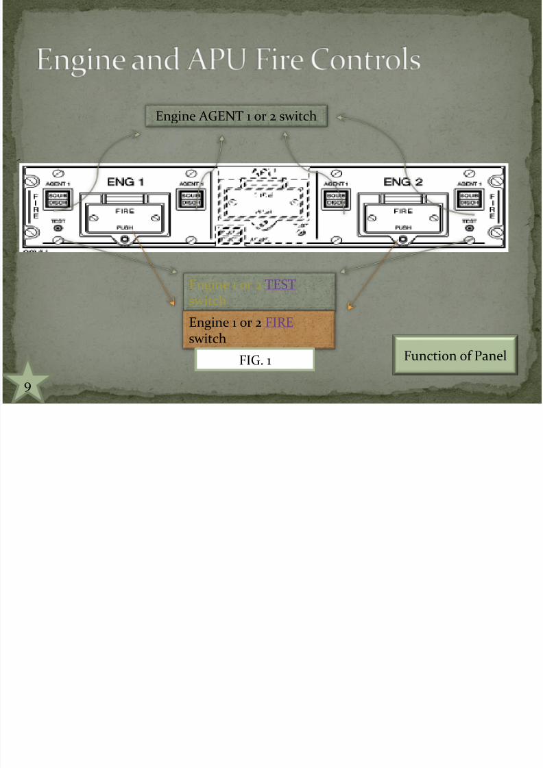
Engine AGENT 1 or 2 switch
Engine 1 or 2 TEST switch
Engine 1 or 2 FIRE switch
FIG. 1
9
Function of Panel
7/27/2019 Fire Detection System 1808
http://slidepdf.com/reader/full/fire-detection-system-1808 11/27
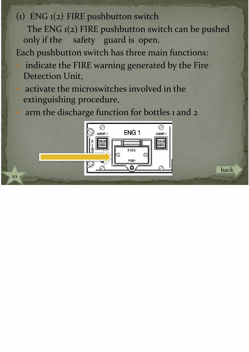
(1) ENG 1(2) FIRE pushbutton switch
The ENG 1(2) FIRE pushbutton switch can be pushed
only if the safety guard is open.Each pushbutton switch has three main functions:
indicate the FIRE warning generated by the FireDetection Unit,
activate the microswitches involved in theextinguishing procedure,
arm the discharge function for bottles 1 and 2
10back
7/27/2019 Fire Detection System 1808
http://slidepdf.com/reader/full/fire-detection-system-1808 12/27
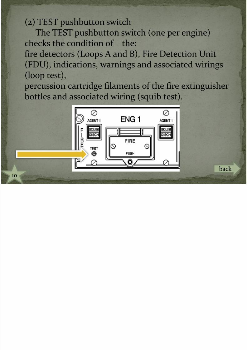
(2) TEST pushbutton switchThe TEST pushbutton switch (one per engine)
checks the condition of the:fire detectors (Loops A and B), Fire Detection Unit(FDU), indications, warnings and associated wirings(loop test),
percussion cartridge filaments of the fire extinguisherbottles and associated wiring (squib test).
10back

7/27/2019 Fire Detection System 1808
http://slidepdf.com/reader/full/fire-detection-system-1808 13/27
a FIRE warning which comes on red on the ENG 1(2)FIRE pushbutton switch after a positive fire detection
a manual test capability of the system
11
7/27/2019 Fire Detection System 1808
http://slidepdf.com/reader/full/fire-detection-system-1808 14/27
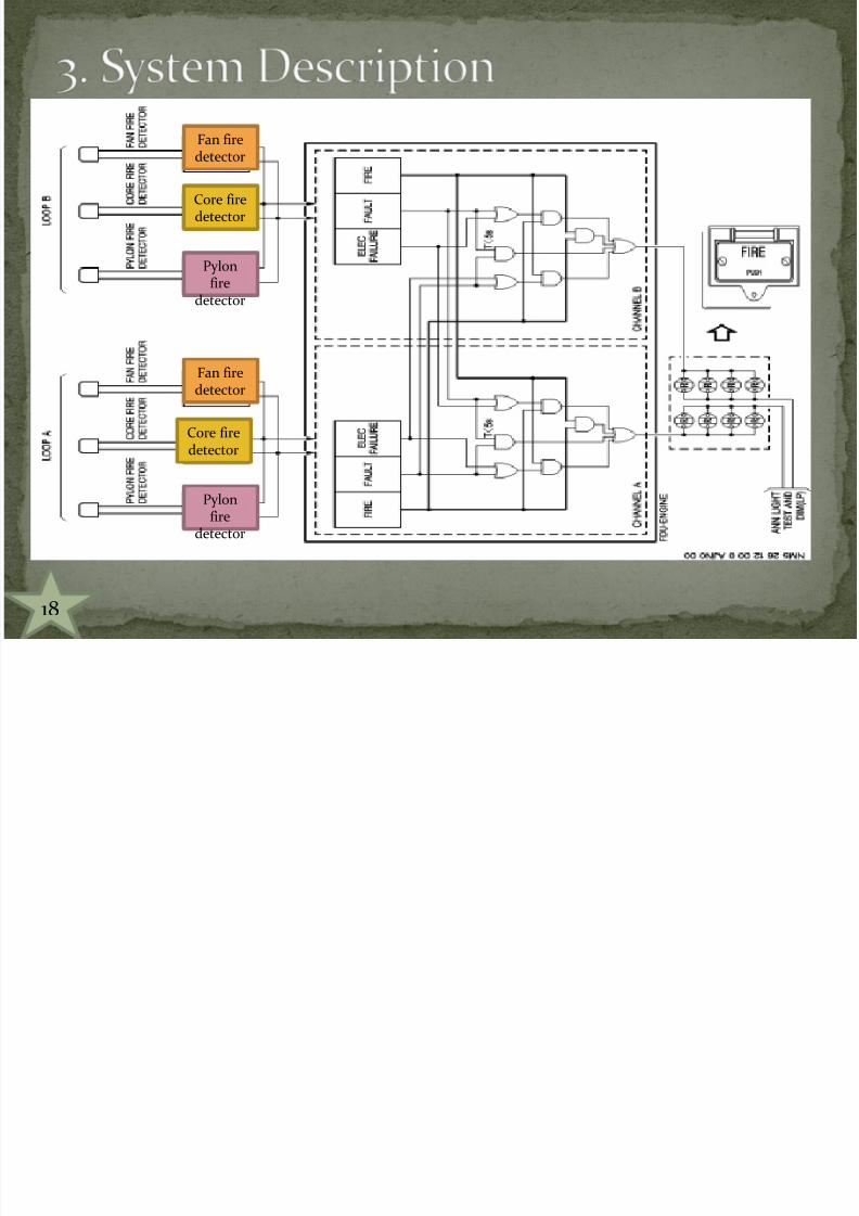
2 fire detection loops parallel in fire zones, cnnected toFDU. Each fire detection loop
comprises three detectors connected in parallel,
one FDU per engine, which processes signals from thedetectors,
an ENG/APU FIRE panel on the overhead panel withper engine:
-one ENG FIRE pushbutton switch,-one TEST pushbutton switch,
associated warnings and indications
12
7/27/2019 Fire Detection System 1808
http://slidepdf.com/reader/full/fire-detection-system-1808 15/27
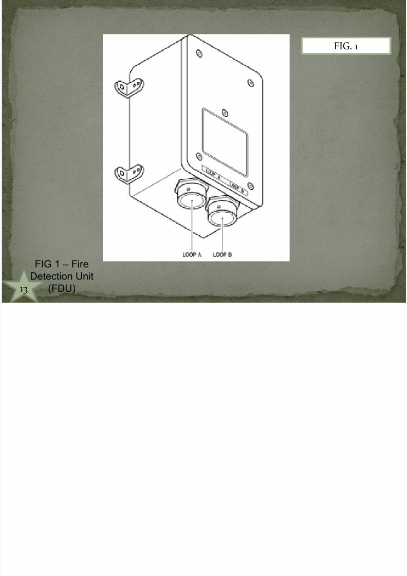
FIG. 1
FIG 1 – Fire
Detection Unit
(FDU)13

7/27/2019 Fire Detection System 1808
http://slidepdf.com/reader/full/fire-detection-system-1808 16/27
FIG. 2
A – Engine and
APU fire panel
14

7/27/2019 Fire Detection System 1808
http://slidepdf.com/reader/full/fire-detection-system-1808 17/27
FIG 3 - Pylon fire
detector
FIG. 3
15
7/27/2019 Fire Detection System 1808
http://slidepdf.com/reader/full/fire-detection-system-1808 18/27
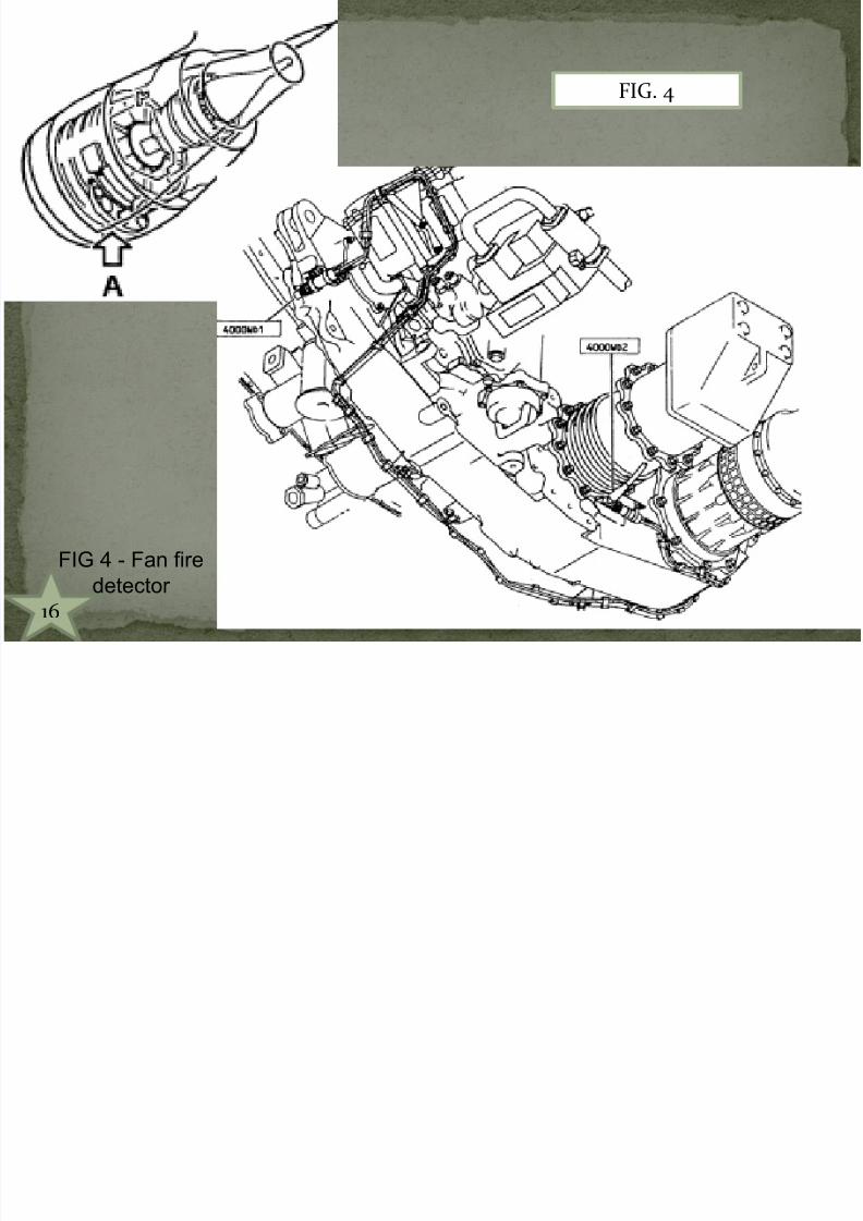
FIG. 4
FIG 4 - Fan fire
detector
16

7/27/2019 Fire Detection System 1808
http://slidepdf.com/reader/full/fire-detection-system-1808 19/27
FIG 5 - Core fire
detector
FIG. 5
17
7/27/2019 Fire Detection System 1808
http://slidepdf.com/reader/full/fire-detection-system-1808 20/27
Pylonfire
detector
Pylonfire
detector
Core firedetector
Core fire
detector
Fan firedetector
Fan fire
detector
18

7/27/2019 Fire Detection System 1808
http://slidepdf.com/reader/full/fire-detection-system-1808 21/27
The engine fire and overheat detection system gets theelectrical power from the DC system of the aircraft.
19
7/27/2019 Fire Detection System 1808
http://slidepdf.com/reader/full/fire-detection-system-1808 22/27
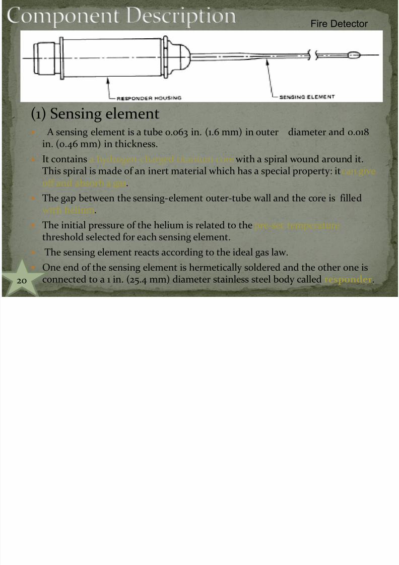
(1) Sensing element A sensing element is a tube 0.063 in. (1.6 mm) in outer diameter and 0.018
in. (0.46 mm) in thickness.
It contains a hydrogen-charged titanium core with a spiral wound around it.This spiral is made of an inert material which has a special property: it can giveoff and absorb a gas.
The gap between the sensing-element outer-tube wall and the core is filled
with helium. The initial pressure of the helium is related to the pre-set temperature
threshold selected for each sensing element.
The sensing element reacts according to the ideal gas law.
One end of the sensing element is hermetically soldered and the other one is
connected to a 1 in. (25.4 mm) diameter stainless steel body called responder.
Fire Detector
20
7/27/2019 Fire Detection System 1808
http://slidepdf.com/reader/full/fire-detection-system-1808 23/27
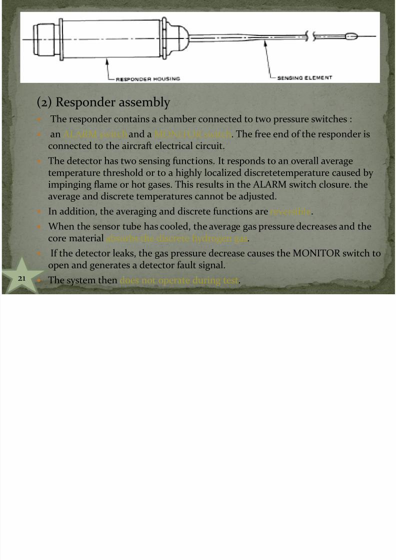
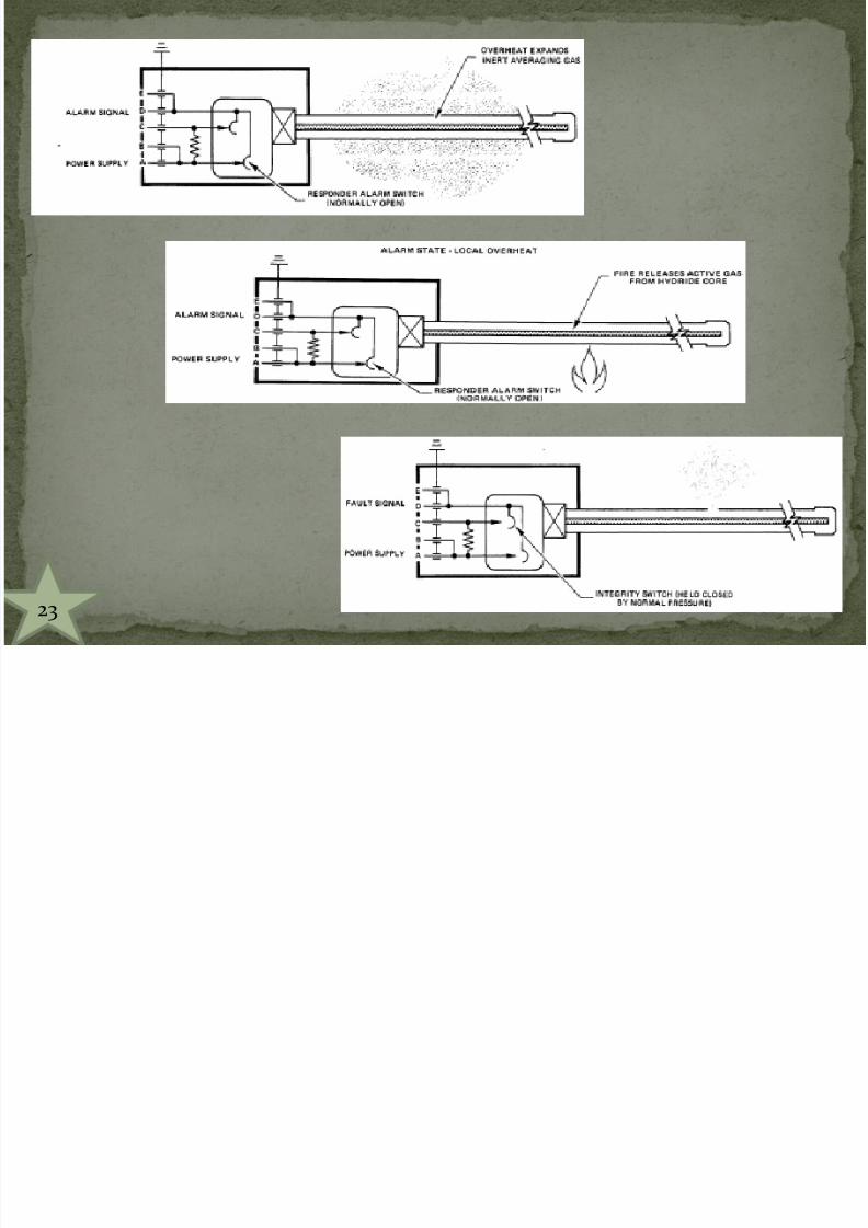
(2) Responder assembly The responder contains a chamber connected to two pressure switches :
an ALARM switch and a MONITOR switch. The free end of the responder isconnected to the aircraft electrical circuit.
The detector has two sensing functions. It responds to an overall averagetemperature threshold or to a highly localized discretetemperature caused by impinging flame or hot gases. This results in the ALARM switch closure. theaverage and discrete temperatures cannot be adjusted.
In addition, the averaging and discrete functions are reversible.
When the sensor tube has cooled, the average gas pressure decreases and thecore material absorbs the discrete hydrogen gas.
If the detector leaks, the gas pressure decrease causes the MONITOR switch toopen and generates a detector fault signal.
The system then does not operate during test.21

7/27/2019 Fire Detection System 1808
http://slidepdf.com/reader/full/fire-detection-system-1808 24/27
22
7/27/2019 Fire Detection System 1808
http://slidepdf.com/reader/full/fire-detection-system-1808 25/27
23

7/27/2019 Fire Detection System 1808
http://slidepdf.com/reader/full/fire-detection-system-1808 26/27
24

7/27/2019 Fire Detection System 1808
http://slidepdf.com/reader/full/fire-detection-system-1808 27/27
THANKS FOR BEING ALERT TO THE PRESENTATION.