fire detection and alarm system
TRANSCRIPT
1
Doc: CED 22(7587)
Draft Indian Standard (Not to be reproduced without the permission of BIS or used as an Indian Standard)
SELECTION, INSTALLATION AND MAINTENCE OF CONTROL AND
INDICATING EQUIPMENTS FOR FIRE DETECTION AND ALARM SYSTEM – CODE OF PRACTICE
_____________________________________________________________ Fire Fighting Last Date for Comments Sectional Committee, CED 22 15 06 2008
1 FOREWORD
1.1 In Fire Alarm systems, Control and Indicating equipment (C and I) are the backbone of the entire network and performs three important functions, namely:
a) Continuous and automatic monitoring and control of circuits external to the equipment (such as fire detection and fire alarm device circuits) and also supply of power to these circuits
b) Indication of fire signals, fault signals and their location
c) Manual control to facilitate actions such as testing, disablement of devices, triggering of fire signals, silencing of audible fire warning and resetting the system after a fire signal.
1.2 As these facilities are required by different people at different times all these facilities need not always be provided at a single location. For example according to the premises, indication of faults might be required by an engineering personnel, who might not require detailed information on fire signals whereas accurate information on the location of a fire is essential to the safety/security personnel, who might need in specific information about system fault(s).
1.3 In small and simple systems the control indicating and power supply equipment for the system normally is housed within a single enclosure. In large and complex premises, the main control equipment circuitry might be installed at one location, power supplies might be distributed around the building, while main indicating equipment incorporating certain basic controls is installed at another location, such as near a main entrance to the building and lastly repeat indicating equipment (with or without control) may be installed at other locations (such as Security or control rooms).
1.4 Since premises vary in size, complexity and fire strategy, it is essential that the nature and location of manual controls and all indicating equipment, in particular, is suitable for the fire and evacuation procedure that are to be adopted and for the person that will use the system, including security or safety staff and fire-fighter attending a fire. Location of control circuitry and power supplies will more likely to be determined by engineering considerations and the preference of the personnel who are going to use the system.

2
For the purpose of deciding whether a particular requirement of this standard is complied with, the final value observed or calculated, expressing the result of a test or analysis, shall be rounded off in accordance with IS 2 :1960 `Rules for rounding off numerical values (revised)’. The number of significant places retained in the rounded off value should be the same as that of specified value in this standard.

3
Doc: CED 22(7587)
Draft Indian Standard (Not to be reproduced without the permission of BIS or used as an Indian Standard)
SELECTION, INSTALLATION AND MAINTENCE OF CONTROL AND
INDICATING EQUIPMENTS FOR FIRE DETECTION AND ALARM SYSTEM – CODE OF PRACTICE
1 SCOPE
1.1 This standard covers planning, design, maintenance and performance criteria for Control and Indicating equipments for fire detection and alarm systems.
1.3 This standard covers minimum level of protection. Nothing in this standard prevents to install systems designed for higher degree of protection, for special risks, etc.
2 REFERENCES
The standards listed at Annex A contain provisions which through reference in this text, constitute provisions of this standard. At the time of publication, the editions indicated were valid. All standards are subject to revision, and parties to agreements based on this standard are encouraged to investigate the possibility of applying the most recent editions of the standards indicated at Annex A.
3 LOCATION OF CONTROL AND INDICATING EQUIPMENT
3.1. The following requirements shall be followed by the user and installers before locating control and indicating equipment.
a) Indicating equipment, in conjunction with suitable manual control facilities, shall be located at an appropriate location for both safety staff and fire-fighters responding to a fire signal.
b) The location shall normally comprise an area on the ground floor close to the entrance to the building likely to be used by the fire fighters, or a suitably located, continuously manned control room from which at least initial control of any fire incident, by safety staff and/or the fire fighters, will be implemented.
c) In complex premises, there shall be consultation between the user, installer and the fire fighters, regarding the location of all control and indicating equipment and the facilities provided.
d) Where there are multiple entrances to a complex building, there shall also be consultation with the external fire brigade regarding the possible need for repeat control and/or indicating equipment.

4
e) In buildings which are not continuously occupied, location of indicating
equipment in a location that will be visible to the fire brigade from outside the building can be of benefit, particularly if there is a facility for transmission of alarms to an alarm receiving centre.
3.2 All control indicating and power supply equipment that is likely to need routine attention for maintenance shall be located in readily accessible locations that facilitate safe maintenance work.
3.3 The surrounding ambient illumination level in the vicinity of all control and indicating equipment shall be such that visual indications can be clearly seen, controls easily operated and any instructions or legends can be easily read. Where this is impracticable, suitable illumination backed up by an emergency source shall be made available.
3.4 The surrounding ambient noise level in the vicinity of all control and indicating equipment shall not be such as to prevent audible indications (such as the fault warning sounder) from being heard.
3.5 The fire alarm control and indicating equipment, power supply equipment for the control and indicating equipment and other essential control facilities shall be located in safe areas, so that the equipment is unlikely to be involved in a fire before adequate warning has been given.
3.6 It is preferable to provide detection system for the enclosure where C and I equipment is installed though it is compulsory if installed in a part of the protected building.
3.7 On or adjacent to indicating equipment there shall be a diagrammatic representation of the building showing at least the building entrance, the main circulation area and the division into zones. Where the division into zones is not provided, a correctly orientated plan of the premises shall be displayed.
NOTE See also clause 6 for additional requirements.
4 GUIDELINES FOR NETWORKED FIRE ALARM SYSTEMS
a) The functions of the control and indicating equipment are not centralized in one location or panel, but distributed amongst a number of Sub panels located remotely from each other. These panels are than inter-connected by a network which usually serves as a data highway. Some sub panels may simply act as ‘data gathering’ panels and provide no indications. Others may be fully functional control and indicating panels. Control and indicating panels configured so as to “stand alone” and continue to operate normally in the event of a failure of the communications links between sub panels.
b) Networked system is usually installed in the following circumstances i) Where the fire alarm system is large and beyond the capacity of single control and indicating equipment and ii) Where there is a need for centralized monitoring and/or control of a number of fire alarm systems in different buildings in the same vicinity (e.g. on the same site).

5
c) The effect of the communication link and the implications for fire alarm
operation will depend on the configuration of the networking system, the type of network and whether or not the network forms part of the critical signal path.
d) Ring or loop network are more resilient to communities failures than redial type network, peer to peer network with a central processor controlling panel to panel communications.
e) If all Sub –panel can function as “stand alone” fire alarm system and do not depend on the network to facilities primary alarm functions (e.g sounding the alarm initiating other activities), a communications failure will have no significant effect and the network can be considered as an ancillary circuit.
5 POWER SUPPLIES
5.1 General
a) Power supply for the fire alarm system will normally be derived from the low voltage mains supply needs to be reliable and capable for supplying the largest load that can be placed on it under normal, fire and fault conditions.
b) The design of the main supply to the system needs to be such that it is unlikely to be affected by faults on other circuits or equipment, or by isolation of supplies in the building for maintenance or economy in consumption of electricity.
c) The main supply shall need to be backed up by a standby supply that is able to support the system while the main supply is restored or fault in the mains supply is corrected. The standby supply also needs to be reliable, and transfer between the two supplies shall not affect the operation of the system.
d) Failure of the main supply may occur when the premises are unoccupied, the system might be inoperative on reoccupation. It is important that the presence of a power supply to the system is indicated by a visual indicator at the indicating equipment to enable total power failure to be identified by the personnel.
e) There will be a need to set some practical limit on the duration of standby batteries. However when the premises are not occupied for longer durations, the limit recommended in this standard could be insufficient to cater for the longest periods for which premises might be unattended. The user will need to consider this aspect and arrange frequent check on the batteries or consider the need for standby batteries with a longer duration.
f) If the premises are provided with emergency supply through a diesel generator or a captive power plant and if the process in the risk is continuous, then the capacity of the standby batteries may be reduced provided the circuits served by the generator include that of the alarm system.

6
g) In some complex buildings, such as shopping centre, additional indicating
equipment, such as color graphics terminals, not essentials for compliance with this standard, may be provided to assist the user in the monitoring and control of fire incidents. Stand-by supply shall take care of this equipment also.
NOTE Detailed requirements for the above are listed in various clauses below.
5.2 Requirements
The system shall derive its power from either:
a) The mains electricity supply single phase (normal supply), or the standby power supply that shall be immediately available in the event of failure of normal supply and shall be automatically connected (automatic switch-over) so as to maintain the equipment in ready condition of taking the maximum load. The standby shall be derived mostly from exclusive secondary batteries where captive power generation (like automatically started generation, continuously running generation) is readily and certainly available, such as in process plants, industrial complexes and other occupancies, a standby can be derived from there.
b) The C and I equipment shall be connected to the mains via a switch-fuse or MCCB reserved solely for the purpose, its cover being painted red and labeled ‘FIRE ALARM’’ DO NOT SWITCH OFF’. Switch-fuse shall be contained in a securely closed box and the condition of ‘main-on’ shall be indicated by a new lamp. The voltage and ampere ratings shall be compatible with the requirements of various parts of the system and power capacity of the power supplies shall meet the maximum load likely to be placed on the system.
Where the user requires isolating the building during closed hours, a separate supply shall be provided for the fire alarm system that shall not normally be isolating during closed hours.
c) The minimum capacity of the normal mains supply shall be calculated so as to meet the total power consumption of the entire system in quiescent condition plus that of all the sounders and 25 percent zones in alarm condition.
d) Main connection to the system shall be arranged such that the mains supply to the system (which is through exclusive switch-fuse) is not interrupted as a result of switching off mains power to premises/other services. Provisions made for normal and standby power supply shall be such that the switch-over from one supply to another is automatic and each is capable of supplying the largest load to be placed on them under normal, fire and fault conditions. Further, the power supply for the fire alarm system shall be totally dedicated and shall not be connected to other loads.
e) The standby power supply shall be capable of maintaining the system in normal operation for a period of not less than 48 h after the failure of normal mains supply after which sufficient capacity would remain to provide full load operation for at least 30 minutes. The full load would be defined as that

7
caused by the operation of all the alarm sounders operating simultaneously, operation of a detector in at least 25 percent of zones (with a minimum of two zones) and the operation of the fault indicator. The operation of trigger devices in further zones shall not result in cancellation of fire alarms existing at that time.
NOTE
Where failure of normal mains supply is not likely to be made good within 24 h
due to long unattended/unoccupied periods, the system inspection frequency need to be arranged at intervals such that in the event of normal mains supply failure, at least 24 h standby capacity remains at the time of next inspection.
f) Standby power supply derived from exclusive back-up batteries shall have provision of automatic charging and automatic load switch-over whenever normal mains supply fails. It shall be ensured that charging conditions are matched to the system. The rate of battery charging shall be such that, having discharged to its final voltage, the battery can comply with the recommendations of 5.2 (e) after a charging period of 24 hours.
g) The external batteries shall be properly mounted. The best practice shall be to mount them on a metal stand at a well ventilated location.
h) Every isolator, switch and protective device that is capable of disconnecting the mains supply to the fire alarm system, shall be situated in a position inaccessible to antiauthority persons or be protected against unauthorized operations by persons without a special tool.
i) The voltage of the batteries shall be monitored and low voltage indicated on C and I equipment.
j) Capacity of the battery shall be as per calculations shown in Annex ‘B‘.
k) Where distributed power supplies for fire alarm system to power sounders, beam detectors etc. are installed, It shall be mandatory that the entire system be powered from the C and I Panel power/back up and the same shall be monitored.
6 CABLES AND THEIR INSTALLATIONS AND CIRCUITS
6.1 General
a) The components of most fire alarm systems are connected by cables and wiring and hence, cables are most important link between fire detection devices and the control centre. It is essential that the cables used for interconnection of devices and the control centre remain operational and maintain circuit integrity for adequate duration with inherent capability to resist direct exposure to fire. Loop shall be of Class A wiring. Class A wiring will be return loop. Tapping may be used from the loop as Class B wiring.
NOTE Refer Fig 1 for wiring details.

8

9

10
b) It is essential that all interconnections operate correctly at the time of a fire. This is particularly important in the case of cables that link control and indicating equipment to manual call points, automatic fire detectors and fire alarm devices, and that transmit signals to an alarm receiving centre.
c) It is not normally possible to predict, with any accuracy, those areas of a building in which fire can or cannot occur. At the design stage, the exact route that cables will follow may also be unknown. Therefore to ensure that cables used remain operational for an adequate duration, cables, with an inherent ability to resist attack by fire, need to be used throughout.
d) The integrity of the mains supply to the system is also regarded as essential, even though the system has a standby supply. Accordingly, mains supply circuits need to be adequately protected against the effects of fire.
e) The probability of disablement of any part of the fire alarm system as a result of mechanical damage to cables can be reduced by the use of sufficiently robust cables, careful selection of cable routes and by the provision of protection against mechanical damage in areas where cables are susceptible to mechanical damage. Monitoring of circuits does not ensure that cable faults will not occur, but is essential to minimize the time between occurrence and identification (and hence repair) of the fault. Monitoring of circuits and protection of cables against damage are, therefore, complementary precautions, rather than alternatives.
f) It is the responsibility of the designer to ensure that the electrical characteristics of the cables, including current carrying capacity and voltage drop are suitable for the system. The choice of cable and routes selected shall need to take into account the need to avoid electromagnetic interference from other cables and source of electromagnetic radiation, particularly in the case of the system in which cables are used to be combative with the characteristics of the data transmission for example speed and waveform and remain so far an adequate length of time during the relevant exposure to fire for category of cable.
g) The circuit of fire alarm systems shall need to be segregated from the cable of the other circuit to minimize any potential for other circuit to cause malfunction of the fire alarm system arising from
breakdown of cable insulation of other circuit and /or fire alarm circuit
a fire caused by a fault on another circuit
electromagnetic interference to any fire alarm circuit as a result of the proximately of another circuit
damage resulting from the need for other circuit to be installed in, or removed from, ducts or trucking containing a fire alarm circuit .
h) In order to facilitate identification of fire alarm circuit, cable shall preferably be red in color, unless another form of colour coding is appropriate. By this means, the possible need for appropriate segregation can be identified, and there will be less likelihood of inadvertent manual interference with the circuit of fire alarm systems.
11
6.2 Cables
6.2.1 The electrical characteristics of all cable, such as voltage drop, current carrying capacity, impedance and, where appropriate, ability to transmit data, shall be suitable for the system.
The cable specification for fire alarm system is as follows:
a) Armoured or unarmoured FRLS cables of minimum 2 x 1.5 mm2 ATC cables for conventional fire alarm and multistrand,twisted pair shielded cables for addressable fire alarm system
b) PVC insulated copper conductor cables conforming to IS 694 having minimum 1.5 mm2 cross-sectional area, if stranded at least 0.5 mm2 cross-section shall be used.
c) Rubber insulated braided cables conforming to IS 9968 (Part I).
d) Armoured PVC / rubber insulated cables conforming to IS 1554 (Part 1)
e) Mineral Insulated (MI) cables with overall LSF (Low Smoke and Fumes)
NOTE It is strongly recommended to use cables mentioned under item ‘e’ above for certain specific occupancies like Oil and Hydrocarbon Industries (high hazard, high fire potential), Airports (high hazard and also large public presence), Jetty (high hazard, high fire potential), Power Plants (critical for use), Metro Railways (underground and large public presence, life safety), and where huge public gathering is anticipated like Shopping malls, Multiplex and large assembly halls (life safety) etc. where either the fire load is high or the intolerance of downtime for the occupancy or life safety is foremost.
6.2.2 The cables used shall be exclusively for fire detection system. The multi-core cables shall not be shared for other low voltage or high voltage circuits.
6.2.3 Cables/wiring shall be laid down in metallic/rigid PVC conduits. PVC Conduits shall be used only in concealed spaces.
6.2.4 Cables connected to detectors shall be given ‘S’ loop on both the sides of the detectors which shall be properly clamped to the ceiling. Loop shall also be left where cables connect sounders, panels, dampers, etc. Appropriate glands shall be provided where the cable enters the junction box.
6.2.5 All the cables and wires shall be tagged for proper identification. Wires shall be identified by ferrules at junction and cables by colour bands at every 3 m distance.
6.2.6 When connecting different buildings etc. overhead lines for fire alarm system shall not be used. They shall be laid underground according to IS 1255.’
12
6.3 Conduit wiring
The requirements given below shall be followed:
a) The conduits shall not be choked with cables. There shall be sufficient space inside the conduit even after the cable is pulled. The minimum size of the conduit shall be 25 mm.
b) S-runs of conduits which shall be spaced at not more than 4.25 m between draw boxes, shall not deflect from the straight by an angle more than 15º. B-runs of conduits shall not deflect from the straight by more than 15º. Conduits shall be kept at a minimum of 100 mm from the pipes of other non-electrical services.
c) Wiring for short extensions to outlets in hung ceiling or to vibrating equipments, motors etc., shall be installed in flexible conduits. No flexible extension shall exceed 1.2 m in length.
d) Cables and Conduits run on surfaces shall be supported on galvanised steel 6 mm thick saddles and clamps which in turn are properly screwed to the wall or ceiling. Saddles shall be at intervals of not more than 500 mm. Fixing screws shall be with round or cheese head and of cadmium plated brass.
e) Exposed conduits shall be neatly run parallel or at right angles to the walls of the building. Unseemly conduit bends and offsets shall be avoided by using fabricated galvanised steel junction/pull through boxes for better appearances.
f) No cross-over of conduits shall be allowed unless it is necessary and entire conduit installation shall be clean and neat in appearance. Conduits embedded into the walls shall be fixed by means of staples at not more than 500 mm intervals. Chases in the walls shall be neatly made and refilled after laying the conduit.
g) Conduits buried in concrete structure shall be put in position and securely fastened to the reinforcement before the concrete is poured. Proper care shall be taken to ensure that the conduits are neither dislocated nor choked at the time of pouring the concrete.
h) Suitable galvanised steel fish wires of not less than 0.63 mm dia shall be drawn in all conduits before they are embedded. Where conduit passes through expansion joints in the building, adequate expansion fittings shall be used to take care of any relative movement.
i) Inspection boxes shall be provided for periodical inspection to facilitate withdrawal and removal of wires. Such inspection boxes shall be flush with the wall or ceiling in the case of concealed conduits. Inspection boxes shall be spaced at not more than 12 meters apart or two 90 degree solid bends or equal.
j) All junction and pull boxes shall be covered by 6 mm clear plate truly cut and fixed with cadmium plated brass screws. These junction boxes shall form part
13
of point wiring or conduit wiring as the case may be including the cost of removing the cover for painting and refixing.
k) Conduits shall be free from sharp edges and burs and the threading free from grease or oil. The entire system of conduits must be completely installed and rendered electrically continuous before the conductors are pulled in.
l) Conduits shall terminate in junction boxes of not less than 32 mm deep and the termination shall be rigid with check nuts and a smooth bushing. No wires shall be exposed in any part of the installation.
m) Conduits and Cables shall be laid by skilled and experienced workmen. Care shall be taken while laying cables to avoid kinks. At all the changes in directions (vertical and horizontal planes) the cables shall be bent smooth with a radius as recommended by the manufacturers.
n) No joints shall be allowed between two points. The sleeve at joints shall be shaved off like a pencil and shall not be cut square to avoid cutting of conductors.
7 CONTROL CENTRE (FOR HOUSING C and I EQUIPMENT)
a) In high rise buildings and special buildings, a control centre of an area of 15 m2 to 20 m2 shall be provided where the control and indicating equipment, power supply units and other fire protection ancillary panels could be installed. This shall preferably be on ground floor (floor one) and manned 24 h.
b) The Control centre room shall have attached WC bath, drinking water facilities and appropriate tables, chairs, record racks, etc.
c) The control centre room shall have emergency lighting system.
d) The control centre room shall have intercom and direct telephone facilities. Where possible, a direct hotline or any other means of communication to local fire brigade shall be provided.
e) The control centre room shall have mimic panel of the premises protected and details of all the fire protection systems. Fire orders shall be prominently displayed.
f) Control centre in air conditioned premises shall be segregated from the rest of the buildings by fire walls and provided with an independent A/C system. If ducts are common, the entry/exit points of ducts through the walls shall be provided with automatic damper units. Status of these dampers shall also be displayed in the mimic panel.
8 CONTROL AND INDICATING EQUIPMENT (COMPONENTS)
8.1 SECTOR / ZONE PANELS AND C and I EQUIPMENT
a) The sector/zone panel shall be installed on individual sector / zone of the building and shall conform to the requirements given in Annex C.

14
b) The C and I equipment and other control panel shall be wall mounting/floor
standing type and shall be made of mild steel sheet conforming to IS 513. The minimum thickness of sheet shall be 1.6 mm. The colour shall be fire red (Shade no.536 of IS 5).
c) Electronic/Electric circuit shall have relay conforming to the relevant Indian Standard.
d) Each sector / zone indicator, indicating fire shall consist of two LED / filament bulbs conforming to relevant Indian Standards connected in parallel. In case of fault indicators, only one LED / filament bulb shall be used – open and short circuit separately. Fire warning indicator shall be clearly labelled and coloured red while fault warning indicator shall be clearly labeled and coloured amber.
e) The sector panels shall have the power capacity to be connected to all the zones in the sector. In addition, it shall have facility for connections to external sounders.
f) If required, the panel shall have additional capacity to operate auxiliary equipment like fire dampers, fire closers, ventilation and/or pressurizing fans, emergency light, smoke exhausters, etc. Failure rate of power at the local sector panel shall be indicated in the main control room.
8.2 Fire Alarm / External Fire Alarm Sounders
a) A number of external fire alarm sounders are generally required for protective premises. The number and distribution of these alarms in the premises shall be such that the sound level / audibility requirements are met with a view to alert the occupants and initiate fire fighting actions with the least delay.
b) The grouping of external fire alarm sounders can be done in either of the following way. The grouping scheme shall be reflected in fire instructions issued for the use of the occupants.
c) Sounding of alarms can be so arranged that any alarm operated all the sounders throughout the premises. This grouping is particularly suitable for smaller premises.
d) Sounding of alarms can be so arranged that the alarms sound initially in the sector of fire origin or in this zone and on its adjoining areas, or in this zone and in specially selected areas of high flammability or difficult egress.
8.3 Silencing
The operation of silencing switch either for general fire alarm sounders or for signal controlling internal audio alarm of C and I equipment shall cause an audible signal to be given in or near the C and I equipment. This audible signal which may be the same as that for fault warning, is intended to act as a reminder that the silencing switch has been operated and shall give a distinctive sound

15
different from that of any other alarm sounder (external or internal to C and I equipment).
NOTE – The requirement given here are not necessary in systems where automatic re-set is provided.
8.4 Visual Alarm Signals
In general, visual signals shall only be used to supplement audible alarms. A defect in visual alarm shall not cause a defect in audible alarm or vice versa. Only in special cases where audible alarm is ineffective, such as even the occupants are deaf, immobile, etc., visual alarms can be used in lieu of external alarm sounders.
8.5 Stages of General Fire Alarms
General fire alarm system though external sounders can be provided in either of the following ways:
a) Single Stage Continuous Alarm – in this scheme, a continuous alarm (evacuation alarm or signal) sounds in the sector / zone of fire and also on the C and I equipment with a provision on C and I equipment to sound continuous general fire alarm throughout the protected premises. This is normally done, particularly in smaller premises, sparely populated premises or storage premises.
b) Two-Stage General Alarms - In this scheme, two-stage alarm is provided in which a continuous evacuation alarm is immediately given in sector/zone of fire or in a restricted area, together with intermittent ‘alert’ signal in other parts and on C and I equipment. The provision shall be made at C and I equipment for changing the ‘alert’ signal to ‘evacuate’ signal in any area, either manually or after a pre-determined period, automatically. In deciding the time delay between ‘alert’ and ‘general evacuation’, consideration shall be given to the communications that may be needed to control the evacuation.
c) The ‘evacuation’ signal shall be continuous and intermittent ‘alert’ signal shall have ‘ ON’ and ‘OFF’ periods of 1.0 ± 0.5 s each.
d) In large installations, extensive and high rise buildings, two-stage alarm scheme may be more desirable to evacuate first the sector/zone where fire exists, other high risk areas or restricted areas and simultaneously ‘alert’ other areas.
8.6 Special System
a) Here the alarm sounds only in the control centre of the C and I equipment and may also have public address facility to alert personnel who are mobile within or in the vicinity of the building.
b) Depending on the choice of the system, C and I equipments shall have necessary controls. Where two stage alarm is chosen, zonal/sectors panels
16
and C and I equipment are needed and in case of single stage zonal/ sector panel are not needed.
c) The system may also adopt any of the cabling scheme, that is connecting zones/sectors directly to the C and I equipment or through zone/sector control panels.
d) The audible and visual alarm state shall be maintained by the sector/zonal control panels ad control panel of C and I equipment without a continued signal from fire detector. The sound characteristics of the alarm shall be similar throughout the protected premises.
8.7 Fire Alarm Intimation
The operation of fire detector/manual call point shall initiate transmission of signal(s) resulting in :
a) an audible signal on the C and I equipment (internal audio alarm C and I equipment)
b) a visual signal in the C and I equipment, c) at least one external alarm sounder, d) a visible indication for each sector / zone in which a detector / MCP
operations, and e) audible signal (alert) on sector / zonal panel concerned where sector/zonal
panels have been provided.
In case of two stage alarm systems, if the alarm in the first instance is not acknowledged on C and I equipments, preferably within 60 s, a general evacuate alarm shall sound on all the floors.
8.8 Silencing of Fire Alarm
a) The audible alarm(s) as specified in (a) and (b) of 8.7 shall continue to operate until silenced manually. The alarm shall not be silenced automatically. The operation of the silencing switch shall automatically result in an audible/visual signal being given at C and I equipment until the fire alarm is reset.
NOTE – Provision in this clause are not necessary in case of automatic reset system.
b) The equipment shall be so designed that following the silencing of alarm sounders, in the event of subsequent operation of detector MCP in any other zone, further fire alarm as specified in 8.7(a) and (b) shall be given.
c) Any fault signal as specified in 8.9 which the C and I equipment may be giving shall not prevent a fire alarm being given, if the detector actuates at the same time or subsequently from the other zone.

17
8.9 Fault Signals
An immediate fault warning shall be given by (a) visible indicator (amber) on the sector/zone control panel (where provided), and (b) an audible alarm and visible indicator (amber) on the C and I equipment in the control centre. The audible alarm shall be distinct from the fire alarm.
a) The zonal arrangement in the panel shall be modular and mere replacement of fault module/rely plug in components shall put the alarm system back in operation.
b) Fault warning shall be given at C and I equipment in the event of the following occurrences:
I. Failure or disconnection of normal power supply., II. Failure or disconnection of standby power supply,
III. Failure or disconnection of battery charging equipment, IV. Short-circuit or disconnection of the leads to trigger devices unless the
fault conditions reproduces the effect of the operation of a triggered device,
V. Removal of any triggered device of the plug in type or disconnection from its transmitter or power supply,
VI. Short-circuit or disconnection of any of the leads to alarm sounders external to the control and indicating equipment but if the alarm sounders are connected by a ring circuit, disconnection need not be immediately indicated but shall be capable of being detected by the routine test procedure,
VII. Rupture or disconnection of any fuse on the operation of any protective devices that would prevent a fire alarm being given, and
VIII. Failure of a scanning device to interrogate the detector or zones at the correct time intervals or failure of any monitoring or interrogating system within the control equipment, such as to prevent an alarm being given.
IX. A facility may also be provided for sending fault signal to remote centre.
c) It is desirable to have distinct earth fault indication of the zone wiring.
d) A facility shall be provided for deliberate isolation of zones/sectors. This facility shall be inside the panel not easily accessible to people. Whenever isolation is used, this shall be given visible indication.
e) Circuits and mechanical design of the panel shall be such that the operation of one indicator does not prevent the operation of the other indicators and the alarm is not inhibited by any defect/failure in the indicator.
f) Each fire/fault indicator shall be clearly labeled with the zone address on a metal label from which the call originates.
g) ‘System on’ and ‘Standby on’ indicators shall be provided. Where system test key/switch is lockable, indicator shall be provided.
h) Test facilities, shall be provided to test alarm circuit sounder, indicator etc.

18
i) The following shall be provided :
1. Acknowledge button; 2. Where required, alarm cancel indicator, 3. Isolation / reset facility ; and 4. Related fuses / protective devices
j) Sector /Zonal control panel shall be provided with voltages appropriate to the rating of the interconnected detectors. The voltage drop in the cable risers shall be taken into account.
8.10 Fire Alarm (Sounder)
a) Depending on the floor area and its layout, external audible fire alarm sounders shall be provided to give the required sound level with a minimum of a pair of sounders in parallel. The number of fire sounders shall be sufficient to produce the sound levels as specified in Annex D and measured as per IS 9779.
b) The circuit feeding power from control panel to these fire alarm devices shall be a ring circuit. If a ring circuit is not provided, design provision to give a fault signal on C and I equipment in the event of short circuit or disconnection shall be made.
8.11 Accessories and Controls
a) Control and indicating equipment shall be installed in the control room on ground floor. In the case of industrial premises, separate process control rooms are provided and shall be of the wall mounting/desk/floor standing type.
b) The manual controls for switching off/on, main/standby power shall not be accessible to outsiders.
c) All manual controls shall be clearly labeled to indicate the mode of operation and their functions (metal label to be used).
d) The C and I equipment shall have electronic/electrical relays conforming to relevant Indian Standards and shall have the following facilities:
I. A pair of red LED/bulb to indicate origin of fire and an amber LED/bulb to indicate the origin of fault;
II. A sounder with distinct audible sounds for fire and fault alarm;
III. Audible signal acknowledge/silence button and lamp/LED to indicate its operation, whenever necessary;
IV. Voltmeter and ammeter shall be provided on main dc power circuit;
19
V. ‘Systems on’ standby on indicators, test key/button operation indicator
and facility to isolate zonal/sector/ main control panel from the rest of the system;
VI. Where sector panel is isolated, its signal shall come on the main control panel and where zonal panel is isolated the signal shall come on the sector panel;
VII. Failure of any indicator circuit shall not prevent the fire alarm from sounding, nor acknowledgement/silencing of the alarm from one zone shall prevent another alarm coming from the other zone on the same sector;
VIII. Switch to actuate alarms from C and I equipment to one or more sectors/zones;
IX. Test facility to check fire alarm/fault circuit, indicators; and
X. The facility for indicators to acknowledge the operation of the ancillary system. (One colour code shall be associated with one ancillary service and one or more indicator per zone.)
NOTE – In high rise/special building like educational, institutional, assembly, business, mercantile and hotels, a handset/two-way speaker with relevant indication switches shall be provided for voice communication with different floors when the circuit is actuated by inserting the handset in manual call point sockets (This is not a part of the fire alarm system).
e) All zonal/sector control panels and control and indicating equipment shall be provided with proper earthing.
9 INSTRUCTION MANUAL
a) The record drawings and operating instructions shall be supplied by the installers on completion of the installation. Drawings shall clearly indicate the position of various items of the equipment, junction boxes, sizes and routes of all cables and wires and such other relevant details for maintenance and record purposes. If so desired by the user, circuit diagrams of the fire alarm system and its components shall also be supplied. These drawings and operating instructions shall be kept up-to-date and be available for convenient reference and shall be located in the control room.
b) The installer shall supply the user with a log book. The log book shall be maintained for recording details, including causes of all the alarms ( genuine, practice, test or false), faults, service tests and routine inspections, servicing / repairs, etc, as and when done. Periods of disconnection/ inoperation shall also be shown.

20
10 INSPECTION, TESTING AND MAINTENACE
10.1 General
Even a well designed and properly installed automatic fire alarm system may not be able to render reliable and trouble-free service unless high standard of maintenance and supervision are ensured during the entire service period of the system. Regular inspections and scheduled preventive maintenance are critical and shall include all the components of the system.
10.2 Initial Installation Inspection Tests
10.2.1 After installation, a visual inspection of all the detectors shall be made to make sure that they are properly sited. Each detector shall be inspected to ensure that it is properly mounted and connected.
10.2.2 Restorable heat detectors and restorable elements of combination detectors shall be tested by a heat source, such as a hair dryer, or a shielded heat lamp until it responds, making sure that the sensing element is not damaged. After each heat test, the detector shall be reset. Precautions shall be taken to avoid damage of the non-restorable fixed temperature element of a combination rate of rise/fixed temperature detector.
10.2.3 Non-resettable fixed temperature heat detectors which are not to be heat-tested shall be tested mechanically or electrically for fire alarm function.
10.2.4 Heat detectors with replaceable fusible alloy element shall be tested first by removing the element to see whether contact operate properly and then re-inserting them in proper position.
10.2.5 In periodic testing, heat detectors shall be visually examined for damage or other conditions (such as heavy coats of paints, etc) likely to interface with the correct operation.
10.2.6 Each smoke detector shall be tested to initiate an alarm at its installed location with smoke or other approved aerosol which demonstrates that the smoke can enter the chamber and initiate an alarm.
10.2.7 In order to ensure that each smoke detector is within its sensitivity range, it shall be tested using either :
a) a calibrated test method, or b) a manufacturer’s / supplier’s approved calibrated sensitivity test instrument, or c) approved control equipment arranged for the purpose, or d) other approved calibrated sensitivity rest method.
10.2.7.1 Detectors found to have sensitivity outside the approved range shall be replaced.
NOTE - Detector sensitivity cannot be tested or measured using any spray / smoke producing device that administers an unmeasured concentration of aerosol/smoke into the detector.

21
10.2.8 Other types of detectors like Flame detectors, Spark/Ember detectors, Aspirating type smoke detectors etc. shall be tested for sensitivity in accordance with the recommendations of the manufacturers and/or the Standards according to which they are made.
10.3 Servicing / Periodical Maintenance
10.3.1 To ensure that regular and reliable servicing/maintenance of the systems and its components is carried out, any of the following methods shall be adopted :
a) Through an agreement / contract with the competent contractor who shall attend to the maintenance/repair, when necessary, promptly.
b) Where no such service contract can be entered into for any reason, atleast one qualified employee of the user with suitable experience of electrical equipment shall undergo special training to deal with all aspects of basic servicing and maintenance, including routine sensitivity tests/checks of the detectors, as and when required.
10.3.2 For institutional occupancies, such as hospitals, hotels, old people’s homes, etc, the provision shall include a requirement that an engineer shall be on call at all times and that request over the telephone for emergency service shall be executed promptly, within 24 h. Serving arrangement shall be made immediately on completion of the installation whether the premises are occupied or not. If the premises are not occupied, special precautions shall be taken, if necessary, to protect the system against damage by dampness or other causes.
10.4 Maintenance Schedule
10.4.1 It is the responsibility of the user of the equipment to ensure that proper instructions are obtained from the manufacturer/supplier or installer regarding the routine attention and test procedures.
10.4.2 The routine to be adopted in individual premises may vary with the use of the premises; equipment installed in corrosive or dirty environmental conditions will need to be checked more thoroughly and at more frequent intervals than that in clear and dry situations. Care shall be taken that all equipments are properly reinstated after testing. The occupants of the premises shall be notified of any test of the system that may result in the sounders being operated.
10.4.3 Daily Attention by User
A check shall be made every day to ascertain that :
a) the panel indicates normal operation; if not, that any fault indicated is recorded in the log book and is receiving urgent attention ; and
b) any fault warning recorded the previous day has received attention.
22
10.4.4 Weekly Attention by the User
The following tests shall be made every week to ensure that the system is capable of operating under alarm conditions.
a) Once a week, at least one trigger device or end of line switch on one zone circuit shall be operated to test the ability of the control and indicating equipment to receive a signal and to sound the alarm and operate other warning devices. If there is more than one zone on a system having unmonitored wiring, each unmonitored zone shall be tested each week, but without sounding the alarm more then once. For systems having monitored wiring and upto 13 zones, each zone shall be tested in turn but if there are more than 13 zones, more than one zone may need to be tested in any week so that the interval between tests on one zone does not exceed 13 weeks. It is preferable that each time a particular zone is tested, a different trigger device is used. An entry shall be made in the log book quoting the particular trigger device that has been used to initiate the test. If the operation of the alarm sounders and/or the transmission of the alarm signal has been prevented by disconnection, then a further test shall be carried out to prove the final reinstatement to the sounders, and if permissible, the alarm transmission circuits; and
b) A visual examination of the battery and connection shall be made to ensure that they are in good condition. Action shall be taken to remove any defect, including low electrolyte level.
Any defect noticed shall be recorded in the log book and reported to the responsible person, and action shall be taken to correct it.
10.4.5 Quarterly Inspection and Test by the User
The following check-list and test sequence shall be carried out :
a) Entries in the log book since the previous inspection shall be checked and any necessary action taken.
b) Batteries and their connections shall be examined and tested to ensure that they are in good serviceable condition.
c) Where applicable, secondary batteries shall be examined to ensure that the specific gravity of electrolyte in each cell is correct. Necessary remedial action shall be taken and an appropriate entry made in the log book. Care shall be taken to ensure that hydrometers, vessels, etc, used in the servicing of alkaline secondary cells are not contaminated by acid and vice versa. Contamination of electrolyte can ruin a cell.
d) Primary batteries, including reserves, shall be tested to verify that they are satisfactory for a further period.

23
e) The alarm function of control and indicating equipment shall be checked by
the operation of a trigger device in each zone as described. The operation of alarm sounders and any link to a remote manned centre shall be tested. Ancillary functions of the control panel shall also be tested where practicable. All fault indicators and their circuits shall be checked preferable by simulation of fault conditions. The Control and Indicating equipment shall be visually inspected for signs of moisture ingress and other deterioration.
f) A visual inspection shall be made that structural or occupancy changes have not affected the requirements for the sting of trigger devices (manual call points, smoke detectors and heat detectors). The visual inspection shall also confirm that a clear space of at least 750 mm radius is preserved in all directions below every detector, that the detectors are preferably sited and that all manual call points remain unobstructed and conspicuous.
Any defect shall be recorded in the log book and reported to the responsible person, and action shall be taken to correct it.
10.4.6 Annual Inspection Tests
The following checks and test sequence shall be carried out :
a) The instruction and test routines detailed in 10.4.5(a) to (f).
b) Operation of at least 20 percent of the detectors in an installation shall be checked each year and the selection shall be done in such a way that all the detectors in an installation shall have been checked once in every 5 years.
c) Each detector shall be checked for correct operation using specified test equipment and method, except non-resettable detectors. The checks to be carried out are specified in 10.2.2 to 10.2.5 in respect of heat detectors and, 10.2.6 and 10.2.7 in respect of smoke detectors.
d) Visual inspection shall be made to confirm that all cable fittings and equipment are secure, undamaged and adequately protected.
e) At least once in every three years at the annual inspection, the electrical installation shall be tested. Any defect shall be recorded in log book and suitable remedial action shall be taken.
f) On completion of the annual inspection, the entry shall be made in register in respect of defects found. After the defects are rectified, the entries shall then again be made. And if required, detectors shall be replaced by the new one.
10.5 General Points about Detectors
It is essential (particularly for installations involving life hazard) to ensure specified range of sensitivity of the detectors being installed and that the correct degree of sensitivity is maintained. Users shall satisfy themselves on this point. Sensitivity range shall be checked on equipment as already specified. It is essential to apply frequent sensitivity checks and routine tests as prescribed in the code so that the
24
correct sensitivity levels/degree is maintained during the entire service span of the installation (see 10.2.7)
10.6 Cleaning and Maintenance
Detectors require periodic cleaning to remove dust or dirt that has accumulated. The frequency of cleaning depend upon the type of detector and local ambient conditions. In any case, the interval shall not exceed a period of 3 months. For each detector, the cleaning, checking, operating and sensitivity adjustment shall be attempted only after consulting manufacturer’s instructions. These instructions shall detail methods such as creating vacuum to remove loose dust and insects, and cleaning heavy greasy deposits, following partial disassembly or the cleaning or the washing of detectors to remove contamination, the sensitivity test requirements in accordance with the relevant clauses shall be performed.
10.7 Tests Following an Alarm or Fire
All detectors suspected of exposure to a fire conditions shall be tested in accordance with the provisions contained in this code pertaining to annual inspection tests. In addition, a visual check of the battery charger shall be carried out to ensure perfect serviceability. However, a check shall be made to the extent of damage, if any, to the cables and other components and also the operation of the systems as a whole.
10.8 System Disconnection During Testing
Care shall be taken to minimize the disruption of the normal use of the building by alarm sounding during detector testing. If detectors are removed for testing or servicing, replacement detectors shall be provided.
10.9 Spares
It may not be necessary to keep spares in premises other than covers for manual call point and fuses and other essential spares which shall be worked out based on installation.
25
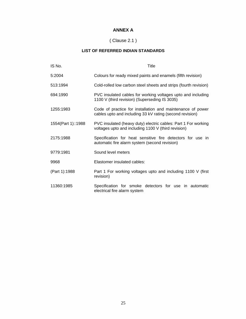
ANNEX A
( Clause 2.1 )
LIST OF REFERRED INDIAN STANDARDS
IS No. Title
5:2004 Colours for ready mixed paints and enamels (fifth revision)
513:1994 Cold-rolled low carbon steel sheets and strips (fourth revision)
694:1990 PVC insulated cables for working voltages upto and including 1100 V (third revision) (Superseding IS 3035)
1255:1983 Code of practice for installation and maintenance of power cables upto and including 33 kV rating (second revision)
1554(Part 1)::1988 PVC insulated (heavy duty) electric cables: Part 1 For working voltages upto and including 1100 V (third revision)
2175:1988 Specification for heat sensitive fire detectors for use in automatic fire alarm system (second revision)
9779:1981 Sound level meters
9968 Elastomer insulated cables:
(Part 1):1988 Part 1 For working voltages upto and including 1100 V (first revision)
11360:1985 Specification for smoke detectors for use in automatic electrical fire alarm system

26
ANNEX B
Method of Calculation of Standbye Battery Capacity For Fire Alarm Panel
1. Valve regulated lead acid Batteries
Apply the following formula:
Cmin = 1.25 (T1 I1+ DI2/2) where
Cmin Minimum capacity of the battery when new at the 20 hrs discharge rate and at 20°C in Ampere-hours
T1 Total Battery Standby period in hours
I1 Total Battery Standby load in Amperes D De-rating Factor I2 Total Battery Alarm Load in Amperes
Note 1: If Cmin/20 will be => than I2, then take D = 1. If Cmin/20 will be is less than I2, then the value of D should be taken as 1.75 or manufacturer’s recommended value
Note 2: In actual practice, Cmin is unlikely to correspond exactly to an available battery capacity and hence the next available capacity size should be used.
2. Other types of Batteries
The minimum capacities should be determined in consultation with the manufacturer and should take into account a) standby load b) alarm load c) any required de-rating to take into account of the higher current drawn in the alarm condition and d) a de-rating factor to take into account of battery ageing during the anticipated life of the battery.
27
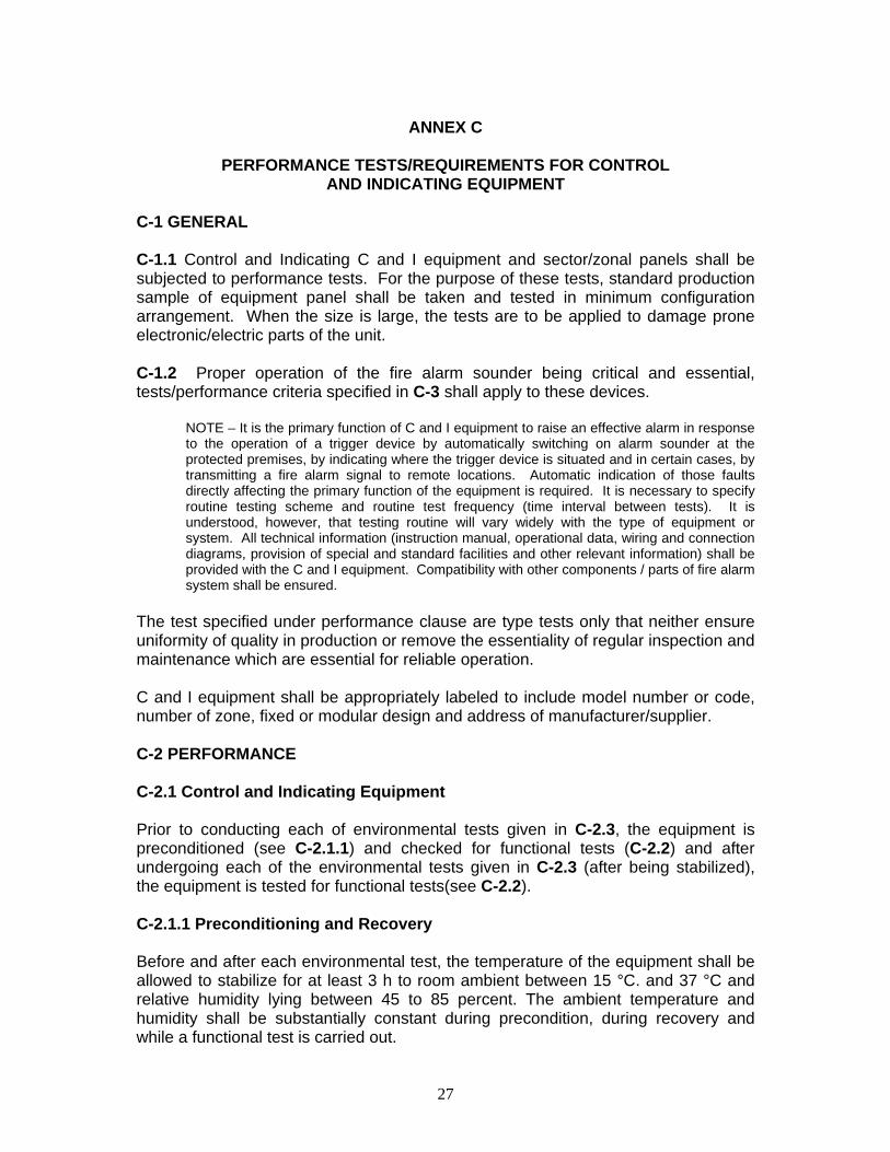
ANNEX C
PERFORMANCE TESTS/REQUIREMENTS FOR CONTROL AND INDICATING EQUIPMENT
C-1 GENERAL
C-1.1 Control and Indicating C and I equipment and sector/zonal panels shall be subjected to performance tests. For the purpose of these tests, standard production sample of equipment panel shall be taken and tested in minimum configuration arrangement. When the size is large, the tests are to be applied to damage prone electronic/electric parts of the unit.
C-1.2 Proper operation of the fire alarm sounder being critical and essential, tests/performance criteria specified in C-3 shall apply to these devices.
NOTE – It is the primary function of C and I equipment to raise an effective alarm in response to the operation of a trigger device by automatically switching on alarm sounder at the protected premises, by indicating where the trigger device is situated and in certain cases, by transmitting a fire alarm signal to remote locations. Automatic indication of those faults directly affecting the primary function of the equipment is required. It is necessary to specify routine testing scheme and routine test frequency (time interval between tests). It is understood, however, that testing routine will vary widely with the type of equipment or system. All technical information (instruction manual, operational data, wiring and connection diagrams, provision of special and standard facilities and other relevant information) shall be provided with the C and I equipment. Compatibility with other components / parts of fire alarm system shall be ensured.
The test specified under performance clause are type tests only that neither ensure uniformity of quality in production or remove the essentiality of regular inspection and maintenance which are essential for reliable operation.
C and I equipment shall be appropriately labeled to include model number or code, number of zone, fixed or modular design and address of manufacturer/supplier.
C-2 PERFORMANCE
C-2.1 Control and Indicating Equipment
Prior to conducting each of environmental tests given in C-2.3, the equipment is preconditioned (see C-2.1.1) and checked for functional tests (C-2.2) and after undergoing each of the environmental tests given in C-2.3 (after being stabilized), the equipment is tested for functional tests(see C-2.2).
C-2.1.1 Preconditioning and Recovery
Before and after each environmental test, the temperature of the equipment shall be allowed to stabilize for at least 3 h to room ambient between 15 °C. and 37 °C and relative humidity lying between 45 to 85 percent. The ambient temperature and humidity shall be substantially constant during precondition, during recovery and while a functional test is carried out.

28
C-2.2 Functional Test
These tests shall consist of the following operation in sequence.
a) Operate momentarily a trigger device (automatic detector/mcp) from any zone to ensure correct functioning;
b) Operate alarm silencing switch to ensure correct functioning;
c) Operate another trigger device (detector/MCP) from another zone to ensure correct functioning of C and I equipment and sector/zonal panel, in case of big/sectored equipment;
d) Operate reset control to ensure correct functioning;
e) Check the audible and visible warnings given on disconnection of normal (mains) power; and
f) Restore the equipment to quiescent condition.
C-2.3 Test Environments
The equipment shall subjected to the following test environments.
C-2.3.1 Dry Heat Environment
The equipment / electronic panels shall be introduced into the chamber/oven which shall be at the ambient temperature of the laboratory (see C-2.1.1) The chamber shall then be adjusted to temperature of 45 ° to 50° and 40 to 45 percent relative humidity. The rate of temperature rise shall not exceed 1°C / min. After the temperature equilibrium in the chamber has been reached, the equipment shall be exposed to these conditions for 16 h continuously.
C-2.3.2 Damp Heat Environment
The equipment/electronic panels shall be introduced into a chamber which shall be maintained at a temperature of 45 ± 3 °C and relative humidity of 90 to 95 percent. The equipment shall be exposed to these conditions for 16 h continuously.
C-2.3.3 Cold Environment
The equipment / electronic panel while being at the ambient temperature of the laboratory, shall be introduced into the chamber, which shall also be at that temperature at the start. The temperature shall then be lowered to 0 ± 5 °C at the rate not exceeding 1 °C/min. The equipment shall be exposed to cold environment for a period of 16 h after the temperature stability has been reached. The equipment shall remain in the chamber during the recovery period ( of 3 h) with cooling off.

29
C-2.3.4 Vibrations
The equipment mounted on vibrating table in its normal operating position and by its normal fastenings shall be subjected to vibrations as given in IS 2175.
C-2.4 Inspection and Performance Requirements
After each environmental test, the equipment shall be opened and inspected for faults consequential to that test. The equipment/panels shall be considered satisfactory if :
a) no damage is revealed during inspection which is a result of the faulty design or workmanship and
b) each operation made during the functional tests specified above cause the equipment/panel to operate normally.
C-2.5 Operational Test
With C and I equipment in its quiescent condition for 20 h, the cumulative effect of the operation of trigger device shall be applied to each zone in succession, the audible alarm being silenced between each operation where this facility is provided. The equipment shall be considered satisfactory if all fire alarms supposed to be initiated by the operation of a trigger device functions normally and no fault warning is given as a result of this test. In successive zone activation process for a control panels having than three zones, heat detectors, smoke detectors and mcps shall be used unless otherwise specified. The following two conditions shall be observed :
a) At least one zone shall be activated by type of trigger device and
b) mcp shall be mounted and operated as intended while heat and smoke detectors shall be mounted (at least once) in hot air tunnel (as per IS 2175) and smoke tunnel (as per IS 11360) respectively and brought into operation by essentially slow build up of temperature and smoke concentration. Rate of rise of temperature shall be 3 °C /min and rate of smoke build up shall be less than 0.2 dB/m as prescribed in the standard for measuring the response of smoke detectors.
C-3 FIRE ALARM SOUNDER
C-3.1 Continuous Normal Operation
The fire alarm sounder shall be able to operate continuously for a period of at least 50 min without damage or malfunction. The sound output (peak value) shall not vary by more than ± 5 dB(A) during this operation.
C-3.2 Sound Level / Characteristics
The sound level (peak value) shall be not less than 65 dB(A) and not more than 120 dB(A) when measured at a distance of 1.5 m (measured in audiometric chamber).

30
C-3.3 Environmental Stresses
Construction and housing of sounder shall be such as to afford protection against fouling by dust and damage by other environmental stresses.
a) Dust – One device shall be exposed to dust test as described in IS 11360.
b) Corrosion – One device shall be suspended in corrosive atmosphere of SO2
as described in IS 2175.
c) Vibrations – One device shall be mounted on vibrating table and shall be subjected to vibrations as per IS 2175.
d) Climatic Conditions – One device shall be exposed to dry heat, damp heat and cold environment as per C-2.3.1 to C-2.3.3 above.
After each environment stress test, device shall be inspected for faults consequential to that test and its sound output measured. Device shall be considered satisfactory if no damage is revealed and operates normally without output variation greater than ± 5dB(A).

31
ANNEX D
Typical Occupational Noise Levels
Location Decibel Level
Business Occupancies 55 Educational Occupancies 45 Industrial occupancies 80 Institutional Occupancies 50 Mercantile Occupancies 40 Mechanical rooms 85 Piers and water surrounded structures 40 Places of Assembly 55 Residential Occupancies 35 Storage Occupancies 30 Thoroughfare and High density urban 7 Thoroughfare and Medium density urban 55 Thoroughfare and rural and suburban 40 Tower occupancies 35 Underground structures and windowless buildings 40 Vehicles and vessels 50 Conferences and meeting rooms 40-45 Exhibition Halls 63-73 Commercial Kitchens 65-75 Boiler areas 75-85 Air conditioning plant 85-90 Cafeterias 68-78 Railway Stations 75-85 Shopping Malls 70-75 Sports halls 70-80

This document was created with Win2PDF available at http://www.win2pdf.com.The unregistered version of Win2PDF is for evaluation or non-commercial use only.This page will not be added after purchasing Win2PDF.