fiq 77* * v/ - defense technical information · pdf filejected to external pressure loading....
TRANSCRIPT

LIBRARY
TECHNICAL REPOPTT SCOTtO* NAVAL POSTGRADUATE SCHQOff MONTERE*, CAUVOUtlA
fiQ 77* * V/
/
/O ^ (T
Prepared for Office of Naval Research
Contract No. N00014-69-A-0200-4048
A li *" t/ UCyVENG^414
FEBRUARY 1974
OPTIMUM DESIGN OF RING STIFFENED CYLINDRICAL SHELLS ,
A.J. BRONOWICKI R.B.NELSON L.P. FELTON
L.A. SCHMIT. JR.
Reproduction in whole or in part is permitted for any purpose of the United States Government.
UCLA • SCHOOL OF ENGINEERING AND APPLIED SCIENCE

TTMri.ASS-nrTF.T1 SECURITY CLASSIFICATION OF THIS PAGE (When Data Entered)
REPORT DOCUMENTATION PAGE READ INSTRUCTIONS BEFORE COMPLETING FORM
1. REPORT NUMBER 2. GOVT ACCESSION NO 3. RECIPIENT'S CATALOG NUMBER
4. TITLE (and Subtitle)
OPTIMUM DESIGN OF RING STIFFENED CYLINDRICAL SHELLS
5. TYPE OF REPORT & PERIOD COVERED
6. PERFORMING ORG. REPORT NUMBER
UCLA-ENG-7414 7. AUTHORfsj
Allen J. Bronowicki Richard B. Nelson Lewis P. Felton
Lucien A. Schmit, Jr. 8 CONTRACT OR GRANT NUMBERfsJ
Contract No.
N00014-69-A-0200-4048 9. PERFORMING ORGANIZATION NAME AND ADDRESS
Mechanics and Structures Department j School of Engineering and Applied Science j University of California, Los Angeles, Cal. 90024
T'lO. PROGRAM ELEMENT. PROJECT. TASK ! AREA A WORK UNIT NUMBERS
II. CONTROLLING OFFICE NAME AND ADDRESS
Procuring Contracting Officer Office of Naval Research Department of the Navy. Arlington, Va.
12. REPORT DATE
February 1974
22217 13. NUMBTR OF PAGES
_22 U. MONITORING AGENCY NAME ft ADDRESS«-'/ dlttarent from Controlling Otllc.e)
Director, Office of Naval Research Branch Office- Pasadena 1030 East Green Street Pasadena, Calif. 91101
15. SECURITY CLASS, (of this report)
15» DECl. ASSIFiCATION DOWNGRADING SOKC DI.LE
16. DISTRIBUTION STATEMENT (of this Report;
17. DISTRIBUTION STATEMENT (o> tho abstract entered In Ulcck 20. It different from Report)
18. SUPPLEMENTARY NOTES
19. KEY WORDS (Continue on reverse aide if necessary and Identity by block number)
Structural design, optimal; Shells, cylindrical; Vibration; Buckling
20. ABSTRACT (Continue on reverae aide it neceaaary and Identity by block number)
This report deals with the optimum structural design of circular cylindrical shells reinforced with identical uniformly spaced T-ring stiffeners, and sub- jected to external pressure loading. The optimization problems considered are of three types: (1) minimum-weight designs, (2) design for maximum separation of the lowest two natural frequencies, and (3) design for maximum separation of the lowest two natural frequencies which have primarily axial content. Gross buckling is precluded by specifying a minimum natural frequency, and
DD 1 jAN 73 1473 EDITION OF I NOV 65 IS OBSOLETE S/N 0102-014-6601
SECURITY CLASSIFICATION OF THIS PAGE (When Dmtm Bntmrud)

-LUURITY CLASSIFICATION OF THIS PAGECHTjen Data Entered)
20. additional behavioral constraints preclude yielding or buckling of panels, T-ring stiffeners, and web and flange instabilities within each T-ring. Analysis is based on use of an equivalent orthotropic shell model, and optimization is accomplished through use of a sequential unconstrained minimization technique. Examples indicate that a small increase in weight above optimum (minimum) values can result in rela- tively large increases in frequency separation, and that maximum fre- quency separation is obtained when second and third lowest frequencies approach each other.
SECURITY CLASSIFICATION OF THIS PA0E(TW>«n Data Entered)

UCLA-ENG-7414 FEBRUARY 1974
OPTIMUM DESIGN OF RING STIFFENED CYLINDRICAL SHELLS
Allen J. Bronowicki Richard B. Nelson Lewis P. Felton
Lucien A. Schmit, Jr.
Prepared for Office of Naval Research
Contract No. N00014-69-A-0200-4048
Mechanics and Structures Department School of Engineering and Applied Science
University of California Los Angeles, California 90024

ACKNOWLEDGMENT
The research described in this report was performed under Office of
Naval Research Contract No. N00014-69-A-0200-4048.
ii
ABSTRACT
This report deals with the optimum structural design of circular cylin-
drical shells reinforced with identical uniformly spaced T-ring stiffeners,
and subjected to external pressure loading. The optimization problems con-
sidered are of three types: (1) minimum-weight design, (2) design for maximum
separation of the lowest two natural frequencies, and (3) design for maximum
separation of the lowest two natural frequencies which have primarily axial
content. Gross buckling is precluded by specifying a minimum natural fre-
quency, and additional behavioral constraints preclude yielding or buckling of
panels, T-ring stiffeners, and web and flange instabilities within each T-ring.
Analysis is based on use of an equivalent orthotropic shell model, and optimiza-
tion is accomplished through use of a sequential unconstrained minimization
technique. Examples indicate that a small increase in weight above optimum
(minimum) values can result in relatively large increases in frequency
separation, and that maximum frequency separation is obtained when second
and third lowest frequencies approach each other.
iii

SYMBOLS
t Thickness of shell skin (in) s
t. Thickness of frame web (in)
t.c Thickness of frame flange (in)
d. Depth of frame web (in)
cL Width of frame flange (in)
I Spacing of frames (in)
W Normalized mass of structure
3 p Mass density of structural material (slug/in )
L Total length of structure (in)
R Radius to mid-surface of skin (in)
P Hydrostatic pressure (psi)
T Kinetic energy
x,<j),z Shell coordinate system
u,v,w Midsurface displacements
u,v,w Displacements of an arbitrary point
{A}J Eigenvector of ith natural frequency
0) Natural frequency
n,m Wave numbers
T Time (sec)
[K] Stiffness matrix
[KQ] Geometric stiffness matrix
[M]. Mass matrix
a Yield stress (psi)
a* Critical flange buckling stress (psi) cr
aw Critical web buckling stress (psi) cr
F Objective function
iv
X Vector of design variables
g(x) Design constraint
q Number of design variables
p cr Critical pressure for buckling of skin (psi) between frames
min Minimum allowable natural frequency of vibration in vacuo (Hz)
E Young's modulus
V Poisson's ratio
& Unsupported length of shell plating (in)
W Maximum allowable normalized structural mass max
$(x) Composite objective function
e Constant for use in computing extended penalty function
r Positive scalar quantity
s Direction vector for uni-directional search

INTRODUCTION
Although a wealth of literature exists for the static, dynamic and sta-
bility analyses of stiffened shells of revolution subjected to various applied
loads, with the majority of these studies devoted to cylindrical shells, the
work of Schmit and Morrow [1] serves as a pioneering effort toward the intro-
duction of structural optimization concepts into the design of stiffened cylin-
drical shells. In this reference a cylindrical shell, reinforced with longi-
tudinal and ring stiffeners, each with rectangular cross section, was designed
to carry a number of independently applied sets of static loads with minimum
structural weight. The shell was constrained against overall (system) buckling,
panel and stiffener buckling, and also against material yield. The mathematical
model which formed the basis for the stress and buckling analyses was an equiv-
alent homogeneous orthotropic shell; i.e., the discrete stiffeners and skin
stiffness properties were incorporated in the orthotropic elastic shell stiff-
ness properties. This theory, a 3rd order Flugge-Lur'e-Byrne type theory,
proved adequate provided the stiffener spacing and cross sectional dimensions
were sufficiently small to permit the smoothing operation inherent in the
orthotropic shell model.
In a more recent study, Pappas and Allentuch [2,3] investigated the mini-
mum-weight design of ring stiffened cylindrical shells, subjected to a number
of static applied load conditions. In this study, the ring stiffeners were
T-shaped rather than rectangular. The structural analyses of general instabil-
ity, localized panel instability, and stiffener instabilities were based on
buckling formulas contained in Ref. [4], along with the appropriate stress
limits.
The subject of this report is, in essence, a structural optimization
study which employs both a combination and an extension of the structural
models in Refs. [1-3]. In the present study, three somewhat different structural
optimization problems have been formulated. In the first, the minimum-weight
design of a ring stiffened cylindrical shell subjected to several applied static
loads is considered. The structure is constrained against all of the
buckling modes considered in Refs. [2,3] although for some of the modes, the
constraint equations differ. Further, the structure is constrained against
in vacuo natural vibrations below a specified frequency limit. In the second
formulation the shell is designed to maximize the separation between the lowest
two in vacuo natural frequencies, while being constrained against buckling and
yield behavior as specified in the first design problem, and while having a
weight less than a prescribed maximum. The third formulation is similar to the
second, with the distinction that the frequencies being separated are the two
lowest which have primarily axial content.
This optimization study, in either the weight minimization form or the
frequency separation forms, represents a considerable advance beyond previous
characterizations of the optimization problem. The structural model in this
study is based on the equivalent orthotropic shell model of Ret. [1], with
dynamic etfects added. This representation, although somewhat imprecise in its
ability to model a ring stiffened shell, has proved invaluable in providing an
economical and yet reasonably complete initial structural representation for
use in the optimization studies performed. A more detailed description of the
mathematical model, and a summary of the results of this research, are presented
in the following sections.

ANALYSIS OF STIFFENED SHELLS
The investigation detailed in this report is concerned with the optimum
structural design of circular cylindrical shells with uniformly spaced T-ring
stiffeners (Fig. 1) and subjected to several different applied loading conditions
typical of submerged vessels, namely (1) specified external pressure (or vessel
depth), (2) specified axial compressive loadings, and (3) applied static loads
associated with vessel motion. Design variables, shown in Fig. 1, are skin
thickness (t ), stiffener web thickness (t,), web depth (d,), spacing (£ ), flange s <p cp X
width (df), and flange thickness (t ). Radius (R), length (L), and the material
properties are assumed to be preassigned parameters.
All of the research performed to date has employed the simplified ortho-
tropic shell model given in [1] in the calculation of the natural frequencies
of vibration and in the overall (system) buckling analysis. This idealization
has of.fered the advantage of mathematical simplicity and the disadvantage of a
somewhat limited modeling capability , but it has provided an economical initial
structural representation for use in the optimization studies.
In order to analyze the dynamic response of the cylinder in Fig. 1, it is
hypothesized (as in Ref. 1) that the frames and skin act as a unit accurding
to the Bernoulli-Euler deformation assumption as extended through the Flugge-
Lur'e-Byrne theory, and that the stiffness and inertia properties of the frames
are uniformly distributed over the length of the cylinder. It is then possible
to express the kinetic energy of the shell in the form
L 2TT
2L / I = ^ / / /(u2+52+42)dzJ4>dx (1) ■/ ffi o o t
The model gives a very accurate representation of the structural behavior pro- vided the characteristic wavelengths of Lhe modes of vibration (or of the static displacements) are very long compared to both the ring spacing and ring cross- sectional dimensions.

WEB HULL PLATING
V2
r i y
I V
FLANGE r-^-l 'f
(b) FRAME AND SKIN DETAIL
■JrTrx~2r~2r~2rTr~2T~3ririr'i ^i
lLJT_5?_5L5L_K_JL_5LJ^__5L_5L_5r (a) HULL SEGMENT CROSS-SECTION
Figure 1. Typical Hull Segment Cross Section (from Ref. 2).

where u, v and w are the displacements of an arbitrary point in the structure in
the x, <J>, and z directions, respectively (Fig. 2), and are given by L1J
9w ,, . u = U-ZTS— (2a)
dx ,. z. z 3w ,„, .
v = (l--)v- - w (2b)
w = w (2c)
where u, v and w are the displacements of the shell's mid-surface. From the
kinetic energy the inertia terms in the appropriate equations of motion are
obtained by use of Hamilton's principle. These terms are appended to the
equations of static equilibrium for the stiffened shell in [1], which also con-
tain the influence of destabilizing forces.
Assuming that the external loads give rise to circumferential and longi-
tudinal compressive forces per unit length of magnitude PR and PR/2, respec-
tively, where P is hydrostatic pressure, then the combination of inertia, staticj
and destabilizing forces leads to the following three coupled partial differen-
tial equations of motion.
1 P VR N* + fjN* - §-(u**-Rw') - pi" = p (3a) xRcpxR 2 rx
1 IIP PR ?*$ + N
'A " V*\ ~ -o^Z - f(v** + w*) - ^v" = p (3b) R<px<pRx<|>2<f)R 2 *y v/
is.
2 M" + hl*r + -k'* + ^rM** + h. + |"(v*-w**-Ru'- ~w") = p (3c)
x R <px R x(p 2 <p R <p R 2 *z v/
R
where
Px = P / [ü - zw'](l - |)dz (4a) t
py
= ps/
[(1 - i)2* -(1 - i>tf>**i<i - f>dz <4b>
Pz ■ PSJ tw + zu' + (1 - |)(f)v* - (z)V - (|) w**](l - |)dz (4c)

N0x+<8lVa0)d0
N0+oiyd0)d0
Nx0 +<aNx0/9x) dx
Nx+(3Nx/8x) dx
M0+(3M0/80)d0 Mx +(3Mx/3x) dx
M0x -K9M0x/30) d0 Mx0 -K3Mx0/3x) dx
Figure 2. Force Resultants and Coordinate System.

and where ( ) denotes -J^ , ( )' denotes -±£- , ( )* denotes -j^f- and J ( )dz
is the integral through the thickness of the shell and frame. The forces M and
N may be expressed in terms of the mid-surface displacements u, v and w (see
Appendix I) so that Eqs. (3) can be expressed in terms of displacements only.
Under the assumption that the boundary conditions are of the simple support
type, then the solution to these equations takes the form
u = A, sin nty cox —r~~ sin OOT
v = A2cos n(j> sin —r~ sin OUT (5)
w = A~sin n<l> sin —r— sin OJT
where n = 0,1,2,... and m = 1,2,....
Substitution of Eqs. (5) into Eqs. (3) gives the algebraic eigenvalue problem
([K] - P[KG] - 0)2[M]){A> = {0} (6)
where the stiffness, "geometric" stiffness, and mass matrices are [K], [K ] and
[M], respectively, and are given in Appendix I.
It should be noted that the sine and cosine dependencies on the angle (f>,
and the similar dependencies on the axial variable x, could have been inter-
changed without influencing the matrices in Eq. (6) for n > 0. The n = 0 case
as given in Eq. (6) is actually a combination of the solution form in Eqs. (5)
(pure torsion) and the similar form with sine and cosine terms (with argument
zero) interchanged (torsionless motion).
Since the algebraic eigenvalue problem for given values of m, n and P is of
only rank three, its solution for the natural frequencies (eigenvalues) and
associated modes (eigenvectors) is accomplished without difficulty.
In the portion of the structural optimization research wherein the structure
was designed for the greatest separation of the lowest two axial-type vibratory
modes, the modes with A. = 1, and A2, A3 < 1 were termed "axial." In order to
prevent any general buckling from occurring, all the frequencies associated with

values n = 0 6, m = 1,...,6 were retained and forced to exceed a prescribed
minimum CO , . min
In addition to this gross buckling, it is necessary to be able to detect
the occurrence of several additional modes of "local" failure. These local
failure modes consist of panel (inter-ring) yielding or buckling and yielding
or buckling of the webs and/or flanges of the stiffener rings.
Panel (skin) yielding will be precluded, according to the Von Mises
criterion, provided
/ 2 , 2.1/2 ^ ,-.. (a. - a.o + a ) ' < a (7) <f> <J>x x y
where O = material yield stress in uniaxial loading, and a, and a are in-
plane stresses normal to the surfaces of the element in Fig. 2. From Ref. [4]
the maximum bending stresses in the panels due to external pressure are
PR o. = -~[l + T(Hn + VHE)] (8a)
s
PR crx = ™ (1/2 + THE) (8b)
s
where T, H„, and H are load factors defined in Appendix II.
A suitable approximate formula [4] for the critical external pressure
which will cause panel buckling is
Pcr = 2.42E(ts/D)5/2/ {(1-V2)V4[(£/D) - 0.45(ts/D)
1/2]} (9)
where % = & - t, is the unsupported length of a panel, and D = 2R.
Again following Ref. [4], the maximum compressive stress in the rings may
be taken as
ac = -PRQ/A (10)
where A = t t, + t,d. + t.d-, and Q is a load factor defined in Appendix II.
The magnitude of O must be less than the yield stress, a , and also less than
the critical values of compressive stresses at which the flange or web will

buckle. Assuming that the web and flange are infinitely long rectangular
plates, that the web is simply supported along all edges, and that the flange is
simply supported along three sides and free on one edge (all conservative assump-
tions) , then the critical stresses for buckling of the flange and web, respec-
tively, are [5]
0.5067T Ero„ ,(A .,2 Cf = =-[2tf/(df-t.)] (11a)
cr 12(l-vZ) r X 9
2 a = 4Tr E9 [t./d.]2 (lib) Wcr 12(1-V2) ♦ *
It should be noted that Eq. (10) neglects any effects of eccentricity in the
circularity of the cylinder and of lateral-torsional stiffener buckling on the
compressive stress in the rings.

FORMULATION OF OPTIMIZATION PROBLEM
As indicated in the Introduction, the optimization problem takes the follow-
ing three alternative forms:
I. Find the minimum-weight design of the stiffened cylindrical shell subjected
to the applied loads described previously and constrained against overall
(system) buckling, panel (inter-ring) buckling, T web and/or flange buck-
ling, panel and/or ring yield. The shell is also required to possess a
lowest natural frequency (in vacuo) greater than a specified minimum.
II. Find the structural design which maximizes the separation between the low-
est two natural frequencies of vibration (in vacuo) for the stiffened cylin-
drical shell subjected to the applied loads described previously and con-
strained against overall (system) buckling, panel (inter-ring) buckling,
T web and/or flange buckling, panel and/or ring yield. The shell is also
required to possess a lowest natural frequency greater than a specified
minimum, and a structural weight less than a prescribed maximum.
III. Find the structural design which maximizes the separation between the
lowest two natural frequencies of vibration (in vacuo) which have primar-
ily axial content for the stiffened cylindrical shell subjected to the
applied loads described previously and constrained against overall (sys-
tem) buckling, panel (inter-ring) buckling, T web and/or flange buckling,
panel and/or ring yield. The shell is also required to possess a lowest
natural frequency greater than a specified minimum and a structural weight
less than a prescribed maximum.
Each of these problems has the form of an inequality-constrained optimiza-
tion problem, which may be solved by any of a number of mathematical programming
algorithms. The particular method of solution chosen for this work is the
Sequential Unconstrained Minimization Technique (SUM!) in which the optimum
10

structural design problem (in either form I, II, or III) is converted into a
sequence of unconstrained problems [6] by means of so-called "penalty functions."
In this technique, it is required to find a vector x = {x-x_...x....x } =
it t.d.Ä d^t,,}, the components of which are the design variables, such that a s <p (p x f f *
specified function of these variables, F(x), is extremized while satisfying a
set of constraints of form gk(x) ^ 0> k = l,...,s.
The "objective function," F(x), takes one of three forms, depending on
the optimization problem being considered. For Problem I, weight minimization,
2-rrp F(x) = W = ^ {RLt + (L/£ )[(R -ejt.d. + (R -ef)t df]} (12)
7T(R+t /2)2Lp S X 9 9 9 r r £
s w
where parameters e, and ef are defined in Appendix I. In Eq. (12) F(x) has
been normalized by dividing shell mass by the mass of displaced water.
For Problem II, the case of separation of lowest natural frequencies, an
inverse formulation is used. The separation is maximized by minimizing the
inverse of the separation. For the modes being considered, an ordered list
is made giving 0) < ü)- < u>_, etc. The objective function is then
F« - j^r^J ■ («)
where A is a normalization factor taken as the initial frequency separation.
To separate frequencies having primarily a longitudinal deformation content
(Problem III) it is necessary to examine and order frequencies in each primarily
axial mode, i.e., the ones having both A and A smaller than A . The objec-
tive function is then given by
L2 Ll
where the subscript L has been added to denote the longitudinal character of
the shell vibration.
11

The number of design variables, q, is a maximum of six in this study, but
may be less if certain of the design variables are fixed. Also upper and lower
limits U. and L., respectively, are assumed specified for each variable x..
These upper and lower limit constraints, respectively, are written in the normal-
ized form
g±(x) = (U± - x^/OJ. - L±) * 0 (15) 1-1, ...,q
8q+i(- = (Xi " Li)/(Ui " Li} ~ ° (16)
It is also necessary to include a geometric admissability constraint which
serves to keep the frame flanges from overlapping. This is expressed in the
normalized form
82q+lW - 1 ' V*x * ° <17> The behavioral constraints may also be normalized. The panel yield con-
straint is expressed as
2 2 1/2 g2q+2<5> -
1 - <a<|> " GxacJ> + 0x) /Qy * ° <18>
The frame yield, flange buckling, web buckling and skin buckling constraints,
respectively, are written as
g2q+3« - 1 - K>y * 0 (19)
S2q+4(x) = 1 - |0e|/OfM > 0 (20)
g2q+5W - 1 - kcl/%cr > 0 (21)
g2q+6W - 1 - WP„ > 0 (22)
Finally, to prevent gross buckling the lowest frequency, U)- , should be
greater than a specified minimum frequency, 0) . . This is stated in the form
82q+7<*> - «->! - %n)/i2 * 0 (23)
where A0 is the initial value of ü), - U) M . <• 1 min
12

For the minimum-weight design of the shell these are all the constraints
required, but in order to separate frequencies two other constraints must be
included. It is conceivable that large separations could be achieved, but
possibly only at the expense of large increases in weight. It is therefore
necessary to establish an upper bound to the mass of the structure, W max
This constraint is expressed by
S2q+8Ci> " 1 - W/Wmax >- 0. (24)
The final constraint is not required in the definition of the frequency
separation problems, but is convenient for numerical solution when penalty
functions are utilized in the Sequential Unconstrained Minimization Technique.
The most efficient unconstrained minimization methods require the computation
of gradients of the objective function in order to operate. These gradients
should be smooth and continuous, but experience shows that, as ü), and ü)~ are
separated, w„ and w„ approach a common value. Eventually OJ» and ü)~ will
switch, with the result that the mode which previously represented co„ now
represents w« and vice versa. This causes discontinuity in the gradient of
the objective function and subsequent difficulties with the numerical algorithm.
This difficulty can be overcome simply by requiring that the second and third
frequencies never be equal. This requirement is expressed as a "singularity
avoidance" constraint in the two cases of frequency separation by
S2q+9(^ = W3 " W2 > ° (25>
or
82q+9C*> = \3 " \2 > 0 • (26)
In order to apply the methods of unconstrained nonlinear programming, the
basic inequality-constrained problem is recast in the form of an interior
13

penalty function [6], the solution of which requires finding that jx which
minimizes s
$(x) = F(x) + r XX (x) (27a) j-1 J
where
l/gj(x) if gj(x) > e
Pj(x) - 2 (27b) l2e - gjtoj/e if gj(x) < E
P.(x) is the so-called extended penalty function [7] which allows the use of
infeasible designs in the search for an optimal feasible design. The quanti-
ties E and r are small positive scalars and s is the number of constraints.
Solving this unconstrained minimization problem for successively smaller values
of r gives a series of designs which converge to a local or global optimum of
F(x). This procedure is referred to as the Sequential Unconstrained Minimi-
zation Technique (SUMT). Each unconstrained minimization is performed by the
Davidon-Fletcher-Powell method [6]. In order to apply this algorithm it is
necessary to compute the gradients of the objective function and the con-
straints with respect to each design variable. The mathematical complexity of
this problem makes analytic calculation of partial derivatives impractical
and it is found convenient to use a forward difference technique to find the
gradients numerically. The success of the unconstrained minimization hinges
on the ability to perform an accurate unidirectional minimization. A special
hyperbolic interpolation formula was developed [6] for use with the SUMT
method. A test for the minimum was developed and incorporated into the minimi-
zation algorithm which requires that a measure of normality between the direc-
tion vector s_, and the gradient, V$, be less than 0.001, i.e.,
(s • V$)/(|sJ • |7$|) < 0.001 . (28)
14

EXAMPLES
Design examples given in [3] were re-evaluated in this study for optimal
performance for situations I, II or III as detailed above. In all of these
designs the preassigned parameters were given the following values:
R = 198 in., L = 594 in., E = 30 x 106 lb/in.2, O = 60 x 103 lb/in.2,
-4 3 p = 7.75 x 10 slug/in. , V = 0.33 and specified pressure associated with
depths of water of 1000, 2000 and 3000 ft. The prescribed minimum natural
(in vacuo) frequency was taken as 12.0 Hz. Except for the dynamic effects
these problems are quite similar to those in [3], The structure was designed
initially for minimum weight (problem I) for the three different operating
depths. The results, given in Table 1, indicate normalized minimum weights
of 0.13317, 0.22295, and 0.31922 for operating depths of 1000, 2000 and
3000 ft., respectively, values somewhat lower than reported in [3], This
occurrence is due to the fact that in this study the ring spacing was
represented by a continuous variable and web and flange thicknesses were
included as independent design variables, while in [3] the frame spacing was
a discrete parameter and the web and flange thicknesses were linked and re-
quired to be not less than 1/18 of the web and flange depths. In the designs
presented herein the frame webs are very thin and are critically stressed,
i.e., on the verge of buckling. Consideration of lateral-torsionäl buckling
and the effects of hull eccentricity may alter this condition, although these
effects were excluded in the present work.
One important benefit in obtaining the minimum-weight designs in Table
1, is that they serve as initial, feasible designs for design problems II and
III, provided the same minimum frequency constraint is employed and the maximum
allowable structural mass is greater than that of the minimum-weight (mass)
design for the static load conditions.
15

Table 1. Design Problem I - Weight Minimization
(R = 198 in., L = 594 in., E = 30 x 106 psi, 0 = 60,000 psi)
Depth 1000 ft. 2000 ft. 3000 ft.
t , in. s7
1.2108 2.4856 3.5156
CA» in« 0.3765 0.4207 0.4543
<P 19.589 19.284 19.915
£ , in. 33.602 51.528 36.195
df, in. 17.664 14.999 16.991
t , in. 0.4705 0.4984 0.5453
00- , Hz. 28.12 26.05 26.64
CJ2, Hz. 49.39 30.04 35.88
a)«, Hz. 52.31 51.98 55.11
Weighta
(Normalized) 0.13317 0.22295 0.31922
Maximum (upper bound) weights (normalized) are 0.15, 0.25 and 0.35, respectively.
16

The results of design problem II, optimization for maximum frequency
separation are given in Table 2 for the cases of the same three preassigned
operating depths. The maximum allowable normalized weight was taken as
approximately 10% greater than that for the minimum-weight design for the
static load condition, the values being 0.15, 0.25 and 0.35, respectively,
for the operating depths of 1000, 2000 and 3000 ft. For the three depth
requirements the frequency separation was increased from the minimum-weight
design values of 21.27, 3.993 and 9.2418 Hz to 23.59, 24.28 and 25.33 Hz,
Of interest is the fact that the first and third solutions (for 1000 ft.
and 3000 ft. operating depths) gave frequencies io2 = 0)_, i.e., nearly identi-
cal second and third frequencies, and that in these two cases the maximum
weight constraint was less than critical. It is thus apparent that the
major portion of the frequency separation is obtained by bringing the second
frequency up to the third frequency, and that little or nothing is to be gained
by adding more material to the structure after this is accomplished. In the
example with 2000 ft. depth the second and third frequencies were unable to
completely approach each other before violating the maximum weight constraint,
which became critical in this case. It may be noted that for these designs
the frame webs are very thin and the frame flanges are relatively thick. It
thus seems that the frequency separation has been achieved by making the
moment of inertia of the frames as large as possible.
Three problems of category III were designed to find the maximum fre-
quency separation in primarily longitudinal modes of vibration for the three
different operating depths. Results are given in Table 3. For the cases
which have operating depths of 1000 ft, and 2000 ft. the algorithm became
entrapped in a singularity in the design space. The problem run at 3000 ft.
depth was unable to reach the singularity because the maximum weight
17

Table 2. Design Problem II - Frequency Separation
(R = 198 in., L = 594 in., E = 30 x 10 psi, C = 60,000 psi)
Depth 1000 ft. 2000 ft. 3000 ft.
t , in. s
1.2216 2.4717 3.3986
V in- 0.3950 0.3884 0.5168
V in- 20.722 19.674 23.764
A , in. X7
33.853 51.417 36.065
d , in. 17.551 15.075 16.864
tf, in. 0.4653 1.8638 0.9485
Cx)1 , Hz. 28.3711 29.4905 29.7225
w2, Hz. 51.9638 53.7674 55.0508
W-, Hz. 51.9640 54.1466 55.0512
Weight3
(Normalized) 0.1351 0.25 0.32928
(u^-tj^) Hz. 23.5928 24.2769 25.3283
Maximum (upper bound) weights (normalized) are 0.15, 0.25 and 0.35, respectively.
18

Table 3. Design Problem III - Longitudinal Frequency Separation
(R = 198 in., L = 594 in., E = 30 x 106 psi, a = 60,000 psi)
Depth 1000 ft. 2000 ft. 3000 ft.
t , in. s*
1.5975 2.6720 3.9377
fcA» in. <P 0.2500 0.4171 0.42116
<L» in. 11.603 17.384 19.817
I , in. X*
38.672 52.232 36.143
d , in. 9.1454 13.232 16.907
t , in. 0.3826 0.5248 0.4927
(x)., Hz. 163.0006 163.0640 138.2134
w2, Hz. 192.2375 192.7389 162.4559
co3, Hz. 222.6656 222.7126 221.6170
Weight3 0.14215 0.23559 0.34907 (Normalized)
(OL -00 ) Hz. L2 Ll
29.2369 29.6749 24.2425
nyiaximum (upper bound) weights (normalized) are 0.15, 0.25, and 0.35, respectively.
19

constraint had become active. A singularity avoidance constraint could have
been developed to enable the algorithm to proceed, however this was not done
because in order for the optimization problem to have a significant physical
purpose, a better definition of what actually constitutes a longitudinal mode
is needed. As may be seen in Table 3 for the 3000 ft. case, the mode having
one longitudinal wave and no circumference waves (m = 1, n = 0) has a "longi-
tudinal" frequency of 138.21 Hz, because the v-component of the associated
eigenvector is zero and the w-component is less than 1.0 (0.977). As the
algorithm separates the frequencies, the eigenvector associated with this
frequency changes form with the w-component increasing to a value slightly
greater than 1.0. As this occurs, a second eigenvector of this mode's
vibratory class (m = 1, n = 0) becomes longitudinal in form, according to
the definition currently in use. The result is the situation encountered
for the 1000 ft. and 2000 ft. cases, where the m = 1, n = 0 mode has the
second lowest frequency. The algorithm becomes entrapped at a frequency
separation of 29 Hz as two eigenvectors for the m = 1, n = 0 mode switch
back and forth, having w-components both approximately equal to 1.0. Since
the m = 1, n = 0 mode has two frequencies of vibration with almost the same
mode shape it is not realistic to call either one the unique longitudinal
frequency for that mode.
This effect was only recently encountered and must be given additional
study. When successfully resolved, the result will be a capability for
generating optimum solutions to design problems I, II and III. For the
future, research should be directed toward incorporating more sophisticated
structural models, with more design flexibility, in anticipation of obtaining
even more efficient structural configurations from both the standpoint of
minimum-weight and maximum frequency separation.
20
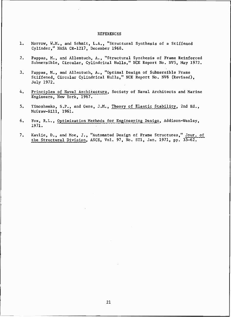
REFERENCES
1. Morrow, W.M., and Schmit, L.A,, "Structural Synthesis of a Stiffened Cylinder," NASA CR-1217, December 1968.
2. Pappas, M., and Allentuch, A., "Structural Synthesis of Frame Reinforced Submersible, Circular, Cylindrical Hulls," NCE Report No. NV5, May 1972.
3. Pappas, M., and Allentuch, A., "Optimal Design of Submersible Frame Stiffened, Circular Cylindrical Hulls," NCE Report No. NV6 (Revised), July 1972.
4. Principles of Naval Architecture, Society of Naval Architects and Marine Engineers, New York, 1967.
5. Timoshenko, S.P., and Gere, J.M., Theory of Elastic Stability, 2nd Ed., McGraw-Hill, 1961.
6. Fox, R.L., Optimization Methods for Engineering Design, Addison-Wesley, 1971.
7. Kavlie, D., and Moe, J., "Automated Design of Frame Structures," Jour, of the Structural Division, ASCE, Vol. 97, No. ST1, Jan. 1971, pp. 33-62.
21

APPENDIX I: DYNAMIC ANALYSIS
The forces on the cylindrical shell are as shown in Fig. 2. The forces
are expressed in terms of displacements as:
N = Hu' + (Hv/R)v* - (HV/R)w + (D/R)w"
N = HVu' + [(H+HC+HF)/R]v* - [H+HC(l+e,/R) + HF(l+ef/R)]w/R
- [D/R+HC(e +p2/R) + HF(ef+p2/R) ]^j w**
R
N , = (S/R)u* + Svf + (K/R2)w!*
N = (S/R)u* + Sv» - (K/R2)w'*
M = - (D/R)uf - (Dv/R2)v* - Dw" - (Dv/R2)w**
M = (HCe./R + HFef/R)v* - [D/R + HC(e +p2/R) + HF(ef+p2/R)]w/R
- Dvw" - [D + HC(P2-KAR) + HF(p2+a2/R)w**/R
Mx(J) = - (2K/R)(v,+w1*)
M. = (K/R2)u* - (K/R)v' - (2K+Q)wf*/R
K ' 3(|> ' K } 3x
The matrices [K], [K ] and [M] of equation (6) are:
[K] =
Ml
M2
M3
12
v22
'23
M3
'23
'33
kll = " H^2 - (S/R2)n2
k12 = " (Hv+s)An/R
M3 [HVA+DX3 - (K/R2)An2]/R
.2^2 2 ,„2 k22 = " (S+2K/R M - [H+HC(l-e./R) + HF(l-ef/R)]n /R
22

k23 = - (3K+Dv)X2n/R2
+ [D/R2-H+HC(p2/R2-l) + HF(p2/R2-l)]n/R2
- [HC(a^/R2-e(j)) + HF(a3/R2-ef)]n3/R3
k33 = - [H+HCU+e^/R) + HF(l+ef/R)]/Ri
+ 2[D/R+HC(e(|+p2/R) + HF(ef+p2/R)]n2/R3
- DA4 - [2Dv+4K+Q](An/R)2
- [I>fHC(p2+a3/R) + HF(p2-ta3/R)](n/R)4
_kGll ° kG13
[KG] = 0 kG22
k k _ G13 G23
kG23
kG33 _
kGll = - (n2+X2/2)/R kG23 = n/R
kG13 = -> k =
G33 - (n2+A2/2)/R
kG22 = " (n2+x2/2)/R
M =
m 11
m 13
m 22 m
23
m 13
m 23
m 33
m. = t + A(l-e,/R) + B(l-e./R) 11 s <p f
m 13
[t3/(12R) + AC-e^/R) + B(-ef+p2/R)]A
m 22
t (1 + -—- ) + A(l-3e, /R+3p2/R2-a3/R3) s 4R2 <$> K<(> <f>
+ B(l-3ef/R+3p2/R2-a3/R3)
23
m23 = [ts/(6R2) + A(-e(()/R+2p2/R2-aJ/R3)
+ B(-ef/R+2p2/R2-a3/R3)]n
m33 = ts + (x2+n2/R2)tg/12 + A[l-e,/R + (A2+n2/R2)(p?-aJ/R)]
+ B[l-ef/R+(A2+n2/R2)(p2-a3/R)]
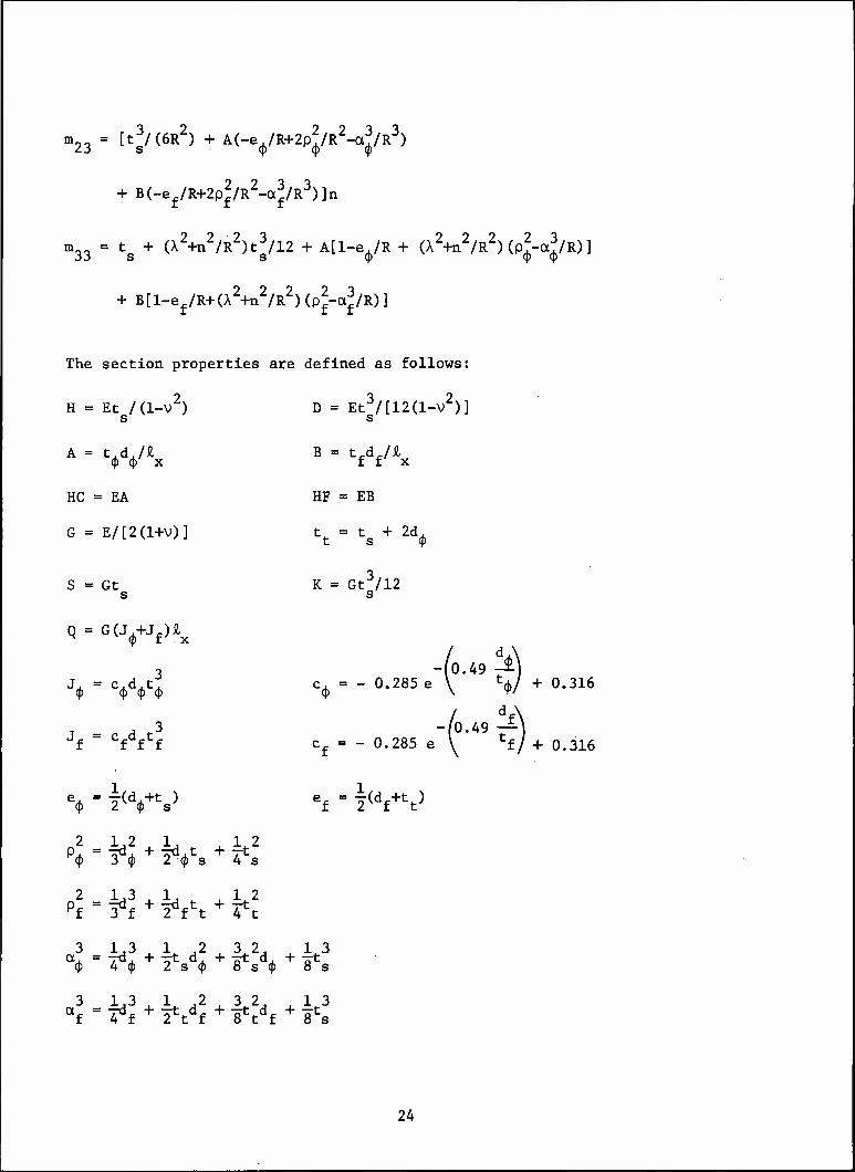
The section properties are defined as follows:
H = Et /(1-V2) D = Et3/[12(1-V2)] s s
A = t,d./£, B = t.dji (J) $ x f f x
HC = EA HF - EB
G = E/[2(1+V)] t = t + 2d *
S = Gt K = Gt3/12 s s
Q = G(J,+J.)£ H <p f :
3 -fo.49 ^) J4, - yy* CCO
= - °-285e V V +0-316
3 -[0.49 —) Jf " Cfdftf cf = - 0.285 e \ tf/ + 0.316
% - TVV ef - l<df-rtt)
P . = -zd , + -rd. t + Tt q> 3 (}) 2 <J) s 4 s
pf = ^f + 2*f \ + 4fct
3 = 1,3 ld232 13 <p 4 (p 2s(p 8 s (p 8s
3 1,3 _,_ 1 ,2 _,_ 3 2, _,_ 13 af = ^f + 2fctdf + äVf + 8*8
24

APPENDIX II: STATIC STRENGTH ANALYSIS
The critical compressive stresses in the skin are assumed to occur on the
outer surface at mid panel. The stresses there are
0(, = - (PR/ts)[l+r(Hn+vHE)]
°x= - (PR/V [I + ™E]
where the various parameters are given as:
-PR/t = hoop stress
R = radius to mid plane of shell
r = [l-v/2-B]/(l+ß)
B = ratio of shell area under frame web to total frame area = t t,/A s <p
A = t t, + t,d, + trd. s <p 99 f f
3 = 2N{l/[3(l-V2)]}1/4(Rt3)1/2/A s
N = (cosh9-cos9)/(sinhe+sin0)
9 = S,[3(l-v2)/(Rts)2]1/4
% = unsupported length of shell = £ - t,
H = - 2[sinh(e/2)cos(e/2)+cosh(6/2)sin(e/2)]/(sinh9+sine)
H^ = - 2[3/(l-V2)]1/2[sinh(e/2)cos(9/2)-cosh(e/2)sin(e/2)]/(sinhe+sin6)
The hoop compressive stress in the frame is
O = PVR/A
where V is a load factor given as:
V = t<J)[l+(l-V/2)3/B]/(l+B)
25

Distribution List
Chief of Naval Research Department of the Navy Arlington, Virginia 22217 Attn: Code 439 (2)
471
Watervliet Arsenal MAGGS Research Center Watervliet, New York 12189 Attn: Director of Research
Director ONR Branch Office 495 Summer Street Boston, Massachusetts 02210
Director ONR Branch Office 219 S. Dearborn Street Chicago, Illinois 60604
Director Naval Research Laboratory Attn: Library, Code 2029 (ONRL) Washington, D.C. 20390 (6)
Commanding Officer ONR Branch Office 207 West 24th Street New York, New York 10011
Director ONR Branch Office 1030 E. Green Street Pasadena, California 91101
U. S. Naval Research Laboratory Attn: Technical Information Div. Washington, D.C. 20390 (6)
Defense Documentation Center Cameron Station Alexandria, Virginia 22314 (20)
Army
Commanding Officer U.S. Army Research Office Durham Attn: Mr. J.J. Murray CRD-AA-IP Box CM, Duke Station Durham, North Carolina 27706
Commanding Officer AMXMR-ATL Attn: Mr. J. Bluhm U.S. Army Materials Res. Agcy. Watertown, Massachusetts 02172
Redstone Scientific Info. Center Chief, Document Section U.S. Army Missile Command Redstone Arsenal, Alabama 35809
Army R&D Center Fort Belvoir, Virginia 22060
Technical Library Aberdeen Proving Ground Aberdeen, Maryland 21005
Navy
Commanding Officer and Director Naval Ship Research & Development Center Washington, D.C. 20007 Attn: Code 042 (Tech. Lib. Br.)
700 (Struc. Mech. Lab.) 720 725 727 012.2 (dr. W.J. Sette)
Naval Weapons Laboratory Dahlgren, Virginia 22448
Naval Research Laboratory Washington, D.C. 20390 Attn: Code 8400
8410 8430 8440 6300 6305 6380
Undersea Explosion Research Div. Naval Ship R&D Center Norfolk Naval Shipyard Portsmouth, Virginia 23709 Attn: Dr. Schauer Code 780
26
Naval Ship R&D Center Annapolis Division Annapolis, Maryland 21402 Attn: Code A800, Mr. W. L. Williams
Technical Library Naval Underwater Weapons Center Pasadena Annex 3202 East Foothill Blvd. Pasadena, California 91107
U.S. Naval Weapons Center China Lake, California 93557 Attn: Code 4520 Mr. Ken Bischel
U.S. Naval Ordnance Laboratory Mechanics Division RFD 1, White Oak Silver Spring, Maryland 20910
U.S. Naval Ordnance Laboratory Attn: Mr. H. A. Perry, Jr. Non-Metallic Materials Division Silver Spring, Maryland 20910
Technical Director U.S. Naval Undersea R&D Center San Diego, California 92132
Supervisor of Shipbuilding U.S. Navy Newport News, Virginia 23607
Technical Director Mare Island Naval Shipyard Vallejo, California 94594
U.S. Naval Ordnance Station Attn: Mr. Garet Bornstein Research & Development Division Indian Head, Maryland 20640
Chief of Naval Operations Department of the Navy Washington, D.C. 20350 Attn: Code OP-07T
Deep Submergence Systems Naval Ship Systems Command Code 39522 Department of the Navy Washington, D.C. 20360 Attn: Chief Scientist
Director, Aero Mechanics Naval Air Development Center Johnsville Warminster, Pennsylvania 18974
Naval Air Systems Command Department of the Navy Washington, D.C. 20360 Attn: NAIR 320 Aero & Structures
5320 Structures 604 Tech. Library
52031F Materials
Naval Facilities Engineering Command Department of the Navy Washington, D.C. 20360 Attn: NFAC 03 Res. & Development
04 Engineering & Design 14114 Tech. Library
Naval Ship Systems Command Department of the Navy Washington, D.C. 20360 Attn: NSHIP 031 Ch. Scientists for R&D
0342 Ship Mats. & Structs. 2052 Tech. Library
Naval Ship Engineering Center Prince George Plaza Hyattsville, Maryland 20782 Attn: NSEC 6100 Ship Sys. Engr. & Des.
6102C Computer-Aided Ship Des. 6105 Ship Protection 6110 Ship Concept Design 6120 Hull Div.
6120D Hull Div. 6128 Surface Ship Struct. 6129 Submarine Struct.
Naval Ordnance Systems Command Department of the Navy Washington, D.C. 20360 Attn: NORD 03 Res. & Technology
035 Weapons Dynamics 9132 Tech. Library
Engineering Department U.S. Naval Academy Annapolis, Maryland 21402
27

Air Force
Commander WADD Wright-Patterson Air Force Base Dayton, Ohio 45433 Attn: Code WWRMDD
AFFDL (FDDS) Structures Division
AFLC (MCEEA) Code WWRC
AFML (MAAM)
Commander Chief, Applied Mechanics Group U.S. Air Force Inst. of Tech. Wright-Patterson Air Force Base Dayton, Ohio 45433
Chief, Civil Engineering Branch WLRC, Research Division Air Force Weapons Laboratory Kirtland AFB, New Mexico 87117
Air Force Office of Scientific Res. 1400 Wilson Blvd. Arlington, Virginia 22209 Attn: Mechs. Div.
NASA
Structures Research Division National Aeronautics and Space Admin. Langley Research Center Langley Station Hampton, Virginia 23365 Attn: Mr. R.R. Heldenfels, Chief
National Aeronautics & Space Admin. Associate Administrator for Advanced
Research & Technology Washington, D.C. 20546
Scientific & Tech. Info. Facility NASA Representative (S-AK/DL) P.O. Box 5700 Bethesda, Maryland 20014
Other Government Activities
Technical Director Marine Corps Development & Educ. Command Quantico, Virginia 22134
Director National Bureau of Standards Washington, D.C. 20234 Attn: Mr. B.L. Wilson, EM 219
National Science Foundation Engineering Division Washington, D.C. 20550
Director STBS Defense Atomic Support Agency Washington, D.C. 20350
Commander Field Command Defense Atomic Support Agency Sandia Base Albuquerque, New Mexico 87115
Chief, Defense Atomic Support Agcy. Blast & Shock Division The Pentagon Washington, D.C. 20301
Director Defense Research & Engr. Technical Library Room 3C-128 The Pentagon Washington, D.C. 20301
Chief, Airframe & Equipment FS-120 Office of Flight Standards Federal Aviation Agency Washington, D.C. 20553
Chief of Research and Development Maritime Administration Washington, D.C. 20235
Mr. Milton Shaw, Director Div. of Reactor Develop. & Technology Atomic Energy Commission Germantown, Maryland 20767
Ship Hull Research Committee National Research Council National Academy of Sciences 2101 Constitution Avenue Washington, D.C. 20418 Attn: Mr. A.R. Lytle
28

PART 2 - CONTRACTORS AND OTHER TECHNICAL COLLABORATORS
Universities
Professor J.R. Rice Division of Engineering Brown University Providence, Rhode Island 02912
Dr. J. Tinsley Oden Dept. of Engr. Mechs. University of Alabama Huntsville, Alabama 35804
Professor R.S. Rivlin Center for the Application of Mathematics Lehigh University Bethlehem, Pennsylvania 18015
Professor Julius Miklowitz Div. of Engr. & Applied Sciences California Institute of Technology Pasadena, California 91109
Professor George Sih Department of Mechanics Lehigh University Bethlehem, Pennsylvania 18015
Dr. Harold Liebowitz, Dean School of Engrg. & Applied Science George Washington University 725 23rd Street Washington, D.C. 20006
Professor Eli Sternberg Div. of Engrg. & Applied Sciences California Institute of Technology Pasadena, California 91109
Professor Burt Paul University of Pennsylvania Towne School of Civil & Mech. Engrg. Room 113 Towne Building 220 So. 33rd Street Philadelphia, Pennsylvania 19104
Professor S.B. Dong University of California Department of Mechanics Los Angeles, California 90024
Professor Paul M. Naghdi Div. of Applied Mechanics Etcheverry Hall University of California Berkeley, California 94720
Professor W. Nachbar University of California Dept. of Aerospace & Mech. Engrg. La Jolla, California 92037
Professor J. Baltrukonis Mechanics Division The Catholic Univ. of America Washington, D.C. 20017
Professor A.J. Durelli Mechanics Division The Catholic Univ. of America Washington, D.C. 20017
Professor H.H. Bleich Dept. of Civil Engineering Columbia University Amsterdam & 120th Street New York, New York 10027
Professor R.D. Mindlin Dept. of Civil Engineering Columbia University S.W. Mudd Building New York, New York 10027
Professor A.M. Freudenthal George Washington University School of Engrg. & Applied Science Washington, D.C. 20006
Professor B.A. Boley Dept. of Theoretical & Applied Mechanics Cornell University Ithaca, New York 14850
Professor P.G. Hodge Department of Mechanics Illinois Institute of Technology Chicago, Illinois 60616
Dr. D.C. Drucker Dean of Engineering University of Illinois Urbana, Illinois 61801
29

Professor N.M. Newmark Dept. of Civil Engineering University of Illinois Urbana, Illinois 61801
Professor A.C. Eringen Dept. of Aerospace & Mech. Sciences Princeton University Princeton, New Jersey 08540
Professor James Mar Massachusetts Institute of Technology Room 33-318 Dept. of Aerospace & Astro. 77 Massachusetts Avenue Cambridge, Massachusetts 02139
Library (Code 0384) U.S. Naval Postgraduate School Monterey, California 93940
Dr. Francis Cozzarelli Div. of Interdisciplinary Studies &
Research School of Engineering State University of New York Buffalo, New York 14214
Professor R.A. Douglas Dept. of Engrg. Mechs. North Carolina State University Raleigh, North Carolina 27607
Dr. George Herrmann Stanford University Dept. of Applied Mechanics Stanford, California 94305
Professor J.D. Achenbach Technological Institute Northwestern University Evanston, Illinois 60201
Director, Ordnance Research Lab. Pennsylvania State University P.O. Box 30 State College, Pennsylvania 16801
Professor J. Kempner Dept. of Aero Engrg. & Applied Mech. Polytechnic Institute of Brooklyn 333 Jay Street Brooklyn, New York 11201
Professor J. Klosner Polytechnic Institute of Brooklyn 333 Jay Street Brooklyn, New York 11201
Dr. S.L. Koh School of Aero., and Engrg. Sei. Purdue University Lafayette, Indiana 47907
Professor R.A. Schapery Civil Engineering Department Texas A & M University College Station, Texas 77840
Professor E.H. Lee Div. of Engrg. Mechanics Stanford University Stanford, California 94305
Dr. Nicholas J. Hoff Dept. of Aero. & Astro. Stanford University Stanford, California 94305
Professor Max Anliker Dept. of Aero & Astro. Stanford University Stanford,California 94305
Professor Chi-Chang Chao Div. of Engrg. Mechanics Stanford University Stanford, California 94305
Professor H.W. Liu Dept. of Chemical Engrg. and Metal, Syracuse University Syracuse, New York 13210
Professor S. Bodner Technion R&D Foundation Haifa, Israel
Dr. S. Dhawan, Director Indian Institute of Science Bangalore, India
Professor Tsuyoshi Hayashi Department of Aeronautics Faculty of Engineering University of Tokyo BUNKYO-KU Tokyo, Japan
30

Professor J.E. Fitzgerald, Ch. Dept. of Civil Engineering University of Utah Salt Lake City, Utah 84112
Professor R.J.H. Bollard Chairman, Aeronautical Engrg. Dept. 207 Guggenheim Hall University of Washington Seattle, Washington 98105
Professor Albert S. Kobayashi Dept. of Mechanical Engrg. University of Washington Seattle, Washington 98105
Professor G.R. Irwin Dept. of Mech. Engrg. Lehigh University Bethlehem, Pennsylvania 18015
Dr. Daniel Frederick Dept. of Engrg. Mechs. Virginia Polytechnic Inst. Blacksburg,Virginia 24061
Professor Lambert Tall Lehigh University Department of Civil Engrg. Bethlehem, Pennsylvania 18015
Professor M.P. Wnuk South Dakota State University Department of Mechanical Engineering Brookings, South Dakota 57006
Professor R.B. Testa Dept. of Civil Engrg. Columbia University S.W. Mudd Bldg. New York, New York 10027
Dr. Y. Weitsman Dept. of Engrg. Sciences Tel-Aviv University Ramat-Aviv Tel-Aviv, Israel
Professor W.D. Pilkey Dept. of Aerospace Engrg. University of Virginia Charlottesville, Virginia 22903
Professor W. Prager Division of Engineering Brown University Providence, Rhode Island 02912
Industry and Research Institutes
Mr. Carl E. Hartbower Dept. 4620, Bldg. 2019 A2 Aerojet-General Corporation P.O. Box 1947 Sacramento, California 95809
Library Services Department Report Section, Bldg. 14-14 Argonne National Lab. 9400 S. Cass Avenue Argonne, Illinois 60440
Professor Norman Jones Dr. F. R. Schwarzl Massachusetts Institute of Technology Central Laboratory T.N.O. Dept. of Naval Architecture & Marine Engrg. Schoemakerstraat 97 Cambridge, Massachusetts 02139 Delft, The Netherlands
Professor Pedro V. Marcal Brown University Division of Engineering Providence, Rhode Island 02912
Professor Werner Goldsmith Department of Mechanical Engineering Division of Applied Mechanics University of California Berkeley, California 94720
Dr. Wendt Valley Forge Space Technology Cen. General Electric Co. Valley Forge, Pennsylvania 10481
Library Newport News Shipbuilding & Dry Dock Company
Newport News, Virginia 23607
31

Director Ship Research Institute Ministry of Transportation 700, SHINKAWA Mitaka Tokyo, Japan
Dr. H.N Abramson Southwest Research Institute 8500 Culebra Road San Antonio, Texas 78206
Dr. R.C. DeHart Southwest Research Institute 8500 Culebra Road San Antonio, Texas 78206
Mr, Roger Weiss High Temp. Structures & Materials Applied Physics Lab. 8621 Georgia Avenue Silver Spring, Maryland 20910
Mr. E.C. Francis, Head Mech. Props. Eval. United Technology Center Sunnyvale, California 94088
Mr. D. Wilson Litton Systems, Inc. AMTD, Dept. 400 El Segundo 9920 W. Jefferson Blvd. Culver City, California 90230
Dr. Kevin J. Forsberg, Head Solid Mechanics Orgn 52-20, Bldg. 205 Lockheed Palo Alto Research Lab. Palo Alto, California 94302
Dr. E.M.Q. Roren, Head Research Department Det Norske Veritas Post Box 6060 Oslo, Norway
Dr. Andrew F. Conn Hydronautics, Incorporated Pindell School Road, Howard County Laurel, Maryland 20810
Mr. C.N. Robinson Atlantic Research Corp. Shirley Highway at Edsall Road Alexandria, Virginia 22314
Mr. P.C. Durup Aeromechanics Dept., 74-43 Lockheed-California Co. Burbank, California 91503
32
