finn-aqua medium and large t-series multiple …
TRANSCRIPT

FINN-AQUA® MEDIUM AND LARGE T-SERIESMULTIPLE-EFFECT WATER STILLS
NORTH AMERICA
APPLICATION
Finn-Aqua Multiple-Effect Water Stills (MWS) are designed to consistently generate Water for Injection (WFI). The produced WFI is intended for use in the preparation of parenteral solutions, for washing and final rinse in GMP washers and terminal sterilizers.
DESCRIPTION
Finn-Aqua T-Series Multiple-Effect Water Stills operate based on Finn-Aqua’s original, proven falling film design to remove pyrogenic material. The water stills are steam heated and include a Programmable Logic Controller (PLC) for easy operation and monitoring. The Multiple-Effect Water Stills are designed, manufactured, tested and documented to current Good Manufacturing Practices (cGMP) compliance. The quality of the generated WFI meets or exceeds the latest versions of United States Pharmacopeia (USP), European Pharmacopeia (EP) and Japanese Pharmacopeia (JP) WFI specifications.
The Selections Checked B
CONTROL❑ Siemens❑ Allen-BradleyVOLTAGE❑ 300-500 Vac, 50 Hz, 3-Phase❑ 208-480 Vac, 60 Hz, 3-PhaseCONTROL SYSTEM AND INSTRUMENTATION
OPTIONS❑ Control Cabinet Accessories Upgrade❑ Siemens Control System Hardware Upgrade to
MP277-8 soft PLC❑ SCADA Communication (Siemens Control)❑ Allen-Bradley ControlLogix with PV 1000+❑ Allen-Bradley Upgrade Industrial EtherNet
Connection❑ Feed Water Conductivity Sensor and Recorder
Pen❑ Feed Water Sample Valve, Diaphragm Type❑ Utility Monitoring and Measurement Option with
Endress+Hauser Process Instrumentation❑ Two-Channel Pen Chart Recorder for WFI❑ Three-Channel Pen Chart Recorder for WFI and
FW❑ Six-Channel Paperless Recorder (21 CFR Part 11
Compliant)❑ Ground Fault Indicator (GFI)/Allen-Bradley
Controls
MECHANICAL OPTIO❑ Plant (Heating) St❑ Feed Water Gas S❑ Utilities Monitorin❑ Automatic Feed W❑ Distillation Agains❑ Piping Sanitization❑ Nonevaporated Fe❑ Continuous Blowd❑ Simultaneous Dis
Production❑ Pure Steam Gene❑ Proportional Capa❑ Effluent Cooler fo❑ Effluent Cooler fo❑ Closed Loop Cool
System❑ Softened Feed Wa❑ Stainless-Steel Fr❑ Seismic Restraint❑ Additional Passiva
Test (FAT)
(Typical only - some details may vary.)
SD805 (04/01/10)
Item ________________________Location(s)___________________
____________________________
elow Apply To This Equipment
NSeam Pressure Reducing Valveeparation Optiong and Measurement Optionater Valvet Back Pressure
ed Water Recirculationown Measurement
tillation and Pure Steam
rator (PSG) Operationcity Control (PCC) Operation
r Reject Distillater Blowdowning Water Recirculation
ter Optionames and Calculationstion After Factory Acceptance
MANUFACTURING TESTING AND DOCUMENTATION OPTIONS
❑ Extended Pressure Vessel and Piping Documentation
❑ Manufacturing Procedures Documentation❑ Extended Control System Validation
Documentation❑ FAT Procedures and Results❑ Component Data Sheets❑ Loop Diagrams❑ Additional Copy of Documentation❑ Surface Finish Inspection Report (Pressure
Vessel and Piping)❑ Boroscope Inspection of Pipe Welding on CD❑ USP/EP/JP WFI Test❑ Endotoxin Challenge Test (Pure Steam and Feed
Water)OPTIONAL FACTORY ACCEPTANCE TESTING❑ Additional FAT per DaySPARE PARTS❑ Spare Parts Kit❑ Installation Kit

STANDARDS
The Finn-Aqua T-Series Multiple-Effect Water Stills meet the applicable requirements for the following:
• cGMP, CFR Title 21, Part 211, Section D
• Good Automation Manufacturing Practices (GAMP 5), A Risk-Based Approach to Compliant GxP Computerized Systems
• ISO 9001:2000 Certification, Approved by Lloyd’s Register Quality Assurance Limited
• 97/23/EC (Pressure Equipment Directive) Certification, Module H/H1 and SFS-EN ISO 3834-2
• Certification of Authorization to Use ASME Code "U"-stamp
• CE Compliance
» Pressure Equipment Directive 97/23/EC
» Machine Directive 2006/42/EC of 17 May 2006
» Low Voltage Directive 2006/95/EC of 12 Dec. 2006
» Electro Magnetic Compatibility 2004/108/EC
• ASME BPE 2007
• International Electric Code IEC 60204-1/EN 60204-1
• UL 508 Standard for Industrial Control Equipment
• National Electrical Code (NEC)
• Canadian Standards Association (CSA)
FEATURES
Three-Stage Separation Process
Finn-Aqua's patented three-stage separation technology ensures high quality WFI free of endotoxins, pyrogens and droplets. The three-stage separation provides:
• Separation by falling film evaporation
• Gravity separation by 180° steam flow turn
• Centrifugal separation where only pure steam flow can enter to the next column as heating steam
Continuous Blowdown
Finn-Aqua utilizes an unique distillation process within the water stills. Concentrated feed water containing all impurities, pyrogens and harmful particles is considered "blowdown" and is directed to drain. This blowdown removal is continuous, providing the following advantages:
• Reliable distillation in all process conditions
• Highest WFI quality
• WFI production is a continuous process, thus blowdown removal is a continuous process
Blowdown Removal from Each Column
Along with continuous blowdown, Finn-Aqua’s unique distillation also has blowdown removal from each column separately, providing the following advantages:
• Impurities are prevented from being transferred to the next stage
• Highest WFI quality
• Reduced plant steam and feed water use: the rejected rate (blowdown) is from 12-15%. With special nonevaporated feed water recirculation option, the blowdown amount can be reduced down to 5%*.
Unique Pipe Joining Method
Within all the columns, preheaters and condensers, the heat exchanger pipes are expanded to the flanges without welding. This provides:
• No thermal cracking
• Less maintenance and shut-down period
• Long heat exchanger life length
Single point power supply
• Requires only one power connection to the unit
Small footprint and height
• Reduced external dimension enables the equipment to be installed in rooms with limited space
* The Finn-Aqua T-Series Multiple-Effect Water Stills reduce plant steam consumption by 5% and feed water consumption by 7-10% over previous models with nonevaporated feed water recirculation option.
Typical Multiple-Effect Water Still First Column Cross Sectional Detail with Feed Water Gas Removal Option
Feed Water InletGas Outlet
Plant Steam Inlet
Evaporator
Condensate OutletPure Steam
OutletSpiral
Cylinder SpaceRiser Space
Observation Glass
Blowdown Outlet
Feed Water Circulation
Double Tube Sheet
Gas Separator
2
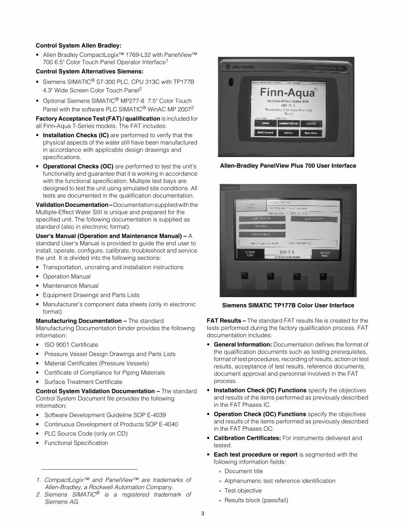
Control System Allen Bradley:
• Allen Bradley CompactLogix™ 1769-L32 with PanelView™ 700 6.5" Color Touch Panel Operator Interface1
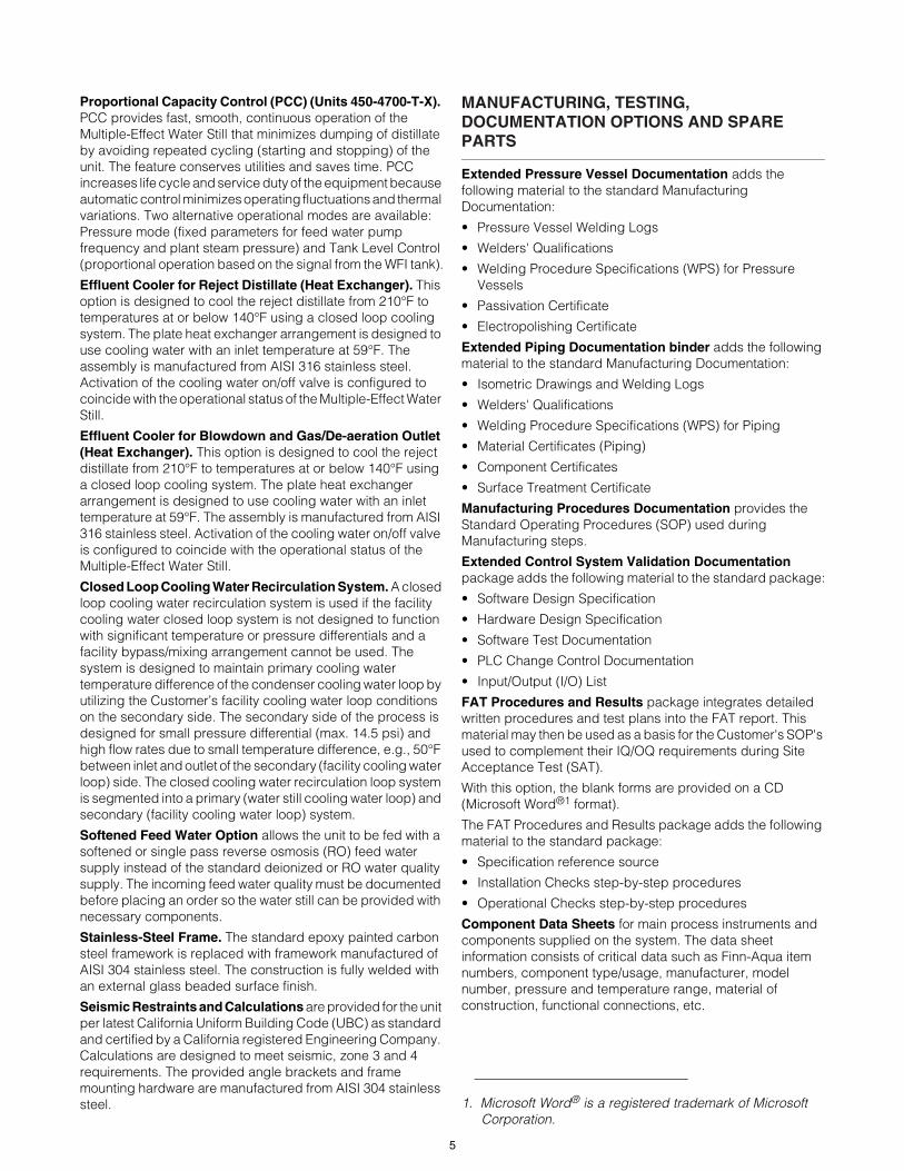
Control System Alternatives Siemens:
• Siemens SIMATIC® S7-300 PLC, CPU 313C with TP177B 4.3" Wide Screen Color Touch Panel2
• Optional Siemens SIMATIC® MP277-8 7.5" Color Touch Panel with the software PLC SIMATIC® WinAC MP 20072
Factory Acceptance Test (FAT) / qualification is included for all Finn-Aqua T-Series models. The FAT includes:
• Installation Checks (IC) are performed to verify that the physical aspects of the water still have been manufactured in accordance with applicable design drawings and specifications.
• Operational Checks (OC) are performed to test the unit's functionality and guarantee that it is working in accordance with the functional specification. Multiple test bays are designed to test the unit using simulated site conditions. All tests are documented in the qualification documentation.
Validation Documentation – Documentation supplied with the Multiple-Effect Water Still is unique and prepared for the specified unit. The following documentation is supplied as standard (also in electronic format):
User's Manual (Operation and Maintenance Manual) – A standard User's Manual is provided to guide the end user to install, operate, configure, calibrate, troubleshoot and service the unit. It is divided into the following sections:
• Transportation, uncrating and installation instructions
• Operation Manual
• Maintenance Manual
• Equipment Drawings and Parts Lists
• Manufacturer's component data sheets (only in electronic format)
Manufacturing Documentation – The standard Manufacturing Documentation binder provides the following information:
• ISO 9001 Certificate
• Pressure Vessel Design Drawings and Parts Lists
• Material Certificates (Pressure Vessels)
• Certificate of Compliance for Piping Materials
• Surface Treatment Certificate
Control System Validation Documentation – The standard Control System Document file provides the following information:
• Software Development Guideline SOP E-4039
• Continuous Development of Products SOP E-4040
• PLC Source Code (only on CD)
• Functional Specification
FAT Results – The standard FAT results file is created for the tests performed during the factory qualification process. FAT documentation includes:
• General Information: Documentation defines the format of the qualification documents such as testing prerequisites, format of test procedures, recording of results, action on test results, acceptance of test results, reference documents, document approval and personnel involved in the FAT process.
• Installation Check (IC) Functions specify the objectives and results of the items performed as previously described in the FAT Phases IC.
• Operation Check (OC) Functions specify the objectives and results of the items performed as previously described in the FAT Phases OC:
• Calibration Certificates: For instruments delivered and tested.
• Each test procedure or report is segmented with the following information fields:
» Document title
» Alphanumeric test reference identification
» Test objective
» Results block (pass/fail)
1. CompactLogix™ and PanelView™ are trademarks ofAllen-Bradley, a Rockwell Automation Company.
2. Siemens SIMATIC® is a registered trademark ofSiemens AG.
Allen-Bradley PanelView Plus 700 User Interface
Siemens SIMATIC TP177B Color User Interface
3

OPTIONAL FEATURES
Control Cabinet Accessories Upgrade. The control cabinet is equipped with cabinet light, electrical socket, 240 V or 120 V, and ventilation grate and ventilation fan to cool down the cabinet.
Allen-Bradley Industrial EtherNet Connection includes hardware components to enable data reading from Central Processing Unit (CPU) (all Operator Interface [OI's], process steps and alarms). Additionally, the unit can be stopped/started and acknowledge the active alarms.
Supervisory Control and Data Acquisition (SCADA) Communication (Siemens) contains hardware component (SIMATIC NET SCALANCE S602-module) for the data communication between the control system of T-MWS and the Customer's SCADA system.
Allen-Bradley ControlLogix™ with PanelView™ Plus 10001 option replaces the standard Allen-Bradley CompactLogix with ControlLogix and PanelView Plus 1000.
Feed Water Conductivity Sensor and Recorder Pen.Feed water line is fitted with a conductivity probe to monitor the feed water quality in conductivity or resistivity. This probe is used with the two-channel conductivity analyzer provided with the unit. Feed water recorder pen is installed in the system to enable the recorder to record the feed water conductivity or resistivity.
Utility Monitoring and Measurement Option with Endress+Hauser Process Instrumentation. The standard instrumentation of the unit is replaced by Endress+Hauser Process Instruments. Temperature, pressure, conductivity and flow instruments are changed.
Recorder options. Two- or three- channel pen chart recorders are provided to continuously record the distillate and/or feed water conductivity or resistivity. Also a 21 CFR Part 11 compatible, six-channel paperless recorder is available. The acquired process information can be stored onto a Compact Flash card or transferred online to the client's network for further analysis. Typically, this recorder is used for recording feed water and distillate conductivity/resistivity and distillate temperature, and to print the position of the diverting valve. Other free channels are available for Customer use.
Plant (Heating) Steam Pressure Reducing Valve. For Multiple-Effect Water Stills, the plant steam pressure is reduced and stabilized by using a Pressure Reducing Valve (PRV) installed in the plant steam line. The PRV allows the plant steam pressure to be manually adjusted between 44 - 116 psig as required. A PRV is also required if Customer's plant steam supply pressure exceeds 125 psig or is unstable.
Feed Water Gas Separation Option adds Finn-Aqua’s unique Gas Separation system to the feed water line before the column. A feed water spray nozzle for gas separation and a feed water distribution plate are installed to the top of the first column. Piping and necessary components are installed from the column top to the drain line. With this option, the produced pure steam fulfills the HTM2010 (EN285) requirements.
Utilities Monitoring and Measurement Option adds temperature elements/transmitters for columns. It also adds pressure switches and pressure gauges to monitor/measure the utilities and their availability.
Automatic Feed Water On/Off Valve adds an automatic feed water on/off valve to the feed water line, and is controlled by the unit control system.
Distillation Against Back Pressure. As standard, the Multiple-Effect Water Still is designed for gravity discharge of distillate. With this option, the process is designed to operate against 4.35 psig/9 ft back pressure to overcome the WFI distribution system back pressure. This feature eliminates the need for additional sub-frames, distillate pumps or other modifications. This option is typically selected when the distillate outlet from the Multiple-Effect Water Still is lower than the tank inlet or there is back pressure in the WFI tank such as from a nitrogen blanket.
Piping Sanitation. As standard, the Multiple-Effect Water Still goes through a preconfigured sanitization step. This step sanitizes the pure steam and WFI contact surfaces. This option is designed to sanitize the feed water piping in addition to the pure steam and WFI piping. The water still is equipped with accessories to allow sanitizing above 176°F of all feed water piping, preheaters, columns and condensers.
Nonevaporated Feed Water Recirculation. This option is intended to reduce the total feed water consumption. Two-thirds of the nonevaporated feed water (blowdown) is directed back to the feed water tank for recirculation. The feature decreases the total blowdown percentage to 5%, ±2%.
Continuous Blowdown Measurement. With this option, the blowdown is directed to an external graduated container before discharge to drain. The blowdown amount is continuously measured and the blowdown percentage is displayed on the operator panel.
Simultaneous Distillation and Pure Steam Production (Units 450-4700-T-X). This option enables the Multiple-Effect Water Still to produce WFI and pure steam simultaneously. The pure steam outlet pressure from the Multiple-Effect Water Still is at maximum 44 psig ±7 psig), based on a minimum plant steam pressure of 72 psig. The control system monitors and automatically adjusts the plant steam and feed water pressures to maintain the user configured pure steam set pressure. While this feature is activated, the distillate capacity is reduced. The resulting capacity reduction depends on the pure steam consumption. Pure steam production is approx. 30% of the same size PSG-T with same utility values.
Pure Steam Generator (PSG) Operation (Units 450-2900-T-X). This option enables the Multiple-Effect Water Still to produce pure steam at the capacity of 70% when compared to an equal size T-model pure steam generator capacity at equal operating point (plant steam pressure vs. pure steam pressure). During this process phase, the unit produces pure steam by using the first column only. Simultaneous distillate production is prevented by automatic valves isolating the rest of the unit from the first column.
1. CompactLogix™ and PanelView™ are trademarks ofAllen-Bradley, a Rockwell Automation Company.
4
Proportional Capacity Control (PCC) (Units 450-4700-T-X). PCC provides fast, smooth, continuous operation of the Multiple-Effect Water Still that minimizes dumping of distillate by avoiding repeated cycling (starting and stopping) of the unit. The feature conserves utilities and saves time. PCC increases life cycle and service duty of the equipment because automatic control minimizes operating fluctuations and thermal variations. Two alternative operational modes are available: Pressure mode (fixed parameters for feed water pump frequency and plant steam pressure) and Tank Level Control (proportional operation based on the signal from the WFI tank).
Effluent Cooler for Reject Distillate (Heat Exchanger). This option is designed to cool the reject distillate from 210°F to temperatures at or below 140°F using a closed loop cooling system. The plate heat exchanger arrangement is designed to use cooling water with an inlet temperature at 59°F. The assembly is manufactured from AISI 316 stainless steel. Activation of the cooling water on/off valve is configured to coincide with the operational status of the Multiple-Effect Water Still.
Effluent Cooler for Blowdown and Gas/De-aeration Outlet (Heat Exchanger). This option is designed to cool the reject distillate from 210°F to temperatures at or below 140°F using a closed loop cooling system. The plate heat exchanger arrangement is designed to use cooling water with an inlet temperature at 59°F. The assembly is manufactured from AISI 316 stainless steel. Activation of the cooling water on/off valve is configured to coincide with the operational status of the Multiple-Effect Water Still.
Closed Loop Cooling Water Recirculation System. A closed loop cooling water recirculation system is used if the facility cooling water closed loop system is not designed to function with significant temperature or pressure differentials and a facility bypass/mixing arrangement cannot be used. The system is designed to maintain primary cooling water temperature difference of the condenser cooling water loop by utilizing the Customer’s facility cooling water loop conditions on the secondary side. The secondary side of the process is designed for small pressure differential (max. 14.5 psi) and high flow rates due to small temperature difference, e.g., 50°F between inlet and outlet of the secondary (facility cooling water loop) side. The closed cooling water recirculation loop system is segmented into a primary (water still cooling water loop) and secondary (facility cooling water loop) system.
Softened Feed Water Option allows the unit to be fed with a softened or single pass reverse osmosis (RO) feed water supply instead of the standard deionized or RO water quality supply. The incoming feed water quality must be documented before placing an order so the water still can be provided with necessary components.
Stainless-Steel Frame. The standard epoxy painted carbon steel framework is replaced with framework manufactured of AISI 304 stainless steel. The construction is fully welded with an external glass beaded surface finish.
Seismic Restraints and Calculations are provided for the unit per latest California Uniform Building Code (UBC) as standard and certified by a California registered Engineering Company. Calculations are designed to meet seismic, zone 3 and 4 requirements. The provided angle brackets and frame mounting hardware are manufactured from AISI 304 stainless steel.
MANUFACTURING, TESTING, DOCUMENTATION OPTIONS AND SPARE PARTS
Extended Pressure Vessel Documentation adds the following material to the standard Manufacturing Documentation:
• Pressure Vessel Welding Logs
• Welders' Qualifications
• Welding Procedure Specifications (WPS) for Pressure Vessels
• Passivation Certificate
• Electropolishing Certificate
Extended Piping Documentation binder adds the following material to the standard Manufacturing Documentation:
• Isometric Drawings and Welding Logs
• Welders' Qualifications
• Welding Procedure Specifications (WPS) for Piping
• Material Certificates (Piping)
• Component Certificates
• Surface Treatment Certificate
Manufacturing Procedures Documentation provides the Standard Operating Procedures (SOP) used during Manufacturing steps.
Extended Control System Validation Documentation package adds the following material to the standard package:
• Software Design Specification
• Hardware Design Specification
• Software Test Documentation
• PLC Change Control Documentation
• Input/Output (I/O) List
FAT Procedures and Results package integrates detailed written procedures and test plans into the FAT report. This material may then be used as a basis for the Customer's SOP's used to complement their IQ/OQ requirements during Site Acceptance Test (SAT).
With this option, the blank forms are provided on a CD (Microsoft Word®1 format).
The FAT Procedures and Results package adds the following material to the standard package:
• Specification reference source
• Installation Checks step-by-step procedures
• Operational Checks step-by-step procedures
Component Data Sheets for main process instruments and components supplied on the system. The data sheet information consists of critical data such as Finn-Aqua item numbers, component type/usage, manufacturer, model number, pressure and temperature range, material of construction, functional connections, etc.
1. Microsoft Word® is a registered trademark of MicrosoftCorporation.
5
Loop Diagrams include individual loop diagrams that are provided for each control loop or inter-connecting wiring between associated equipment and apparatus in the system. The component tag number(s), terminal number(s) and wire colors are indicated in each diagram.
Additional Copy of Documentation. An additional hard copy of the complete documentation set is provided, including the user's manual, FAT documentation, as well as the manufacturing and control system documentation (standard and optional). Manufacturer's booklets and CDs for installation, operation and maintenance for control systems, instrumentation and components are excluded.
Surface Finish Inspection Report (Pressure Vessel and Piping). This option provides surface finish instrument documentation, test procedures, inspection report and surface finish measurement data in μmRa.
Boroscope Inspection of Pipe Welding on DVD. As standard, all feed water, pure steam and distillate line welds are visually inspected during manufacturing according to STERIS Finn-Aqua procedures.
With this option, isometric diagrams are created and all welds are logged. Each weld is then sequentially inspected using a boroscope. The inspection is recorded on a DVD for reference purposes.
European Pharmacopeia/United States Pharmacopeia [EP/USP] WFI Test. A sample of the distillate is extracted from Finn-Aqua Multiple-Effect Water Still and analyzed for the following constituents:
• Current EP water monograph substances
• Colony Forming Units (CFU)
• Total Organic Carbon (TOC) level
Endotoxin Challenge Test (WFI and Feed Water). In order to demonstrate an effective reduction of endotoxins, a Limulus Amebocyte Lysate (LAL) test method can be performed during FAT. To demonstrate the reduction, feed water to the unit is spiked with a minimum of 10 EU/mL endotoxins. The distillate produced must contain less than 0.25 EU/mL (as defined by USP as acceptance level). An independent laboratory performs the LAL test in accordance to international standards. Test procedure and test certificate are supplied with the documentation.
Additional FAT per Day. As standard, a STERIS Finn-Aqua FAT is scheduled for three days. FAT is extended by one day to allow the Customer to perform additional tests.
Spare Parts Kit is provided that contains selected mechanical components to fulfill the requirement for two years of normal maintenance and operation of the water still.
Installation Kit supports an effective installation on the Customer site by providing:
• Gaskets for the utility connections
• Counter (matching) flanges and fittings for all the utility connections
CONSTRUCTION
• Pressure Vessels:
» AISI 316L Stainless-Steel Pressure Vessels. Pressurevessels are designed to a pressure rating of 131 psigat 361°F. Pressure vessels built according to ASME/PEDor many other international standards.
» All heat exchangers in contact with heating steam orfeed water, first column, and preheaters andcondensers are made of a double-tube sheet designpreventing cross-contamination from lower purity mediato higher purity media. The heat exchanger tubes areexpanded, not welded, into the end of tube sheet toavoid thermal cracking.
» Surface finish in contact with distillate, pure steam andfeed water is polished / electropolished to Ra <25 µinch.
» Columns and preheaters are insulated withnoncorrosive mineral wool (in compliance with ASTM C795) with 304 stainless-steel bright annealed sheathing.
• Piping:
» AISI 316L stainless-steel or better piping andcomponents for feed water, pure steam and distillate.All piping located outside of the pressure vessels areaccording to ASTM A269 or A270, ASME SA213/213M.
» Sanitary Flange Connections for clean utilities.
» Orbital Welded Pipes and Components (wheretechnically possible).
» Automatic orbital welding techniques are utilizedwherever technically possible. Argon of minimum99.998% purity is used as protective inert gas.
» Surface finish in contact with distillate, pure steam andfeed water is polished/electropolished to Ra <25 µinch.
» A maximum of 3D for dead legs is maintained on thedistillate, pure steam and feed water lines wherevertechnically possible.
» A capped tri-clamp drain port is located in the lowestpoint of the system. All horizontal pipe runs are slopeda minimum of 1-2° to promote drainage wherevertechnically possible.
» All gaskets used are of pharmaceutical gradeconforming to Food and Drug Administration (FDA)regulations, e.g., Polytetrafluoroethylene (PTFE),Ethylene Propylene Diene Monomer (EPDM) or silicone.
6

UTILITY REQUIREMENTS
Steam44-116 psig
97-100% Saturated Steam
Max. ±5% Pressure Variations
Feed Water30-88 psig
Temperature 50-68°F
Conductivity < 5μS/cm at 77°F
pH 5-7
Silica < 1 ppm
Chloride < 100 ppb
Chlorine < 100 ppb
UNIT DIMENSIONS
Finn-Aqua T-Series Multiple-Effect Water Stills reduced external dimensions enables the equipment to be installed in rooms with limited space
Electrical380-415 V, 50 Hz, 3-Phase
208-600 V, 60 Hz, 3-Phase
Compressed Air88-116 psig
Clean, dry, oil free
Cooling Water44-116 psig
Temperature 41-68°F
Hardness not to exceed 125 ppm as CaCO3 (7° dH)
.
Model
Width (W) (in)
Depth (D)(in)
Height (H)(in)
Height of
Distillate Outlet
(in)
Net Weight (lb)
Number of Columns Number of Columns
4 5 6 7 8 4 5 6 7 8
450-T 75 94 114 N/A N/A 34 111 89 2,180 2,620 3,200 N/A N/A
850-T 75 94 114 N/A N/A 34 111 97 2,890 3,440 4,170 N/A N/A
1600-T N/A 125 150 175 N/A 42 136 110 N/A 4,940 6,020 6,860 N/A
2900-T N/A 125 150 175 200 42 136 118 N/A 7,190 8,660 9,920 10930
4700-T N/A N/A 166 194 222 64 169 144 N/A N/A 10,760 12,390 13,710
D W
H
NOTE: Typical only. Not for construction.
7

CAPACITIES AND CONSUMPTIONS
Finn-Aqua Medium and Large T-Series Multiple-Effect Water Stills are heated by steam supplied at any pressure from 44-116 psig. The following tables reflect the still capacity and consumptions for steam delivered at 116, 102, 87, 73, 58 and 44 psig pressure and distillate output temperature at 210°F.
All plant steam pressure values of these tables indicate the pressure inside the first column. Please add 4% to these values to obtain the pressure level required in the plant steam supply. This is to compensate for the pressure losses in the plant steam inlet.
116Plant Steam Consumption (lb/h)
116 psig/347°F (131 psia)Cooling Water Consumption (gal/h)
44 psig/59°F
Feed Water Pressure
29-87 psig/59°F (44-102 psia)
CapacityUS gal/h
Number of Columns Number of Columns Feed Water Consumption gal/h
Deionized or RO Feed WaterModel 4 5 6 7 8 4 5 6 7 8
450-T 235 666 536 450 N/A N/A 165 81 32 N/A N/A 270
850-T 441 1,250 1,005 847 N/A N/A 309 153 60 N/A N/A 507
1600-T 911 N/A 2,079 1,746 1,504 N/A N/A 316 124 TBD N/A 1,048
2900-T 1,585 N/A 3,616 3,038 2,612 2,302 N/A 549 216 TBD TBD 1,823
4700-T 2,839 N/A N/A 5,443 4,683 4,125 N/A N/A 387 TBD TBD 3,265
102Plant Steam Consumption (lb/h)
102 psig/338°F (116 psia)Cooling Water Consumption (gal/h)
44 psig/59°F
Feed Water Pressure
29-87 psig/59°F (44-102 psia)
CapacityUS gal/h
Number of Columns Number of Columns Feed Water Consumption gal/h
Deionized or RO Feed WaterModel 4 5 6 7 8 4 5 6 7 8
450-T 214 628 507 425 N/A N/A 147 72 27 N/A N/A 246
850-T 415 1,221 983 827 N/A N/A 286 140 53 N/A N/A 477
1600-T 856 N/A 2,028 1,704 1,466 N/A N/A 288 109 TBD N/A 984
2900-T 1,455 N/A 3,448 2,897 2,491 2,194 N/A 490 186 TBD TBD 1,674
4700-T 2,560 N/A N/A 5,095 4,383 3,860 N/A N/A 327 TBD TBD 2,944
87Plant Steam Consumption (lb/h)
87 psig/329°F (102 psia)Cooling Water Consumption (gal/h)
44 psig/59°F
Feed Water Pressure
29-87 psig/59°F (44-102 psia)
CapacityUS gal/h
Number of Columns Number of Columns Feed Water Consumption gal/h
Deionized or RO Feed WaterModel 4 5 6 7 8 4 5 6 7 8
450-T 191 558 450 377 N/A N/A 129 62 23 N/A N/A 220
850-T 366 1,067 860 721 N/A N/A 247 119 43 N/A N/A 421
1600-T 766 N/A 1,799 1,512 1,301 N/A N/A 250 91 TBD N/A 881
2900-T 1,289 N/A 3,027 2,544 2,187 1,927 N/A 420 153 TBD TBD 1,482
4700-T 2,281 N/A N/A 4,500 3,871 3,408 N/A N/A 270 TBD TBD 2,623
8
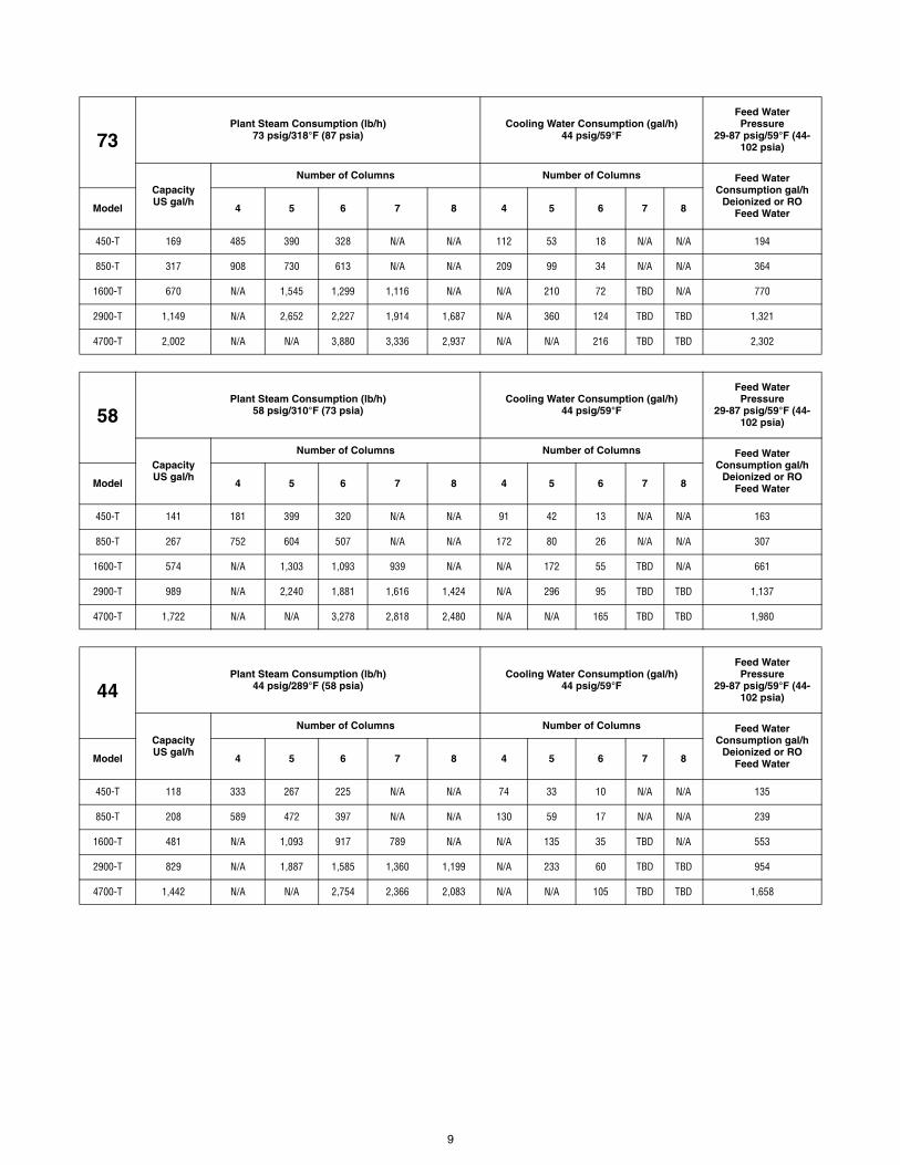
73Plant Steam Consumption (lb/h)
73 psig/318°F (87 psia)Cooling Water Consumption (gal/h)
44 psig/59°F
Feed Water Pressure
29-87 psig/59°F (44-102 psia)
CapacityUS gal/h
Number of Columns Number of Columns Feed Water Consumption gal/h
Deionized or RO Feed WaterModel 4 5 6 7 8 4 5 6 7 8
450-T 169 485 390 328 N/A N/A 112 53 18 N/A N/A 194
850-T 317 908 730 613 N/A N/A 209 99 34 N/A N/A 364
1600-T 670 N/A 1,545 1,299 1,116 N/A N/A 210 72 TBD N/A 770
2900-T 1,149 N/A 2,652 2,227 1,914 1,687 N/A 360 124 TBD TBD 1,321
4700-T 2,002 N/A N/A 3,880 3,336 2,937 N/A N/A 216 TBD TBD 2,302
58Plant Steam Consumption (lb/h)
58 psig/310°F (73 psia)Cooling Water Consumption (gal/h)
44 psig/59°F
Feed Water Pressure
29-87 psig/59°F (44-102 psia)
CapacityUS gal/h
Number of Columns Number of Columns Feed Water Consumption gal/h
Deionized or RO Feed WaterModel 4 5 6 7 8 4 5 6 7 8
450-T 141 181 399 320 N/A N/A 91 42 13 N/A N/A 163
850-T 267 752 604 507 N/A N/A 172 80 26 N/A N/A 307
1600-T 574 N/A 1,303 1,093 939 N/A N/A 172 55 TBD N/A 661
2900-T 989 N/A 2,240 1,881 1,616 1,424 N/A 296 95 TBD TBD 1,137
4700-T 1,722 N/A N/A 3,278 2,818 2,480 N/A N/A 165 TBD TBD 1,980
44Plant Steam Consumption (lb/h)
44 psig/289°F (58 psia)Cooling Water Consumption (gal/h)
44 psig/59°F
Feed Water Pressure
29-87 psig/59°F (44-102 psia)
CapacityUS gal/h
Number of Columns Number of Columns Feed Water Consumption gal/h
Deionized or RO Feed WaterModel 4 5 6 7 8 4 5 6 7 8
450-T 118 333 267 225 N/A N/A 74 33 10 N/A N/A 135
850-T 208 589 472 397 N/A N/A 130 59 17 N/A N/A 239
1600-T 481 N/A 1,093 917 789 N/A N/A 135 35 TBD N/A 553
2900-T 829 N/A 1,887 1,585 1,360 1,199 N/A 233 60 TBD TBD 954
4700-T 1,442 N/A N/A 2,754 2,366 2,083 N/A N/A 105 TBD TBD 1,658
9

Life Sciences
Capital Equipment
10

Life Sciences
Capital Equipment
11

For Further Information, contact:
STERIS Corporation5960 Heisley RoadMentor, OH 44060-1834 • USA440-354-2600 • 800-444-9009www.steris.com
This document is intended for the exclusive use of STERIS Customers, including architects or designers. Reproduction in whole or in part by any party other than a Customer is prohibited.SD805 ©2010, STERIS Corporation. All rights reserved. (04/01/10)