finite volume analysis of a closed die hot … · the finite volume analysis of a closed die ......
TRANSCRIPT
International Journal of Advanced Technology in Engineering and Science www.ijates.com
Volume No.02, Issue No. 07, July 2014 ISSN (online): 2348 – 7550
Page | 169
FINITE VOLUME ANALYSIS OF A CLOSED DIE HOT
FORGING AND COMPARISON WITH WEAR
MEASUREMENT OF THE WORN DIE
Ranjeet Kumar1, Dr. Pushpendra Kumar Sharma
2, Prof. Suneel Kumar Shukla
3
1M.tech Research Scholar, Mechanical Engineering Department, NRI-IIST, Bhopal M.P. (India)
2Head, Mechanical Engineering Department, NRI-IIST, Bhopal M.P. (India)
3Assistant Professor, Mechanical Engineering Department, NRI-IIST, Bhopal M.P. (India)
ABSTRACT
This work, the analysis of die wear will be observed. Computer simulation results will be compared with
the measurement of die taken from industries and calculation of wear coefficient from comparison in of
simulation by MSC.SuperForge software and the measurement from die will be completed. Coordinate
Measurement. Machine is used to model the perform work piece and measurement on the worn die surface.
Pro/ENGINEER is used for 3D modeling of the parts and mesh generation of the dies and the perform work
piece. The Finite Volume analysis of a closed die hot forging and wear measurement of the worn die, the
following conclusions have been reached, Due to the sliding velocity between 0.2 and 0.5 m/sec and the
contact pressure between 100 and 300 MPa on the contact interface of the die and the work piece, the
mechanical wear is predominant wear model. In wear analysis of dies, at the regions where high effective
stresses may occur, the plastic deformation of dies must be taken into account. On the regions close to the
parting line, due to high effective stresses plastic deformation appears. In the bottom part of the cavity, where
the effective stresses are relatively lower, plastic deformation does not appear in these regions. Operation
temperature, contact pressure, sliding velocity and contact time have great effects on the depth of wear. In
the flash land, because of sliding velocity above 1 m/sec, the oxidational wear mechanism is observed with
k = 0 . 0 6 3 x 1 0- 1 3
Pa-1
.From the simulation of hot forging process and comparison with the
measurement of the worn die, the dimensional wear coefficient of ( 6 . 5 ± 0 . 6 ) × 1 0-13
Pa-1
(wear
coefficient 1. 6 6 × 1 0-3
) can be used as a good approximation for hot forging processes, under the same
conditions.
Keywords-Wear Model, Wear Coefficient, Metal Forming, Hot Forging, and Closed-Die
Forging
I. INTRODUCTION
Forging has a special place because it helps to produce parts of superior mechanical properties with
minimum waste of material. The starting material has a relatively simple geometry; this material is
plastically deformed in one or more operations into a product of relatively complex configuration. Forging
usually requires relatively expensive tooling. Thus the process is economically attractive when a large
number of parts must be produced.
In forging process the life of dies is very important due to economical reasons and also finishing quality of
productions. The factors influencing die life are thermal fatigue, plastic deformation, wear, etc. Amongst

International Journal of Advanced Technology in Engineering and Science www.ijates.com
Volume No.02, Issue No. 07, July 2014 ISSN (online): 2348 – 7550
Page | 170
these, wear is the predominating factor in hot forging process. Lange reported that wear is the dominating
failure mechanism for forging dies, being responsible for approximately 60% of failures
1.1 Worn Die Measurement & Modeling of the Work piece
Surface measurement of the worn die and the perform work piece by using Coordinate Measurement
Machine, also modeling of the perform work piece by help of CAD software and using result of surface
measurement. This part is forged in there forging steps as shown in Figure 1. Before starting the forging
process, billets is prepared in the length of 130 mm with diameter of 80 mm. Material of the work piece is
X-20 Cr14 steel. These prepared billets are fed into the heater to reach the temperature of 1000oC. Material
of the die is AISI L6 tool steel. Before starting the forging process, the dies are heated to 400oC in order to
prevent die failure due to thermal stress. For the forging operation “1600 tonf” mechanical crank press is
used. The wear analysis will be done for the finishing die which is important for final production quality
Step-1 Step-2 Step-3 Step-4
Fig.1 forging operations steps.
1.2 Measurements by Using Coordinate Measuring Machine
We are using Machine Model No. PC-DMIS. This machine for Windows is a full-featured, measurement. It
changes the high-level commands required to measure parts into the detailed steps compulsory to drive a
Coordinate Measuring Machine. The parameters that are used for measurement are shown in Table. 1. The
first step in Coordinate Measuring Machine part programming is to define which probes will be used during
the inspection process. PC-DMIS supports a wide variety of probe types, for this measurement the extension
of 200 mm length and tip with 1 mm diameter are selected that are shown in Fig. 2. After this step the
surface measurement can be done by selecting PATCH method and defining needed parameters. In this
process four boundary points should be define to form the edges of surface limits which is going to be
measured.
Fig.2 Coordinate Measuring Machine
Table 1. The parameters used for surface measurement
Maximum Increment in
Direction 1
4 mm
Minimum Increment in
Direction 1
0.6 mm
Increment in Direction 2 6 mm
Maximum Angle 6
Minimum Angle 0.6
Move Speed 50%
Touch Speed 5%

International Journal of Advanced Technology in Engineering and Science www.ijates.com
Volume No.02, Issue No. 07, July 2014 ISSN (online): 2348 – 7550
Page | 171
By using surface measurement method the coordinate measurement of die and pre-form work piece has
been done. As shown in Figure.3 the measurement of die is in form of parallel curves of different sections.
Result of perform work piece measurement must be used in CAD program to make solid model, for this
reason the output result of work piece measurement is in form of measured points .By exporting data points
to CAD program it is possible to draw smooth curves through the points and obtain a solid model. If the
result of work piece measurement exports to CAD program was in measured curves instead of points,
during solid modeling of part errors would occur due to roughness of imported curves from measurement
and it is not possible to generate solid model of perform work piece.
Fig. 3 Result of the worn die surface measurement & point tracking on the perform work piece
Surface
1.3 Modeling of the Parts
In this work, Pro/Engineer is used for computer modeling of parts. After measurements, the output results
would be imported to CAD program for surface generation and solid modeling.
To create parts and assemblies by defining features such as extrusions, sweeps, cuts, holes, slots, rounds,
instead of specifying low-level geometry like lines, arcs, and circles. This means that the designer can think
of his computer model at a very high level, and leave all the low-level geometric detail for Pro/E to figure
out. They are specified by setting values of attributes such as reference planes or surfaces, direction of
creation, pattern parameters, shape, dimensions, and others. Parametric means that the physical shape of
the part or assembly is driven by the values assigned to the attr ibutes of its features. It is possible to define
or modify a feature's dimensions or other attributes at any time. Any changes will automatically propagate
through your model. It is also possible to relate the attributes of one feature to another. Solid Modeling
means that the computer model created is able to contain all the information that a real solid object would
have. It has volume and therefore, if you provide a value for the density of the material, it has mass and
inertia. By using advantages explained above Pro/ENGINEER will be used for modeling of parts. After
obtaining points measured from perform work piece by CMM, first step is to pass curves through points in
parallel sections. The result of this process is shown is Figure 4. Since the work piece has plan symmetry
the modeling can be done for half of the work piece and at the end mirror the symmetry part.
Fig. 4 Measured points by CMM Fig. 5 Solid model of the perform work piece
Fig. 6 Lower die for final step of the forging

International Journal of Advanced Technology in Engineering and Science www.ijates.com
Volume No.02, Issue No. 07, July 2014 ISSN (online): 2348 – 7550
Page | 172
It would be convenient if triangles were always equilateral, quadrilaterals always squares and hexahedra
always cube. It is almost impossible to model complex systems with a mesh of ideally shaped elements. It
is matching the mesh density to stress gradients and a deformation pattern which is the elements varies in
size, unequal side lengths and is warped. In this mesh generation two matters must be considered; aspect
ratio and distortions. The element aspect ratio is the quotient between the longest and the shortest element
dimensions. This ratio is by definition greater than one. If the aspect ratio is 1 and the element is considered
to be ideal with respect to this measure. The aspect ratio is element and problem dependent,
Aspect ratio < 3 for linear elements.
Aspect ratio < 10 for quadratic elements.
Higher-order numerical quadrature for a given displacement function are less sensitive to large aspect
ratios than linear elements. Material nonlinearities are more sensitive to changes in the aspect ratio than
those in linear regions. If a problem has a deflection in a single direction, elements may have relatively
large aspect ratios, provided that the shortest element dimension is in the direction of the maximum
gradient. Distortion is due to Skewing of elements and their out-of-plane warping is important
considerations. Skewness is defined as the variation of element vertex angles from 90 degrees for
quadrilaterals and from 60 degrees for triangles. Warping occurs when all the nodes of three -dimensional
plates or shells do not lie on the same plane. In this cases contact penetration may occur because of
distortion on the interface of contact bodies.\
1.4 Simulation & Analysis.
Computer simulation of hot forging process has been done to obtain the wear depth of die; it has been
observed that to analyze the current forging process and comparing the result of wear analysis obtained
from the simulation to the real-life experimental results. According to the analysis, a new wear coefficient
for this work which may be applied to the similar hot metal forming process will be introduced. The value
of wear coefficient for hot metal forming process, more accurate prediction can be done for die life during
design of die.
1.5 Forging Operation Analysis
MSC.SuperForge is used for the simulation and analysis. There are five common process parameters that
are identical in all the simulations in order to obtain accurate results: work piece and die models, material
properties, ram speed, initial temperature, and friction model. The models for upper die, lower die and work
piece geometry should be imported to the program. MSC. Super Forge requires a closed volume surface
model for both work piece and dies. Models should be imported to MSC. Super forge in proper formats,
Fig. 7 Work piece in initial contact with die.
The position of them with respect to each other and the forging direction may not be correct. These models
are firstly aligned along the Z axis with using “Moving Option Toolbar”. Once the objects are aligned along
the Z axis, user can drop the work piece in place and position the dies against the work piece in initial contact
International Journal of Advanced Technology in Engineering and Science www.ijates.com
Volume No.02, Issue No. 07, July 2014 ISSN (online): 2348 – 7550
Page | 173
by using “Positioning” option. The alignment of the dies and the work piece and initial position of them is
shown in figure. 7. In MSC.SuperForge, forging operation direction is aligned on the Z axis, therefore after
importing the models for the dies and the work piece,
1.6 Properties of Material
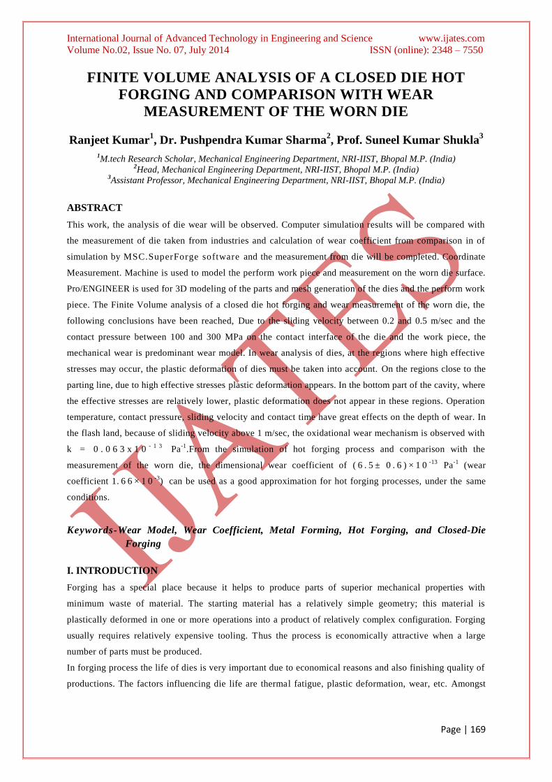
MSC.SuperForge provides elastic-plastic models for work piece material, for dies rigid-plastic models are
used. The work piece material is X20Cr13 .Heat Resisting Stainless steel. Figure.8 shows the work piece
stress-strain curve at a constant temperature of 1100oC for three different strain rates.
Fig.8.stress-strain curve at 1100oC and different strain rates
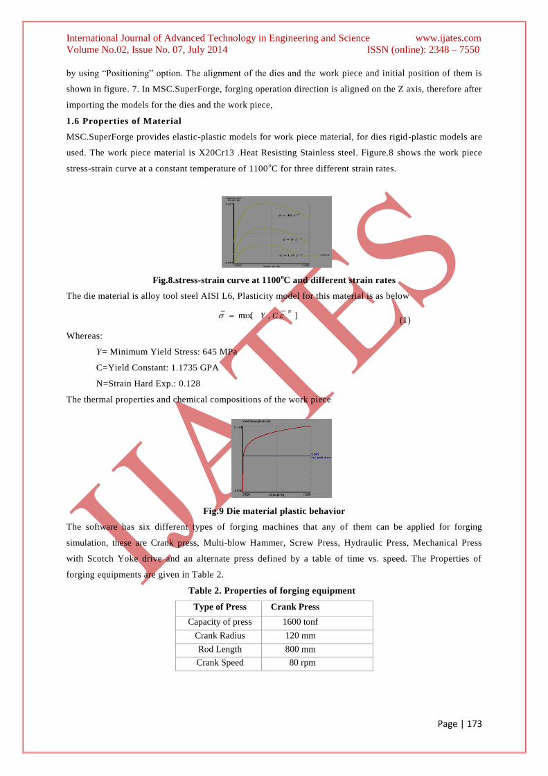
The die material is alloy tool steel AISI L6, Plasticity model for this material is as below
],max[
~ NCY
(1)
Whereas:
Y= Minimum Yield Stress: 645 MPa
C=Yield Constant: 1.1735 GPA
N=Strain Hard Exp.: 0.128
The thermal properties and chemical compositions of the work piece
Fig.9 Die material plastic behavior
The software has six different types of forging machines that any of them can be applied for forging
simulation, these are Crank press, Multi-blow Hammer, Screw Press, Hydraulic Press, Mechanical Press
with Scotch Yoke drive and an alternate press defined by a table of time vs. speed. The Properties of
forging equipments are given in Table 2.
Table 2. Properties of forging equipment
Type of Press Crank Press
Capacity of press 1600 tonf
Crank Radius 120 mm
Rod Length 800 mm
Crank Speed 80 rpm

International Journal of Advanced Technology in Engineering and Science www.ijates.com
Volume No.02, Issue No. 07, July 2014 ISSN (online): 2348 – 7550
Page | 174
With the help of parameter given in Table 2 to the press, the velocity of the crank press can be obtained
during its operation. Figure.9 shows the velocity of press as a function of time. At the beginning and at the
end of press operation the velocity is zero. The maximum velocity of the press is 1.232 m/sec after 0.266
sec of press operation.
Fig.10 The velocity of the crank press as a function of time.
The initial temperatures of work piece and dies have great effect on the simulation of hot forging process as
they influence the plastic behavior of materials. In industry, the dies are generally preheated before using
in hot forging process. The initial temperatures in this study are
Initial temperature of work piece: 1200 oC
Initial temperature of die: 400 oC
Second parameters are used for the simulation:
Heat transfer coefficient
to ambient:
50 watt/m2.K
Heat transfer coefficient to work piece: 6000 watt/m2.K
Emissivity for heat radiation to ambient: 0.25
The die has rough surfaces and is forced to move tangentially with respect to one another, frictional
stresses will develop at the interface. A friction model should be applied to both of the dies. For forging
operations involving relatively low contact pressure between dry contact surfaces. If the frictional shear stress
reaches a critical value, the work piece will slip along the die. According to Coulomb’s law of friction, this
value is given by:
n . (2)
the coefficient of friction and n denotes the normal stress at the work piece-die interface.
The alternative model to Coulomb’s law of friction is Teresa’s friction model, which is the law of plastic
shear friction. According to this model, if the frictional shear stress exceeds a constant fraction m of the
flow stress in shear, yield , the work piece starts to slip.
yieldm . (3)
A value of zero represents perfect sliding, which means there is no shear or friction at the work piece -die
interface. A value of one represents sticking friction, which means that the friction shear stress equals the
flow stress of the material in shear. For forging operations involving relatively high contact pressures, it is
generally more appropriate to use the law of plastic shear friction.
In this work, plastic shear friction model is used as friction model for the simulation. The coefficient of
friction and the interface friction factor assumed as 0.4 and 0.06, respectively.

International Journal of Advanced Technology in Engineering and Science www.ijates.com
Volume No.02, Issue No. 07, July 2014 ISSN (online): 2348 – 7550
Page | 175
1.7 Simulation
In this work, stroke of the operation, size of the finite volume work piece and die element sizes, output step
size, problem type are defined. The suggested problem type for hot forging with flash by MSC.SuperForge
is backward extrusion. In this work this type of problem is selected. A solver optimizer is implemented in
this simulation control unit; thus, the user can change finite volume element size at any time and also
coarsen the work piece to decrease the number of elements. Parameters that are used in this stage are shown
in Table 3 sample view of a completed simulation process can be seen in Figure 12.
Table 3. Operation parameters assigned to complete the simulation.
Problem type Hot forging-closed
die with flash
Initial contact distance 49.20 mm
Flash thickness 5 mm
Upper die displacement 43.20 mm
Work piece element size 2.2 mm
Die element size 2.2 mm
Number of output steps 25
Fig.11 Simulation Performed in MSC.SuperForge
The wear model which is used in MSC.SuperForge is based on Archard’s wear model, offers depth of wear
to be a function of sliding length, hardness, normal stress and wear coefficient. The relation is given by:
H
LPKd
(4)
Where:
d= depth of wear (mm) at each time increment t (s),
K=non-dimensional wear coefficient, P=contact pressure (Pa),
L=sliding distance (mm) at time increment t, H= hardness of die (Pa).
In Equation 4 the sliding distance can be replaced in term of sliding velocity, and value of
H
K
can be replaced by dimensional wear coefficient k Pa-1
.
tUL (5)
H
Kk (6)

International Journal of Advanced Technology in Engineering and Science www.ijates.com
Volume No.02, Issue No. 07, July 2014 ISSN (online): 2348 – 7550
Page | 176
Where:
U= sliding velocity (mm/s) at time increment t, and
K=dimensional wear coefficient (Pa-1
).
Equation 5.4 can be rephrased as:
)..( tUPkd (7)
To obtain final depth of wear for one cycle, Equation 5.7 can be written in summation form of each
increment wear depth,
iii
n
fintUPkd ...
1 (8)
Where:
df i n=Final wear depth at the end of one cycle,
i =Number of increment,
n =Total number of increments that forging is simulated in one cycle.
The value of wear coefficient which is used in MSC.SuperForge to calculate the wear depth is k = 1x 10-12
Pa-1
. Other parameters like contact pressure, sliding velocity, forging operation time and total number of
increments will be calculated by numerical simulation.
II. RESULTS & DISCUSSION OF THE FINITE VOLUME SIMULATION
The Finite Volume simulation of this work by using MSC. Super Forge took about 38 hours to complete
one forging cycle. The operation time of forging, which is obtained from numerical studies, is equal to
7.74×10⁻²
s, total increments for the simulation is 11675. The results can be obtained in output increments
which set to 25;
Fig.12 Perform work piece Fig.13 Result of simulation- finished Product
We are obtaining depth of wear from numerical result; other parameters like contact pressure, sliding
velocity, effective stress, surface temperature and work piece die contact will be used to analyze wear
generation on the die surface. In Figure 12 the velocity of the upper die is shown during the forging
operation. At t = 0, beginning of the forging operation, the work piece and the upper die are in initial
contact. At this moment the velocity of the upper die is about 2 m/sec. At t = 0.077 s the upper die reaches
to its maximum displacement and the forging process will be completed.
Fig. 14 The velocity of the upper die as a function of operation time.

International Journal of Advanced Technology in Engineering and Science www.ijates.com
Volume No.02, Issue No. 07, July 2014 ISSN (online): 2348 – 7550
Page | 177
2.1 Wear Analysis Of The Die
The original die profile form CAD data and the worn die profile measurement by Coordinate Measuring
Machine are shown in figure 13 on one half of the profile. Since wear is result of surfaces contact, surfaces
contact has effect on amount of wear; the process of the die filling in the selected cross section1 is given in
Figure.14 at different stages of the simulation of forging operation. Figure 15 shows cross section 1 of the
die that the result of wear analysis
2.2 Parameters Wear Analysis Affecting
Effect of wear coefficient in wear analysis other parameters like contact pressure, sliding distance, contact
time between die and work piece, and temperature increase on the surface of the die have great effect on
die analysis. Since wear is result of contact between surfaces, the contact pressure and sliding distance
have great effect on wear depth. It is obvious that these parameters have meaning when contact happens
between work pieces and die surface. Then for wear analysis, it is important to study the time that different
points of die are in contact with work piece. Therefore, even some points have high value of contact pressure
and sliding length, but there is a small value of wear. In this case, time of contact must be studied. For
example some point are in contact from the beginning to the end of operation (100% of operation time),
and there are some points, like thin rips, that they come to contact few percentage of operation time, say
20%, then amount of wear would be much higher in first point than second point even during contact there
are higher contact pressure or sliding length at second point. The maximum contact pressure and the
maximum velocity during operation and values in parenthesis, in
a.14% b.35% C.75% d.100%
Fig. 15 Contacts between dies and work piece in different stages. red color shows contact between die and
work piece.
Affects wear is the surface temperature of the die. A high temperature billet is in contact with the die
relatively at lower temperature. Due to large temperature differences, there will be rapid change in the
temperature of die. This change of temperature is cause of two main factors. The final surface temperature
of the die can be obtained from the simulation of hot forging process. In this case study, the highest
temperature is about to 370 oC. Since the initial temperature of die is 300
oC, there is no large increase in
the die temperature.
Fig. 16 Temperature distribution of the die at the end of process time
.

International Journal of Advanced Technology in Engineering and Science www.ijates.com
Volume No.02, Issue No. 07, July 2014 ISSN (online): 2348 – 7550
Page | 178
2.3 Wear Analysis
Cross sections in 2 and 3 will be selected for analysis in the same way as done in the previous sections.
New value of dimensional wear coefficient will be evaluated and by using this new value a modified wear
profile will be compared with the measured worn die profile.
Fig. 17 Section 2 of the die & comparing the original die profile with the worn die profile
( i ) 0 % ( i i ) 4 6 % ( i i i ) 7 4 % ( i v ) 1 0 0 %
Fig. 18 Die filling process in cross section 2. in different time stages of the forging simulation
Wear depth analysis that obtained from forging simulation by Finite Volume Method show that the
maximum value reaches to 6 . 5 × 1 0-3
mm close to the parting line. The minimum depth of wear is about
4 × 1 0-5
mm at the bottom line of the die profile, this area is one of the last spots to be filled during the
forging process with small contact time, therefore the amount of wear is very small due to small contact time,
as shown in Figure 17 after 74% progress of the forging operation time this point would come into contact
with work piece. The values of wear depth at the end of the first forging operation cycle simulation are
shown in Figure 18. The values in parentheses show the wear depth after batch size of 678. By using these
values it is possible to draw wear profile and compare the numerical results with the measurement of the
worn die.
Fig. 19 Wear depth (mm) for k = 1 x 1 0-12
P a-1
in one cycle, in section 2.
Fig.20. Comparison of wear analysis result and the worn die measurement in section 2
We are obtaining good results there should be some evaluation on wear coefficient in order to get
acceptable results compare to measured worn die profile by comparing the result of wear analysis profile
form forging operation simulation with the worn die profile measured,. The largest value is 7 . 7 5 × 1 0-13
at the middle of the profile and the smallest is equal to 0 . 1 1 × 1 0-13
at the bottom line of the profile.
Values of wear coefficient are about 4 × 1 0-13
close to the parting line. The average value of dimensional

International Journal of Advanced Technology in Engineering and Science www.ijates.com
Volume No.02, Issue No. 07, July 2014 ISSN (online): 2348 – 7550
Page | 179
wear coefficient in different points is equal to 6 . 6 5 × 1 0-13
. By using this average value of the wear
coefficient it is possible to calculate new depth of wear at points and new profile can be obtained.
In this work, the wear analysis has been done for a hot forging finishing die, provided by Amtex Auto Ltd.
FVM was used to simulate the hot forging process. The die wear option of MSC.SuperForge was used to
obtain wear depth of the die. The parameters affecting the wear like contact pressure, sliding velocities,
plastic deformation, surface temperature and etc, were obtained from numerical results of the forging
simulation.
The mechanical press with capacity of 1500 tons was used for the forging. During the forging operation,
after 94% of the operation time ( )103.62
t of operation, the effective stresses reach to their
maximum value in the die through the forging process. The maximum effective stress is close to 700 MPa.
By reaching to this value, plastic deformation occurs in the die due to high effective stress and also fatigue
due to the repetitive forging processes in a batch. Both wear and the plastic deformation of the die would be
studied at the points of the die with high effective stress.
The highest value of normal contact pressure appears at about 80% of the operation time on the top flat
surface of the die with a value of 243 MPa. The contact pressure is about 250 MPa on the round corners.
On the flash land, the normal contact pressure is about 200 MPa. The maximum sliding velocity occurs in
flash land, reaches to about 1.6 m/sec. In the cavity, the sliding velocity is about 0.5 m/sec and in narrow
sections it is about 0.3 m/sec which are much smaller than the sliding velocity in the flash land.For the wear
analysis, the flash land and three different sections, where large depth of wear was observed, were chosen and
the wear coefficients in these sections were evaluated. In this study, dimensional wear coefficient k )(H
Kwas
used for the simulation. Using of the dimensional wear H coefficient has advantages due to the fact that the
changes of the non-dimensional wear coefficient and hardness of the die would be taken to account at the same
time as one parameter. It has been observed that by using constant initial value of dimensional wear
coefficient of 10-12
Pa-1
, the die wear simulation results did not show good agreement with the worn die
measurement. For this reason, some evaluation seems necessary to be done on the dimensional wear
coefficient. By knowing the depth of wear from the worn die measurement and by obtaining contact
pressures and sliding velocities from Finite Volume simulation of the hot forging operation, the wear
coefficients have been evaluated for different points. For each section an evaluated value of the
dimensional wear coefficient was obtained. These were 6. 4 8 × 1 0-13
, 5 . 7 5 × 1 0-13
and 4 . 9 6 × 1 0-13
Pa-1
, respectively. The wear profiles obtained from the evaluated wear coefficients have shown better result
than the constant wear coefficient of 1× 10-12
Pa-1
.The differences of the dimensional wear coefficient in
different sections are due to variation in contact pressure and sliding velocity at surface points of the die in
different sections. In section 1, the contact pressure and the sliding velocity is relatively higher than other
sections, therefore higher value of the dimensional wear coefficient is obtained. It is obvious that at high
temperatures, the hardness of die decreases. The temperature of the die surface during the hot forging
operation of this study varies between 400oC and 490
oC. The Hardness of the die material at this range of
temperatures varies between 48 HRC indentation hardness, H , is the average compression stress giving
local plastic deformation on the surface) and 47 HRC (H 3× S y 3750 MPa). By considering hardness of

International Journal of Advanced Technology in Engineering and Science www.ijates.com
Volume No.02, Issue No. 07, July 2014 ISSN (online): 2348 – 7550
Page | 180
4100 MPa for the die material and the Corresponding dimensional wear coefficient equal to 5.5×10⁻¹³
Pa-
1, the Non-dimensional wear coefficient would be obtained as 1.66×10
-3.
By using the value of 4100 MPa for the hardness of the die material, and the range of 150 MPa and 350
MPa for contact pressure on the die, the normalized contact pressureH
P would be obtained between
1.25×10⁻²
and 5.75×10⁻²
during the forging operation; the sliding velocity varies between 0.1 and 0.5
m/sec. Therefore the normalized sliding velocity ).(
nomA
a
Uei would obtain between 5 and 100.
Higher values of wear coefficient are obtained from the hot forging experiments. It can be observed that
the values of wear coefficients obtained in this thesis are higher than the values given as per literature
survey. The reasons are due to difference of temperature and the sliding velocity in hot forging operation
compare to pin-on-disc wear test conditions.
As per other work for wear analysis of warm forging dies, the value of non-dimensional wear coefficient
obtained about 1.510-4
. the different materials other than the considered in the thesis were used for dies
and forging in R. S. Lee, J. L. Jou, “Application of numerical simulation for wear analysis of warm forging
die”, J. Mater. Process. Technol., 2003.it has also effective on these results . As sliding velocity exceeds of
about 1 m/sec, the tips of asperities would be oxidized, and oxidation wear mechanism would occur. Since
the sliding velocity is much higher than 1 m/sec on the flash land of the tested die, oxidation wear mechanism
applies in this area. For the oxidation wear mechanism a non-dimensional wear coefficient of 1 . 1 9 × 1 0-13
Pa-1
was evaluated.
III. CONCLUSION
The Finite Volume analysis of a closed die hot forging and wear measurement of the worn die, the
following conclusions have been reached, Due to the sliding velocity between 0.2 and 0.5 m/sec and the
contact pressure between 100 and 300 MPa on the contact interface of the die and the Work piece, the
mechanical wear is predominant wear model. In wear analysis of dies, at the regions where hi gh effective
stresses may occur, the plastic deformation of dies must be taken into account. On the regions close to the
parting line, due to high effective stresses plastic deformation appears. In the bottom part of the cavity, where
the effective stresses are relatively lower, plastic deformation does not appear in these regions. Operation
temperature, contact pressure, sliding velocity and contact time have great effects on the depth of wear. In
the flash land, because of sliding velocity above 1 m/sec, the oxidation wear mechanism is observed with
k = 0 . 0 6 3 x 1 0- 1 3
Pa-1
.From the simulation of hot forging process and comparison with the
measurement of the worn die, the dimensional wear coefficient of ( 6 . 5 ± 0 . 6 ) × 1 0-13
Pa-1
(wear
coefficient 1. 6 6 × 1 0-3
) can be used as a good approximation for hot forging processes, under the same
conditions.
REFERENCES
[1]J.F. Archard, “Contact and rubbing of flat surfaces”, J. Appl. Phys. Vol.24 PAGE NO.981, 1953.
[2 ] A.N. Bruchanow, A. W. Rebelski, “Gesenkschmieden und Warmpressen”, Verlag Technik, Berlin, 1955.
[3]J.F. Archard, W. Hirst, “The wear of metals under unlubricated conditions”, Proc. R. Soc.,Ser A Vol. 236, PAGE NO. 397–
410,1956
[4]M. M. Kruschov, “Resistance of metals to wear by abrasion, as related to hardn ess”, Proc. of Conf. on Lub. and Wear. Inst. of
Mech. Engrs, London, PAGE NO. 655-59, 1957.

International Journal of Advanced Technology in Engineering and Science www.ijates.com
Volume No.02, Issue No. 07, July 2014 ISSN (online): 2348 – 7550
Page | 181
[5]J,R.Sabroff, F.W. Boulger, H. J. Henning, “Forging Materials and Practices”, Batelle Memorial Institute Columbus Ohio,Vol.37,
PAGE NO. 908-919,1968.
[6] K. Nakajima and Y. Mizutani, “structural change of the surface layer of low carbon steels due to abrading”, Wear Vol.13, PAGE
NO. 283,1969.
[7]Metals Handbook – Forging and Casting”, Vol.5, 8th Edition, ASM Handbook Committee, USA, 1971.
[8 ] T. Altan, H. J. Henning, “Closed-Die Forging of Round Shapes – Flash Design and Material Savings”, Metallurgia and
Metalforming, March, Vol.37,PAGE NO. 83, 1972.
[9] T. Altan, F. W. Boulger, J. R. Becker, N. Akgerman, H. J. Henning, “Forging Equipment,Materials and Practices”, Batelle
Columbus Laboratories Metalworking Division, Ohio, 1973.
[10]T. F. J. Quinn, J.L. Sullivan and D. M. Rowson, “Origins and development of oxidational wear at low ambient temperature”,
Wear Vol.94,PAGE NO. 175, 1984.
[11]S. C. Lim, M. F. Ashby, “Wear mechanism maps”, Acta Metallurgica, Vol.35, PAGE NO. 1-24, 1987
[12]E. Alper, “Computer Aided Design of Axi-Symmetric Press Forgings”, M. Sc. Thesis, Middle East Technical University,
Ankara, Turkey, 1989.
[13] L. Cser, M. Geiger, K. Lange, “Tool life and tool quality in bulk metal forming”, Proc. Inst. Mech. Engrs. Vol. 207, PAGE NO.
223-239, 1993.
[14] A. Bramley; Forging Modelling. Proc. of the 9th Intern. Cold Forging Congress, PAGE NO. 165 - 168, 1995.
[15] A. E. Tekkaya, “Current State and Future Developments in the Simulation of Forming Processes”. Proc. 30th Plenary Meeting
of the International Cold Forging Croup ICFG, Den Bosch, PAGE NO. 1-10,1997.
[16]D. Elmaskaya, “Finite Element Analysis of Effects of Tapered Preforms in Cold Upsetting”, M. Sc. Thesis, Middle East
Technical University, Ankara, Turkey, 1997.
[17]J.A. Williams, Engineering Tribology, Oxford University Press, ISBN 0 19 856503 PAGE NO.8,1998.
[18] J.H. Kang, I.W. Park, J.S. Jae, S.S. Kang, “A study on a die wear model considering thermal softening (I): construction of
the wear model”, J. Mater. Process. Technol. Vol.96 PAGE NO. 53–58,1999
[19]P. Ding, D. Ju, T. Inoue, E. Vries, “Numerical Simulation of Forging and Subsequent Heat Treatment of a Rod by a Finite
Volume Method”, ACTA Metallurgica Sinica (English Letters), Vol.13,PAGE NO. 270 -280, February, 2000.
[20]V. Bhavin Mehta, Ibrahim Al-Zkeri, Jay S. Gunasekera, “Evaluation of MSC.SuperForge for 3D Simulation of Streamlined
and Shear Extrusion Dies”, Ohio University, Athens, Ohio, USA,2000.