finite element modelling and analysis of trans-tibial
TRANSCRIPT

Global Journal of Researches in Engineering: A Mechanical and Mechanics Engineering Volume 14 Issue 4 Version 1.0 Year 2014 Type: Double Blind Peer Reviewed International Research Journal Publisher: Global Journals Inc. (USA) Online ISSN:2249-4596Print ISSN:0975-5861
Finite Element Modelling and Analysis of Trans-Tibial Prosthetic Socket
By Imran Ali, Ramesh Kumar & Yogendra Singh ISM Dhanbad, India
Abstract- The intention of this paper was to analyze prosthetic socket of distinct materials and for different geometry for optimum design solution by finite element analysis. A modified three-dimensional finite element model of the patellar tendon-bearing (PTB) socket was developed in workbench of ANSYS 14.0 to find out the stress distribution and deformation pattern under functionally appropriate loading condition during normal gait cycle. All essential materials used in the analysis were assumed to be homogeneous, linearly elastic and isotropic. A variety of materials were used for the analysis of the socket like Polypropylene, Composite,90/10 PP/PE, HDPE and LDPE. Analysis was done on a various thickness of socket and of different length along with of different materials commonly applied in developing countries. For boundry condition, fixed support was applied to the distal end of the socket and vertical loads were applied under static condition at pattelar tendon-brim, medial tibia, lateral tibia and popliteal area during stance phase of gate cycle.
Keywords: patellar tendon-bearing (ptb), trans-tibial (tt) prosthesis, finite element (fe) model,
socket/stump interface stress.
GJRE-A Classification : FOR Code: 290501
FiniteElementModellingandAnalysisofTrans-TibialProstheticSocket
Strictly as per the compliance and regulations of:
© 2014. Imran Ali, Ramesh Kumar & Yogendra Singh. This is a research/review paper, distributed under the terms of the Creative Commons Attribution-Noncommercial 3.0 Unported License http://creativecommons.org/licenses/by-nc/3.0/), permitting all non commercial use, distribution, and reproduction inany medium, provided the original work is properly cited.

Finite Element Modelling and Analysis of Trans-Tibial Prosthetic Socket
Imran Ali α, Ramesh Kumar
σ & Yogendra Singh
ρ
Abstract- The intention of this paper was to analyze prosthetic socket of distinct materials and for different geometry for optimum design solution by finite element analysis. A modified three-dimensional finite element model of the patellar tendon-bearing (PTB) socket was developed in workbench of ANSYS 14.0 to find out the stress distribution and deformation pattern under functionally appropriate loading condition during normal gait cycle. All essential materials used in the analysis were assumed to be homogeneous, linearly elastic and isotropic. A variety of materials were used for the analysis of the socket like Polypropylene, Composite,90/10 PP/PE, HDPE and LDPE. Analysis was done on a various thickness of socket and of different length along with of different materials commonly applied in developing countries. For boundry condition, fixed support was applied to the distal end of the socket and vertical loads were applied under static condition at pattelar tendon-brim, medial tibia, lateral tibia and popliteal area during stance phase of gate cycle. Keywords: patellar tendon-bearing (ptb), trans-tibial (tt) prosthesis, finite element (fe) model, socket/stump interface stress.
I. Introduction
he socket is a basic component for prosthetic performance. Below-knee amputees generally demonstrate some gait abnormalities such as
lower walking speed [1], incresed energy cost [2], and asymmetries between legs of unilateral amputees in stance phase cycle, step length and maximum vertical force [3]. Successful fitment of prosthesis may be achieved by understanding the biomechanical structure of socket and its material, weight, thickness in particular to fulfill the desirable load distribution in soft tissues and bone of residual limb. Most commonly used socket design in developing countries is pattelar tendon bearing (PTB) socket developed following the World War II at the University of California, Berkeley in the late 1950 s [4,5]. The Finite Element Method (FEM) has been used widely in biomechanics to obtain stress, strain and deformation in complicated systems and have been identified as an important tool in analysing load transfer in prosthesis [6]. The finite element analysis (FEA) models have been used to study the effects of the inertial loads and contact conditions on the interface between prosthetic socket and stump of an amputee Author α σ ρ: M Tech, Mechanical Engineering Dept., ISM Dhanbad, India. e-mails: [email protected], [email protected], [email protected]
during gait cycle [7,8].The finite element methode has been used as a tool for parametric study and evaluation of prosthetic socket[9,10].
It is common for amputees to experience pain and discomfort in the residual limb while wearing the prosthetic socket [11]. For a lower limb amputee, the comfortableness of wearing prosthesis depends on the distribution of stress at the interface of residual limb and prosthetic socket is either at the pressure-tolerant (PT) or pressure-relief (PR) areas. By employing the technology of computer-aided engineering, the quality uncertainty and labour intensity of traditional process of fabricating a prosthetic socket can be improved. Lower limb prosthesis allows ambulation and improves the performance of daily routine activities. However, poor-fitted socket can lead to complications that have adverse effects on the activity level and gait cycle of people with lower limb amputation [12].
The interface between the stump of lower limb amputees and their prostheses is the prosthetic socket. The contact pressure at the residual limb and prosthetic socket interface is an essential index, and is considered as a promising measure towards good socket design. Therefore, the fundamental concern is to understand pressure distribution at the stump-socket interface. Although the use of pressure sensor is a direct experimental approach towards estimating interface pressure, the analytical approach is an alternating to the experimental one, and finite element modeling of the socket has been used to analyse the contact pressure. Although, the complex features of the soft limb tissues and of their interaction with the socket still remains difficult to model [13].
The variation of interface pressure between the stump and socket is an important factor in socket design and fit. Lower limb prosthetic socket users experience pressure between the stump and socket during daily routine activities. The underlying soft tissues and skin of the stump are not habitual to weight bearing; thus, there is the risk of degenerative tissue ulcer in the stump because of cyclic or constant peak pressure applied by the prosthetic socket [14]. The pressure also can lead to various skin deases such as follicular hyperkeratosis, allergic contact dermatitis, infection and veracious hyperplasia [15-17].
Despite significant scrutiny in the field of prosthetics in the previous decades, still many
T
© 2014 Global Journals Inc. (US)
Globa
l Jo
urna
l of
Resea
rche
s in E
nginee
ring
()
AVol
43
Year
2014
ume
XIV
Issu
e IV
Version
I

amputees experience pressure ulcers with the use of prostheses. Sometimes, skin problems lead to chronic infection, which may necessitate re-amputation. This will obviate the long-term use of prosthesis, which indicatively reduces the routine activities of prosthesis users and the quality of life [18]. Many studies have concentrated on interface pressure magnitude between the socket and stump during level walking [19-20].
a) Trans-Tibialprosthesis Description The artificial limb consists of a foot-ankle unit
which needs to be attached to the remainder of the amputee's natural leg or stump. The foot ankle unit is attached directly to the socket frame. The artificial shank can be attached to the foot ankle unit and then attached to the socket frame for a below-knee amputation. Today the sockets are roughly quadrilateral in shape. They attempt to have total contact between the stump and the socket.
II. Finite Element Model
A frequently used numerical analysis technique in biomechanics is the finite element technique, a computational approach for interface stress or structural deformation calculation evoluted in engineering mechanics. It has been introduces as a useful tool to understand the load transfer mechanics between a residual limb and its prosthetic socket. The finite element technique is a full-field analysis for calculating the state of stress and elestic strain in the specific field. This technique is well suited for parametric analysis in the process of design. The previous finite element analyses showed the significance of considering prestress in predicting interface stresses at loading stage[21-22].
One left unilateral male trans-tibial amputee participated in this study. The volunteer was 45 years of age, 166 cm tall, 70 kg in mass, and the cause of his amputation was an accident. He has been an active amputee for five years, using his prosthetic limb for all his daily chores. The simplified geometry of his residual limb was modeled in Pro-engineer and then it is being imported (in IGES formate) and modified in ANSYS 14.0 Workbench.
The finite element model was kept as simple as possible in terms of material properties and boundary conditions. Different materials for 2 mm, 3 mm, 4 mm, 5 mm, and 6 mm unit volume layer thickness was used for creating the 3-D FE model. Also the three dimension finite element model is developed for varrying the length of the socket of 16 cm, 17 cm, 18 cm, 19 cm, 20 cm, 21 cm. The model was meshed with brick element solid 185 with fused tibia and fibula bones. A total of 41,073 elements and 20,438 nodes were used.
Table 1 : Properties of different socket material
Table 2 :
Stance phase and Maximum vertical ground
© 2014 Global Journals Inc. (US)
Globa
l Jo
urna
l of
Resea
rche
s in E
nginee
ring
(
)A
Vol
44
Year
2014
ume
XIV
Issu
e IV
Version
I
Finite Element Modelling and Analysis of Trans-Tibial Prosthetic Socket
Material YM (MPa)
Density (Kg/m3)
US (MPa)
PR
Composite 1,600 1194 144 0.39Polypropylene 1,100 910 80 0.37
PP/PE 1,500 830 39 0.3HDPE 800 950 37 0.40LDPE 280 920 25 0.41
Five phases of stance
Percentage Variation of
GRF(N)
Maximum GRF(N)
Initial Contact/Heel Strike (HS)
(0-13)% 0-620 620
Foot Flat/Loading Response
(LR)
(13-38)% 620-1000 1000
Mid-Stance (MS)
(38-63)% 510-707 707
Terminal Stance/Heel
Off (HO)
(63-88)% 630-1000 1000
Pre-Swing/Toe Off (TO)
(88-100)% 0-810 810
IV. Results
The results for total deformation, shear stress and equivalent von-Mises stress of developed and modified transtibial socket model were obtained by using (ANSYS Workbench v14.0) program. Figure (1) shows the meshed view of the finite element three dimension socket model, and figure (2) shows the maximum von-Mises stress developed for different loading conditions of stance phase like Initial
On the meshed model fixed support is being applied at the distal end of the socket, distal end of the socket is further attached with the remaining parts of the
prosthesis like shank, ankle foot. The different loading conditions as listed in table 2 were quasi-static approximations using experimentally obtained maximum vertical ground reaction for the prosthetic side of same subject while walking at a given speed using CGD gait cycle analyzer [24-27].
III. Material Properties
In this analysis the different material used are composite, polypropylene, 90/10 PP/PE (90% polypropylene and 10% ethylene), high density polyethylene (HDPE) and low density polyethylene (LDPE). The mechanical properties of the socket material were assumed to be linearly elastic, isotropic and homogeneous. Socket were analyzed for different materials and their valus of Young’s modulus, Ultimate strength, Poisson’s ratio and density is listed in table 1.

© 2014 Global Journals Inc. (US)
Globa
l Jo
urna
l of
Resea
rche
s in E
nginee
ring
()
AVol
45
Year
2014
ume
XIV
Issu
e IV
Version
I
Finite Element Modelling and Analysis of Trans-Tibial Prosthetic Socket
Contact/Heel Strike (HS), Foot Flat/Loading Response (LR), Mid-Stance (MS), Terminal Stance/Heel Off (HO) and Pre-Swing/Toe Off (TO).
Figure 1 : Meshed view Figure 2 : Equivalent von-Mises stress at different stance
Figure 3 : shows the shear stress and figure (4) shows the total deformation developed for different loading conditions like Initial Contact/Heel Strike (HS), Foot Flat/Loading Response (LR), Mid-Stance (MS), Terminal
Stance/Heel Off (HO) and Pre-Swing/Toe Off (TO) of stance phase
The maximum values of von-Mises stress, shear stress and total deformation occure in five phases of stance under the load of 1000 N are listed in the table 3 as shown below.
Table 3 : von-Mises stress, Shear stress and Total deformation at different phases of stance at 1000 N of
load
Stance phase von-Mises stress (MPa)
Shear stress (MPa)
Total deformation
(mm)
Initial Contact/Heel Strike (HS)
6.55 1.02 0.55
Foot Flat/Loading Response (LR)
10.54 1.64 0.88
Mid-Stance (MS) 7.45 1.16 0.63Terminal
Stance/Heel Off (HO)
10.54 1.64 0.88
Pre-Swing/Toe Off (TO) of stance
phase
8.54 1.33 0.72
Figure 3 : Shear Stress

© 2014 Global Journals Inc. (US)
Globa
l Jo
urna
l of
Resea
rche
s in E
nginee
ring
(
)A
Vol
46
Year
2014
ume
XIV
Issu
e IV
Version
I
Finite Element Modelling and Analysis of Trans-Tibial Prosthetic Socket
Figure 4 : Total deformation
Different approaches have been used to analyzed for socket material and thickness optimization:
a) Socket thickness vs Factor of safetyFor different thickness of composite,
polypropylene (PP), 90/10 PP/PE, HDPE and LDPE materials the weight of the socket were calculated and listed in table 4.
b) Tsai-Hill Criterion for socket failureSocket failure is analyzed by Tsai-Hill Criterion
based on maximum distortion criterion and used in this analysis to compare socket failure [23].
Tsai-Hill Criterion, CTH = 𝜎𝜎12
𝑆𝑆𝑣𝑣2− 𝜎𝜎1∗𝜎𝜎2
𝑆𝑆𝑣𝑣2+ 𝜎𝜎2
2
𝑆𝑆𝑡𝑡2 + 𝜏𝜏2
𝑆𝑆𝑠𝑠ℎ2
Where CTH is the Tsai-Hill failure coefficient, Sv, St and Ssh are the ultimate strengths of composite in the vertical, transverse and shear directions respectively listed in table 5 and σ1, σ2 and τ are the imposed stresses in the longitudinal, transverse, and shear planes. If the value of CTH is less than one than design is safe.
Table 4 : Weight of socket in grams [30]
Thickness(mm)
Composite PP PP/PE
HDPE
LDPE
23456
140209280350420
106160212266320
102155208261315
111168214278334
107174222269323
Table 5 : Tensile and compressive strength of composite [31]
c) Structural Behavior vs LengthThe values of maximum von-Mises stress, shear
stress and total deformation off all the material in different length were analyzed and shown in figures 11-13, and it is found that as the length of socket increses the values of stress and deformation decreases. The decrease in value of deformation as increase of length is higher in case of LDPE material.
d) Structural Behavior vs ThicknessThe values of maximum von-Mises stress, shear
stress and total deformation off all the material in different thickness were analyzed and shown in figures 8-10, and it is found that as the thickness of socket increses the values of stress and deformation decreases. The decrease in value of deformation as increase of thickness is higher in case of LDPE material.
Strength (in MPa)
Sv St Ssh
Tension 584 43 44
Compression 803 187 64

© 2014 Global Journals Inc. (US)
Globa
l Jo
urna
l of
Resea
rche
s in E
nginee
ring
()
AVol
47
Year
2014
ume
XIV
Issu
e IV
Version
I
Finite Element Modelling and Analysis of Trans-Tibial Prosthetic Socket
Figure 5 : Equivalent von-Mises stress at pressure tolerated areas in stance phase of gait cycle during normal walking on plane surface at a given speed
a) Case 1 : Weight of the socketThe variation of factor of safety as a function of
Weight of the socket for a socket of different thickness is shown in figure 7, where factore of safety is being calculeted by dividing maximum von-Mises stress at a load of 620 N with the endurance limit (50% ultimate tensile strength value) [28]. During daily activities of an amputee the total load of knee joint in transtibial prosthesis passes on the prosthetic socket. During normal walking , the total joint reaction forces at knee joint is three to four times increases than the total body weight, during jumping and fast running load on knee joint increses more [29]. Therefore, six factore of safety is minimum desirable to withstand the loading of socket. The factor of safety is just below the level of five for LDPE and HDPE so, it can be suggested that LDPE and HDPE are note suitable for prosthetic socket design.
b) Case 2 : Analysis of failureThe finite element simulation result of rotation
and displacement in different parts of socket validate the biomechanical requirement of structural integrity in patellar tendon bearing socket. Figure 7 shown below describes the variation of Tsai-Hill coefficient with tensile and compressive strength. The value of CTH coefficient in 2mm thick composite for tensile strength is 0.1864wich is only five times factore of safety but thickness between 3 mm (0.0724) to 4 mm (0.031) has a factore of safety more than twenty times. Therefore, the optimum solution of composite material of thickness 3 mm to 4 mm satisfied the Tsai-Hill criterion.
Figure 6 : Weight of socket in reference to Factor of safety
Figure 7 : Tsai-Hill coefficient with 620N load in tension and compression
0
1
2
3
4
5
6
7
8
9
0 20 40 60 80 100
Stre
ss (i
n M
Pa)
%
of stance phase
Patellar TendonMedial TibiaLateral TibiaPopliteal AreaDistal End
0
5
10
15
20
25
30
35
40
0 100 200 300 400 500
Fact
ore
of sa
ftey
Weight of socket (in gram)
CompositePPPP/PEHDPELDPE
0
0.04
0.08
0.12
0.16
0.2
2 3 4 5 6
C TH
Co
effic
ient
Thickness (in mm)
TensionCompression
optimum
V. Discussion

© 2014 Global Journals Inc. (US)
Globa
l Jo
urna
l of
Resea
rche
s in E
nginee
ring
(
)A
Vol
48
Year
2014
ume
XIV
Issu
e IV
Version
I
Finite Element Modelling and Analysis of Trans-Tibial Prosthetic Socket
c) Case 3 : Thickness of the socketIn all materials it is found that the von-Mises
stress, shear stress and total deformation is inversely proportional to thickness except for LDPE of the socket figure 8-10. However the stress and stress variation were higher in case of 2mm and 3 mm socket and it is relatively low in case of 4mm and 6mm. Thus 3 mm to 4 mm could be a optimal solution in terms of thickness of the socket for all materials where this much thickness is used. The variation of von-Mises stress, shear stress and total deformation for different thickness of prosthetic socket were shown in figure 8, 9 and 10 respectively. The value of total deformation in case of LDPE of thickness less than 3 mm goes higher and it may loss biomechanical load bearing ability. Thus the result indicates that the LDPE socket length is not suitable fore fabrication of PTB socket of below 4 mm thickness.
Figure 8 : Equivalent von-Mises stress in different thickness of composite, PP, PP/PE, HDPE and LDPE at
1000 N
Figure 9 : Shear stress in different thickness of composite, PP, PP/PE, HDPE and LDPE at 1000 N
Figure 10 : Total deformation in different thickness of composite, PP, PP/PE, HDPE and LDPE at 1000 N
Figure 11 : Equivalent von-Mises stress in different length of composite, PP, PP/PE, HDPE and LDPE at
1000 N
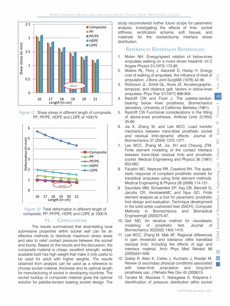
e) Case 4 : Length of the socketIn all materials it is found that the von-Mises
stress, shear stress and total deformation is inversely proportional to length of the socket figure 11-13. However the stress and stress variation were higher in case of 16 and 17 cm length socket and it is relatively low in case of 19cm and 20cm. Thus 19 cm to 20cm could be a viable solution in terms of length of the socket for all materials where this much length is possible. The variation of von-Mises stress, shear stress and total deformation for different length of prosthetic socket were shown in figure 11, 12 and 13 respectively. The value of total deformation in case of LDPE of length less than 16 cm goes higher and it may loss biomechanical load bearing ability. Thus the result indicates that the LDPE socket length is not suitable fore fabrication of PTB socket of below 16cm length.
0
2
4
6
8
10
12
14
16
2 3 4 5 6
von-
Mise
s str
ess (
in M
Pa)
Thickness (in mm)
CompositePPPP/PEHDPELDPE
optimum
0
0.5
1
1.5
2
2.5
3
2 3 4 5 6
Shea
r str
ess (
in m
m)
Thickness (in mm)
Composite
PP
PP/PE
HDPE
LDPE
optimum
0
2
4
6
8
10
12
14
16
2 3 4 5 6
Tota
l def
orm
atio
n (in
mm
)
Thickness (in mm)
LDPE
HDPE
PP/PE
PP
Composite
optimum
0
2
4
6
8
10
12
14
16
16 17 18 19 20 21
von-
Mise
s str
ess (
in M
Pa)
Length (in cm)
CompositePPPP/PEHDPELDPE
optimum
© 2014 Global Journals Inc. (US)
Globa
l Jo
urna
l of
Resea
rche
s in E
nginee
ring
()
AVol
49
Year
2014
ume
XIV
Issu
e IV
Version
I
Finite Element Modelling and Analysis of Trans-Tibial Prosthetic Socket
Figure 12 : Shear stress in different length of composite, PP, PP/PE, HDPE and LDPE at 1000 N
Figure 13 : Total deformation in different length of composite, PP, PP/PE, HDPE and LDPE at 1000 N
VI. ConclusionsThe results summarized that assimilating local
submissive properties within socket wall can be an effective methods to distribute maximum stress areas and also to relief contact pressure between the socket and stump. Based on the results and the discussion, the composite material is cheap, excellent strength, widely available butit has high weight that make it only useful to be used for adult with higher weights. The results obtained from analysis can be used as a reference to choose socket material, thickness and its optimal length for manufacturing of socket in developing countries. The socket buildup of composite material gives the optimal solution for patellar-tendon bearing socket design. The
study reconnoitered further future scope for parametric analysis, investigating the effects of liner, socket stiffness, rectification scheme, soft tissues, and materials for the socket/stump interface stress distribution.
References Références Referencias
1. Molen NH. Energy/speed relation of below-knee amputees walking on a motor-driven treadmill. Int Z Angew Physiol 31(1973) 173-85.
2. Waters RL, Perry J, Aatonelli D, Hislop H. Energy cost of walking of amputees: the influence of level of amputation. J Bone Joint Surg58A (1976) 42-46.
3. Robinson JL, Smidt GL, Arora JS. Accelerographic, temporal, and distance gait: factors in below-knee amputees. Phys Ther 57(1977) 898-904.
4. Radcliff CW and Foort J. The patellar-tendon-bearing below knee prosthesis. Biomechanics laboratory, University of California, Berkeley (1961).
5. Radcliff CW Functional considerations in the fitting of above-knee prostheses. Artificial Limb 2(1955) 35-60.
6. Jia X, Zhang M, and Lee WCC. Load transfer mechanics between trans-tibial prosthetic socket and residual limb-dynamic effects. Journal of Biomechanics 37 (2004) 1372-1377.
7. Lee WCC, Zhang M, Jia, XH and Cheung JTM. Finite element modeling of the contact interface between trans-tibial residual limb and prosthetic socket. Medical Engineering and Physics 26 (1961) 655-662.
8. Faustini MC, Neptune RR, Crawford RH. The quasi-static response of compliant prosthetic sockets for transtibial amputees using finite element methods. Medical Engineering & Physics 28 (2006) 114-121.
9. Saunders MM, Schwentker EP, Kay DB, Bennett G, Jacobs CR, VerstraeteMC and Njus GO. Finite element analysis as a tool for parametric prosthetic foot design and evaluation. Technique development in the solid ankle cushioned heel (SACH). Computer Methods in Biomechanics and Biomedical Engineering6 (2003)75-87.
10. Geil MD. An iterative method for viscoelastic modeling of prosthetic feet. Journal of Biomechanics 35(2002) 1405-1410.
11. Lee WCC, Zhang M, Mak AF. Regional differences in pain threshold and tolerance ofthe transtibial residual limb: Including the effects of age and interface material. Arch Phys Med Rehabil 86 (2005)641-649.
12. Gailey R, Allen K, Cstles J, Kucharic J, Roeder M. Review of secondary physical conditions associated with lower-limb amputation and long-term prosthesis use. J Rehabil Res Dev 45 (2008)15.
13. Tanaka M, Akazawa Y, Nakagawa A, Kitayama I. Identification of pressure distribution atthe socket
0
0.5
1
1.5
2
2.5
16 17 18 19 20 21
Shea
r str
ess (
in m
m)
Length (in cm)
CompositePPPP/PEHDPELDPE
optimum
0
1
2
3
4
5
6
16 17 18 19 20 21
Defo
rmat
ion
(in m
m)
Length (in cm)
CompositePPPP/PEHDPELDPE
optimum

Finite Element Modelling and Analysis of Trans-Tibial Prosthetic Socket
© 2014 Global Journals Inc. (US)
Globa
l Jo
urna
l of
Resea
rche
s in E
nginee
ring
(
)A
Vol
50
Year
2014
ume
XIV
Issu
e IV
Version
I
interface of above-knee prosthesis. Advances in Engineering Software 28 (1997) 379-384
14. Lee WCC, Zhang M, Mak AF. Regional differences in pain threshold and tolerance of the transtibialresidual limb: Including the effects of age and interface material. Arch Phys Med Rehabil 86 (2005) 641-649.
15. LyonCC, Kulkarni J, Zimerson E, Van RossE, Beck MH.Skin disorders in amputees. J Am Acad Dermatol. 42 (2000), 501-507.
16. Dudek NL, Khan OD, Lemaire ED, Marks MB, Saville L, Maffiulletti N. Ambulation monitoring of transtibial amputation subjects with patient activity monitorversus pedometer. J Rehabil Res 45 (2008)577-585.
17. Dudek NL, Marks MB, Marshall SC, Chardon JP.Dermatologic conditions associated with use of lower-extremity prosthesis. Arch Phys Med Rehabil 86 (2005)659-663.
18. AliS, Abu Osman NA, Mortaza N, Eshraghi A, Gholizadeh H, Wan Abas WAB. Clinical investigation of the interface pressure in the trans-tibial socket with Dermo and Seal-In X5 liner during walking and their effect on patient satisfaction. Clinical Biomechanics 27 (2012) 943–948.
19. Convery P, Buis A. Socket/stump interface dynamic pressure distributions recorded during the prosthetic stance phase of gait of a trans-tibial amputee wearing a hydrocast socket. ProsthetOrthot Int 23 (1999)107-112.
20. Silver-Thorn MB, Childress DS. Parametric analysis using the finite element method to investigate prosthetic interface stresses for persons with trans-tibial amputation. J Rehabil Res Dev 33 (1996) 227-238.
21. Lee WCC, Zhang M, Jia XH, Boone DA. A computation model for monolimb design. In: Proceedings of the International Society of Biomechanics Dunedin, New Zealand (2003) 234.
22. Lee WCC, Zhang M, Jia XH, Cheung JTM. FE modeling of the load transfer between trans-tibial residual limb and prosthetic socket. Med Engg Phys. 26 (2004) 655–662.
23. Hahl J, Taya M. Experimental and numerical predictions of the ultimete strength of a low-cost composite transtibial prosthesis. Journal of Rehabilitation Research and Development 37 (2000) 405-413.
24. Kalen V, Adler N, Bleck EE. Electromyography of idiopathic toe walking. Journal of Pediatric Orthopedics, 6 (1986) 31-33.
25. LyonsK, Perry J, Gronley J, Barnes L, Antonelli D. Timing and relative intensity of hip extensor and abductor muscle action during level and stair ambulation: an EMG Study. Journal of the American Physical Therapy Association 63(1983) 1597-1605.
26. Mann RA, Inman VT. Phasic activity of intrinsic muscles of the foot. Journal of Bone and Joint Surgery 46(1964) 469-481.
27. Moxham J, Edwards RHT, Aubier M, DeTroyer A, Farkas G, Macklem PT, Roussos C. Changes in EMG power spectrum (high-to-low ratio) with force fatigue in humans. Journal of Applied Physiology 53(1982) 1094-1099.
28. Gibson RF. Principles of composite materials mechanics. McGraw-Hill, New York (1994).
29. Hamill J, Knutzen. Biomechanical basis of human movement. 2nd Edition William & Wilkins Publisher, Philadelphia 237(1961).
30. Lenka PK, Choudhury AR. Analysis of transtibial prosthetic socket materials using finite element method. J. Biomedical Science and Engineering 4 (2011) 762-768.
31. Silver-Thron MB. Prediction and experimental verification of residual limb/prosthetic socket interface pressure for below knee amputees. North-western University, Evanstoon (1991).