finite element modelling analysis on built-up …umpir.ump.edu.my/id/eprint/12233/13/finite element...
TRANSCRIPT

FINITE ELEMENT MODELLING ANALYSIS ON BUILT-UP COLUMN
CANDRA MENAN NAGAPPAN
This thesis is submitted in partial fulfilment of the requirement
for the award of the degree of
B.Eng (Hons.) Civil Engineering
Faculty of Civil Engineering and Earth Resources
UNIVERSITI MALAYSIA PAHANG
JUNE 2015

vi
ABSTRACT
Build-up column is a steel structure composed of two I-beam steel joined with steel
plate or angles as the lacings of the column. The build-up column is one of the main
load carrying members among all the other structural components of a building. Since
the build-up column is assembled manually at the construction site, there might have
some error in the section and orientation of the lacings assembled which will affect the
performance of the build-up column. The main objectives of this study the effect of the
different section and orientation of steel elements on build-up column in terms of
buckling and stress distribution. Finite Element Analysis of Ansys 12.0 software is used
to design the ten model of the build-up column. In order to study the effect of section of
lacings, steel plate and L-angles are used. Besides that, to study the effect of orientation
of the lacings, inclination angles of 40° , 45
°, 50
° , 55
° and 60
° are used. Based on the
results, orientation of the steel lacings influenced the stress distribution of the due to the
load. The greater the inclination angle the smaller the stress builds up on the lacings.
Thus, the build-up column is more stable.
Keywords: Built-up column, Chord, Lacings, Stress Distribution, Buckling, Ansys,
Finite Element Modeling, Orientation, Section

vii
ABSTRAK
Tiang "built-up" adalah satu struktur keluli terdiri daripada dua I-rasuk keluli bergabung
dengan plat keluli atau sudut sebagai penyusun ikatan tiang. Tiang "built-up" adalah
salah satu ahli yang menanggung beban kesemua ahli-ahli lain di kalangan semua
komponen struktur lain bangunan. Sejak tiang "built-up" yang dipasang secara manual
di tapak pembinaan, mungkin mempunyai beberapa kesilapan dalam penggunaan keluli
penyusun ikatan tiang berbeza dan orientasi penyusun ikatan dipasang yang akan
memberi kesan kepada prestasi tiang "built-up". Objektif utama kajian ini kesan seksyen
yang berbeza dan orientasi elemen keluli pada ruangan membina-up dari segi lengkokan
dan pengagihan tekanan. Analisis Unsur Terhingga perisian ANSYS 12.0 digunakan
untuk mereka bentuk model sepuluh tiang "built-up". Untuk mengkaji kesan bahagian
penyusun ikatan, plat keluli dan L-sudut digunakan. Di samping itu, untuk mengkaji
kesan orientasi penyusun ikatan, sudut kecondongan 40 °, 45 °, 50 °, 55 ° dan 60 °
digunakan. Berdasarkan kepada keputusan, orientasi penyusun ikatan keluli
mempengaruhi taburan tekanan daripada kerana beban. Lebih besar sudut
kecenderungan yang lebih kecil tekanan yang membina pada penyusun ikatan. Oleh itu,
ruang membina-up adalah lebih stabil.
Kata Kunci: Tiang, I-Rasuk, Penyusun Ikatan Tiang, Beban, Tekanan, Orientasi, Ansys

viii
TABLE OF CONTENTS
Page
SUPERVISOR’S DECLARATION ii
STUDENTS DECLARATION iii
ACKNOWLEDGEMENT v
ABSTRACT vi
ABSTRAK vii
TABLE OF CONTENTS viii
LIST OF TABLES xi
LIST OF FIGURES xii
CHAPTER 1 INTRODUCTION
1.1 Background of study 1
1.2 Problem Statement 2
1.3 Objective of The Study 3
1.4 Scope of Study 3
1.5 Significance of Study 6
CHAPTER 2 LITERATURE REVIEW
2.1 Introduction 7
2.2 Material 8
2.3 Lacing types 9
2.4 Load and Connections 10
2.5 Experiment and FEM Analysis 10

ix
2.6 Guidelines Related to Eurode 3 14
2.7 Important Studies 15
CHAPTER 3 METHODOLOGY
3.1 Introduction 17
3.2 Research Methodology Flowchart 18
3.3 Methodology 19
3.3.1 Material Properties 19
3.3.2 Modeling 26
3.3.3 Coordination of Column 27
3.3.4 Application of Load and Boundary Conditions 35
3.3.5 Results 37
CHAPTER 4 RESULTS AND DISCUSSIONS
4.1 Introduction 39
4.2 Stress Distribution 39
4.2.1 Stress Distribution of Built-up Column with
Plate Lacings
40
4.2.2 Stress Distribution of Built-up Column with
Angle Lacings
51
4.2.3 Comparison of Stress Distribution Between
Plate
and Angle lacings
61
4.3 Buckling 62
4.3.1 Buckling of Built-up column with Plate
Lacings
63
4.3.2 Buckling of Built-up column with Angle
Lacings
72
4.3.3 Comparison of buckling Between Plate and
Angle Lacings
81

x
CHAPTER 5 CONCLUSION AND RECOMMENDATIONS
5.1 Introduction 82
5.2 Conclusion 82
5.3 Recommendations 83
REFERENCES 84

xi
LIST OF TABLES
TABLE NO. TITLE
PAGE
1.1 Property table for the built-up column models 5
4.1 Stress Distribution of Lacings and Chord ( Plate ) 49
4.2 Comparison of Stress on Chord ( Plate ) 50
4.3 Comparison of Stress on Lacings ( Plate ) 55
4.4 Stress Distribution of Lacings and Chord ( Angle ) 60
4.5 Comparison of Stress on Chord ( Angle ) 61
4.6 Comparison of Stress on Lacings ( Angle ) 61
4.7 Comparison of Stress on Chord for All the Column Model 62
4.8 Buckling of Plate Lacings and Chord 71
4.9 Buckling of Angle Lacings and Chord 80
4.10 Comparison Buckling Between Different Section of
Lacings
81

xii
LIST OF FIGURES
FIGURE NO TITLE
PAGE
1.1 Components of the built-up column 4
3.1 Activation of Civil Setup and set units 20
3.2 Selection of element type 21
3.3 Material selection 21
3.4 Specifications of I-beam 22
3.5 Specifications of cross sections ( Steel Plate) 22
3.6 Steel plate cross sections 23
3.7 Specify member properties 23
3.8 Details of the member properties specifications 24
3.9 Beam and shell properties 24
3.10 Beam property 25
3.11 Details of the specifications 25
3.12 Section properties ( I-beam ) 26
3.13 Section properties ( Steel plate / angles ) 26
3.14 Creating the nodes for elements 27
3.15 Copy and paste coordinates of node from notepad to
command box
27
3.16 Element attributes before the plotting of element 28
3.17 Plotting of elements ( I-beam ) 28
3.18 Element attributes for second member 29
3.19 Plotting of element for second member ( Plate / angles ) 29
3.20 Contact pair 30
3.21 Choosing the target surface node 30
3.22 Save the target surface 31

xiii
3.23 Pick contact node 31
3.24 Selecting contact surface node 32
3.25 Click Next to save and proceed to next step 32
3.26 Setting the boundary condition of contact pair 33
3.27 Finishing the contact pair process 33
3.28 Plotting the contact pair 34
3.29 Contact pair created on the plane 34
3.30 Check the connection status 35
3.31 Choosing the nodes to apply the boundary conditions 35
3.32 Applying the relevant boundary conditions to the selected
nodes
36
3.33 Node selection to apply the load 36
3.34 Determining the force direction 37
3.35 Analysis of the model 37
3.36 Analysis done successfully 38
4.1 Stress Distribution of VLC 1 with 10kN Axial Load 40
4.2 Stress Distribution of VLC 2 with 10kN Axial Load 41
4.3 Stress Distribution of VLC 3 with 10kN Axial Load 41
4.4 Stress Distribution of VLC 4 with 10kN Axial Load 42
4.5 Stress Distribution of VLC 5 with 10kN Axial Load 42
4.6 Stress Distribution of VLC 1 with 100kN Axial Load 43
4.7 Stress Distribution of VLC 2 with 100kN Axial Load 43
4.8 Stress Distribution of VLC 3 with 100kN Axial Load 44
4.9 Stress Distribution of VLC 4 with 100kN Axial Load 44
4.10 Stress Distribution of VLC 5 with 100kN Axial Load 45
4.11 Stress Distribution of VLC 1 with 1000kN Axial Load 45

xiv
4.12 Stress Distribution of VLC 2 with 1000kN Axial Load 46
4.13 Stress Distribution of VLC 3 with 1000kN Axial Load 46
4.14 Stress Distribution of VLC 4 with 1000kN Axial Load 47
4.15 Stress Distribution of VLC 5 with 1000kN Axial Load 47
4.16 Stress Distribution of VLC 6 with 10kN Axial Load 51
4.17 Stress Distribution of VLC 7 with 10kN Axial Load 52
4.18 Stress Distribution of VLC 8 with 10kN Axial Load 52
4.19 Stress Distribution of VLC 9 with 10kN Axial Load 53
4.20 Stress Distribution of VLC 10 with 10kN Axial Load 53
4.21 Stress Distribution of VLC 6 with 100kN Axial Load 54
4.22 Stress Distribution of VLC 7 with 100kN Axial Load 54
4.23 Stress Distribution of VLC 8 with 100kN Axial Load 55
4.24 Stress Distribution of VLC 9 with 100kN Axial Load 55
4.25 Stress Distribution of VLC 10 with 100kN Axial Load 56
4.26 Stress Distribution of VLC 6 with 1000kN Axial Load 56
4.27 Stress Distribution of VLC 7 with 1000kN Axial Load 57
4.28 Stress Distribution of VLC 8 with 1000kN Axial Load 57
4.29 Stress Distribution of VLC 9 with 1000kN Axial Load 58
4.30 Stress Distribution of VLC 10 with 1000kN Axial Load 58
4.31 Buckling of VLC 1 with 10kN Axial Load 63
4.32 Buckling of VLC 2 with 10kN Axial Load 64
4.33 Buckling of VLC 3 with 10kN Axial Load 64
4.34 Buckling of VLC 4 with 10kN Axial Load 65
4.35 Stress Distribution of VLC 5 with 10kN Axial Load 65
4.36 Buckling of VLC 1 with 100kN Axial Load 66
4.37 Buckling of VLC 2 with 100kN Axial Load 66

xv
4.38 Buckling of VLC 3 with 100kN Axial Load 67
4.39 Buckling of VLC 4 with 100kN Axial Load 67
4.40 Buckling of VLC 5 with 100kN Axial Load 68
4.41 Buckling of VLC 1 with 1000kN Axial Load 68
4.42 Buckling of VLC 2 with 1000kN Axial Load 69
4.43 Buckling of VLC 3 with 1000kN Axial Load 69
4.44 Buckling of VLC 4 with 1000kN Axial Load 70
4.45 Buckling of VLC 5 with 1000kN Axial Load 70
4.46 Buckling of VLC 6 with 10kN Axial Load 72
4.47 Buckling of VLC 7 with 10kN Axial Load 73
4.48 Buckling of VLC 8 with 10kN Axial Load 73
4.49 Buckling of VLC 9 with 10kN Axial Load 74
4.50 Buckling of VLC 10 with 10kN Axial Load 74
4.51 Buckling of VLC 6 with 100kN Axial Load 75
4.52 Buckling of VLC 7 with 100kN Axial Load 75
4.53 Buckling of VLC 8 with 100kN Axial Load 76
4.54 Buckling of VLC 9 with 100kN Axial Load 76
4.55 Buckling of VLC 10 with 100kN Axial Load 77
4.56 Buckling of VLC 6 with 1000kN Axial Load 77
4.57 Buckling of VLC 7 with 1000kN Axial Load 78
4.58 Buckling of VLC 8 with 1000kN Axial Load 78
4.59 Buckling of VLC 9 with 1000kN Axial Load 79
4.60 Buckling of VLC 10 with 1000kN Axial Load 79

CHAPTER 1
INTRODUCTION
1.1 BACKGROUND OF STUDY
Roof, slab, beam, column and foundations are the structural components of a
building. These are the common and vital structural components that play the role of
transferring the load of the building from upper part of the structure to the ground.
Column is one of the members which is subjected to axial compression. Columns are
vertical load bearing member. The column must be designed to withstand the
compression load caused by the self-weight and other structural member as well. A
column either crushes (strength failures) or it buckles (a stability failure). Both modes
of failure must be considered for every column.
Build-up column is one of type of steel column used in the steel building
construction. Built-up columns are often used in steel buildings and bridges providing
economical solutions in cases of large spans and/or heavy loads. Depending on the way
that the flanges are connected to each other, they can be grouped into laced and battened
built-up columns. A build-up column is made up of two or more vertical steel member
(chords) which is slightly separated and connected to each other by lacings, battens or
perforated plates. The load carrying function is performed by the main structural
members which are the chords. The two chord members have a tendency to buckle
independently. These connectors cause the chords to behave as one integral unit and
thus the column is able to achieve its maximum capacity. Lacings provide a tying force
to ensure that the chords do not buckle independently.

2
There are several components involved in the build-up column. The main
member of the column is the chord. Steel column is used as the chord member. There
are wide variety of steel column that can be used as the chord for the build-up column
such as I-column, channel, angles and tee steel. In this software simulation of build-up
column, I-column is used as the chord member. Lacing is one of the components in the
build-up column. It is believed that the connector causes built-up members to behave as
one integral unit to achieve maximum capacity. These members are frequently used as
light compression members, such as truss members, bracing members and columns of
light steel structures. Plates, L-angle and C-angles can be used as the lacings for the
build-up column. In laced columns, the lacing should be symmetrical in any two
opposing faces to avoid torsion. Lacings and battens are not combined in the same
column.
Build-up column is one of the structural components that have been used in the
construction field. Many research, experiment and finite element modelling had been
carried out to determine the stability, capacity and performance of the column under
different types of conditions. It is vital to understand the characteristics of the column
and behaviour of the column in order to determine suitable column for the construction
process.
1.2 PROBLEM STATEMENT
Build-up column is a load carrying member. It is used to replace normal steel
column in order to support the heavy loads. At the site, the build-up column is fixed
manually by the workers. During the construction process, there might be some errors
that contribute to the variation of orientation in the lacing system. Thus, it is important
to analyze the effect of different orientation on the lacing system to the performance of
the column.
There are many types of steel that can be used for the lacing system. At the
construction site, there might be some changes in the design of the column due to
availability of the steel at site and also due to the cost of the steel. Therefore, it is
important to analyze the effect of different section of the lacing system to the
performance of the column.

3
Thus to understand the effects of these variables to the performance of the column,
variation in terms of the section and orientation of the lacings, the built-up column will
be simulated and tested using finite element modelling software Ansys 12.0.
1.3 OBJECTIVES OF STUDY
The main objectives of the study are :
i. Effect of different section of steel in lacing system to build-up column behavior
in term of buckling and stress distribution.
ii. Effect of different orientation in lacing system to build-up column behavior in
term of buckling and stress distribution.
1.4 SCOPE OF STUDY
In this analytical investigation, ANSYS 12.0 simulation software is used in order in
order to check the performance of the build-up column. The single lacing system build-
up column will be analyzed using the simulation software. In this build-up column
software simulation V- laced column (without transverse member) will be used
throughout the simulation of the entire build-up column. The build-up column consists
of two chord and lacings. Figure 1.1 illustrates the detailing involved in the simulation
of the build-up column. Steel UC 203 x 203 x 127kg/m will be used for the model
creation of the build-up column. The height of the column will be 7.0 m. The effective
width between the chords is 1.0 m.
The column will be modelled applying an assumption that its cross section is
subjected under axial force only. Load will be applied on top of the column axially. For
all the tests of the columns, analysis will be performed considering two situations. The
columns will be tested with different angles of inclination in the lacing system and
different types of steel in the lacing system. Five models for each condition will be
tested with the load applied axially.

4
There will be ten different types of model will be consider as shown in Table
1.1. Model sample VLC-1 to VLC-5 will be analyzed with different values of angles.
The angles of inclination that will be used for the analysis are 40°, 45
°, 50
°, 50
° and 60
°.
These first five models will be using lacing system with steel plates. The steel plate has
a cross section area of 500mm2 with the dimension of 100mm x 5mm.
Furthermore, VLC-6 to VLC-10 will be analyzed for the different types of steel
in the lacing systems. The types of steel that will be used are L-angle, steel plate and C-
angle. Combination of Steel plate with L-angle and steel plate with C-angle will also be
analyzed in the simulation. L-angle with dimension of 60mm x 60mm x 8mm, C-angle
with 100mm x 50mm x 10mm and steel plate of 100mm x 5mm dimension will be used
for the lacing system. The angle of inclination of the lacing system is fixed at 45° for
this five columns.
Figure 1.0 : Components of the built-up column
1.0m
θ
Chor
d
Lacin
g w
5
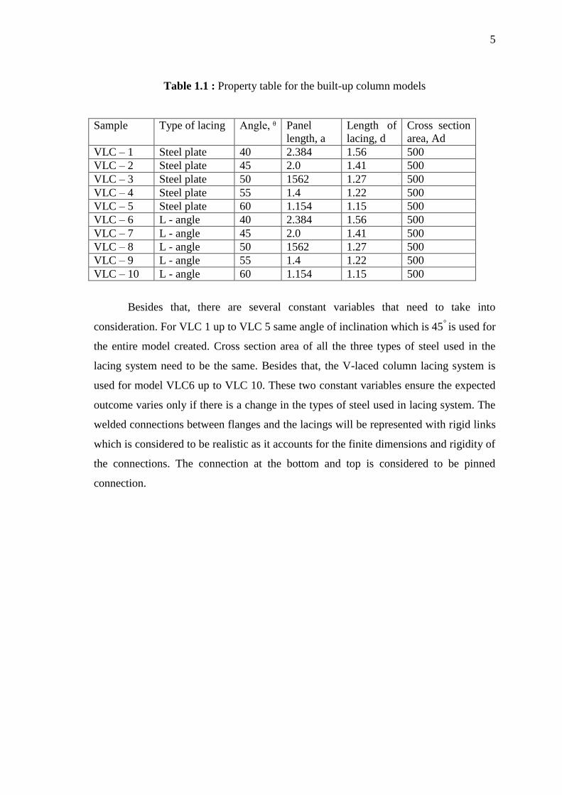
Table 1.1 : Property table for the built-up column models
Sample Type of lacing Angle, ᶿ
Panel
length, a
Length of
lacing, d
Cross section
area, Ad
VLC – 1 Steel plate 40 2.384 1.56 500
VLC – 2 Steel plate 45 2.0 1.41 500
VLC – 3 Steel plate 50 1562 1.27 500
VLC – 4 Steel plate 55 1.4 1.22 500
VLC – 5 Steel plate 60 1.154 1.15 500
VLC – 6 L - angle 40 2.384 1.56 500
VLC – 7 L - angle 45 2.0 1.41 500
VLC – 8 L - angle 50 1562 1.27 500
VLC – 9 L - angle 55 1.4 1.22 500
VLC – 10 L - angle 60 1.154 1.15 500
Besides that, there are several constant variables that need to take into
consideration. For VLC 1 up to VLC 5 same angle of inclination which is 45° is used for
the entire model created. Cross section area of all the three types of steel used in the
lacing system need to be the same. Besides that, the V-laced column lacing system is
used for model VLC6 up to VLC 10. These two constant variables ensure the expected
outcome varies only if there is a change in the types of steel used in lacing system. The
welded connections between flanges and the lacings will be represented with rigid links
which is considered to be realistic as it accounts for the finite dimensions and rigidity of
the connections. The connection at the bottom and top is considered to be pinned
connection.

6
1.5 SIGNIFICANCE OF STUDY
Built-up column is made up of steel column attached with steel lacings. There
are many researches and studies regarding the capacity of the column. Most of the
studies focused on the chord of the column. There had been less studies conducted on
the lacings part of the column. Thus, based on my study on the lacings orientation and
section on the performance of the column will be helpful in order to further specify the
factors contributing to the capacity of the column.
Furthermore, the study is conducted using the finite element software Ansys
12.0. The common laboratory research methodology conducted, will consume time and
cost. Nowadays, the most powerful method for structural analysis is the finite element
method (FEM). The simplifications and idealizations of real structural conditions have
influence on the final results. The usage of Ansys 12.0 software is efficient to provide
informative data to analyze the structural components of built-up column.
CHAPTER 2
LITERATURE REVIEW
2.1 INTRODUCTION
Built-up columns are used in steel construction when the column buckling
lengths are large and the compression forces are relatively low. In general, built-up
columns are used in industrial buildings, either as posts for cladding when their
buckling length is very long, or as columns supporting a crane girder ( " Detailed
Design of Built-up Column ", 2008 ).
A built-up column is a kind of compression member consisting of two or more
longitudinal elements ( chords ), which are slightly separated and connected to each
other at only a few locations along their lengths by means of connector-like lacings,
battens or perforated plates. These members are frequently used as light compression
members, such as truss members, bracing members and columns of light steel
structures. It is believed that the connectors causes built-up members to behave as one
integral unit to achieve maximum capacity ( " Analytical Investigation of Cyclic
Behaviour of Laced Built-up Columns ",2012 )
Differentiating built-up column from other structural members is the interaction
between global and local buckling modes. The former is associated with buckling of the
built-up member as a whole, while the latter with local buckling of chord components
between the points at which the chord and the shear system are connected. The effect of
the interaction between global and local buckling in built-up members was investigated
by Koiter and Kuiken (1971). It was concluded numerically that a laced built-up column
8
can fail either due to elastic failure of the whole column or due to local inelastic failure
of a part between joints of connectors under compression, and that in the first case EC3
may give unsafe results.
According to Charis J.Gantes et.al (2014), built-up column are often used in
steel building and bridges providing economical solutions in cases of large spans and /or
heavy loads. Depending on the way that the flanges are connected to each other, they
can be grouped into laced and battened built-up columns. Laced columns are
investigated in the present work, in which the flanges are connected with diagonal bars,
thus establishing truss like action.
2.2 MATERIAL
According to Konstantinos et.al (2014), the types of chords used plays a major
role in the capacity of the column. In the experiment test, two types of chords, IPE80
and UNP60 were used. IPE80 had a bigger cross section area compared to UNP60.
From the experiment the collapse load obtained for IPE80 was 309kN whereas for
UNP60 the collapse loads was197.8kN. Thus, this proved that cross sectional area
influence the most in the capacity of the column. From his study on the built-up column
the chord member properties were determined for the study of finite element modelling.
The selection of either channels or I-sections for chord members provides
different advantages. I-sections are more structurally efficient and therefore are
potentially shallower than channels. For built-up columns with a large compressive
axial force, I or H sections will be more appropriate channels. Chords may be adequate
in order to provide two flat sides.
Compression members composed of two angles, channels, or tees back-to-back
in contact or separated by a small distance shall be connected together by tack riveting,
tack bolting or tack welding so that the individual sections do not buckle between the
tacks before the whole member buckles. These are special types of columns called laced
and battens columns. When compression members are required for large structures like
bridges, it will be necessary to use built-up sections. They are particularly useful when

9
loads are heavy and members are long. Built-up sections are popular in India when
heavy loads are encountered. the cross section consists of two channel sections
connected on their open sides with some type of lacing or latticing to hold the parts
together as one unit. The ends of these members are connected with battens plates
which tie the ends together. ( "Design of Steel Structures", 2008 )
2.3 LACING TYPES
Lacing is one of the part of built-up column. It provides connections between
the two chords and helps the built-up column to behave as an one integral unit. Many
aspects of the build-up column had been experimented and concluded by Konstantinos
et.al (2014). According to Konstantinos et.al (2014) the panels’ length influences the
capacity of the column. This shows that the lacing system is one of the factors
influencing the capacity of the column. It was concluded that the heavily built panels
influence the capacity of the column. No local buckling was also observed with the
specimen tested for the shorter panel length.
There are many types of lacings for the built-up column. V-shape, N-shape and
X- shape lacings are the common lacings types that are used in the built-up column. The
V-shape arrangement of lacings increases the length of the compression chords and
diagonals and provides a reduction of buckling resistance. This arrangement is used in
frames with a low compressive force (" Detailed Design of Built-up Column ", 2008).
The N-shape arrangement of lacings, can be considered as the most efficient
truss configuration, for typical frames in industrial buildings. The web of the N-shape
arrangement comprises diagonals and posts that meet at the same point on the chord
axes. This arrangement reduces the length of the compression chords and diagonals. It is
usually used in frames with a significant uniform compressive force. the V-shape
arrangement of lacings increases the length of the compression chords and diagonals
and provides a reduction of buckling resistance of the members. This arrangement is
used in frame with a low compressive force. The X-shape configurations are not
generally used in buildings because of the cost and the complexity of fabrication.

10
2.4 LOAD AND CONNECTION
In the study conducted by Behrokh Hosseini et.al (2013), the behaviour of build-
up column under constant axial load and cyclic lateral load were investigated. Eight
columns made up of two IPE100 as the chords and plates as the lacings were used in the
experiment. To evaluate effects of the axial load, different loads were applied on the
specimens. Two different distances were also used to show variation on effects towards
the column. The test results showed that the axial load significantly affected the
ductility, the strength and the stiffness of the columns. Different in the distances
between main chords had little effects on strength but had significant change in the
ductility. Thus, it can be concluded that the distance between main chords need to be
fixed since it affects the strength capacity of the build-up column.
There are many types of connection and load that involves and acts on the built-
up column. Loads such as axial load, cyclic load and wind load can be applied on the
built-up column. Many studies had been conducted in terms of different load types.
Study had been conducted by A. Poursamad Bonab et.al (2012), focusing behaviour of
laced column due to cyclic load. The study evaluated the effects of column's
geometrical parameters and various level of axial loads on cyclic behaviour of laced
columns. From this study, the load type was determined which was axial load.
2.5 EXPERIMENTAL AND FINITE ELEMENT MODELLING ANALYSIS
Ansys 12.0 had been used in the study of the built-up column model. Many
experimental studies had been conducted to study and understand the behaviour of the
built-up column. Ansys finite element modelling software had been widely used to
simulate the built-up column model and analyse the model by simulation.
Based on the study by Vaidotas Sapalas et.al (2013), modelling the steel built-
up column using FEM Ansys is restricted to the assumptions of National Lithuania
Code STR and Eurocode 3. The study also states that the FEM modelling of the steel
built-up column with applied end conditions being safe enough according to STR and

11
EC3. Models of the built-up column are check and run test to meet the requirements of
EC3.
The experimental efforts related to built-up column are limited. Hashemi and
Jafari (2009),compared the elastic buckling loads of battened columns with end stay
plates obtained analytically with the experimental results. They concluded that
Engesser's method is always on the safe side. The same authors compared experimental
collapse load of simply supported battened built-up columns with the ones found
analytically with the use of Ayrton-Perry method and the ultimate capacity curve
method, observing the mean value of the two procedures can be both safe and
economical.
Bonab and Hashemi (2012) investigated numerically and experimentally the
cyclic behaviour of the laced built-up columns under a lateral concentrated load and
different level of axial loading. One of their conclusions was that high level of axial
load lead to poor ductility and that laced built-up columns are acceptable for use in
moderately earthquake-prone areas. Additionally, they investigated the elastic critical
buckling and compressive capacity of centrally loaded laced columns.
Based on the experimental investigation conducted by Behrokh Hosseini (2013),
when a built-up column is subjected to a lateral load in an earthquake, it may not behave
in an acceptable manner. In his investigation, to evaluate the seismic behaviour, eight
laced column specimens were tested. These columns were subjected to a constant axial
load while a gradually increasing lateral cyclic load was applied. The experimental
results showed that several seismic characteristics of the laced column were reduced as
the axial load increased. however, in general, the seismic behaviour of the laced built-up
columns with various geometrical properties was investigated analytically, which was a
continuation of the experimental investigation of the cyclic behaviour of laced columns.
Comparison of the results showed that there is a good correlation in load-displacements,
failure modes and elastic behaviour between the experimental and the analytical
procedure generally gives a conservative prediction for the ductility of the laced
columns (" Detailed Design of Built-up Column ", 2008).

12
According to Mahmood Hosseini et.al (2013), compound buckling is also a
factor that affects the elastic critical loads of columns. This effect was studied by Duan
et.al (2002). However, in laced columns, because of the low values of slenderness of the
main chords between the lacing plates compared of the with the overall slenderness of
the built-up column, compound buckling cannot occur. With regard to the existing
complications in calculating the exact elastic critical load of built-up columns by
analytical methods, all the proposed theoretical methods contain simple assumptions,
and therefore, it is necessary to evaluate the precision of the different methods
experimental studies. Very few tests have been conducted on built-up columns.
Hosseini Hashemi and Jafari (2009), have investigated the elastic critical load and
compressive capacity of batten columns through laboratory tests and have assessed the
precision level of the theoretical formulas. However, such tests have not been reported
for laced columns.
The finite element method had been used to study the behaviour of single , as
well as composed CFS structural members. The studied composed members, however,
are of small scale and interconnected with self-tapping screws. Reasonable
correspondence with experimental results has been reported, depending on the initial
assumptions and complexity of the model.
General guidance for non-linear FEA of thin walled members are given by
Bakker and Pekoz (2003). The authors emphasize on the importance of engineering
judgement for determining the model input and for results interpretation. The effect of
initial imperfections and residual stresses on the accuracy of computational model is
addressed by the same author. The authors summarise a set of guidelines for the
implementation of imperfections residual stress in a numerical model. These include
simple rules of thumb for the amplitude of localised imperfections, as well as
imperfection spectrum, based on existing experimental data. The spectrums allow for a
quick assessment of the imperfection amplitude for a particular buckling wavelength.
Dubina and Ungureanu (2002) studied the erosion of the theoretical buckling
strength of CFS channels in bending and compression, due to initial imperfections in
single and coupled instability failure modes. The analysis is based on non-linear FE

13
simulations, from which the higher sensitivity of the distortional-overall interactive
buckling to sectional imperfections is demonstrated. Non-linear finite shell element
models have been used by Shifferaw and Scafer (2007) to calibrate the Direct Strength
Method design expressions for beams, to account for the existing inelastic bending
reserve in local and distortional buckling. The findings of the numerical investigations
are validated based on C- and Z-section beams. The authors note an important
distinction between members free to warp and members, in which warping is restricted.
Seo et.al (2011) described complex light steel beams, resembling channels with
rectangular hollow flanges and slender webs with circular openings. These were studied
using linear finite element solid models. Linear buckling analysis was used to derive the
elastic lateral-torsional buckling moments, needed for code-based predictions of the
overall moment capacity. The authors proposed simplified modelling techniques, based
on equivalent web thickness, to account for opening in the web. The recommendations
are to be used in approximate FE models or explicit elastic buckling numerical
solutions, derived by authors.
Narayanan and Mahendran (2009) investigated distortional buckling in 16
innovative cross section shapes of CFS columns. Because the overall capacity, obtained
based on the Australian design code, over predicted the capacity of the columns
significantly, finite elements model were used to study the failure mechanisms and
obtain the axial compression capacity. The models included geometrical imperfections
and residual stresses. They established that residual stresses had a very small effect on
the ultimate compression capacity. The numerical analyses are validated by 15
experiments on column if intermediate length, which failed in distortional buckling with
very little post-buckling strength.
Lim and Nethercot (2003) used finite element models to study the ultimate
strength and stiffness of connections of light-steel frames, as well as single lap-joints
between thin CFS plates. The models could only give a good prediction of the response,
observed during the experiments, after the slip in bolts was eliminated from the
experimentally measured graphs.