finite element modeling of unreinforced masonry … · finite element modeling of unreinforced...
TRANSCRIPT

FINITE ELEMENT MODELING OF UNREINFORCED MASONRY
Asok K. Ghoshl, Arnde M. Arnde2
, and James Colville3
1. ABSTRACT
A finite element model has been developed for the analysis of masonry walls of solid brick and mortar. The constitutive law for the brick and the mortar is considered as elastoplastic. A smeared crack approach is adopted to simulate cracking of both the brick and the mortar. Crack propagation is based on the concept of fracture energy -a constant material property. The interface between the brick and the mortar is
modeled to be subjected to bond failure and friction. An elastic-softening behaviour is adopted to model the bond failure of the interface in tension. The model has been used to reproduce the experimental results of previous investigators.
2. INTRODUCTION
The finite element modeling of unreinforced masonry requires the consideration of different strength and deforrnation characteristics of its constituents, the brick and tbe mortar, and specially, the slip and separation behavior at the interface between tbem. In the early attempts of finite element modeling, the masonry assembly has been treated as a one-phase material. The material properties needed for such modeling were obtained by experiments on small masonry assemblages [1-5]. These one-pbase material models, mostly based on experiments on small specimens, are not adequate for capturing extensive stress redistribution at high stress levei and local
Keywords: Brick; Mortar; Walls; Elastoplastic; Cracking.
I Ph.D. Candidate, Department of Civil Engineering, University of Maryland, College Park, Maryland 20742, USA
2 (Formerly Arnde M. Wolde-Tinsae) Professor and Director of Graduate Studies, Dept. of Civil Engrg., University of Maryland, College Park, Maryland 20742, USA
3 Professor and Chairman, Department of Civil Engineering, University of Maryland, College Park, Maryland 20742, USA
61

behavior in large building components with door and window openings. To be able to reproduce the local behavior of masonry, it is essential to model masonry as a twophase material. In the development of analytical models based on two-phase material two approaches have been adopted.
In one approach, to avoid elaborate and expensive numerical computations, the masonry assemblage has been modeled as bricks connected by interface elements which collectively represent the strength and deformation characteristics of the mortar and bond and friction behaviour of the joints between the mortar and the brick. Page [6] modeled masonry for the investigation of stress distributions in masonry rather than the accurate prediction of final failure. The bricks were assumed elastic and isotropic and the interface behavior included joint mechanisms including failure. The stress-strain diagrams for both brick and mortar were obtained by experiments. In tension, the joint failure is elastic-brittle. In compressive stress regions, the joint stiffness in the thickness direction remains unchanged and a shear retention, proportional to the normal stress, procedure is adopted. This model was able to reproduce the stress distributions in a deep masonry beam under vertical load, even for higher loads when substantial stress redistributions occurred. No loaddisplacements comparison between the model and the experiment is available. Also, the ultimate failure load could not be obtained due to the absence of a failure criterion for bricks. Rots and Lourenco [7] modeled masonry in a similar manner in which interface behavior is based on the results of extensive micro-experiments. The main emphasis of this model is the tension and shear softening of the interface. The elastic domain of the interface is a Coulomb shear model under compressive normal traction and a parabolic tension cutoff under tensile normal traction. After yielding, flow follows a non-associated plasticity role. For the stress state within the failure envelope, a linear elastic model is assumed and the stiffness matrix for the interface element is obtained from the Young's modulus and the Poisson's ratio of the mortar. Under the compressive normal stress and the stress state outside the envelope, a non-symmetric instantaneous tangent stiffness matrix results. On the tension side, crack initiation is assumed if the stress state falls outside the envelope. As the crack initiates, a softening formulation in the direction of the resultant of the traction is used. The material models were derived by micro-experiments by Pluijm and Vermeltfoort [8-10]. The experimental result exhibits an almost constant friction angle (no friction hardening or softening) and a softening of the cohesion as a function of the plastic shear slip. The dilatancy angle in shear decreases with increase in pressure and slip. However, a constant value of dilatancy angle was used. The failure in tension in the brick due to Poisson's effect [11] was simulated with an effective strength of brick in compression. The above mode! was used to simulate full scale tests on shear walls of the same size and subjected to the same precompression and lateral!oads. To match the experimental results with the analytica! results, the addition of the Von Mises failure criteria for the bricks and the cohesion softening behavior in the Coulomb mode! as a function of the plastic relative displacement was necessary. The mode! predicted high ultimate !oad which prompted the inclusion of a cracking model for bricks in tension. A smeared cracking model was added but no result was reported because of some numerical problems.
In the other approach of two-phase material mode!, both the brick and the mortar
62

are modeled as continuum and the bond and friction behavior at the brick-mortar interface is monitored for possible slip and separation. Ali and Page [12] modeled masonry for the analysis of brick masonry walls subjected to concentrated vertical loads. Both the brick and the mortar were modeled by 2-D continuum elements. Material models for both the brick and the mortar are considered to be elasto-plastic with Von Mises failure criterion with a tension cu to ff. Bond failure between brick and mortar was found to be a function of normal and shear stresses acting at the joint. The emphasis of this model is on the tensile fracture of brick due to stress concentration due to vertical mortar joint failure below the brick. The crack initiation is based on strength criterion and the effect of cracking is based on smeared crack mode!. This model was used to reproduce the results of experiments on walls subjected to vertical load. A reasonable agreement was obtained between the theoretical model and the experiment. However, predicted ultimate loads were consistently lower than the experimental value. This prompted the consideration of strain softening for the post-cracking behavior. To match the experimental ultimate load several slopes of the post cracking stress-strain diagram were investigated and the one which provided the correct ultimate load was based on the final strain equal to the six times the cracking strain. A similar analytical model but with triaxial constitutive law and failure surface was presented by Ignatakis, Stavrakakis and Penelis [13]. This model is capable of simulating damage in units, mortar joints and predicting both joint and composite type of failure, due to in-plane stresses in conjunction with the transverse stress which develops due to unequal dilatancy of mortar and brick. The model uses Hooke's law for three dimensional elasticity with Young's modulus being instantaneous for each increment. The Poisson's ratio is also varied during the increment of loading. The instantaneous Young's modulus is based on the equivalent uniaxial stress strain diagram which is a function of the instantaneous triaxial stress vector inside the failure envelope and, along the same direction, the ultimate stress vector. The joint failure criterion has a tension cutoff before bond failure due to te"nsion and shear. After failure this criterion follows the Mohr-Coulomb failure envelop with zero cohesion. This model was used to reproduce the results of tests on solid brick masonry wallets by Dhanasekar, Page and Kleeman [3]. The authors reported an estimated 25% of strain underestimation in alI the stress-strain curves that were obtained by their mode!. This discrepancy was attributed to the fact that not all the material properties were available in [3]. Colville and Samarasinghe [14] based on the importance of Poisson's effect, modeled the bed joint as continuum but the head joint as a linkage element as described previously [6]. The stiffness matrix of the horizontal joint is based on uniform vertical and horizontal deformation of a mortar elemento The properties of the brick and the mortar and joint used in the model were taken from [6]. The deformation characteristic of brick was assumed elastic-brittle and a failure criterion similar to that of concrete was adopted. This model was verified by comparing the results of the analysis of a wall beam with the experimental results reported in [6]. The model predicted the stress distributions on a horizontal section of the wall and the ultimate concentrated load reasonably accurately.
In the present work, the computer code "ABAQUS" [15] is used to model masonry walls subjected to vertical and/or horizontal loads. The masonry is modeled as a two-pbase material in which the brick and the mortar are modeled as continuum. The bond and friction behavior at the interface between the brick and the mortar is
63

modeled in a way similar to the one described previously. The details of the analytical model are described below.
3. CONSTITUTIVE MODELS FOR BRICK AND MORTAR
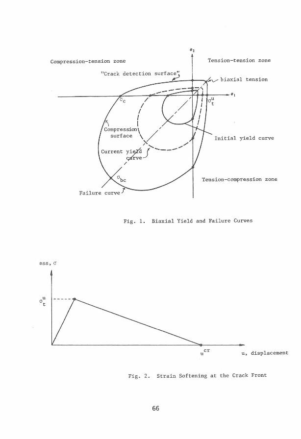
The elastic-plastic behavior in a predominantly compressive stress state and elasticstrain softening behavior in tension of both the brick and the mortar are modeled using the inelastic constitutive model for concrete available in 'ABAQUS' [16, 17]. The elastic-plastic model for brick and mortar uses the classical plasticity theory which comprises of a strain rate decomposition into elastic and inelastic strain rates, elasticity; yield; flow; and hardening. The yield surface is written in terms of the first two stress invariants. In two dimensions, the yield and failure curves are as shown in Fig. 1. The compression yield function and the potential function for flow are the same and isotropic hardening is used. The associated flow rule assumed can not predict the correct inelastic volumetric strain. The elas ti c stiffness is assumed to remain constant even beyond the ultimate stress point. This assumption does not reproduce the significantly weakened unloading response because of the damage of the elastic response of the material. The failure surface formed by a Mohr-Coulomb formulation and in general stress state is given by
( 1)
wherep = -1/31 in which 1 is the first invariant of the stress tensor; q = pJ2 in
which Jz is the second invariant of the deviatoric stress tensor; ao is a constant, which is chosen from the ratio of the ultimate stress reached in biaxial compression to the ultimate stress reached in uniaxial compression; 1 eis the size of the yield surface on the q-axis at p = O. The value of ao is found by comparing the above failure surface in uniaxial compression and in biaxial compression. The quantity ao is a function of the ratio of the biaxial failure stress (ai = a2), abc and the uniaxial failure stress, acThis ratio is required as input. For concrete, the typical value for the above ratio is 1.16. Biaxial test results on brick and mortar are not available from the literature. Consequently, the above value has been chosen as the ratio of biaxial failure stress to the uniaxial failure stress for the brick and the mortar. Once ao is known, the value of 1 c can be determined from the uniaxial test data.
The plastic strain vector is obtained from the associated flow rule
dePL = dI. (1 + c (..E..)2) af c c c o 0c ao (2)
where Àc is the flow parameter and Co is a constant. The value of Co is found by comparing the failure plastic strain for biaxial test and that for uniaxial testo The term Co is a function of the ratio of the failure plastic strain in a monotonically loaded biaxial compression test to that in a monotonically loaded uni axial compression test. The biaxial test data for both the brick and the mortar is not available. Consequently a typical value for the above ratio for concrete, 1.28, is chosen. Once Co is known, the value of the flow parameter, À", can be found from the uniaxial test data.
64

In a predominantly tensile stress state, the present model uses a smeared crack model. It uses a "crack detection" plasticity surface in stress space to determine when cracking takes place, and the orientation of cracking. Once the crack's presence and orientation have been detected, the model subsequently uses the cracked material properties.
The post cracking behavior foIlows the concept of strain softening zone or fracture process zone at the crack front (Fig. 2) for crack propagation [18, 19]. The fracture energy, required to form a unit are a of crack surface, Gr. is assumed to be a constant material property. The fracture energy is a function of the cracking tensile stress in a multiaxial stress state and the crack opening displacement, ucr
, at the crack front where stress becomes zero. This displacement is supplied as input to the programo From uO", the strain hardening parameter, required for determining the crack detection surface, is defined. The fracture energies for the brick and the mortar are obtained fram [8]. The crack opening displacements for the brick and the mortar are obtained fram above mentioned fracture energies and the tensile strengths of the brick and the mortar given in [12]. The crack detection surface is defined as
f = q - (3 - b .:!..E.) p - (2 - b o .:!..E.) o = O t o u 3 u t
a t a t
(3)
where p and ~ are defined in the same way as p and q, except that aIl stresses associated with open cracks are not included; a~ is the failure stress in uniaxial tension, bo is a constant and is obtained by defining two ratios one of which, f, is the fraction of the uniaxial failure tensile stress which wiIl cause cracking in a biaxial stress state in the presence of the compressive failure stress in the perpendicular direction. The other ratio is y7 = aU a~. Based on these conditions, the stress measures p and q can be found and are inserted in the yield function to determine bo• The ratio y7 for the brick and the mortar are obtained fram [12]. They are respectively .077 and .104. It is assumed that f is .33 for both the brick and the mortar. The equivalent uniaxial tensile stress, a" is related to the flow parameter Á,
by the following flow rule
d€~L = dÁ afe t ao
Using the definition of f, [Eq. (3)], the flow rule can now be written as
(4)
(5)
In uniaxial tension, Sl1 = 2/3 a" and q = a, and the plastic strain is defined as uO" /c, where c is the characteristic length associated with the integration point. The chracteristic length is based on element geometry. As the direction of cracking is unknown, if there are elements in the model with large aspect ratios, the model will likely pravide different results if it is loaded in different directions and cracking occurs in such elements. À, can now be obtained from Eq. (5) by inserting the above values for s, q and d€~L and therefore alÀ,) relationship is obtained. Following cracking, the brick and the mortar are subjected to shear stiffness reduction which is a function of the opening strain acrass the crack. Also, the shear modu\us has a reduced value for closed cracks. If the normal stress across a crack becomes
65
Compression-tension zone Tension-tension zone
ess, o
"Crack detection S_U_r_f_a.-J.C",-~e_" __ t-_oy.:: tension
_______________ ~~------~~--~~----~~~~---~al /
Failure
/ / I I
COl!lpression\ / surface \
X ./ " ..... yi~ j ----91'rve
Initial yield curve
Tension-compression zone
Fig. 1. Biaxial Yield and Failure Curves
cr u u, displacement
Fig. 2. Strain Softening at the Crack Front
66

compressive, the new shear stiffness gets degraded.
4. BEHAVIOR OF INTERFACE BETWEEN BRICK AND MORTAR
The interface surfaces rema in bonded until the biaxial state of stress at the interfaces reaches the failure function
(6)
where a n is the normal stress and r is the shear stress carried across the interface; af and r f are the normal and shear failure stresses. The interfaces start debonding when the state of stress reaches the above failure function. The softening behaviour of debonding has been simulated using the experimental results of [8, 9]. After debonding, the interface surfaces interact following the classical Coulomb friction model. The surfaces do not slide over each other so long as the shear stress magnitude is less than J.1" the coefficient of friction, times the pressure stress between them.
The present model has been used to reproduce the experimental results of [12] and [20]. The results of the mo deI are not available at present.
5. REFERENCES
[1] Hegernier, G.A, Nunn, R.O., Arya, S.K., "Behaviour of Concrete masonry Under Biaxial Stresses," Proceedings of the North American Masonry Conference, U.S.A., 1978, pp. 1.1-1.28.
[2] Page, A W., 'The Biaxial Compressive Strength of Brick Masonry," Proceedings of the Institution of Civil Engineers, part 2, 1981, 71, Sept., pp. 893-906.
[3] Dhanasekar, M., Kleeman, P.W., Page, AW., "Biaxial Stress-strain Relations For Brick Masonry," Journal of Structural Engineering, American Society of Civil Engineers, Vol. I1I, No. 5, May, 1985, pp. r085-1100.
[4] Dhanasekar, M., Page, AW., Kleeman, P.W., "The Failure of Brick Masonry Under Biaxial Stresses," Proceedings of the Institution of Civil Engineers, Part 2, 1985, 79, June, pp. 295-313.
[5] Riddington, J.R., Ghazali, M.Z., "Hypothesis For Shear Failure In Masonry Joints," Proceedings of the Institution of Civil Engineers, Part 2, 1990, 89, Mar., pp. 89-102.
[6] Page, AW., "Finite Element Model For Masonry," Journal of Structural Division, Arnerican Society of Civil Engineers, Vol. 104, No. 8, 1978, pp. 1267-1285.
67

[ 7] Rots, J.G., Lourenco, P.B., "Fracture Simulations of Masonry Using Nonlinear Interface Elements," Proceedings of the Sixth North American Masonry Conference, 1993, VoI. 2, pp. 983-993.
[ 8] Pluijm, R.v.d., "Material Properties of Masonry and Its Components under Tension and Shear," Proceedings of the Sixth Canadian Masonry Symposium, Saskatoon, Canada, 1992.
[ 9] Pluijim, R.v.d., "Shear Behaviour of Bed Joints," Proceedings of the Sixth North American Masonry Conference, Pennsylvania, U.S.A., 1993.
[10] Vermeltfoort, AT., "Mechanical Properties under Compression of Masonry and Its Components," Proceedings of the Sixth Canadian Masonry Symposium, Saskatoon, Canada, 1992.
[11] McNary, W.S., Abrams, D.P., "Mechanics of Masonry in Compression," Journal of Structural Engineering, American Society of Civil Engineering, VoI. 111, No. 4, April, 1985.
[12] Ali, S., Page, AW., "Finite Element Model For Masonry Subjected to Concentrated Loads," J ournal of Structural Division, American Society of Civil Engineers, VoI. 114, No. 8, August 1988, pp. 1761-1783.
(13] Ignatakis, c., Stavrakakis, E., Penelis, G., "Analytical Model for Masonry Using the Finite Element Method," Structural Repair and Maintenance of Historical Buildings, Computational Mechanics Publications, 1989.
[14] Colville, J., Samarasinghe, W., "Finite Element Model for Brick Masonry," Proceedings of the Ninth International Brick/Block Masonry Conference, 1991, VoI. 2, pp. 726-734.
(15] Hibbitt, Karlson & Sorensen, Inc., "ABAQUS," Version 5.2, 1992.
(16] Hegernier, G.A, "Evaluation of Models for MX Siting-Volume 11 - Reinforced Concrete Models," Systems, Science and Software, Report SSS-R-80-4155, Systems, Science and Software, Lajola, California, 1979.
(17] Hegernier, G.A, Cheverton, KJ., "Evaluation ofReinforced Concrete Models for Nuclear Power Plant Application," EPRI, Paio Alto, California, 1980.
(18] Hillerborg, A, Modeer, M., Petersson, P.E., "Analysis of Crack Formation and Crack Growth in Concrete by Means of Fracture Mechanics and Finite Elements," Cement and Concrete Research, Vol. 6, 1976, pp. 773-782.
[19] Bazant, Z.P., "Mechanics of Fracture and Progressive Cracking in Concrete Structures, Fracture Mechanics of Concrete: Structural Application and Numerical Calculation (eds., G.c. Sih and A DiTommaso), 1984, pp. 1-85.
68

[20] Fattal, S.G., Cattaneo, L.E., "Structural Performance of Masonry Walls under Compression and Flexure," NBS building Science Series 73, U.S. Department of Cornrnerce/National Bureau of Standards, June, 1976.
[21] Chen, W.F., "Plasticity In Reinforced Concrete," McGraw-Hill Book Company, 1982.
[22] Kupfer, H.B., Gerstle, KH., "Behaviour of Concrete under Biaxial Stresses," Journal of Structural Division, American Society of Civil Engineers, Vol. 99, 1973, pp. 853-865.
[23] Gilbert, RI., and Warner, RF., "Tension Stiffening in Reinforced Concrete Slabs," Journal of Structural Division, American Society of Civil Engineering, Vol. 104, ST12, 1978, pp. 1885-1900.
[24] Lotfi, H.R, Benson Shing, P., "Interface Model Applied to Fracture of Masonry Structures," Journal of Structural Engineering, American Society of Civil Engineers, Vol. 120, No. 1, January, 1994, pp. 63-80.
[25] Sharma, K.G., Desai, C.S., "Analysis and Implementation of Thin-Layer Element for Interfaces and Joints," Journal of Engineering Mechanics, American Society of Civil Engineers, Vol. 118, No. 12, December, 1992, pp. 2442-2462.
69

70