finite element modeling of girth welded pipe with multiple
TRANSCRIPT
Indian Journal of Engineering & Materials Sciences Vol. 27, June 2020, pp. 687-698
Finite element modeling of girth welded pipe with multiple defects
Hsu Yang Shang* & Ivan Ferreira da Silva
Graduate Programin Mechanical Engineering– Pontifical Catholic University of Paraná
1155 Imaculada Conceição Av., Zip code 80215-901, Curitiba – PR – Brasil
Received:22 October 2018 ; Accepted:24 October 2019
Due to the expansion of the pipeline network in the transportation of petroleum and its derivatives, it has been essential to develop studies to evaluate and guarantee the safety condition, as well as the reliability of such facilities. Welded pipelines have been widely used, and they are susceptible to corrosion. Since the heating at the welded point may leads to structural and compositional modifications in the material, which may generate corrosion. The present paper presents a nonlinear computational model burst pressure assessment in API X70 girth welded pipes with multiple defects, created by corrosion, which may represent a great risk for gases and fuel leakage during transportation. In this study, the computational model has been developed by the finite element method considering the isotropic hardening model and contact conditions between different materials involved in the analysis, with corrosion simulated as a rectangular defect. The corroded pipe and the efficiency of the computational model have been analyzed by varying the width of the heat-affected zone (HAZ), and the depth of single and multiple defects. The results obtained by using the finite element analysis have been compared with the semi-empirical methods and literature results. The computational model developed by the present work has presented satisfactory results.
Keywords: Corrosion, Girth welded pipes, Finite element analysis, Burst pressure
1 Introduction In the past decades, there is an increase in the
production of oil and natural gas in Brazil, evidenced by the data presented by ANP1. Domestic oil production grew 3.2%, in its third consecutive year of increase and reached 2.5 million barrels per day. In the same sense, the national production of natural gas has increased by 7.9% to 103.8 million cubic meters per day. In this scenario, it is evident that the pipelines will be widely installed for the transportation of these energy sources. The pipelines are the safest and lowest cost means in transportation and is one of the resources that less damages the environment, besides it has high efficiency and productivity. Even with the benefits that the pipelines provide, the Brazilian pipeline extension is still small compared to other countries, such as the United States, Mexico, Argentina, and Australia.
In order to transport fluids in a safe way by pipelines, it is necessary to identify the existence of defects and evaluate the possible impact that this irregularity can cause in the pipeline mechanical integrity. These defects often appear in the welded region and they are generally generated by
corrosion. Therefore, when the loss of mechanical strength due to corrosion is found, a decision should be made in the pipeline operational condition, if it is necessary to reduce the operating pressure, or interrupt the transportation to carry out necessary repairs. The present work deals with the burst pressure assessment in welded and corroded pipes. Considering that the corrosion in buried pipes often occurs near the weld region.
There are numerous studies developed during the recent decade in the corroded pipe analysis, and a brief literature review is presented in the following, concerning several aspects of research interests. The three-dimensional finite element approach of corroded pipe with defect is widely employed and different geometries are investigated, with the purpose to better model the corrosion2-4. These geometries include rectangular, semi-elliptic, spherical profile, among the others. Other efforts are addressed to develop a new profile to model complex corrosion profiles, such as pits5. These researches are conducted in the pipe subjected to combined loading and aim to investigate the stress concentration effect in the vicinity of the defect and plastic instability that occurs in the pipe6-7. Besides the finite element approach, experimental burst test and semi-empirical methods are also studied
—————— *Corresponding author (E-mail: [email protected])

INDIAN J ENG MATER SCI, JUNE 2020
688
and developed to assess the burst pressure using different mechanical strength of pipe8-12. The influence of length, width, and depth of the defect on the burst pressure are investigated, with the purpose to identify which one has more significant influence13-14. Moreover, not only the single defect is studied during these years, but also the multiple defects. Several researches are addressed in the study of interaction between defects of same profile or different profiles15-
17. Besides the three-dimensional finite element approach, many researches are also carried out in the development of a simplified methodology, that aims to reduce computer time processing and computational effort. This methodology is based on beam-pipe element that uses stress concentration factor to simulate the existence of corrosion18. Finally, several researches are developed with the focus in the girth and seam welded pipe, with corrosion that appears in the weld region. Numerical and experimental approaches are developed to assess the burst pressure19-20. From the briefly presented literature review, it is possible to observe that there are still few works addressing the issue handled in this paper, which is the numerical modeling of corroded and welded pipe, by using three-dimensional finite element approach, considering contact conditions between different parts of material.
The present work aims to develop a computational model by using the finite element method to assess the burst pressure considering the elastoplastic behavior of welded pipe with corrosion. The burst pressure is determined in pipes by varying the width of the heat-affected zone (HAZ), with 35%, 75% and 100% of the pipe wall thickness. The purpose is to verify if the variation of HAZ width affects the value of burst pressure. Furthermore, the burst pressure is also determined by varying the defect depth in pipe containing single defect. For the effect of numerical model validation, the results were compared with literature ones, in order to validate the performance of the proposed model. Subsequently, the burst pressure is determined in the pipe with multiple defects, present in the weld bead and positioned in circumferential direction. These analyzes occur with the variation of the depth of the defects. The results of this work are compared to the literature results and those obtained by semi-empirical methods, such as ASME B31G, ASME modified B31G, DNV RP-F101(recommended practice by Det Norske Veritas), and PCORRC(pipe corrosion criterion) method. This
work contributes to the development of finite element approach in the corroded and girth welded pipe and propose a modeling methodology which provides satisfactory results and presents competitiveness in comparison to literature and semi-empirical method.
2 Semi-Empirical Methods
This section presents briefly some semi-empirical methods widely used in the determination of burst pressure. The ASME B31G method21 is one of the pioneer methods in burst pressure evaluation and it is widely used due to its conservatism. However, this conservatism is known as excessive in the corroded pipe with long defects. Therefore, the B31G method was modified and other methods were proposed, such as modified method 085dL. Moreover, the DNV RP-F10122 method was proposed to determine burst pressure in pipe of high strength, considering the plastic collapse mechanism where the ultimate stress is considered in its formulation. The PCORRC method is employed for pipe of high to moderate strength and this method considers that the plastic collapse failure pressure is controlled by the ultimate stress. These methods are employed in present work for effects of comparison with numerical results obtained by finite element model. In the following equations, a denotes the corrosion depth, is the external diameter and t is the pipeline wall thickness. 2.1 B31G Method
In the formulation of this method, it is considered the corrosion and pipe geometry, and mechanical properties. The corrosion defect is represented by the projection of the corrosion area in a rectangle shape in the longitudinal section of the pipe. According to the ASME B31G method, it is necessary to calculate the dimensionless factor to evaluate whether the defect can be considered as short or long. The defect is considered short if the referring factor is less than or equal to 4.If the factor is greater than 4, then the defect is considered long.
= 0.893 a . ..(1)≤ 4, for short defects, the B31G method
suggests:
á = 1.1 2 1− 23 a1− 23 √ + 1
...(2)

SHANG & SILVA: FINITE ELEMENT MODELING OF GIRTH WELDED PIPE
689> 4, for long defects, the B31G method suggests:
á = 1.1 2 1− a
...(3) 2.2 085dL Method or B31G Modified
This method uses an empirical factor of 0.85 to represent the corrosion projection area in the longitudinal section of the pipe with a combination of parabolic and rectangular format.
á = + 69 2 1 − 0.85 a1− 0.85 a ...(4)
In this method, it is also possible to separate the
analyzes in short or long criteria according to the calculation of the dimensionless factor . The defect is considered as short if the result referring to the factor is less than or equal to 6.3.If the factor is greater than 6.3, then the defect is considered as long. = 0.893 a
...(5)
≤ 6.3, for short defects, the B31G modified method recommends: = 1 + 0.6275 − 0.003375
...(6)
> 6.3, for long defects, the B31G modified method recommends: = 3.3 + 0.032 ...(7)
2.3 DNV RP-F101Method This method uses an empirical factor to represent a
rectangular corrosion format, which is considered as a severe situation. The burst pressure is determined by Eq. (8).
á = 2− 1− a1− a
...(8)
where, = 1 + 0.31
...(9) 2.4 PCORRC Method
This method presents the following formulation:
á = 2 1− a
...(10)where,
= 1 − −0.157 − a2
...(11) 3 Computational Model Description
This section describes the computational model developed in this work. The pipe material adopted in this work is API 5L X70, as the base metal and the heat-affected zone. The weld is constituted byER70S-G consumable. The stress-strain curves of the base metal, HAZ and filler metal are obtained by Kim20 and adapted in this work, according to Fig. 1.The data collected by Fig. 1 are used for the von Mises isotropic hardening model, where they are used to simulate the behavior of three materials. Thus, by interpolating the points of the curve obtained in the experiment, it is possible to extract the numerical values of stress and strain, as shown in Table 1
The finite element model23-26 is developed by using commercial software, ANSYS, and the physical nonlinearity is considered for small displacement and infinitesimal strain, characterized by mechanical behavior of corroded pipe. The geometry of the defect has a rectangular shape, because it presents stresses concentration in the corners. The geometric properties considered for the simulation are listed as follows:
Pipe length: 750 mm; Pipe diameter: 762 mm; Pipe thickness: 15.9 mm; Defect Depth: a mm; Defect length: 300 mm;

INDIAN J ENG MATER SCI, JUNE 2020
690
Defect width: 50 mm; Young’s modulus: 207 GPa (this value was
adopted for base metal, HAZ and Consumable); Tensile yield strength: , MPa, (according
to the value of Table 1); Tensile ultimate strength: MPa, (according
to the value of Table 1); Poisson’s ratio: 0.3.
A schematic representation of a corroded pipe, weld region, and HAZ is shown in Fig. 2, and the contact conditions are defined between these materials. The contact problems range from frictionless contact in small displacements, to contact with friction on a wide variety of inelastic problems. Although the formulation of the contact conditions is similar in all cases, however, the solution in nonlinear
Table 1 — Stress-strain values obtained from the experimental test for BM, HAZ and filler metal.
API-X70 HAZ Filler metal - ER70S G
Stress [MPa]
Strain [mm/mm]
Stress [MPa]
Strain [mm/mm]
Stress [MPa]
Strain [mm/mm]
549.230 0.0037 569.218 0.0386 522.369 0.0025 553.210 0.0051 575.815 0.0403 549.518 0.0215 581.860 0.0065 585.690 0.0449 579.017 0.0316 616.520 0.0191 595.190 0.0507 607.301 0.0435 619.960 0.0202 609.184 0.0606 649.446 0.0693 623.230 0.0219 624.118 0.0732 686.466 0.1057 636.700 0.0296 632.844 0.0823 689.992 0.1108 639.880 0.0319 640.522 0.0929 692.911 0.1165 643.680 0.0349 642.479 0.0961 694.531 0.1194 647.790 0.0372 643.401 0.1007 696.577 0.1219 650.710 0.0389 643.753 0.1025 698.351 0.1247 653.390 0.0412 644.388 0.1048 699.226 0.1282 660.330 0.0487 645.664 0.1078 700.485 0.1369 666.850 0.0568 646.908 0.1107 700.711 0.1458 670.099 0.0645 647.683 0.1132 702.061 0.1468 673.070 0.0724 648.094 0.1157 703.004 0.1485 687.960 0.1465 657.336 0.1683 719.807 0.2207 702.850 0.2207 666.578 0.2207 902.679 1.0212 874.107 1.0788 827.679 1.1435 --- ---
Fig. 1 — Stress-strain curves for the BM x HAZ x Filler metal,adapted from Kim20.
Fig. 2 — Schematic representation of the model.

SHANG & SILVA: FINITE ELEMENT MODELING OF GIRTH WELDED PIPE
691
problems is much more complicated in comparison to other cases of linear problems. The nonlinearity considered in present work is not only restricted to the material isotropic hardening, but also the contact conditions.
When welding materials and base metal are connected to each other, that is, surfaces are rigidly fixed or glued, then the surfaces cannot be separated or slide one on the other. This means that the surfaces of the materials will be coupled without considering the mutual penetration of materials or the separation. Therefore, the contact condition considered in the present work is bonded. The finite element mesh is generated in each part independently, in such a manner that there could have mesh incompatibility between these parts. By consequence, creates discontinuity in the mathematical domain. To overcome this problem, the contact condition is adopted between these parts as bonded. Besides, there are also different methodologies the does not employ contact condition in the welded corroded pipe27-29. The finite element mesh is constituted by tetrahedral element of ten nodes with three degrees of freedom each, Fig. 3.As the corroded pipe contains a defect, therefore, this element is chosen to better discretize the irregular geometry domain. A ¼ model of the pipe is adopted by using symmetry conditions to reduce the computational effort and processing time. The boundary conditions are shown in Fig. 4.
•CC1: By considering the planes of symmetry, the area for the filler metal is restricted in the z-direction;
•CC2: By considering an infinite length pipe, the area of base metal is constrained in direction z;
•CC3 and CC4: According to the planes of symmetry, the areas related to the base metal, the heat-affected zone and the filler metal are restricted in direction x;
•CC5: The lines referring to the base metal, heat affected zone and filler metal are restricted in the y-direction, so that the pipe will be supported;
•CC6: The inner surfaces of the pipe, including the base metal, heat affected zone and filler metal are subjected to internal pressure.
The Newton - Raphson iterative method is employed in this work to solve the physical nonlinearity behavior of pipe, material hardening and applied contact conditions, and in this work, the energy norm is adopted as a control parameter for convergence. Due to paper length limitation, this method is not presented in detail here. Further information concerning this method can be found in the literature23,26. In this iterative method, the present work applies the pressure in the inner surface of the pipe and adopts incremental procedure. The value of pressure increment is equal to 0,1 MPa. In each iteration, the error is determined, and it is compared to the tolerance previously established, then the convergence criterion is verified considering energy norm. If the error is less than the tolerance value, which is 1x10⁻⁷, then the incremental process will proceed. When the finite element model cannot fulfill the convergence condition
Fig. 3 — Finite element mesh in the corroded region.
Fig. 4 — Boundary and loading conditions.

INDIAN J ENG MATER SCI, JUNE 2020
692
even after several iterations, then the incremental procedure is stopped. And the determined burst pressure is equal to 0,1 MPa times quantity of increments already done. 4 Applications
This section presents three analyzes carried out by the proposed computational model and aims to analyze the elastoplastic behavior of the welded pipe with corrosion. The burst pressure is calculated by computational model when it reaches the collapse state. In other words, when the energy norm determined by force and displacement is no longer converge to the limit value. The determined burst pressure is compared with literature results and those obtained by semi-empiric method. The computational model in each application has highly non-linear behavior30-31.Since it presents non-linearities of material and mainly non-linearities of the contact conditions. The first example shows the analysis that includes the variation of the HAZ width and shows its influence in the burst pressure assessment. The second example, without varying the HAZ width, investigates the influence of the variation of the defect depth in the burst pressure. Finally, the last example investigates the phenomenon of multiple defects, positioned in the circumferential direction. 4.1 Single Defect in the Girth Weld, Varying the Width of the HAZ
This analysis aims to investigate the influence of the width variation in the heat-affected zone (HAZ) that could affect the magnitude of burst pressure. The variation of HAZ width is performed according to Fig. 5(a). In this example, 0% means that there is no HAZ, that is, the pipe has only filler metal; 35% of the pipe wall thickness corresponds to a 5.5 mm HAZ width; 75% corresponds to a width of 11.9 mm and 100% corresponds to a width of 15.9 mm. The mechanical properties of the base metal, HAZ and filler metal materials are summarized in Table 1. The geometric parameters of corrosion defect are summarized in Table 2, where “ΔL” is the HAZ width, “c” is the length of the defect and "a" is the depth of the defect, and the defect width is 50 mm. In this analysis, the length and depth of the defect are maintained as the same, while the width of HAZ varies from 0% to 100% of pipe wall thickness.
In order to verify the reliability of the finite element mesh, a mesh convergence test is conducted with width of HAZ equal to pipe wall thickness. The
results are depicted in Fig. 5(b). It is possible to observe the burst pressure determined by different degree of mesh refine is decreased with mesh refine. Further, this value converges to approximately 19,8 MPa with a reasonable mesh refine. In this case, even with number of degrees of freedom equal approximately to 15x105, the result remains the same.
In this example, the burst pressure is determined with the variation of the HAZ width, as shown in Table 3. This table presents the burst pressure determined in the situation with weld and without weld. In the situation with weld, a comparison is made between the burst pressures obtained from the
Fig. 5 — (a)Defect with the variation of HAZ and (b) Burst pressure versus number of degrees of freedom, HAZ=100%*t.
Table 2 — Defect parameters with HAZ width variation.
HAZ width in [%] of wall thickness
ΔL [mm] c [mm] a [mm]
0 NA 300 7.95 (50% of t) 35 5.5 300 7.95 (50% of t) 75 11.9 300 7.95 (50% of t)
100 15.9 300 7.95 (50% of t)

SHANG & SILVA: FINITE ELEMENT MODELING OF GIRTH WELDED PIPE
693
case with HAZ width variation and the literature results20. In the situation without weld, the burst pressure was determined by well-known semi-empirical methods, such as ASME B31G, MODIFIED B31G, PCORRC, and DNV. It is well-known that these methods do not include mechanical effects introduced by HAZ or weld in its mathematical formulation. According to the semi-empirical methods, the burst pressure determined by ASME B31G and B31G MODIFIED methods is 17,24 and 16,45 MPa, respectively. On the other hand, the DNV and PCORRC methods present the burst pressure with the value 19,25 and 19,47 MPa, respectively. One may possibly observe that the burst pressure determined by PCORRC has a similar value in comparison with that is obtained by present computational model. However, it is necessary to carry out more investigation and further analysis to make a conclusion concerning this aspect.
According to the results presented in Fig. 6, it is possible to affirm that the HAZ does not have are markable influence on the burst pressure when its width varies between 0% and 100% of pipe wall thickness. Figure 7 shows a von Mises equivalent stress distribution for different width values of HAZ. It is possible to observe that the increase of the HAZ width reduces slightly the magnitude of the von Mises stress that leads to computational model collapse. According to the numerical results, the present computational model is efficient, since, regardless of the width of the HAZ, the burst pressures found in the analyzes are approximately equal to the values of the burst pressures obtained by Kim20. It is important to note that the value of von Mises stress in the collapse state is different from a case to the other. It is affected mainly by the value of increment pressure, assumed to be 0,1 MPa in present work, and the mesh refine.
Furthermore, a convergence study concerning the mesh refine is conducted before the results are obtained. 4.2 Single Defect in the Girth Weld, with the Variation of the Defect Depth
This analysis aims to evaluate the burst pressure in the pipe with variation in the depth of the defect, while the HAZ width is assumed to be the same in all cases with 5.5 mm (35% of the pipe wall thickness), since it does not have an influence on the burst pressure, as it is already observed in the previous example. The rectangular defect is located in the external surface of the pipe, being defined with 0° with respect to the y-axis, according to Fig.8.
The mechanical characteristics of the base material, HAZ and filler metal materials are defined by Table 1. In order to perform this analysis, the following geometrical parameters are presented in Table 4,
Table 3 — Comparison between the methods used and the burst pressure for HAZ variation.
Burst pressure [MPa]
Mod
el
wit
h w
eld
Present work HAZ - 0% 20,0 HAZ = 35%*t 19,9 HAZ = 75%*t 19,9
HAZ = 100%*t 19,8 Reference Results20 Computational Method 19,4
Experimental Method 21,2
Mod
el
wit
hout
wel
d Semi-empirical Methods ASME B31G 17,24 B31G
MODIFIED 16,45
PCORRC 19,47 DNV 19,25
Fig. 6 — Burst pressures versus HAZwidth in thepercentage ofpipe wall thickness.

INDIAN J ENG MATER SCI, JUNE 2020
694
where “a" corresponds to the depth of the defect calculated in percentage of the pipe wall thickness, "c" is the defect length, the defect width is 50 mm and HAZ corresponds to the heat-affected zone width. The values are set in Table 4.
The results obtained by the present computational model are presented in Table 5. In this table, a comparison is made in situations that contain weld and without weld. In first place, the results of the present work are similar to the computational and experimental results obtained by Kim20 in the case that has defect depth equal to 50% of wall thickness, with slight difference in the value, due to experimental and computational model calibration. Afterward, the results of present work are compared with the ASME B31G, B31G MODIFIED, PCORRC, and DNV methods, which do not include in the mathematical model the effect of HAZ and weld. It is important to note that the ASME31G and B31G modified methods employ the yielding stress in its criteria, while other methods such as PCORRC and DNV use ultimate stress. In this situation, for shallow defect depth, a < 0.5t, the PCORRC, and DNV present similar results in comparison with present
Fig. 7 — Distribution of Von Mises equivalent stress with different HAZ width (a) Without HAZ, (b) Width of HAZ = 35% * t = 5.5mm, (c) Width of HAZ = 75% * t = 11.9 mm and (d) Width of HAZ = 100% * t = 15.9 mm.
Fig. 8 — Schematic representation of rectangular defects.
Table 4 —Depth variation of the defect.
% a = % * t [mm] c [mm] HAZ [mm] 25 3.97 300 5.5 50 7.95 300 5.5 75 11.92 300 5.5
SHANG & SILVA: FINITE ELEMENT MODELING OF GIRTH WELDED PIPE
695
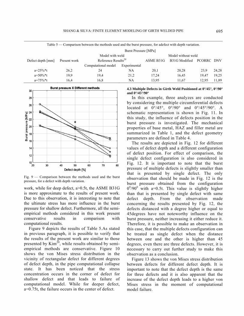
work, while for deep defect, a>0.5t, the ASME B31G is more approximate to the results of present work. Due to this observation, it is interesting to note that the ultimate stress has more influence in the burst pressure for shallow defect. Furthermore, all the semi-empirical methods considered in this work present conservative results in comparison with computational results.
Figure 9 depicts the results of Table 5.As stated in previous paragraph, it is possible to verify that the results of the present work are similar to those presented by Kim20, while results obtained by semi-empirical methods are conservative. Figure 10 shows the von Mises stress distribution in the vicinity of rectangular defect for different degrees of defect depth, in the pipe computational collapse state. It has been noticed that the stress concentration occurs in the corner of defect for shallow defect and that leads to failure of computational model. While for deeper defect, a=0.75t, the failure occurs in the center of defect.
4.3 Multiple Defects in Girth Weld Positioned at 0°/45°, 0°/90° and 0°/45°/90°
In this example, three analyzes are conducted by considering the multiple circumferential defects located at 0°/45°, 0°/90° and 0°/45°/90°. A schematic representation is shown in Fig. 11. In this study, the influence of defects position in the burst pressure is investigated. The mechanical properties of base metal, HAZ and filler metal are summarized in Table 1, and the defect geometry parameters are defined in Table 4.
The results are depicted in Fig. 12 for different values of defect depth and a different configuration of defect position. For effect of comparison, the single defect configuration is also considered in Fig. 12. It is important to note that the burst pressure of multiple defects is slightly smaller than that is presented by single defect. The only observation that should be made in Fig. 12 is the burst pressure obtained from the configuration 00/900 with a=0.5t. This value is slightly higher than that is presented by single defect with same defect depth. From the observation made concerning the results presented by Fig. 12, the defects distanced with a degree higher or equal to 45degrees have not noteworthy influence on the burst pressure, neither increasing it either reduce it. Therefore, it is possible to make an observation in this case, that the multiple defects configuration can be treated as single defect when the distance between one and the other is higher than 45 degrees, even there are three defects. However, it is necessary to carry out further study to make this observation as a conclusion.
Figure 13 shows the von Mises stress distribution between defects for different defect depth. It is important to note that the defect depth is the same for three defects and it is also apparent that the increase of the defect depth leads to a higher von Mises stress in the moment of computational model failure.
Table 5 — Comparison between the methods used and the burst pressure, for adefect with depth variation.
Burst Pressure [MPa] Model with weld Model without weld
Defect depth [mm] Present work Reference Results20 ASME B31G B31G Modified PCORRC DNV Computational model Experimental
a=25%*t 26,2 24 NA 20,1 20,28 23,9 24,28 a=50%*t 19,9 19,4 21,2 17,24 16,45 19,47 19,25 a=75%*t 16,4 16,8 NA 13,95 11,67 12,95 11,89
Fig. 9 — Comparison between the methods used and the burstpressure, for a defect with depth variation.

INDIAN J ENG MATER SCI, JUNE 2020
696
Fig. 10 — Distribution of Von Mises equivalent stressfor different values of defect depth (a)a = 25% * t = 3.97 mm, (b) a = 50% * t =7.95 mm and (c) a = 75% * t = 11.92 mm.
Fig. 11 — Defect positioned at 0° and 45°, 0° and 90°, 0°, 45°and 90° with a variation of defect depth.
Fig. 12 — Comparison of burst pressure versus defect position at 0°, 0°& 45° and 0° & 90°.

SHANG & SILVA: FINITE ELEMENT MODELING OF GIRTH WELDED PIPE
697
5 Conclusions In the present work, a computational model is
developed by the finite element method for the assessment of burst pressure in welded pipes with corrosion. The contact conditions between base metal, additional material, and heat-affected zone are considered in the model, as well as the elastoplastic behavior of the material, which is analyzed by von Mises isotropic hardening model. The physical nonlinearity present in this work is solved by Newton - Raphson method. The results obtained are compared to the experimental and computational results of Kim20and show the competitiveness of present computational model. The results are also compared to semi-empirical methods such as ASME B31G, MODIFIED B31G, PCORRC, and DNV. With the results obtained from the analysis varying the HAZ width, it can be stated that the heat-affected zone, with a width ranging between 0% and 100% of the pipe wall thickness, has no significant influences on the burst pressure value.
In the analysis of the welded pipe with single defect, the burst pressure is determined for different values of defect depth. A comparison is made between the present work results and the semi-empirical methods. The ASME B31G and B31G modified methods present conservative results. While
the PCORRC and DNV methods, that employ ultimate stress in the criteria, have obtained a burst pressure approximately equal to the present computational model. Especially in the cases where the defect depth equal to 25% and 50% of pipe wall thickness. However, for the defect depth equal to 75% of pipe wall thickness, the PCORRC and DNV methods are also conservative.
For the welded pipes with multiple defects, an analysis is carried out by varying the defect depth for different defects position in the circumferential direction. The assessed burst pressures lead to an observation that these multiple defects could be treated as single defect when the distance between the defects is higher or equal to 45 degrees. Because there is not a substantial variation in the burst pressure by using the mechanical and geometrical parameters adopted in this work. References 1 National Agency of Petroleum, Brazilian statistical yearbook
of natural gas and biofuel, (National Agency of Petroleum), 2019, p. 15.
2 Chen H F & Shu D, Eng Struct, 23 (2001) 207. 3 Meliani M H, Matvienko Y G & Pluvinage G, Eng Failure
Analysis, 18 (2011) 271. 4 Mutas V V, Trebskii M A & Rabkina M D, Strength Mater,
44 (2012) 574.
Fig. 13 — Distribution of von Mises stressfor different value of defect depth at 0°, 45° & 90° (a) a = 25% * t = 3.97 mm, 0/45/90 degrees,(b) a = 50% * t = 7.95 mm, 0/45/90 degrees and (c) a = 75% * t = 11.92 mm, 0/45/90 degrees.

INDIAN J ENG MATER SCI, JUNE 2020
698
5 Abdalla Filho J E, Machado R D,Bertin R J & Valentini M D, Comp Struct, 132 (2014) 22.
6 Kim Y J & Son B G, Int J Pres Ves Piping, 81 (2004) 897. 7 Chiodo M S & Ruggieri C, Int J Pres Ves Piping, 86 (2009) 164. 8 Choi J B, Goo B K, Kim J C, Kim Y J & Kim W S, Int J
Pres Ves Piping, 80 (2003) 121. 9 Kim Y J, Shim D J & Huh N S, Int J Pres Ves Piping, 79
(2002) 321. 10 Zhu X K & Leis B N, Int J Pres Ves Piping, 83 (2006) 666. 11 Yeom K J, Young K L, Oh K H & Kim W S, Eng Failure
Analysis, 57 (2015) 553. 12 Ma B, Shuai J, Liu D & Xu K, Eng Failure Analysis, 32
(2013) 209. 13 Fekete G & Varga L, Eng Failure Analysis, 21 (2012) 21. 14 Chen Y, Zhang H, Zhang J, Liu X, Li X & Zhou J, Eng
Failure Analysis, 47 (2015) 67. 15 Silva R C C, Guerreiro J N C & Loula A F D, Adv Eng
Software, 38 (2007) 868. 16 Zhang H, Chen Y, Zhang J, Li X & Zhou J, Mat Des, 67
(2015) 552. 17 Motta R S, Cabral H L D, Afonso S M B, Willmersdorf R B,
Bouchonneau N, Lyra P R M & Andrade E Q, Eng Failure Analysis, 81 (2017) 178.
18 Hsu Y S, Acta Scientiarum, 38 (2016) 313. 19 Hertelé S, Cosham A & Roovers P, Eng Struct, 70 (2016) 375. 20 Kim W S, Yeom K J & Oh K H, Eng Failure Analysis, 70
(2016) 375.
21 ASME, Manual for Determining the Remaining Strength of Corroded Pipelines – A Supplement to ASME B31 Code for Pressure Piping (The American Society of Mechanical Engineers, USA), ISBN: 9780791834480 (2012) 30.
22 DNV, DNV Recommended Practice – DNV–RP–F101 - Corroded Pipelines (Det Norske Veritas, Norway) (2010) 5.
23 Bathe K J, Finite Element Procedures (Prentice-Hall, New Jersey), 1st Edn, ISBN: 0 – 13 – 301458 – 4 (1995) 435.
24 Dhatt G & Touzot G, The Finite Element Method Displayed (John Wiley & Sons, Great Britain). 1st Edn, ISBN: 0-471-90110-5 (1987) 156.
25 Moveni S, Finite Element Analysis, Theory and Application with ANSYS (Prentice-Hall, Mankato), 1st Edn, ISBN: 0-13-785098-0 (1999) 135.
26 Zienkiewicz O C & Taylor R L, The Finite Element Method for Solid and Structural Mechanics (McGraw-Hill, Great Britain), 6th Edn, ISBN: 0-7506-6321-9 (2005) 235.
27 Ostby E, Jayadevan K R & Thaulow C, Int J Pres Ves Piping, 82 (2005) 201.
28 Jia P, Jing H, Xu L, Han Y & Zhao L, Int J Mec Sci, 58 (2016) 23.
29 Zhang Y, Lie S T & Zhao H S, Marine Struc, 58 (2018) 92. 30 Paredes M & Ruggieri C, Int J Pres Ves Piping, 125 (2015)
49. 31 Souza R F, Ruggieri C & Zhang Z, Eng Frac Mec, 163
(2016) 66.