finite element analysis of shaft using … 1675 finite element analysis of shaft using composite...
TRANSCRIPT

Page 1675
Finite Element Analysis of Shaft Using Composite Materials
Without and With Damping
Mohd.Azharuddin
P.G. Student,
Department of Mechanical Engineering,
Malla Reddy College of Engineering,
Hyderabad, India.
C.Shashikanth
Assistant Professor,
Department of Mechanical Engineering,
Malla Reddy College of Engineering,
Hyderabad, India.
Abstract:
High-technology structures often have stringent
requirements for structural dynamics. Suppressing
vibrations is crucial to their performance. Passive
damping is used to suppress vibrations by reducing
peak resonant response. Viscoelastic damping
materials add passive damping to structures by
dissipating vibration strain energy in the form of heat
energy. The incorporation of damping materials in
advanced composite materials offers the possibility of
highly damped, light-weight structural components
that are vibration-resistant. The aim of the project is
to analyze the shaft without damping material and
with damping material. The present used material for
shaft is steel. In this thesis, the composite materials
considered are HM Carbon Epoxy and HS Carbon
Epoxy. The material for damping is rubber. The
structural analysis is done to verify the strength of
the shaft and compare the results for three materials.
Modal analysis is done on the shaft to determine
mode shapes.
Analysis is done in Ansys.
KEYWORDS: Modelling, Analysis, Ansys
1. INTODUCTION
A driveshaft is a rotating shaft that transmits power
from the engine to the differential gear of a rear wheel
drive vehicles Driveshaft must operate through
constantly changing angles between the transmission
and axle. High quality steel (Steel SM45) is a common
material for construction. Steel drive shafts are usually
manufactured in two pieces to increase the
fundamental bending natural frequency because the
bending natural frequency of a shaft is inversely
proportional to the square of beam length and
proportional to the square root of specific modulus.
The drive shaft is generally composed by the main
gear box, differential, wheels, transmission and drive
shaft shell. Its role is cardan transmission power
coming folded over an angle of 90 ° to change the
direction of transmission of force by the main reducer
to reduce the speed, to increase the torque, after
differential assigned to the left and right axle and drive
round.
1.1: A truck propeller shaft
METHADOLOGY
The 2D model of shaft reinforcement is made in
PROE. After that is imported into wokbench for
analysis. Stress and deformation is observed. We are
applied force on shaft for calculating deformations.
Now by using Newton’s second law, we calculated
force value according to respected speeds for

Page 1676
respective materials. This point force applied centrally
on Shaft.
MATERIAL SELECTION
Three types of material are selected for shaft mainly
following specification:
MODELLING OF SHAFT
DIFFERENT MODULES IN PRO/ENGINEER
PART DESIGN
ASSEMBLY
DRAWING
SHEETMETAL
MANUFACTURING
EXPERIMENTAL PROCEDURE
4.3 SHELL ELEMENT - STRUCTURAL
ANALYSIS
4.3.1 WITH DAMPING MATERIAL (RUBBER)
MATERIAL – STEEL (SM 45 C)
TOTAL DEFORMATION
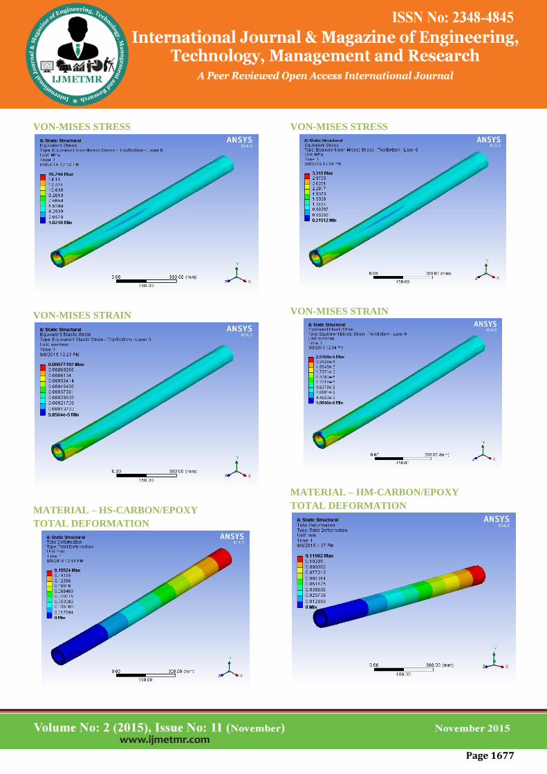
Page 1677
VON-MISES STRESS
VON-MISES STRAIN
MATERIAL – HS-CARBON/EPOXY
TOTAL DEFORMATION
VON-MISES STRESS
VON-MISES STRAIN
MATERIAL – HM-CARBON/EPOXY
TOTAL DEFORMATION
Page 1678
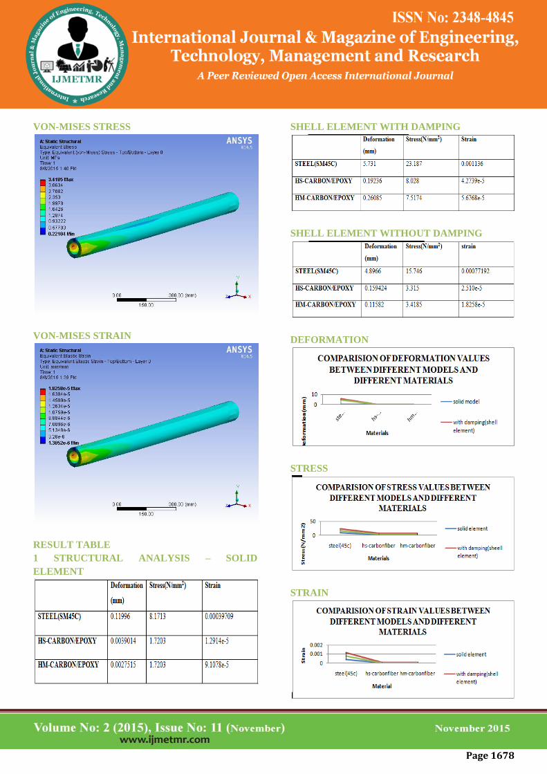
VON-MISES STRESS
VON-MISES STRAIN
RESULT TABLE
1 STRUCTURAL ANALYSIS – SOLID
ELEMENT
SHELL ELEMENT WITH DAMPING
SHELL ELEMENT WITHOUT DAMPING
DEFORMATION
STRESS
STRAIN

Page 1679
MODAL ANALYSIS – SOLID ELEMENT
SHELL ELEMENT WITHOUT DAMPING
RESULTS
SHELL ELEMENT WITH DAMPING
Page 1680
CONCLUSION
In this thesis shaft is analyzed without damping
material and with damping material. The present used
material for shaft is steel. In this thesis, the composite
materials considered are HM Carbon Epoxy and HS
Carbon Epoxy. The composite materials are
considered due to their high strength to weight ratio.
The material for damping is rubber.
The structural analysis is done to verify the strength of
the shaft and compare the results for three materials.
By observing the analysis results, the stress values are
less when composite material Carbon Epoxy is used
when compared with that of Steel.
Structural analysis is also done on the shaft using shell
element without damping material and with damping
material rubber. The stresses are more when damping
material is used than without damping material but the
stresses are within the range. By using damping
material strength increases in the shaft thereby
decreasing vibrations.
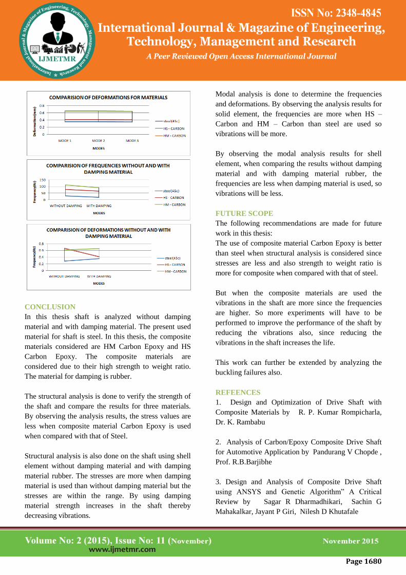
Modal analysis is done to determine the frequencies
and deformations. By observing the analysis results for
solid element, the frequencies are more when HS –
Carbon and HM – Carbon than steel are used so
vibrations will be more.
By observing the modal analysis results for shell
element, when comparing the results without damping
material and with damping material rubber, the
frequencies are less when damping material is used, so
vibrations will be less.
FUTURE SCOPE
The following recommendations are made for future
work in this thesis:
The use of composite material Carbon Epoxy is better
than steel when structural analysis is considered since
stresses are less and also strength to weight ratio is
more for composite when compared with that of steel.
But when the composite materials are used the
vibrations in the shaft are more since the frequencies
are higher. So more experiments will have to be
performed to improve the performance of the shaft by
reducing the vibrations also, since reducing the
vibrations in the shaft increases the life.
This work can further be extended by analyzing the
buckling failures also.
REFEENCES
1. Design and Optimization of Drive Shaft with
Composite Materials by R. P. Kumar Rompicharla,
Dr. K. Rambabu
2. Analysis of Carbon/Epoxy Composite Drive Shaft
for Automotive Application by Pandurang V Chopde ,
Prof. R.B.Barjibhe
3. Design and Analysis of Composite Drive Shaft
using ANSYS and Genetic Algorithm” A Critical
Review by Sagar R Dharmadhikari, Sachin G
Mahakalkar, Jayant P Giri, Nilesh D Khutafale
Page 1681
4. Design And Dynamic Analysis Of Viscoelastic
Structures For Propellar Shaft by Davidclaude
Gollapudi P.Veera Raju
5. Design and Analysis of Composite Material Drive
Shaft by Chaitanya G Rothea, A.S.Bombatkarb
6. Material Optimization and Weight Reduction of
Drive Shaft Using Composite Material Harshal
Bankar, Viraj Shinde, P. Baskar
7. Design, Static and Modal Analysis of A Propeller
Shaft for Reducing Vibrations Using Composite
Damping by Srimanthula Srikanth, Jithendra
Bodapalli, Avinash Gudimetla
8. Design And Analysis Of Composite Drive Shaft By
V. S. Bhajantri, S. C. Bajantri, A. M. Shindolkar, S. S.
Amarapure
9. Damping of Composite Material Structures with
Riveted Joints by Nikhil Chinthapatla.