finite element analysis of reinforced...
TRANSCRIPT
Global J. of Engg. & Appl. Sciences, 2013: 3 (1)
72 ISSN 2249-2631(online): 2249-2623(Print) - Rising Research Journal Publication
Research Paper: Chivende et al., 2013: Pp.72-80
FINITE ELEMENT ANALYSIS OF REINFORCED CONCRETE ARC BRIDGES SUBJECTED TO MORE THAN 30 TONES MONOTONIC LOADS IN ZIMBABWE
Duncan. R. Chivende., Tawanda Mushiri* and Talon Garikayi
Dept. of Mechatronics, Chinhoyi University of Technology P.O Box 7724 Chinhoyi, Zimbabwe *Dept. of Mechanical Engineering, University of Zimbabwe, P.O Box MP167, Mt Pleasant, Harare, Zimbabwe
Corresponding author: [email protected].
ABSTRACT Several methods have been utilized to study the response of RC structural components. Experimental based testing has been widely used as a means to analyze individual elements and the effects of concrete strength under loading in civil engineering. In this case the use of FEA to study these RC arc bridges has been used. This project deals with determining of stresses in rein forced arc bridges in Zimbabwe tested when subjected to more than 30 tones load. Finite element program for analysis of RC concrete arc bridges and three-dimensional meshed frames are developed and implemented in Autodesk Inventor environment. This developed program determines efficiently the combined state of stresses at any cross-section of a 3D frame, crushing or cracking of RC takes place when the strains lie outside the ultimate surface in the biaxial strain space. The static non linear analysis is done to find out ultimate capacity, formation of first crack and its distance from support, initiation of diagonal crack and its distance from support. Key words: RC- Reinforced Concrete, Arc bridges, FEA- Finite Element Analysis and Autodesk inventor software.
INTRODUCTION Reinforced concrete (RC) has become one of the most important building materials and is widely used in many types of civil engineering structures which include the construction arc bridges. These arc bridges are subjected to suddenly change in occurrence of stress and strain when vehicle pass through the bridge (monotonic loads). So as concern the researcher is focusing on the FEA of the arc bridges in Zimbabwe subjected to more than 30 tones loads vehicle and also the study mainly focus on the main effects of these loads to arc bridges (Balakrishnan and Murray, 1988). The RC arc bridges must satisfy the following conditions:
The structure must be strong and safe: Any RC structure designed under the laws of equilibrium and the consideration of the mechanical properties of the structure should result in a sufficient margin of safety against collapse under accidental overloads. The structure must be stiff and appear unblemished: Care must be taken to control deflections under service loads and to limit the crack width to an acceptable level.
The ultimate objective of design is the creation of a safe and economical structure. Advanced analytical tools can be an indispensable aid in the assessment of the safety and the serviceability of a proposed design. The safety and serviceability assessment of these structures necessitates the development of accurate and reliable methods and models for their analysis. In this case the researcher proposed the FEA under Autodesk Inventor software which is using cheap, easy and accuracy as compared with currently used experimental primitive analysis methods. Intimately related to the increase in scale of modern structures is the extent and impact of disaster in terms of human and economical loss in the event of structural failure. As a result, careful
and detailed structural safety analysis becomes more and more necessary (Barzegar and Schnobrich, 1986).
The finite element method is a general method of structural analysis in which the solution of a problem in continuum mechanics is approximated by the analysis of an assemblage of finite elements which are interconnected at a finite number of nodal points and represent the solution domain of the problem. A similar acceptance in nonlinear analysis problems depends on two major factors which are: The increase in computational effort which is required for nonlinear problems necessitate that considerable computing power be available at low cost to the designer and the second major factor is related to the level of complexity of nonlinear analysis.
The development of improved elementary characteristics and more efficient nonlinear solution algorithms as well as the experience gained in their application to engineering problems, ensured that nonlinear finite element analysis can now be performed with some confidence. Thus, barriers to the wide use of nonlinear finite element techniques are gradually removed. Thus the application of the FEA in the behaviour of RC arc bridges since that, RC is nonlinear behaviour under heavy loads and is widely used in many constructions which include the construction of arc bridges. Most of bridge structures are usually designed to carry loads, so as concern the researcher will explore the application of FEA to test the strength of arc span of a bridge, to avoid accident of a bridge failure which may cause accidents. The concern of this study is an important in Zimbabwe to analyze the effect of overloading bridges because most of the arc bridges in
Global J. of Engg. & Appl. Sciences, 2013: 3 (1)
73 ISSN 2249-2631(online): 2249-2623(Print) - Rising Research Journal Publication
Zimbabwe are condemned due to high risk of safety and cracks developed.
Aim: The main aim of this project is to demonstrate the finite element analysis on the effect of 30 tones monotonic loads on reinforced concrete arc bridges in Zimbabwe. Problem statement More than 30 tonnes heavy vehicles in Zimbabwe are causing nonlinear material behaviour of concrete and steel on arc bridges, cracking of reinforced concrete and time dependent effects such as creep and shrinkage.
OBJECTIVES The main objectives of this study are: To investigate the effect of material and
numerical parameters, such as tensile strength, stresses and strain forces on the response of reinforced concrete arc bridges
To develop software system which investigate the mainly affected areas by 30 tones monotonic load on arc bridges
Scope of the study: The present investigation of the nonlinear response to failure of RC structures under short term monotonic loads was initiated with the intent to investigate the relative importance of several factors in the nonlinear finite element analysis of RC structures. These include the effect of tension-stiffening and bond-slip and their relative importance on the response of under- and over-reinforced beams, piers, and the effect of size of the finite element mesh on the analytical results and the effect of the nonlinear behaviour of concrete and steel on the response of overloads which exceeds 30 tones. In the progress of this study improved material models were developed and included in the analysis.
Justification: It is very important for reinforced concrete structures such as bridges, dams and building to implement Finite Element methods. This is important for more accurate to determine the strength of the structure because these structures deals with human life. The civil engineer can predict the safety factor of the structure according to the load that can be sustained by the structure. The analysis of creep-damage processes is becoming more and more important in civil engineering practice due to the fact that the exploitation condition like temperature and pressure is increasing while the weight of the structure should decrease. In the same time the safety standards are increasing too. Analyzed arc bridges made up of 3-dimensional elements with layered cross sections which accounted for progressive cracking and changing material properties through the depth of the cross section as a function of load and time. The use FEA analysis will explore the safety factor and warning before the bridge failure to avoid accidents and lose of life.
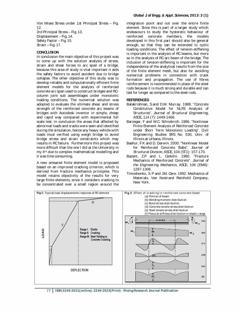
The typical stages in the load-deformation behaviour of a reinforced concrete simply supported beam are illustrated in Figure 1. Similar relations are obtained for other types of RC structural elements. This highly nonlinear response can be roughly divided into three ranges of behaviour: the un cracked elastic stage, the crack propagation and the plastic (yielding or crushing) stage. The final cracking state is reached when a tensile force of sufficient magnitude to form an additional crack between two existing cracks can no longer be transferred by bond from steel to concrete Figure. 2c, 2d and 2e show the idealized distribution between cracks of bond stress, concrete tensile stress and steel tensile stress, respectively. Because concrete is carrying some tension between the cracks, the flexural rigidity is clearly greater between the cracks than at the cracks, as shown in Figure 2f (Park, 1995).
RESULTS AND DISCUSSION The physical behaviour in the vicinity of a crack can be inferred from Figure 2d and Figure 2e. As the concrete reaches its tensile strength, primary cracks form. The number and the extent of cracks are controlled by the size and placement of the reinforcing steel. At the primary cracks the concrete stress drops to zero and the steel carries the entire tensile force. The concrete between the cracks, however, still carries some tensile stress, which decreases with increasing load magnitude. This drop in concrete tensile stress with increasing load is associated with the breakdown of bond between reinforcing steel and concrete. At this stage a secondary system of internal cracks, called bond cracks, develops around the reinforcing steel, which begins to slip relative to the surrounding concrete. REINFORCING STEEL ON BEAM CROSS MEMBER Behaviour of Reinforcing Steel: The properties of reinforcing steel, unlike concrete, are generally not dependent on environmental conditions or time. Thus, the specification of a single stress-strain relation is sufficient to define the material properties needed in the analysis of reinforced concrete structures (Fig 3).
Typical stress-strain curves for reinforcing steel bars used in concrete construction are obtained from coupon tests of bars loaded monotonically in tension. For all practical purposes steel exhibits the same stress-strain curve in compression as in tension. The steel stress-strain relation exhibits an initial linear elastic portion, a yield plateau, a strain hardening range in which stress again increases with strain and, finally, a range in which the stress drops off until fracture occurs. The extent of the yield plateau is a function of the tensile strength of steel. High-strength, high-carbon steels, generally, has a much shorter yield plateau than relatively low-strength, low-carbon steels (Timoshenko and Gere, 1992).
Global J. of Engg. & Appl. Sciences, 2013: 3 (1)
74 ISSN 2249-2631(online): 2249-2623(Print) - Rising Research Journal Publication
BOND BETWEEN REINFORCING STEEL AND CONCRETE Bond Behaviour: Bond is the interaction between reinforcing steel and surrounding concrete. The force transfer from steel to concrete can be attributed to three different phenomena: chemical adhesion between mortar paste
and bar surface; friction and wedging action of small dislodged sand particles between the bar
and the surrounding concrete Mechanical interaction between concrete
and steel. Bond of plain bars derives primarily from the first two mechanisms, even though there is some mechanical interlocking caused by the roughness of the bar surface. Deformed bars have better bond than plain bars, because most of the steel force is transferred through the lugs to concrete. Friction and chemical adhesion forces are not negligible, but secondary and tend to decrease as the reinforcing bars start to slip. Since bond stresses in reinforced concrete members arise from the change in the steel force along the length, the effect of bond becomes more pronounced at end anchorages of reinforcing bars and in the vicinity of cracks (Fig 4).
Bond of plain bars derives primarily from the first two mechanisms, even though there is some mechanical interlocking caused by the roughness of the bar surface. Deformed bars have better bond than plain bars, because most of the steel force is transferred through the lugs to concrete. Friction and chemical adhesion forces are not negligible, but secondary and tend to decrease as the reinforcing bars start to slip. Since bond stresses in reinforced concrete members arise from the change in the steel force along the length, the effect of bond becomes more pronounced at end anchorages of reinforcing bars and in the vicinity of cracks. In the simplified analysis of reinforced concrete structures complete compatibility of strains between concrete and steel is usually assumed, which implies perfect bond. This assumption is realistic only in regions where negligible stress transfer between the two components takes place. In regions of high transfer stresses along the interface between reinforcing steel and surrounding concrete, such as near cracks, the bond stress is related to the relative displacement between reinforcing steel and concrete. The assumption of perfect bond near crack zones requires infinitely high strains to explain the existence of a finite crack width. In reality there is no strain compatibility between reinforcing steel and surrounding concrete near cracks. This incompatibility and the crack propagation give rise to relative displacements between steel and concrete, which are known as bond-slip (Macnith, 1990).
CROSS-SECTIONAL OF RC BEAM Typical cross-sectional properties of a composite beam are defined as follows. Weighted area of the cross-section is EA = ∫A EdA…....Equation2.4 Weighted first moments of area are (ES)y = ∫A EzdA Equation 2.5 (ES)z = ∫ EydA…..Equation 2.6 Bending stiffness’s or weighted second moments of area are (EI)y = ∫A Ez dA Equation 2.7 (EI)z = ∫ Ey dA …Equation 2.8 (EI) yz = ∫A EyzdA..Equation 2.9 TENSION / COMPRESSION OF THE RC BEAM In beam theory, a beam under tension or compression only produces normal stress in the axial direction, σx. Using Hooke’s law, this stress is σx = Eεx …….Equation 2.10 where εx is the axial strain of the beam. Using the definition of the axial force x N becomes: Nx = ∫Aσ dA =∫ AEε dA = EAεx…Equation 2.11 EXPERIMENTAL STUDY OF RC USED ON ARC BRIDGE
The experimental tests were carried out on un-notched RC arc beams by Carpinteri at the Department of Structural Engineering of Politecnico di Torino (Carpinteri 1998). Several reinforced concrete beams of rectangular cross-section varying in depth from 100 mm to 800 mm were tested in order to closely observe the minimum reinforcement requirement and its dependency to the beam depth. Only his four 100-mm depth beams with steel reinforcement ratio. ρ = 0.085%, 0.256%, 0.653%, and 1.003%, namely B1, B2, B3, and B4, respectively, are studied here. The beams have one layer of longitudinal reinforcement and there is no shear reinforcement. CRACKS IN RC ARC SPAN CONCRETE MODEL Concrete crack plots were created at different load levels to examine the different types of cracking that occurred within the concrete as shown in Figure 5. The different types of concrete failure that can occur are flexural cracks, compression failure (crushing), and diagonal tension cracks. Flexural cracks (Figure 5a) form vertically up the beam. Compression Failures (Figure 5b) are shown as circles. Diagonal tension cracks (Figure 5c) form diagonally up the beam towards the loading that is applied. Crack develops in concrete element when the concrete element stress exceeds modulus of rupture of concrete (tensile strength of concrete). Crash develops in concrete element when the concrete element stress exceeds compressive crashing strength of concrete. This study indicates that the use of a finite element program to model experimental data is viable and the results that are obtained can indeed model reinforced concrete beam behaviour reasonably well (Fig 5).
Global J. of Engg. & Appl. Sciences, 2013: 3 (1)
75 ISSN 2249-2631(online): 2249-2623(Print) - Rising Research Journal Publication
FAILURE CRITERIA FOR RC ARC SPAN OF A BRIDGE The model is capable of predicting failure for concrete materials. Both cracking and crushing failure modes are accounted for. The two input strength parameters i.e., ultimate uni-axial tensile and compressive strengths are needed to define a failure surface for the concrete. Consequently, a criterion for failure of the concrete due to a multi-axial stress state can be calculated (William and Warnke 1995). A three-dimensional failure surface for concrete is shown in Figure 6.
FAILURE SURFACE OF RC CONCRETE OF ARC SPAN OF A BRIDGE Finite Element Modeling of Steel Reinforcement Tavarez (2001) discusses three techniques that exist to model steel reinforcement in finite element models for reinforced concrete is shown in Figure 7: the discrete model, the embedded model, and the smeared model.
PLASTICITY MODEL FOR STEEL REINFORCEMENT In this study, Von Mises yield criterion (Figure 16) with “isotropic hardening” rule (see e.g. Kachanov 1974, Johnson and Mellor, Owen and Hinton 1980) is used in the modelling of steel reinforcement. The steel reinforcement is modelled as one-dimensional elasto-plastic material with a linear hardening parameter. This model is available in the FE program LUSAS (LUSAS User Manual 2001). The steel reinforcement is represented by bar elements and then connected to concrete elements. In LUSAS, the location of the steel elements needs to lie at the element boundaries by fixing node to node. The overall stiffness matrix of the reinforced concrete would then be made up of two components, the concrete element component and the reinforcement component. It is assumed that there is perfect bond between the steel reinforcement and concrete.
PLASTICITY MODEL FOR COMPRESSIVE RC CONCRETE OF ARC SPAN OF A BRIDGE In the Multi-crack model (Jefferson 1999), the compressive behaviour is assumed linear elastic. This section presents the plasticity component for modelling compressive concrete used in Craft model. In this model, a smooth triaxial yield surface is developed from the yield function used by Lubliner et al. (1989) and from Willam and Warnke’s (1995) smoothing function. The model has yield function meridians and yield function on the π-plane. The model includes friction hardening and softening to account for pre- and post-peak non-linear behaviour, and uses work hardening in which the total work required to reach the peak stress envelope is made a function of the mean stress. The model is developed with a dilatancy parameter that allows plastic flows to be associated or non-associated. Moreover, in the model, the local responses from all active plastic surfaces are
coupled in a multi-surface plasticity formulation, which provides the interaction between compressive and tensile behaviour. Thus, the crushing effects to the structural behaviour can be captured. However, as the model does not simulate non-linearity under hydrostatic compression and the yield function has straight meridians, the accuracy of the model reduces for stress states with high triaxial confinement.
FRACTURE AND DAMAGE MODELS FOR RC CONCRETE IN TENSION A plastic fracture approach has been used in modelling concrete in tension. A model based on this approach, namely Multi-crack model, was developed by Jefferson (1999) and has been incorporated into the program LUSAS (LUSAS Manual 2001) which is used in this research. The model is a further development of a Multi-crack plasticity approach proposed by Carol and Bazant (1995) and in the model, the procedure developed for modelling cracks is similar to the non-orthogonal fixed smeared crack model presented by de Borst and Nauta (1985) and Rots (1988). It should be noted that in this Multi-crack model, tensile cracking is accounted for but crushing failure in compression is neglected. Also, in this model, linear elastic behaviour is employed for concrete in compression.
METHODOLOGY Finite element analysis approach (incremental method from 30 tones): An analysis and a numerical computer program will be developed for analyzing the stresses and creep in an arbitrary symmetric of revolution subjected to ax symmetric loads. The method of solution is an extension of the direct stiffness method. The body is replaced by a system of discrete triangular cross section ring elements interconnected along circumferential nodal circles. The equation of equilibrium for the reinforced concrete is derived from the principal of minimum potential energy. These creep strains are treated as initial strains to determine the new stress distribution at the end of the time increment. The procedure is repeated either until the final time is reached or until the stress distribution becomes constant i.e. a steady-state condition is reached.
The following steps are going to be used during the design and the analysis the behaviour of RC concrete of arc cross member of a bridge under monotonic load. The researcher is only focusing on the sample of a RC cross arc beams under monotonic load. The structure of the arc beam is very important because it carries the whole load of the structure and of vehicles. The major point on the analysis will be on the maximum stress and strain of the beam. On the design the researcher is going to select the small rectangle of the whole structure which consists of reinforced rod as the supporting member of the beam to increase the strength of the beam.
Global J. of Engg. & Appl. Sciences, 2013: 3 (1)
76 ISSN 2249-2631(online): 2249-2623(Print) - Rising Research Journal Publication
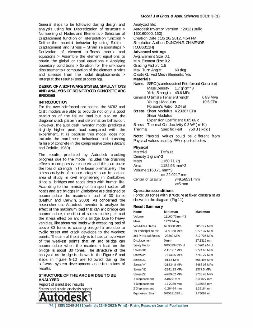
General steps to be followed during design and analysis using fea: Discretization of structure > Numbering of Nodes and Elements > Selection of Displacement function or interpolation function > Define the material behavior by using Strain – Displacement and Stress – Strain relationships > Derivation of element stiffness matrix and equations > Assemble the element equations to obtain the global or total equations > Applying boundary conditions > Solution for the unknown displacements > computation of the element strains and stresses from the nodal displacements > Interpret the results (post processing).
DESIGN OF A SOFTWARE SYSTEM, SIMULATIONS AND ANALYSIS OF REINFORCED CONCRETE ARC BRIDGES
INTRODUCTION For the over-reinforced arc beams, the MC82 and Craft models are able to provide not only a good prediction of the failure load but also on the diagonal crack pattern and deformation behaviour. However, the auto desk inventor model predicts a slightly higher peak load compared with the experiment. It is because this model does not include the non-linear behaviour and crushing failure of concrete in the compressive zone (Bazant and Cedolin, 1980).
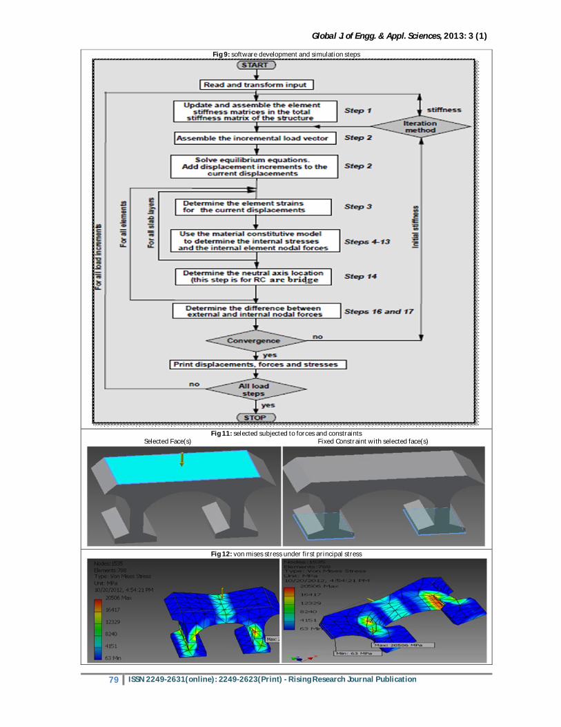
The results predicted by Autodesk cracking progress due to the model includes the crushing effects in compressive concrete and this can cause the loss of strength in the beam prematurely. The stress analysis of an arc bridges is an important area of study in civil engineering in Zimbabwe, since all bridges and roads deals with human life. According to the ministry of transport sector, all roads and arc bridges in Zimbabwe are designed to accommodate the maximum load of 30 tones (Bashur and Darwin, 2000). As concerned the researcher use Autodesk inventor to analyze the effect of the maximum load that can arc bridge can accommodate, the effect of stress to the pier and the stress effect on arc of a bridge. Due to heavy vehicles, like abnormal loads with exceeding load of above 30 tones is causing bridge failure due to cyclic stress and crack develops to the weakest points. The aim of the study is to have an overview of the weakest points that an arc bridge can accommodate when the maximum load on the bridge is about 30 tones. The structure of the analyzed arc bridge is shown in the Figure 8 and steps in figure 9-10 are followed during the software system development and simulations of results.
STRUCTURE OF THE ARC BRIDGE TO BE ANALYSED Report of simulated results Stress and strain analysis report
Analyzed file: Autodesk Inventor Version : 2012 (Build 160160000, 160) Creation Date : 10/20/2012, 4:54 PM Simulation Author: DUNCAN.R. CHIVENDE [CO86311H] Advanced settings Avg. Element Size: 0.1 Min. Element Size: 0.2 Grading Factor: 1.5 Max. Turn Angle: 60 deg Create Curved Mesh Elements: Yes Materials Name: SSRC (stainless steel Reinforced Concrete) Mass Density 1.7 g/cm^3 Yield Strength 49.6 MPa General Ultimate Tensile Strength 6.89 MPa Young's Modulus 10.5 GPa Poisson's Ratio 0.24 ul Stress Shear Modulus 4.23387 GPa Shear Modulus Expansion Coefficient 0.05 ul/c Stress Thermal Conductivity 0.3 W/( m K ) Thermal Specific Heat 750 J/( kg c )
Note: Physical values could be different from Physical values used by FEA reported below:
Physical Material Default Density 1 g/cm^3 Mass 1160.71 kg Area 1182.93 mm^2 Volume 1160.71 mm^3 x=-22.0217 mm Center of Gravity y=9.56531 mm z=5 mm
Operations conditions Force: 30 tones with structure at fixed constraint as shown in the diagram (Fig 11)
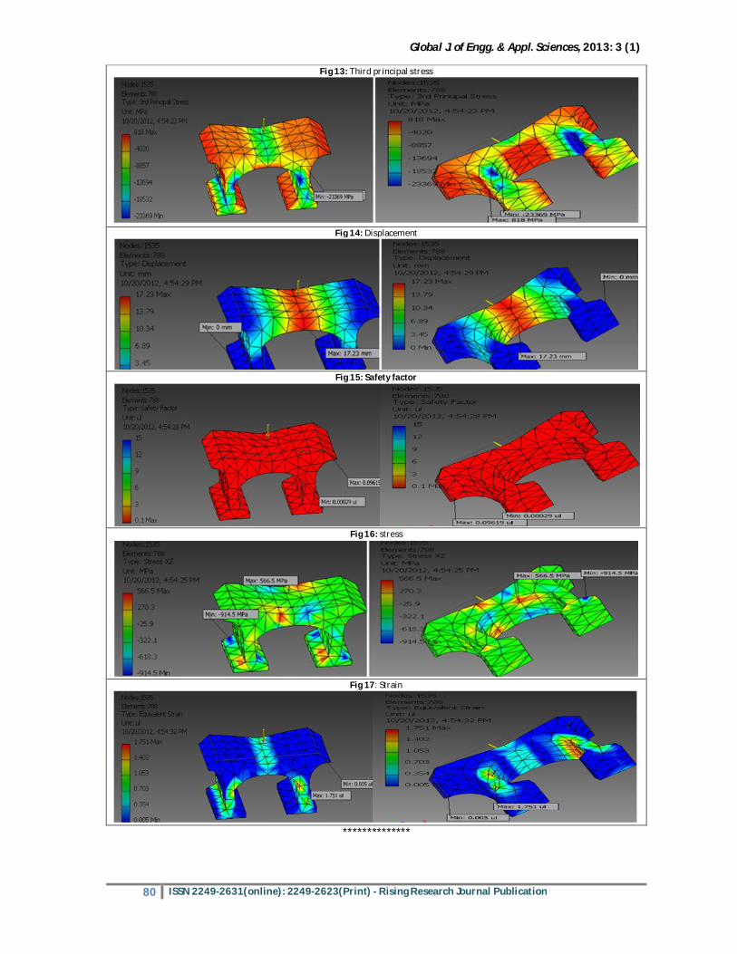
Result Summary Name Minimum Maximum Volume 11160.73 mm^3 Mass 1973.24 kg Von Mises Stress 62.8888 MPa 20505.7 MPa 1st Principal Stress -3391.58 MPa 9775.37 MPa 3rd Principal Stress -23369 MPa 817.735 MPa Displacement 0 mm 17.2316 mm Safety Factor 0.000294835 ul 0.0961944 ul Stress XX -11519.7 MPa 9774.68 MPa Stress XY -7614.55 MPa 7743.27 MPa Stress XZ -914.5 MPa 566.495 MPa Stress YY -21834.8 MPa 3463.08 MPa Stress YZ -2341.33 MPa 2377.5 MPa Stress ZZ -4789.62 MPa 2733.43 MPa X Displacement -5.8658 mm 6.08327 mm Y Displacement -17.2289 mm 2.35646 mm Z Displacement -1.26464 mm 1.26164 mm Equivalent Strain 0.00511338 ul 1.75099 ul
Global J. of Engg. & Appl. Sciences, 2013: 3 (1)
77 ISSN 2249-2631(online): 2249-2623(Print) - Rising Research Journal Publication
Von Mises Stress under 1st Principal Stress – Fig. 12. 3rd Principal Stress – Fig. 13. Displacement – Fig. 14. Safety Factor – Fig. 15. Strain – Fig. 17. CONCLUSION In conclusion the main objective of this project was to come up with the solution analysis of stress, strain and shear forces to arc span of a bridge, because this area of study is vital important it aids the safety factors to avoid accident due to bridge collapse. The other objective of this study was to develop reliable and computationally efficient finite element models for the analysis of reinforced concrete arc span used to construct bridges and RC-column joint sub assemblages under monotonic loading conditions. The numerical solution was adopted to evaluate the ultimate shear and stress strength of the reinforced concrete arc beams of bridges with Autodesk inventor in simple, cheap and rapid way compared with experimental full scale test. In conclusion the areas that affected by abnormal loads and cracks were seen and identified during the simulation, hence any heavy vehicle with loads must verified using weigh bridge to avoid bridge stress and strain constraints which may results in RC failure. Furthermore this project was more difficult than the one I did at the University in my 4rd due to complex mathematical modelling and it was time consuming.
A new smeared finite element model is proposed based on an improved cracking criterion, which is derived from fracture mechanics principles. This model retains objectivity of the results for very large finite elements, since it considers cracking to be concentrated over a small region around the
integration point and not over the entire finite element. Since this is part of a larger study which endeavours to study the hysteretic behaviour of reinforced concrete members, the models developed in this first part should also be general enough, so that they can be extended to cyclic loading conditions. The effect of tension-stiffening is important in the analysis of RC beams, but more so in the analysis of RC arc beam of the bridge. The inclusion of tension-stiffening is important for the independence of the analytical results from the size of the finite element mesh, but also for avoiding numerical problems in connection with crack formation and propagation. The use of fibres reinforcement is recommended in place of the steel rods because it is much strong and durable and can last for longer as compared to the steel rods. REFERENCES Balakrishnan, S and D.W. Murray. 1988. "Concrete
Constitutive Model for NLFE Analysis of Structures". Journal of Structural Engineering, ASCE, 114 (7): 1449-1466.
Barzegar, F and W.C. Schnobrich. 1986. "Nonlinear Finite Element Analysis of Reinforced Concrete under Short Term Monotonic Loading". Civil Engineering Studies SRS No. 530, Univ. of Illinois at Urbana, Illinois.
Bashur, F.K and D. Darwin. 2000. "Nonlinear Model for Reinforced Concrete Slabs". Journal of Structural Division, ASCE, 104 (ST1): 157-170.
Bazant, Z.P and L. Cedolin. 1980. "Fracture Mechanics of Reinforced Concrete". Journal of the Engineering Mechanics, ASCE, 106 (EM6): 1287-1306.
Timoshenko, S. P and J.M. Gere. 1992. Mechanics of Materials. Van Nostrand Reinhold Company, New York.
Fig 1: Typical load-displacements response of RC element
Fig 2: Effect of cracking in reinforced concrete beam (a) Portion of beam (b) Bending moment distribution (c) Bond stress distribution (d) Concrete tensile stress distribution (e) Steel tensile stress distribution (f) Flexural stiffness distribution in elastic range
Global J. of Engg. & Appl. Sciences, 2013: 3 (1)
78 ISSN 2249-2631(online): 2249-2623(Print) - Rising Research Journal Publication
Fig 3: steel stress strain relations
Fig 4: bond stress-slip relation for plane stress problems
Fig 5: typical cracking signs in finite element models: a) Flexural cracks, b) compressive cracks, c) diagonal tensile cracks (kachlakev, 2001)
Fig 6: failure criteria for RC arc span of a bridge
Figure 7: models for reinforcement in reinforced concrete (tavarez 2001): Discrete; (b) embedded; and (c) smeared
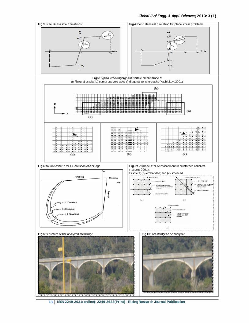
Fig 8: structure of the analyzed arc bridge
Fig 10: Arc Bridge to be analyzed
Global J. of Engg. & Appl. Sciences, 2013: 3 (1)
79 ISSN 2249-2631(online): 2249-2623(Print) - Rising Research Journal Publication
Fig 9: software development and simulation steps
Fig 11: selected subjected to forces and constraints Selected Face(s) Fixed Constraint with selected face(s)
Fig 12: von mises stress under first principal stress
Global J. of Engg. & Appl. Sciences, 2013: 3 (1)
80 ISSN 2249-2631(online): 2249-2623(Print) - Rising Research Journal Publication
Fig 13: Third principal stress
Fig 14: Displacement
Fig 15: Safety factor
Fig 16: stress
Fig 17: Strain
**************