finite element analysis of gas foil bearings
TRANSCRIPT
FINITE ELEMENT ANALYSIS OF
GAS FOIL BEARINGS
A PROJECT REPORT SUBMITTED IN
PARTIAL FULFILLMENT OF
Bachelor of Technology
In
Mechanical Engineering
By
Preetiranjan Pradhan
111ME0335
Under The Guidance of
Prof. Tarapada Roy
(Department Of Mechanical Engineering)
Department of Mechanical Engineering
National Institute of Technology
Rourkela-769008
2014-15
i
National Institute of Technology Rourkela
CERTIFICATE
This is to certify that the thesis entitled, “Finite Element Analysis of Gas Foil Bearings” submitted
by Mr. Preetiranjan Pradhan (111ME0335) in partial fulfillment of the requirements for the award
of Bachelor of Technology in Mechanical Engineering at the National Institute of Technology,
Rourkela is an authentic work carried out by them under my supervision and guidance. To the best
of my knowledge, the matter embodied in the thesis has not been submitted to any other
University/ Institute for the award of any Degree or Diploma.
Date: 01-05-2015 Prof. Tarapada Roy
Department of Mechanical Engineering
National Institute of Technology
Rourkela – 769008

ii
ACKNOWLEDGEMENT
I would like to express my deepest gratitude to the Project guide Prof. Tarapada Roy for his
innumerous contribution made towards the project and supporting for this project from the time of
its inception.
I am grateful to Prof. (Dr.) S. S. Mohapatra, Head of the Department, Mechanical Engineering for
providing me the necessary opportunities for the completion of my project. Our project supervisors
were instrumental in the process of bringing this project to its present form. Without their key
support, knowledge and experience, procurement of set-up, set-up of project equipment and analysis
work would not have been possible.
I wish to express my sincere thanks and gratitude to Mr. D Koteswar Rao and Mr. Ashirbad Swain
for helping me a lot during designing and development of my models and providing me the guidance,
motivation and constructive criticism throughout the course of the project.
Finally, I would like to thank my classmates, other colleagues and entire college environment for
their support and entrusting us with the project and finalizing this project within the limited period.
Preetiranjan Pradhan
Roll No. – 111ME0335
iii
ABSTRACT
Micro turbomachinery demands gas bearings to be light compact and should operate at varying
temperature conditions. Low heat generation friction and lack of lubricant circulation system makes
it compact reliable and eco-friendly. However low stiffness and damping coefficients, high cost and
lack of sufficient knowledge and predictive tools somewhat restricts GFBs use in mass produced
application. Current commercial and engineering application demands more and more aggressive
designs with high surface speed and unit loads as well as thinner fluid film. Again rotor-dynamics
analysis uses stiffness and damping coefficients to represent fluid film behavior or in other words
these coefficients play the key role in determining dynamic characteristics of a rotor shaft. Stiffness
coefficients depend mainly on two factors first the static deflection of foil due to shaft load and second
the hydrodynamic effect produced due to the fluid film. Here is an approach to calculate the stiffness
coefficient produced due to static deflection of GFBs due to static load using finite element analysis
and the stiffness coefficient has been calculated. Reynold’s equation is to be solved using FDM to
obtain pressure profile during hydrodynamic action of fluid film and using these pressure values in
the bearing model dynamic component of stiffness can be produced. Adding both components will
produce the overall stiffness coefficient of a gas foil bearing.
Key words: FEA, gas foil bearing, stiffness coefficients.
iv
LIST OF FIGURES AND TABLES
LIST OF FIGURES PAGE NO.
1. Typical commercial gas foil bearings for micro-turbomachinery 3
2. Figure 2: Commercially used bump foil and leaf foil bearings 3
3. Schematic view of extended bump strips and a typical bump foil bearing. 11
4. Bump foil structure 13
5. Top foil structure and Bearing sleeve. 14
6. Complete bump-type gas foil bearing. 14
7. Optimization of auto-generated mesh 15
8. Improvisation of element quality generated by automatic mesh 15
9. Applying boundary conditions and bearing load to GFB1… 17
10. Applying boundary conditions, thermal conditions and bearing… 18
11. Variation of total deformation. 19
12. Variation of equivalent stress. 19
13. Directional deformation (X-axis). 19
14. Directional deformation (Y-axis). 19
15. Bearing load (N) vs Deflection (mm) for GFB 1, (F1 vs X1) 21
16. Bearing load (N) vs Deflection (mm) for GFB 2, (F2 vs X2) 21
17. Bearing load (N) vs Deflection (mm) for GFB 3, (F3 vs X3) 22
18. Variation of total deformation at 10oC 23
19. Variation of equivalent stress at 10oC 23
20. Directional deformation (X-axis) at 10oC. 23
21. Directional deformation (Y-axis) at 10oC. 23
v
22. Stiffness (N/mm) vs Temperature (oC) for GFB 1 25
23. Stiffness (N/mm) vs Temperature (oC) for GFB 2 25
24. Stiffness (N/mm) vs Temperature (oC) for GFB 3 25
LIST OF TABLES PAGE NO
1. Parameters and dimensions of 3 gas foil bearings to be modelled and analyzed 12
2. Bearing loads for different GFBs for different pressure values. 16
3. Bearing load and directional deformation (X-axis) for a varying pressure range. 20
4. Temperature and directional deformation (along X-axis). 24

vi
CONTENTS
Chapter-1 INTRODUCTION 1-5
1.1 ROTOR DYNAMICS 1
1.2 BEARINGS 1
1.3 GAS FOIL BEARINGS 2-4
1.4 FINITE ELEMENT ANALYSIS 4-5
Chapter-2 LITERATURE SURVEY 6-10
2.1 LITERATURE REVIEW 6-9
2.2 MOTIVATION AND OBJECTIVE 10
Chapter-3 MODELLING AND METHOD 11-18
3.1 BUMP TYPE FOIL BEARING DESCRIPTION 11-12
3.2 DEVELOPMENT OF CAD MODELS 12-14
3.3 GENERATION OF MESH 15
3.4 METHOD FOR STIFFNESS CALCULATION 16-17
3.5 METHOD FOR TEMPERATURE DEPENDENT STIFFNESS CALCULATION 18
Chapter-4 RESULT AND DISCUSSION 19-25
4.1 CALCULATION OF STIFFNESS 19-22
4.2 VARIATION OF STIFFNESS WITH TEMPERATURE 23-25
CONCLUSION AND FUTURE SCOPES 26
REFERENCES 27-28
1
CHAPTER1: INTRODUCTION
1.1 ROTOR DYNAMICS
It’s the branch of engineering that focuses on vibrations of rotating shafts with objective being
predicting the vibration and keeping it below the acceptance level. The principal components are
a shaft or a rotor with a disk and a bearing. The shaft is the rotating component of the system and
many industrial applications have shafts designed in a long and thin geometry to provide optimum
space for components such as seals and impellers. The bearing supports the rotating shaft of the
system ad provide damping to stabilize the system and limit vibration to certain level.
1.2 BEARINGS
A bearing is a mechanical device that separates two opposing surfaces completely by a layer of
fluid lubricant. Plain journal bearing is used commercially in almost all devices that has a rotating
part. Compressors, pumps turbines, motors generators are few examples need to be mentioned.
Journal bearing is a structure where two cylinders rotate concentrically relative to each other. One
being the shaft, rotating at a particular angular speed, and other the bearing. The main objective is
to support the rotating structures and provide sufficient lubrication to avoid friction that causes
wear and tear to machine parts. The fluid film at high pressure provides the hydrodynamic film
lubrication and determines the load capacity of the bearing. Eccentricity is a bearing parameter
which is defined as the displacement between shaft and bearing center.
2
1.3 GAS FOIL BEARINGS
Foil bearings or gas foil bearings (GFB) comes under the category of air bearings. Here the shaft
is supported by a thin foil journal lining. Once the shaft moves at high speed the fluid film pushes
the shaft away to avoid contact. Shaft and foil are separated by high pressure fluid film (here
ambient air in most cases) generated by rotation which pulls air into the bearing via viscosity
effects. High speed of rotor with respect to the bearing creates this initial air gap which prevents
wear and tear. Unlike aero and hydrostatic bearings GFBs do not need external pressurized system
for working fluid hence these are self-staring bearings.
Micro turbomachinery demands gas bearings to be light compact and should operate at varying
temperature conditions. Gas bearings offer reduced heat generation low friction and don’t require
sealing and lubricant circulation system hence are compact, reliable and light weight also they
eliminate process fluid contamination [1] and are sustainable and ecofriendly, therefore GFBs with
high stiffness and damping coefficients and low cost will enable it for commercial usage; but high
cost and lack of sufficient knowledge and predictive tools have denied use of GFBs in mass
produced applications. Low load carrying capability and minute film thickness causes its
fabrication and installation costs money as well as time. Poor damping capacity due to low
viscosity of air is another disadvantage.
TYPES OF GAS FOIL BEARINGS:
Bearings in rotating machinery can be
a. Radial bearings supporting lateral loads including rotor weight
b. Thrust bearing carrying axial loads
3
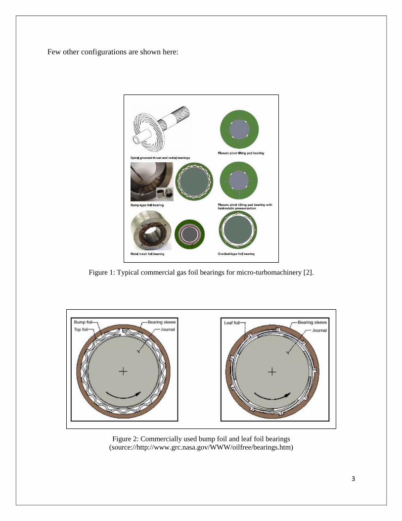
Few other configurations are shown here:
Figure 1: Typical commercial gas foil bearings for micro-turbomachinery [2].
Figure 2: Commercially used bump foil and leaf foil bearings
(source://http://www.grc.nasa.gov/WWW/oilfree/bearings.htm)

4
In bump-type GFBs the top foil is supported by series of compliant bumps and deforms elastically
under hydrodynamic fluid film pressure. The bearing stiffness is a combined result from the bump
deflection and also by the hydrodynamic film generated during the shaft rotation. Coulomb type
damping arises between the bumps and the top foil or between the bumps and bearing wall. GFBs
also allow larger misalignments of shafts as the foils comply and deflect under misalignment. All
sorts of misalignments caused due to tolerance build-ups, thermal expansion and centrifugal shaft
growth are absorbed at the cost of expansion of the top foil. GFBs generally uses ambient air but
lubricants like LOX and inert gases can also be used for specific application
Currently they find their applications in air-cycle units in aircrafts, cryogenic turbo expanders for
gas separation plants, high precision instruments, power units of aerospace as well as ground
vehicles, gas turbines of automobiles, compressors and MTM.
1.4 FINITE ELEMENT ANALYSIS
FEA is a numerical technique developed to solve complex problems dealing with varying shape,
boundary conditions and loads. The basic idea is to replace the complicated problem by a simpler
one hence the solutions obtained are approximate. The existing tools might not be sufficient to
obtain the exact solution or even an approximate solution. This leads us to FEA to solve such
problems, however more computational effort can be provided to refine the approximate solution.
This originated as a method of stress analysis in designing aircrafts but today we can see it
application a varying fields such as solid mechanics, fluid flow heat transfer, design of civil
structures, air crafts, space crafts, electric motors and heat engines. Finite element analysis is very
much versatile and can handle both static and dynamic problems.
5
In engineering we have to find few parameters or field variables, once these are obtained behavior
of entire structure can be calculated. These field variables may be displacements in solid mechanics
and velocities in fluid. In a continuum these are infinite. FEA reduces these field variables to a
finite number by dividing solution region into smaller elements and field variables are assumed as
approximate functions within each elements. These functions are defined in terms of the unknowns
or field variables of specified points called nodal points or nodes. Thus in FEA the unknowns are
the field variables of nodal points, once they are obtained the field variable at any point can be
calculated using interpolation functions.
ADVANTAGES OF FEA:
i. Solutions for all sorts of problem can be obtained although they are approximate.
ii. It can handle materials with anisotropic properties without any difficulty.
iii. Solutions of problems involving critical geometry and critical boundary conditions can be
solved easily.
iv. If structure comprises more than one material then FEA is more reliable than any other
method.
v. Problems with material and geometric non-linearity can be handled with ease by FEA.
6
CHAPTER 2: LITERATURE SURVEY
2.1 LITERATURE REVIEW
Carpino and peng [3] calculated stiffness and damping coefficients of a foil bearing supported
elastically. Ambient gas is used as fluid film and properties are obtained by Reynold’s equations.
Structural model is designed and both the equations fluid and structural are coupled and
perturbation method is deployed to obtain dynamic equations. FDM has been used to calculate all
coefficients and it is found that the elastic foundation reduces these coefficients and these
coefficients are very much important in determining rotor shaft stability and calculations of rotor
dynamics. As this methods calculates all above coefficients in general manner from perturbation
equations numerical errors are less and accuracy is more.
Heshmat et al. [4] used a spring supported compliance bearing to evaluate performance of a GFB.
Analysis of effect of various structural and geometric variables on bearing performance and
behavior was done. Solution of relevant differential equations includes values of spring
coefficients due to both structural and hydrodynamic stiffness. Desirable design features are
discussed. A comparative study of stability of GFBs shows that bearings can be designed to a
desired stiffness to fulfill demands of its rotor dynamics system.
Heshmat et al. [5] later observed that load performance of GFB is related to bearing compliance
and hydrodynamics of wedge surface, where compliance comprises elastically foundation and top
foil. They combined finite difference and finite element method to investigate a class of gas foil
thrust bearing analytically. Hydrodynamic equation is solved and solution is coupled with
structural resiliency. And FD and FE method are used to solve above mentioned problem
respectively. Elasticity effects of this combined system is addressed by the influence coefficients

7
and convergence was obtained. Application of FDM and FEA coherently proved to be a great
methodology to handle analysis of GFBs.
Czolczyński [6] for analyzing motion of machines like GFBs believed it is convenient to represent
dynamic property by means of stiffness and dynamic coefficients. He represented GFB by a
mathematical model based on Reynold’s equations and other few equations to describe gas flow
in feeding systems. The coefficients obtained are functions of bearing parameters, external load,
angular velocity of shaft and its frequency of vibration they also determine stability resonance
vibration and amplitude of unbalanced vibration. He also pointed out that during solving the
equations the larger distance between grid points (for calculating coefficients) lead to significant
between real values and values of the curve fitted polynomial.
Lee et al. [7] investigated dynamic performance of GFBs at high temperatures experimentally. A
GFB was mounted on a rotating shaft, which was hollow, a cartridge heater heated the shaft from
inside and the shaft was excited by two electromagnetic shakers orthogonally to determine the
frequency dependent stiffness and damping coefficient in a dynamic performance test rig. A set of
temperatures and frequency were taken for conducting the experiment whereas load and rpm kept
constant. They identified that cross coupled coefficients of a GFB are smaller than direct
coefficients.
Park et al. [8] investigated rotor-dynamics of a micro power system supported by GFBs. FEM was
used to perform stability analysis with predicted dynamic coefficients of the foil bearing. A test
rig was prepared to simulate operating characteristics for e.g. Speed up to 300k rpm was considered
and results for unbalance response were compared. They finally showed stable performance can
be achieved using a GFB.

8
Miqskowski [9] presented selected numerical models being used for modelling gas foil bearings
all around the universe. Difficulties arising due to complex structure of GFB are addressed. For
analyzing a GFB the structural base hydrodynamic effect and their interaction is to be considered.
Current modelling are time consuming and costly hence a reliable method is required to contribute
significantly to bearing design.
Jamir et al. [10] noticed the poor load carrying tendency of gas foil bearings and provided a
numerical method to obtain the performance of GFBs. FDM is employed to get non-dimensional
form and discretize Reynold’s equation and pressure profile is generated using numerical methods
(here Newton-Raphson technique). Static performance test are carried out and compared with
results presented earlier. Their study pointed out the effect of low load carrying capacity due to
thinner fluid film and need of detail foil structure for more finite element analysis.
Andres and Wilde [11] advanced for a novel finite element method for analyzing gas foil bearings.
To prevent non symmetrical weigh function they introduced a higher order weigh function that
naturally incorporates flow character. This FE formulation model proves to be accurate fast,
reliable and efficient however neglects impact due to high speed operations.
Andres and Kim [12] noticed that performance of GFB depends largely on its top foil and bump
foil which is the elastic structure of a foil bearing. Age old methods include these foils as an
equivalent stiffness uniformly present around bearing circumference. More complex FE modelling
was done to estimate the deformation of the foils rather than assuming it like an elastic foundation.
And the observation predicted that the coefficients against excitation frequency indicated that FE
modelled coefficients are less than the coefficients obtained from simple elastic foundation model.

9
Muruganandam et al. [13] designed gas foil bearing suitable for a high speed micro gas turbine.
Mathematical modelling is carried out to apply symmetrical loading to turbine blades and to
investigate dynamic motion numerical simulation has been deployed. The rotor is supported by a
set of GFBs which are having a cylindrical bush and of radial configuration. For the shaft system
Reynold’s equation is solved to get air pressure profile in the fluid film. Load capacity is derived
by integrating pressure profile over the bearing surface. Displacement velocity and dynamic
components are used to calculate damping and stiffness coefficient of the gas foil bearing.
San Andres L [14] investigated Hydrodynamic Fluid Film Bearings and Their Effect on the
Stability of Pivoting Machinery with the static and dynamic execution attributes of short
length cylindrical journal bearing, with application to the dynamic constrained execution of
a unbending rotor upheld on plain orientation. In a radial bearing, the Sommerfield number
characterizes a relationship between the static force and the bearing eccentricity inside the bearing.
These liquid film direction additionally present gooey damping that helps in diminishing
the adequacy of vibrations in working hardware. Reynolds mathematical statement for bearing
was inferred which portrays the sum of hydrodynamic weight inside the bearing.
Schiffmann et al. [15] investigated Foil Bearing Design Guidelines for Improved Stability. A lower
order foil bearing model, coupled with an inflexible body, linear rotor element model, was utilized
to research the basic rotor dynamic instruments and the onset speed of insecurity of a foil
bearing-upheld by the rotor.. A sensitivity analysis exhibits that auxiliary damping does not
altogether change the onset of sub-synchronous whirl. It is demonstrated, on the other hand, that
the introduction of the pivotal food line of the top foil can firmly impact the bearing load limit and
rotor dynamic execution.
10
2.2 MOTIVATION AND OBJECTIVE
Based on the literature review it is quite clear that many works have been carried out and completed
in analysis of gas foil bearings. For the fluid film thickness (in this case air) the help of Reynold’s
equation is used and subsequently using finite difference method or similar numerical methods the
pressure profile is calculated. And using this pressure values dynamic coefficients of a foil bearings
like stiffness and damping coefficients are calculated. In most of the models developed as of now
top foil and bump foil is assumed as an elastic foundation structure and its static stiffness is often
ignored.
Here an attempt is made to design CAD model of a bearing and analyze it to obtain its static
deflection under the influence of a normal load. After obtaining deflections at multiple loads one
can easily obtain static stiffness.
MAIN OBJECTIVES ARE:
1. Develop CAD models of a bump-type gas foil bearing.
2. Finite element analysis of GFBs.
3. Calculate stiffness values for different GFBs
11
CHAPTER 3: MODELLING AND METHODS
3.1 BUMP-TYPE FOIL BEARING DESCRIPTION
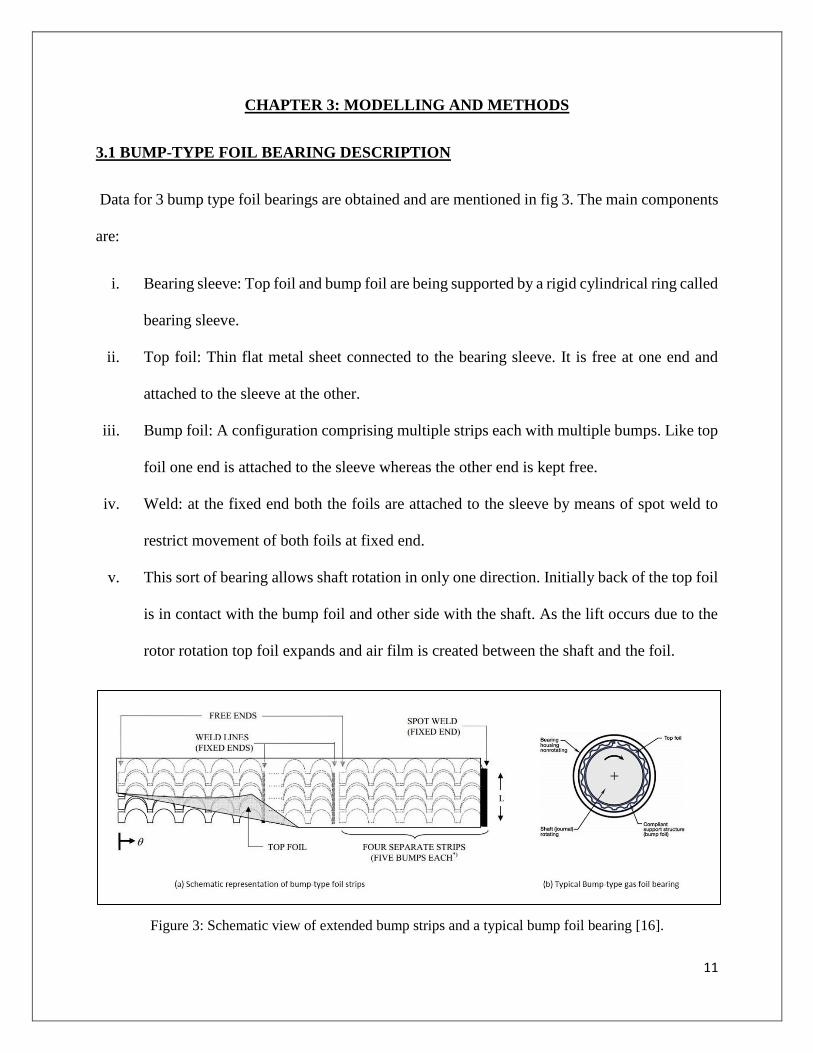
Data for 3 bump type foil bearings are obtained and are mentioned in fig 3. The main components
are:
i. Bearing sleeve: Top foil and bump foil are being supported by a rigid cylindrical ring called
bearing sleeve.
ii. Top foil: Thin flat metal sheet connected to the bearing sleeve. It is free at one end and
attached to the sleeve at the other.
iii. Bump foil: A configuration comprising multiple strips each with multiple bumps. Like top
foil one end is attached to the sleeve whereas the other end is kept free.
iv. Weld: at the fixed end both the foils are attached to the sleeve by means of spot weld to
restrict movement of both foils at fixed end.
v. This sort of bearing allows shaft rotation in only one direction. Initially back of the top foil
is in contact with the bump foil and other side with the shaft. As the lift occurs due to the
rotor rotation top foil expands and air film is created between the shaft and the foil.
Figure 3: Schematic view of extended bump strips and a typical bump foil bearing [16].
12
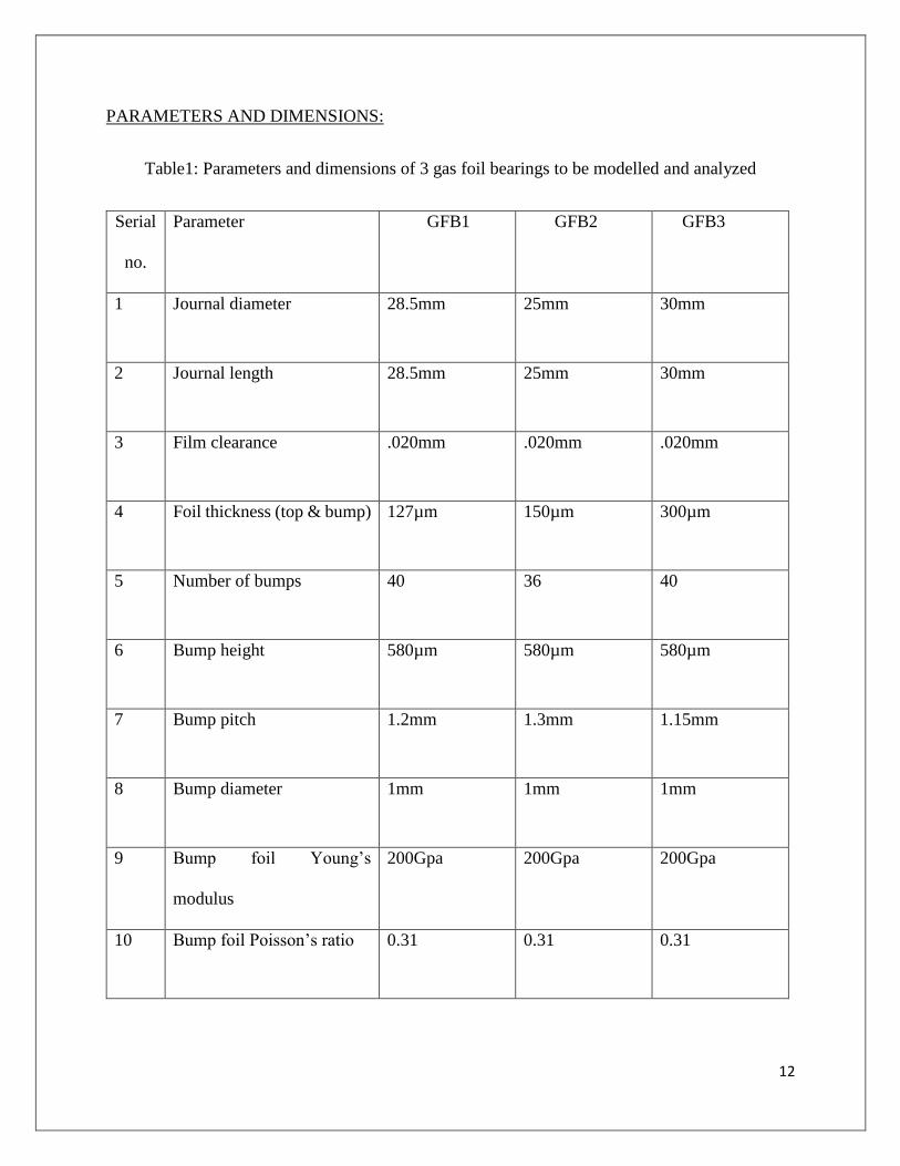
PARAMETERS AND DIMENSIONS:
Table1: Parameters and dimensions of 3 gas foil bearings to be modelled and analyzed
Serial
no.
Parameter GFB1 GFB2 GFB3
1 Journal diameter 28.5mm 25mm 30mm
2 Journal length 28.5mm 25mm 30mm
3 Film clearance .020mm .020mm .020mm
4 Foil thickness (top & bump) 127µm 150µm 300µm
5 Number of bumps 40 36 40
6 Bump height 580µm 580µm 580µm
7 Bump pitch 1.2mm 1.3mm 1.15mm
8 Bump diameter 1mm 1mm 1mm
9 Bump foil Young’s
modulus
200Gpa 200Gpa 200Gpa
10 Bump foil Poisson’s ratio 0.31 0.31 0.31
13
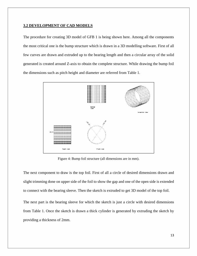
3.2 DEVELOPMENT OF CAD MODELS
The procedure for creating 3D model of GFB 1 is being shown here. Among all the components
the most critical one is the bump structure which is drawn in a 3D modelling software. First of all
few curves are drawn and extruded up to the bearing length and then a circular array of the solid
generated is created around Z-axis to obtain the complete structure. While drawing the bump foil
the dimensions such as pitch height and diameter are referred from Table 1.
Figure 4: Bump foil structure (all dimensions are in mm).
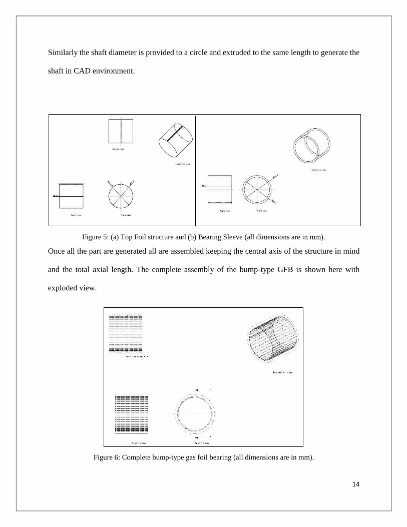
The next component to draw is the top foil. First of all a circle of desired dimensions drawn and
slight trimming done on upper side of the foil to show the gap and one of the open side is extended
to connect with the bearing sleeve. Then the sketch is extruded to get 3D model of the top foil.
The next part is the bearing sleeve for which the sketch is just a circle with desired dimensions
from Table 1. Once the sketch is drawn a thick cylinder is generated by extruding the sketch by
providing a thickness of 2mm.
14
Similarly the shaft diameter is provided to a circle and extruded to the same length to generate the
shaft in CAD environment.
Figure 5: (a) Top Foil structure and (b) Bearing Sleeve (all dimensions are in mm).
Once all the part are generated all are assembled keeping the central axis of the structure in mind
and the total axial length. The complete assembly of the bump-type GFB is shown here with
exploded view.
Figure 6: Complete bump-type gas foil bearing (all dimensions are in mm).

15
3.3 GENERATION OF MESH
Generating mesh is the most important and critical work in engineering simulation in Ansys
software. Large no of cells may take longer time to produce solutions without increasing accuracy
whereas very few number of cells might produce inaccurate results. Ansys meshing technology
provides automated way of generating adequate no of mesh to provide optimum solution. Once
the CAD model of the GFB is completed it is imported to the Ansys environment for further
simulation. To obtain adequate no of cells automatic mesh is generated. Further relevance center
is changed and tetrahedron elements percentage increased to a significant number in order to
achieve smooth surface and better mesh quality. The changes in mesh quality is shown below.
Figure 7: Optimization of auto-generated mesh.
Figure 8: Improvisation of element quality generated by automatic mesh.

16
3.4 METHOD FOR STIFFNESS CALCULATION
After generation mesh various supports and loads are to be given to these GFBs for calculations
of respective deflections.
3.4.1 CALCULATION OF APPLIED LOAD:
The working pressure of a bearing is estimated which lies around 0.1N/mm2 to 1N/mm2. Now to
estimate the bearing load the following formula is used:
F1=Pa×π×L×D/2.
Where
F1= Bearing load to be applied on top foil in N.
Pa= Working pressure of a bearing in N/mm2
L= Length of the journal in m.
D= Journal Diameter in m.
The pressure is taken in 10 steps (0.1, 0.2…1.0) and subsequent load values for forces were
calculated for all three bearings.
Applied loads:
Table 2: Bearing loads for different GFBs for different pressure values.
Pressure 0.1 0.2 0.3 0.4 0.5 0.6 0.7 0.8 0.9 1.0
F1(GFB1) 128 255 383 510 638 766 893 1020 1150 1280
F2(GFB2) 98.2 196.4 294.5 392.7 490.9 589.1 687.2 785.4 883.6 981.75
F3(GFB3) 141 283 424 565 707 848 990 1130 1270 1410
17
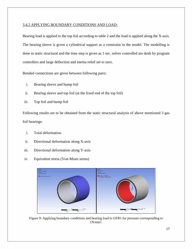
3.4.2 APPLYING BOUNDARY CONDITIONS AND LOAD:
Bearing load is applied to the top foil according to table 2 and the load is applied along the X-axis.
The bearing sleeve is given a cylindrical support as a constraint in the model. The modelling is
done in static structural and the time step is given as 1 sec. solver controlled are dealt by program
controllers and large deflection and inertia relief set to zero.
Bonded connections are given between following pairs:
i. Bearing sleeve and bump foil
ii. Bearing sleeve and top foil (at the fixed end of the top foil)
iii. Top foil and bump foil
Following results are to be obtained from the static structural analysis of above mentioned 3 gas
foil bearings:
i. Total deformation
ii. Directional deformation along X-axis
iii. Directional deformation along Y-axis
iv. Equivalent stress (Von-Mises stress)
Figure 9: Applying boundary conditions and bearing load to GFB1 for pressure corresponding to
1N/mm2.
18
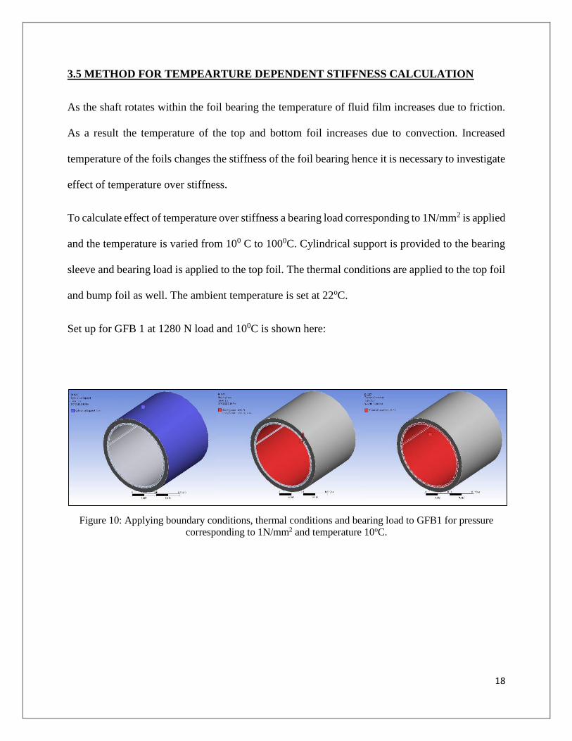
3.5 METHOD FOR TEMPEARTURE DEPENDENT STIFFNESS CALCULATION
As the shaft rotates within the foil bearing the temperature of fluid film increases due to friction.
As a result the temperature of the top and bottom foil increases due to convection. Increased
temperature of the foils changes the stiffness of the foil bearing hence it is necessary to investigate
effect of temperature over stiffness.
To calculate effect of temperature over stiffness a bearing load corresponding to 1N/mm2 is applied
and the temperature is varied from 100 C to 1000C. Cylindrical support is provided to the bearing
sleeve and bearing load is applied to the top foil. The thermal conditions are applied to the top foil
and bump foil as well. The ambient temperature is set at 22oC.
Set up for GFB 1 at 1280 N load and 100C is shown here:
Figure 10: Applying boundary conditions, thermal conditions and bearing load to GFB1 for pressure
corresponding to 1N/mm2 and temperature 10oC.
19
CHAPTER 4: RESULT AND DISCUSSION
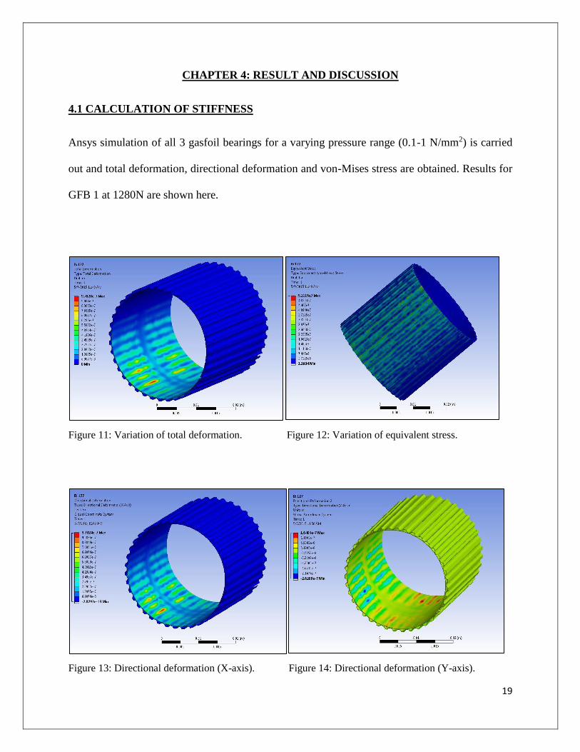
4.1 CALCULATION OF STIFFNESS
Ansys simulation of all 3 gasfoil bearings for a varying pressure range (0.1-1 N/mm2) is carried
out and total deformation, directional deformation and von-Mises stress are obtained. Results for
GFB 1 at 1280N are shown here.
Figure 11: Variation of total deformation. Figure 12: Variation of equivalent stress.
Figure 13: Directional deformation (X-axis). Figure 14: Directional deformation (Y-axis).
20
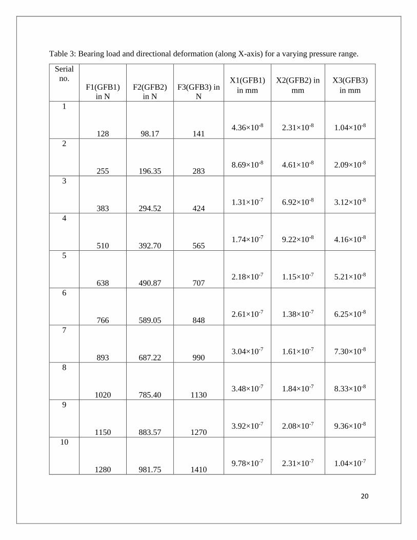
Table 3: Bearing load and directional deformation (along X-axis) for a varying pressure range.
Serial
no. F1(GFB1)
in N
F2(GFB2)
in N
F3(GFB3) in
N
X1(GFB1)
in mm
X2(GFB2) in
mm
X3(GFB3)
in mm
1
128 98.17 141 4.36×10⁻⁸ 2.31×10⁻⁸ 1.04×10⁻⁸
2
255 196.35 283 8.69×10⁻⁸ 4.61×10⁻⁸ 2.09×10⁻⁸
3
383 294.52 424 1.31×10⁻⁷ 6.92×10⁻⁸ 3.12×10⁻⁸
4
510 392.70 565 1.74×10⁻⁷ 9.22×10⁻⁸ 4.16×10⁻⁸
5
638 490.87 707 2.18×10⁻⁷ 1.15×10⁻⁷ 5.21×10⁻⁸
6
766 589.05 848 2.61×10⁻⁷ 1.38×10⁻⁷ 6.25×10⁻⁸
7
893 687.22 990 3.04×10⁻⁷ 1.61×10⁻⁷ 7.30×10⁻⁸
8
1020 785.40 1130 3.48×10⁻⁷ 1.84×10⁻⁷ 8.33×10⁻⁸
9
1150 883.57 1270 3.92×10⁻⁷ 2.08×10⁻⁷ 9.36×10⁻⁸
10
1280 981.75 1410 9.78×10⁻⁷ 2.31×10⁻⁷ 1.04×10⁻⁷
21
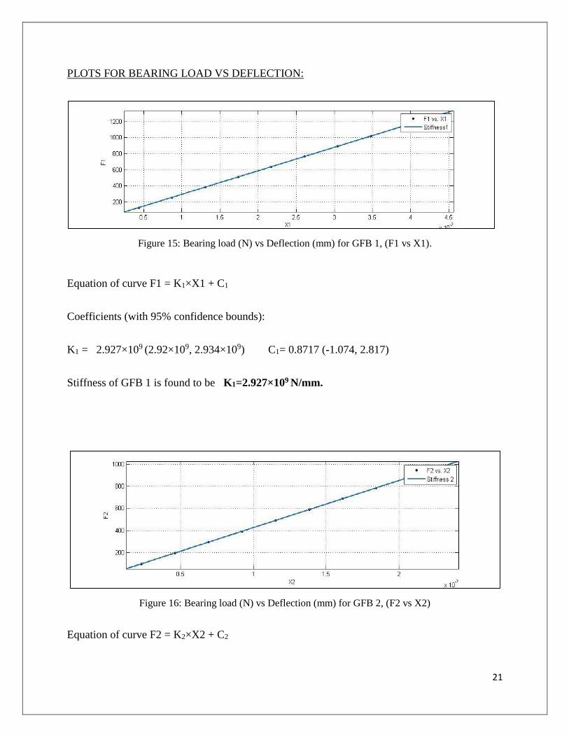
PLOTS FOR BEARING LOAD VS DEFLECTION:
Figure 15: Bearing load (N) vs Deflection (mm) for GFB 1, (F1 vs X1).
Equation of curve F1 = K1×X1 + C1
Coefficients (with 95% confidence bounds):
K1 = 2.927×10⁹ (2.92×10⁹, 2.934×10⁹) C1= 0.8717 (-1.074, 2.817)
Stiffness of GFB 1 is found to be K1=2.927×10⁹ N/mm.
Figure 16: Bearing load (N) vs Deflection (mm) for GFB 2, (F2 vs X2)
Equation of curve F2 = K2×X2 + C2
22
Coefficients (with 95% confidence bounds):
K2= 4.258×10⁹ (4.257×10⁹, 4.258×10⁹) C2= 0.003786 (-0.003053, 0.01063)
Stiffness of GFB 2 is found to be K2=4.258×10⁹ N/mm.
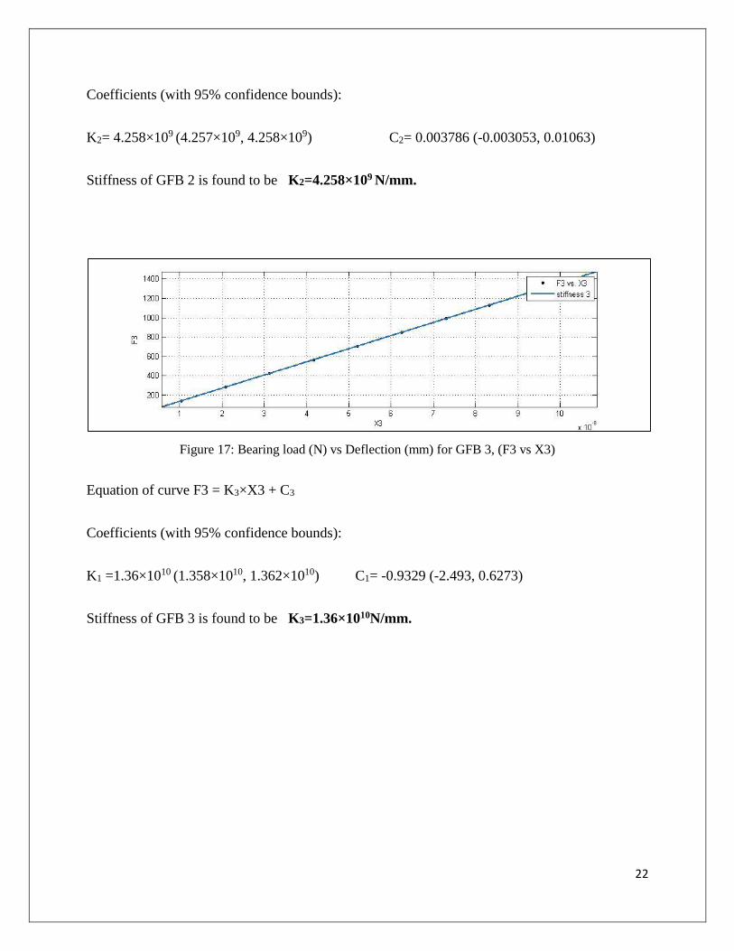
Figure 17: Bearing load (N) vs Deflection (mm) for GFB 3, (F3 vs X3)
Equation of curve F3 = K3×X3 + C3
Coefficients (with 95% confidence bounds):
K1 =1.36×10¹⁰ (1.358×10¹⁰, 1.362×10¹⁰) C1= -0.9329 (-2.493, 0.6273)
Stiffness of GFB 3 is found to be K3=1.36×10¹⁰N/mm.

23
4.2 VARIATION OF STIFFNESS WITH TEMPERATURE
Ansys simulation of all 3 gasfoil bearings for a fixed pressure 1N/mm2 is carried out and total
deformation, directional deformation and von-Mises stress are obtained. Results for GFB 1 at
1280N are shown here.
Figure 18: Variation of total deformation at 10oC. Figure 19: Variation of equivalent stress at 10oC.
Figure 20: Directional deformation (X-axis) at 10oC. Figure 21: Directional deformation (Y-axis) at 10oC.
24
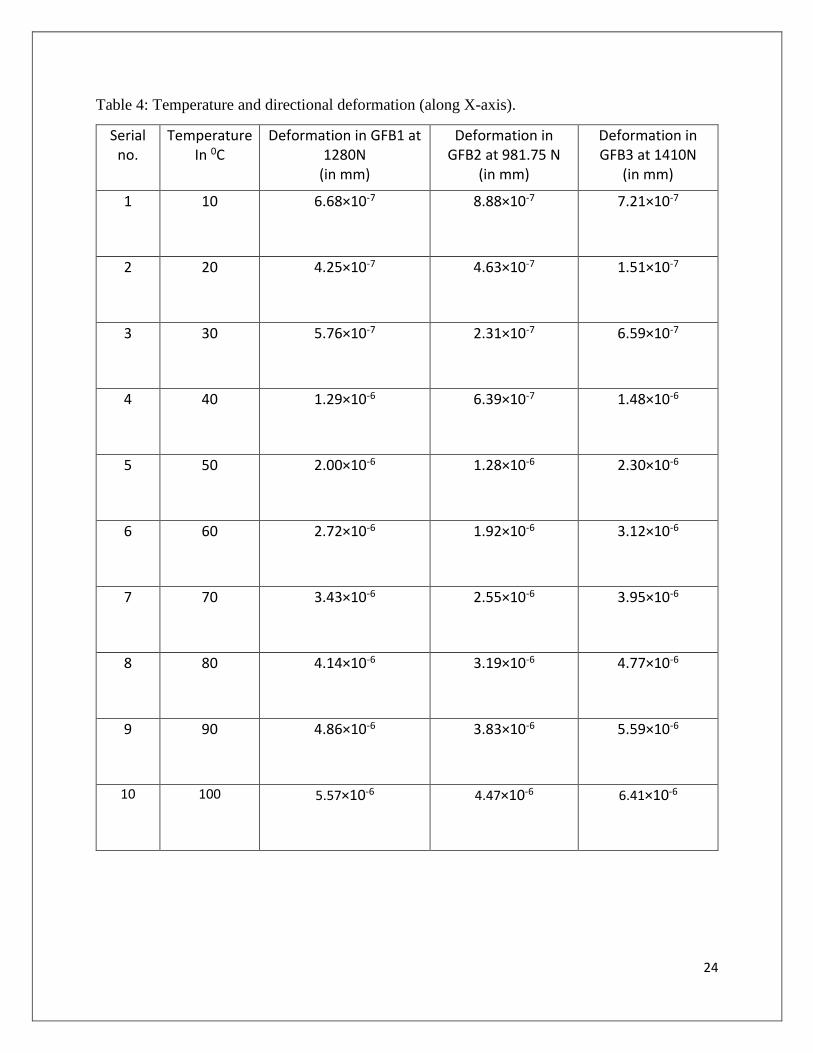
Table 4: Temperature and directional deformation (along X-axis).
Serial no.
Temperature In 0C
Deformation in GFB1 at 1280N
(in mm)
Deformation in GFB2 at 981.75 N
(in mm)
Deformation in GFB3 at 1410N
(in mm)
1 10 6.68×10⁻⁷ 8.88×10⁻⁷ 7.21×10⁻⁷
2 20 4.25×10⁻⁷ 4.63×10⁻⁷ 1.51×10⁻⁷
3 30 5.76×10⁻⁷ 2.31×10⁻⁷ 6.59×10⁻⁷
4 40 1.29×10⁻⁶ 6.39×10⁻⁷ 1.48×10⁻⁶
5 50 2.00×10⁻⁶ 1.28×10⁻⁶ 2.30×10⁻⁶
6 60 2.72×10⁻⁶ 1.92×10⁻⁶ 3.12×10⁻⁶
7 70 3.43×10⁻⁶ 2.55×10⁻⁶ 3.95×10⁻⁶
8 80 4.14×10⁻⁶ 3.19×10⁻⁶ 4.77×10⁻⁶
9 90 4.86×10⁻⁶ 3.83×10⁻⁶ 5.59×10⁻⁶
10 100 5.57×10⁻⁶ 4.47×10⁻⁶ 6.41×10⁻⁶

25
PLOTS FOR TEMPERATURE VS STIFFNESS:
Fig 22: Stiffness (N/mm) vs Temperature (oC) for GFB 1.
Fig 23: Stiffness (N/mm) vs Temperature (oC) for GFB 2.
Fig 24: Stiffness (N/mm) vs Temperature (oC) for GFB 3.
0.00E+00
5.00E+08
1.00E+09
1.50E+09
2.00E+09
2.50E+09
3.00E+09
3.50E+09
0 20 40 60 80 100 120
Stif
fnes
s K
1 in
N/m
m
Temperature in oC
Chart Title
0.00E+00
5.00E+08
1.00E+09
1.50E+09
2.00E+09
2.50E+09
3.00E+09
3.50E+09
4.00E+09
4.50E+09
0 20 40 60 80 100 120
Stif
fnes
s K
2 in
N/m
m
Temperature in oC
Chart Title
0.00E+00
2.00E+09
4.00E+09
6.00E+09
8.00E+09
1.00E+10
0 20 40 60 80 100 120Stif
fnes
s K
3 in
N/m
m
Temperature in oC
Chart Title
26
CONCLUSION
Bearing load is applied to 3 different models of gas foil bearings. Deflections for different load
values obtained using finite element analysis. Graph is plotted between load and deflection and a
straight line is obtained, the slope of each curve represents stiffness of each bearing.
Graph between stiffness and temperature is plotted and the variation is obtained. It is observed that
the stiffness is maximum as the temperature of the bearing coincides with the ambient temperature
and stiffness reduces as the temperature difference between the bearing and working environment
increases.
FUTURE SCOPES:
In this report stiffness due to static load and its variation according to working temperature is
obtained. Based on the results obtained following works can be done in future:
i. Pressure variation due to hydrodynamic effect of fluid film can be calculated and
incorporated to the designed model to obtain dynamic coefficient and both these stiffness
values will provide the overall stiffness of the gas foil bearing.
ii. Similarly damping coefficients can be calculated for any air foil bearing.
iii. Once both the dynamic coefficients (stiffness and damping) are obtained those values
can be fed to rotor-dynamics simulation for vibration analysis and determination of
critical speed.
27
REFERENCES
[1].San Andrés L, Hybrid Flexure Pivot –Tilting Pad Gas Bearings: Analysis and Experimental
Validation, Magnetic Storage Tribology Manufacturing/Metal working Tribology Nano-tribology
Engineered Surfaces Bio-tribology Emerging Technologies Special Symposia on Contact
Mechanics Special Symposium on Nano tribology, 2006.
[2]. San Andrés L, Notes 15, Gas Film Lubrication, Texas A&M University, 2010.
[3]. Carpino M and Peng J, Calculation of stiffness and damping coefficients for elastically
supported gas foil bearings. ASME/STLE Tribology Conference, 92-Trib-24 ASME, 1993.
[4]. Heshmat H, Walowitt J, Pinkus O, Analysis of gas lubricated foil journal bearing,
ASME/ASLE Joint Lubrication conference, ASME Journal of Lubrication Technology, 82-Lub-
40,1983.
[5]. Heshmat C, Xu D, Heshmat H, Analysis of Gas Lubricated Foil Thrust Bearings Using
Coupled Finite Element and Finite Difference Methods. ASME/ STLE Tribology Conference,
Paper No. 99-Trib-34, 1999.
[6]. Czotczyfiski K, How to obtain stiffness and damping coefficients of gas bearings, Division
of Dynamics, Technical University of Stefonowslaego 1/15.90.924, Poland, 1996.
[7]. Lee et al., Identification of the dynamic performance of a gas foil journal bearing operating at
high temperatures, Journal of Mechanical Science and Technology 28 (1) (2014) .
[8]. Park D, Lee Y, Kim C, Ryu K, Rotor-dynamic characteristics of a micro turbo generator
supported by air foil bearings. Journal of Micromechanics and Micro engineering, J. Micromech.
Microeng. 17(2007) 297-303.
28
[9]. Miąskowski W, Pietkiewicz P, Żywica G, Modelling Foil Bearings, Techn. Sc., No 12 Y,
2009.
[10]. Karuna K, Kakoty S, Jamir T, Gas Foil Bearing Analysis and the Effect of Bump Foil
Thickness on Its Performance Characteristics Using a Non-Linear Matrix Equation Solver,
International Journal of Recent advances in Mechanical Engineering (IJMECH) 3(3), August
2014.
[11]. San Andre´s L and Wilde D, Finite element analysis of gas bearings for oil-free
turbomachinery, Publisher: Taylor & Francis, London, UK, 2012.
[12]. San Andre´s L and Kim T, Analysis of gas foil bearings integrating FE top foil models,
Tribology International 42 (2009) 111– 120.
[13]. Muruganandam et al., Design of Air Bearing for High Speed Micro Gas Turbine.
[14]. San Andres L, Hydrodynamic Fluid Film Bearings and Their Effect on the Stability
of Rotating Machinery, Turbomachinery Laboratory, Texas A&M University,2006.
[15].Schiffmann L, and Spakovszky S, Foil Bearing Design Guidelines for Improved
Stability, Journal of Tribology, January 2013, Vol. 135.
[16]. Rubio D, San Andres L, Bump-Type Foil Bearing Structural Stiffness: Experiments and
Predictions, Research Progress Report to the Turbomachinery Research Consortium, TRC-B&C-
5-03,2003.