finite element analysis of crane secondary truss Конечно...
TRANSCRIPT

Инженерно-строительный журнал, № 1, 2018
Туснина О.А. Конечно-элементное моделирование и расчёт подкраново-подстропильной фермы //
Инженерно-строительный журнал. 2018. № 1(77). С. 68–89.
doi: 10.18720/MCE.77.7
Finite element analysis of crane secondary truss
Конечно-элементное моделирование и расчёт подкраново-подстропильной фермы
O.A. Tusnina, National Research Moscow State Civil Engineering University, Moscow, Russia
Канд. техн. наук, доцент О.А. Туснина, Национальный исследовательский Московский государственный строительный университет, г. Москва, Россия
Key words: crane secondary truss; thin-walled closed profile; restrained torsion; finite element analysis
Ключевые слова: подкраново-подстропильная ферма; тонкостенный замкнутый профиль; стесненное кручение; конечно-элементный расчет
Abstract. Finite element analysis of the crane secondary truss of top-blown oxygen vessel plant with the span of 36m is considered in the paper. Analysis of crane secondary truss is quiet difficult because of necessity of taking into account actual stiffness of its joints and also because of the fact that lower belt of truss made of thin-walled closed profile is experiencing restrained torsion because of eccentrically crane load acting. For these reasons modeling of crane secondary truss with the use of beam finite elements not allows to obtain correct results. That is why the shell finite elements should be used to model crane secondary truss. The required finite element mesh is determined in the paper. Participation of the truss into work of entire building skeleton is analyzed and the design scheme of the framework that allowed to obtain reliable results is selected.
Аннотация. В статье рассмотрен конечно-элементный расчет подкраново-подстропильной фермы (ППФ) конвертерного цеха пролетом 36 м. Расчет подкраново-подстропильной фермы достаточно сложен в связи с необходимостью учета фактической жесткости узлов фермы, а также в связи с тем, что нижний пояс фермы, выполненный из тонкостенного замкнутого профиля из-за эксцентричного приложения нагрузки от крана, кроме изгиба испытывает стесненное кручение. По этим причинам, применение стержневых конечных элементов для расчета ППФ не позволяет получить точные результаты и расчет фермы необходимо выполнять с применение конечных элементов оболочки. В статье определена требуемая сетка разбиения стержней фермы на конечные элементы. Проанализировано включение фермы в пространственную работу всего сооружения и выделена расчетная схема каркаса, в составе которой необходимо выполнять расчет фермы для получения достоверных результатов.
1. Introduction The crane secondary trusses are applied in industrial buildings. In this case crane secondary truss
is not taking load only from crane but it works also like secondary truss and takes load from roof [1]. Such structures are widespread in industrial buildings of metallurgical plants. The spans of crane secondary trusses can be up to 48 m and crane lifting capacity can be 400 tons and more. Crane operation modes on metallurgical plants are 7K, 8K. To execute sufficiently accurate calculation of such responsible structures is complicated because of the next reasons:
- elements of truss are made of large welded I-beams and closed box profiles which have great stiffness as in the plane of truss so from the plane;
- the actual stiffness of joints of the truss should be taken into account [2], besides there are transverse edges and sheets of local reinforcement of profiles in the joints that should be taken into account when analyzing stress strain-state of the truss;
- the large local concentrated crane forces applied with eccentricity to the lower belt of truss made of thin-walled welded box cause its restrained torsion;
- the complexity of the development of the finite element model of the truss made with the use of beam or shell or solid elements;
68

Magazine of Civil Engineering, No. 1, 2018
Tusnina O.A. Finite element analysis of crane secondary truss. Magazine of Civil Engineering. 2018. No. 1.
Pp. 68–89. doi: 10.18720/MCE.77.7.
- the problem of analysis crane secondary truss because of the complexity of the precise determination of the impacts on it taking into account the work of the truss as the part of spatial framework of the building;
- the analysis of large design schemes of the building with the trusses included in the scheme.
The greatest problem is the analysis of lower belt of the truss made of thin-walled box profile which experiences torsion. The stress-strain state of a thin-walled beam when its work in torsion rather complicated, additional normal stresses and deformations occurs in it. [3]. The classical theory of calculation on torsion of thin-walled beams with closed profile was developed by A.A. Umansky [4]. The investigations of stress-strain state of thin-walled closed profile beams and different method of analysis are proposed in the papers [5–10]. In the articles [11, 12] the influence of shear on the behavior of closed profile in torsion is analyzed. The papers [13, 14] are devoted to the problems of buckling of such profiles. Modeling of support contour of the membrane made of thin-walled closed profile that experiences considerable torsion with the use of beam finite elements gives incorrect results, and it is necessary to use shell finite elements for analysis [15].
It is advisable to carry out analysis of crane secondary truss with the use of finite element method implemented in many modern software systems.
The model of crane secondary truss made with the use of beam elements are most simple. Such a model can be easy built in the spatial design scheme of the framework of building. Impacts on the truss on the side of the structures adjacent to it are determined by the calculation of spatial construction. However, the beam model does not fully reflect the features of the design as it does not allow to determine the stress-strain state of the joints taking into account the ribs and reinforcement sheets in them.
The use of beam finite elements for modeling of the truss does not allow obtaining reliable results for a number of reasons:
- big height of the lower belt (up to 3 m) made of thin-walled closed profile, its complexity stress-strain state and its torsion;
- necessity of taking into account of actual stiffness of truss joints which can not be done with the use of beam elements.
In addition, the fatigue cracks and other defects are arise in the elements of truss because of the heavy operation mode of the cranes, their heavy load capacity and dynamic impact of the load [16–21]. And to take into account the actual condition of the structure and the actual location of the defects in estimating truss bearing capacity it is advisable to perform analysis using shell finite elements.
The finite element mesh should be carefully chosen when forming the finite element model of the truss. To select a finite element mesh, a number of test calculations are performed, on the basis of which it is possible to accept the minimum necessary mesh of elements, providing the required accuracy at an acceptable counting time. A finite element model of this kind is difficult to use as part of the spatial scheme of the framework because of the large number of elements in this case and, as a consequence, the large time of the calculation. It seems important to allocate from the spatial finite element model of a fragment including the crane secondary truss and allowing taking into account the influence on the truss behavior of the remaining structures of the building.
The aim of the work is to substantiate the methodology of numerical analysis of a crane secondary truss, taking into account its actual work as a part of the framework of the building. The problem of most accurate account of the constructive features of the truss needs to be solved. The influence on the work of the truss of its joints conjunctions, shape and dimensions of truss rods, presence of the edges and ribs should be taken into account.
To develop recommendations on practical finite-element analysis of crane secondary truss that allow to obtain reliable results without significant complication of the design scheme the following tasks have been accomplished:
- justification of the optimal finite-element mesh of the crane secondary truss made with the use of shell elements;
- an estimation of the impact on stress-strain state of the truss its participation in the work of the entire framework of the building and the allocation of the design scheme of skeleton necessary to obtain reliable results.
69

Инженерно-строительный журнал, № 1, 2018
Туснина О.А. Конечно-элементное моделирование и расчёт подкраново-подстропильной фермы //
Инженерно-строительный журнал. 2018. № 1(77). С. 68–89.
2. Methods The object of study is the crane secondary frame with the span of 36 m (Figure 1) built in the top-
blown oxygen vessel plant No. 2 on Novolipetsk Iron and Steel Work (NLMK).
The lattice of the truss is made of welded I-beams 1 m high, the lower belt is a thin-walled beam with closed box profile with the height of 2.88 m. The bars of the outer panels of the upper belt represent lattice braces (the belts of these braces are made of hot-rolled channels 30 and the two-plane lattice are made of the angels L63x5). The bars of the outer panels attached to the column by bolts installed into oval holes to admit free longitudinal displacement of brace. So when the truss is loaded no longitudinal forces arise in these rods.
Figure 1. Crane secondary truss with the span of 36 m in in the top-blown oxygen vessel plant No. 2 on Novolipetsk Iron and Steel Work
The main task of this work was to perform a finite element calculation of the truss in order to analyze its stress-strain state. In order to solve this problem competently it was necessary to perform a number of test calculations.
By the reasons mentioned above the crane-secondary truss should be analyzed with the use of shell finite elements.
It is necessary to note that there are beam finite elements with 7 degree of freedom in the node, which corresponds to distortion of the cross-section of the beam. In particular such elements are used in programs Nastran and ANSYS, where it is possible to make an analysis with hinged (free distortion) or rigid (distortion is impossible) boundary condition in the nodes of the beam. But the use of such elements do not allow to take into account construction of the joint included ribs, plates and other elements which prevent free distortion but also can not provide a complete prohibition of distortion. So, the use of shell finite element model allows accounting elastic pliability in the joints and influence of construction solution of the joint on the work of structure, while the use of mentioned beam finite elements is not.
At the first step of the research it was necessary to determine the finite-element mesh of the truss which allow us to obtain correct results.
At first we determined adequate finite element mesh of lower belt of the truss, which is a closed box thin-walled profile with the height of 2.88 m.
70
Magazine of Civil Engineering, No. 1, 2018
Tusnina O.A. Finite element analysis of crane secondary truss. Magazine of Civil Engineering. 2018. No. 1.
Pp. 68–89. doi: 10.18720/MCE.77.7.
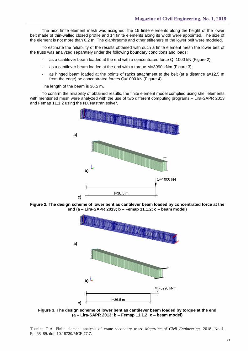
The next finite element mesh was assigned: the 15 finite elements along the height of the lower belt made of thin-walled closed profile and 14 finite elements along its width were appointed. The size of the element is not more than 0.2 m. The diaphragms and other stiffeners of the lower belt were modeled.
To estimate the reliability of the results obtained with such a finite element mesh the lower belt of the truss was analyzed separately under the following boundary conditions and loads:
- as a cantilever beam loaded at the end with a concentrated force Q=1000 kN (Figure 2);
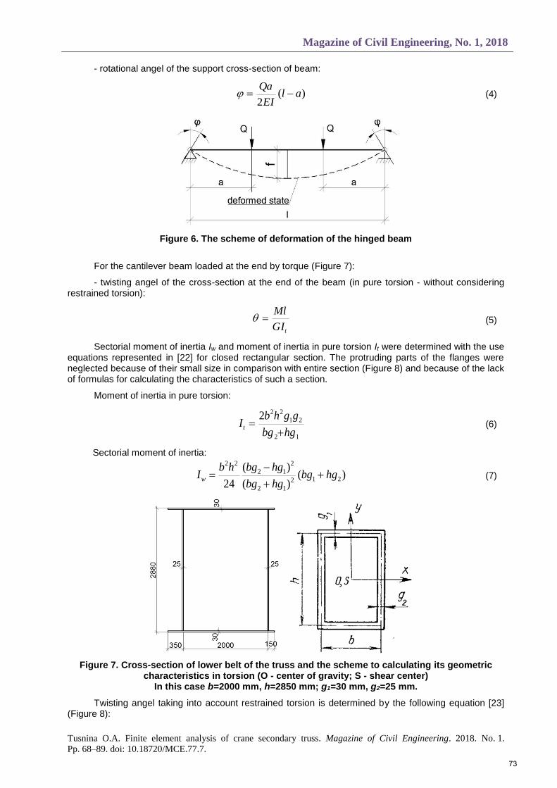
- as a cantilever beam loaded at the end with a torque M=3990 kNm (Figure 3);
- as hinged beam loaded at the points of racks attachment to the belt (at a distance a=12.5 m from the edge) be concentrated forces Q=1000 kN (Figure 4).
The length of the beam is 36.5 m.
To confirm the reliability of obtained results, the finite element model complied using shell elements with mentioned mesh were analyzed with the use of two different computing programs – Lira-SAPR 2013 and Femap 11.1.2 using the NX Nastran solver.
a)
b)
c)
Figure 2. The design scheme of lower bent as cantilever beam loaded by concentrated force at the end (a – Lira-SAPR 2013; b – Femap 11.1.2; c – beam model)
a)
b)
c)
Figure 3. The design scheme of lower bent as cantilever beam loaded by torque at the end (a – Lira-SAPR 2013; b – Femap 11.1.2; c – beam model)
71

Инженерно-строительный журнал, № 1, 2018
Туснина О.А. Конечно-элементное моделирование и расчёт подкраново-подстропильной фермы //
Инженерно-строительный журнал. 2018. № 1(77). С. 68–89.
a)
b)
c)
Figure 4. The design scheme of lower bent as hinge beam (a – Lira-SAPR 2013; b – Femap 11.1.2; c – beam model)
*a=12.5 m is distance taken in accordance with the length of the truss panel
Theoretical equations for displacements and rotational angels are represented below.
For the cantilever beam loaded at the end by concentrated force (Figure 5):
- vertical displacement of the end of the beam is determined by the following equation:
EI
Qlf
3
3
(1)
- rotational angel of the end of the beam:
EI
Ql
2
2
(2)
Figure 5. The scheme of deformation of the cantilever beam loaded by concentrated force at the end
For the hinged beam loaded as mentioned above (Figure 6):
- vertical displacement of the middle of the beam span:
)34(24 3
33
l
a
l
a
EI
Qlf (3)
72
Magazine of Civil Engineering, No. 1, 2018
Tusnina O.A. Finite element analysis of crane secondary truss. Magazine of Civil Engineering. 2018. No. 1.
Pp. 68–89. doi: 10.18720/MCE.77.7.
- rotational angel of the support cross-section of beam:
)(2
alEI
Qa (4)
Figure 6. The scheme of deformation of the hinged beam
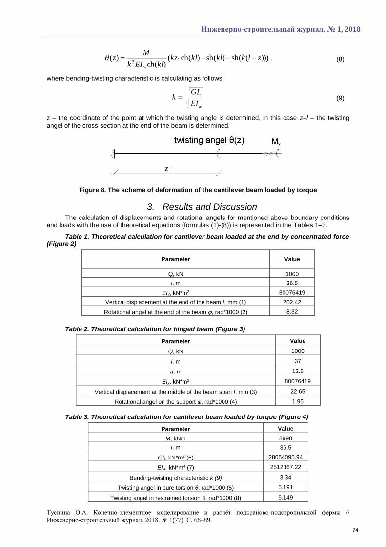
For the cantilever beam loaded at the end by torque (Figure 7):
- twisting angel of the cross-section at the end of the beam (in pure torsion - without considering restrained torsion):
tGI
Ml (5)
Sectorial moment of inertia Iw and moment of inertia in pure torsion It were determined with the use equations represented in [22] for closed rectangular section. The protruding parts of the flanges were neglected because of their small size in comparison with entire section (Figure 8) and because of the lack of formulas for calculating the characteristics of such a section.
Moment of inertia in pure torsion:
12
21
222
hgbg
gghbIt
(6)
Sectorial moment of inertia:
)()(
)(
24212
12
2
12
22
hgbghgbg
hgbghbIw
(7)
Figure 7. Cross-section of lower belt of the truss and the scheme to calculating its geometric characteristics in torsion (O - center of gravity; S - shear center)
In this case b=2000 mm, h=2850 mm; g1=30 mm, g2=25 mm.
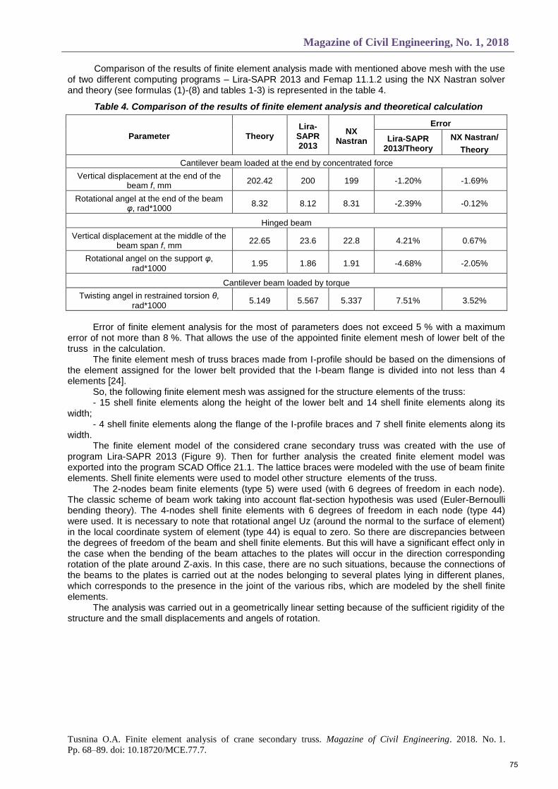
Twisting angel taking into account restrained torsion is determined by the following equation [23] (Figure 8):
73
Инженерно-строительный журнал, № 1, 2018
Туснина О.А. Конечно-элементное моделирование и расчёт подкраново-подстропильной фермы //
Инженерно-строительный журнал. 2018. № 1(77). С. 68–89.
)))((sh)(sh)(ch()(ch
)(3
zlkklklkzklEIk
Mz
w
, (8)
where bending-twisting characteristic is calculating as follows:
w
t
EI
GIk (9)
z – the coordinate of the point at which the twisting angle is determined, in this case z=l – the twisting angel of the cross-section at the end of the beam is determined.
Figure 8. The scheme of deformation of the cantilever beam loaded by torque
3. Results and Discussion The calculation of displacements and rotational angels for mentioned above boundary conditions
and loads with the use of theoretical equations (formulas (1)-(8)) is represented in the Tables 1–3.
Table 1. Theoretical calculation for cantilever beam loaded at the end by concentrated force (Figure 2)
Parameter Value
Q, kN 1000
l, m 36.5
EIy, kN*m2 80076419
Vertical displacement at the end of the beam f, mm (1) 202.42
Rotational angel at the end of the beam φ, rad*1000 (2) 8.32
Table 2. Theoretical calculation for hinged beam (Figure 3)
Parameter Value
Q, kN 1000
l, m 37
a, m 12.5
EIy, kN*m2 80076419
Vertical displacement at the middle of the beam span f, mm (3) 22.65
Rotational angel on the support φ, rad*1000 (4) 1.95
Table 3. Theoretical calculation for cantilever beam loaded by torque (Figure 4)
Parameter Value
M, kNm 3990
l, m 36.5
GIt, kN*m2 (6) 28054095.94
EIw, kN*m4 (7) 2512367.22
Bending-twisting characteristic k (9) 3.34
Twisting angel in pure torsion θ, rad*1000 (5) 5.191
Twisting angel in restrained torsion θ, rad*1000 (8) 5.149
74
Magazine of Civil Engineering, No. 1, 2018
Tusnina O.A. Finite element analysis of crane secondary truss. Magazine of Civil Engineering. 2018. No. 1.
Pp. 68–89. doi: 10.18720/MCE.77.7.
Comparison of the results of finite element analysis made with mentioned above mesh with the use of two different computing programs – Lira-SAPR 2013 and Femap 11.1.2 using the NX Nastran solver and theory (see formulas (1)-(8) and tables 1-3) is represented in the table 4.
Table 4. Comparison of the results of finite element analysis and theoretical calculation
Parameter Theory Lira-
SAPR 2013
NX Nastran
Error
Lira-SAPR 2013/Theory
NX Nastran/
Theory
Cantilever beam loaded at the end by concentrated force
Vertical displacement at the end of the beam f, mm
202.42 200 199 -1.20% -1.69%
Rotational angel at the end of the beam φ, rad*1000
8.32 8.12 8.31 -2.39% -0.12%
Hinged beam
Vertical displacement at the middle of the beam span f, mm
22.65 23.6 22.8 4.21% 0.67%
Rotational angel on the support φ, rad*1000
1.95 1.86 1.91 -4.68% -2.05%
Cantilever beam loaded by torque
Twisting angel in restrained torsion θ, rad*1000
5.149 5.567 5.337 7.51% 3.52%
Error of finite element analysis for the most of parameters does not exceed 5 % with a maximum
error of not more than 8 %. That allows the use of the appointed finite element mesh of lower belt of the truss in the calculation.
The finite element mesh of truss braces made from I-profile should be based on the dimensions of the element assigned for the lower belt provided that the I-beam flange is divided into not less than 4 elements [24].
So, the following finite element mesh was assigned for the structure elements of the truss: - 15 shell finite elements along the height of the lower belt and 14 shell finite elements along its
width; - 4 shell finite elements along the flange of the I-profile braces and 7 shell finite elements along its
width. The finite element model of the considered crane secondary truss was created with the use of
program Lira-SAPR 2013 (Figure 9). Then for further analysis the created finite element model was exported into the program SCAD Office 21.1. The lattice braces were modeled with the use of beam finite elements. Shell finite elements were used to model other structure elements of the truss.
The 2-nodes beam finite elements (type 5) were used (with 6 degrees of freedom in each node). The classic scheme of beam work taking into account flat-section hypothesis was used (Euler-Bernoulli bending theory). The 4-nodes shell finite elements with 6 degrees of freedom in each node (type 44) were used. It is necessary to note that rotational angel Uz (around the normal to the surface of element) in the local coordinate system of element (type 44) is equal to zero. So there are discrepancies between the degrees of freedom of the beam and shell finite elements. But this will have a significant effect only in the case when the bending of the beam attaches to the plates will occur in the direction corresponding rotation of the plate around Z-axis. In this case, there are no such situations, because the connections of the beams to the plates is carried out at the nodes belonging to several plates lying in different planes, which corresponds to the presence in the joint of the various ribs, which are modeled by the shell finite elements.
The analysis was carried out in a geometrically linear setting because of the sufficient rigidity of the structure and the small displacements and angels of rotation.
75
Инженерно-строительный журнал, № 1, 2018
Туснина О.А. Конечно-элементное моделирование и расчёт подкраново-подстропильной фермы //
Инженерно-строительный журнал. 2018. № 1(77). С. 68–89.
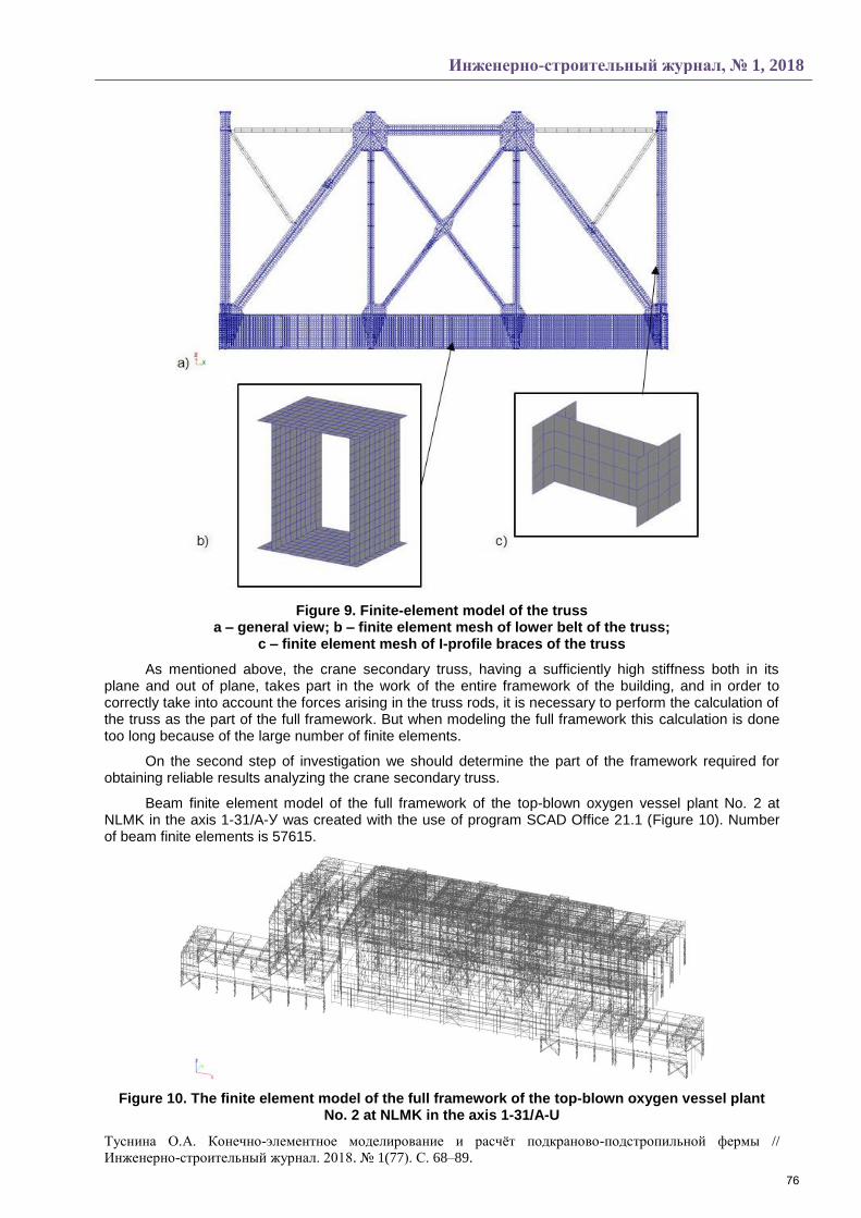
Figure 9. Finite-element model of the truss a – general view; b – finite element mesh of lower belt of the truss;
c – finite element mesh of I-profile braces of the truss
As mentioned above, the crane secondary truss, having a sufficiently high stiffness both in its plane and out of plane, takes part in the work of the entire framework of the building, and in order to correctly take into account the forces arising in the truss rods, it is necessary to perform the calculation of the truss as the part of the full framework. But when modeling the full framework this calculation is done too long because of the large number of finite elements.
On the second step of investigation we should determine the part of the framework required for obtaining reliable results analyzing the crane secondary truss.
Beam finite element model of the full framework of the top-blown oxygen vessel plant No. 2 at NLMK in the axis 1-31/A-У was created with the use of program SCAD Office 21.1 (Figure 10). Number of beam finite elements is 57615.
Figure 10. The finite element model of the full framework of the top-blown oxygen vessel plant No. 2 at NLMK in the axis 1-31/A-U
76
Magazine of Civil Engineering, No. 1, 2018
Tusnina O.A. Finite element analysis of crane secondary truss. Magazine of Civil Engineering. 2018. No. 1.
Pp. 68–89. doi: 10.18720/MCE.77.7.
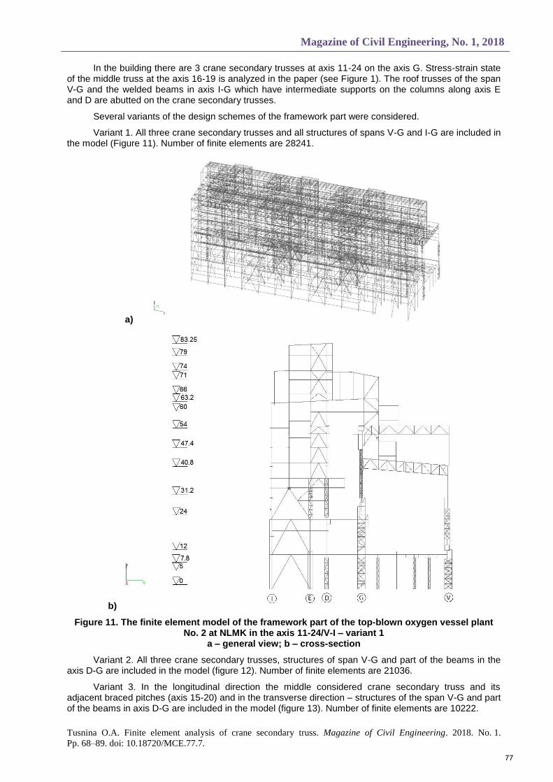
In the building there are 3 crane secondary trusses at axis 11-24 on the axis G. Stress-strain state of the middle truss at the axis 16-19 is analyzed in the paper (see Figure 1). The roof trusses of the span V-G and the welded beams in axis I-G which have intermediate supports on the columns along axis E and D are abutted on the crane secondary trusses.
Several variants of the design schemes of the framework part were considered.
Variant 1. All three crane secondary trusses and all structures of spans V-G and I-G are included in the model (Figure 11). Number of finite elements are 28241.
a)
b)
Figure 11. The finite element model of the framework part of the top-blown oxygen vessel plant No. 2 at NLMK in the axis 11-24/V-I – variant 1
a – general view; b – cross-section
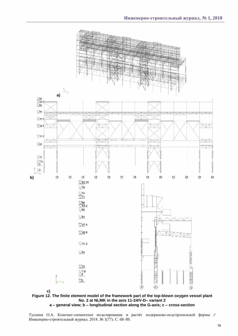
Variant 2. All three crane secondary trusses, structures of span V-G and part of the beams in the axis D-G are included in the model (figure 12). Number of finite elements are 21036.
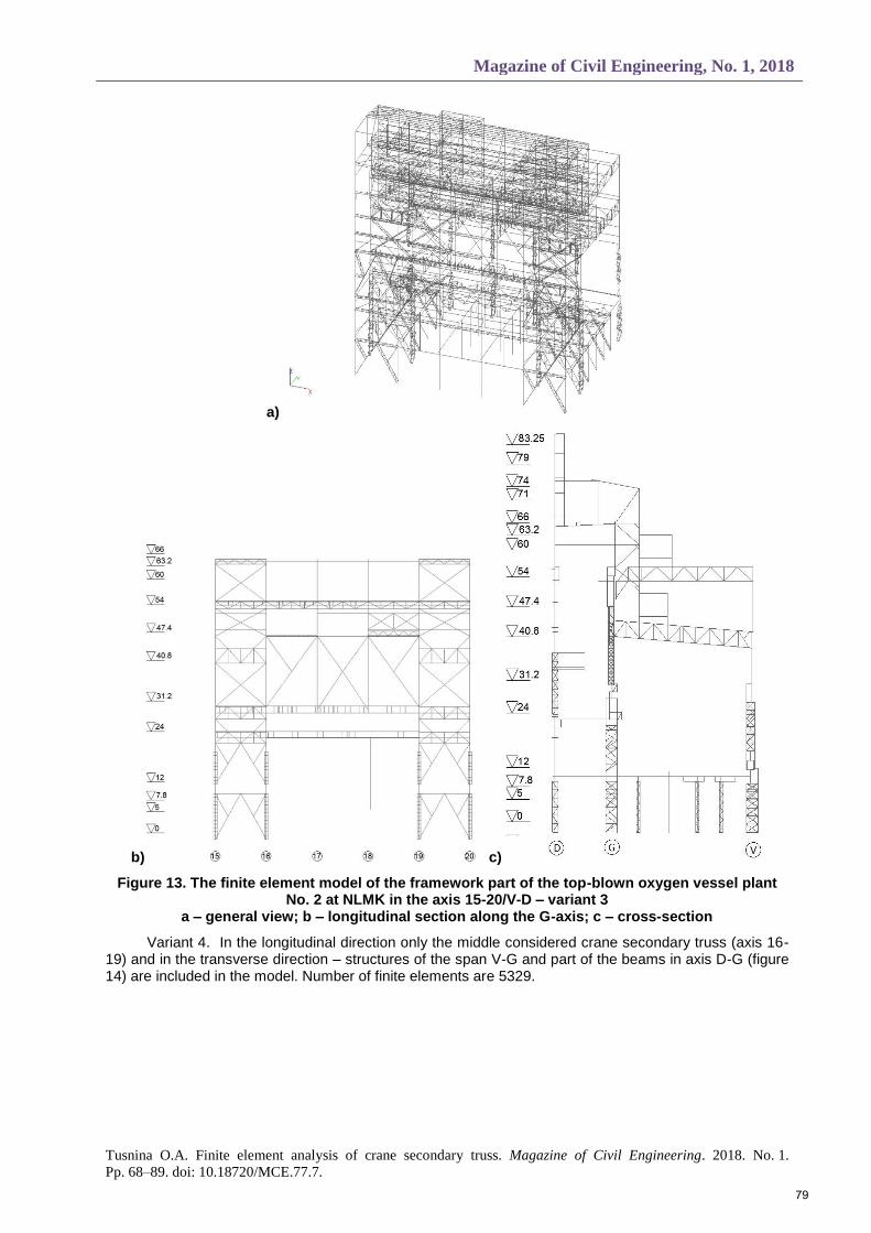
Variant 3. In the longitudinal direction the middle considered crane secondary truss and its adjacent braced pitches (axis 15-20) and in the transverse direction – structures of the span V-G and part of the beams in axis D-G are included in the model (figure 13). Number of finite elements are 10222.
77
Инженерно-строительный журнал, № 1, 2018
Туснина О.А. Конечно-элементное моделирование и расчёт подкраново-подстропильной фермы //
Инженерно-строительный журнал. 2018. № 1(77). С. 68–89.
a)
b)
c) Figure 12. The finite element model of the framework part of the top-blown oxygen vessel plant
No. 2 at NLMK in the axis 11-24/V-D– variant 2 a – general view; b – longitudinal section along the G-axis; c – cross-section
78
Magazine of Civil Engineering, No. 1, 2018
Tusnina O.A. Finite element analysis of crane secondary truss. Magazine of Civil Engineering. 2018. No. 1.
Pp. 68–89. doi: 10.18720/MCE.77.7.
a)
b) c)
Figure 13. The finite element model of the framework part of the top-blown oxygen vessel plant No. 2 at NLMK in the axis 15-20/V-D – variant 3
a – general view; b – longitudinal section along the G-axis; c – cross-section
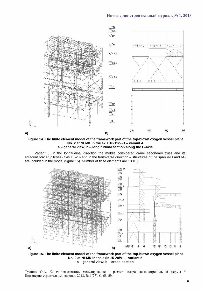
Variant 4. In the longitudinal direction only the middle considered crane secondary truss (axis 16-19) and in the transverse direction – structures of the span V-G and part of the beams in axis D-G (figure 14) are included in the model. Number of finite elements are 5329.
79
Инженерно-строительный журнал, № 1, 2018
Туснина О.А. Конечно-элементное моделирование и расчёт подкраново-подстропильной фермы //
Инженерно-строительный журнал. 2018. № 1(77). С. 68–89.
a) b)
Figure 14. The finite element model of the framework part of the top-blown oxygen vessel plant No. 2 at NLMK in the axis 16-19/V-D – variant 4
a – general view; b – longitudinal section along the G-axis
Variant 5. In the longitudinal direction the middle considered crane secondary truss and its adjacent braced pitches (axis 15-20) and in the transverse direction – structures of the span V-G and I-G are included in the model (figure 15). Number of finite elements are 13316.
a) b)
Figure 15. The finite element model of the framework part of the top-blown oxygen vessel plant No. 2 at NLMK in the axis 15-20/V-I – variant 5
a – general view; b – cross-section
80
Magazine of Civil Engineering, No. 1, 2018
Tusnina O.A. Finite element analysis of crane secondary truss. Magazine of Civil Engineering. 2018. No. 1.
Pp. 68–89. doi: 10.18720/MCE.77.7.
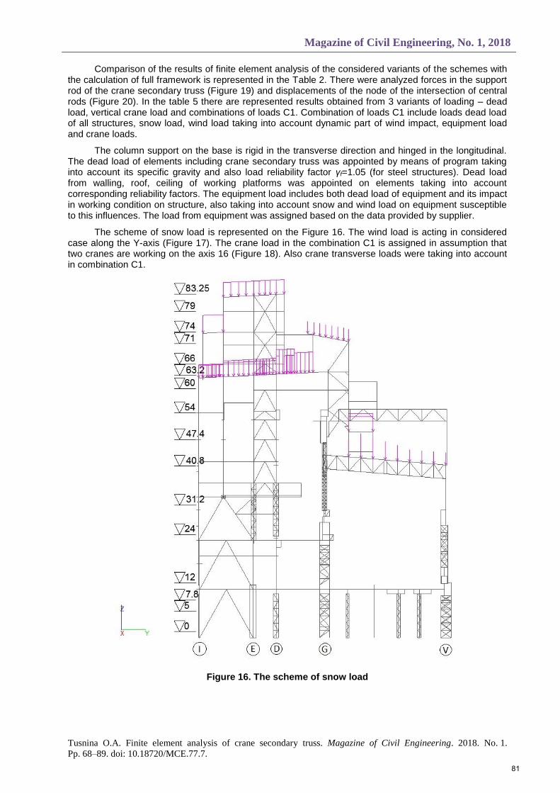
Comparison of the results of finite element analysis of the considered variants of the schemes with the calculation of full framework is represented in the Table 2. There were analyzed forces in the support rod of the crane secondary truss (Figure 19) and displacements of the node of the intersection of central rods (Figure 20). In the table 5 there are represented results obtained from 3 variants of loading – dead load, vertical crane load and combinations of loads C1. Combination of loads C1 include loads dead load of all structures, snow load, wind load taking into account dynamic part of wind impact, equipment load and crane loads.
The column support on the base is rigid in the transverse direction and hinged in the longitudinal. The dead load of elements including crane secondary truss was appointed by means of program taking into account its specific gravity and also load reliability factor γf=1.05 (for steel structures). Dead load from walling, roof, ceiling of working platforms was appointed on elements taking into account corresponding reliability factors. The equipment load includes both dead load of equipment and its impact in working condition on structure, also taking into account snow and wind load on equipment susceptible to this influences. The load from equipment was assigned based on the data provided by supplier.
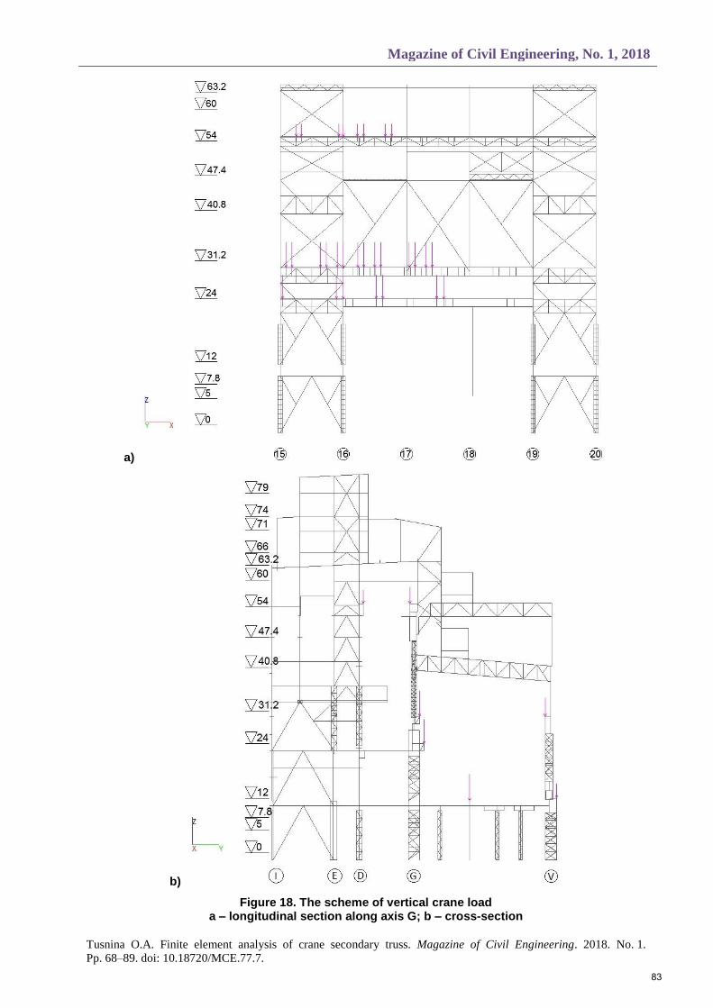
The scheme of snow load is represented on the Figure 16. The wind load is acting in considered case along the Y-axis (Figure 17). The crane load in the combination C1 is assigned in assumption that two cranes are working on the axis 16 (Figure 18). Also crane transverse loads were taking into account in combination C1.
Figure 16. The scheme of snow load
81

Инженерно-строительный журнал, № 1, 2018
Туснина О.А. Конечно-элементное моделирование и расчёт подкраново-подстропильной фермы //
Инженерно-строительный журнал. 2018. № 1(77). С. 68–89.
a)
b)
Figure 17. The scheme of wind load a – general view; b – cross-section
82
Magazine of Civil Engineering, No. 1, 2018
Tusnina O.A. Finite element analysis of crane secondary truss. Magazine of Civil Engineering. 2018. No. 1.
Pp. 68–89. doi: 10.18720/MCE.77.7.
a)
b)
Figure 18. The scheme of vertical crane load a – longitudinal section along axis G; b – cross-section
83

Инженерно-строительный журнал, № 1, 2018
Туснина О.А. Конечно-элементное моделирование и расчёт подкраново-подстропильной фермы //
Инженерно-строительный журнал. 2018. № 1(77). С. 68–89.
Table 5. Comparison of the results of finite element analysis
Variant of scheme Full 1 2 3 4 5
Forces in the support rod from the dead
load
N, t -129 -129 -125 -126 -129 -130
My, tm 215 217 196 171 232 188
Mz, tm 52 52 52 47 -149 47
Forces in the support rod from the vertical
crane load
N, t -720 -722 -721 -715 -724 -717
My, tm 1493 1515 1525 1546 1410 1538
Mz, tm 120 113 107 87 -13 92
Forces in the support rod from the
combination С1
N, t -591 -600 -563 -556 -613 -597
My, tm 1577 1647 1583 1554 1197 1593
Mz, tm -113 -83 -92 -91 -420 -102
Displacement of the central node from
dead load Z, mm -6.23 -6.25 -6.29 -6.12 -7.8 -6.11
Displacement of the central node from
crane load
Y, mm 17.28 17.74 21.9 31.81 47.6 20.59
Z, mm -27.89 -28.22 -28.27 -28.93 -40.55 -28.78
Displacement of the central node from combination С1
Y, mm 35.92 46.56 151.98 163.58 158.01 45.37
Z, mm -29.71 -29.69 -29.66 -29.49 -36.36 -29.76
Number of finite elements 57615 28241 21036 10222 5329 13316
Error in the comparison with full
framework
Forces in the support rod from
the dead load
N, t 0.0% -3.1% -2.3% 0.0% 0.1%
My, tm 0.9% -8.8% -20.5% 7.9% -12.6%
Mz, tm 0.0% 0.0% -9.6% -386.5% -9.6%
Forces in the support rod from
the vertical crane load
N, t 0.3% 0.1% -0.7% 0.6% -0.4%
My, tm 1.5% 2.1% 3.5% -5.6% 3.0%
Mz, tm -5.8% -10.8% -27.5% -110.8% -23.3%
Forces in the support rod from the combination
С1
N, t 1.5% -4.7% -5.9% 3.7% 1.0%
My, tm 4.4% 0.4% -1.5% -24.1% 1.0%
Mz, tm -26.5% -18.6% -19.5% 271.7% -9.7%
Displacement of the central node from dead load
Z, mm 0.3% 1.0% -1.8% 25.2% -1.9%
Displacement of the central node from crane load
Y, mm 2.7% 26.7% 84.1% 175.5% 19.2%
Z, mm 1.2% 1.4% 3.7% 45.4% 3.2%
Displacement of the central node
from the combination С1
Y, mm 22.9% 323.1% 355.4% 339.9% 20.8%
Z, mm -0.1% -0.2% -0.7% 22.4% 0.2%
84

Magazine of Civil Engineering, No. 1, 2018
Tusnina O.A. Finite element analysis of crane secondary truss. Magazine of Civil Engineering. 2018. No. 1.
Pp. 68–89. doi: 10.18720/MCE.77.7.
Figure 19. Axial forces diagram (tons) obtained from analyzing of variant 4 of design scheme from dead load
Figure 20. Vertical displacements (mm) obtained from analyzing of variant 5 of design scheme from dead load (deformed state of structure is shown by blue color)
Based on the analysis of the obtained results, the variant 5 of partial design scheme of framework was adopted as the main for analyzing crane secondary truss taking into account its spatial work in the structure of full framework.
In general these calculations allowed establishing the part of the framework that should be included in a unified calculation scheme with the truss. So, the calculation can be performed for a part of
85

Инженерно-строительный журнал, № 1, 2018
Туснина О.А. Конечно-элементное моделирование и расчёт подкраново-подстропильной фермы //
Инженерно-строительный журнал. 2018. № 1(77). С. 68–89.
the framework in the longitudinal direction within the considered truss and adjacent braced column pitches and in transverse direction – along span on each side.
The crane secondary truss modeled by shell finite elements in accordance with below proven mesh was embedded in the chosen design scheme (variant 5) of the part of framework. This finite element model is shown on the figure 18. Then the analysis of this model was done on the loads acting on the framework of vessel plant.
a)
b)
Figure 21. Finite element model for the analysis of crane secondary truss as part of framework a – general view; b – longitudinal section along the G-axis
It should be noted that the medium-power laptop with an Intel Core i7 processor was used and calculation time of this chosen scheme (Figure 21) did not exceed 10 minutes. So, the calculation in this way is available to a wide range of users and does not take much time.
The results of the analysis of beam finite element model (variant 5) are compared with the results obtained with the use of shell finite elements to model crane secondary truss (Figure 18) in the Table 6.
86

Magazine of Civil Engineering, No. 1, 2018
Tusnina O.A. Finite element analysis of crane secondary truss. Magazine of Civil Engineering. 2018. No. 1.
Pp. 68–89. doi: 10.18720/MCE.77.7.
Table 6. Comparison of the results of numerical calculation made with the use of beam and shell finite elements
Scheme Beams Shells Differences
Displacement of the central node from dead load
Z, mm -6.11 -5.79 -5.24%
Displacement of the central node from snow load
Z, mm -2.48 -2.37 -4.44%
Displacements of the central node from crane load
Y, mm 20.59 23.85 13.67%
Z, mm -28.78 -25.45 -11.57%
Ux, deg -0.39 -0.45 13.33%
Displacements of the central node from combination C1
Y, mm 45.37 39.88 12.12%
Z, mm -29.76 -27.24 -8.47%
As it can be seen the difference in the obtained displacements is no more than 14 %, that allows
us to conclude that the calculation scheme of the framework fragment with the finite element model of the crane secondary truss included in it gives quite reliable results.
Vertical displacements of structure are shown on the Figure 22.
Figure 22. Vertical displacements of structure from dead load (deformed state of structure is shown by blue color)
So, we determined the finite-element model of the truss taking into account its work as the part of framework. This model will be used in further research.
The analyses of stress-strain state of the truss taking into account its current state and defects will be the next stage of the study.
The crane secondary truss is constantly exposed to the cyclic dynamic load from the cranes, which causes the development of fatigue damages in its elements. The lower belt of the truss is the most susceptible to these damages. As it was revealed in the paper [25] the particular attention should be paid to the zones of conjugation of the gussets with the upper flange of the lower belt and its walls with the upper flange at the location of diaphragms.
To analyze the state of the truss and assess the safety of its exploitation, it is necessary to perform a calculation not only for strength, but also for endurance, taking into account the defects already existing defects [18]. The endurance of solid elements (walls, flanges. etc.) is much higher than the endurance of the joint connections of these elements [17].
87
Инженерно-строительный журнал, № 1, 2018
Туснина О.А. Конечно-элементное моделирование и расчёт подкраново-подстропильной фермы //
Инженерно-строительный журнал. 2018. № 1(77). С. 68–89.
This is one more reason to model crane secondary truss with the use of shell finite elements, since in this way it is possible to take into account the presence of all gussets and ribs in the joints and most accurately assess their stress-strain state with the subsequent analysis of its endurance.
4. Conclusions The following conclusions can be made based on the carried out investigations:
1. Analysis of the crane secondary truss should be done with the use of shell finite elements. It is recommended to use finite element mesh with no less than 15 elements along the height of the lower belt of the truss made from thin-walled closed box profile and no less than 4 elements along I-beam flanges. It is advisable to use quadrangular elements with the ratio of sides closed to unity. The use of triangular finite elements is not recommended.
2. Spatial work of the crane secondary truss as a part of full framework should be taken into account. To decrease number of finite elements and time of solving when compiling design scheme it is possible to allocate in the longitudinal direction of the building considered crane secondary truss with the adjacent braced column pitches and in the transverse direction – it is necessary to take into account the structures of adjacent spans.
Reference 1. Yelnov N.A., Kochetova Ye.A. Analiz primeneniya sistem
tipa «podkranovo-podstropilnye fermy» v bolsheproletnykh tsekhakh odnoetazhnykh promyshlennykh zdaniy [Analysis of the application of systems such as "crane-under-trusses" in large-span shops of single-storey industrial buildings]. Trudy nauchnogo kongressa 14-go rossiyskogo arkhitekturno-stroitelnogo foruma [Proceedings of scientific congress of 14th Russian architectural and construction forum]. 2016. Pp. 143–146. (rus)
2. Rukovodstvo po proektirovaniyu stalnykh podkranovykh konstruktsiy [Guidelines for the design of steel crane structures]. Moscow.: TsNIIproektstalkonstruktsiya, 1976. 112 p. (rus)
3. Vlasov V.Z. Tonkostennye uprugie sterzhni [Thin-walled elastic rods]. Moscow: Fizmatgiz, 1959. 568 p. (rus)
4. Umanskiy A.A. Kruchenie i izgib tonkostennykh aviakonstruktsiy [Torsion and bending of thin-walled aircraft constructions]. Moscow: Oborongiz. 1939. 112 p. (rus)
5. Musat S.D., Epureanu B.I. Study of warping torsion of thin-walled beams with closed cross-section using macro-elements. Communications in Numerical Methods in Engineering. 1996. Vol. 12. Pp. 873–884.
6. Li L-Y., Easterbrook D. Free torsion of thin-walled structural members of open and closed-sections. Applied Mathematics and Mechanics. 2014. Vol. 35. No. 1. Pp. 25–32
7. Chiskis A., Parnes R. On torsion of closed thin-wall members with arbitrary stress-strain laws: a general criterion for cross-sections exhibiting no warping. Journal of Applied Mechanics. 2000. Vol. 67. Pp. 460–464.
8. Omidvari A., Hematiyan M. Approximate closed-form formulae for buckling analysis of rectangular tubes under torsion. International Journal of Engineering. 2015. Vol. 28. No. 8. Pp. 1226–1232.
9. Srinivasan V., Purushothaman T., Samrat Chatterjee Stress analysis of thin-walled circular and rectangular tubes subjected to torsion. International Journal of Mechanical Engineering and Technology. 2017. Vol. 8. No. 8. Pp. 1580–1587.
10. Doostfatemeh A., Hematiyan M., Arghavan S. Closed-form approximate formulas for torsional analysis of hollow tubes with straight and circular edges. Journal of Mechanics. 2009. Vol. 25. No. 4. Pp. 401–409.
11. Mentrasti L. Torsion of closed cross-section thin-walled beams: the influence of shearing strain. Thin-Walled Structures. 1987. Vol. 5. No. 4. Pp. 277–305.
12. Mentrasti L. Distortion (and torsion) of rectangular thin-walled beams. Thin-Walled Structures. 1990. Vol. 10. No. 3. Pp. 175–193.
13. Kujawa M. Elastic distortional buckling of thin-walled bars of closed quadratic cross-section. Mechanics and
Литература 1. Ельнов Н.А., Кочетова Е.А. Анализ применения систем
типа «подкраново-подстропильные фермы» в большепролетных цехах одноэтажных промышленных зданий // Труды научного конгресса 14-го российского архитектурно-строительного форума. 2016. С. 143–146
2. Руководство по проектированию стальных подкрановых конструкций. М.: ЦНИИпроектстальконструкция, 1976. 112 с.
3. Власов В.З. Тонкостенные упругие стержни. М: Физматгиз, 1959. 568 с.
4. Уманский А.А. Кручение и изгиб тонкостенных авиаконструкций. М.: Оборонгиз. 1939. 112 с.
5. Musat S.D., Epureanu B.I. Study of warping torsion of thin-walled beams with closed cross-section using macro-elements // Communications in Numerical Methods in Engineering. 1996. Vol. 12. Pp. 873–884.
6. Li L-Y., Easterbrook D. Free torsion of thin-walled structural members of open and closed-sections // Applied Mathematics and Mechanics. 2014. Vol. 35. № 1. Pp. 25–32
7. Chiskis A., Parnes R. On torsion of closed thin-wall members with arbitrary stress-strain laws: a general criterion for cross-sections exhibiting no warping // Journal of Applied Mechanics. 2000. Vol. 67. Pp. 460–464.
8. Omidvari A., Hematiyan M. Approximate closed-form formulae for buckling analysis of rectangular tubes under torsion // International Journal of Engineering. 2015. Vol. 28. No. 8. Pp. 1226–1232.
9. Srinivasan V., Purushothaman T., Chatterjee S. Stress analysis of thin-walled circular and rectangular tubes subjected to torsion // International Journal of Mechanical Engineering and Technology. 2017. Vol. 8. № 8. Pp. 1580–1587.
10. Doostfatemeh A., Hematiyan M., Arghavan S. Closed-form approximate formulas for torsional analysis of hollow tubes with straight and circular edges // Journal of Mechanics. 2009. Vol. 25. No. 4. Pp. 401–409.
11. Mentrasti L. Torsion of closed cross-section thin-walled beams: the influence of shearing strain // Thin-Walled Structures. 1987. Vol. 5. № 4. Pp. 277–305.
12. Mentrasti L. Distortion (and torsion) of rectangular thin-walled beams // Thin-Walled Structures. 1990. Vol. 10. № 3. Pp. 175–193.
13. Kujawa M. Elastic distortional buckling of thin-walled bars of closed quadratic cross-section // Mechanics and Mechanical Engineering. 2013. Vol. 17. № 2. Pp. 119–126.
14. Gonçalves R., Camotim D. Buckling behaviour of thin-walled regular polygonal tubes subjected to bending or torsion // Thin-Walled Structures. 2013. Vol. 73. Pp. 185–197.
15. Туснин А.Р. Особенности взаимодействия мембраны,
88
Magazine of Civil Engineering, No. 1, 2018
Tusnina O.A. Finite element analysis of crane secondary truss. Magazine of Civil Engineering. 2018. No. 1.
Pp. 68–89. doi: 10.18720/MCE.77.7.
Mechanical Engineering. 2013. Vol. 17. No. 2. Pp. 119–126.
14. Gonçalves R., Camotim D. Buckling behaviour of thin-walled regular polygonal tubes subjected to bending or torsion. Thin-Walled Structures. 2013. Vol. 73. Pp. 185–197.
15. Tusnin A.R. Osobennosti vzaimodeystviya membrany, prikreplennoy s ekstsentrisitetom k opornomu konturu iz zamknutykh tonkostennykh pryamougolnykh profiley. [Features of interaction of a membrane attached with eccentricity to support contour from closed thin-walled rectangular sections]. Industrial and Civil Engineering. 2013. No. 12. Pp. 47–50. (rus)
16. Eremin K.I., Shulga S.N. Modelirovanie razvitiya ustalostnykh povrezh¬deniy v podkranovo-podstropil'nykh fermakh [Simulation of fatigue damages in secondary truss of crane]. Proceedings of Moscow State University of Civil Engineering. 2014. No. 2. Pp. 30–38. (rus)
17. Eremin K.I., Shulga S.N. Napryazhenno-deformirovannoe sostoyanie uzlov podkranovo-podstropilnykh ferm [Stressed-strained state of crane-rafter trusses joints]. Industrial and Civil Engineering. 2012. No. 7. Pp. 52–55. (rus)
18. Shulga S.N. Metodika otsenki zhivuchesti i opredelenie ostatochnogo resursa podkranovo-podstropilnykh ferm s treshchinopodobnymi defektami [Method for assessing survivability and determining the residual resource of cranial-substratum trusses with crack-like defects]. Science and Safety. 2014. No. 4(13). Pp. 2–32 (rus)
19. Eremin K.I., Shulga S.N. Vliyanie ekstsentrisiteta na napryazhenno-deformirovannoe sostoyanie verkhney zony stenok podkranovo-podstropilnykh ferm [Effect of eccentricity on the stress-strain state of the upper zone of the walls of the cranio-sub-spine trusses]. Science and Safety. 2015. No. 5(18). Pp. 49–52 (rus)
20. Brikkel D.M. Analiz NDS podkranovo-podstropilnoy fermy (PPF) na stadii rosta ustalostnoy treshchiny [Analysis of the stress-strain statepf the crane-sub-vertebral truss (PPF) at the stage of fatigue crack growth] Materialy mezhdunarodnoy nauchno-prakticheskoy konferentsii «Nauka segodnya: zadachi i puti ikh resheniya» [Proceeding of international scientific and practical conference “Science today: tasks and ways to solve them]. 2017. Pp. 10–11. (rus)
21. Shulga S.N. Ostatochnyy resurs podkranovo-podstropilnykh ferm s nerazreznym nizhnim poyasom na stadii rosta ustalostnoy treshchiny [Residual resource of cranewing-under-truss trusses with continuous underside belt at the stage of fatigue crack growth]. Doctoral Thesis 05.23.01. Moscow, 2015. 133 p. (rus)
22. Brudka Ya., Lubinski M. Legkie stalnye konstruktsii [Light-weight steel structures]. Moscow: Stroyizdat, 1974. 331 p. (rus)
23. Bychkov D.V. Stroitelnaya mekhanika strzhnevykh tonkostennykh konstruktsiy. Moscow: Gosstroyizdat. 1962. 474 p. (rus)
24. Tusnin A.R. Raschet i proektirovanie konstruktsiy iz tonkostennykh sterzhney otkrytogo profilya [Analysis and design of thin-walled structures with open profile]: abstract of Doctoral Thesis 05.23.01. Moscow, 2003. 353 p. (rus)
25. Yeremin K.I., Shulga S.N. Zakonomernost povrezhdeniy podkranovo-podstropilnykh ferm na stadii ekspluatatsii. [Stressed-strained state of crane-rafter trusses joints]. Industrial and Civil Engineering. 2013. No. 4. Pp. 34–36. (rus)
26. Belyayev N.M. Soprotivleniye materialov. [Resistance of materials] Moscow: Izdatelstvo «Nauka». 1976. 608 p. (rus)
прикреплённой с эксцентриситетом к опорному контуру из замкнутых тонкостенных прямоугольных профилей // Промышленное и гражданское строительство. 2013. № 12. С. 47–50.
16. Еремин К.И., Шульга С.Н. Моделирование развития усталостных повреждений в подкраново-подстропильных фермах // Вестник МГСУ. 2014. № 2. С. 30–38.
17. Еремин К.И., Шульга С.Н. Напряженно-деформированное состояние узлов подкраново-подстропильных ферм // Промышленное и гражданское строительство. 2012. № 7. С. 52–55.
18. Шульга С.Н. Методика оценки живучести и определение остаточного ресурса подкраново-подстропильных ферм с трещиноподобными дефектами // Наука и безопасность. 2014. № 4(13). С. 2–32.
19. Еремин К.И., Шульга С.Н. Влияние эксцентриситета на напряженно-деформированное состояние верхней зоны стенок подкраново-подстропильных ферм // Наука и безопасность. 2015. № 5(18). С. 49–52.
20. Бриккель Д.М. Анализ НДС подкраново-подстропильной фермы (ППФ) на стадии роста усталостной трещины // Материалы международной научно-практической конференции «Наука сегодня: задачи и пути их решения». 2017. С. 10–11.
21. Шульга С.Н. Остаточный ресурс подкраново-подстропильных ферм с неразрезным нижним поясом на стадии роста усталостной трещины: дис. … канд. техн. наук 05.23.01. Москва, 2015. 133 с.
22. Брудка Я., Лубиньски М. Легкие стальные конструкции. М.: Стройиздат, 1974. 331 с.
23. Бычков Д.В. Строительная механика стржневых тонкостенных конструкций. М.: Госстройиздат. 1962. 474 с.
24. Туснин А.Р. Расчет и проектирование конструкций из тонкостенных стержней открытого профиля: автореф. дис. … д-ра. техн. наук 05.23.01. Москва, 2003. 353 c.
25. Еремин К.И., Шульга С.Н. Закономерность повреждений подкраново-подстропильных ферм на стадии эксплуатации // Промышленное и гражданское строительство. 2013. № 4. С. 34–36.
26. Беляев Н.М. Сопротивление материалов. М.: Издательство «Наука». 1976. 608 с.
Olga Tusnina, +7(910)476-16-77; [email protected]
Ольга Александровна Туснина, +7(910)476-16-77; эл. почта: [email protected]
© Tusnina O.A., 2018
89