finishing technology, kinnelon, nj - infohouseinfohouse.p2ric.org/ref/28/27452.pdf · finishing...
TRANSCRIPT

Finishing Technology, Kinnelon, NJ /&= Rinsing is thc rcmoval of a harmful clinging film of proccsa wlution from il woikpiccc
by substituting in its placc an innocuous film of water. Eflicicnt rinsing thcn compriscs achieving the desired end while expending as little work or “effort” as possible.
In general, it is necessary to thoroughly rinse the work between the various treatment stages. For example, ware carrying off an unrinsed film of alkaline cleaning solution would quickly contaminate a subsequent acid pickle, which if in its turn went unrinsed would rapidly contaminate the plating bath. Subjecting the work to a high level of contamination in the rinsc tanks can also cause passivation of the work surface or encourage prccipitation of reaction products on the work. And if the final processing solution IS not propcrly rinsed, salt spotting will occur which may cause etching or be otherwise harmful, and in any case will be unattractive. Thus it is necessary to dilute the clinging film of process solution to such an extent that problems such as salt staining and contamination of subsequent processes are limited to manageable levels.
The literature will give advice concerning what dilution ratio is usually required in rinse tanks. A very general rule of thumb is that a dilution ratio of 1000: 1 is a good starting point in! many cases. Then trail-and-error or a more rigorous statistical process control approach can be employed to get a more exacting answer.
EQUILIBRIUM RINSING The best approach to understanding a complex phenomena usually is to begin with the
obvious and build upon it. So picture an empty mixing vat. Then envision adding to this vat 1 part OF concentrated plating solution and 999 parts of water, and thoroughly stirring the mixture. The mixture will be 1 part plating solution per 1000 total parts, or 0.1% concentration.
The next step in extending our understanding of rinsing is to comprehend what is known as an equilibrium process. Start with the same 1000 parts of 0.1% mixture but, instead of leaving well enough alone, continue to add plating solution and water, in the ratio of 1:999, until the mixing vat overflows. Without going into elaborate proofs, recognize that things are in balance here. The vat contained a 0.1% solution and what we’re adding is a 0.1% solution, so what is overflowing must be a 0.1% solution also.
Now imagine that we had started this process of continuously overflowing the vat years ago, and that it has continued unintenupted ever since. We are confident that the overflowing rinsewater is and always has been of 0.1% concentration. Then someone tells us that they hate to break this bad news . . . but years ago when the experiment was started they had forgotten to add the 1 part plating solution; effectively, we had started with 1000 parts water instead. Our intuition tells us that the concentration in the overflow today can’t possibly be dramatically influenced by the starting conditions all those years ago, and our intuition is right: the system long ago reached a condition so close to equilibrium that the difference is unmeasurable.
This is what we mean when we say a process approaches an equilibrium condition; it really doesn’t matter whether the vat originally contained the desired 1:999 mixture, or was pure water, or was straight plating solution. If we have added liquid in the ratio of one part plating solution to 999 parts water for a substantial enough period of time, then for all practical purposes the concentration in the vat is one part to 999 regardless of the initial conditions. This is the real world situation in the majority of rinsing applications.
SALT IN EQUALS SALT OUT The equilibrium condition for a rinse tank is succinctly described with one simple
equation whose logic is irrefutable:
125

3
90
4
bb
bm
DRAG I N DRAG0 VER DRAGOUT qg = 1 void li = 1 vol. , , , , = 1 vol.
A d v u
PROCESS
Conc. = 100%
I NIT I AL RINSE
Conc. = 3.16%
. . . . . . . . . . . . . . . . . . . . . . . . . . . . . . . . . . . . . . . . . . . . . . . . . . . . . . . . . . . . . . . . . . . . . . . . . . . . . . . . . . . . . . . . . . . . . . . . . . . . . . . . . . . . . . . . . . . . . . . . . . . . . . . . . . . . . . . . . . . . . . . . . . . . . . . . . . . . . . . . . . . . . . . . . . . . . . . . . . . . . . . . . . . . . . . . . . . . . . . . . . . . . . . . . . . . . . . . . . . . . . . . . . . . . . . . . . . . . . . w . . . . . . . . . FINAL
RINSE Conc. = 0.1%
0 VERF LO W OVERFLOW = 30.6 vol. ’ = 30.6 vol.
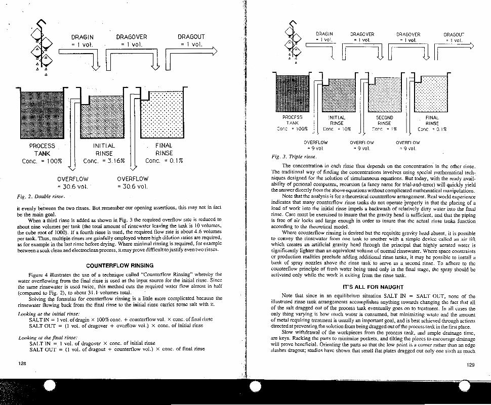
Fig. 2 . Double rinse.
it evenly between the two rinses. But remember our opening assertions, this may not in fact be the main goal.
When a third rinse is added as shown in Fig. 3 the required overflow rate is reduced to about nine volumes per tank (the total amount of rinsewater leaving the tank is 10 volumes, the cube root of 1000). If a fourth rinse is used, the required flow rate is about 4.6 volumes per tank. Thus, multiple rinses are gainfully employed where high dilution ratios are required, as for example in the last rinse before drying. Where minimal rinsing is required, for example between a soak clean and electroclean process, it may prove difficult to justify even two rinses.
COUNTERFLOW RINSING
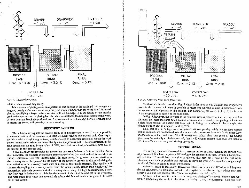
Figure 4 illustrates the use of a technique called “Counterflow Rinsing’’ whereby the water overflowing from the final rinse is used as the input source for the initial rinse. Since the same rinsewater is used twice, this method cuts the required water flow almost in half (compared to Fig. 2), to about 31.1 volumes total.
Solving the formulas for counterflow rinsing is a little more complicated because the rinsewater flowing back from the final rinse to the initial rinse carries some salt with it.
Looking at the initial rinse: SALTIN = 1 vol. ofdragin x 100%conc. + counterflowvol. X conc. offinalrinse SALT OUT = (1 vol. of dragover + overflow vol.) x conc. of initial rinse
Looking at the final rinse: SALT IN = 1 vol. of dragover X conc. of initial rinse SALT OUT = (1 vol. of dragout + counterflow vol.) X conc. of final rinse
PROCESS TANK
Conc. = 100%
DRAGOVER DRAGOVER DRAGOUT = 1 vol = 1 VOI
“I* U
1 r
INITIAL RINSE I Conc. = 10%
V U
1 r
SECOND RINSE
Conc. = 1 % I
UU
. . . . . . . . . . . . . . . . . . . . . . . . . . . . . . . . . . . . . . . . . . . . . . . . . . . . . . . . . . . . . . . . . . . . . . . . . . . . . . . . . . . . . . . . . . . . . . . . . . . . . . . . . . . . . . . . . . . . . . . . . . . . . . . . . . . . . . . . . . . . . . . . . . . . . . . . . . . . . . . . . . . . . . . . . . . . . . . . . . . . . . . . . . . . . . . . . . . . . . . . . . . . . . . . . . . . . . . . . . . . . . . . . . . . . . . . . . . . . . . FINAL RINSE rr Conc. = 0 1 %
OVERFLOW OVERFLOW OVERFLOW = 9 vol. = 9 vol. = 9 VOI.
. . Fig. 3. Triple rinse.
The concentration in each rinse thus depends on the concentration in the other rinse. The traditional way of finding the concentrations involves using special mathematical tech- niques designed for the solution of simultaneous equations. But today, with the ready avail- ability of personal computers, recursion (a fancy name for trial-and-error) will quickly yield the answer directly from the above equations without complicated mathematical manipulations.
Note that the analysis is for a theoretical counterflow arrangement. Real world experience indicates that many counterflow rinse tanks do not operate properly in that the placing of a load of work into the initial rinse impels a backwash of relatively dirty water into the final rinse. Care must be exercised to insure that the gravity head is sufficient, and that the piping is free of air locks and large enough in order to insure that the actual rinse tanks function according to the theoretical model.
Where counterflow rinsing is desired but the requisite gravity head absent, it is possible to convey the rinsewater from one tank to another with a simple device called an,air lift which creates an artificial gravity head through the principal that highly aerated water is significantly lighter than an equivalent volume of normal rinsewater. Where space constraints or production realities preclude adding additional rinse tanks, it may be possible to install a bank of spray nozzles above the rinse tank to serve as a second rinse. To adhere to the counterflow principle of fresh water being used only in the final stage, the spray should be activated only while the work is exiting from the rinse tank.
IT’S ALL FOR NAUGHT Note that since in an equilibrium situation SALT IN = SALT OUT, none of the
illustrated rinse tank arrangements accomplishes anything towards changing the fact that all of the salt dragged OLH of the process tank eventually goes on to treatment. In all cases the only thing varying is how much water is consumed, but minimizing waste and the amount of metal requiring treatment is usually an important goal, and is best achieved through actions directed at preventing the solution from being dragged out of the process tank in the first place.
Slow withdrawal of the workpieces from the process tank, and ample drainage time, are keys. Racking the parts to minimize pockets, and tilting the pieces to encourage drainage will prove beneficial. Orienting the parts so that the low point is a comer rather than an edge slashes dragout; studies have shown that small flat plates dragged out only one sixth as much
128 129
DRAG I N DRAG0 VER DRAGOUT = 1 vol.
7 = 1 vol.
PROCESS I NIT I AL RINSE
Conc. = 100% Conc. = 3.21%
OVERFLOW = 31.1 Val.
TANK li Fig. 4 . Counterf2ow rinse.
solution when racked diagonally.
FINAL RINSE
Conc. = 0.1%
Maintenance of plating racks is important so that bubbles in the coating do not exaggerate dragout; poorly maintained racks may drag out more solution than the work itself. In barrel plating, specifying a large perforation size will aid drainage. It is the nature of the plastics used in the construction of plating barrels, when subjected to the tumbling action of the work, to peen over and block the perforations. An investment in replacement barrels, or manpower to redrill the holes, will probably prove rewarding.
RECOVERYSYSTEMS
The solution having left the process tank, all is not necessarily lost. It may be possible to retum a portion of the solution or at least its metal value to the process tank. One way to do this is with a dragiddragout tank, which consists of a stagnant rinse tank which the work enters immediately before and immediately after the process tank. The concentration in this tank approaches an equilibrium value of 50%, such that each load processed retums half of its dragout to the process tank.
There are many technologies for recovering process solutions or their metal values from the rinsewater, for example evaporation and electrowinning (see section titled Waste Minimi- zation - Alternate Recovery Technologies). In most cases, the greater the concentration in the recovery rinse, the greater the efficiency of the recovery process so that maximizing the concentration in the recovery rinses may be a goal of the rinsing strategy. This usually will suggest decoupling the recovery rinse from the other rinses, rather than employing the counterflow principle because with the recovery rinse being of a high concentration, a very low flow rate is desireable to minimize the amount of chemical carried off in the overflow. The more dilute final rinses can have a fairly substantial flow without carrying much chemical out of the system.
n 0 DRAG I N DRAGOVER DRAGOUT
. .
PROCESS 1 I:;;: 1 FINAL TANK RINSE
Conc. = 3.1% Conc. = 0.1% conc. = 100%
OVERFLOW = 30.6 vol.
OVERFLOW = 30.1 vol.
Fig. 5. Recovery from high flow rinse.
To illustrate this fact, consider Fig. 5 which is the same as Fig. 2 except that evaporative losses in the process tank make it possible to retum one-half the volume of rinsewater from the recovery tank. Operated in this fashion, and comparing the results to Fig. 2, the benefit of the evaporation is shown to be negligible.
In Fig. 6, however, the flow rate in the recovery rinse is reduced so that the concentration can build up. Then the same small volume of rinsewater retumed to the plating tank carries a significant amount of plating salt back with it. Using the numbers in the cxamplc, thc plating solution lost to dragout is cut by 25%.
Note that this advantage was not gained without penalty: while we reduced wasted plating solution, we needed to drastically increase the rinsewater flow to hold the same 0. I % concentration in the final rinse. This illustrates two points: first, that some of the rinsing goals may be mutually exclusive; second, that it will usually require more than two tanks to effect an efficient recovery and rinsing operation.
PERFECT MIXING The rinsing equations discussed above assume perfect mixing, meaning the surface film
of process solution has completely diffused into the general rinsewater, forming a homogene- ous solution. If insufficient rinse time is allowed this may not always be the real world situation; nor may it be possible and practical to leave the work in the rinse tank long enough for this diffusion reaction to reach completion.
Agitation methods that allow convection effects to hasten the diffusion will improve rinsing efficiency. Air agiiation, cathode rocker agitation, or other mixing methods may help achieve this end (see section titled “Solution Agitation and Mixing”).
An easy method which is effective in improving rinsing efficiency is “double-dipping”, simply immersing the work in the rinse, removing it, and re-immersing. This has bctan
130 131

PROCESS TANK
Conc. = 100%
DRAGOVER = 1 vol.
DRAGOUT = 1 vol.
r
FINAL ':I:! 1 RINSE Conc . = 0.1% Conc . = 50%
OVERFLOW OVERFLOW = 0.5 vel: = 499 vol.
Fig. 6 . Recovery rinsing.
demonstrated to be effective with racked work, and would be expected to be even more beneficial in barrel plating.
RINSE TANK DESIGN
Care should go into the design of rinse tanks so that they may operate as efficiently as possible. The overflow weir must be level and full length to minimize shortcircuiting; lacking a level overflow weir, the fresh water added to the tank will take the path of least resistance rather than mixing thoroughly with the contents of the tank. This would be wasteful of water since the oveflowing wastewater would then be less concentrated than the tank contents.
Equally important to promote good mixing is for the fresh water inlet to be brought to the bottom of the tank and be distributed via a perforated sparge pipe. As noted in the earlier discussion of counterflow rinsing, it is extremely important that sufficient gravity head exist, and the details of the design be properly executed, to preclude a backwash of dirty water from the initial rinse to the final rinse.
MINIMIZING WATER USAGE
Once the desired dilution ratio is known, equipment may be installed that will help hold the concentration of contaminants down to the desired level with minimum waste. For example, a timer and solenoid valve can be rigged to deliver a fixed quantity of water to the rinse tanK with each load; the timer can be actuated by foot treadle, limit switch, or, in the case of automatic lines, from the machine's control system.
If loads vary in frequency and dragout volume, a better solution may be to employ a conductivity controller which is adjusted to feed additional rinse water only when contaminant concentration exceeds the acceptable level. It is almost always worthwhile to incorporate flow restrictors, which are simple plumbing devices designed to govem the flow of fresh water to the rinse tanks, holding it to the desired setting despite fluctuations in water pressure.
i
I 132
DEIONIZATION FOR ELECTROPLATING
by Stanley Hirsch
Leeam Consultants, Ltd., New Rochelle, NY
Watcr is an csscntial component of Ihc clcctroplnting procc steps from the beginning to the end. The purity of the water in respect to its mineral and organic content critically affects the quality of the plated part.
FUNDAMENTALS OF DEIONIZATION
The water used in so many metal finishing processes is simply a solution of various inorganic salts. These dissolved impurities are cations (positively charged particles) and anions (negatively charged particles).
The process of deionization or demineralization as applied to the treatment of water involves the exchange of ions to remove any or all dissolved ionic impurities from the water. Because of the developments in the process of deionization, water of the highest quality is readily available, in ample quantity and at reasonable cost. Although there is careful quality control of the chemicals used in metal finishing, little attention has been given to the effects of the impurities in the process water.
The ions most frequently found and their characteristics are outlined in Table I. Two of the most common cations are calcium and magnesium, associated with the
characteristic of water hardness. The ion exchange process for removal of these cations is known as softening. The alkalinity of water derives from the bicarbonate, carbonate and hydroxide ions. These are removed through ion exchange called dealkalization.
Silica and carbon dioxide exist as weakly dissociated ions in natural water and can also be removed by ion exchange. It is most important to remove silica (SiO,) when the water is to be used in a hot bath. Silica, when heated, acts similarly to calcium and magnesium and forms a scale which is very difficult to remove. Most nonionic organic compounds are not removed by ionic exchange.
Ion exchange resins are insoluble electrolytes consisting of a high concentration of polar groups (acidic or basic) incorporated in a synthetic, resinous polymer vehicle. These resins are either cation exchangers or anion exchangers. Reactions of both types in<olve simple ionic equilibria. In the following typical reactions, R- represents the cationic polymeric resin, R + represents the anionic polymeric resin, M' the cation, and X - the anion.
Table I. Dissolved Impurities in Water
lolls Impurity Water Characteristic Removal Process*
Cations Ca+2 Softening Hardness Hardness Softening
Anions
K +
c1-2 so,-2 HCO, ; Alkalinity Dealkalization co, - Alkalinity Dealkalization
Dealkalization OH-' Alkalinity
Weakly SiO, dissociated ions CO,
"The rcninvil prnccrs for any or all ions is callcd demineralization.
133

c R-H+ + M + X - + R-M+ + H + X -
R+OH- + M f X - --z R+X- + M f O H - ( 1 )
(2) Equation (1) shows a strong acid type cationic resin exchanger and equation (2) a strong anionic resin exchanger.
These equations demonstrate the process of water demineralization. When water contain- ing minerals contacts a cationic exchange resin dissolved in the hydrogen form, the effluent will be. the acid of the anions present. The acid is then stripped of the anions by flowing through an anionic exchange resin in the basic form. This is the basis of multiple bed demineralization.
With this system water can be produced with a specific resistance of 250,000 to I ,000,000 ohm-cm. The total electrolyte content in water treated this way can be as low as two parts per million. The small amount of solids still remaining after the two bed treatment is attributed to the complete reversibility of the reaction. Some salt must inevitably leak through the bed.
To obtain water with greater purity, the acid form must be removed as quickly as it is generated, allowing the reaction to proceed to completion. Systems to accomplish this have becn devised using alternating beds of cation and anion exchangers.
Subsequent systems have been developed where it is possible to mix the cation and anion resins in one column, therefore having an infinite number of cationic and anionic exchanges as the water flows through the single column mixed-bed demineralizer. This will produce water with the highest purity obtainable, 0. IO ppm. The theoretical maximum quality of water that can be produced would have a specific resistance of 26,000,000 ohm-cm. Table I1 compares water purity as related to its method of production.
Table 11. Purity of Water Obtained from Various Production Methods
Water Production Method Purity*
Water after 28 distillations in quartz - - - - - - - - - - - - - - - - - - - - - - - - - - 23,000,000 Water treated by mixed-bed resin system - - - - - - - - - - - - - - - - - - - - - - - 18,000,000 Water after three distillations in glass - - - - - - - - - - - - - - - - - - - - - - - - - - 1,000,000 Water after a single distillation in glass - - - - - - - - - - - - - - - - - - - 250,000 to 500,000 Water treated by a multi-bed resin system - - - - - - - - - - - - - - - 250,000 to 1,000,000
*Specific resistance in ohm-cm,.
APPLICATIONS OF DEIONIZED WATER FOR PLATING The quality of the water used in plating is a factor affecting the plating results in terms
of the following characteristics: adhesion, brightness, uniformity, smoothness, pitting, spot- ting, staining and clarity of deposit. Water can be obtained from several sources, including raw surface water from rivers, lakes, etc.; raw groundwater from wells; and treated water from municipal reserqoirs. The various components in these waters which can cause problems in plating operations will vary widely. Generally, the reservoir water is of a higher quality and is more consistent in its composition than either raw surface or raw groundwater.
In the plating cycle, there are four major stages in which water is used: I . Rinsing of parts prior to plating. 2. Make up of plating solutions. 3. Replenishment of plating solutions because of evaporation and drag-out losses. 4. Final rinsing of the plated article before drying. How important it is to use deionized water depends on both the source of the water and
the particular step of the plating cycle. It is necessary to use the highest quality deionized water for replenishment of solutions
where evaporation and drag-out have occurred. When plating at temperatures above room temperature, the plating baths are evaporators and therefore concentrators. If the water used to replace water lost through evaporation contains dissolved solids, the solids will not be evaporated but, rather, will concentrate in the bath and thus cause plating problems.
Ranking next in importance is the water used to make up the plating solutions. The
.
Mihpore Corporation
Your Source for
Water Purification and Fluid Filtration
Choose from:
Ionpure continuous deionization systems for consistent water quality without
regeneration.
Reverse osmosis, ultrafiltration and deionization systems for a variety of high
purity water applications.
Filter cartridges for cost-eff icient clarification and prefiltration.
+
+
+
For more information, call toll-free 1-800-225-1380. I n Massachusetts call 617-275-9200.
MILLIPORE
134

Na Na
(Chloride) (Carbonate) (Fluoride) (Sulfate)