finishing mowers - priefert manufacturing operation manual v3 1011.pdf · finishing mowers fmx500...
TRANSCRIPT

Finishing Mowers FMX500 and FMX600 Models
Operator’s Manual Safety related warnings and instructions follow this Alert Symbol and are used to get your attention so you may
avoid serious injury or death to you and others. Read the Operator’s Manual in it’s entirety!
FMX600 Model Shown
OPMAN__FinishMow_v3 1011

2
DEALER PREPARATION CHECK LIST
FINISH MOWERS
The following checklist should be completed using this Operator Manual for reference. Three-Point A-Frame Assembled
Check Fluid levels in Gearbox.
All fittings are lubricated.
All shields are secured and in good condition.
All fasteners are secured.
Mower condition should be new (i.e. paint, welds)
Operator Manual has been delivered to Owner
Provided instructions on safe and proper use of
the implement.
Modification Notice—unauthorized alteration voids the warranty.
WARNING OSHA, ASABE, SAE and ANSI standards require the use of Chain Guards or other protective guards at all times for non-agricultural use. Priefert Manufacturing strongly recommends that such guards should be used for Agricultural uses as well, to minimize risk of property damage, serious bodily injury or even death from thrown object hazards or by contacting rotating parts, i.e. driveline, implement blades.
Dealer’s Signature ______________________________________________ Purchaser’s Signature ______________________________________________ Model Number: ______________________________________________ Serial Number: ______________________________________________ (Serial Number Plate location is shown on page 9)
Do not remove this checklist from the Operator’s Manual. It is the responsibility of the dealer to complete the procedures listed above
before delivery of this implement to the buyer.

Table of Contents
Dealer Preparation Checklist 2
Important Federal Laws & Regulations 4
Welcome 5
Getting Started ........................................................................ 5
Terminology ............................................................................ 5
Owner Assistance ................................................................... 5
Customer Service ................................................................... 5
Safety 6
For The Safe Operation of Your Priefert Implement ................ 6
Signal Words .......................................................................... 6
Personal Protective Equipment ............................................... 7
Emergency Preparedness ....................................................... 7
No Passengers Allowed .......................................................... 7
Shutdown & Storage ............................................................... 7
Equipment Safety Guidelines .................................................. 7
Transportation ......................................................................... 8
Maintenance and Your Safety ................................................. 8
Safety Labels .......................................................................... 9
Section 1: Set-Up Requirements 10
Tractor Requirements ............................................................ 10
Three-Point Hitch ................................................................... 10
Tractor Hook-Up .................................................................... 10
Driveline Installation ............................................................... 11
PTO Driveline ........................................................................ 11
Determine Operating Lengths 11
Dealer Instructions for Driveline Adjustments 12
Gear Box Oil Requirements ................................................... 13
Section 2: Adjustments 14
Leveling Procedure ................................................................ 14
Deck Leveling Left to Right .................................................... 14
Adjusting Center Point Top Length ......................................... 14
Gauge Wheel Height Adjustment ........................................... 14
Wheel Interference Check ...................................................... 14
Belts and Sheaves ................................................................. 15
Belt Tension ........................................................................... 15
Sheaves ................................................................................. 15
Optional Side Chute ............................................................... 16
Adjusting Side Chute Door ..................................................... 16
Section 3: Operating Instructions 17
Operating Check List ............................................................. 17
Inspection Procedures ........................................................... 17
Transporting Procedures ........................................................ 17
Unhooking the Implement ...................................................... 18
Mowing Safety ....................................................................... 18
Know Before You Mow........................................................... 19
General Operating Instructions .............................................. 19
Section 3: Operating Instructions (cont.)
General Operating Procedures ............................................... 19
Transporting Instructions ........................................................ 20
Mowing Instructions ................................................................ 20
Taking a Break ....................................................................... 20
Section 4: Maintenance 21
Servicing................................................................................. 21
General Maintenance ............................................................. 21
Maintenance Schedule ........................................................... 21
Blade Maintenance ................................................................. 21
Blade Sharpening ................................................................... 21
Blade Replacement ................................................................ 21
Shear Bolt Replacement ......................................................... 21
Blade Spindle Maintenance .................................................... 21
Driveline Maintenance ............................................................ 22
Lubricating Driveline ............................................................... 22
Gearbox ................................................................................. 22
Replacing Oil .......................................................................... 22
Handling Waste Product and Chemicals ................................. 22
Parking & Storage .................................................................. 22
Section 5: Specifications 23
Section 6: Components 24
Mower Components................................................................ 24
Decals .................................................................................... 25
Section 7: Appendix 26
Troubleshooting Mower .......................................................... 26
Troubleshooting Gearbox ....................................................... 26
Troubleshooting Driveline ....................................................... 27
Maintenance Record 27
Warranty 28
References 29
3

IMPORTANT FEDERAL LAWS AND REGULATIONS FOR OPERATORS, EMPLOYERS AND EMPLOYEES
This section is not intended as a legal interpretation of the laws and regulations and should not be considered as such. The following information is intended to explain the concept and effect in the broadest of terms only. U.S. Public Law 91-596 (Occupational Health and Safety Act of 1970) ―To assure safe and healthful working conditions for working men and women; by authorizing enforcement of the standards developed under the Act; by assisting and encouraging the States in their efforts to assure safe and healthful working conditions; by providing for research, information, education, and training in the field of occupational safety and health; and for other purposes.‖ SECTION 5 DUTIES a) Each employer (1) shall furnish to each of his employees employment and a place of employment which are free from recognized hazards that are causing
or are likely to cause death or serious physical harm to his employees;
(2) shall comply with occupational safety and health standards promulgated under the Act.
b) Each employee shall comply with occupational safety and health standards and all rules, regulations, and orders issued pursuant to this Act which
are applicable to his own actions and conduct.
OSHA Regulations Title 29, Code of Federal Regulations Part 1928 (29 CFR 1928) - Occupational Safety and Health Administration. (OSHA) , as well as, Title 29 Code of Federal Regulations Part 1910 (29 CFR 1910 Parts 142, 266, 1200 and 1027) also contain applicable training standards. Training Requirement
(6) Operating Instructions. At the time of initial assignment and at least annually thereafter, the employer shall instruct every employee in the
safe operation and servicing of all covered equipment with which he is or will be involved, including at least the following safe operating
practices.
(i) Keep all guards in place when the machine is in operation;
(ii) Permit no riders on farm field equipment other than persons required for instruction or assistance in machine operation;
(iii) Stop engine, disconnect the power source, and wait for all machine movement to stop before servicing, adjusting, cleaning, or
unclogging the equipment, except where the machine must be running to be properly serviced or maintained, in which case the
employer shall instruct employees as to all steps and procedures which are necessary to safely service or maintain the equipment;
(iv) Make sure everyone is clear of machinery before starting the engine, engaging power, or operating the machine;
(v) Lock out electrical power before performing maintenance or service on farmstead equipment.
Title 29, Code of Federal Regulations Part 570.70 (29 CFR 570.70) subpart E-1 — Child Labor Under 16 Years Old The child labor rules that apply to agricultural employment depend on the age of the young worker and the kind of job to be performed. The rules are the same for all youth, migrant children as well as local resident children. In addition to the restrictions on hours, the Secretary of Labor has found that certain jobs in agriculture are too hazardous for anyone under 16 to perform. Specifically under the age of 16 may not operate power machinery. It is your responsibility to know what regulations are in your own area or situation.
4

Welcome
Priefert Manufacturing would like to thank you for choosing the best built
implement on the market today. With proper care and maintenance
your implement will last for years to come.
Priefert offers a variety of implements to fit any application. The
capability of our mowing implements range from light duty RMS models
(non-commercial use) that will give your small farmstead a professional
appearance to our heavy-duty (commercial grade) RMH model, and
quality FMX Finish Mowers.
Priefert Manufacturing maintains an ongoing program of continuous
product improvement. Therefore, Priefert reserves the right to make
improvements in design or specification changes without incurring any
obligation to replace said items on units previously sold.
There is a possibility that some illustrations in our manuals were of
prototype models, design of production models may vary in detail from
those shown in our manuals.
IMPORTANT: Some photographs or illustrations may show safety
shields removed for purposes of clarity. DO NOT OPERATE THIS
IMPLEMENT WITHOUT ALL SAFETY SHIELDS IN PLACE!
REMEMBER SAFETY FIRST!
Be Alert - Eliminate unsafe habits and risky behavior, recognize
hazards as they exist and read and follow the Operator’s Manual for
your Priefert implement and your tractor!
Getting Started
This manual provides information necessary to effectively and safely
operate your implement. This manual also provides manufacturer’s
recommendation of proper use and maintenance of the implement.
The information presented in this operator’s manual is applicable only
to the make and model of your implement at time of purchase. See
your authorized dealer or manufacturer for any needed additional
information.
Terminology
―Right‖ or ―Left‖ as used in this manual is determined by facing forward
in the direction the machine will operate while in use unless otherwise
stated.
“NOTE:” provides the operator a brief summary of information that will
assist in operating the implement.
“IMPORTANT:” denotes that the following content has significance in
the operation or maintenance of the implement.
Owner Assistance
Please contact your Priefert Dealer if you have any questions regarding
your implement, need repairs, or to order replacement parts.
The parts on your implement have been specifically designed and should
only be replaced with approved Priefert Manufacturing parts.
Customer Service
Contact your Priefert Dealer and allow them the opportunity to discuss
assist in correcting any problems that you may be experiencing.
For further assistance write to:
Priefert Manufacturing
Attention: Customer Service
2630 South Jefferson
P.O. Box 1540
Mount Pleasant, Texas 75456-1540
1-800-527-8616
Web-site address:
www.priefert.com
sales.priefert.com
5
For the Safe Operation of Your Priefert Implement:
Owner and operator’s responsibilities are to read and understand the Operator’s Manual before operating the implement! This alert
symbol found throughout this manual is to call your attention to the extra safety precautions within the instruction. All safety symbols
are designed to ensure safe operation of your implement. Your safety and the safety of others depends upon your being alert, in-
formed and properly trained while operating, transporting, storing and performing maintenance. Failure to understand follow the in-
structions included in this Operator’s Manual may result in serious injury or death.
Your Operator’s Manual contains the “Safety Label” decals that have been installed on your implement to warn you of certain potential
hazards that exist. These safety decals are not substitutes for reading and understanding this Operator’s Manual.
Do not allow anyone to operate this equipment who has not fully read and comprehended this manual and who has not been properly
trained in the safe operation of the equipment.
Operator should understand all functions of the tractor and implement.
Do not attempt to operate implement from the ground or from the back of the tractor; operate implement from the driver’s seat only.
Inspect all guards and shields to ensure that these are in place, in good condition, and secured before operating the implement.
DO NOT OPERATE if any guards or shields are missing or not in operating condition!
Always follow the proper shut down procedure for both the implement and the tractor any time you have to leave them unattended.
Dismounting while a tractor is moving could cause serious injury or death.
Never allow anyone to stand between the tractor and implement while an operator is backing up to the implement, or if PTO is engaged as this
may cause serious injury or death.
Keep hands, feet, hair, jewelry, and clothing away from equipment to avoid entanglement with power-driven parts.
Watch out for obstacles such as bushes, fencing, trees, power lines, etc., when raising implement.
Clear the work area of all bystanders, children, pets, livestock, etc., during operation.
Avoid sharp turns as this may cause implement to ride up on the tractor’s wheels that may result in serious injury and damage to
your equipment.
Your implement is not designed to carry passengers - No Riders!
SIGNAL WORDS: The appropriate signal word for each identi-
fied hazard has been selected using the following guidelines: 1
DANGER Indicates an imminently hazardous situation, which, if not
avoided, will result in death or serious injury. This signal word is limited
to the most extreme situations, typically for machine components that,
for functional purposes cannot be guarded. 1
CAUTION Indicates an imminently hazardous situation, which, if not
avoided, may result in minor or moderate injury. It may also be used to
alert against unsafe practices. 1
WARNING Indicates a potentially hazardous situation which, if not
avoided, could result in death or serious injury, and includes hazards
that are exposed when guards are removed. It may also be used to
alert against unsafe practices.1
Safety
6
7
Safety
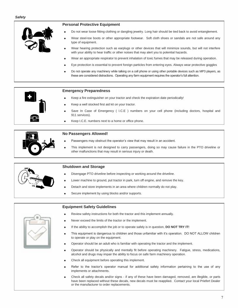
Equipment Safety Guidelines
Review safety instructions for both the tractor and this implement annually.
Never exceed the limits of the tractor or the implement.
If the ability to accomplish the job or to operate safely is in question, DO NOT TRY IT!
This equipment is dangerous to children and those unfamiliar with it’s operation. DO NOT ALLOW children
to operate or play on the equipment.
Operator should be an adult who is familiar with operating the tractor and the implement.
Operator should be physically and mentally fit before operating machinery. Fatigue, stress, medications,
alcohol and drugs may impair the ability to focus on safe farm machinery operation.
Check all equipment before operating this implement.
Refer to the tractor’s operator manual for additional safety information pertaining to the use of any
implements or attachments.
Check all safety decals and/or signs - if any of these have been damaged, removed, are illegible, or parts
have been replaced without these decals, new decals must be reapplied. Contact your local Priefert Dealer or the manufacturer to order replacements.
Shutdown and Storage
Disengage PTO driveline before inspecting or working around the driveline.
Lower machine to ground, put tractor in park, turn off engine, and remove the key.
Detach and store implements in an area where children normally do not play.
Secure implement by using blocks and/or supports.
No Passengers Allowed!
Passengers may obstruct the operator’s view that may result in an accident.
This implement is not designed to carry passengers, doing so may cause failure in the PTO driveline or
other malfunctions that may result in serious injury or death.
Emergency Preparedness
Keep a fire extinguisher on your tractor and check the expiration date periodically!
Keep a well stocked first aid kit on your tractor.
Save In Case of Emergency ( I.C.E ) numbers on your cell phone (including doctors, hospital and
911 services).
Keep I.C.E. numbers next to a home or office phone.
Personal Protective Equipment
Do not wear loose fitting clothing or dangling jewelry. Long hair should be tied back to avoid entanglement.
Wear steel-toe boots or other appropriate footwear. Soft cloth shoes or sandals are not safe around any
type of equipment.
Wear hearing protection such as earplugs or other devices that will minimize sounds, but will not interfere
with your ability to hear traffic or other noises that may alert you to potential hazards.
Wear an appropriate respirator to prevent inhalation of toxic fumes that may be released during operation.
Eye protection is essential to prevent foreign particles from entering eyes. Always wear protective goggles
Do not operate any machinery while talking on a cell phone or using other portable devices such as MP3 players, as
these are considered distractions. Operating any farm equipment requires the operator’s full attention.
Transportation
A high percentage of fatalities and injuries involve farm equipment on
roads and highways. It is very important to use common sense while
operating equipment and vehicles.
1. Plan your route.
2. Be aware of surface conditions, visibility, pedestrian and vehicular
traffic, curves, on-ramps and intersections.
3. Safest time to transport farm equipment on public roads is be-
tween sunrise and sunset.
4. Ensure that the hitches are properly secured and fastened.
5. Use the Slowing Moving Vehicle (SMV) emblem, if required by
your local and state laws, properly attached and visible.
Comply with state and local laws.
Perform a safety inspection on the tractor and correct any hazards
before you begin operating equipment.
Use approved lighting, flags, and necessary warning devices on
your farm equipment to alert other vehicles on the highway.
Inspect all warning lights and turn signals be sure these are
operational. If necessary you may need to purchase accessory
lighting devices that are available through your tractor dealership
or farm equipment store.
Use the safety devices that are installed on your tractor such as
ROPS, and seat belts. Never modify any safety device that has
been provided with your equipment.
Reduce speed if towed load is not equipped with brakes.
Keep the brake pedals locked together at all times and make sure
the brakes are properly adjusted.
20 MPH is the maximum transport speed for towed implements
without brake devices. DO NOT EXCEED.
If your tow weight is double the weight of the tractor do not exceed
10 mph.
If towed weight is more than double the weight of the tractor do
not operate the equipment; select a larger tractor.
Operator must have control of steering and braking at all times.
Slow down if your travel speed affects handling of farm equipment.
Slow down for turns and curves and avoid sudden uphill turns.
Sudden braking may cause loss of control over the implement.
Never travel at a speed which does not allow adequate control
of steering or lessens the ability to stop. Some rough terrain
may require a slower speed.
Maintenance and Your Safety
Read and understand the Operator’s Manual before performing any
maintenance. If you are unfamiliar with performing maintenance then
enlist someone with experience to assist you.
Wear appropriate protective clothing such as steel-toe boots, eye
protection, gloves, etc.
Work in a clean dry area.
Buildings should have adequate ventilation for the starting, run-
ning, and stopping of machinery while performing maintenance
and/or repairs.
Park the tractor and implement on level ground, disconnect the
PTO and remove the key.
Allow your equipment to cool completely.
Raise or lower the implement to the height needed to perform
maintenance or repairs. Blocks and/or jacks should be used to
prevent machinery from moving or falling.
Never attempt to grease or oil implement while in operation.
Perform routine maintenance regularly and in accordance with
the Operator Manual.
Inspect your implement before and after each use; any worn or
broken parts should be replaced immediately. Repair in accor-
dance with the Operator Manual.
Clean your implement after every use; and wipe away any excess
grease or oil that may have accumulated.
Check brakes, safety chains, blades, pins and clevis for wear,
breaks, missing parts or cracks.
Safety
8
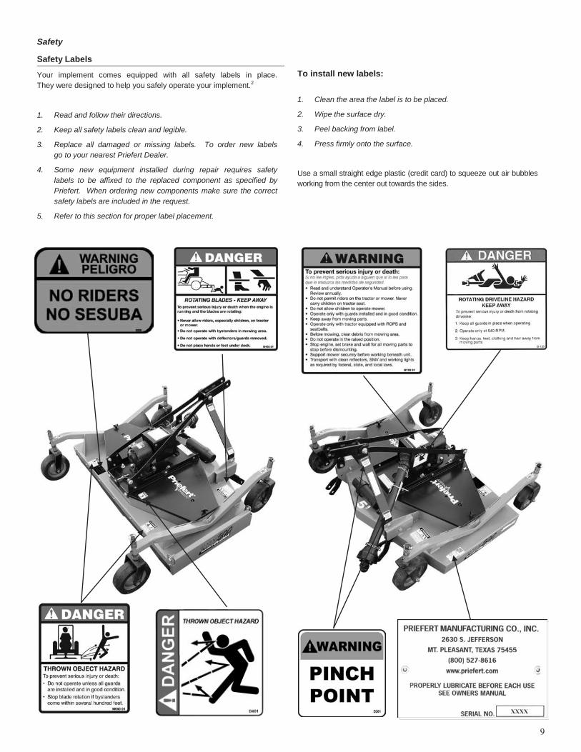
Safety Labels
Your implement comes equipped with all safety labels in place.
They were designed to help you safely operate your implement.2
1. Read and follow their directions.
2. Keep all safety labels clean and legible.
3. Replace all damaged or missing labels. To order new labels
go to your nearest Priefert Dealer.
4. Some new equipment installed during repair requires safety
labels to be affixed to the replaced component as specified by
Priefert. When ordering new components make sure the correct
safety labels are included in the request.
5. Refer to this section for proper label placement.
To install new labels:
1. Clean the area the label is to be placed.
2. Wipe the surface dry.
3. Peel backing from label.
4. Press firmly onto the surface.
Use a small straight edge plastic (credit card) to squeeze out air bubbles
working from the center out towards the sides.
Safety
9

Section 1: Set-Up Requirements
This unit is shipped completely assembled. Carefully follow instructions
for any final assembly. Hitch clevises and lock pins are sold separately.
Tractor Requirements
FMX models are designed with a 3-point category I hitch, which may be
adapted to a category II. Horse power rating of the tractor should not
exceed the PTO rating of the gearbox.
*May require the use of hitch bushings.
Three-Point Hitch
See Chart below for Tractor Categories and Three-Point Standards
The stabilizing arms are the 2-steel or cast arms that extend rearward
and provide the lift and are the pull-point for the implement (referred to
as lower link). The Upper Link is the 3rd mounting point and extends
from a top middle position at the rear of the tractor. Comparatively little
rearward force is applied from the top link.
The implement has been designed for front to back flotation while
moving on uneven terrain. Adjust the tractor’s top link to place the
upper hitch vertically above the lower lifting arms.
Tractor Hook-Up
1. If your tractor has a multi-speed PTO, be certain that the PTO is
set for 540 RPM.
2. Back tractor up to implement until lower 3-point links are aligned
with the hitch clevises on your implement. Always stop the
tractor, set the brake, shut off engine and remove the key before
dismounting from tractor.
3. Secure tractor’s 3-point lower links to the lower hitch clevises
using 7/8" hitch pins. Use appropriate hitch pins for your hitch
classification. Refer to ―Tractor Categories and Three-Point Hitch
Specification‖ table below.
4. Secure the tractor’s top link to the implement’s top hitch using a
3/4‖ hitch pin (supplied by customer). Adjust the tractor top link in
order to level the implement.
5. Start tractor engine and lift implement from the ground about
12-14 inches. Turn off the tractor.
6. Adjust the tractor’s 3-point hitch lift height so that the implement is
not lifted more than 14'' off the ground while the PTO Driveline is
attached to implement and tractor to avoid damaging the driveline.
7. Install the stabilizer arms, anti-sway blocks or chains, refer to your
tractor’s operating manual to limit side sway of hitch. Side to side
oscillation of about 2 inches is recommended.
8. Level the implement at the sides by adjusting the tractor lift links.
9. Measure the blade tip height on both sides, if these are not the
same refer to Section 2 ―Adjustments for Deck Mowing Height‖ on
page 16.
10. Mount the driveline to determine if this needs to be adjusted.
11. Carefully raise and lower the implement and ensure that tractor’s
tires, drawbars, and other equipment on the tractor do not come
into contact with the implement’s frame or PTO Driveline.
12. Use the lift control limiting stop on the tractor control lever to limit
the upward travel of the lever so the lift cannot be raised high
enough to cause contact between the drive shaft shield and front
shielding.
Model
Width
Hitch Type
Recommended Maximum HP
FMX500 5' I/ II* 40
FMX600 6' I/ II* 50
10
Tractor Categories and Three-Point Hitch Specifications3
Category
Hitch Pin Size Lower Hitch Spacing (Spread)
Horsepower Rating
Lower Link Upper Link
Inches Metric Inches Metric Inches Metric HP kW
I
3/4‖
19mm
7/8‖
22.4mm
26‖
718mm
Up to 45
Up to 35
II
1‖
25.5mm
1-1/8‖
28.7mm
32‖
870mm
Up to 100
Up to 75
III
1-1/4‖
31.75mm
1-7/16‖
37.4mm
38‖
1010mm
Up to 225
Up to 168

11
Driveline Installation
Refer to Figure 1-1
Your Finishing Mower driveline is connected with a push pin coupling to
the tractor and a pull collar attached to the gearbox on the implement.
To minimize torque on the driveline when starting up, remember to
always engage the PTO at a low engine RPM.
CAUTION
Tractor PTO shield and all implement guards must be in place
at all times during operation!
DANGER
Priefert advises against the use of PTO adapters as these
may defeat the purpose of the master shield on your tractor.
PTO adapters create an unguarded shaft area between the tractor and
the driveline guards that may cause entanglement that may result in
serious injury or death.
DANGER
Do not attempt to operate your PTO driveline while it is
unguarded as this may cause entanglement that can result in
serious injury or death.
IMPORTANT: If you are switching tractors or going to use a quick
connect hitch then you will need to check the driveline maximum and
minimum lengths to ensure the safe operation of your equipment. You
may find it necessary to use different drivelines.
NOTE: Before connecting the PTO Drivelines, clean and lubricate
driveline connection points. When checking PTO driveline minimum
length, it is important to have the tractor’s PTO driveline level with the
implement’s gearbox shaft. Engage the tractor’s hydraulic 3-point to
raise or lower the lower arms until the implement’s gearbox shaft is
level with the tractor’s PTO Shaft.
IMPORTANT: Before you begin the driveline adjustments, Priefert
strongly recommends that you request your dealer to fit your driveline
to your equipment. Priefert does not recommend modifications to our
products. If it is necessary to shorten the driveshaft, we recommend
that you contact your implement dealer for service.
PTO Driveline:
Refer to Figures 1-2 to determine minimum and maximum
operating lengths on page 11.
The PTO driveline minimum and maximum lengths must be checked
prior to initial use or when using a different tractor or adding a quick
connect hitch as well as to ensure that the driveline is compatible with
all work conditions required by your Priefert implement.
When fully extended the driveline must have a minimum overlap of the
inner and outer shafts of not less than 1/3 the free length with both
inner and outer shafts being of equal length or not less than a
6‖ (76mm) overlap.
Telescoping drivelines will have a variant in lengths due to changes in
the vertical angle of +20o due to uneven terrain or raising implement
for transport. It is very important not to operate your driveline with less
than the 1/3 free length or 6‖ (76mm) overlap as this may cause your
driveline to detach while in operation and pose a safety hazard to the
operator and possible damage to the tractor and implement.
1. Attach implement to your tractor.
2. Adjust tractor top link until the implement gearbox input shaft is
level with tractor input shaft.
3. Place tractor gear selector into park, turn engine off, set park
brake and remove key.
4. Securely block implement in this position.
5. Attach the PTO driveline to the implement’s shaft by sliding the
Push-Pin coupling of driveline over the splined input shaft of the
gearbox. Secure with driveline yoke locking device.
6. Slide the opposite driveline yoke end over the tractor’s splined
driveline shaft. Secure with driveline yoke locking device. The
driveline will require shortening if it is too long to fit between the
tractor and implement. Contact your Dealer to have the proper
adjustments made.
Determine your operating lengths:
1. Pull drive halves apart until fully extended, just before coming
apart. Record this measurement as A and subtract 6‖ (76mm)
and record as C measurement in your operator’s manual.
2. Push the driveline halves together. Record this measurement as
B and add 1‖ (25.4 mm) and record as D measurement in your
operator’s manual.
IMPORTANT: Never operate equipment with driveline extended
beyond measurement C. Never operate equipment with driveline
collapsed to less than measurement D.
Section 1: Set-Up Requirements
A. Push Pin Coupling Fig 1-1 — PTO Coupling (Safety chains not shown for clarity)
A
A

12
Dealer Instructions for Driveline Adjustment
Refer to Figures 1-2 for minimum and maximum lengths.
IMPORTANT: Adjusting the PTO Driveline requires that all cuts be
made equally to the inner/outer guards and the inner/outer shafts.
1. Remove the PTO driveline from the tractor’s splined output shaft
and the implement’s splined gearbox.
2. Pull the inner and outer shafts apart.
3. Remove the PTO shields (guarding).
4. Attach the implement’s inner cylinder to the implement’s gearbox
shaft.
5. Pull on the implement’s PTO driveline to ensure that it is securely
attached.
6. Attach the tractor’s output shaft to the tractor’s gearbox shaft.
7. Pull on the tractor’s PTO driveline to ensure that it is securely
attached.
8. Raise and lower implement to find the shortest operating distance
between the gearbox input shaft and tractor’s output shaft.
9. Hold both halves parallel to each other in the shortest operating
distance and mark them.
10. Measure the marks made in Step 9 and record them to shorten
the outer and inner guards equally.
11. Raise and lower implement to find the maximum operating
distance between the gearbox input shaft and tractor’s output
shaft.
12. Hold both halves parallel to each other in the maximum operating
distance and mark them.
13. Check that the driveline has a minimum of 6‖ (152.4mm) overlap
or 1/3 the total length of the driveline.
14. Measure the marks made in Step 13 and record them.
15. Disconnect the implement inner cylinder from the implement’s
gearbox shaft.
16. Disconnect the tractor’s output shaft from the tractor’s gearbox
shaft.
17. Securely clamp the implement driveline guard shield section in a
vise and cut off the guard at mark. File off any burrs. Repeat this
step for the tractor driveline guard shield. Use one of these
sections to create a cutting guide for the shaft and cylinder.
18. Use a padded vise to securely clamp the implement cylinder.
Do not over-tighten or damage the cylinder may occur.
19. Using the guard guide, mark the cylinder and cut. File any burrs and
clean off filings. Do not round the ends of the cylinder when filing.
20. Repeat steps 12 and 13 to shorten the tractor driveline shaft.
21. Apply grease to the inner shaft.
22. Reassemble the driveshaft, and securely attach the driveline
guard and reattach the PTO driveline to the tractor and
implement. Make sure that these are securely attached before
attempting to engage the PTO driveline.
23. The driveline should now be moved back and forth to insure that
both ends are secured to the tractor and implement. Reattach
any end that is loose.
24. Hook driveline safety chain in the hole in the inner driveline guard.
Attach the other end to the implement’s main frame.
25. Hook driveline safety chain in the hole in the outer driveline guard
and attach the other end to the tractor main frame.
26. Start tractor and raise implement just enough to remove blocks
used to support the implement frame.
27. Slowly engage tractor’s hydraulic 3-point to lower the implement.
Check for sufficient drawbar clearance. Move drawbar ahead,
aside or remove if required to eliminate binding.
28. Check to make certain that the driveline overall length does not
extend beyond the maximum recorded length as in Step 14.
CAUTION
Incorrectly fitted safety chains will result in excessive tension
causing the safety hook to open on the protection side. If this
occurs it is necessary to replace damaged hook with an original one.
This chain must be attached to the inner driveline shield and to the
implement to restrict shield rotation.
Measurements:
Section 1: Set-Up Requirements
Fig 1-2 — Checking Minimum and Maximum Lengths

Section 1: Set-Up Requirements
13
Gear Box Oil Requirements
Refer to Figure 1-4
Before putting your implement into service:
IMPORTANT:
Gearbox uses Multi-Purpose Gear Oil (ie: S.A.E. 80w/90 or
S.A.E. 85w/140 Multi-purpose gear oil.)
For all Grease Fittings use TYPE/Grade II tube grease.
Place implement so that the deck is secure and level.
Clean away any excess oil and dirt before removing 1/2‖ Pipe
Plug (located at top of gearbox and 1/8‖ pipe plug (located at
lower 1/3 of gearbox). Refer to figure 1-5 if your gearbox does
not have a fluid level plug as shown in Figure 1-4.
Fill gearbox until the oil level is even with the bottom opening of
the 1/8‖ pipe plug hole. *Refer to Figure 1-5 to check oil level if
your gearbox does not have the fluid level plug.
CAUTION:
DO NOT overfill gearbox!
This could cause damage to oil seals, and can cause
permanent damage to the gearbox.
This issue will not be covered under warranty.
Figure 1-4 — Gearbox without Fluid Level Plug
When filling you will need to visually check the oil level in the gearbox
through the fill opening. Fluid level should come half-way up the input
shaft as shown above; otherwise you may overfill the gearbox.

Section 2: Adjustments
Leveling Procedure
There are 4 primary adjustments that should be made prior to actual
field operations:
1. Deck leveling from left to right.
2. Tractor top link length.
3. Tractor lower link height.
Proper adjustment of each of these items will provide for higher
efficiency, improved cutting performance and longer blade life.
The following tools will be needed:
Pliable tape measure.
Spirit or carpenters level.
Open end or hex end wrench or socket set.
Protective gloves.
DANGER
Engage parking brake, disengage PTO, shut off tractor and
remove key before proceeding. Ensure that all moving parts
have come to a complete stop before dismounting the tractor.
Deck Leveling From Left to Right
Refer to Figure 2-1
1. Locate tractor with implement on a flat, level surface.
2. Use tractor’s hydraulic 3-point control lever to lower implement
until the tail-wheels make contact with the ground surface.
3. Place a level or another suitable leveling device on the front of the
implement’s deck as shown in Figure 2-1. Manually adjust either
one or both of the tractor’s lower 3-point arm height adjustments
to level the deck from left to right. Some tractors have only a
single adjusting crank.
Adjusting Center Point Top Length
This upper link needs to be adjusted to allow for the mower to ―float‖,
but still is able to lift the mower for transport or to avoid obstacles. This
adjustment is subjective; however, we recommend that the upper link
be adjusted out enough that when the mower is lifted above operating
level that the gauge wheels remain on the ground for a moment before
the 3-Point eventually raises the mower into the transport position. The
second set of adjustment holes on the upper pivot hitch should be used
when tractor’s center 3-point link is too short.
IMPORTANT: The blades should be positioned to cut material only at the
front of the implement. If deck is level or back of implement is lower than
the front, then the blades are subject to continuous material flow resulting
in additional blade wear, horsepower loss and frequent blade sharpening.
Gauge Wheel Height Adjustment
Refer to Figure 2-4
To adjust the mowing height the spacers must be suitably placed
above and/or below the axle bushings. Achieving the professional
appearance is by combining the spacers above or below the axle
bushings on all wheels.
The mowing height adjustment range for the Priefert Finishing Mower is
from a minimum of 1‖ to a maximum of 5". The adjustment spacers are
in 1/2" and 1" increments providing a broad range of height adjustment.
1. To set the minimum cutting height: place all the spacers above
the axel bushings.
2. To set the maximum cutting height: Place all spacers below the
axle bushings.
3. Using the tractor’s 3-point lift; raise the mower and securely lock
into position.
4. Holding gauge wheel and yoke assembly up, remove the locking
clevis pins from top of gauge wheel spindle. Squeeze both sides
of the clevis pin to unlock.
5. Position full-length spacers and half-length spacers as needed to
achieve the desired mowing height.
6. Lower mower to the ground.
7. Repeat steps 1-3 if needed. Make certain that all gauge wheels
are adjusted to the same height.
Wheel Interference Check
IMPORTANT: Do not operate mower until this interference check has
been performed. If you change tractors, you must perform the check for
that mounting.
1. Raise mower with tractor hydraulics to maximum height of
tractor lift.
2. Pivot both front gauge wheels forward and check that there is
clearance between gauge wheels and tractor tires.
3. If there is interference, you must move hitch pin to extended
position. Move tractor tires inward to obtain clearance or lower
mower until clearance exists. Set 3-Point quadrant stop so
mower cannot be raised beyond set point.
14
Figure 2-1 — Deck Leveling
Locking Clevis Pin
Axel Bushing
Spacers
Figure 2-4 — Gauge Wheel Height
15
Section 2: Adjustments
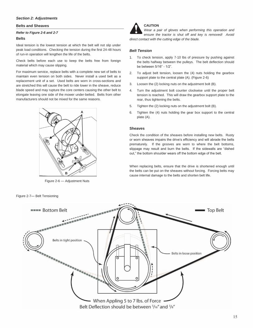
Belts and Sheaves
Refer to Figure 2-6 and 2-7
Belts
Ideal tension is the lowest tension at which the belt will not slip under
peak load conditions. Checking the tension during the first 24-48 hours
of run-in operation will lengthen the life of the belts.
Check belts before each use to keep the belts free from foreign
material which may cause slipping.
For maximum service, replace belts with a complete new set of belts to
maintain even tension on both sides. Never install a used belt as a
replacement unit of a set. Used belts are worn in cross-sections and
are stretched this will cause the belt to ride lower in the sheave, reduce
blade speed and may rupture the core centers causing the other belt to
elongate leaving one side of the mower under-belted. Belts from other
manufacturers should not be mixed for the same reasons.
CAUTION
Wear a pair of gloves when performing this operation and
ensure the tractor is shut off and key is removed! Avoid
direct contact with the cutting edge of the blade.
Belt Tension
1. To check tension, apply 7-10 lbs of pressure by pushing against
the belts halfway between the pulleys. The belt deflection should
be between 5/16‖ - 1/2‖.
2. To adjust belt tension, loosen the (4) nuts holding the gearbox
support plate to the central plate (A). (Figure 2-6)
3. Loosen the (2) locking nuts on the adjustment bolt (B).
4. Turn the adjustment bolt counter clockwise until the proper belt
tension is reached. This will draw the gearbox support plate to the
rear, thus tightening the belts.
5. Tighten the (2) locking nuts on the adjustment bolt (B).
6. Tighten the (4) nuts holding the gear box support to the central
plate (A).
Sheaves
Check the condition of the sheaves before installing new belts. Rusty
or worn sheaves impairs the drive’s efficiency and will abrade the belts
prematurely. If the grooves are worn to where the belt bottoms,
slippage may result and burn the belts. If the sidewalls are ―dished
out,‖ the bottom shoulder wears off the bottom edge of the belt.
When replacing belts, ensure that the drive is shortened enough until
the belts can be put on the sheaves without forcing. Forcing belts may
cause internal damage to the belts and shorten belt life.
Figure 2-7— Belt Tensioning
Figure 2-6 — Adjustment Nuts
A
B
16
Section 2: Adjustments
Using the Optional Side Chute
The FMX mowers provide the benefit of speed versus power &
performance by the use of an optional Side Chute. This Chute allows
the discharge of clippings from beneath the mower instead of mulching
the thatch within the mower deck.
During optimal conditions, operating the mower with the Side Chute
closed mulches the grass and discharges it behind the mower back into
the turf. Heavier or damper turf may require opening the chute door,
allowing the thatch to discharge from the side.
Opening the Side Chute door allows a variety of performance options.
With the door open to the first or second position, grass clippings will
fall into closer and tighter windrows for collection.
With the door open further, grass clippings are discharged rapidly,
allowing a faster cut and/or better performance in damper conditions
and with thicker, denser turfs. This reduces power loading during
operation in less than optimal conditions.
CAUTION
Operating mower with Side Chute Door open will increase the
possibility of thrown object hazards.
DANGER
Do not operate mower with side door removed. Operating
mower with side door removed greatly increases the risk of
thrown objects that can result in serious injury or death.
DANGER
Engage parking brake, disengage PTO, shut off tractor and
remove key before proceeding. Ensure that all moving parts
have come to a complete stop before dismounting the tractor.
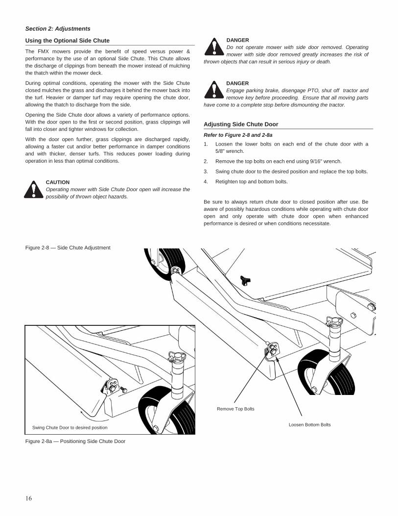
Adjusting Side Chute Door
Refer to Figure 2-8 and 2-8a
1. Loosen the lower bolts on each end of the chute door with a
5/8" wrench.
2. Remove the top bolts on each end using 9/16" wrench.
3. Swing chute door to the desired position and replace the top bolts.
4. Retighten top and bottom bolts.
Be sure to always return chute door to closed position after use. Be
aware of possibly hazardous conditions while operating with chute door
open and only operate with chute door open when enhanced
performance is desired or when conditions necessitate.
Figure 2-8 — Side Chute Adjustment
Loosen Bottom Bolts
Remove Top Bolts
Swing Chute Door to desired position
Figure 2-8a — Positioning Side Chute Door
Section 3: Operating Instructions
17
Operating Check List
Hazard control and accident prevention are dependent upon the
awareness, concern, prudence and proper training involved in the
operation, transport, maintenance and storage of the implement.
Therefore, it is absolutely essential that no one operates the implement
without first having read, fully understood and become totally familiar
with the Operator’s manual. Make sure the operator has paid particular
attention to:
Safety, pages 6-9
Section 1: Set-Up Requirements, pages 10-13
Section 2: Adjustments, pages 14-16
Section 3: Operating instructions, pages 17-20
Also make sure the operator has completed the Operating Checklist
below before using your implement:
Read and follow the ―Safety‖ section starting on page 6 carefully.
Read all of the ―Operating Instructions‖ in this section
Review your tractor’s operating instructions.
Check the implement initially and periodically for loose bolts & pins
and tighten if needed.
Make sure all guards and shields are in place.
Know your controls and how to stop tractor, engine and PTO
quickly in an emergency.
IMPORTANT: Priefert strongly recommends that no children are allowed
to operate the rotary implement.
Inspection Procedures
Make the following inspections with implement attached to a tractor and
PTO disengaged and completely stopped.
1. Inspect tractor safety equipment to make sure it is in good working
condition.
2. Carefully raise and lower implement to ensure that the drawbar,
tires, and other equipment on the tractor do not contact
implement’s frame or PTO driveline.
3. Check that all hardware is properly installed.
4. With implement deck resting on solid supports, PTO disengaged
and completely stopped, check that the blades are sharp and
secure and properly positioned.
5. Check PTO guards to make certain they are in good working
condition and in place.
6. Remove solid supports from under the deck and verify implement’s
front to rear and top link alignments.
7. Check that implement is level side-to-side and verify implement’s
deck is set to the correct height. See ―Leveling Procedure‖ on
page 14.
8. Lubricate all grease fitting locations. Make sure PTO shaft slip
joint is lubricated.
9. Check to be sure gear lube runs out the small check plug on the
gearbox.
10. Make sure that the driveline operates freely and is seated firmly in
the tractor PTO shaft spline groove.
11. Set tractor PTO and transmission into neutral before starting engine.
12. Set tractor PTO select lever to 540 RPM.
13. The remaining inspections are made by engaging the PTO to
check for vibrations.
IMPORTANT: Stop PTO immediately if vibration continues after a few
revolutions during start-up and anytime it occurs thereafter. Wait for
PTO to come to a complete stop before dismounting from tractor.
Make necessary repairs and adjustments before continuing on.
Start tractor, set throttle to idle or slightly above idle and slowly
engage PTO. Initial start-up vibration is normal and should stop
after a few revolutions. Stop PTO rotation immediately if vibration
continues.
Once the implement is running smoothly, increase tractor throttle
to operating RPM. Stop PTO immediately if vibration occurs.
IMPORTANT: Do not exceed RPM rating. Excessive engine speed will
cause damage to the power train components.
Transporting Procedures
CAUTION
When travelling on public roads at night or during the day,
use accessory lights and devices for adequate warning to
operators or other vehicles. Comply with federal, state, and local laws
IMPORTANT: Always disengage the tractor’s PTO before raising the
implement to transport position.
1. Make sure driveline does not contact tractor or implement when
raising implement to transport position. If it is necessary to lift
implement above 14‖; always disconnect the tractor PTO
driveline first.
2. Reduce tractor ground speed when turning, and allow enough
clearance so implement does not contact obstacles such as
buildings, trees or fences.
3. Limit transport speed to 20 mph. Transport only with a farm
tractor of sufficient size and horse power.
4. When traveling on roadways, transport in such a way that faster
moving vehicles may pass you safely.
5. Sudden braking can cause a towed load to swerve and upset.
Reduce speed if towed load is not equipped with brakes.
6. Shift tractor to a lower gear and use extra care when traveling
over rough terrain.
Section 3: Operating Instructions
Un-hooking the Implement
Unhook the implement from the tractor as follows:
1. Disengage power to the driveline.
2. Park the implement on a level solid hard surface.
3. Lower implement to level ground or onto stable support blocks.
4. Engage tractor park brake, shut tractor engine off and remove key
before dismounting from tractor.
5. Disconnect driveline from tractor PTO shaft.
6. Un-hook 3-point hitch from tractor.
7. Reinstall hitch pins, lynch pins and hairpin cotters in implement
hitch for storage.
8. Connect driveline safety chains together.
9. Rotate driveline and place driveline into the grooved storage
bracket.
Mowing Safety
DANGER
Do not engage tractor PTO while hooking-up and unhooking the
driveline or while someone is standing near the driveline. A person’s
body and/or clothing can become entangled in the driveline resulting in
serious injury or death.
Tractor PTO shield, gearbox shield, and driveline shield must be
secured in place while operating the implement to avoid injury or death
from entanglement in rotating drivelines.
Damaged drivelines can break apart while rotating at high speeds
causing serious injury or death. Always remove the implement from
service until damaged drivelines are repaired or replaced.
Implements have the ability to discharge objects at high speeds.
Therefore, the use of front & rear deck safety shields is strongly
recommended while mowing along highways or in an area where
people may be present!
Do not cut on steep inclines. The tractor and implement could flip over
causing damage to the equipment, bodily injury or death.
Never carry a passenger on the implement. A rider can fall and be run
over by the implement or tractor causing serious injury or death.
Do not use implement to lift or carry objects. Lifting and/or carrying
objects can result in damage to the implement, serious bodily injury or
death.
Never operate the implement while in the raised position. The
implement can discharge objects at high speeds resulting in serious
injury or death.
Do not use the deck as a working platform. The deck is not properly
designed or guarded for this use. Using the deck as a working platform
can cause serious injury or death.
Do not use deck as a fan. Cutting blades are not properly designed or
guarded for this use. Using the deck as a fan can result in injury or
death.
Do not use the driveline as a support or step.
Do not use the anti-rotation chain to support the driveline while it is
detached from the tractor. Use the grooved storage bracket on the
implement.
Do not allow anyone to stand between the tractor and the implement
during hookup. The Operator’s foot may slip off the clutch and back
over the assistant.
Do not operate machinery if you have consumed drugs or alcohol.
These will impair your judgment, alertness or coordination while
operating equipment. Seek medical advice if you are taking
prescription drugs before operating equipment.
Stay alert for hidden hazards, people, children entering into your work
area or traffic.
Do not leave the operator’s seat for ANY reason while the PTO
driveline is engaged and the tractor is running. Always disengage
PTO, engage parking brake, shut tractor engine off, remove switch key
and wait for blades to come to a complete stop before dismounting
from tractor.
18
Section 3: Operating Instructions
IMPORTANT: It is important to maintain correct PTO speed. Loss of PTO
speed will allow blades to hinge back and result in ragged, uneven cutting.
To reduce blade impact while striking obstacles; your rotary implement
is rigged with free swinging blades that will pivot or fold to absorb the
shock. However, it is best to ensure that the cutting height is adjusted
for the terrain in which you are mowing. This will extend the life of your
implement and will reduce premature blade wear or breakage.
Mowing should be avoided in extremely dry conditions as debris may
accumulate on your implement and may result in a fire due to heat
build-up caused by the friction of moving parts. In wet conditions
build-up of material on the underside of the implement will create a
loss of horsepower, increased wear and poor discharge and may
cause additional stress on the PTO driveline.
Know before you mow:
1. Check and mark potential hazards such as ditches, stumps, holes
or other obstacles that may cause the tractor to rollover or
damage the implement.
2. Inspect and clear the area for debris, and unseen foreign objects
such as branches, rocks, etc.
3. Develop a safe plan to avoid or minimize any safety hazards
found in steps 1 and 2.
4. Never assume the area is clear. Mow only in areas that you are
familiar with and are free of debris and unseen objects.
5. Extremely tall grass should be cut twice: first cut at the highest
possible cutting height to detect potential hazards, before cutting
at the desired cutting height.
IMPORTANT: Priefert strongly recommends that children should not
be allowed to operate this implement.
IMPORTANT: The PTO driveline while operating at 540 RPM is
actually rotating 9 times per second and at this speed the driveline can
pull clothing (for example) much faster than a human being can take
evasive action.
Note: Determining the correct ground speed depends upon two things:
The density of the material being cut and the size of the tractor
powering the implement.
Generally the quality of cut is better at lower ground speeds. Dense
ground cover will create the need to slow down even more. In certain
conditions the tractor tires will roll grass down resulting in uneven cut
when the grass fails to rebound. Should this happen you may try
reversing the direction of the cut and/or double cut to achieve the
desired finish.
General Operating Instructions
It is important that you familiarize yourself with the Operator’s
manual, A) completed the Operator’s Checklist, B) properly attached
implement to your tractor, C) made necessary leveling adjustments,
and D) preset your mowing height.
You will need to maintain 540 RPM speed and 2 to 4 mph ground
speed to produce a clean cut. Make a tractor gear and range
selection that will enable you to maintain these speed combinations.
If you need to go slower, reduce your tractor speed by down shifting
gears while maintaining the 540 RPM - do not reduce speed of the
PTO while operating as this will impact the quality of the cut.
Note: Do not allow the implement to drop violently on the ground.
Violent impacts would strongly stress all machine components and
could cause damage to your implement.
General Operating Procedures
Perform an operational safety check by starting the implement.
It is important that at any time during this safety check you detect a
malfunction in either the implement or tractor that you immediately
disengage the PTO, shut the tractor off, remove it’s key, and make
necessary repairs and/or adjustments before continuing on.
1. Start the tractor and set the engine throttle speed at low idle.
Raise the implement with the tractor’s rear hydraulic lift control
lever to transport position making sure that the PTO shaft does
not bind and does not contact the implement’s frame.
2. Lower the implement to the ground and at a low engine speed
engage the PTO. If everything is running smoothly at a low idle,
slowly raise the implement to transport height checking for bind
or chatter in the driveline.
3. Lower the implement to the ground and increase the tractor’s
engine RPM until it reaches 540 RPM.
4. If everything is still running smoothly, once more raise the
implement to transport height to check for driveline bind or chatter.
5. Lower the implement to the ground, return the engine to a low
idle, and disengage the PTO.
6. Position the adjustable stop on the tractor’s hydraulic lift lever so
the implement can be consistently returned to the same cutting
and transport height.
Avoid very low cutting heights especially on extremely uneven terrain.
Always cut downward on slopes and avoid crossing the face of the
steep slopes. Avoid sharp drops and cross diagonally through dips to
prevent hanging up the tractor and implement. Slow down in turns.
Remember to look back often.
DANGER
Keep hands and feet out! Do not step on or climb over the unit
while machine is in operation, or engine is running.
WARNING
Always disengage PTO, set parking brake, shut tractor off,
remove switch key and wait for blades to come to a complete
stop before dismounting from tractor.
CAUTION
Do not exceed rated mowing capacity of your implement! See
Specifications & Capacities for your model on pages 24-27 for
specified mowing Capacity. Using this implement for any other
work can damage the drive components, cutter blades, and deck
components!
Do not over speed PTO or machine damage may result. This
implement is designed to be used only with a tractor having a 540
RPM rear PTO.
19
WARNING
A heavy load can cause instability in driving a tractor. Make
sure the front of the tractor is properly counter-balanced with
weights. An unstable tractor could steer badly and possibly tip over,
causing injury or death.
Transporting Instructions
On roadways transport in such a manner that faster moving vehicles
can easily see you and pass you safely. Reduce your speed when
traveling over rough and hilly terrain. Avoid quick or sharp steering
corrections. Take extra care to insure that the implement doesn’t come
into contact with obstacles such as trees, buildings or fences.
Use accessory lights and appropriate reflective devices to provide
adequate warning to pedestrians and other vehicle operators when
traveling on public roads and in the dark of night. Comply with all local,
state and federal laws.
It is important that you inspect the area where you will be mowing and
clear it of safety hazards and foreign objects either before or after you
arrive at the mowing site. Never assume the area is clear. Mow only in
areas that you are familiar with and are free of debris and unseen
objects.
Use your 3-point hitch or Quick-Hitch to lift your implement into
transport position while making tight turns and to reverse direction.
Now that you are prepared and well briefed you may begin
mowing.
Note: When crossing ditches with steep inclines or going up sharp
inclines, it is probable that the main driveline inner profile will penetrate
into the outer housing to its maximum depth until the assembly
becomes solid. This type of abusive operation can result in serious
damage to the tractor and implement by driving the PTO into the tractor
and through the support bearings or downward onto the PTO shaft
causing it to break apart.
Warning
Many varied objects, such as wire, cable, rope or chains, may
become entangled in the operating parts of the implement.
These could then swing at greater velocities than the blades thus
creating a hazard that could result in serious injury or death. Never
allow the cutting blades to contact such items.
Mowing Instructions
1. Ensure the tractor’s park brake is engaged, the PTO is
disengaged, and the implement is resting on the ground.
2. Start your implement slowly; do not use full throttle. Allow 10 to
15 seconds for implement blades to become aligned properly
before going to 540 RPM.
3. Maintain 540 RPM PTO speed while mowing. Loss of PTO speed
will allow the blades to pivot or fold back and result in ragged,
uneven cutting.
4. Travel only as fast as the tractor is capable of making smooth
even cuts without overloading the tractor.
5. Mow 45 to 50 feet, stop and check to see that the implement is
adjusted properly.
6. Do not engage PTO while implement is in the fully raised position.
7. Periodically disengage the PTO, turn off the tractor, remove the
ignition key and check for foreign objects wrapped around the
rotor shaft. Block implement’s deck up before removing objects.
8. Frequently inspect the implement for loose bolts and nuts.
Tighten all loose bolts and nuts.
9. Always work at a safe distance from roads, populated areas or
places.
10. Be alert for people, children, pets or livestock entering your work
area while operating your implement.
In the event you do strike an object; immediately disengage the PTO
driveline, stop the tractor, set the brake, remove the key and inspect
the tractor and implement. Make necessary repairs to the implement or
tractor before resuming operation.
Taking a Break:
Do not operate any machinery if you are exhausted. Whether you are
done mowing, need to take a break, or just need to make a few
adjustments to the implement, remember to perform the following shut
down procedures:
To shut down the implement:
1. Reduce the tractor’s engine RPM.
2. Disengage the PTO.
3. Stop on level ground.
4. Bring tractor to a complete stop.
5. Set the park brake.
6. Lower the implement to the ground.
7. Turn off the engine and remove the key.
8. Stay on the tractor until the blades come to a complete stop.
Section 3: Operating Instructions
20
21
Section 4: Maintenance
Servicing
Proper servicing and adjustment is the key to the long life of any
implement. With careful inspection and routine maintenance, you can
avoid costly down time and repair. Do not get under the machine to
make measurements or adjustments without securely blocking
implement first.
DANGER
Always disconnect main driveline from tractor PTO before
servicing the underside of the implement’s deck. Implement
can be engaged if tractor is started resulting in damage to the
implement, bodily injury and/or death.
WARNING
Always secure implement’s deck in the up position with solid
supports before servicing the underside of the implement.
Never work under equipment supported by hydraulics. Hydraulics can
drop equipment if controls are actuated or if hydraulic lines burst.
Either situations can drop the implement instantly even when power to
the hydraulics is shut off.
General Maintenance
1. Check all bolts after each use.
2. Replace any worn, damaged or illegible safety labels by obtaining
new labels from your Priefert Dealer. If you are operating your
implement in a heavy duty capacity then maintenance operations
may need to be performed more frequently.
3. Before you add oil to the gearbox, it is important that the fill plug
area be wiped clean before removing plugs. Debris mixed into the
lubricants will rapidly wear the parts and destroy bearings and
gears. Oil levels must be checked when implement is on a level
surface.
Maintenance Schedule
Every 8 Hours of Service:
Grease the support of the spindle.
Grease the ―U‖ joints (2) of the PTO driveline.
Check the bolts that connect the blades to the spindle.
Grease wheel axles (4) and axle bushings (4)
Every 50 Hours of Service:
Change the first oil fill in the gearbox after the initial 50 hours of
service. After this point, oil should be changed after every 250
hours of service.
Check blades for wear or damage. Replace if necessary. Never
try to straighten a bent blade.
Disconnect and clean the PTO driveline. Cover the sliding parts
with grease before reassembling.
Every 250 Hours of Service:
Change oil in the gearbox.
Blade Maintenance
CAUTION
Use heavy leather gloves when inspecting, sharpening or
replacing blades.
Always inspect implement blades before each use. Make certain these
are properly installed and are in good working condition. Use only
original blades on the implement as they are made of a special heat-
treated alloy steel. Substituting blades from other manufacturers may
not meet our specifications and may create a hazardous situation if
these fail.
Replace any blade that is damaged, worn, bent or excessively nicked.
Never try to straighten a bent blade! Small nicks can be ground out
when sharpening.
Blade Sharpening
Blades should be sharpened at both cutting edges at the same angle
as the original cutting edge. Do not sharpen blade to a razor edge, but
leave a 1/32‖ blunt edge. Balance each blade after sharpening
Care should be taken in order not to remove any more material
than necessary to sharpen blade.
Blade Replacement
Blade bolts are right-handed bolts.
1. Always install blade cutting edge facing direction of rotation.
2. Remove the bolt counter-clockwise and blade washer from the
bottom of the blade to be replaced. Remove blade.
3. Inspect bolts and nuts threads to ensure that these are not worn
or damaged. Replace worn or damaged bolts and nuts.
4. Install the blade washer into the center hole on blade.
5. Replace the bolt and tighten clockwise.
IMPORTANT: Not replacing both blades will result in an out-of-balance
condition that will contribute to premature bearing wear.
Shear Bolt Replacement
1. Slide the yoke shield back.
2. Remove damaged shear bolt and nut with a hammer and punch.
3. Replace damaged or lost shear bolt by realigning the holes in
yoke and shaft.
4. Install new shear bolt and secure with nut.
5. Secure yoke shield by locking back into place.
Blade Spindle Maintenance
Blade spindles should be lubricated after every 8 hours of operation.
Our mowers provide easy access to the spindles via holes on outer
shield. When lubricating the spindle allow for a small amount of excess
grease to vent through top seal.
Note: Do not over lubricate the spindles as excess grease may
damage belt drive.
Section 4: Maintenance
Driveline Maintenance
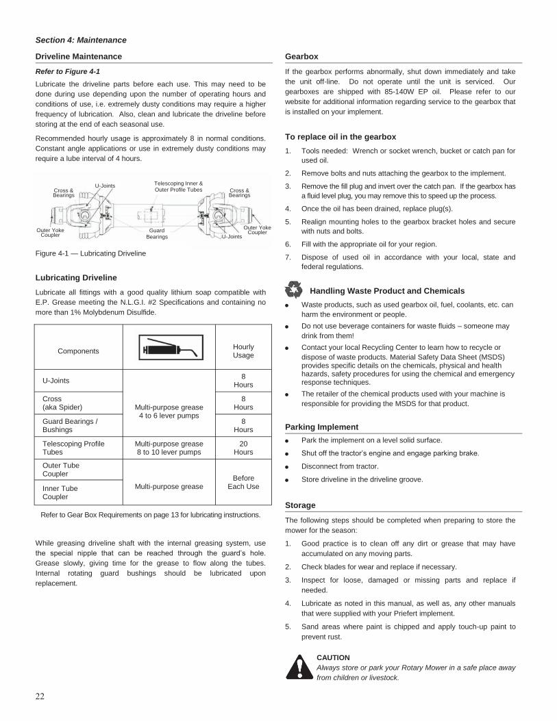
Refer to Figure 4-1
Lubricate the driveline parts before each use. This may need to be
done during use depending upon the number of operating hours and
conditions of use, i.e. extremely dusty conditions may require a higher
frequency of lubrication. Also, clean and lubricate the driveline before
storing at the end of each seasonal use.
Recommended hourly usage is approximately 8 in normal conditions.
Constant angle applications or use in extremely dusty conditions may
require a lube interval of 4 hours.
Lubricating Driveline
Lubricate all fittings with a good quality lithium soap compatible with
E.P. Grease meeting the N.L.G.I. #2 Specifications and containing no
more than 1% Molybdenum Disulfide.
Refer to Gear Box Requirements on page 13 for lubricating instructions.
While greasing driveline shaft with the internal greasing system, use
the special nipple that can be reached through the guard’s hole.
Grease slowly, giving time for the grease to flow along the tubes.
Internal rotating guard bushings should be lubricated upon
replacement.
Gearbox
If the gearbox performs abnormally, shut down immediately and take
the unit off-line. Do not operate until the unit is serviced. Our
gearboxes are shipped with 85-140W EP oil. Please refer to our
website for additional information regarding service to the gearbox that
is installed on your implement.
To replace oil in the gearbox
1. Tools needed: Wrench or socket wrench, bucket or catch pan for
used oil.
2. Remove bolts and nuts attaching the gearbox to the implement.
3. Remove the fill plug and invert over the catch pan. If the gearbox has
a fluid level plug, you may remove this to speed up the process.
4. Once the oil has been drained, replace plug(s).
5. Realign mounting holes to the gearbox bracket holes and secure
with nuts and bolts.
6. Fill with the appropriate oil for your region.
7. Dispose of used oil in accordance with your local, state and
federal regulations.
Handling Waste Product and Chemicals
Waste products, such as used gearbox oil, fuel, coolants, etc. can
harm the environment or people.
Do not use beverage containers for waste fluids – someone may
drink from them!
Contact your local Recycling Center to learn how to recycle or
dispose of waste products. Material Safety Data Sheet (MSDS) provides specific details on the chemicals, physical and health hazards, safety procedures for using the chemical and emergency response techniques.
The retailer of the chemical products used with your machine is
responsible for providing the MSDS for that product.
Parking Implement
Park the implement on a level solid surface.
Shut off the tractor’s engine and engage parking brake.
Disconnect from tractor.
Store driveline in the driveline groove.
Storage
The following steps should be completed when preparing to store the
mower for the season:
1. Good practice is to clean off any dirt or grease that may have
accumulated on any moving parts.
2. Check blades for wear and replace if necessary.
3. Inspect for loose, damaged or missing parts and replace if
needed.
4. Lubricate as noted in this manual, as well as, any other manuals
that were supplied with your Priefert implement.
5. Sand areas where paint is chipped and apply touch-up paint to
prevent rust.
CAUTION
Always store or park your Rotary Mower in a safe place away
from children or livestock.
22
Components
Hourly Usage
U-Joints
Multi-purpose grease 4 to 6 lever pumps
8 Hours
Cross (aka Spider)
8 Hours
Guard Bearings / Bushings
8 Hours
Telescoping Profile Tubes
Multi-purpose grease 8 to 10 lever pumps
20 Hours
Outer Tube Coupler
Before Each Use
Multi-purpose grease Inner Tube
Coupler
U-Joints Telescoping Inner & Outer Profile Tubes
Guard Bearings
Cross & Bearings
Cross & Bearings
U-Joints Outer Yoke
Coupler
Outer Yoke Coupler
Figure 4-1 — Lubricating Driveline
23
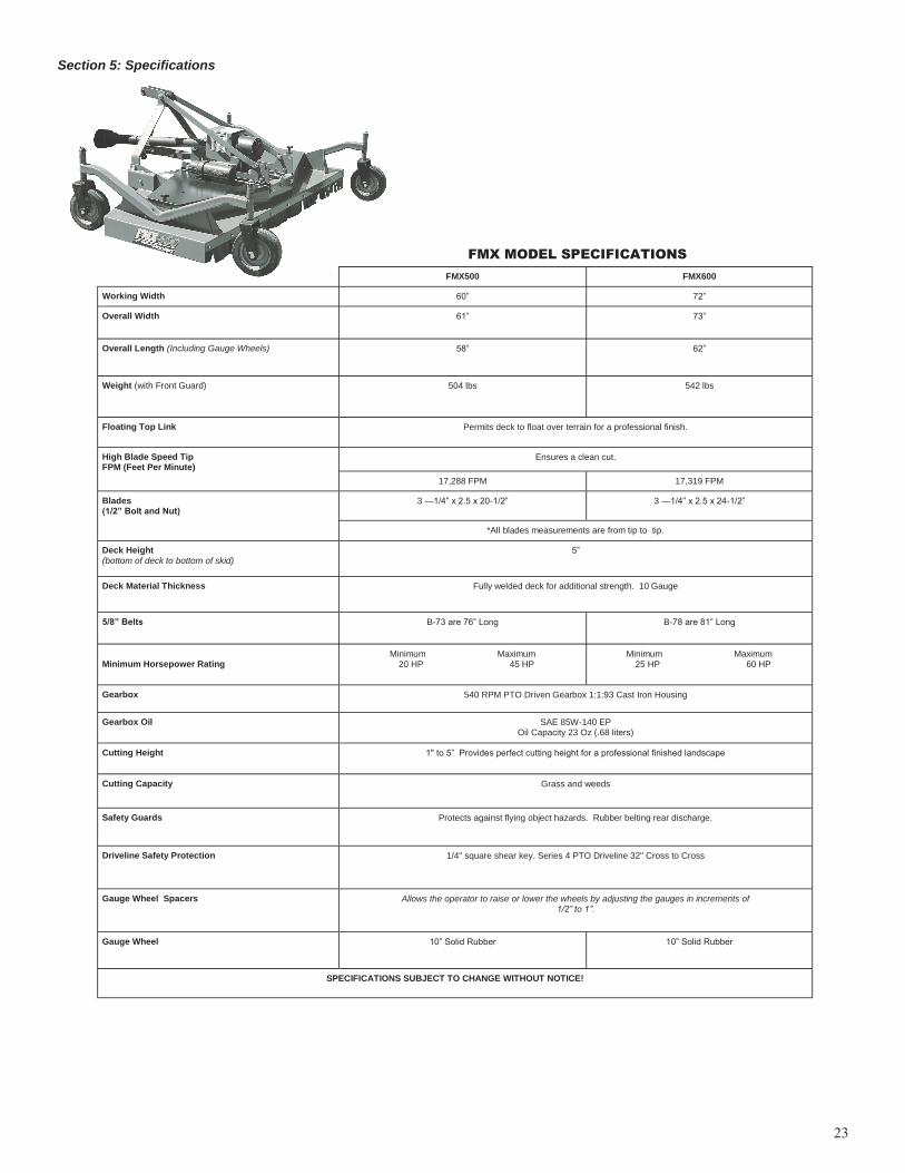
FMX500 FMX600
Working Width 60‖ 72‖
Overall Width 61‖ 73‖
Overall Length (Including Gauge Wheels) 58‖ 62‖
Weight (with Front Guard) 504 lbs 542 lbs
Floating Top Link Permits deck to float over terrain for a professional finish.
High Blade Speed Tip FPM (Feet Per Minute)
Ensures a clean cut.
17,288 FPM 17,319 FPM
Blades (1/2” Bolt and Nut)
3 —1/4‖ x 2.5 x 20-1/2‖ 3 —1/4‖ x 2.5 x 24-1/2‖
*All blades measurements are from tip to tip.
Deck Height
(bottom of deck to bottom of skid) 5‖
Deck Material Thickness Fully welded deck for additional strength. 10 Gauge
5/8” Belts B-73 are 76‖ Long B-78 are 81‖ Long
Minimum Horsepower Rating
Minimum Maximum 20 HP 45 HP
Minimum Maximum 25 HP 60 HP
Gearbox 540 RPM PTO Driven Gearbox 1:1:93 Cast Iron Housing
Gearbox Oil SAE 85W-140 EP Oil Capacity 23 Oz (.68 liters)
Cutting Height 1" to 5‖ Provides perfect cutting height for a professional finished landscape
Cutting Capacity Grass and weeds
Safety Guards Protects against flying object hazards. Rubber belting rear discharge.
Driveline Safety Protection 1/4" square shear key. Series 4 PTO Driveline 32" Cross to Cross
Gauge Wheel Spacers Allows the operator to raise or lower the wheels by adjusting the gauges in increments of 1/2” to 1”.
Gauge Wheel 10‖ Solid Rubber 10‖ Solid Rubber
SPECIFICATIONS SUBJECT TO CHANGE WITHOUT NOTICE!
FMX MODEL SPECIFICATIONS
Section 5: Specifications
24
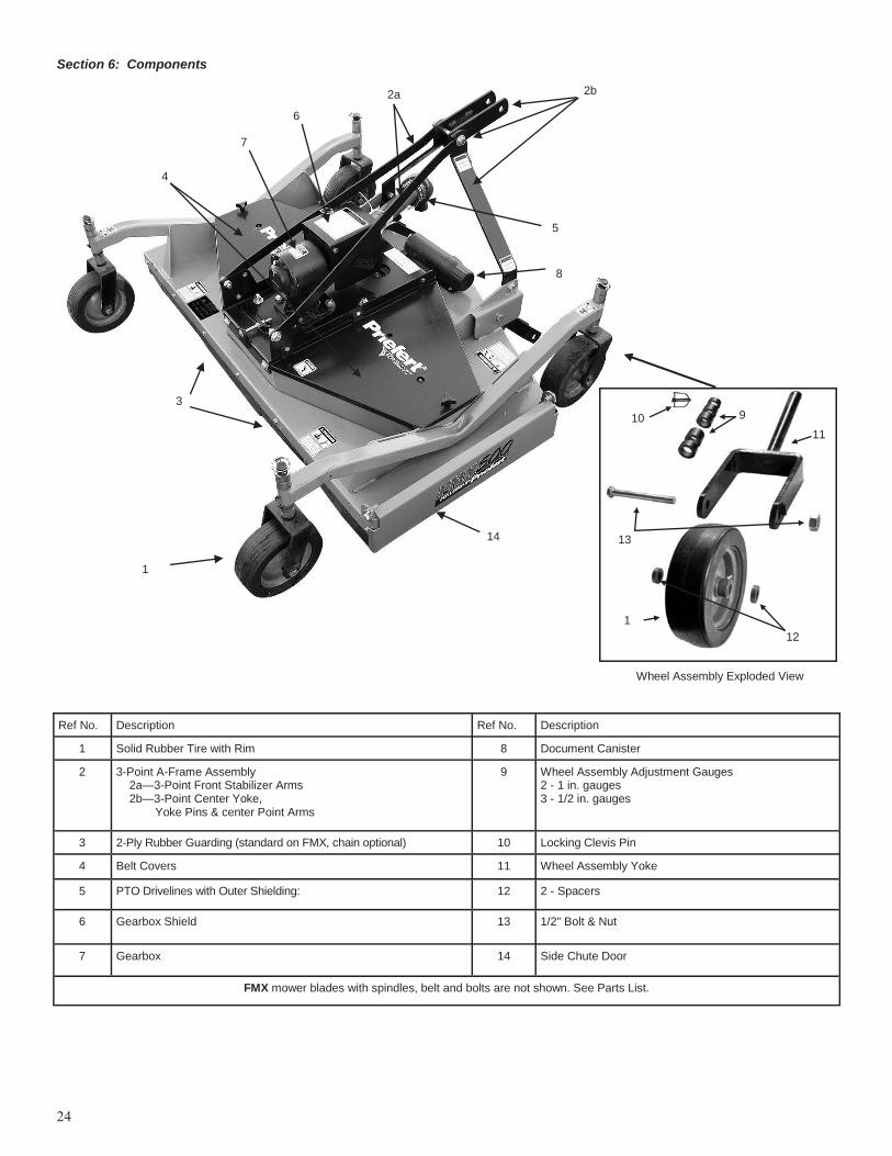
Section 6: Components
8
3
2a 2b
Ref No. Description Ref No. Description
1 Solid Rubber Tire with Rim 8 Document Canister
2 3-Point A-Frame Assembly 2a—3-Point Front Stabilizer Arms 2b—3-Point Center Yoke, Yoke Pins & center Point Arms
9 Wheel Assembly Adjustment Gauges 2 - 1 in. gauges 3 - 1/2 in. gauges
3 2-Ply Rubber Guarding (standard on FMX, chain optional) 10 Locking Clevis Pin
4 Belt Covers 11 Wheel Assembly Yoke
5 PTO Drivelines with Outer Shielding: 12 2 - Spacers
6 Gearbox Shield 13 1/2" Bolt & Nut
7 Gearbox 14 Side Chute Door
FMX mower blades with spindles, belt and bolts are not shown. See Parts List.
9
1
Wheel Assembly Exploded View
10
11
12
13
1
4
5
6
7
14
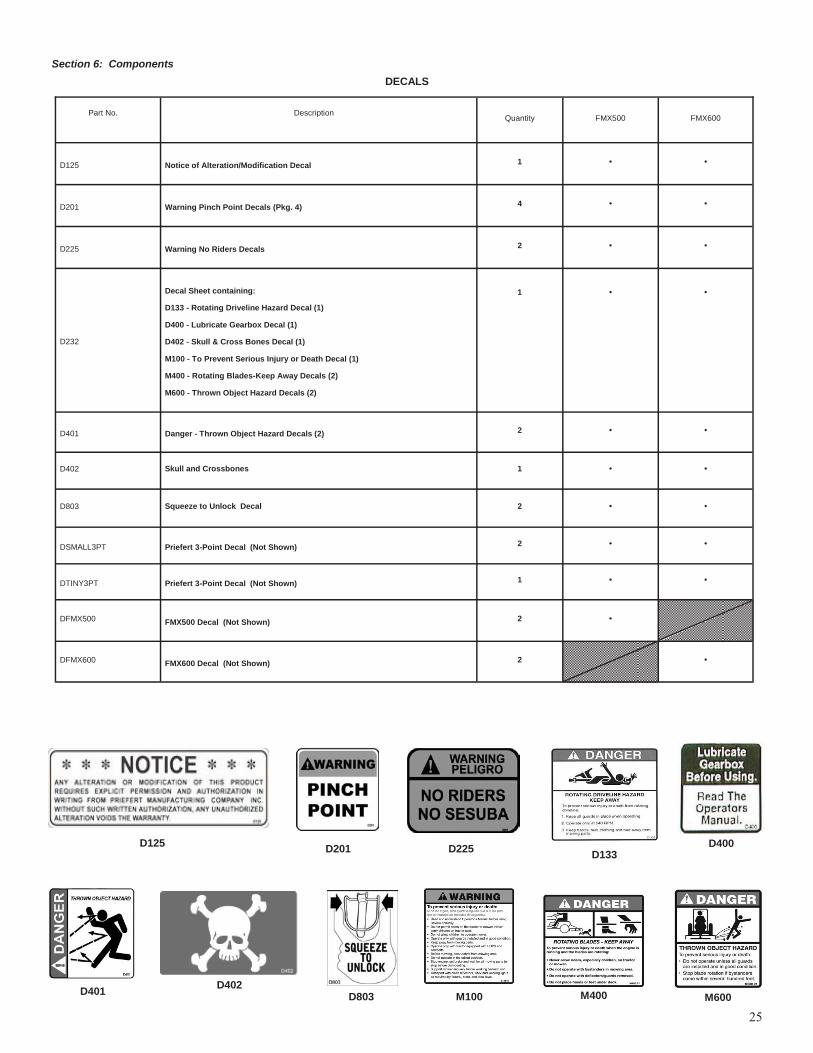
Part No.
Description
Quantity FMX500 FMX600
D125 Notice of Alteration/Modification Decal 1 • •
D201 Warning Pinch Point Decals (Pkg. 4) 4 • •
D225 Warning No Riders Decals 2 • •
D232
Decal Sheet containing:
D133 - Rotating Driveline Hazard Decal (1)
D400 - Lubricate Gearbox Decal (1)
D402 - Skull & Cross Bones Decal (1)
M100 - To Prevent Serious Injury or Death Decal (1)
M400 - Rotating Blades-Keep Away Decals (2)
M600 - Thrown Object Hazard Decals (2)
1
•
•
D401 Danger - Thrown Object Hazard Decals (2) 2 • •
D402 Skull and Crossbones 1 • •
D803 Squeeze to Unlock Decal 2 • •
DSMALL3PT Priefert 3-Point Decal (Not Shown) 2 • •
DTINY3PT Priefert 3-Point Decal (Not Shown) 1 • •
DFMX500 FMX500 Decal (Not Shown) 2 •
DFMX600 FMX600 Decal (Not Shown) 2 •
DECALS
D125 D201 D225
M600 M400 M100
D133
D401
D400
D402
25
Section 6: Components
D803
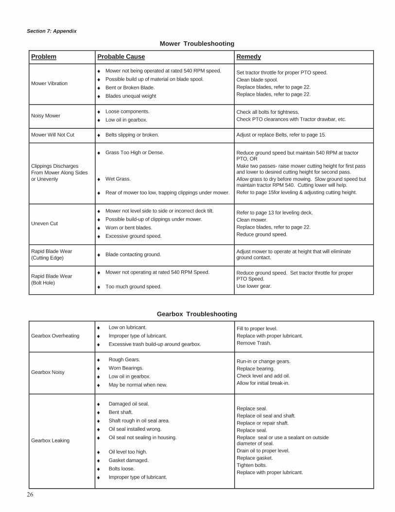
Section 7: Appendix
Mower Troubleshooting
Problem Probable Cause Remedy
Mower Vibration
Mower not being operated at rated 540 RPM speed.
Possible build up of material on blade spool.
Bent or Broken Blade.
Blades unequal weight
Set tractor throttle for proper PTO speed.
Clean blade spool.
Replace blades, refer to page 22.
Replace blades, refer to page 22.
Noisy Mower Loose components.
Low oil in gearbox.
Check all bolts for tightness.
Check PTO clearances with Tractor drawbar, etc.
Mower Will Not Cut Belts slipping or broken. Adjust or replace Belts, refer to page 15.
Clippings Discharges
From Mower Along Sides
or Unevenly
Grass Too High or Dense.
Wet Grass.
Rear of mower too low, trapping clippings under mower.
Reduce ground speed but maintain 540 RPM at tractor PTO, OR
Make two passes- raise mower cutting height for first pass and lower to desired cutting height for second pass.
Allow grass to dry before mowing. Slow ground speed but maintain tractor RPM 540. Cutting lower will help.
Refer to page 15for leveling & adjusting cutting height.
Uneven Cut
Mower not level side to side or incorrect deck tilt.
Possible build-up of clippings under mower.
Worn or bent blades.
Excessive ground speed.
Refer to page 13 for leveling deck.
Clean mower.
Replace blades, refer to page 22.
Reduce ground speed.
Rapid Blade Wear
(Cutting Edge) Blade contacting ground.
Adjust mower to operate at height that will eliminate ground contact.
Rapid Blade Wear
(Bolt Hole)
Mower not operating at rated 540 RPM Speed.
Too much ground speed.
Reduce ground speed. Set tractor throttle for proper PTO Speed.
Use lower gear.
Gearbox Troubleshooting
Gearbox Overheating
Low on lubricant.
Improper type of lubricant.
Excessive trash build-up around gearbox.
Fill to proper level.
Replace with proper lubricant.
Remove Trash.
Gearbox Noisy
Rough Gears.
Worn Bearings.
Low oil in gearbox.
May be normal when new.
Run-in or change gears.
Replace bearing.
Check level and add oil.
Allow for initial break-in.
Gearbox Leaking
Damaged oil seal.
Bent shaft.
Shaft rough in oil seal area.
Oil seal installed wrong.
Oil seal not sealing in housing.
Oil level too high.
Gasket damaged.
Bolts loose.
Improper type of lubricant.
Replace seal.
Replace oil seal and shaft.
Replace or repair shaft.
Replace seal.
Replace seal or use a sealant on outside diameter of seal.
Drain oil to proper level.
Replace gasket.
Tighten bolts.
Replace with proper lubricant.
26
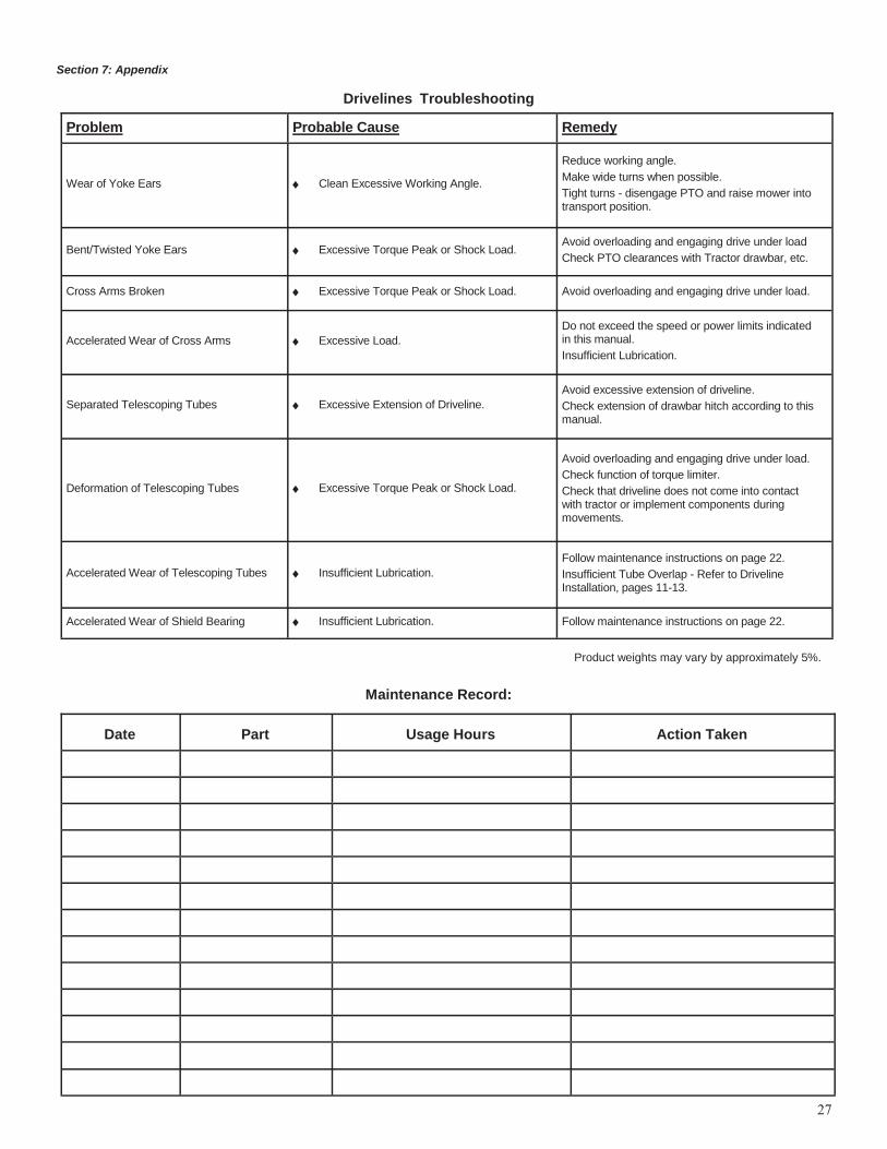
27
Problem Probable Cause Remedy
Wear of Yoke Ears Clean Excessive Working Angle.
Reduce working angle.
Make wide turns when possible.
Tight turns - disengage PTO and raise mower into transport position.
Bent/Twisted Yoke Ears Excessive Torque Peak or Shock Load. Avoid overloading and engaging drive under load
Check PTO clearances with Tractor drawbar, etc.
Cross Arms Broken Excessive Torque Peak or Shock Load. Avoid overloading and engaging drive under load.
Accelerated Wear of Cross Arms Excessive Load.
Do not exceed the speed or power limits indicated in this manual.
Insufficient Lubrication.
Separated Telescoping Tubes Excessive Extension of Driveline.
Avoid excessive extension of driveline.
Check extension of drawbar hitch according to this manual.
Deformation of Telescoping Tubes Excessive Torque Peak or Shock Load.
Avoid overloading and engaging drive under load.
Check function of torque limiter.
Check that driveline does not come into contact with tractor or implement components during movements.
Accelerated Wear of Telescoping Tubes Insufficient Lubrication.
Follow maintenance instructions on page 22.
Insufficient Tube Overlap - Refer to Driveline Installation, pages 11-13.
Accelerated Wear of Shield Bearing Insufficient Lubrication. Follow maintenance instructions on page 22.
Product weights may vary by approximately 5%.
Drivelines Troubleshooting
Section 7: Appendix
Maintenance Record:
Date Part Usage Hours Action Taken

Limited Warranties: Priefert Manufacturing Company, Inc., (“Priefert”) 2630 South Jefferson, P.O. Box 1540, Mount Pleasant, TX 75456-1540, warrants for one (1) year from the purchase date to the original non-commercial, governmental, or municipal purchaser (“Purchaser”) and warrants for six (6) months to the original commercial or industrial purchaser (“Purchaser”) that the product purchased are free from defects in material or workmanship. Priefert will replace or repair, free of charge to the original purchaser any part(s) found, upon examination at our factory, to be defective under normal use and service due to defects in material or workmanship, provided that the original purchaser: a. Notifies Priefert in writing of any defect in material or workmanship within the above specified warranty period. b. Returns must be routed through an authorized Priefert dealer or distributor from whom the purchase was made. c. Purchaser is responsible for cost of shipping. In no event will Priefert be held liable under this warranty unless written notice is received and failure must have occurred within the warranty period. Genuine Priefert replacement parts and components will be warranted for 90 days from date of purchase, or the remainder of the original equipment warranty period, whichever is longer. This limited warranty does not apply to any part of the product which has been subjected to improper or misintended use, negli-gence, alteration, modification, or accident, damaged due to lack of maintenance or use of wrong oil or lubricants, or repairs that have been made with parts other than those obtainable through Priefert, or which has served its usual life. This limited warranty does not apply to any expendable item such as blades, shields, guards, or pneumatic tires, or other trade accessories since these items are warranted separately by their respective manufacturers, except as specifically noted in your Operator’s Manual. Except as provided herein, no employee, agent, Dealer, or other person is authorized to give any warranties of any nature on behalf of Priefert. Only Priefert is authorized to make any representation to the purchaser concerning “normal” use and service for its product as described in the Operator’s Manual, or in authorized printed materials or stickers affixed to the product. If after examination of the product and/or part(s) in question; Priefert finds them to be defective under normal use and service due to defects in material or workmanship,
Priefert will:
1. Repair or replace the defective product or part(s); if Priefert has made several reasonable number of attempts in repairing the
product and/or part(s) to conform to the warranty; then 2. Priefert will replace part(s) or product. 3. Purchaser is responsible for any labor charges exceeding a reasonable amount as determined by Priefert and for returning
product and/or part(s) to the Dealer, whether or not the claim is approved. Purchaser is responsible for the transportation cost for the product or part(s) from the Dealer to the factory.
The choice of remedy shall belong to Priefert. Repair or replacement are the only remedies against Priefert under this limited warranty.
Limitation of Liability: 1. Priefert disclaims any express (except as set forth herein) and implied warranties with respect to the product including, but not
limited to, merchantability and fitness for a particular purpose. 2. Priefert makes no warranty as to the design, capability, capacity, or suitability for use of the product. 3. This warranty shall not be interpreted to render us liable for injury or damages of any kind or nature to person or property.
Priefert will not be liable for any special, incidental or consequential damages based upon breach of warranty, breach of contract, negligence, strict tort liability, or any other legal theory. Such damages include but are not limited to loss of crops, loss of savings or revenue, cost of capital, loss of use of equipment, facilities or services, down time, expense or loss incurred for labor, supplies, substitute machinery, rental, and claims of third parties including customers, and injury to property.
Supplementary: 1. Proper venue for any lawsuits arising from or related to this limited warranty shall be only in Titus County, Texas. 2. Priefert may waive compliance with any of the terms of this limited warranty, but no waiver of any terms shall be deemed to be
a waiver of any other term. 3. If any provision of this limited warranty violates any applicable law and is held unenforceable, then the invalidity of such
provision shall not invalidate any other provisions. 4. Applicable law may provide rights and benefits to purchaser in addition to those herein.
28

References
1.Sentry Insurance, FEMA, Owner’s and Operators Manuals for Farm Equipment, Sentry Insurance, Stevens Point, WI, revised Management Bulletin No. 112, 90-42; March 2007, pp S-2.
2. Sentry Insurance, FEMA, Safety Signs for Farm Equipment, Sentry Insurance, Stevens Point, WI, 90-34, October 2006, pgs 1-20.
3.American Society of Agricultural and Biological Engineers, ASABE, Three-Point Free-Link Attachment for Hitching Implements, ASAE S217.12 DEC2001 (ISO 730-1:1994) (R2007), Printed ASABE,
St. Joseph, MO. pgs 1-10.
4.International Standardization Organization (ISO), ISO 11684, Tractors, machinery for agriculture and forestry, powered lawn and garden equipment - Safety Signs and hazard pictorials - General
purpose, Printed in Switzerland, ISO 11684:1995(E),
5. International Standardization Organization (ISO), ISO 17101, Agricultural machinery - Rotary and Flail mowers - Thrown-object test and acceptance, Printed in Switzerland, ISO 17101:2004(E),
6. Occupational Safety and Health Administration (OSHA), Safety for Agricultural Equipment, 29 CFR 1928.57,
http://www.osha.gov/pls/oshaweb/owadisp.show_document?p_table=STANDARDS&p_id=10958.
7.Tractor and Machinery Association of Australia (TMA), OHS Guidelines For Agricultural Machinery, Maddock Lonie & Chisholm, Melbourne
Victoria, Australia, Fourth Edition, 2003, pgs 1-57.
Suggested References
Priefert assumes no liability for the use or misuse of information provided in the following references:
National AG Safety Database, NASD: 04/2002
http://www.nasdonline.org/document/905/d000745/power-take-off-pto-safety.html
Agricultural Driveline Manufacturers Association, ADMA, 2006 ADMA,
http://www.admausa.com/ptoGuardDamage6.asp
FEMA, Farm Equipment Manufacturers Association, Safety 4 Just Kids, 2008, http://www/farmequip.org/safety
includes AG Safety Links for additional information and materials.
Farm Safety Association, Guelph, Ontario, The Safe Movement of Agricultural Equipment on the Roadway,
http://www.farmsafety.ca/pages/manuals-dwnld.html
Farm Safety Association, Guelph, Ontario, Preventing Farm Incidents Caused by Moving Parts,
http://www.farmsafety.ca/pages/pages/manuals-dwnld.html
29