finish & material legend - phd...
TRANSCRIPT


Refer to PHD Manufacturing, Inc.’s full-line catalogs for additional items & technical informationVisit: www.phd-mfg.com • Call: (800) 321-2736 • E-Mail: [email protected]
FINISH & MATERIAL LEGENDFINISH CODECopper Color Epoxy CCEFCopper Plated CPElectro-Galvanized EGHot-Dip Galvanized HDGPlain PLPowder Coated PTDPre-Galvanized PGPVC Coated PVCOPTIONAL MATERIAL CODEStainless Steel 304 SSStainless Steel 316 SX
2
Since 1972, PHD Manufacturing, Inc. has established itself as a leading domestic manufacturer in the commercial and industrial plumbing, mechanical, electrical, and fire protection industries. The company has built its reputation by providing problem solving solutions and maintaining large strategic inventories to ensure on-time deliveries at competitive pricing. PHD offers a complete line of Made in the USA Pipe Hangers, Beam Supports, Strut Products & Accessories, and Fire Protection & Seismic Products featuring CPVC straps and sway brace fittings. Our products are available in a variety of materials and finishes to meet all your needs and deadlines. You can depend on PHD for quality products and exceptional customer service. The entire PHD family knows these are the reasons customers keep coming back year after year. Customers are considered part of “The PHD Family.” Find out more by calling us today.
TG/SD/0914/5m

3Refer to PHD Manufacturing, Inc.’s full-line catalogs for additional items & technical informationVisit: www.phd-mfg.com • Call: (800) 321-2736 • E-Mail: [email protected] 3
PHD PIPE HANGERS
Fig # Pipe Size Fig # Pipe Size Fig # Pipe Size141 1/2 151 2-1/2 Fig # Tube Size 055 3/4 - 2141 3/4 151 3 152 1/2141 1 151 3-1/2 152 3/4141 1-1/4 151 4 152 1141 1-1/2 151 5 152 1-1/4141 2 151 6 152 1-1/2141 2-1/2 151 8 152 2141 3 152 2-1/2141 3-1/2 152 3141 4 152 3-1/2141 5 152 4141 6 152 5141 8 152 6
450 Plain451 EGFig # Pipe Size
450 - 451 1/2450 - 451 3/4
440 Plain 450 - 451 1180 * Plain 441 EG 450 - 451 1-1/4181 EG Fig # Pipe Size 450 - 451 1-1/2Fig # Pipe Size 440 - 441 1/2 450 - 451 2
180 - 181 1/2 440 - 441 3/4 450 - 451 2-1/2180 - 181 3/4 440 - 441 1 450 - 451 3180 - 181 1 440 - 441 1-1/4 450 - 451 3-1/2180 - 181 1-1/4 440 - 441 1-1/2 450 - 451 4180 - 181 1-1/2 440 - 441 2 450 - 451 5180 - 181 2 440 - 441 2-1/2 450 - 451 6180 - 181 2-1/2 440 - 441 3 450 - 451 8180 - 181 3 440 - 441 3-1/2 450 - 451 10180 - 181 3-1/2 440 - 441 4 450 - 451 12180 - 181 4180 - 181 5180 - 181 6180 - 181 8
Can't find what you're looking for?
Call us for more information.
Federal Specification A-A-1192A (Type 1) and MSS ANSI/SP-69 and
SP-58 (Type 1) compliant.
Federal Specification A-A-1192A (Type 1) and MSS ANSI/SP-69 and SP-58
(Type 1) compliant.Underwriter's Laboratories Listed in the US (UL) and Factory Mutual Approved
for 2-1/2" to 8" only. Federal Specification A-A-1192A
(Type 7) and MSS ANSI/SP-69 and SP-58 (Type 7) compliant.
Band Hanger Light Duty Clevis Hanger
Steel, * available in SS & SX SteelFinishes in PL, PL with Felt, EG, or
PL with PVCFinishes PL, PL with Felt or EG
Underwriter's Laboratories Listed in the US (UL) and Canada (CUL) for all sizes. Factory Mutual Approved for all
sizes.Federal Specification A-A-1192A (Type 10) and MSS ANSI/SP-69 and
SP-58 (Type 10) compliant.
Federal Specification A-A-1192A (Type 10) and MSS ANSI/SP-69 and
SP-58 (Type 10) compliant.Standard Clevis HangerUnderwriters's Laboratories Listed in
the US (UL) and Canada (CUL) for use with standard steel pipe sizes 3/4" to 8" and CCEFVC pipe sizes 3/4" to 4".
Factory Mutual Approved for sizes 3/4" to 8".
SteelFinishes in PL, PL with Felt, EG,
EG with Felt, PL with PVC,or HDG with EG Hdwe
Finishes in PG or PG with Felt Finishes in PG or PG with Felt Finishes in CCEF orCCEF with PVC
Finishes in Powder Coated-Black
Underwriter's Laboratories Listed in the US (UL) and
Canada (CUL).
Federal Specification A-A-1192A (Type 10) and MSS ANSI/SP-69 and
SP-58 (Type 10) compliant.
NFPA Swivel Ring Hanger Swivel Ring Hanger Copper TubingSwivel Ring Hanger Surge Restraint
Steel Steel Steel Spring Steel
PIPE HA
NG
ERSPIPE HANGERS
Rod & Bolt Not Included

Refer to PHD Manufacturing, Inc.’s full-line catalogs for additional items & technical informationVisit: www.phd-mfg.com • Call: (800) 321-2736 • E-Mail: [email protected]
PIPE
HA
NG
ERS
PIPE HANGERSPHD PIPE HANGERS
520 * PlainFig # Pipe Size Fig # Size 521 EG 550 * Plain508R 3/8 510R 3/8 Fig # Pipe Size 551 EG508R 1/2 510R 1/2 520 or 521 1/2 Fig # Pipe Size508R 3/4 510R 3/4 520 or 521 3/4 550 - 551 1/2508R 1 510R 1 520 or 521 1 550 - 551 3/4508R 1-1/4 510R 1-1/4 520 or 521 1-1/4 550 - 551 1508R 1-1/2 510R 1-1/2 520 or 521 1-1/2 550 - 551 1-1/4508R 2 510R 2 520 or 521 2 550 - 551 1-1/2508R 2-1/2 510R 2-1/2 520 or 521 2-1/2 550 - 551 2508R 3 510R 3 520 or 521 3 550 - 551 2-1/2508R 4 510R 4 520 or 521 3-1/2 550 - 551 3
520 or 521 4 550 - 551 3-1/2520 or 521 5 550 - 551 4520 or 521 6 550 - 551 5520 or 521 8 550 - 551 6520 or 521 10 550 - 551 8520 or 521 12 550 - 551 10520 or 521 14 550 - 551 12520 or 521 16520 or 521 18520 or 521 20520 or 521 24520 or 521 30
Fig # Tube Size552 1/2552 3/4552 1552 1-1/4552 1-1/2552 2552 2-1/2552 3552 3-1/2552 4552 5 Fig # Size Fig # Size552 6 990 ** Adj. 8"-12" 995 6"
Federal Specification A-A-1192A (Type 8) and MSS ANSI/SP-69 and
SP-58 (Type 8) compliant.
* Threaded Rod and Pipe Hanger sold separately
** Patent Pending
Adjustable In-RackFlue Hanger *
Single In-RackFlue Hanger
Steel SteelFinishes in EG Finishes in EG
Underwriter's Laboratories Listed in the US (UL) and Factory Mutual Approved for sizes 3/4" - 8" only. Copper Tubing
Riser ClampFederal Specification A-A-1192A
(Type 4) and MSS ANSI/SP-69 and SP-58 (Type 4) compliant.Steel
Finishes in CCEF orCCEF with PVC
Need an item not listed? Call us for a quote.
Finishes in PL or EG Finishes in PL or EG Finishes in PL, EG or PL with PVC
Federal Specification A-A-1192A (Type 12) and MSS ANSI/SP-69 and
SP-58 (Type 12) compliant.
Federal Specification A-A-1192A (Type 12) and MSS ANSI/SP-69 and
SP-58 (Type 12) compliant.
Federal Specification A-A-1192A (Type 8) and MSS ANSI/SP-69 and
SP-58 (Type 8) compliant.
Hinged ExtensionSplit Clamp Extension Split Clamp Standard Pipe Clamp Riser ClampMalleable Iron Malleable Iron, avail. in SS & SX Steel, * available in SS & SX Steel, * available in SS & SX

5Refer to PHD Manufacturing, Inc.’s full-line catalogs for additional items & technical informationVisit: www.phd-mfg.com • Call: (800) 321-2736 • E-Mail: [email protected] 5
BEA
M PIPE C
LAM
PSBEAM PIPE CLAMPSPHD BEAM PIPE CLAMPS
Fig # Rod Size Fig # Rod Size Fig # Rod Size290 3/8 345 3/8 350 1/2 * Fig # Rod Size
350 5/8 353 3/8 *350 3/4 354 1/2 *350 7/8 355 5/8
356 3/4357 7/8
Fig # Rod Size359 3/8 & 1/2 Fig # Rod Size Fig # Rod Size359 5/8 360 3/8 363 3/8359 3/4 360 1/2 364 1/2359 7/8 360 5/8
360 3/4Federal Specification A-A-1192A
(Type 19) and MSS ANSI/SP-69 and SP-58 (Type 19) compliant.
Underwriter's Laboratories Listed in the US (UL) and Canada (CUL) for 3/8" and 1/2" rod sizes only. Meets
NFPA13 requirements for hangers and fasteners subject to earthquakes.
Federal Specification A-A-1192A (Type 19) and MSS ANSI/SP-69 and
SP-58 (Type 19) compliant.Underwriter's Laboratories Listed in
the US (UL) and Canada (CUL). Factory Mutual Approved for rod sizes 3/8" and 1/2" only. Approvals are only
for Fig. 363 & 364 with Locknut.
Underwriter's Laboratories Listed in the US (UL) and Canada (CUL) for rod
sizes 3/8" and 1/2" only. Factory Mutual Approved for rod sizes 3/8" and 1/2" only. Approvals are only for Fig.
360 with Locknut.
Steel, available in SS & SX Malleable Iron with hardened steel cup point set screw and locknut
Malleable Iron with hardened steel cup point set screw and locknutFinishes in EG
Finishes in PL or EG Finishes in PL or EG
Used in this manner Fig. 353 also complies with Federal Specification
A-A-1192A (Type 23) and MSS ANSI/SP-69 and SP-58 (Type 23).
Can't find what you're looking for?
Call us for more information. Underwriter's Laboratories Listed in
the US (UL) and Canada (CUL) for 3/8" - 7/8" sizes. Factory Mutual
Approved for rod sizes 3/8" and 1/2" only.
Fig. 353 sized for 3/8" rod can be used in an inverted position (bottom of
beam) and follows the same US (UL), Canada (CUL), and Factory Mutual
Approvals. Approvals are only for Fig. 353 with Locknut.Retaining Strap
For Fig. 345, 350 & 360Wide Mouth Beam Clamp
(Imported)Wide Mouth Beam Clamp
(Made in USA)
Finishes in PL or EGFinishes in PL or EG
Federal Specification A-A-1192A (Type 23) and MSS ANSI/SP-69 and
SP-58 (Type 23) compliant.
Federal Specification A-A-1192A (Type 19) and MSS ANSI/SP-69 and
SP-58 (Type 19) compliant.Underwriter's Laboratories Listed in
the US (UL) and Factory Mutual Approved.
Underwriter's Laboratories Listed in the US (UL) and Canada (CUL).
Factory Mutual Approved.
Federal Specification A-A-1192A (Type 19) and MSS ANSI/SP-69 and
SP-58 (Type 19) compliant. Federal Specification A-A-1192A (Type 19) and MSS ANSI/SP-69 and SP-58 (Type 19) compliant. Fig. 353 sized for 3/8" rod can be used in an inverted position (bottom of beam).
Underwriter's Laboratories Listed in the US (UL) and Canada (CUL) for all sizes. Factory Mutual Approved for
1/2" rod size only.
Purlin Clamp "SureLok" Top Beam Clamp
Malleable Iron C-Clamp(Imported)
Malleable Iron C-Clamp(Made in USA)
Malleable Iron with hardened steel cup point set screw and locknut
Steel with hardened steel cup point set screw and locknut
Malleable Iron with hardened steel cup point set screw and locknut.* Size 1/2 available in SS & SX
Malleable Iron with hardened steel cup point set screw and locknut.
* Size 3/8 and 1/2 available inSS & SXFinishes in PL or EG Finishes in PG
Refer to PHD Manufacturing, Inc.’s full-line catalogs for additional items & technical informationVisit: www.phd-mfg.com • Call: (800) 321-2736 • E-Mail: [email protected]
PHD SEISMIC BRACE FITTINGS
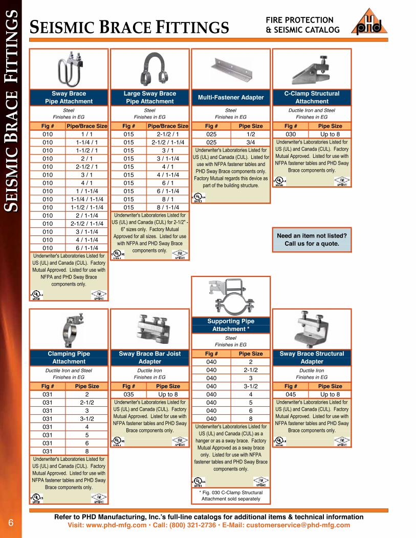
Fig # Pipe/Brace Size Fig # Pipe/Brace Size Fig # Pipe Size Fig # Pipe Size010 1 / 1 015 2-1/2 / 1 025 1/2 030 Up to 8010 1-1/4 / 1 015 2-1/2 / 1-1/4 025 3/4010 1-1/2 / 1 015 3 / 1010 2 / 1 015 3 / 1-1/4010 2-1/2 / 1 015 4 / 1010 3 / 1 015 4 / 1-1/4010 4 / 1 015 6 / 1010 1 / 1-1/4 015 6 / 1-1/4010 1-1/4 / 1-1/4 015 8 / 1010 1-1/2 / 1-1/4 015 8 / 1-1/4010 2 / 1-1/4010 2-1/2 / 1-1/4010 3 / 1-1/4010 4 / 1-1/4010 6 / 1-1/4
Fig # Pipe Size040 2040 2-1/2040 3
Fig # Pipe Size Fig # Pipe Size 040 3-1/2 Fig # Pipe Size031 2 035 Up to 8 040 4 045 Up to 8031 2-1/2 040 5031 3 040 6031 3-1/2 040 8031 4031 5031 6031 8
C-Clamp Structural Attachment
Ductile Iron and SteelFinishes in EG
Multi-Fastener Adapter
SteelFinishes in EG
Underwriter's Laboratories Listed for US (UL) and Canada (CUL). Listed for
use with NFPA fastener tables and PHD Sway Brace components only.
Factory Mutual regards this device as part of the building structure.
Finishes in EG
Supporting Pipe Attachment *
Finishes in EG
Underwriter's Laboratories Listed for US (UL) and Canada (CUL). Factory Mutual Approved. Listed for use with NFPA fastener tables and PHD Sway
Brace components only.
Need an item not listed? Call us for a quote.
Underwriter's Laboratories Listed for US (UL) and Canada (CUL). Factory Mutual Approved. Listed for use with NFPA fastener tables and PHD Sway
Brace components only.
Steel
Sway Brace Structural Adapter
Ductile Iron
Sway BracePipe Attachment
Steel
Underwriter's Laboratories Listed for US (UL) and Canada (CUL) for 2-1/2" -
6" sizes only. Factory Mutual Approved for all sizes. Listed for use
with NFPA and PHD Sway Brace components only.
Large Sway BracePipe Attachment
SteelFinishes in EGFinishes in EG
Underwriter's Laboratories Listed for US (UL) and Canada (CUL). Factory Mutual Approved. Listed for use with
NFPA and PHD Sway Brace components only.
Clamping Pipe Attachment
* Fig. 030 C-Clamp Structural Attachment sold separately
Ductile Iron and SteelFinishes in EG
Underwriter's Laboratories Listed for US (UL) and Canada (CUL). Factory Mutual Approved. Listed for use with NFPA fastener tables and PHD Sway
Brace components only.
Sway Brace Bar Joist Adapter
Ductile IronFinishes in EG
Underwriter's Laboratories Listed for US (UL) and Canada (CUL). Factory Mutual Approved. Listed for use with NFPA fastener tables and PHD Sway
Brace components only.Underwriter's Laboratories Listed for
US (UL) and Canada (CUL) as a hanger or as a sway brace. Factory Mutual Approved as a sway brace
only. Listed for use with NFPA fastener tables and PHD Sway Brace
components only.
SEIS
MIC
BRA
CE F
ITTI
NG
SSEISMIC BRACE FITTINGS FIRE PROTECTION
& SEISMIC CATALOG

7Refer to PHD Manufacturing, Inc.’s full-line catalogs for additional items & technical informationVisit: www.phd-mfg.com • Call: (800) 321-2736 • E-Mail: [email protected] 7
CPVC STRA
PS & A
TTACH
MEN
TSCPVC STRAPS & ATTACHMENTSPHD CPVC STRAPS
Fig # Pipe Size Fig # Pipe Size Fig # Pipe Size Fig # Pipe Size070 3/4 075 3/4 076 3/4 077 3/4070 1 075 1 076 1 077 1070 1-1/4 075 1-1/4 076 1-1/4 077 1-1/4070 1-1/2 075 1-1/2 076 1-1/2 077 1-1/2070 2 075 2 076 2 077 2
PHD ATTACHMENTS
Fig # Rod Size Fig # Rod Size Fig # Pipe Size Fig # Rod Size36 3/8 37 3/8 874 2 906 3/8
37 1/2 874 2-1/2874 3874 3-1/2874 4874 5874 6874 8874 10874 12
945 EGFig # Size # Fig # Rod Size 946 CP910 1 925 3/8 or 1/2 Fig # Rod Size910 2 945 or 946 3/8910 3910 4
Federal Specification A-A-1192A (Type 34) and MSS ANSI/SP-69 and
SP-58 (Type 34) compliant.Underwriter's Laboratories Listed in the US (UL) and Canada (CUL) for supporting up to 2" pipe max. (Fig.
945 only)
Federal Specification A-A-1192A (Type 38) and MSS ANSI/SP-69 and
SP-58 (Type 38) compliant.
Reversible Angle Bracket Reversible Side Beam Angle Bracket Steel Ceiling Plate
Steel, available in SS & SX Steel Can't find what you're looking for?
Call us for more information.
SteelFinishes in PL or EG Finishes in PL or EG
Finishes in EG Finishes in EG Finishes in PL or EG Finishes in PL or EG
Underwriter's Laboratories Listed in the US (UL) and Factory Mutual
Approved.
Federal Specification A-A-1192A (Type 34) and MSS ANSI/SP-69 and
SP-58 (Type 34) compliant.Underwriters' Laboratories Listed in the US (UL) and Canada (CUL) for
3/8" and 1/2" rod sizes. Factory Mutual Approved for 3/8" rod size only.
Underwriter's Laboratories Listed in the US (UL) and Canada (CUL), and
Factory Mutual Approved.
Steel Eye Socket Steel Eye Socket Pipe Saddle Supportwith Stud
SteelSide Beam Connector
Steel Steel Steel, available in SS & SX Steel
Finishes in PG Finishes in PG Finishes in PG Finishes in PG
Underwriter's Laboratories Listed in the US (UL) andCanada (CUL).
Underwriter's Laboratories Listed in the US (UL) andCanada (CUL).
Underwriter's Laboratories Listed in the US (UL) andCanada (CUL).
Underwriter's Laboratories Listed in the US (UL) andCanada (CUL).
CPVC Two-HolePipe Strap
CPVC One-HoleWrap Around
CPVC Two-HoleStand Off Strap
CPVC Two-HoleSide Mount Strap
Steel Steel Steel Steel

Refer to PHD Manufacturing, Inc.’s full-line catalogs for additional items & technical informationVisit: www.phd-mfg.com • Call: (800) 321-2736 • E-Mail: [email protected]
PHD THREADED ACCESSORIES
Fig # Rod Size Fig # Rod Size * Fig # Rod Size Fig # Length020 3/8 10 3/8 40 3/8 45 1-1/2
10 1/2 40 1/2 45 210 5/8 45 2-1/210 3/4 45 310 7/8 45 4
Fig # Rod Size Fig # Size 50 RH Threads Fig # Rod Size47S Drop In 3/8 48 12 - 1-1/2" 50L LH Threads 100 1/447S Drop In 1/2 48 12 - 2" Fig # Rod Size * 100 3/847S Drop In 5/8 48 14 - 1-1/2" 50 or 50L 3/8 100 1/2
48 14 - 2" 50 or 50L 1/2 100 5/848 16 - 2" 50 or 50L 5/8 100 3/4
50 or 50L 3/4 100 7/850 or 50L 7/8 100 150 or 50L 1
Fig # Rod Size 110 Standard104 3/8 110H Heavy104 1/2 Fig # Rod Size
110 or 110H 1/4 Fig # Rod Size110 or 110H 5/16 130 1/4110 or 110H 3/8 130 3/8110 or 110H 1/2 130 1/2110 or 110H 5/8 130 5/8110 or 110H 3/4 130 3/4110 or 110H 7/8 130 7/8110 or 110H 1 130 1110 or 110H 1-1/8 130 1-1/8110 or 110H 1-1/4 130 1-1/4110 or 110H 1-1/2 130 1-1/2
* Specify 4", 6", 8", 10" or 12" length
Steel, available in SS & SX
Standard Rod Coupling
Flat Washer
Steel, available in SS & SX
Finishes in PL or EG
Eye Rod
Steel, available in SS & SXFinishes in PL or EG
* Specify length
Finishes in PL or EG
Lag Screw
Steel
Coach Screw Rod
SteelFinishes in PL or EGFinishes in EG
Threaded Studs
Steel, available in SS & SX
Rod Swivel Attachment
SteelFinishes in PL or EG
Underwriters Laboratories Listed in the U.S. (UL) and Canada (CUL).
Need an item not listed? Call us for a quote.
Finishes in PL or EG
SteelFinishes in PL or EG
Steel, available in SS & SX
Short PatternRod Coupling Hex Nut
Finishes in PL or EG
* Specify length
Steel Steel
Concrete Anchors
Finishes in PL or EG
Wood Drive Screw
Finishes in EG
THRE
AD
ED A
CCES
SORI
ES THREADED ACCESSORIES FIRE PROTECTION& SEISMIC CATALOG

9Refer to PHD Manufacturing, Inc.’s full-line catalogs for additional items & technical informationVisit: www.phd-mfg.com • Call: (800) 321-2736 • E-Mail: [email protected] 9
PHD CHANNEL / STRUT
10 Ft-Fig # 20 Ft-Fig # 10 Ft-Fig # 20 Ft-Fig # 10 Ft-Fig # 20 Ft-Fig #
1001 1002 1501 1502 1601 1602
1001A 1002A 1501A 1502A 1601A 1602A
1011 1012 1511 1512 1611 1612
1011A 1012A 1511A 1512A 1611A 1612A
1021 1022 1521 1522 1621 1622
1021A 1022A 1521A 1522A 1621A 1622A
1031 1032 1531 1532 1631 1632
1041 1042 1541 1542 1641 1642
Fig # Pipe Size Fig # Size Fig # Size2001 3/8 3001 #8-32 3101 #8-322002 1/2 3002 #10-24 3102 #10-242003 3/4 3003 #10-32 3103 #10-322004 1 3004 * 1/4 3104 * 1/42005 1-1/4 3005 5/16 3105 5/162006 1-1/2 3006 * 3/8 3106 * 3/82007 2 3007 7/16 3107 7/16
2008 * 2-1/2 3008 * 1/2 3108 * 1/22009 * 3 3009 5/8 3109 5/82010 * 3-1/2 3010 3/4 3110 3/42011 * 4 3011 7/8 3111 7/82012 52013 62014 82015 102016 12
Finishes in EG Finishes in EG Finishes in EG
Can't find what you're looking for?
Call us for more information.* Universal for EMT
* Welded Back toBack Strut
GRC & STDPipe Clamp Strut Nut without Spring Strut Nut with Spring
Steel, available SS & SX Steel, * available in SS & SX Steel, * available in SS & SX
1-1/8" X 9/16" Slots on 2" Centers
Welded Back to Back * 9/16" Dia. Holes on
1-7/8" Centers
Welded Back to Back * 3" Slots
7/8" Knockouts on6" Centers
Finishes in PL, PG, PTD Finishes in PL, PG, PTD Finishes in PL, PG, PTDProfiles
Solid
Welded Back to Back *
1-5/8" X 1-5/8" X 12 Gauge
1-5/8" X 3-1/4" X 12 Gauge
1-5/8" X 2-7/16" X 12 Gauge
Steel, available SS & SX Steel, available SS & SX Steel, available SS & SX
CH
AN
NEL / STRU
TCHANNEL/STRUT

Refer to PHD Manufacturing, Inc.’s full-line catalogs for additional items & technical informationVisit: www.phd-mfg.com • Call: (800) 321-2736 • E-Mail: [email protected]
Unless otherwise specified, all dimensions on drawings and in charts are in inches and dimensions shown in parentheses are in millimeters.
10
PHD
SEI
SMIC
PRO
DU
CTS
This map shows the relative ground motion hazards in the United States during a 50-year time period. Map not to scale. Source: USGS.
SeismicEvent
HighestHazard
Seismic Activity Zone Map
Architects can count on PHD's seismic parts to comply with the building code regulations governed by the IBC (International Building Code), which considers the following parameters: • Ground motion maps• Seismic design categories (SDC) • Building importance factors• MEPF utility importance factor based on end use (IP)• Ratio of building height vs. elevation of the utility being braced.
Refer to PHD Manufacturing, Inc.’s full-line catalogs for additional items & technical informationVisit: www.phd-mfg.com • Call: (800) 321-2736 • E-Mail: [email protected]
Unless otherwise specified, all dimensions on drawings and in charts are in inches and dimensions shown in parentheses are in millimeters.
11
SWAY B
RACE FITTIN
GS
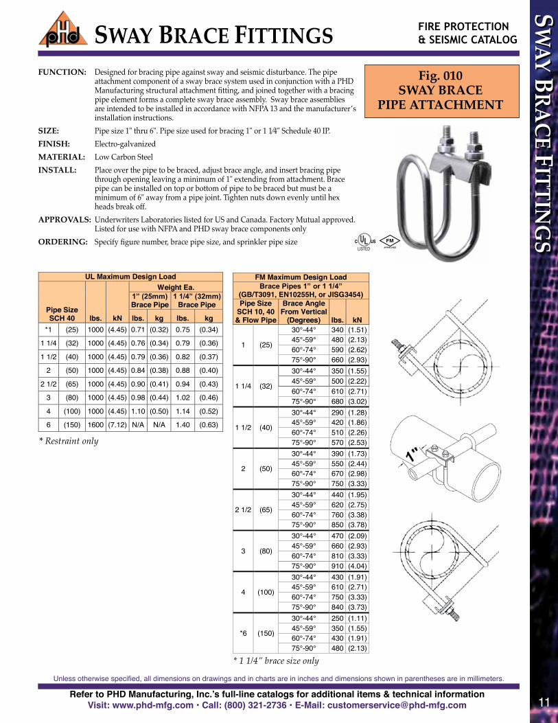
SWAY BRACE FITTINGSFig. 010
SWAY BRACEPIPE ATTACHMENT
FUNCTION: Designed for bracing pipe against sway and seismic disturbance. The pipe attachment component of a sway brace system used in conjunction with a PHD Manufacturing structural attachment fitting, and joined together with a bracing pipe element forms a complete sway brace assembly. Sway brace assemblies are intended to be installed in accordance with NFPA 13 and the manufacturer’s installation instructions.
SIZE: Pipe size 1" thru 6". Pipe size used for bracing 1" or 1 1⁄4" Schedule 40 IP.FINISH: Electro-galvanizedMATERIAL: Low Carbon SteelINSTALL: Place over the pipe to be braced, adjust brace angle, and insert bracing pipe
through opening leaving a minimum of 1" extending from attachment. Brace pipe can be installed on top or bottom of pipe to be braced but must be a minimum of 6" away from a pipe joint. Tighten nuts down evenly until hex heads break off.
APPROVALS: Underwriters Laboratories listed for US and Canada. Factory Mutual approved. Listed for use with NFPA and PHD sway brace components only
ORDERING: Specify figure number, brace pipe size, and sprinkler pipe size
FIRE PROTECTION& SEISMIC CATALOG
UL Maximum Design Load
Pipe Size SCH 40 lbs. kN
Weight Ea. 1” (25mm) Brace Pipe
1 1/4” (32mm) Brace Pipe
lbs. kg lbs. kg *1 (25) 1000 (4.45) 0.71 (0.32) 0.75 (0.34)
1 1/4 (32) 1000 (4.45) 0.76 (0.34) 0.79 (0.36)
1 1/2 (40) 1000 (4.45) 0.79 (0.36) 0.82 (0.37)
2 (50) 1000 (4.45) 0.84 (0.38) 0.88 (0.40)
2 1/2 (65) 1000 (4.45) 0.90 (0.41) 0.94 (0.43)
3 (80) 1000 (4.45) 0.98 (0.44) 1.02 (0.46)
4 (100) 1000 (4.45) 1.10 (0.50) 1.14 (0.52)
6 (150) 1600 (7.12) N/A N/A 1.40 (0.63)
FM Maximum Design Load Brace Pipes 1” or 1 1/4”
(GB/T3091, EN10255H, or JISG3454) Pipe Size
SCH 10, 40 & Flow Pipe
Brace Angle From Vertical
(Degrees) lbs. kN
1 (25)
30°-44° 340 (1.51) 45°-59° 480 (2.13) 60°-74° 590 (2.62) 75°-90° 660 (2.93)
1 1/4 (32)
30°-44° 350 (1.55) 45°-59° 500 (2.22) 60°-74° 610 (2.71) 75°-90° 680 (3.02)
1 1/2 (40)
30°-44° 290 (1.28) 45°-59° 420 (1.86) 60°-74° 510 (2.26) 75°-90° 570 (2.53)
2 (50)
30°-44° 390 (1.73) 45°-59° 550 (2.44) 60°-74° 670 (2.98) 75°-90° 750 (3.33)
2 1/2 (65)
30°-44° 440 (1.95) 45°-59° 620 (2.75) 60°-74° 760 (3.38) 75°-90° 850 (3.78)
3 (80)
30°-44° 470 (2.09) 45°-59° 660 (2.93) 60°-74° 810 (3.33) 75°-90° 910 (4.04)
4 (100)
30°-44° 430 (1.91) 45°-59° 610 (2.71) 60°-74° 750 (3.33) 75°-90° 840 (3.73)
*6 (150)
30°-44° 250 (1.11) 45°-59° 350 (1.55) 60°-74° 430 (1.91) 75°-90° 480 (2.13)
SWAY BRACE FITTINGS
Fig. 010 SWAY BRACE
PIPE ATTACHMENT
FUNCTION: Designed for bracing pipe against sway and seismic disturbance. The pipe attachment component of a sway brace system used in conjunction with a PHD Manufacturing structural attachment fitting, and joined together with a bracing pipe element forms a complete sway brace assembly. Sway brace assemblies are intended to be installed in accordance with NFPA 13 and the manufacturer’s installation instructions.
SIZE: Pipe size 1" thru 6". Pipe size used for bracing 1" or 1 1⁄4" Schedule 40 IP.
FINISH: Electro-galvanized MATERIAL: Low Carbon Steel INSTALL: Place over the pipe to be braced, adjust brace angle, and insert bracing
pipe through opening leaving a minimum of 1" extending from attachment. Brace pipe can be installed on top or bottom of pipe to be braced but must be a minimum of 6" away from a pipe joint. Tighten nuts down evenly until hex heads break off.
APPROVALS: Underwriters Laboratories listed for US and Canada Factory Mutual approved Listed for use with NFPA and PHD sway brace components only
ORDERING: Specify figure number, brace pipe size, and sprinkler pipe size
PHD Manufacturing, Inc.
Unless otherwise specified, all dimensions on drawings and in charts are in inches and dimensions shown in parentheses are in millimeters.
* Restraint only
* 1 1/4” brace size only

Refer to PHD Manufacturing, Inc.’s full-line catalogs for additional items & technical informationVisit: www.phd-mfg.com • Call: (800) 321-2736 • E-Mail: [email protected]
Unless otherwise specified, all dimensions on drawings and in charts are in inches and dimensions shown in parentheses are in millimeters.
12
SWAY
BRA
CE F
ITTI
NG
S SWAY BRACE FITTINGSFig. 015
LARGE SWAY BRACEPIPE ATTACHMENT
FUNCTION: Designed for bracing pipe against sway and seismic disturbance. The pipe attachment component of a sway brace system used in conjunc-tion with a PHD Manufacturing structural attachment fitting, and joined together with a bracing pipe element forms a complete sway brace assembly. Sway brace assemblies are intended to be installed in accordance with NFPA 13 and the manufacturer’s installation instruc-tions.
SIZE: Pipe size 2-1/2” thru 8”.Pipe size used for bracing 1” or 1-1⁄4” Schedule 40 IP.
FINISH: Electro-galvanizedMATERIAL: Low Carbon SteelINSTALL: Place over the pipe to be braced, adjust brace angle, and insert bracing
pipe through opening leaving a minimum of 1” extending from attach-ment. Brace pipe can be installed on top or bottom of pipe to be braced but must be a minimum of 6” away from a pipe joint. Tighten two hex head cone point set bolts until heads bottom out on attachment, ensur-ing proper torque has been applied.
APPROVALS: Underwriters Laboratories listed for US and Canada (2-1/2“ thru 6” only). Factory Mutual approved.Listed for use with NFPA and PHD sway brace components only
ORDERING: Specify figure number, brace pipe size, and sprinkler pipe size
FM Maximum Design Load Brace: 1” Thru 2” SCH40 Pipe
( GB/T3091, EN10255H, or JISG3454)
Pipe Size SCH 10, 40 & Flow Pipe
Brace Angle From Vertical
(Degrees) lbs. kN
Weight Ea. 1” (25mm) Brace Pipe
1 1/4” (32mm) Brace Pipe
lbs. kg lbs. kg
2 1/2 (65)
30°-44° 1020 (4.53)
1.31 (0.59) 1.49 (0.68) 45°-59° 1440 (6.40)
60°-74° 1770 (7.87)
75°-90° 1970 (8.76)
3 (80)
30°-44° 1080 (4.80)
1.40 (0.64) 1.57 (0.71) 45°-59° 1530 (6.80)
60°-74° 1870 (8.31)
75°-90° 2090 (9.29)
4 (100)
30°-44° 1020 (4.53)
1.53 (0.69) 1.70 (0.77) 45°-59° 1450 (6.44)
60°-74° 1770 (7.87)
75°-90° 1980 (8.80)
6 (150)
30°-44° 640 (2.84)
1.81 (0.82) 1.98 (0.90) 45°-59° 900 (4.00)
60°-74° 1110 (4.93)
75°-90° 1240 (5.51)
8 (200)
30°-44° 570 (2.53)
2.07 (0.94) 2.24 (1.02) 45°-59° 810 (3.60) 60°-74° 990 (4.40) 75°-90° 1100 (4.89)
UL Maximum Design Load Pipe Size
SCH 10 & 40 lbs. kN 2 1/2 (65) 1000 (4.45)
3 (80) 1000 (4.45)
4 (100) 1000 (4.45)
6 (150) 1600 (7.12)
Fig. 015 LARGE SWAY BRACE PIPE ATTACHMENT
FUNCTION: Designed for bracing pipe against sway and seismic disturbance. The pipe attachment component of a sway brace system used in conjunction with a PHD Manufacturing structural attachment fitting, and joined together with a bracing pipe element forms a complete sway brace assembly. Sway brace assemblies are intended to be installed in accordance with NFPA 13 and the manufacturer’s installation instructions.
SIZE: Pipe size 2-‐‑1/2"ʺ thru 8"ʺ. Pipe size used for bracing 1"ʺ or 1 1⁄4"ʺ Schedule 40 IP.
FINISH: Electro-‐‑galvanized MATERIAL: Low Carbon Steel INSTALL: Place over the pipe to be braced, adjust brace angle, and insert bracing
pipe through opening leaving a minimum of 1"ʺ extending from attachment. Brace pipe can be installed on top or bottom of pipe to be braced but must be a minimum of 6"ʺ away from a pipe joint. Tighten two hex head cone point set bolts until heads bottom out on attachment, ensuring proper torque has been applied.
APPROVALS: Underwriters Laboratories listed for US and Canada (2 1/2“ thru 6” only) Factory Mutual approved Listed for use with NFPA and PHD sway brace components only
ORDERING: Specify figure number, brace pipe size, and sprinkler pipe size
SWAY BRACE FITTINGS
PHD Manufacturing, Inc.
Unless otherwise specified, all dimensions on drawings and in charts are in inches and dimensions shown in parentheses are in millimeters.

Refer to PHD Manufacturing, Inc.’s full-line catalogs for additional items & technical informationVisit: www.phd-mfg.com • Call: (800) 321-2736 • E-Mail: [email protected]
Unless otherwise specified, all dimensions on drawings and in charts are in inches and dimensions shown in parentheses are in millimeters.
13
UL Maximum Design Loads All Pipe Sizes, SCH 10 & 40 (3 1/2 SCH 40 only)
Lateral & Longitudinal Assemblies
Brace Member Member
Thickness Member Length lbs. kN 1” Thru 2” Pipe SCH 40 Refer to NFPA13 2015 (8.96)
Structural Steel 1/4” & 3/8” thick Refer to NFPA13 2015 (8.96)
1001 Series Strut 12 Ga. See Chart Below 2015 (8.96)
1201 Series Strut 12 Ga. See Chart Below 2015 (8.96)
FM Maximum Design Load (All Sizes) For Bracing SCH 10, 40 & Flow Pipe
Brace Member Direction
Brace Angle
(Degrees) lbs. kN
1” Thru 2” SCH 40 Pipe
(GB/T3091, EN10255H,
or JISG3454) Lateral
30°-44° 1270 (5.64)
45°-59° 1800 (9.07)
60°-74° 2200 (10.89)
75°-90° 2460 (12.18)
1/4" Thru 3/8” Thick Structural Steel
Lateral & Longitudinal
30°-44° 900 (4.00)
45°-59° 1280 (5.69)
60°-74° 1570 (6.98)
75°-90° 1750 (7.78)
PHD 12 Gauge Strut Channel 1001 & 1201
Lateral & Longitudinal
30°-44° 1070 (4.75)
45°-59° 1440 (6.40)
60°-74° 1740 (7.73)
75°-90° 1940 (8.62)
Strut Fig. #
PHD Strut Channel Maximum Horizontal Load 90° From Vertical
r l/r = 100 200 300
Max lbs. kN Max lbs. kN Max lbs. kN 1001 0.580 (14.73) 58” (1473.2) 4670 (20.77) 116” (2946.4) 1165 (5.18) 174” (4419.6) 518 (2.30) 1201 0.297 (7.54) 29” (736.6) 3260 (14.50) 59” (1498.6) 785 (3.49) 89” (2260.6) 345 (1.53)
FM Maximum Design Load Brace: 1” Thru 2” SCH40 Pipe
( GB/T3091, EN10255H, or JISG3454) Pipe Size
SCH 10, 40 & Flow Pipe
Brace Angle From Vertical
(Degrees) Longitudinal Weight Ea. lbs. kN lbs. kg
2 (50)
30°-44° 1370 (6.09)
2.60 (1.18) 45°-59° 1930 (8.58)
60°-74° 2370 (10.54)
75°-90° 2810 (12.49)
2 1/2 (65)
30°-44° 1500 (6.67)
2.77 (1.26) 45°-59° 2120 (9.43)
60°-74° 2600 (11.56)
75°-90° 2900 (12.89)
3 (80)
30°-44° 1370 (6.09)
3.00 (1.36) 45°-59° 1930 (8.58)
60°-74° 2370 (10.54)
75°-90° 2810 (12.49)
3 1/2 (90)
30°-44° 1370 (6.09)
3.13 (1.42) 45°-59° 1930 (8.58)
60°-74° 2370 (10.54)
75°-90° 2810 (12.49)
4 (100)
30°-44° 1370 (6.09)
3.30 (1.50) 45°-59° 1930 (8.58)
60°-74° 2370 (10.54)
75°-90° 2810 (12.49)
5 (125)
30°-44° 1370 (6.09)
4.57 (2.07) 45°-59° 1930 (8.58)
60°-74° 2370 (10.54)
75°-90° 2810 (12.49)
6 (150)
30°-44° 1410 (6.27)
5.42 (2.46) 45°-59° 2000 (8.89)
60°-74° 2450 (10.89)
75°-90° 2730 (12.14)
8 (200)
30°-44° 1320 (5.87)
8.52 (3.86) 45°-59° 1870 (8.31) 60°-74° 2290 (10.18) 75°-90° 2550 (11.34)
Fig. 031 CLAMPING
PIPE ATTACHMENT
FUNCTION: Designed for bracing pipe against sway and seismic disturbance. Versatile design allows for attachment at any angle and the ability to be used in a lateral or longitudinal bracing configuration. The pipe attachment component of a sway brace system used in conjunction with a PHD Manufacturing structural attachment fitting and joined together with a bracing element form a complete sway brace assembly. Sway brace assemblies are intended to be installed in accordance with NFPA 13 and the manufacturer’s installation instructions.
SIZE: Pipe sizes 2"ʺ thru 8"ʺ. Can use 1” thru 2” SCH 40 pipe, structural steel, and PHD 12 gauge strut channel (1001 & 1201) as sway bracing elements.
FINISH: Electro-‐‑galvanized MATERIAL: Ductile Iron and Low Carbon Steel, Grade 5 clamping bolts
PHD Manufacturing, Inc.
Unless otherwise specified, all dimensions on drawings and in charts are in inches and dimensions shown in parentheses are in millimeters.
SWAY BRACE FITTINGS
INSTALL: Place attachment around pipe to be braced, positioning brace attachment as needed, then tighten clamping bolts and nuts finger tight. Insert brace component into fitting against back of jaw. Tighten set screw finger tight, adjust brace angle as needed, then tighten set screw until hex head breaks off. Then evenly torque clamping bolts until hex portion of clamping nuts break off.
APPROVALS: Underwriters Laboratories listed for US and Canada Factory Mutual approved
Listed for use with PHD sway brace components only ORDERING: Specify figure number and sprinkler pipe size
FUNCTION: Designed for bracing pipe against sway and seismic disturbance. Versatile design allows for attachment at any angle and the ability to be used in a lateral or longitudinal bracing configuration. The pipe attachment component of a sway brace system used in conjunction with a PHD Manufacturing structural attachment fitting and joined together with a bracing element form a complete sway brace assembly. Sway brace assemblies are intended to be installed in accordance with NFPA 13 and the manufacturer’s installation instructions.
SIZE: Pipe sizes 2" thru 8".Can use 1” thru 2” SCH 40 pipe, structural steel, and PHD 12 gauge strut channel (1001 & 1201) as sway bracing elements.
FINISH: Electro-galvanizedMATERIAL: Ductile Iron and Low Carbon Steel, Grade 5 clamping bolts
INSTALL: Place attachment around pipe to be braced, positioning brace attachment as needed, then tighten clamping bolts and nuts finger tight. Insert brace component into fitting against back of jaw. Tighten set screw finger tight, adjust brace angle as needed, then tighten set screw until hex head breaks off. Then evenly torque clamping bolts until hex portion of clamping nuts break off.
APPROVALS: Underwriters Laboratories listed for US and Canada. Factory Mutual approved. Listed for use with PHD sway brace components only
ORDERING: Specify figure number and sprinkler pipe size
Fig. 031CLAMPING
PIPE ATTACHMENT
UL Maximum Design Loads All Pipe Sizes, SCH 10 & 40 (3 1/2 SCH 40 only)
Lateral & Longitudinal Assemblies
Brace Member Member
Thickness Member Length lbs. kN 1” Thru 2” Pipe SCH 40 Refer to NFPA13 2015 (8.96)
Structural Steel 1/4” & 3/8” thick Refer to NFPA13 2015 (8.96)
1001 Series Strut 12 Ga. See Chart Below 2015 (8.96)
1201 Series Strut 12 Ga. See Chart Below 2015 (8.96)
FM Maximum Design Load (All Sizes) For Bracing SCH 10, 40 & Flow Pipe
Brace Member Direction
Brace Angle
(Degrees) lbs. kN
1” Thru 2” SCH 40 Pipe
(GB/T3091, EN10255H,
or JISG3454) Lateral
30°-44° 1270 (5.64)
45°-59° 1800 (9.07)
60°-74° 2200 (10.89)
75°-90° 2460 (12.18)
1/4" Thru 3/8” Thick Structural Steel
Lateral & Longitudinal
30°-44° 900 (4.00)
45°-59° 1280 (5.69)
60°-74° 1570 (6.98)
75°-90° 1750 (7.78)
PHD 12 Gauge Strut Channel 1001 & 1201
Lateral & Longitudinal
30°-44° 1070 (4.75)
45°-59° 1440 (6.40)
60°-74° 1740 (7.73)
75°-90° 1940 (8.62)
Strut Fig. #
PHD Strut Channel Maximum Horizontal Load 90° From Vertical
r l/r = 100 200 300
Max lbs. kN Max lbs. kN Max lbs. kN 1001 0.580 (14.73) 58” (1473.2) 4670 (20.77) 116” (2946.4) 1165 (5.18) 174” (4419.6) 518 (2.30) 1201 0.297 (7.54) 29” (736.6) 3260 (14.50) 59” (1498.6) 785 (3.49) 89” (2260.6) 345 (1.53)
FM Maximum Design Load Brace: 1” Thru 2” SCH40 Pipe
( GB/T3091, EN10255H, or JISG3454) Pipe Size
SCH 10, 40 & Flow Pipe
Brace Angle From Vertical
(Degrees) Longitudinal Weight Ea. lbs. kN lbs. kg
2 (50)
30°-44° 1370 (6.09)
2.60 (1.18) 45°-59° 1930 (8.58)
60°-74° 2370 (10.54)
75°-90° 2810 (12.49)
2 1/2 (65)
30°-44° 1500 (6.67)
2.77 (1.26) 45°-59° 2120 (9.43)
60°-74° 2600 (11.56)
75°-90° 2900 (12.89)
3 (80)
30°-44° 1370 (6.09)
3.00 (1.36) 45°-59° 1930 (8.58)
60°-74° 2370 (10.54)
75°-90° 2810 (12.49)
3 1/2 (90)
30°-44° 1370 (6.09)
3.13 (1.42) 45°-59° 1930 (8.58)
60°-74° 2370 (10.54)
75°-90° 2810 (12.49)
4 (100)
30°-44° 1370 (6.09)
3.30 (1.50) 45°-59° 1930 (8.58)
60°-74° 2370 (10.54)
75°-90° 2810 (12.49)
5 (125)
30°-44° 1370 (6.09)
4.57 (2.07) 45°-59° 1930 (8.58)
60°-74° 2370 (10.54)
75°-90° 2810 (12.49)
6 (150)
30°-44° 1410 (6.27)
5.42 (2.46) 45°-59° 2000 (8.89)
60°-74° 2450 (10.89)
75°-90° 2730 (12.14)
8 (200)
30°-44° 1320 (5.87)
8.52 (3.86) 45°-59° 1870 (8.31) 60°-74° 2290 (10.18) 75°-90° 2550 (11.34)
Fig. 031 CLAMPING
PIPE ATTACHMENT
FUNCTION: Designed for bracing pipe against sway and seismic disturbance. Versatile design allows for attachment at any angle and the ability to be used in a lateral or longitudinal bracing configuration. The pipe attachment component of a sway brace system used in conjunction with a PHD Manufacturing structural attachment fitting and joined together with a bracing element form a complete sway brace assembly. Sway brace assemblies are intended to be installed in accordance with NFPA 13 and the manufacturer’s installation instructions.
SIZE: Pipe sizes 2"ʺ thru 8"ʺ. Can use 1” thru 2” SCH 40 pipe, structural steel, and PHD 12 gauge strut channel (1001 & 1201) as sway bracing elements.
FINISH: Electro-‐‑galvanized MATERIAL: Ductile Iron and Low Carbon Steel, Grade 5 clamping bolts
PHD Manufacturing, Inc.
Unless otherwise specified, all dimensions on drawings and in charts are in inches and dimensions shown in parentheses are in millimeters.
SWAY BRACE FITTINGS
INSTALL: Place attachment around pipe to be braced, positioning brace attachment as needed, then tighten clamping bolts and nuts finger tight. Insert brace component into fitting against back of jaw. Tighten set screw finger tight, adjust brace angle as needed, then tighten set screw until hex head breaks off. Then evenly torque clamping bolts until hex portion of clamping nuts break off.
APPROVALS: Underwriters Laboratories listed for US and Canada Factory Mutual approved
Listed for use with PHD sway brace components only ORDERING: Specify figure number and sprinkler pipe size
See application illustrationson page 19.
SWAY B
RACE FITTIN
GS
SWAY BRACE FITTINGS

Refer to PHD Manufacturing, Inc.’s full-line catalogs for additional items & technical informationVisit: www.phd-mfg.com • Call: (800) 321-2736 • E-Mail: [email protected]
Unless otherwise specified, all dimensions on drawings and in charts are in inches and dimensions shown in parentheses are in millimeters.
14
SWAY
BRA
CE F
ITTI
NG
S SWAY BRACE FITTINGSFig. 040
SUPPORTINGPIPE ATTACHMENT
Note: Figure 030 sold separately.
UL Maximum Design Load
Pipe Size SCH 10 & 40
Hanger Rod Size
Rec. Max. Hanger Load
Max. Design Sway Brace
Load Weight Ea.
lbs. kN lbs. kN lbs. kg 2 (50) 3/8 (10) 730 (3.25) 1000 (4.45) 2.40 (1.09)
2 1/2 (65) 1/2 (12) 850 (3.78) 1000 (4.45) 2.58 (1.17)
3 (80) 1/2 (12) 1000 (4.45) 1000 (4.45) 2.80 (1.27)
*3 1/2 (90) 1/2 (12) 1000 (4.45) 1000 (4.45) 2.94 (1.33)
4 (100) 5/8 (16) 1000 (4.45) 1000 (4.45) 3.28 (1.49)
5 (125) 5/8 (16) 1600 (7.12) 1600 (7.12) 4.95 (2.25)
6 (150) 3/4 (20) 1600 (7.12) 1600 (7.12) 6.93 (3.14)
8 (200) 3/4 (20) 2015 (8.96) 2015 (8.96) 9.97 (4.52)
FM Maximum Design Load Pipe Size
SCH 10, 40 & Flow Pipe
Brace Angle From Vertical
(Degrees)
Lateral Longitudinal
lbs. kN lbs. kN
2 (50)
30°-44° 1070 (4.75) 1260 (5.60)
45°-59° 1520 (6.76) 1440 (6.40)
60°-74° 1860 (8.27) 1740 (7.73)
75°-90° 2080 (9.25) 1940 (8.62)
2 1/2 (65)
30°-44° 960 (4.27) 1000 (4.44)
45°-59° 1360 (6.04) 1420 (6.31)
60°-74° 1670 (7.42) 1740 (7.73)
75°-90° 1860 (8.27) 1940 (8.62)
3 (80)
30°-44° 960 (4.27) 1000 (4.44)
45°-59° 1360 (6.04) 1420 (6.31)
60°-74° 1670 (7.42) 1740 (7.73)
75°-90° 1860 (8.27) 1940 (8.62)
3 1/2 (90)
30°-44° 960 (4.27) 1000 (4.44)
45°-59° 1360 (6.04) 1420 (6.31)
60°-74° 1670 (7.42) 1740 (7.73)
75°-90° 1860 (8.27) 1940 (8.62)
4 (100)
30°-44° 960 (4.27) 1110 (4.93)
45°-59° 1360 (6.04) 1490 (6.62)
60°-74° 1670 (7.42) 1800 (8.00)
75°-90° 1860 (8.27) 1920 (8.54)
5 (125)
30°-44° 960 (4.27) 1110 (4.93)
45°-59° 1360 (6.04) 1490 (6.62)
60°-74° 1670 (7.42) 1800 (8.00)
75°-90° 1860 (8.27) 1920 (8.54)
6 (150)
30°-44° 1000 (4.44) 1280 (5.69)
45°-59° 1420 (6.31) 1810 (8.05)
60°-74° 1740 (7.73) 2210 (9.83)
75°-90° 1940 (8.62) 2470 (10.98)
8 (200)
30°-44° 1350 (6.00) 1160 (5.15) 45°-59° 1900 (8.45) 1650 (7.33) 60°-74° 2330 (10.36) 2020 (8.98) 75°-90° 2600 11.56) 2250 (10.00)
PHD Manufacturing, Inc.
SWAY BRACE FITTINGS FUNCTION: Designed for bracing pipe against sway and seismic disturbance. Versatile
design allows for attachment at any angle and the ability to be used in a lateral or longitudinal bracing configuration. The pipe attachment component of a sway brace system used in conjunction with two PHD Manufacturing structural attachment fittings and joined together with a bracing element form a complete sway brace assembly. Sway brace assemblies are intended to be installed in accordance with NFPA 13 and the manufacturer’s installation instructions.
SIZE: Pipe sizes 2"ʺ thru 8"ʺ. Refer to PHD Structural attachment fitting literature regarding appropriate brace members, sizes, and further loading limitations.
FINISH: Electro-‐‑galvanized MATERIAL: Low Carbon Steel, Grade 5 clamping bolts INSTALL: Attach PHD Manufacturing structural attachment fitting, Fig. 030 (sold
separately), to Fig. 040 using supplied fastener. Place the assembly around the pipe to be braced, positioning welded clevis on top of the pipe, then tighten clamping bolts and nuts finger tight. Follow PHD Manufacturing structural attachment fitting’s instructions for attaching to
Fig. 040 SUPPORTING
PIPE ATTACHMENT
Note: Figure 030 sold separately.
brace element. Adjust the brace element to the desired angle then tighten the supplied fastener to lock the PHD Manufacturing structural attachment fitting, Fig. 030, securely in position with the Fig. 040. Then evenly torque clamping bolts until hex portion of clamping nuts break off.
APPROVALS: Underwriters Laboratories listed for US and Canada as a hanger, a sway brace, or as both functions at the same time
Factory Mutual approved as a sway brace only Listed for use with PHD sway brace components only
ORDERING: Specify figure number and sprinkler pipe size
*SCH 40 only
Unless otherwise specified, all dimensions on drawings and in charts are in inches and dimensions shown in parentheses are in millimeters.
(Lateral Brace) (Longitudinal Brace)
FUNCTION: Designed for bracing pipe against sway and seismic disturbance. Versatile design allows for attachment at any angle and the ability to be used in a lateral or longitudinal bracing configuration. The pipe attachment component of a sway brace system used in conjunction with two PHD Manufacturing structural attachment fittings and joined together with a bracing element form a complete sway brace assembly. Sway brace assemblies are intended to be installed in accordance with NFPA 13 and the manufacturer’s installation instructions.
SIZE: Pipe sizes 2" thru 8". Refer to PHD Structural attachment fitting literature regarding appropriate brace members, sizes, and further loading limitations.
FINISH: Electro-galvanizedMATERIAL: Low Carbon Steel, Grade 5 clamping boltsINSTALL: Attach PHD Manufacturing structural attachment fitting, Fig. 030 (sold
separately), to Fig. 040 using supplied fastener. Place the assembly around the pipe to be braced, positioning welded clevis on top of the pipe, then tighten clamping bolts and nuts finger tight. Follow PHD
UL Maximum Design Load
Pipe Size SCH 10 & 40
Hanger Rod Size
Rec. Max. Hanger Load
Max. Design Sway Brace
Load Weight Ea.
lbs. kN lbs. kN lbs. kg 2 (50) 3/8 (10) 730 (3.25) 1000 (4.45) 2.40 (1.09)
2 1/2 (65) 1/2 (12) 850 (3.78) 1000 (4.45) 2.58 (1.17)
3 (80) 1/2 (12) 1000 (4.45) 1000 (4.45) 2.80 (1.27)
*3 1/2 (90) 1/2 (12) 1000 (4.45) 1000 (4.45) 2.94 (1.33)
4 (100) 5/8 (16) 1000 (4.45) 1000 (4.45) 3.28 (1.49)
5 (125) 5/8 (16) 1600 (7.12) 1600 (7.12) 4.95 (2.25)
6 (150) 3/4 (20) 1600 (7.12) 1600 (7.12) 6.93 (3.14)
8 (200) 3/4 (20) 2015 (8.96) 2015 (8.96) 9.97 (4.52)
FM Maximum Design Load Pipe Size
SCH 10, 40 & Flow Pipe
Brace Angle From Vertical
(Degrees)
Lateral Longitudinal
lbs. kN lbs. kN
2 (50)
30°-44° 1070 (4.75) 1260 (5.60)
45°-59° 1520 (6.76) 1440 (6.40)
60°-74° 1860 (8.27) 1740 (7.73)
75°-90° 2080 (9.25) 1940 (8.62)
2 1/2 (65)
30°-44° 960 (4.27) 1000 (4.44)
45°-59° 1360 (6.04) 1420 (6.31)
60°-74° 1670 (7.42) 1740 (7.73)
75°-90° 1860 (8.27) 1940 (8.62)
3 (80)
30°-44° 960 (4.27) 1000 (4.44)
45°-59° 1360 (6.04) 1420 (6.31)
60°-74° 1670 (7.42) 1740 (7.73)
75°-90° 1860 (8.27) 1940 (8.62)
3 1/2 (90)
30°-44° 960 (4.27) 1000 (4.44)
45°-59° 1360 (6.04) 1420 (6.31)
60°-74° 1670 (7.42) 1740 (7.73)
75°-90° 1860 (8.27) 1940 (8.62)
4 (100)
30°-44° 960 (4.27) 1110 (4.93)
45°-59° 1360 (6.04) 1490 (6.62)
60°-74° 1670 (7.42) 1800 (8.00)
75°-90° 1860 (8.27) 1920 (8.54)
5 (125)
30°-44° 960 (4.27) 1110 (4.93)
45°-59° 1360 (6.04) 1490 (6.62)
60°-74° 1670 (7.42) 1800 (8.00)
75°-90° 1860 (8.27) 1920 (8.54)
6 (150)
30°-44° 1000 (4.44) 1280 (5.69)
45°-59° 1420 (6.31) 1810 (8.05)
60°-74° 1740 (7.73) 2210 (9.83)
75°-90° 1940 (8.62) 2470 (10.98)
8 (200)
30°-44° 1350 (6.00) 1160 (5.15) 45°-59° 1900 (8.45) 1650 (7.33) 60°-74° 2330 (10.36) 2020 (8.98) 75°-90° 2600 11.56) 2250 (10.00)
PHD Manufacturing, Inc.
SWAY BRACE FITTINGS FUNCTION: Designed for bracing pipe against sway and seismic disturbance. Versatile
design allows for attachment at any angle and the ability to be used in a lateral or longitudinal bracing configuration. The pipe attachment component of a sway brace system used in conjunction with two PHD Manufacturing structural attachment fittings and joined together with a bracing element form a complete sway brace assembly. Sway brace assemblies are intended to be installed in accordance with NFPA 13 and the manufacturer’s installation instructions.
SIZE: Pipe sizes 2"ʺ thru 8"ʺ. Refer to PHD Structural attachment fitting literature regarding appropriate brace members, sizes, and further loading limitations.
FINISH: Electro-‐‑galvanized MATERIAL: Low Carbon Steel, Grade 5 clamping bolts INSTALL: Attach PHD Manufacturing structural attachment fitting, Fig. 030 (sold
separately), to Fig. 040 using supplied fastener. Place the assembly around the pipe to be braced, positioning welded clevis on top of the pipe, then tighten clamping bolts and nuts finger tight. Follow PHD Manufacturing structural attachment fitting’s instructions for attaching to
Fig. 040 SUPPORTING
PIPE ATTACHMENT
Note: Figure 030 sold separately.
brace element. Adjust the brace element to the desired angle then tighten the supplied fastener to lock the PHD Manufacturing structural attachment fitting, Fig. 030, securely in position with the Fig. 040. Then evenly torque clamping bolts until hex portion of clamping nuts break off.
APPROVALS: Underwriters Laboratories listed for US and Canada as a hanger, a sway brace, or as both functions at the same time
Factory Mutual approved as a sway brace only Listed for use with PHD sway brace components only
ORDERING: Specify figure number and sprinkler pipe size
*SCH 40 only
Unless otherwise specified, all dimensions on drawings and in charts are in inches and dimensions shown in parentheses are in millimeters.
(Lateral Brace) (Longitudinal Brace)
Manufacturing structural attachment fitting’s instructions for attaching to brace element. Adjust the brace element to the desired angle then tighten the supplied fastener to lock the PHD Manufacturing structural attachment fitting, Fig. 030, securely in position with the Fig. 040. Then evenly torque clamping bolts until hex portion of clamping nuts break off.
APPROVALS: Underwriters Laboratories listed for US and Canada as a hanger or as a sway brace. Factory Mutual approved as a sway brace only. Listed for use with PHD sway brace components only
ORDERING: Specify figure number and sprinkler pipe size
(As Hanger) (Lateral Brace) (Longitudinal Brace)
Refer to Approvals Section
FIRE PROTECTION& SEISMIC CATALOG
Refer to PHD Manufacturing, Inc.’s full-line catalogs for additional items & technical informationVisit: www.phd-mfg.com • Call: (800) 321-2736 • E-Mail: [email protected]
Unless otherwise specified, all dimensions on drawings and in charts are in inches and dimensions shown in parentheses are in millimeters.
15
STRUCTU
RAL A
TTACH
MEN
T FITTING
SSTRUCTURAL ATTACHMENT FITTINGS
FM Maximum Design Load For Bracing SCH 10, 40 & Flow Pipe
Brace Member
Brace Angle From Vertical
(Degrees) lbs. kN
1” Thru 2” SCH 40 Pipe
(GB/T3091, EN10255H,
or JISG3454)
30°-44° 1270 (5.64)
45°-59° 2040 (9.07)
60°-74° 2450 (10.89)
75°-90° 2740 (12.18)
1/4" Thru 3/8” Thick Structural Steel
30°-44° 900 (4.00)
45°-59° 1280 (5.69)
60°-74° 1570 (6.98)
75°-90° 1750 (7.78)
PHD 12 Gauge Strut Channel 1001 & 1201
30°-44° 1070 (4.75)
45°-59° 1440 (6.40)
60°-74° 1740 (7.73)
75°-90° 1940 (8.62)
UL Maximum Design Loads (Up to 8” Pipe) Lateral & Longitudinal Assemblies
Brace Member Member
Thickness Member Length lbs. kN Weight Ea. lbs. kg
1” Thru 2” Pipe SCH 40 Refer to NFPA13 2015 (8.96)
1.46 (0.66) Structural Steel 3/8” thick MAX Refer to NFPA13 2015 (8.96)
1001 Series Strut 12 Ga. See Chart Below 2015 (8.96)
1201 Series Strut 12 Ga. See Chart Below 2015 (8.96)
Strut Fig. #
PHD Strut Channel Maximum Horizontal Load 90° From Vertical
r l/r = 100 200 300 Max lbs. kN Max lbs. kN Max lbs. kN
1001 0.580 (14.73) 58” (1473.2) 4670 (20.77) 116” (2946.4) 1165 (5.18) 174” (4419.6) 518 (2.30) 1201 0.297 (7.54) 29” (736.6) 3260 (14.50) 59” (1498.6) 785 (3.49) 89” (2260.6) 345 (1.53)
STRUCTURE ATTACHMENT FITTINGS
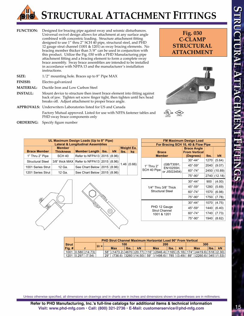
FUNCTION: Designed for bracing pipe against sway and seismic disturbances. Universal swivel design allows for attachment at any surface angle combined with concentric loading. Structure attachment fitting designed to use 1” thru 2” SCH 40 pipe, structural steel, and PHD 12 gauge strut channel (1001 & 1201) as sway bracing elements. No bracing member thicker than 3/8” can be used in conjunction with this product. Utilize the Fig. 030 with a PHD Manufacturing pipe attachment fitting and a bracing element to form a complete sway brace assembly. Sway brace assemblies are intended to be installed in accordance with NFPA 13 and the manufacturer’s installation instructions.
SIZE: 1/2” mounting hole Braces up to 8” Pipe MAX
FINISH: Electro-‐‑galvanized MATERIAL: Ductile Iron and Low Carbon Steel INSTALL: Mount device to structure then insert brace element into fitting against
back of jaw. Tighten set screw finger tight, then tighten until hex head breaks off. Adjust attachment to proper brace angle.
APPROVALS: Underwriters Laboratories listed for US and Canada Factory Mutual approved
Listed for use with NFPA fastener tables and PHD sway brace components only
ORDERING: Specify figure number
Fig. 030 C-‐‑CLAMP
STRUCTURAL ATTACHMENT
PHD Manufacturing, Inc.
Unless otherwise specified, all dimensions on drawings and in charts are in inches and dimensions shown in parentheses are in millimeters.
FUNCTION: Designed for bracing pipe against sway and seismic disturbances. Universal swivel design allows for attachment at any surface angle combined with concentric loading. Structure attachment fitting designed to use 1” thru 2” SCH 40 pipe, structural steel, and PHD 12 gauge strut channel (1001 & 1201) as sway bracing elements. No bracing member thicker than 3/8” can be used in conjunction with this product. Utilize the Fig. 030 with a PHD Manufacturing pipe attachment fitting and a bracing element to form a complete sway brace assembly. Sway brace assemblies are intended to be installed in accordance with NFPA 13 and the manufacturer’s installation instructions.
SIZE: 1/2” mounting hole. Braces up to 8” Pipe MAXFINISH: Electro-galvanizedMATERIAL: Ductile Iron and Low Carbon SteelINSTALL: Mount device to structure then insert brace element into fitting against
back of jaw. Tighten set screw finger tight, then tighten until hex head breaks off. Adjust attachment to proper brace angle.
APPROVALS: Underwriters Laboratories listed for US and Canada Factory Mutual approved. Listed for use with NFPA fastener tables and
PHD sway brace components onlyORDERING: Specify figure number
Fig. 030C-CLAMP
STRUCTURAL ATTACHMENT
FM Maximum Design Load For Bracing SCH 10, 40 & Flow Pipe
Brace Member
Brace Angle From Vertical
(Degrees) lbs. kN
1” Thru 2” SCH 40 Pipe
(GB/T3091, EN10255H,
or JISG3454)
30°-44° 1270 (5.64)
45°-59° 2040 (9.07)
60°-74° 2450 (10.89)
75°-90° 2740 (12.18)
1/4" Thru 3/8” Thick Structural Steel
30°-44° 900 (4.00)
45°-59° 1280 (5.69)
60°-74° 1570 (6.98)
75°-90° 1750 (7.78)
PHD 12 Gauge Strut Channel 1001 & 1201
30°-44° 1070 (4.75)
45°-59° 1440 (6.40)
60°-74° 1740 (7.73)
75°-90° 1940 (8.62)
UL Maximum Design Loads (Up to 8” Pipe) Lateral & Longitudinal Assemblies
Brace Member Member
Thickness Member Length lbs. kN Weight Ea. lbs. kg
1” Thru 2” Pipe SCH 40 Refer to NFPA13 2015 (8.96)
1.46 (0.66) Structural Steel 3/8” thick MAX Refer to NFPA13 2015 (8.96)
1001 Series Strut 12 Ga. See Chart Below 2015 (8.96)
1201 Series Strut 12 Ga. See Chart Below 2015 (8.96)
Strut Fig. #
PHD Strut Channel Maximum Horizontal Load 90° From Vertical
r l/r = 100 200 300 Max lbs. kN Max lbs. kN Max lbs. kN
1001 0.580 (14.73) 58” (1473.2) 4670 (20.77) 116” (2946.4) 1165 (5.18) 174” (4419.6) 518 (2.30) 1201 0.297 (7.54) 29” (736.6) 3260 (14.50) 59” (1498.6) 785 (3.49) 89” (2260.6) 345 (1.53)
STRUCTURE ATTACHMENT FITTINGS
FUNCTION: Designed for bracing pipe against sway and seismic disturbances. Universal swivel design allows for attachment at any surface angle combined with concentric loading. Structure attachment fitting designed to use 1” thru 2” SCH 40 pipe, structural steel, and PHD 12 gauge strut channel (1001 & 1201) as sway bracing elements. No bracing member thicker than 3/8” can be used in conjunction with this product. Utilize the Fig. 030 with a PHD Manufacturing pipe attachment fitting and a bracing element to form a complete sway brace assembly. Sway brace assemblies are intended to be installed in accordance with NFPA 13 and the manufacturer’s installation instructions.
SIZE: 1/2” mounting hole Braces up to 8” Pipe MAX
FINISH: Electro-‐‑galvanized MATERIAL: Ductile Iron and Low Carbon Steel INSTALL: Mount device to structure then insert brace element into fitting against
back of jaw. Tighten set screw finger tight, then tighten until hex head breaks off. Adjust attachment to proper brace angle.
APPROVALS: Underwriters Laboratories listed for US and Canada Factory Mutual approved
Listed for use with NFPA fastener tables and PHD sway brace components only
ORDERING: Specify figure number
Fig. 030 C-‐‑CLAMP
STRUCTURAL ATTACHMENT
PHD Manufacturing, Inc.
Unless otherwise specified, all dimensions on drawings and in charts are in inches and dimensions shown in parentheses are in millimeters.
FIRE PROTECTION& SEISMIC CATALOG

Refer to PHD Manufacturing, Inc.’s full-line catalogs for additional items & technical informationVisit: www.phd-mfg.com • Call: (800) 321-2736 • E-Mail: [email protected]
Unless otherwise specified, all dimensions on drawings and in charts are in inches and dimensions shown in parentheses are in millimeters.
16
STRUCTURAL ATTACHMENT FITTINGSST
RUCT
URA
L A
TTA
CHM
ENT
FITT
ING
S
UL Maximum Design Load
Pipe Size lbs. kN Weight Ea. lbs. kg
8” MAX (200) 2015 (8.96) 2.38 (1.08)
FM Maximum Design Load Beam Flange
Thickness
Brace Angle From Vertical
(Degrees)
X-Z Y-Z
Beam Flange
Thickness
Brace Angle From Vertical
(Degrees)
A-B
lbs. kN lbs. kN lbs. kN
3/8” Max
30°-44° 1040 (4.62) 970 (4.31)
3/8” Max
30°-44° 1150 (5.11) 45°-59° 1490 (6.62) 1370 (6.09) 45°-59° 1660 (7.38) 60°-74° 1800 (8.00) 2060 (9.16) 60°-74° 1990 (8.85) 75°-90° 2010 (8.94) 2300 (10.23) 75°-90° 2220 (9.87)
Fig. 035 SWAY BRACE BAR JOIST ADAPTER
FUNCTION: Sway brace adapter used to attach a PHD Manufacturing sway brace assembly to a steel bar joist or structural member of 3/8” maximum thickness. To provide a point of connection when drilling or welding is not allowed or not practical. Sway brace assemblies are intended to be installed in accordance with NFPA 13 and the manufacturer’s installation instructions.
SIZE: Braces up to 8” Pipe MAX Attaches to 3/8” thick MAX structural members When attaching to a structure thicker than 3/8”, please see PHD
Manufacturing Fig. 045. FINISH: Electro-‐‑galvanized MATERIAL: Ductile Iron INSTALL: Steel bar joist manufacturer'ʹs warranty requires attachment within 6"ʺof
chord panel point. Place on structural member with the flange contacting the back of the jaw. Tighten set screws finger tight, then evenly tighten until hex heads break off. Attached PHD structural attachment to Fig. 035 with the supplied attachment bolt, ensuring that the attachment bolt head bottoms out securely. Please note that the maximum load will be limited by the PHD Manufacturing structural attachment utilized with this adapter.
APPROVALS: Underwriters Laboratories listed for US and Canada Factory Mutual approved
Listed for use with NFPA fastener tables and PHD sway brace components only
ORDERING: Specify figure number
STRUCTURE ATTACHMENT FITTINGS
PHD Manufacturing, Inc.
Unless otherwise specified, all dimensions on drawings and in charts are in inches and dimensions shown in parentheses are in millimeters.
FUNCTION: Sway brace adapter used to attach a PHD Manufacturing sway brace assembly to a steel bar joist or structural member of 3/8” maximum thickness. To provide a point of connection when drilling or welding is not allowed or not practical. Sway brace assemblies are intended to be installed in accordance with NFPA 13 and the manufacturer’s installation instructions.
SIZE: Braces up to 8” Pipe MAX. Attaches to 3/8” thick MAX structural members. When attaching to a structure thicker than 3/8”, please see PHD Manufacturing Fig. 045.
FINISH: Electro-galvanizedMATERIAL: Ductile IronINSTALL: Steel bar joist manufacturer's warranty requires attachment within
6"of chord panel point. Place on structural member with the flange contacting the back of the jaw. Tighten set screws finger tight, then evenly tighten until hex heads break off. Attach PHD structural attachment to Fig. 035 with the supplied attachment bolt, ensuring that the attachment bolt head bottoms out securely. Please note that the maximum load will be limited by the PHD Manufacturing structural attachment utilized with this adapter.
APPROVALS: Underwriters Laboratories listed for US and Canada. Factory Mutual approved. Listed for use with NFPA fastener tables and PHD sway brace components only
ORDERING: Specify figure number
Fig. 035SWAY BRACE BARJOIST ADAPTER

Refer to PHD Manufacturing, Inc.’s full-line catalogs for additional items & technical informationVisit: www.phd-mfg.com • Call: (800) 321-2736 • E-Mail: [email protected]
Unless otherwise specified, all dimensions on drawings and in charts are in inches and dimensions shown in parentheses are in millimeters.
17
STRUCTU
RAL A
TTACH
MEN
T FITTING
SSTRUCTURAL ATTACHMENT FITTINGS
UL Maximum Design Load
Pipe Size lbs. kN Weight Ea. lbs. kg
8” MAX (200) 2015 (8.96) 3.10 (1.41)
FM Maximum Design Load
Beam Flange Thickness
Brace Angle From Vertical
(Degrees)
X Y
lbs. kN lbs. kN
3/8” Min. 1 1/4” Max.
30°-44° 1150 (5.11) 900 (4.00) 45°-59° 1800 (8.00) 1050 (4.67) 60°-74° 2230 (9.91) 1260 (5.60) 75°-90° 2460 (10.94) 1410 (6.27)
STRUCTURE ATTACHMENT FITTINGS
PHD Manufacturing, Inc.
Unless otherwise specified, all dimensions on drawings and in charts are in inches and dimensions shown in parentheses are in millimeters.
Fig. 045 SWAY BRACE STRUCTURAL ADAPTER
FUNCTION: Sway brace adapter used to attach a PHD Manufacturing sway brace assembly to a steel structural member of 3/8” minimum and 1 1/4” maximum thickness. To provide a point of connection when drilling or welding is not allowed or not practical. Sway brace assemblies are intended to be installed in accordance with NFPA 13 and the manufacturer’s installation instructions.
SIZE: Braces up to 8” Pipe MAX Attaches to 3/8” MINIMUM and 1 1/4"ʺ MAX thick structural members When attaching to a structure less than 3/8” thick, please see PHD
Manufacturing Fig. 035. FINISH: Electro-‐‑galvanized MATERIAL: Ductile Iron INSTALL: Place on structural member with the flange contacting the back of the
jaw. Tighten set screws finger tight, then evenly tighten until hex heads break off. Attached PHD structural attachment to Fig. 045 with the supplied attachment bolt, ensuring that the attachment bolt head bottoms out securely. Please note that the maximum load will be limited by the PHD Manufacturing structural attachment utilized with this adapter.
APPROVALS: Underwriters Laboratories listed for US and Canada Factory Mutual approved
Listed for use with NFPA fastener tables and PHD sway brace components only
ORDERING: Specify figure number
Fig. 045SWAY BRACESTRUCTURAL
ADAPTER
FUNCTION: Sway brace adapter used to attach a PHD Manufacturing sway brace assembly to a steel structural member of 3/8” minimum and 1 1/4” maximum thickness. To provide a point of connection when drilling or welding is not allowed or not practical. Sway brace assemblies are intended to be installed in accordance with NFPA 13 and the manufacturer’s installation instructions.
SIZE: Braces up to 8” Pipe MAX Attaches to 3/8” MINIMUM and 1 1/4" MAX thick structural members When attaching to a structure less than 3/8” thick, please see PHD
Manufacturing Fig. 035.FINISH: Electro-galvanizedMATERIAL: Ductile IronINSTALL: Place on structural member with the flange contacting the back of
the jaw. Tighten set screws finger tight, then evenly tighten until hex heads break off. Attach PHD structural attachment to Fig. 045 with the supplied attachment bolt, ensuring that the attachment bolt head bottoms out securely. Please note that the maximum load will be limited by the PHD Manufacturing structural attachment utilized with this adapter.
APPROVALS: Underwriters Laboratories listed for US and Canada. Factory Mutual approved. Listed for use with NFPA fastener tables and PHD sway brace components only
ORDERING: Specify figure number

Refer to PHD Manufacturing, Inc.’s full-line catalogs for additional items & technical informationVisit: www.phd-mfg.com • Call: (800) 321-2736 • E-Mail: [email protected]
Unless otherwise specified, all dimensions on drawings and in charts are in inches and dimensions shown in parentheses are in millimeters.
18
UL Maximum Design Load (8” Pipe Max) Fastener
Size lbs. kN Weight Ea. lbs. kg
1/2 (12.7) 2015 (8.96) 3.19 (1.45)
3/4 (19.1) 2015 (8.96) 3.19 (1.45)
Fig. 025 MULTI-‐‑FASTENER
ADAPTER
FUNCTION: Designed for bracing pipe against sway and seismic disturbances. Sway brace adapter used to develop a greater structural connection by providing multiple fastener attachment points. Adapter allows for 2 or 3 NFPA 13 approved fasteners to be used when one fastener is too weak to anchor a sway brace assembly to a structure. Sway brace assemblies are intended to be installed in accordance with NFPA 13 and the manufacturer’s installation instructions.
SIZE: 1/2” or 3/4” mounting holes Braces up to 8” Pipe MAX FINISH: Electro-‐‑galvanized MATERIAL: Low Carbon Steel, 2 X 2 X 1/4 Angle INSTALL: Attach to the structural surface as noted in NFPA13 fastener tables,
please note that the two outermost bolt holes should be used and the middle bolt hole should be used only in addition with both outer most bolt holes to ensure concentric loading. Attach a PHD Manufacturing structural attachment fitting to PHD Fig. 025 and follow the instructions provided with said fitting. The PHD structural attachment fitting can pivot around the mounting connection for adjustment to the desired brace angle. Please note that the maximum load will be limited by the PHD Manufacturing structural attachment utilized with this adapter.
APPROVALS: Underwriters Laboratories listed for US and Canada Listed for use with NFPA fastener tables and PHD sway brace components only Factory Mutual regards this device as part of the building structure
ORDERING: Specify figure number and fastener size
STRUCTURE ATTACHMENT FITTINGS
Unless otherwise specified, all dimensions on drawings and in charts are in inches and dimensions shown in parentheses are in millimeters.
*NOTE: All connecting fasteners are sold separately.
PHD Manufacturing, Inc.
Fig. 025MULTI-FASTENER
ADAPTER
FUNCTION: Designed for bracing pipe against sway and seismic disturbances. Sway brace adapter used to develop a greater structural connection by providing multiple fastener attachment points. Adapter allows for 2 or 3 NFPA 13 approved fasteners to be used when one fastener is too weak to anchor a sway brace assembly to a structure. Sway brace assemblies are intended to be installed in accordance with NFPA 13 and the manufacturer’s installation instructions.
SIZE: 1/2” or 3/4” mounting holes Braces up to 8” Pipe MAXFINISH: Electro-galvanizedMATERIAL: Low Carbon Steel, 2 X 2 X 1/4 AngleINSTALL: Attach to the structural surface as noted in NFPA13 fastener
tables. Please note that the two outermost bolt holes must be used. The middle bolt hole should be used only in conjunction with both outermost bolt holes to ensure concentric loading. Attach a PHD Manufacturing structural attachment fitting to PHD Fig. 025 and follow the instructions provided with said fitting. The PHD structural attachment fitting can pivot around the mounting connection for adjustment to the desired brace angle. Please note that the maximum load will be limited by the PHD Manufacturing structural attachment utilized with this adapter.
APPROVALS: Underwriters Laboratories listed for US and Canada. Listed for use with NFPA fastener tables and PHD sway brace components only. Factory Mutual regards this device as part of the building structure
ORDERING: Specify figure number and fastener size
STRUCTURAL ATTACHMENT FITTINGS
UL Maximum Design Loads Lateral & Longitudinal Assemblies
Pipe Size
Brace Size lbs. kN
Weight Ea. lbs. kg
2 1/2 (65) 1 (25) 655 (2.91) 2.09 (0.95)
3 (80) 1 (25) 655 (2.91) 2.19 (1.00)
4 (100) 1 (25) 655 (2.91) 2.84 (1.29)
2 1/2 (65) 1 1/4 (32) 655 (2.91) 2.02 (0.92)
3 (80) 1 1/4 (32) 655 (2.91) 2.12 (0.96)
4 (100) 1 1/4 (32) 655 (2.91) 2.77 (1.26)
FUNCTION: Designed for bracing pipe against sway and seismic disturbance. Versatile design allows for attachment at any angle and the ability to be used in a lateral or longitudinal bracing configuration. The pipe attachment component of a sway brace system used in conjunction with a PHD Manufacturing structural attachment fitting and joined together with a bracing pipe form a complete sway brace assembly. Sway brace assemblies are intended to be installed in accordance with NFPA 13 and the manufacturer’s installation instructions.
SIZE: Pipe size 2 1/2"ʺ thru 4"ʺ Schedule 10 thru 40 IP. Can use 1"ʺ or 1 1⁄4"ʺ Schedule 40 IP as sway bracing elements.
FINISH: Electro-‐‑galvanized MATERIAL: Low Carbon Steel INSTALL: Place attachment around pipe to be braced, positioning as needed, then
tighten clamping bolts and nuts. Insert bracing pipe into fitting against the pivot bolt and tighten each fitting set screw finger tight. Then tighten each set screw evenly until hex heads break off.
APPROVALS: Underwriters Laboratories listed for US and Canada Listed for use with NFPA and PHD sway brace components only
ORDERING: Specify figure number, brace pipe size, and sprinkler pipe size
Fig. 050 THREADLESS
PIPE ATTACHMENT
SWAY BRACE FITTINGS
PHD Manufacturing, Inc.
Unless otherwise specified, all dimensions on drawings and in charts are in inches and dimensions shown in parentheses are in millimeters.
FUNCTION: Designed to restrict the upward movement of activated fire sprinkler systems. Grips ring hanger, NOT THE NUT, and allows for fine tuning adjustments.
SIZE: Pipe size 3/4"ʺ thru 2"ʺ IP. FINISH: Powder Coating MATERIAL: Spring Steel INSTALL: Installs easily before or after pipe installation and without tools. Simply
clip Fig. 055 onto Fig. 141 ring hanger and run the hanger rod down to the bottom plate surface to ensure proper restraint.
APPROVALS: Underwriters Laboratories listed for US and Canada Listed for use with PHD Manufacturing, Inc. Figure 141 ring hangers only.
ORDERING: Specify figure number
Note: For use up to 2” pipe, one size fits all.
Fig. 055 SURGE
RESTRAINT
Fig. 055 (Pictured With Fig. 141)
SURGE RESTRAINT
PHD Manufacturing, Inc.
Unless otherwise specified, all dimensions on drawings and in charts are in inches and dimensions shown in parentheses are in millimeters.
Fig. 055SURGE
RESTRAINT
FUNCTION: Designed to restrict the upward movement of activated fire sprinkler systems. Grips ring hanger, NOT THE NUT, and allows for fine tuning adjustments.
SIZE: Pipe size 3/4" thru 2" IP.FINISH: Powder CoatingMATERIAL: Spring SteelINSTALL: Installs easily before or after pipe installation and without
tools. Simply clip Fig. 055 onto Fig. 141 ring hanger and run the hanger rod down to the bottom plate surface to ensure proper restraint.
APPROVALS: Underwriters Laboratories listed for US and Canada. Listed for use with PHD Manufacturing, Inc. Figure 141 ring hangers only.
ORDERING: Specify figure number
STRU
CTU
RAL
ATT
ACH
MEN
T FI
TTIN
GS

Refer to PHD Manufacturing, Inc.’s full-line catalogs for additional items & technical informationVisit: www.phd-mfg.com • Call: (800) 321-2736 • E-Mail: [email protected]
Unless otherwise specified, all dimensions on drawings and in charts are in inches and dimensions shown in parentheses are in millimeters.
19
(Lateral Brace) (Longitudinal Brace)
Fig. 031CLAMPING
PIPE ATTACHMENTContinued from page 13
Take advantage of PHD's Seismic Software to make ordering efficient simply follow these simple steps:
1st Visit www.phd-mfg.com2nd Click on the link “Seismic Bracing Calculator"3rd Enter your Customer Code*4th Enter Piping Specifications5th Pick Ticket for Quick Order
*Customer codes are assigned by your distributor
Customers like the easy to follow report that shows the calculations based on NFPA 13 2010 using UL approved product load limits.
• Brace Information • Brace Components• Fastener Information • Assembly Detail• Load Information
SWAY BRACE FITTINGS
SEISMIC SOFTWAREPHD SEISMIC BRACING CALCULATOR
SWAY B
RACE FITTIN
GS
VISIT: www.phd-mfg.comClick on Products - - Fire Protection/Seismic
You’ll find product details including: Function, Material, Finish, Ordering, and Approvals
Makes Ordering Easy!
