finalreportteam18 revised version - university of …€¦ · 5 impact of engineering solution ......
TRANSCRIPT

Final Report
Miniature Biaxial Testing Device
TEAM # 18
Leah Y. Pruzinsky Stephany Santos Christine Vogel
Project for Dr. Wei Sun, Ph. D.
Client Information:
Assistant Professor of Biomedical Engineering & Mechanical Eng. 207 Bronwell Building
University of Connecticut, Storrs, CT 06269-3139
Phone: (860)486-0369, Fax: (860)486-2500
Email: [email protected]
Website: http://tml.engr.uconn.edu/

Team 18 Pruzinsky, Santos, Vogel Page
1
Table of Contents
1 Introduction …................................................................................................................................ 1.1 Background (client and disability) …............................................................................
1.2 Purpose of the project ….................................................................................................
1.3 Previous Work Done by Others .....................................................................................
1.3.1 Product ...........................................................................................................
1.3.2 Patent Search Results .....................................................................................
1.4 Map for the rest of the report .........................................................................................
2 Project Design ................................................................................................................................ 2.1 Introduction .................................................................................................................... 2.2 Optimal Design ............................................................................................................... 2.2.1 Objective ....................................................................................................... 2.2.2 Subunits ......................................................................................................... 2.3 Prototype…………………………………………………………………………….. 2.3.1 Motor mounts…………………………………………………………….. 2.3.2 LabVIEW………………………………………………………………… 2.3.3 Encoders and encoder wiring……………………………………………. 2.3.4 Tissue specimen………………………………………………………….. 2.3.5 Saline bath………………………………………………………………... 2.3.6 Load cells………………………………………………………………… 2.3.7 Motor driver and motor wiring…………………………………………… 2.3.8 Two-photon microscope set-up…………………………………………... 3 Realistic Constraints ...................................................................................................…............... 4 Safety Issues ...................................................................................................….......................... 5 Impact of Engineering Solution ..........................................................................................……… 6 Life-Long Learning ...................................................................................................…................ 7 Budget
7.1 Budget............................................................................................................................
8 Team Members Contributions to the Project ................................................................................ Team member: Leah Pruzinsky ........................................................................................... Team member: Stephany Santos ......................................................................................... Team member: Christine Vogel .......................................................................................... 9 Conclusion ..................................................................................................................................... 10 References .................................................................................................................................... 11 Acknowledgments ....................................................................................................................... 12 Appendix .................................................................................................................................... 12.1 Updated Specifications ...............................................................................................
2
2
4
4
5
5 6
6 6 11 12 13 23 24 25 26 28 28 29 29 32 33 34 35 36 37 38 40 41 42 43 43

Team 18 Pruzinsky, Santos, Vogel Page
2
12.2 Datasheets.................................................................................................................... 12.2.1. Hybrid linear actuator/motor datasheet....................................................... 12.2.2. Encoder specifications ................................................................................. 12.2.3 Load cell spec sheet……………………………………………………….
Abstract
Our client is in need of a miniature biaxial testing device for small, thin tissue samples. A biaxial testing device applies tensile and compressive forces to a small tissue specimen in two-dimensions. Currently, biaxial testing devices accommodate larger tissue samples (~100mm2) than our client would like to test. Small tissue samples are difficult to secure in the current biaxial machine setup and tear easily.
The motivation for a smaller device is having the option to transport it and have a compact device. It is intended for transportation to the two-photon microscopy lab where the tissue microstructure may be viewed under the microscope. The device will be compatible with two imaging instruments: a basic video camera to track tissue movement, and the two-photon microscope previously mentioned.
In general, biaxial testing is desirable as an experimental determination of soft tissue mechanical properties. By tracking the deformation of the sample due to cyclic loading characteristic material properties can be extracted. This information is important for many applications, and in the case of our client, cardiac soft tissues are of interest. Tissue material properties can be used in improving the design of devices such as cardiac stents and bioprosthetic valves, as studied in the Tissue Mechanics Lab (TML). Material properties can also be inputted into finite element analysis models. Here, computational modeling can be used to evaluate current cardiac devices.
The device will be contained within a 7.25 square inch area and three inch height so it fits beneath the two-photon microscope. Two motors are used and linear motion translated to the tissue specimen to pull the sample in two directions. Two load cells are also used to measure the forces exerted on the tissue in the x and y directions. Testing is observed via the digital video camera, and the tissue microstructure may be observed before or after testing. During all testing, the sample is contained in a cross-shaped saline bath. The end product will be a compact biaxial machine, and it will also be one of a kind. The device will have good precision and be able to obtain results that are comparable with existing technology.
1. Introduction and Overview
1.1 Background
This project is for Dr. Wei Sun who is an Assistant Professor for the Mechanical Engineering and Biomedical Engineering departments at the University of Connecticut. His research focuses on tissue mechanics with both experimental work and computational models to
44 44 45 46
Team 18 Pruzinsky, Santos, Vogel Page
3
further the understanding of soft tissue behavior. Specifically, the tissue mechanics laboratory (TML) is concerned with cardiac mechanics. The TML generally examines soft tissues such as the myocardium, pericardium, heart valve leaflets, and heart valve membranes; however, similar tests could be performed on any soft tissue type. Changes in tissue microstructure as humans age often contribute to tissue degradation and mechanical failures which play a large role in human diseases and deaths. Heart valve replacement devices could be assessed before implantation by creating 3-dimensional models which replicate the performance of the devices in the body. In this way, the ability of the devices to function properly could be tested without endangering patients’ lives. Three-dimensional models could also be used to visualize the smooth muscle contractions of the myocardium. There have been limitations in models previously synthesized to evaluate the myocardium contraction mechanism. Three-dimensional models are also useful for surgeons who need to know the exact locations to make incisions in tissues. The mechanical properties of various tissues are also essential to the surgeons’ knowledge in that the surgeon needs to know how much force is required to make an incision and how the tissue will respond to manipulations. Accurate knowledge of tissue structure will lead to the creation of improved implantable devices for disease treatment. The miniature biaxial testing device will be used by Dr. Sun and his assistants in his laboratory. The device will also be portable in order to test soft tissues and simultaneously image a specimen with a two-photon microscope. All of the work with the instruments will be done on the Storrs University campus.
Uniaxial tensile tests prove insufficient for evaluating the deformation of soft tissues. The tissue is stretched in one direction, and there is no tension hindering the movement of the sides of the tissue that are not attached to the uniaxial testing machine. Stresses from multiple directions are often simultaneously applied to tissues in the body. Biaxial testing devices provide a more realistic means of evaluating the mechanical properties of tissues by applying forces to a specimen in two orthogonal directions. Additionally, the two-dimensional results can be extrapolated to predict the tissue’s three-dimensional response.
To track the tissue mechanics using current biaxial devices, four markers are placed in the center of the sample at the corners of a small square region. The stress and strain measurements in this region are considered homogeneous due to its small size. A thin tissue sample is mounted in a phosphate buffered saline bath and stretched along two perpendicular axes that are aligned with the preferred fiber orientation and the cross-fiber direction. The biaxial device in Dr. Sun’s lab currently uses pairs of hooks to anchor the tissue sample, and the hooks are attached to sutures which are looped around pulleys. Load cells, a transducer, and four motors are used to move the tissue, and a CCD camera is used to capture an image.
A CCD camera is placed above the bath to capture the deformation of the markers. The tissue sample is subjected to preconditioning before testing begins. Preconditioning involves applying small loading and unloading cycles to the tissue specimen. Seven stress protocols have previously been used to comprehensively document the tissue’s stress-strain relationship. The protocols allow for uneven ratios of force from two perpendicular directions to be exerted on the specimen.
Two-photon microscopy is a fluorescence non-linear imaging technique which allows for deep tissue imaging. Two-photon microscopy will penetrate tissue specimens up to 1 mm

Team 18 Pruzinsky, Santos, Vogel Page
4
depths. Biological tissues strongly scatter light. Nonlinear signal generating systems make it possible to capture high-resolution, deep penetrating images. A laser emits pulses of near-infrared light which passes through three lenses before reaching the specimen. The two-photon excited fluorescence can be collected using epi- and/or trans-collection mode with photomultiplier tubes (PMTs).
1.2 Purpose of the project
The purpose of the project is to design a miniature biaxial testing device for soft
connective tissues. The device must be small in order to fit underneath a two-photon microscope. A method of analyzing the orientation of the microfibers viewed through the two-photon microscope will be devised once the biaxial machine is assembled. The project also involves the design of a type of cookie-cutter mold to cut the tissue into a desirable shape for mounting in the biaxial testing machine.
Small tissue samples have been tested using the device currently located in the Bronwell
building; however, the tissue samples are prone to tearing when they are stretched due to the difficulty of attaching hooks to the specimen. A different means of gripping the tissue is needed. It is hard to attach the same number of hooks used for average-sized specimens onto small tissue samples. Four hooks are attached to each side of the average-sized specimens.
Soft tissues exhibit non-linear stress-strain behavior, high elasticity and mechanical
anisotropy. Soft tissues are also generally characterized as incompressible. Due to their complexity, it has been a challenge to construct accurate models for their behavior. Data from biaxial testing experiments can be used to identify material parameters for 3-D constitutive models. These models can be used to visualize the tissue deformation in vivo and can be used for predicting the functionality of bio-prosthetics as an example. Understanding a tissue’s mechanical properties by creating accurate models will be critical for the design of implantable devices. Another application of this device, or the knowledge collected from it, may be for tissue engineering. Here a scaffold to support cell growth will depend on the strength and mechanical cues of its environment.
1.3 Previous work done by others
A relatively small group within academia accounts for the majority of work within the
area of biaxial testing of soft tissue mechanics when specifically pertaining to cardiac mechanics. Dr. Wei Sun is highly regarded amongst this group and is supported extensively by national funding agencies to continue his research. Dr. Sun previously has worked with Dr. Sacks (Pittsburgh) on studying mechanical properties of biological tissues using multiaxial testing apparatus [1]. Additionally, the graduate students in the tissue mechanics laboratory continue to use biaxial testing to supplement their research work. Biaxial testing has been used to input material properties into computational models for simulating cardiac mechanics. Specifically, Dr. Sun’s research group focuses on applying this knowledge to evaluate medical device design such as stents, and bio-prosthetic valves.

Team 18 Pruzinsky, Santos, Vogel Page
5
Four undergraduate WPI students designed a miniature biaxial testing device for compliant tissue in 2005. Dr. Kristen Billar of Worchester Polytechnic Institute was their advisor. The design team made a four-axis planar biaxial testing device that fit into a small space. The device used screw-driven slides and two rotational force transducers as described in [2]. A motion controller board and filter system were purchased from National Instruments. A stepper motor was also chosen for the design. The sample was mounted in a saline bath with fishhooks and sutures.
1.3.1 Products
The company ADMET manufactures a biaxial test system with two orthogonal actuators. The machine uses sutures to connect the specimen to the load cells and actuators. The biaxial testing design has the option of using clips to hold the specimen as well.
Zwick is an Italy based company that also makes a biaxial testing device called mediX0.1. Their device uses pulleys and sutures to suspend the specimen. The minimum sample size that the device can accommodate is 10 mm by 10 mm. Our client desires a biaxial testing system which can test a 5 mm by 5 mm specimen so the mediX0.1 biaxial test machine does not meet our client’s small specimen specification. The Zwick biaxial test machine also uses four high-resolution linear drives, which is similar to our senior design team’s proposed device in that it contains four linear actuators.
The company Instron produces a BioPuls low-force planar-biaxial soft tissue system with four fatigue-rated actuators. The actuators have a 120 mm stroke per axis. The company sells corrosion resistant grips as an option for securing the specimen in the machine. Instron also sells line contact grips, which are a mechanical clamp type of grip, as an alternative option. The device’s bath is approximately 12.5 inches by 12.5 inches and 1.42 inches in height.
ElectroForce, a division of BOSE is a popular supplier of mechanical testing devices.
This division has a planar biaxial testing device from their TestBench systems, and is capable of performing both uniaxial and biaxial tests. The BOSE machine includes four linear motors, X and Y load cells, a heated saline bath and a digital camera contained on a 36 x 36 in base.
1.3.2 Patent Search Results
Ghosh and Tushar K. patented a biaxial testing device which uses clamping systems to grip textile and membrane material samples in 1999. The clamping systems are oriented along an X-axis and a Y-axis which are orthogonal to each other. The device was designed to analyze the stress-strain behavior of textile fabrics since these materials exhibit nonlinear and complex stress-strain relationships. The device has spaced-apart segmented clamping systems interconnected by pantographs so that the clamps can contract and extend with respect to each other. The design aims to allow strain to occur naturally near the anchored edges and minimize the boundary effects of the clamped edges as claimed in [3].

Team 18 Pruzinsky, Santos, Vogel Page
6
The inventors Brodland and Wayne patented a multiple point attachment system for specimen loading or deformation according to [4]. The device can have either two carriers on opposite sides of the specimen for uniaxial testing or four carriers oriented at 90 degrees to each other around the specimen for biaxial testing. Any number of carriers can be used in this patented device. The carriers are connected to motion control and load measuring systems. Flexible fingers attached to the carriers grip the specimen. The fingers are flexible in directions in the plane of the specimen but are taut when they subjected to tensile or compressive forces.
1.4 Map for the Rest of the Project
The remainder of the report outlines the specific details of our senior design project, the miniature biaxial testing device. Our three alternative designs will be explained and reviewed. The final design was synthesized from these preliminary designs. The report then continues with the salient characteristics of this optimal design. The constraints which challenge our project will be addressed. Furthermore, we will explain safety considerations of our device, the impact it will have as an engineering solution, and the life-long learning that is involved in its creation and use. Each team member has provided a summary of their responsibilities. The report concludes with references from outside sources and acknowledging people who have contributed to the success of our project thus far. Finally, any additional information such as data sheets for components, a detailed budget and specifications can be found in the appendix section.
2. Project Design
2.1 Introduction
2.1.1 Given Constraints
The client desires the biaxial device to be portable and functional at the two-photon
microscope in the Pharmacy Building on the University of Connecticut Campus. The dimensions of the workspace underneath the microscope are described in Fig. 1. The alternative designs proposed in this report all must fit into the given constraints as well as provide solutions to all problems and specifications given by the client. Each of the three team members has proposed an alternative design and built it using SolidWorks software. The optimal design was chosen by an agreement between the team members and Dr. Sun. It was also possible to combine separate components of each alternative design and combine them to make one optimal prototype design.

Team 18 Pruzinsky, Santos, Vogel Page
7
Figure 1. Dimensions of the experimental area at the two-photon microscope.
2.1.2 Alternative Design 1
Figure 2. Alternative Design 1 Solidworks image which includes the saline bath, arms, linear
actuators, load cells, specimen, mirror and base.

Team 18 Pruzinsky, Santos, Vogel Page
8
Figure 1 shows the components of alternative design one created by Christine Vogel. The linear actuators are colored blue in the figure and the motors are red. The load cells are orange, the mirror is a maroon color, and the saline bath is green. A base rests under the bath that will be screwed into the holes of a lab bench. The arms are grey and are composed of three connected bars. The direction of the arm changes at each connection. The arms extend into the green saline bath.
Microvascular clamps are used to grip each side of the specimen. One clamp is positioned on each side of the tissue sample, which is cruciform-shaped. Sutures are tied to hooks which are connected to the rods going through the clamps. The sutures loop around each arm and are inserted into slots cut in the arms. The ends of the arms are submerged in saline water filling the cross-shaped bath. The cross-shaped bath saves space for the linear actuator and motor mounts. The bath also mimics the shape of the specimen. The cruciform-shaped specimen with the attached microvascular clamps is shown in Fig. 2.
Figure 3. An enlarged picture of the specimen and clamps located in the center of the bath
Load cells are attached to the arms above the bath and linear actuators are attached to the other side of the load cells. The actuators control the arms’ motion, which is perpendicular to the edge of the specimen closest to each arm. The four actuators are powered by motors. Mounts support the actuators and motors. The mounting pieces for the linear actuators include mounting clamps and brackets, and a rod end. A rail connects the linear actuator and the motor. When the rotational motion of the load cell is converted to linear motion the rail pushes on the arm, and this in turn applies a tensile force to a side of the specimen.
A camera is positioned in the device to capture the reflection from a mirror located above the specimen. The mirror is located directly above the specimen and angled so that the markers on the specimen are seen through the camera’s lens. A hole in the center of the mirror allows the user to view the specimen through the lens of a 2-photon microscope. The hole allows a user to see the microstructure of the specimen as it is biaxially tested through the two-photon microscope. The biaxial testing device is placed below the two-photon microscope.

Team 18 Pruzinsky, Santos, Vogel Page
9
2.1.3 Alternative Design 2
Figure 4. Profile and top views of alternate design two, designed by Leah Pruzinsky
Figure 4a. Tissue clamping mechanism
The biaxial testing device is setup on a base plate with screw holes for anchoring to any site that it is transported to. Tissue samples to be tested with this machine are contained in a small square saline bath pictured in the center of the design. Inside the bath is the sample that will be cut into a cross shape. Four motors (in green) will be used to pull the tissue in four directions, negative and positive x and y (planar, biaxial). The tissues are introduced to force by loading cycles which stretch the tissue. Each motor produces a circular motion, which is translated into a uniaxial linear movement by the linear actuator (in purple). A load cell is placed on two of the motors, one which pulls in the x direction the other in the y. An arm (light blue) is then connected at a ninety degree angle to this actuator to connect the tissue sample to the linear pulling motion. The four motors are arranged such that space is optimized. This is done by placing each motor along the edge of the saline bath, with an arm connected to the sample which is at a ninety degree angle to the linear actuator. This is contrasted to a design in which the motor/ actuator/ arm connection does not change directions. That design takes up more space, which was an important consideration in our design, because the client requires a device which is compact and transportable.

Team 18 Pruzinsky, Santos, Vogel Page
10
Another important consideration to our design was the clamping mechanism. Previously, sutures or hooks have been more commonly used as a mechanism for attaching the tissue sample for testing. However, due to the decreased size of our device, and therefore specimen size a new method is required. The clamping mechanism in this design is such that the faces in direct contact to the sample are lined with a gritted sandpaper to grip the tissue. Additionally, this mechanism has adjustable screws to tighten the clamps onto the tissue and is pictured in Figure 4a.
Lastly, drivers and controls for the motors are not included in this initial design. This is because the NI hardware and software which will perform these necessary functions are already in the possession of the client and will be easily coupled to our device upon assembly.
2.1.4 Alternative Design 3
Figure 5. The third alternative design prototype. Designed by Stephany Santos.
For this design, the tissue specimen will be held by means of a micro clamp that will prevent the tissue from slipping as well as provide minimal damage to the tissue. The clamps will be attached to the motor shafts, which are indicated in the above image by the color yellow. The inner cross-shaped area made by the enclosed tracks will be filled with the saline solution to place the specimen. These shafts are what provide the linear deformation to the tissue. Each shaft is individually controlled by a Hybrid Linear Actuator Motor that causes the stretch-contract motion. The hybrid linear actuator motor is designed by HaydonKerk and converts motion from an internal rotary motor into simple uniaxial linear motion. The hybrid motors are placed on top of each track, and controls the motion of the axis counterclockwise to its fixed base location.

Team 18 Pruzinsky, Santos, Vogel Page
11
On an outer lip adjoined to the X2 axis, there will be the base for the CCD Camera. This base is a swivel cylinder base provided by Jergens, Inc. This swivel apparatus will allow for vertical, horizontal, and rotational adjustment of the CCD camera.
Directly diagonal to the camera mount, there is a shaft supporting the mirror clip. The mirror will be more adjustable than the camera, and will thereby allow motion in all degrees of freedom. The key is for the mirror to accurately reflect the specimen deformation, as well as have a small hole in an appropriate location that will allow for a photon beam from the fluorescent microscope to pass through. The design of the bath is approximately 7 inches in width and 9 inches in length. The height varies depending on the device structures, however there is a planar surface at the center that is less than the 3 inches as required by the dimensions of the two-photon light microscope.
The motors will be controlled by NI LabVIEW interface hardware by portable laptop at the experiment site. The data will be able to be collected at this location for convenience as well.
2.2 Optimal Design
The selected optimal device is based on Alternate Design 3, but has a few key changes by input from Dr. Sun and the team members. The full updated design can be seen in Fig. 6 below.
Figure 6. Solidworks assembly of optimal design. This structure was selected for its ease in portability and compartmentalized features. The
only significant difference of this design is the location of the hybrid motor stepper linear actuators. The motors were shifted to reduce arm length and torque, resulting in better accuracy from the acquired data. The short arm length is a major change from all three of the alternate designs.

Team 18 Pruzinsky, Santos, Vogel Page
12
Another major change is the location and type of load cell. Originally a bridge load cell was discussed in the third alternate design; however a Futek beam load cell that also acts as a clamp-to-arm connector was selected for the final design. These components will be further described in the next section.
The specimen will be held by small fish hooks that will prevent the tissue from slipping
as well as provide minimal damage to the tissue. Two hooks will be attached to each side of the specimen with the use of tweezers. Sutures will be tied through a hole in each of the hooks and the suture will be attached to the motor shafts, which are yellow in the above image. The inner cross-shaped area made by the enclosed tracks will be filled with the saline solution to place the specimen. These shafts are what provide the linear deformation to the tissue. Each shaft is individually controlled by a Hybrid Linear Actuator Motor that causes the stretch-contract motion.
Our client decided that it would be best to eliminate the mirror from our design. Both
imaging modalities, the two-photon microscope and the CCD camera, will no longer be used simultaneously as the device is tested. The reasoning for this decision is that the two-photon microscope operates in the dark and it would be difficult to track the marker positions with the CCD camera and mirror in a dark room. The mirror was included in the previous design to accurately reflect the specimen deformation, and allow for a photon beam from the fluorescent microscope to pass through a small hole in the mirror, so that both imaging techniques would be employed at the same time.
The design of the bath is more compact in which it has a constant 7.25 inch side length.
The height varies depending on the device structures; however, there is a small region at the device’s center that is less than the 3 inches as required by the limited space under the two-photon light microscope.
Furthermore, another convenience is the ability to use the four outer squares as storage
containers for cords and cables to the load cell, motor, and power strips. By coiling the cords here, it minimizes space taken at the experimental location, as well as allows for faster setup and removal.
As with the original design, the motors will still be controlled by NI LabVIEW interface hardware by portable laptop at the experiment site. The data will be able to be collected at this location for convenience as well.
2.2.1 Objective
The objective our project is to design, assemble and make functional this miniature biaxial testing device which will produce comparable results to previous tests performed with the current and larger sized biaxial device. A small sized device will allow for transportation to the two-photon microscopy lab so that two imaging techniques will be used to gather data during testing. Our device must be small enough to fit in this area. Additionally, it is required to work using the existing equipment owned by the client. This includes drives and power to operate the motors, and software which can collect and analyze the results. LabVIEW coding is necessary to

Team 18 Pruzinsky, Santos, Vogel Page
13
control the motors and obtain feedback on the position of the encoders. Finally, an aim of the project is to create a user-friendly device which is convenient for those who will implement the device into their research work. Here, we discuss the components of our device which allow us to fulfill these objectives.
2.2.2 Subunits
Device Base
For this device, the base has two constituents: an outer frame and an inner bath container. The outer frame is what holds all the components in a configuration compact enough to allow for portability. The frame has a side length of 7.25 inches and is made of aluminum from the machine shop. The aluminum will be able to provide enough support to the motors without any deformation or excessive fatigue. It is very durable in numerous environments which is key with respect to device portability. Furthermore, the device will be exposed to biological tissues, and will therefore need to be sterilized for health and safety measures. Aluminum is not a very porous material, and will therefore be able to be easily sterilized with a topical disinfect. Additionally, there is a high possibility that some of the saline solution may come into contact with the outer frame by means of human error or device malfunction. The frame therefore needs to be able to withstand this medium without fear of quick corrosion.
For the inner bath container, the chosen material will be Plexiglas, a clear, durable
plastic. This material is currently used in the biaxial machine located in Dr. Sun’s lab. The material insulates the bath better than metal would, and is easy to clean with a disinfectant. The bath will be CNCed from one piece of plexiglass and to prevent the bath from leaking. The saline solution has a composition very similar to that of bodily fluids, so therefore, the selection of this material to hold the solution ensures that there will be minimal corrosion and damage to the base. The reasons mentioned above for the selection of material for the outer base also apply for the inner container. The inner bath is designed to have maximum capacity of approximately 333 mL of solution when empty.
Aluminum pieces were obtained from Pete to machine the base of our machine; a 7.25 square inch bottom plate and four surrounding walls which were milled down to size. A sketch for the components was created and shown below. The parts of the aluminum base consist of the following aluminum pieces (length x width x height): 7.25 x 7.25 x .25”, two 7.25 x 1.5 x .125”, and two 7 x 1.5 x .125”.

Team 18
Figure 7. Miniature biaxial testing device base Holes were drilled in the base to be able to screw it into the Thorlabs tabletop in the Tissue Mechanics Lab. The distances between the holes on the tabletop were obtained from the website. Additionally, a picture of the tabletop underneath the 2with the dimensions indicated.
The motor to be used is the Haydon Size 8 Hybrid Steppseries. This motor is called hybrid because it combines the functionality of a rotational motor and linear actuator into one compact device. The device is programmable using LabVIEW software and, as seen in Fig. 4, the output of the device is strictly linear motion. The wiring of the device is bipolar and operates at 5VDC, while the current/phase is 0.42 A, both of which are sufficient parameters for the biaxial test. The selected stroke for typical samples, will be an excess stretch length.
For the device, there will be four motors that will be mounted atop the edges of the sali
bath, as depicted in Fig. 8. The motors will be paired with the motor directly opposite same axis to provide equal tensiondeformation is true to the assumptions made regarding homogeneous tissue samples and true
biaxial testing.
Pruzinsky, Santos, Vogel
Figure 7. Miniature biaxial testing device base
Holes were drilled in the base to be able to screw it into the Thorlabs tabletop in the e distances between the holes on the tabletop were obtained from the
website. Additionally, a picture of the tabletop underneath the 2-photon microscope was taken
Motor
The motor to be used is the Haydon Size 8 Hybrid Stepper Motor Linear Actuator, 28000 series. This motor is called hybrid because it combines the functionality of a rotational motor and linear actuator into one compact device. The device is programmable using LabVIEW software
put of the device is strictly linear motion. The wiring of the device is bipolar and operates at 5VDC, while the current/phase is 0.42 A, both of which are sufficient parameters for the biaxial test. The selected stroke size for the motor will be 0.5 for typical samples, will be an excess stretch length.
For the device, there will be four motors that will be mounted atop the edges of the sali. The motors will be paired with the motor directly opposite
tension on each axis. This is important in ensuring that the recorded deformation is true to the assumptions made regarding homogeneous tissue samples and true
Page 14
Holes were drilled in the base to be able to screw it into the Thorlabs tabletop in the e distances between the holes on the tabletop were obtained from the
photon microscope was taken
er Motor Linear Actuator, 28000 series. This motor is called hybrid because it combines the functionality of a rotational motor and linear actuator into one compact device. The device is programmable using LabVIEW software
put of the device is strictly linear motion. The wiring of the device is bipolar and operates at 5VDC, while the current/phase is 0.42 A, both of which are sufficient
inches, which
For the device, there will be four motors that will be mounted atop the edges of the saline . The motors will be paired with the motor directly opposite on the
. This is important in ensuring that the recorded deformation is true to the assumptions made regarding homogeneous tissue samples and true

Team 18 Pruzinsky, Santos, Vogel Page
15
Figure 8. (A) The Hybrid Stepper Motor in extended position. The rainbow colored rods on top
are the connections to the cable. (B) An aerial view of the motors on top of the saline base and
frame.
US Digital Encoders
Encoders are mounted on the back of the motors. A SolidWorks assembly of the motor
and encoder is shown in Fig. 9. A picture of an encoder is shown in Fig. 10 below as well. The
rotary encoders are miniature in size and provide digital quadrature encoder feedback. The
encoders operate by sensing pulses from different phases and picking up on the angle of the
motor shaft. It is an E4P series encoder, and can be connected to the motor driver with a (high
retention 4-conductor snap-in polarized 1.25 mm pitch) connector. These connectors can be
removed from the encoder and snapped back in place.
Figure 9. SolidWorks assembly of motor and encoder.
A B

Team 18
The motor mount design consists of a top rightpieces that support this top piece. Specifically, the bottom pieces are made of 2 in. angle aluminum (0.125in thick). The team cut 8 about ¾ in. wide pieces of this aluminum material. The procedure uses two of these pieces screwed into the base and the motor mount top to suppit. A picture of these finished pieces is shown in
Figure 11. A side view of the motor mounting pieces.
Futek beam load cells were chosen selected read forces up to 0.25 lbs. The load cell will 2 N, which equates to a reading of 181.4 grams.applied to the load cell. The maximum load able to be withstood by a thin, smooth tissue sais approximately 150 grams, as tested in Dr. Sun’s Tissue Mechanics Lab.
Pruzinsky, Santos, Vogel
Figure 10. US Digital encoder.
Motor Mounts
The motor mount design consists of a top right-angle aluminum piece and two rightthis top piece. Specifically, the bottom pieces are made of 2 in. angle
aluminum (0.125in thick). The team cut 8 about ¾ in. wide pieces of this aluminum material. The procedure uses two of these pieces screwed into the base and the motor mount top to suppit. A picture of these finished pieces is shown in Fig. 3.
Figure 11. A side view of the motor mounting pieces.
Load Cells
Futek beam load cells were chosen for the miniature biaxial testing device.25 lbs. The load cell will function correctly up to a maximum load of
2 N, which equates to a reading of 181.4 grams. The load cell may break if loads above 2N are The maximum load able to be withstood by a thin, smooth tissue sa
150 grams, as tested in Dr. Sun’s Tissue Mechanics Lab.
Page 16
angle aluminum piece and two right-angle this top piece. Specifically, the bottom pieces are made of 2 in. angle
aluminum (0.125in thick). The team cut 8 about ¾ in. wide pieces of this aluminum material. The procedure uses two of these pieces screwed into the base and the motor mount top to support
for the miniature biaxial testing device. The load cells a maximum load of
The load cell may break if loads above 2N are The maximum load able to be withstood by a thin, smooth tissue sample

Team 18
Dummy load cells were made to mount the tissue with the pulley system. Dummy load
cells with the same dimensions as the actual load cells were made in the machine shop. The dummy load cells are made of 304 steel. Currently, the team has a total of three load cells available for use. A picture of the machined dummy load cells and a picture of the real load cell are shown below.
Figure 13. The be
Pulleys are used to attach threads from the specimen to the load cells. The pulleys are
small, black pieces that were made in the machine shop.
pulley system setup.
Figure 14. Pulley system attached to a load cell.
The “micro pulley” is 10mm in width which is the largest parameter on the component.
The shaft is a 3/32” stainless steel shoulder bolt purchased from McMaster, which should not
rust when submerged in water. The pulley is made of Dacron plastic, which is waterproof, and
Pruzinsky, Santos, Vogel
Dummy load cells were made to mount the tissue with the pulley system. Dummy load cells with the same dimensions as the actual load cells were made in the machine shop. The
my load cells are made of 304 steel. Currently, the team has a total of three load cells available for use. A picture of the machined dummy load cells and a picture of the real load cell
Figure 12. Dummy load cells.
Figure 13. The bending beam load cell by Futek.
Pulley system
Pulleys are used to attach threads from the specimen to the load cells. The pulleys are
small, black pieces that were made in the machine shop. Figure 14 shows a Dacron
ure 14. Pulley system attached to a load cell.
The “micro pulley” is 10mm in width which is the largest parameter on the component.
The shaft is a 3/32” stainless steel shoulder bolt purchased from McMaster, which should not
. The pulley is made of Dacron plastic, which is waterproof, and
Page 17
Dummy load cells were made to mount the tissue with the pulley system. Dummy load cells with the same dimensions as the actual load cells were made in the machine shop. The
my load cells are made of 304 steel. Currently, the team has a total of three load cells available for use. A picture of the machined dummy load cells and a picture of the real load cell
Pulleys are used to attach threads from the specimen to the load cells. The pulleys are
Dacron pulley in the
The “micro pulley” is 10mm in width which is the largest parameter on the component.
The shaft is a 3/32” stainless steel shoulder bolt purchased from McMaster, which should not
. The pulley is made of Dacron plastic, which is waterproof, and

Team 18 Pruzinsky, Santos, Vogel Page
18
has high abrasion resistance. The pulley is screwed into a small bent metal piece which is
attached to the load cell via a screw. A nut is placed on the other side of the load cell to hold the
assembly in place.
Tissue Specimen
A bovine pericardium tissue specimen was used to test the biaxial testing device. The tissue specimen will be a part of the circulatory system located near or around the heart. For instance, the tissue specimen may be a leaflet from a heart valve or a small section of the aorta. The tissue specimen is cut into a square piece that is between 5 mm2 and 10mm2 in surface area. Four graphite markers are attached to the specimen with superglue and a pin. The markers are arranged on the corners of a small square in the center of the tissue.
Specimen Attachment
The specimen will be attached to threads via hooks. The hooks are very small which agrees with the sample size. Two hooks are attached to each side of the tissue sample. The holes should be no more than 1 mm from the edge of the tissue specimen. In the case that the threads are tied directly to the specimen, a needle will be used to poke holes through the specimen and thread the string through the specimen. For the hook design, the suture will be tied through small holes in the hooks. One thread is used for the two hooks on one side of the specimen. The thread is looped around the black plastic piece in the pulley system design. Size 18 fishing hooks are used.
Saline Bath
The bath is filled with nine percent per volume saline solution. Five liters of this solution are made. Small amounts of four different chemicals will be added to one liter of water and mixed into the water with a hot plate and magnetic stirrer. Salt, or sodium chloride, is the main chemical added to the solution. Specifically, 40.004 g of NaCl, 1.006 g of KCl, 0.500 g of MgCl26H20, and 0.280 g of NaH2PO4 will be measured and added. Four liters of water is then mixed with the stirred one liter solution of chemicals and water, and the entire solution volume is put into a pitcher. This solution is then poured into the center of the biaxial testing device’s saline bath until the device’s four pulleys are below the water level. The saline solution is maintained at approximately 37 degrees Celsius to simulate human body temperature by using a heating mat.
The saline bath was CNCed in the machine shop from a block of Plexiglas. A
SolidWorks model of the bath was made and the dimensions were measured from this model. The model and a drawing created from the SolidWorks model are shown in the figure below. The final product is shown in Fig. 27. Due to constraints from the machinery sharp edges are very difficult to CNC. A quarter inch radius was added to the corners to match what can be accomplished with automated machining.

Team 18 Pruzinsky, Santos, Vogel Page
19
Figure 15. Saline bath SolidWorks model (left). Drawing created from SolidWorks model (right)
with dimensions in mm.
Heating Mat
The saline water in the cross-shaped bath cooled down quickly while running the tests on the tissue sample. The precise amount the bath cools down as a biaxial test is run was determined through experiments. Three trials were conducted with starting temperatures of approximately 36.5°C. Results from one trial can be seen in Fig. 1 below. The rate of temperature dissipation is extrapolated as the slope of the linear trend line; therefore, through calculation this set proved the solution lost approximately 0.45°C per minute. For all trials, the solution lost 10°C in less than 25 minutes. For most biaxial tests, experiments take 15 minutes to precondition, then 30 minutes to test. Therefore, the surface area of the bath allows for too much heat to dissipate from the bath and a heating mechanism must be used to maintain the bath’s temperature at around 37°C.
Figure 16. Results from the third trial of the saline bath dissipation trials. Experiment was
conducted at a room temperature of 22.7°C.

Team 18 Pruzinsky, Santos, Vogel Page
20
The heating mat was purchased in order to heat the saline solution in the bath. An image of a generic heating mat is shown in the figure below. The mat that was purchased was 1 inch by 2 inches in dimension. The mat is placed under the saline bath and on the aluminum base in the device. The heater provides 2.5W/in.2 or 5W of power which is enough to keep the saline solution around the desired temperature.
Figure 17. Kapton® (Polyimide Film) Insulated Flexible Heaters
The heating mat is not waterproof, so to accommodate, a thin piece of plastic will be used to protect the heater from saline solution. The heater is powered by 28 V, so it can be powered by the current power source. The device does not have a thermostat so it is used to keep the solution from excessively cooling rather than a temperature regulator.
Voltage Divider Circuit
The motor drive supplies a voltage of 24V to the motor while the motor only needs about 5 V to run. A voltage divider circuit was built to reduce the voltage supplied to the motor. High wattage resistors were needed because of the amount of input current and voltage in the circuit. The motors need at least 1.0 A of current and 2.4 V to run. The motors are also bipolar so the 2.4 V was doubled in the calculation of the resistor wattage. The equation = ∗ was used to calculate the resistor wattage where I is current and V is voltage. Therefore, P = 1.0A*2.4V*2 = 4.8 W. This wattage value was rounded to 5 W. Consequently, it was determined that at least 5 Watt resistors were needed for the circuit. Sixteen 1.1 kΩ and sixteen 100 Ω resistors manufactured by the company Yageo were ordered from Digi-Key. These resistor values were determined by using the equation below:
=
+
Since the input voltage was 24 V and the team wanted the output voltage around 2 V, this
equation reduced to = 11 ∗ . Two resistors of each resistance value were wired in series on a proto-board for each phase of the motor. Each motor has four phases; thus, eight resistors are needed for each motor (four 1.1 kΩ and four 100 Ω resistors). A Multisim design of the circuit is shown in Fig. 10. The output voltage is between the 100 Ω and the 1.1 kΩ resistor. The 1.1 kΩ resistor and the voltage source are also wired to ground.
Team 18 Pruzinsky, Santos, Vogel Page
21
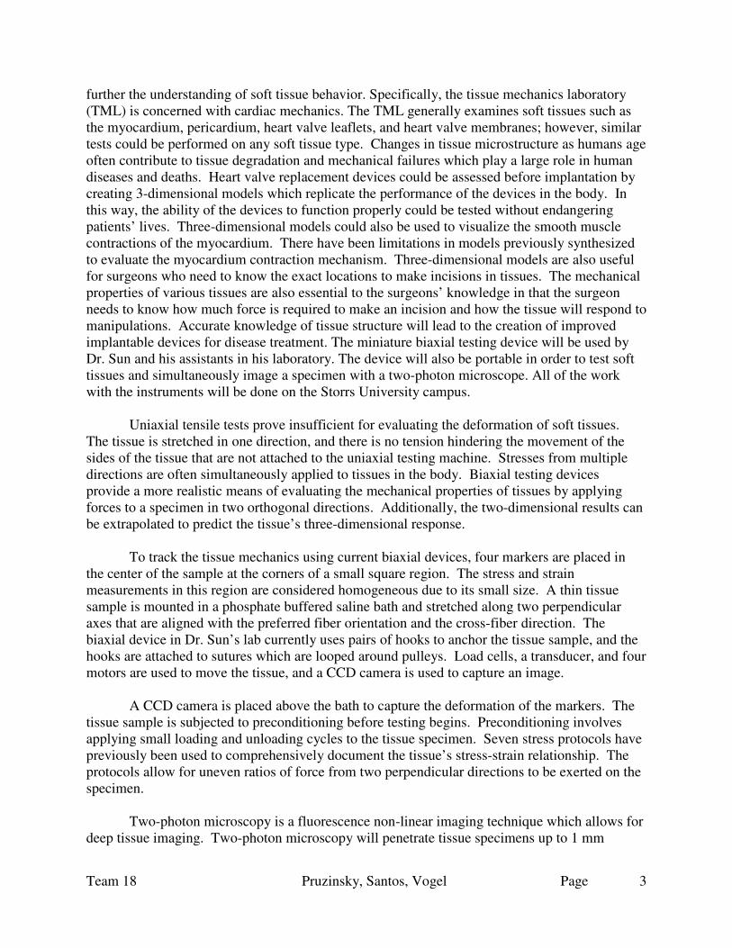
Figure 18. Multisim design of the circuit with resistors and terminal blocks.
The network of resistors involved a lot of connections between the motor drive, ground
and motors. Thus, many wires and alligator clips were used in the connections. The resistors were also inserted into a protoboard. In order to make the set-up neater, a PCB design was created and a PCB will be ordered from the company 4pcb. The Multisim file was transferred to Ultiboard, and from there Gerber files were made for the PCB.
The terminal blocks would be used to attach the voltage inputs from the motor drive to
the PCB. Two terminal blocks would be used to receive the output voltage as well and wires could be inserted into these blocks to transfer the output to the motors.
CCD Camera
One of the imaging modalities to be coupled with our instrument, is the CCD camera. A CCD camera is already in the Wei Sun lab. The CCD camera is a device commonly used in the medical field. An image sensor converts an electrical charge into a digitized signal which can be used as practical information. For our purpose, the sample will be marked with four graphite markers arranged approximately at the corners of an imaginary square in the center of the specimen. The CCD camera will record and track the movement of these markers. This displacement data is extremely important, as it provides us with information on how far the samples are being stretched in each direction.
Two-photon Microscopy

Team 18 Pruzinsky, Santos, Vogel Page
22
The driving reason for building a biaxial machine of small enough size so that it is transportable, is to be able to couple these tests with imaging via two-photon microscopy. The two-photon microscope is available in the biophysics building on the Storrs university campus. This technique allows us to visualize the tissue microstructure, namely collagen and elastin fibers. The samples may be viewed under the two-photon microscope after they have been biaxially tested.
Samples will need to be stained with fluorescent dye to be imaged. Stains can be chosen which have specific binding abilities to the desired microstructures. The microscope emits two-photons of light, as these come in contact with the dyes, and if there is enough energy. A fluorophore will be emitted from the dye. The intensity and wavelength of these fluorophores are transformed into an image. The entire biaxial testing device is placed underneath the two-photon microscope, which will be centered directly above the sample.
Underneath the two-photon microscope is a Thorlabs tabletop like the one located in the Tissue Mechanics lab. Additionally, there are only three inches between this tabletop and the lens of the microscope. There is also a small amount of space from the lens to a wall-like structure at the back of the device.
NI Stepper motor drives
Currently, Dr. Sun’s lab uses an NI stepper motor driver model number MID-7602 which can be used for our machine. This driver is necessary to control the motors and encoders. The specifications for this device are included in the references. Terminal blocks, which are green in color, are inserted into the driver. Different sized terminal blocks are used for the encoders and motors.
DIP switches on the front panel of the motor drive allow the user to adjust the current
supplied to the device. For the biaxial testing device, 1.4 A of current is supplied to each phase for the motors. This is the highest current setting on the motor drive. The motor drive also supplies 24V power for each phase of the motor drive. A picture of the top of the motor drive is shown below. The information on the top of the motor drive is useful for manipulating the current settings and connecting the motors to the driver. For instance, the wires of the motor were connected to the correct pins on the motor drive back panel that correspond to phase A, phase A knot, ground, phase B, and phase B knot. The places for the motors’ and encoders’ terminal blocks are also labeled on the back panel of the driver.

Team 18 Pruzinsky, Santos, Vogel Page
23
Figure 19. MID-7604/7602 motor drive.
NI LabVIEW
LabVIEW is the software program which will be used in conjunction with the Miniature Biaxial Testing Device (MBTD) for motion control. LabVIEW will be used for a control/user interface. Software to do this and control the driver is currently being worked on by Dave Kaputa. LabVIEW is ideal for this project because it can be employed in various aspects of the device. Firstly, LabVIEW controls the NI hardware. Second, LabVIEW has excellent data acquisition capability and can be used to store and collect data gathered during experiments. Finally, LabVIEW can also be used as a data analysis tool for the CCD and two-photon images. Translating these results from tests is an important component of this device. Without this capability, the machine would have no valuable contribution to the scientific and engineering world.
2.2 Prototype A photo of the prototype is shown in the figure below. The prototype looks similar to the
finalized SolidWorks assembly. Not shown in this figure are the computer, motor driver, and wires that are essential to make the device function.

Team 18
Figure 20. Prototype biaxial testing device. 2.2.1 Motor mounts
There are four right-angle top motor mounts which are 2 in. x 2 in. pieces of aluminum. These top mounts have one hole for the motor shaft and four small holes for securing the motor.There are eight right-angle, aluminum motor mount arms. They each have two holes for screwing into the side of the base. A photo of the motor mount pieces for a single motor is shown below.
Pruzinsky, Santos, Vogel
Figure 20. Prototype biaxial testing device.
angle top motor mounts which are 2 in. x 2 in. pieces of aluminum. These top mounts have one hole for the motor shaft and four small holes for securing the motor.
angle, aluminum motor mount arms. They each have two holes for screwing into the side of the base. A photo of the motor mount pieces for a single motor is shown
Page 24
angle top motor mounts which are 2 in. x 2 in. pieces of aluminum. These top mounts have one hole for the motor shaft and four small holes for securing the motor.
angle, aluminum motor mount arms. They each have two holes for screwing into the side of the base. A photo of the motor mount pieces for a single motor is shown
Team 18 Pruzinsky, Santos, Vogel Page
25
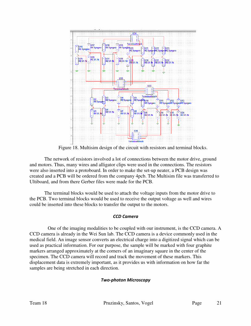
Figure 21. Front view of the motor mount arms and top mount on which the motor rests.
The motors in the device are attached to the mounts with small black screws. A small, black allen wrench is used to tighten the screws in the mounts and holes in the motors. The load cells, or dummy load cells, are attached to the linear actuator part of the hybrid motor. Nuts and bolts are used in this attachment. A wrench is used to tighten the nut at the end of the linear actuator.
Nuts and screws are used to secure the mounts to the base. Thirty-two #8-32 pan head
screws are used for the motor mounts. These screws are used to attach the arm mounts to the base, and to attach the arm mounts to the top mount. Additionally, sixteen #8-32 nuts are used for the motor mounts. Eight #4-40 nuts are used for the motor shafts and pulley mounts. The pulley mounts are attached to the load cells by #4-40 flathead screws. One screw is used for each pulley mount. One shoulder bolt is also used in each pulley assembly, so there are four of these in total.
2.2.2 LabVIEW
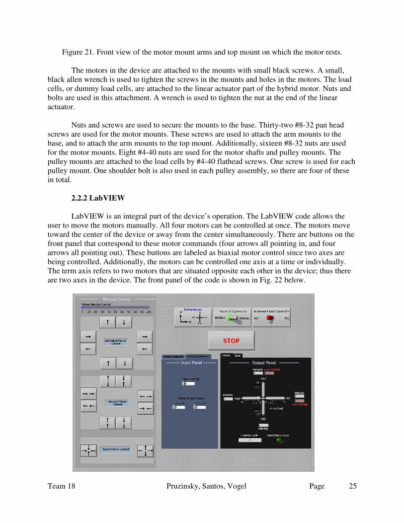
LabVIEW is an integral part of the device’s operation. The LabVIEW code allows the
user to move the motors manually. All four motors can be controlled at once. The motors move toward the center of the device or away from the center simultaneously. There are buttons on the front panel that correspond to these motor commands (four arrows all pointing in, and four arrows all pointing out). These buttons are labeled as biaxial motor control since two axes are being controlled. Additionally, the motors can be controlled one axis at a time or individually. The term axis refers to two motors that are situated opposite each other in the device; thus there are two axes in the device. The front panel of the code is shown in Fig. 22 below.

Team 18 Pruzinsky, Santos, Vogel Page
26
Figure 22. Front panel of labVIEW program. The user chooses the motor velocity by using the slider at the top of the front panel. The motor velocity is adjustable from 0 to 1000. Additionally there is a toggle button for the user to choose between testing and manual operation modes. When in testing mode, the motors all run at the same speed. Additionally, four motors will move toward the center of the device and then away from the center of the device. This cycle will occur multiple times and the current cycle that the program is on will be displayed on the front panel. The velocity of each motor will also be displayed on the front panel. The loads applied to the tissue sample will appear on the screen for each actual load cell as well. The motors that have dummy load cells attached to them will not have a load cell reading. Also, the LED button on the front panel’s output panel will light up when the tissue is being stretched.
2.2.3 Encoders and encoder wiring The encoders on the back of the motors are used to determine each motor’s absolute position. When the linear actuators are maximally extended (0.5 inch) they are at position zero. The motor’s position goes from 0 mm up to 12.7 mm as the linear actuator is pulled in toward the motor. It takes the motors about 10,400 steps to reach 0.5 inch. Limits are included in the LabVIEW code to prevent damage to the hardware. The limits were set at 100 and 10,000 steps. Once a motor reaches one of these limits, the warning sign shown in Fig. 23 appears on the front panel. The LED lights on the screen indicate which motor or motors are at the limit. Furthermore, the program switches over to the manual mode of operation so that the user can move the motor to within the range between the limits. The light blue LED light on the front panel indicates that mode of operation is changed to the manual control.
Figure 23. Error message that appears up every time the limits are reached.

Team 18 Pruzinsky, Santos, Vogel Page
27
The encoders’ wires are connected to 8-pin terminal blocks on the motor drive. The different colored wires are connected to specific pins on these terminal blocks. The table below describes what each encoder wire carries and the corresponding wire color.
Figure 24. Wiring description for encoder connectors.
The description of each pin of the encoder is matched with the description of the encoder
terminal block on the motor drive. This information is shown on the top panel of the motor drive and is shown in Fig. 25 below.
Figure 25. Pinout description for encoder terminal blocks.
Thus, the orange or red wire from pin 1 of the encoder is connected to pin 7 of the terminal block. The blue wire of the encoder is connected to pin 1 on the 8-pin terminal block. The brown or black wire of the encoder is connected to pin 8 of the encoder’s terminal block. Lastly, the yellow wire of the encoder is connected to pin 3 of the encoder’s terminal block.

Team 18
2.2.4 Tissue Specimen
A couple of different types of specimen were used to test the device. First a bovine pericardium square piece was cut and mounted in the pulley systems of the degraphite markers were placed on the tissue specimen with super glue and two size 22 fish hooks were inserted into each side of the tissue. Team 18 was able to view the tissue being stretched from its original dimensions. Another tissue speminiature biaxial device. A photo of the tissue sample in the device is shown in Fig
Figure 26. Tissue specimen mounted in device with saline bath underneath.
The threads should be approximately 25 mm frhooks. After the hooks and threads are secured in the tissue, the threads can be knotted a couple of times if they are too long to mount in the device. One or two tweezers are used to position each thread around a pulley. 2.2.5 Saline bath
The machined saline bath is shown in saline solution. Enough saline solution was placed in the bath to cover the tissue specimen and threads looped around the pulleys. The amoun
Pruzinsky, Santos, Vogel
A couple of different types of specimen were used to test the device. First a bovine pericardium square piece was cut and mounted in the pulley systems of the device. Four small graphite markers were placed on the tissue specimen with super glue and two size 22 fish hooks were inserted into each side of the tissue. Team 18 was able to view the tissue being stretched from its original dimensions. Another tissue specimen was also used for testing with the miniature biaxial device. A photo of the tissue sample in the device is shown in Fig
. Tissue specimen mounted in device with saline bath underneath.
The threads should be approximately 25 mm from one knot to the other knot on the
hooks. After the hooks and threads are secured in the tissue, the threads can be knotted a couple of times if they are too long to mount in the device. One or two tweezers are used to position
ned saline bath is shown in Fig. 27 below. The bath is filled with nine percent saline solution. Enough saline solution was placed in the bath to cover the tissue specimen and threads looped around the pulleys. The amount of solution added was between 250 and 300 mL.
Page 28
A couple of different types of specimen were used to test the device. First a bovine vice. Four small
graphite markers were placed on the tissue specimen with super glue and two size 22 fish hooks were inserted into each side of the tissue. Team 18 was able to view the tissue being stretched
cimen was also used for testing with the miniature biaxial device. A photo of the tissue sample in the device is shown in Fig. 26.
. Tissue specimen mounted in device with saline bath underneath.
om one knot to the other knot on the hooks. After the hooks and threads are secured in the tissue, the threads can be knotted a couple of times if they are too long to mount in the device. One or two tweezers are used to position
below. The bath is filled with nine percent saline solution. Enough saline solution was placed in the bath to cover the tissue specimen and
t of solution added was between 250 and 300 mL.

Team 18 Pruzinsky, Santos, Vogel Page
29
Figure 27. CNCed Plexiglas bath.
2.2.6 Load cells
DAQ Assistant is used to acquire data from the load cells. The load cells pick up voltage
readings which are converted into load cell values (g) based on a calibration curve. With the use of two load cells, one load cell could collect data from one axis while the other collects data from the other orthogonal axis. The load cells should have an excitation voltage of about 10V for the most amount of accuracy. The maximum voltage reading we obtained (at a 100g load) was about 5mV. The maximum excitation voltage for these load cells is 18V, at this voltage and at the maximum load (113g) we should obtain an 18mV signal with these ideal conditions. Since we are only using a 10V excitation, the maximum voltage (at 113 grams) should be 10mV. However, the maximum load was 100g so that maximum signal should be around 8.8mV. The error here could be due to hardware, electrical power dissipation, or just the load cell itself.
Figure 28. The load cell and pulley system mounted on the hybrid motor. 2.2.7 Motor Driver and motor wiring
The four wires of each motor were connected to terminal blocks. The motor’s four wires are colored red, red/white, green, and green/white. The red and red/white wires represent the
currents phase A and phase A, while the green and green/white wires represent phase B and
phase B respectively. The red wire is connected to pin 1 on a 5-pin terminal block. The red/white wire is connected to pin 2 on the terminal block. The green and green/white wires are connected

Team 18 Pruzinsky, Santos, Vogel Page
30
to pins 4 and 5 respectively on the terminal block. The third pin of the terminal block is for a ground connection. The 5-pin terminal blocks for the motors are inserted into the locations on the motor driver that are labeled ‘STEPPER MOTORS’. There are four locations for placing terminal blocks of this type. The label and some terminal blocks connected to the motor driver are seen in Fig. 30. The wiring diagram in the Fig. 29 below helps to accurately wire the motors to the motor drive. The diagram on the left in the figure is used for our motors since our motors are bipolar. It is shown that the red and red/white wires represent one phase while the green and green/white wires represent the other phase. HAYDON HYBRID LINEAR ACTUATORS: WIRING DIAGRAM
Figure 29. Wiring diagram for hybrid motors. The motors’ wires are not directly connected to the terminal blocks on the motor driver. Wires from the terminal blocks connect to the protoboard first. The output voltages from the circuits on the protoboard are connected to the motors’ wires with alligator test clips. Again, the circuit on the protoboard serves to reduce the voltage supplied to the motor to approximately 5 V.

Team 18 Pruzinsky, Santos, Vogel Page
31
Figure 30. Terminal block locations on motor drive.
A diagram of the Ultiboard circuit is shown in Fig. 31 below. This diagram contains 100 Ohm resistors, 1.1 kOhm resistors and terminal blocks. The Ultiboard diagram was exported into Gerber files to be able to order a PCB. The green lines in the figure below represent some of the traces or copper wires connecting different components of the circuit.
Figure 31. Ultiboard schematic of voltage divider circuit.

Team 18 Pruzinsky, Santos, Vogel Page
32
Terminal blocks were used in the design to organize the input voltages and the output voltages. The input voltages from the motor drive would be wired to two of the terminal blocks. The output voltages from the circuit are wired to the other two terminal blocks. The terminal blocks used in the circuit each have 8 pins available and are screw-type pins. A picture of a terminal block is shown in Fig. 32 below. These terminal blocks would be soldered onto the PCB.
Figure 32. Eight position terminal block sold by Digi-Key.
The team members determined a fan from a CPU would cool down the resistors the
motor driver is powered on. The CPU would also serve as a place to store the wires from the device and the board with the resistors.
2.2.8 Two-photon microscope set-up This information regarding the set-up and assembly of the device is important for the user
to know. When the device is brought to the two-photon microscope, it will need to be partially disassembled in order to fit under the microscope. The device fits underneath the microscope, but it is a little difficult to make it fit. A picture of a two-photon microscope is shown in the Fig. 33 below. Two of the motor mounts, as well as the load cells, pulley systems and motors, should be removed. Then the user should tilt the base to slide the device underneath the lens. The two motor mounts and motors can then be placed back on the device and screwed on.

Team 18 Pruzinsky, Santos, Vogel Page
33
Figure 33. Two-Channel Multiphoton System.
3. Realistic Constraints
Specimens to be tested using our miniature biaxial device will be on the range of 5 mm2 whose small size will present some different challenges. Currently, the biaxial devices in Dr. Wei Sun’s lab are much larger (table top size, about three square feet) and accommodate samples that are closer to 10mm2. Of concern is a mechanism to secure the sample. During testing it must be secured such that the sample is not damaged to the extent which may invalidate the test data. Secondly, a specimen requires enough strength so that there is no slippage of the tissue from the hooks, which would also cause inaccurate data. If slipping occurs the load created by the device will not transfer in entirety to the sample, also generating inaccuracy. Currently, for a larger sample sutures are hooked onto the sides, however this method will not work in a miniature design. In order to grip the specimen we propose a clamping mechanism to be attached to each side of a cross shaped tissue sample. To obtain accurate results, the tissue must not slip from the clamps or be damaged. This will require a clamp that is strong enough to secure it in place, but not too tight as well. Furthermore, a problem arises if the client would like to use this device on a range of specimen types. A mechanism which works for one tissue sample might not for another. In this report, we describe an optimal mechanism. However, this should be tested experimentally and different clamping mechanisms may be explored. Related to the small size required of the device makes building this machine difficult. First, scaling this machine down we will need to find components which are sufficiently small. Motors with both small dimensions and low power capabilities are necessary. This is because our sample does not require and cannot handle large loads. The required load to stretch our sample is as small as about two hundred grams. Parts will need to be machined for great precision as some of these components will be on the centimeter or millimeter scale. To provide good data from testing precision is a huge component. The machine currently in Dr. Sun’s lab is state-of-the art and produces very accurate data. There is a need for more testing and more machines with such

Team 18 Pruzinsky, Santos, Vogel Page
34
capabilities amongst the field of characterizing tissue properties. To meet engineering standards, and the same level of quality a lot of care is required during design, machining and assembly. This may require certain components of our device to be machined by a professional.
Another constraint is the transportability of the device and its set-up. First, the weight needs to be maintained at a level that is easy to carry. Set-up at the microscope may require additional time because the device and sample have to be transported to this site. For example, maintaining the specimen in a heated PBS or saline bath may be required to prevent tissue damage. The biaxial device is powered by motors, meaning that when transported a power supply must be available. This may require either battery power, or close proximity to an outlet
The device requires compatibility with the CCD camera and the two-photon
microscope. We have proposed a mirror to acquire this dual imaging however the set-up may be challenging. Adjustment and experimentation will need to be explored to determine the exact appropriate set-up. Additionally, in order to couple this device to two-photon microscopy an extra step to specimen preparation will be required. This may require fluorescent staining of the sample before testing and visualizing with the two-photon microscope. A method for tracking and measuring the tissue movement with the microscope will need to be addressed.
Lastly, because the device will be testing dissected tissue samples, proper health and
safety regulations must be met and taken into design consideration. The Wei Sun lab is capable of containing tissue samples with proper guidelines. For testing of our prototype device we will need to use our machine in the Sun lab. Furthermore, the two-photon microscopy lab will need to also have the proper tools to support these health concerns.
4. Safety Issues
Potential Electrical Safety Issues
There is a potential risk for electrical shock any time a current comes in contact with water. In this biaxial device, there will be several power and data cables running in near proximity of the saline solution. Precaution needs to be taken so that the wire connections, or any other electrically hazardous sites, do not touch the solution. This could be done by making a cover for the cables, or creating splash guards against outlets.
Potential Mechanical Safety Issues Care needs to be taken regarding the moving parts of the device, specifically with respect to the motors. These motors could potentially get overworked and overheated, creating a threatening environment for the device and users. The metal base conducts heat well, so it is possible that the temperature of the base will rise and potentially cause a minor burn on the handler if they touch the base. A precautionary measure for this could be to be diligent in monitoring the motor and stop tests before the motor heats up. Additionally, gloves can be worn by the handler during any and all transport.
Potential Biological Hazard Safety Issues

Team 18 Pruzinsky, Santos, Vogel Page
35
This device tests dissected tissue samples from humans, porcine, bovine, and other specimens. There is a high risk for handler infection and contamination from live tissue handling. To combat this, users of the device will be required to wear surgical masks and thick nylon examination gloves. Additionally, proper storage of the tissue samples as well as thorough cleaning of the entire device prior and post experimental use is also a strong preemptive measure for disease transmission. Chemical Hazards Small amounts of chemicals are added to water to prepare the saline bath. The user will wear gloves and a face mask to protect their skin from coming in contact with the chemicals and prevent inhalation of chemical vapors. Additionally, the tissue will be stored in a chemical solution. This solution may consist of DMSO, dimethyl sulfuric oxide, and RPMI, a redish solution. If this solution is used, the volume ratio of RPMI to DMSO is 4.5 : 0.5. Alternatively the tissue samples could be stored in a glutaraldehyde and saline solution.
Specimen Preparation Care should be taken when the user is using needles or hooks to attach sutures to the
specimen. The user should avoid pricking themself with the hooks especially as they are sharp and the specimen is small and hard to handle.
5. Impact of Engineering Solution
Cardiac disease is the number one killer of Americans to date. This being said, research and engineering solutions to lessen this number should be a high priority. In general, some heart disease treatments includes stents, which open occluded vessels helping to restore blood flow as well as prosthetic valves, which correct blood flow inside the heart. Our clients research includes evaluation of these candidate treatments to better understand their interaction with the body and to be able to begin to make improvements on design through this learning. Our device will be useful in this work and learning, which has a lot of potential for impact in the engineering world.
This device will provide a cost-efficient means of testing small tissue samples. No biaxial
testing device has been built before to test tissue samples with areas of five to ten square millimeters. Thus, this device will provide an accurate means of testing small tissues. Biaxial testing devices designed for larger specimens generally do not properly grip small tissue samples. Data obtained from these testing devices hence is inaccurate. Secure tissue grips meant for small tissue samples will contribute to the collection of valid data. The miniature biaxial testing machine will provide a way of quantifying the mechanical properties of small-sized heart tissues.
The miniature biaxial testing device would provide an effective way to test small tissue samples which is economically and environmentally friendly. Currently, small tissue samples are teared by biaxial testing devices meant for larger specimens. Having this device help to alleviate this problem. Additionally, the amount of tissue tested to get reliable data could be reduced by using the miniature biaxial testing device. Not as many preserved hearts would need to be purchased to generate data.

Team 18 Pruzinsky, Santos, Vogel Page
36
A database of the mechanical properties of the small tissues of the heart would allow the creation of constitutive models pertaining to these tissues. The models would aid surgeons to predict when a patient is in need of surgery more precisely than current methods allow. The models would also help simulate the behavior of the tissues in response to surgery. Heart valve replacement devices could be assessed before implantation by creating 3-dimensional computational models that replicate the performance of these devices in the body. In this way, the ability of the devices to function properly could be tested without endangering the patients’ lives. The mechanical properties would also help research groups to design prosthetics with properties which mimic those of the heart tissues. For example, the properties of heart valve leaflets would aid in the fabrication of new leaflet materials for heart valve prosthetics.
The two-photon microscope coupled with the miniature biaxial testing device would allow the user to view the microstructure as the tissue deforms. The visualization of the changes in the microstructure could help to determine the cause of tissue deformation or the mechanisms behind the microstructure changes. The explanation of why the tissue’s microstructure deteriorates would provide information for engineers to design tissue scaffolds which work to reduce the tissue deformation. The information on microstructural degradation could potentially contribute to new drug therapies which stop the mechanisms that cause the microstructure alterations.
6. Life Long Learning
There are many aspects of our project which contribute to further learning. The miniature biaxial testing device is intended for our clients work in cardiac mechanics, therefore it is important to understand this physiology background as well as the area of research the device will be used for. Dr. Sun’s lab used biaxial testing as a means to better understand cardiac tissue mechanic and material properties. From this knowledge, collected by biaxial testing, the lab can better evaluate emerging cardiac repair devices and techniques. This includes but is not limited to the tissue interactions with stents and bioprosthetic valves both experimentally and through finite element analysis in computational models.
The aorta has three layers called the intima, media and adventitia. The intima is the inner
layer which coincides with the interior of the artery. The media is the middle layer, and the adventitia is the outer layer. The aortic tissue is made up of different types of collagen. Type I collagen is the most abundant type present in arterial walls and in the body in general. A research team found that collagen types IV and VI were present in the intima and subintima layers by using gel electrophoresis [5]. This group also found that the proportions of collagen types III, V and I changed as the atherosclerosis conditions worsened.
The collagen fibers are arranged into fibrils and are concentrically oriented along the aorta. The collagen fibers likewise are arranged in a specific pattern in the valve leaflets. The collagen fibers form a sponge-like network in the leaflets [6]. The collagen fibers are structured as helical fibrils; however some strands stray in alternative directions and weave around the fibrils [6].

Team 18 Pruzinsky, Santos, Vogel Page
37
Ehlers-Danlos syndrome is a group of inherited connective tissue disorders in which the
body is incapable of producing sufficient amounts of collagen types I and III. There is no cure for this syndrome presently. Vascular Ehlers-Danlos syndrome affects blood vessels and organs. People with the vascular type of the syndrome have a higher risk than the average person for blood vessel rupture. However, the vascular type is rare and affects approximately 1 in 250,000 people. Two-photon microscopes have been used for cell imaging. Fluorescence signals within tissues are detected to produce the cell images. Green fluorescent proteins could be used to identify particular cells in tissues. Autofluorescence of collagen fibers could also be detected by two-photon laser scanning microscopy (TPLSM). A research group at the University of California, Irvine used this technique to determine collagen density and contraction in engineered human lung tissue [7]. Pulses of UV light were used to excite the autofluorescence of proteins in live tissues. The group then analyzed the raw data autofluorescence signal and converted this data into collagen concentration results.
7. Budget
7.1 Budget
An initial Budget of $1000 was provided to our team from the biomedical engineering department. Funding for other purchases were provided by Dr. Sun after our allotted budget was used. Further purchases included load cells, a heating mat, and extra encoder connectors.
Item Cost
Alligator Clips $6.32
Mansfield Supply Super Glue & sandpaper $6.67
Motors $1047
Plexiglas, McMaster $52.46
McMaster Carr screws & nuts $33.96
Machine shop materials and labor $145
Ponoma red & Black test clips $11.12

Team 18 Pruzinsky, Santos, Vogel Page
38
1.1kOhm and 100Ohm resistors, 5W $35.20
4-pin micro/ unterminated 4-wire discrete cable connector piece
$27.20
Total $1364.93
8. Team Members Contributions to Project
Team member: Leah Pruzinsky
It was necessary to break down the overall SolidWorks device design into individual
schematics that could be used as machining blueprints. I created the drawing for the base, as well as the connections between the threaded motor and the arm which linear motion was tranlsated to. In SolidWorks I also designed a clamping mechanism which could be machined by the team as an alternate idea to purchasing clamps.
I was in communication with Haydon Kerk, our supplier of the motors to be used in our
design. Joe Rossi, an HK engineer helped to describe the motors and ideas for incorporating them into our system. Namely, making us aware of the threaded shaft and holes in the back so a right hand bracket could attach the motors to our base. Additionally, it was important to determine the compatibility of these motors with the existing equipment that our client has. Both Joe Rossi and Dave Kaputa were a big help for this. I met with Dave to understand the compatibility between the driver in the lab and the motors we wanted to purchase. I also spoke to Peter Glaude in the Universities machine shop to discuss some component of our design.
I have been continually working on updating the team website, keeping track of our
budget and materials, helping to submit purchase orders and also responsible for the team’s Microsoft Project Gantt chart. Team member: Stephany Santos
My contributions mainly revolved around the creation of SolidWorks figures for our design. The design I created in the preliminary alternative design period was selected as our optimal design, so a lot of work has been put in to update the SolidWorks files to be as accurate as possible and fit our changing design needs.
The first semester I chose several of the specifications of the device such as material and
provider, and spoke to a few companies on getting quotes for possible materials. Such materials include the camera stand base and the mirror clip and base. I have worked with Caitlin Martin to attain a sample of bovine pericardium and have nominally trained my team members in specimen

Team 18 Pruzinsky, Santos, Vogel Page
39
preparation and on how the biaxial machine currently found in Dr. Sun’s lab works. I have also worked on report formatting and overall editing as a part of a collaborative effort with my teammates. I have contributed a few items to the Microsoft Project Gantt Chart, as well as the budget.
The second semester, I put a lot of time and effort into designing and creating parts at the
machine shop. I made the pulleys by myself, and worked alongside Leah to create the base and the motor mounts. I also spent several hours checking the accuracy of our design and ensuring it was perfectly straight, level, and in the desired planes of motion.
I also spent a great deal of time with LabVIEW programming. It was a team effort at
large, but individually I created the code for the encoders and limit switches, and worked to make the front panel as aesthetically pleasing and user friendly as possible. Administratively, I created videos for our client so he could see the progress without going to the lab, and created the majority of the user manual.
Team member: Christine Vogel
The first semester was spent mainly on research and making SolidWorks designs to visualize designs. I looked into several options for tissue specimen attachments such as alligator clips and microvascular clamps, but in the end the team returned to using small hooks as are used in the original biaxial testing machine in the TML. I also researched a load cell from the company Transducer Techniques, but the team decided on using a bending beam load cell. I spent some time learning about the mechanical dimensions of the two photon microscope and Thorlabs tabletop beneath this microscope as well.
During the spring semester I worked on a collection of tasks. I worked on the voltage divider circuit and wiring the motors and encoders to the motor driver. Additionally, I learned about designing a circuit in Multisim, and exporting this file to the software Ultiboard and into Gerber files for PCB synthesis. These tasks involved understanding technical drawings and learning a lot of new information for the NI software programs. Additionally, this semester I worked on the procedure for preparing tissue specimens. I prepared a few tissue specimens over the course of the semester. The preparation involved carefully inserting the barbed hooks into the tissue specimen. Patience was needed for tying knots through the holes in the small hooks. I learned about the LabVIEW program that runs the device and communicates with the DAQ hardware and camera this semester as well.

Team 18 Pruzinsky, Santos, Vogel Page
40
9. Conclusions
The miniature biaxial testing device will be a novel addition to the engineering community. Biaxial testing devices currently sold cannot test tissue specimens below ten square millimeters. Thus, the device we propose to build will stretch a tiny tissue specimen in two perpendicular directions, release the force applied so that the tissue relaxes, and repeat this process many times. Our design features four hybrid motors/linear actuators, encoders, two load cells, two dummy load cells, pulleys, an aluminum base and a cross-shaped saline bath. A heating mat is also available for maintaining the temperature of the saline bath close to body
temperature (37°C) while biaxial testing is being performed. The load cells are capable of measuring small loads as low as 0.25 pounds. The pulleys serve to position threads attached to the tissue specimen. The entire device is housed in an aluminum base which allows it to be portable to a two-photon microscope in the Pharmacy building on campus. The user should be able to partially disassemble the device to place it under the microscope lens, and then assemble the parts of the device that were taken apart. The two-photon microscope allows the user to visualize microstructure changes as a tissue specimen is tested. Of particular interest are the collagen and elastin fibers in the tissue as it is being stretched. As the two-photon microscope operates in the dark, only one imaging modality, the CCD camera or the two-photon microscope, can be used at a time. The CCD camera will track the positions of the markers on the tissue specimen as it is biaxially tested. This camera will be connected to the computer and a LabVIEW program will aid in the recording of a video of the tissue deformation while the sample is tested. All in all, the small biaxial testing machine is operated with the use of LabVIEW-programmed encoders controlling the motors. DAQ Assistant is used to record data from load cells as the tissue is tested. The data obtained from the load cells is important for revealing tissue properties, which can contribute to creating accurate simulations and building appropriate bioprosthetic cardiovascular devices.

Team 18 Pruzinsky, Santos, Vogel Page
41
10. References
[1] Sacks, Michael S. and Wei Sun. 2003. "Multiaxial Mechanical Behavior of Biological
Materials." The Annual Review of Biomedical Engineering 5 (1): 251.
[2] H. Hung, C. Chuong, A. Steinhart, J. Trexler, K. Billiar, “Design of a Biaxial Test Device For
Compliant Tissue,” Departments of Biomedical and Mechanical Engineering, Worchester
Polytechnic Institute, 100 Institute Road, Worchester, MA 01609.
[3] Brodland and Wayne, G. (2007). U.S. Patent No. 7,762,146. Washington, DC: U.S. Patent and
Trademark Office.
[4] Ghosh and Tushar, K. (1999). U.S. Patent No. 6,487,902. Washington, DC: U.S. Patent and
Trademark Office.
[5] K. Murata, T. Motayama, and C. Kotake, “Collagen types in various layers of the human
aorta and their changes with the atherosclerotic process,” Atherosclerosis [online], vol. 60 (no.
3), pp. 251-262, (Jun. 1986). Available http://www.ncbi.nlm.nih.gov/pubmed/3089234.
[6] M. Misfeld and H. Sievers, “Heart valve macro- and microstructure,” Philosophical
Transactions of the Royal Society Biological Sciences [online], vol. 362, pp. 1421-1436, (2007).
Available http://rstb.royalsocietypublishing.org/content/362/1484/1421.full.pdf.
[7] A. Agarwal, M. L. Coleno, V.P. Wallace, W. Wu, C. Sun, B. J. Tromberg, and S. C.
George, “Two-Photon Laser Scanning Microscopy of Epithelial Cell-Modulated Collagen
Density in Engineered Human Lung Tissue,” Tissue Engineering [online], vol. 7 (no. 2),
pp. 191-203, (2001). Available http://georgelab.eng.uci.edu/pdfs%20of%20papers/Two-
photon%20laser%20scanning%20microscopy.pdf.

Team 18 Pruzinsky, Santos, Vogel Page
42
11. Acknowledgements
TML Members :
• Dr. Wei Sun
• Dave Kaputa
• Shamik Bhattacharya
• Thuy Pham
• Caitlin Martin
• Kewei Li UConn Affiliates:
• Dr. J. Enderle
• Sarah Brittain
• Peter Glaude
• Serge Doyon
• Jennifer Desroisres
• Fred Wright Other Corporate and University Partners:
• Joe Rossi
• Dr. J. Loturco
• Dr. K. Billiar
12. Appendix
12.1 Updated Specifications
Physical
Component Material
Saline bath container Polymethyl methacrylate (Plexiglas)
Dummy load cell 304 Stainless steel
Pulleys Dacron
Motor Mount Arms (8) Right angle aluminum
Motor mounts , top (4) Right angle aluminum 2x2in

Team 18
Pruzinsky, Santos, Vogel Page 43
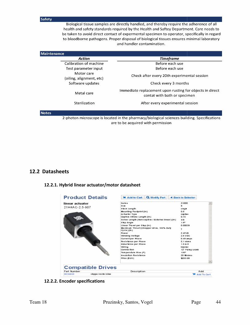
Team 18
12.2 Datasheets
12.2.1. Hybrid linear actuator/motor datasheet
12.2.2. Encoder specifications
Pruzinsky, Santos, Vogel
linear actuator/motor datasheet
12.2.2. Encoder specifications
Page 44

Team 18 Pruzinsky, Santos, Vogel Page
45

Team 18 Pruzinsky, Santos, Vogel Page
46
12.2.3. Load cell spec sheet

Team 18 Pruzinsky, Santos, Vogel Page
47