final synthesis report - transportation research...
TRANSCRIPT

NAS 149/09, NCHRP 20-07/348 Review of the AASHTO LRFD Movable Highway Bridge Design Specifications for Future Updates
Final Synthesis Report
Parsons Brinckerhoff Synthesis Report Page 1 of 57
Final Synthesis Report
Prepared for:
National Academy of Sciences
National Cooperative Highway Research Program
Prepared by:
Parsons Brinckerhoff, Inc.
One Penn Plaza, NY, NY 10119
In Association with: James A. Swanson, Ph.D.
May 22, 2015
The information contained in this report was prepared as part of NAS Project 149/09 and
NCHRP Project 20-07, Task 348, for the National Academy of Sciences (NAS) and National
Cooperative Highway Research Program (NCHRP), respectively.
SPECIAL NOTE: This report IS NOT an official publication of the National Cooperative
Highway Research Program, Transportation Research Board, National Research Council, or The
National Academies.

NAS 149/09, NCHRP 20-07/348 Review of the AASHTO LRFD Movable Highway Bridge Design Specifications for Future Updates
Final Synthesis Report
Parsons Brinckerhoff Synthesis Report Page 2 of 57
Acknowledgements
This study was conducted for the T-8 Movable Bridges technical committee of the Highway
Subcommittee on Bridges and Structures of the American Association of State Highway
Transportation Officials (AASHTO), with funding provided through the National Cooperative
Highway Research Program (NCHRP) Project 20-07, Task 348 Review of the AASHTO LRFD
Movable Bridge Design Specifications for Future Updates. The NCHRP is supported by annual
voluntary contributions from the state Departments of Transportation. The report was prepared
by Parsons Brinckerhoff, Inc. Michael J. Abrahams P.E. was the Principal Investigator and Scott
Snelling P.E. was the Deputy Principal Investigator. The work was guided by a technical
working group. The project was managed by Waseem Dekelbab, Ph.D., P.E., PMP, NCHRP
Senior Program Officer.
Disclaimer
The opinions and conclusions expressed or implied are those of the research agency that
performed the research and are not necessarily those of the Transportation Research Board or its
sponsoring agencies. This report has not been reviewed or accepted by the Transportation
Research Board Executive Committee or the Governing Board of the National Research Council.

NAS 149/09, NCHRP 20-07/348 Review of the AASHTO LRFD Movable Highway Bridge Design Specifications for Future Updates
Final Synthesis Report
Parsons Brinckerhoff Synthesis Report Page 3 of 57
Table of Contents EXECUTIVE SUMMARY ......................................................................................................................................................................... 4
TASK 1 – ANNOTATED LITERATURE REVIEW .............................................................................................................................. 5
TASK 2 – SYNTHESIZE THE VARIOUS TYPES OF 1) MECHANICAL SYSTEMS AND 2) ELECTRICAL DRIVES AND CONTROLS .............................................................................................................................................................................................. 18
TASK 3 – DISCUSS THE APPLICATION OF RELIABILITY-BASED DESIGN TO MECHANICAL, ELECTRICAL, AND TRAFFIC/MARINE SAFETY SYSTEMS FOR MOVABLE BRIDGES .......................................................................................... 30
TASKS 4 & 5 – OUTLINE OF PROPOSED AREAS OF AASHTO LRFD MOVABLE BRIDGE DESIGN SPECIFICATIONS FOR FUTURE UPDATES ................................................................................................................................... 42
TASK 6 – PRESENT TO THE AASHTO HSCOBS TECHNICAL COMMITTEE T-8 MOVABLE BRIDGES ....................... 52
TASK 7 – DEVELOP RESEARCH PROBLEM STATEMENT ....................................................................................................... 53
TASK 8 – SYNTHESIS REPORT ......................................................................................................................................................... 55
PROJECT SCHEDULE: ......................................................................................................................................................................... 56
MEETINGS, DELIVERABLES, AND SCHEDULE MILESTONES: ................................................................................................ 57

NAS 149/09, NCHRP 20-07/348 Review of the AASHTO LRFD Movable Highway Bridge Design Specifications for Future Updates
Final Synthesis Report
Parsons Brinckerhoff Synthesis Report Page 4 of 57
EXECUTIVE SUMMARY
The current primary design guide for movable bridge design and construction is the AASHTO LRFD Movable Highway Bridge Design Specifications (Specifications), 2nd Edition, 2007, with 2008, 2010, 2011, and 2014 Interim Revisions. Based on the input from movable bridge owners, designers, and industry representatives, the current specifications need updating to incorporate the LRFD method, based on reliability-based design methodology and to reflect advances in mechanical systems, electrical drives and controls, and traffic/marine safety systems. The objectives of this research are to:
(1) Develop a stand-alone synthesis of the various types of mechanical systems and electrical controls and drives currently being used in movable bridges.
(2) Identify the areas of the AASHTO LRFD Movable Bridge Design Specifications that require modification, addition, or deletion to incorporate the LRFD method to reflect advances in structural materials and design, mechanical systems, electrical drives and controls, and traffic/marine safety systems.
(3) Propose recommendations for future research needs. This Draft Synthesis Report encompasses the deliverable for the following tasks: Task 1: Review relevant literature and practices Task 2: Synthesize the various types of 1) Mechanical systems and 2) Electrical drives and controls Task 3: Discuss the application of reliability-based design to mechanical, electrical, and traffic/marine safety systems for movable bridges Task 4: Outline of proposed areas of AASHTO LRFD Movable Bridge Design Specifications for future modification, addition, and deletion Task 5: Revise the outline per NCHRP project panel comments Task 6: Present to the AASHTO HSCOBS Technical Committee T-8 Movable Bridges; Revise outline Task 7: Develop research problem statement Task 8: Synthesis Report – including draft, incorporation of comments, and final report
NAS 149/09, NCHRP 20-07/348 Review of the AASHTO LRFD Movable Highway Bridge Design Specifications for Future Updates
Final Synthesis Report
Parsons Brinckerhoff Synthesis Report Page 5 of 57
TASK 1 – ANNOTATED LITERATURE REVIEW
The Task 1 reviewed literature is listed and annotated below. In general, the literature is ordered according
to its relevance.
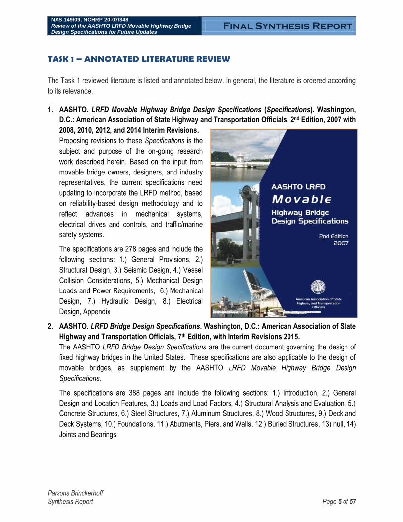
1. AASHTO. LRFD Movable Highway Bridge Design Specifications (Specifications). Washington,
D.C.: American Association of State Highway and Transportation Officials, 2nd Edition, 2007 with
2008, 2010, 2012, and 2014 Interim Revisions.
Proposing revisions to these Specifications is the
subject and purpose of the on-going research
work described herein. Based on the input from
movable bridge owners, designers, and industry
representatives, the current specifications need
updating to incorporate the LRFD method, based
on reliability-based design methodology and to
reflect advances in mechanical systems,
electrical drives and controls, and traffic/marine
safety systems.
The specifications are 278 pages and include the
following sections: 1.) General Provisions, 2.)
Structural Design, 3.) Seismic Design, 4.) Vessel
Collision Considerations, 5.) Mechanical Design
Loads and Power Requirements, 6.) Mechanical
Design, 7.) Hydraulic Design, 8.) Electrical
Design, Appendix
2. AASHTO. LRFD Bridge Design Specifications. Washington, D.C.: American Association of State
Highway and Transportation Officials, 7th Edition, with Interim Revisions 2015.
The AASHTO LRFD Bridge Design Specifications are the current document governing the design of
fixed highway bridges in the United States. These specifications are also applicable to the design of
movable bridges, as supplement by the AASHTO LRFD Movable Highway Bridge Design
Specifications.
The specifications are 388 pages and include the following sections: 1.) Introduction, 2.) General
Design and Location Features, 3.) Loads and Load Factors, 4.) Structural Analysis and Evaluation, 5.)
Concrete Structures, 6.) Steel Structures, 7.) Aluminum Structures, 8.) Wood Structures, 9.) Deck and
Deck Systems, 10.) Foundations, 11.) Abutments, Piers, and Walls, 12.) Buried Structures, 13) null, 14)
Joints and Bearings

NAS 149/09, NCHRP 20-07/348 Review of the AASHTO LRFD Movable Highway Bridge Design Specifications for Future Updates
Final Synthesis Report
Parsons Brinckerhoff Synthesis Report Page 6 of 57
3. AASHTO. Guide Specifications and Commentary for Vessel Collision Design of Highway
Bridges, 2nd Edition, with 2010 Interim Revisions. Washington, D.C.: American Association of
State Highway and Transportation Officials, 2009.
“The intent of the AASHTO provisions is to provide bridge components with a „reasonable‟ resistance
capacity against ship and barge collisions. In navigable waterway areas where collision by merchant
vessels may be anticipated, the Guide Specification requires that bridge structures be designed to
prevent collapse of the superstructure by considering the size and type of vessel fleet navigating the
channel, available water depth, vessel speed, structure response, the risk of collision, and the
operational classification of the bridge.” These guide specifications include section 7.4 Movable Bridge
Protection. “Movable bridges are particularly susceptible to interrupted service as a result of vessel
collision because even a minor impact on the substructure or superstructure can cause mechanical
equipment to jam or fail.” “As a result of their relatively narrow horizontal spans, and the increase in
size and frequency of vessels in most waterways today, many movable bridges have a relatively high
risk of vessel collision.”
4. AASHTO. Guide Specifications for Bridges Vulnerable to Coastal Storms. Washington, D.C.:
American Association of State Highway and Transportation Officials, 2008.
“These Specifications give Owners the opportunity to apply coastal loads in either the strength limit
state or the extreme limit state, depending on the Owner‟s assessment of the criticality of the bridge.
Evacuation and rescue/recovery of the affected area should be a prime factor when considering a
system of bridges serving a coastal area.” Coastal loads include storm surge and wave loading. “No
effect of anticipated climate change has been accounted for herein. Individual Owners may include this
feature depending on their jurisdiction‟s policy in this regard.” “Wherever practical, the vertical
clearance of highway bridges should be sufficient to provide at least 1 foot of clearance over the 100-
year design wave crest elevation, which includes the design storm water elevation.” Design strategies
are presented for mitigating or accommodating coastal forces. Movable bridges are not explicitly
addressed in these Specifications. However, many movable bridges are located in coastal areas and
subjected to the coastal loads addressed in these Specifications.
5. AASHTO. Movable Bridge Inspection, Evaluation, and Maintenance Manual (AASHTO 1998).
Washington, D.C.: American Association of State Highway and Transportation Officials, 1998.
Updating this AASHTO 1998 manual is the subject and purpose of the on-going research currently
being performed by Parsons Brinckerhoff under the separate project NCHRP 14-32. The manual no
longer reflects the latest research and developments in movable bridge design and evaluation, and so
does not provide current guidance for the inspection, evaluation, and maintenance of the nation‟s
inventory of highway movable bridges. In particular, the manual does not incorporate Load Resistance
Factor Design (LRFD) reliability-based methods, nor does it incorporate element-level condition
assessment methods. In addition, the manual does not provide clear guidance regarding
recommended scope and frequency of routine and in-depth mechanical and electrical inspections. The
AASHTO 1998 manual does provide guidance regarding safety inspections of movable bridges, as well
as evaluation methods based on Working Stress Design (WSD).

NAS 149/09, NCHRP 20-07/348 Review of the AASHTO LRFD Movable Highway Bridge Design Specifications for Future Updates
Final Synthesis Report
Parsons Brinckerhoff Synthesis Report Page 7 of 57
The manual is 606 pages and includes the following parts: 1.) General, 2.) Inspection, 3.) Evaluation,
4.) Maintenance, Appendices, Glossary, and Index. Condition inspection of hydraulic equipment for
movable bridges is covered.
Upon the completion of NCHRP Project 14-32 in 2016, it is anticipated that significant revisions to the
manual will be implemented. In particular, element definitions for mechanical and electrical systems of
movable bridges have been proposed.
6. NEN 6786/A1. Requirements for the Design of Movable Bridges. Netherlands, 2002
This 300 page standard was written in the Dutch language. To facilitate review, it was machine
translated to English. The standard states “This standard provides technical provisions for the design of
mechanical equipment; electrical installation of all types of movable bridges for road and rail traffic.”
“The semi-probabilistic calculation method is introduced in NEN 6786.”
“Through application of the standard, the minimum reliability index (f3) is:
- Ultimate Limit State, when Wind Load controls: f3 = 2.6
- Ultimate Limit State, if other loads control: f3 = 3.6
- Serviceability Limit State: f3 = 0.5
“Movable bridges can be distinguished into six logical types according to the nature of their movement:
- Rotation about a horizontal axis: bascule bridges, bang bridges, draw bridges, Strauss
bridges, certain construction equipment for ferries
- Rotation about vertical axis: turn bridges, crane bridges
- Horizontal translation: travelling, ship or float bridges
- Vertical translation: vertical lift bridge
- Rotation about a horizontal axis, together with a horizontal translation: rolling-bascule
bridge
- Rotation about a horizontal axis, together with a vertical translation: certain
construction equipment for ferries”
A substantially updated version of this standard is expected to be published for comment, but not
implemented, in September 2014. The committee contact is Rolph Holthuijsen.
7. NEN 6787. Design of Movable Bridges – Safety. Netherlands, 2003
This 60 page standard was written in the Dutch language. To facilitate review, it was machine
translated to English. The standard addresses the dangers characteristic of movable bridges in the
context of European legislation of the Machinery Directive, and “CE” declaration. The standard states
“A risk assessment shall be performed to identify potential safety hazards and determine whether risk
can and must be reduced. Risks shall be reduced according to following sequence: 1.) change the
design to eliminate the risk, 2.) apply physical protections such as guards, 3.) inform the user about the
danger by signals (light and sound) and indications (signs), 4.) inform the user of the danger in a user
manual. The later mitigation strategies shall only be used when the earlier strategies are not feasible.”

NAS 149/09, NCHRP 20-07/348 Review of the AASHTO LRFD Movable Highway Bridge Design Specifications for Future Updates
Final Synthesis Report
Parsons Brinckerhoff Synthesis Report Page 8 of 57
8. DIN 19704. Hydraulic Steel Structures. German Standard, Draft 2012
This standard was written in the German language. To facilitate review, it was machine translated to
English. The standard states “The standard is applicable to the calculation and design of steel hydraulic
structures [such as locks and dams], including mechanical and electrical equipment.” “The standard
also applies to…canal [movable] bridges.” A search revealed zero hits for the words “reliability” or
“probability”. However, the standard includes the following limit states that apply to mechanical and
structural calculations: ultimate limit state and serviceability limit state. There is also a proof of fatigue
requirement such that “machine parts and their electrical equipment, except wearing parts (ropes, etc)
shall have a useful life of 35 years.”
9. CAN/CSA-S6-06. Canadian Highway Bridge Design Code, including Supplement Nos. 1, 2 and 3.
Toronto, Ontario, Canada: Canadian Standards Association, 2013
Section 13 Movable Bridges “specifies the requirements for the design, inspection, maintenance,
construction, and rehabilitation of conventional movable highway bridges, i.e. bascule (including rolling
lift), swing, and vertical lift bridges, and deals primarily with the components involved in the operation of
such bridges.” Of the 1078-page-long code, the 68 pages in Section 13 address movable bridges.
Canada, particularly Ontario, was a leader with regards to implementing reliability-based design
standards for structures. However, the Canadian standard does not use reliability-based methods for
mechanical and structural design for movable bridges.
10. Eurocode 3, Part 2-1 BS EN 1993-2, Design of Steel Bridges, 2008
This code specifies rules for the structural design of steel bridges and steel elements of composite
bridges and bridges mainly of other construction materials. There is no explicit discussion of movable
bridges, but the code may be applied to the design of movable bridge structures. The new structural
Eurocodes offer increased economy in design over most existing codes of practice.
11. AREMA. Manual for Railway Engineering. Chapter 15, Part 6, 2008
This standard applies to the design of movable railroad bridges and uses working stress design, not
probability-based, for structures and machinery.
12. Chicago DOT. Design Standards for Chicago Bascule Bridges. Chicago, IL. City of Chicago,
Department of Transportation, April 1994
This 13 page design standards consists of three parts: structural design, electrical system, and
machinery design. The design is in accordance with AASHTO Standards Specifications and AASHTO
Standards Specifications for Movable Bridges with modifications.
13. AASHTO. Standard Specifications for Movable Highway Bridges, Washington, D.C.: American
Association of State Highway and Transportation Officials, 1988
This superseded standard applies to the design of movable highway bridges and uses working stress
design, not probability-based, for structures and machinery.

NAS 149/09, NCHRP 20-07/348 Review of the AASHTO LRFD Movable Highway Bridge Design Specifications for Future Updates
Final Synthesis Report
Parsons Brinckerhoff Synthesis Report Page 9 of 57
14. AASHTO. Research by the T-8 Movable Bridge Technical Committee. American Association of
State Highway and Transportation Officials
The movable bridge committee has sponsored and published movable bridge related research,
including: Span Lock Design Study – AASHTO AS 13-0024; Survey on Barriers for Movable Bridges;
Research into Various Deck Options Including FRP, Grid, and Composite Deck Systems; Structural
Health Monitoring.
15. HMS. Archive of Technical Papers, Heavy Movables Structures, 1985 through 2012
The Heavy Movable Structures (HMS) organization has hosted symposia biennially since 1985,
including the publication and presentation of technical papers. These papers are available for
download from the organization on-line archive. The papers address a wide range of technical topics,
including many suggestions for improving the design methods for movable bridges, including:
- Alison, Cragg. Rational Specifications for Speed Reducers on Movable Bridges. 2008
- Cragg. Observations and Comments: AASHTO Design Practices for Movable Bridge
Operating Machinery. 1990
- Bluni. Comparison of Movable Bridge Design in Domestic and Foreign Markets. 2008
- Hanley. Hydraulic Systems for Movable Bridges. 1985
- Soot. The Need for Single Failure Proof Design for the Movable Structures. 1990
- Schultz. Self Destruction of a Strauss Bascule. 1990
- Al-Smadi, Protin. Thinking Outside the Box – Using Small Diameter Sheaves. 2006
- Abrahams. Seismic Performance of Movable Bridges, 1998
16. Kulicki, Bridge Engineering Handbook, Second Edition, Fundamentals, Highway Bridge Design
Specifications, Second Edition. CRC Press, 2014
The book includes an 18 page long chapter that discusses the theoretical basis for establishing safety
in the AASHTO Bridge Design Specifications using a reliability-based, probability-based approach.
The chapter discusses how a reliability-index (β) of 3.5, corresponding to a probability of structural
member failure of 2 in 10,000, with this calibration informed by study of the previously existing
allowable stress design approach. The reliability-index is then used by the code writing body to select
load factors and calculate corresponding resistance factors.
Note that the probability-based methods used to establish the LRFD Highway Bridge Design
Specifications relied upon a representative sample of fixed bridges, from various regions of the USA.
17. Kulicki, Evolution of the AASHTO Bridge Design Specifications – Part 1 & Bridge Failure and
Design Specifications – Part 2, State University of New York at Buffalo, 2010
Presentation with slideshow summarizing the development process for the LRFD Highway Bridge
Design Specifications. Part 2 uses case studies of historical bridge collapses in the USA and the
associated responses with regards to revising bridge design specifications.
18. Tobias, Perspectives on AASHTO Load and Resistance Factor Design, 2011
The article states “The initial publication of the LRFD Code was prototypical in nature. It succeeded in
establishing a framework for introducing the bridge community to the notion of a complete structural

NAS 149/09, NCHRP 20-07/348 Review of the AASHTO LRFD Movable Highway Bridge Design Specifications for Future Updates
Final Synthesis Report
Parsons Brinckerhoff Synthesis Report Page 10 of 57
design specification on the basis of reliability theory and simultaneously incorporated a significant
amount of recent engineering developments in a wide range of areas.” “With each successive year
since its initial publication, the LRFD Code has been refined, revised, and improved.” “The AASHTO-
LRFD Code was first published in 1994 after 6 [six] years of development. The FHWA established
October 1, 2007 as the date for that all new bridges in the United States should be designed according
to the LRFD Code.” “The forces that drive the continual evolution of the LRFD Code and other
structural AASHTO publications are still vibrant within the bridge engineering community.”
19. FHWA HI-95-017. NHI Course No. 13061 - Load and Resistance Factor Design for Highway
Bridges – Participant Notebook. Washington D.C.: U.S. Department of Transportation, 1995
This two volume reference provides an overview and commentary regarding the development and
implementation of the AASHTO LRFD Bridge Design Specifications.
20. Abrahams, Seismic Performance of Movable Bridges, HMS 7th Biennial Symposium, November
1998. This article points out that the AASHTO bridge design specifications do not address the seismic
design of movable bridges and that the AASHTO movable bridge design specifications have a limited
consideration for the seismic design regarding a movable bridge in the open vs. closed position and
that the current approach may significantly under or over-estimate the risk The article proposes a
method to provide a uniform hazard for the seismic design of movable bridges depending upon the
durations in the open and closed positions. By extension this same approach could be applied to other
load cases such a wind and ship collision.
21. Abrahams, Snelling, VanDeRee, Bridge Engineering Handbook, Second Edition, Superstructure
Design, Chapter 9 Movable Bridges. CRC Press, 2014
This chapter provides a broad overview of the types of movable bridges in the United States, including
typical mechanical and electrical equipment. The 34-page-long chapter also addresses typical design,
maintenance, and inspection issues related to movable bridges. The second edition is an update of
Chapter 21, Movable Bridges, Bridge Engineering Handbook, 2000 that was authored by Michael J.
Abrahams.
22. Birnstiel, ICE Manual of Bridge Engineering, Chapter Movable Bridges, London, England:
Institution of Civil Engineers, 2008.
This chapter provides “an elementary introduction to movable bridge engineering. Movable bridges are
classified and various types are described and illustrated with examples built in the United Kingdom,
Europe, and America. Span drive and stabilizing machinery is treated and the interdependency
between the superstructure, mechanical and hydraulic machinery, and electrical controls is
emphasized. A movable bridge is a machine and, as such, dynamic effects [are] considered. Major
design issues, including safety and redundancy, are discussed as well as design specifications and
future trends in the architecture and engineering of movable bridges.”
“The motions of all movable bridges are a combination of rotation and translation; the differences between types are due to the axes selected for these displacements. In terms of primary displacement and axes of displacement, movable spans are usually categorized as follows:

NAS 149/09, NCHRP 20-07/348 Review of the AASHTO LRFD Movable Highway Bridge Design Specifications for Future Updates
Final Synthesis Report
Parsons Brinckerhoff Synthesis Report Page 11 of 57
- Rotation about a fixed transverse horizontal axis (trunnion bascule)
- Rotation about a transverse horizontal axis that simultaneously translates
longitudinally (rolling bascule)
- Rotation about a fixed vertical axis (swing)
- Translation along a fixed vertical axis (vertical lift)
- Translation along a fixed horizontal axis (retractile and transporter)
- Rotation about a fixed longitudinal axis (gyratory)
- Rotation about multiple transverse horizontal axes (folding)”
23. Koglin. Movable Bridge Engineering, New York: John Wiley & Sons, 2003
This reference book provides an overview of the design, inspection and maintenance of movable
bridges in the United States.
24. Hool & Kinne. Movable and Long Span Steel Bridges, New York: McGraw-Hill Book Company,
1923
This historic reference book provides an overview of the design of movable bridges.
25. Hovey, Movable Bridges, Volumes I and II, New York: John Wiley & Sons, 1927
This historic reference book provides an overview of the design of movable bridges and preceded the
first AASHTO Movable Bridge Specifications.
26. FHWA. Bridge Inspector’s Manual for Movable Bridges (FHWA 1977). Report No. FHWA-IP-7710.
Washington, D.C.: United States Department of Transportation, 1977.
Much of the material in this FHWA 1977 manual was superseded and incorporated as-is, but with
omissions, into the Inspection section of the AASHTO 1998 manual described above. This FHWA 1977
manual is 180 pages and includes the following sections: Introduction; I. Movable Bridge Design and
Operation; II. Movable Bridge Components; III. Special Machinery; IV. Inspection and Reporting; V.
Electrical Equipment; VI. Movable Bridge Controls; VII. General Testing and Inspection; VIII. Movable
Bridge Safety; Appendix; Glossary; Bibliography; and Index.
In general, this FHWA 1977 manual is well regarded by practicing movable bridge inspectors due to its
succinctness, completeness, and clarity. The FHWA 1977 manual is often the first reference document
provided to engineers that are newly joining the movable bridge industry, such that they can efficiently
get acquainted with the various movable bridge types, equipment, and major issues. One significant
omission is that there is no discussion regarding the condition inspection of hydraulic equipment on
movable bridges.
27. Parsons Brinckerhoff. Bridge Inspection and Rehabilitation – A Practical Guide. New York, NY:
John Wiley & Sons, Inc., 1993
Of particular interest is Chapter 7 Movable Bridges, authored by Michael J. Abrahams, which is 23-
pages long. The chapter covers the inspection and rehabilitation of movable bridges. Although
reference is made to structural items, the emphasis is on the various components particular to movable
bridges: the operating machinery, controls, and power. The discussion treats movable highway bridges

NAS 149/09, NCHRP 20-07/348 Review of the AASHTO LRFD Movable Highway Bridge Design Specifications for Future Updates
Final Synthesis Report
Parsons Brinckerhoff Synthesis Report Page 12 of 57
in particular, but is also applicable to railway bridges. While this chapter pre-dates the adoption by
AASHTO of element-level inspection and LRFD evaluation methods, it remains a useful reference.
28. Bazovsky, Igor. Reliability Theory and Practice, Dover, 2004
This classic engineering text book provides quantitative treatment of reliability from simple components
to complex systems. Reliability formulas in the book allow prediction of system reliability, establish
reliability goals, and determine the procedures necessary to achieve them. Stated simply, reliability is
the capability of an equipment not to break down in operation. The measure of an equipment‟s
reliability is the frequency at which failures occur in time. Reliability distinguishes three characteristic
types of failure: 1) early failures, which in most cases result from poor manufacturing and quality-
control techniques during production; 2) wear out of parts, which are a symptom of component aging
and result from improper maintenance; 3) chance failures, which occur at random intervals, irregularly,
and unexpectedly; neither good debugging techniques nor best maintenance practices can eliminate.
An additional category of failures are those due to operator or human error.
29. Romeu, Jorge Luis. Understanding Series and Parallel Systems Reliability, Selected Topics in
Assurance Related Technologies, Volume 11, Number 5. Rome, NY: Reliability Analysis Center,
2005
This eight-page long white paper summarizes the reliability analysis for systems configured in series
and parallel. The objective of the sheet is to explain the mathematics and statistical reasoning behind
reliability block formulas. A series system is a configuration such that, if any one of the system
components fails, the entire system fails. Conceptually, a series system is one that is as weak as its
weakest link. A parallel system is a configuration such that, as long as not all of the system
components fail, the entire system works. Conceptually, in a parallel configuration the total system
reliability is higher than the reliability of any single system component.
30. LADOT. LRFD Bridge Design Manual, First Edition. Baton Rouge, LA: Louisiana Department of
Transportation and Development, 2008
This manual documents policy on LRFD bridge design in Louisiana. It is a supplement to the latest
edition of AASHTO LRFD Bridge Design Specifications, to which Louisiana bridge designers should
otherwise adhere to unless directed otherwise by this document. Movable Bridges are not addressed
in this version of the manual. However, an upcoming 2015 update of this manual is expected to
address movable bridges.
31. FDOT. FDOT Structures Manual, Volume 1 – Structures Design Guidelines. Tallahassee, FL:
Florida Department of Transportation, 2015
This manual incorporates technical design criteria and includes additions, deletions, or modifications to
the requirements of the AASHTO LRFD Bridge Design Specifications and includes a chapter on
movable bridges; Volume 1, Chapter 8. In general, the FDOT guidelines encourage double-lea,
trunnion type bascule bridges. Bascule bridges should be fully balanced with concrete counterweights
and operated using redundant machinery and electric motors. Movable bridge decks should be closed
concrete decks with partial filled grating using lightweight concrete.

NAS 149/09, NCHRP 20-07/348 Review of the AASHTO LRFD Movable Highway Bridge Design Specifications for Future Updates
Final Synthesis Report
Parsons Brinckerhoff Synthesis Report Page 13 of 57
32. NYSDOT. Bridge Manual, First Edition. Albany, NY: New York State Department of
Transportation, 2006
The bridge manual is intended to serve as an aid to those planning and designing bridge in New York
State, to supplement the AASHTO LRFD Bridge Design Specifications. The manual includes a section
on movable bridges, including recommendations for non-destructive testing, toughness testing of steel,
identification of fracture critical members, and owner‟s manuals.
33. Jacobsen. Investigation of Trunnion Failures Involving Movable Vertical Lift Bridges.
Springfield, IL: Illinois Department of Transportation, 1980
This 36 page report presents a study of a movable bridge failure that involved a fractured trunnion in a
vertical lift bridge erected in the early 1930‟s. The failure was induced by propagated fatigue cracking
that became critical after about 600,000 cycles of complete stress reversal. The major contributing
factor initiating the failure was the development of high concentration stresses in a critical fillet area
resulting from an abrupt change in section in the configuration of the trunnion. Repairs to the structure
included a redesign of the trunnion utilizing a high-strength steel and providing a larger fillet in the area
where a change in section occurs.
34. ANSI/AGMA 6013-A06. Standard for Industrial Enclosed Gear Drives. American Gear
Manufacturer Association, 2014
This standard includes design, rating, lubrication, testing and selection information for enclosed gear
drives, including foot mounted, shaft mounted, screw conveyor drives and gearmotors. These drives
include spur, helical, herringbone, double helical, or bevel gearing in single or multistage
arrangements, and worm gearing in multistage drives, as either parallel, concentric or right angle
configurations.
35. WRTB. Wire Rope User’s Manual 4th Edition. Alexandria, VA: Wire Rope Technical Board, 2005.
The Wire Rope User’s Manual is a comprehensive source covering areas such as wire rope
components; identification and construction; handling and installation; operation, inspection and
maintenance; and physical properties. The 160-page-long manual provides detailed guidance with
regards to wire rope inspection procedures and rope retirement criteria, as well as guidance related to
the inspection of the grooves of sheaves and drums. Wire ropes are typically a critical component of
vertical lift type movable bridges, as well as occasionally being used on other specialty types of
movable bridges, such as retractile.
36. ANSI/NFP/JIC – T2.24.1. Hydraulic Fluid Power – Systems Standard for Stationary Industrial
Machinery – Supplement to ISA 4414:1998 – Hydraulic Fluid Power – General Rules Relating to
Systems. Milwaukee, WI: National Fluid Power Association. 2007
The application of hydraulic fluid power systems requires a thorough understanding and precise
communication between supplier and purchaser. This standard was prepared to assist that
understanding and communication and to document many of the good practices learned from
experience with hydraulic systems. Use of this standard assists: a) the identification and specification
of requirements for hydraulic systems and components; b) the identification of respective areas of

NAS 149/09, NCHRP 20-07/348 Review of the AASHTO LRFD Movable Highway Bridge Design Specifications for Future Updates
Final Synthesis Report
Parsons Brinckerhoff Synthesis Report Page 14 of 57
responsibility; c) the design of systems and their components comply with specific requirements; d)
understanding of the safety requirements of a hydraulic system.
37. FHWA, Manual on Uniform Traffic Control Devices for Streets and Highways. Washington, D.C.:
United States Department of Transportation, (MUTCD), 2009, (R2012).
The MUTCD defines the standards used by road managers nationwide to install and maintain traffic
control devices on all public streets, highways, bikeways, and private roads open to public traffic. The
MUTCD is relevant to movable bridges because roadway traffic must be safely stopped when the span
is opened, such as for a navigable vessel.
38. NEMA. Electrical Standards Publications. National Electrical Manufacturers Association
NEMA publishes standards to inform the design and production of electrical products to benefit the
user, as well as the manufacturer, by improving safety, bringing about economies in the product,
eliminating misunderstandings, and assisting the purchaser in selecting and obtaining the proper
product for his particular need. Examples of NEMA standards that are relevant to movable bridge
design include:
- Publication WC-70/ICEA No.S-95-658. Power Cables Rated 2000 Volts or Less for
Distribution of Electrical Energy, 2009
- Publication WC-57/ICEA S-73-532. Standard for Control, Thermocouple Extension,
and Instrumentation Cables, 2004
- Publication ICS 7. Industrial Control and Systems: Control Circuit and Pilot Devices,
2010
- Publication ICS 3. Programmable Controller Standard, 2013
39. NFPA. Codes and Standards. National Fire Protection Association
NFPA develops, publishes, and disseminates consensus-based standards intended to minimize the
possibility and effects of fire and other risks. Examples of NFPA standards relevant to movable bridge
design include: include:
- NFPA 70E. Standard for Electrical Safety in the Workplace, 2014
- NFPA 780. Standard for the Installation of Lightning Protection Systems, 2014
- NFPA 70. National Electrical Code (NEC), 2014
- NFPA 79. Electrical Standard for Industrial Machinery, 2015
40. ISA99. Industrial Automation and Control Systems Security. International Society of
Automation, 2015
The ISA99 Committee addresses industrial automation and control systems whose compromise could
result in any or all of the following situations: endangerment of public or employee safety, loss of public
confidence, violation of regulatory requirements, loss of propriety or confidential information, economic
loss, impact on national security. The concept of manufacturing and control systems electronic security
is applied in the broadest possible sense, encompassing all types of plants, facilities, and systems in all
industries – including movable bridges. Manufacturing and control systems include, but are not limited
to: hardware and software systems such as DCS, PLC, SCADA, network electronic sensing, and

NAS 149/09, NCHRP 20-07/348 Review of the AASHTO LRFD Movable Highway Bridge Design Specifications for Future Updates
Final Synthesis Report
Parsons Brinckerhoff Synthesis Report Page 15 of 57
monitoring and diagnostic systems; associated internal, human, network, or machine interfaces used to
provide control, safety, and manufacturing operations functionality to continuous, batch, discrete, and
other processes. Physical security is an important component in the overall integrity of any control
system environment, but is not specifically addressed in this standard.
41. IEC 62443. Network and System Security for Industrial Process Measurement and Control.
International Electro-Technical Commission, 2015
On-going development of series of standards in coordination with committee ISA99 cited above.
42. ANSI/ISA-84.01. Application of Safety Instrumented Systems for the Process Industry Sector.
International Society of Automation, 2004
This international standard addresses the application of safety instrumented systems for the process
industry – and is applicable to movable bridge applications. The standard requires a process hazard
and risk assessment to be carried out to enable the specification for safety instrumented systems to be
derived. Other safety systems are only considered so that their contribution can be taken into account
when considering the performance requirements for the safety instrumented systems. The safety
instrumented system includes all components and subsystems necessary to carry out the safety
instrumented function from sensor(s) to final element(s). This international standard has two concepts
that are fundamental to its application; safety lifecycle and safety integrity levels.
43. ANSI/ISA-91.01. Identification of Emergency Shutdown Systems and Controls that are Critical to
Maintaining Safety in Process Industries. International Society of Automation, 1995
This international standard establishes a procedure to identify the instruments that are classified as
emergency shutdown systems and safety critical controls. It provides requirements for testing and
documenting the results of the tests.
44. EN ISO 13849. Machine Control Safety. International Organization for Standardization, 2011
This international standard provides safety requirements and guidance for the design and integration of
safety-related parts of control systems, including the design of software. It applies regardless of the
type of energy used (electrical, hydraulic, pneumatic, mechanical), for all kinds of machinery – including
movable bridge applications. The standard does not specify safety functions or performance levels that
are to be used in particular cases. The standard addresses programmable electronic safety devices.
The standard provides a quantitative approach to risk assessment and safety validation, based on the
following factors: control architecture; mean time to dangerous failure of the parts; mean time to
dangerous failure of the system; diagnostic coverage for the system in relation to its parts; addressing
common cause faults.
45. IEEE-519. Recommended Practices and Requirements for Harmonic Control in Electrical Power
Systems. Institute of Electrical and Electronic Engineers, 2014
This standard of recommended practices sets goals for the design of electrical systems that include
both linear and nonlinear loads. The voltage and current waveforms that may exist throughout the
system are described, and waveform distortion goals for the system designer are established. The
interface between sources and loads is described as the point of common coupling and observance of

NAS 149/09, NCHRP 20-07/348 Review of the AASHTO LRFD Movable Highway Bridge Design Specifications for Future Updates
Final Synthesis Report
Parsons Brinckerhoff Synthesis Report Page 16 of 57
the design goals will reduce interference between electrical equipment. This recommended practice
addresses steady-state limitations. Transient conditions exceeding these limitations may be
encountered. The document sets the quality of power that is to be provided at the point of common
coupling. This document does not cover the effects of radio frequency interference.
46. IEC 61508. Functional Safety. International Electrotechnical Commission, 2010
This standard applies to safety-related systems when one or more of such systems incorporate
electrical and/or electronic and/or programmable electronic devices. It covers possible hazards caused
by failure of the safety functions to be performed by the safety-related systems. Safety is defined as
freedom from unacceptable risk of physical injury or damage to the health of people, either directly or
indirectly as a result of damage to property or to the environment.
47. IEC 62061. Safety of Machinery: Functional Safety of Electrical, Electronic and Programmable
Electronic Control Systems. International Electrotechnical Commission, 2005 with corrigenda
2008
This standard specifies requirements and makes recommendations for the design, integration and
validation of safety-related electrical, electronic and programmable electronic control systems for
machines. It is applicable to control systems used, either singly or in combination to carry out safety-
related control functions on machines that are not portable by hand while working, including a group of
machines working together in a coordinated manner.
48. NCHRP 350. Recommended Procedures for the Safety Performance Evaluation of Highway
Features. Washington, D.C.: Transportation Research Board, 1993
The purpose of this report is to present uniform guidelines for the crash testing of both permanent and
temporary highway safety features and recommended evaluation of safety features. They provide a
basis on researchers and user agencies can compare the impact performance merits of candidate
safety features, and a basis on user agencies can formulate performance specifications for safety
features. For movable bridge applications, this publication is applicable with regards to barrier type
traffic gates.
49. AASHTO. Manual for Assessing Safety Hardware (MASH), First Edition. Washington, D.C.:
American Association of State Highway and Transportation Officials, 2011
This report, which replaces the previous NCHRP 350 procedures, report is to present uniform
guidelines for the crash testing of both permanent and temporary highway safety features and
recommended evaluation of safety features. They provide a basis on researchers and user agencies
can compare the impact performance merits of candidate safety features, and a basis on which user
agencies can formulate performance specifications for safety features. For movable bridge
applications, this publication is applicable with regards to barrier type traffic gates. In general, the
testing requirements in this MASH publication are somewhat more rigorous when compared to NCHRP
350, including using heavier test vehicles.

NAS 149/09, NCHRP 20-07/348 Review of the AASHTO LRFD Movable Highway Bridge Design Specifications for Future Updates
Final Synthesis Report
Parsons Brinckerhoff Synthesis Report Page 17 of 57
50. NCHRP. A Strategic Plan for Bridges and Structures, Washington, D.C.: Transportation
Research Board, 2013
This Final Report summarizes the strategic plan for highway bridges and structures of the AASHTO
Highway Subcommittee on Bridges and Structures (HSCOBS). The strategic plan will help the bridge
community to identify, prioritize, and conduct research in concert with the new transportation bill:
Moving Ahead for Progress in the 21st Century (MAP-21). The objectives in prioritized order are to: 1.
Extend Bridge Service Life, 2. Assess Bridge Condition, 3. Maintain and Enhance Knowledgeable
Workforce, 4. Maintain and Enhance AASHTO Specifications, 5. Accelerate Bridge Delivery and
Construction, 6. Optimize Structural Systems, 7. Model and Manage Information Intelligently, and 8.
Contribute to National Policy.

NAS 149/09, NCHRP 20-07/348 Review of the AASHTO LRFD Movable Highway Bridge Design Specifications for Future Updates
Final Synthesis Report
Parsons Brinckerhoff Synthesis Report Page 18 of 57
TASK 2 – SYNTHESIZE THE VARIOUS TYPES OF 1) MECHANICAL SYSTEMS AND 2) ELECTRICAL DRIVES AND CONTROLS
Task 2 synthesizes the available information related to the various types of (1) mechanical systems and (2) electrical drives and controls systems for movable bridges and identifies the pros and cons of various systems and components. This synthesis of the various types of mechanical and electrical builds from and is compatible with the pre-existing and in-progress AASHTO documents. This synthesis categorizes the wide variety of designs and components that are used on new and existing movable bridges. The Specifications will also be used to guide the rehabilitation design of existing movable bridges, including many highly unique one-off and sometimes historic types of movable bridges. Proposed Movable Bridge Element Definitions The Parsons Brinckerhoff team is currently working with AASHTO, as part of NCHRP Project 14-32, to develop standardized element-level descriptions of movable bridge components, including mechanical and electrical, for inventory and inspection. For fixed bridges, the AASHTO Manual for Bridge Element Inspection, 1st Edition, published in 2013, provides a comprehensive set of bridge elements that was designed to be flexible in nature to satisfy the needs of all agencies and their Bridge Management Systems (BMS). However, the existing manual does not include any mechanical or electrical elements that will be required for movable bridges. While not mentioned in the Specifications, the AASHTO Movable Bridge Inspection, Evaluation and Maintenance Manual, in Section 2.2.1, indicates that the “components of a movable bridge comprise seven distinct functional systems: support, balance, drive, control, interlocking, navigational guidance, and traffic control.” The proposed elements for condition assessment of movable bridges are based on the functional systems
presented in the AASHTO Movable Bridge Inspection, Evaluation, and Maintenance Manual. The following
are the proposed elements:
Movable Bridge Support System – Structural
Movable Bridge Support System – Mechanical
Movable Bridge Balance System – Structural
Movable Bridge Balance System – Mechanical
Movable Bridge Drive System – Mechanical
Movable Bridge Drive System – Electrical
Movable Bridge Control System – Mechanical
Movable Bridge Control System – Electrical
Movable Bridge Interlocking System – Mechanical
Movable Bridge Interlocking System – Electrical
NAS 149/09, NCHRP 20-07/348 Review of the AASHTO LRFD Movable Highway Bridge Design Specifications for Future Updates
Final Synthesis Report
Parsons Brinckerhoff Synthesis Report Page 19 of 57
Movable Bridge Navigation Guidance System – Structural
Movable Bridge Navigation Guidance System – Electrical
Movable Bridge Power System – Electrical
Movable Bridge Traffic Control System – Mechanical
Movable Bridge Traffic Control System – Electrical
Movable Bridge House
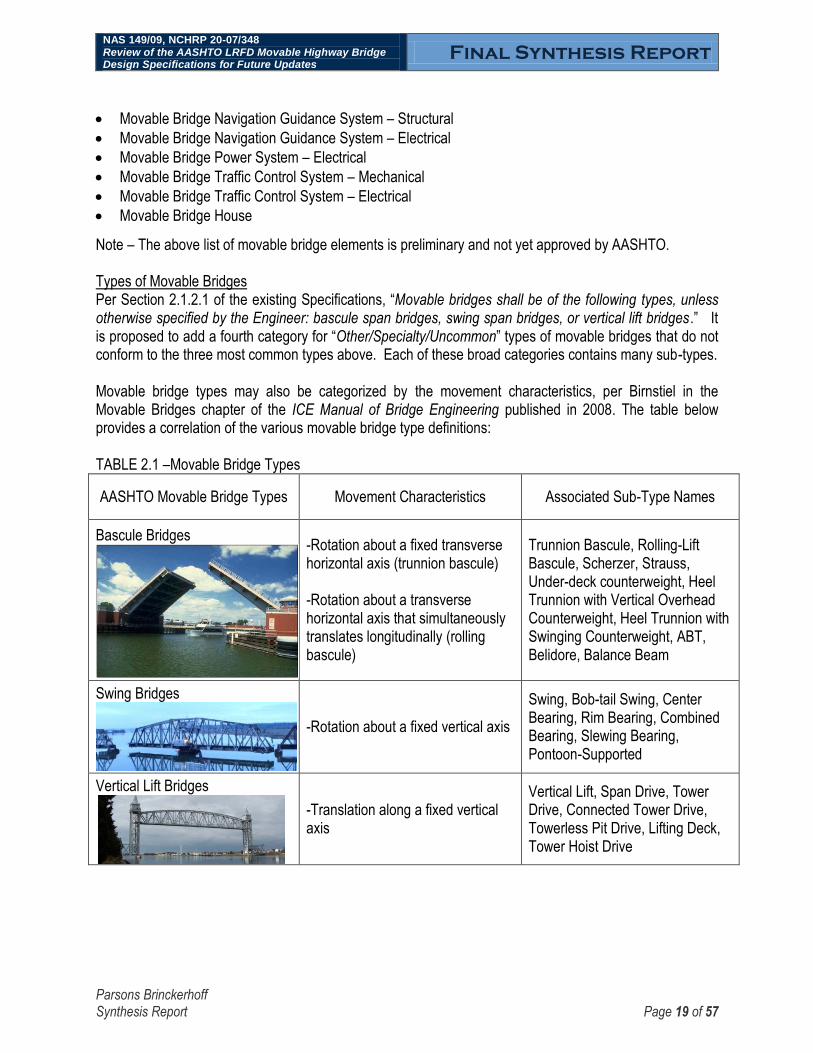
Note – The above list of movable bridge elements is preliminary and not yet approved by AASHTO. Types of Movable Bridges Per Section 2.1.2.1 of the existing Specifications, “Movable bridges shall be of the following types, unless otherwise specified by the Engineer: bascule span bridges, swing span bridges, or vertical lift bridges.” It is proposed to add a fourth category for “Other/Specialty/Uncommon” types of movable bridges that do not conform to the three most common types above. Each of these broad categories contains many sub-types. Movable bridge types may also be categorized by the movement characteristics, per Birnstiel in the Movable Bridges chapter of the ICE Manual of Bridge Engineering published in 2008. The table below provides a correlation of the various movable bridge type definitions: TABLE 2.1 –Movable Bridge Types
AASHTO Movable Bridge Types Movement Characteristics Associated Sub-Type Names
Bascule Bridges
-Rotation about a fixed transverse horizontal axis (trunnion bascule) -Rotation about a transverse horizontal axis that simultaneously translates longitudinally (rolling bascule)
Trunnion Bascule, Rolling-Lift Bascule, Scherzer, Strauss, Under-deck counterweight, Heel Trunnion with Vertical Overhead Counterweight, Heel Trunnion with Swinging Counterweight, ABT, Belidore, Balance Beam
Swing Bridges
-Rotation about a fixed vertical axis
Swing, Bob-tail Swing, Center Bearing, Rim Bearing, Combined Bearing, Slewing Bearing, Pontoon-Supported
Vertical Lift Bridges
-Translation along a fixed vertical axis
Vertical Lift, Span Drive, Tower Drive, Connected Tower Drive, Towerless Pit Drive, Lifting Deck, Tower Hoist Drive
NAS 149/09, NCHRP 20-07/348 Review of the AASHTO LRFD Movable Highway Bridge Design Specifications for Future Updates
Final Synthesis Report
Parsons Brinckerhoff Synthesis Report Page 20 of 57
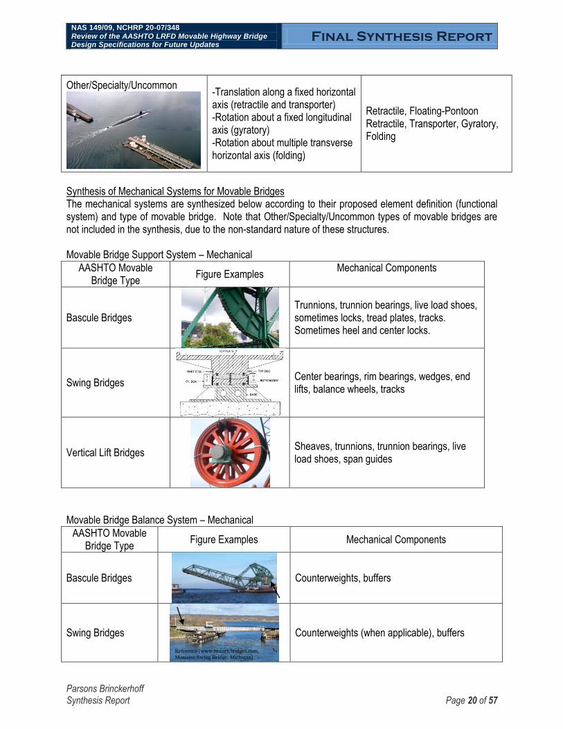
Other/Specialty/Uncommon
-Translation along a fixed horizontal axis (retractile and transporter) -Rotation about a fixed longitudinal axis (gyratory) -Rotation about multiple transverse horizontal axis (folding)
Retractile, Floating-Pontoon Retractile, Transporter, Gyratory, Folding
Synthesis of Mechanical Systems for Movable Bridges The mechanical systems are synthesized below according to their proposed element definition (functional system) and type of movable bridge. Note that Other/Specialty/Uncommon types of movable bridges are not included in the synthesis, due to the non-standard nature of these structures. Movable Bridge Support System – Mechanical
AASHTO Movable Bridge Type
Figure Examples Mechanical Components
Bascule Bridges
Trunnions, trunnion bearings, live load shoes, sometimes locks, tread plates, tracks. Sometimes heel and center locks.
Swing Bridges
Center bearings, rim bearings, wedges, end lifts, balance wheels, tracks
Vertical Lift Bridges
Sheaves, trunnions, trunnion bearings, live load shoes, span guides
Movable Bridge Balance System – Mechanical
AASHTO Movable Bridge Type
Figure Examples Mechanical Components
Bascule Bridges
Counterweights, buffers
Swing Bridges
Counterweights (when applicable), buffers
Reference [www.historicbridges.com,
Manistee Swing Bridge, Michigan]

NAS 149/09, NCHRP 20-07/348 Review of the AASHTO LRFD Movable Highway Bridge Design Specifications for Future Updates
Final Synthesis Report
Parsons Brinckerhoff Synthesis Report Page 21 of 57
Vertical Lift Bridges
Counterweights, auxiliary counterweights, counterweight ropes, balance chains, rope equalizing devices, buffers
Movable Bridge Drive System – Mechanical
AASHTO Movable Bridge Type
Figure Examples Mechanical Components
Bascule Bridges
Electric motors, hydraulic power units, internal combustion engines, manual capstans, couplings, clutches, keys, gearboxes, open gearing, brakes, shafts, shaft bearings, keys, fasteners, hydraulic piping, hydraulic motors, hydraulic cylinders, operating ropes, drums, deflection sheaves, machinery supports, wire ropes
Swing Bridges
Vertical Lift Bridges
Movable Bridge Control System – Mechanical
AASHTO Movable Bridge Type
Figure Example Mechanical Components
Bascule Bridges
Mechanical and hydraulic levers, actuators, or cables used to govern the operation of the
movable span.
Swing Bridges
Vertical Lift Bridges

NAS 149/09, NCHRP 20-07/348 Review of the AASHTO LRFD Movable Highway Bridge Design Specifications for Future Updates
Final Synthesis Report
Parsons Brinckerhoff Synthesis Report Page 22 of 57
Movable Bridge Interlocking System – Mechanical
AASHTO Movable Bridge Type
Figure Example Mechanical Components
Bascule Bridges
Locks, Centering Devices Swing Bridges
Vertical Lift Bridges
Movable Bridge Traffic Control System – Mechanical
AASHTO Movable Bridge Type
Figure Example Mechanical Components
Bascule Bridges
Warning Gates, Barrier Gates
Swing Bridges
Vertical Lift Bridges
A discussion of common types of mechanical drive systems for movable bridges, including pros and cons, is below: Electro-Mechanical-Gear-Type- Uses electric motor prime movers with enclosed gearboxes, open gearing, shafts, shaft couplings, shaft bearings, and brakes. Typically the power is transferred to the movable span using an open spur gear pinion engaging a rack. This is the most common type of movable bridge mechanical operating system in the United States.
Pros: simple and reliable; low maintenance; tolerant of poor or negligent maintenance; can be designed with redundancy; many potential fabricators to bid the work
Cons: high relative initial cost; typically involves a lengthy and exacting construction phase for machinery alignment

NAS 149/09, NCHRP 20-07/348 Review of the AASHTO LRFD Movable Highway Bridge Design Specifications for Future Updates
Final Synthesis Report
Parsons Brinckerhoff Synthesis Report Page 23 of 57
Hydraulic with Cylinders- Uses a hydraulic power unit (HPU), typically consisting of electric motors, fluid reservoir, pumps, and a directional valve. The HPU supplies pressurized fluid to hydraulic cylinders that provide the force to operate the span.
Pros: low relative initial cost; shop fabrication and testing can minimize field installation time.
Cons: requires frequent and sophisticated maintenance; relatively few potential fabricators to bid the work;
Hydraulic with Motors- Uses an HPU to supply pressurized fluid to hydraulic motors that directly drive an open spur gear engaging a rack.
Pros: compact size and flexible layout positioning are possible.
Cons: requires frequent and sophisticated maintenance; lower efficiency when compared with electro-mechanical or hydraulic cylinder systems; relatively few potential fabricators to bid the work.
Pneumatic- A pneumatic motor with a disconnecting coupling are often used as an auxiliary mover for movable bridges.
Pros: inexpensive; low maintenance; high torque; can be powered using a diesel air compressor when electric power is not available; simple controls consisting of a single lever-operated valve.
Cons: Loud; slow operation; generally suitable only as an auxiliary mover
Human-Powered- Uses a capstan or crank, coupled with a large gear ratio, to facilitate human powered operation.
Pros: inexpensive
Cons: very slow operation; only suitable as an auxiliary mover or for very infrequently operated, small spans

NAS 149/09, NCHRP 20-07/348 Review of the AASHTO LRFD Movable Highway Bridge Design Specifications for Future Updates
Final Synthesis Report
Parsons Brinckerhoff Synthesis Report Page 24 of 57
Synthesis of Electrical Systems for Movable Bridges The electrical systems are synthesized below according to their proposed element definition (functional system) and type of movable bridge. Note that Other/Specialty/Uncommon types of movable bridges are not included in the synthesis, due to the non-standard nature of these structures. Movable Bridge Control System – Electrical
AASHTO Movable Bridge Type
Figure Example Electrical Components
Bascule Bridges
Drive motor controllers, motor control centers, control console, relays, contactors, programmable logic controller, limit switches, pilot lights, hand switches, instrumentation, sensors, position transmitters, inclinometers, networks, cables, conductors, submarine cables, aerial cables, wireless modem transmitters/receivers, conduit/raceways, cable trays, electronic firmware, logic programming.
Swing Bridges
Vertical Lift Bridges
Movable Bridge Interlocking System – Electrical
AASHTO Movable Bridge Type
Figure Example Electrical Components
Bascule Bridges
Emergency stop; over-speed; over-skew; over-travel; traffic signals current relays; operating sequences; critical bridge component position verification; brake position switches; lock position switches; span position switches; gate position switches; bypass switches; control systems.
Swing Bridges
Vertical Lift Bridges

NAS 149/09, NCHRP 20-07/348 Review of the AASHTO LRFD Movable Highway Bridge Design Specifications for Future Updates
Final Synthesis Report
Parsons Brinckerhoff Synthesis Report Page 25 of 57
Movable Bridge Navigation Guidance System – Electrical
AASHTO Movable Bridge Type
Figure Example Electrical Components
Bascule Bridges
Green/red channel lights, red pier lights, red fender lights, red clearance lights, vertical clearance gauge lights, aviation beacons, marine radios, horn/siren.
Swing Bridges
Vertical Lift Bridges
Movable Bridge Electrical Power System – Electrical
AASHTO Movable Bridge Type
Figure Example Electrical Components
Bascule Bridges
Electrical service equipment, meters, disconnect switches, motor control centers, standby generators, automatic transfer switches, transformers, uninterruptable power supplies, power distribution panels, main circuit breakers, branch circuit breakers, fuses, overcurrent protective relays, ground fault relays, motor circuit protectors, conductors, feeders, cables, submarine cables, aerial cables, conduit/raceways, cable trays.
Swing Bridges
Vertical Lift Bridges
Movable Bridge Traffic Control System – Electrical
AASHTO Movable Bridge Type
Figure Example Electrical Components
Bascule Bridges
Public address system w/loudspeakers, traffic signal heads, flashing warning signs, traffic warning gates, traffic barrier gates, resistance/yielding barriers, pedestrian walk/don‟t walk signals, pedestrian warning gates, pedestrian retaining gates, camera systems.
Swing Bridges
Vertical Lift Bridges

NAS 149/09, NCHRP 20-07/348 Review of the AASHTO LRFD Movable Highway Bridge Design Specifications for Future Updates
Final Synthesis Report
Parsons Brinckerhoff Synthesis Report Page 26 of 57
Discussion of Electrical Control Systems for Movable Bridges A detailed discussion of the common types of control systems for movable bridges, including pros and cons, is below. Relay Based Controls- Uses hard-wired electro-mechanical relays to execute bridge operator commands and automatic control logic for bridge system operations.
Pros: simple and reliable; long life, low maintenance; can be designed with redundancy and triplication for critical safety interlocks; immune to electromagnetic noise; not sensitive to power surges.
Cons: may be difficult to troubleshoot large or complex systems; difficult to implement real-time computations; higher initial capital cost for larger, high-relay count systems; requires more conductors; difficult to configure for data logging, trending, and alarming; not compatible with wireless controls; difficult to configure for remote monitoring; risk of lengthy shop testing; shortage of engineers with relay design skills/experience; spare parts may be difficult to obtain.
Programmable Logic Controllers (PLC) - Uses industrial hardened microprocessor based systems to execute bridge operator commands, automatic control logic, data logging and alarming, and remote monitoring for bridge system operations. PLCs use software operating programs to execute logic commands and control system communications. Virtual logic in the PLC is connected to real world devices such as operator console switches, indicating lights, motors, valves and other devices using hard-wired input/output communication cards.
Pros: may be easier to troubleshoot large or complex systems (depending on programming techniques and annotation); easy to commission and reconfigure; standard ladder logic programming capability; provides remote monitoring capabilities; easy to configure data logging, trending, and alarming; compatible with wireless controls; can be designed with redundancy and triplication for critical safety interlocks; uses network communications and fewer conductors.
Cons: requires trained technical staff for maintenance; electronics tend to become obsolete as newer versions are manufactured; programming can become cryptic and difficult to follow if not properly annotated or when ladder logic formats are not used; sensitive to power surges and lightning strikes; sensitive to electromagnetic noise from a.c. vector type variable frequency speed control drives.
Direct Digital Control (DDC) - Uses industrial hardened computers in a direct digital configuration to execute bridge operator commands, automatic control logic, data logging and alarming, and remote monitoring for bridge system operations. DDC uses software operating programs to execute logic commands and control system communications. Virtual logic in the DDC is connected to real world devices such as operator console switches, indicating lights, motors, valves and other devices using hard-wired input/output communication cards or modules. The difference between PLCs and DDC systems are the operating hardware, firmware and software. PLCs are specifically designed strictly for industrial controls in industrial environments, and are designed for maintenance by electricians. DDC systems are not specific to any single use, and are designed for maintenance by information technicians.
Pros: easy to reconfigure; provides remote monitoring capabilities; easy to configure data logging, trending, and alarming; compatible with wireless controls.

NAS 149/09, NCHRP 20-07/348 Review of the AASHTO LRFD Movable Highway Bridge Design Specifications for Future Updates
Final Synthesis Report
Parsons Brinckerhoff Synthesis Report Page 27 of 57
Cons: requires trained technical staff for maintenance; does not use standard ladder logic programming; network performance is critical to control; difficult to design with redundancy and triplication for critical safety interlocks; electronics tend to become obsolete as newer versions are manufactured; sensitive to power surges and lightning strikes; sensitive to electromagnetic noise from a.c. vector type variable frequency speed control drives.
Hybrids- combined PLC and relay based system. Can provide the best of both systems or the worst of both systems depending on the configuration, integration, and programming. Preferred by some movable bridge owners and operators because manual operating modes are provided for general maintenance activities, and safety interlocks and automation are provided for day to day operation. All control system activity can be logged, alarmed, and remotely monitored.
Pros: provides inherent redundancy and reliability.
Cons: higher initial costs; requires more control cabinet and control console space; requires more conductors than PLC alone.
Interlocking: includes the mechanical lock components and electrical components and underlying logic that provide for the proper sequence of bridge operation. Navigational guidance: includes the navigational lighting, marine radios, and signage. Traffic control: includes barriers with structural, mechanical, and electrical components; signage; roadway markings; lighting; intercoms, camera systems; and more.

NAS 149/09, NCHRP 20-07/348 Review of the AASHTO LRFD Movable Highway Bridge Design Specifications for Future Updates
Final Synthesis Report
Parsons Brinckerhoff Synthesis Report Page 28 of 57
Discussion of Electrical Motor Drive Systems for Movable Bridges A detailed discussion of the present types of motor drive systems for movable bridges, including pros and cons, follows. Speed and torque control for drive motors can be accomplished using several different methods. Options are based on the type of drive motor being used including AC induction, AC wound rotor, or DC. These types of motors are typically used among the different types of movable bridge drive systems. The motor speed and torque can be controller using electronic based drives, or hardwired relay, contactor and resistor based circuits. Non-electronic based drive motor controls generally require operator experience for optimum control. Operator knowledge of each structure‟s dynamic characteristics during different weather conditions become very important to moving, stopping and seating the span. The electronic based drives are capable of providing precise speed and torque control of span drive motors. They can be programmed and tuned for optimum control during all conditions with minimal operator intervention. There has been a great deal of progress and improvements with electronic drive technology over the past 50 years. This trend is expected to continue, and the present electronic drive systems will become obsolete as electronic technology advances. Motor drives systems presently in use include the following: DC Motors- a. Hardwired relay, contactor, resistor, using manual control. Pros: simple, reliable, low cost; long life, low maintenance; high torque at low speeds, true dynamic
braking, do not generate harmonic noise, immune to electromagnetic noise; not sensitive to power surges, retrofit to use existing DC motors.
Cons: require operator experience and intervention, cannot be tuned for optimal performance, not
conducive for speed or torque feedback control, high cost for new motors.
b. SCR (silicone controlled rectifier) digital electronic drive, fully regenerative, four quadrant, programmable automatic or manual control, with speed and torque feedback. Pros: fully regenerative, true dynamic braking, precise programmable speed and torque control, high
torque at low speeds, excellent seating control, retrofit to use existing DC motors. Cons: high initial cost, prone to electronic obsolescence, generates harmonic noise, motor cooling
blowers may be needed, maintenance requires highly trained technicians, high cost for new motors.
AC Wound Rotor Motors- a. Hardwired relay, contactor, resistor, using manual control. Pros: simple, reliable, low cost; long life, low maintenance; high torque at low speeds, do not generate
harmonic noise, immune to electromagnetic noise; not sensitive to power surges, retrofit to use existing AC wound rotor motors.
Cons: require operator experience and intervention, cannot be tuned for optimal performance, not
conducive for speed or torque feedback control, high cost for new motors.

NAS 149/09, NCHRP 20-07/348 Review of the AASHTO LRFD Movable Highway Bridge Design Specifications for Future Updates
Final Synthesis Report
Parsons Brinckerhoff Synthesis Report Page 29 of 57
b. Variable voltage SCR analog electronic drive, secondary resistors, fully regenerative, four quadrant, automatic or manual control, with speed and torque feedback. Pros: fully regenerative, good torque control, high torque at low speeds, excellent seating control, do
not generate harmonic noise, retrofit to use existing AC wound rotor motors. Cons: high initial cost, prone to electronic obsolescence (only one known manufacturer remains),
maintenance requires highly trained technicians, high cost for new motors.
AC Induction Motors- a. Variable frequency flux vector electronic drive, with braking resistors. Pros: excellent speed and torque control, high torque at low speeds, excellent seating control. Cons: high initial cost, prone to electronic obsolescence, generates harmonic noise, motor cooling
blowers may be needed, maintenance requires highly trained technicians, high cost for specially designed inverter duty motors.

NAS 149/09, NCHRP 20-07/348 Review of the AASHTO LRFD Movable Highway Bridge Design Specifications for Future Updates
Final Synthesis Report
Parsons Brinckerhoff Synthesis Report Page 30 of 57
TASK 3 – DISCUSS THE APPLICATION OF RELIABILITY-BASED DESIGN TO MECHANICAL, ELECTRICAL, AND TRAFFIC/MARINE SAFETY SYSTEMS FOR MOVABLE BRIDGES
Discussion of the development of AASHTO LRFD for bridge structures LRFD is a calibrated, reliability-based method of structural bridge design that aims for a uniform level of safety for a variety of bridge types, materials, span lengths, and under various load combinations and limit states. There are four structural limit states: Service, Strength, Fatigue & Fracture, and Extreme Events. Each of the of the limit states are considered to have equal importance and, per the Specifications Section 1.3.2, shall satisfy the below equation.
The key to calibrating the Specifications, performed as part of NCHRP Project 12-33, was to determine a suitable Reliability Index (β). The Reliability Index is relatable to the probability of failure. Once the value for the Reliability Index was agreed upon, it was used as a basis for load factors (γ) and resistance factors (Φ). The goal in setting the Reliability Index was to obtain bridge performance that was tolerable to society, both in terms of safety and economics. The lower the Reliability Index, the more likely that component and bridge failure will occur. The higher the Reliability Index, the more material and expense that will be required for construction. For bridge structures, AASHTO selected a Reliability Index of 3.5 [standard deviations from the mean of resistance (R) minus loads (Q)], on a component basis. For a ductile, redundant structure, this works out to a system (a.k.a. individual bridge) reliability of over 5. In other words, for components (members) and systems (bridges), the probability of failure is approximately 2 in 10,000 and 1 in 1,000,000, respectively. This compares favorably with the nearly 600,000 bridges listed in the Federal Highways Administration (FHWA) National Bridge Inventory. The intent of moving the AASHTO Specifications from WSD to LRFD based design was such that new bridge designs would be more uniform with regards to safety and probability of failure. In general, there was no intent for the bridges to become heavier or lighter, more expensive or less safe. However, while this

NAS 149/09, NCHRP 20-07/348 Review of the AASHTO LRFD Movable Highway Bridge Design Specifications for Future Updates
Final Synthesis Report
Parsons Brinckerhoff Synthesis Report Page 31 of 57
approach is suitable for structures for which there is a large database that can be used to calibrate load and resistance factors, that is not the case for the key elements of a movable bridge: the mechanical ,electrical, and traffic/marine safety systems. As discussed below a reliability approach that is is similar to that used to characterize structural systems but differs in application is proposed. Discussion of applying reliability-based design to mechanical, electrical, and traffic/marine safety systems for movable bridges
Below is a list of key questions for mechanical, electrical, and traffic/marine safety systems:
- How to define failure?
- What, historically, have been the causes and consequences of failure?
- What additional (non-historical) causes for potential failure can be anticipated? What are the associated consequences?
- What is the probability of failure of existing systems, designed per existing AASHTO and international standards? Is this acceptable?
- How can maintenance by the owner be considered as part of the level of reliability in design?
Each of these key questions is discussed in more detail below. How to define failure? Webster‟s dictionary includes several definitions of failure, including: “1.c: a fracturing or giving way under stress <structural failure>” This is likely the definition that the general public has in mind when thinking of the possibility of a bridge failure. This definition is applicable to three of the four limit states found in the AASHTO LRFD Bridge Design Specifications: the Strength, Fatigue & Fracture, and Extreme Events limit states. However, the above definition is inadequate to describe structural failures of fixed bridges, with regards to the Serviceability limit state. The serviceability limit state relates to the human comfort of bridge users, particularly with regards to vibrations and deflections of the bridge structure. The above definition is also inadequate to describe many types of failures of movable bridge mechanical, electrical, and traffic/marine safety systems. For movable bridges, a more relevant definition of failure, found in Webster‟s dictionary includes: “1.b: (1) a state of inability to perform a normal function; (2) an abrupt cessation of normal functioning” The normal functions of a movable bridge include opening to allow navigable vessels to pass through the channel, and closing to allow vehicles, pedestrians, and bicycles to pass upon the roadway. A fault that renders a movable bridge unable to service any of these modes of transportation can be considered a failure. What, historically, have been the causes and consequences of failure?
NAS 149/09, NCHRP 20-07/348 Review of the AASHTO LRFD Movable Highway Bridge Design Specifications for Future Updates
Final Synthesis Report
Parsons Brinckerhoff Synthesis Report Page 32 of 57
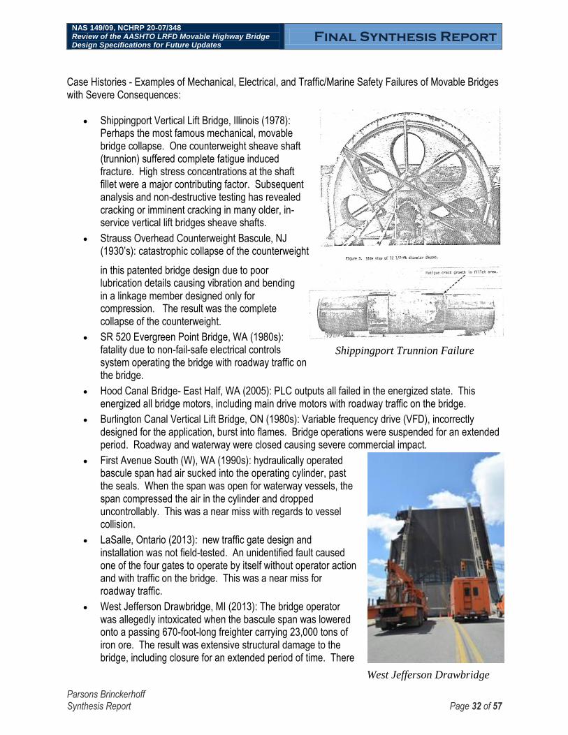
West Jefferson Drawbridge
DrafDraDDDrawbridge
Shippingport Trunnion Failure
Case Histories - Examples of Mechanical, Electrical, and Traffic/Marine Safety Failures of Movable Bridges with Severe Consequences:
Shippingport Vertical Lift Bridge, Illinois (1978): Perhaps the most famous mechanical, movable bridge collapse. One counterweight sheave shaft (trunnion) suffered complete fatigue induced fracture. High stress concentrations at the shaft fillet were a major contributing factor. Subsequent analysis and non-destructive testing has revealed cracking or imminent cracking in many older, in-service vertical lift bridges sheave shafts.
Strauss Overhead Counterweight Bascule, NJ (1930‟s): catastrophic collapse of the counterweight
in this patented bridge design due to poor lubrication details causing vibration and bending in a linkage member designed only for compression. The result was the complete collapse of the counterweight.
SR 520 Evergreen Point Bridge, WA (1980s): fatality due to non-fail-safe electrical controls system operating the bridge with roadway traffic on the bridge.
Hood Canal Bridge- East Half, WA (2005): PLC outputs all failed in the energized state. This energized all bridge motors, including main drive motors with roadway traffic on the bridge.
Burlington Canal Vertical Lift Bridge, ON (1980s): Variable frequency drive (VFD), incorrectly designed for the application, burst into flames. Bridge operations were suspended for an extended period. Roadway and waterway were closed causing severe commercial impact.
First Avenue South (W), WA (1990s): hydraulically operated bascule span had air sucked into the operating cylinder, past the seals. When the span was open for waterway vessels, the span compressed the air in the cylinder and dropped uncontrollably. This was a near miss with regards to vessel collision.
LaSalle, Ontario (2013): new traffic gate design and installation was not field-tested. An unidentified fault caused one of the four gates to operate by itself without operator action and with traffic on the bridge. This was a near miss for roadway traffic.
West Jefferson Drawbridge, MI (2013): The bridge operator was allegedly intoxicated when the bascule span was lowered onto a passing 670-foot-long freighter carrying 23,000 tons of iron ore. The result was extensive structural damage to the bridge, including closure for an extended period of time. There

NAS 149/09, NCHRP 20-07/348 Review of the AASHTO LRFD Movable Highway Bridge Design Specifications for Future Updates
Final Synthesis Report
Parsons Brinckerhoff Synthesis Report Page 33 of 57
was minor damage to the vessel.
Many movable bridge failures are less severe than the above case study examples and go undocumented. For example, temporary issues where a movable bridge gets stuck due to debris or heat. Another example would be when a movable bridge experiences a power failure, if there is no functioning auxiliary source.
The failure of a structural bridge component typically risks severe or catastrophic consequences. The same goes for the failure of components of the mechanical support or balancing functional systems. Likewise, safety of the traveling public, both roadway and marine, is of the utmost importance. Therefore, failure of traffic/marine safety systems must also be considered to risk severe consequences. For many mechanical and electrical drive components, the consequences of failure may not risk catastrophic collapse. However, the consequences can still be quite severe. For example a fault that causes unexpected span motion may result in the death or injury of land-based bridge users or mariners. The social and economic consequences of a movable span temporarily rendered immobile differ based on the “performance criteria” of the bridge. Similarly, in Section 3.3 of the Specifications for seismic design, bridges are designated with a performance criterion of “critical”, “essential”, or “other” depending on the safety or economic impacts to the surrounding region if the bridge is rendered unusable by traffic or navigation temporarily or for an extended period of time.
Typical traffic barrier gates are designed to physically stop speeding vehicles and prevent them from plunging off the open movable bridge and into the channel. However, after serving this function the barrier gates generally require repairs before they can be returned to service.
What additional (non-historical) causes for potential failure can be anticipated? What are the associated consequences? None identified at this time. What is the probability of failure of existing systems, designed per existing AASHTO and international standards? The AASHTO LRFD Bridge Design Specifications is based upon a reliability index of 3.5. This reliability index applies to fixed bridge structures, not to movable bridge mechanical, electrical, or traffic/marine safety systems. Per the Dutch standard NEN 6786/A1 Requirements for Design of Movable Bridges, “the minimum reliability index (f3) is:
- Ultimate Limit State, when Wind Load controls: f3 = 2.6
- Ultimate Limit State, if other loads control: f3 = 3.6
- Serviceability Limit State: f3 = 0.5 ”
The reliability index specified in the Dutch NEN standard also applies to movable bridge machinery, in
addition to structures.

NAS 149/09, NCHRP 20-07/348 Review of the AASHTO LRFD Movable Highway Bridge Design Specifications for Future Updates
Final Synthesis Report
Parsons Brinckerhoff Synthesis Report Page 34 of 57
The current AASHTO LRFD Movable Highway Bridge Design Specifications uses working stress design and does not currently use probability-based, reliability-based methodology. The existing Specifications in Section 6.4.1.1 indicate four limit states for bridge machinery: service, fatigue, overload, and extreme event. However, the machinery design sections are based on allowable working stress design, not these limit states. The commentary says “As of this writing (2006), reliability-based design at the strength limit state is not possible given the dearth of necessary data.”
How can maintenance by the owner be considered as part of the level of reliability in design? Movable bridges are maintenance intensive, particularly with regards to mechanical and electrical equipment. The actual in-service reliability experienced by a given movable bridge is highly dependent on the quality of the maintenance. In theory, for the same level of reliability, movable bridge owners with rigorous and effective maintenance programs could have new movable bridge equipment built to less robust designs, when compared with owners that neglect maintenance. However, implementing such a theory into the AASHTO design specifications poses difficulties, particularly with regards to the potential hierarchical categorization of owners according to quality of maintenance. In addition, even an over-designed movable bridge may prove unreliable if maintenance is neglected.

NAS 149/09, NCHRP 20-07/348 Review of the AASHTO LRFD Movable Highway Bridge Design Specifications for Future Updates
Final Synthesis Report
Parsons Brinckerhoff Synthesis Report Page 35 of 57
Proposed approach for applying reliability-based design to mechanical, electrical, and traffic/marine safety systems for movable bridges
The reliability approach used for nonstructural systems is similar to that used to characterize structural systems but differs a bit in application. When quantifying the reliability of a structural system, one assesses the likelihood of failure by determining the probability of a simultaneous overload and understrength.
Independently, the probability of an overload is handled by using load factors, , and the probably of a
component understrength is handled by using resistance factors, . Redundancy in the structural system - having multiple load paths by employing a system with parallel members, employing members with increased ductility, and adding structural redundancy like continuous beams - is addressed indirectly by
using load modifiers, . Addressing the influences of redundancy, ductility, and participation of secondary load paths on structural reliability more directly than using a load modifier is challenging because of the limitations associated with analysis and modeling those influences. In nonstructural systems, however, system redundancy can be directly quantified more readily. Engineering systems are often made up of components that are arranged either in series or in parallel. In a system of components arranged in series, the failure of any one component will result in the failure of the system whereas in a system of parallel components, the failure of all of the components is required for a system failure. While the reliability, R, of each component is often determined by the component manufacturer, it is left to the engineer to determine the reliability of the system that results when the components are combined. Component reliabilities are often quantified in terms of failure rate for a given time interval, t, or in terms of a mean time to failure. Generally, as the design life of a component increases, the failure rate also increases and the reliability is reduced. As a result, the reliability of a system is also dependent on the design life. Assumptions about the maintenance of the system and its components must be made in order to quantify system reliability. Examples of maintenance include things such as lubrication of trunnions, routine servicing of gasoline or diesel generators, and changing light bulbs in traffic control signals. In terms of structural reliability, that maintenance would be analogous to routine bridge inspections on an annual or semi-annual basis wherein it is assumed that a small crack or similar issue would be discovered and corrected before it became catastrophic. In an analysis to determine system reliability, engineering systems are often modeled as combinations of single components and/or subsystems made up of components arranged in serial or parallel. This is done so that a large complex problem can be broken into smaller problems that can be addressed by applying theoretical formulas. In some cases a parallel subsystem may be made up of identical components such as the case of redundant control systems. In other cases, a parallel subsystem may be made up of non-identical components with different reliabilities, such as a power system made of either electrical supplied by utility service or by an electric generator. The reliability of both subsystems would be computed differently. Reliability, R, varies between 0 and 1, with 1 indicating 100% live components. For further information and derivations of the mathematical formulas found below, please refer to “Reliability Theory and Practice” by Igor Bazovsky and “Understanding Series and Parallel Systems Reliability” by Jorge Luis Romeu, respectively reference numbers 28 and 29 in the Task 1 – Literature Review herein.

NAS 149/09, NCHRP 20-07/348 Review of the AASHTO LRFD Movable Highway Bridge Design Specifications for Future Updates
Final Synthesis Report
Parsons Brinckerhoff Synthesis Report Page 36 of 57
The reliability of a component during any time period can be expressed as:
tR e Where:
- R varies between 0 and 1, with 1 indicating 100% live components
- = proportional failure rate of a component
- t = time
The mean time to failure of a system of components in series:
1
s
Where:
- u = mean time to failure (MTTF) of a system
- s = proportional failure rate of the system
The reliability of a system of components in series is:
... ...s 1 2 i nR R R R R
Where: - Rs is the system reliability
- Rs = proportional failure rate of a system s = i
- R1, R2, Ri are the reliabilities of the system components
The reliability of a system of components in parallel is:
21 1 1 ... 1 ... 1s 1 i nR R R R R
Where: - R1, R2, Ri are the reliabilities of the system components
In the context of a movable bridge, the electrical supply subsystem, control subsystem, traffic control subsystem, electrical motors and lift mechanisms, and the subsystem of trunnions, sheaves, or ropes would be combined in series. As an example, the complete loss of power as a result of the simultaneous failure of the electric utility and backup generator would represent a subsystem failure. The reliability of this subsystem would be quantified by modeling it as a parallel subsystem of non-identical components. Since the failure of this

NAS 149/09, NCHRP 20-07/348 Review of the AASHTO LRFD Movable Highway Bridge Design Specifications for Future Updates
Final Synthesis Report
Parsons Brinckerhoff Synthesis Report Page 37 of 57
subsystem would prevent the operation of the bridge, this subsystem would be treated as acting in parallel with the other subsystems forming the overall system. An example reliability block diagram for sub-systems of a movable bridge is shown below.
Note that while redundancy theoretically increases reliability, it also increases complexity. This added complexity can make troubleshooting and repair of faults more difficult and time consuming. A simplified example of calculating the system reliability of two different layouts of operating machinery are provided below. Future research is required in order to establish the reliability (R) of common movable bridge components. For the purpose of the simplified example, the below reliability numbers will be used.
Component Mean Time to Failure
( or MTTF)
Reliability (R) when t = 1 year
Motor Say 20 years 0.95
Gearbox Say 30 years 0.97
Open Gearing Say 40 years 0.98
Floating Shaft Say 100 years
0.99

NAS 149/09, NCHRP 20-07/348 Review of the AASHTO LRFD Movable Highway Bridge Design Specifications for Future Updates
Final Synthesis Report
Parsons Brinckerhoff Synthesis Report Page 38 of 57
Simplified Example – Operating System #1
Motor Motor
Gearbox Open Gearing
Floating Shaft
Plan View
Reliability Schematic
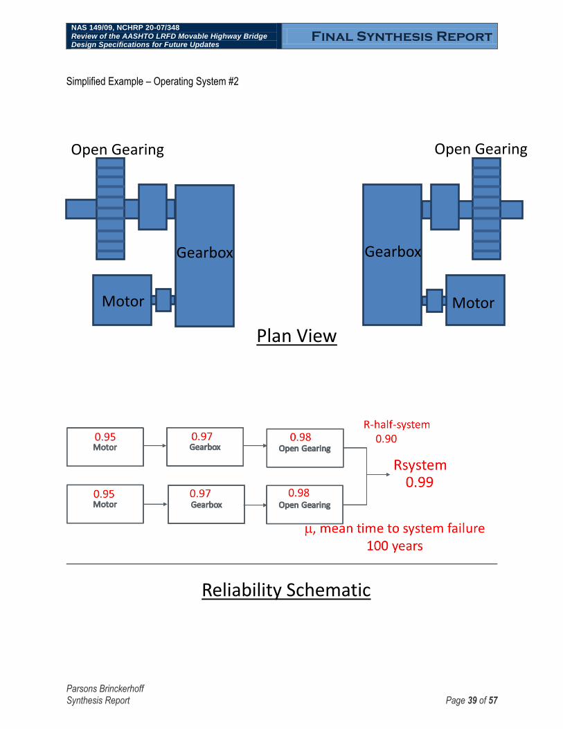
NAS 149/09, NCHRP 20-07/348 Review of the AASHTO LRFD Movable Highway Bridge Design Specifications for Future Updates
Final Synthesis Report
Parsons Brinckerhoff Synthesis Report Page 39 of 57
Simplified Example – Operating System #2
Motor Motor
Gearbox
Open Gearing
Gearbox
Open Gearing
Plan View
Reliability Schematic

NAS 149/09, NCHRP 20-07/348 Review of the AASHTO LRFD Movable Highway Bridge Design Specifications for Future Updates
Final Synthesis Report
Parsons Brinckerhoff Synthesis Report Page 40 of 57
Note that in the above simplified examples, the mean time to failure of Operating System #2 of 100 years is an order of magnitude greater than the mean time to failure of Operating System #1 of 11 years. This is due to different the layout or configuration of the systems, not due to the sizing of individual components, for which identical reliabilities are assumed. Each component in Operating System #2 is fully redundant, which greatly increases the system reliability. The existing AASHTO LRFD Movable Highway Bridge Design Specifications provides guidance for sizing components, but does not provide guidance regarding the selection of system layout or configuration. The reliability approach proposed herein will allow the revised Specifications to guide system layout and configuration. For future research it will be necessary for the Specifications to not only provide means to calculate system reliability, but also provide acceptance criteria. The suggested approach is to differentiate between “Critical” movable bridges that have significant traffic or navigation openings, as opposed to “Non-Critical” movable bridges. Movable bridges identified as “Critical” will be required to achieve significantly more rigorous reliability standards. The below table is provides preliminary recommendations regarding movable bridge reliability acceptance criteria. Further research is needed to refine and verify this proposed approach.
Movable Bridge Reliability Acceptance Criteria
Mean Time to Failure
( or MTTF)
Reliability (R) when t = 1 year
Critical Movable Bridges with:
Average Daily Traffic (ADT) > 10,000 or
Vessel Openings > 300 per year
Say 100 years 0.99
Other, Non-Critical Movable Bridges Say 20 years 0.95
NAS 149/09, NCHRP 20-07/348 Review of the AASHTO LRFD Movable Highway Bridge Design Specifications for Future Updates
Final Synthesis Report
Parsons Brinckerhoff Synthesis Report Page 41 of 57
ELECTRICAL SYSTEMS
The reliability of electrical systems can be mathematically modeled using the same methods as discussed above. However, additional considerations particular to electrical systems, such as obsolescence, are discussed below.
Electrical power system designs should provide reliable and safe service for 30 years or more. Eventually, revisions to the governing design standards and codes will make the power systems obsolete. Power system conductors, raceway, and motors will physically provide service for 30 to 50 years. After 10 to 20 years, spare parts may become difficult to locate based on the movable bridge industry experience over the past 40 years.
Control system designs should provide reliable service for 20 years or more. Control system components tend to become obsolete faster than power system equipment. Electromechanical relays and non-electronic based components are less prone to becoming obsolete. Other than obsolescence, the control system equipment can provide service for 20 years or more.
Electrical and control system design requires fault tree type analysis, and mean time to failure analysis when integrating the systems. All instances should be avoided or corrected where a single point failure or single component failure will render a system non-operational. Any non-fail-safe controls must be corrected. The fault tree analysis can be kept simple as long as it covers all of the “what if” scenarios. The correct balance of fault tolerance and redundancy must be used in design. Close coordination of both concept design and detailed design must occur among all key disciplines- structural, mechanical, electrical, and civil. For example, if a system is using two drive motors, then a differential gear box may be replaced with electronic synchronized motor drives for load sharing. However, doing so may reduce the overall fault tolerance of the operating system.
Reliability-based design includes providing enough details in the plans and specifications to ensure the contractor and, if applicable, systems integrator clearly know what to do. The design plans and specifications must go beyond the individual components and address details of the integrated system requirements. In some cases, details may address construction means and methods. For example, a very high quality limit switch used for a safety interlock will not function reliably if it is not positioned and mounted correctly. The design needs to clearly show this level of detail. Even with a high level of redundancy in a design, control conductors are not usually made redundant. Specify wire connectors and lugs that can withstand harsh, high vibration environments. A loose or disconnected wire can disable an entire operating system. The minimum acceptable level of installation qualifications must be specified in the design.
RELIABILITY AND BRIDGE OPERATORS
All power and control systems, as well as traffic/marine safety systems, for movable bridges require an individual (commonly referred to as an operator or bridge tender) to operate the bridge. The boiler controls and burner management industry asserts that there is “no substitute for well trained operators” when referring to system reliability and safety. Many design, interlock, and operations parallels with movable bridge power and control systems are found in NFPA 86- Standard for Ovens and Furnaces. NFPA-86 also defined the minimum acceptable level of design required for the systems it governs. The movable bridge industry could benefit from considering these definitions.

NAS 149/09, NCHRP 20-07/348 Review of the AASHTO LRFD Movable Highway Bridge Design Specifications for Future Updates
Final Synthesis Report
Parsons Brinckerhoff Synthesis Report Page 42 of 57
TASKS 4 & 5 – OUTLINE OF PROPOSED AREAS OF AASHTO LRFD MOVABLE BRIDGE DESIGN SPECIFICATIONS FOR FUTURE UPDATES
The specifications currently contain 278 pages and the following 8 sections, plus an Appendix:
Title: AASHTO LRFD Movable Highway Bridge Design Specifications (existing, 2nd Edition with Interims)
1. General Provisions 2. Structural Design 3. Seismic Design 4. Vessel Collision Considerations 5. Mechanical Design Loads and Power Requirements 6. Mechanical Design 7. Hydraulic Design 8. Electrical Design Appendix
It is proposed to condense the title and sections as follows: Title: AASHTO Movable Bridge Design Specifications (proposed) Table of Contents
1. General Provisions 2. Structural Design 3. Mechanical Design
4. Hydraulic Machinery Design 5. Electrical Design Index References
Appendix With regards to the title, it is recommended to delete “Highway” in order to better align with the title of the primary design reference for fixed bridges, AASHTO LRFD Bridge Design Specifications. Furthermore, the designation “LRFD” is proposed to be removed from the title. The reliability-based approach proposed in Task 3 above goes beyond a traditional LRFD approach with respect to the nonstructural components and systems. The development of the AASHTO LRFD Bridge Design Specifications was based upon a database that is not available for movable bridges. As an alternative, the term “LRFD” could be replaced with the term “Reliability-Based” to distinguish the specification from past versions that were based on a different underlying design philosophy. The suggested outline above will be accomplished by combining the pre-existing sections, not deleting them. For example, it is proposed to include vessel collision as a sub-section of Structural Design, rather than a stand-alone section. Seismic Design will be combined into Structural Design as it is primarily a

NAS 149/09, NCHRP 20-07/348 Review of the AASHTO LRFD Movable Highway Bridge Design Specifications for Future Updates
Final Synthesis Report
Parsons Brinckerhoff Synthesis Report Page 43 of 57
structural consideration, but where applicable it will also be specifically addressed in the mechanical and electrical sections. Note that it is proposed to add a complete Table of Contents to the beginning of the specifications. The existing specifications have a separate Table of Contents at the beginning of each part, but do not have a complete Table of Contents. It is proposed that the document will continue to use a two column document with the specifications on the left column and the commentary on the right column.
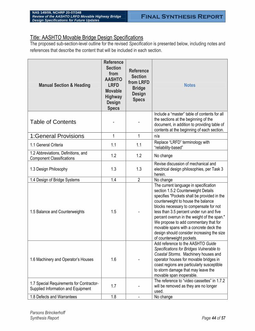
NAS 149/09, NCHRP 20-07/348 Review of the AASHTO LRFD Movable Highway Bridge Design Specifications for Future Updates
Final Synthesis Report
Parsons Brinckerhoff Synthesis Report Page 44 of 57
Title: AASHTO Movable Bridge Design Specifications The proposed sub-section-level outline for the revised Specification is presented below, including notes and
references that describe the content that will be included in each section.
Manual Section & Heading
Reference Section
from AASHTO
LRFD Movable Highway Design Specs
Reference Section
from LRFD Bridge Design Specs
Notes
Table of Contents - -
Include a “master” table of contents for all the sections at the beginning of the document, in addition to providing table of contents at the beginning of each section.
1:General Provisions 1 1 n/a
1.1 General Criteria 1.1 1.1 Replace “LRFD” terminology with “reliability-based”
1.2 Abbreviations, Definitions, and Component Classifications
1.2 1.2 No change
1.3 Design Philosophy 1.3 1.3 Revise discussion of mechanical and electrical design philosophies, per Task 3 herein.
1.4 Design of Bridge Systems 1.4 2 No change
1.5 Balance and Counterweights 1.5 -
The current language in specification section 1.5.2 Counterweight Details specifies "Pockets shall be provided in the counterweight to house the balance blocks necessary to compensate for not less than 3.5 percent under run and five percent overrun in the weight of the span." We propose to add commentary that for movable spans with a concrete deck the design should consider increasing the size of counterweight pockets.
1.6 Machinery and Operator‟s Houses 1.6 -
Add reference to the AASHTO Guide Specifications for Bridges Vulnerable to Coastal Storms. Machinery houses and operator houses for movable bridges in coast regions are particularly susceptible to storm damage that may leave the movable span inoperable.
1.7 Special Requirements for Contractor-Supplied Information and Equipment
1.7 - The reference to “video cassettes” in 1.7.2 will be removed as they are no longer used.
1.8 Defects and Warrantees 1.8 - No change

NAS 149/09, NCHRP 20-07/348 Review of the AASHTO LRFD Movable Highway Bridge Design Specifications for Future Updates
Final Synthesis Report
Parsons Brinckerhoff Synthesis Report Page 45 of 57
Manual Section & Heading
Reference Section
from AASHTO
LRFD Movable Highway Design Specs
Reference Section
from LRFD Bridge Design Specs
Notes
1.9 Access for Maintenance 1.9 No change
1.10 Traffic and Marine Safety - -
Draft new section to incorporate the reliability-based approach proposed in Task 3 herein. Specifically, the section will provide a numerical reliability goal for newly designed systems, as well as a method for calculating the reliability of a proposed system.
1.11 Climate Change - -
Incorporate Federal policy that federally funded construction projects take into account the flood risks linked to climate change. Reference the AASHTO Guide Specifications for Bridges Vulnerable to Coastal Storms, which specifies “vertical clearance of highway bridges should be sufficient to provide at least 1 foot of clearance over the 100-year design wave crest elevations.” In recent coastal storms, many existing movable bridges were damaged due to the inundation of mechanical and electrical equipment that exceeded normal expectations.
2:Structural Design 2 3 n/a
2.1 Scope 2.1 - Add discussion to Commentary for 2.1.2 regarding uncommon types of movable bridges.
2.2 Definitions 2.2 - No change
2.3 Notation 2.3 - No change
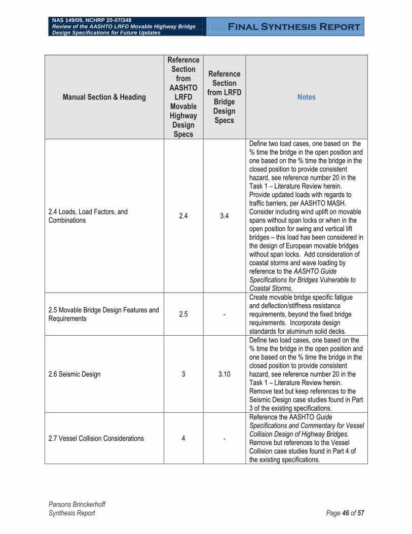
NAS 149/09, NCHRP 20-07/348 Review of the AASHTO LRFD Movable Highway Bridge Design Specifications for Future Updates
Final Synthesis Report
Parsons Brinckerhoff Synthesis Report Page 46 of 57
Manual Section & Heading
Reference Section
from AASHTO
LRFD Movable Highway Design Specs
Reference Section
from LRFD Bridge Design Specs
Notes
2.4 Loads, Load Factors, and Combinations
2.4 3.4
Define two load cases, one based on the % time the bridge in the open position and one based on the % time the bridge in the closed position to provide consistent hazard, see reference number 20 in the Task 1 – Literature Review herein. Provide updated loads with regards to traffic barriers, per AASHTO MASH. Consider including wind uplift on movable spans without span locks or when in the open position for swing and vertical lift bridges – this load has been considered in the design of European movable bridges without span locks. Add consideration of coastal storms and wave loading by reference to the AASHTO Guide Specifications for Bridges Vulnerable to Coastal Storms.
2.5 Movable Bridge Design Features and Requirements
2.5 -
Create movable bridge specific fatigue and deflection/stiffness resistance requirements, beyond the fixed bridge requirements. Incorporate design standards for aluminum solid decks.
2.6 Seismic Design 3 3.10
Define two load cases, one based on the % time the bridge in the open position and one based on the % time the bridge in the closed position to provide consistent hazard, see reference number 20 in the Task 1 – Literature Review herein. Remove text but keep references to the Seismic Design case studies found in Part 3 of the existing specifications.
2.7 Vessel Collision Considerations 4 -
Reference the AASHTO Guide Specifications and Commentary for Vessel Collision Design of Highway Bridges. Remove but references to the Vessel Collision case studies found in Part 4 of the existing specifications.

NAS 149/09, NCHRP 20-07/348 Review of the AASHTO LRFD Movable Highway Bridge Design Specifications for Future Updates
Final Synthesis Report
Parsons Brinckerhoff Synthesis Report Page 47 of 57
Manual Section & Heading
Reference Section
from AASHTO
LRFD Movable Highway Design Specs
Reference Section
from LRFD Bridge Design Specs
Notes
2.8 Vehicle Collision Considerations - - Draft a new section to address movable bridge specific issues for traffic barriers, including reference to AASHTO MASH.
3: Machinery Design 5, 6 - Combine Parts 5 and 6 of the existing specifications into one mechanical part, for clarity.
3.1 Scope 5.1, 6.1 - Combine the existing Sections 5.1 and 6.1, in order to consolidate the machinery design into a single part, for clarity.
3.2 Definitions 5.2, 6.2 - Combine the existing sections 5.2 and 6.2, in order to consolidate the machinery design into a single part, for clarity.
3.3 Notation 5.3, 6.3 - Combine the existing Sections 5.3 and 6.3, in order to consolidate the machinery design into a single part, for clarity.
3.4 Machinery Layout and Reliability - -
Draft new section to incorporate the reliability-based approach proposed in Task 3 herein. Specifically, the section will provide a numerical reliability goal for newly designed machinery systems, as well as a method for calculating the reliability of a proposed system. As an example, this section will aid the design engineer in determining if redundant/auxiliary/parallel components or sub-systems may be justified for a given design.
3.5 Mechanical Design Loads and Power Requirements
5 - No change
3.5.1 Sizing Prime Mover for Span Operation
5.4 - Clarify that starting torque load includes inertial load.
3.5.2 Holding Requirements 5.5 - No change
3.5.3 Sizing Brakes 5.6 - No change
3.5.4 Machinery Design Criteria 5.7 - Add reference to system reliability with regards to auxiliary drives.
3.5.5 Machinery Efficiencies and Losses 5.8 - No change

NAS 149/09, NCHRP 20-07/348 Review of the AASHTO LRFD Movable Highway Bridge Design Specifications for Future Updates
Final Synthesis Report
Parsons Brinckerhoff Synthesis Report Page 48 of 57
Manual Section & Heading
Reference Section
from AASHTO
LRFD Movable Highway Design Specs
Reference Section
from LRFD Bridge Design Specs
Notes
3.6 Resistance of Machinery Parts 6.6 -
Establish a procedure for applying structural load factors to be applied to mechanical components that support dead load and live load, such as lock bars, trunnions, tread plates, center bearings, wedges, etc.
3.6.1 Resistance at the Service Limit State
6.6.1 - No change
3.6.2 Resistance of Components in Bearing at the Service Limit State
6.6.2 - No change
3.6.3 Design for the Fatigue Limit State 6.6.3 - No change
3.6.4 Resistance of Open Spur Gearing Using Allowable Stresses
6.6.4 -
Revise AASHTO 1998 LRFD Movable Highway Bridge Design Specifications Section 6.6.4, per latest version of AGMA 2001-C95. This revision is proposed in order to bring the specifications to current standards.
3.6.5 Wire Rope Allowable Stress 6.6.5 - No change
3.7 Machinery Component Design 6.7 - No change
3.7.1 Requirements for Design with Static Stresses
6.7.2 - No change
3.7.2 General Requirements for Design with Fluctuating Stresses at the Fatigue Limit State
6.7.3 - No change
3.7.3 Shafts, Trunnions, Machine Elemements Subjected to Cyclic Stresses
6.7.4 - No change
3.7.4 Design of Open Spur Gearing 6.7.5 - No change
3.7.5 Enclosed Speed Reducers 6.7.6 - No change
3.7.6 Bearing Design 6.7.7 - No change
3.7.7 Fits and Finishes 6.7.8 - No change
3.7.8 Hubs, Collars, and Couplings 6.7.9 - No change
3.7.9 Keys and Keyways 6.7.10 - No change
3.7.10 Splines 6.7.11 - No change
3.7.11 Mechanical Shrink Fit/Frictional Assemblies
6.7.12 - No change
3.7.12 Motor and Machinery Brake Design
6.7.13 - No change

NAS 149/09, NCHRP 20-07/348 Review of the AASHTO LRFD Movable Highway Bridge Design Specifications for Future Updates
Final Synthesis Report
Parsons Brinckerhoff Synthesis Report Page 49 of 57
Manual Section & Heading
Reference Section
from AASHTO
LRFD Movable Highway Design Specs
Reference Section
from LRFD Bridge Design Specs
Notes
3.7.13 Machinery Support Members and Anchorage
6.7.14 - No change
3.7.14 Fasteners, Turned Bolts, and Nuts 6.7.15 -
Consider allowing dowels in lieu of turned bolts for connecting machinery to supports. This method is less labor intensive, therefore less expensive, and can provide an acceptable shear connection. Dowels are used in other industries, such as power plants and mills. The fit between fastener and hole for both turned bolts and dowels are very tight (typically less than 0.010 inches).
3.7.15 Miscellaneous Machinery Requirements
6.7.16 - No change
3.8 Bridge Type Specific Machinery Design
6.8 - No change
3.8.1 Bascule Spans 6.8.1 - No change
3.8.2 Swing Spans 6.8.2 - No change
3.8.3 Vertical Lift Spans 6.8.3 - No change
3.8.4 Uncommon Types of Movable Spans
- -
Draft new section to briefly address other types of movable spans, including floating and ferry transfer spans as they are also typically designed following these specifications..
3.9 Emergency Drives 6.9 - No change
3.10 Suggested Machinery Alignment Tolerances
- -
Draft a new section providing suggested machinery alignment requirements. Machinery alignment is a significant issue with regards to field labor costs and life of the machinery and is not current covered in the specification.
3.11 Lubrication 6.10 - No change
3.12 Water Drainage - -
Draft new section addressing the importance of drainage, both with regards to locating machinery away from storm water flows and detailing machinery to prevent water pooling within the components.

NAS 149/09, NCHRP 20-07/348 Review of the AASHTO LRFD Movable Highway Bridge Design Specifications for Future Updates
Final Synthesis Report
Parsons Brinckerhoff Synthesis Report Page 50 of 57
Manual Section & Heading
Reference Section
from AASHTO
LRFD Movable Highway Design Specs
Reference Section
from LRFD Bridge Design Specs
Notes
4: Hydraulic Machinery Design
7 - n/a
4.1 General Requirements 7.1 - No change
4.2 Definitions 7.2 - No change
4.3 Notation 7.3 - No change
4.4 Hydraulic Circuit and Reliability - -
Draft new section to incorporate the reliability-based approach proposed in Task 3 herein. Specifically, the section will provide a numerical reliability goal for newly designed hydraulic systems, as well as a method for calculating the reliability of a proposed system. As an example, this section will aid the design engineer in determining if redundant/auxiliary/parallel components or sub-systems may be justified for a given design.
4.5 Design Loading Criteria 7.4 - No change
4.6 Components 7.5 - No change
4.7 General Design Provisions 7.6 - No change
4.8 Detailing of Hydraulic Systems 7.7 - No change
4.9 Fabrication and Construction 7.8 - No change
4.10 Materials 7.9 - No change
5: Electrical Design 8 - No change
5.1 General Design Requirements 8.1 - No change
5.2 Definitions 8.2 - No change
5.3 Electrical Systems and Reliability - -
Draft new section to incorporate the reliability-based approach proposed in Task 3 herein. Specifically, the section will provide a numerical reliability goal for newly designed electrical systems, as well as a method for calculating the reliability of a proposed system. As an example, this section will aid the design engineer in determining if redundant/auxiliary/parallel components or sub-systems may be justified for a given design.
5.3 Electrical Supply and Power Distribution
8.3 - No change
5.4 Electrical Control Systems 8.4 - Add discussion regarding remote control

NAS 149/09, NCHRP 20-07/348 Review of the AASHTO LRFD Movable Highway Bridge Design Specifications for Future Updates
Final Synthesis Report
Parsons Brinckerhoff Synthesis Report Page 51 of 57
Manual Section & Heading
Reference Section
from AASHTO
LRFD Movable Highway Design Specs
Reference Section
from LRFD Bridge Design Specs
Notes
5.5 Electric Motors 8.5 - No change
5.6 Electric Motor Controls 8.6 -
Add discussion on the various types of motor drives available e.g. AC Flux Vector Variable Frequency, DC SCR, Variable Voltage, etc. that are now commonly used for movable bridges.
5.7 Electrically Operated Brakes 8.7 - No change
5.8 Control Cabinets 8.8 - No change
5.9 Electrical Conductors 8.9 - No change
5.10 Conduits, Wireways, Boxes, and Cabinets
8.10 - No change
5.11 Service Lights and Receptacles 8.11 - No change
5.12 Grounding 8.12 - No change
5.13 Lightning Protection 8.13 - No change
5.14 Spare Parts 8.14 - No change
References
Appendix A3-
Seismic, A4-Vessel Collision
-
Add recent seismic analysis projects of movable bridges: 145th Street Swing Bridge in NYC, Macombs Dam Swing Bridge in NYC, Ben Sawyer Swing Bridge in South Carolina
Index - - Create an index
Appendix A - SI Versions of Equations, Tables, and Figures
Appendix A - No change

NAS 149/09, NCHRP 20-07/348 Review of the AASHTO LRFD Movable Highway Bridge Design Specifications for Future Updates
Final Synthesis Report
Parsons Brinckerhoff Synthesis Report Page 52 of 57
TASK 6 – PRESENT TO THE AASHTO HSCOBS TECHNICAL COMMITTEE T-8 MOVABLE BRIDGES
The 2014 annual meeting for the AASHTO Highway Subcommittee of Bridges and Structures (HSCOBS), including a session of the T-8 Movable Bridges technical committee was held on April 23, 2014 in Columbus, Ohio. The Parsons Brinckerhoff team presented the progress of project NAS 149/09 – NCHRP 20-07/348 Review of the AASHTO LRFD Movable Highway Bridge Design Specifications for Future Updates.
A second presentation to the AASHTO T-8 Subcommittee was given on April 19, 2015 at the Annual AASHTO Subcommittee on Bridges and Structures (SCOBS) April 19, 2015, in Saratoga Springs, New York.
The presentation slides are available for download at: bridges.transportation.org/Pages/AnnualMeetingPresentations.aspx

NAS 149/09, NCHRP 20-07/348 Review of the AASHTO LRFD Movable Highway Bridge Design Specifications for Future Updates
Final Synthesis Report
Parsons Brinckerhoff Synthesis Report Page 53 of 57
TASK 7 – DEVELOP RESEARCH PROBLEM STATEMENT
The below proposed research problem statement is submitted to the NCHRP technical panel for review and
comment. The proposed research problem statement includes sections discussing the background,
objectives, and tasks recommended for a future project.
BACKGROUND Of the nearly 600,000 bridges listed in the Federal Highway Administration‟s (FHWA) National Bridge Inventory, close to 1,000 bridges are movable bridges. The design, installation and maintenance of movable bridge structural, mechanical and electrical components constitute significant challenges and costs for movable bridge owners. The primary design guide for movable bridge design and construction currently is the AASHTO LRFD Movable Highway Bridge Design Specifications, Second Edition, published in 2007 with yearly Interim Revisions from 2008 to 2012. Based on the input from movable bridge industry, there is a desire to further update the current specifications to develop and implement a reliability-based design methodology and to reflect advances in electrical drives and controls, mechanical systems, and traffic/marine safety systems. Towards this goal, an outline identifying proposed revisions of the re-titled AASHTO Movable Bridge Design Specifications (Specifications), was prepared for project NAS 149/09 – NCHRP 20-07/348 Review of the AASHTO LRFD Movable Bridge Design Specifications for Future Updates, completed in 2015. The outline provides a foundation for the further research scoped below. The proposed title would no longer include the term LRFD and the reason for this is based on the fact that for movable machinery, power and controls, the proposed Specifications will adopt a reliability-based approach, which is consistent with how mechanical and electrical systems are designed. This proposed change is also consistent with industry comments received during the program.
OBJECTIVE The objectives of this research are to:
(1) Propose revisions to the Specifications. The revisions should be prepared recognizing the latest
developments in movable bridge design and rehabilitation. Additionally, the proposed revisions
should be consistent with adopted AASHTO specifications and manuals.
(2) Propose recommendations for future research needs.

NAS 149/09, NCHRP 20-07/348 Review of the AASHTO LRFD Movable Highway Bridge Design Specifications for Future Updates
Final Synthesis Report
Parsons Brinckerhoff Synthesis Report Page 54 of 57
TASKS PHASE I - Planning Task 1. Review the Synthesis Report prepared for project NAS 149/09 – NCHRP 20-07/348 Review of the AASHTO LRFD Movable Bridge Design Specifications for Future Updates. Prepare comments. Task 2. Revise, if necessary, the proposed outline identifying proposed revisions of the Specifications. Task 3. Recommend and quantify a minimum level of reliability to be used for the design of movable bridge mechanical, electrical, and traffic/marine safety systems. Consider if the recommended level of reliability is site specific or uniform nationwide. Consider reliability both with regards to 1) the ability for a movable bridge to remain operable and 2) the structural reliability and load factors of mechanical components – such as span locks, trunnions, tread plates, center bearings, wedges, end lifts, and hydraulic machinery.. Task 4. Prepare Interim Report No. 1 that documents Tasks 1 through 3 and provides an updated work plan for the remainder of the project. PHASE I – Manual Update Task 5. Execute the approved work plan to revise the Specifications. Task 6. Describe the potential impact of the proposed revisions to the Specifications Task 7. Prepare a Draft Synthesis Report that documents Tasks 5 through 6 of Phase II. PHASE I – Final Products Task 8. Update proposed modifications to the Specifications after consideration of review comments and prepare ballot items for AASHTO Highway Subcommittee on Bridges and Structures consideration. Task 9. Prepare a final Synthesis Report that documents the entire research effort.

NAS 149/09, NCHRP 20-07/348 Review of the AASHTO LRFD Movable Highway Bridge Design Specifications for Future Updates
Final Synthesis Report
Parsons Brinckerhoff Synthesis Report Page 55 of 57
TASK 8 – SYNTHESIS REPORT
The Synthesis Report herein describes the entire research effort and was prepared under Task 8.

NCRRP Project 20-07/Task 348
Review of the AASHTO LRFD Movable Highway Bridge Design Specifications for future updates
56
PROJECT SCHEDULE:
Milestones/Deliverable
2013 2014 2015
TASK Jun
e
July
Au
gust
Sep
tem
ber
Oct
ob
er
No
vem
ber
Dec
emb
er
Jan
uar
y
Feb
ruar
y
Mar
ch
Ap
ril
May
Jun
e
July
Au
gust
Sep
tem
ber
Oct
ob
er
No
vem
ber
Dec
emb
er
Jan
uar
y
Feb
ruar
y
Mar
ch
Ap
ril
May
Jun
e
Task 1: Review relevant literature and practices
Task 2: Synthesize the various types of 1) mechanical systems and 2) electrical drives and controls
Task 3: Discuss the application of reliability-based design to mechanical, electrical, and traffic/marine safety systems for movable bridges
Task 4: Outline proposed areas of AASHTO LRFD Movable Bridge Design Specifications for future update
Task 5: Revise the outline per NCHRP project panel comments
Task 6: Present to the AASHTO HSCOBS Technical Committee T-8 Movable Bridges; Revise outline
Task 7: Develop research problem statement
Task 8: Synthesis report NCHRP Review

NAS 148/08, NCHRP 20-07/348 Review of the AASHTO LRFD Movable Highway Bridge Design Specifications for Future Updates
Report for Tasks 1 to 4
57
MEETINGS, DELIVERABLES, AND SCHEDULE MILESTONES:
Meetings
- No further meetings are scheduled.
Deliverables
- No further deliverables are scheduled.
- May 22, 2015: Submit Final Synthesis Report