final report space station auxiliary by j.m ... acceptance testdata obtained isincludedintheappendix...
TRANSCRIPT

FINAL REPORT
SPACE STATION AUXILIARY
THRUST CHAMBER TECHNOLOGY
BY
J. M. SENNEFF, PROGRAM MANAGER
BELL AEROSPACE TEXTRON
BUFFALO, NEW YORK 14240
FEBRUARY 1987
CONTRACT NAS 3-24883
BELL REPORT NO. 8911-950003
PREPARED FOR
NATIONAL AERONAUTICS AND SPACE ADMINISTRATION
https://ntrs.nasa.gov/search.jsp?R=19890002432 2018-05-21T17:21:17+00:00Z


CONTENTS
Section
FOREWORD..................................................
ABSTRACT ..................................................
SUMMARY...................................................
INTRODUCTION..............................................
APPENDIXA .................................................
Page
i
1
2
3
21
Figure
1
2
3
4
5
6
7
8
9
1011
12
13
ILLUSTRATIONS
Model 8911 Thrust Chamber ....................................
Model 8911 Thruster ...........................................
Model 8911 Regeneratively Cooled Nozzle ........................
Model 8911 Fuel Injector .......................................Nozzle Liner with Clamshell Nozzle Shroud .......................
Model 8911 Thrust Chamber Test Assembly .......................
Altitude Test Complex .........................................
Specific Impulse versus Mixture Ratio ............................
200 MillisecondPulses,Test No. A2-4421 .........................
120 MillisecondPulses,Test No. A2-4422 .........................60 MillisecondPulses,Test No. A2-4423 ..........................
40 MillisecondPulses,Test No. A2-4424 ..........................
Mean Impulse Bit versus Pulsewidth ..............................
Page
4
56
6
9
10I0
13
15
16
17
18
19
TABLE
Number
Drawing List .................................................Thruster Design Parameters ....................................Chamber Temperature Data at 29.4 Seconds ......................
Page
57
13


Foreword
Bell Aerospace Textron submits thisFinal Report as part of the Space Station
Auxiliary Thrust Chamber Technology Program, Contract NAS 3-24883.
The work was conducted under the cognizance of Mr. G. Paul Richter of NASA
Lewis Research Center who was the Contract Project Manager. Bell personnel
include: John M. Senneff, Program Manager; Arthur M. Gorbaty, Design
Leader; and Edgar R. Vollaro, Test Director.
Abstract
A program to design,fabricate and test a 50 Ibf (222 N) thruster was
undertaken (Contract NAS 3-24656) to demonstrate the applicabilityof the
"reverse flow" concept as an item of auxiliarypropulsion for the Space
Station. The thruster was to operate at a mixture ratio (O/F) of 4, be capable
of operating for 2 millionibf-seconds (8.896million N-seconds) impulse with a
chamber pressure of 75 psia (52 N/era 2)and a nozzle area ratio of 40. A
successful demonstration of the (O/F) of 4 thruster,was followed by the design
objective of operating at an (O/F) of 8. The demonstration of thisthruster
resulted in the order of an additional(O/F) of 8 thrustchamber under the
present NAS 3-24883 contract. This report isto document the effort to
fabricate and testthe second (O/F) of 8 thruster on contract NAS 3-24883.


SUMMARY
A program to evaluate a gaseous-hydrogen and gaseous-oxygen-fueled reverse-
flow thruster for the Spac_ Station Auxiliary Propulsion System was initiallyundertaken
with the design, fabrication and testing of a 50 Ibf (222N) thrust rocket engine under
contract NAS 3-24656. The thruster was designed to operate at 75 psia (52 N/Cm 2)
chamber pressure, and a mixture ratio (O/F) of 4 with a 40 to 1 nozzle area ratio. The
objective was to demonstrate a duration capability of 2 million Ibf-second (8.896 million
N-seconds) total impulse.
The original program included tasks for preliminary and detailed design,
fabrication, acceptance testing, duration testing and reporting. Four additional tasks
were added to the program when other NASA studies indicated a requirement to operate
the thrusters at a mixture ratio of 8 instead of the initially selected mixture ratio of 4.
This program was completed and has been reported in NASA CR-179552.
The current program was to duplicate the thrust chamber designed in contract
NAS 3-24656 at an (O/F) of 8. The effort included the fabrication and acceptance
testing of this thrust chamber. Also included was a task to update the drawings of the
original contract which were not completed in the rush to test and evaluate feasible
operation at the higher mixture ratio.
The acceptance test of this second thrust chamber was completed and the test
results are included in this report. New to this test program were pulse tests (200
milliseconds to 40 milliseconds long), conducted to examine the rapidity of pulses capable
with present valve and ignition components. The results of all tests are included in this
report.


INTRODUCTION
The manned Space Station willrequire an Auxiliary Propulsion System (APS)
for attitude control,orbit positioning,and docking maneuvers. The selection of an
optimum APS for the Space Station isa complicated issue,considering propellant
selection,thrust size,and operating conditions. The reverse flow thruster concept has
been considered to be a viable candidate for use with the gaseous hydrogen, gaseous
oxygen propellant system and a 50 Ibf (222N) thruster was demonstrated during a
recently completed NAS 3-24656 contract (NASA CR-179552).
Design detailsand the testingdata to achieve both the r=4 and r=8 thruster
designs are reported in NASA CR179552 while additionaltesting was originallysuggested
for the present NAS3-24883 contract. Although additionaltesting was suggested, only
those tasks which included the fabricationand acceptance testingof the new thruster
were included. This effortdid include the update of drawings which were not completed
during the rush to demonstrate the r=8 thruster during the NAS 3-24656 contract.
The three tasks agreed on were:
Task I - Thrust Chamber Fabrication
Task II - Proof Testing and Delivery
Task V - Reports
Since thisprogram was essentiallyone to duplicate the originalthruster,the
techniques originallyused in fabricationand test were duplicated for the second unit.
The acceptance test data obtained isincluded in the appendix of thisreport.


The 50 Ibf Thruster Design
The design of this thruster has been described in detail in NASA CR 179552.
Some of that description _,asbeen included in this report to add clarity to the tasks
reported.
The reverse flow thruster designed for this application is shown in Figure 1.
The basic components of this thruster are the spherical chamber (combustor), the vortex
oxidizer swirl cup, the nozzle (including the regen-cooled throat and the fuel inlet) and
the nozzle extension. Other components include the spark plug igniters (the exciter and
lead are now shown) with auxiliary oxidizer cooling and the propellant valves.
Photographs of the test hardware in Figure 2 show both the components and the thruster
assembly. The drawing listfor the r=8 thruster is included as Table I.
FuelInlet
Igniter Coolant
Fuel Valve
Oxidizer Valve
Ig
Ox Inlet
_zzle Extension
Cooled Liner
4.39InjectorReverse Flow t ..... -- - RefChamber
Oxidizer Swirl CuInjector
Figure 1.
15.63 Ref
Model 8911 Thrust Chamber
!


OF POOR "_ "' "QU_-..-_; ¥
(Exploded View)
(Assembled)
Figure 2. Model 8911 Thruster
[ABLE 1. I)RAWlN(; LIST
8911-470021
8911-470002
8911-470003
8911-470024
8911-470005
8911-470006
8911-470027
8911-470028
8911-470009
8911-470030
8911-470011
8911-470012
12350
FHE 297-1
45582
Engine Assembly 50 Lbf -02/'H 2 M.R. = 8
Nozzle Extension
Coolant/Augmentation Tube Assemblies
Fuel Manifold Assembly
Split Shroud
Nozzle Liner Assembly
Oxidizer Injector Subassembly
Oxidizer Inlet Subassembly
Chamber Subassembly
Chamber Assembly
Igniter Boss Assembly
Adapter, Chamber Pressure (Propellant Valves)
Wright Components Inc.
Igniter
Simmonds Exciter


The fuel inlet and nozzle design is shown in Figure 3. The propellant enters
the nozzle at midsection and is routed aft to enter both the divergent nozzle film coolant
manifold and the nozzle regeneratively-eooled passages. H 2 flows through these cooling
passages and out the fuel injeetion orifiees, as indieated in Figure 3 and Figure 4. The
fuel then passes openly along the spherical ehamber wall until turned into the oxidizer
stream at the head of the chamber.
Assy
-- Ring
Injector
Shroud
I (6061T6AI
_-Nozzle CoolinlSlots
Fuel Cooled \Nozzle Liner \
(Amzirc)
Piston Ring Seals
/Metal "O" Ring
Figure 3. Model 8911
Regeneratively Cooled
Nozzle
Fuel Manifold-(Cres 304L)
A
' .%
24 Fuel Injection Slots
Figure 4. Model 8911 Fuel Injector
6

The oxidizer flows into the chamber from the valve to the inlet of the vortex
cup, through a distribution baffle, and then enters the vortex cup through the swirl
orifices and the centerflow orifice. A small amount of oxidizer is drawn from the vortex
cup inlet as a spark plug eoolant and auxiliary ignition propellant (1/2 pereent each
igniter).
The construction materials used for this thruster reflect the objective of
incorporating low-cost readily-available materials throughout. The thruster has a Type
304 stainless steel oxidizer injector and nozzle holder with Hastelloy X combustion
chamber. The throat section (nozzle liner) is fabricated from Amzirc copper and the
nozzle shroud (coolant passage eloseout) is a wrap-around two-piece Type 6061 aluminum
part. The thruster nozzle extension was fabricated from Hastelloy X.
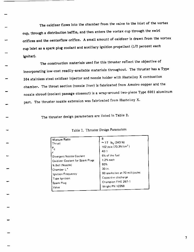
The thruster design parameters are listed in Table 2.
Table 2. Thruster Design Parameters
Mixture Ratio
Thrust
Pc
E
Divergent Nozzle Coolant
Oxidizer Coolant for Spark Plugs
% Bell (Nozzle)
Chamber L*
Ignition Frequency
Type Ignition
Spark Plug
Valve
8
_77 Ibf(343N)
102 psia (70.3N/cm 2 )
40:1
6% of the fuel
1.2% each
8O%
30 in.
60 sparks/sec at 70 millijoules
Capacitive discharge
Champion FHE 297-1
Wright PN 12350


Fabrication
One of the benefits of the reverse flow combustor concept is the simple
construction techniques used in its fabrication, the uncooled Hastelloy X chamber and
related parts, which were the baseline for this program, introduced the temperature
limitations related to this material. The oxidizer vortex cup and inlet, and various add-
ons such as the spark plug attachments, chamber pressure ports and coolant lines were all
fabricated from type 304L stainless steel as was the nozzle manifold assembly.
The most complex portion of this design was the nozzle liner assembly where
all the coolant passages were Electric Discharge Machined (EDM'd). The design feature
of holding the nozzle near the fuel injection orifices necessitates a holding flange at this
location. This holding flange allowed longitudinal thermal expansion of the liner as with
the sliding nozzle seal. The complexity existed in the EDM fuel injection slots which
required a compound slot profile to transition from the coolant passage end at the
chamber periphery. These injection slots were neatly fabricated by rotating the EDM
electrode from the flat fuel injection orifices. This copper nozzle is shown in Figure 5,
along with the surrounding aluminum closeout. The coolant passages can be seen along
the nozzle axis while the fuel injection orifices are at the top of the unit. This
construction technique was selected for this technology demonstration to facilitate both
design and fabrication. A flight unit would be modified to include an electrodeposited
closeout for the coolant passages, in turn allowing a much less complex configuration of
the fuel injection orifices.
The final thruster component was the Hastelloy X nozzle extension attached at
an area ratio of 10. Hastelloy was selected for the extension so that the possibility of


Figure 5. Nozzle Liner with (lamshell Nozzle Shroud
eliminating the nozzle dump coolant could be explored. Due to the press of other
objectives, this possibility was not investigated during the program.
The mixture ratio 8 hardware was similar to the original hardware with the
only fabrication change being a Hastelloy X chamber incorporated to allow slightly
higher chamber temperatures at the higher mixture ratio. The chamber was fabricated
on a normal contour lathe and welding the stainless steel 304L chamber accessories
presented no problems. The thrust chamber assembly, ready to be mounted in the test
cell, is shown in Figure 6.
Test Ob_ect!ves
The objective of the test program has been outlined in Bell Operational Test
Plan, No. 8911-947002, with the test sequence listed in Appendix A of this report.
ORIGINAL PAGE
BLACK AND WHITE PHOTOGR'APN9


Figure 6. Model 8911 Thrust Chamber Test Assembly
Test Cell and Operation
All fire-testingof the Space Station Auxiliary Thruster was conducted in the
Bell Altitude FacilityA-2. The test cellused has a nominal altitude capabilityof
120,000 feet (36576 M) with a duration capabilityfar in excess of I000 seconds. The Bell
altitudefacilityisoperated by a dedicated steam generation system tied in with the
factory power plant,providing low-cost operations of almost unlimited duration. The
general arrangement of the facilityisshown in Figure 7. M,
I Multi-
Stage
EjectorSystem
Figure 7. Altitude Test Complex
J
Isolation Valves Sea Level Valve Open for Sea Level Test
ORIGINAL PAGE
BLACK AND WHITE PHOTOGRAPH
10


Operation of any test cellisaccomplished by directing steam into one of the
three ejectors,each having itsown capacity limit. The test cellclosure valve isopened
to the ejector exhaust system, drawing the celldown to the requisitealtitude.
Operation of the thruster is accomplished by a timer panel. The start and
shutdown sequence of events to the igniter and valve systems are preplanned and operate
in an automatic sequence. For these tests, the fuel valve was sequenced to open one
millisecond ahead of the oxidizer valve, although no confirmation measurements were
attempted to ascertain the propellant chamber entry sequence. Pulse tests were
conducted with equal on and off times.
Ignitionwas accomplished with the use of an exciter,having an approximate
frequency of 60 sparks per second, operating a spark plug installedin the combustor
wall. Examination of the start traces showed positive and immediate startswith the
firstspark after positiveoxidizer pressure was identified.
Instrumentation
Normal performance measurement parameters, includingthrust,chamber
pressure and propellant flow rates,were measured for alltests. Flow rates were
measured using temperatures and sonic orifices. Cell instrumentation includes an in-line
load cellthrust measuring arrangement where the thrustchamber is mounted vertically
and fired in a downward direction. Three stabilizingwebs were used on the chamber
mount so that thrust alignment was maintained.
Temperatures were measured with thermocouples placed at various positions
on the thruster. Since there has been very littleprecedent for failurecriteriafor this
II

type of thrust chamber, thermocouples were placed at various positions on the thrust
chamber to establish criteria for the formulation of a more complete heat monitoring
arrangement. Thermocouples were placed on the nozzle extension, at the nozzle flange,
on one of the lands in the copper nozzle liner, in a coolant passage and on the combustion
chamber at a variety of positions. Thermocouple locations are shown in the appendix A
of this report.
Test Results and Discussions
The acceptance test series was predefined and consisted of 4 sets of tests.
Test sets were designed to examine mixture ratio, chamber pressure, heat rejection
(measured hardware temperature) and pulse performance. The tests were performed as
predefined with the exception that an added pulse set was completed. The test schedule
is noted in Figure A-I of the Appendix. The test data is included in this Appendix.
The measured specific impulse is shown graphically in Figure 8. It was noted
that the recorded specific impulse at a mixture ratio of 8 was approximately the same as
for the original thruster tested, thruster No. I (contract NAS 3-24656), however, the new
thruster, thruster No. 2, appears to have somewhat lower performance at the more fuel
rich mixture ratios.
The thrust chamber thermocouples were also examined for comparison to
thruster No. I. The mixture ratio =8 data is noted in Table 3 where it is compared to
similar data for the thruster No. i.
While the average of this data is close for the two thrusters, the
circumferential variation of the temperatures issomewhat larger on thruster No. 2.
12


Additional testing, which might be required to explain this difference, is beyond the
scope of the contract.
360 ,-
350 -
340 -
Specific Impulse,
Isp (Ibf/Ibm/sec)
330 -
320 -
310 -
High Pc
Low pc_
I I I I 1
4.0 5.0 6.0 7.0 8.0
Mixture Ratio (O/F)
Figure 8. Specific Impulse Vs Mixture Ratio
Table 3. Chamber Temperature Data at 29.4 Seconds.
Mixture
Test No. Ratio (O/F)
4420 8.104
Thruster No. 2
ThermocoupleNo.
10
11
20A
21A
Average
Temperatureo F Test No.
Thruster No. 1
Mixture ThermocoupleRatio (O/F) No,
Temperature-F
1575,8
1909.5
1519.8
1773.8
1694.7
4379 7.926 10
11
20A
21A
Average
1770.2
1492.9
1731.8
1707.8
1675,7
13


Pulse Testing
Pulse tests were conducted with thruster No. 2 by the simple expedient of
setting on/off times into the run panel and operating for the prescribed 15 pulses. The
ignitor system was held in the on position, due to the expediency of wiring the ignition
system independently of the timing panel.
The concern for pulse operation was that the combined delays of the propellant
valves and the ignition system would be too great to produce 40 millisecond pulses. The
result could have been external ignition with some detrimental effects. The 60
millisecond pulses were considered minimum, which the test results confirmed. The 40
millisecond pulses did not ignite until after the valve had closed in 5 of the 15 pulses
attempted. The propellant valve timing was originally reported as 30 milliseconds as
normal open and close time. The actual time turned out to be closer to 30 milliseconds
opening and 15 milliseconds closing, meaning that the on/off time would limit a pulse
fluid flowtime to some 15 to 20 milliseconds shorter than the pulse electrical time used.
This condition was not expected to materially affect the longer duration pulses
(greater than 60 milliseconds). Pulse data for each of the series conducted isshown in
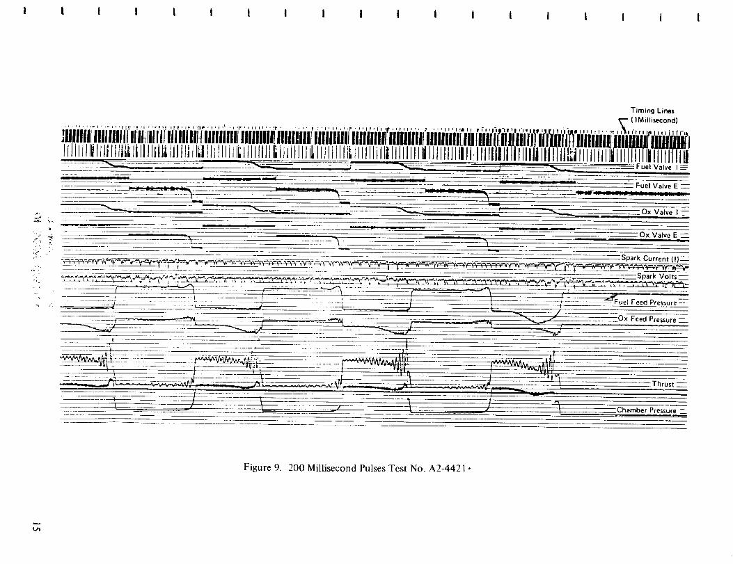
Figures 9, I0, II and 12.
The shorter pulse time effect of ignition and valve timing is shown in the
drastic differences between the 40 millisecond pulses (Figure 12). During these pulses,
the valve in many cases shut off before any ignition occurred, although ignition occurred
in every pulse. This late ignition resulted from the delayed exciter timing when the
capacitive discharge systems were in phase with a spark rate of approximately 45 sparks
per second or 22 milliseconds between sparks. The 22 millisecond ignition delay is
approximately what isseen on the 40 millisecond pulses where the ignition spike occurred
14

i i i I i l I I I i i i i i i i I i i
Timing Lines
......... _"-,",_-_.;., ,'-ft.* ,:,,,_,_-.t,tO .,._,,,,t,,._ ..... t :',.,,_,.o , . .... --_ (1Millisecond)
]!i11111Ilillililtlilliliilltlilllllllttlllliill_M__M_._j_i_i_j_i.i_iii_ii_iiii_iH'_i_'_ii_I_i_Ii_'_jiii_j_|_i__i_j_l_l_i_iL=j_iLi_i_;I_i_i_I;_ki_L_i_i_;L_i__j___ IIIIIIIiIIIiilllllill IIIIIIIIIII1_1-il
..ii,__ _Fuel Valve I __
.... -'"_- = = "'-'--_ __ _uel Valve E --
........ _ Z_.__ _ _ _ --'-Ox Valve I
...... . _ Ox Valve E ...._ _ ,-,
-_'_'_r%_/_r _ _ _*=_¢"_ _,--_-V'_*_/___%' Spark Current (11_-
Thrust --
Chamber Pressure --
Figure 9. 200 Millisecond Pulses Test No. A2-4421 •


* i t t i I I t i, il i I f i i I i I i
Timing Lines
. n iI1!_ illlf IP P f f 1 ' P I 'l.e ' ' I ' ! ' ! 1=" I? I I t t I t ,r t t f_ n f_ I ' IITpItlrl u tit '_' I ! tl_ I t I I I t I t i_ I I I I I i i r ._ i i i t , , i , .T t i [ i u I t i iql l| i | 1st '*, t * _-..-.-., ( 1 _V_ second)
lllll!llI[l!llllllll!lllllfll/III!IIIIII IIIIIIIII{III!IIIlIIilllllillrlililIIIIIilllilill{MlillliliililiHiifliliHlllfill[iflM'fll'liiiiiii'i: ii'li]'l 'liiiYJ,' i'h:,___i__i_____ II Illllilllitij IIIIIIliillllllllillllltltlillllll Ililllllllllllllllill'Jtlll'l'li]'ijUiii'
-- -- -- -_--- -- __ _ -- -- --- --Fuel Valve I
Fuel Valve E
- _ _ __o,(v,,ve,
Ox Valve E
Spark Current (t)
, - ..... --___ ark Volts--
;::;_z __. -__L__ = _.. -zc ¢--- F ' "--__4- -_L_- 2 ....... _- . l _-- -_;--_ ..... I -_-_ _1 [ uel Feed Pressure -
.... ;,,- -_:---;_ .- L -- P 2:- k _- - L- j . W .crib- L ./ -
............................ "" 2"-- -----_-_'_t _, ,-_ z O x Feed Pressure "
=* _ . t ,j
"''I I : 1 I z • ;I I t ._ j yut,_ /
_ I ,I _ ._ _ _ _ I "i4_V, Thrust
_ _' J_ _ _ _Chamber Pressure:---___.__
Figure 10. 120 Millisecond Pulses, Test No.A2-4422.
o_


i I t I t I ! I | i I t I I I I i i
Timing Lines
, I r "r :1 , ! I_ _(1MiltisecOnd)
+ lli'iili'iilI'lll,..........ii'i,",",'..........'.....i,,,,,,,,,;,+''''''''" '..... iii+,'l,'........ IP II il;ii'll ;II; Illllll lllllll,IIIIIIPI,! IPIIIIIIIII'III!,!,'IIIIIIIII III,',I'I ,,'IPI, II','llii'liiiilliiii'llii'iilili' ' ' ""'"'"'"_' Fuel Valve IF
Fuel Valve E--
__=,,+ _ *-------__ _ _
_Ox Valve E--
_.._.,.._.-._+,_,__r'_ _--,n_v _ ..... _ -",park Volts -
_" _ Fuel Feed Pressure"_-----_Z-
___ _ ; __,._ Ox Feed Pressu e_
.... Thrust :
Chamber Pressure -
===.
O0wt_0
OZO__r-
,O'13E_
r.- rrt
-.4....-<U3
Figure i 1. 60 Millisecond Pulses, Test No. A2-4423.


"tTEITt,-_V"ON_SO_L'SaSlndpuo3os.ql!lN017
b.
t_J
,z:D.
-J
5
>-k-
(3'
0
0
aJnssaJd JaqtueqD L
- zsnJq.L
i I
_ asnssaJ d P_a d x 0 • /_
"SZl°A _lJeas , --- ------ • | tl , , ,
3 a^leA xo
-- I a^leA xo _ - "" _ _" _ _ -- _ " _ _ _" _ i
__3aaleAland! -; . , , =_- _ ::_ __ ' . _ "' _ _ ! " __ __ ' " " .: .. :__ _ L . --_ i :_ ' ,,, ' ' :
i - , i , i ii 1_a^leA lan:l =-'- ,-........
IIMllilIiltlIIlIIIIIJIlMI:IIIIMIIlI]IiilII tllllllllltllllllll tllillll I!lllflllllillllllllitllllllllltlllllllll llllllflll t!11111111tt!1111t]!tlI_ll]]llllglllI!!1t, ,;o.,_,.l,,.,,,,-,:_,,..........,,,,,,,,,,,,,.,,,,,.,,,,.,_.,,,..,,,.,.,,,,,,,,.,,,.............,,,,,,..............,,,,.........,.........,,,........,.... ,,,,,,,,,,,,,,,,,,,,,,.
sau! 1 6u!uu!l
' I ) I t I t I I I I t I t ! I I 1 I


during shutdown. The best pulses resulted, with immediate ignition, when the ignitor
fired as the propellants entered the chamber. A more rapid ignitor system is needed if
the 40 millisecond pulse is required.
The pulse data are ineluded in the Appendix. These data have been
summarized for total impulse for eaeh pulse with mean, minimum and maximum
summated. The mean value for the impulse bit is shown graphieally in Figure 13.
13
12
11
10
9
8
Mean Impulse Bit 7
(Ibf sec) (per pulse)6
5
4 _
3
2
1
m
B
m
B
n
D
I I I i I I I i i i0.02 0.04 0.06 0.08 0.10 0.12 0.14 0.16 0.18 0.20
Pulse Width (Seconds)
Figure 13. Mean Impulse Bit Vs Pulsewidth
19


Conclusions
An 8911-470021-I thruster assembly was fabricated and completed the defined
acceptance tests. This thruster demonstrated the capabilityto operate over an
extremely wide range of operating conditions similarto the previously fabricated
thruster assembly. Some differences were noted inperformance between the original
and new thruster,however, the differences are not large enough to be considered to be
detrimental to operation.
Pulse tests were alsoconducted on thisthruster assembly for the firsttime
with thistype of reverse flow thruster. The resultswere gratifying in that short duration
firings(60 milliseconds)produced repetitivepulses and that even shorter pulses are
practicalwith a more rapid spark exciter. This thrustchamber concept (reverse flow)
has again shown itsadaptabilityto the Space Station Mission.
2O

Appendix A
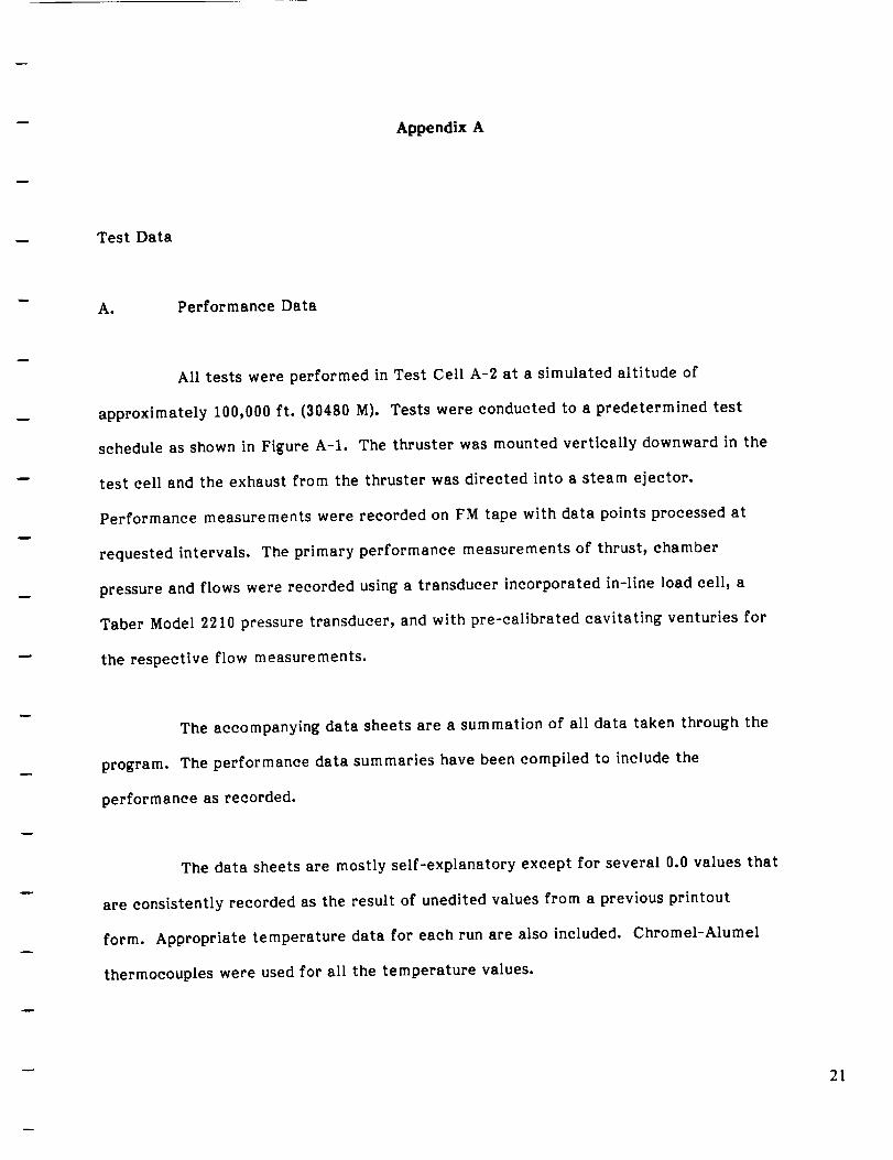
Test Data
A. Performance Data
All tests were performed in Test Cell A-2 at a simulated altitude of
approximately 100,000 ft.(30480 M). Tests were conducted to a predetermined test
schedule as shown in Figure A-I. The thruster was mounted verticallydownward in the
test celland the exhaust from the thruster was directed intoa steam ejector.
Performance measurements were recorded on FM tape with data points processed at
requested intervals. The primary performance measurements of thrust,chamber
pressure and flows were recorded using a transducer incorporated in-lineload cell,a
Taber Model 2210 pressure transducer, and with pre-calibrated cavitating venturies for
the respective flow measurements.
The accompanying data sheets are a summation of alldata taken through the
program. The performance data summaries have been compiled to include the
performance as recorded.
The data sheets are mostly self-explanatory except for several 0.0 values that
are consistentlyrecorded as the resultof unedited values from a previous printout
form. Appropriate temperature data for each run are also included. Chromel-Alumel
thermocouples were used for all the temperature values.
21


w
B. Pulse Test Data
ACCEPTANCE TESTS
A. Mixture Ratio Series
Test Pc r(psla) (O/F)
1 102 4.0
2 102 6.0
3 102 8.0
Duration
(sac)
5
5
5
B. Chamber Pressure Series
Test Pc r Duration(psia) (O/F) (sec)
1 102 8.0 5
2 75 8.0 5
3 125 8.0 5
C. Heat Rejection Series
Test Pc r
(psia) (O/F)
102 4.0
102 6.0
102 8.0
Duration
(sec)
3o
3o
3o
D. Pulse Series
TastNo. Pc r Pulse Dura-
Pulses (psia) (O/F) tion (sac)
15 102 8.0 0.200
15 102 8.0 0.120
15 102 8.0 0.060
15 102 8.0 0.040
Figure A-1. Test Schedule - NAS 3-24883
The pulse tests were conducted with an on/off timer which gave equal on/off
times. The data included isa computer program completed summary of the impulse of
each pulse, with a mean and the deviation noted.
22

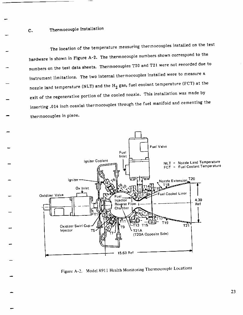
CiThermocouple Installation
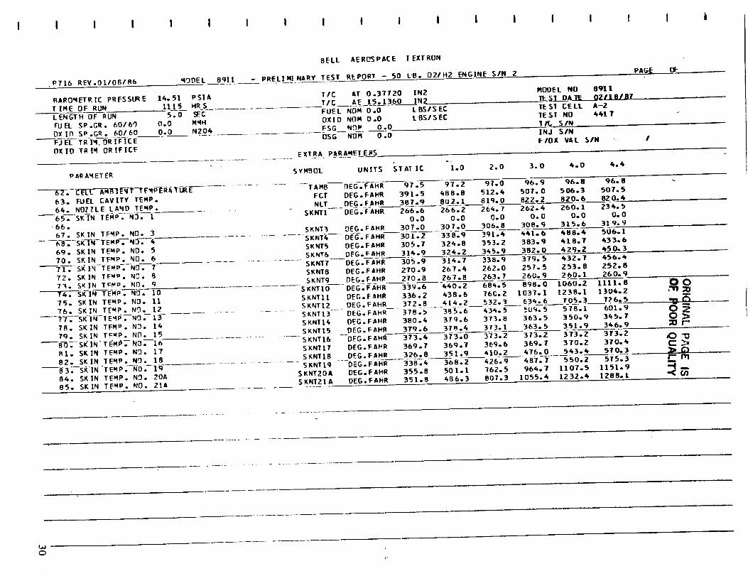
The location of the temperature measuring thermocouples installed on the test
hardware is shown in Figure A-2. The thermocouple numbers shown correspond to the
numbers on the test data sheets. Thermocouples T20 and T21 were not recorded due to
instrument limitations. The two internal thermocouples installed were to measure a
nozzle land temperature (NLT) and the H 2 gas, fuel coolant temperature (FCT) at the
exit of the regenerative portion of the cooled nozzle. This installation was made by
inserting .014 inch coaxial thermocouples through the fuel manifold and cementing the
thermocouples in place.
Igniter Coolant
FuelInlet
r I--'][_ Fuel Valve
-INLT = Nozzle Land TemperatureFCT = Fuel Coolant Temperature
Oxidizer Valve
-I
Ig,
Ox Inlet
Nozzle Extensior T20
Fuel Cooled Liner
Injector 4.39,,rse Flow -t-.... Ref
Oxidizer Swirl Cup
Injector
T19T15
T21A(T20A Opposite Side)
15.63 Ref
Figure A-2. Model 8911 Health Monitoring Thermocouple Locations
23


I I I II I I I ! I I I I I I I
P716 REV.O1/OR_/B6
CHAMBER SIN
INJECTOR SIN----_T_-Em_-S/--_-------7
WI."IDEL
TE ST$
BELL AEROSPACE I EXT RUNPAG_F- OF
BqI[ - PRELIWINARy TEST REPORT - 50 LB. oZIHZ _ENGINE SIN 2...... eZZ-E-OOZ_J+12 - 4J_lT CELL k-2 DATE 02111.8187 -- 021[8181 1ES1 REF*
-- TE S_TH AROWARE_ PROP ELL ANT NOM 1N _1.S O. 0TIC AT(AWE) .37720 IN2 FSG NOR I8OI(_DII
TIC AE( AMEI 15.13G IN2
usG NOM 16OI_,O_ o.0 .ZZ. -_,n.- .o LBSVSEeFUEL NumoXlO NOM .0 LB$1SEC
_EA _,LP.ED
TEST DUp nAT_ _-**_C**** ***q6TlO_'_*
SEC SEC PSI& PERC
S.0 1.0 101.0 0. C 4.1912.0 102.1 O.O 4.167
---------------_[ _2-.9---0:0 --_'"13 9
4.0 lO3.S o.o 4.11o4.4 zo33.6___o?o 4.lOO
O.O
0.0
O. O").O
O.O
4413 5.o 1.o 1oi.8 o.o 6.13q o.o_-0-I-0-2.-_.-o-_, 13o o.o
3.0 !o3.1 o.o r:,.lo8 o.o4.o 1o3.s o.o e.OTB o.o4-._4 _0_.7 _o.o 6.066 o.o
O0"111 _10 4414 ........ O. O
__F:-O---_oz.3 o.o _-.21_
_ z.o 1o2., o.o B.194 o.0_. 3.0 zo3.o o.o s.273 o.o .r-------__4.0 103._-_o,0 8.1_1 o.o
4.4 1o3._ o.o B.142 0.0
_--_-z_ 5.o 1.o lO3.l o.o B.1t'6o.o2.0 103.Z 0.0 B.157 0. O
_ _ ___ _--- --- -3.0-I03.5 _ 0.0 8.138 0.04.0 103.B 0.0 8.120 0.0
FP FFP OF1 I-FI T_ i_A L OPO oPF P A
..... T EST ---_--OR T ESLB/SEC FT/S LBS LeS SEC SEC PS|A PSIA DI:G.FAHR LB-SEC P$10 PSZO es|&
---- . o 344.s o.o 1.788 _=_4.2_. _('- 83. o.o 0.0 0.0 0.042.l_aeBo 8172. ee 4_ _. .... z o.o 1.T_9 3_4. _98. 7,-- BO. __O.O 0.O O.0 0.038
• 98983 _',_31- 69.26 u-u "!_--*__3-_5. 29_- _- 73. 0.0 0.0 0.0 O.03Z" O Tt. 6b* O.O 0.0 0.0 U.028";9_31__,_,-69.B,0.0 3,0., "'"_.80037,._o. __ ._ G.G o.o o.o0.02,
.199584 6299. T0.26 0.0 352.0 O.O X.B_O0 395. 30C. _- o_..199609 6300- TO.31 0.0 352.1 O.O .... ""
- 0,0 O.0 0.0 0.040..... , 0.0 1.027 44b. 231- 79. 87- ___
.210705 5 nBB- TO.I_ o.u ___-£.'-_z;4,-_232. BO. u'_ ....91_-;--7-0-;9_---o.o 336.4 o.o z.B3_ - 6.210827 36.2 0.0 1.834 446. 233. 80. 81- O.O 0.0 0.0 0.031.210937 59_6- T1.33 O.O 3 .... n 1.835 446. 233- B O" TO.__ 0.0 0.0 0.0 O._j-OZ_8_-----
_.a ,, .......... 0.0 O.O O.O 0.028.Z11021 5qb1. Tl.T0 O*0 _:,-;---_-_-L-_036 44b. 233- 80. 74.
.21107T 5966. 71'T9 0.0 _,l._u.t u._ -
0.0 O.O O.O 0.039_ --_5--_93 195. uu. -
.22_._50 5521- 7-1-_,4"3 O.O 317-5 u.u " 96 01. ft. 0.0 0.0 0.0 0.034
.225027 5541. 71.90 O.O 319,5 O.O 1.857 493. I - _ - O 0 0.0 0.03].qb. 81 T4. u._u ,-,-- Z-,_ .--_T2.ZO O.O 320-I O.O 1.858 4q4. I _ "" __'_ n n 0.0 0.0Z8
.225131 5558. 72,42_-0_0_321--.5-----O*O--1--8-50--494-_ i_b. eL. 71. u.u ,,--o o.0 o.o 0.028
. 225287 5570-.225358 5576,, 72.51 O.O 321-7 O.O 1.8.58 494. 196- 81- TO. O.
.22;034 5509. 71.91 0.0 321-0
.224111 5592- 72.23 0.0 322-5
.22_1o5 5605- T2.43-- 0.0--323-1
.224388 5618- 72.66 O.O 323-8
0.0 1.849 490. 195. BI. 78. 0.0 0.0 0.00.03TqO HI. T-t. O.O O.O 0.0 0-033
0,0 1.8'56 4_1. I _ *____ __-----_ -K-----_-n------0.--0-O,_0301;e_-4_f. 1_t. Bz. --, ...... oo.o o.o o.o o.u o.oz8
O.O 1.856 491- 197- 82. T3.
4416
_41_________ -- .0 "/.817 0.05-.-0--'- F.-0 -122 • 9 02.0 123.3 0. C 7.804 0.0
3.0 123-5 O.O 7.778 O.O
_,0-123.T- O.O 7.743 O.O
4.4 123.9 0. O 7.728 0. O
4_
4.4 103.9 0.0 8.112 O.O .224483 5620. 72.69 0.0 323.8 0.0 1.855 491. 19T- 82. -12. O.O 0.0 0.0 O.OZ!
-_--_ " . . I.B3T 362 145- 80. 80. 0.0 0.0
_.0 1.0 -t_.4 o.o B.13, _.o .1_4029_4. _.22 0,0___!_ _:0--_._--_--1_--"0- 01. 0.0 0.0_-- 75.5_ 0.0 B._3Z 0.0 " .164985 55b1.-52.50--0-0 _I -_ -'- .'u_ 362- 145- BO. 80. 0.0 0.03.0 -15.,o.o o.o . 5o,o o.? ,,o. 8o. o.o4.o _5._ o.o _.1140.0 .1_5106558,. ,2.,_ ?-_ _" _ ;2_z 3_2. 14_. 80. ,.- . 0.0
_7_.0--0_0-8-108 0.0---.165129 5589_--_2_80-00-0319"T u.u • ....
--.._ __,_.___3-:. 03. o.o o.o- .264032 5653.--86_69 0.-_328-3 u .... 0.0 0.0z_.3 o.o 1.e-t1 _B. 240. 84. 82.
sere. _.05 o.o 3.... . 1.B-11 _7B. 241. e_. 7"- 0. O 0.O.264571 _o-_-__--?=_-----_--x----_ R O.O I.u/u _.o. - - 0.0.264710 5678. 8T.3U u.u _''-.Z64-T90 5684- 8T.40 0.0 330.1 0.0 I.BIO 518- 241- 85- T2. 0.0
o.o o.03s0.o _..0290.00.OZb
0.0 0.024
0.0 0.0Z3
o.o o.o3i ....O.0 0.033
0.0 0.031
0.0 0.029
0.0 0.028


i I I i I I i I I I i I I i i i i i I
P716 REV.OI108/86 MOOEt
BARONET R IC PRESSURE 14.51
TIME OF RUN 0q32
I ENGTH OF RUN 5.0
FJEL S_'.GR. 60/60 0.0
(_)_IF) SP.GR. 60160 0.0
_ F'-J_ TR IM DRIFICE
9x ID TR IN ORIFICE
PSIA
HR S
SEC
NMH
N204
8911
P6RAMETE_
63. FUEL CAVITY TEMP.
64. NOZTLE LAND TEMP. __ ....
--65_'SKIN TEMP. NJ. 1
_6.
67. SKIN TFqP. N3. 3
(,-_-.---SKIN-YFMP. NO. 4
6g. SKIN TEMP. N3. 5
70. SKIN TEMP. NO. 6
--- ?1;-SKIN TF_'_>_--N3' -7-
72. SK IN TEMP. NO. 8
73. SKIN TEMP. NO. 0
"_L_ SKiN--T'FMP- NO. tO
75. SKIN T_M_. NO. II
76° SKIN TEMPo N q. 12 .........--- 77_ sKIN-TFW°-. NO. 13
78. SKIN TE _D- NO. 14
7q. SKIN TEMP. Nq. 15
81. SKIN T_MP. N_'3. 17
9_. SKIN TEMP. NO. 18
83-.--SK |N-TEMP% NO. lg
84. SKIN TFWP. N3. 20D
95. SKIN TF_P. N0. 21A
BELL AE RP.S P AC E T EXTRON
- PRFLIMINARY TEST REPORT - 50 LB. 021H2 ENGINE SIN 2
TIC AT 0,37720
TIC AE 15.1360
FUEL NOR 0.0
OXID NOM O.O
FSC, NOM 0 .O
055 NOM O .0
PAGE OF
EXTRA P&RAMETERS __
IN2 MODEL NO 8911
! N 2 IF=._T DA T_._ _ 02/]L 8/81
L BSIS EC TESI CELL A-Z
LBSISEC TESI NO _12IR SIN
1NJ SIN
F/OX VAL SIN l
S Y MP_FIL UNITS STAT IC
.... TAM_'-- DEG.FAHR
FCT OEG.FAFR
NLT DEG.FA_R
SKNT[ DEG.FAER
-[.0 2.0 3.0 4.0 4.4
SKNT3 DEG.FAHR
-- SKNT4 9EG.FAMR
SKNT5 DEG.FAMR
SKNT5 DEG.FAHR
.... SKNTT- DEG'FAHR
SKNT@ DCG.FAER
SKNT? DEG.FAPR
......... SKNTIO PEG. FAHR
SKNTll DEG.FAHR
SKNIIZ DEG.FAHR__
SKNTI3 --DEG. FAHR
SKNT16 DEG.FAHR
SKNTI5 D_G.FAHR
..... SKNTI6 DEG.FAHR
SKNTI/ DEG.FAHR
SKNTL8 OEG.FA_R
........... SKNTLg DEG. FAHR
SKNI29| OEG. FAHR
S KNT21/___ OEG-_FAHR
92.0
76.6
72.5
91.5 90.9 90.5 90.4 90.3
200.6 268.3 295.3 301.3 300.6
390.9 425.2 443.4 452.0 453.3
78.8 7B.B 78.8 78.8 78.8 18.80.0 O.O O.D 0. O O.O O. 0
86.1 _6.0 @b.3 @7.8 93.4 97.4
gO.9 153.3 223.8
98.6 141.3 195.497.8 124.8 161.4
- --9R.5 126.0 164.9
87.6 @go9 B9.g
86.4 R_.4 88.4
83.6 141.7 317,8
85.1 161.7 451.6
77.5 q5.3 181.8
77.5 32.7 121.9
74.1 74.1 74.776.4 76.5 77.0
-- 76,9--76,7 --76.9
74.7 74.7 74.7
72.7 86.6 124.7
287.0 341.3 361.9
252.2 307.6 329.1
200_7 256.3 279.6208.3 269.5 296.5
90.0 90.4 90.7
RB. 9 90.8 92.2
488. S 627.1 614.2
714.9 919.2 986.2
276.0 349.9 374.0
201o0 280.9 309.2
75. E 76.9 17.577.9 79.5 8O.Z
71.3 77.8 78.2
74.8 75.2 15.3
166.6 210.8 229.6
74.9 90.9 131.0 114.4 220.9 239.8
73.9 98.0 139.6 [email protected] 2Z2.8 240.1
79.I 161.6 406.5 594.4 755.3 809.4
OCT
,0
I'-- r'q,=.,.
-<Cab
t,J


I I i 1 I I I I I I I I I I I I I I I
P7|6 RFV.01108/86
BELL AEROSPACE TEXTRON
=43DFL_ Bgt[ -- PRELIMINARY TEST REPORT - 50 LB. 021H? ENGINE S/N 2
BAROMETQ IC PRESSLR E 14.51
TIME OF RUN lo3z------CEfi-GYH-b_ RUN S.o
FUEL SP.GR. 60/60 O.O
OX ID SP .GR. 60160 0.0
FJEL TRIM ORIFICE
OXIO TRIq ORIFICE
PAR6_ETER
62. CELL AMBIENT TEMPERTTURE
63. FUEL CAVITY TEMP.
64. NOZZLE L&ND TE_ p"65. SK IN TEMo. N3. 1
b&.
67.
PSlk T/C &T 0,37720 IN2
.... HR S .... TIC AE 15. I360.__._IN2SEC " FUEL NOM 0.0 LBSISEC
'_MH OXID NOM 0.0 LBSISEC
N204 ............. FSG_N qM 0.0OSG NON O .0
EXTRA P&RA'4ET E RS
S Y qBOL U N ITS
........ TAM8 DEG. FAHR
FCT DEG.FAHR
SKIN TF'4P. N9. 3
68. SK IN--TFMP-.--N3. 4
69,, SKIN TE_'.P. NO. 5
7_. SKIN TFMP. N3. 6
7i-.--SKIN-TEMP. NO. T
72,, SK IN TEwP. N3. R
73. SK IN TFwP. N q. q
74. SKIN TE_4P. NO. I0
75. SK IN TEMP. N3. 11
PAGE
MODEL NO 89I I
II'F=S I_D A._LO.Z L1L.B 1811ESI CELL A--Z
1E ST NO 6413
T _ SIN
OF
]NJ bin
F/UX VAL .'SIN I
TATIC -i.O 2.0 3.0 4.0 ',.4
NLT __ OEGtFAH RSKNT| DEG.FAHR
93.1 93.5 93.0 92°8 92.6 92.6
121.2 299.3 397.8 437°4 452.2 _54.5
___ .11.7,8_ 530,9 591.0 620.3 634.5 6]__. 9I01.I lOl.l 101.0 lO0. T 100.5 100.4
o°0 o.0 o.o u.o u.o 0.0
SKNT3 r)EG. FAHR 104.1 104.1 104.4 105.8 110.3 113.6..... SKNT6 OEG.FAHR 97.4 146. I 201.4 2bb. 3 306.5 324.9
SKNT5 OEG.FAHR 103.4 129o4 162.6 194.1 232.2 248.5
SKNT5 _..DE G.FAHR 103.5 120.6 149.0 179,,3 218.6 ___37.6" SKNT7 DEG. FAI-_ 101.8 121.5 1.50.4 182.0 229°b 262°6
SKNTg DEG.FAHR 9T°5 9'_.0 9El.4 98.0 97.9 98.2
SKNT9 OEGpFAHP 97°5 98.9 98.5 98.,6 9'9.9 I01.0........... SKNTIO DEG. EAHR 109.7 164.3 354.1 540.9 693.8 745°0
SKNTII DEG. FAHR 109o6 I86.9 472.6 74g. T 9TT.3 1053.6SKNTI2 DEG.FAHR lI7.Z 1_,1.6 231.2 344.9 429.4 456°T
76.
77. SKIN TE '4a. N3. 13
78. SKIN TEMP. N3. 14
79. SKIN TEMP. Ngo 150_-- _K IN--_ E_b% - N 3_- I 6
B|. SKIN TEMP. N3. L7
82,. SKIN TEMo. NO. 18
84. SK IN TEMP. NO. 20A
SKIN TEMP. N3,_12 .........
85. SKIN TEMP. N3. 21A
SKNTI3 DEG. FAHR
S KNT 14, DEG. FAHR
SKNTI5 DES. FAHR
S KNTI6-- DEG. F AHR
SKNTIT DEG.FAHR
SKNTI8 DEGo FAHR
SKNTI9 DEG°FAHR
SKNTZOA DEG. FAHR
SKNT2I A DEG. FAHR
O0t'n;o
0.__;v r: .......
_O"o
i,,-m
'--I_
-- 119o3 124.3 169.4 255°3 339.6 369.9
117°I 117.1 I16.8 L16.0 1L5.3 L15.1
119.2 119.2 118.6 II/.q 117.4 llT. 6
---- 117.1 l'i-b.T 117.0 I17.1 117.9 118.3
I14.5 114.5 114.5 114.6 115,.0 115,,,2
95.3 114.8 166.9 227.1 288.2 311.9
97.5 117.6 167.1 222.4 278.1 300.6
I14.1 213.3 469.8 687.2 854,.,2 90803
112.3 200.6 467.3 685°6 8TO° I. 931.2
F,JO_


I I I I I I I I I I I I I! I II I I I
P'7[6 REV.OI108186
BAROMETRIC PRESSU_ E
I I,__Eo__RqN----L-ENGIH OF RUN
FUEL SD.GR- 60/60
['lX 10 S p .C,R • 60160
_F_C-fR 14 O_iF-ICEOF, TO TRIq DRIFICE
_ _ .___gO_EL___?IZ
14.51 PSIA
lO37 __s_ --5.0 _C
O.C) M.H
o.o "4_-04....
pARAMETER
-- --_-2-_--CE't-L_AMB_I E-NT T L-'hP-E_A T UR E
63. FUEL CAVITY TEMP.
64. NOZZLE LAND TEMP- r
w----65_--SKIN--TEWD. ND. l
06.
67. sKIN TE _1°• N9o 3_o _ .--SKI N--T EM P-_-NO.---4 .....
69. SKIN TEMP. NO. 5
?0. SKIN TEMP. N3. 0 .........
--Ti_-SKIN TE up'-N3- T
72. SKIN TEMP. N_. q
73• SK IN TE MP• N3. g
T4. SE-IN--TEM_. _0.--t075. SKIN TEMP. NO. 11
76. SKIN TEMP. NO. L2 ........
_77.- SKIN-TE um_-ND" 1.3
78• SKIN TEMP. NO• [&
T9 SKIN TFMP. _'g. 15 ......
------_-O-_--SK-IN-tE"P-_=N52-16BI. SKIN TEMP. N3. 17
82. SKIN TEMP. N9• IB ....
_83-_--sKIN-TEMP- NO. lq
84. SK IN TEMP. NO. 20A
85. SKIN TEMP NO 21A
BELL AEROSPACE I EXT RUN
2
PRELI_TI NARY TEST REPORT - 50 LB. O2JH2 ENGINE SIN
T/C AT 0.37720 INZTIC _E 15.I_)_60___LNZ-
........... FUEL NOM 0.0 LBSISEC
OXID NOM 0.0 LBS/SI::C
FS_ Nf_M 0.0...... OSG NOM 0.0
PA_E OF
MUDEL NO Bgl 1
_A_IL__QZ/I Sl S;1ES1 CELL A--2
IE ST NO 4_I 4
1 ILS IN
INJ SIN
FIOX VAL sIN
EXTRA PARAMEI EPS
SYMBOL UNITS $1 AT IC, "1.0 2.0 3. O 4.0 4.4
228.0 _-_FCT DEG.FAPR .... "I,,,,. ,. "IF.-_ 2 7BB. 3 E05.8 809.9
NLT OEG°FAHR ZZZ.'_ ' _"'_ "--"'-_'-_- --_-- " --
SKNTI
SKNT3 _SKNT_SKNT5 OEG.FAER 272.4
SKNT6 .... DEG - e AHR----- 269:" 5-
SKNT7 OEG.FAHR 273.3
SKNT8 OEG. FAHR 220.5
SKNTq OEG.FAHR 238 ..9....
SKNTIO OEG.FAHR 281.3
SKNTll DEG.FAHR 294.8
SKNTI2 OEG.FAMRSKNT13 -r DEG. FAHR
SKNTI_ DEG.FAPR
SKNTI5 DEG. FAHR
S KNT 16-- OEG.FAHR
SKNTI? DEG.FAPR
SKN_IB __ OEG. FAHRSKNTI9 DE G " FAI'_R
SKNT20A OEG.FAHR
SKNT2t _ _OE_G..._F__HR
OEG.FAPR 199.1 198.6 191.8 19b.4 195.1 L94.30.0 0.0 0o0 0.0 0.0 0.0
OEG.FAH_ 272._ 272.3 272.1 2_3._ 21B.I 2BI.5
DEG. F AH_---- 251 °B 281.5 324.1 366•1 40T°2 423. B284.3 303.T 326. B 354.9 361-_
267.0 282.8 3|0.9 3_9_. 0_0__ 366.3
280.7 299.2 331.0 315.6 39b.9
217.0 211.0 205.5 201.0 199.4
235.2 229.9 225.5 223.0 222.9
356.9 564.0 762.7 924.8 980.3
371.3 b47.1 911.3 1125.6 L195.6
__ 252.8 284.7 395.9 bOB. T b95_.. 8__. 62_- 2___25 B. _)-------26_.-_--- 3-O-g'.I 3BT.9 ---_ 60.8 .95.6
209.6 209.4 207.5 203.9 199.6 19R. O
21,.. 2 2t3.9 2zz.e 20_._ 2o,..6 zo3.o209.3 209.2 209.2 209.2 209.4 Z09. b
206.8 2015.7 20b. a 206.9 207-3 20"/.5
298-2 320.8 _74.2 431- 6 _8B°9 .__SL__L_-b
291_9_321 • 2 3TI-O 421.4 4TI.T _92.0
296.6 395.6 642.1 843.5 1000.3 I05L-3
293°9 392.4 668.5 909.8 1100-_ 1161.9
O0
"oC)
;Or--
P'rr;
"<oo
hJ_J


L i i i I i i i i i i i I i I i I i
BELL AEROSPACE t EXTRUN
,)716 RFV.01108186 MODEL 8911 - PRELIMINARY TFST REPORT - 50 LB. D21H2 ENGINE S/N 2 PAGI- OF
BAROMETRIC PRESSURET ]ME OF RUN
LENGTH ElF RUN
FUEL SP.C,R. 60160
OXID SP.GR. 60160
FJEL TRIM ORIFICE
OXID TRIM ORIFICE
14.5[ PSIA TIC AT 0.37720101,5 HRS TIC AE 15.1360
5.0 SEC FUEL NOW 0.00.0 q'4H OXID NOM O.O
0.0 N204 FSG NOM 0.0
OSG NDM O .D
EXTRA PARAMETERS
P ARAMETFR SYMBOL UNITS
IN2 MODEL NO 8giLl
IN2 1ESI DAlE 02118/87
L BS/S EC IESI CELL A-2
L BSISEC TEST NO _15
1/T. SIN
INJ 5#N
F/DX VAL SIN
ST AT IC "I.0 2.0 3.0 4. O 4._l .
62. C.EL-L AMBIENT TE,4PER_TURE
63. FUEL CAVITY TFMP.
64. NOZZLE LAND TEMP.65_- 5K IN--T-EMp=.-N3. 1
66.(,7. SKIN TEMP. ND. 3
"68_--$KIN TEMP. NO. 4
67. SKIN TEMP. NO. 5
TO. SK IN TEMP. NO. 671. SK IN TENP-.-NF)-.- 7
72. S_' IN TEMP,, NO. B
73. SK IN TFHP. _'3. 9
74. SK][N--TEMP. NO. 1 r)
75. SKIN TEMO. NO. 11
"r6. SKIN TEMP. _'D. 12
-?7_,,-SK IN-TFMP. N].-I_ ..............
78. SKIN TEMp. N.r). 14
79. SKIN TFMP. N3. 15
.qO. SKIN-TEMP. NO. 16
81. SKIN TFMP. NO. 17
82. SKIN TEMP. N3. 18
83. SK IN-TEM_.-NO. 19
84. SKIN TEMP. NO. 20A
85. SKIN TEMP. NO. 21A
TAMB DEG.FA_R
FCT OEG._AHR
NLT OEG.F_I-_R
SKNTI DEG.FAHR
SKNT3 DEG.FAPR
SKNT_ DFG.FA_R
SKNT5 DEG.FAHR
SKNTb DEG.FA_R
96.1 95.8 95.4, 95.1 95.1 95.1
329..5 455.5 523.5 550.2 562.2 565.0
32.5.3 780.4 818.4 832.1 840.9 ..___3, 3258.7 257.7 256.1 254.1 251.9 2_0,, 9
0.0 0.0 O.O O.O O.O 0.0
320.5 320.3 320.2 321.5 326.8 330.4
---310.6 339.0 --_79.9 620.6 _60.7 416.1
321.3 334..5 354.1 376.5 4,04.0 41 6. t.
3]9.'/' 327.1 342.3 370.0 _,OR.T _26o2SKNT7 ....DEG' FAER 320.3
SKNT8 PEG. FAHR 263.30 0 SKNT? 9EG. FAHP 268.8
.... _ _ ........ _SKNTIO DE G. F A HI_-----333_- J--"
_ 335.0C) _;_ 332.70 _ 33_.1
r- 317.o
. _ J¢)"o _ 317.4C_ _' 317.__a. _) 313.4
I=" _ 366.2• ira- __
S Kt_Tll DFG.FAHR
SKNT12 DEG. FAHR
S KNT13 " DEG. FAHR
SKNTI4 DEG.FAHR
SKNTI5 DEG.F&HR
SKNTI6 DEG.FAHR
SKNT[7 DEG.FAHR
SKNTI8 DEG. FAI-_
328.4 345.9 377.9 _.22.1 _2.2260.1 253.7 247. E 243.0 2_1.5
265.2 259.9 255.5 25_.0 254.0
418.0 636.3 e36.8 995.b 1049.1
419.9 T0z,. 0 964.2 1169.4 1236.2
368.5 k81.8 589.2 669.1 694.5
341.0 386.7 4b0.4 532.5 558._
316.8 313.5 306.4 297.9 294.2
316.8 213.3 307.1 299.3 296. I
317.0 311.0 316.9 311.0 317.0
313.4 _13.4 313.4 313.1 313. B
389.0 441.0 496.3 551.9 574.1SKNTI9
S KNT2OAS KNTZIA
DEG. FAHR 312.8 397.5 44/.5 498.6 549.6 570.2
DEG. FAHR 3_e5.1 468.5 710.5 908.5 1059.9 1109.0
DEG. FAHR 342.3 451.9 739.8 980.3 1165.9 1225.4
OO


I i I I I i I I t I I i_d
I I I I I I
0716 REV.OII38186MODEL 9911 -
BAROMETRIC PRESSURE I4.51
T IME OF RUN 1058
LENGTH OF RUN 5.0
FUEL SP.GR. 6016q 0.0
OX ID S p.Gp- 60160 0.0
_EL tr H--O_iF ICEOXiO TRIM ORIFICE
_SIA
HR S......SEC
MMH
N20_4........
PARAMETER
63. FUEL CAVITY TEM".64. NOZZLE LAND TEMP.
--_6_- SK iN'TEMP-'-N-O-----]'_ ....
66,
67- SKIN TEW_, NO, "_
_SK IN -TEM °_--N-__- 4
6g- SKIN TE WP- NO, 5
70, SKIN TEUP, NO, 6
_TI_---SKI-/_-TEMP- N,_, 7
72, SKIN TFM °- N3, 8
73, SK IN TE 'Ap- ND. q
"-_. Sk-IN--Y E _I_ _-N_-_-O
75. SKIN TEM °- NO, 11
76, SKIN TEMP. NO, 12
_,'FT-_ SK IN- TEMP-,-N_-,- 13
7B, SKIN TE =p- N'I, 14
7g. SKIN TE M_. N3. 15
"-----B-O-_-. S K_ N - T Ew P-_--N C]-_- 1 b
81, SKIN TEMP, NO, 17
82, SKIN TEMP. NO, 18
_8-3_-=5K _N--T EM O-,--NO_--19
84, SKIN TEMP, ND, 20A
85. SKIN TEMP. NO, 2]A
BELL AERCSPACE TEXIRUN
PKELIMI NARY 1ESTREPORT - 50 LB, D2/H2 ENGINE_S/N 2
TIC AT 0.37720 IN2
TIC AE 15.1360 INZ
..... FUEL NOM 0,0 LBSISECI_XID NOM 0,0 LBSISEC
F SG.__NDM 0.0
...... OSG NOM 0.0
EXTRA pARAMETERS
PAGE OF
MODEL NO 891L
]E_SID_Z_/__IESI CELL A-Z
TE $1 NO 4.41 6
1 _ S_N
I.,iJ SIN
FIOX VAL SIN
SYMBOL UNI1,S St,AT [C 1,0 2.0
..... TAMB DEG,EAFR 96,7 g6.5 9E.O
FCT 570.5
NLT 8E0.2
- - SKNTI
3.0 4.0 4.4
--95.6 95.4 9b.6
SKNT_
SKNT_
SKNT_
C'__3_ .....
495.7 599.3 614.1 619.8
817.3 8T_.5 887,..9 890.3
266.5 2E5.5 263- t 262.0 2flL.3
0.0 0.0 O.O O.O 0.0
313.2 313.1 3L4.2 3l_.4 321.3
326.7 356.2 3H6.7 418.1 430. B
321.0 334.4 350. e 311./ 3BI.Z
323.9 33_,. 0 354._ 385./ 400.0
316.8 328.6 352.1 387.1 404.-
266.9 262.6 25B._ 255.8 255._
208.5 205.3 262.9 262.0 262.5
4.10.3 6Ol.1 t'87o5 944.4 998.7
418.1 e47.1 880.6 1075.5 1141.5
396.9 503.6 (_07, 9 688,9 1'[_5,__82.4 bbI.3 516. B
358.7 360.2 346.?
359. E 352.b 349.5
3T3.1 _1 _**b368.4 3_5.3
367.8 305.3
--3O5.2 3_5.4
362.4 362.4362.6 391,.4
DEG,FAI_R 378,5
DEG,FAHR 374.9
DEG,FAHR 267.40.0
DEG, F AHR_ 313.4
DEG'F_HR 307.1
DEG.FAHR 312.9
SKNT6 DE G. F A H___._ 3_20.0
SKNT7 .... DEG. FAHR 312.8SKNTB DEG. F6HR 26q.5
SKNTQ .... r)EG: F AI-iR 210,6
SKNTIO DEG, FAIIR 339.0
SKNTII DEG.FAHR 336.2
SKNT12 DEG, F._PR 363.7
SKNTI3 -- DEG,FA_R 368.3
SKNTI_ DEG,FAFR 368.8
SKNT15 DEG.FAHR 368.3
" - SKNTI5 --- DEG. FAHR 366.1
SKNTI7 DEG,FAHR 362.5
SKNTIB DEG,FAHR 348.0- SKNTI9 ----DE G. F A-H/R 359.6 378.3 616.3
SKNTZOA DEG.FAHR 353.6 _5q.3 674.8
SKNI21A OEG.FAHR 349.6 455.3 70L.2
_
36b.7 366.0 306.1
362.5 362.7 362°8
43b.5 478.0 494.1
_b4.8 494ol 5LO. O861.6 LOLL.6 10_3.3
924.3 1106.8 1167.5
D,J

i I I I I I I I I t I I | I I I I I i
.P716 REV.OIlOBIR6 *43DE L
BARONETR IC PRESSURE 14.51 PSIB
TIME OF RUN 1t1_ HRS
LENGTH OF RUN 5.0 SEC
FUEL SP.GR. 60/69 O.O MNH
OX ID SP.GR. 60/60 0.0 NZOA
FJEL TRI*4.0RIFICEOXID TRIq ORIFICE
8911
BELL AEROSPACE T EXT RON
- PRELIMINARY TEST REPORT - 50 L'B. 021H2 ENGINE SIN 2
t/C At 0.37720 IN2TIC. AE 1_55. 1360 |N2
FUEL NOR 0,,,0 LBSISEC
OXlO NOM 0.0 LBSISEC
FSG NOW O.O
OSG NOR O .0
EXTRA PARANET ERS
PAGE OF
MODEL NO 8911
_F._i_ D_A__IL__g/Z_8/ 8t1E $1 CELL A-Z
TE SI NO 4611. 71/_ SIN
INJ SINFIOX VAL SIN
PARAMETER
63. FUEL CAVITY TEWIP.
64. NOZZLE LAND TEqP.
66.67. SKIN TE'_P. NO. 3
SYMBOL
TAMB
FCT
NLT
SKNTI
SKNT3
....... SKNT_
SKNTS
UNITS STAT 1C -1.0 2.0 3.0 6°0 4.4.
69. SKIN TEMP. NO. 5
70. SKIN TEMP. NO. 6
"-'-'-7-1-_-.-SKIN--TEMP-._--NO. 7
72. SKIN TE Mp- NO. 8
7_. SKIN It__p. NF), q
............ SKNT7 DEG.FAHR
SKNTB DEGo FAHRSKNT9 DEGo FAHP
S KNT I0---- OEG. FAHR
SKNT11 DEG.FAHRSKNT[2 DEG. FAHR
............ SKNTI3 .... DEG. FAHR
S KNT16 OEG.FAHR
SKNTI5 DEG.FAHR
......... SKNTI6 DEG.FAHR
SKNTI7 DEG.FAHR
SKNTI8 DEG.FAHR
.............. SKNTI9 DEG.FAHR
SKNT20A DEG.FAHR
SKNTZLA DEG.FAHR
_SK_ TEMP. NO. 10
75. SKIN TEMP. NO. 11
76. SKIN TEMP. N9--12 .....---?_7_---SK_IN-TE'_P. NO. 13
78. SKIN TEMP. NO. 14
79. SKIN TFWP. NO. 15
_B--O-_--SK'tN-T_M_--hO. 16RI, SKIN TEMP. NO. 17
82. SKIN TEMP. NO. 18
8-3_--SKiN--IEMP. ND. 19
84. SKIN TEMP. NO. ZOA
85. SKIN TEMP. NO. 21A
_EG.FAHR 97.5 97.2 97.0 96.9 9&.8 96.8
DEG. FAHR 391.5 488.8 512.6 507.0 506.3 507.5
OEG. FAHR 387°9 802.1 819.0 822.2 BZO.b 820.6
DEG. FAHR 266.b 266.2 264.7 262.6 260.1 234._o.o o.o o.o o.o o.o o.o
DEG. FAHR 307.0 307.0 306.8 308.9 315.6 319.9-- DE_G.-F-A HR 301.2 338°9 391.6 441°6 488°4 5Ub. I
OEG.FAHR 305.7 324.B 353.2 383.9 618.7 633.6
SKNT6 OEG.FAHR 316.9 324.2 345.9 382.0 429.Z 450.3305.9 316.7 338.9 379.5 63,2.7 656.6
270.9 267.6 262.0 257.5 2.53.8 2.52.8
270.8 267.8 263.7 260.9 260.1 260.91060°2 1111.8339°6 460.2 684.5 898.0
336.2 638.6 76C.2 1037.1 tZ3B. t 130_*-2372.8 414.2 532.3 (:34.6 I05.3 726.5
37 B. _----385 .6----434- 5 =.09.5 --5-78.1 601.9
380.4 379.6 373.8 363.5 350.9 345°7
379.6 378.6 373.1 363.5 351.9 34-6.9
373.6 373.0 373.2 373.2 373°2 373°2
369.7 369.7 369.6 369.7 370.z 370.6326.8 351.9 410°2 476.0 563°6 510.3
_338.4 368.2 426.,_ 487.7 _o.z _T5.3355.8 501.1 "/62°5 964.7 1107.5 1151.9
351.s 686.3 e0t.3 |055.6 1232.6 12B8. 1
0>;or-
K_'oC__=c3I--m


I I I I t I I t I I I I I II I I I
P716 p EV.OIIOBIRb
BELL AEROSPACE i EXI RON
MODEL qqll - PRELIMINARY TEST REPORT - 50 LB. 02/H2 ENGINE SIN 2
TESTS 4418 - 4420 CELL A-2 DATE 02118187 - 0211Bl81 IES1 REF. 911-E-001
TEST HARONARE AND PROPELLANT NOMINALS
PAGE UF
CHAMBER SIN
INJECTOR SIN------fTox---_ v-_r_
TIC AT!A_'BI .37720 1N2
TIC AEIAMB) 15.13(c_ 1N2
FS_ NUM I601603 0.0
OSG NUM 1601601 0.0
pUEL NOR .0 LBSISEC
OXIO NOR .0 LB$1S EC
TEST
NO.
4418
441930.0
442O
_EASIJRFD
DLID DATA ****PC**** ***R_TIO**_ wTOTp N y-F_E_---R 0 UG---iE S T COR .... TEST {OR IESI
SEC SEE PSIA PERC L81SEC FTIS LBS LBS SEC
_.9 1.0 10_.4 0.0 4.107 0.0 .196127 5456. 70.97 0.0 361.9
2.0 104.9 0.0 4.093 0.0 .196551 6427. TO._2 0.0 360.3
3=5-t03=9--o_o_o?o 0.0 .... .tgeg32 6_1o. T0.B6- 0-O 3eo.o
30.0
r 0 C)
E* ***F INF*** **ISP INF**CUR
SEC
CF OFP FFP DE1 FFT 1uTAL DPO DPI"C OR _OIL
INF1 RPULSE
PA
PSJA PSIA OEG.FAHR LB-SEC PSIO PSIO P_IA
4.0 103.3 0.0 4.046 0.0
5.0 103.1 0.9 4.025 0.0
-Io.o-1o3:6--o,o 3.g82 o.ol_.O I04.3 0.0 3.98_ 0.0 .IqR_03 6373. 70.g0 0.0 356.6
2o.o 1o4._ o.o 4.003 0.0 .1_77T 63_g. 71.32 c.o _57.o2q.4 165-_--d;0-4:-0_--0-0 .201471 6346_-?-1.6B 0.0 355.8
0.0 1.802 3gO. 291. B2. 82.
0.0 1.805 3gO. 299. 82. X9.
0.0 }.80B 3gO. 2_9. Bi. 74.
.19T09_ 636_. 70.63 0.0 358.4 0.0 1.812 390. 300. Bl. 61.
.1_7_3B 63_. 70.s4 0.0 3s7.4 0.0 1.s_4 3go. 300. Bz. 62.
.z_8073 6_s6; 7o.4_-_.6-_s_:&--o.o £,eoz 3_0= 2_= 80. 4B.0.0 L.eO2 3S_. 2g_. _6. 4S.0.0 L.eO_ 3_n. 298. 7z. 44.o.o L.BOS 3_o. 29_- 6z. 45.
_o_--[Oa:9----O:O- 6.0qB 0.0- .210507 6053_ T2-:66 0.0 345.2
2.q 104.1 0.0 6. OB? 0.0 .21055_ 6042. T2.6_ 0.0 345.2
3.0 10_.B 0.0 6.071 o.o .1106_7 6041. 72.6_ 0.0 344.84_O--lO_jB--O;O-b. O4g 0.0 .210815 603B. 72.4/---d,0_343-8
5.0 105.0 0.0 6.025 0.0 .210953 6943. ?2.47 0.0 343.5
10.0 105.4 0.0 5. g52 0.0 .211743 6345. T2.53 0.0 342.5
15_O 105.T--0-0 S.q4g 0.0 .212751 6035_ 72.69 0.0 341.7
20.0 106.4 0.0 5.976 0.0 .213977 6042. 73.34 0.0 342.8
29.4 107.3 0.0 6.0)q 9.0 .216022 60)4. 74.25 0.0 343.7
.22346_ 551q- 70.57 0.0 315.8
.223447 5538. 7o.Tg- 0.0 316.81.0 I01.5 0.0 B.203 0.0
2_0 101.g--0-0 _.Ig0 0.0
0.0 I.B36 _45. 231- 7g. 75.
0.0 1.B40 445. 232. 7g- 76.
0.0 1.R37 445. 232. T8. 73.0.0 1.B33 444. 232. T8. 6g.
0.0 1.830 444. 232. 7B. 65.
O.O 1.824 44_j 232-_ T___l_. 51.
0.0 1.823 444. 232. 72. 46.
0.0 1.827 444. 232. 66. 4_.
0.0 1.834 444. 232- 57. 44.
0.0 I.B42 492_ lq4° 83£__8B*
0.0 1.842 453. 195. 84. 88.
3.0 102.2 0.0 8.174 0.0 .223536 5553. 70.g3 0°0 317.3 0.0 1.840 493. 196. 85. 81.
4.0 102.7 0.0 R.L51 0.0 °223712 5578. 71.21 0.0 31B.3 0.0 1.838 4g3. lq6. 85- B4.
5;0-1033.1---0i0 8.121 0.0 .223g03 5594; Ti,3_---O_3iB-._.OZ.B-_g3-_97-_5; 80.
10.0 104.4 0.0 8. OOg 0.0 .225250 562g. 72.0g 0.0 320.0 0.0 1.831 494. 198. 82. 61.L5.0 105.2 0.0 7.qg8 0.0 .22696g 5628. 72.71 0.0 320.4 0.0 1.833 494. zge. 76. 52.
_0,-0_-i_..7-_0.C-B.029 0.0---.22873_ 5612. T3.36 0.0--320.7 0.0 1.840 494. 198. 68. 47.
2g.4 106.3 0.0 8.104 O.O .2312R8 5580. 74.24 0.0 321,0 0.0 1.852 494. 198. 57. 44.
0.0 0.0 0.0 0.035
0.0 0.0 0.0 0.030
0.0 0o0 0.0 U.OZI
0.0 0.0 0.0 0.025
o. o o._o____o.o_o-oz30.0 0.0 0.0 0.020
0.0 0.0 0.0 0.019
0.0 0.0 0:_0 0..019
0.0 0.0 0.0 0.019
0.0 0.0 0.0 0.034
0.0 0.0 0.0 0.030
0.0 0.0 0.0 0.028
0.0 0.0 0.0 0.026
0 0.0 0.0 0.024
0.0 0.0 0.0 O.OZE
0.0 0.0 0.0 0.020
0.0 0.0 0.0 0.0Z0
0.0 0.0 0.0 0.020
o.o o. o___o, o o.033o: o_----o, o o.0 0.03,0.0 0.0 0.0 0.030
0.0 0.0 0.0 0.0280.0 O.0 0.0 0.0Z1
0.0 0.0 0.0 0.023
0.0 0.0 0.0 0.022
0.0 0.0 0.00.OZZ
0.0 0.0 0.00.OZ2
m
r...T. _
C m

I I l I I I I I I I I I I I I I 1 t I
P716 REV.0110_/B6 M3OEL
BARPUETR IC PRESSLR E 14.51 PSIA
TIME OF RUN I[32 HRS
---'L-ENGTH OF RUN 30.0 SEC
FJEL SPoGRo 60/60 0°0 M_H
nx ID SP.SR. 60160 0.9 N204
FJ[-I. T_I'4 ORIFICE
OXlD TRI_ ORIFICE
BELL AERCSPACE 1 EXT RON
8qi| ..... _- PRELI_MI NAR_Y_TEST RFPORT -- _0 LB. 021H2 ENGINE SIN 2
TIC AT 0.37720 IN2
TIC_._ AE 15,,.1360 IN2FUEL NOLO. O.0 LBSISEC
OXID NON 0.0 LBSISEC
FSG NOW 0 o0
..... OSG---NON 0.0
EXTRA DA_ A'4ET ERS ...........
PAGF
MUDEL NO 8911
IESI DA_ q/Z_.L_BI81
1ESI CELL A-Z
TE ST NO 44[ 8
]IC SIN
INJ SIN
FIOX VAL SIN ."
pARAMETER
62. CELL AM_IF-'qTT-EhFER_T_URE ........
b3. FUEL CAVITY TE '_p.
64. NOZZLE L6ND TEMP.
'g 65. SKIN TE _ID. N]. I
66.67. SKIN TE u°. N]. 3
6e. SKIN TEMP,,, NO. 5
70. SKIN TEMPo NO. _,
71. SK I-N TFMP-.--N3_--7
72. SKI_ TEMPo N3. 8
73. SKI'q TI:vP- N3. g
74. SKIN "I"E_'. NO. 10
• 75. SKIN TEMP. N3. 11
76. SK IN TE '_p. N3° 12
----_ 7 _-SK- IN--T EMP Z-N_-_-i 3---
78. SKI_', TF'_,, N]. 14
79. %KIN TEMP. N3. 15
--_ 0 ._SK I_T-T ENrP--_-.--t &-
81. SKIN TEMP. NO. 17
82. SKIN TEMP° NO. 18
84. SKIN TEUPo NO. 20A
95. SKIN TEWO. ,N]. 21A
SYMBOL UNITS
...... "rAMB DEG. FAHP g7.8
FCT DEG.FAHR 387.4
NLT DEG.FAHR 383.9
....... SKNT| DEG. FAHR O.OO.O
SKNT3 DEG. FAI-R 307.1
..... S KNT4--DEC.. F AHR 300.9
SKNT5 OEG. FAHR 304.8
SKNT6 DEGoF AI_R 313o9....... SKNT7 -- DEG. F_HR 304°8
SKNTB DEG° FAHR 270.7SKNT9 DEG. FAHR 270.8
..... SKNTID DEG. FAI_R 337.3
SKNT|| DEG° FAI'R 334°0
S KNT]2 OEG. FAHR 369.2
...... SKNT13 .... DEG. I:AHR 374.8
SKNT[4 DEG. FAHR 377.4SKNTI5 DEG. F6NR 376.3
..... SKNTI6 DE_oFAHR 371.8
SKNT17 DEG. FAHR 368.6
S KNT[8 DEGoFAHR 327°3
............. SKNTI9 DEG. FAHR 339.7
SKNT2_A DEG-FAI_R 353.1
SKNT2IA DEG. F&HR 348.9
OF
STAI IC 1.0 2.0 3.0 4.0 5.0 10.0 16.0
|98.3
190.0352.3
368°5 368°4 360.6 351.1
464°3 503.5 673.1 831o2
_95.6 b._ 8.2 724.° 9 902°1
97.4 9T.1 96.9 96.6 96.5 96.6 96.6
385.4 375.7 365.8 361._ 365°T 336.B 309°[
590.4 568°| 548°4 533.4 521.6 502oZ 491.5
O.O 0.0 68.8 42.8 6[°3 2_7.9 20_.I
0.0 0°0 O. C 0.0 0.0 0.0 0.0
307.1 307.1 30o._ 3|6.5 328._ _b3.9 600°T
3_8.2 603.1 649.7 48_.3 521.6 6_4°6 732°4
335.2 378.0 416._ 453.3 4_O.O 666°| T_Bo_
329°5 359.2 398.0 _42o9 488.2 bbl°l 14b.1
318.6 347.4 389.0 4_0.7 _96.9 _46.4 868.0
269.4 2ES.q 262.7 26U.3 2bOoL 27b.3 308.1
269.6 2_7.0 265°1 264._ 267.8 330.2 41[.6
403°8 581.2 729.4 B34.8 909°6 |029°2 1080ob
41q.3 656°7 870.4 1031.¢ 1|67.1 14_8°2 1479.6
3q2.9 462.8 517.7 _52.3 5T4.2 b91°1 b94.337fi.3 405°9 441._ 48B.9 527ol 67U.1 616.1
376.1 370.8 359.1 344.5 328.8 252._375.5 369.2 357.6 343.0 32T.0 248.0
371o4 371.4 3/1.4 371.4 371.3 362.9
368°3 368.3 368. b
342.0 380.3 422.6
369.2 403.3 449.6461.2 676.2 844.8
4_8.3 664°3 830.7
966°8 1067.6 1232°1 IZZOoZ
946.7 1026.6 116_.5 1154o6
.N- )an-_ _.G.
,0
P"rq-4..(;R


I I I I I I I I I I I I I I I I I i I
P716 REV.O1/ORf86
BAR_METRIC PRESSURE
T I_E OF RUN
LENGTH nF RUNFJEL sP.GR. 60/60
OX In S D._R. 60160
r----- Fj EL--T i_-__ - 0-_- i FTC E
14.51
I132
33.0
0.0
0.0
*4ODE L _911
PSIA
FIR S
SEC
W4H
N2 04.
BELl. AFRCSPAEE T EXTRUN
- PRELIM! N&RY TEST RFPoRT - 50 LB. 021H2 ENGINE SIN 2PAGE OF
T/C AT 0°37720 IN2
TIC AE 15.1360 IN2
MUI_E L NO B911
lEST DAlE O2/181B?
FUEL NOM 0.0
_XID NO_ 0.0
FSG NOM 0°0
LBSISEC
LBSISEC
TEST CELL A-Z
1E $1 NO 441 8
1/C SIN
OSG NOM 0.0 INJ SIN
F/OX VAL SIN
DXID TRIq OP_IFICE
p AR A_ ET En S Y'qB OL
......................... TA_B62. C-EL L--A-q B-TEN-f --T EWP-E_-_T UR E
6_,. FUEL CAVITY TEn'P°
64. NOZZLE LAND TEM_°
--_-e %- SKI N--T EMP .--N3--_ L-
6&,
67. SKILl TF _°. N'_. 3
6 q. SKIN TEqP. NO. 5
EXTPA P_RAWET FPS
FCT
NLT
.............. SKNTI
UNITS S'T AT ]C 20'.0 2q.4
SKNT3 DEG. FAHR
.......... SKNT4 DEC_._F AHR
SKNT5 DEGoFAHR
-- 9EG_. FAI_R ,97.8 96.9 97.1
OEG .FAHR 387.4 299.3 2(4.1OEG.FAHR 383.9 497.6 693°6
DEG .FAMIR 0.0 0.0 O. 0
0.3 0.0 0.0
30T.I 717.7 _160.2
300.9 793.9 e67°q
304.8 875.4 952.2
70. SKIN TE4P. ND. 6
--'7 _-_.-SK IN -Y EM_%-N3 _-?
"t'2. SKIN TE_ _. N9. B
73. SKI_! TF'_ °. NO. o_ "/'-_;_-SICI IT -T_. -NZ) .---10- ....
7S. SKIN TEMP. N3. 11
.t6. SKIN TFMP. N3. 12
----_}'?-o--SK IN 'T EM-P ,_-qr]" - 1-3......
78. SK IN TFMP. N_3. 14
7q. SKIN TEMP. ND. 15
-_-0_ -_R-II',I--T F 'm_3-_- 16
ql. SKlk _ TE_o° N_° 17
92° SKIN TEqP° N]. 18
---83-.--SK IN -IEW-P% _NO-;--I g
84, SKIN TE_ ". N3. 20A
85. SKIN TE_P. N3. 21A
SKNT6
............ SKNT70 C SKNTB OEG. FAHR
.'I'I T,_7"; SKNT9 OEG.FAhR
---- --'-'0- {_÷ ....... S KNII3 DEG. FAHR
0 _ SKNTI[ DEG. FAHR0 _:;:_D r "= ..... S KNTIZ DEG. FAHR
- --- SKNT13 DEG° FAHR
_ SKNI I@ DEG. I-AHR
C_ _:_ SKNTI5 DFG. F AHR
r- rq-- S KNT17 DFG. FAHR
_ SKNTIR DEG. FAHR........... SKNTI9 DEG. FAHR
SKNT20A DEG. FAHR
SKNT21 _ DEG. FAHR
OEG.FAHR 313.9 809.2 877.]
OEG.FAHR----'-364.8 922.3 _11.0270.7 339.5 3_1.2270.8 662.7 504.7
337.3 I097.9 1109.7
334.0 1420.0 1358o7
369.2 590.8 587.7
374. E 650.1 61_,- 2
377.4 167.g 139.8
376.3 15q.7 136.3
371.8 339.1 314.5
368.6 339.9 322.2
377.3 978°7 1170.6339.7 10_8.6 1252.7
353.1 1185.4 1155o0
348.g 1140.I 1125.?
LaJ ............
L_

I I I I I I I I I I I t I I I I I I I
BELL
P716 REV.OIIOBI86 MODEL BDlt
BAROMETRIC PRESSUq E 14.51 PS|A
TIME OF RUN 1[50 HRS
L ENGT-H OF RUN 33.0 SEE
FUEL SP.GR. 60/60 0.0 MMH
OX ID SP.GR. 60/60 O.C) N204
F3_TRIM DE IF ICE
OXID TRIM ORIFICE
- =RELIMI NARY TEST
AEROSPACE TEXTRON
REPORT - 50 LB. D21H2 ENGINE SIN 2
PARAMETER
62. CELL AMBIENT TEMPERATURE
TiC AT 0.,37720 IN2
T/C AE 15.1360 IN2
PAGE UF
FUEL NOM 0.0 LBS/SEC
OXID NOM 0o0 LBS/SEC
FSG NON 0.0
-- OSG NOM 0 .O
EXTRA PARAMETERS
SYMBOL UNIIS S'TAT |C 1"0 2.0
T_MB DEG. FAHR 98.4 98.2 97.8
MODEL NO 891. 1.
I'EST DATE 021].8181
lEST CELL A-ZTE ST NO 441 9
T/C SININJ SIN
FIOX VAt SIN I
3.0 _.0 5.0 10.0 lb.O
97.5 97.5 91.5 91.5 __ 91.5
459.7 454.9 %53.0 439.7 438.0
124.5 722.3 719.6 713.4 699.263. FUEL CAVITY TEMP.
64. NOZZLE LAND TEMP.
65. SK--'Yfi---fEMb_--'N-_. I
66°67. SK IN TFMP. NO. 3
&9. SKIN TEMP. NO, 5
70. SKIN TEMP. NO. 6
7 1. 5K [_-TE u_-N-3-_--7
72. SKIN TEMP. NO. B
73. SKIN TEMP. NO. q
74. SK-II_--'r_]@F_- NO. lO
75. SK IN TEMP. N3. [I
76. SKIN TEMP. N.'I. 12
-----T=/.--SK=IN_T Eh P-_ --N5.--13
78. SK IN TEM p • NO. 14
Tq. _KIN TEMo. NO. 15
--_ =O';-_KTN--_EMO_--N3. lb
81. SKIN TFMP. N3o t7
82. SK IN TEMP. N3. 18
83. SK_I_r-_r_WP_--N_ _--|_
84. SKIN T=:_=°" NO. 20A
85. SKIN TF '_°. NO. 2IA
FCT OEG.FAHR 356.3 426.5 454.1`
NLT DEG. FAhR 353.0 716.9 724.1.
..... SKNTI DEG. FAPR O.O 0.0 0.0
0.0 0.0 0.0
SKNT3 DEG. FAFR 332.8 332.6 332.7S K NT4 .... DEG. FAHR_323-5 --35_.9 397.7
SKNT5 DEG.FAHR 328.6 347.9 378.0
SKNT6 DEG.FAPR 333.7 342°8 362.4............ SKNT7 DEG.FAHR 325.9 333.5 3_2.0
SKNT8 DEG. FAHR 280.8 279.7 275.7
SKNTq D_G. FAHR 279.6 278.1 275.2
SKNTIO DEG. FAHR 337.7 414.9 (:20.3
0.0 0.0 0.0 271.5 263.0
0.0 0.0 0.0 O.O O.O
334.3 340.0 352.0 470.3 620.3442.3 48_.° 5 523.6 619.5 182.2
407.0 437.8 471.8 641.9 181.6393.7 433.4 476.9 669.8 787.b
3B3.% 428.4 481.6 139.3 905.3
271.9 268.9 267.3 284.3 321.8
273.0 212.7 215.2 338.2 430.1
795.3 920.5 1011.9 1214.4 1260o9
SKNT11 DEC,. FAHR 336.9 422.3 6(:2°4 891.3
SKNTI2 D_G. FAHR 345.1 377.0 477.1 563. I
............ S KNT 13_- - De-G- FAMR_ 3 _'B _ 6-- _ 5-2_" _-_ 8 _-I-- 44 O" S
SKNTI4 DEG. FAhR 348.9
SKNT15 OEG.FaHR 349.1
......... S KNT [6- DEG; F_HR 350.2
SKNTI7 DEG. FAHR 347.4
SKNT18 DEG.FAHR 341.6
S KNTI9 DEG. FAHR --353.9
SKNT20A DEG.FAHR 348°7
SKNT2I_ DEG.FAHR 345.1.
348.2 343.5
348.2 343.8
I0_0.6 2237. s 1609.3 11t9.6621.1. 650.6 709.z 719.74_.#---55_.z 700.0 156.4
334.3 323.1 310.9 253.0 209.6335._ 325._ 3_4.0 259._ 2_5.3
349.4 349°4 3_9.4 349.4 349.2 34b.1 340.9347.0 346.9 346.9 347.0 34t7.3 347.5 345.0
360.3 406.9 a58.% 51U.5 561,8 792.6 916.5
377.4 42?°7 479.3 530.3 580.9 828.6 1.048.6
461.5 689.4 874.2 LOO7°O 1.101.3' 1286.9 1.322.7
451.8 683.1 884.1 104;.1 11.64.1 1.438.3 1502.5
"_,N"r__.G.
O0.'rl :_1
OLE
_iT) •r-n]m
t_J


I I ! I I i I I I I ! I I I I I I I I
0716 P EV.OI/08/86 _rJ_E L 8911
BELL AEROSPACE TEXTRON
- PRELIMINARY TEST REPO;_ r - 50 LB. O2/H2 ENGINE SIN 2PAGE OF
BAROM ETR IC PRESSURE
T IqE OF RUN
L ENGT H OF RUN
FjEL SP.GR. 60/60
OX ID SP .GR. 60160
--PJEL TRIM 0_IT-ICE
OXtD TRIH ORIFICE
P AR AM ET FR
I4. SI
1150
30.0
0.0
0.0
PSIAHR S
_C
NIMH
N204
TIC AT 0.37720 IN2t/C AE 15.1360 IN2
FUEL NOM O.0 LBSISEC
OXID NOM O.0 LBS/SEC
FSG NOM 0.0
OSG NOR 0.0
..... EXTRA P&RAMETERS
SYMBOL UNITS STATIC 20.0 29.6
TAMB OEG.FAHR 98.4 97.q 9B.O
FCT OEG.FAHR 356°3 4_3.8 a_l°O
NLT DEG.FA_R 353.0 689.8 688.7
........... SKNTI NEG.FAhR 0.0 0.0 0.0
0.0 0.0 0°0
OEG.F_PR 332.8 755.9 941.8
--DEG_FAHR 323=5 846.9 922. Z
OEG.FAHR 328.6 887ol IOlO.Z
DEG.FAHR 333°7 BS4.q 921.3
lqOOEL NO 091 [TE ST DA E 02118101
TEST CELL A-2
TE SI NO 4.419
T/1_ StN
INJ SIN
F/OX VAL SIN "
z. CELL-L---_-tL_r-l_°-_4-?U_-_63° FUEL CAVITY TEMP.66. NOZZLE LAND TEMP.
-_65. S_IN-TFM°. N3. Z
f_T. SK IN T_P. N_]. 3
6R_-. SKIN TEMP. NO. 669o SKIN TFMP. NO. 5
TO. SKIN TFMO. NO. 6
--71_---S K IN -T EM P-.-N_-7
72. SKIN TEMP. NO. 8
73. SKIN TEMP. NO,. q
75. SK IN TFMP. NO. 11
76. SK IN TEMP. NO. 12
"---7-7-.-SK IN-TF.-o. N3 • [3
7B. SKIN TEMP. NO. 16
7q° _K IN TEM_° N3. |__
"--'--_KT-N--T-_f;---NO. 16
81. SKIN TEMP. NO. 1T
82. SK IN TEMP. NO. IB
_B-3-;--. SK iN-TEMf}"_-Ng- Lq
84. SKIN TEMP. NO. 20A
8_. SKIN TEMP. NO. 21A
SKNT3
SKNT6
SKNT5
SKNT6......... SKNT7
SKNT8
SKNT9
SKNTL0
SKNTII
i;._ SKNII)SKNT[6
!;'! SKNTIS
_-_ S KNT I6_ID r" SKNTI7
I_) "_: ,5KNT 18...... SKNTI?
_> SKNT20Ar" _
SKNTZ1A
,.<_
--DEG.FAHR 325.9 1001.5 LC96.1
DEG.FAHR 280.8 356.4 393.2
DEG.FAHR 279°6 507.0 592.2
DE--G.FAHR 337°1 1263o0 I266.0
DEG.FAHR 336.9 1733.3 1706.9
DEG.FaHR 365.| 720.0 72L. BDEG°FAHR 348.0 774.5 777.2
DEG.FEHR 34B°9 180.5 156.6
DEG.FAHR 34g.1 184.B 161.0
DEG.FAHR 350.2 334.1 321.1
DEG.FAHR 347.4 340.8 333.9
DEG.FAHR 361o6 1126.? 1323.0
DEG. FAHR 353.9 1229.2 I491.2
DEG.FAHR 36B.T I346.0 1336.6
DEG.FAHR 3_5.1 1489°1 1_66.1
+ 'b_._,_ d.G.


I I I I I I I I I I I I I I ! I I I I
P716 PEV.OIInR/86 MODEL 4911 __.
BAROMETRIC PRESS_E 14.51 PSIA
T IME OF RUN 1339 HR S
--_EN-GT-H-OF RUN 30.0 _C
FUEL SP.GR. 60/60 0.0 MMH
OK ID SP .GR. 60/60 0.0 N204
----FJ E_T R] M_ORlfl CE
OXID TRIW ORIFICE
P AR A_ ET ER
63. FUEt CAVITY TEMP.
64. NOZZLE LAND T_MP.
6f_.17o SK IN 1"Eu=. N3. 3
_6-_. =SEiN TEWP_-=N3. 4
69. SKIN TEMP. NO. 5
70. SKIN TEMP. N3. 6
_TT_--SK IN-TE up-- N]. 772. SKIN T_WP. Ng. B
71. SKIN TE u". N]. q
15. SKIN T_qP- N3. 11
76. SKIN TEWP. N_I. 12
7B. SK IN TEMP. N3. 14
7q. SKIN TE'_P. '|'}- tF
-_O._K iN-TE M-_-'N3_ 16
Rl. SKIN TEMP. N3. 17
82. SKIN TEMP. NO. 18
R4. SKIN TFMP. N]. 20A
85. SKIN TEMP. N3. 21A
BELL AERCSPACE T EXTRON
- PRELI _ N_RY TEST KEPOgT - 50 LB. 021H2 ENGINE SIN 2
TIC AT 0.37720 IN2
TIC AE 15o 1360 IN2
FUEL NOm 0.0 LBSISEC
oXID NON 0.0 LBSISEC
FSG NOM 0.0
- OSG NOR 0.0
EXTRA pARAMETERS
SYMBOL UNITS S'TAT IC
--TAMB DEG. FAHR 101.2
FCT DEG.F6_R 121.0
NLT DEG.F.AHR 117-1
" - SKNTI DES. F&_R II0.2O.D
SKNT3 DFG. F AHR 111. L
.... SKNT4 DEG.FAHR 101.9
SKNT5 DEG. F AHR 108.4
SKNT5 _ DEG.FAHR I07-6
....... SKNT7 DEG. FAHR 106.9
SKNTB DEG.FAHR 99.7SKNT9 _EG.F_HR 100.3
.... S KNTIO----DEGo F AfiR I12.6
SKNTll DEG.FAHR 112°8
SKNTI2 DEG.FAHR .118-1
MODEL NO 89].1
1Ebl CELL A-2
TE $1 Nil 4_-Z 0
1/I_ SIN
INJ SIN
FIDX VAL 5IN
-[.0 2.0 3.0
100°8 100.2 100.0
318.1 _27.3 482.2
649.5 125.8 761.9
110.4 llO.1 110.1
0.0 0.0 b.O
lll.l 111,2 112,2
140.2 184o0 233.6
130,1 1.59.2 IB2. q
12!._8 . 144.6 1 f1.6-- llq°2 I_4.3 1-/4.8
101.6 lOO. B I00._
lO0.? 9_.B Io0.0
.... SKNTI3 DEG.FAHR 119.9
SKNTI_ DEG.FAPR 117.0SKNTI5 DEG. FAHR 118.9
SKNTI6 BEG. FAhR 116.5
SKNTI7 DEG. FAHR 114.0
SKNT18 DEG. FAHR 94.8
.......... S KNT l _--- oEG.FAHR 91._.
SKNT_OA DEG, FAHR 116,7
SKNT21A DEG. FAHR 114.9
P AGE OF
187.7 415.9
I81.2 448.9
lh3:7 274.4
124.0 161.4
ll?.l llb. b
llB.q 114.5
4.0 5.0 LO.O Ib.U
99.9 99.9 99.9 _ IO0.b
b42.2
725.0 962.0 1150.6 16:)4,0 1824,9
49B. 5 512.6 592.9_____783.8 B3B.5_
240.4 330°6 409.3 b45.b f_4./
llb. 2 llb.l 11b. b 124.3 129.b
118.2 118.5 119,6 130.1 138.6
116-1 llb,2 l16. b 111*0 l18,Z 131,0 148.3
113.9 113,9 114,2 114.¥ 115,6 12B,Z 1_b,9
113.4 162,2 219.0 279.b 3_9. T b45,Z 913,9
111.1 167.7 223.6 2B1,9 339,# 615,1 81b,3
220,4 484.6 108,0 887,5 1031.3 1315,b lqfO,8
213.2 49q. B 165,2 980,8 11.50,2 1519,B ]1119.0
509.9 527.8 5>2°8 5b0.2
181.9 B02..5 82B.4 839.9 -109.7 109.5 I08.I lOb.2
0.0 0.0 o.o 0.0
116.3 12b. 2 2_4.6 417.b2B0.5 325.3 524.5 bBZ.O
21qo0 249. L _41,8 618.8
Z 07._, 256.2 b25.4 1t6.6217.3 272.b 5ri.3 19U.5
log,4 101,_ 132.8 lgb.1
lOl.b 105.7 182.2 309.b
829. S 983.9 1384.2 151_,B
;Or"
_0"0
_>C3r-- F.]
"<03
L_JO_


i I I I I I I i i i I i i i I i i i ,
P716 REV.OllO_/86 MODEL 89]1
BELL AEROSPACE T EXT RDN
- PRELIqI NARY TEST REPORT - 50 LB. DZIH2 ENGINE SIN 2 PAGE OF
BAROMETRIC PRESSLR E 14.51 PSIAT [HE OF RUN 1339 HRS
TIC AT 0.37720 INZ
TIC AE 15,.,1360 IN2
IqOOE L NO B9111
IESI DAIL; OZI| 8181
LENGTH OF RUN 30.0 SEC
FUEL SP.GR. 60160 0.0 MqH
OXID SP.GR. 60160 0.0 N204
FUEL NDM 0.0
OXID NOM 0.0
FSG NOM 0
FJEL TRIM DR IF ICE
DXIO TRIM ORIFICE
PARAMETER
OSG NOM 0
..... EXTKa _araMEt ERs
SYMBOL UNITS
LBS/S EC lEST CELL A-Z
L BS/SEC lEST NO kk20
.0 T/_ S IN
.0 ]NJ SINFIOX VAL 51N _
STATIC 2-0.0 29.4
62. CELL AMBIENT TEMPERATURE
63. FUEL CAVITY TEMP.
64. NOZZLE LAND TEMP.
_5. SK IN TEMP. N3. 1
66.
67. SKIN TEMP. N3o 3
--6_- SK IN-TEMb-.--KJ3. 4
f_9. SK IN TEMP. N3. 5
TANB
FCT
NLTSKNT1
SKNT3
SKNT_
SKNT5
DEG.FAHR lOt. Z I00.8 101.3
DEGoFAHR 121.0 564.0 56b.4
DEG.FAHR 117.1 B44.6 848.6
DEG.FAHR 110.2 105.0 104.00.0 0.0 0.0
DEG.FAHR 111.1 577.6 809.2
DEG.FAHR 101.9 796.3 932.2
DEG.FAHR 108.4 757.7 931.6
TO. SKIN TEMP. N3. 6
?-i-_.SK-IN TEq o. NO. 7
72. SKIN TE'4P. N3. 8
73. SKIN TFMD, N3. 9
74. SKI'S" TEMP. N3o 10
75. SKIN TEMP. N_'I. 11
76. SKIN TEMP. N3, 12
77, 'SKIh--TEMP .--N-3-_ 13
7B. SKIN TEMP. N3. 1470. SKIN TEMP. N."). 15
BO'_'S-'K-J-N--TEWPo N3. 16
81. SKIN TEMP. N3. 17
82. SKIN TEMP. NO. 18
83. 'SK-IF_'-T-£-MP. N]. lg84. SK IN TEMP. NO. 20A
B5. SK IN TEMP. N3. 21A
SKNT6 DEG. FAHR 107.6 838.7 964.4SKNT7---- DEG_F AHR 106.9 934.Z 1084.5
SKNTB OEG. FAHR c_9.7 262.2 365. bSKNT9 O_G.FAHR 100.3 414.1 ",40.7 0 C
SKNTIO DEG.FAHR 112.6 1554.9 1515.8
SKNTII DFG.FAHR l12.B 1884.4 1_09.5
SKNTIZ DEG.FAHR 11B.1 fl60.1 BB2.3
SKNTI3 OEG.FAHR" 119.9 --795.6 843.8
SKNTI4 DEG.EAHR 117.0 131.8 131.7SKqT15 DEG. FAHR 118.9 141.8 142.9
S KNTI6 DEG.FAHR 116.5 164.6 IBl. O
0 :::
SKNTXI DEG. FAHR 114.0 165.9 194.9
SKNTI8 DEG. FAHR 94.8 1130o0 1411.4SKNTI9 OEG. FAHR 97.4 1106.5 1430. 1
SKNT20A DEG. FAHR lib.7 1500.9 1519.8
SKNTZIA DEG. FAHR 1]4.9 1754.0 1773. B
C_ '_,
-,.j


, iI I t i i I I I I I t I i i I i I
CELL = A-2 4421
T3T_L
OA TE
ULSE
PULSE NO. PC FA
= 02/I9/87
F3 AVG I: ON TI'4E OFF TIME OFP FFP P&
1 6.78296 11.50262
2 7.28537 t2._20313 7.37450 12.}0637
4 7.43036 13.13325
5 7.34861 13.2q057
6 7.3452q I3.16827
7 7.43q41 12.97334
7.30737 I2.R7279
q 7.7580_ 13.I3913
[0 7.33633 13.17255
11.51332 11.50797 0.230 0.0
12.83449 12.82760 0.2900_200 ....
[2.91613 12.q1125 0.200 0.200
13.1t339 t3.1083l 0.290 0.200
[3. zo+6t [3.zo25_ 0.230 o.zoo13%tTl-_O_--13_16993 -0.230 0.200
12.97752 12.g7343 0.230 0.200
12.87783 12.9753LO.230 0.200
t3.14455 13.1_184 0.290 0.200
13.17815 13.17464 0.200 0.2000.2}0 0.200
It
t2
13 7.35717
14 7.36847
15 7.07237
SUM ITOT= 10q.44823
oVERALL SU'4 IT3T =
7.27715 t2.5_i80 12.69q34 t2.58567
7.34_[-8-T3-_-0_629---13-.06215--[3_03922 0.230
t3.l_7lq 13. lSqll 13.1581& 0.230[2._3651 12.qtOst 12.q0B41 0.290
12._833q 12._43_ 12.483R6 0.233
193.12422 193.21559 [g3.16q88193.16988
7.29655 12.874q6 12_88104= i2.87800 0.230 0.200
6.782O6 11.53262 11.51332 It.50797
7.4394[ 13.29057 13.2q461 13.20258
O+ i 5533--0._3067 - -0.42q40 0.43003
15 15 15 15
MIN=
MAX=-_ G_=
S AMPL ES =
552.7 341.2 0.0422
566.3 352.3 0.0557
561.7 352.t 0.U615
561.5 355.5 0.0631
567.0 356°2 0.0636
567.1 356.5 0.0644
567.3 356.6 0.0655
567.3 35_.4 0.0660
567.6 356.7 0.0668
567.4 356.6 0.06F5567._ 356.8 0.0676
0.200 567.5 356.7 0.0684
0.200 567.7 356.6 0.0690
0.200 567.7 357.1 0.0693
0.200 567.? 357.2 0.069t
SUM x= 0. t_94483032225_6-2-0-03--3, tq312_gf03698fO 03 O.t9321566295623?BO 03 0,193t6qqSZ39257BtD 03
SU_ X**?= O.Tq_qTnO88378qO62D 03 0.26890660106201170 36 0.26914008941650390 06 0.26902310333251950 04
PULSES O_ITTEO FRO_ STATISTICS= 0 00 0 O_ 0 0 0_0 0 0 0 0 0 0 0 0 0 0 0 0
Symbol Units
PC = Impulse PC ..............
Chamber Pressure x Throat Area x Time, = Ib-sec
FA = Thrust Bridge A, Ib-sec
"-- FB = Thrust Bridge B, ILPsec
AVG F = Thrust Average, Ib-sec
ON TIME sec _ _"m
OFF TIME sec
OFP = Oxidizer Feed Pressure, psia _"_10r"
FFP = Fuel Feed Pressure, ps_a ......
PA = Test Cell Pressure, psia _
_ _,G3................. r" rrli


t i I I f I ! I t I I i 1 I I I I l
CELL = A-2 6422 DATE = 02/1_/B7
TOTAL ]_ UL SEPULSE NO. PC FA FB AVG F ON TIME OFF TIME OFP FFP PA
L 3,Q024_ 6.41752 6- 425?-8 6.42140 O.LZO 0.0 552.1 338.2 0.061 1
2 . 4.20153 7._058L 7.31646 7.31013 O. IZO 0.120 555.2 345.5 0.0687
3 4.0620L 7.I 3165 7.19151 7.18658_----- O. 121 O.Ilq 554.1 ]52.9 0°0559
4 4.1o831 7.24225 7.26889 7.24557 0.120 0.119 554.5 356.5 0.0602
g 4. iRa.Tt 7.65988 7.464l 0 7.66199 O.L _-0 0.120 554.7 356.7 0.0623
6 6.02q73 7.09324 7.19172 7.09748 - 0.120 0.120 554.7 357.2 0.06326.8R349 6. _7908 0.120 0.120 554.8 357.3 0.0629
7.35843 7.354L8 0.120 0.|20 554.7 _57.3 0.0631
7.36M0 ---7'36256 0.120 0.120
7.33527 7.33196 0.120 0.120
7.41095 7._0829 0.120 0.120
7.51696 7.51418-- 0.120 0.120
7.31073 7.30775 0.120 0.120
7.39342 7.39135 0.120 __ 0.120
--7.45118- 7.64936 .... O.L_O 0.120
108,67088 108.77_43 198.7216315
SUM ITOT=
7 3.956_6 6.87467
q 4.15389 7.36993
9 4. 1774Z 7_. 3 SgO1
I0 4. I1788 7.32865
[l 4.73771 7.4)544
12 4.19=5_-----?.5 1 l 40
13 6.15871 7.30477
I_ 4.16773 7.33927
z_.-i7822 7. _4769
61.89136
554.8 357.2 0.0628
555.1 357.4 0.0628
554.8 357.4 0.0646555.0 ]57.4 0.0655
554.9 357.4 0.0638
554.9 357.6 0.0649
555.1 357.6 0.0645
OVER_,LL SU _1 ITOT = 108.72153
MIN= 3.90268 6.61752 6.42528 6.62160_x= 4.23771 7.51140 7.51696 7.51618
S'i C,MA= ()-.09811 (3-_2 7926 0.27828 0.27877
S AMPL ES= 15 15 [ 5 15
SJM x= 0.6189167z91666728r) 02 0:_-0_(_75-97949991995 03 0.10877250099182130 03 0.I0872173690795900 03
SUM X*$- 7-- 0.25550S06210327150 03 0.78838389587402340 03 0.78984796142578120 03 0.78911570739746090 03
PULSES OMITTED FgOW STAIISI_ICS=..___ O. _ 0 0 0 O. 0 O0 0 0 0 0 0 0 0 0 0 0 0 0 0
Symbol Units
PC = Impulse PCChamber Pressure x Throat Area x Time, = Ib-sec
FA = Thrust Bridge A, Ib-sec
FB Thrust Bridge 8, Ib-sec
AVG F = Thrust Average, lb-sec
ON TIME = sec
OFF TIME = sec
OFP = Oxidizer FeedPressufe, psia
FFP = Fuel Feed Pressure, psia
PA Test Cell Pressure, psia
OOT
o_O_
c_
t__D

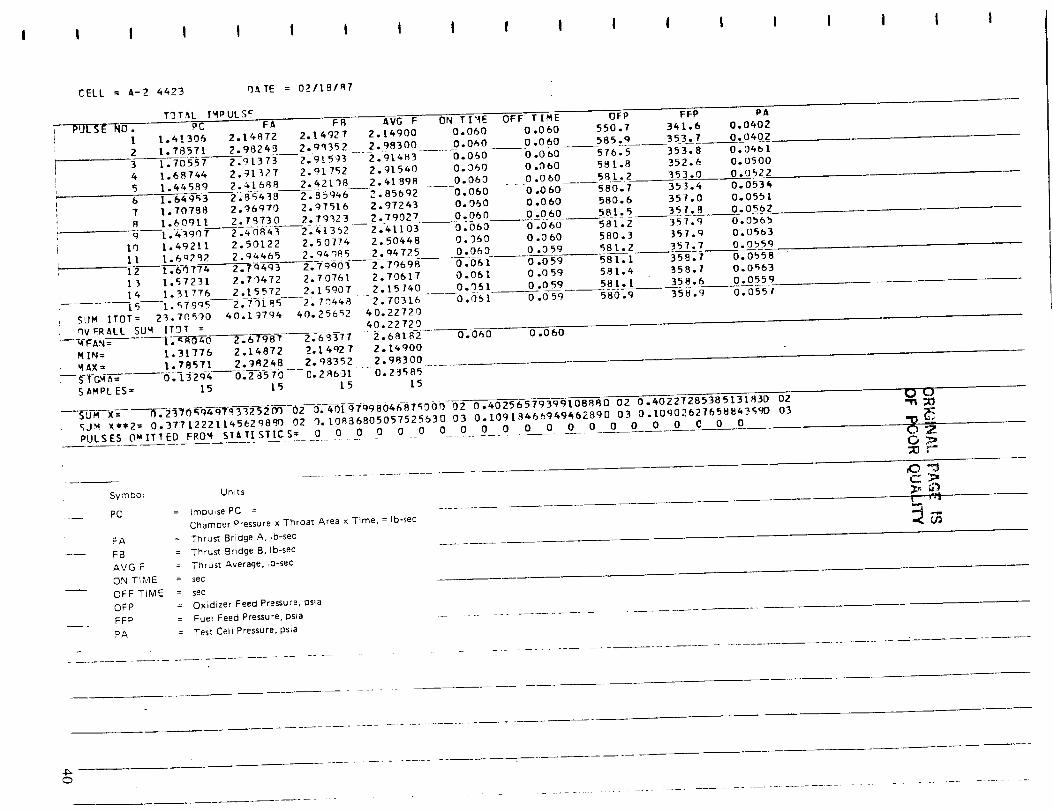
I I I t I I t I t ! I I i I I i I I
CELL = A-2 4423 r}_TE = 02118197
TPT_L IMPULSE
-- PULSE _0o PC F_I 1.41306 2.14972
2 1.78571 2.9824_
3 1.70557
SUM
4 1.68744 2.91327
5 1.64589 2._1888
6 i_ s43B7 1.7o7B8 2._qvoB 1.6o9t1 2.r_73og _ 43907 2_J843
lÙ 1.492t1 2.50122
ll 1.6q292 2.94465
12 t_6-0774 2.Tq6g3
13 1.57231 2.79472
14 1.31776 2.15572
[-_---f;_7995 2;7_i_sITOT= 23.70590 40.[9796
I 8 AVG F
2.14927 2.14900
2-qq352 2.q8300 ....
2.91373 2.915_3 2.914832.91752 2.91540
2.42138 2.4[ 898 ___
2.85946 2.85692
2.97516 2.97243
2.79_23 2.79027 ....
2.6L362 2.41103
2.50774 2.50668
2.9_.9_5 2.q4725
2.70761 2.70617
2.15907 2.15740
2,,7a448 2.70316
40.25652 40.22T20
ON TIME OFF TIME OFP FFP PA
0.060 0.060 550.7 341.6 0.0602
0.080__ 0.060 585.q 353.7 0.0_02
0.050 O.ObO 576.5 353.8 0.0601
0.360 0.060 581.8 352.6 0.0500
0.060 0.060 581.2 353.0 0.0522
0.060 .... 0.060 580.7 353.4 0.053_
o.9_o 0.060 _so.6 351.o o.os_l0.060 0.060 581.5 357._ 0.05920.060------0_060---------58|-2 351.9 O.Ob6b
0.3_0 0.060 580.3 35_.9 o.osb30.0_0 0.059 581.2 _57.7 0.0bs_o.o61 0.059 581.1 35B.7 0.0658o.o61 o.o59 581.4 358.7 o.o_630.q51 0.059 581.1 358.6 0.0559
-----o;osf o.o59 58o.9 35u.9 o.o5_t
, MIN=
MAX=
i r3vgRALL SUM ITDT = 40.22720[ ._-9-O'TO------f?. &798-_ 26 _ 3T 7 -- 2 • 68182 0.060 0.060
1.31776 2.16872 2.14927 2.16900
1.78571 2.9R248 2.98352 2.98300
O.-L 32q4 0.-2-8-570 0.2R631 .... 0.29585
SAMPLES = 15 15 [5 15
__._S___M___ _2_0-_-q_-_2-5-_-02--_-.-#01 gTqgB06687_909 02 0.60256579399108880 02 0.40227285385131830 02
(;JM X**2 = 0.37712221145629890 02 3. t08i]6805057525630 03 0.10919466949462890 03 0.t0q0262765884359D 03
PULSES OalTTED FROM ST_TISTICS__ 0 0 0 0 0 0 0 0 0 0 0 0 0 0 0 0 0 0 C 0 0
-n;O
tgO__r"
,c) -r3.............. c_3;=
Symboi Units _'_ _)
PC : Impulse PC .... _ ._.Chamber Pressure xThroat AreaxTime =tb-sec Gr_
FA Thrust Bridge A Ib-sec
FB Thrust Bridge B, Ib-sec
AVG F = Thrust Average, lb-sec
ON TIME = sec
-- OFF TIME = sec
oFP = Oxidizer Feed Pressure, psia
FFP Fuel Feed Pressure,psia -- --
PA = Test Cell Pressure psia
O

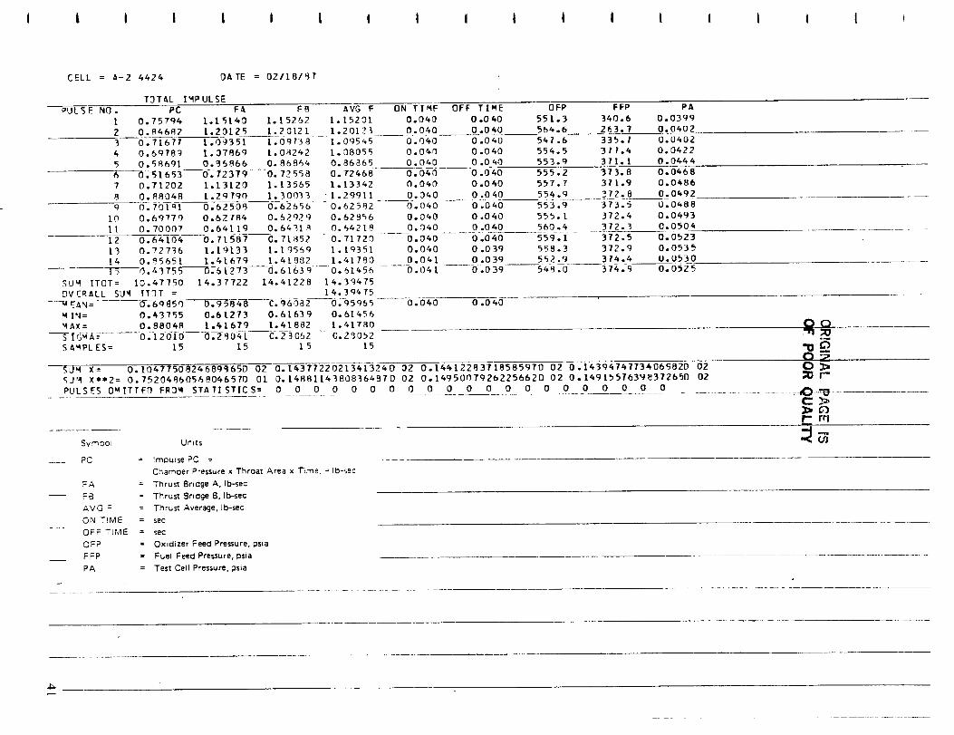
I | i i ! i i i I I i i i i i I i i
CELL = A-2 4424 DATE = 0Z/18/97
T3 T _,L IMPULSE
PULSE NO. PC FA FB
1 0.75794 1.15140 1.15262
2 0.84682 [.ZOIZ5 1.2312[
3 0.71677 1.0935I 1.09738
4 0.6978g 1.37869 [.0_242
5 0.58691 0.35866 0.868546 O_51653 0.72379 .... 0.72558
7 0.71202 1.13[20 I.I3555
8 0.88048 [.2g790 1.300339 0.701ql 0.62509 0.62656
10 0.6q770 0.827R4 0.52q29
11 0.70007 0.64119 0.6431 q
12 0.64104 0.7[587 0.7[852 --
13 0.72736 1.19[33 1.19569
I4 0.9565l I.%[67g 1.4[_S2
AVG F
1.1520[
1.20123
1.09545
1.08055
0.86865
0.72468
1.L3342
1.29911
0.62S82
0.629S6
0._4218
0.71720
l.lq351
1.41790
In_--r)_r3755"-----7)_$12_3 0.6[639 -- 0.61456
SUM ITOT= 10.47750 14.37722 14.41228 14.30475
OVERALL SUM ITgT = 14.39475
----_A N= 0_q-_5 r) O. 958-4-8---C. g 6 O_ 2 0.95965
WIN= 0.43755 0.6t273 0.61639 0.61456
MAX= 0.88048 1.41679 1.41882 1.61780
S I_'_*A: -- 0,-120[(J---(]--2904I C.29062 --C.29052
SAMPL ES = 15 15 15 15
$0_ X=
ON TIME OFF TIME OFP FFP PA
0.040 0.040 551.3 340.6 0.0399
0.040 0.040 564.6 263.7 0.0402
0.040 0.040 547.6 335.1 0.0402
0.040 0.040 554.5 377._ 0.0422
0.040 0.0_0 553.9 371.1 0.0444
0.040 0.040 555.2 373.8 0.0468
0.040 0.040 557.7 3t1.9 O.0_86
0.040 0.040 554.g 372.8 0.0492
0.040 0.040 553.9 373.5 0.0488
0.040 0.040 555.1 372.4 0.0493
0.040 0.040 560.4 372.3 0.0504
---0.0_0 0.040 559.1 372.5 0.0523
0.0_0 0.039 558.3 372.9 0.0535
0.04[ 0.039 552.9 3?4.4 0.0530
......0.041 ..... 0.039 548.0- 3?4.9 0.0525
0.040 0.040
0,104775082468gS65D 02 0.14377220213413240 02 0.14612283718585970 02 0.14394747734069820 02
O0"11;::0
o_gJM X**2= 0.75204960568046570 O1 0.[4881143808364870 02 O.1495007926225662D 02 0.1491551639e372650 02
PULSES O, ITTED FR3M STATISTICS = 0 0 0 0 0 0 0 0 0 0 0 0 0 0 0 0 0 0 0 0 0
SymOOI Units
PC = Imou_se PC =
Chamoer Pressure x Throat Area x Time, = Ib-sec
FA = Thrust Bridge A, Ib-sec
FB = Thrust Bridge B, Ib-sec
AVG F = Thru_ Average. lb-sec
ON TIME = sec
OFF TIME = sec
OFP = Oxidizer Feed Pressure, psia
FFP = Fuel Feed Pressure, psaa
PA = Test CellPressure,psia
_r-
C>
_m
