final report rl 2016:07e - havkom · final report rl 2016:07e aircraft: registration, type se-mdb,...
TRANSCRIPT
Final report RL 2016:07e
Serious incident during approach to Visby
Airport on 30 November 2014 involving
the aircraft SE-MDB of model ATR-72-
212A, operated by Braathens Regional
AB.
File no. L-148/14
19-10-2016
RL 2016:07e
Postadress/Postal address Besöksadress/Visitors Telefon/Phone Fax/Facsimile E-post/E-mail Internet
P.O. Box 12538 Sveavägen 151 +46 8 508 862 00 +46 8 508 862 90 [email protected] www.havkom.se
SE-102 29 Stockholm Stockholm
Sweden
SHK investigates accidents and incidents from a safety perspective. Its
investigations are aimed at preventing a similar event from occurring in the
future, or limiting the effects of such an event. The investigations do not
deal with issues of guilt, blame or liability for damages.
The report is also available on SHK´s web site: www.havkom.se
ISSN 1400-5719
This document is a translation of the original Swedish report. In case of
discrepancies between this translation and the Swedish original text, the
Swedish text shall prevail in the interpretation of the report.
Photos and graphics in this report are protected by copyright. Unless
otherwise noted, SHK is the owner of the intellectual property rights.
With the exception of the SHK logo, and photos and graphics to which a
third party holds copyright, this publication is licensed under a Creative
Commons Attribution 2.5 Sweden license. This means that it is allowed to
copy, distribute and adapt this publication provided that you attribute the
work.
The SHK preference is that you attribute this publication using the
following wording: “Source: Swedish Accident Investigation Authority”.
Where it is noted in the report that a third party holds copyright to photos,
graphics or other material, that party’s consent is needed for reuse of the
material.
Cover photo no. 3 - © Anders Sjödén/Swedish Armed Forces.
RL 2016:07e
Contents
General observations ...................................................................................................... 5
The investigation ............................................................................................................ 5
SUMMARY ....................................................................................................... 8
FACTUAL INFORMATION ...................................................................................... 10
1.1 History of the flight .......................................................................................... 10 1.1.1 Preconditions ....................................................................................... 10 1.1.2 Sequence of events .............................................................................. 10
1.2 Injuries to persons ............................................................................................ 11 1.3 Damage to aircraft............................................................................................ 11 1.4 Other damage ................................................................................................... 11
1.4.1 Environmental impact.......................................................................... 11 1.5 Personnel information ...................................................................................... 12 1.6 Aircraft information ......................................................................................... 12
1.6.1 Aircraft ................................................................................................ 12 1.6.2 Description of parts or systems related to the occurrence ................... 13
1.7 Meteorological information ............................................................................. 17 1.8 Aids to navigation ............................................................................................ 17 1.9 Communications .............................................................................................. 17 1.10 Aerodrome information ................................................................................... 17 1.11 Flight recorders ................................................................................................ 17
1.11.1 FDR ..................................................................................................... 17 1.11.2 Cockpit Voice Recorder (CVR) .......................................................... 18
1.12 Site of incident and the aircraft after the incident ............................................ 18 1.12.1 Site of incident ..................................................................................... 18 1.12.2 The aircraft after the incident .............................................................. 18
1.13 Medical information......................................................................................... 20 1.14 Fire ................................................................................................................... 20 1.15 Survival aspects ............................................................................................... 20
1.15.1 Rescue operation ................................................................................. 20 1.15.2 Position of and injury to those on board, and use of seat belts ............ 20
1.16 Tests and research ............................................................................................ 20 1.16.1 Propeller examination .......................................................................... 20 1.16.2 Engine examination ............................................................................. 20 1.16.3 Stress calculation of the actuator and trunnion pin .............................. 21 1.16.4 Examination of actuator....................................................................... 21 1.16.5 Analysis of FDR and CVR data .......................................................... 22 1.16.6 Analysis of background noise from the CVR ...................................... 23 1.16.7 Simulator tests ..................................................................................... 24 1.16.8 The manufacturer's flight tests ............................................................. 24
1.17 Organisational and management information .................................................. 24 1.18 Additional information..................................................................................... 25
1.18.1 Previous incidents of a similar nature .................................................. 25 1.18.2 Incident involving SE-MDC ................................................................ 25 1.18.3 Basic principles for aeroelastic vibrations ........................................... 25 1.18.4 Actions taken ....................................................................................... 26
1.19 Useful or effective investigation techniques .................................................... 27
2. ANALYSIS ...................................................................................................... 28
2.1 The flight .......................................................................................................... 28
RL 2016:07e
4 (32)
2.2 Damage to the propeller mechanism ............................................................... 28 2.3 Damages to the engine, etc. ............................................................................. 29 2.4 Measures taken by the propeller type certificate holder .................................. 29 2.5 Measures taken by the aircraft type certificate holder ..................................... 29 2.6 Overall assessment .......................................................................................... 30 2.7 Flight safety assessment .................................................................................. 31
3. CONCLUSIONS ............................................................................................. 31
3.1 Findings ........................................................................................................... 31 3.2 Causes of the serious incident ......................................................................... 31
4. SAFETY RECOMMENDATIONS ................................................................ 32
Appendices- BEA submission ........................................................................... 33
RL 2016:07e
5 (32)
General observations
The Swedish Accident Investigation Authority (Statens haverikommission –
SHK) is a state authority with the task of investigating accidents and incidents
with the aim of improving safety. SHK accident investigations are intended to
clarify, as far as possible, the sequence of events and their causes, as well as
damages and other consequences. The results of an investigation shall provide
the basis for decisions aiming at preventing a similar event from occurring in
the future, or limiting the effects of such an event. The investigation shall also
provide a basis for assessment of the performance of rescue services and, when
appropriate, for improvements to these rescue services.
SHK accident investigations thus aim at answering three questions: What
happened? Why did it happen? How can a similar event be avoided in the
future?
SHK does not have any supervisory role and its investigations do not deal with
issues of guilt, blame or liability for damages. Therefore, accidents and
incidents are neither investigated nor described in the report from any such
perspective. These issues are, when appropriate, dealt with by judicial
authorities or e.g. by insurance companies.
The task of SHK also does not include investigating how persons affected by
an accident or incident have been cared for by hospital services, once an
emergency operation has been concluded. Measures in support of such
individuals by the social services, for example in the form of post crisis
management, also are not the subject of the investigation.
Investigations of aviation incidents are governed mainly by Regulation (EU)
No 996/2010 on the investigation and prevention of accidents and incidents in
civil aviation and by the Accident Investigation Act (1990:712). The
investigation is carried out in accordance with Annex 13 of the Chicago
Convention.
The investigation
SHK was informed on 2 December 2014 that a serious incident involving an
aircraft with registration SE-MDB had occurred upon approach to Visby
Airport, Gotland county, on 30 November 2014 at 12.20.
The incident has been investigated by SHK represented by Mr Jonas
Bäckstrand, Chairperson, Mr Sakari Havbrandt, Investigator in Charge and
Technical Investigator, and Mr Nicolas Seger, Operations Investigator.
The investigation team of SHK was assisted by Ulf Ringertz and Kristoffer
Danèl as technical experts.
Arnaud Toupet from BEA1 participated as an accredited representative for
France, the state in which the aircraft was designed and manufactured, and
1 BEA (Bureau d’Enquêtes et d’Analyses pour la securité de l’aviation civile) – the French authority for
safety investigations in the field of civil aviation.
RL 2016:07e
6 (32)
Carol Horgan from NTSB2 participated as an accredited representative of the
USA, where the propeller was designed.
Björn Pettersson has participated as advisor of the Swedish Transport Agency,
and Alexandre Peytouraux has participated as advisor of the European Aviation
Safety Agency (EASA).
The following organisations have been notified: The International Civil
Aviation Organisation (ICAO), EASA, the European Commission, BEA
(France), NTSB (USA), TSB3 (Canada) and the Swedish Transport Agency.
Investigation material
An initial technical investigation was carried out by SHK in Visby on 2
December 2014.
Interviews have been conducted with the commander.
The Flight Data Recorder (FDR) and Cockpit Voice Recorder (CVR) have
been analysed.
A technical investigation of the propeller mechanism has been carried out.
Two factual information meetings with the interested parties were held on 11
November and 1 December 2015. At the meetings, SHK presented the facts
available at the time.
2 NTSB (National Transportation Safety Board) – the USA's authority for safety investigation in civil
aviation. 3 TSB (Transportation Safety Board of Canada) – Canada’s authority for safety investigation in civil
aviation.
RL 2016:07e
7 (32)
Final report RL 2016:07e
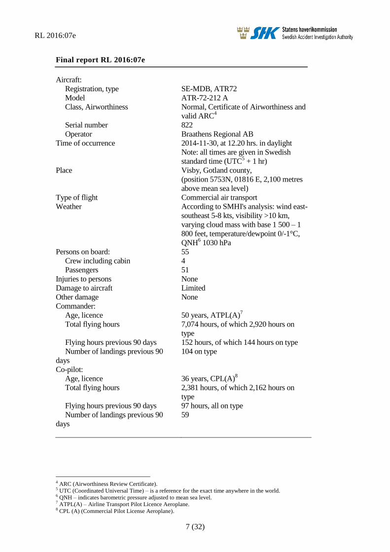
Aircraft:
Registration, type SE-MDB, ATR72
Model ATR-72-212 A
Class, Airworthiness Normal, Certificate of Airworthiness and
valid ARC4
Serial number 822
Operator Braathens Regional AB
Time of occurrence 2014-11-30, at 12.20 hrs. in daylight
Note: all times are given in Swedish
standard time (UTC5 + 1 hr)
Place Visby, Gotland county,
(position 5753N, 01816 E, 2,100 metres
above mean sea level)
Type of flight Commercial air transport
Weather According to SMHI's analysis: wind east-
southeast 5-8 kts, visibility >10 km,
varying cloud mass with base 1 500 – 1
800 feet, temperature/dewpoint 0/-1°C,
QNH6 1030 hPa
Persons on board: 55
Crew including cabin 4
Passengers 51
Injuries to persons None
Damage to aircraft Limited
Other damage None
Commander:
Age, licence 50 years, ATPL(A)7
Total flying hours 7,074 hours, of which 2,920 hours on
type
Flying hours previous 90 days 152 hours, of which 144 hours on type
Number of landings previous 90
days
104 on type
Co-pilot:
Age, licence 36 years, CPL(A)8
Total flying hours 2,381 hours, of which 2,162 hours on
type
Flying hours previous 90 days 97 hours, all on type
Number of landings previous 90
days
59
4 ARC (Airworthiness Review Certificate). 5 UTC (Coordinated Universal Time) – is a reference for the exact time anywhere in the world. 6 QNH – indicates barometric pressure adjusted to mean sea level. 7 ATPL(A) – Airline Transport Pilot Licence Aeroplane. 8 CPL (A) (Commercial Pilot License Aeroplane).
RL 2016:07e
8 (32)
SUMMARY
The incident occurred during a scheduled flight from Bromma to Visby.
The commander has stated that small vibrations were felt during descent, at
around 7,000 feet. The indicated speed was 250 kts and the power levers were
set to idle.
The vibrations increased in intensity and the commander reduced the rate of
descent to 2,500 feet per minute.
The vibrations became so severe that the cabin crew had difficulties moving in
the cabin and that there were difficulties reading the instruments in cockpit.
Information from the flight recorders shows that the left propeller was first
feathered momentarily. The right propeller was feathered thereafter, after
which the right engine was shut off. The flight continued with the left engine in
operation. The information also reveals that the communication between the
pilots did not include confirmation of which engine’s power levers were
manoeuvred. A number of warning signals were activated during the sequence
of events. The signals were not reset during the acute phase of the event.
When the commander moved the right propeller control to feather position, he
was unable to push it all the way to fuel shut-off position. The control was
therefore returned to the “auto” position and then pushed back via the feather
position to fuel shut-off, whereby the vibrations subsided.
The co-pilot explained the situation to the air traffic controller in the Visby
tower and declared an emergency situation. The air traffic controller triggered
the alert signal.
The approach and landing were executed without problems.
The investigation revealed following damages:
The eccentric trunnion pin on blade no. 2 was ruptured.
The front propeller pitch change actuator plate was severely bent
on all six positions.
The engine mounts had received damage from contact with metal.
The engine's compressor housing was cracked along half of its
circumference.
The shaft of the AC generator was ruptured.
SHK has been unable to establish the cause of the serious incident.
RL 2016:07e
9 (32)
Safety recommendations
SHK's assessment is that additional extensive engineering initiatives are
necessary in order to find the cause of the incident and that such initiatives
should be the responsibility of the aircraft and propeller type certificate
holders, under supervision of the certifying authorities. It has also been
possible to establish that the known incidents of a similar nature have taken
place under similar circumstances. In light of this, the following recom-
mendation is issued. EASA is recommended to:
Consider introducing temporary limitations in the
manoeuvring envelope, or limitations of the power ranges
within the latter, until the problem is resolved and rectified.
(RL 2016:07 R1)
RL 2016:07e
10 (32)
FACTUAL INFORMATION
1.1 History of the flight
1.1.1 Preconditions
The incident occurred during a scheduled flight from Bromma to
Visby. The flight, which was conducted with an aircraft of model
ATR-72-212A, had flight number DC929 and was operated by
Braathens Regional AB.
Four crew members and 51 passengers were on board.
Preparations and planning were carried out in accordance with
standard procedures.
1.1.2 Sequence of events
The cruising altitude for the flight was Flight Level 140,
(4,300 metres). There were clouds at this altitude, and the temperature
was -7°C. The pilots established that ice was forming on the aircraft
and decided to activate the de-icing systems. The systems had the
intended effect, and it was established that the ice which had formed
on the front edge of the wings disappeared.
The commander has stated that small vibrations were felt during
descent, at around 7,000 feet. The descent rate at this point was 3,200
feet per minute, the indicated speed was 250 kts and the power levers
were set to idle. The commander pushed forward first the left and then
the right power levers, as previous experience had taught him that the
vibrations tend to cease when moving the power levers forward from
idle position. However, the measure had no effect on the level of
vibrations.
The vibrations increased in intensity and “PEC9 fault” was indicated
via the aircraft's warning system. The commander reduced the rate of
descent to 2,500 feet per minute.
The vibrations became severe and the pilots noted the triggering of the
red “master warning” light. The commander moved the right propeller
control to feather position but was unable to push it all the way to fuel
shut-off position. The control was therefore returned to the “auto”
position and then pushed back via the feather position to fuel shut-off,
whereby the vibrations subsided.
Information from the flight recorders shows that the left propeller was
first feathered momentarily. The right propeller was feathered
thereafter, after which the right engine was shut off. The flight
continued with the left engine in operation. The information also
reveals that the communication between the pilots did not include
9 PEC – Propeller Electronic Control.
RL 2016:07e
11 (32)
confirmation of which engine’s power levers were manoeuvred. A
number of warning signals were activated during the sequence of
events. The signals were not reset during the acute phase of the event.
The commander informed the cabin crew that one engine had been
shut down and that the landing would be normal. The co-pilot
explained the situation to the air traffic controller in the Visby tower
and declared an emergency situation. The air traffic controller
triggered the alert signal.
The approach and landing were executed without problems. The roll-
out was conducted without reversing. Once the aircraft had been
parked, the commander informed the passengers about the incident.
He then conducted a debriefing with the crew.
The rescue services at Visby Airport attended the scene with three
vehicles but did not need to take any action.
Following the incident, the commander has submitted an incident
report in which he explains that the vibrations were so severe that the
cabin crew had difficulties moving in the cabin and that there were
difficulties reading the instruments in cockpit. He also mentions that
the landing, which was performed using visual references, was
prioritised over reading through the checklists for abnormal
procedures.
The incident occurred at 12.20 local time during the day in position
5753N 01816E, 2,100 metres above sea level.
1.2 Injuries to persons
Crew
members
Passengers On board,
total
Others
Fatal - - 0 -
Serious - - 0 -
Minor - - 0 Not
applicable
None 4 51 55 Not
applicable
Total 4 51 55 -
1.3 Damage to aircraft
Limited.
1.4 Other damage
None.
1.4.1 Environmental impact
None.
RL 2016:07e
12 (32)
1.5 Personnel information
Commander
The commander was 50 years old and had a valid ATPL(A) with
flight operational and medical eligibility. At the time, the commander
was PF10
.
Flying hours
Latest 24 hours 7 days 90 days Total
All types 0.6 5 152 7,074
This type 0.6 5 144 2,920
Number of landings this type previous 90 days: 104.
Type rating concluded on 8 December 2008.
Latest PC11
performed on 28 November 2014 on this type.
Co-pilot
The co-pilot was 36 years old and had a valid CPL(A) with flight
operational and medical eligibility. At the time, the pilot was PM12
.
Flying hours
Latest 24 hours 7 days 90 days Total
All types 0.6 12 97 2,381
This type 0.6 12 97 2,162
Number of landings this type previous 90 days: 59.
Type rating concluded on 31 August 2010.
Latest PC performed on 28 August 2014 on this type.
Cabin crew members
The cabin crew consisted of two persons.
1.6 Aircraft information
The aircraft is a twin-engine, high-wing turboprop aircraft with a short
range. The aircraft is equipped with two adjustable six-blade
propellers.
1.6.1 Aircraft
TC-holder ATR-GIE Avions de Transport Régional
Model ATR 72-212 A
Serial number 822
Year of manufacture 2008
Gross mass, kg Max permissible take off/landing mass
22,800/22,350, actual 20,238/19,822
10 PF (Pilot Flying) – the pilot who is manoeuvring the aircraft. 11 PC (Proficiency Check). 12 PM (Pilot Monitoring) – the pilot who monitors the flight.
RL 2016:07e
13 (32)
Centre of gravity Within permitted limits. CG -1.0 Aircraft
Nose Up (27% MAC)
Total operating time, hours 10,036.8
Operating time since latest
inspection, hours
68
Number of cycles 99
Type of fuel loaded before
event
JET A-1
Engine
TC-holder Pratt and Whitney Canada Corp
Engine type PW127M
Number of engines 2
Engine No 2
Serial number FR20080
755
Total operating time, hours 8,615.9
Operating time since latest
inspection, hours
8,615.9
Propeller
TC-holder Hamilton Sundstrand
Type 568F-1
Propeller No 2
Serial number FR20080
Total operating time, hours 10,036
Operating time limitations,
hours/cycles
10,500
Hold items None which have had an influence on the
event
The aircraft had a Certificate of Airworthiness and a valid ARC.
1.6.2 Description of parts or systems related to the occurrence
The propeller system
The propeller blade spars consist of carbon fibre and a shell of aramid
fibre. The blade root consists of steel and has two bearing races and an
eccentric trunnion pin. A plain bearing is mounted on the pin.
In the propeller hub, which is made of steel, there are six propeller
blade mounts. Each mount features two bearing races. Between the
bearing races of the hub and the propeller blades are steel ball
bearings separated by ball separators. The assembled unit forms two
angular contact ball bearings that permit propeller blade pitch change
and transmit radial and axial forces into the hub when the propeller
rotates.
RL 2016:07e
14 (32)
The propeller hub also mounts a hydraulic actuator on its’ forward flange
consisting of a dual-acting piston connected to front and aft steel plates.
The propeller blades' eccentric trunnion pin bearings lie between the
steel plates. When the actuator piston moves forwards or backwards,
this affects the pitch of the blades.
The actuator is mechanically and hydraulically connected to a Propeller
Valve Module (PVM) via what is known as a transfer tube.
The pitch of the propeller blades are controlled hydromechanically by
the PVM, which in turn is controlled by a Propeller Electronic Control
(PEC). The PEC is connected to the propeller controls in the cockpit
via a Propeller Interface Unit (PIU).
The PVM is mounted on the engine's reduction gear, and enables the
following functions:
Governing of the RPM
Beta control13
Reversing
Synchronisation
Feathering
Protection against low blade pitch in-flight
The PEC is an electronic unit with two channels which via a closed
circuit controls changes in the propellers' blade pitch. It also monitors
the propeller’s response to its commands to assess the system
performance. When the PEC software detects sufficiently degraded
performance, “faults” are created and the warning “PEC fault” is
triggered.
13 Beta – blade pitch lower than the finest pitch during flight.
RL 2016:07e
15 (32)
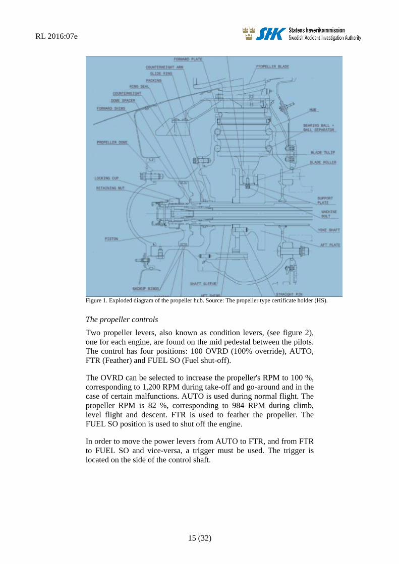
Figure 1. Exploded diagram of the propeller hub. Source: The propeller type certificate holder (HS).
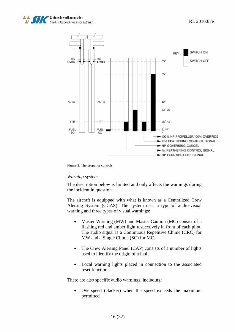
The propeller controls
Two propeller levers, also known as condition levers, (see figure 2),
one for each engine, are found on the mid pedestal between the pilots.
The control has four positions: 100 OVRD (100% override), AUTO,
FTR (Feather) and FUEL SO (Fuel shut-off).
The OVRD can be selected to increase the propeller's RPM to 100 %,
corresponding to 1,200 RPM during take-off and go-around and in the
case of certain malfunctions. AUTO is used during normal flight. The
propeller RPM is 82 %, corresponding to 984 RPM during climb,
level flight and descent. FTR is used to feather the propeller. The
FUEL SO position is used to shut off the engine.
In order to move the power levers from AUTO to FTR, and from FTR
to FUEL SO and vice-versa, a trigger must be used. The trigger is
located on the side of the control shaft.
RL 2016:07e
16 (32)
Figure 2. The propeller controls.
Warning system
The description below is limited and only affects the warnings during
the incident in question.
The aircraft is equipped with what is known as a Centralized Crew
Alerting System (CCAS). The system uses a type of audio-visual
warning and three types of visual warnings:
Master Warning (MW) and Master Caution (MC) consist of a
flashing red and amber light respectively in front of each pilot.
The audio signal is a Continuous Repetitive Chime (CRC) for
MW and a Single Chime (SC) for MC.
The Crew Alerting Panel (CAP) consists of a number of lights
used to identify the origin of a fault.
Local warning lights placed in connection to the associated
reset function.
There are also specific audio warnings, including:
Overspeed (clacker) when the speed exceeds the maximum
permitted.
RL 2016:07e
17 (32)
AP disconnection (cavalry charge) when the autopilot is
disconnected.
AC generator
Each engine is fitted with an AC generator used to power the electrical
de-icing systems for the propeller as well as other AC powered
electrical systems on the aircraft.
1.7 Meteorological information
According to SMHI's analysis: Wind 5-8 knots, visibility >10 km,
variable cloud mass with base at 1 500 – 1 800 feet, temperature /
dewpoint 0/-1 °C, QNH 1030 hPa.
1.8 Aids to navigation
Not applicable.
1.9 Communications
The crew communicated with the air traffic controller in the Visby
tower during the sequence of events, declared an emergency situation
and informed the tower that the right engine had been shut off.
1.10 Aerodrome information
Visby Airport is an approved instrument aerodrome. The airport had
operational status in accordance with the Swedish AIP14
.
1.11 Flight recorders
The aircraft was equipped with flight recorders that SHK has secured
for readout and analysis. The units have subsequently been returned to
the operator.
1.11.1 FDR15
The FDR was of the model FA2100 from L3 Communications with
the serial number 000550028. The unit is digital and can store data for
at least 25 hours.
The FDR was transported to SAAB AB in Linköping where data
readout was performed.
Binary data have then been converted by the French accident
authority, BEA, into engineering units by means of the French
manufacturer's parameter list. The converted data have then been
presented in the form of numerical values in table data and plots,
which are described in more detail in Section 1.16.5.
14 AIP – Aeronautical Information Publication. 15 FDR – Flight Data Recorder.
RL 2016:07e
18 (32)
1.11.2 Cockpit Voice Recorder (CVR16
)
The CVR was of the model FA2100 from L3 Communications with
the serial number 000547158. The unit is digital and has a recording
time of up to two hours.
The CVR was transported to SAAB AB where data readout took place
under the supervision of SHK's Investigator in Charge. Audio data
have then been transferred to a digital medium and transcribed.
The information from the voice recorder is found in section 1.1.2 in
the sections which concern the sequence of events and in section
1.16.6 in the parts concerning the background noise from CAM17
.
1.12 Site of incident and the aircraft after the incident
1.12.1 Site of incident
The incident occurred approximately 30 km north of Visby Airport at
an altitude of 7,000 feet.
1.12.2 The aircraft after the incident
Initially, the event was not considered to be a serious incident. Due to
this, the operator's maintenance organisation commenced fault
isolation and disassembled the right propeller. This work was
interrupted when SHK decided to investigate the incident.
The disassembly and investigation resumed when SHK and
representatives of BEA, UTAS18
and ATR19
were present.
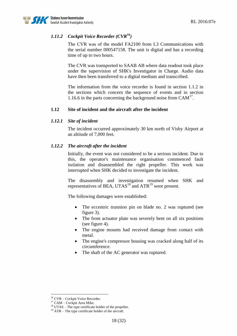
The following damages were established:
The eccentric trunnion pin on blade no. 2 was ruptured (see
figure 3).
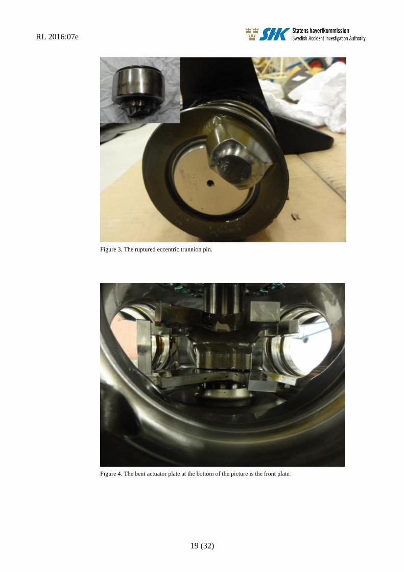
The front actuator plate was severely bent on all six positions
(see figure 4).
The engine mounts had received damage from contact with
metal.
The engine's compressor housing was cracked along half of its
circumference.
The shaft of the AC generator was ruptured.
16 CVR – Cockpit Voice Recorder. 17 CAM – Cockpit Area Mike. 18 UTAS – The type certificate holder of the propeller. 19 ATR – The type certificate holder of the aircraft.
RL 2016:07e
19 (32)
Figure 3. The ruptured eccentric trunnion pin.
Figure 4. The bent actuator plate at the bottom of the picture is the front plate.
RL 2016:07e
20 (32)
1.13 Medical information
Nothing indicates that the mental or physical condition of the pilots
were impaired before or during the flight.
1.14 Fire
There was no fire.
1.15 Survival aspects
1.15.1 Rescue operation
The airport's rescue services were alerted and prepared, but were not
required to perform any action as the landing was normal.
The ELT20
was not activated.
1.15.2 Position of and injury to those on board, and use of seat belts
Not applicable.
1.16 Tests and research
1.16.1 Propeller examination
After the initial investigation at the scene, the propeller was
disassembled and sent to the propeller production certificate holder's
facility in Figeac, France. The technical examination was performed
under the guidance and supervision of the French safety investigation
authority (BEA). Personnel from SHK were present.
In addition to the damages reported under 1.12.2 above, non-
destructive testing revealed that the other five trunnion pins had crack
indications on both sides.
The broken trunnion pin showed signs of multiple bilateral overloads.
The play of the bearings for the six trunnion pins was measured by
SHK and varied between 0.4 and 0.8 mm.
The ball bearings and the ball bearing separators from the blades
retentions were investigated by UTAS in the USA under the NTSB’s
supervision, where it was established, from a practical point of view,
that they were in airworthy condition.
1.16.2 Engine examination
The engine was examined by an authorised maintenance body under
BEA's supervision. The crack in the compressor housing was found to
have occurred as a result of the overloads produced by the propeller
during the event.
20 ELT – Emergency Locator Transmitter.
RL 2016:07e
21 (32)
1.16.3 Stress calculation of the actuator and trunnion pin
The manufacturer's FEM21
analysis reveals that the trunnion pin
reaches its tensile yield limit at 2,500-3,000 daN and that the front
actuator plate protuberances reaches this limit at 3,000 daN.
SHK's strength calculations have essentially shown identical values.
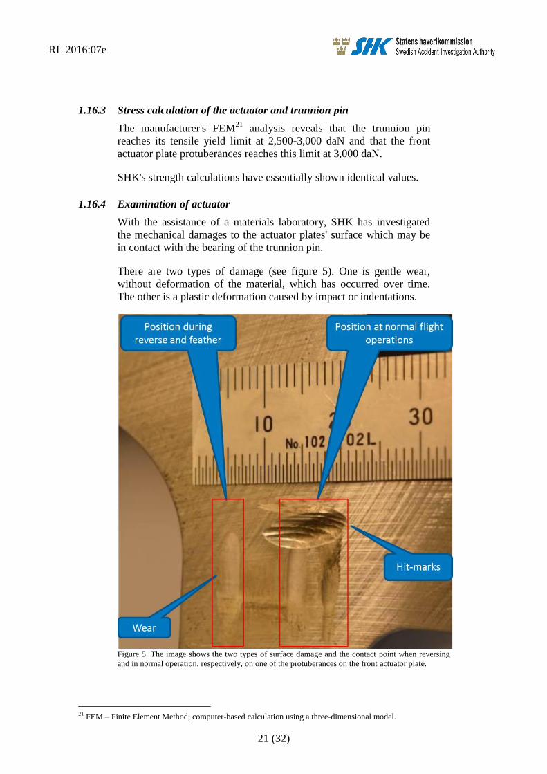
1.16.4 Examination of actuator
With the assistance of a materials laboratory, SHK has investigated
the mechanical damages to the actuator plates' surface which may be
in contact with the bearing of the trunnion pin.
There are two types of damage (see figure 5). One is gentle wear,
without deformation of the material, which has occurred over time.
The other is a plastic deformation caused by impact or indentations.
Figure 5. The image shows the two types of surface damage and the contact point when reversing
and in normal operation, respectively, on one of the protuberances on the front actuator plate.
21 FEM – Finite Element Method; computer-based calculation using a three-dimensional model.
RL 2016:07e
22 (32)
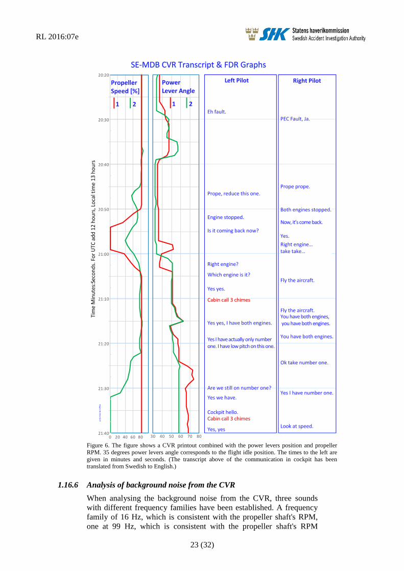
1.16.5 Analysis of FDR and CVR data
The FDR and CVR were removed from the aircraft and could be read.
The French investigation authority BEA assisted in the validation and
analysis of the data.
The analysis shows that the sequence of events commenced in
connection with the power levers being reduced to idle and the severe
vibrations beginning one minute and 20 seconds later. The indicated
air speed was between 241 and 254 kts during the sequence of events.
The timescale in figure 6 below begins three seconds before the severe
vibrations began.
RL 2016:07e
23 (32)
Figure 6. The figure shows a CVR printout combined with the power levers position and propeller
RPM. 35 degrees power levers angle corresponds to the flight idle position. The times to the left are
given in minutes and seconds. (The transcript above of the communication in cockpit has been
translated from Swedish to English.)
1.16.6 Analysis of background noise from the CVR
When analysing the background noise from the CVR, three sounds
with different frequency families have been established. A frequency
family of 16 Hz, which is consistent with the propeller shaft's RPM,
one at 99 Hz, which is consistent with the propeller shaft's RPM
Magnic
AB2016-03-07
RL 2016:07e
24 (32)
multiplied by six, and a frequency of 39 Hz from a source which could
not be identified.
The sound with the frequency of 99 Hz persists throughout. The
frequency of 16 Hz appeared when the power levers was pulled back
to idle at 12:19:03. The sound with the frequency of 39 Hz apperared
in conjunction with the severe vibrations commencing at 12:20:23 and
ceasing at 12:20:36. The vibrations and the sounds with frequencies
16 Hz and 39 Hz ceased when the right propeller was feathered.
1.16.7 Simulator tests
SHK has participated in simulator tests at the manufacturer in
Toulouse, France. The purpose of the tests was partly to investigate
the functionality of the propeller control and partly to gain general
knowledge of different methods of performing a descent.
The condition lever was manoeuvred from the AUTO position by
lifting the trigger and keeping it in its raised position whilst moving it
towards the FTR position. The lever then stopped a few millimetres
above the FTR position. The only means of moving on towards the
FTR position was to let the trigger drop back into position and pull the
control further back.
Descent was performed with varying rates of descent and speeds. The
manufacturer explained that a normal descent could be carried out
with either a rate of descent of 1,500 feet per minute or with a gradient
of three degrees and an indicated speed of 200, 220 or 240 kts.
1.16.8 The manufacturer's flight tests
Flight tests have been carried out, with equipment to allow the
measurement of forces on the trunnion pins, during different phases of
flight.
Data has been analysed and it has been established that at a speed
close to 250 kts and in flight idle, the forces on the trunnion pins are
low. Furthermore, the pins may have contact with either of the
actuator plates in this position.
1.17 Organisational and management information
Braathens Regional AB is a commercial aviation company that
principally operates passenger flights within Sweden.
The company has a valid operating certificate issued by the Swedish
Transport Agency.
RL 2016:07e
25 (32)
1.18 Additional information
1.18.1 Previous incidents of a similar nature
Six other incidents of a similar nature involving this aircraft type have
occurred between 2007 and 2014. Two of these are under
investigation by foreign safety investigation authorities. The others
have not been investigated by any authority, However they have been
adressed by the aircraft and propeller type certificate holders.
1.18.2 Incident involving SE-MDC
An investigator from SHK participated as an observer on a flight from
Bromma to Visby Airport. The flight was conducted with a sister
aircraft with registration SE-MDC. The purpose was to gain
knowledge of the flight operations environment in the cockpit.
Following take off from Bromma and during the climb to cruising
altitude, weak vibrations were detected, which produced deflections in
the form of movement to the left and right on both control wheels.
During descent to Visby, with the power levers on idle, the vibrations
increased in intensity when the speed approached 245 kts. At this
point, the vibrations could be felt in the feet and on the sidewall to the
door post. The vibrations ceased when the power levers were
increased slightly and the engines' torque (Tq) increased to a reading
in the region around 7-8 %.
The operator attempted to resolve the problem by performing a
dynamic balancing of the propellers. This was however unsuccessful.
The propeller blades were disassembled with the intention of
weighing them in order to check for a potential source of the fault. In
conjunction with this, a play in the trunnion pins' bearings was
discovered.
The bearings were replaced, after which the propellers could be
successfully balanced, meaning the vibrations did not return.
1.18.3 Basic principles for aeroelastic vibrations
All aircraft are flexible and change form as a result of the
aerodynamic forces caused by the flight. Long and slender aeroplane
wings are very flexible, and the lift created by the wings in order to
carry the weight of the aircraft produce relatively large deformations
during flight. The deformations of the wings change the aircraft's
shape, thereby changing the aerodynamic forces. This interaction is
known as aeroelasticity. The wings' deformations and movement
during flight can in different ways influence the aircraft's
manoeuvrability and flight safety.
If the deformation of the wings changes quickly, this aeroelastic
interaction becomes dynamic and the aircraft's distribution of mass
also affects the sequence of events via the inertial forces which arise.
RL 2016:07e
26 (32)
At a sufficiently high speed, this aeroelastic interaction between the
aircraft's elastic deformation, aerodynamic forces and inertial forces
becomes instable to the extent that fluctuations or vibrations become
instable and quickly increase in severity.
This form of aeroelastic instability is known as “flutter” and all
aircraft are investigated thoroughly in order to ensure flutter cannot
arise at the speeds at which the aircraft is intended to fly.
If the speed is high, it may be enough that a part of the aircraft's
structure is damaged, or breaks, for flutter or other aeroelastic
vibrations to occur. Certain serious types of faults are analysed when
the aircraft is designed, but far from all faults are investigated.
The aircraft's propellers and engines also work in unison with the
aircraft's other parts and make aeroelastic phenomena even more
complicated. Moving parts of the aircraft, such as control surfaces and
propellers, cannot be mounted without a certain amount of play. This
play can lead to aeroelastic vibrations which do not cause the aircraft
to come apart but which cause undesirable vibrations which can be
severe.
As aeroelastic phenomena are affected by the aircraft's rigidity, the
aerodynamic forces and the aircraft's mass distribution, this means that
every change in the aircraft's shape, rigidity or mass distribution can
affect the aircraft's aeroelastic properties. Small changes can also lead
to severe vibrations in the aircraft, which in turn can result in damage
or even an accident.
The manufacturer's investigation of the aircraft's aeroelastic qualities
has been limited to frequencies below 30 Hertz, which made it
difficult to establish the way in which the aircraft's aeroelastic
properties may have affected the sequence of events.
1.18.4 Actions taken
BEA
On 23 December 2014, BEA submitted four recommendations to
EASA concerning information on these problems to the operators.
EASA
On 30 January 2015, EASA published a safety information bulletin,
SIB No.: 2015-03 with information about the vibration problems.
EASA is capturing any new occurrence through an Airworthiness
Review Sheet (ARS 61.0003), in order to immediately launch the
proper measures to ensure the relevant hardware is secured.
On 19 January 2016, EASA revised the safety information bulletin,
SIB No.: 2015-3R1.
RL 2016:07e
27 (32)
The propeller's type certificate holder
The type certificate holder issued a service bulletin (568F-61-67,
dated 2 Oct 14) prior to the event in question, which included an
instructions for measuring the total amount of play in the actuator and
blade trunnion pin bearing mechanism interfaces. The intention with
the bulletin was to facilitate the detection of excessive backlash
caused by bent actuator plates following vibration incident in
combination with the indication of PEC fault codes 67 and 68 (sensed
blade angle fault, on the primary and secondary channels).
The type certificate holder is of the opinion that the damages to the
propeller mechanism occurred by means of the friction in the blades'
retention bearings becoming too high and that the force of the
hydraulic actuator caused the damages. The magnitude of the friction
increase results in high actuator pitch change forces applied to the blade
trunnion pins and actuator plates.
The vibrations which the crews reported are considered to be a result
of the blades achieving different angles depending on the deformation
in the mechanism.
Consistent with the propeller type certificate holder’s likely cause
theory, an improved ball bearing separator has been designed which is
being introduced to the propellers currently in operation and has been
incorporated in new production propellers.
The aircraft's type certificate holder
The aircraft's type certificate holder has published a bulletin (OEB –
Operations Engineering Bulletin) based on the current incident and
previous incidents. The purpose of the bulletin is to inform and
provide operators with recommendations for flight operations in terms
of events of sudden and severe vibrations on the engine installation
originating from mechanical damage to the propellers.
The bulletin explains that investigations have revealed that all
reported incidents occurred under the following circumstances:
On engine no. 2 (right engine)
During descent, at a speed of close to 250 kts
When the power levers (PL) were reduced to flight idle (FI)
The bulletin contains a procedure for identifying and shutting down
the affected engine.
1.19 Useful or effective investigation techniques
None.
RL 2016:07e
28 (32)
2. ANALYSIS
2.1 The flight
SHK has established that preparations and planning for the flight in
question followed normal procedures.
The formation of ice which occurred at cruising altitude is not
considered to have had an impact on the incident as the de-icing
system had the intended effect.
The crew attempted to rectify the problem with the initial vibrations
by manoeuvring the power levers; a measure which was based on
previous experience. However, the measure had no effect. SHK
considers it natural to use previous experience to solve a task,
especially when there is no published procedure for handling the
problem.
The commander decided to prioritise the flight – which was performed
using visual references – over reading through the checklists for
abnormal procedures. SHK considers this to be a correct prioritisation
as the level of vibrations was so high that there were difficulties
reading the instruments in the cockpit.
Clearer communication between the pilots, in terms of which power
levers was manoeuvred, would likely have contributed to solving the
task even quicker. The “PEC fault” warning, which indicated which
side the vibrations originated from, was not used as guidance for the
measures taken.
Initially, the right engine's propeller control could not be moved into
the shut-off position, which was likely caused by the trigger
unintentionally being in its upper position as the control reached the
feather position.
2.2 Damage to the propeller mechanism
The fracture surface of the ruptured blade trunnion pin reveals that
there have been multiple instances of overload, in both directions,
prior to the final rupture.
The damage to the actuator plates also shows evidence of multiple
instances of overload.
In figure 5, indentations from the support plate on the trunnion pin's
bearing is visible. These indentations have occurred as a result of the
protuberance of the actuator plate being bent. In the area for reversing,
there are no signs of contact with the washer, which shows that the
protuberance was not bent at the time of the previous landing. The
image also shows wear on the front actuator plate, which is evidence
that the trunnion pin bearing has had contact with it over time.
RL 2016:07e
29 (32)
The evidence above shows that the non-wear damage took place
during the incident flight.
As the crew did not perceive vibrations before the power levers were
reduced to flight idle, it is likely that all the non-wear damage
occurred after this reduction in power
It has not been possible to firmly establish the logic and the mechanics
behind the damages, but it cannot be ruled out that they may have
been a result of aeroelastic vibrations.
2.3 Damages to the engine, etc.
The damages to the engine and the engine mounts are deemed to have
been caused by the high level of vibrations that occurred during the
incident.
2.4 Measures taken by the propeller type certificate holder
As indicated previously, the propeller type certificate holder has
assessed that the likey cause of the incident was the development of
excessive friction in the blades' retention bearings. An improved ball
bearing separator has been designed and introduced as a correcting
action.
SHK establishes that the hydraulics can produce up to 12,000 daN at
the AFT plate and 10,300 daN on the forward plate. In order for the
actuator's forward protuberance to reach its tensile yield limit, a force
of 3,000 daN is required. This means that not all protuberances can
bend at the same time.
In order to achieve such damages via excessive friction in the blade
retention bearing, all of the following factors must occur, or already
be present, within the space of approximately one minute:
Uneven distribution of ball bearings and increased friction in
all six blade retentions.
The increased friction shall act in both directions.
A maximum of three blades may have higher friction at one
time.
The hydraulics must make around 20 movements in both
directions.
SHK does not consider it likely that this could happen within such a
short period of time.
2.5 Measures taken by the aircraft type certificate holder
The measures taken by the aircraft type certificate holder will likely
lead to pilots being able to identify and rectify severe propeller
vibrations in a more systematic way.
RL 2016:07e
30 (32)
2.6 Overall assessment
SHK is able to establish that the incident occurred during descent at
high speed when the power levers were reduced to idle and only the
right engine (engine no. 2) was affected. The investigations of similar
incidents carried out by other safety investigation authorities reveal
that they too occurred under similar circumstances. Via the measures
taken by BEA, EASA and the aircraft type certificate holder, the
operators of the aircraft type have been informed of this and a
procedure has been developed for identifying and shutting off the
affected engine in similar situations.
SHK does not share the propeller type certificate holder's opinion on
what caused the incident. According to SHK, it is not likely that the
measures taken by the propeller type certificate holder are such that
they sufficiently prevent the occurrence of a similar incident.
SHK's opinion is that further extensive engineering work in the form
of thorough calculations and tests is required to find the cause of the
incident.
The motive for this includes matters such as the registered and
unidentified frequency of 39 Hz. It has also been established that the
trunnion pins' bearing may be in contact with the front actuator plate
during normal operation.
The propeller type certificate holder has indicated that the trunnion pin
bearing by design should typically be against the aft plate protuberances
during normal operation.
The forward plate should normally be loaded during isolated operating
conditions, such as reverse operation.
The propeller type certificate holder has explained that the wear observed
on the forward actuator plate protuberances is due to increased friction in
the retention bearings.
SHK has established that both the aircraft type and propeller type have
undergone a number of small changes since their original certification.
There is nothing to suggest that any particular change has constituted
the cause of the accident. It would however be valuable to investigate
in greater detail whether the combined effect of the changes which
have been made are such that they have a negative impact on the
aircraft type's properties.
SHK considers such further investigative measures to be the
responsibility of the aircraft and propeller type certificate holders,
under supervision of the certifying authorities.
RL 2016:07e
31 (32)
2.7 Flight safety assessment
SHK has assessed the event as a serious incident, which means that
there was a high probability that an accident would occur.
The motive for this conclusion is that the resulting damages were of
such a nature that they could have developed into structural damages
in the engine installation. The fact that the incident occurred under
visual weather conditions has likely allowed for control of the aircraft
to be maintained despite the pilots' difficulties reading the instruments.
3. CONCLUSIONS
3.1 Findings
a) The crew was qualified to conduct the flight.
b) The aircraft had Certificate of Airworthiness and valid ARC.
c) The planning of the flight and the operation were normal until
the incident occurred.
d) There was no specific procedure for handling engine
vibrations.
e) The sequence starting with the vibrations and ending in the
feathering of the propeller lasted just over a minute.
f) Six similar incidents have occurred, two of which are under
investigation by foreign safety investigation authorities.
g) The mechanisms that caused the propeller damage could not
be established.
h) Information on the situations in which similar incidents can
occur and how they should be handled has been
communicated to the concerned operators.
3.2 Causes of the serious incident
SHK has been unable to establish the cause of the serious incident.
RL 2016:07e
32 (32)
4. SAFETY RECOMMENDATIONS
SHK's assessment is that additional extensive engineering initiatives
are necessary in order to find the cause of the incident and that such
initiatives should be the responsibility of the aircraft and propeller
type certificate holders, under supervision of the certifying authorities.
It has also been possible to establish that the known incidents of a
similar nature have taken place under similar circumstances. In light
of this, the following recommendation is issued.
EASA is recommended to:
Consider introducing temporary limitations in the manoeuvring
envelope, or limitations of the power ranges within the latter, until
the problem is resolved and rectified. (RL 2016:07 R1)
SHK respectfully requests to receive, by 20 January 2017 at the latest,
inshapeation regarding measures taken in response to the safety
recommendations included in this report.
On behalf of the Swedish Accident Investigation Authority,
Jonas Bäckstrand Sakari Havbrandt
Appendices
Submission to the final report by BEA (The French authority for safety
investigations in the filed of civil aviation).