final report project title: dial’a’whip
TRANSCRIPT
EEL 4924 Electrical Engineering Design
(Senior Design)
Final Report
25 April 2012
Project Title: Dial’A’Whip
Team Members:
Name: Chris Calvo
Name: Daniel De Leo
Project Abstract:
Dial’A’Whip consists of a compact module that connects to a car’s electrical system to allow partial
system control and relay status information about the car to the owner. The module will allow the owner
to use a cellphone to remotely perform several functions on the car such as: Lock/Unlock doors, open
trunk, read inside temperature, receive GPRS location, sense internal lights and external headlights,
receive door status, sense motion inside car, and start the car. The project presents the technical
challenge of interfacing a microcontroller with both a GSM modem and a car’s BCM (Body Control
Module). Once the project has been completed, it is expected that Dial’A’Whip will present users with
the ability to partially control their car and check on the status of their car using SMS text messages on
any cellphone.

University of Florida EEL 4924—Spring 2012 25-Apr-12 Electrical & Computer Engineering
Page 2/12 Final Report
Contents Introduction: .......................................................................................................................................... 3
Project Features: .................................................................................................................................... 4
Concept/Technology Selection: .............................................................................................................. 5
Visual of Functionality: ......................................................................................................................... 6
Installation: ............................................................................................................................................ 7
System Block Diagram: ......................................................................................................................... 8
Software Flowchart: ............................................................................................................................... 9
Android Application: ........................................................................................................................... 10
Distribution of Labor: .......................................................................................................................... 11
Project Costs: ....................................................................................................................................... 11
Grant Chart: ......................................................................................................................................... 12
Figures
Figure 1 – Dial’A’Whip Module ............................................................................................................ 3 Figure 2 – Android App ......................................................................................................................... 4
Figure 3 – Basic SMS Texting ............................................................................................................... 4 Figure 4 – Basic View of Software Function .......................................................................................... 6
Figure 5 - Module Connectors ................................................................................................................ 7 Figure 6 - Dial’A’Whip System Block Diagram ..................................................................................... 8
Figure 7 - Software Flowchart ................................................................................................................ 9 Figure 8 – Android App Home Screen ................................................................................................. 10
Figure 9 – Android App Extra Features Screen .................................................................................... 10 Figure 10 – Android GPS Car Locator Screen ...................................................................................... 10
Figure 11 – Grant Chart ....................................................................................................................... 12
University of Florida EEL 4924—Spring 2012 25-Apr-12 Electrical & Computer Engineering
Page 3/12 Final Report
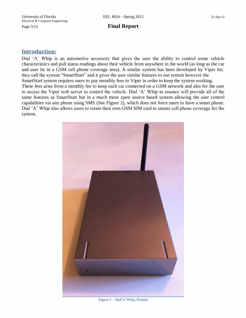
Introduction: Dial ‘A’ Whip is an automotive accessory that gives the user the ability to control some vehicle
characteristics and pull status readings about their vehicle from anywhere in the world (as long as the car
and user lie in a GSM cell phone coverage area). A similar system has been developed by Viper Inc.
they call the system “SmartStart” and it gives the user similar features to our system however the
SmartStart system requires users to pay monthly fees to Viper in order to keep the system working.
These fees arise from a monthly fee to keep each car connected on a GSM network and also for the user
to access the Viper web server to control the vehicle. Dial ‘A’ Whip in essence will provide all of the
same features as SmartStart but in a much more open source based system allowing the user control
capabilities via any phone using SMS (See Figure 2), which does not force users to have a smart phone.
Dial ‘A’ Whip also allows users to retain their own GSM SIM card to ensure cell phone coverage for the
system.
Figure 1 – Dial’A’Whip Module

University of Florida EEL 4924—Spring 2012 25-Apr-12 Electrical & Computer Engineering
Page 4/12 Final Report
Project Features: • Plug and Play
– Module plugs directly into OBDII port
• Internal Battery Back-up
– Uninterruptable power supply to system
• Internal Temperature Sensing
– Module able to SMS text the user the temperature inside the car.
• Internal Motion Sensor
– Module alerts the user via SMS text whenever motion is sensed inside the car
• Interface With Installed BCM/Remote Starter
– Module connects to BCM through CAN BUS to allow the following features:
• Car Status
• Lock/Unlock Door Control
• Trunk Opening Control
• Remote Engine Start
• SMS Security
– 4 digit passcode required for all text commands
• Android Mobile Application (See Figure 1)
– Ability to interact with the car module using a graphical interface rather than simple SMS
texts. The application presents the user with buttons which send the corresponding
commands automatically via SMS, saving the user the extra effort of composing texts.
Figure 2 – Android App
Figure 3 – Basic SMS Texting
University of Florida EEL 4924—Spring 2012 25-Apr-12 Electrical & Computer Engineering
Page 5/12 Final Report
Concept/Technology Selection:
Dial’A’Whip is broken down into three main parts that together fulfill the objectives of providing users
control of their car from anywhere in the world:
1. The communication backbone to the Dial’A’Whip system in order to provide nearly worldwide
coverage for our system we opted to use the widely used GSM technology (cell phone
architecture). By using GSM the Dial’A’Whip system is always accessible to the user as long as
the user is within range of a cell phone tower and the system is as well.
Another benefit of using GSM versus other cell phone architectures is the fact that with GSM
SIM cards are required in order to access the network this gives consumers of the Dial’A’Whip
system the ability to choose any GSM carrier/provider that they wish. Other possibilities that
were examined included WIFI and Bluetooth however both of these technologies did not provide
the coverage we were looking for to provide a nearly worldwide coverage for the Dial’A’Whip
system.
2. The processing power and overall control center for the Dial’A’Whip system will be placed on
the shoulders of an Atmel Atmega 2560 microcontroller. This microcontroller provides us with
access to UART connections that are full duplex (can send and receive simultaneously), which is
essential to our application considering communication with the GSM modem is done
completely through UART.
Another feature of this microcontroller is its large flash memory which totals up to 256 KB this
allows for plenty of room to design a robust system all on one chip without the need for external
memory interface. Lastly, because this microcontroller is widely used in industry there is access
to a lot of example code and literature that will all help to realize the Dial’A’Whip control center.
A few other microcontrollers were examined (PIC, TI, and other Atmel chips) however they all
lacked one or all of the above key features that the Atmega 2560 offered.

University of Florida EEL 4924—Spring 2012 25-Apr-12 Electrical & Computer Engineering
Page 6/12 Final Report
3. Interfacing with the vehicle is done via the CAN BUS interface which is standard on all cars
manufactured in 2006 and later. The Dial’A’Whip system has an on-board MCP2515 and
MCP2551 which are the controller and transceiver in charge of CAN BUS communication. It is
this CAN BUS communication which allows the Dial’A’Whip system to be completely plug and
play via the OBDII port on any car.
Visual of Functionality:
Figure 4 – Basic View of Software Function

University of Florida EEL 4924—Spring 2012 25-Apr-12 Electrical & Computer Engineering
Page 7/12 Final Report
Installation:
Dial’A’Whip has two simple connections that are used to install the module on the car. Two cables are
used. One cable has a DB-9 serial connector on one side which plugs into the back of the system to the
DB-9 port (shown below). The other side of the cable has an OBDII connector which plugs into the
car’s OBDII port below the steering wheel. The second cable has the motion sensor on one end and a
USB connector on the other. The USB connector plugs into the side USB port of the Dial’A’Whip
system (shown below). Those two cables are all that are necessary to install the system. When the power
switch is turned on, the system boots and within seconds is ready to receive texts.
Figure 5 - Module Connectors
University of Florida EEL 4924—Spring 2012 25-Apr-12 Electrical & Computer Engineering
Page 8/12 Final Report
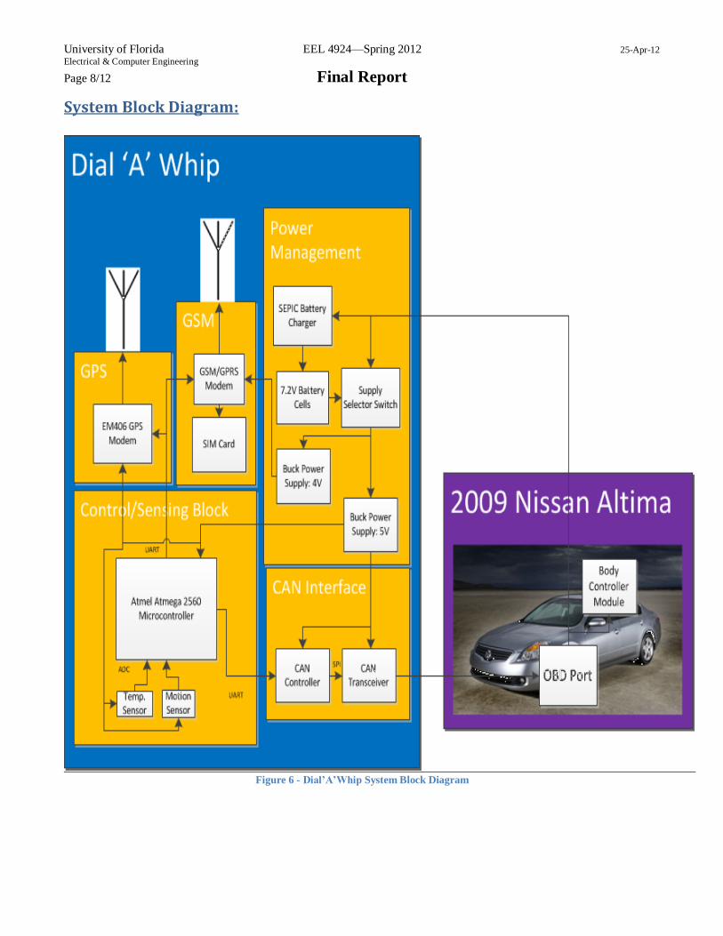
System Block Diagram:
Figure 6 - Dial’A’Whip System Block Diagram

University of Florida EEL 4924—Spring 2012 25-Apr-12 Electrical & Computer Engineering
Page 9/12 Final Report
Software Flowchart:
Figure 7 - Software Flowchart
University of Florida EEL 4924—Spring 2012 25-Apr-12 Electrical & Computer Engineering
Page 10/12 Final Report
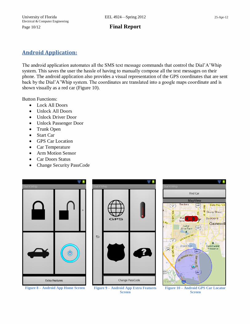
Android Application:
The android application automates all the SMS text message commands that control the Dial’A’Whip
system. This saves the user the hassle of having to manually compose all the text messages on their
phone. The android application also provides a visual representation of the GPS coordinates that are sent
back by the Dial’A’Whip system. The coordinates are translated into a google maps coordinate and is
shown visually as a red car (Figure 10).
Button Functions:
Lock All Doors
Unlock All Doors
Unlock Driver Door
Unlock Passenger Door
Trunk Open
Start Car
GPS Car Location
Car Temperature
Arm Motion Sensor
Car Doors Status
Change Security PassCode
Figure 8 – Android App Home Screen
Figure 9 – Android App Extra Features
Screen
Figure 10 – Android GPS Car Locator
Screen

University of Florida EEL 4924—Spring 2012 25-Apr-12 Electrical & Computer Engineering
Page 11/12 Final Report
Distribution of Labor: The following is a breakdown of each team member's projected labor by approximate percentage.
Christopher Calvo Daniel De Leo
Preliminary Research 50% 50%
Design Phase 50% 50%
Board Construction 90% 10%
Interfacing With Car 80% 20%
C code for Atmel 20% 80%
Test and Debug 50% 50%
Physical Assembly 50% 50%
Android App Development 10% 90%
Project Costs: GSM Module $60.00
GPS Module $60.00
Temperature Sensor $1.50
Motion Sensor $10.00
Connectors/Cables $20.00
PCB $33.00
ATMEGA2560 w/ Oscillators $22.00
Capacitors, Resistors, Inductors $8.00
ICs $12.50
Total $227

University of Florida EEL 4924—Spring 2012 25-Apr-12 Electrical & Computer Engineering
Page 12/12 Final Report
Grant Chart:
Figure 11 – Grant Chart