final report of the preparatory s on the project
TRANSCRIPT
Ministry of Planning and International Cooperation The Repiblic of Yemen
FINAL REPORT OF THE PREPARATORY SURVEY
ON THE PROJECT FOR
INTRODUCTION OF CLEAN ENERGY BY SOLAR ELECTRICITY GENERATION SYSTEM
IN THE REPUBLIC OF YEMEN
August 2010
JAPAN INTERNATIONAL COOPERATION AGENCY
NEWJEC Inc. JAPAN TECHNO Co., LTD. I D D
J R
10-075
PREFACE
Japan International Cooperation Agency (JICA) decided to conduct the preparatory survey on THE
PROJECT FOR INTRODUCTION OF CLEAN ENERGY BY SOLAR ELECTRICITY GENERATION
SYSTEM in Republic of Yemen.
JICA sent to Yemen survey team headed by Mr. Masaru NISHIDA of NEWJEC Inc. and consist of
NEWJWC Inc. and JAPAN TECHNO CO., LTD. from 11/7 to 23/7 and from 4/10 to 22/10, 2009.
The team held discussions with the officials concerned of the Government of Yemen, and conducted a
field study at the study area. After the team returned to Japan, further studies were made. Then, a mission
was sent to Yemen in order to discuss a draft outline design, and as this result, the present report was
finalized.
I hope that this report will contribute to the promotion of the project and to the enhancement of friendly
relations between our two countries.
Finally, I wish to express my sincere appreciation to the officials concerned of the
Government of Republic of Yemen for their close cooperation extended to the teams.
August 2010
Kazuhiro YONEDA
Director General,
Industrial Development
Japan International Cooperation Agency

SUMMARY
Final Report on the Preparatory Survey on the Project for Introduction of Clean Energy by Solar Electricity Generation System in the Republic of Yemen Summary
- 1 -
Summary
I. Outline of the Recipient County
The Republic of Yemen is located in the southern end of the Arabia Peninsula, stretching 12 to 19 degrees latitude north, 43 to 54 degrees longitude north. Out of its territory of 555 thousand sq- km, 5.5% is forest and 34% agricultural land. Aden City is a port town facing the Gulf of Aden, with annual average temperature 29 degrees Celsius, and annual rainfall of 32mm is observed in two separate wet seasons (December to January and July), and the highest temperature reaches 40degrees in summer.
Yemen is classified as one of the least developed countries falling behind other Middle East countries. Gross National Product (GNP) per capital is US$965 (Central Statistics Office, 2007), the large proportion (approximately 30%) of which is generated by export of oil product, 90% of total export, started in 1980s. Between 2004 and 2007 GNP grew at 14.1% per annum, mostly due to world-wide hike of petroleum product prices and commodity prices in general. The reserve of oil is somewhat limited and the production has slowed down. Meanwhile, natural gas was found recently and exportation of LNG was started in 2009, as well as the use in a gas-turbine power plant.
The components of GNP are; agro-fishery 10%, manufacturing 10%, power and water 0.7%, distribution 16.4%, transport/communication 11.7%, finance and real estates 10.5%, and public sector 10%. Manufacturing and distribution have been expanding, while agro-fishery and mining including oil contracting.
Yemen has been making efforts to open up its economy, by joining Gulf Cooperation Council (GCC) and promoting economic fusion with other Arabic countries. The Government is also trying more stringent management of external debts and foreign reserves to prepare for the globalization of world economy. Further it is intending to develop its economy through liberalization of external trade, promotion of export, and inviting more FDI.
II. Background of the Project and its Outline
More than 50% of power production in Yemen comes from steam turbine power plants burning fuel oil, and the rest from diesel engine power plants. Thus the country is completely dependent on fossil fuel for its primary energy of electricity. The country is trying to shift the primary energy to natural gas from oil of which the reserve is limited. Use of renewable energy including solar power for rural electrification is being called for, and the Government has turned to introducing clean energy.
Renewable Energy Strategy and Action Plan published in June 2008 aims at realizing provision of power in rural areas, not reached by Public Power Corporation's transmission expansion plans, by off-grid sources such as solar energy and wind power/diesel hybrid. In April 2009, the Government
Final Report on the Preparatory Survey on the Project for Introduction of Summary Clean Energy by Solar Electricity Generation System in the Republic of Yemen
- 2 -
issued a republic law to establish the public rural electrification agency, which is given a task to study appropriate and cost effective methods of electricity provision including new-energy and renewable energy, and to select suitable methods that meet the needs and demand in rural areas.
The country decided to join "Cool Earth Partnership" and takes up as its policy priority reduction of GHGs emission and promotion of economic development, by the approach of adaptation and mitigation to climate change. In accordance with the initiative, Yemeni Government requested to the Government of Japan for Grant Aid in June 2009.
Having received this request, JICA conducted the first phase site survey between July 11th to 22nd in 2009, identified Sabaeen Hospital in the capital Sana'a and Al Wahda Hospital in Aden as candidate sites, and made into an agreement with the Recipient.
III. Outline of Study Result and the Content of the Project
Based on the results of the first phase study, the scale and efficiency of both site candidates have been reviewed in Japan, and Al Wahda Hospital was chosen as the Project Site. Subsequently JICA sent the Study Team for the second phase site survey between October 4th and 23rd to Yemen, to investigate the Site, collect related information and have discussion with the Recipient concerning the contents of the Project.
After coming back to Japan, the Study Team examined the necessity, effectiveness and appropriateness of the Project on the basis of the result of the site survey, and prepared a Basic Design Report. With the Basic Design Report in hand, JICA's Study Team visited Yemen again between April 10th and 16th 2010, explained and discussed the report, and signed the minute of meeting with the Government of Yemen.
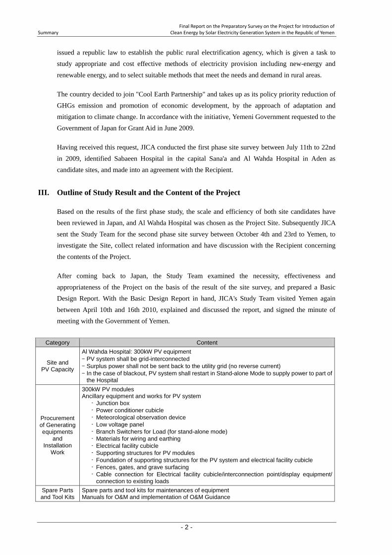
Category Content
Site and PV Capacity
Al Wahda Hospital: 300kW PV equipment - PV system shall be grid-interconnected - Surplus power shall not be sent back to the utility grid (no reverse current) - In the case of blackout, PV system shall restart in Stand-alone Mode to supply power to part of
the Hospital
Procurement of Generating equipments
and Installation
Work
300kW PV modules Ancillary equipment and works for PV system
- Junction box - Power conditioner cubicle - Meteorological observation device - Low voltage panel - Branch Switchers for Load (for stand-alone mode) - Materials for wiring and earthing - Electrical facility cubicle - Supporting structures for PV modules - Foundation of supporting structures for the PV system and electrical facility cubicle - Fences, gates, and grave surfacing - Cable connection for Electrical facility cubicle/interconnection point/display equipment/
connection to existing loads Spare Parts and Tool Kits
Spare parts and tool kits for maintenances of equipment Manuals for O&M and implementation of O&M Guidance
Final Report on the Preparatory Survey on the Project for Introduction of Clean Energy by Solar Electricity Generation System in the Republic of Yemen Summary
- 3 -
The Project proposed is to provide Al Wahda Hospital with a photovoltaic system (PV system) of 300kW peak power and to supply electric power to the facility, as well as to give training programs covering topics like methods of operation and maintenance, and planning of solar power projects. The Responsible Organization is the Ministry of Planning and International Cooperation, and the implementing agency the Ministry of Public Health and Population. The outline of basic design of the PV equipment is shown in the table below.
IV. Project Implementation Cost and Period
The cost of this Project implemented under Japan's Grand Aid scheme includes expenses on Yemeni side approximately YR 3.7million for travel cost of participants to training programs.
The project period is planned to be five months for tendering stage, and fourteen months for the procurement of the Products and their installation.
V. Evaluation of the Project
The generating equipment procured in the Project is designed to be managed by the Site, Al Wahda Hospital, for its daily operation and maintenance, with supervision of the Ministry of Public Health and Population. The management of the equipment in the long run will also require technical assistance and input from the Ministry of Electricity and Energy.
At the implementation stage of the Project, a series of the training programs will be provided for operation and maintenance techniques and knowledge on solar generation and its planning and use. The training programs is planned with intentions to make effective and sustainable the operation and maintenance organization mentioned above, and to contribute to the promotion of solar energy use in Yemen.
The direct effect of this Project is expected to be the introduction of renewable energy source in Yemen which is dependent on fossil fuel for the primary energy of electricity, reducing fossil fuel consumption and the emission of the main cause of climate change, CO2. The study estimates that the expected reduction in CO2 emission due to the Project is 258 t-CO2 per year.
This Project will install the largest-scale solar generation system in Yemen with its population distributed over the territory and in need of solar energy in electrification of rural areas. The Project is expected to demonstrate the effectiveness of solar energy use to the wider public of the country, and will contribute to the promotion of its use in private sector.
Meanwhile, PV modules and power conditioners made by Japanese manufacturers have technical advantages over other countries in their efficiency, longevity, reliability, etc. in the market. As this Project is limiting the country of origin of this equipment to Japan, the Project will be able to offer advanced technology of Japanese products.

Final Report on the Preparatory Survey on the Project for Introduction of Summary Clean Energy by Solar Electricity Generation System in the Republic of Yemen
- 4 -
Adding up the discussions above, it is concluded that the Project planned herein is very effective and appropriate as a project implemented as Programme Grant Aid for Environment and Climate Change.
Final Report on the Preparatory Survey on the Project for Introduction of Clean Energy by Solar Electricity Generation System in the Republic of Yemen Table of Contents
- i -
Table of Contents Preface Summary Contents Location Map List of Figures and Tables Abbreviation
Chapter 1 Background of Project .......................................................................................... 1 - 1 1-1 Background of the Study ......................................................................................................... 1 - 1 1-2 Project Site and Surroundings ................................................................................................. 1 - 3
1-2-1 Related Infrastructure ................................................................................................ 1 - 3 1-2-2 Natural Condition ...................................................................................................... 1 - 5 1-2-3 Environmental and Social Considerations ................................................................. 1 - 7
1-3 Global Issues ........................................................................................................................... 1 - 10
Chapter 2 Contents of the Project ......................................................................................... 2 - 1 2-1 Outline of the Project .............................................................................................................. 2 - 1 2-2 Basic Design of the Project ..................................................................................................... 2 - 2
2-2-1 Design Policy ............................................................................................................ 2 - 2 2-2-1-1 Design of the System .................................................................................. 2 - 2 2-2-1-2 Natural Condition ....................................................................................... 2 - 3 2-2-1-3 Local Conditions affecting the Works ........................................................ 2 - 4 2-2-1-4 Application of Local Resource ................................................................... 2 - 4 2-2-1-5 Capability of Operation and Maintenance .................................................. 2 - 5 2-2-1-6 Schedule of Procurement and Installation .................................................. 2 - 6
2-2-2 Basic Plan (Construction Plan/Equipment Plan) ....................................................... 2 - 6 2-2-2-1 Design Condition ........................................................................................ 2 - 6 2-2-2-2 Layout Plan of the PV System .................................................................... 2 - 7 2-2-5-3 Outline of Basic Design ............................................................................. 2 - 7 2-2-2-4 Outline of Equipment Plan ......................................................................... 2 - 8
2-2-3 General Drawing ....................................................................................................... 2 - 25 2-2-4 Implementation Plan.................................................................................................. 2 - 26
2-2-4-1 Implementation Policy / Procurement Policy ............................................. 2 - 26 2-2-4-2 Procurement/Installation Conditions .......................................................... 2 - 28 2-2-4-3 Scope of Work ............................................................................................ 2 - 28 2-2-4-4 Consultant Supervision ............................................................................... 2 - 30 2-2-4-5 Quality Control Plan ................................................................................... 2 - 32 2-2-4-6 Procurement Plan ....................................................................................... 2 - 32 2-2-4-7 Operational Guidance Plan ......................................................................... 2 - 32 2-2-4-8 Proposal on Training Program .................................................................... 2 - 34 2-2-4-9 Implementation Schedule ........................................................................... 2 - 43
2-3 Obligations of Recipient Country ........................................................................................... 2 - 44 2-4 Project Operation Plan ............................................................................................................ 2 - 45
2-4-1 Basic Concept of Operation and Maintenance of Generating Equipment ................. 2 - 45
Final Report on the Preparatory Survey on the Project for Introduction of Table of Contents Clean Energy by Solar Electricity Generation System in the Republic of Yemen
- ii -
2-4-2 Periodical Inspection ................................................................................................. 2 - 46 2-4-3 Long term Operation and Maintenance ..................................................................... 2 - 47 2-4-4 Spare Parts ................................................................................................................. 2 - 48
2-5 Cost Estimation of Project ...................................................................................................... 2 - 50 2-5-1 Cost of Procurement of Products and Services ......................................................... 2 - 50 2-5-2 Cost of Operation and Maintenance .......................................................................... 2 - 51
2-6 Other Relevant Issues ............................................................................................................. 2 - 54
Chapter 3 Project Evaluation and Recommendations .......................................................... 3 - 1 3-1 Recommendations ................................................................................................................... 3 - 1
3-1-1 Prerequisite to Project Implementation ..................................................................... 3 - 1 3-1-2 External Conditions to Achievement of Project Objectives ...................................... 3 - 1
3-2 Project Evaluation ................................................................................................................... 3 - 3 3-2-1 Validity of the Project ................................................................................................ 3 - 3 3-2-2 Effectiveness of the Project ....................................................................................... 3 - 4
[Drawings] [Appendices] 1. Member List of the Study Team
2. Study Schedule 3. List of Parties Concerned in the Recipient Country 4. Minutes of Discussions 5. Soft Component (Technical Assistance) Plan 6. References
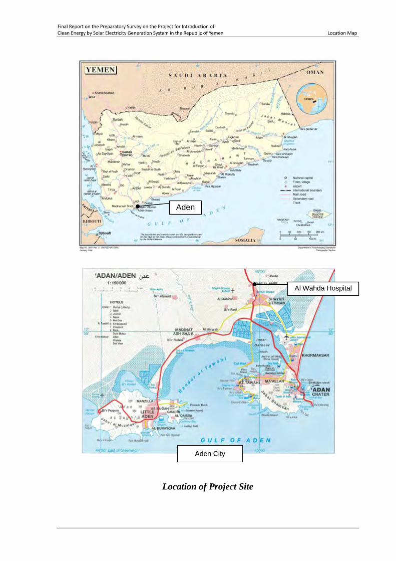
Final Report on the Preparatory Survey on the Project for Introduction of Clean Energy by Solar Electricity Generation System in the Republic of Yemen Location Map
Location of Project Site
Aden City
Al Wahda Hospital
Aden
Final Report on the Preparatory Survey on the Project for Introduction of Clean Energy by Solar Electricity Generation System in the Republic of Yemen List of Figures & Tables
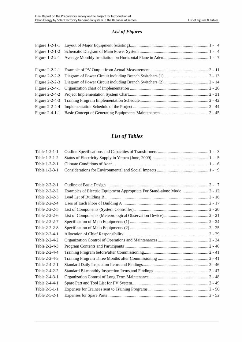
List of Figures
Figure 1-2-1-1 Layout of Major Equipment (existing) ......................................................................... 1 - 4 Figure 1-2-1-2 Schematic Diagram of Main Power System ................................................................ 1 - 4 Figure 1-2-2-1 Average Monthly Irradiation on Horizontal Plane in Aden .......................................... 1 - 7 Figure 2-2-2-1 Example of PV Output from Actual Measurement ...................................................... 2 - 11 Figure 2-2-2-2 Diagram of Power Circuit including Branch Switchers (1) ......................................... 2 - 13 Figure 2-2-2-3 Diagram of Power Circuit including Branch Switchers (2) ......................................... 2 - 14 Figure 2-2-4-1 Organization chart of Implementation ......................................................................... 2 - 26 Figure 2-2-4-2 Project Implementation System Chart .......................................................................... 2 - 31 Figure 2-2-4-3 Training Program Implementation Schedule................................................................ 2 - 42 Figure 2-2-4-4 Implementation Schedule of the Project ...................................................................... 2 - 44 Figure 2-4-1-1 Basic Concept of Generating Equipments Maintenances ............................................ 2 - 45
List of Tables
Table 1-2-1-1 Outline Specifications and Capacities of Transformers ............................................... 1 - 3 Table 1-2-1-2 Status of Electricity Supply in Yemen (June, 2009) ..................................................... 1 - 5 Table 1-2-2-1 Climate Conditions of Aden ......................................................................................... 1 - 6 Table 1-2-3-1 Considerations for Environmental and Social Impacts ................................................ 1 - 9
Table 2-2-2-1 Outline of Basic Design ............................................................................................... 2 - 7 Table 2-2-2-2 Examples of Electric Equipment Appropriate For Stand-alone Mode ......................... 2 - 12 Table 2-2-2-3 Load Lst of Building B ................................................................................................ 2 - 16 Table 2-2-2-4 Uses of Each Floor of Building A ................................................................................ 2 - 17 Table 2-2-2-5 List of Components (System Controller) ..................................................................... 2 - 20 Table 2-2-2-6 List of Components (Meteorological Observation Device) ......................................... 2 - 21 Table 2-2-2-7 Specification of Main Equipments (1) ......................................................................... 2 - 24 Table 2-2-2-8 Specification of Main Equipments (2) ......................................................................... 2 - 25 Table 2-2-4-1 Allocation of Chief Responsibility ............................................................................... 2 - 29 Table 2-2-4-2 Organization Control of Operations and Maintenances ............................................... 2 - 34 Table 2-2-4-3 Program Contents and Participants .............................................................................. 2 - 40 Table 2-2-4-4 Training Program before/after Commissioning ............................................................ 2 - 41 Table 2-2-4-5 Training Program Three Months after Commissioning ............................................... 2 - 41 Table 2-4-2-1 Standard Daily Inspection Items and Findings............................................................. 2 - 46 Table 2-4-2-2 Standard Bi-monthly Inspection Items and Findings ................................................... 2 - 47 Table 2-4-3-1 Organization Control of Long Term Maintenance ....................................................... 2 - 48 Table 2-4-4-1 Spare Part and Tool List for PV System ....................................................................... 2 - 49 Table 2-5-1-1 Expenses for Trainees sent to Training Programs ........................................................ 2 - 50 Table 2-5-2-1 Expenses for Spare Parts .............................................................................................. 2 - 52
Final Report on the Preparatory Survey on the Project for Introduction of Clean Energy by Solar Electricity Generation System in the Republic of Yemen Abbreviations
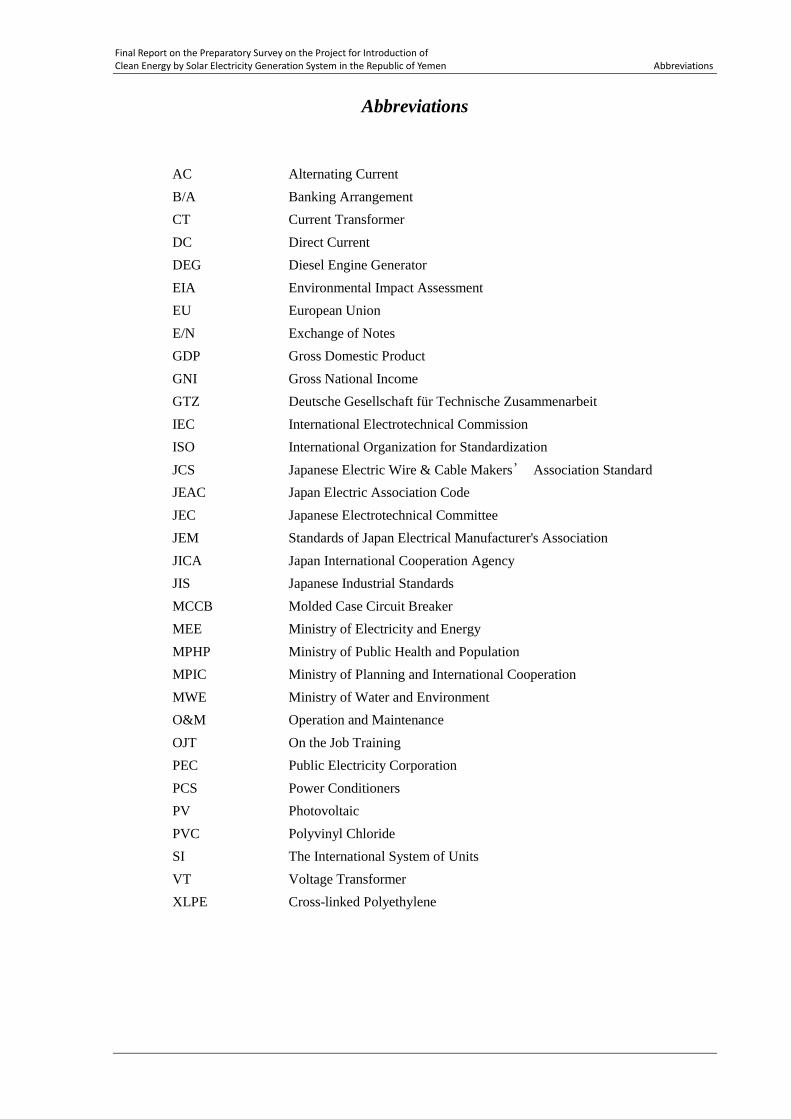
Abbreviations
AC Alternating Current B/A Banking Arrangement CT Current Transformer DC Direct Current DEG Diesel Engine Generator EIA Environmental Impact Assessment EU European Union E/N Exchange of Notes GDP Gross Domestic Product GNI Gross National Income GTZ Deutsche Gesellschaft für Technische Zusammenarbeit IEC International Electrotechnical Commission ISO International Organization for Standardization JCS Japanese Electric Wire & Cable Makers’ Association Standard JEAC Japan Electric Association Code JEC Japanese Electrotechnical Committee JEM Standards of Japan Electrical Manufacturer's Association JICA Japan International Cooperation Agency JIS Japanese Industrial Standards MCCB Molded Case Circuit Breaker MEE Ministry of Electricity and Energy MPHP Ministry of Public Health and Population MPIC Ministry of Planning and International Cooperation MWE Ministry of Water and Environment O&M Operation and Maintenance OJT On the Job Training PEC Public Electricity Corporation PCS Power Conditioners PV Photovoltaic PVC Polyvinyl Chloride SI The International System of Units VT Voltage Transformer XLPE Cross-linked Polyethylene

CHAPTER 1 BACKGROUND OF PROJECT
Final Report on the Preparatory Survey on the Project for Introduction of Chapter 1 Clean Energy by Solar Electricity Generation System in the Republic of Yemen Background of Project
1 - 1
Chapter 1 Background of Project
1-1 Background of the Study
Yemn has a chronic problem of shortage of generation capacity. Facilities of generation, power transmission, and power distribution are aging, and renewal or capacity enhancement of those facilities has not been catching up with the growth of demand. Due to the delay of network expansion, independent generation facilities have increased in regions, and expensive fuel is being consumed in less efficient manner. Japanese government announced its policy initiative in Davos in January 2008 to assist developing countries which intend to contribute to mitigation of climate change by means of reduction of greenhouse gas emission without compromising their economic development. The initiative is called "cool earth partnership" and aims to support developing countries in their efforts to reduce energy consumption and emissions, and also to adapt to the change in climate. As one of measures, Japanese government set up "Programme Grant Aid for Environment and Climate Change ", a financial mechanism to support member countries which have difficulties in executing capabilities and funding. Using this measure, Japanese government is seeking opportunities to employ its advanced technology of photovoltaics as a clean energy source in international cooperation. Ministry of Foreign Affairs of Japan has conducted needs surveys for Program Grant Aid for Environment and Climate Change using photovoltaic technology among member countries of Cool Earth Partnership, and Yemen Government responded with its candidate projects. Requested Components for this Grant Aid project submitted in June 2009 is as follows. Amount of request: US$5,000,000 Description of request: Arrangement of solar systems for following institutions.
a) Sabaeen Hospital Location: Al Sabaeen Plaza in center of Sana'a City, b) Al Wahda Hospital Location: Al Sheikh Otham district in Aden City c) Al Thawra Hospital Location: Al Thawra Street in Taizz City
Equipment and materials requested
a) Junction Box
Chapter 1 Final Report on the Preparatory Survey on the Project for Introduction of Background of Project Clean Energy by Solar Electricity Generation System in the Republic of Yemen
1 - 2
b) Power conditioner c) Circuit Breaker d) Solar module e) Cables f) Equipment for data collection and display
Soft component (technical assistance) requested
a) Workshop for maintenance and management of operation Target: Technicians of PEC Period: Two weeks b) Technical training for maintenance and management of operation Target: Senior technicians of PEC Period: One month c) Preparation of manual for maintenance and management of operation (Experts will be dispatched)
In future: d) Arrangement of systems for introduction of renewable energy (Technology cooperation)
Receiving thisrequest, technical issues such as potential of installation of photovoltaic module, etc. for the above sites were studied in the first phase site survey in July 2009. Then after the discussion with Yemeni side, Sabaeen Hospital and Al Wahda Hospital were identified as project site candidates in the Minutes of Discussion signed between Ministry of Planning and International Cooperation and other authorities in Yemen and JICA Preparatory Survey Team in August 14, 2009. After that, the scale and efficiency of both site candidates have been reviewed in Japan, and Al Wahda Hospital has been finally determined as the Project Site. Al Wahda Hospital is a referral hospital combined with medical educational institution, to which patients come from Aden and its neighborGovernorates. Obstetrics and gynecology clinics, and pediatrics are the main services, and new building for kidney dialysis is under construction. Funding and management of the hospital is autonomous with assistance from the Aden Governorate. In this Grant Aid project, photovoltaic power generation systems (PV systems) will be provided as part of assistance for mitigation measures of climate change in Yemen. A fraction of electricity in this country will be replaced by that from renewable energy source, which helps cope with both greenhouse gas emission and economic growth, by decreasing dependence on fossil fuel and the burden of electricity cost of a public facility.
Final Report on the Preparatory Survey on the Project for Introduction of Chapter 1 Clean Energy by Solar Electricity Generation System in the Republic of Yemen Background of Project
1 - 3
1-2 Project Site and Surroundings 1-2-1 Related Infrastructure
(1) Status of Existing Electric Equipment in the Facility
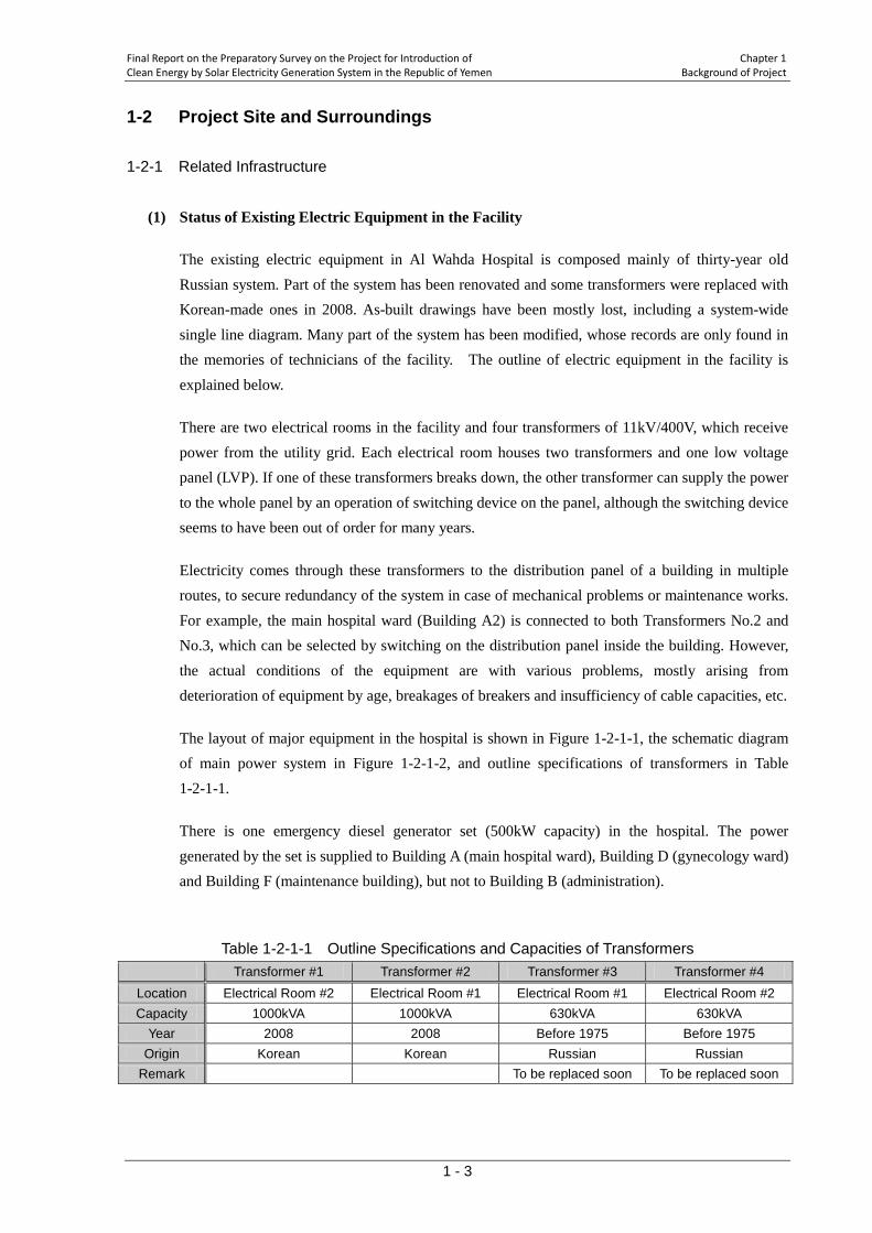
The existing electric equipment in Al Wahda Hospital is composed mainly of thirty-year old Russian system. Part of the system has been renovated and some transformers were replaced with Korean-made ones in 2008. As-built drawings have been mostly lost, including a system-wide single line diagram. Many part of the system has been modified, whose records are only found in the memories of technicians of the facility. The outline of electric equipment in the facility is explained below.
There are two electrical rooms in the facility and four transformers of 11kV/400V, which receive power from the utility grid. Each electrical room houses two transformers and one low voltage panel (LVP). If one of these transformers breaks down, the other transformer can supply the power to the whole panel by an operation of switching device on the panel, although the switching device seems to have been out of order for many years.
Electricity comes through these transformers to the distribution panel of a building in multiple routes, to secure redundancy of the system in case of mechanical problems or maintenance works. For example, the main hospital ward (Building A2) is connected to both Transformers No.2 and No.3, which can be selected by switching on the distribution panel inside the building. However, the actual conditions of the equipment are with various problems, mostly arising from deterioration of equipment by age, breakages of breakers and insufficiency of cable capacities, etc.
The layout of major equipment in the hospital is shown in Figure 1-2-1-1, the schematic diagram of main power system in Figure 1-2-1-2, and outline specifications of transformers in Table 1-2-1-1.
There is one emergency diesel generator set (500kW capacity) in the hospital. The power generated by the set is supplied to Building A (main hospital ward), Building D (gynecology ward) and Building F (maintenance building), but not to Building B (administration).
Table 1-2-1-1 Outline Specifications and Capacities of Transformers
Transformer #1 Transformer #2 Transformer #3 Transformer #4 Location Electrical Room #2 Electrical Room #1 Electrical Room #1 Electrical Room #2 Capacity 1000kVA 1000kVA 630kVA 630kVA
Year 2008 2008 Before 1975 Before 1975 Origin Korean Korean Russian Russian
Remark To be replaced soon To be replaced soon

Chapter 1 Final Report on the Preparatory Survey on the Project for Introduction of Background of Project Clean Energy by Solar Electricity Generation System in the Republic of Yemen
1 - 4
There is a power meter fixed at each of these transformers. In 2008, the total of reads of these meters, that is the annual energy consumption of the hospital, was 2,063,949kWh.
North
Figure 1-2-1-1 Layout of Major Equipment (existing)
Figure 1-2-1-2 Schematic Diagram of Main Power System
TR 3
TR 2
TR 1
TR 4
High Voltage
BLDG-A1
Electric Room #1 Electric Room #2
BLDG-A2
BLDG-B
Other BLDGs
Low Voltage Panel #1
Low Voltage
Other BLDGs
Other BLDGs
DG
500kW Low Voltage Panel #2
A1: MAIN HOSPITAL WARD, 7F (PEDIATRIC) BUILDING NAME LIST
A2: MAIN HOSPITAL WARD, 7F (PEDIATRIC, UNDER RENOVATION) B: ADMINISTRATION C: PHARMACY, LABORATORY, GENERAL SERVICE D: GYNECOLOGY, 5F E: KIDNEY DIALYTIC, 2F F: MAINTENANCE ROOM,1F G: STOREHOUSE H: WATER TANK (UNDERGROUND) I: WATER TANK (H=5000MM) J: NO.2 ELECTRIC ROOM (500KW DG) K: NO.3 ELECTRIC ROOM (NOT USE) L: NO.1 ELECTRIC ROOM M: COFFEE SHOP N: ELECTRICAL ROOM FOR BUILDING B
Final Report on the Preparatory Survey on the Project for Introduction of Chapter 1 Clean Energy by Solar Electricity Generation System in the Republic of Yemen Background of Project
1 - 5
(2) Status of Electricity Supply in the Region
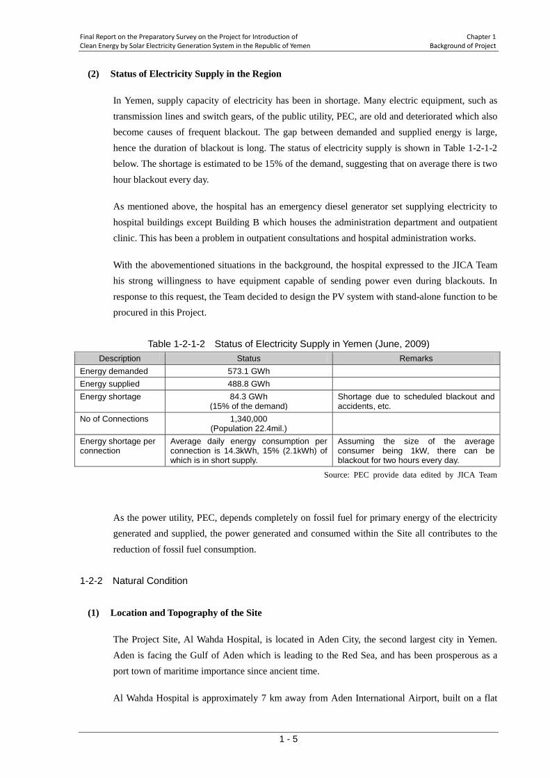
In Yemen, supply capacity of electricity has been in shortage. Many electric equipment, such as transmission lines and switch gears, of the public utility, PEC, are old and deteriorated which also become causes of frequent blackout. The gap between demanded and supplied energy is large, hence the duration of blackout is long. The status of electricity supply is shown in Table 1-2-1-2 below. The shortage is estimated to be 15% of the demand, suggesting that on average there is two hour blackout every day.
As mentioned above, the hospital has an emergency diesel generator set supplying electricity to hospital buildings except Building B which houses the administration department and outpatient clinic. This has been a problem in outpatient consultations and hospital administration works.
With the abovementioned situations in the background, the hospital expressed to the JICA Team his strong willingness to have equipment capable of sending power even during blackouts. In response to this request, the Team decided to design the PV system with stand-alone function to be procured in this Project.
Table 1-2-1-2 Status of Electricity Supply in Yemen (June, 2009)
Description Status Remarks Energy demanded 573.1 GWh Energy supplied 488.8 GWh Energy shortage 84.3 GWh
(15% of the demand) Shortage due to scheduled blackout and accidents, etc.
No of Connections 1,340,000 (Population 22.4mil.)
Energy shortage per connection
Average daily energy consumption per connection is 14.3kWh, 15% (2.1kWh) of which is in short supply.
Assuming the size of the average consumer being 1kW, there can be blackout for two hours every day.
Source: PEC provide data edited by JICA Team
As the power utility, PEC, depends completely on fossil fuel for primary energy of the electricity generated and supplied, the power generated and consumed within the Site all contributes to the reduction of fossil fuel consumption.
1-2-2 Natural Condition
(1) Location and Topography of the Site
The Project Site, Al Wahda Hospital, is located in Aden City, the second largest city in Yemen. Aden is facing the Gulf of Aden which is leading to the Red Sea, and has been prosperous as a port town of maritime importance since ancient time.
Al Wahda Hospital is approximately 7 km away from Aden International Airport, built on a flat
Chapter 1 Final Report on the Preparatory Survey on the Project for Introduction of Background of Project Clean Energy by Solar Electricity Generation System in the Republic of Yemen
1 - 6
land of approximately 300m by 300m rectangle. The perimeter of the premise is lined with fence made of concrete blocks. The PV system procured by the Project will be installed in the open, flat area in the southern part of the premise.
(2) Meteorological Conditions
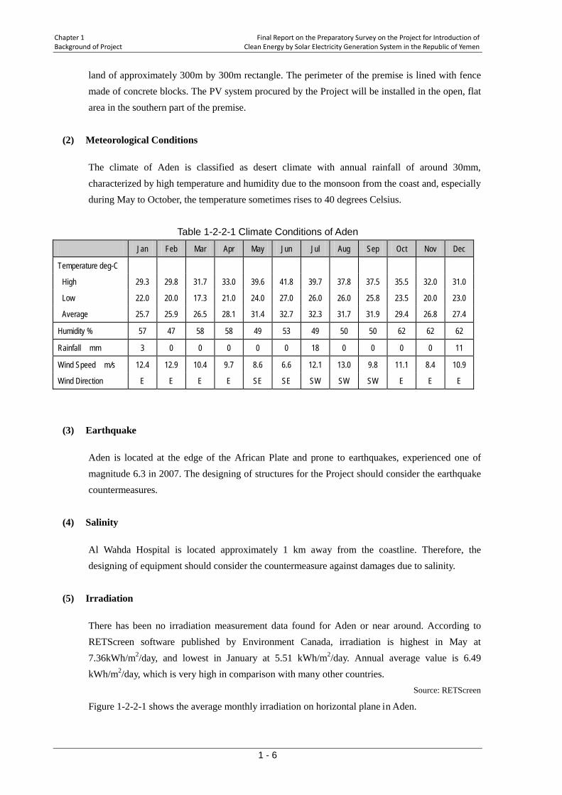
The climate of Aden is classified as desert climate with annual rainfall of around 30mm, characterized by high temperature and humidity due to the monsoon from the coast and, especially during May to October, the temperature sometimes rises to 40 degrees Celsius.
Table 1-2-2-1 Climate Conditions of Aden
Jan Feb Mar Apr May Jun Jul Aug Sep Oct Nov Dec
Temperature deg-C
High 29.3 29.8 31.7 33.0 39.6 41.8 39.7 37.8 37.5 35.5 32.0 31.0
Low 22.0 20.0 17.3 21.0 24.0 27.0 26.0 26.0 25.8 23.5 20.0 23.0
Average 25.7 25.9 26.5 28.1 31.4 32.7 32.3 31.7 31.9 29.4 26.8 27.4
Humidity % 57 47 58 58 49 53 49 50 50 62 62 62
Rainfall mm 3 0 0 0 0 0 18 0 0 0 0 11
Wind Speed m/s 12.4 12.9 10.4 9.7 8.6 6.6 12.1 13.0 9.8 11.1 8.4 10.9
Wind Direction E E E E SE SE SW SW SW E E E
(3) Earthquake
Aden is located at the edge of the African Plate and prone to earthquakes, experienced one of magnitude 6.3 in 2007. The designing of structures for the Project should consider the earthquake countermeasures.
(4) Salinity
Al Wahda Hospital is located approximately 1 km away from the coastline. Therefore, the designing of equipment should consider the countermeasure against damages due to salinity.
(5) Irradiation
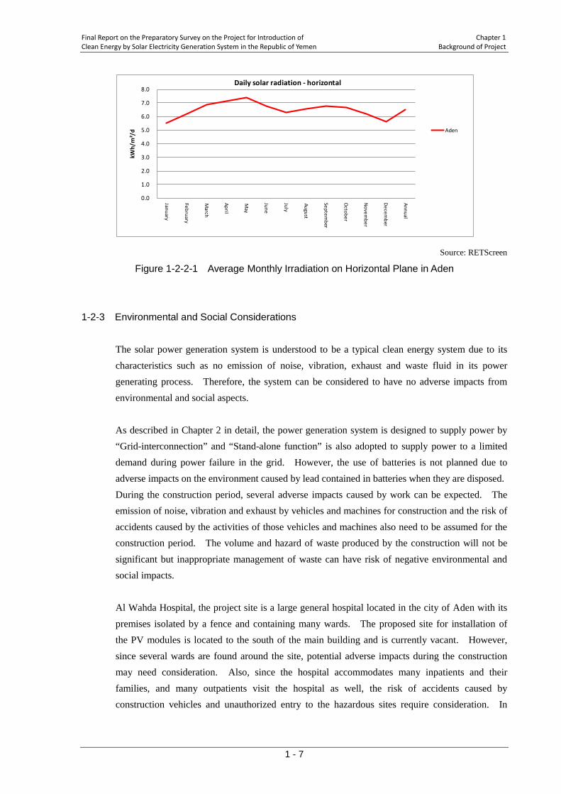
There has been no irradiation measurement data found for Aden or near around. According to RETScreen software published by Environment Canada, irradiation is highest in May at 7.36kWh/m2/day, and lowest in January at 5.51 kWh/m2/day. Annual average value is 6.49 kWh/m2/day, which is very high in comparison with many other countries.
Source: RETScreen
Figure 1-2-2-1 shows the average monthly irradiation on horizontal plane in Aden.
Final Report on the Preparatory Survey on the Project for Introduction of Chapter 1 Clean Energy by Solar Electricity Generation System in the Republic of Yemen Background of Project
1 - 7
Source: RETScreen
Figure 1-2-2-1 Average Monthly Irradiation on Horizontal Plane in Aden 1-2-3 Environmental and Social Considerations
The solar power generation system is understood to be a typical clean energy system due to its characteristics such as no emission of noise, vibration, exhaust and waste fluid in its power generating process. Therefore, the system can be considered to have no adverse impacts from environmental and social aspects. As described in Chapter 2 in detail, the power generation system is designed to supply power by “Grid-interconnection” and “Stand-alone function” is also adopted to supply power to a limited demand during power failure in the grid. However, the use of batteries is not planned due to adverse impacts on the environment caused by lead contained in batteries when they are disposed. During the construction period, several adverse impacts caused by work can be expected. The emission of noise, vibration and exhaust by vehicles and machines for construction and the risk of accidents caused by the activities of those vehicles and machines also need to be assumed for the construction period. The volume and hazard of waste produced by the construction will not be significant but inappropriate management of waste can have risk of negative environmental and social impacts. Al Wahda Hospital, the project site is a large general hospital located in the city of Aden with its premises isolated by a fence and containing many wards. The proposed site for installation of the PV modules is located to the south of the main building and is currently vacant. However, since several wards are found around the site, potential adverse impacts during the construction may need consideration. Also, since the hospital accommodates many inpatients and their families, and many outpatients visit the hospital as well, the risk of accidents caused by construction vehicles and unauthorized entry to the hazardous sites require consideration. In
0.0
1.0
2.0
3.0
4.0
5.0
6.0
7.0
8.0
January
February
March
April
May
June
July
August
September
October
Novem
ber
Decem
ber
Annual
kWh/
m²/
d
Daily solar radiation - horizontal
Aden
Chapter 1 Final Report on the Preparatory Survey on the Project for Introduction of Background of Project Clean Energy by Solar Electricity Generation System in the Republic of Yemen
1 - 8
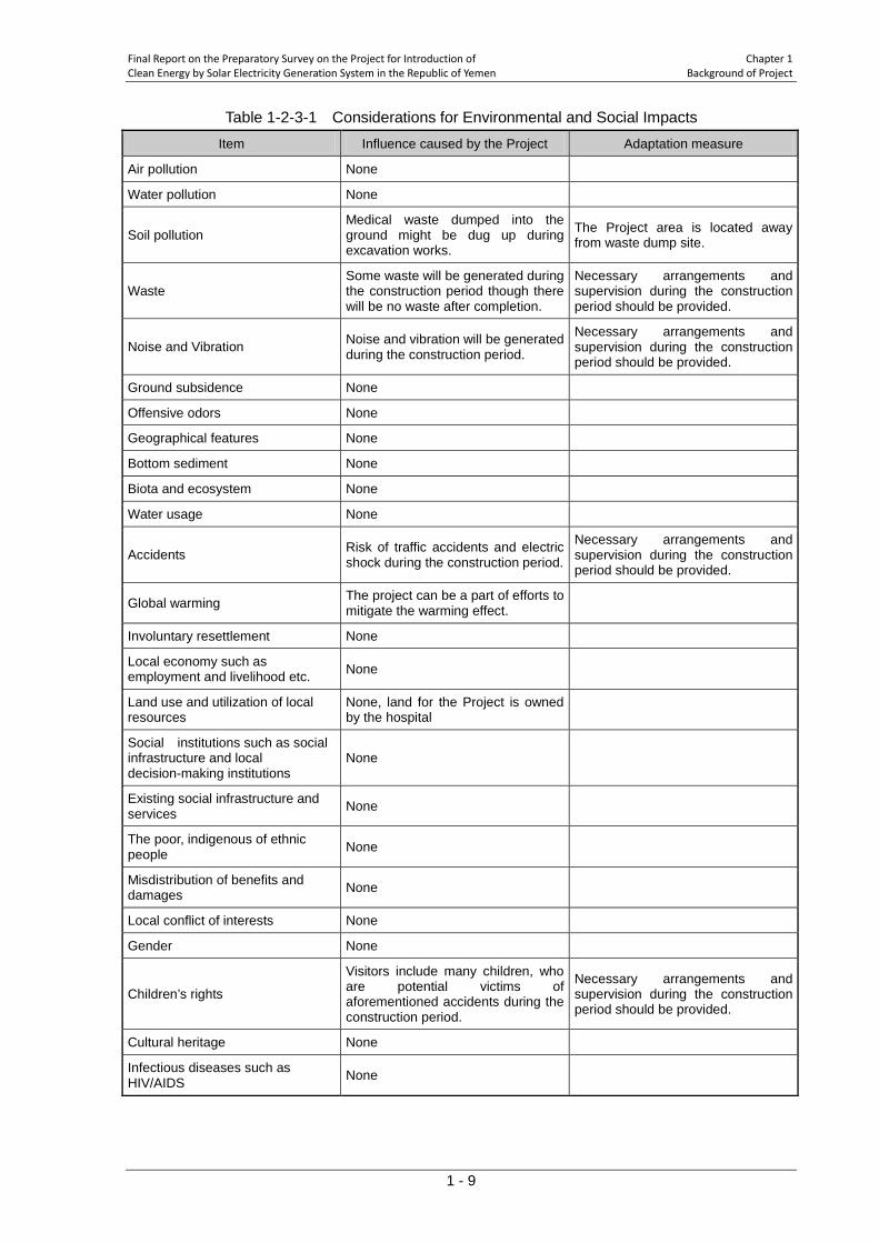
addition, hindrance to surrounding traffic during the peak period for delivery of equipment, material and machinery can be assumed. In order to mitigate the above mentioned adverse impacts during the construction period, appropriate mitigation measures which needs to be planned and implemented by the Contractor is required. Informing the work schedule and time table to the hospital staff, patients and neighbors in order for them to understand clearly the work procedures is also important to avoid the adverse impacts. As more concrete measures for security, the installation of temporary fencing to guard the site and arrangements for security guards will be required by the Contractor. Fencing around the system is planned to prevent electrical shock due to entry of unauthorized persons even after completion of the work. The screening was carried out during the field survey to confirm the categorization of the project which was set as “C” according to JICA’s guidelines for environmental and social considerations (2004) at the beginning of the study. The following table shows the results of the screening. The items are listed in accordance with the scope of objects in JICA’s guidelines.
Final Report on the Preparatory Survey on the Project for Introduction of Chapter 1 Clean Energy by Solar Electricity Generation System in the Republic of Yemen Background of Project
1 - 9
Table 1-2-3-1 Considerations for Environmental and Social Impacts Item Influence caused by the Project Adaptation measure
Air pollution None
Water pollution None
Soil pollution Medical waste dumped into the ground might be dug up during excavation works.
The Project area is located away from waste dump site.
Waste Some waste will be generated during the construction period though there will be no waste after completion.
Necessary arrangements and supervision during the construction period should be provided.
Noise and Vibration Noise and vibration will be generated during the construction period.
Necessary arrangements and supervision during the construction period should be provided.
Ground subsidence None
Offensive odors None
Geographical features None
Bottom sediment None
Biota and ecosystem None
Water usage None
Accidents Risk of traffic accidents and electric shock during the construction period.
Necessary arrangements and supervision during the construction period should be provided.
Global warming The project can be a part of efforts to mitigate the warming effect.
Involuntary resettlement None
Local economy such as employment and livelihood etc. None
Land use and utilization of local resources
None, land for the Project is owned by the hospital
Social institutions such as social infrastructure and local decision-making institutions
None
Existing social infrastructure and services None
The poor, indigenous of ethnic people None
Misdistribution of benefits and damages None
Local conflict of interests None
Gender None
Children’s rights
Visitors include many children, who are potential victims of aforementioned accidents during the construction period.
Necessary arrangements and supervision during the construction period should be provided.
Cultural heritage None
Infectious diseases such as HIV/AIDS None
Chapter 1 Final Report on the Preparatory Survey on the Project for Introduction of Background of Project Clean Energy by Solar Electricity Generation System in the Republic of Yemen
1 - 10
As shown in the table, the impacts from the project will occur mostly during the construction period. Therefore, it is considered that long-term serious impacts, if any, can be avoided or mitigated through the execution of appropriate measures at the beginning stage of the project implementation. Based on the above procedure, the project was confirmed to be categorized as “C” again at the stage of site survey. The Environment Protection Authority (EPA) is in charge of supervision of the environmental Impact Assessment (EIA) in Yemen, complying with the relevant provisions of the Environment Protection Law (1995). In accordance with the law, any project which might have adverse impact on the environment must be assessed by the EIA procedure. During the meeting with EPA, the Team explained about the outline of the Project and EPA suggested to the Team that negative impacts likely to be caused by the project would be quite limited due to the following reasons: - Photovoltaic solar power planned for the project is regarded as clean energy. - Size of the project can be considered as small scale. - Site of the project is to be located on the land owned by the beneficiary. The Team then resumed the consultation with EPA by explaining the results of the screening which indicated that the project would not be required to undergo the process of EIA in accordance with JICA's guideline for environmental and social considerations. The above was confirmed between EPA and the Team.
1-3 Global Issues
Global warming caused by greenhouse gas (GHG) emission including carbon dioxide is considered to be the main factor of the climate change, regarded as the global issue today. In particular, since the formation of United Nations Framework Convention on Climate Change, it is unanimously agreed that the reduction of CO2 emission would be unattainable without a contribution from developing countries, as well as developed countries. Solar generation is very effective in the reduction of CO2 emission and the cost of energy production is not affected by fuel. Therefore, solar generation offers additional energy source and the reduction of CO2 emission at a stable cost, and enables developing countries especially to contribute in the global community and to obtain energy for domestic development, at the same time. This Project has been initiated by the participation of Yemen to Cool Earth Partnership. It is expected that the Project contribute to both the development of Yemen and alleviation of climate change as the global issue.

CHAPTER 2 CONTENTS OF THE PROJECT
Final Report on the Preparatory Survey on the Project for Introduction of Chapter 2 Clean Energy by Solar Electricity Generation System in the Republic of Yemen Construction of the Project
2 - 1
Chapter 2 Contents of the Project
2-1 Outline of the Project In the Republic of Yemen, more than half of the electricity comes from steam turbine generators burning fuel oil, and the rest from diesel engine generators. It has been completely dependent on fossil fuel for primary source of electricity. The country has been seeking to diversify into natural gas, and also in rural electrification, clean energy sources including solar power. Renewable Energy Strategy and Action Plan published in June 2008 aims to supply electricity in rural areas with off-grid solar, wind and their diesel-hybrid. In April 2009 the government of Yemen issued a republic law concerning a set up of the public rural electrification authority to plan and select appropriate low-cost energy supply schemes including those using new and renewable energy which best meet the energy needs in rural areas. The country decided to join "Cool Earth Partnership" and takes up as its policy priority a reduction of GHGs emission and promotioin of economic development, by the approach of adaptation and mitigation to climate change. This Project is to provide Al Wahda Hospital in Aden, Yemen with a photovoltaic system (PV system) of 300kW peak power and to supply electric power to the facility. The Project will contribute to the Yemeni policy of reduction of GHGs emission and the promotion of economic development, by supplying renewable energy to replace electricity generated by the conventional methods, and reducing the country's dependence on fossil fuel and relieving the burden of energy cost of the facility. The PV system works with the power from the utility grid (grid interconnection), but does not send its surplus power, if any, back to the grid. In the case of blackout of grid power the system can be re-started in “stand alone mode” by manual operation to send power to limited part of the facility. This Project is conducted under the scheme the Programme Grant Aid for Environment and Climate Change and the tendering for the contract for the procurement of equipments and construction shall be held for Japanese companies. Among the various products to be procured for the Project, PV modules and power conditioners shall be limited to Japanese products. Site works including civil engineering works for foundations, installation of PV modules and electric works, is assumed to be undertaken and managed by the Japanese contractor employing private companies in the recipient country.
Chapter 2 Final Report on the Preparatory Survey on the Project for Introduction of Construction of the Project Clean Energy by Solar Electricity Generation System in the Republic of Yemen
2 - 2
2-2 Basic Design of the Project 2-2-1 Design Policy 2-2-1-1 Design of the System
This Project is to procure and install a PV system (300kW) with grid interconnection to Al Wahda Hospital in Aden City. Al Wahda Hospital is, being a referral hospital, one of the most important medical facilities in the southern region of the county, with its large scale, collecting users/patients from surrounding Governorates. As it is located in Aden City which is famous for its high temperature, the Hospital demands large amount of electricity during daytime for its inevitable air conditioning, which is suitable characteristics for photovoltaic power. Therefore, the Project will prove to be very effective and valuable, as a mitigation measure of climate change, to furnish the Hospital with a photovoltaic generation system. The capacity of the PV system shall be determined taking into account the current electric power consumption and the future demand of main hospital wards which are currently under renovation. The provision of the system shall be confirmed to be free from any interference with other aid agency’s activities and the installation area selected properly in view of the future land use of, and with approval from, the Hospital. The PV system procured in the Project will be interconnected, as a prerequisite, to the power grid of Public Electricity Corporation of Yemen (PEC). It will be the first-ever experience for PEC to have a grid-interconnected renewable resource power generation, and there is no institutional/regulatory provisions in the country so far. PEC had understood the technical explanations provided by JICA Team and gave his judgment that he accepts the grid-interconnection of the PV system but not the reverse power flow1
of the PV system, as there are no regulations concerning the matter. Therefore, the system is designed to produce power to be supplied to and consumed within the facility, and to suppress power production when it exceeds the consumption in the facility so that there will not be surplus power to be sent upstream to the grid.
The PV system shall be designed to shut down automatically when there is blackout of utility grid power. After having confirmed some predetermined conditions being met, the System shall be able to be restarted, disconnected from the utility grid, by manual operation to supply power to limited part of the facility. This function, called "stand-alone mode" is adopted in the design responding to the strong demand expressed by the Hospital. The Hospital is equipped with emergency diesel
1 Reverse flow is the flow of power generated by PV system upstream to the utility grid.
Final Report on the Preparatory Survey on the Project for Introduction of Chapter 2 Clean Energy by Solar Electricity Generation System in the Republic of Yemen Construction of the Project
2 - 3
generators for blackout situations. They supply power to parts of the Hospital but not to the administration and outpatient building due to the shortage of supply capacity, which led to the need for the power supply to the said building during the blackout. The part of the facility to be supplied with power under stand-alone mode must be strictly without important loads2
that require stable power supply, in particular those electric equipment that affect human lives, as power production of PV system alone is inherently unstable due to weather conditions and may stop anytime. The loads to be supplied with power under stand-alone mode should be limited to those dispensable, such as air conditioning and lighting, etc.
2-2-1-2 Natural Condition
(1) Air Temperature and Humidity
As mentioned in sub-section 1-2-2, the climate of Aden has high temperature and humidity throughout the year. Al-Wahda hospital is located relatively near the sea so that the equipments should be salinity resistant.
Power conditioners for the PV system procured in this Project shall be designed to be set in a container cubicle with air conditioning, which relieves the power conditioners of high air temperature outside.
Maximum temperature inside the cubicle shall be set at 27.5 degrees Celsius to protect semiconductors used in power conditioners from the heat. A space heater shall be furnished to the cubicle to prevent the dew condensation due to lowered temperature and high humidity inside the cubicle. Equipment to be installed outside the cubicle shall be designed to work in air temperature as high as 41.8 degrees Celsius. Also, a cubicle containing electric facilities of the system shall be designed with protection level IP 54.
Supporting structures for PV modules and junction boxes shall be designed to be salinity resistant as the site is located near the sea (main members of supporting structure shall comply with HDZ 55, of JIS H 8641 or equivalent, and junction boxes made of stainless steel).
(2) Lightning Strike
According to the interview to related parties of the Site, the Site is not considered prone to lightning strikes.
The countermeasures shall be that against inductive lightning, as the PV arrays are to be lying around two meter high at most, lower than surrounding buildings, and the Site is located within the development of the city, which implies low possibility of .direct lightning strikes. Specifically,
2 Electric equipment that supports human lives, such as respirators.
Chapter 2 Final Report on the Preparatory Survey on the Project for Introduction of Construction of the Project Clean Energy by Solar Electricity Generation System in the Republic of Yemen
2 - 4
junction boxes and power conditioners shall be fitted with arrestors.
(2) Rainfall and Wind
No special consideration is needed for rainfall and wind in the design of the system.
(3) Earthquakes
Aden is located at the edge of the African Plate, and has recently experienced the earthquake of Magnitude 6.3 scale. In the design of this Project, horizontal acceleration of 0.25G level shall be considered.
2-2-1-3 Local Conditions affecting the Works
In Yemen, all the local contractors are eligible to engage in the government's public works projects. However, there are no local contractors that have experiences in a similar project to this Project as this Project is the first-ever large-scale solar project in the country. For construction equipment, local contractors hire equipment from local rental companies as needed. There are many rental equipment companies in Sana’a and the machines are in good condition. As for the experiences in solar system installation, there are some companies that have undertaken installation of electrical equipment for such facilities as antennas for mobile phone, pumping stations, schools and hospitals. These companies employ permanent engineers and technicians. Although they have sufficient capacity to carry out civil works, steel works and plant works in small scale, their ability to handle large scale works like this Project is still unseen. Yemen is a Muslim country, and it is important to appreciate Muslim customs such as Ramadan in planning implementation schedules. The Site is on the property of the hospital, easily accessible by general public including inhabitants of the area. Therefore, it is necessary to report to and discuss the contents and the schedule of the Works with people in charge at the hospital.
2-2-1-4 Application of Local Resource
(1) Utilization of Local Companies
It is assumed the Works at the Site will be managed by a Japanese company as a prime contractor who supervises the individual works sub-contracted and carried out by local companies. Local companies also are assumed to carry out, providing equipment and manpower, the installation works of electric equipment. The Works at the Site include; civil works (earth works, concrete
Final Report on the Preparatory Survey on the Project for Introduction of Chapter 2 Clean Energy by Solar Electricity Generation System in the Republic of Yemen Construction of the Project
2 - 5
foundation works), steel works (fabrication of support structures for PV modules), equipment installation works (PV modules, electric boards and container cubicle), and electric works (laying cables). As the local companies do not have sufficient experiences in the similar projects, experienced engineer(s) will have to be sent from Japan or other countries to the Site for quality control, schedule control, safety control, assembling Supervision, testing and adjustment of equipment.
Rental large crane is available in the country and will be used to install the power conditioner cubicle transported from Japan. Local transporter’s vehicle can carry 40 foot container by inland transportation.
(2) Utilization of Local Materials and Equipments
Most of construction materials such as aggregates, cement and reinforcement bars are available in the country. However, electric equipments and materials including PV modules, power conditioners, and cables are not available in the local markets.
2-2-1-5 Capability of Operation and Maintenance
Operation and routine maintenances of the PV system after the commissioning will be done by Al Wahda Hospital under the supervision of MPHP. As the facility owns and has been maintaining power receiving and distributing equipments over a long time to use, the facility is deemed to have reasonable capacity to maintain electric equipment in general. However, the status of existing equipment in the facility indicates inadequate practice and lack of knowledge about maintenances with preventive measures including routine inspections. Therefore, this Project should provide training program on O&M including important daily and periodic inspections, taught by Japanese specialist in two separate periods; one during the commissioning of the PV system, and the other a few months after the commissioning. Spare parts, tool kits, and Operation and Maintenance Manuals for maintaining the PV system should be supplied by the Project as well. In addition, to realize effective and efficient operation and maintenance, a suitable management organization for operations and maintenance should be proposed in the Project. Some parts in the PV system need replacement in the long term and this may cost a significant amount. Such expenses may not be possible for the Facility (Al Wahda Hospital) to bear alone within one-fiscal year budget. It is important that the executing agency (MPHP) is aware of this and is prepared to make financial arrangement with the Facility. As the financial benefit of reduction of power purchase due to power generation is expected to be larger than the above cost, it is also possible to raise a fund from part of such benefit for future maintenance expenses.
Chapter 2 Final Report on the Preparatory Survey on the Project for Introduction of Construction of the Project Clean Energy by Solar Electricity Generation System in the Republic of Yemen
2 - 6
2-2-1-6 Schedule of Procurement and Installation As this Project is conducted in the scheme of the Programme Grant Aid for Environment and Climate Change, it must be conducted in as efficient manner as possible. To complete the Works and produce expected results by the specified time, the Works should be scheduled considering the sequence of inputs from both Japan and the recipient sides, and also, route, method of transportation, time for various official procedures necessary.
2-2-2 Basic Plan (Construction Plan/Equipment Plan) 2-2-2-1 Design Condition
To design the capacity and specification of the PV system, various conditions described above are considered and consequently, the design conditions shall be set as shown below.
(1) Natural and Local Conditions
1. Outdoor air temperature 41.8 degrees Celsius (Maximum) 2. Electric room’s temperature 27.5 degrees Celsius 3. Design relative humidity Maximum 95% 4. Design wind velocity 40.0 m/s 5. Mean annual rainfall 50mm 6. Seismic force to be considered (0.25G horizontal) 7. Elevation of the Site about 2m 8. Load bearing capacity of the ground3
9. Salt damage to be considered 150kN/m2
(2) Applicable Standard 1. Japanese Industrial Standards (JIS) : Industrial products 2. Japanese Electrotechnical Committee (JEC) : Electric products 3. Standards of Japan Electrical Manufacturer's Association (JEM) : Electric products 4. Japanese Electric Wire & Cable Makers’ Association Standard (JCS) : Cables 5. International Electrotechnical Commission (IEC) : Electric products 6. International Organization for Standardization (ISO) : Electric products 7 Technical Standard of Electric Equipment : Electric products
(3) System of Unit
As a general rule, The International System of Units (SI) shall be used
3 As the information was obtained through an interview with local construction company, it should be taken as reference only.

Final Report on the Preparatory Survey on the Project for Introduction of Chapter 2 Clean Energy by Solar Electricity Generation System in the Republic of Yemen Construction of the Project
2 - 7
(4) Electric Mode 1 Nominal voltage (Low voltage) 380V (on-load) 2 Wiring system 3 phases-4 wires (connection point of existing equipments) 3 Frequency 50Hz 4 Earthing method Direct grounding
2-2-2-2 Layout Plan of the PV System
The PV system procured by this Project is constructed on Al Wahda hospital’s premises. Thus, the layout plan of the PV system shall be considered with not only convenience of operations and maintenances but also with following conditions.
- A layout to make the maximum use of solar power in limited space - Efficiency and convenience of construction works - Future land use of the Facility
After the discussion and consultation with the Hospital, it was found that the open area to the south of main building (Building A) is suitable for the installation area of PV modules. The layout of PV modules within the area was studied and the size of the installation was determined as 300kW maximum.
2-2-5-3 Outline of Basic Design
Considering the design policy, basic standard and layout plan described above, the outline of basic design in this Project is as shown Table 2-2-2-1
Table 2-2-2-1 Outline of Basic Design
Category Content
Site and PV Capacity
Al Wahda Hospital: 300kW PV equipment - PV system shall be grid-interconnected - Surplus power shall not be sent back to the utility grid (no reverse current) - In the case of blackout, PV system shall restart in Stand-alone Mode to supply power to part of
the Hospital
Procurement of Generating equipments and Installation Work
300kW PV modules Ancillary equipment and works for PV system
- Junction box - Power conditioner cubicle - Meteorological observation device - Low voltage panel - Branch Switchers for Load (for stand-alone mode) - Materials for wiring and earth - Electrical facility cubicle - Supporting structures for PV modules - Foundation of supporting structures for the PV system and electrical facility cubicle - Fences, gates, and grave surfacing - Cable connection for Electrical facility cubicle/interconnection point/display equipment/
connection to existing loads Spare Parts and Tool Kits
Spare parts and tool kits for maintenances of equipment Manuals for O&M and implementation of O&M Guidance
Chapter 2 Final Report on the Preparatory Survey on the Project for Introduction of Construction of the Project Clean Energy by Solar Electricity Generation System in the Republic of Yemen
2 - 8
2-2-2-4 Outline of Equipment Plan Elements of the PV system which will be installed at Al Wahda hospital are described below. Outline specification of the each equipment is shown in Table 2-2-2-7 and Table 2-2-2-8.
(1) Outline
1) Type of PV System
Type of the PV system is of grid interconnected without storage battery. Storage battery is not included as it would require large replacement cost and the disposition of used batteries may become environmentally hazardous.
2) Operation during the Power Failure
The PV system will be designed to shut down and the interconnection cut off automatically when there is blackout of utility grid power. After having confirmed some predetermined conditions being met, the System will be able to be restarted, disconnected from the utility grid in "stand-alone mode" by manual operation to supply power to limited part of the facility.
Conditions that have to be met to start, and that lead to the shutdown of, the stand-alone operation are as follows.
Necessary conditions: all the following conditions have to be met to start stand-alone mode;
To start up
1. Voltage of the grid has been nil for more than a pre-specified time,
2. Voltage of direct current generated by PV modules is above a pre-specified level, 3. The system control has been given permission to use the stand-alone mode, 4. "start button" has been pushed, or "automatic start" has been selected, 5. Other conditions specified by the manufacturer have been met.
Negative conditions: stand-alone mode does not run when any of the following conditions exist 1. Total load at the destination of stand-alone mode power exceeds the current output of
the PV system, 2. Other conditions specified by the manufacturer exist.
Stand-alone mode is shut down when any of the following conditions exist
Shutdown
1. Voltage of the grid has been back to proper level for more than a pre-specified time,
2. Voltage of direct current generated by PV modules has fallen below a pre-specified level,
3. Operation hours of the day has been over,
Final Report on the Preparatory Survey on the Project for Introduction of Chapter 2 Clean Energy by Solar Electricity Generation System in the Republic of Yemen Construction of the Project
2 - 9
4. "shutdown" button has been pushed at the control panel, 5. Other conditions or orders issued by the system controller (e.g., emergency shutdown).
The system will be designed to start and stop the stand-alone operation either manually or automatically. For some period after the commissioning of the system, it is highly recommended that this be done by manual operation, in order to facilitate the operators' understanding of the operation. Automatic operation should be wanted nevertheless, and can be activated on the condition that the operators and staff of the facility understand the pros and cons of the stand-alone operation. It is because the occurrence of blackout is frequent and unexpected, and manual operation of stand-alone mode can be too troublesome to the operators, which may eventually lead to the situation where the power is not properly supplied to the facility.
The choice of methods of starting/shutting down stand-alone mode does not affect occurrence of malfunctions or lifetime of the PV system. Also, the quality of power of stand-alone operation should not be an issue with respect to the damages to the electric equipment to be supplied thereby, as the protection relays shut down the PV system safely when the quality of power falls below the range of operation,
It should be noted that the PV system cannot be operated in interconnection with the diesel generator (500kW, 400V) existing at the facility during blackout.
Concerning "Stand-Alone" function of the PV system, there are important points that must be understood by the users and related parties of the Recipient side, which are shown below. This was repeatedly explained to the recipient during site surveys and there has been understanding established by the responsible and executing organizations.
A. Instability of PV system under stand-alone mode
The use of the stand-alone function of the PV system must be made with a good understanding that its output is unstable.
Specifically, the output of PV system varies due to irradiation. There is no power production during the night, and in rainy or cloudy weather, the output is lower than in sunny weather. Even on a fine day, the output may suddenly fall when a cloud casts a shadow on PV modules. The instant the output of the PV system falls below the power being demanded, the PV system automatically shuts down.
Although the specific operation of the shutting down depends on the design of the manufacturer, it will be generally as follows.
In stand-alone operation, inverters (power conditioners) run under "constant voltage" control. The power generated by PV modules is dependent on the radiation and may fall below the level demanded by the load. If this happens, inverters cannot maintain the voltage within the allowable range of the constant voltage control due to the lack of power. This drop of voltage triggers shutdown of the system, which is immediately followed by automatic opening of
Chapter 2 Final Report on the Preparatory Survey on the Project for Introduction of Construction of the Project Clean Energy by Solar Electricity Generation System in the Republic of Yemen
2 - 10
conductors, and the system is cut off from the connection.
B. Inappropriate connection of important loads
The destination of power generated by the PV system under the stand-alone mode must not include important loads, such as medical equipment which support human lives (e.g., respirator) and those that affect assets and properties of people or enterprises (e.g., IT equipment of financial institutes) .
Such important loads are usually supported by multiple power sources, not by single source such as grid power only or diesel generator only, even in developed countries where utility grid power is much stable and reliable. Important loads should be furnished with UPS (Uninterruptible Power Supply) and/or other auxiliary power unit.
C. Limitation on the size of electricity consumption of connected equipment
Capacity of PV system under stand-alone mode is quite limited, maximum 20 to 30% of peak capacity. At the destinations of power generated by the PV system under the stand-alone mode, electricity consumption of equipment should be checked to make sure the total of such consumption does not exceed the limit.
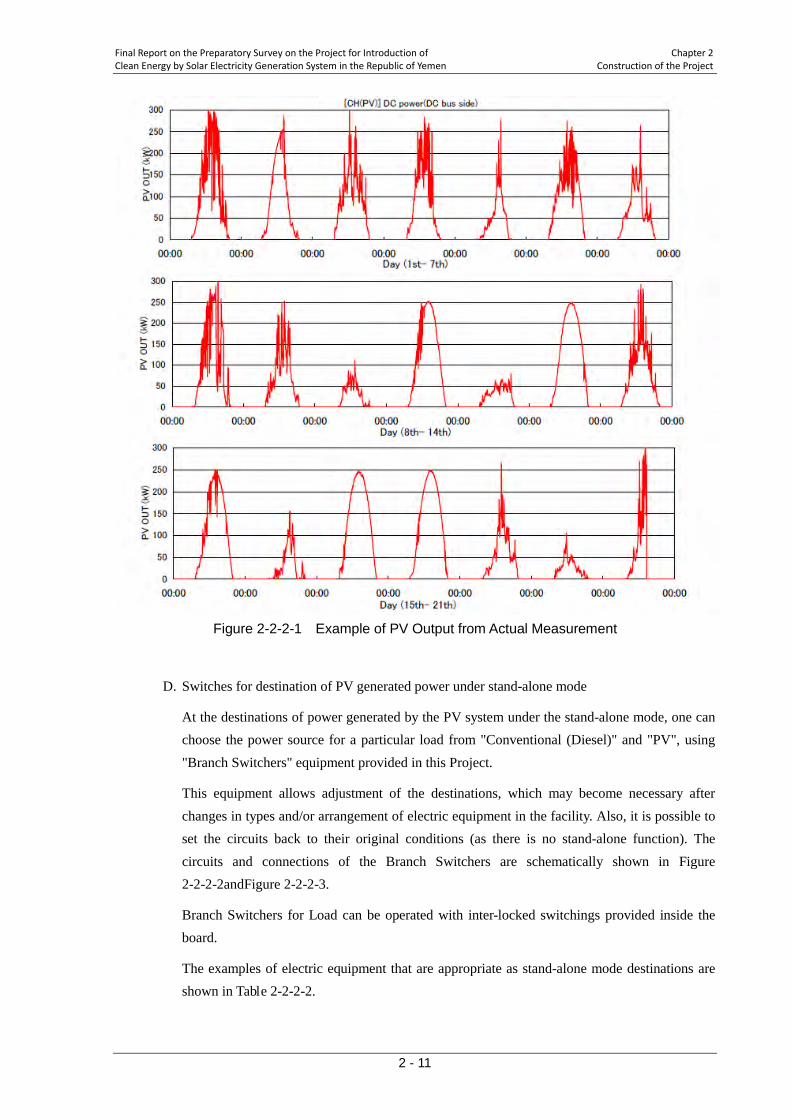
<Case Study>
As an example, the actual recorded output of a 300kW grid-connected PV power plant is shown below. In the figure, vertical axis is for the output of PV system and the horizontal for the time. Output of PV in theory is like a sine curve taken for only positive side, and each peak in the chart corresponds to midday peak.
The output shown in the figure reveals that, in the stand-alone mode where weather-dependent PV is the only source of power, the capacity of the power source significantly fluctuates. Therefore, it becomes much more reliable to use the power for smaller load.
This gives the limitation to the total of the load that is supplied with power under stand-alone mode. The load must be examined and deliberately arranged.
Final Report on the Preparatory Survey on the Project for Introduction of Chapter 2 Clean Energy by Solar Electricity Generation System in the Republic of Yemen Construction of the Project
2 - 11
Figure 2-2-2-1 Example of PV Output from Actual Measurement
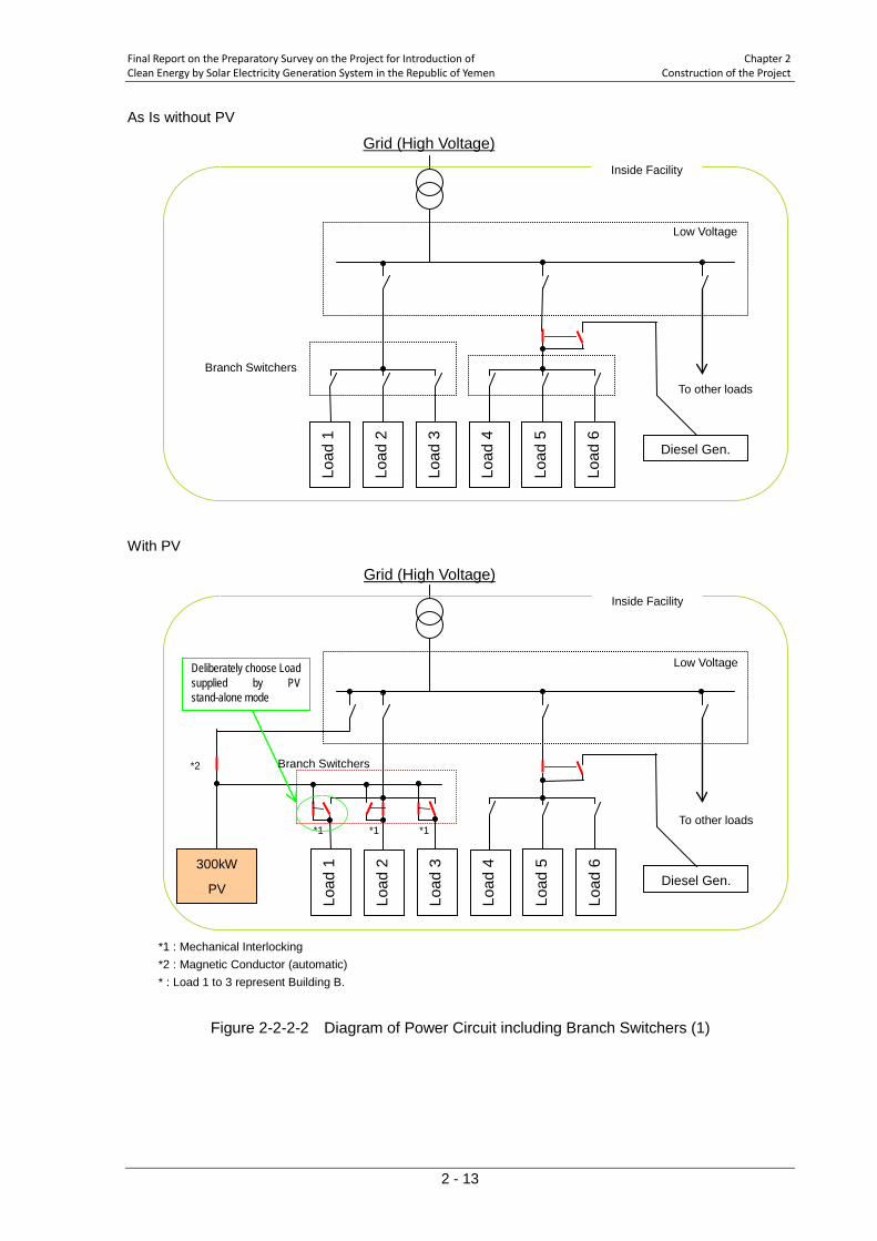
D. Switches for destination of PV generated power under stand-alone mode
At the destinations of power generated by the PV system under the stand-alone mode, one can choose the power source for a particular load from "Conventional (Diesel)" and "PV", using "Branch Switchers" equipment provided in this Project.
This equipment allows adjustment of the destinations, which may become necessary after changes in types and/or arrangement of electric equipment in the facility. Also, it is possible to set the circuits back to their original conditions (as there is no stand-alone function). The circuits and connections of the Branch Switchers are schematically shown in Figure 2-2-2-2andFigure 2-2-2-3.
Branch Switchers for Load can be operated with inter-locked switchings provided inside the board.
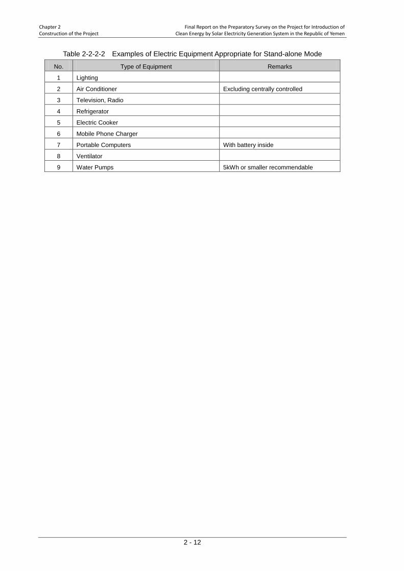
The examples of electric equipment that are appropriate as stand-alone mode destinations are shown in Table 2-2-2-2.
Chapter 2 Final Report on the Preparatory Survey on the Project for Introduction of Construction of the Project Clean Energy by Solar Electricity Generation System in the Republic of Yemen
2 - 12
Table 2-2-2-2 Examples of Electric Equipment Appropriate for Stand-alone Mode
No. Type of Equipment Remarks
1 Lighting
2 Air Conditioner Excluding centrally controlled
3 Television, Radio
4 Refrigerator
5 Electric Cooker
6 Mobile Phone Charger
7 Portable Computers With battery inside
8 Ventilator
9 Water Pumps 5kWh or smaller recommendable
Final Report on the Preparatory Survey on the Project for Introduction of Chapter 2 Clean Energy by Solar Electricity Generation System in the Republic of Yemen Construction of the Project
2 - 13
As Is without PV
With PV
*1 : Mechanical Interlocking *2 : Magnetic Conductor (automatic) * : Load 1 to 3 represent Building B.
Figure 2-2-2-2 Diagram of Power Circuit including Branch Switchers (1)
300kW
PV
*1
*1
*1
*2
Deliberately choose Load supplied by PV stand-alone mode
To other loads
Grid (High Voltage)
Low Voltage
Branch Switchers
Inside Facility
Diesel Gen.
Load
1
Load
2
Load
3
Load
4
Load
5
Load
6
Load
1
Load
2
Load
3
Load
4
Load
5
Load
6
Grid (High Voltage)
To other loads
Low Voltage
Branch Switchers
Inside Facility
Diesel Gen.
Chapter 2 Final Report on the Preparatory Survey on the Project for Introduction of Construction of the Project Clean Energy by Solar Electricity Generation System in the Republic of Yemen
2 - 14
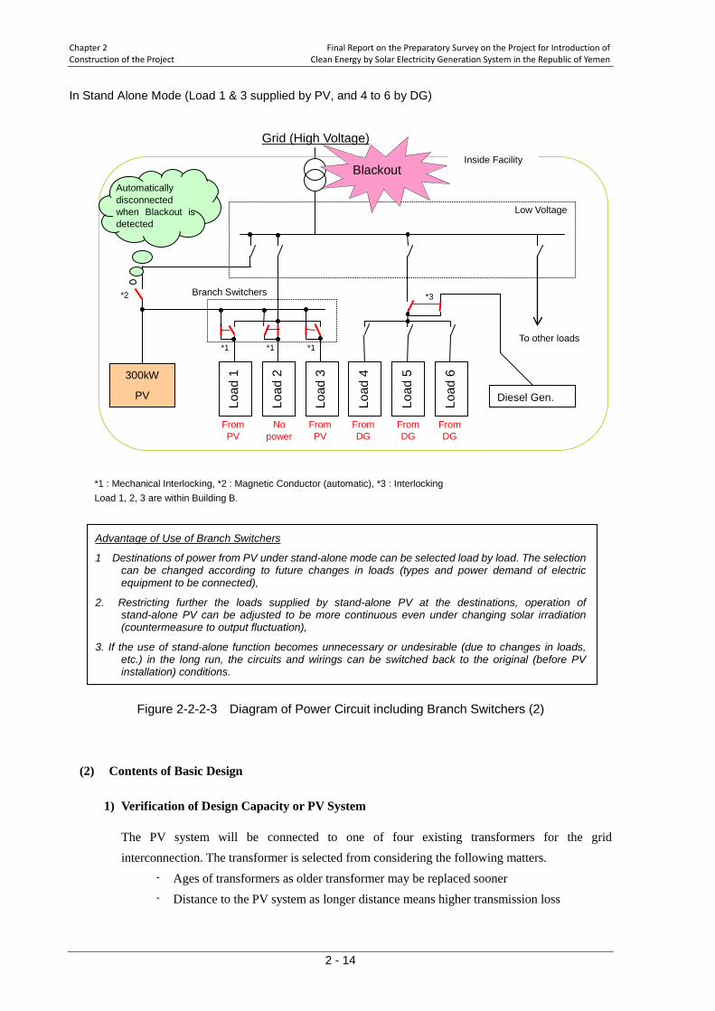
In Stand Alone Mode (Load 1 & 3 supplied by PV, and 4 to 6 by DG)
*1 : Mechanical Interlocking, *2 : Magnetic Conductor (automatic), *3 : Interlocking Load 1, 2, 3 are within Building B.
1 Destinations of power from PV under stand-alone mode can be selected load by load. The selection can be changed according to future changes in loads (types and power demand of electric equipment to be connected),
Advantage of Use of Branch Switchers
2. Restricting further the loads supplied by stand-alone PV at the destinations, operation of stand-alone PV can be adjusted to be more continuous even under changing solar irradiation (countermeasure to output fluctuation),
3. If the use of stand-alone function becomes unnecessary or undesirable (due to changes in loads, etc.) in the long run, the circuits and wirings can be switched back to the original (before PV installation) conditions.
Figure 2-2-2-3 Diagram of Power Circuit including Branch Switchers (2)
(2) Contents of Basic Design
1) Verification of Design Capacity or PV System
The PV system will be connected to one of four existing transformers for the grid interconnection. The transformer is selected from considering the following matters.
- Ages of transformers as older transformer may be replaced sooner - Distance to the PV system as longer distance means higher transmission loss
300kW
PV
*1
*1
*1
*2
From PV
No power
From PV
Blackout Automatically disconnected when Blackout is detected
From DG
From DG
From DG
Diesel Gen.
*3
To other loads
Grid (High Voltage)
Low Voltage
Branch Switchers
Inside Facility
Load
1
Load
2
Load
3
Load
4
Load
5
Load
6

Final Report on the Preparatory Survey on the Project for Introduction of Chapter 2 Clean Energy by Solar Electricity Generation System in the Republic of Yemen Construction of the Project
2 - 15
- Balance between the load connected to the transformer and the peaking capacity of the PV system, as the surplus power is not allowed to be sent to the utility grid.
Transformer No.2 meets most the conditions above and should be selected as the interconnection point.
Next, capacity of the PV system is considered. The main loads of Transformer No. 2 are as shown below.
- Building A (Main hospital ward; 7 storeys) - Building B (Administration, out-patient clinic, X-ray; 2 storeys) - Building F (Maintenance and operation section; one storey) - Own load of the electrical room
The actual electric power consumption measured of the Transformer No.2 was about 222kW at maximum. But, the loads connected to Transformer No. 2 are expected to increase in the future by the following factors.
♦ Completion of renovation of Building A Western half portion of Building A is currently under renovation. This renovation will be finished around 2011 and the loads are expected to increase for about 4000 sq meters of
floor area (13.6 m × 61.0 m × 5 storeys). Expected types of loads are electric lights and some equipment with large electric consumption, such as air conditioners. If an air conditioner is installed at every room, the increase of loads will be about 180kW (25 rooms
× 5 floors × 1.5kW per air conditioner). Another X-ray scanner made in Japan has been installed in Building A after the site study. Power consumption of this additional scanner is about 100kVA.
♦ Replacement of wiring and the low voltage panel at Building B There are two lines of wiring to Building B; from Transformer No. 2 and Transformer No. 3. Power sent from these transformers to Building B is both about 100kW. These loads are limited due to the shortages of capacities of cables and of capacities of breakers the low voltage panel in Building B. For example, two X-rays equipped in Building B are not able to work at the same moment because of these limitations. Therefore, the renewal of some equipment derived from this Project will increase the load of Building B.
The loads of Building B are listed in Table 2-2-2-3. Present capacity of installation in Building B in total is about 370kW. Al Wahda Hospital technicians estimate the increase of electric power demand by renewal of equipment about 100kW in the future.

Chapter 2 Final Report on the Preparatory Survey on the Project for Introduction of Construction of the Project Clean Energy by Solar Electricity Generation System in the Republic of Yemen
2 - 16
Table 2-2-2-3 Load List of Building B
Name Light Air conditioner X-ray1 X-ray2 Fans Refrigerator Others Computer
Device of dental clinic
Capacity 80W 10A 100A, 3ph
60A, 3ph 100W 1.5A 6A - -
Number of load(s) 200 57 1 1 70 14 4 10 2
Operating day/hours
8:00- 13:00
8:00- 13:00
24 hour stand-by
24 hour stand-by
8:00- 13:00 24 hour 8:00-
13:00 8:00- 13:00
8:00- 13:00
In summary, electric power consumption of Transformer No. 2 is estimated to increase at maximum to around 600kW; 222kW (present energy consumption), about 280kW (due to renovation of Building A plus new CT scanner), and about 100kW (due to renewal of Building B).
As mentioned before, the installation area gives the upper limit of the installation size. Meanwhile the judgment of no reverse flow demands that the electricity generated should be consumed within the facility as much as possible. Considering these conditions, the capacity of 300kW of the PV system in this Project was found appropriate.
As there was no actual insolation measurement data for the Site available to the Team, the annual energy production was estimated using software called RETScreen, developed and distributed by Natural Resources Canada. The result shows that 500MWh of energy is expected from the system. This energy is approximately 25% of annual power consumption of the Hospital. However, in reality, the energy produced will be smaller than this potential: when the demand is smaller than the production possible the output will be suppressed, and during the blackout of the grid power the system will send power to the limited part of the Hospital under Stand-alone mode. Therefore, the production of 500MWh of energy should be considered theoretical maximum.
The size of the PV equipment of the Project is finally determined, with due consideration of the budgetary size assumed at the earlier stage of the Study and the effective size and shape of installation area for PV modules.
2) Type of PV Module
There are various types of solar cells depending on semiconductors used. Main types of solar cells are silicon and compound. Silicon type has been and is the majority in the market. Silicon type is further classified into crystal and thin film types. Silicon type is made of once melted and molded matrix sliced into thin wafers. Thin film type is made of extremely thin silicon film developed on a sheet of glass by plasma. Although thin film has the advantage of larger production scale, it still has a performance issues to be solved.
With regard to the conversion efficiency, a recent technical report shows that thin film yields higher efficiency measured in annually produced energy, a few percentage points higher, than
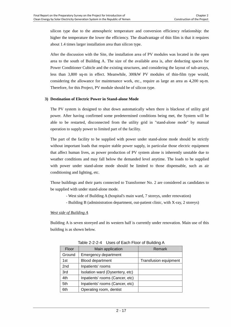
Final Report on the Preparatory Survey on the Project for Introduction of Chapter 2 Clean Energy by Solar Electricity Generation System in the Republic of Yemen Construction of the Project
2 - 17
silicon type due to the atmospheric temperature and conversion efficiency relationship: the higher the temperature the lower the efficiency. The disadvantage of thin film is that it requires about 1.4 times larger installation area than silicon type.
After the discussion with the Site, the installation area of PV modules was located in the open area to the south of Building A. The size of the available area is, after deducting spaces for Power Conditioner Cubicle and the existing structures, and considering the layout of sub-arrays, less than 3,800 sq-m in effect. Meanwhile, 300kW PV modules of thin-film type would, considering the allowance for maintenance work, etc., require as large an area as 4,200 sq-m. Therefore, for this Project, PV module should be of silicon type.
3) Destination of Electric Power in Stand-alone Mode
The PV system is designed to shut down automatically when there is blackout of utility grid power. After having confirmed some predetermined conditions being met, the System will be able to be restarted, disconnected from the utility grid in "stand-alone mode" by manual operation to supply power to limited part of the facility.
The part of the facility to be supplied with power under stand-alone mode should be strictly without important loads that require stable power supply, in particular those electric equipment that affect human lives, as power production of PV system alone is inherently unstable due to weather conditions and may fall below the demanded level anytime. The loads to be supplied with power under stand-alone mode should be limited to those dispensable, such as air conditioning and lighting, etc.
Those buildings and their parts connected to Transformer No. 2 are considered as candidates to be supplied with under stand-alone mode. - West side of Building A (hospital's main ward, 7 storeys, under renovation) - Building B (administration department, out-patient clinic, with X-ray, 2 storeys)
Building A is seven storeyed and its western half is currently under renovation. Main use of this building is as shown below.
West side of Building A
Table 2-2-2-4 Uses of Each Floor of Building A
Floor Main application Remark Ground Emergency department 1st Blood department Transfusion equipment 2nd Inpatients' rooms 3rd Isolation ward (Dysentery, etc) 4th Inpatients' rooms (Cancer, etc) 5th Inpatients' rooms (Cancer, etc) 6th Operating room, dentist
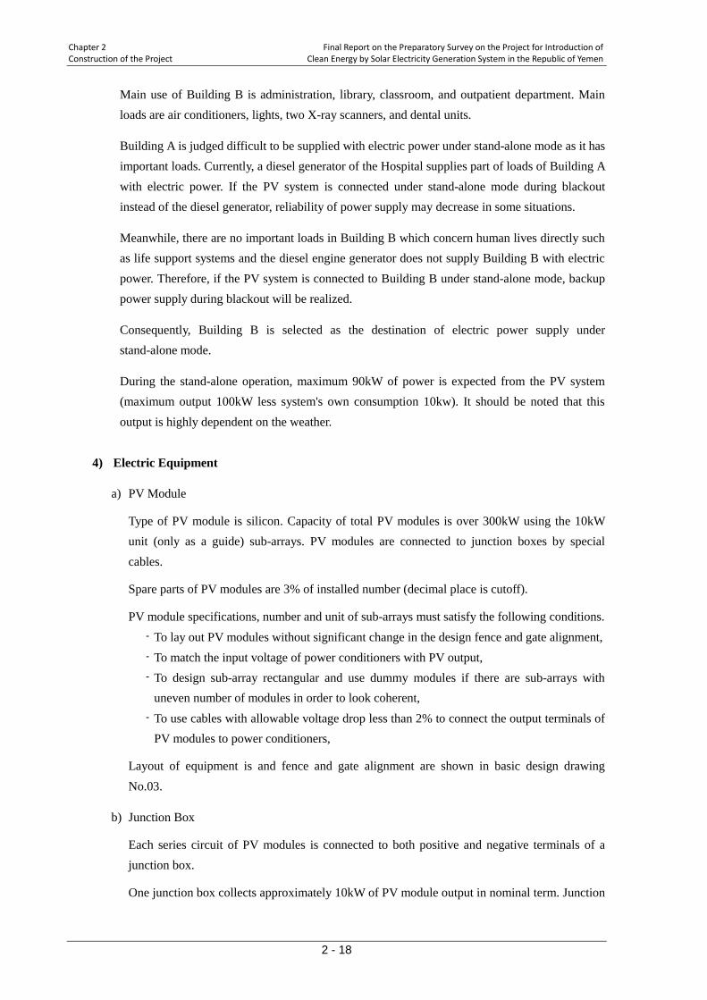
Chapter 2 Final Report on the Preparatory Survey on the Project for Introduction of Construction of the Project Clean Energy by Solar Electricity Generation System in the Republic of Yemen
2 - 18
Main use of Building B is administration, library, classroom, and outpatient department. Main loads are air conditioners, lights, two X-ray scanners, and dental units.
Building A is judged difficult to be supplied with electric power under stand-alone mode as it has important loads. Currently, a diesel generator of the Hospital supplies part of loads of Building A with electric power. If the PV system is connected under stand-alone mode during blackout instead of the diesel generator, reliability of power supply may decrease in some situations.
Meanwhile, there are no important loads in Building B which concern human lives directly such as life support systems and the diesel engine generator does not supply Building B with electric power. Therefore, if the PV system is connected to Building B under stand-alone mode, backup power supply during blackout will be realized.
Consequently, Building B is selected as the destination of electric power supply under stand-alone mode.
During the stand-alone operation, maximum 90kW of power is expected from the PV system (maximum output 100kW less system's own consumption 10kw). It should be noted that this output is highly dependent on the weather.
4) Electric Equipment
a) PV Module
Type of PV module is silicon. Capacity of total PV modules is over 300kW using the 10kW unit (only as a guide) sub-arrays. PV modules are connected to junction boxes by special cables.
Spare parts of PV modules are 3% of installed number (decimal place is cutoff).
PV module specifications, number and unit of sub-arrays must satisfy the following conditions. - To lay out PV modules without significant change in the design fence and gate alignment, - To match the input voltage of power conditioners with PV output, - To design sub-array rectangular and use dummy modules if there are sub-arrays with
uneven number of modules in order to look coherent, - To use cables with allowable voltage drop less than 2% to connect the output terminals of
PV modules to power conditioners,
Layout of equipment is and fence and gate alignment are shown in basic design drawing No.03.
b) Junction Box
Each series circuit of PV modules is connected to both positive and negative terminals of a junction box.
One junction box collects approximately 10kW of PV module output in nominal term. Junction

Final Report on the Preparatory Survey on the Project for Introduction of Chapter 2 Clean Energy by Solar Electricity Generation System in the Republic of Yemen Construction of the Project
2 - 19
boxes are equipped with a circuit breaker, anti- reverse flow diode, and arrester for each input.
c) Power Conditioner Cubicle
Outline
Power Conditioner shall consist of four main equipment shown below. These equipment shall be encased in one or a few boards. - Power Conditioner - Low Voltage Switchboard - Branch Switchers for PV Array - System Controller
All the boards shall be furnished with space heaters inside.
<Power Conditioner>
This equipment converts direct current collected from PV modules, supply the load with alternate current in connection with the utility grid power supply.
Direct current circuit is designed to operate under inflow voltage of 500V or higher.
AC circuit is designed to synchronize the PV generated power to the utility grid power by Maximum Power Point Tracking (MPPT) method.
Power Conditioners are equipped with a stand-alone function which enables providing power to limited part of the Facility, up to the power being produced by PV modules under other constraints, during the period of the power from the utility grid being suspended (blackout).
Power Conditioners shall be installed in multiple units, added by an extra stand-by unit. The stand-by unit shall be placed inside Electrical Facility Cubicle. The system shall be designed in a way that when some units are broken down, remaining unit(s) shall work within the capacity then available. This design is to ensure the maximum lifetime of the system.
<Low Voltage Switchboard>
Low Voltage Switchboard connects AC output of power conditioners to the utility grid at the low voltage side of the existing transformer via a rotable phase-adjusting transformer. It also has the distribution function to supply electric power to selected loads where individual loads can be switched by breakers.
This equipment should also be designed to have a couple of magnetic circuit breakers at grid-connection side, so as to enable both manual and automatic operations of starting stand alone mode when the main power from the utility grid is out (blackout).
An AC 3 phase arrester is installed at the grid-connection point. This equipment is also furnished with transformers and distributors for the System's own use.
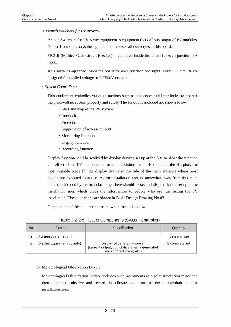
Chapter 2 Final Report on the Preparatory Survey on the Project for Introduction of Construction of the Project Clean Energy by Solar Electricity Generation System in the Republic of Yemen
2 - 20
< Branch switchers for PV arrays>
Branch Switchers for PV Array equipment is equipment that collects output of PV modules. Output from sub-arrays through collection boxes all converges at this board.
MCCB (Molded Case Circuit Breaker) is equipped inside the board for each junction box input.
An arrester is equipped inside the board for each junction box input. Main DC circuits are designed for applied voltage of DC500V or over.
<System Controller>
This equipment embodies various functions such as sequences and inter-locks, to operate the photovoltaic system properly and safely. The functions included are shown below.
- Start and stop of the PV system - Interlock - Protection - Suppression of reverse current - Monitoring function - Display function - Recording function
Display function shall be realized by display devices set up at the Site to show the function and effect of the PV equipment to users and visitors to the Hospital. In the Hospital, the most suitable place for the display device is the side of the main entrance where most people are expected to notice. As the installation area is somewhat away from this main entrance shielded by the main building, there should be second display device set up at the installation area which gives the information to people who are just facing the PV installation. These locations are shown in Basic Design Drawing No.03.
Components of this equipment are shown in the table below.
Table 2-2-2-5 List of Components (System Controller)
No. Device Specification Quantity
1 System Control Panel Complete set
2 Display Equipment(outside) Display of generating power (current output, cumulative energy generated
and CO2 reduction, etc.)
2 complete set
d) Meteorological Observation Device
Meteorological Observation Device includes such instruments as a solar irradiation meter and thermometer to observe and record the climate conditions of the photovoltaic module installation area.

Final Report on the Preparatory Survey on the Project for Introduction of Chapter 2 Clean Energy by Solar Electricity Generation System in the Republic of Yemen Construction of the Project
2 - 21
Components list
Components of this device are shown in Table 2-2-2-6.
Table 2-2-2-6 List of Components (Meteorological Observation Device) No. Component Specification Quantity
1 Pyrheliometer (Outside installation) 1
2 Thermometer (Outside installation) 1
3 Transducer (Outside storage box) For each of 1 and 2 above 2 sets
e) Low Voltage Panel (in Electrical Room No. 1)
The low voltage panel of Electrical Room No.1 will have to be replaced by this Project as the existing panel has been significantly deteriorated in function of due to the aging and corrosions which prevents safe connection of the PV system.
The Low Voltage Panel distributes electric power received from the utility power grid through the transformer to each load including the PV system. The single line diagram of the panel is shown in Drawing No.01.
Vol t-Current Transformer and Transducer (VCT) is installed inside the panel.
Vol t-Current Transformer and Transducer should be equipped to the Panel at the interconnection point in order to monitor the reverse current which is not allowed.
Outline of VCT
This device consists of VCT and a converter and sends the effective power calculated by the converter to the System Controller Equipment.
f) Branch Switchers for Load
This equipment shall function as a distributor of the loads and a switcher of two power source; utility grid power and photovoltaic power.
This board shall have a couple of breakers with mechanical inter-locking for each distribution line to load to select either the transformer or PV system for power source.
The single line diagram of Branch Switcher Board is shown in Drawing No.04
g) Electrical Facility Cubicle
Electrical Facility Cubicle of the PV System encloses the equipment below the cubicle is furnished with air conditioning system to keep the equipment inside from overheating.
- Power Conditioner - Low Voltage Switchboard - Branch Switchers for PV Array - System Controller

Chapter 2 Final Report on the Preparatory Survey on the Project for Introduction of Construction of the Project Clean Energy by Solar Electricity Generation System in the Republic of Yemen
2 - 22
h) Support Structure for PV modules
A Support Structure for PV module sets up a sub-array of PV modules arranged in series and in parallel to attain required voltage of sending power. The Support Structure is furnished with fittings for environment monitoring instruments and Junction Boxes to be attached to the Support Structure.
The material is finished with hot dip zinc galvanizing. For the fastening used in the cradle, a countermeasure shall be taken against larceny.
Type of installation: ground installation Direction and Slope: south, 12 degrees Materials: steel Coating: Hot Dip Zinc galvanized with salinity resistance
i) Materials of Wiring and Earthing
Exterior cables are of armored type and directly buried underground. Materials of cables are copper, which has large allowable power and flexibility in installation. For insulation general-purpose cross-linked polyethylene is used.
Wiring
Exterior cable route was designed and decided, considering the information on the existing cables obtained from the Facility, confirmed in-situ with technicians and the director in charge of maintenances, so as not to interfere with the existing cables and future expansion plans of buildings, etc. Cable layout is shown in Basic Design Drawing No.05.
Following earthing fixtures are installed in this Project. Earthing
- Earthing of metal objects and electrical equipment to prevent the electric shock - Earthing of fences and gates - Independent earthing of control panels and meteorological observation devices, as
required Earthing resistance shall be less than 10 ohm.
j) Fence, Gate and Gravel Surfacing
♦ Fence and Gates
Al Wahda Hospital is surrounded by walls and there are security guards 24 hours a day which makes the risk of burglary relatively low. However, there are patients and visitors including children walking around in the hospital who must to be kept away from the PV system safely.
Therefore, the fence surrounding the PV system, with safety measures including anti-electric shock function, shall be constructed by the Project. Considering the environment in the hospital, obtrusive materials such as barb-wire should not be used.
Final Report on the Preparatory Survey on the Project for Introduction of Chapter 2 Clean Energy by Solar Electricity Generation System in the Republic of Yemen Construction of the Project
2 - 23
The alignment of the fence should be designed considering the shade it makes on PV modules, a space for maintenance works, and tamperproof from outside. Also, it should not enclose unnecessarily large plot of land to make it out of use for the facility.
There should be two sets of gates; smaller one is for everyday use of operators, the larger one for periodical maintenance allowing the entrance of motor vehicles.
Layout of fence and gates is shown in Basic Design Drawing No.03.
♦ Gravel surfacing of PV module area
PV module area should be gravel-surfaced in order to stabilize the surface, control the growth of weeds and facilitate the maintenance works. Before the placement of gravel, surface soil should be removed for approximately 10cm in depth and replaced by gravel layer. The area will be enveloped with curbstones or similar concrete blocks to keep gravels within the area. Gravels should be of the size of 20 to 40mm, strong enough to withstand the use of long years.
k) Concrete Foundation of Equipment
The foundations of supporting structures, electric facility cubicle, fences and gates are constructed.
♦ Excavation for placing foundations
There is some water related structure buried underground of the PV installation area. Unfortunately there is no definite information available. The structure is in use and must be preserved. Therefore, the excavation work at the area must be done with utmost care, employing hand excavation method as required.
♦ Foundation type
As mentioned elsewhere, there is some water related structure buried underground of the PV installation area which calls for the use of shallow foundations for the supporting structure for PV modules. Therefore, the foundations are assumed to be of U-shaped type, a horizontal member connecting two vertical members.
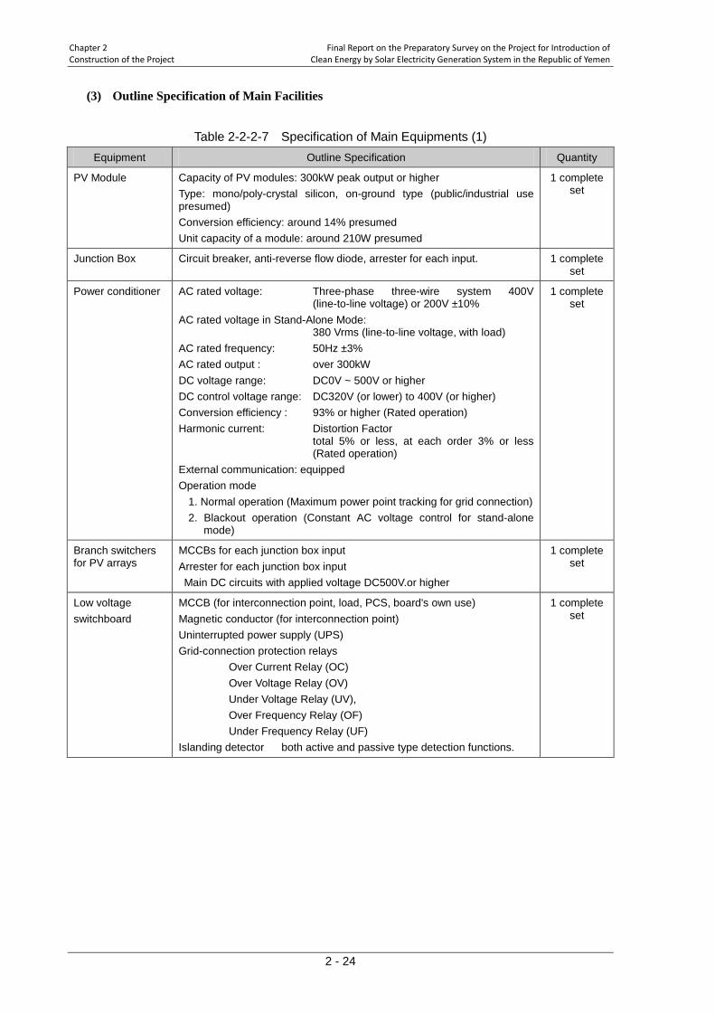
Chapter 2 Final Report on the Preparatory Survey on the Project for Introduction of Construction of the Project Clean Energy by Solar Electricity Generation System in the Republic of Yemen
2 - 24
(3) Outline Specification of Main Facilities
Table 2-2-2-7 Specification of Main Equipments (1) Equipment Outline Specification Quantity
PV Module Capacity of PV modules: 300kW peak output or higher Type: mono/poly-crystal silicon, on-ground type (public/industrial use presumed) Conversion efficiency: around 14% presumed Unit capacity of a module: around 210W presumed
1 complete set
Junction Box Circuit breaker, anti-reverse flow diode, arrester for each input. 1 complete set
Power conditioner AC rated voltage: Three-phase three-wire system 400V (line-to-line voltage) or 200V ±10%
AC rated voltage in Stand-Alone Mode: 380 Vrms (line-to-line voltage, with load)
AC rated frequency: 50Hz ±3% AC rated output : over 300kW DC voltage range: DC0V ~ 500V or higher DC control voltage range: DC320V (or lower) to 400V (or higher) Conversion efficiency : 93% or higher (Rated operation) Harmonic current: Distortion Factor
total 5% or less, at each order 3% or less (Rated operation)
External communication: equipped Operation mode
1. Normal operation (Maximum power point tracking for grid connection) 2. Blackout operation (Constant AC voltage control for stand-alone
mode)
1 complete set
Branch switchers for PV arrays
MCCBs for each junction box input Arrester for each junction box input Main DC circuits with applied voltage DC500V.or higher
1 complete set
Low voltage switchboard
MCCB (for interconnection point, load, PCS, board's own use) Magnetic conductor (for interconnection point) Uninterrupted power supply (UPS) Grid-connection protection relays Over Current Relay (OC) Over Voltage Relay (OV) Under Voltage Relay (UV), Over Frequency Relay (OF) Under Frequency Relay (UF) Islanding detector both active and passive type detection functions.
1 complete set

Final Report on the Preparatory Survey on the Project for Introduction of Chapter 2 Clean Energy by Solar Electricity Generation System in the Republic of Yemen Construction of the Project
2 - 25
Table 2-2-2-8 Specification of Main Equipments (2) Equipment Outline Specification Quantity
System controller Main functions - Start and stop of PV system - Interlock - Protection - Suppression of reverse power flow - Monitoring function - Display function - Recording function
1 complete
set
Meteorological observation device
Irradiation meter (exterior) 1 unit Thermometer (exterior) 1 unit Transducers(in storage box for exterior use) one for each of above
meters
1 complete
set
Low voltage panel MCCB Energy Meter; 2 units for receiving power
- Type: normal energy meter (testing not necessary - Three-phase three-wire system
1
complete set
Branch switchers for load (For stand-alone operation)
MCCB Mechanical interlock: 1 set
1 complete
set
Electrical facility cubicle With air conditioning (AC units shall be supplied with power from Low Voltage Switchboard either in grid-interconnection or stand-alone modes.)
1 complete
set
Support structure for PV modules
Hot dip zinc galvanized and salinity resistance fittings for meteorological devices fittings for junction boxes
1 complete
set
Materials of wiring and earthing
Wiring Form: low voltage 2-4core copper cable, XLPE insulation, PVC sheath Applicable standard: IEC Accessory: material for terminal dressing
1 complete
set
Fence, gate and gravel surfacing
Fence Height: 2m Gate Height: 2m Gravel surfacing, grain size: about 2-3cm Gravel layer thickness: 10cm or more
1 complete
set
XLPE:cross-linked polyethylene , PVC: polyvinyl chloride, MCCB: molded-case circuit breaker
2-2-3 General Drawing
Number Title
NO. 01 SINGLE LINE DIAGRAM
NO. 02 SINGLE LINE DIAGRAM (PV SYSTEM)
NO. 03 GENERAL LAYOUT PLAN
NO. 04 BRANCH SWITCHERS FOR LOAD
NO. 05 CABLE LAYOUT PLAN
NO. 06 EQUIPMENTS LAYOUT (NO. 1 ELECTRIC ROOM)
NO. 07 EQUIPMENTS LAYOUT (BUILDING B ELECTRIC ROOM)
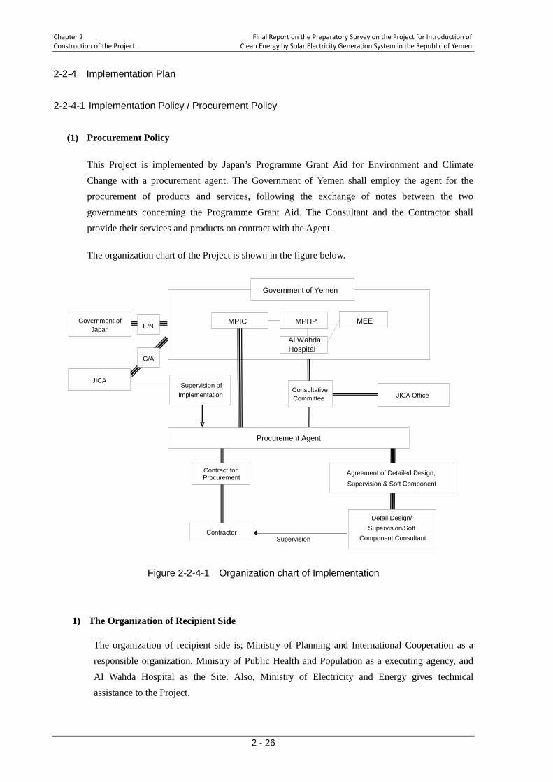
Chapter 2 Final Report on the Preparatory Survey on the Project for Introduction of Construction of the Project Clean Energy by Solar Electricity Generation System in the Republic of Yemen
2 - 26
2-2-4 Implementation Plan 2-2-4-1 Implementation Policy / Procurement Policy
(1) Procurement Policy
This Project is implemented by Japan’s Programme Grant Aid for Environment and Climate Change with a procurement agent. The Government of Yemen shall employ the agent for the procurement of products and services, following the exchange of notes between the two governments concerning the Programme Grant Aid. The Consultant and the Contractor shall provide their services and products on contract with the Agent.
The organization chart of the Project is shown in the figure below.
Figure 2-2-4-1 Organization chart of Implementation
1) The Organization of Recipient Side
The organization of recipient side is; Ministry of Planning and International Cooperation as a responsible organization, Ministry of Public Health and Population as a executing agency, and Al Wahda Hospital as the Site. Also, Ministry of Electricity and Energy gives technical assistance to the Project.
Supervision
Government of Yemen
Government of Japan
JICA
Procurement Agent
E/N
Supervision of Implementation
Contractor Detail Design/
Supervision/Soft
Agreement of Detailed Design, Supervision & Soft Component
MPIC
Contract for Procurement
G/A
Component Consultant
MEE
Al Wahda Hospital
MPHP
JICA Office Consultative Committee
Final Report on the Preparatory Survey on the Project for Introduction of Chapter 2 Clean Energy by Solar Electricity Generation System in the Republic of Yemen Construction of the Project
2 - 27
2) The Procurement Agent
On Japan's side, it is the procurement agent who will make into the agent agreement with the recipient to undertake tendering, contracting and manage the whole procurement business. In addition the agent will implement the settlement for consultants and the contractor and fund administration on behalf of Recipient side.
3) Consultants
The Consultant will assist the procurement agent in his undertaking of tendering, supervise the works of the Contractor, issue certificates for taking over after the completion of procurement/installation works and for the end of defect liability scheduled one year after the taking over. He also will provide training to people concerned so that the equipment will be properly operated and managed.
4) The Contractor
The Contractor, according to the contract made into with the Agent, designs, manufactures and transports the products, installs and commissions the products, and gives guidance to operators for the operation and maintenance of the products. From a perspective of quality and reasonable implementing policy, the Contractor will implement the procurement of equipment and installation on the package.
(2) Implementation Policy
For installation works, local contractors will be able to handle the works under Japanese prime contractor. The main works for the Project are; civil works (earthworks and concrete foundation works), steel works (assembling of support structure of PV modules) and electrical works (electrical wirings and installation of solar modules and other equipment).
In principle, Japanese standards are applicable in this Project since the PV system is one of the first of its kind to be built in Yemen. However, adequate methods normally used in the country may be utilized for the installation works.
In principle, the construction methods normally practiced in the Yemen can be utilized for the installation works. Local contractors will be utilized as much as possible in the works under Japanese prime contractor. It is difficult to reduce the number of Japanese engineers if the Contractor is to keep both the quality of works that meets the required standards in the Japanese grant aid projects, and with a suitable management. However, the number of engineers can be as small as possible, without compromising with the quality of the work, by adopting the local standards for the design and specification where possible.
Chapter 2 Final Report on the Preparatory Survey on the Project for Introduction of Construction of the Project Clean Energy by Solar Electricity Generation System in the Republic of Yemen
2 - 28
2-2-4-2 Procurement/Installation Conditions
(1) Construction Business in the Recipient Country
Although there is no local company that has engaged in PV projects with large capacity, some electrical contractors such as the ones from Dubai have experiences of the similar large-scale electrical project and have their office in Aden. These contractors are expected to be able to handle works that meet the required standards in Japanese Grant Aid programmes.
There are some companies dealing with rental of construction machines in Aden, and it is confirmed that the machines necessary for the Project can be hired from those companies.
(2) Installation Conditions
Considering the climate at the Site and the types of installation, extra care must be taken during the installation works, as follows.
- The climate in Aden is characterized by high temperature with low humidity throughout the year and the maximum temperature reaches beyond 40 degrees between May and July. Therefore, for the hot season, installation works especially concrete works should be given special attention, possibly avoiding these works.
- Some underground structures have been identified at the PV installation area. However, the detailed information such as the exact locations and the depths are unknown since the drawings are unavailable. Therefore, shallow foundations will be used, and extra attention should be paid during the earthwork in order not to damage the existing underground structures.
- As the Site is in a hospital, keeping good communication, especially about the schedule and the contents of the works, with the hospital side is important, especially when the electricity in the hospital has to be cut off for the works such as electrical rooms and distribution boards. The timing and duration of the cut off should be considered in drawing up the schedule. Also, if the electricity from the utility grid is expected to be cut off for a prolonged period, alternative source of power such as the use of diesel generators must be considered to shorten the periods of power-less situation.
2-2-4-3 Scope of Work
The work demarcation between the Japanese and the Yemen sides is as follows.
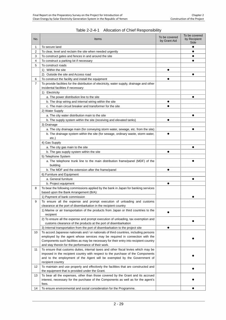
Final Report on the Preparatory Survey on the Project for Introduction of Chapter 2 Clean Energy by Solar Electricity Generation System in the Republic of Yemen Construction of the Project
2 - 29
Table 2-2-4-1 Allocation of Chief Responsibility
No. Items To be covered by Grant Aid
To be covered by Recipient
Side 1 To secure land 2 To clear, level and reclaim the site when needed urgently 3 To construct gates and fences in and around the site 4 To construct a parking lot if necessary 5 To construct roads 1) Within the site 2) Outside the site and Access road 6 To construct the facility and install the equipment 7 To provide facilities for the distribution of electricity, water supply, drainage and other
incidental facilities if necessary:
1) Electricity a. The power distribution line to the site b. The drop wiring and internal wiring within the site c. The main circuit breaker and transformer for the site 2) Water Supply a. The city water distribution main to the site b. The supply system within the site (receiving and elevated tanks) 3) Drainage a. The city drainage main (for conveying storm water, sewage, etc. from the site) b. The drainage system within the site (for sewage, ordinary waste, storm water,
etc.)
4) Gas Supply a. The city gas main to the site b. The gas supply system within the site 5) Telephone System a. The telephone trunk line to the main distribution frame/panel (MDF) of the
building
b. The MDF and the extension after the frame/panel 6) Furniture and Equipment a. General furniture b. Project equipment 8 To bear the following commissions applied by the bank in Japan for banking services
based upon the Bank Arrangement (B/A):
1) Payment of bank commission 9 To ensure all the expense and prompt execution of unloading and customs
clearance at the port of disembarkation in the recipient country
1) Marine or air transportation of the products from Japan or third countries to the recipient
2) To ensure all the expense and prompt execution of unloading, tax exemption and customs clearance of the products at the port of disembarkation
3) Internal transportation from the port of disembarkation to the project site 10 To accord Japanese nationals and / or nationals of third countries, including persons
employed by the agent whose services may be required in connection with the Components such facilities as may be necessary for their entry into recipient country and stay therein for the performance of their work.
11 To ensure that customs duties, internal taxes and other fiscal levies which may be imposed in the recipient country with respect to the purchase of the Components and to the employment of the Agent will be exempted by the Government of recipient country
12 To maintain and use properly and effectively the facilities that are constructed and the equipment that is provided under the Grant.
13 To bear all the expenses, other than those covered by the Grant and its accrued interest, necessary for the purchase of the Components as well as for the agent’s fees.
14 To ensure environmental and social consideration for the Programme.
Chapter 2 Final Report on the Preparatory Survey on the Project for Introduction of Construction of the Project Clean Energy by Solar Electricity Generation System in the Republic of Yemen
2 - 30
2-2-4-4 Consultant Supervision This Project will be started according to the rules of Japan's Programme Grant Aid, after the exchange of notes (E/N) between the two countries which follows the design carefully considered on the basis of the basic design, and its assessment for the appropriateness by the Government of Japan. During the installation works, synchronized with the progress of civil and electric works, the Consultant will send at least one resident engineer for the management of schedule, quality and safety of the Works. The Consultant also witnesses shop and pre-shipment inspections of equipments and materials procured in Japan to avoid any problems from happening, which may appear after the equipment from Japan have arrived at the Site.
(1) Basic Policy on Supervision of the Installation Works
The Consultant shall look after the progress of the works and ensure that the works be finished within a given time-frame. He shall also supervise and guide the Contractor to ensure both the quality of the Works as the Contract Documents stipulate, and the safety of the Works. To attain this objective, the Consultant sends two construction supervisors, one an electric equipment specialist and the other a civil engineer, to the Site coordinated with the progress of the Works.
The main important points in installation work supervision are shown below.
1) Schedule Control
The consultant will compare the implementation schedule originally prepared by the prime Contractor with the progress of the work in terms of the following items every month and every week. If the progress of the work is considered behind the original schedule, the consultant will issue warning and request remedy plans to the Contractor to complete the installation works within a given time-frame.
- confirmation of quantity of work done, - confirmation of arrivals of equipment and materials, - comparison between planned and actual turn-out of engineers, technicians and laborers.
2) Quality Control
The consultant will carry out the following inspections to determine whether the qualities of the equipment stipulated in the Contract Documents (Technical Specifications, Drawings) are secured by the Contractor. If the qualities of the works are questionable, the Consultant will request the Contractor remedies, changes and/or adjustments.
- checking shop drawings and specifications of the equipment and materials, - witnessing shop inspection or verifying the test reports, - checking installation procedure statement, site test, adjustment and site inspection
procedure statement, and shop drawings, - supervising the installation work and witnessing test run, adjustment and inspection,
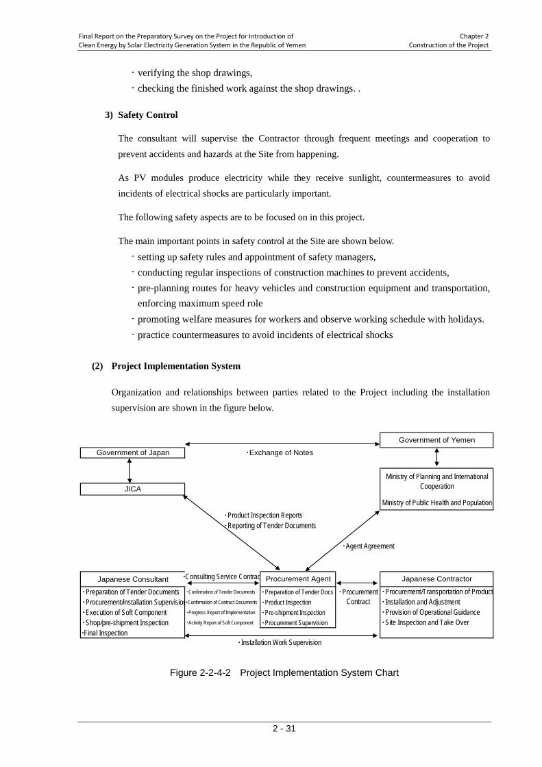
Final Report on the Preparatory Survey on the Project for Introduction of Chapter 2 Clean Energy by Solar Electricity Generation System in the Republic of Yemen Construction of the Project
2 - 31
- verifying the shop drawings, - checking the finished work against the shop drawings. .
3) Safety Control
The consultant will supervise the Contractor through frequent meetings and cooperation to prevent accidents and hazards at the Site from happening.
As PV modules produce electricity while they receive sunlight, countermeasures to avoid incidents of electrical shocks are particularly important.
The following safety aspects are to be focused on in this project.
The main important points in safety control at the Site are shown below.
- setting up safety rules and appointment of safety managers, - conducting regular inspections of construction machines to prevent accidents, - pre-planning routes for heavy vehicles and construction equipment and transportation,
enforcing maximum speed role - promoting welfare measures for workers and observe working schedule with holidays. - practice countermeasures to avoid incidents of electrical shocks
(2) Project Implementation System
Organization and relationships between parties related to the Project including the installation supervision are shown in the figure below.
Figure 2-2-4-2 Project Implementation System Chart
Ministry of Public Health and Population▪Product Inspection Reports▪Reporting of Tender Documents
▪Agent Agreement
Japanese Consultant ▪Consulting Service Contrac
▪Preparation of Tender Documents ▪Confirmation of Tender Documents ▪Preparation of Tender Docs▪Procurement/installation Supervision▪Confirmation of Contract Documents ▪Product Inspection▪Execution of Soft Component ▪Progress Report of Implementation ▪Pre-shipment Inspection▪Shop/pre-shipment Inspection ▪Activity Report of Soft Component ▪Procurement Supervision▪Final Inspection
Japanese Contractor
Government of Japan
Government of Yemen
▪Exchange of Notes
JICA
▪Installation Work Supervision
Ministry of Planning and InternationalCooperation
▪ProcurementContract
▪Procurement/Transportation of Product▪Installation and Adjustment▪Provision of Operational Guidance▪Site Inspection and Take Over
Procurement Agent
Chapter 2 Final Report on the Preparatory Survey on the Project for Introduction of Construction of the Project Clean Energy by Solar Electricity Generation System in the Republic of Yemen
2 - 32
2-2-4-5 Quality Control Plan The Installation work supervisor of the Consultant conducts the supervision by the items shown below to confirm whether the quality of equipment and installation satisfies the relevant stipulations in the Contract Documents (Technical Specifications and Drawings, etc.). If the qualities of the works are questionable, the Consultant will request the Contractor remedies, changes and/or adjustments.
- checking shop drawings and specifications of the equipment and materials, - witnessing shop inspection or verifying the test reports, - checking installation procedure statement, site test, adjustment and site inspection
procedure statement, and shop drawings, - supervising the installation work and witnessing test run, adjustment and inspection,
verifying the shop drawings, checking the finished work against the shop drawings. . 2-2-4-6 Procurement Plan
(1) Procurement in Japan
Among various items of the Products to be procured in the Project, PV modules and power conditioners shall be of made in Japan.
(2) Transportation Plan
The PV related electric equipment and materials procured in Japan will arrive at the biggest port in Yemen, Aden Port. The port is an international port which covers an area some 14.5km east-west and 5.6km north-south with the depth of between 5m and 16m. The maximum capacity of bulk silos are 50,000ton. The maximum capacity of the mobile crane is 50ton, which are well beyond the needed capacity of 20ton for this Project. The target site, Al-Wahda Hospital, is located relatively near to the port, about 10km. Also, there are many experienced transport companies in Aden and the access roads from the port to the Hospital are well maintained. Therefore, there is no concern related to the local transport of the materials from Japan.
2-2-4-7 Operational Guidance Plan
(1) Objectives
Operational Guidance shall be given to those engineers and technicians who will be in charge of operation and maintenance of the PV system so that the system, which is the first case of this size, will be operated and maintained properly, even under emergency situations.
There has been no experience and knowledge of grid-connection of renewable resources such as
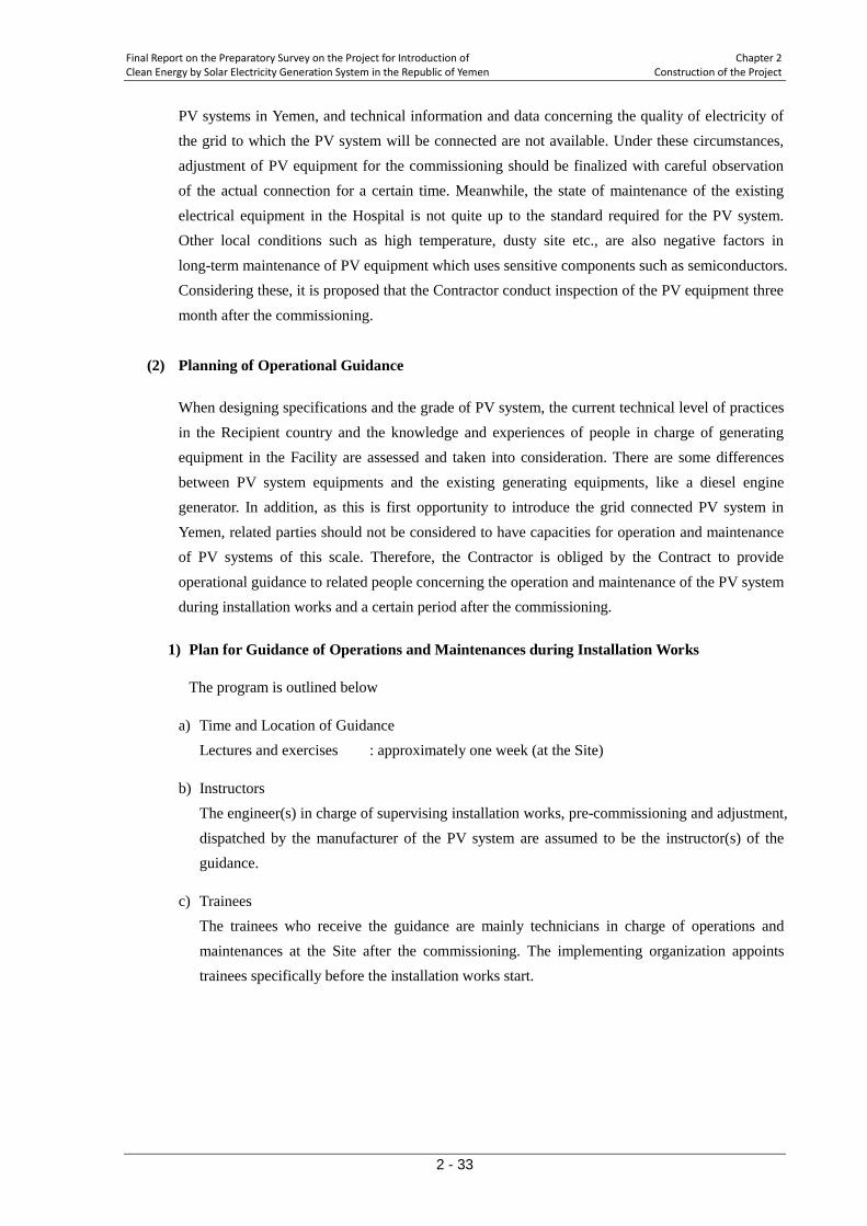
Final Report on the Preparatory Survey on the Project for Introduction of Chapter 2 Clean Energy by Solar Electricity Generation System in the Republic of Yemen Construction of the Project
2 - 33
PV systems in Yemen, and technical information and data concerning the quality of electricity of the grid to which the PV system will be connected are not available. Under these circumstances, adjustment of PV equipment for the commissioning should be finalized with careful observation of the actual connection for a certain time. Meanwhile, the state of maintenance of the existing electrical equipment in the Hospital is not quite up to the standard required for the PV system. Other local conditions such as high temperature, dusty site etc., are also negative factors in long-term maintenance of PV equipment which uses sensitive components such as semiconductors. Considering these, it is proposed that the Contractor conduct inspection of the PV equipment three month after the commissioning.
(2) Planning of Operational Guidance
When designing specifications and the grade of PV system, the current technical level of practices in the Recipient country and the knowledge and experiences of people in charge of generating equipment in the Facility are assessed and taken into consideration. There are some differences between PV system equipments and the existing generating equipments, like a diesel engine generator. In addition, as this is first opportunity to introduce the grid connected PV system in Yemen, related parties should not be considered to have capacities for operation and maintenance of PV systems of this scale. Therefore, the Contractor is obliged by the Contract to provide operational guidance to related people concerning the operation and maintenance of the PV system during installation works and a certain period after the commissioning.
1) Plan for Guidance of Operations and Maintenances during Installation Works
The program is outlined below
a) Time and Location of Guidance Lectures and exercises : approximately one week (at the Site)
b) Instructors The engineer(s) in charge of supervising installation works, pre-commissioning and adjustment, dispatched by the manufacturer of the PV system are assumed to be the instructor(s) of the guidance.
c) Trainees The trainees who receive the guidance are mainly technicians in charge of operations and maintenances at the Site after the commissioning. The implementing organization appoints trainees specifically before the installation works start.
Chapter 2 Final Report on the Preparatory Survey on the Project for Introduction of Construction of the Project Clean Energy by Solar Electricity Generation System in the Republic of Yemen
2 - 34
Table 2-2-4-2 Organization Control of Operations and Maintenances Person in charge number Main role Control technician 1 Responsible official and decision making
Operation
Electric technician 1 Management of PV system based on technical
knowledge of electric equipment and PV system Electric
technician About 2 Normal operation
Maintenance
Electric technician 1 Handling of PV system in troubles based on technical
knowledge of electric equipment and PV system Electric
technician 2 Daily inspection
Sanitation worker
Few persons Cleaning of PV modules
d) Contents of Guidance
i) Lectures
Using Operation and Maintenance Manuals, lectures on basic knowledge of the PV system will be given.
- Explanation of Operation and Maintenance Manuals - Basic Knowledge of Operation and Maintenance (operation scheduling, control,
basic knowledge of preventive maintenance, functions of the system, basic knowledge of malfunctions and their handling, spare parts and tools, management of drawing and documents)
ii) Exercises at the Site
During the period of installation works and pre-commissioning, following items will be taught at the Site.
- Methods of start up and shut down of the system - Explanations on meters on the boards and parts - Methods of emergency shutdown of the system - Methods and subjects of observations and inspections - Methods of cleaning of cables, etc. - Methods of maintenance of electric equipment (including cleaning of PV modules)
2-2-4-8 Proposal on Training Program
(1) Background
For Yemen, this Project will be the first-ever experience to have a PV system with grid interconnection, although Yemen has a number of cases of independent off-grid solar systems, those for medical facilities and schools, etc. Therefore, it is important to train those Al Wahda hospital technicians who will be actually operating and maintaining the equipment. At the same

Final Report on the Preparatory Survey on the Project for Introduction of Chapter 2 Clean Energy by Solar Electricity Generation System in the Republic of Yemen Construction of the Project
2 - 35
time, it is also important to inform officers in the Ministry of Electricity and PEC, and other people who will be involved in the Project, regarding the technical features and institutional issues relevant to PV systems and their interconnection to the utility grid, to prepare them to handle renewable projects in the future.
Operational guidance provided by the Contractor, as explained in the previous section, aims to furnish operators at the Site with practical methods of operation and maintenance of the PV system. On the other hand, the training program discussed here is planned with the objectives to transfer technical knowledge behind the operation methods, building a foundation among the operators and other people concerned for better judgment and application of basic knowledge in the various situations of the management of the PV system, with expectations of development in future projects of a similar kind.
In particular, as the PV system is designed to be equipped with "stand-alone function" to supply power to part of the facility during blackouts, the program should put some emphasis on the importance of understanding of the limitations and issues of the function for proper use of the function.
Further, as pointed out in 2-2-4-7, due to lack of experience of grid connection of renewable power in the country and that of technical data concerning quality of grid power, it is proposed that the Contractor conduct an inspection three month after the commissioning. The second series of training program will be carried out at the same time, in order to reinforce the training and ensure consolidation and sustainability of the knowledge transferred.
(2) Objectives of Training Program
The aims are to enable the receipt country stakeholders to do things as shown below.
For operations and maintenances technicians at the Site;
- To operate and maintain PV system under normal and emergency conditions, with sufficient knowledge of the function of PV system in connection with the existing electric equipment in the facility,
- To deal with the daily and periodical inspection and maintenance, fully understanding their meaning and importance, and also to change and procure the spare parts and consumables,
- To consider routine activities of operation and maintenance and prepare an operation and maintenance management plan,
- To manage selection and arrangement of electric equipment at the destination of "stand-alone mode" power.
- To have basic knowledge that empowers them to give trainings to novice operators within and outside the facility,
- To explain the system to the visitors using publicity leaflets prepared in the program.
Chapter 2 Final Report on the Preparatory Survey on the Project for Introduction of Construction of the Project Clean Energy by Solar Electricity Generation System in the Republic of Yemen
2 - 36
For officials in governments and electric utility company - To understand the PV system theories, technical characteristics, and institutional issues, - To have technical knowledge relevant in preparing agreements between private owners of
power generators and the electric utility company,
- To acquire the knowledge for the development and guidance of new operations and maintenances staff,
- To promote the use of PV using the publicity leaflets prepared in the program.
(3) Outcome of Training Programs
- The operation and maintenance management plan has been established, and the PV system procured is operated and maintained autonomously and sustainably,
- The stand-alone function is used properly with the adequate arrangement of electric equipment at the destination,
- Technical officers at the Ministry of Electricity and PEC are equipped with knowledge on the method of planning and on the institutional provisions for interconnection of renewable power generation systems,
- Use of PV is being promoted using the publicity leaflets prepared in the program.
(4) Confirmation and Evaluation of Outcomes
Most tangible outcome will be the operation and maintenance management plan. As discussed below, the training programs are divided into two periods, the first during the commissioning of the equipment and the other three months after the commissioning. The operation and maintenance management plan will be drafted in the first-period program and revised in the second, taking into account the actual experiences in three months. Publicity Leaflet will be designed and prepared in the programs, with due consideration to the current status of renewable energy use in the recipient country, to be used and distributed to public in order to introduce the PV system procured in the Project and to promote the use of renewable energy.
Other outcomes in the first-period program will be evaluated in the following manners at the beginning of the second-period program. The whole program will also be evaluated with the materials presented at the Work Shop to be held at the end of the programs, further supplemented by questionnaires.
- Evaluation of operation records and daily check sheets for three months, - Evaluation of problem-response records for three months, - Evaluation of communication and discussions in Trouble Shooting sessions in the
second-period program, - Evaluation of knowledge acquisition concerning the system-wide management, through
Exercises, Workshop and its handouts prepared, - A questionnaire conducted at end of the training programs
Final Report on the Preparatory Survey on the Project for Introduction of Chapter 2 Clean Energy by Solar Electricity Generation System in the Republic of Yemen Construction of the Project
2 - 37
(5) Planning of Training Program
1) Content
Training program is planned to consist of a series of lectures, exercises, and OJTs led by Japanese consultants. The program is to be carried out in two separate periods; one during the commissioning of the equipment, and the other three months after the commissioning.
There will also be an operational guidance provided by the Contractor. During this period, the consultant will coordinate with the Contractor and plan the details of his training program so that the necessary techniques and knowledge are effectively transferred to the participants of the program. Those training items with a symbol (*) below are the ones presumably provided by the Contractor. The consultants will provide additional information for such items, if necessary, to make them more relevant, not just "how to operate", in the context of understanding of PV systems.
Lectures on basic knowledge
Before commissioning (approximately starting 4 weeks before commissioning)
- Basic theory of photovoltaic generation - Utilization of photovoltaic generation - Grid-interconnection and its planning - Understanding surplus and reverse current - Supply of power to the facility from the grid - Power demand and loads in the facility - Workings of PV equipment during blackout - Stand-alone operation and protection functions - Load management at the destination of Stand-alone mode power - Planning PV systems - Arrangement between PV owner and power utility
Lectures on construction planning
- Installation of PV system - Power distribution in the facility (with exercises) - Electric equipment in the facility and connection of PV system - Scheduling works - Work supervision and inspection, take-over
OJT program
- Witnessing connection works - Witnessing pre-commissioning/commissioning tests
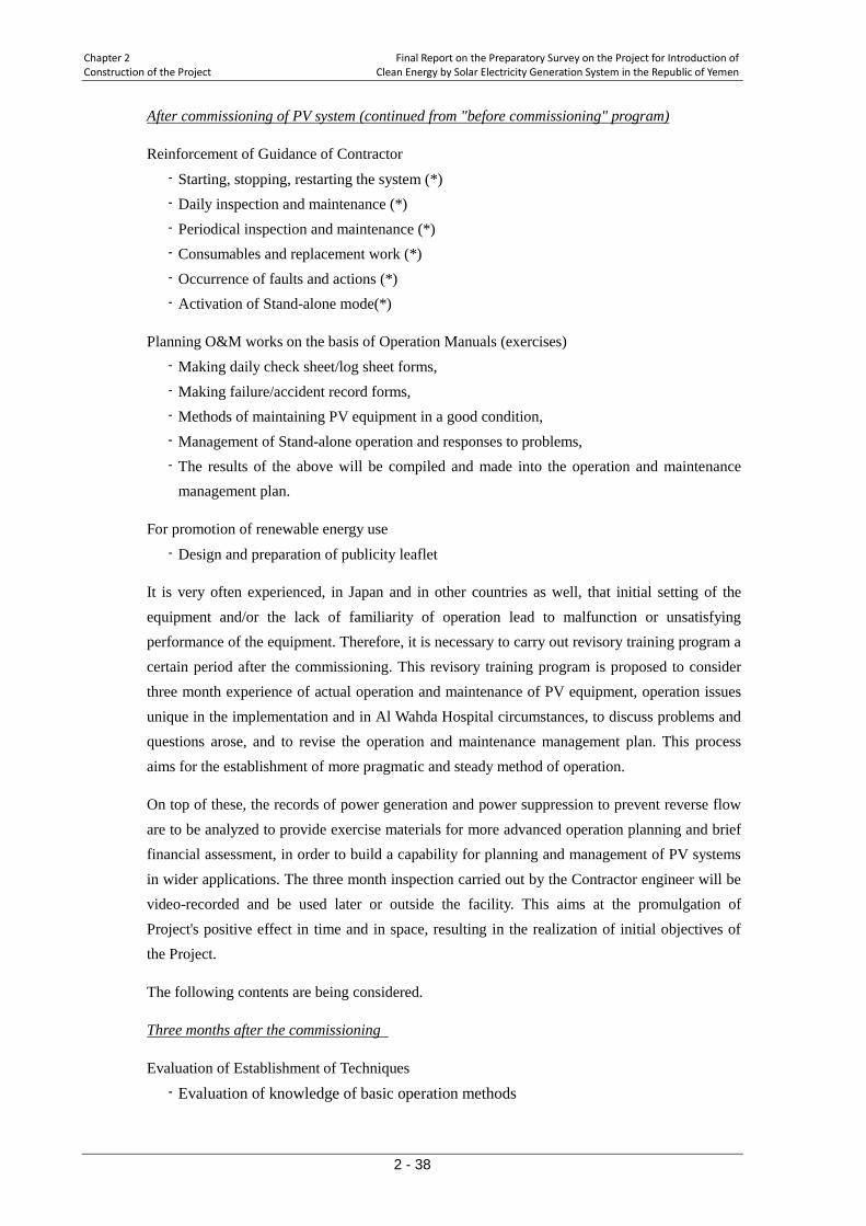
Chapter 2 Final Report on the Preparatory Survey on the Project for Introduction of Construction of the Project Clean Energy by Solar Electricity Generation System in the Republic of Yemen
2 - 38
Reinforcement of Guidance of Contractor
After commissioning of PV system (continued from "before commissioning" program)
- Starting, stopping, restarting the system (*) - Daily inspection and maintenance (*) - Periodical inspection and maintenance (*) - Consumables and replacement work (*) - Occurrence of faults and actions (*) - Activation of Stand-alone mode(*)
Planning O&M works on the basis of Operation Manuals (exercises) - Making daily check sheet/log sheet forms, - Making failure/accident record forms, - Methods of maintaining PV equipment in a good condition, - Management of Stand-alone operation and responses to problems, - The results of the above will be compiled and made into the operation and maintenance
management plan.
For promotion of renewable energy use
- Design and preparation of publicity leaflet
It is very often experienced, in Japan and in other countries as well, that initial setting of the equipment and/or the lack of familiarity of operation lead to malfunction or unsatisfying performance of the equipment. Therefore, it is necessary to carry out revisory training program a certain period after the commissioning. This revisory training program is proposed to consider three month experience of actual operation and maintenance of PV equipment, operation issues unique in the implementation and in Al Wahda Hospital circumstances, to discuss problems and questions arose, and to revise the operation and maintenance management plan. This process aims for the establishment of more pragmatic and steady method of operation.
On top of these, the records of power generation and power suppression to prevent reverse flow are to be analyzed to provide exercise materials for more advanced operation planning and brief financial assessment, in order to build a capability for planning and management of PV systems in wider applications. The three month inspection carried out by the Contractor engineer will be video-recorded and be used later or outside the facility. This aims at the promulgation of Project's positive effect in time and in space, resulting in the realization of initial objectives of the Project.
The following contents are being considered.
Evaluation of Establishment of Techniques
Three months after the commissioning
- Evaluation of knowledge of basic operation methods
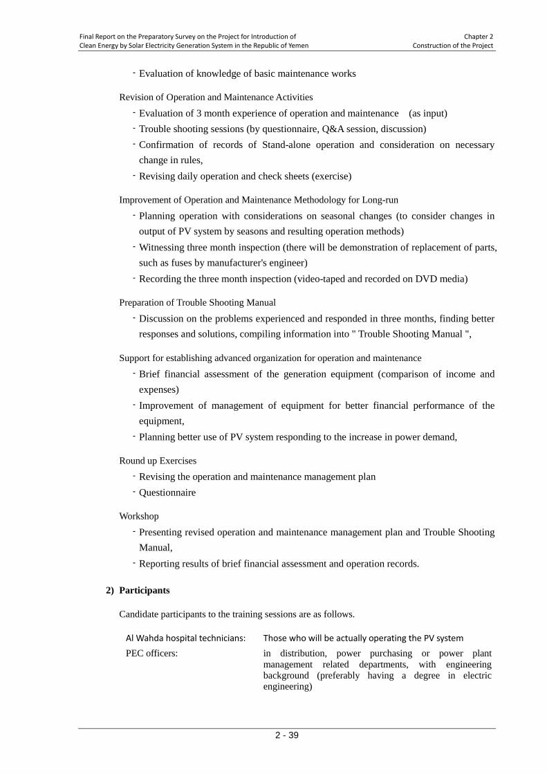
Final Report on the Preparatory Survey on the Project for Introduction of Chapter 2 Clean Energy by Solar Electricity Generation System in the Republic of Yemen Construction of the Project
2 - 39
- Evaluation of knowledge of basic maintenance works
Revision of Operation and Maintenance Activities
- Evaluation of 3 month experience of operation and maintenance (as input) - Trouble shooting sessions (by questionnaire, Q&A session, discussion) - Confirmation of records of Stand-alone operation and consideration on necessary
change in rules, - Revising daily operation and check sheets (exercise)
Improvement of Operation and Maintenance Methodology for Long-run
- Planning operation with considerations on seasonal changes (to consider changes in output of PV system by seasons and resulting operation methods)
- Witnessing three month inspection (there will be demonstration of replacement of parts, such as fuses by manufacturer's engineer)
- Recording the three month inspection (video-taped and recorded on DVD media)
Preparation of Trouble Shooting Manual
- Discussion on the problems experienced and responded in three months, finding better responses and solutions, compiling information into " Trouble Shooting Manual ",
Support for establishing advanced organization for operation and maintenance
- Brief financial assessment of the generation equipment (comparison of income and expenses)
- Improvement of management of equipment for better financial performance of the equipment,
- Planning better use of PV system responding to the increase in power demand,
Round up Exercises
- Revising the operation and maintenance management plan - Questionnaire
Workshop
- Presenting revised operation and maintenance management plan and Trouble Shooting Manual,
- Reporting results of brief financial assessment and operation records.
2) Participants
Candidate participants to the training sessions are as follows.
Al Wahda hospital technicians: Those who will be actually operating the PV system
PEC officers: in distribution, power purchasing or power plant management related departments, with engineering background (preferably having a degree in electric engineering)
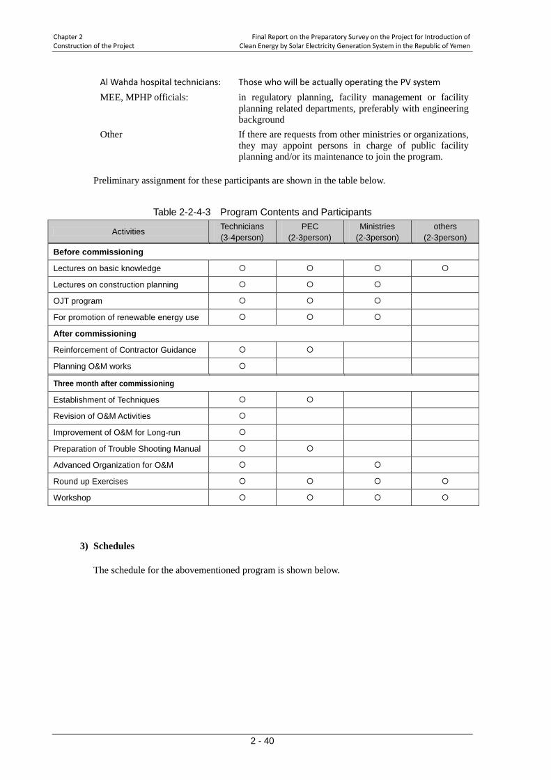
Chapter 2 Final Report on the Preparatory Survey on the Project for Introduction of Construction of the Project Clean Energy by Solar Electricity Generation System in the Republic of Yemen
2 - 40
Al Wahda hospital technicians: Those who will be actually operating the PV system
MEE, MPHP officials: in regulatory planning, facility management or facility planning related departments, preferably with engineering background
Other If there are requests from other ministries or organizations, they may appoint persons in charge of public facility planning and/or its maintenance to join the program.
Preliminary assignment for these participants are shown in the table below.
Table 2-2-4-3 Program Contents and Participants
Activities Technicians (3-4person)
PEC (2-3person)
Ministries (2-3person)
others (2-3person)
Before commissioning
Lectures on basic knowledge
Lectures on construction planning
OJT program
For promotion of renewable energy use
After commissioning
Reinforcement of Contractor Guidance
Planning O&M works
Three month after commissioning
Establishment of Techniques
Revision of O&M Activities
Improvement of O&M for Long-run
Preparation of Trouble Shooting Manual
Advanced Organization for O&M
Round up Exercises
Workshop
3) Schedules
The schedule for the abovementioned program is shown below.
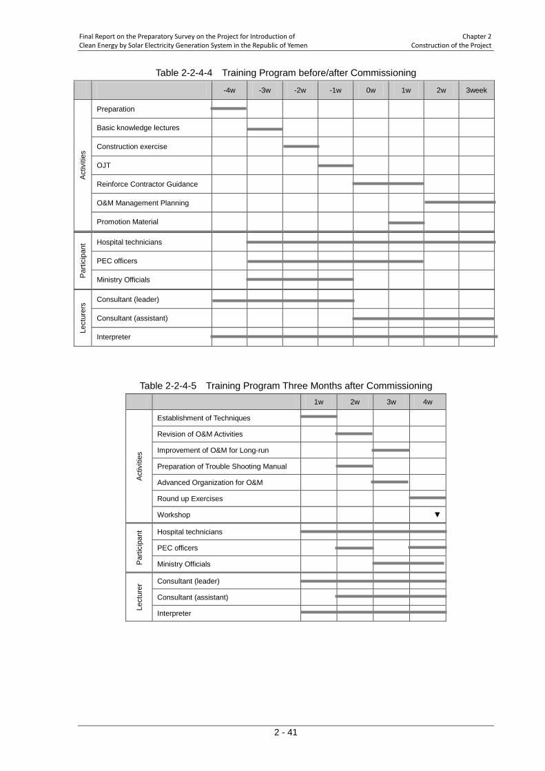
Final Report on the Preparatory Survey on the Project for Introduction of Chapter 2 Clean Energy by Solar Electricity Generation System in the Republic of Yemen Construction of the Project
2 - 41
Table 2-2-4-4 Training Program before/after Commissioning
-4w -3w -2w -1w 0w 1w 2w 3week A
ctiv
ities
Preparation
Basic knowledge lectures
Construction exercise
OJT
Reinforce Contractor Guidance
O&M Management Planning
Promotion Material
Par
ticip
ant Hospital technicians
PEC officers
Ministry Officials
Lect
urer
s Consultant (leader)
Consultant (assistant)
Interpreter
Table 2-2-4-5 Training Program Three Months after Commissioning 1w 2w 3w 4w
Act
iviti
es
Establishment of Techniques
Revision of O&M Activities
Improvement of O&M for Long-run
Preparation of Trouble Shooting Manual
Advanced Organization for O&M
Round up Exercises
Workshop ▼
Par
ticip
ant Hospital technicians
PEC officers
Ministry Officials
Lect
urer
Consultant (leader)
Consultant (assistant)
Interpreter
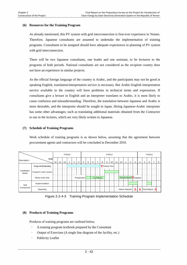
Chapter 2 Final Report on the Preparatory Survey on the Project for Introduction of Construction of the Project Clean Energy by Solar Electricity Generation System in the Republic of Yemen
2 - 42
(6) Resources for the Training Program
As already mentioned, this PV system with grid interconnection is first-ever experience in Yemen. Therefore, Japanese consultants are assumed to undertake the implementation of training programs. Consultants to be assigned should have adequate experiences in planning of PV system with grid interconnection.
There will be two Japanese consultants, one leader and one assistant, to be lecturers to the programs of both periods. National consultants are not considered as the recipient country does not have an experience in similar projects.
As the official foreign language of the country is Arabic, and the participants may not be good at speaking English, translation/interpretation service is necessary. But Arabic-English interpretation service available in the country will have problems in technical terms and expressions. If consultants give a lecture in English and an interpreter translates to Arabic, it is most likely to cause confusion and misunderstanding. Therefore, the translation between Japanese and Arabic is more desirable, and the interpreter should be sought in Japan. Hiring Japanese-Arabic interpreter has some other advantages; such as translating additional materials obtained from the Contractor to use in the lectures, which are very likely written in Japanese.
(7) Schedule of Training Programs
Work schedule of training programs is as shown below, assuming that the agreement between procurement agents and contractors will be concluded in December 2010.
Figure 2-2-4-3 Training Program Implementation Schedule
(8) Products of Training Programs
Products of training programs are outlined below.
- A training program textbook prepared by the Consultant - Output of Exercises (A single line diagram of the facility, etc.) - Publicity Leaflet
DescriptionMonth
Factory Test
Transport & Custom Clearance
Preparation Completion
Implementation
Reporting Interim Reports Final Report
Works at the Site
SoftComponent
InstallationWorks
Design and Manufacturing
FY2011 FY2012FY2010
10 11 12 6 7 61 2 8 9 10 113 4 5 2 3 4 512 1 7 8
Civil Works Electric Works
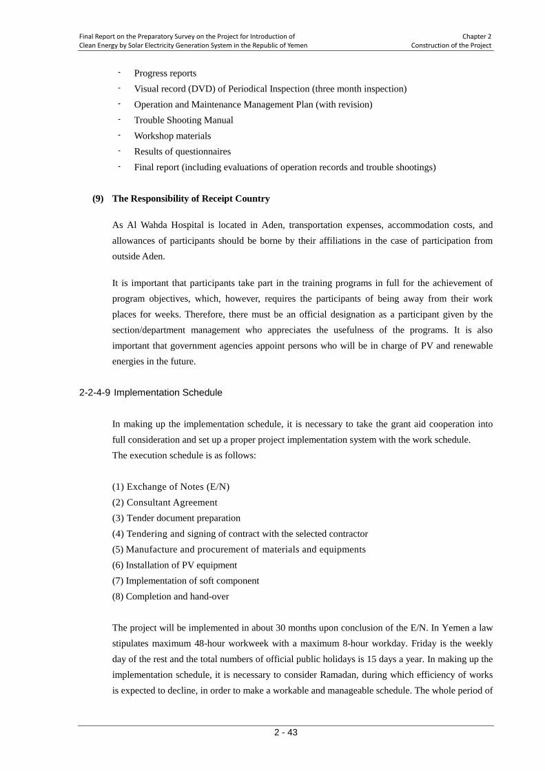
Final Report on the Preparatory Survey on the Project for Introduction of Chapter 2 Clean Energy by Solar Electricity Generation System in the Republic of Yemen Construction of the Project
2 - 43
- Progress reports - Visual record (DVD) of Periodical Inspection (three month inspection) - Operation and Maintenance Management Plan (with revision) - Trouble Shooting Manual - Workshop materials - Results of questionnaires - Final report (including evaluations of operation records and trouble shootings)
(9) The Responsibility of Receipt Country
As Al Wahda Hospital is located in Aden, transportation expenses, accommodation costs, and allowances of participants should be borne by their affiliations in the case of participation from outside Aden.
It is important that participants take part in the training programs in full for the achievement of program objectives, which, however, requires the participants of being away from their work places for weeks. Therefore, there must be an official designation as a participant given by the section/department management who appreciates the usefulness of the programs. It is also important that government agencies appoint persons who will be in charge of PV and renewable energies in the future.
2-2-4-9 Implementation Schedule
In making up the implementation schedule, it is necessary to take the grant aid cooperation into full consideration and set up a proper project implementation system with the work schedule. The execution schedule is as follows: (1) Exchange of Notes (E/N) (2) Consultant Agreement (3) Tender document preparation (4) Tendering and signing of contract with the selected contractor (5) Manufacture and procurement of materials and equipments (6) Installation of PV equipment (7) Implementation of soft component (8) Completion and hand-over The project will be implemented in about 30 months upon conclusion of the E/N. In Yemen a law stipulates maximum 48-hour workweek with a maximum 8-hour workday. Friday is the weekly day of the rest and the total numbers of official public holidays is 15 days a year. In making up the implementation schedule, it is necessary to consider Ramadan, during which efficiency of works is expected to decline, in order to make a workable and manageable schedule. The whole period of
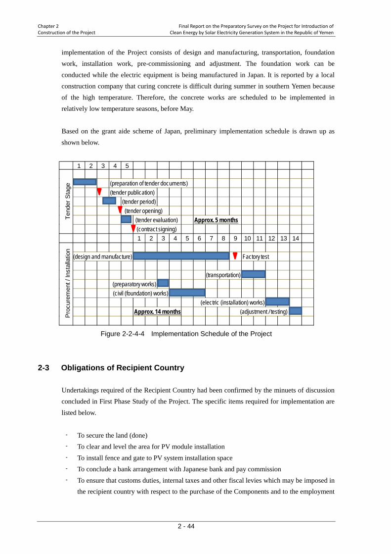
Chapter 2 Final Report on the Preparatory Survey on the Project for Introduction of Construction of the Project Clean Energy by Solar Electricity Generation System in the Republic of Yemen
2 - 44
implementation of the Project consists of design and manufacturing, transportation, foundation work, installation work, pre-commissioning and adjustment. The foundation work can be conducted while the electric equipment is being manufactured in Japan. It is reported by a local construction company that curing concrete is difficult during summer in southern Yemen because of the high temperature. Therefore, the concrete works are scheduled to be implemented in relatively low temperature seasons, before May. Based on the grant aide scheme of Japan, preliminary implementation schedule is drawn up as shown below.
Figure 2-2-4-4 Implementation Schedule of the Project
2-3 Obligations of Recipient Country Undertakings required of the Recipient Country had been confirmed by the minuets of discussion concluded in First Phase Study of the Project. The specific items required for implementation are listed below.
- To secure the land (done) - To clear and level the area for PV module installation - To install fence and gate to PV system installation space - To conclude a bank arrangement with Japanese bank and pay commission - To ensure that customs duties, internal taxes and other fiscal levies which may be imposed in
the recipient country with respect to the purchase of the Components and to the employment
1 2 3 4 5
(preparation of tender documents)(tender publication)
(tender period) (tender opening)
(tender evaluation) Approx. 5 months (contract signing)1 2 3 4 5 6 7 8 9 10 11 12 13 14
(design and manufacture) Factory test
(transportation)(preparatory works)(civil (foundation) works)
(electric (installation) works)Approx. 14 months (adjustment / testing)
Tend
er S
tage
Pro
cure
men
t / In
stal
latio
n
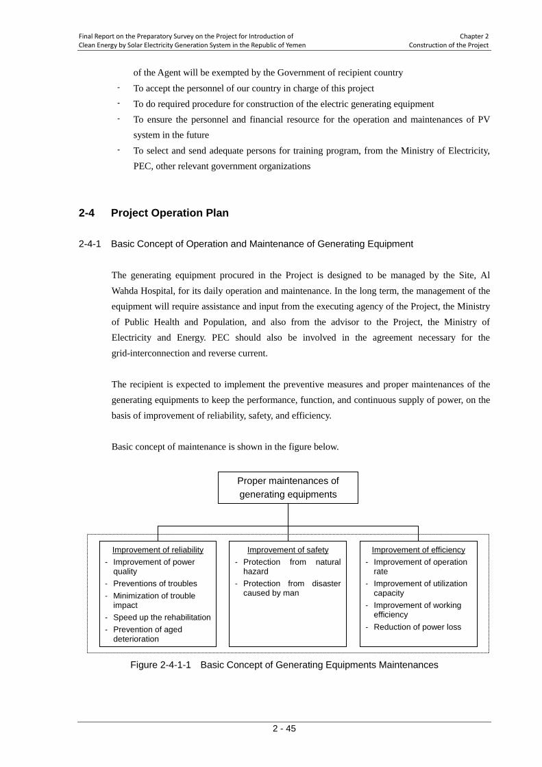
Final Report on the Preparatory Survey on the Project for Introduction of Chapter 2 Clean Energy by Solar Electricity Generation System in the Republic of Yemen Construction of the Project
2 - 45
of the Agent will be exempted by the Government of recipient country - To accept the personnel of our country in charge of this project - To do required procedure for construction of the electric generating equipment - To ensure the personnel and financial resource for the operation and maintenances of PV
system in the future - To select and send adequate persons for training program, from the Ministry of Electricity,
PEC, other relevant government organizations
2-4 Project Operation Plan 2-4-1 Basic Concept of Operation and Maintenance of Generating Equipment
The generating equipment procured in the Project is designed to be managed by the Site, Al Wahda Hospital, for its daily operation and maintenance. In the long term, the management of the equipment will require assistance and input from the executing agency of the Project, the Ministry of Public Health and Population, and also from the advisor to the Project, the Ministry of Electricity and Energy. PEC should also be involved in the agreement necessary for the grid-interconnection and reverse current. The recipient is expected to implement the preventive measures and proper maintenances of the generating equipments to keep the performance, function, and continuous supply of power, on the basis of improvement of reliability, safety, and efficiency. Basic concept of maintenance is shown in the figure below.
Figure 2-4-1-1 Basic Concept of Generating Equipments Maintenances
Proper maintenances of generating equipments
Improvement of reliability - Improvement of power
quality - Preventions of troubles - Minimization of trouble
impact - Speed up the rehabilitation - Prevention of aged
deterioration
Improvement of safety - Protection from natural
hazard - Protection from disaster
caused by man
Improvement of efficiency - Improvement of operation
rate - Improvement of utilization
capacity - Improvement of working
efficiency - Reduction of power loss
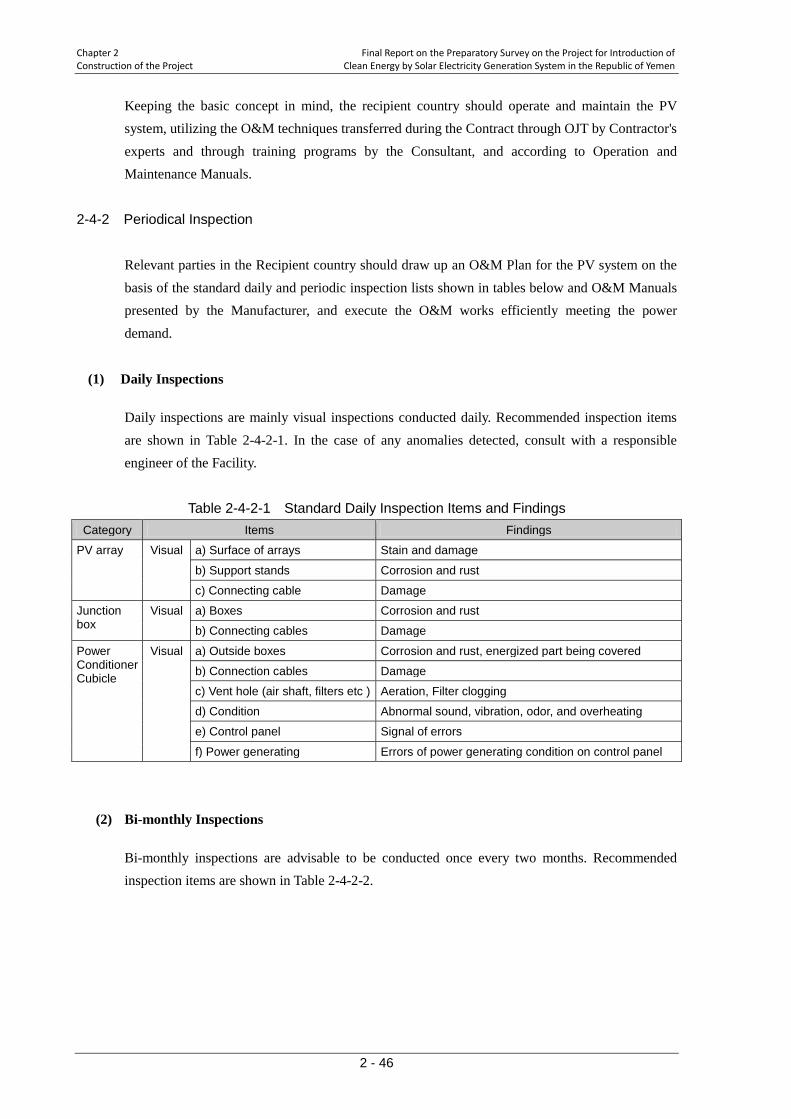
Chapter 2 Final Report on the Preparatory Survey on the Project for Introduction of Construction of the Project Clean Energy by Solar Electricity Generation System in the Republic of Yemen
2 - 46
Keeping the basic concept in mind, the recipient country should operate and maintain the PV system, utilizing the O&M techniques transferred during the Contract through OJT by Contractor's experts and through training programs by the Consultant, and according to Operation and Maintenance Manuals.
2-4-2 Periodical Inspection
Relevant parties in the Recipient country should draw up an O&M Plan for the PV system on the basis of the standard daily and periodic inspection lists shown in tables below and O&M Manuals presented by the Manufacturer, and execute the O&M works efficiently meeting the power demand.
(1) Daily Inspections
Daily inspections are mainly visual inspections conducted daily. Recommended inspection items are shown in Table 2-4-2-1. In the case of any anomalies detected, consult with a responsible engineer of the Facility.
Table 2-4-2-1 Standard Daily Inspection Items and Findings
Category Items Findings
PV array Visual a) Surface of arrays Stain and damage
b) Support stands Corrosion and rust
c) Connecting cable Damage
Junction box
Visual a) Boxes Corrosion and rust
b) Connecting cables Damage
Power Conditioner Cubicle
Visual a) Outside boxes Corrosion and rust, energized part being covered
b) Connection cables Damage
c) Vent hole (air shaft, filters etc ) Aeration, Filter clogging
d) Condition Abnormal sound, vibration, odor, and overheating
e) Control panel Signal of errors
f) Power generating Errors of power generating condition on control panel
(2) Bi-monthly Inspections
Bi-monthly inspections are advisable to be conducted once every two months. Recommended inspection items are shown in Table 2-4-2-2.

Final Report on the Preparatory Survey on the Project for Introduction of Chapter 2 Clean Energy by Solar Electricity Generation System in the Republic of Yemen Construction of the Project
2 - 47
Table 2-4-2-2 Standard Bi-monthly Inspection Items and Findings Category Items Findings
PV Sub-array4 Visual and touch
Earthing wires and grounding terminals
Junction with Earthing wires Loose screws
Junction box Visual and touch
a) Boxes Corrosion and damage
b) Connecting cables and terminals
Anomaly in wiring Loose screws
c) Earthing wires and connecting terminals
Anomaly in wiring Loose screws
Measurement and test
a) Insulating resistance <PV – Earthing wires> 0.2MΩ 5
<Output Terminals – Earthing wires>
or over, measured voltage DC500V ( Measure all circuits)
1MΩ or over Measured voltage DC500V
b) Open circuit voltage Specified voltage, Polarity (Measure all circuits)
Power conditioner Cubicle
Visual and touch
a) Outside boxes Corrosion and damage
b) Connecting cables and terminals
Anomaly in wiring Loose screws
c) Earthling wires and connecting terminals
Anomaly in wiring Loose screws
d) Vent hole (air shaft, filters etc.)
Aeration, Filter clogging
e) Condition Abnormal sound, vibration, odor, and overheating
f) Control panel Signal of errors
Measurement and test
a) Insulating resistance (Power conditioner - Earthing)
1MΩ or over Measured voltage DC500V
b) Control panel Operation checks (Display and power generating)
c) Re-starting Timer Confirmation of automatic start-up
Switch for PV Visual and touch
a) Connecting terminals of switch
Loose screws
Test a) Insulating resistance 1MΩor over Measured voltage DC500V
2-4-3 Long term Operation and Maintenance
Although the expected operation life of PV modules and power conditioners, the main components of PV system, varies by manufacturers, generally PV modules6 are considered to work for 20 years and power conditioners7
4 PV modules should be checked for the following points
are considered to work for 15 years under the proper
- Smudges on the surface, cracks and discolorations on the surface, etc, - Deformation of support structure, rust, loosened bolts, etc.
5 Allowable Insulating resistance 0.4MΩ or over for Insulating resistance of 300V or over.
6 "Photovoltaic Power Generation System, 3rd edition", September 2006, Japan Photovoltaic Energy Association. 7 Based on the interviews to manufacturers.
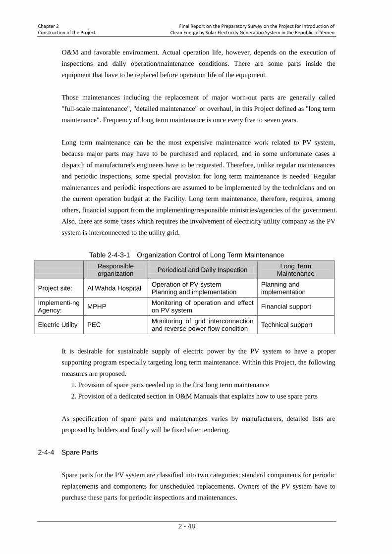
Chapter 2 Final Report on the Preparatory Survey on the Project for Introduction of Construction of the Project Clean Energy by Solar Electricity Generation System in the Republic of Yemen
2 - 48
O&M and favorable environment. Actual operation life, however, depends on the execution of inspections and daily operation/maintenance conditions. There are some parts inside the equipment that have to be replaced before operation life of the equipment. Those maintenances including the replacement of major worn-out parts are generally called "full-scale maintenance", "detailed maintenance" or overhaul, in this Project defined as "long term maintenance". Frequency of long term maintenance is once every five to seven years. Long term maintenance can be the most expensive maintenance work related to PV system, because major parts may have to be purchased and replaced, and in some unfortunate cases a dispatch of manufacturer's engineers have to be requested. Therefore, unlike regular maintenances and periodic inspections, some special provision for long term maintenance is needed. Regular maintenances and periodic inspections are assumed to be implemented by the technicians and on the current operation budget at the Facility. Long term maintenance, therefore, requires, among others, financial support from the implementing/responsible ministries/agencies of the government. Also, there are some cases which requires the involvement of electricity utility company as the PV system is interconnected to the utility grid.
Table 2-4-3-1 Organization Control of Long Term Maintenance
Responsible organization Periodical and Daily Inspection Long Term
Maintenance
Project site: Al Wahda Hospital Operation of PV system Planning and implementation
Planning and implementation
Implementi-ng Agency: MPHP Monitoring of operation and effect
on PV system Financial support
Electric Utility PEC Monitoring of grid interconnection and reverse power flow condition Technical support
It is desirable for sustainable supply of electric power by the PV system to have a proper supporting program especially targeting long term maintenance. Within this Project, the following measures are proposed.
1. Provision of spare parts needed up to the first long term maintenance 2. Provision of a dedicated section in O&M Manuals that explains how to use spare parts
As specification of spare parts and maintenances varies by manufacturers, detailed lists are proposed by bidders and finally will be fixed after tendering.
2-4-4 Spare Parts
Spare parts for the PV system are classified into two categories; standard components for periodic replacements and components for unscheduled replacements. Owners of the PV system have to purchase these parts for periodic inspections and maintenances.
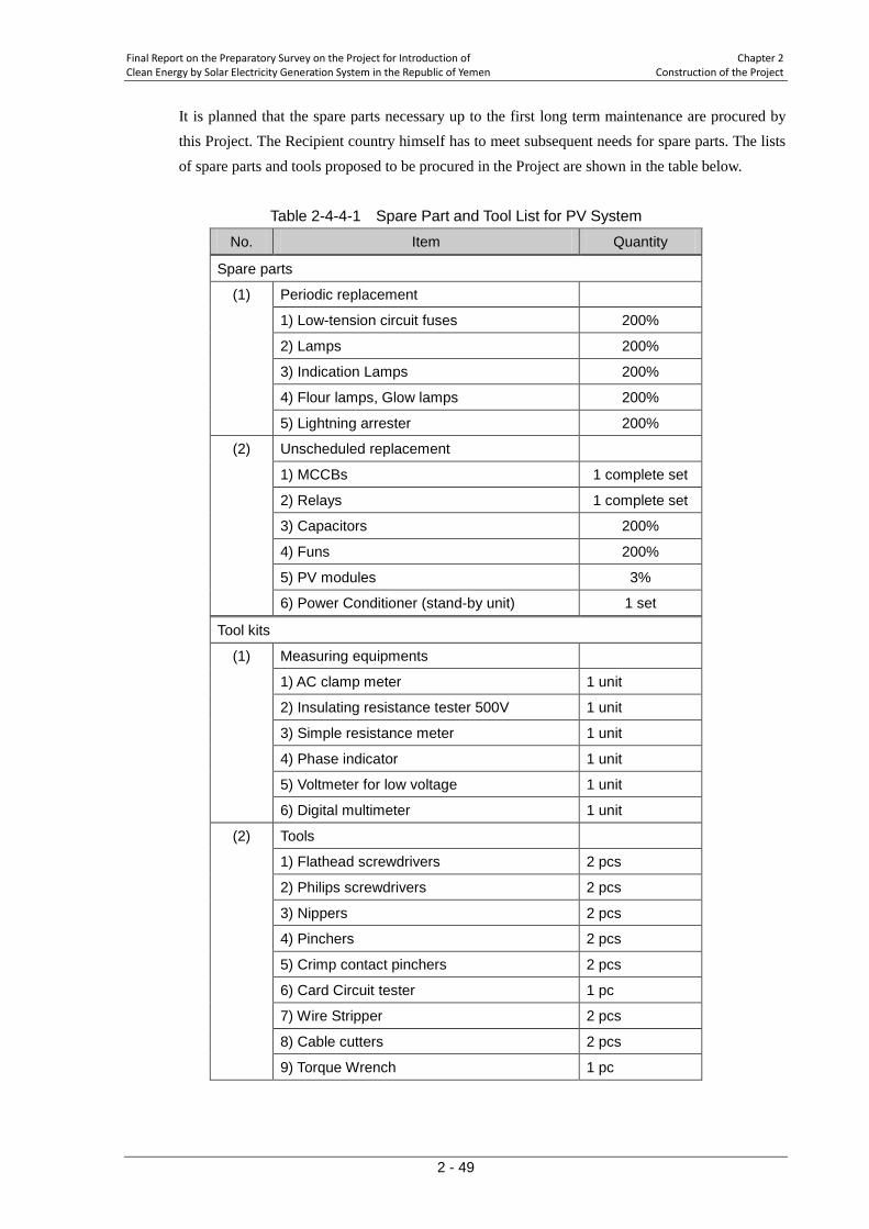
Final Report on the Preparatory Survey on the Project for Introduction of Chapter 2 Clean Energy by Solar Electricity Generation System in the Republic of Yemen Construction of the Project
2 - 49
It is planned that the spare parts necessary up to the first long term maintenance are procured by this Project. The Recipient country himself has to meet subsequent needs for spare parts. The lists of spare parts and tools proposed to be procured in the Project are shown in the table below.
Table 2-4-4-1 Spare Part and Tool List for PV System
No. Item Quantity
Spare parts
(1) Periodic replacement
1) Low-tension circuit fuses 200%
2) Lamps 200%
3) Indication Lamps 200%
4) Flour lamps, Glow lamps 200%
5) Lightning arrester 200%
(2) Unscheduled replacement
1) MCCBs 1 complete set
2) Relays 1 complete set
3) Capacitors 200%
4) Funs 200%
5) PV modules 3%
6) Power Conditioner (stand-by unit) 1 set
Tool kits
(1) Measuring equipments
1) AC clamp meter 1 unit
2) Insulating resistance tester 500V 1 unit
3) Simple resistance meter 1 unit
4) Phase indicator 1 unit
5) Voltmeter for low voltage 1 unit
6) Digital multimeter 1 unit
(2) Tools
1) Flathead screwdrivers 2 pcs
2) Philips screwdrivers 2 pcs
3) Nippers 2 pcs
4) Pinchers 2 pcs
5) Crimp contact pinchers 2 pcs
6) Card Circuit tester 1 pc
7) Wire Stripper 2 pcs
8) Cable cutters 2 pcs
9) Torque Wrench 1 pc
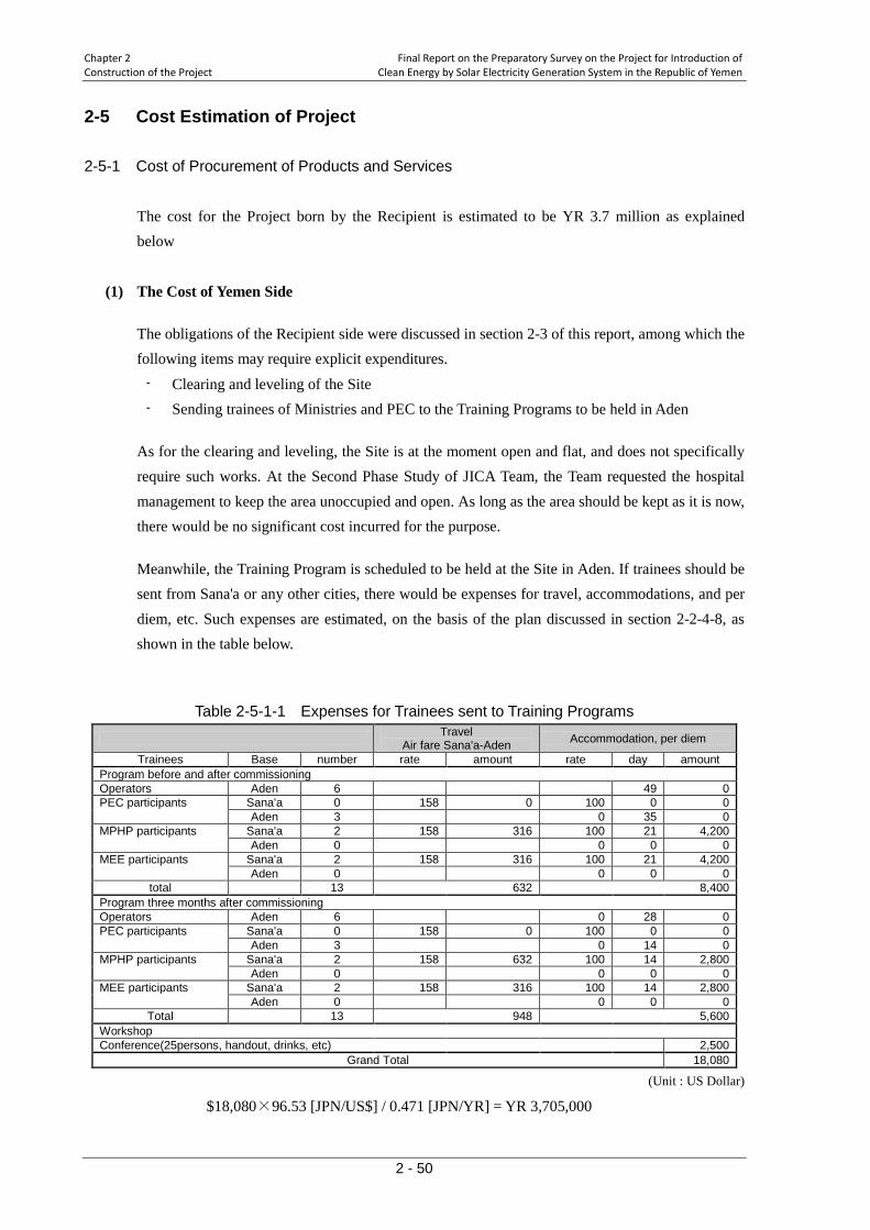
Chapter 2 Final Report on the Preparatory Survey on the Project for Introduction of Construction of the Project Clean Energy by Solar Electricity Generation System in the Republic of Yemen
2 - 50
2-5 Cost Estimation of Project 2-5-1 Cost of Procurement of Products and Services
The cost for the Project born by the Recipient is estimated to be YR 3.7 million as explained below
(1) The Cost of Yemen Side
The obligations of the Recipient side were discussed in section 2-3 of this report, among which the following items may require explicit expenditures.
- Clearing and leveling of the Site - Sending trainees of Ministries and PEC to the Training Programs to be held in Aden
As for the clearing and leveling, the Site is at the moment open and flat, and does not specifically require such works. At the Second Phase Study of JICA Team, the Team requested the hospital management to keep the area unoccupied and open. As long as the area should be kept as it is now, there would be no significant cost incurred for the purpose.
Meanwhile, the Training Program is scheduled to be held at the Site in Aden. If trainees should be sent from Sana'a or any other cities, there would be expenses for travel, accommodations, and per diem, etc. Such expenses are estimated, on the basis of the plan discussed in section 2-2-4-8, as shown in the table below.
Table 2-5-1-1 Expenses for Trainees sent to Training Programs
Travel Air fare Sana'a-Aden Accommodation, per diem
Trainees Base number rate amount rate day amount Program before and after commissioning Operators Aden 6 49 0 PEC participants Sana'a 0 158 0 100 0 0 Aden 3 0 35 0 MPHP participants Sana'a 2 158 316 100 21 4,200 Aden 0 0 0 0 MEE participants Sana'a 2 158 316 100 21 4,200 Aden 0 0 0 0
total 13 632 8,400 Program three months after commissioning Operators Aden 6 0 28 0 PEC participants Sana'a 0 158 0 100 0 0 Aden 3 0 14 0 MPHP participants Sana'a 2 158 632 100 14 2,800 Aden 0 0 0 0 MEE participants Sana'a 2 158 316 100 14 2,800 Aden 0 0 0 0
Total 13 948 5,600 Workshop Conference(25persons, handout, drinks, etc) 2,500
Grand Total 18,080
(Unit : US Dollar)
$18,080×96.53 [JPN/US$] / 0.471 [JPN/YR] = YR 3,705,000
Final Report on the Preparatory Survey on the Project for Introduction of Chapter 2 Clean Energy by Solar Electricity Generation System in the Republic of Yemen Construction of the Project
2 - 51
(2) Condition of Calculation
1. Time of calculation October, 2009 2. Exchange rates of foreign currencies US$ 1 = JPN 96.53
YR(Yemen Rial) 1 = JPN 0.471 3. Time of the Event as shown in Figure 2-2-4-4 4. Remarks Calculation is done according to the rules for Japan's
Grand Aid Programmes 2-5-2 Cost of Operation and Maintenance
(1) Estimation of Cost of Operation and Maintenance
The following cost factors are considered here. 1. Cost for daily operation 2. Cost for personnel in operation and maintenance 3. Cost for spare parts to be required 4. Cost for renovation
Cost estimation in this section does not consider unlikely, but still possible, breakdown of equipment and resulting repair cost. Also, repair cost after vandalism or sabotage is not considered. Further, the cost of requesting Japanese manufacturer's engineers to be present at the Site for repair and/or diagnosis works is not considered.
1) Cost for Daily Operation
As a PV system does not consume any fuels, there would be very few expenses under this category. To be very precise, there are expenses for water used in cleaning of PV modules, electricity for system monitoring and air conditioning during not-generating hours of the day, which are small enough to be negligible.
2) Cost for Personnel in Operation and Maintenance
The PV system to be procured in the Project can be, and will be operated and maintained by the existing maintenance staff of the facility. Therefore, operating and maintaining the PV system does not require additional persons to be employed by the facility.
Meanwhile, part of working hours of the maintenance staff will be taken up by operation and maintenance activities, it is converted to monetary terms for reference purpose. (Daily cost of a person is assumed to be $22.86.)
- Daily inspection (modules and cubicle) 0.5 hours per day 0.5hr/8hr [daily working hrs] times $22.86 = $1.37 per day
- Cleaning of modules (1hr per month per kW of modules) 30hours per month
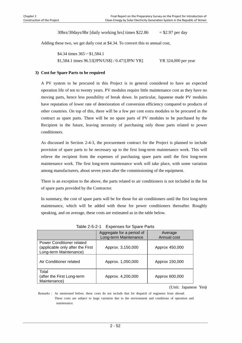
Chapter 2 Final Report on the Preparatory Survey on the Project for Introduction of Construction of the Project Clean Energy by Solar Electricity Generation System in the Republic of Yemen
2 - 52
30hrs/30days/8hr [daily working hrs] times $22.86 = $2.97 per day
Adding these two, we get daily cost at $4.34. To convert this to annual cost,
$4.34 times 365=$1,584.1 $1,584.1 times 96.53[JPN/US$] / 0.471[JPN/ YR] YR 324,000 per year
3) Cost for Spare Parts to be required
A PV system to be procured in this Project is in general considered to have an expected operation life of ten to twenty years. PV modules require little maintenance cost as they have no moving parts, hence less possibility of break down. In particular, Japanese made PV modules have reputation of lower rate of deterioration of conversion efficiency compared to products of other countries. On top of this, there will be a few per cent extra modules to be procured in the contract as spare parts. There will be no spare parts of PV modules to be purchased by the Recipient in the future, leaving necessity of purchasing only those parts related to power conditioners.
As discussed in Section 2-4-3, the procurement contract for the Project is planned to include provision of spare parts to be necessary up to the first long-term maintenance work. This will relieve the recipient from the expenses of purchasing spare parts until the first long-term maintenance work. The first long-term maintenance work will take place, with some variation among manufacturers, about seven years after the commissioning of the equipment.
There is an exception to the above, the parts related to air conditioners is not included in the list of spare parts provided by the Contractor.
In summary, the cost of spare parts will be for those for air conditioners until the first long-term maintenance, which will be added with those for power conditioners thereafter. Roughly speaking, and on average, these costs are estimated as in the table below.
Table 2-5-2-1 Expenses for Spare Parts
Aggregate for a period of Long-term Maintenance
Average Annual cost
Power Conditioner related (applicable only after the First Long-term Maintenance)
Approx. 3,150,000 Approx 450,000
Air Conditioner related Approx. 1,050,000 Approx 150,000
Total (after the First Long-term Maintenance)
Approx. 4,200,000 Approx 600,000
(Unit: Japanese Yen) Remarks : As mentioned before, these costs do not include that for dispatch of engineers from abroad.
These costs are subject to large variation due to the environment and conditions of operation and maintenance.
Final Report on the Preparatory Survey on the Project for Introduction of Chapter 2 Clean Energy by Solar Electricity Generation System in the Republic of Yemen Construction of the Project
2 - 53
Converting these figures into Yemen Rials, we have the expected purchase cost of spare parts as below.
Before the First Long-term Maintenance JPN150,000/0.471[JNP/ YR] = YR 318,000 per year
After the First Long-term Maintenance JPN 600,000/0.471[JNP/ YR] =YR 1,373,000 per year
4) Cost for renovation
As mentioned in the previous section, PV modules have long expected life with slow deterioration rate. Therefore, PV modules do not require replacement during the lifetime of the whole PV system.
The power conditioners on the other hand are just like ordinary equipment in the power utility industry and some of their parts have statutory service lives. Those parts that have been deteriorated should be, on occasions of periodical and/or long-term maintenance, replaced with the spare parts considered in the previous section. Beyond this, overall replacement of the equipment or renovation is considered out of scope of this Project.
(2) Financial Resources for operation and Maintenance
A financial benefit of having PV equipment accrues to a party who pays electricity bills. As Al Wahda Hospital is not paying electricity bills, the hospital will not be financially benefited from the Project. Further, considering the limited budget of the hospital it would be too much a burden for the hospital to bear the cost of maintenance discussed in the previous section.
Here, it makes more sense to assume that the governments who are paying the bill are also liable to pay the cost of operation and maintenance of the PV system.
The financial value of the electricity generated by the PV system will be, although difficult to estimate accurately as there may be some energy produced but wasted due to the balance of supply and demand (no reverse flow), calculated on the basis of the expected annual production of energy 500MWh. Assuming this energy is all consumed in the Hospital and contributes to the reduction of electricity bills, using current electricity tariff of the Hospital, YR 30 per kWh, we obtain the financial value of the power as below.
500MWh ×YR30/kWh=YR 15,000,000
As this value is much larger than the aforementioned operation and maintenance cost, the Project will prove to put no additional financial burden to the Recipient
Chapter 2 Final Report on the Preparatory Survey on the Project for Introduction of Construction of the Project Clean Energy by Solar Electricity Generation System in the Republic of Yemen
2 - 54
2-6 Other Relevant Issues
(1) Handling of Reverse Current
In this study, the PV system is designed in a way that reverse current to the utility grid is not permitted even when there is surplus power generated, due to the decision of the public electricity company, PEC. Al Wahda Hospital is presently under the large scale rehabilitation works and when the works are complete, the consumption of electricity at the hospital is expected to be much larger than the level measured at the Site in this study. The surplus power will not be produced that much for the design capacity of the PV system. However, considering the possibility that the country may have similar kind of projects in the future, this Project may have provided a timely opportunity the related authorities to consider rules and regulations for the handling of reverse current. The design of the PV system to be provided in the Project has added to an ordinary, with-reverse current system a control to suppress the occurrence of reverse flow. And this control can be cancelled by the operation on the control panel of the System (when there is a surplus power).
In the training programs (soft component) to which officials of the Ministry of Electricity and PEC are encouraged to participate, the reverse current issue should be taken up to prepare them for the similar projects in the future and to prompt these officials to engage in the discussion on the issue.
(2) Operation and Maintenance Organization
For this Project, the Ministry of Public Health and Population will be the executing agency, and Al Wahda Hospital will be taking care of daily operation and maintenance. Staff of maintenance department of the Hospital has been in charge of managing electric facilities of the Hospital including a diesel generator unit, and they are well capable of handling the PV system, provided that they have been given knowledge and training for the new equipment. In particular, as the long-term maintenance works demand technically higher level of knowledge, PEC who are very much experienced in electric equipment and its supervisor, the Ministry of Electricity, are expected to provide support.
(3) Use of Stand-alone Function
This Project is designed, on the basis of the request from the Hospital, to furnish the PV system with the stand-alone function. In order to utilize this function safely and effectively, the mechanism of photovoltaics and the working of PV equipment, characteristics of electric instruments on the demand side (destination of stand-alone power) and their arrangement, must be fully understood and managed.
Therefore, it is not only those technicians who will be directly in charge of operation and

Final Report on the Preparatory Survey on the Project for Introduction of Chapter 2 Clean Energy by Solar Electricity Generation System in the Republic of Yemen Construction of the Project
2 - 55
maintainance of the PV system, but also engineers and researchers who are using electric equipment in the Hospital, that have to acquire accurate and sufficient understanding of the stand-alone function, through an attendance to the training program or any other means.
CHAPTER 3
PROJECT EVALUATION AND RECOMMENDATIONS
Final Report on the Preparatory Survey on the Project for Introduction of Chapter 3 Clean Energy by Solar Electricity Generation System in the Republic of Yemen Project Eavluation and Recommendatinos
3 - 1
Chapter 3 Project Evaluation and Recommendations
3-1 Recommendations 3-1-1 Prerequisite to Project Implementation
There are prerequisites for the Project to be implemented without impediments, which are shown below.
(1) Handling of Reverse Current
Although the reverse current is not permitted in this Project, in the training programs (soft component) to which officials of the Ministry of Electricity and PEC are encouraged to participate, the reverse current issue should be taken up to prepare them for the similar projects in the future and to prompt these officials to engage in the discussion on the issue.
(2) Operation and Maintenance Organization
For this Project, the Ministry of Public Health and Population will be the executing agency, and Al Wahda Hospital will be taking care of daily operation and maintenance. Staff of maintenance department of the Hospital will be well capable of handling the PV system, provided that they have been given knowledge and training for the new equipment. In particular, as the long-term maintenance works demand technically higher level of knowledge, PEC and its supervisor, the Ministry of Electricity, are expected to provide support.
(3) Use of Stand-alone Function
This Project is designed, on the basis of the request from the Hospital, to furnish the PV system with the stand-alone function. In order to utilize this function safely and effectively, the mechanism of photovoltaics and the working of PV equipment, characteristics of electric instruments on the demand side (destination of stand-alone power) and their arrangement, must be fully understood and managed.
3-1-2 External Conditions to Achievement of Project Objectives
Yemen side should work on the following things for the Project's to take effects sustainably.
(1) Expectations on the Ministry of Electricity
In this Project, the implementation agency is the Ministry of Public Health and Population, and the

Chapter 3 Final Report on the Preparatory Survey on the Project for Introduction of Project Eavluation and Recommendatinos Clean Energy by Solar Electricity Generation System in the Republic of Yemen
3 - 2
Ministry of Energy is given a position of an advisor. The reason behind this arrangement may have been that the grid-interconnected PV system provided by the Project did not appear directly to meet the energy policy of the country in which the use of solar energy is to be advanced in the field of rural electrification.
The Ministry of Electricity has separated the rural electrification business using solar energy from the public electricity company, and is seeking to promote private investment in the field, with the supervision by the newly established rural electrification agency. There seems to be not much information available concerning renewable energy resources which is needed by private investors in their decision making and managing the risks involved. Having the records of power production and that of long-term operation and maintenance in this Project publicized can provide information very useful in planning the solar projects with certain size. This kind of utilization of technical knowledge obtained with the Project is not the work expected for the Ministry of Public Health and Population, but for the Ministry of Electricity.
(2) Technical Assistance, Cooperation with Other Donors
As mentioned above, the Ministry of Energy is promoting the use of solar energy in the field of rural electrification, seeking private investment in mini-grid in remote areas. Meanwhile GTZ of Germany has withdrawn from the energy sector, very likely leaving the solar uses to individual independent solar systems for schools and medical facilities in rural areas away from the national power network.
Considering the technical advantages of Japan, what Yemen would demand Japan to provide in the form of technical assistance are;
1) to prepare necessary institutions and markets to promote private investment in rural electrification,
2) to improve planning, installing, operating and maintaining single/grid-interconnected solar facilities,
3) to use and interconnect other renewable resources together with solar generation.
Among them, 1) has been already established in the policy documents with an assistance from GTZ. Therefore, Japanese assistance is desired in 2) and 3) above.
Yemeni Government should take a lead, with cooperation from Japanese side, to realize assistance projects mentioned above.
Final Report on the Preparatory Survey on the Project for Introduction of Chapter 3 Clean Energy by Solar Electricity Generation System in the Republic of Yemen Project Eavluation and Recommendatinos
3 - 3
3-2 Project Evaluation 3-2-1 Validity of the Project
The Project is considered valid on the basis of following points.
(1) Reduction of Fossil Fuel Consumption and Carbon Dioxide Emission
Yemen depends completely on fossil fuel for the primary energy for electric generation. Therefore, energy generated by the PV system of this Project will all contribute to the reduction of consumption of fossil fuel, hence the emission of CO2. This Project is considered appropriate as it will deliver the direct effect as follows,
Reduction of fossil fuel consumption Reduction of carbon dioxide emission Reduction of the Country's dependence on imported fossil fuel
(2) Consistency with Higher Policy
The energy policy and climate change mitigation measures of Yemen, while the government is aware of the abundant endowment of solar potential in the country, focuses on its use in independent, isolated use (e.g. SHS) in rural areas. Villages with a certain scale are, if away from the national power grid, planned to be electrified by mini-grid using solar power, realized by private investments. On the other hand the policy has been seeking to harness solar thermal and wind energy for the renewable energy to be connected to the national grid. This Project, to have PV system interconnected to the national grid, is something that the policy has not been aware of.
Aden City, where the chosen Site situates, has an advantage in terms of climate conditions for the utilization of solar power. If this Project can demonstrate the effectiveness of PV use in Yemen, it will have a good impact on the energy policy of Yemen. At the same time it will have a good impact on the promotion of private investment in PV uses.
It should be also pointed out that Al Wahda Hospital is situated in the southern part of Yemen. The Yemeni government is committed to balanced development of northern and southern parts of the Country. This Project will be welcomed in that it helps balance the flow of development assistance to parts of Yemen
In this manner, the Project is compatible with the energy policy of Yemen and considered appropriate.
(3) Operation and Maintenance Capacity at the Site
Facility maintenance staff of Al Wahda Hospital, although does not seem to have education in
Chapter 3 Final Report on the Preparatory Survey on the Project for Introduction of Project Eavluation and Recommendatinos Clean Energy by Solar Electricity Generation System in the Republic of Yemen
3 - 4
advanced electric engineering, has been managing the electrical facilities of the Hospital which are getting older, and securing power even for the most advanced medical equipment, on the basis of their experience. Therefore, they are considered well capable of operating and maintaining the PV system to be installed, once they have been given necessary knowledge and adequate management tools.
The Site chosen for the Project is considered appropriate for the reasons given above.
(4) Financial Weight of Operation and Maintenance
The energy expected to be produced by the PV system of the Project can be valued on the basis of electricity tariff charged to the Hospital to be approximately YR 15 million, which is much larger than the long-term cost of operation and maintenance. Therefore, the Project will not put a burden on, but contribute to, the finance of the Country.
(6) Socio-Environmental Considerations
The photovoltaic generation system to be installed by the Program will work to reduce the consumption of fossil fuel, leading to reduction of emission from thermal power plants locally, and that of CO2 emission globally.
Meanwhile, it is pointed out that the Contractor should plan the installation works carefully so that there would be no significant impact on environment or accidents during the works.
(7) Benefit from Advanced Technology of Japanese Products
PV equipment consists mostly of PV modules, power conditioners and their peripherals. Especially, PV modules and power conditioners made by Japanese manufacturers have technical advantages over other countries in their efficiency, longevity, reliability, etc. in the market. As this Project is limiting the country of origin of this equipment to Japan, the Project will be able to offer advanced technology of Japanese products.
3-2-2 Effectiveness of the Project
(1) Overall Effect
By the introduction of the photovoltaic generation system, the Recipient country can reduce the consumption of fuel oil and diesel oil, or do without additional consumption of such fossil fuel, resulting in the reduction of CO2 emissions. This will contribute to the climate change mitigation policy of the Recipient country. On top of this, to install a photovoltaic generation system of the largest scale in the second largest city of the Recipient country, we could expect demonstration and educational effects of clean energy use including solar power on the wider public within the
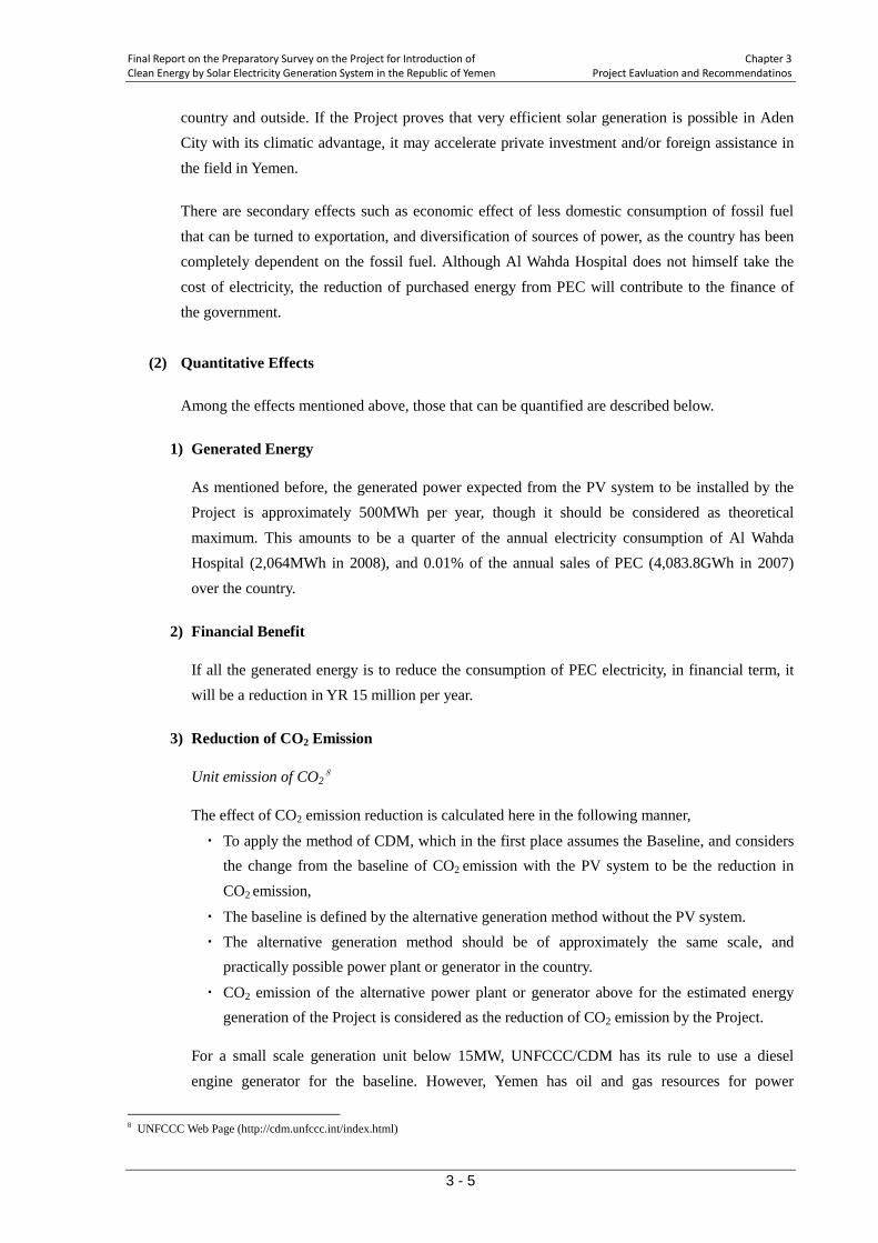
Final Report on the Preparatory Survey on the Project for Introduction of Chapter 3 Clean Energy by Solar Electricity Generation System in the Republic of Yemen Project Eavluation and Recommendatinos
3 - 5
country and outside. If the Project proves that very efficient solar generation is possible in Aden City with its climatic advantage, it may accelerate private investment and/or foreign assistance in the field in Yemen.
There are secondary effects such as economic effect of less domestic consumption of fossil fuel that can be turned to exportation, and diversification of sources of power, as the country has been completely dependent on the fossil fuel. Although Al Wahda Hospital does not himself take the cost of electricity, the reduction of purchased energy from PEC will contribute to the finance of the government.
(2) Quantitative Effects
Among the effects mentioned above, those that can be quantified are described below.
1) Generated Energy
As mentioned before, the generated power expected from the PV system to be installed by the Project is approximately 500MWh per year, though it should be considered as theoretical maximum. This amounts to be a quarter of the annual electricity consumption of Al Wahda Hospital (2,064MWh in 2008), and 0.01% of the annual sales of PEC (4,083.8GWh in 2007) over the country.
2) Financial Benefit
If all the generated energy is to reduce the consumption of PEC electricity, in financial term, it will be a reduction in YR 15 million per year.
3) Reduction of CO2 Emission
Unit emission of CO28
The effect of CO2 emission reduction is calculated here in the following manner,
・ To apply the method of CDM, which in the first place assumes the Baseline, and considers the change from the baseline of CO2 emission with the PV system to be the reduction in CO2 emission,
・ The baseline is defined by the alternative generation method without the PV system. ・ The alternative generation method should be of approximately the same scale, and
practically possible power plant or generator in the country.
・ CO2 emission of the alternative power plant or generator above for the estimated energy generation of the Project is considered as the reduction of CO2 emission by the Project.
For a small scale generation unit below 15MW, UNFCCC/CDM has its rule to use a diesel engine generator for the baseline. However, Yemen has oil and gas resources for power
8 UNFCCC Web Page (http://cdm.unfccc.int/index.html)
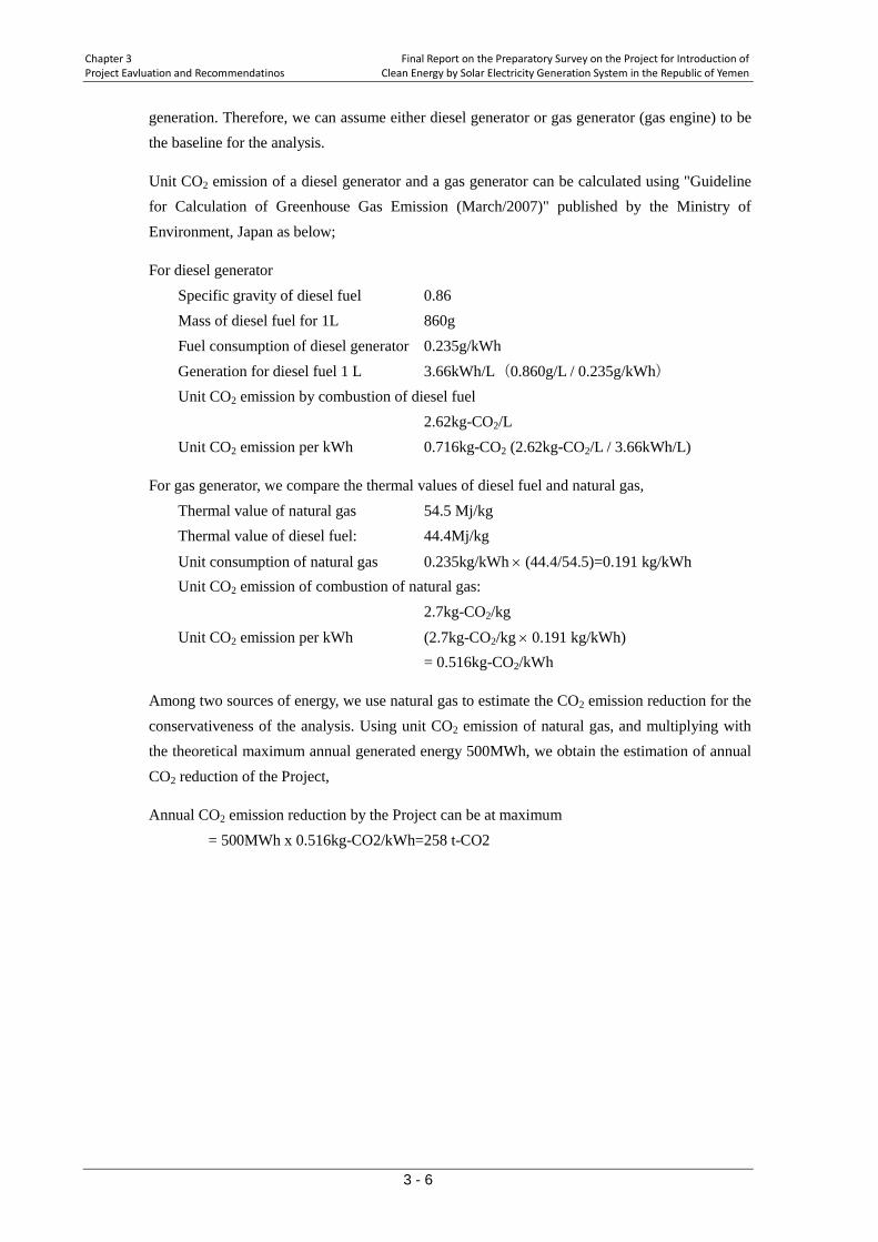
Chapter 3 Final Report on the Preparatory Survey on the Project for Introduction of Project Eavluation and Recommendatinos Clean Energy by Solar Electricity Generation System in the Republic of Yemen
3 - 6
generation. Therefore, we can assume either diesel generator or gas generator (gas engine) to be the baseline for the analysis.
Unit CO2 emission of a diesel generator and a gas generator can be calculated using "Guideline for Calculation of Greenhouse Gas Emission (March/2007)" published by the Ministry of Environment, Japan as below;
For diesel generator Specific gravity of diesel fuel 0.86 Mass of diesel fuel for 1L 860g Fuel consumption of diesel generator 0.235g/kWh Generation for diesel fuel 1 L 3.66kWh/L(0.860g/L / 0.235g/kWh) Unit CO2 emission by combustion of diesel fuel 2.62kg-CO2/L Unit CO2 emission per kWh 0.716kg-CO2 (2.62kg-CO2/L / 3.66kWh/L)
For gas generator, we compare the thermal values of diesel fuel and natural gas, Thermal value of natural gas 54.5 Mj/kg Thermal value of diesel fuel: 44.4Mj/kg
Unit consumption of natural gas 0.235kg/kWh × (44.4/54.5)=0.191 kg/kWh Unit CO2 emission of combustion of natural gas: 2.7kg-CO2/kg
Unit CO2 emission per kWh (2.7kg-CO2/kg × 0.191 kg/kWh) = 0.516kg-CO2/kWh
Among two sources of energy, we use natural gas to estimate the CO2 emission reduction for the conservativeness of the analysis. Using unit CO2 emission of natural gas, and multiplying with the theoretical maximum annual generated energy 500MWh, we obtain the estimation of annual CO2 reduction of the Project,
Annual CO2 emission reduction by the Project can be at maximum = 500MWh x 0.516kg-CO2/kWh=258 t-CO2

DRAWINGS

DRAWINGS
Number Title
NO. 01 SINGLE LINE DIAGRAM
NO. 02 SINGLE LINE DIAGRAM (PV SYSTEM)
NO. 03 GENERAL LAYOUT PLAN
NO. 04 BRANCH SWITCHERS FOR LOAD
NO. 05 CABLE LAYOUT PLAN
NO. 06 EQUIPMENTS LAYOUT (NO. 1 ELECTRIC ROOM)
NO. 07 EQUIPMENTS LAYOUT (BUILDING B ELECTRIC ROOM)
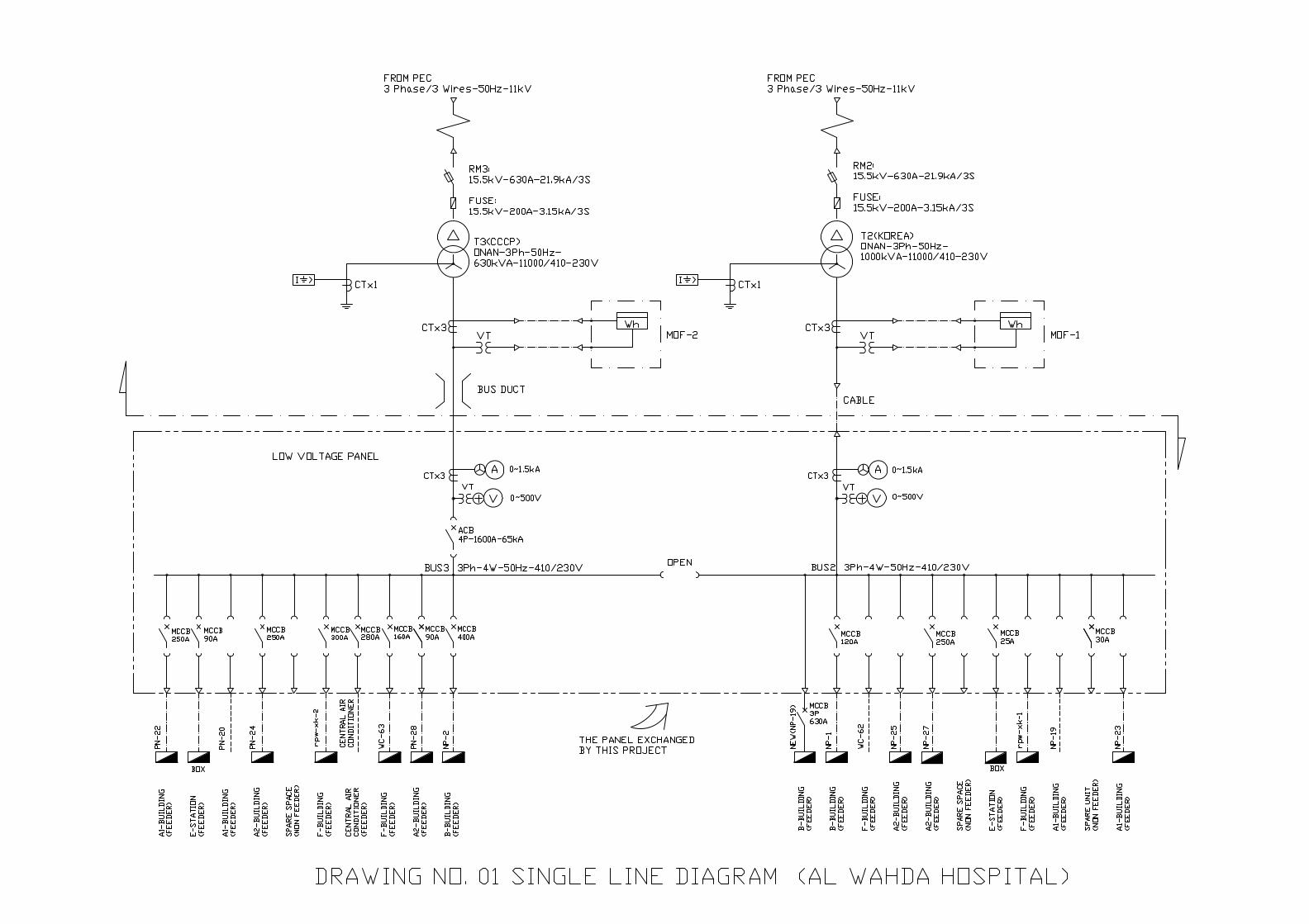
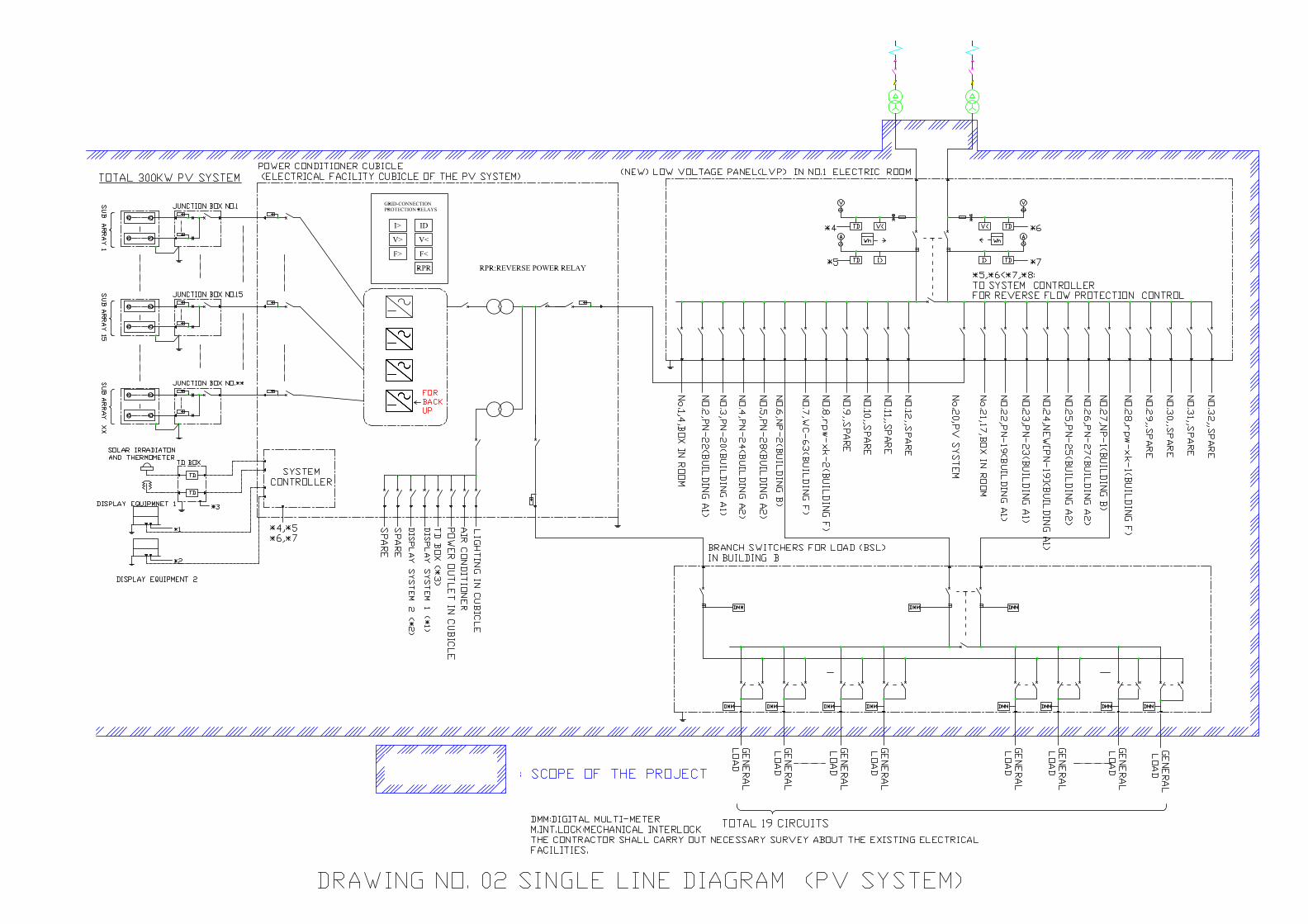
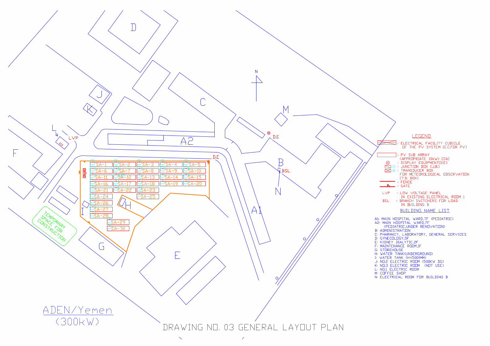
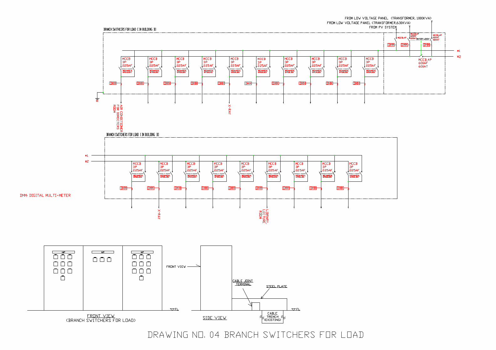
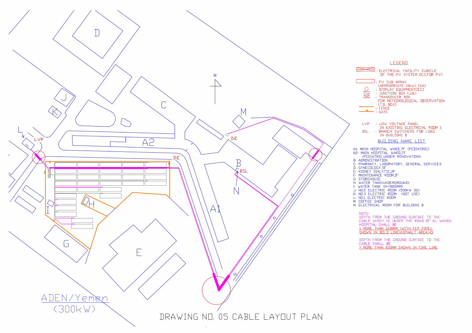
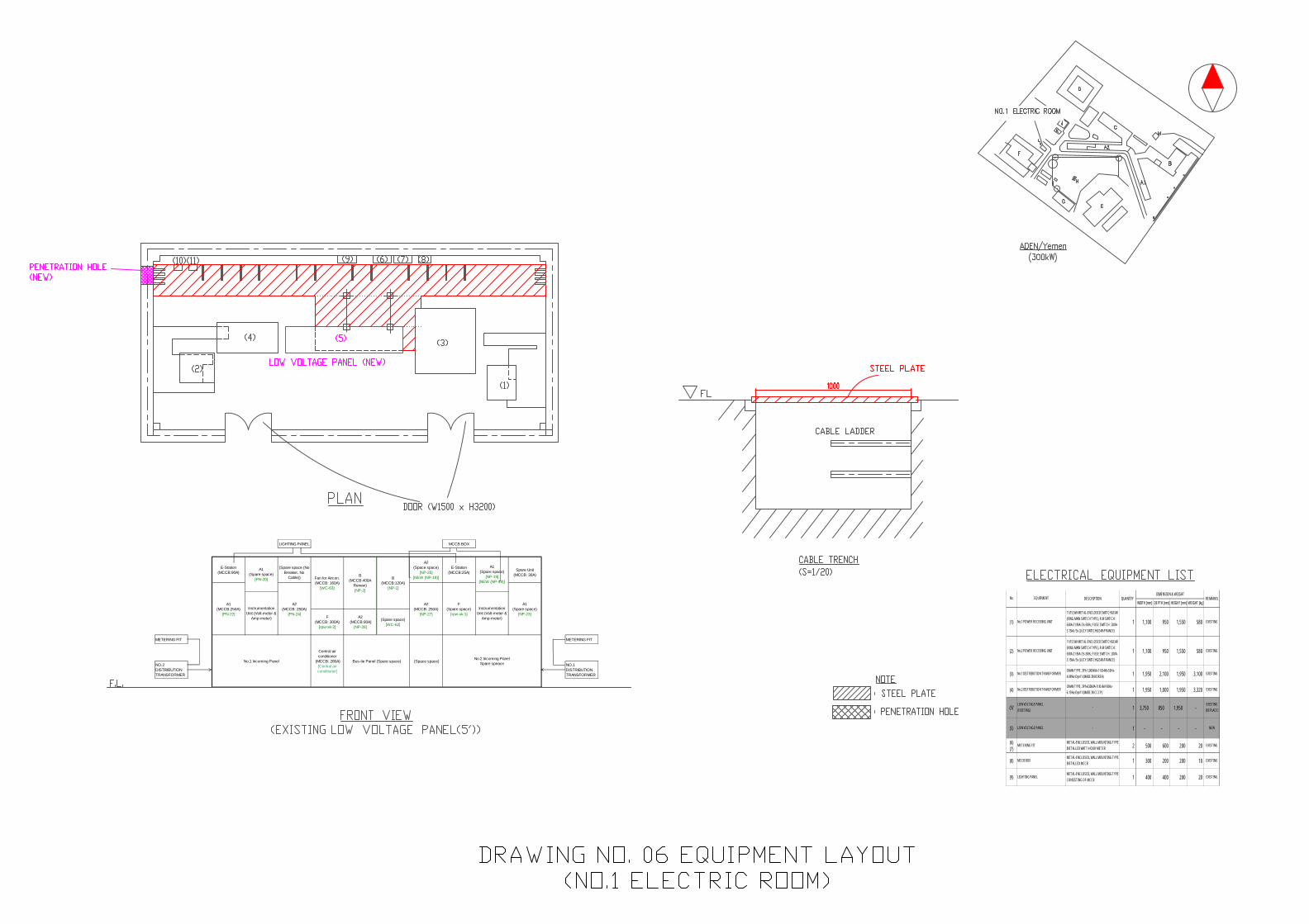
LIGHTING PANEL MCCB BOX
METERING FIT METERING FIT
NO.2DISTRIBUTIONTRANSFORMER
InstrumentationUnit (Volt-meter &
Amp-meter)F(MCCB: 300A)
[rpw-xk-2]
A2 (MCCB:90A)
[NP-28]
(Spare space)[WC-62]
No.1 Incoming Panel
Central airconditioner
(MCCB: 280A)[Central airconditioner]
Bus-tie Panel (Spare space)
F(Spare space)
[rpw-xk-1]
A1(Spare space)
[NP-23]Instrumentation
Unit (Volt-meter &Amp-meter)
(Space space)No.2 Incoming Panel
Spare speace
A2(Space space)
[NP-25][NEW (NP-19)]
E-Station(MCCB:25A)
A1(Spare space)
[NP-19][NEW (NP-19)]
Spare Unit
(MCCB: 30A)
NO.1DISTRIBUTIONTRANSFORMER
E-Station(MCCB:90A)
A1(Spare space)
[PN-20]
(Spare space (No
Breaker, NoCable)) Fan for Aircon.
(MCCB: 160A)[WC-63]
B(MCCB:400A
Renew)[NP-2]
B(MCCB:120A)
[NP-1]
A1(MCCB:250A)
[PN-22]
A2(MCCB: 250A)
[PN-24]
A2(MCCB: 250A)
[NP-27]
WIDTH [mm] DEPTH [mm] HEIGHT [mm] WEIGHT [kg]
(1) No.1 POWER RECEIVING UNIT
11/15.5kV METAL-ENCLOSED SWITCHGEAR(RING MAIN SWITCH TYPE), R.M SWITCH :630A-21.9kA / 3s-50Hz, FUSE SWITCH : 200A-3.15kA / 3s (LUCY SWITCHGEAR/FRANCE)
1 1,100 950 1,550 580 EXISTING
(2) No.2 POWER RECEIVING UNIT
11/15.5kV METAL-ENCLOSED SWITCHGEAR(RING MAIN SWITCH TYPE), R.M SWITCH :630A-21.9kA / 3s-50Hz, FUSE SWITCH : 200A-3.15kA / 3s (LUCY SWITCHGEAR/FRANCE)
1 1,100 950 1,550 580 EXISTING
(3) No.1 DISTRIBUTION TRANSFORMERONAN TYPE, 3Ph-1,000kVA-11/0.4kV-50Hz-4.98%z-Dyn11 (MADE IN KOREA) 1 1,950 2,100 1,950 3,100 EXISTING
(4) No.2 DISTRIBUTION TRANSFORMERONAN TYPE, 3Ph-630kVA-11/0.4kV-50Hz-6.15%z-Dyn11 (MADE IN CCCP) 1 1,950 1,000 1,950 3,320 EXISTING
(5)'LOW VOLTAGE PANEL(EXISTING)
- 1 3,750 850 1,950 -EXISTING(REPLACE)
(5) LOW VOLTAGE PANEL - 1 - - - - NEW
(6)(7)
METERING FITMETAL-ENCLOSED, WALL MOUNTING TYPEINSTALLED WATT-HOUR METER 2 500 600 200 20 EXISTING
(8) MCCB BOXMETAL-ENCLOSED, WALL MOUNTING TYPEINSTALLED MCCB 1 300 200 200 10 EXISTING
(9) LIGHTING PANELMETAL-ENCLOSED, WALL MOUNTING TYPECONSISTING OF MCCB 1 400 400 200 20 EXISTING
REMARKSEQUIPMENTNo. DESCRIPTIONDIMENSION & WEIGHT
QUANTITY
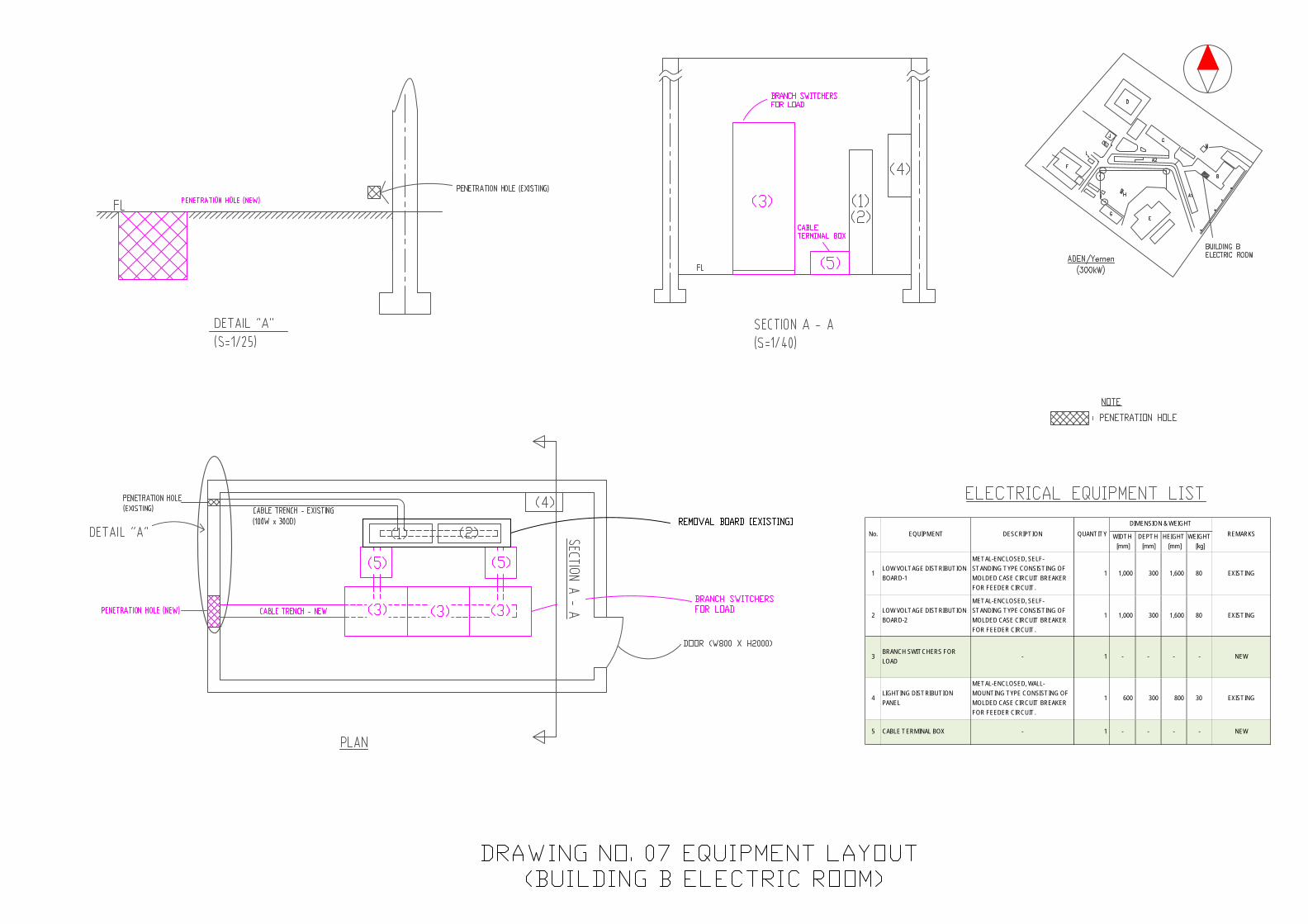
WIDTH [mm]
DEPTH [mm]
HEIGHT [mm]
WEIGHT [kg]
1LOW VOLTAGE DISTRIBUTIONBOARD-1
METAL-ENCLOSED, SELF-STANDING TYPE CONSISTING OFMOLDED CASE CIRCUIT BREAKERFOR FEEDER CIRCUIT .
1 1,000 300 1,600 80 EXISTING
2LOW VOLTAGE DISTRIBUTIONBOARD-2
METAL-ENCLOSED, SELF-STANDING TYPE CONSISTING OFMOLDED CASE CIRCUIT BREAKERFOR FEEDER CIRCUIT .
1 1,000 300 1,600 80 EXISTING
3BRANCH SWITCHERS FORLOAD
- 1 - - - - NEW
4LIGHTING DISTRIBUTIONPANEL
METAL-ENCLOSED, WALL-MOUNTING TYPE CONSISTING OFMOLDED CASE CIRCUIT BREAKERFOR FEEDER CIRCUIT .
1 600 300 800 30 EXISTING
5 CABLE TERMINAL BOX - 1 - - - - NEW
REMARKSEQUIPMENTNo. DESCRIPTIONDIMENSION & WEIGHT
QUANTITY

APPENDICES
1. MEMBER LIST OF THE STUDY TEAM
2. STUDY SCHEDULE
3. LIST OF PARTIES CONCERNED IN THE RECIPIENT COUNTRY
4. MINUTES OF DISCUSSIONS
5. SOFT COMPONENT (TECHNICAL ASSISTANCE) PLAN
6. REFERENCES

1. MEMBER LIST OF THE STUDY TEAM
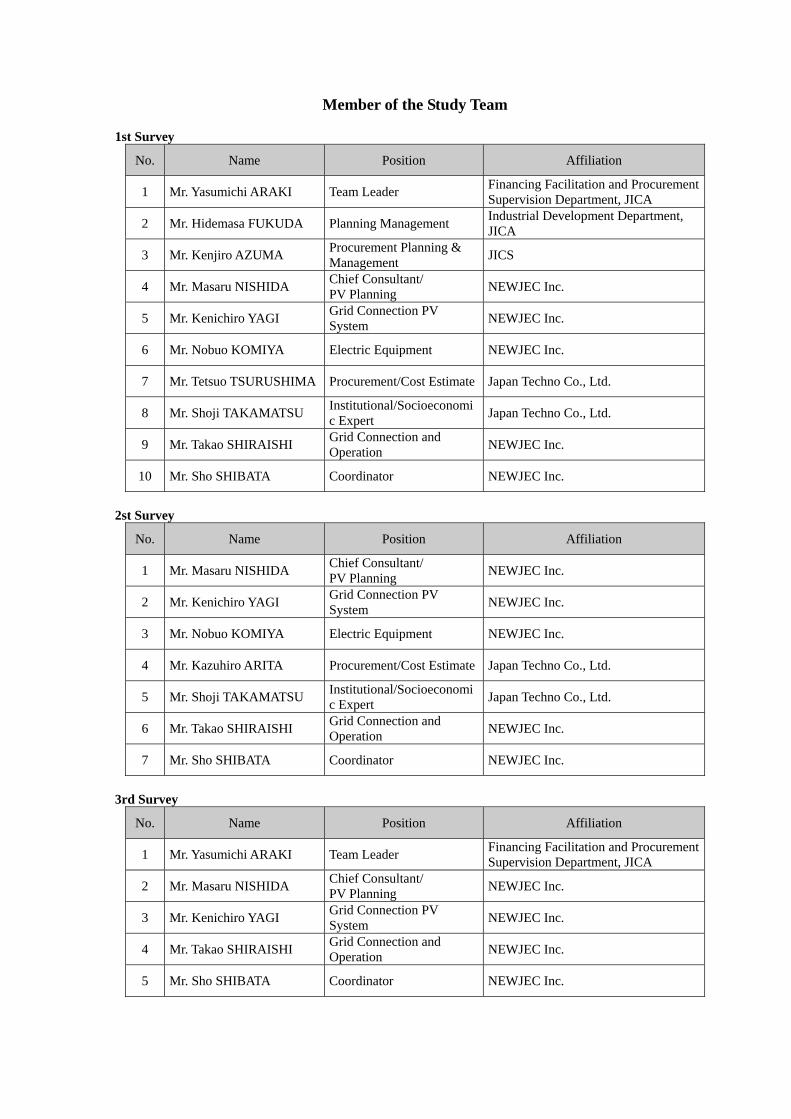
Member of the Study Team 1st Survey
No. Name Position Affiliation
1 Mr. Yasumichi ARAKI Team Leader Financing Facilitation and Procurement Supervision Department, JICA
2 Mr. Hidemasa FUKUDA Planning Management Industrial Development Department, JICA
3 Mr. Kenjiro AZUMA Procurement Planning & Management JICS
4 Mr. Masaru NISHIDA Chief Consultant/ PV Planning NEWJEC Inc.
5 Mr. Kenichiro YAGI Grid Connection PV System NEWJEC Inc.
6 Mr. Nobuo KOMIYA Electric Equipment NEWJEC Inc.
7 Mr. Tetsuo TSURUSHIMA Procurement/Cost Estimate Japan Techno Co., Ltd.
8 Mr. Shoji TAKAMATSU Institutional/Socioeconomic Expert Japan Techno Co., Ltd.
9 Mr. Takao SHIRAISHI Grid Connection and Operation NEWJEC Inc.
10 Mr. Sho SHIBATA Coordinator NEWJEC Inc.
2st Survey
No. Name Position Affiliation
1 Mr. Masaru NISHIDA Chief Consultant/ PV Planning NEWJEC Inc.
2 Mr. Kenichiro YAGI Grid Connection PV System NEWJEC Inc.
3 Mr. Nobuo KOMIYA Electric Equipment NEWJEC Inc.
4 Mr. Kazuhiro ARITA Procurement/Cost Estimate Japan Techno Co., Ltd.
5 Mr. Shoji TAKAMATSU Institutional/Socioeconomic Expert Japan Techno Co., Ltd.
6 Mr. Takao SHIRAISHI Grid Connection and Operation NEWJEC Inc.
7 Mr. Sho SHIBATA Coordinator NEWJEC Inc.
3rd Survey
No. Name Position Affiliation
1 Mr. Yasumichi ARAKI Team Leader Financing Facilitation and Procurement Supervision Department, JICA
2 Mr. Masaru NISHIDA Chief Consultant/ PV Planning NEWJEC Inc.
3 Mr. Kenichiro YAGI Grid Connection PV System NEWJEC Inc.
4 Mr. Takao SHIRAISHI Grid Connection and Operation NEWJEC Inc.
5 Mr. Sho SHIBATA Coordinator NEWJEC Inc.

2. STUDY SCHEDULE
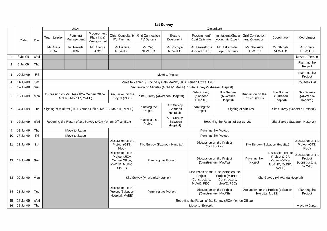
1st SurveyJICA
Team Leader PlanningManagement
ProcurementPlanning &
Management
Chief Consultant/PV Planning
Grid ConnectionPV System
ElectricEquipment
Procurement/Cost Estimate
Institutional/Socioeconomic Expert
Grid Connectionand Operation Coordinator Coordinator
Mr. ArakiJICA
Mr. FukudaJICA
Mr. AzumaJICS
Mr.NishidaNEWJEC
Mr. YagiNEWJEC
Mr. Komiya/NEWJEC
Mr. TsurushimaJapan Techno
Mr. TakamatsuJapan Techno
Mr. ShiraishiNEWJEC
Mr. ShibataNEWJEC
Mr. KimuraNEWJEC
1 8-Jul-09 Wed Move to Yemen
2 9-Jul-09 Thu Planning theProject
3 10-Jul-09 Fri Move to Yemen Planning theProject
4 11-Jul-09 Sat Move to Yemen / Courtesy Call (MoPIC, JICA Yemen Office, EoJ) Courtesy Call5 12-Jul-09 Sun Discussion on Minutes (MoPHP, MoEE) / Site Survey (Sabaeen Hospital)
6 13-Jul-09 Mon Discussion on Minutes (JICA Yemen Office,MoPIC, MoPHP, MoEE)
Discussion on theProject (PEC) Site Survey (Al-Wahda Hospital)
Site Survey (SabaeenHospital)
Site Survey (Al-WahdaHospital)
Discussion on theProject (PEC)
Site Survey (SabaeenHospital)
Site Survey (Al-WahdaHospital)
7 14-Jul-09 Tue Signing of Minutes (JICA Yemen Office, MoPIC, MoPHP, MoEE) Planning theProject
Site Survey (SabaeenHospital)
Planning theProject Signing of Minutes Site Survey (Sabaeen Hospital)
8 15-Jul-09 Wed Reporting the Result of 1st Survey (JICA Yemen Office, EoJ) Planning theProject
Site Survey (SabaeenHospital)
Reporting the Result of 1st Survey Site Survey (Sabaeen Hospital)
9 16-Jul-09 Thu Move to Japan Planning the Project10 17-Jul-09 Fri Move to Japan Planning the Project
11 18-Jul-09 SatDiscussion on the
Project (GTZ,PEC)
Site Survey (Sabaeen Hospital) Discussion on the Project(Constructors) Site Survey (Sabaeen Hospital)
Discussion on theProject (GTZ,
PEC)
12 19-Jul-09 Sun
Discussion on theProject (JICAYemen Office,
MoPHP, MoPIC,MoEE)
Planning the Project Discussion on the Project(Constructors, MoWE)
Planning theProject
Discussion on theProject (JICAYemen Office,
MoPHP, MoPIC,MoEE)
Discussion on theProject
(Constructors,MoWE)
13 20-Jul-09 Mon Site Survey (Al-Wahda Hospital)
Discussion on theProject
(Constructors,MoWE, PEC)
Discussion on theProject (MoPHP,
Constructors,MoWE, PEC)
Site Survey (Al-Wahda Hospital)
14 21-Jul-09 TueDiscussion on theProject (SabaeenHospital, MoEE)
Planning the Project Discussion on the Project(Constructors, MoWE)
Discussion on the Project (SabaeenHospital, MoEE)
Planning theProject
15 22-Jul-09 Wed Reporting the Result of 1st Survey (JICA Yemen Office)16 23-Jul-09 Thu Move to Ethiopia Move to Japan
Date Day
Consultant
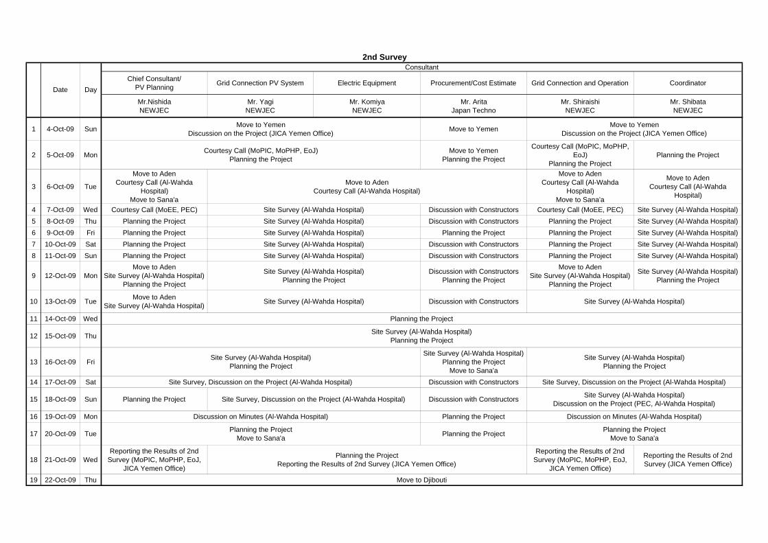
ConsultantChief Consultant/
PV Planning Grid Connection PV System Electric Equipment Procurement/Cost Estimate Grid Connection and Operation Coordinator
Mr.NishidaNEWJEC
Mr. YagiNEWJEC
Mr. KomiyaNEWJEC
Mr. AritaJapan Techno
Mr. ShiraishiNEWJEC
Mr. ShibataNEWJEC
1 4-Oct-09 Sun Move to YemenDiscussion on the Project (JICA Yemen Office) Move to Yemen Move to Yemen
Discussion on the Project (JICA Yemen Office)
2 5-Oct-09 Mon Courtesy Call (MoPIC, MoPHP, EoJ)Planning the Project
Move to YemenPlanning the Project
Courtesy Call (MoPIC, MoPHP,EoJ)
Planning the ProjectPlanning the Project
3 6-Oct-09 Tue
Move to AdenCourtesy Call (Al-Wahda
Hospital)Move to Sana'a
Move to AdenCourtesy Call (Al-Wahda Hospital)
Move to AdenCourtesy Call (Al-Wahda
Hospital)Move to Sana'a
Move to AdenCourtesy Call (Al-Wahda
Hospital)
4 7-Oct-09 Wed Courtesy Call (MoEE, PEC) Site Survey (Al-Wahda Hospital) Discussion with Constructors Courtesy Call (MoEE, PEC) Site Survey (Al-Wahda Hospital)5 8-Oct-09 Thu Planning the Project Site Survey (Al-Wahda Hospital) Discussion with Constructors Planning the Project Site Survey (Al-Wahda Hospital)6 9-Oct-09 Fri Planning the Project Site Survey (Al-Wahda Hospital) Planning the Project Planning the Project Site Survey (Al-Wahda Hospital)7 10-Oct-09 Sat Planning the Project Site Survey (Al-Wahda Hospital) Discussion with Constructors Planning the Project Site Survey (Al-Wahda Hospital)8 11-Oct-09 Sun Planning the Project Site Survey (Al-Wahda Hospital) Discussion with Constructors Planning the Project Site Survey (Al-Wahda Hospital)
9 12-Oct-09 MonMove to Aden
Site Survey (Al-Wahda Hospital)Planning the Project
Site Survey (Al-Wahda Hospital)Planning the Project
Discussion with ConstructorsPlanning the Project
Move to AdenSite Survey (Al-Wahda Hospital)
Planning the Project
Site Survey (Al-Wahda Hospital)Planning the Project
10 13-Oct-09 Tue Move to AdenSite Survey (Al-Wahda Hospital) Site Survey (Al-Wahda Hospital) Discussion with Constructors Site Survey (Al-Wahda Hospital)
11 14-Oct-09 Wed Planning the Project
12 15-Oct-09 Thu Site Survey (Al-Wahda Hospital)Planning the Project
13 16-Oct-09 Fri Site Survey (Al-Wahda Hospital)Planning the Project
Site Survey (Al-Wahda Hospital)Planning the Project
Move to Sana'a
Site Survey (Al-Wahda Hospital)Planning the Project
14 17-Oct-09 Sat Site Survey, Discussion on the Project (Al-Wahda Hospital) Discussion with Constructors Site Survey, Discussion on the Project (Al-Wahda Hospital)
15 18-Oct-09 Sun Planning the Project Site Survey, Discussion on the Project (Al-Wahda Hospital) Discussion with Constructors Site Survey (Al-Wahda Hospital)Discussion on the Project (PEC, Al-Wahda Hospital)
16 19-Oct-09 Mon Discussion on Minutes (Al-Wahda Hospital) Planning the Project Discussion on Minutes (Al-Wahda Hospital)
17 20-Oct-09 Tue Planning the ProjectMove to Sana'a Planning the Project Planning the Project
Move to Sana'a
18 21-Oct-09 WedReporting the Results of 2nd
Survey (MoPIC, MoPHP, EoJ,JICA Yemen Office)
Planning the ProjectReporting the Results of 2nd Survey (JICA Yemen Office)
Reporting the Results of 2ndSurvey (MoPIC, MoPHP, EoJ,
JICA Yemen Office)
Reporting the Results of 2ndSurvey (JICA Yemen Office)
19 22-Oct-09 Thu Move to Djibouti
2nd Survey
Date Day
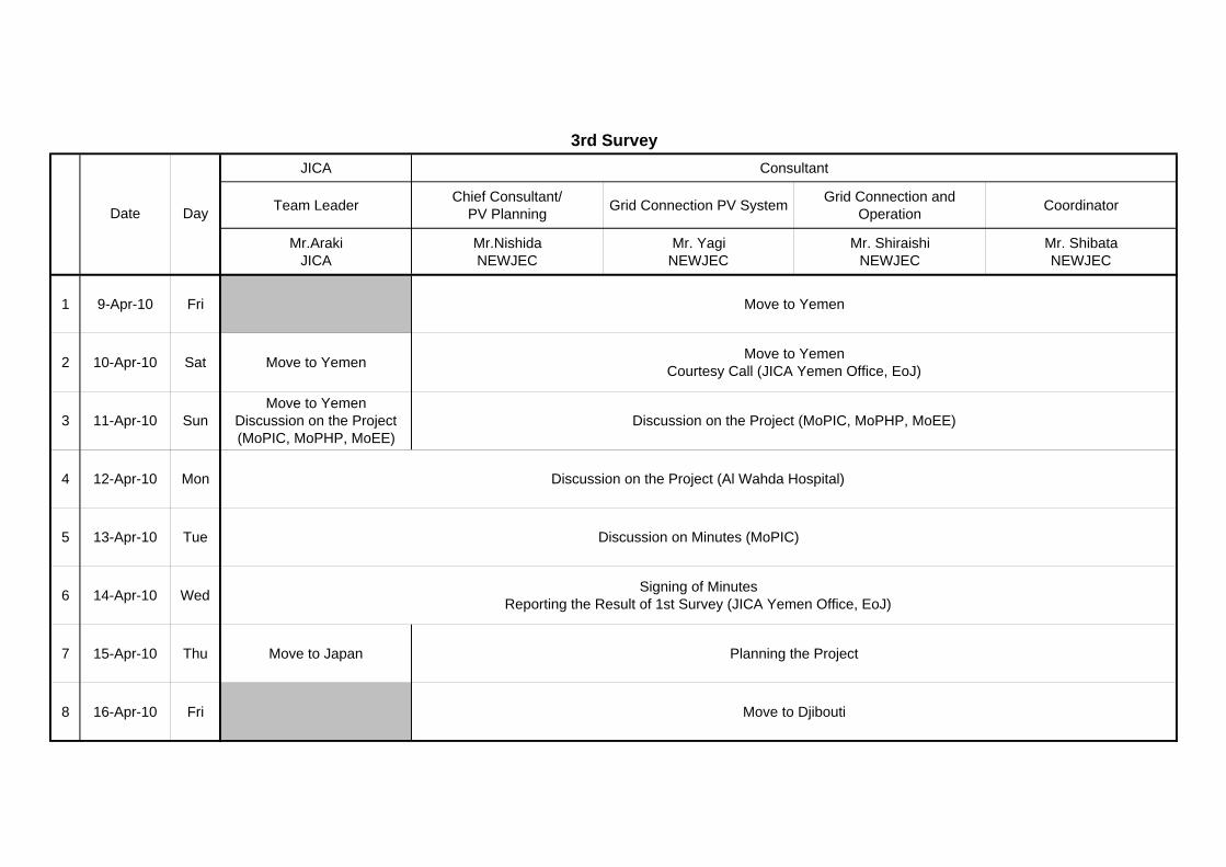
3rd SurveyJICA Consultant
Team Leader Chief Consultant/PV Planning Grid Connection PV System Grid Connection and
Operation Coordinator
Mr.ArakiJICA
Mr.NishidaNEWJEC
Mr. YagiNEWJEC
Mr. ShiraishiNEWJEC
Mr. ShibataNEWJEC
1 9-Apr-10 Fri Move to Yemen
2 10-Apr-10 Sat Move to Yemen Move to YemenCourtesy Call (JICA Yemen Office, EoJ)
3 11-Apr-10 SunMove to Yemen
Discussion on the Project(MoPIC, MoPHP, MoEE)
Discussion on the Project (MoPIC, MoPHP, MoEE)
4 12-Apr-10 Mon Discussion on the Project (Al Wahda Hospital)
5 13-Apr-10 Tue Discussion on Minutes (MoPIC)
6 14-Apr-10 Wed Signing of MinutesReporting the Result of 1st Survey (JICA Yemen Office, EoJ)
7 15-Apr-10 Thu Move to Japan Planning the Project
8 16-Apr-10 Fri Move to Djibouti
Date Day

3. LIST OF PARTIES CONCERNED IN THE RECIPIENT COUNTRY
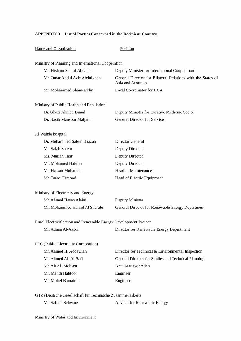
APPENDIX 3 List of Parties Concerned in the Recipient Country
Name and Organization Position
Ministry of Planning and International Cooperation
Mr. Hisham Sharaf Abdalla Deputy Minister for International Cooperation
Mr. Omar Abdul Aziz Abdulghani General Director for Bilateral Relations with the States of Asia and Australia
Mr. Mohammed Shamsaddin Local Coordinator for JICA
Ministry of Public Health and Population
Dr. Ghazi Ahmed Ismail Deputy Minister for Curative Medicine Sector
Dr. Nasib Mansour Maljam General Director for Service
Al Wahda hospital
Dr. Mohammed Salem Baazab Director General
Mr. Salah Salem Deputy Director
Ms. Marian Tahr Deputy Director
Mr. Mohamed Hakimi Deputy Director
Mr. Hassan Mohamed Head of Maintenance
Mr. Tareq Hamood Head of Electric Equipment
Ministry of Electricity and Energy
Mr. Ahmed Hasan Alaini Deputy Minister
Mr. Mohammed Hamid Al Sha’abi General Director for Renewable Energy Department
Rural Electricification and Renewable Energy Development Project
Mr. Adnan Al-Akori Director for Renewable Energy Department
PEC (Public Electricity Corporation)
Mr. Ahmed H. Addawlah Director for Technical & Environmental Inspection
Mr. Ahmed Ali Al-Safi General Director for Studies and Technical Planning
Mr. Ali Ali Mohsen Area Manager Aden
Mr. Mehdi Habtoor Engineer
Mr. Mohel Bamatref Engineer
GTZ (Deutsche Gesellschaft für Technische Zusammenarbeit)
Mr. Sabine Schwarz Adviser for Renewable Energy
Ministry of Water and Environment

Mr. Mahmoud M. Shidiwah Chairman
Mr. Helal Ali Al-Riashi Vice Director for Monitoring and Research
Mr. Salem Baquhaizel Director for EIA Department
Mr. Ameen Mohammed Al Hmadi Vice Director for Planning Department
Mr. Anwar NOAMAN Director for Climate Change Unit
Mr. Ali Al-Dobhani Director for Industrial Waste
Embassy of Japan in Yemen
Mr. Masakazu Toshikage Ambassador
Mr. Mitsunori Nanba Ambassador
Mr. Matahiro Yamaguchi Counselor
JICA Yemen Office
Mr. Takeshi Komori Resident Representative
Ms. Megumi Shuto Programme Formulation Advisor

4. MINUTES OF DISCUSSIONS
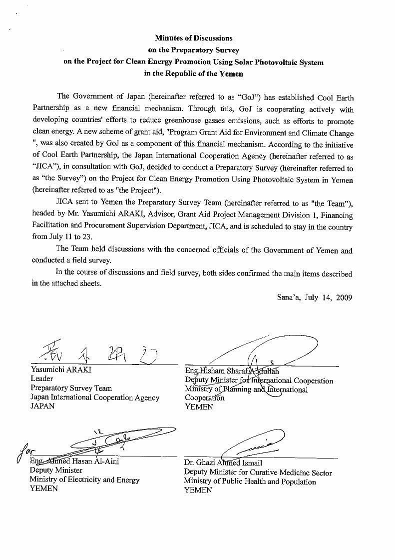

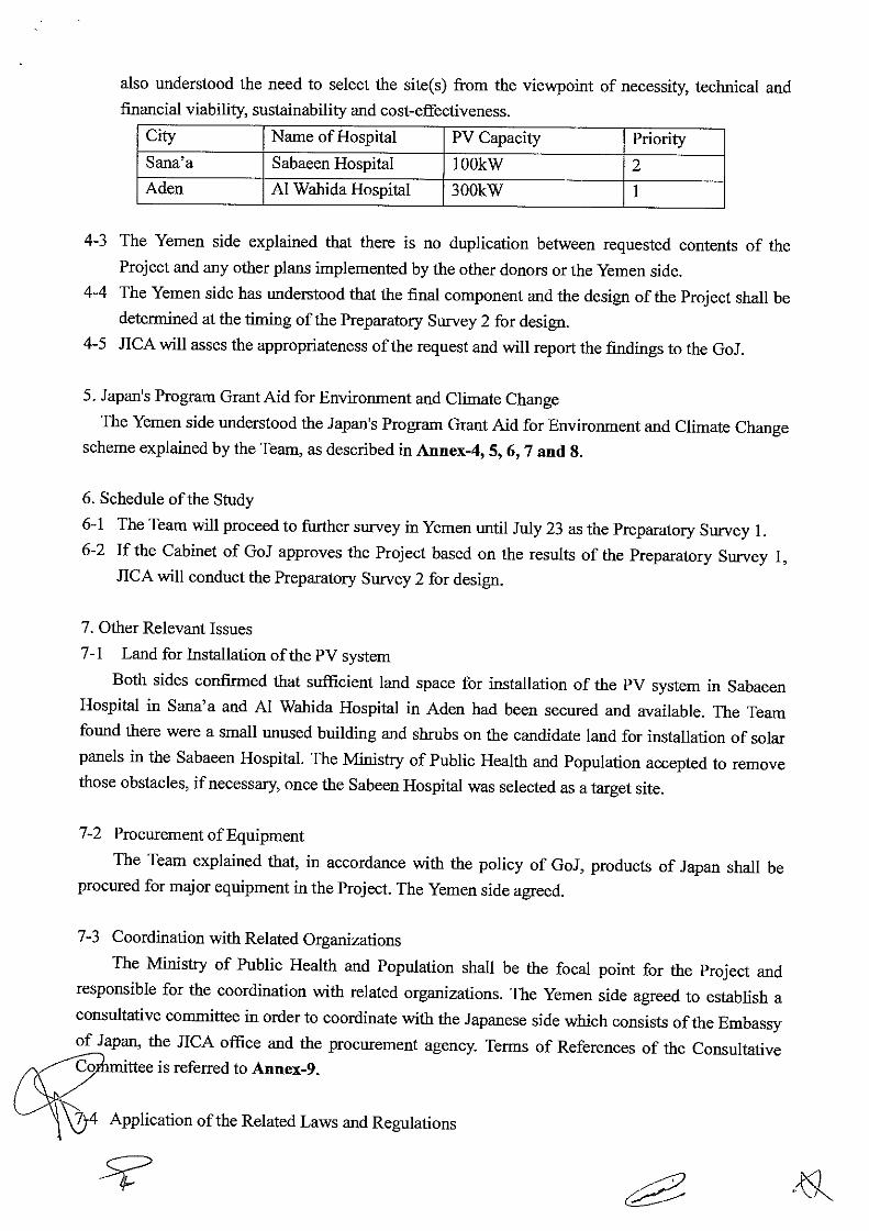
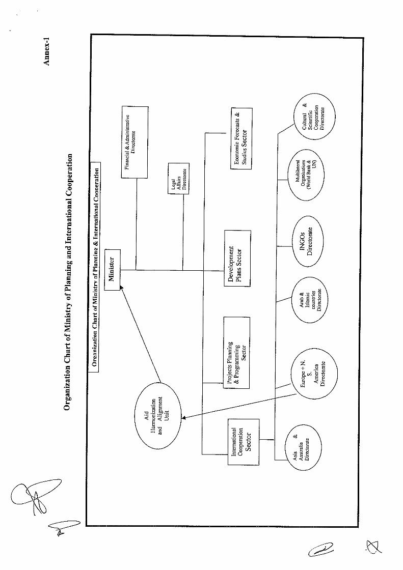
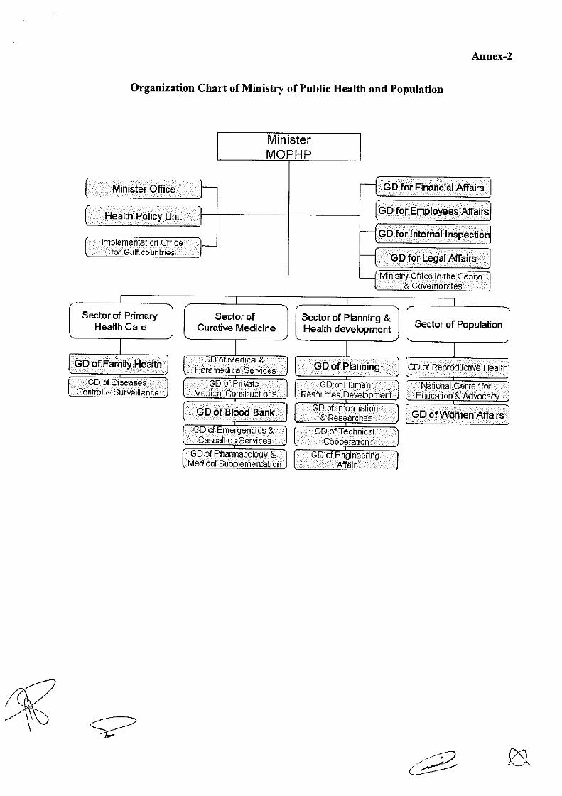
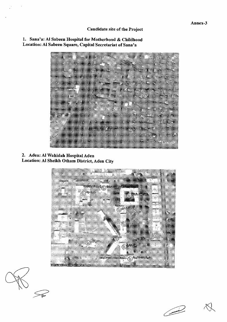


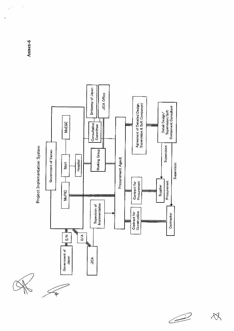
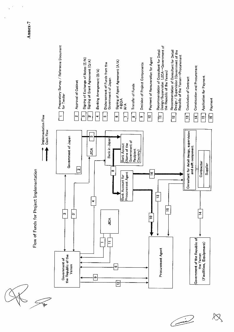
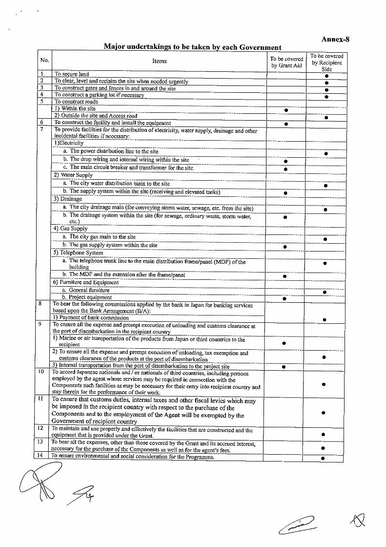
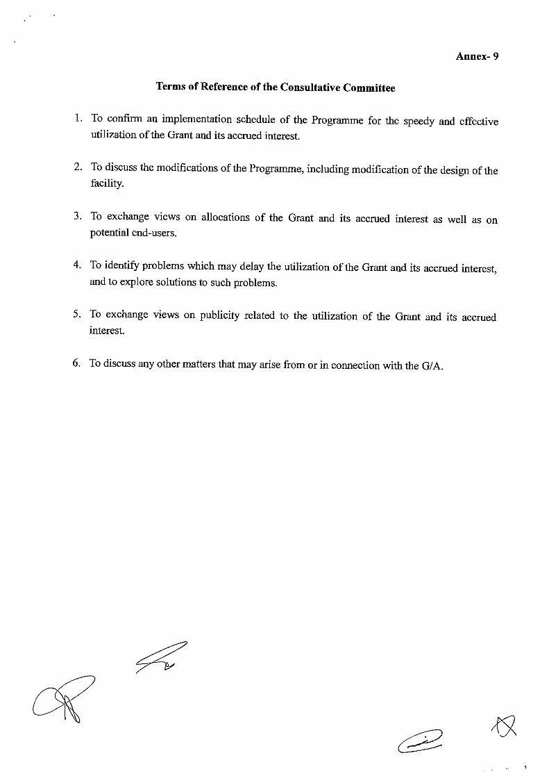

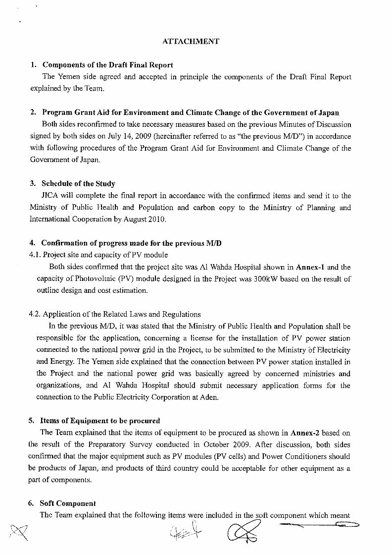


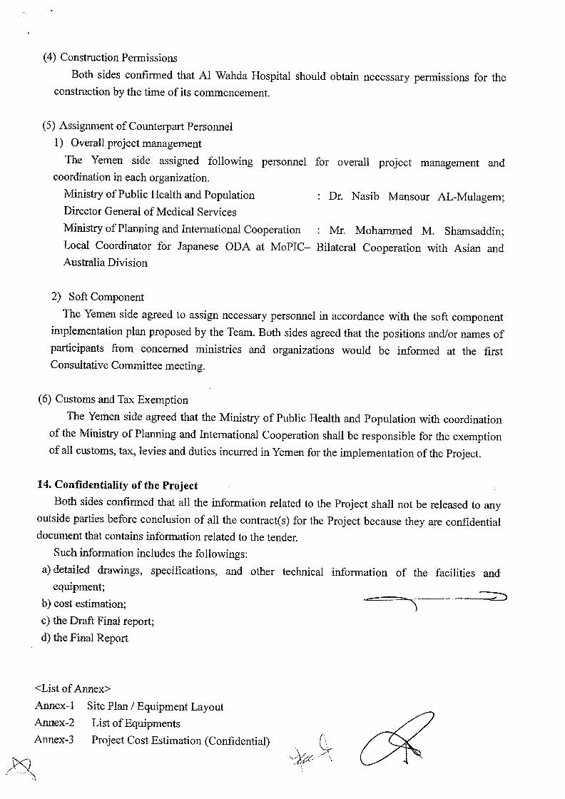
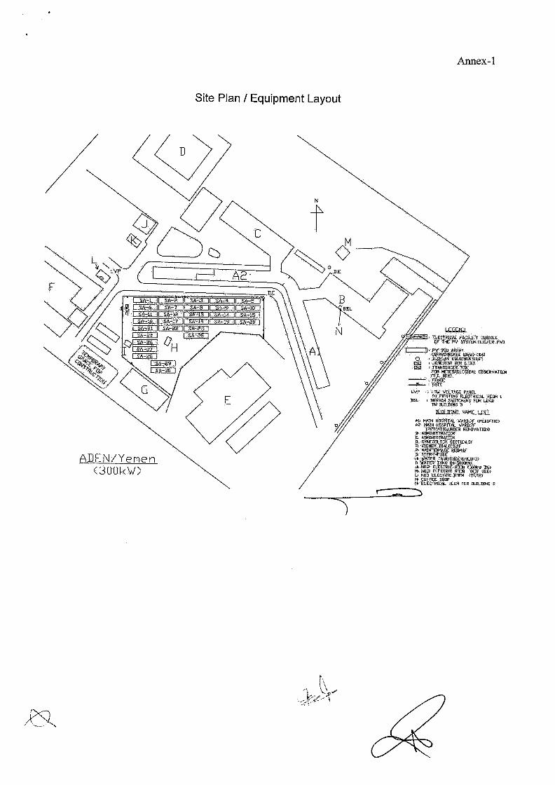
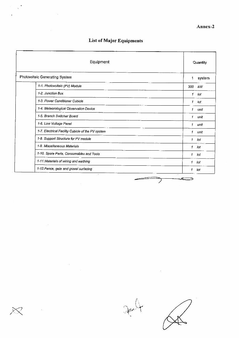
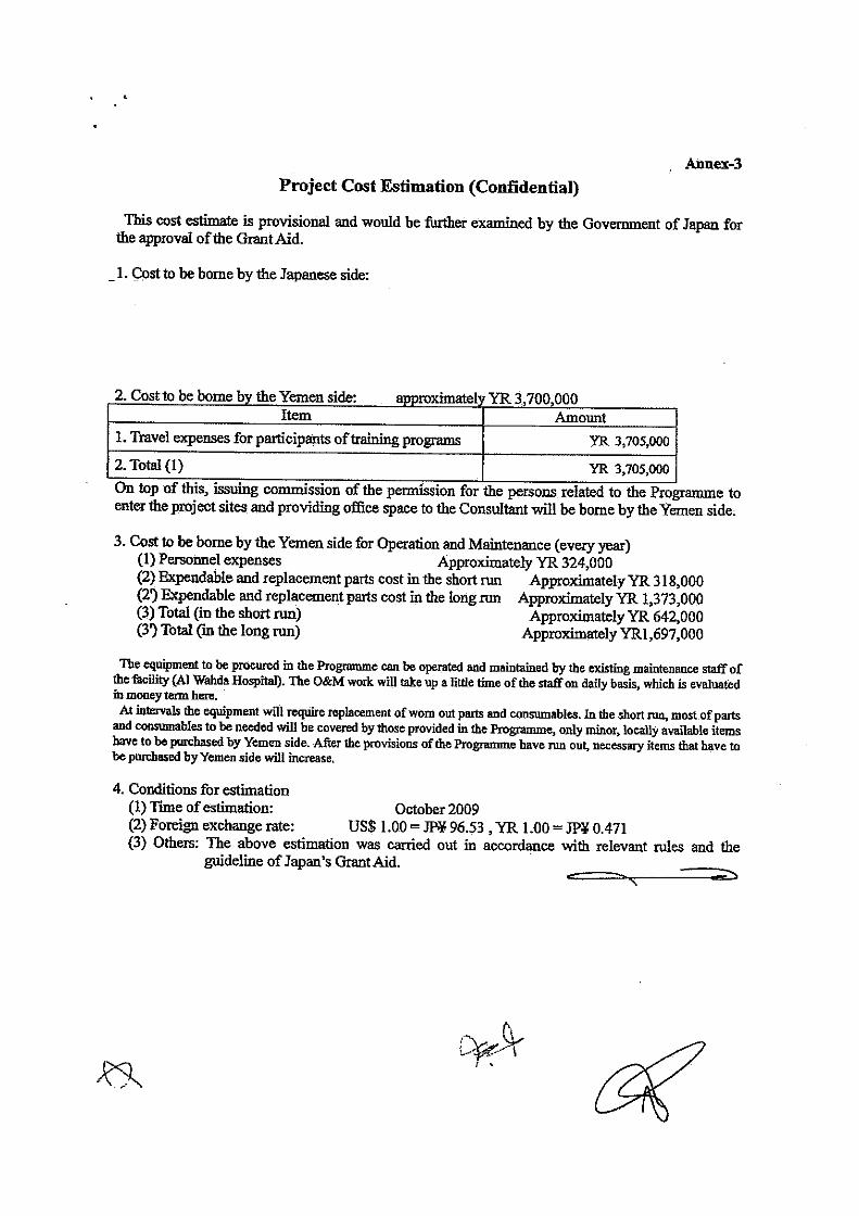

5. SOFT COMPONENT (TECHNICAL ASSISTANCE) PLAN
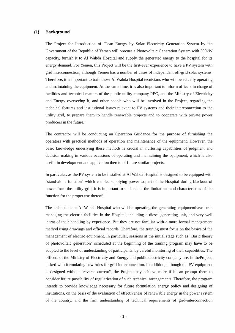
- 1 -
(1) Background
The Project for Introduction of Clean Energy by Solar Electricity Generation System by the
Government of the Republic of Yemen will procure a Photovoltaic Generation System with 300kW
capacity, furnish it to Al Wahda Hospital and supply the generated energy to the hospital for its
energy demand. For Yemen, this Project will be the first-ever experience to have a PV system with
grid interconnection, although Yemen has a number of cases of independent off-grid solar systems.
Therefore, it is important to train those Al Wahda Hospital tecnicians who will be actually operating
and maintaining the equipment. At the same time, it is also important to inform officers in charge of
facilities and technical matters of the public utility company PEC, and the Ministry of Electricity
and Energy overseeing it, and other people who will be involved in the Project, regarding the
technical features and institutional issues relevant to PV systems and their interconnection to the
utility grid, to prepare them to handle renewable projects and to cooperate with private power
producers in the future.
The contractor will be conducting an Operation Guidance for the purpose of furnishing the
operators with practical methods of operation and maintenance of the equipment. However, the
basic knowledge underlying these methods is crucial in nurturing capabilities of judgment and
decision making in various occasions of operating and maintaining the equipment, which is also
useful in development and application thereto of future similar projects.
In particular, as the PV system to be installed at Al Wahda Hospital is designed to be equipped with
"stand-alone function" which enables supplying power to part of the Hospital during blackout of
power from the utility grid, it is important to understand the limitations and characteristics of the
function for the proper use thereof.
The technicians at Al Wahda Hospital who will be operating the generating equipmenthave been
managing the electric facilities in the Hospital, including a diesel generating unit, and very well
learnt of their handling by experience. But they are not familiar with a more formal management
method using drawings and official records. Therefore, the training must focus on the basics of the
management of electric equipment. In particular, sessions at the initial stage such as "Basic theory
of photovoltaic generation" scheduled at the beginning of the training program may have to be
adopted to the level of understanding of participants, by careful monitoring of their capabilities. The
officers of the Ministry of Electricity and Energy and public electricity company are, in theProject,
tasked with formulating new rules for grid-interconnection. In addition, although the PV equipment
is designed without "reverse current", the Project may achieve more if it can prompt them to
consider future possibility of regularization of such technical arrangements. Therefore, the program
intends to provide knowledge necessary for future formulation energy policy and designing of
institutions, on the basis of the evaluation of effectiveness of renewable energy in the power system
of the country, and the firm understanding of technical requirements of grid-interconnection
- 2 -
including reverse current. At the same time, as PEC is given a role to technically support the
management activities conducted by the Hospital, he should be very well informed of the equipment
and workings of PV system.
The country has not had experience of interconnecting renewable energy generation to the national
power grid and the quality of electricity thereof is not quite stable or reliable. Therefore, the Project
proposes to require the Contractor to carry out three-month inspection after the commissioning of
the Products. Considering the plan that the training program will have to proceed with evaluation of,
and adoption to the capability of participants, it is very useful to take advantage of this occasion, to
carry out the revisory training programs at the same time, to build up the knowledge, to deepen it,
and to secure the sustainability of firm operation and maintenance techniques.
(2) Target of Training Program
To achieve the objectives of the training programs, the specific targets are set as below.
[ For operators of the equipment the Site ]
- To operate and maintain PV system under normal and emergency conditions, with sufficient
knowledge of the function of PV system in connection with the existing electric equipment in
the facility,
- To deal with the daily and periodical inspection and maintenance, fully understanding their
meaning and importance in the long run, and also able to change and procure the spare parts and
consumables,
- To consider routine activities of operation and maintenance and prepare an operation and
maintenance management plan,
- To be able to handle proper selection of loads and their arrangements at the destination of
Stand-alone function,
- To have basic knowledge that empowers them to give trainings to novice operators within and
outside the facility,
- To explain the system to the visitors using publicity leaflets prepared in the program.
[ For officials of the Ministry and public electric company ]
- To understand the PV system theories, technical characteristics, and institutional issues of
grid-interconnection,
- To have technical knowledge relevant in preparing agreements between private owners of power
generators and the public electric company,
- To acquire the knowledge for the development of future projects and guidance of new operation
and maintenance staff,
- To promote the use of PV using the publicity leaflets prepared in the program.
- 3 -
(3) Outcome of training programs - the operation and maintenance management plan has been established, and the PV system
procured is operated and maintained autonomously and sustainably,
- the Stand-alone function is properly and safely used with appropriate arrangement of loads at the
destination,
- O&M activities are followed up by using check sheets,
- Technical officers at the Ministry and PEC are equipped with knowledge on the method of
planning and on the institutional provisions for interconnection of renewable power generation
systems,
- Use of PV is being promoted using the publicity leaflets prepared in the program.
(4) Outcome confirmation and evaluation
Most tangible outcome will be the operation and maintenance management plan. The operation and
maintenance management plan is a plan to be made on the basis of manuals and guidance provided
by the Contractor, listing activities of O&M in short-term (daily activities), mid-term (a few months
to a few years) and long-term (seven years, an interval of long term maintenance), specifically
scheduling the activities, with check sheets for these activities, to make sure the activities are carried
out as planned and desired. As discussed below, the training programs are divided into two periods,
the first during the commissioning of the equipment and the other three months after the
commissioning. The operation and maintenance management plan will be drafted in the first-period
program and revised in the second, taking into account the actual experiences in three months.
Also, a trouble shooting manual is to be prepared in the training programs by participants. It is a
summary of operators' experiences, and responses sought in discussions in consultation with trainers.
The material prepared can be useful in evaluating the degree of understanding of basic knowledge,
and the process of preparation itself is helping the deepening of understanding. It also can be used in
similar projects elsewhere.
The exercises above are to be started by the discussion among the participants. After evaluating the
results, the lecturer joins the discussion, giving additional explanations and instructions as required.
Then the participants proceed with the tasks given. These three steps enable the lecturer to evaluate
the degree of understanding of the participants before and after the exercise sessions.
Publicity Leaflet will be designed and prepared in the programs, with due consideration to the
current status of renewable energy use in the recipient country, to be used and distributed to public
in order to introduce the PV system procured in the Project and to promote the use of renewable
energy.
Other outcomes in the first-period program will be evaluated in the following manners at the
- 4 -
beginning of the second-period program. The whole program will also be evaluated with the
materials presented at the Work Shop to be held at the end of the programs, further supplemented by
questionnaires.
- Evaluation of operation records and daily check sheets for three months,
- Evaluation of problem-response records for three months,
- Evaluation of communication and discussions in Trouble Shooting sessions in the
second-period program,
- Evaluation of knowledge acquisition concerning the system-wide management, through
Exercises, Workshop and its handouts prepared,
- A questionnaire conducted at end of the training programs
In preparing these questions, attentions should be paid to set particular questions and/or assignment
concerning the key topics of the programs, which enable to assess the effectiveness of the training.
(5) Planning of training programs
1) Contents
Training program is planned to consist of a series of lectures, exercises, and OJTs led by
Japanese consultants. The program is to be carried out in two separate periods; one during the
commissioning of the equipment, and the other three months after the commissioning.
There will also be O&M training provided by the Contractor of the Project. Therefore, the
consultant will coordinate with the Contractor and plan the details of his training program so that
the necessary techniques and knowledge are effectively transferred to the participants of the
program. Those training items with a symbol (*) below are the ones presumably provided by the
Contractor. The consultants will provide additional information for such items, if necessary, to
make them more relevant, not just "how to operate", in the context of understanding of PV
systems.
Before commissioning (approximately starting 4 weeks before commissioning)
Lectures on basic knowledge
- Basic theory of photovoltaic generation
- Utilization of photovoltaic generation
- Grid-interconnection and its planning
- Understanding surplus and reverse current
- Supply of power to Hospital from the grid
- Power demand and loads in Hospital
- Workings of PV equipment during blackout
- Stand-alone operation and protection functions
- 5 -
- Load management at the destination of Stand-alone mode power
- Planning PV systems
- Arrangement between PV owner and power utility
Lectures on construction planning
- Installation of PV equipment
- Power distribution in the facility
- Electric equipment in the facility and connection of PV system
- Scheduling works
- Work supervision and inspection, take-over
OJT program
- Witnessing connection works
- Witnessing pre-commissioning/commissioning tests
After commissioning of PV system (continued from "before commissioning " program)
Training provided by the Contractor
- Starting, stopping, restarting the system (*)
- Daily inspection and maintenance (*)
- Periodical inspection and maintenance (*)
- Consumables and replacement work (*)
- Occurrence of faults and actions (*)
Planning O&M works on the basis of Operation Manuals (exercises)
- Making daily check sheet/log sheet form
- Making failure/accident record form
- Maintaining PV equipment in a good condition
- Remedying problems occurred in stand-alone operation
- Making Operation and Maintenance Management Plan
For promotion of renewable energy use
- Design and preparation of publicity leaflet
It is very often experienced, in Japan and in other countries as well, that initial setting of the
equipment and/or the lack of familiarity of operation lead to malfunction or unsatisfying
performance of the equipment. Therefore, it is necessary to carry out revisory training program a
certain period after the commissioning. Initial malfunctions and poor operation practices
generally show up soon after the commissioning, but settle down as the countermeasures are
taken. It is not wise to leave them for too long without doing anything, while too short an
observation may overlook the problems or leave operators insufficient time and experiences.
Therefore, the revisory training program is proposed to take place soon after approximately three
month period since the commissioning, when certain experiences and operation records have
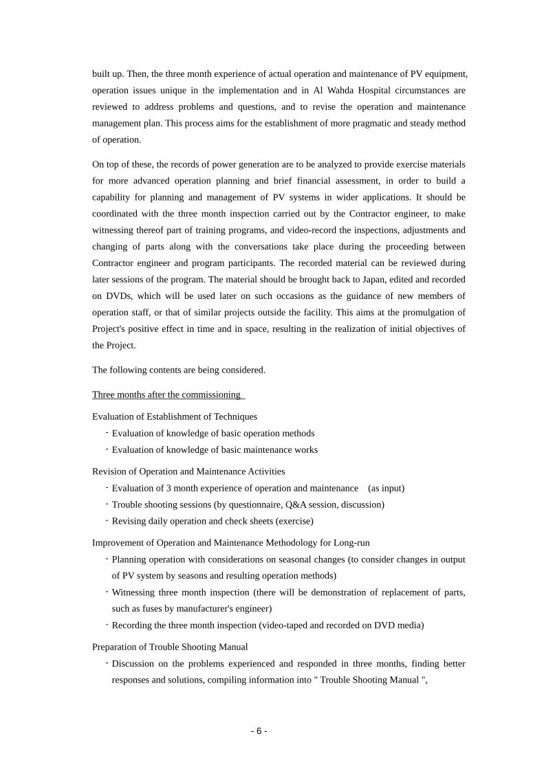
- 6 -
built up. Then, the three month experience of actual operation and maintenance of PV equipment,
operation issues unique in the implementation and in Al Wahda Hospital circumstances are
reviewed to address problems and questions, and to revise the operation and maintenance
management plan. This process aims for the establishment of more pragmatic and steady method
of operation.
On top of these, the records of power generation are to be analyzed to provide exercise materials
for more advanced operation planning and brief financial assessment, in order to build a
capability for planning and management of PV systems in wider applications. It should be
coordinated with the three month inspection carried out by the Contractor engineer, to make
witnessing thereof part of training programs, and video-record the inspections, adjustments and
changing of parts along with the conversations take place during the proceeding between
Contractor engineer and program participants. The recorded material can be reviewed during
later sessions of the program. The material should be brought back to Japan, edited and recorded
on DVDs, which will be used later on such occasions as the guidance of new members of
operation staff, or that of similar projects outside the facility. This aims at the promulgation of
Project's positive effect in time and in space, resulting in the realization of initial objectives of
the Project.
The following contents are being considered.
Three months after the commissioning
Evaluation of Establishment of Techniques
- Evaluation of knowledge of basic operation methods
- Evaluation of knowledge of basic maintenance works
Revision of Operation and Maintenance Activities
- Evaluation of 3 month experience of operation and maintenance (as input)
- Trouble shooting sessions (by questionnaire, Q&A session, discussion)
- Revising daily operation and check sheets (exercise)
Improvement of Operation and Maintenance Methodology for Long-run
- Planning operation with considerations on seasonal changes (to consider changes in output
of PV system by seasons and resulting operation methods)
- Witnessing three month inspection (there will be demonstration of replacement of parts,
such as fuses by manufacturer's engineer)
- Recording the three month inspection (video-taped and recorded on DVD media)
Preparation of Trouble Shooting Manual
- Discussion on the problems experienced and responded in three months, finding better
responses and solutions, compiling information into " Trouble Shooting Manual ",

- 7 -
Support for establishing advanced organization for operation and maintenance
- Brief financial assessment of the generation equipment (comparison of income and
expenses)
- Improvement of management of equipment for better financial performance of the
equipment,
- Planning better use of PV system responding to the increase in power demand,
Round up Exercises
- Revising the operation and maintenance management plan
- Questionnaire
Workshop
- Presenting revised operation and maintenance management plan and Trouble Shooting
Manual,
- Reporting results of brief financial assessment and operation records.
2) Participants
Candidate participants to the training sessions are as follows.
Al Wahda hospital technicians: Those who will be actually operating the PV system
PEC officers: in distribution, power purchasing or power plant
management related departments, with engineering
background (preferably having a degree in electric
engineering)
MEE, MPHP officials: in regulatory planning, facility management or facility
planning related departments, preferably with engineering
background
Other If there are requests from other ministries or organizations,
they may appoint persons in charge of public facility
planning and/or its maintenance to join the program.
Preliminary assignment for these participants is shown in the table below.
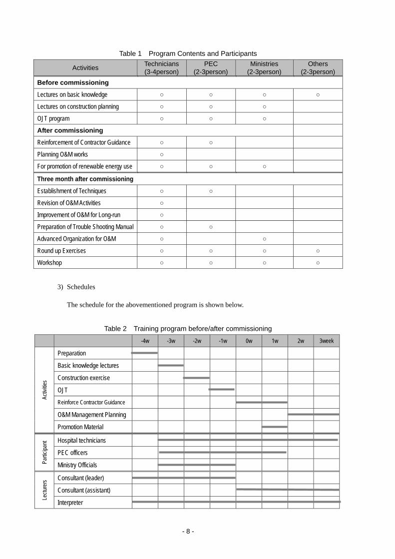
- 8 -
Table 1 Program Contents and Participants
Activities Technicians (3-4person)
PEC (2-3person)
Ministries (2-3person)
Others (2-3person)
Before commissioning
Lectures on basic knowledge ○ ○ ○ ○
Lectures on construction planning ○ ○ ○
OJT program ○ ○ ○
After commissioning
Reinforcement of Contractor Guidance ○ ○
Planning O&M works ○
For promotion of renewable energy use ○ ○ ○
Three month after commissioning
Establishment of Techniques ○ ○
Revision of O&M Activities ○
Improvement of O&M for Long-run ○
Preparation of Trouble Shooting Manual ○ ○
Advanced Organization for O&M ○ ○
Round up Exercises ○ ○ ○ ○
Workshop ○ ○ ○ ○
3) Schedules
The schedule for the abovementioned program is shown below.
Table 2 Training program before/after commissioning
-4w -3w -2w -1w 0w 1w 2w 3week
Activ
ities
Preparation
Basic knowledge lectures
Construction exercise
OJT
Reinforce Contractor Guidance
O&M Management Planning
Promotion Material
Partic
ipant Hospital technicians
PEC officers
Ministry Officials
Lectu
rers Consultant (leader)
Consultant (assistant)
Interpreter
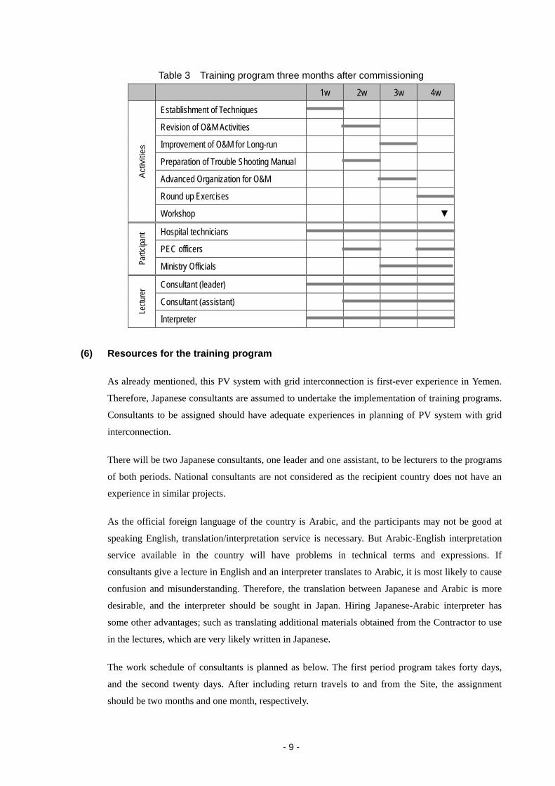
- 9 -
Table 3 Training program three months after commissioning
1w 2w 3w 4w
Act
iviti
es
Establishment of Techniques
Revision of O&M Activities
Improvement of O&M for Long-run
Preparation of Trouble Shooting Manual
Advanced Organization for O&M
Round up Exercises
Workshop ▼
Partic
ipant Hospital technicians
PEC officers
Ministry Officials
Lectu
rer Consultant (leader)
Consultant (assistant)
Interpreter
(6) Resources for the training program
As already mentioned, this PV system with grid interconnection is first-ever experience in Yemen.
Therefore, Japanese consultants are assumed to undertake the implementation of training programs.
Consultants to be assigned should have adequate experiences in planning of PV system with grid
interconnection.
There will be two Japanese consultants, one leader and one assistant, to be lecturers to the programs
of both periods. National consultants are not considered as the recipient country does not have an
experience in similar projects.
As the official foreign language of the country is Arabic, and the participants may not be good at
speaking English, translation/interpretation service is necessary. But Arabic-English interpretation
service available in the country will have problems in technical terms and expressions. If
consultants give a lecture in English and an interpreter translates to Arabic, it is most likely to cause
confusion and misunderstanding. Therefore, the translation between Japanese and Arabic is more
desirable, and the interpreter should be sought in Japan. Hiring Japanese-Arabic interpreter has
some other advantages; such as translating additional materials obtained from the Contractor to use
in the lectures, which are very likely written in Japanese.
The work schedule of consultants is planned as below. The first period program takes forty days,
and the second twenty days. After including return travels to and from the Site, the assignment
should be two months and one month, respectively.
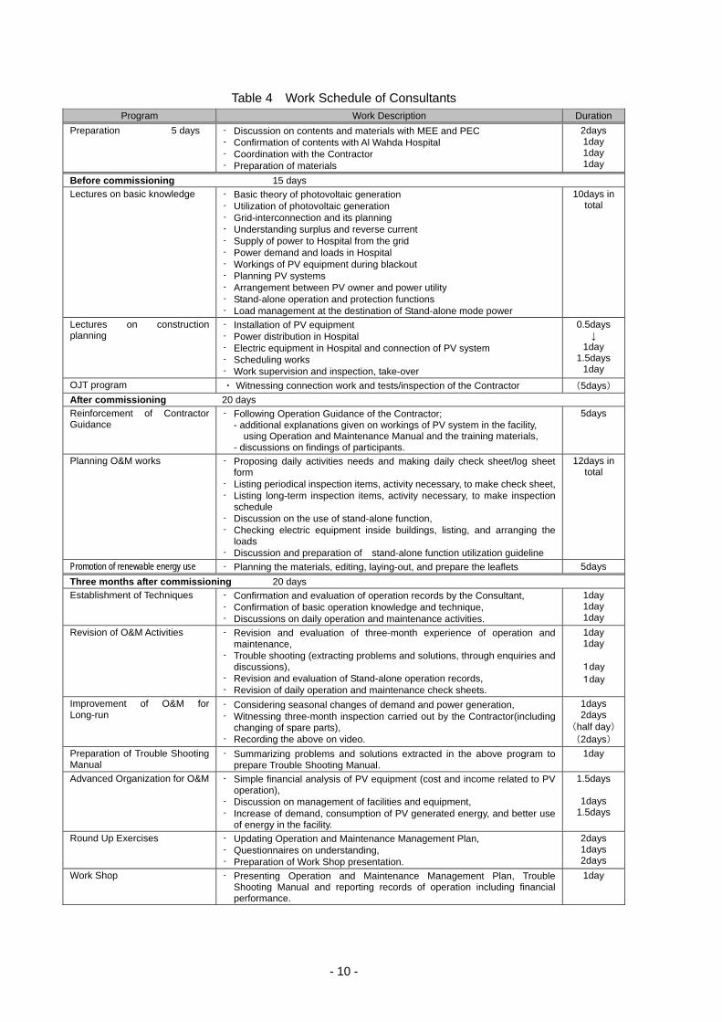
- 10 -
Table 4 Work Schedule of Consultants Program Work Description Duration
Preparation 5 days - Discussion on contents and materials with MEE and PEC - Confirmation of contents with Al Wahda Hospital - Coordination with the Contractor - Preparation of materials
2days 1day 1day 1day
Before commissioning 15 days Lectures on basic knowledge - Basic theory of photovoltaic generation
- Utilization of photovoltaic generation - Grid-interconnection and its planning - Understanding surplus and reverse current - Supply of power to Hospital from the grid - Power demand and loads in Hospital - Workings of PV equipment during blackout - Planning PV systems - Arrangement between PV owner and power utility - Stand-alone operation and protection functions - Load management at the destination of Stand-alone mode power
10days in total
Lectures on construction planning
- Installation of PV equipment - Power distribution in Hospital - Electric equipment in Hospital and connection of PV system - Scheduling works - Work supervision and inspection, take-over
0.5days ↓
1day 1.5days
1day OJT program ・ Witnessing connection work and tests/inspection of the Contractor (5days) After commissioning 20 days Reinforcement of Contractor Guidance
- Following Operation Guidance of the Contractor; - additional explanations given on workings of PV system in the facility, using Operation and Maintenance Manual and the training materials, - discussions on findings of participants.
5days
Planning O&M works - Proposing daily activities needs and making daily check sheet/log sheet form
- Listing periodical inspection items, activity necessary, to make check sheet, - Listing long-term inspection items, activity necessary, to make inspection
schedule - Discussion on the use of stand-alone function, - Checking electric equipment inside buildings, listing, and arranging the
loads - Discussion and preparation of stand-alone function utilization guideline
12days in total
Promotion of renewable energy use - Planning the materials, editing, laying-out, and prepare the leaflets 5days Three months after commissioning 20 days Establishment of Techniques - Confirmation and evaluation of operation records by the Consultant,
- Confirmation of basic operation knowledge and technique, - Discussions on daily operation and maintenance activities.
1day 1day 1day
Revision of O&M Activities - Revision and evaluation of three-month experience of operation and maintenance,
- Trouble shooting (extracting problems and solutions, through enquiries and discussions),
- Revision and evaluation of Stand-alone operation records, - Revision of daily operation and maintenance check sheets.
1day 1day
1day 1day
Improvement of O&M for Long-run
- Considering seasonal changes of demand and power generation, - Witnessing three-month inspection carried out by the Contractor(including
changing of spare parts), - Recording the above on video.
1days 2days
(half day)(2days)
Preparation of Trouble Shooting Manual
- Summarizing problems and solutions extracted in the above program to prepare Trouble Shooting Manual.
1day
Advanced Organization for O&M - Simple financial analysis of PV equipment (cost and income related to PV operation),
- Discussion on management of facilities and equipment, - Increase of demand, consumption of PV generated energy, and better use
of energy in the facility.
1.5days
1days 1.5days
Round Up Exercises - Updating Operation and Maintenance Management Plan, - Questionnaires on understanding, - Preparation of Work Shop presentation.
2days 1days 2days
Work Shop - Presenting Operation and Maintenance Management Plan, Trouble Shooting Manual and reporting records of operation including financial performance.
1day
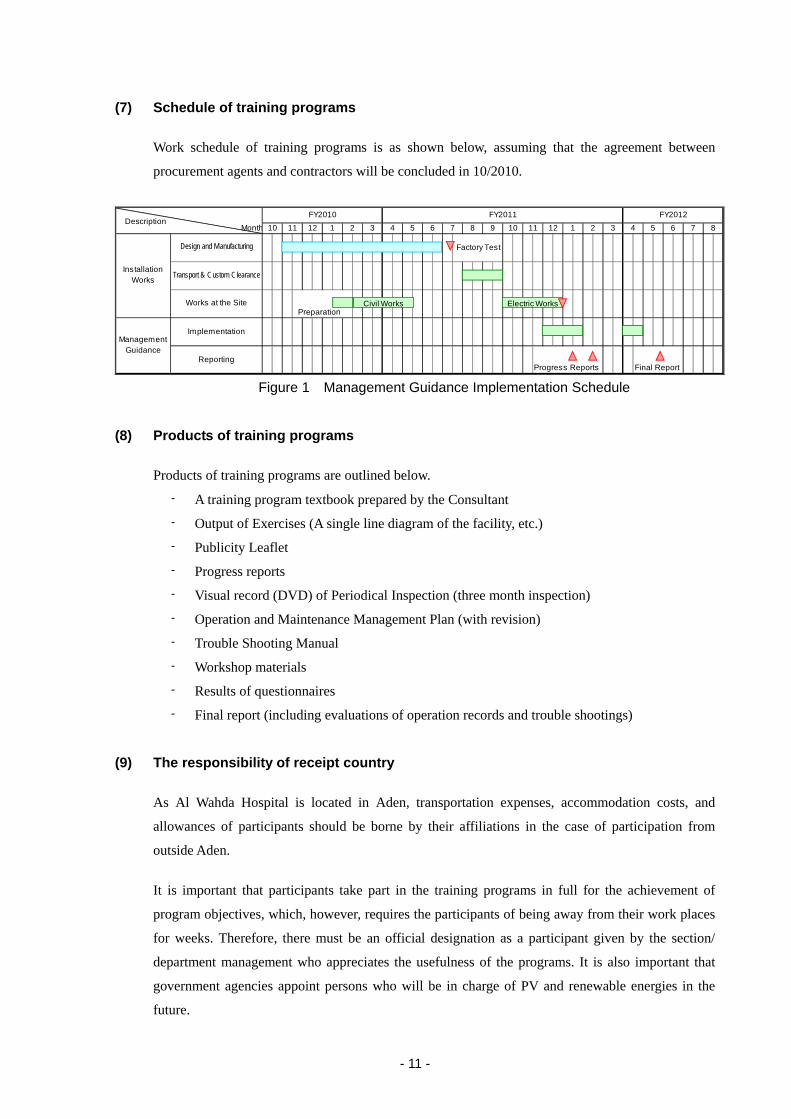
- 11 -
(7) Schedule of training programs
Work schedule of training programs is as shown below, assuming that the agreement between
procurement agents and contractors will be concluded in 10/2010.
Month
Factory Test
Transport & Custom Clearance
Preparation
Implementation
ReportingProgress Reports Final Report
FY2012FY2010 FY20111 2 3 410 12 9 10 11 125 6 7 8 5 6 7 81 2 3 411
ManagementGuidance
Works at the Site
InstallationWorks
Design and Manufacturing
Description
Civil Works Electric Works
Figure 1 Management Guidance Implementation Schedule
(8) Products of training programs
Products of training programs are outlined below.
- A training program textbook prepared by the Consultant
- Output of Exercises (A single line diagram of the facility, etc.)
- Publicity Leaflet
- Progress reports
- Visual record (DVD) of Periodical Inspection (three month inspection)
- Operation and Maintenance Management Plan (with revision)
- Trouble Shooting Manual
- Workshop materials
- Results of questionnaires
- Final report (including evaluations of operation records and trouble shootings)
(9) The responsibility of receipt country
As Al Wahda Hospital is located in Aden, transportation expenses, accommodation costs, and
allowances of participants should be borne by their affiliations in the case of participation from
outside Aden.
It is important that participants take part in the training programs in full for the achievement of
program objectives, which, however, requires the participants of being away from their work places
for weeks. Therefore, there must be an official designation as a participant given by the section/
department management who appreciates the usefulness of the programs. It is also important that
government agencies appoint persons who will be in charge of PV and renewable energies in the
future.

6. REFERENCES

6.1 Technical Notes for Draft Basic Design
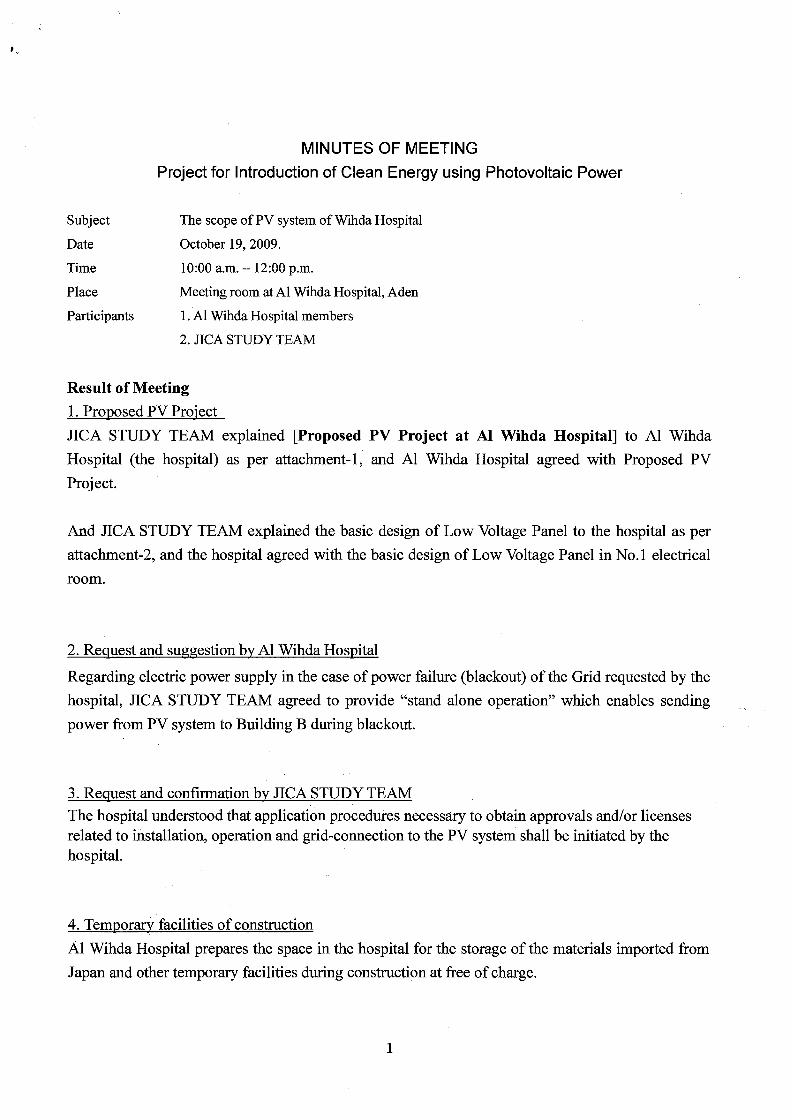
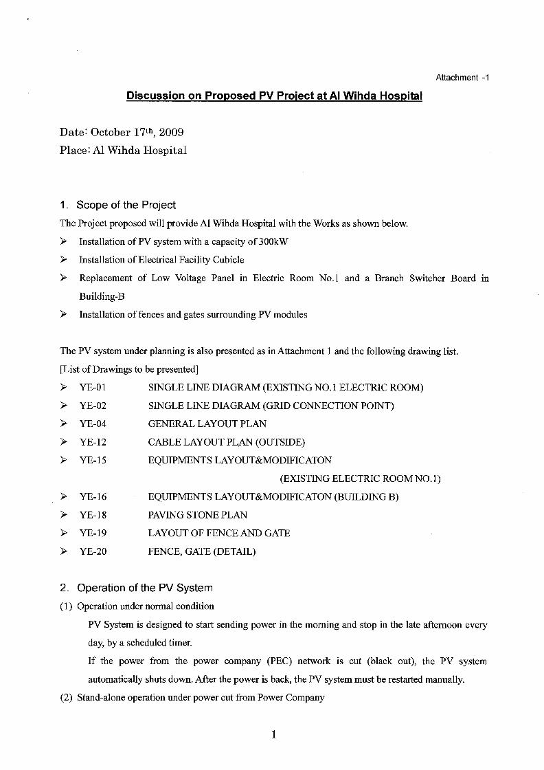


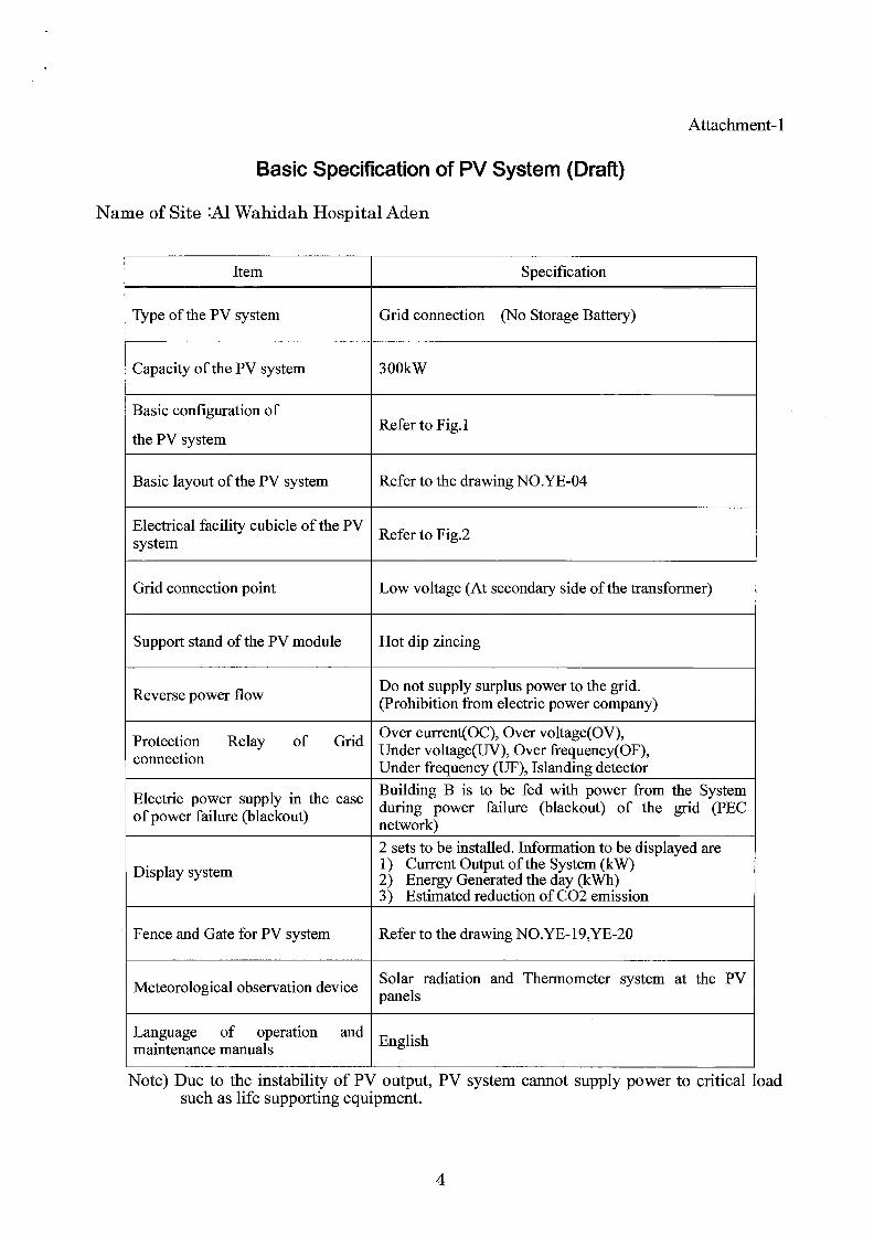
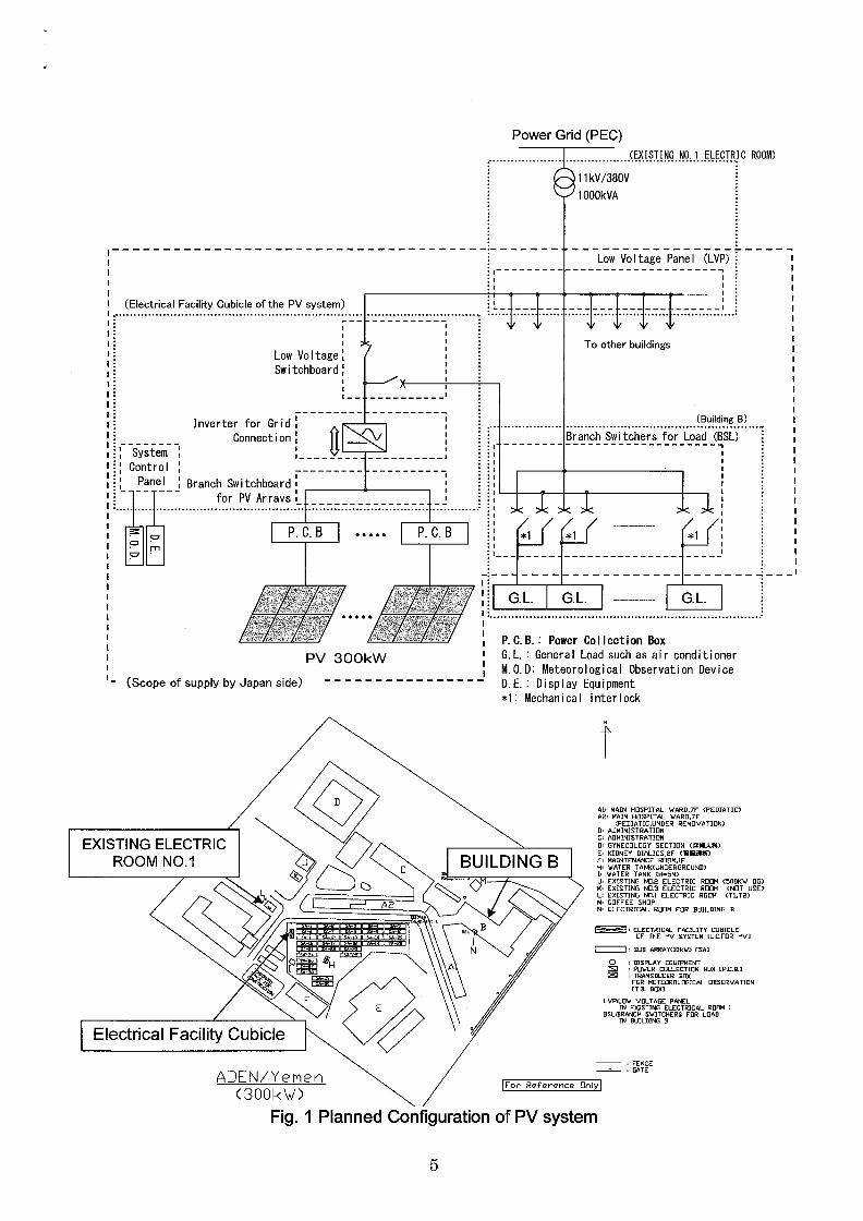
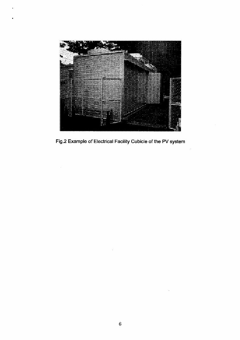

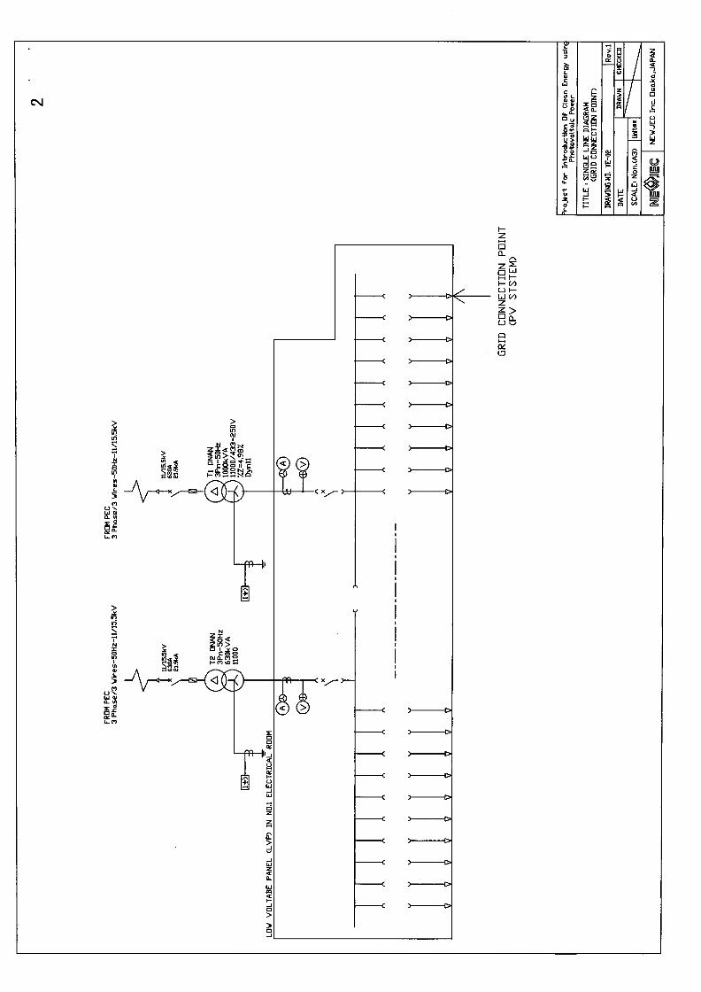
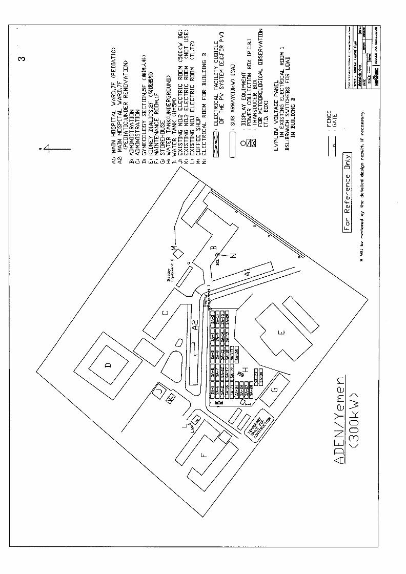
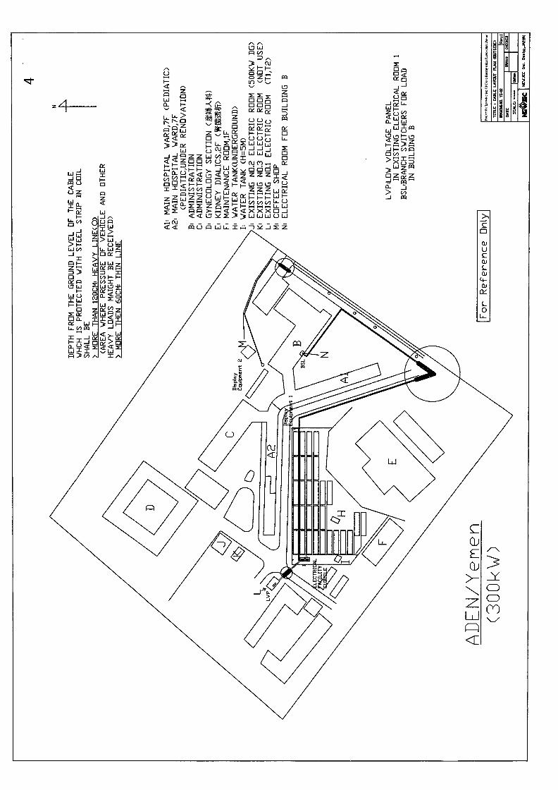


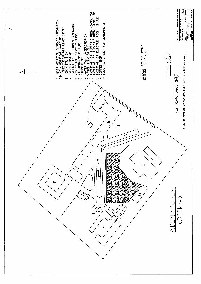
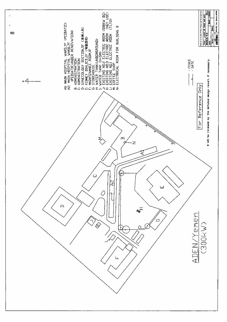
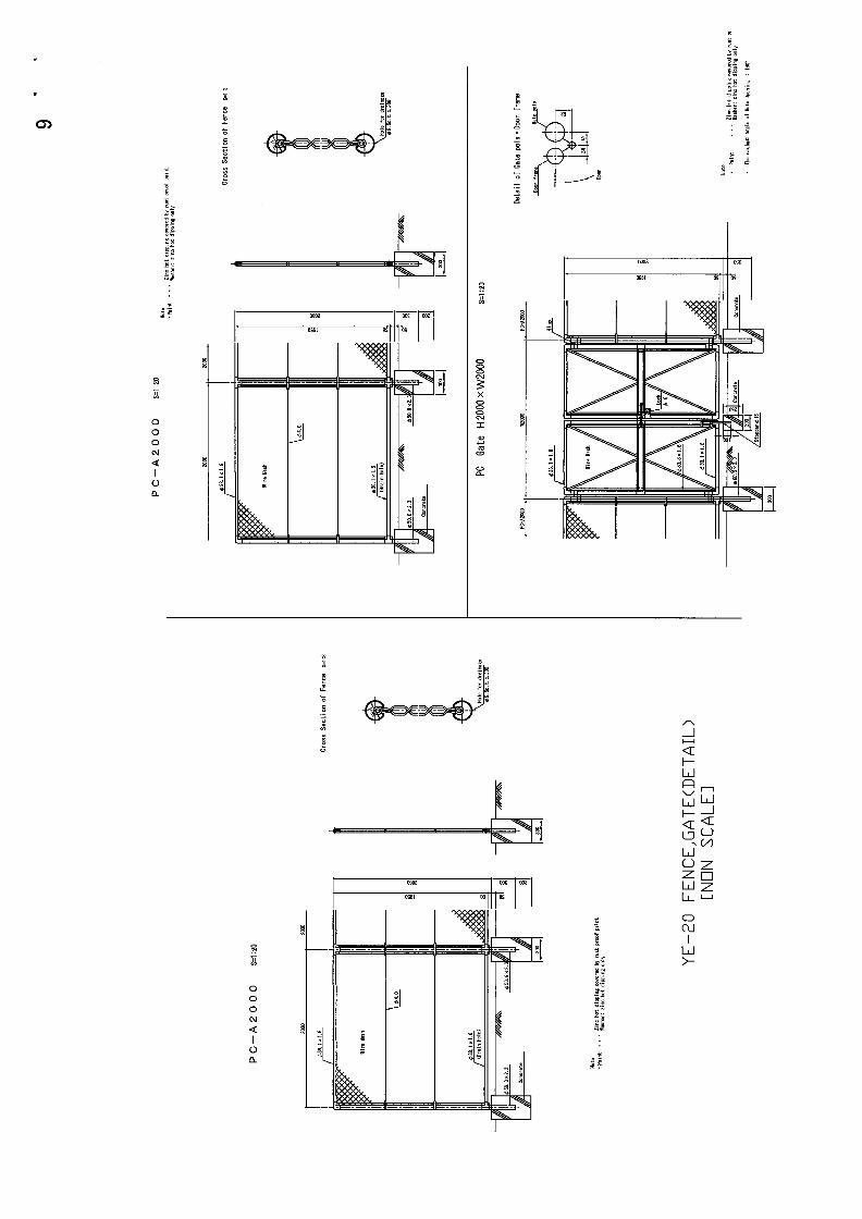
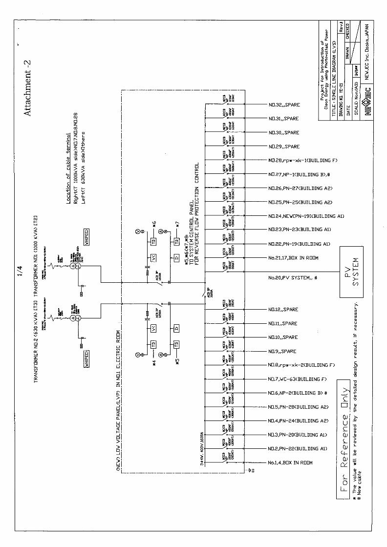
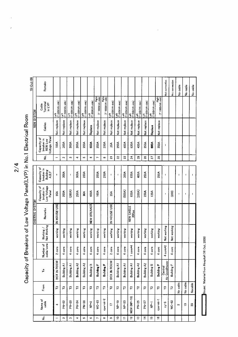
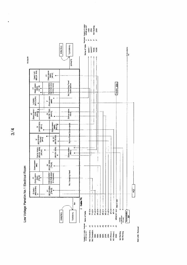
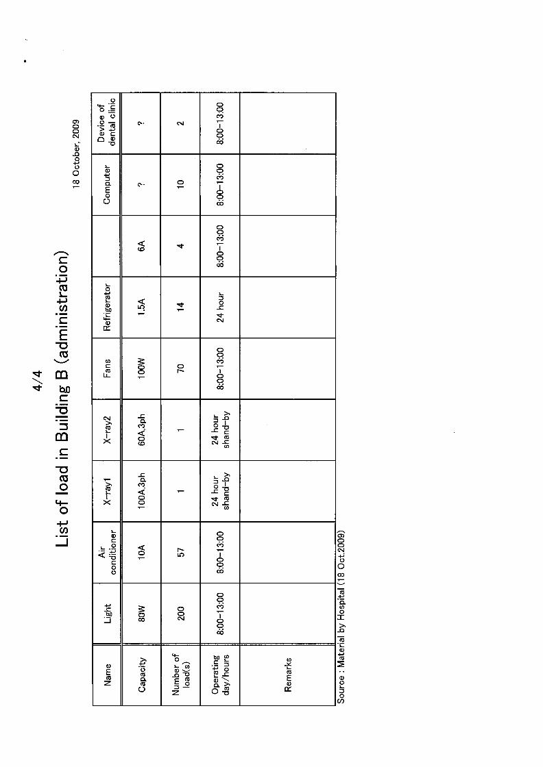

6.2 The Letter for Environmental Impact Assessment