final report experimental evaluation of the vem drive
TRANSCRIPT

VEM Drive
Doc: VEM-GWT-TN-1001
Issue: 1
Date: 5th March 2020
1
Final Report
Experimental Evaluation of the VEM Drive
Prepared by: M. Kößling, M. Weikert, M. Tajmar GWT-TUD
Accepted by: Prof. Dr. M. Tajmar GWT-TUD

VEM Drive
Doc: VEM-GWT-TN-1001
Issue: 1
Date: 5th March 2020
2
DOCUMENT CHANGE RECORD
Project: Experimental Results Reproduction Regarding the VEM Drive
Change Status Log:
Issue: CN No.: Class Reason for Change / Pages Affected
1
- - -
- - -
Initial Issue
Changes between the current and the previous issue are marked with a bar on the left side or deleted
Page Status Log: This Document comprises the following pages at issues shown:
Pages/Issue All pages – Issue 1

VEM Drive
Doc: VEM-GWT-TN-1001
Issue: 1
Date: 5th March 2020
3
Table of Contents
1 INTRODUCTION ................................................................................................... 4
2 EQUIPMENT ......................................................................................................... 5
2.1 VEM Drive ................................................................................................................................... 5 2.1.1 Mechanical Components 5
2.1.2 Electrical Components 6 2.1.3 Electrical Setup & Calibration 7
2.2 Thrust Balance v5 ...................................................................................................................... 9
2.3 Vacuum Chamber ..................................................................................................................... 10
3 TEST SETUP ....................................................................................................... 11
3.1 Setup 1 – Main Setup ............................................................................................................... 11
3.2 Setup 2 – Main Setup + Vacuum ............................................................................................. 11
3.3 Setup 3 – Main Setup + Shielding ........................................................................................... 11 3.3.1 Setup 3a - Metal Shielding 11 3.3.2 Setup 3b - Thermal Shielding 12
3.4 Setup 4 – 520 mm ..................................................................................................................... 13
3.5 Setup 5 – Angle 90° ................................................................................................................. 13
3.6 Setup 6 – Angle 15° ................................................................................................................. 13
3.7 Setup 7 – Main Setup + Antenna 2 .......................................................................................... 14
4 RESULTS ............................................................................................................ 15
4.1 Balance Calibration .................................................................................................................. 15
4.2 Force Measurements ............................................................................................................... 16
4.3 Voice Coil Influence Measurements ....................................................................................... 18
4.4 Additional Remarks ................................................................................................................. 19
5 CONCLUSION ..................................................................................................... 20
6 REFERENCES .................................................................................................... 21

VEM Drive
Doc: VEM-GWT-TN-1001
Issue: 1
Date: 5th March 2020
4
1 INTRODUCTION The VEM Drive (Variable-Electro-Magnetic Drive) is an invention by Space Warp Dynamics LLC that claims to distort space-time and thus creating an attractive force upon a target using frequencies in the VHF band. In their paper [1] they tested an antenna facing a torsion balance with different target materials. The balance used a wire of unknown material as a torsional spring and was housed inside a faraday cage and a plastic container. The deflection of the balance was measured using a laser that reflected from a mirror mounted on the balance. The antenna and the cage were in air. They mainly present swing rates of the balance (which is a useless measurement given the unknown wire of the balance). At the end, they present a couple of force values shown in Table 1. The target material and the distance between the drive and target is not specified for these values.
Power [W] Force [N]
175 0.63
375 0.71
650 1.25
Table 1: Force values for different power levels
This test campaign tries to replicate these results with a more accurate torsion balance at lower power levels. Two different VEM antenna were used. The antenna was put inside a large vacuum chamber to sufficiently shield any electromagnetic radiation to comply with regulations. A µN resolution (mostly metallic) thrust balance was used in order to measure thrust. A large non-metal POM plate, placed on the balance, was used as a target.

VEM Drive
Doc: VEM-GWT-TN-1001
Issue: 1
Date: 5th March 2020
5
2 EQUIPMENT In this section the equipment for the test campaign is described.
2.1 VEM Drive
This section describes the VEM Drive. It is split into two subsection. The first describes the antenna that is the VEM drive and its mounting stand. The second subsection describes all electrical components and the radio frequency (RF) setting used during the test campaign.
2.1.1 Mechanical Components
The VEM Drive itself consists of three main assemblies. The first is a fractal antenna made out of four copper coated aluminium plates (Figure 1a) – a second antenna with a rotated fractal configuration was tested too. Two plates are connected to one N-Type connector (one to the centre pin, the other to the shield).
a) Antennas screwed to the PTFE plates
b) Back side of VEM Drive
c) VEM Drive mounted on mounting stand
Figure 1: VEM Drive

VEM Drive
Doc: VEM-GWT-TN-1001
Issue: 1
Date: 5th March 2020
6
The second assembly consists of two polytetrafluoroethylene (PTFE) plates, each 5 mm thick. They are fixed to two Polyoxymethylene (POM) fixtures that combined assure an angle of 60° between the PTFE plates. The last two parts of this assembly are two bars with a thickness of 16 mm and a length of 487 mm (Figure 1b). The antenna assembly is mounted on the PTFE plates using nylon screws and nuts. The last assembly makes up the mounting stand for the VEM Drive. It consists of a 450 mm x 295 mm x 10 mm POM base plate with two Ø20 mm x 1000 mm POM rods glued to it. The rods have notches in it. The VEM drive is mounted to the stand via zip ties that fit into the notches of the rods (Figure 1c).
2.1.2 Electrical Components
To deliver electromagnetic power in the desired frequency- and power-range, a setting consisting of RF-commercial-of-the-shelf products was used. A matching circuit was designed and provided by Dr. Beukman. After analysing the antenna in our setup, a resonance frequency of 146 MHz was selected for all measurements. The following electronical and/or RF-components and devices were used: Rigol Frequency Generator DSG830 Frequency range: 9 kHz to 3 GHz; 0.01 Hz resolution Power level: -11 dBm to 13 dBm Connector: N-Type-50 Ω LAN controlled Minicircuits Amplifier ZHL-50W-52-S+ Frequency range: 50 MHz to 500 MHz Power level: Output 47 dbm; 50 W; gain 52 dB Connector: SMA-50 Ω Minicircuits Power detector ZX47-40LN-S+ Frequency range: 10 MHz to 8,000 MHz Frequency range: -50 dBm to +20 dBm Connector: SMA-50 Ω
Minicircuits Bi-Directional Coupler ZFBDC20-62HP+ Frequency range: 10 MHz to 600 MHz Power level: 47 dBm; 50 W Connector: SMA-50 Ω UIY Circulator CC6060A Frequency range: 136 MHz – 174 MHz Power level: 50 dBm; 100 W Connector: SMA-50 Ω

VEM Drive
Doc: VEM-GWT-TN-1001
Issue: 1
Date: 5th March 2020
7
Minicircuits Attenuators Frequency range: 0 MHz – 18,000 MHz Connector: SMA-50 Ω; N-Type-50 Ω Attenuation: BW-S40W20+ 40 dB @ 20 W; 43 dBm BW-N30W20+ 30 dB @ 20 W; 43 dBm BW-40N100W+ 40 dB @ 100 W; 50 dBm BW-S20W2+ 20 dB @ 2 W; 33 dBm Minicircuits 50Ω Coaxial Cables Frequency range: 0 MHz – 18,000 MHz Power level: min. 211 W @ 500 MHz Connectors: SMA & N-Type Measurement devices Anritsu MS46122A Dual Port Vector Network Analyser VNA for measuring reflected power to tune the matching device to minimum reflected power. Seeedstudio RF Explorer 3G Spectrum Analyser for validating generated frequency and to compare radiation level to other RF sources.
2.1.3 Electrical Setup & Calibration
First the emitter was placed and aligned inside of the vacuum chamber 1130 mm next to the thrust balance with its POM target. The emitter antenna was connected to two coaxial N-Type-cables and so to a signal-splitter/combiner which was also provided with the emitter antenna. A SMA-N-Type-adapter connected the splitter/combiner to a coaxial cable (36”) leading to the (floating) SMA-coaxial vacuum chamber feedthrough. Here the RF-behavior of the emitter and power leading cables was determined with the calibrated VNA.
Figure 2: Electrical configuration 1

VEM Drive
Doc: VEM-GWT-TN-1001
Issue: 1
Date: 5th March 2020
8
Now the matching device was connected with a coaxial cable to the outside of the SMA-coaxial vacuum-chamber feedthrough. Then, the VNA was connected to the input port of the matching device and the reflected power was minimized by tuning the devices capacitors with use of a Smith-chart-visualization. For first calibration measurements, the matching circuit was now connected as seen in configuration 1 (Figure 2). Configuration 1 consisted of a frequency generator, a RF-amplifier, a circulator (with attached 40 dB-attenuator and power detector to protect the amplifier from reflected power), a bi-directional-coupler (with attenuators and power detectors to measure input and reflected power), the matching device and connecting cables. The frequency generator was controlled via Ethernet connection with a laboratory computer and the power detectors were read out with a Labjack T7 device connected via USB to the same laboratory computer. The thrust balance was controlled by this computer as well. A Labview program allowed signal commanding, receiving and processing as well as statistical analysis of the input and output data. Early measurement runs showed a difference between the commanded and the measured power which lead to a verification with a 20 W/40 dB attenuator and a termination instead of matching device and emitter antenna. Also the behavior of the used power detectors was validated and the control algorithm was adapted. Nevertheless, inconsistent power detector signals were measured at power levels above 20 W. To avoid this effects, the power detector for reflected power was replaced with a 50 Ω-termination which lead to even worse power measurements. Configuration 2 (Figure 3) did not use the bi-directional coupler, because it was assumed, that the change in wave impedance due to thermal shifts led to unclear false-signals. This new configuration only measured the reflected power coming back from the emitter antenna.
Figure 3: Electrical configuration 2
To verify the input power, the matching device and emitter were replaced with a 100 W/40 dB attenuator and an attached power detector. This matched load showed the commanded and amplified power with only a small difference to the expected power. This configuration 2 was used throughout all tests. During measurements at different power levels, the radiated RF-signal outside of the vacuum chamber was measured with a spectrum analyzer.

VEM Drive
Doc: VEM-GWT-TN-1001
Issue: 1
Date: 5th March 2020
9
Impedance matching was validated via VNA after measurement sequences and was adjusted if changes in the experimental setting were made (add FSX shield, add wire mesh).
2.2 Thrust Balance v5
The thrust balance (Figure 4), a so-called torsion balance, is described in reference [2] in detail. It uses two E-20 pivots by C-Flex as a torsional spring in the center, has an eddy current brake used to damp the oscillation and a voice coil to calibrate the balance. Furthermore, the bottom pivot is mounted on a rotational motor that can apply a torque onto this pivot that changes the resting position of the balance. This is used to align the voice coil, even if the balance is inside a vacuum chamber. For this test campaign, the shielding plates of the experiment box were removed and a target, made out of POM, weighing 620 g, was placed on it instead. The electronics box underwent no changes.
Figure 4: Torsion balance v5 [2]
The voice coil is used to produce a defined force, which is independent of the actual balance position (within a certain range of a few millimeters). This is used to actually calibrate the balance: A defined force causes a deflection of the balance, which is then further used to determine arbitrary forces. Such a voice coil is shown in Figure 5. It consists of a housing with a permanent magnet in the middle (mounted on the balance arm) and a moveable coil. This coil is connected to a precision power supply and produces a defined force proportional to the applied current. As we will see later, this coil can pick of electromagnetic radiation and cause anomalous force measurements.

VEM Drive
Doc: VEM-GWT-TN-1001
Issue: 1
Date: 5th March 2020
10
Figure 5: Voice-Coil (left, Bei-Kimco) and Schematic (right, www.powertransmission.com)
2.3 Vacuum Chamber
The VEM Drive as well as the torsion balance were placed inside a vacuum chamber with the dimensions of 2.5 m in length, 1.2 m in width and 1.5 m in height. The chamber has 14 ISO-K view ports that are covered with tin foil to dampen the RF signal of the antenna, leaving the chamber. Additionally, numerous flanges of different size are available. Two KF40 flanges are used for the RF and the interferometer feedthrough respectively and one CF63 flange supports two SubD 25 connectors used to connect the balance with its control instruments and computer. To create a vacuum, a roots pump ECO 3-65+ and a cryo pump CoolVAC iCL by Leybold are connected to the chamber. The pressure is read with a Pfeiffer PKR 361 gauge. The scroll pump can reach a vacuum of 10-3 mbar and the cryo pump 10-8 mbar, given sufficient time.

VEM Drive
Doc: VEM-GWT-TN-1001
Issue: 1
Date: 5th March 2020
11
3 TEST SETUP This section describes the different experimental setups performed during the test campaign. Seven different setups were built to determine a possible influence from air, RF-/thermal radiation, distance between antenna and target, angle of attack and antenna configuration.
3.1 Setup 1 – Main Setup
Setup 1 (Figure 6) consists of antenna 1, its mounting platform, the torsion balance and the POM target. The antenna is fixed to the platform via zip ties. The distance between the POM target and the root of the antenna amounts to 1130 mm. The antennas root also has a distance of 260 mm to the side of the vacuum chamber and 882 mm to the back. The center of the target, as well as the center of the antenna is 430 mm above the floor of the chamber.
a) Schematics
b) Actual setup
Figure 6: Setup 1 – main setup
3.2 Setup 2 – Main Setup + Vacuum
Setup 2 was done to determine a possible influence of air. In low pressure environments, air movement caused by convection is mitigated. It is exactly the same as setup 1, except the vacuum chamber is evacuated and has a pressure of 2.1 x 10⁻⁶ mbar.
3.3 Setup 3 – Main Setup + Shielding
Setup 3a and 3b was done to determine, if a possible effect can be destroyed by shielding the antenna from the target on the torsion balance.
3.3.1 Setup 3a - Metal Shielding
Setup 3a (Figure 7) introduces a steel grid between the antenna and the torsion balance. The remaining holes between the grid and the vacuum chamber are covered with tin foil. The grid consists of steel wires with a diameter of 0.06 mm and a mesh size of 0.6 mm. The tin foil is taped to the grid and the walls of the chamber with Kapton tape to ensure an electrical connection.
y
Vacuum Chamber
882
260 VEM Antenna
Balance
2500
POM Target
1130
Torsion-
1200

VEM Drive
Doc: VEM-GWT-TN-1001
Issue: 1
Date: 5th March 2020
12
Figure 7: Setup 3a – metal shielding with steel grid + tin foil
3.3.2 Setup 3b - Thermal Shielding
Setup 3b (Figure 8) consists of an extruded polystyrene plate (also called XPS, or styrodur) between the antenna and the balance. XPS has a low thermal conductivity and can shield the balance from potential thermal radiation from the antenna. The plate is not large enough to separate the antenna and the balance completely.
a) Front view
b) Rear view
Figure 8: Setup 3a – thermal shielding with XPS

VEM Drive
Doc: VEM-GWT-TN-1001
Issue: 1
Date: 5th March 2020
13
3.4 Setup 4 – 520 mm
In setup 4 the distance between the antennas root and the target on the balance is lowered to 520 mm. This is achieved by moving the balance closer to the antenna. The antenna itself is not moved, to avoid changing the RF-configuration of the cables and antenna itself.
3.5 Setup 5 – Angle 90°
Setup 5 (Figure 9) has the antenna rotated 90° so it is facing the side wall of the vacuum chamber. Due to the long and stiff cables, connecting the antenna and the splitter, the antennas root changed its position. It is 329 mm away from the wall of the chamber and 795 mm from the back. The distance to the balance changed as well to 607 mm.
a) Schematics
b) Actual setup
Figure 9: Setup 5 – antenna turned 90°
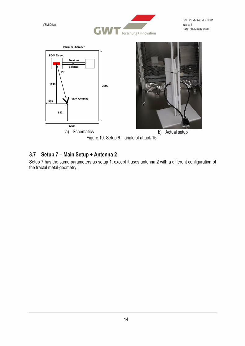
3.6 Setup 6 – Angle 15°
Setup 6 (Figure 10) has the antenna pointing towards the target at an angle of 15° and also has the steel grid with tin foil placed between the antenna and the balance. The distance to the side of the chamber increased to 555 mm. The distance to the back did not change.
y
Vacuum Chamber
795
329
VEM Antenna
Balance
2500
POM Target
607
Torsion-
1200
VEM Drive
Doc: VEM-GWT-TN-1001
Issue: 1
Date: 5th March 2020
14
a) Schematics
b) Actual setup
Figure 10: Setup 6 – angle of attack 15°
3.7 Setup 7 – Main Setup + Antenna 2
Setup 7 has the same parameters as setup 1, except it uses antenna 2 with a different configuration of the fractal metal-geometry.
y
Vacuum Chamber
882
555VEM Antenna
Balance
2500
POM Target
1130
Torsion-
15°
1200

VEM Drive
Doc: VEM-GWT-TN-1001
Issue: 1
Date: 5th March 2020
15
4 RESULTS This section will present the results of the test campaign. First, it will describe the calibration of the balance and then the results for each setup.
4.1 Balance Calibration
The balance was calibrated after the antenna was in place and all RF tests, described in section 2.1.3, were finished. Figure 11 shows the result of the calibration that gives a conversion factor between displacement and force of K = 1.86 µN/µm.
Figure 11: Balance calibration after evacuation of chamber with K = 1.86 µN/µm
For setups that did not change the position of the balance, only a very quick check of the calibration factor was done. A force was commanded and compared to the measured force. When both were the same, no complete calibration was performed again. However, after changes to the balance or the environment (evacuating the chamber) a complete calibration was performed. The factor at the beginning of the campaign was 2.10 µN/µm, which changed during the vacuum test to 1.86 µN/µm. All measurements presented here were performed after the vacuum test, so the force was calculated using K = 1.86 µN/µm.

VEM Drive
Doc: VEM-GWT-TN-1001
Issue: 1
Date: 5th March 2020
16
4.2 Force Measurements
Each setup was tested at different power levels. A representative force measurement is shown in Figure 12 for setup 1 (distance antenna-balance of 1130 mm and on air). A power pulse to the VEM antenna caused a corresponding movement of the balance that is converted into thrust. For the force measurement, the average of the second half of the power pulse is used after the balance movement settled. A table next to the graph lists the force and reflected power at the circulator for each commanded power to the antenna. Because the circulator power is very low, the antenna was working well at its resonance. The measured force of the balance increased with higher power levels. The positive force means that the POM target moves away from the antenna. Although the force was rather small (in the µN range compared to expected fractions of a Newton), the fact that we do measure something was surprising.
Figure 12: Results setup 1 – 20 W
Com. Power [W]
Force [µN]
Circ. Power [W]
5 7.2 0.0
10 14.0 0.1
15 24.0 0.1
20 25.0 0.1
25 30.0 0.1
30 40.0 0.1
35 41.0 0.1
40 49.0 0.1
45 50.0 0.1
Table 2: Results setup 1 (main) Figure 13 shows a comparison of this setup against different distances and angles. All measurements are quite similar within a certain spread – with the exception of the antenna position at 90°. However, later analysis revealed that this was not due to the position but due to a setting on our computer program, which forced the voice-coil actuator to remain at zero current (see next section).
Next, Figure 14 shows a comparison of the force values for different power level in different environments, including high vacuum, a metal grid or thermal shield between antenna and balance as well as the second antenna. The surprise here was that the metal grid, which should shield electromagnetic radiation between antenna and balance, actually nearly doubled the measured force. The radiated power of the antenna outside the chamber was measured using the spectrum analyzer and it was 10 dB lower compared to the measurements without the shield. The thermal shield resulted again in a zero-measurement, again due to a different voice-coil setting on the computer program. We therefore concluded that the observed force is most likely a facility artefact and not due to an electromagnetic (rules out with metal grid shield) or thermal interaction (ruled out with vacuum).

VEM Drive
Doc: VEM-GWT-TN-1001
Issue: 1
Date: 5th March 2020
17
Figure 13: Comparison of Different Distances and Angles – All Measurements in Air
Figure 14: Comparison of Different Measurement Conditions with same Distance

VEM Drive
Doc: VEM-GWT-TN-1001
Issue: 1
Date: 5th March 2020
18
4.3 Voice Coil Influence Measurements
As already mentioned in the section before, the voice coil (the calibration device of the balance) seems to have an influence on the measurements. Usually it does not matter if the power supply is on or off – because a command of zero-current is equivalent of a zero-force on our calibrator. However, the DC power supply has most likely a diode in its internal circuit and therefore can rectify an AC signal that is picked up by the coil. This can easily be tested by e.g. changing the polarity of the voice coil connections which should then also reverse the observed force. This lead to the following tests:
- A) Setup 1 + cable of voice coil normal (positive) - B) Setup 1 + cable of voice coil flipped (negative) - C) Setup 1 + cable of voice coil disconnected and “open circuit” - D) Setup 1 + cable of voice coil disconnected and “shortened circuit”
Figure 15: Comparison of voice coil results (fits do not
include force of 40 W)
Test Force [µN]
Circ. Power [W]
A 42.0 0.1
B -42.0 0.1
C 2.9 0.1
D -1.7 0.1
Table 3: Voice coil results for 30 W commanded power
Figure 15 and Table 3 show the results of these tests. It can be clearly seen that the direction of the force indeed changed, by reversing the connection of the voice coil. In addition, if the power supply is disconnected, the force vanishes as well (no diode to rectify a signal in the loop any more). Figure 16 shows a measurement of the induced voltage in the voice coil for 1.0 W commanded power to the antenna. The voice coil picks up the commanded frequency of 146.0 MHz with a voltage amplitude of 0.3 V. This voice coil test showed, that all previous measurements (setup 1 to 7) were all artifacts caused by the voice coil.
Figure 16: Oscilloscope measurement of voice coil for 1 W commanded power

VEM Drive
Doc: VEM-GWT-TN-1001
Issue: 1
Date: 5th March 2020
19
4.4 Additional Remarks
After antenna 1 was removed from the chamber, burn marks were spotted on the copper parts of the antenna. These spots are located at the top and bottom parts and were most likely caused during the higher power levels. Antenna 2 showed no such marks, but was also used less than antenna 1.
a) Top part
b) Bottom part
Figure 17: Burn marks on antenna 1 Burn marks were also spotted at the bottom of the vacuum chamber, around the base the antenna mount (Figure 18). They are pointing towards the balance.
Figure 18: Burn marks around the antenna
VEM Drive
Doc: VEM-GWT-TN-1001
Issue: 1
Date: 5th March 2020
20
5 CONCLUSION A VEMDrive at a resonance frequency of 146 MHz within the VHF band was tested with power levels up to 45 W inside a large vacuum chamber that allowed sufficient space for testing inside and blocked the radiation to the outside environment. A µN-resolution thrust balance with a POM target mass was used to determine if a force from a claimed spacetime-distorsion can be measured. The balance used a laser interferometer to determine the force and a voice-coil actuator for calibration purposes. Initially, forces in the range of 1 µN/W were seen, which is orders of magnitude below claimed values [1]. No particular influence on distance and orientation as well as different environments (vacuum, air or shields) were found. However, some measurements showed zero forces if the calibrator’s power supply was turned on although at zero command. This led us to suspect that the coil of the calibrator picks up the high frequency radiation. If the power supply is turned on, internal diodes rectify this AC signal into a DC output which in turn caused the balance to move. By changing the polarity of the coil and by disconnecting it from the power supply, the observed force was able to flip polarity too and eventually vanish. We therefore conclude that the VEMDrive does not produce any anomalous forces at its resonance frequency of 146 MHz and within our tested power levels and balance resolution. Our measurements set a limit of 0.050 µN/W for any anomalous forces (compared to claimed 3780 µN/W [1]) – some 6 orders of magnitude below. This is just an order of magnitude higher than standard radiation pressure and therefore even if a force exists in that range, it would not be better than current state-of-the-art. In any case, the influence of a voice-coil calibration in combination with a RF environment is certainly of interest and should be taken into account for similar measurements. A simple relay, which disconnects the calibrator during measurements, is advisable to eliminate this problem.

VEM Drive
Doc: VEM-GWT-TN-1001
Issue: 1
Date: 5th March 2020
21
6 REFERENCES [1] D. P. Pares and K. Finley, “The artificial inducement of a local space warp bubble using a VEM
drive,” AIAA Joint Propulsion Conference, AIAA 2018-4633, 2018. [2] M. Kößling, M. Monette, M. Weikert, and M. Tajmar, “The SpaceDrive project - Thrust balance
development and new measurements of the Mach-Effect and EMDrive Thrusters,” Acta Astronaut., vol. 161, no. May, pp. 139–152, 2019.