final report “consolidated research and development for ... · surface vessels in shallow waters...
TRANSCRIPT

Final Report 1 July 2007 DTPH56-05-T-0004 #161
Final Report
“Consolidated Research and Development for Pipeline Safety” Use of Unmanned Underwater Vehicle (UUAV) for Pipeline Surveillance to Improve Safety and Lower Cost
Contract Number: DTPH56-05-T-0004 Prepared for: United States Department of Transportation Pipeline and Hazardous Materials Safety Administration Office of Pipeline Safety Prepared by: Mr. Ian Wood Team Project Manager Electricore, Inc. 27943 Smyth Drive, Suite 105 Valencia, CA 91355 [email protected]
Final Report 1 July 2007 DTPH56-05-T-0004 #161
Page 2 of 44
Executive Summary The Consolidated Research and Development for Pipeline Safety program was initiated to investigate the feasibility of using remotely piloted underwater vehicles (UUV) with appropriate sensors to:
• detect leaks from transmission pipelines, • locate right of way encroachments, • video record encroachment violations with damage, and • reduce the cost of pipeline surveillance.
The project, conducted over 2005 and 2006, explored the possibility of achieving enhanced monitoring of sub-sea pipelines through the use of commercially available sensors that can be deployed on a UUV. UUVs are not commercially competitive to divers and sensors mounted to surface vessels in shallow waters of less than 100m. Sub-sea pipelines in water depths greater than 100m are laid directly on the seafloor and are not buried. Consequently the focus of this study was on the monitoring of unburied sub-sea pipelines. Currently, there is very little commercial or regulatory requirement at present for sub-sea pipeline surveillance at these depths except during installation of the pipe or following possible encroachment incidents such as anchor dragging near, or over, pipeline routes. These types of surveillance tasks require a capability to detect objects such as anchors and chain dropped near the pipeline, bottom disturbances from anchor drags near or across a pipeline, and misalignment or damage to unburied pipelines. This project investigated commercially available sub-sea sensors that may provide a safer and more efficient means to quickly survey a deep water pipeline to identify possible encroachment, external damage or misalignment, and leak locations. Based on the results of the project, preliminary specifications have been developed for the following system components:
• Unmanned Vehicle requirements • Sensor payload requirements
Additionally, preliminary operational concepts were developed for the application of UUV technology to pipeline monitoring and surveillance for a variety of mission profiles. While much work was completed on this mission, completion was not possible due to forces beyond the control of the participants. In August and September of 2005 Hurricanes Katrina and Rita struck the Gulf Coast of the United States. The current offshore resources schedule is focused around priority commercial inspection and repair activities in the wake of damage from Hurricanes Katrina and Rita. The offshore resources needed to complete the Consolidated Research and Development for Pipeline Safety project have not been and will not be available for the foreseeable future.

Final Report 1 July 2007 DTPH56-05-T-0004 #161
Page 3 of 44
1 Table of Contents 1 Table of Contents..................................................................................................................3 2 Overview ...............................................................................................................................4 3 Mission Requirements...........................................................................................................4
3.1 Encroachment Detection ...............................................................................................5 3.2 Leak Detection ..............................................................................................................5
4 Vehicle Requirements ...........................................................................................................6 4.1 Currently Available ROV Systems.................................................................................6 4.2 MAXXIMUM...................................................................................................................7 4.3 MILLENNIUM ................................................................................................................7 4.4 MAGNUM......................................................................................................................8
5 Payload Requirements and Evaluation .................................................................................9 5.1 UUV Payload Technology Evaluation ...........................................................................9 5.2 Payload Selection........................................................................................................13 5.3 Sensor Integration into UUV........................................................................................14
6 Operational Scenarios Employing an AUV .........................................................................14 7 Test Plan .............................................................................................................................15
7.1 Scope ..........................................................................................................................16 7.2 Evaluation Matrix.........................................................................................................17 7.3 Pre-Testing..................................................................................................................18
8 Conclusion ..........................................................................................................................18 9 Appendix A..........................................................................................................................19
9.1 U.S. Department of Transportation, Office of Pipeline Safety Regulations .................19 9.2 U.S. Department of Interior, Mineral Management Service Regulations.....................21 9.3 Applicable State Regulations ......................................................................................23 9.4 Current Industry Practice.............................................................................................23 9.5 Industry Standards ......................................................................................................23
10 Appendix B......................................................................................................................25 10.1 MAXXIMUM ROV SYSTEM SPECIFICATIONS .........................................................25 10.2 MILLENIUM ROV SYSTEM SPECIFICATIONS .........................................................26 10.3 MAGNUM ROV SYSTEM SPECIFICATIONS: ...........................................................28
11 Appendix C......................................................................................................................30 11.1 Detailed Test Plans .....................................................................................................30 11.2 A Primer for Oceaneering Work Vessels and ROV Systems ......................................30 11.3 Vessel & ROV System Prep. for At-sea Pipeline Inspection Sensor Evaluation.........33 11.4 Leak Detection ............................................................................................................36 11.5 Pipeline & Surrounding Environment “Visualization”...................................................40 11.6 Control and Reporting Procedures..............................................................................42 11.7 Pre-Test.......................................................................................................................42 11.8 Test Conduct ...............................................................................................................42 11.9 Post Test .....................................................................................................................42
12 Glossary ..........................................................................................................................44

Final Report 1 July 2007 DTPH56-05-T-0004 #161
Page 4 of 44
2 Overview The Consolidated Research and Development for Pipeline Safety program was initiated to investigate the feasibility of using remotely piloted underwater vehicles (UUV) with appropriate sensors to detect leaks from transmission pipelines, locate right of way encroachments, video record encroachment violations with damage, and reduce the cost of pipeline surveillance. The project explored the possibility of achieving enhanced monitoring of sub-sea pipelines through the use of commercially available sensors that can be deployed on a UUV. UUVs are not commercially competitive to divers and sensors mounted to surface vessels in shallow waters of less than 100m. Sub-sea pipelines in water depths greater than 100m are laid directly on the seafloor and are not buried. Consequently the focus of this study was on the monitoring of unburied sub-sea pipelines. Currently, there is very little commercial or regulatory requirement at present for sub-sea pipeline surveillance at these depths except during installation of the pipe or following possible encroachment incidents such as anchor dragging near, or over, pipeline routes. These types of surveillance tasks require a capability to detect objects such as anchors and chain dropped near the pipeline, bottom disturbances from anchor drags near or across a pipeline, and misalignment or damage to unburied pipelines. This project investigated commercially available sub-sea sensors that may provide a safer and more efficient means to quickly survey a deep water pipeline to identify possible encroachment, external damage or misalignment, and leak locations. While much work was completed on this mission, completion was not possible due to forces beyond the control of the participants. In August and September of 2005 Hurricanes Katrina and Rita struck the Gulf Coast of the United States. The current offshore resources schedule is focused around priority commercial inspection and repair activities in the wake of damage from Hurricanes Katrina and Rita. The offshore resources needed to complete the Consolidated Research and Development for Pipeline Safety project have not been and will not be available for the foreseeable future. Many milestones for this project have been completed. These milestones include the development of Mission Requirements, UUV Payload Technology Evaluation and Test Plan. A summary of the completed work follows in this document.
3 Mission Requirements Because current regulations (see Appendix A) do not require regular sub-sea monitoring of sub-sea pipelines, UUVs are not used to monitor pipelines except as a reaction to potential damage. Industry interest is thus in sensors that can locate and define encroachment, damage, and leaks in a faster and less costly manner. Each of these technologies requires accurate positioning of the sub-sea targets relative to surface GPS positions. Specific missions that pipeline operators are interested in that are applicable to a UUV application include:
• Detecting anchors, debris , or seafloor drag marks that are close to pipelines • Detecting pipeline misalignment from the original as-built position • Identifying pipeline suspensions above the seafloor • Confirming new sub-sea pipelines, cables, wellheads, or other seafloor equipment have
not encroached on a safe separation from existing pipelines

Final Report 1 July 2007 DTPH56-05-T-0004 #161
Page 5 of 44
• Identifying small pipeline leaks that are difficult to detect and locate by current methods • Providing accurate, high resolution images of damage to the pipeline
3.1 Encroachment Detection The first mission scenario is to detect pipeline right of way encroachments, accurately map their location and provide a real time visual image of the problem area. In deepwater, the most serious encroachment problem is from the anchors for a drill rig or construction vessel being dragged across a pipeline during tropical storms. A typical platform mooring leg consists of a 20,000lb anchor connected to 3000 ft of 3 ¼ inch ORQ chain connected to 3 ½ IWRC wire rope. Such a mooring leg is tensioned to approximately 250,000lbs. Great care is taken during installation to survey-in the anchors to a safe position avoiding encroachment. However, if a hurricane comes into the area, rigs have been known to drag anchor as far as 60 miles. Thus, it becomes important to survey any pipelines across the path the rig took to look for the bottom scars of the anchor’s path across the pipelines and check for localized damage to the pipeline or misalignment from its original position. Replotting the actual pipe position can be used to calculate the resulting induced stresses to determine if the displacement has caused the allowable stresses to be exceeded. The sensor suite that can provide accurate identification and mapping for anchor drag encroachment, should also provide a means of identifying the position of other sub-sea equipment or debris which may encroach on a safe distance from an existing pipeline. Finally, the same sensor suite should also be able to identify pipeline suspensions. Suspensions could develop as a result of the pipe being moved, or the seafloor slumping due to seismic activity, slope instability, or gas pockets. Once again, the unsupported span of pipe will have higher induced stresses and is also subjected to potential strumming fatigue in high current areas. 3.2 Leak Detection
The second mission scenario is to determine the system’s reliability and accuracy in locating leaks associated with underwater pipelines, map their position on a GPS map and provide a real time and high resolution image of the problem area. Data collected may be incorporated into a geographic information system (GIS). Currently, pipeline operators detect the possibility of sub-sea pipeline leaks by recognizing a drop in pressure or flow volume in the pipe at the ends of the pipe or by spotting visual bubble trails, oil sheens, and/or slicks from helicopters or surface vessels transiting the area.
Present technology to home in on a specific location for an underwater leak with a UUV is very short range. If the leak is large enough it can be followed visually to the source. Smaller leaks have been detected by injecting a tracer such as fluoroscein into the pipeline and using tuned light sources and detectors to identify the presence and concentration of the flourescein. Such approaches are limited to 5-7 m range and so are difficult to employ for rapid localization of the leak. Sub-sea leak detection will be a significant challenge as most of the sensors developed for use in air will not work underwater. A comprehensive study of available sensor technologies to help in this mission will be conducted in the Payload Evaluation portion of this project.

Final Report 1 July 2007 DTPH56-05-T-0004 #161
Page 6 of 44
4 Vehicle Requirements
The proposed UUV is a commercial design consisting of a remotely operated vehicle (ROV) operated from a surface vessel. The ROV approach allows a real-time transmission of high bandwidth data such as that provided by video and sonar. This is possible due to the fiber optic elements in the ROV umbilical to the surface ship. Autonomous underwater vehicles can only transmit data acoustically which is at very low baud (900 is typical) rates.
The ROV selected will be one that has sufficient extra ports and telemetry capacity available to add the demonstration sensors. Oceaneering has reviewed this with our ROV operations group and found three classes of work-class ROVs, which are deemed suitable for these trials:
The final selection of vehicle will depend on several factors, including:
1. The vessels (and their respective ROVs) that are available during the test period and that also have berthing space available
2. Of those meeting criteria (1), the vessels will be at the most advantageous test
location(s) during the test time period
3. Of those meeting criteria (1) and (2), select the vessels that have the best UUV interfaces to the demonstration payload to ensure success. Factors include:
• Workload • Spare channels • Spare power provision
Part of the consideration for ROV selection centers on the amount of extra power, power connection taps, and telemetry bandwidth available on that specific ROV. Each ROV is configured differently for each vessel, customer, and/or project. The equipment for the project testing must coexist with whatever equipment is already being used on that ROV. That could drive ROV selection. Further development may be required in the desired demonstration payload interfaces and some flexibility to fit into the best possible opportunity to demonstrate it in conjunction with ongoing work.
4.1 Currently Available ROV Systems
There are three general classes of Oceaneering work-class ROV systems that provide the best capability for the pipeline monitoring demonstration payload. These three ROV classes are the “Maxximum”, “Millennium”, and “Magnum” systems.
Oceaneering has two “Maxximum” systems which are the newest and most capable systems. These systems reside exclusively on Oceaneering’s Intervention – 1 and –2 vessels, the largest and most capable ocean construction support vessels in Oceaneering’s fleet.
The Millennium class vehicles are a very heavy-duty vehicle used on many platforms and a few vessels. While not as numerous as the Magnum class of ROV, this vehicle could be easily used for the demonstration testing.

Final Report 1 July 2007 DTPH56-05-T-0004 #161
Page 7 of 44
The Magnum class represents the standard of Oceaneering’s ROVs and is the most numerous of those in the fleet. It is a very capable work vehicle, with power ranging from 75hp to 100hp. A Magnum’s system’s capabilities far exceed the requirements imposed by the nominal sensor suite.
The sections below present the design specifications for the three vehicle types:
4.2 MAXXIMUM The Hydra® MAXXIMUM is a cage deployed, dual manipulator 300 HP work class ROV system. Enhanced thruster configuration provides center lift capacity of nearly 3,000 lbs and forward pivoted bollard lift capacity in excess of 1,800 lbs. The system employs a microprocessor-based telemetry system to minimize maintenance, decrease set up time, simplify troubleshooting, and provide more automated control functions. Tooling control is accomplished external to main telemetry in order to maintain both flight control and tooling control at maximum flexibility and efficiency.
Figure 1 – Hydra® MAXXIMUM Unmanned Underwater Vehicle A direct fiber optic link between console and vehicle is the primary transmission path for all video and data signals. The link provides the finest quality video available in deepwater ROV technology as well as tremendous bandwidth for sensors and equipment. The MAXXIMUM design evolved in response to extensive discussions with Customers who were looking for enhanced performance and work capabilities to support their deepwater drilling and field development programs worldwide. See Appendix B for full specifications on the MAXXIMUM ROV. 4.3 MILLENNIUM Hydra® MILLENNIUM ROVs are150-hp high performance work class vehicles developed specifically to operate in water depths greater than 10,000 feet and for shallower deepwater applications that may require specialized work capability. This includes the ability to run and operate tools, such as large dredge and jet pumps, which require very high hydraulic fluid flow volumes.

Final Report 1 July 2007 DTPH56-05-T-0004 #161
Page 8 of 44
Figure 2 – Hydra® MILLENIUM Unmanned Underwater Vehicle With a strong emphasis on reliability and standardization, the MILLENNIUM is based on the proven Hydra® MAGNUM series design with higher horsepower, deeper water depth capability, and a larger payload. It utilizes the newly developed MAGNUM cage design which allows vehicles of either series to carry and operate work packages of any shape and size suitable for ROV deployment. The MILLENNIUM design was developed in response to extensive discussions with operators who are looking for enhanced performance and work capabilities to support their deepwater drilling and field development programs in the Gulf of Mexico, Brazil, West of Shetlands, and Norway. See Appendix B for full specifications on the MILLENIUM ROV. 4.4 MAGNUM Hydra® MAGNUM ROVs are high-thrust, cage-deployed vehicles designed to accommodate a variety of sensor and work packages for performing a wide range of underwater intervention tasks that support oil and gas drilling, construction, and production activities.
Figure 3 – Hydra® MAGNUM Unmanned Underwater Vehicle

Final Report 1 July 2007 DTPH56-05-T-0004 #161
Page 9 of 44
These vehicles are 100-horsepower units capable of operating down to 10,000 feet of seawater (fsw) and are being manufactured using the latest technology in advanced control systems for high performance, optimum adaptability, and maximum reliability. See Appendix B for full specifications on the MAGNUM ROV.
5 Payload Requirements and Evaluation
The UUV systems are capable of carrying a range of commercially available payloads including black and white or color still digital imaging cameras and low light level video cameras and a host of environmental sensors. In addition, scanning digital sonar is a potential technology for high resolution acoustic imaging with greater range than that possible with optical sensors. Positioning of the sensors can be done by inertial systems and acoustic positioning tied to a Global Positioning System (GPS) on the surface support platform. Concurrent data acquisition and processing displays in near real-time is desired feature for the selected sensors.
Table 1 – Payloads SIT video Digital still camera Digital Scanning Sonar USBL positioning IMU GPS (surface vessel) Compass heading Other Environmental Sensors (TBD)
5.1 UUV Payload Technology Evaluation The Oceaneering project team has conducted preliminary assessments commercially available payload technology to determine the options available achieve the mission requirements. Sensors, digital imagery, and data processing options were reviewed. All options were screened for the feasibility of use on the chosen demonstration platform, Oceaneering’s Magnum, Millenium, and Maxximum class ROVs. These platforms were described in some detail in the previous section. In addition, this report investigates sensors now available, but which are not yet suitable for integration into an ROV to meet mission requirements without further technical development. Finally, the project team considered the current payload capabilities of Autonomous Underwater Vehicles (AUV) in order to assess the longer-term developments needed to employ AUVs for pipeline monitoring. Numerous pipeline inspection technologies were identified which could be integrated into an UUV. Some payloads measure a single parameter and others can do a broader range of measurements. Some are ill suited to typical UUV operations or even ill suited for subsea use altogether. Oceaneering has hands-on familiarity with all these technologies and has used that experience to down-select the candidates that show the most promise for the desired tasks.

Final Report 1 July 2007 DTPH56-05-T-0004 #161
Page 10 of 44
Table 2 below presents each of the common pipe inspection techniques/technologies and evaluates which of the posed questions it can reasonably, reliably, and feasibly answer when used as part of an UUV system that also includes all other supporting subsystems needed (eg. A camera can tell where a pipe is only to the degree that the UUV’s navigational subsystem can pinpoint its location precisely when the image is taken).

Final Report 1 July 2007 DTPH56-05-T-0004 #161
Page 11 of 44
Table 2 – Functional Comparison of Commercially Available Inspection Sensors
TECHNOLOGY HOW IT WORKS
SUT
AB
LE
FO
R
SUB
SEA
USE
?
RE
AD
ILY
IN
CO
RPO
RA
TE
D IN
TO
U
UV
?
IN P
RO
PER
L
OC
AT
ION
?
DE
BU
RIE
D ?
OR
SU
SPE
ND
ED
?
DA
MA
GE
D?
LE
AK
ING
?
EN
CR
OA
CH
ME
NT
?
SCA
RR
ING
?
Caliper Physically measures diameter and circularity of pipe. Hydrogen Flame
Leak Detector Detects ionized constituents of leaking hydrocarbons.
Visual Camera UUV flies route taking photos. Post processing with metadata provides mosaic of pipeline condition. C C C C C
Infrared Camera Post processed infrared data detects leakage plumes and thermal differences on/near pipe due to leakage. T T T
Acoustic Camera Views a thin, wedge shaped slice of water (2D) C C C C
Acoustic Emissions
Uses an acoustic sensor pressed against pipe listening for response after pipe is struck with a hammer of known force. May hear leakage if sufficiently close to a sufficiently large leak.
C C
Active Radological Source
Uses an active radiological source to “shoot” through a pipe. A sensor on the opposite side of the source records the shot. Can see defects in pipe wall and sometimes flooded members.
T T C
Digital Multi-beam A form of sonar. Capable of producing 3D images with full metadata C C
Laser Line Scanner (LLS)
There are several types of LLS in common use. All incorporate three basic components: A (pulsed) laser, a scanning device (such as a spinning mirror), and an optical receiver. Depending on the system configuration, trading one performance consideration for another, the systems are affected by pressure, object reflectivity, and even color. Primary detractors from this type of sensor are cost ($700k) and size (~5’ long without beam folding).
T C

Final Report 1 July 2007 DTPH56-05-T-0004 #161
Page 12 of 44
TECHNOLOGY HOW IT WORKS
SUT
AB
LE
FO
R
SUB
SEA
USE
?
RE
AD
ILY
IN
CO
RPO
RA
TE
D IN
TO
U
UV
?
IN P
RO
PER
L
OC
AT
ION
?
DE
BU
RIE
D ?
OR
SU
SPE
ND
ED
?
DA
MA
GE
D?
LE
AK
ING
?
EN
CR
OA
CH
ME
NT
?
SCA
RR
ING
?
Fluorescence w/ Optical Camera
A fluorescent dye is injected into the product stream, which can be detected by a camera. Sufficient leakage is required for optical detection. Delectability is enhanced by camera performance in ultraviolet range.
Fluorescence w/ LLS
Hydrocarbons fluoresce, which allows sensitive instrumentation to see small amounts of hydrocarbons in water. These sensors combine the functionality of LLS with the ability to detect a leak.
T
Chemical “Sniffer”
Sensor consists of a semiconductor that undergoes changing conductance with presence of methane on its surface. The methane arrives on the sensor through a semi-permeable membrane driven by the partial pressures of methane on either side of it.
“YES” Sensor with properly configured UUV is robustly capable of executing task
“PERHAPS”
“?C” - Sensor with properly configured UUV is capable of executing task in ideal conditions (eg: being able to see a displaced pipe if the bottom conditions are not murky). -OR- “?T” - Sensor technology should be able to perform task but is not mature enough, or supporting data has not been discovered, which would substantiate its being robustly capable to perform.
“NO” Sensor is not suited to perform task. = NOT CONSIDERED FURTHER IN STUDY = CONSIDERED IN STUDY

Final Report 1 July 2007 DTPH56-05-T-0004 #161
Page 13 of 44
5.2 Payload Selection Several specific examples of each type of sensor technology listed in Table 2 are available on the commercial market. Oceaneering evaluated the field of candidates and selected those shown in Table 3 below as representing the best of what is readily available today. Of these, the ones that were targeted for at-sea evaluation are highlighted in green background.

Final Report 1 July 2007 DTPH56-05-T-0004 #161
Page 14 of 44
5.3 Sensor Integration into UUV The key difference between the two types of UUVs, ROVs and AUVs is the power available to the subsea payload and the bandwidth of available communication between the vehicle and the operator. ROVs can be controlled “real time” by an operator and have a constant and direct supply of power available through an umbilical cable to the surface support vessel. AUVs have no umbilical cable and so are limited in the supply of power and in the amount of control and communication with the surface. Communication with an AUV is by acoustic modem and communication data rates through water are a mere fraction of that necessary to provide meaningful situational awareness, vehicle control input, or video. So once an AUV is launched, the operators on the surface have very limited ability to monitor and redirect the preprogrammed mission. For these reasons, this project planned to employ an ROV for demonstrating the selected sensors. However, the results of the demonstrations were to be evaluated for the efficacy of the sensors for subsequent development as AUV- supported payloads which are discussed in the subsequent paragraphs. The previous table of currently available sensors can be distilled into two classes of commercially available products. The first class chemically “sniffs” the water to detect the presence hydrocarbons and some other chemicals. The second class “images” the environment. Imaging may be as simple as storing a 2D “picture,” or as complex as processing that image, analyzing the processed image combined with a database of known objects and features so that it can recognize a unburied pipe, suspensions, encroachments, and changes from the previous as-laid positions. One of the key questions at this point is, “How usefully can any sensor be integrated into a UUV to provide ‘real-time information’ to augment the vehicle’s decision-making?” Although some of these sensors have been assembled into a few AUV vehicles, the tangible bump in technology is the genuine integration of these sensors into an AUV pipeline inspection System. A nominal vehicle configuration would combine at least one “sniffer” with one “imager” sensor, with more than one imager being highly desirable, but perhaps not feasible for size, power, and weight limitations. That fully integrated solution can ultimately come only after a complete comprehension of the “real world” capabilities of the sensors contemplated: Far over and above what can be gleaned from the available sales literature. This study and subsequent field-testing attempt to attain that comprehension. The scenarios that follow assume that the sensors contemplated live up to the initial assessment. As stated before, we have “hands-on” knowledge of most of them, but what we don’t know is how thoroughly they will integrate into, and augment the functionality of an AUV. Another way of stating this is that the technology by itself is mature; the comprehensive melding of that technology with a vehicle is not quite so mature.
6 Operational Scenarios Employing an AUV Several foreseeable operational missions for AUVs working with an ROV or alone are possible. The chief advantage of an AUV is its lack of surface support vessel required and the speed at which it can cover larger areas. To establish a “feasible mission scenario” requires a definition of how intelligent the AUV will be. The simplest type of mission would be to install sensors into
Final Report 1 July 2007 DTPH56-05-T-0004 #161
Page 15 of 44
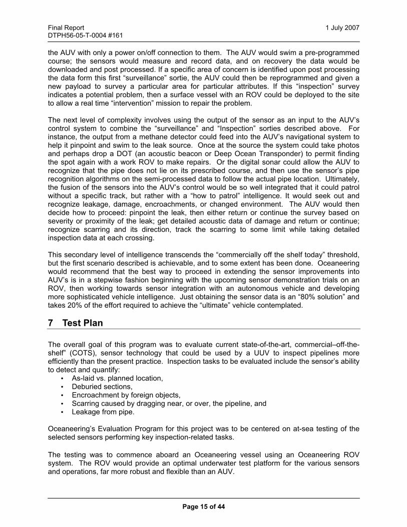
the AUV with only a power on/off connection to them. The AUV would swim a pre-programmed course; the sensors would measure and record data, and on recovery the data would be downloaded and post processed. If a specific area of concern is identified upon post processing the data form this first “surveillance” sortie, the AUV could then be reprogrammed and given a new payload to survey a particular area for particular attributes. If this “inspection” survey indicates a potential problem, then a surface vessel with an ROV could be deployed to the site to allow a real time “intervention” mission to repair the problem. The next level of complexity involves using the output of the sensor as an input to the AUV’s control system to combine the “surveillance” and “Inspection” sorties described above. For instance, the output from a methane detector could feed into the AUV’s navigational system to help it pinpoint and swim to the leak source. Once at the source the system could take photos and perhaps drop a DOT (an acoustic beacon or Deep Ocean Transponder) to permit finding the spot again with a work ROV to make repairs. Or the digital sonar could allow the AUV to recognize that the pipe does not lie on its prescribed course, and then use the sensor’s pipe recognition algorithms on the semi-processed data to follow the actual pipe location. Ultimately, the fusion of the sensors into the AUV’s control would be so well integrated that it could patrol without a specific track, but rather with a “how to patrol” intelligence. It would seek out and recognize leakage, damage, encroachments, or changed environment. The AUV would then decide how to proceed: pinpoint the leak, then either return or continue the survey based on severity or proximity of the leak; get detailed acoustic data of damage and return or continue; recognize scarring and its direction, track the scarring to some limit while taking detailed inspection data at each crossing. This secondary level of intelligence transcends the “commercially off the shelf today” threshold, but the first scenario described is achievable, and to some extent has been done. Oceaneering would recommend that the best way to proceed in extending the sensor improvements into AUV’s is in a stepwise fashion beginning with the upcoming sensor demonstration trials on an ROV, then working towards sensor integration with an autonomous vehicle and developing more sophisticated vehicle intelligence. Just obtaining the sensor data is an “80% solution” and takes 20% of the effort required to achieve the “ultimate” vehicle contemplated.
7 Test Plan The overall goal of this program was to evaluate current state-of-the-art, commercial–off-the- shelf” (COTS), sensor technology that could be used by a UUV to inspect pipelines more efficiently than the present practice. Inspection tasks to be evaluated include the sensor’s ability to detect and quantify:
• As-laid vs. planned location, • Deburied sections, • Encroachment by foreign objects, • Scarring caused by dragging near, or over, the pipeline, and • Leakage from pipe.
Oceaneering’s Evaluation Program for this project was to be centered on at-sea testing of the selected sensors performing key inspection-related tasks. The testing was to commence aboard an Oceaneering vessel using an Oceaneering ROV system. The ROV would provide an optimal underwater test platform for the various sensors and operations, far more robust and flexible than an AUV.

Final Report 1 July 2007 DTPH56-05-T-0004 #161
Page 16 of 44
This section will present details from Oceaneering’s plan to perform the various sensor evaluations of this project in an organized logical fashion. The detailed test plans provide:
a. A comprehensive explanation of what would have transpired during that test, and what preparations would be necessary.
b. A well considered basis on which to generate Test Procedures. c. Identify customers with the ability to draw expectations for the tests.
7.1 Scope The scope of the testing was to evaluate the performance, suitability and feasibility of several sensors to perform various pipeline inspection tasks. Follow-on analysis would evaluate how readily the COTS sensor could be used for its intended purpose or what level of customization would be required (but still “COTS”: In the ROV industry it is common to order sensors with some minor customizations: Data frame information for those with serial port connectivity, specific cable lengths and connector brands/sizes, various analog output formats, and power supply voltages). All of the requirements and goals, along with the method prescribed to verify those requirements for a product / project, are presented in an Evaluation Matrix, found in the next sub-section.
Figure 4 – Evaluation Plan for Pipeline Inspection Sensors

Final Report 1 July 2007 DTPH56-05-T-0004 #161
Page 17 of 44
7.2 Evaluation Matrix
PIPELINE MONITORING SENSOR TEST REQUIREMENT MATRIX VERIFICATION
METHOD
REQMT NO. REQUIREMENT TEXT T/D A NOTES Tes
t Pro
cedu
re
Doc
. No.
Tes
t Rep
ort D
oc.
No.
SYSTEM LEVEL REQUIREMENTS S1 Unburied Pipe X . S2 Water depth >100m and <10,000ft X . S3 Current = 0 - 2 kt X . S4 (DEFINE VISIBILITY GOAL) X . S5 Functional with the available power X . S6 Functional with the available data bandwidth X . S7 Fit within available size envelope on ROV or Cage X . S8 Fit within available weight envelope of ROV or Cage X . S9 . . S10 . . S11 . . S12 . . FUNCTIONAL REQUIREMENTS F1 Ability to "see" a pipe X . F2 Ability to "track" a pipe X . F3 Ability to resolve damage to a pipe's outer surface (dimple, hole) X . F4 Ability to see soil scarring around pipe X . F5 Ability to detect "small" natural gas leakage (TBD SCFD) X . F6 Ability to detect "large" natural gas leakage (TBD SCFD) X . F7 Ability to detect "small" liquid petroleum leakage (TBD GPD) X . F8 Ability to detect "large" liquid petroleum leakage (TBD GPD) X . F9 Ability to Detect at far (TBD distance) from pipe X . F10 Ability to see other debris (TBD size) near pipe or right of way X . F11 Ability to identify pipeline suspensions above the seafloor X . F12 Ability to use existing output to integrate with GIS data . X F13 . . F14 . . (OTHER) . . . . . . . .

Final Report 1 July 2007 DTPH56-05-T-0004 #161
Page 18 of 44
7.3 Pre-Testing Although this plan details the actual testing to be performed at-sea, all systems under consideration were to be thoroughly checked-out during the ROV Integration Phase of the project. The details of those checkout activities would include:
a. Bench testing of received units to ensure they appear functional prior to installing them into the ROV.
b. Operational checkout after integration with the ROV (the scope of this checkout is to
assure that the unit turns on, telemetry between the sensor and topsides performs properly, etc)
c. Some level of Functional Checkout. Depending on the sensor, some checkouts can be
performed prior to mobilizing to make sure the sensor/ROV system is ready to proceed offshore for testing.
A comprehensive Test Plan was been submitted to DOT PHMSA and is included in Appendix C.
8 Conclusion The next phase of the Consolidated Research and Development for Pipeline Safety project cannot currently be completed due to a lack of offshore resources in the wake of Hurricanes Katrina and Rita. Scheduling of the vehicle modifications and at-sea demonstrations has not been possible. For over a year Oceaneering has been scrambling to meet the needs of the offshore industry to restore offshore oil and gas infrastructure devastated by the hurricanes. The demands on Oceaneering’s vessels, ROV systems, divers and personnel were completely unforeseen at the beginning of this project. Because there is no feasible way to support the project’s next task, the project is being terminated.

Final Report 1 July 2007 DTPH56-05-T-0004 #161
Page 19 of 44
9 Appendix A 9.1 U.S. Department of Transportation, Office of Pipeline Safety Regulations 9.1.1 For Natural Gas Transmission Lines CODE OF FEDERAL REGULATIONS TITLE 49--TRANSPORTATION CHAPTER I--RESEARCH AND SPECIAL PROGRAMS ADMINISTRATION, DEPARTMENT OF TRANSPORTATION (CONTINUED) PART 192_TRANSPORTATION OF NATURAL AND OTHER GAS BY PIPELINE: MINIMUM FEDERAL SAFETY STANDARDS Subpart L: Operations Sec. 192.612: Underwater inspection and reburial of pipelines in the Gulf of Mexico and its inlets. (a) Each operator shall prepare and follow a procedure to identify its pipelines in the Gulf of Mexico and its inlets in waters less than 15 feet (4.6 meters) deep as measured from mean low water that are at risk of being an exposed underwater pipeline or a hazard to navigation. The procedures must be in effect August 10, 2005. (b) Each operator shall conduct appropriate periodic underwater inspections of its pipelines in the Gulf of Mexico and its inlets in waters less than 15 feet (4.6 meters) deep as measured from mean low water based on the identified risk. (c) If an operator discovers that its pipeline is an exposed underwater pipeline or poses a hazard to navigation, the operator shall— (1) Promptly, but not later than 24 hours after discovery, notify the National Response Center, telephone: 1-800-424-8802, of the location and, if available, the geographic coordinates of that pipeline. (2) Promptly, but not later than 7 days after discovery, mark the location of the pipeline in accordance with 33 CFR part 64 at the ends of the pipeline segment and at intervals of not over 500 yards (457 meters) long, except that a pipeline segment less than 200 yards (183 meters) long need only be marked at the center; and (3) Within 6 months after discovery, or not later than November 1 of the following year if the 6 month period is later than November 1 of the year of discovery, bury the pipeline so that the top of the pipe is 36 inches (914 millimeters) below the underwater natural bottom (as determined by recognized and generally accepted practices) for normal excavation or 18 inches (457 millimeters) for rock excavation. (i) An operator may employ engineered alternatives to burial that meet or exceed the level of protection provided by burial.

Final Report 1 July 2007 DTPH56-05-T-0004 #161
Page 20 of 44
(ii) If an operator cannot obtain required state or Federal permits in time to comply with this section, it must notify OPS; specify whether the required permit is State or Federal; and, justify the delay. Sec. 192.613: Continuing surveillance. (a) Each operator shall have a procedure for continuing surveillance of its facilities to determine and take appropriate action concerning changes in class location, failures, leakage history, corrosion, substantial changes in cathodic protection requirements, and other unusual operating and maintenance conditions. (b) If a segment of pipeline is determined to be in unsatisfactory condition but no immediate hazard exists, the operator shall initiate a program to recondition or phase out the segment involved, or, if the segment cannot be reconditioned or phased out, reduce the maximum allowable operating pressure in accordance with Sec. 192.619 (a) and (b). NOTE: The 15 ft depth is the OPS requirement MMS takes over if the water is deeper. They have the same needs and might be considered to help in a follow on phase. Hurricane damage from 2004 and 2005 was a big problem with some pipe dragged miles off their normal locations and some had long unsupported spans which can cause buckling. 9.1.2 For Hazardous Liquid Transmission Lines CODE OF FEDERAL REGULATIONS TITLE 49--TRANSPORTATION CHAPTER I--RESEARCH AND SPECIAL PROGRAMS ADMINISTRATION, DEPARTMENT OF TRANSPORTATION PART 195_TRANSPORTATION OF HAZARDOUS LIQUIDS BY PIPELINE Subpart F: Operation and Maintenance Sec. 195.412: Inspection of rights-of-way and crossings under navigable waters. (a) Each operator shall, at intervals not exceeding 3 weeks, but at least 26 times each calendar year, inspect the surface conditions on or adjacent to each pipeline right-of-way. Methods of inspection include walking, driving, flying or other appropriate means of traversing the right-of-way. (b) Except for offshore pipelines, each operator shall, at intervals not exceeding 5 years, inspect each crossing under a navigable waterway to determine the condition of the crossing. Sec. 195.413: Underwater inspection and reburial of pipelines in the Gulf of Mexico and its inlets. (a) Except for gathering lines of 4\1/2\ inches (114mm) nominal outside diameter or smaller, each operator shall prepare and follow a procedure to identify its pipelines in the Gulf of Mexico and its inlets in waters less than 15 feet (4.6 meters) deep as measured from mean low water that are at risk of being an exposed underwater pipeline or a hazard to navigation. The procedures must be in effect August 10, 2005.

Final Report 1 July 2007 DTPH56-05-T-0004 #161
Page 21 of 44
(b) Each operator shall conduct appropriate periodic underwater inspections of its pipelines in the Gulf of Mexico and its inlets in waters less than 15 feet (4.6 meters) deep as measured from mean low water based on the identified risk. (c) If an operator discovers that its pipeline is an exposed underwater pipeline or poses a hazard to navigation, the operator shall— (1) Promptly, but not later than 24 hours after discovery, notify the National Response Center, telephone: 1-800-424-8802, of the location and, if available, the geographic coordinates of that pipeline. (2) Promptly, but not later than 7 days after discovery, mark the location of the pipeline in accordance with 33 CFR Part 64 at the ends of the pipeline segment and at intervals of not over 500 yards (457 meters) long, except that a pipeline segment less than 200 yards (183 meters) long need only be marked at the center; and (3) Within 6 months after discovery, or not later than November 1 of the following year if the 6 month period is later than November 1 of the year of discovery, bury the pipeline so that the top of the pipe is 36 inches (914 millimeters) below the underwater natural bottom (as determined by recognized and generally accepted practices) for normal excavation or 18 inches (457 millimeters) for rock excavation.
(i) An operator may employ engineered alternatives to burial that meet or exceed the level of protection provided by burial.
(ii) If an operator cannot obtain required state or Federal permits in time to comply with this section, it must notify OPS; specify whether the required permit is State or Federal; and, justify the delay.
Sec. 195.444: CPM leak detection. Each computational pipeline monitoring (CPM) leak detection system installed on a hazardous liquid pipeline transporting liquid in single phase (without gas in the liquid) must comply with API 1130 in operating, maintaining, testing, record keeping, and dispatcher training of the system. 9.2 U.S. Department of Interior, Mineral Management Service Regulations MMS 30CFR250 § 250.1002 Design requirements for DOI pipelines. (f) Pipelines shall be designed and maintained to mitigate any reasonably anticipated detrimental effects of water currents, storm or ice scouring, soft bottoms, mud slides, earthquakes, subfreezing temperatures, and other environmental factors. § 250.1003 Installation, testing, and repair requirements for DOI pipelines. (a)(1) Pipelines greater than 8-5/8 inches in diameter and installed in water depths of less than 200 feet shall be buried to a depth of at least 3 feet unless they are located in pipeline congested areas or seismically active areas as determined by the Regional Supervisor. Nevertheless, the Regional Supervisor may require burial of any pipeline if the Regional

Final Report 1 July 2007 DTPH56-05-T-0004 #161
Page 22 of 44
Supervisor determines that such burial will reduce the likelihood of environmental degradation or that the pipeline may constitute a hazard to trawling operations or other uses. A trawl test or diver survey may be required to determine whether or not pipeline burial is necessary or to determine whether a pipeline has been properly buried. (2) Pipeline valves, taps, tie-ins, capped lines, and repaired sections that could be obstructive shall be provided with at least 3 feet of cover unless the Regional Supervisor determines that such items present no hazard to trawling or other operations. A protective device may be used to cover an obstruction in lieu of burial if it is approved by the Regional Supervisor prior to installation. (3) Pipelines shall be installed with a minimum separation of 18 inches at pipeline crossings and from obstructions. (4) Pipeline risers installed after April 1, 1988, shall be protected from physical damage that could result from contact with floating vessels. Riser protection on pipelines installed on or before April 1, 1988, may be required when the Regional Supervisor determines that significant damage potential exists. (b)(1) Pipelines shall be hydrostatically tested with water at a stabilized pressure of at least 1.25 times the MAOP for at least 8 hours when installed, relocated, uprated, or reactivated after being out-of-service for more than 1 year. (2) Prior to returning a pipeline to service after a repair, the pipeline shall be pressure tested with water or processed natural gas at a minimum stabilized pressure of at least 1.25 times the MAOP for at least 2 hours. (3) Pipelines shall not be pressure tested at a pressure which produces a stress in the pipeline in excess of 95 percent of the specified minimum-yield strength of the pipeline. A temperature recorder measuring test fluid temperature synchronized with a pressure recorder along with deadweight test readings shall be employed for all pressure testing. When a pipeline is pressure tested, no observable leakage shall be allowed. Pressure gauges and recorders shall be of sufficient accuracy to verify that leakage is not occurring. (4) The Regional Supervisor may require pressure testing of pipelines to verify the integrity of the system when the Regional Supervisor determines that there is a reasonable likelihood that the line has been damaged or weakened by external or internal conditions. (c) When a pipeline is repaired utilizing a clamp, the clamp shall be a full encirclement clamp able to withstand the anticipated pipeline pressure. § 250.1005 Inspection requirements for DOI pipelines. (a) Pipeline routes shall be inspected at time intervals and methods prescribed by the Regional Supervisor for indication of pipeline leakage. The results of these inspections shall be retained for at least 2 years and be made available to the Regional Supervisor upon request. (b) When pipelines are protected by rectifiers or anodes for which the initial life expectancy of the cathodic protection system either cannot be calculated or calculations indicate a life expectancy of less than 20 years, such pipelines shall be inspected annually by taking measurements of pipe-to electrolyte potential measurements.

Final Report 1 July 2007 DTPH56-05-T-0004 #161
Page 23 of 44
9.3 Applicable State Regulations According to the Association of Oil Pipelines (AOPL), states have a key role to play in achieving pipeline safety. The federal government's Office of Pipeline Safety has overall responsibility for safety regulations, in much the same way as the FAA regulates airline safety. However, state and local governments have other very significant powers and responsibilities that are not available to the federal government, and these powers can contribute in significant ways to improving pipeline safety. It is beyond the scope of this document to review regulations of each state. 9.4 Current Industry Practice Industry practice for sub-sea pipelines is to inspect the pipeline welds radiographically during installation before the pipe leaves the lay barge. If the pipe is in water less than 300 ft deep, the pipe is buried and divers or a ROV verify the depth of burial. If the pipe is in greater water depths, the pipe is laid directly upon the seafloor. If the positioning is critical, the touchdown point of the pipe is monitored for as-built position as it is laid. Pressure testing is performed to commission the pipeline or to verify repairs as the federal regulations above dictate. It is not industry practice to perform regular external monitoring of sub-sea pipelines once they are installed. Such inspections are usually conducted only if there is evidence of possible encroachment or damage to a pipeline due to storms, seafloor displacements, or anchors dragging over the pipeline. To detect leaks, the pressure and flow of the pipelines are monitored. In addition, owners task their helicopter transport suppliers to fly the pipeline routes when traveling to their offshore platform to look for signs of leaks manifested on the sea surface as bubbles or surface sheens. 9.5 Industry Standards According to the Association of Oil Pipelines (AOPL), in addition to Federal and State regulations, the industry adheres to a number of other standards that apply to all phases of pipeline safety.
• Tank operation and construction (15 standards maintained by a committee operated by API, the American Petroleum Institute)
• Underground storage caverns (2 API standards) • Manufacture of line pipe (4 API standards) • Cathodic protection against corrosion (8 NACE standards and guides) • Welding (15 AWS and 1 API standards) • Pipeline awareness (2 API standards) • Pipeline integrity (API Recommended Practice 1129, Assurance of Hazardous Liquid
Pipeline System Integrity) • Pipeline Wall Thickness (API Standard B31.G)
These industry standards were not expected to influence the planned demonstrations of this program.

Final Report 1 July 2007 DTPH56-05-T-0004 #161
Page 24 of 44
Several industry organizations exist to consolidate and focus the voice of the pipeline industry and to develop appropriate standards for operation. The Interstate Natural Gas Association of America (INGAA) is a trade organization that advocates regulatory and legislative positions of importance to the natural gas pipeline industry in North America. INGAA represents virtually all of the interstate natural gas transmission pipeline companies operating in the U.S., as well as comparable companies in Canada and Mexico. Its members transport over 95 percent of the nation's natural gas through a network of 180,000 miles of pipelines. INGAA actively works on pipeline safety integrity, recommending operations methods that are rational, cost effective and flexible. American Petroleum Institute (API) represents more than 400 members involved in all aspects of the oil and natural gas industry. Our association draws on the experience and expertise of our members and staff to support a strong and viable oil and natural gas industry. Association of Oil Pipe Lines (AOPL) provides on their website an industry vision: an oil pipeline industry that conducts operations safely and with respect for the environment respects the privilege to operate granted to it by the public and provides reliable transportation of the crude oil and refined products upon which America relies. The American Gas Association mission statement advocates the interests of its energy utility members and their customers, and provides information and services promoting demand and supply growth and operational excellence in the safe, reliable and cost-competitive delivery of natural gas.

Final Report 1 July 2007 DTPH56-05-T-0004 #161
Page 25 of 44
10 Appendix B 10.1 MAXXIMUM ROV SYSTEM SPECIFICATIONS ROV: Length: 10’ 1” Width: 6’ 1” Height: 6’ 10 ½ “ Weight in air: 10,750 lbs Frame: 6061 T6 Aluminum Fittings: 316 Stainless Steel Depth Rating: 10,000 ft (standard) Payload: 1,100 lbs Horsepower: 220 SHP (2 ea 110 SHP Hydraulic Power Units) Hydraulic Flow Capacity: 90 Gallons per Minute Propulsion: 4 x Cornered Vector 4 x Vertical Thrust: Fore/Aft/Lateral > 2,200 lbs Vertical Lift > 2,900 lbs Spare Tooling Valves: - 5 each Directional Proportional Pressure and Flow Valves (10
gpm each) - 1 each Directional Proportional Flow Valve (up to 52 gpm @ system pressure) - 19 each Solenoid Operated Rate Valves
Required Power: 480 VAC, 3 phase, 60 Hz Lighting: 12 x 250 watts (3000 watts total) Cameras: 1 x Digital Video & Stills 1 x Low Light Level 1 x Color 18:1 Zoom 1 x Domed P&T 1 x Aft 3 x Additional Camera Ports Navigation: - Mesotech MS1000 color imaging sonar with 2305 High Res
Sonar Head - TSS Meridian Gyro - Paroscientific Digiquartz depth transducer - Auto Depth/auto heading/auto altitude with full-time bathymetry
display

Final Report 1 July 2007 DTPH56-05-T-0004 #161
Page 26 of 44
Manipulators: 1 x 7 function Schilling Orion Rate Controlled 1 x Shilling Titan III Spatially Correspondent Optional center-mounted Grabber for heavy lifting Video & Data: 16 each RS232 / RS485 Serial Channels (9 Spare) 8 Video Channels Standard Tooling Packages: 1.25” Dia. Wire rope cutter, 1” fiber rope cutter Ring gasket replacement tool package TP03 dredge/jet pump, Rotary grinder/cutter/buffer 1 x 2500 psi @ 3.5gpm Intervention Pump w/2.5 gal. reservoir High pressure (10,000 psi) intervention package Control Consoles: Pilot & navigator stations Up to 42” HD Customer Display DVD & SVHS Video Recorders Direct Accessibility to Video & Data Multiplexers Umbilical: 10,000 foot - High-strength, Opto-electromechanical cable Heavy Weather Deployment & Cursor System: Dynacon Traction Winch w/ Heavy Weather Deployment Cursor Sub-sea Deployment Cage: 80 SHP Hydraulic Power Unit Tether: 2,000 ft standard Digital Gyro Compass Camera: 2 x B&W CCD Lighting: 2 x 250 watts Cage Dual Thruster Package Capable of Add-On Tooling Packages 10.2 MILLENIUM ROV SYSTEM SPECIFICATIONS ROV: Length: 9.9 ft (3.0m) Width: 5.0 ft (1.5m) Height: 5.6 ft (1.7m) Weight in air: 4,250 lbs (1,932kg) Frame: 6061 T6 Aluminum Fittings 316 Stainless Steel Depth Rating: 10,000 fsw (3,000m) or more Payload: 750 lbs (341kg) Propulsion: 2 x Fore/Aft 2 x Lateral 4 x Vertical Thrust: Forward 1,640 lbs Reverse 1,400 lbs Lateral 1,100 lbs Vertical 1,380 lbs Power Requirements: 460 VAC, 3 Phase, 60 Hz

Final Report 1 July 2007 DTPH56-05-T-0004 #161
Page 27 of 44
Buoyancy: Syntactic Foam Telemetry/Control: Asynchronous serial data transmission microprocessor control for
auto heading, depth, and altitude displays Lighting: 5 x 250 watts Cameras: Wide angle SIT/Color CCD B&W CCD (manipulator mounted)
B&W CCD Aft Navigation: Mesotech MS900 color imaging sonar KVH gyrocompass
Dinsmore directional heading sensor Paroscientific Digiquartz depth sensor Manipulators 2 x 7 function Shilling Conan
ROV Umbilical: High strength, armored opto-electro-mechanical cable 12 x 16 AWG power conductors
3 x 14 AWG power conductors 9 x 7 AWG power conductors 6 x Single-mode optical fibers
ROV SUBSEA DEPLOYMENT CAGE: Length: 12.7 ft (3.7m) Width: 6.9 ft (2.1m) Height: 12.0 ft (3.7m) Weight: 4,700 lbs (2,136kg) in air 2,500 lbs (1,136kg) in seawater Tether: 600 ft (180m) Camera: B&W CCD Lighting: 2 x 250 watts ROV CONTROL/WORK VAN: Length: 18 ft (5.5m) Width: 8 ft (2.4m) Height: 8 ft (2.4m) Weight: 14,000 lbs (6,364kg) ROV DEPLOYMENT SYSTEM: Winch/HPU/A-Frame Length: 38 ft (11.6m) Width: 11.5 ft (3.5m) Weight: 65,000 lbs (29,545kg)

Final Report 1 July 2007 DTPH56-05-T-0004 #161
Page 28 of 44
10.3 MAGNUM ROV SYSTEM SPECIFICATIONS: ROV: Length: 8 ft (2.4m) ROV Width: 4.5 ft (1.3m) ROV Height: 5 ft (1.6m) ROV Weight: 3,450 lbs (1,568kg) in air Frame: 6061 T6 Aluminum Fittings: 316 Stainless Steel Depth Rating: 10,000 fsw (3,000m) Payload: 350 lbs (160kg) Propulsion: 2 x Fore/Aft 2 x Lateral 2 x Vertical Thrust: Forward 1,150 lbs
Reverse 1,000 lbs Lateral 1,045 lbs Vertical 875 lbs
Power Requirements: 460 VAC, 3 Phase, 60 Hz Buoyancy: Syntactic Foam Telemetry/Control: Asynchronous serial data transmission microprocessor control for
auto heading, depth, and altitude displays Lighting: 5 x 250 watts Cameras: Wide angle SIT/Color CCD
B&W CCD (manipulator mounted) B&W CCD Aft
Navigation: Mesotech MS900 color imaging sonar
KVH gyrocompass Dinsmore directional heading sensor Paroscientific Digiquartz depth sensor
Manipulators: 2 x 7 function Shilling Conan Umbilical: High strength, armored opto-electro-mechanical 9 x 10 AWG power conductors
3 x 12 AWG power conductors 6 x Single-mode optical fibers
SUBSEA DEPLOYMENT CAGE: Length: 10.7 ft (3.2m) Width: 6.3 ft (1.9m) Height: 11.7 ft (3.4m) Weight: 4,200 lbs (1,900kg) in air
2,300 lbs (1,045kg) in seawater

Final Report 1 July 2007 DTPH56-05-T-0004 #161
Page 29 of 44
Tether: 600 ft (180m) Camera: B&W CCD Lighting: 2 x 250 watts CONTROL/WORK VAN: Length: 16 ft (4.9m) Width: 8 ft (2.4m) Height: 8 ft (2.4m) Weight: 12,000 lbs (5,500kg)

Final Report 1 July 2007 DTPH56-05-T-0004 #161
Page 30 of 44
11 Appendix C 11.1 Detailed Test Plans This section presents the planned activities and how they were designed to facilitate the stated evaluation goals. Also presented is the plan for preparing the ship and ROV system for testing.
a. A Primer for Oceaneering Work Vessels and ROV Systems b. Vessel & ROV System Preparation for At-sea Pipeline Inspection Sensor Evaluation c. Leak Detection Evaluation d. Pipeline Inspection Evaluation e. Sensor Inspection of Surrounding Area (to Pipe) Evaluation
11.2 A Primer for Oceaneering Work Vessels and ROV Systems This section provides a brief introduction to the types of equipment used in the subsea service industry and how they work. 11.2.1 Vessel The offshore support vessel (OSV) houses the equipment and personnel to accomplish offshore jobs. The figures below show one such vessel, Oceaneering’s Ocean Intervention II and its ROV system.
Figure 5 – Ocean Intervention Offshore Support Vessel

Final Report 1 July 2007 DTPH56-05-T-0004 #161
Page 31 of 44
This vessel deploys its ROV through an opening in the center of the ship called a “moonpool.” A moonpool allows the ROV to operate in seas much heavier than it could if launched “over the side.” Moonpools are expensive features in ships in both money and in space, so most “Vessels of Opportunity” (VOOs) do not have a dedicated moonpool and launch over the side of the ship. The ROV is raised and lowered in the water inside a “cage.” The cage protects the ROV during launch and recovery, and when the ROV leaves the cage, it decouples the motion of the ship from the ROV. The cage and ROV are guided safely up and down through the moonpool shaft by a “cursor.” As can be seen in Figure 7, the cursor looks like an upside-down bowl. It surrounds the cage and vehicle, adds another safety to prevent the vehicle from falling out of the cage in heavy seas, and controls the motions of the cage through the moonpool during launch and recovery. Without this control the cage and ROV would be lifted and dropped by the surge of water through the moonpool; a zone particularly hazardous in rough seas.
Figure 6 – Ocean Intervention ROV Deck Equipment

Final Report 1 July 2007 DTPH56-05-T-0004 #161
Page 32 of 44
Figure 7 – Cursor, Cage, and ROV Inside the Intervention II The moonpool has a rolling hatch cover to close the moonpool opening under the ROV and cage when not in use. The ROV sits on that hatch when it’s on deck, allowing the ROV technicians access for maintenance. If one of Oceaneering’s Intervention vessels is ultimately used for this testing, this is the area where the sensor systems will be integrated with the ROV. If a non-moonpool-equipped vessel is used, that integration will occur on the aft deck where the ROV and its launch system are normally positioned. 11.2.2 Control Room A typical control room for the ROV system is shown in Figure 8.
Figure 8 – ROV Control Room
11.2.3 Crew Quarters Offshore support vessels, even larger ones like the Ocean Intervention II, have space allocated to various functions in the most efficient manner possible. Crew quarters are at a premium and very limited.

Final Report 1 July 2007 DTPH56-05-T-0004 #161
Page 33 of 44
Figure 9 shows a typical crew berthing space on the Ocean Intervention. If the customers wish to have a representative present during testing, it is vital to know very early so that accommodations can be requested and the required safety training can be administered to the personnel. Even so, there is no guarantee that the ship can make room for nonworking observers when it comes time to depart.
Figure 9 – Typical Crew Quarters Aboard the Ocean Intervention II 11.3 Vessel & ROV System Preparation for At-sea Pipeline Inspection Sensor
Evaluation 11.3.1 Objective This section is intended to orient the vessel project manager and ROV superintendent with the general framework of the testing planned to be performed and what provisions of resources and equipment they should expect to have requested of them during testing. Each test will require the vessel to be at a particular site and then it may have to have the sensor reintegrated into the vehicle just prior to testing. Ultimately this “plan” would evolve into a “sensor integration procedure” combined with vendor data and lessons learned during the ROV Integration phase to enable the crew to perform the most rapid, efficient installation and checkout possible. 11.3.2 Test Support Equipment Required

Final Report 1 July 2007 DTPH56-05-T-0004 #161
Page 34 of 44
Typical ROV system tools and supplies will be needed to integrate each system to the ROV. Each system will be delivered with anticipated hardware such as brackets, wire ties, known fasteners, cabling, connectors, etc. 11.3.3 Support Required Deck Support Crane usage may be required if the sensor mounts to the bottom of the cage. Otherwise, it is anticipated that only typical ROV-type procedures will be required to integrate the sensor into the ROV system. Some of the acoustic sensors will require the use one of the extra data fibers in the umbilical. This would require the addition of a subsea and a topside mux/demux, and may require the unit to be mounted to the cage instead of the ROV if the tether between the cage and ROV is “copper only.” The topside components vary for each system, but in general:
a. Some of the acoustic sensors require 100baseT Ethernet. If the vessel has an older ROV system that does not have a Fiber Optic Rotary Joint (FORJ) in the umbilical winch, an additional mux may have to be installed in the winch’s rotary j-box. A commensurate cable will have to be connected between a blank station in the stationary j-box and the control van. The exact required equipment and system changes cannot be finalized until the test vessel and ROV system onboard have been determined.
b. Most units will require a PC to be added to the control van. It is anticipated that this will be a laptop.
c. Some of the units will require either shelf or rack space for a 1U to 4U component. d. The ROV crew should expect a minimum of extra two persons to be in the control van
during testing operations, perhaps as many as 4 for short periods of time (or as space permits). The 3rd and 4th persons would be customer representatives. (Recommend we rig an auxiliary monitor in another space to keep crowd in ROV control space to a minimum)
Operational Support During test operations, only typical ROV piloting and manipulator ops are planned for all sensors. Manipulator operations will be required to open and close a valve to an ROV-deployed calibrated leak. 11.3.4 Personnel Required Only typical ROV technician skills will be required to integrate the sensors into the ROV. 11.3.5 Estimated Integration Time Time to prepare the winch and control van is estimated at 4 hrs. Time to integrate the sensor into the ship’s ROV is generally estimated at 4 hrs. (The system will have already been integrated to a shop ROV and bench-checked prior to mobilizing). Exact

Final Report 1 July 2007 DTPH56-05-T-0004 #161
Page 35 of 44
integration estimates are found in each detail test plan, and will be updated after the integration phase of the project is completed. Time to execute each test is listed in the respective detail plan for each sensor. Time to demobilize is estimated at 2 hours. 11.3.6 Sensor Integration The ROV technicians will integrate the sensors onto the shipboard ROV and/or cage. It is anticipated that most, if not all of the sensors will be integrated into the ROV system at one time, appropriate and feasible. The worst case would be that the units will have to be mounted and tested one at a time, but reality will probably be somewhere in the middle of those two extremes. This revision of the Test Plan is being prepared prior to conduct of the “ROV Integration” phase of the project. Detailed integration information and subsequent checkout procedures are not a part of this Plan, and have not yet been developed. Generically though, each of the sensors are specifically designed for the commercial ROV market and are readily integrated into Oceaneering equipment. An exception, depending on the ROV actually used for this testing, may arise but will only pose an inconvenience: At least one of the planned acoustical sensors will require 100baseT data, which will restrict the copper Ethernet connection to approximately 10 ft long. This type device might have to be mounted to the cage instead of the ROV. Figures 10 through 15 depict the set of proposed sensors from which the test articles will be selected:
Figure 11 -- Octopus Echoscope II
Figure 12 -- Didson 2D Acoustic Camera
Figure 10 -- KMETS Methane Sensor

Final Report 1 July 2007 DTPH56-05-T-0004 #161
Page 36 of 44
Figure 13 -- Chelsea Fluorescence Detector
Figure 14 -- SAIC LIDAR System (items at centerline of this skid).
Unfortunately, due to budget and schedule constraints, there is no way that all of these systems can be evaluated at sea. We have down-selected our choices to two main systems of interest: The K-METS sensor in Figure 10, and the SRD unit in Figure 15. There is a reasonable chance we can also use the Didson unit in Figure 12, since we currently have possession of 3 of the 5 in the Gulf. Our next highest priority is the SAIC LIDAR unit. This unit is presently being used in the Gulf of Mexico. Oceaneering’s Tooling Group is working on a new Laser Line Scanner intended to accurately measure a pipe’s physical damage in a localized area, data from which may also be available during, or as a follow-on to this evaluation. 11.3.7 Safety Requirements There are no specific safety risks endemic to the sensors contemplated EXCEPT: One of the contemplated systems is a Laser Line Scanner (LLS), which does pose a vision safety issue to be mitigated with proper deck and operational procedures and precautions prior to integration and operation. 11.4 Leak Detection 11.4.1 Objectives There are two main objectives of this test:
a. Discover and pinpoint a calibrated natural gas leak. b. Discover and pinpoint a liquid hydrocarbon.
The “calibrated natural gas leak” is easily produced. Although there are liquid hydrocarbons commonly used offshore that are environmentally safe and approved for release into the water, there may be environmental issues with deliberately doing so at even the small amounts required. We will elevate this issue to the customer for further consideration, but will plan to have the liquid hydrocarbon portion depend on the ability at the time of testing to be present at a known liquid hydrocarbon leak. If a calibrated liquid hydrocarbon leak can ultimately be used, its apparatus and the procedures for its use will be similar in concept to those of the calibrated gas leak.
Figure 15 -- SRD T1025

Final Report 1 July 2007 DTPH56-05-T-0004 #161
Page 37 of 44
All of the candidate sensors tout a capability to detect leaks, which will be evaluated using this test. Only the K-METS and fluorescence sensors directly detect leaking products. The rest of the sensors considered also claim to be able to detect leaks, but that is an artifact of their ability to “see” the world around them. They see either via acoustics, or in the case of the LLS, optically. Those that see acoustically “see” gas leakage as impenetrable blobs rising to the surface – the sound cannot transmit through the bubbles (compared relatively to the ability to transmit through liquid). They see hydrocarbon liquids by detecting a change in density from the rest of the environment. The LLS sees some leakage if and only if it is tuned to excite and detect in the ultraviolet range, since leaking hydrocarbons generally fluoresce. 11.4.2 Test Method We assume that a calibrated leak will be used for gas, and an actual non-calibrated leak will be used for liquid. Detecting Leakage of Natural Gas
a. Once integration of the sensor(s) into the ROV is complete ROV and sensor undergo “Pre-dive” checkout to verify proper functionality prior to deployment.
b. The calibrated leak device will be slung to the ROV cage and the system deployed. c. Once at the seafloor, the ROV will activate the sensor being evaluated and swim a
pattern to survey the bottom for obstacles and leaks. d. Once the area is deemed acceptable for testing, the ROV will swim back to the cage,
acquire the test leak, and place it on the bottom. e. The ROV operator will use the manipulator to activate the locating beacon and actuate
the shutoff valve, which enables flow out of the calibrated orifice. f. The ROV will determine the direction and approximate velocity of the current near the
bottom, and position itself to be down-current and athwart the expected leak plume by approximately 50 yards.
g. The ROV will then elevate to an altitude of approximately 10 ft and fly a planned area route to search for leak detection by the sensor.
h. The pattern will be repeated at altitudes of 30 and 50 ft. i. It is acceptable to record data for more than one sensor at a time as long as the
operator(s) can effectively monitor and manage them. j. Once all patterns are completed, the ROV returns to the calibrated leak, actuates the
valve to the off position, and reattaches it to the ROV cage. k. The system returns to the surface and prepares for the next test.
Detecting Liquid Hydrocarbon Leaks The plan for testing the sensor’s capability to detect leakage of liquid hydrocarbons is to survey a site that contains an actual hydrocarbon leak due to storm damage, or to use a calibrated leak test device. If a calibrated leak is used, the procedures will be identical to those for a gas leak. If an actual leak is used, the same procedures will be nearly identical to those for a gas leak, only there will be no test device to contend with for launch, recovery, or seafloor operations.

Final Report 1 July 2007 DTPH56-05-T-0004 #161
Page 38 of 44
11.4.3 Test Support Equipment Required A calibrated leak device will be used for evaluating the sensor’s ability to detect gaseous hydrocarbons. Figure 16 depicts this device. It consists of:
a. Methane stored in a standard industrial test pressure bottle (smaller than a welding gas cylinder) to supply approximately 20 minutes to one hour of controlled gas plume.
b. (IF a “calibrated liquid leak device” is used, the difference between it and the gas leak device is the “pressure bottle” is replaced with a hydraulic accumulator.
c. Standard pressure balanced gas regulator (TBR). d. Shut-off valve (Manipulator actuated). e. Calibrated orifice jet. f. Flotation (not shown) g. Locator beacon (not shown) h. Relief valve (deck safety to prevent over pressurization) (part of main shutoff valve)
Figure 16 – Calibrated Leak Device Foam flotation is used to both right the apparatus and to make it light enough that it can easily be picked and placed by the ROV’s manipulator (< 30 lb for ease of handling). The locator beacon is used to ensure the test device can be located and retrieved, a very important feature if bottom conditions are murky. The device is strapped or hung off the cage during deployment and recovery of the system. Many cages have hooks already on them for deploying LBL beacons.

Final Report 1 July 2007 DTPH56-05-T-0004 #161
Page 39 of 44
Details of the calibration still have to be addressed during the integration phase, but the plan is to use standard diameter, threaded orifice jets, which have a standard flow and pressure drop. The complication to this arises when the device is submerged. External (or “ambient”) pressure increases 1 atmosphere (approximately 15 psi) every 32-33 ft of depth. So if testing is done at 3,000 ft deep the ambient pressure changes from 0psig at sea level to over 1,300psi at depth. The delta-pressure across the orifice then changes from about 2,000 psi to about 700 psi during the test. So a standard orifice with vendor supplied flow as function of pressure should suffice. The depth at the test site can be determined by the ship, and the appropriate orifice installed prior to deployment. 11.4.4 Support Required Typical equipment mobilization to and from the vessel, and on and off of the ROV are required. It is anticipated that either the trip will be short enough to allow personnel and equipment to come onboard at the dock, or if longer, equipment and personnel will transport to the boat via crew boat. A minimum of one berthing space is required, and up to a maximum of three requested. The evaluation will require the support of the ROV system to place and retrieve the test device and to fly the area pattern. No further ship or ancillary support requirements are anticipated. 11.4.5 Personnel Required Ship’s personnel support will be needed for general handling and stowage on an occasional basis. The ROV crew’s support will be needed for mobilization, for integration into the ROV system, and for operating the test. A minimum of one Oceaneering project engineer is required, and accommodations for up to two additional customer or program personnel will be requested. 11.4.6 Estimated Integration Time More accurate estimates will result from the shop integration effort. Those updates will be reflected in Section 5.1.6. 11.4.7 Sensor Integration The desire is to integrate all of the test article sensors into the ROV and/or Cage at one time, make all electrical and telemetry connections, and have the systems on the ready for an opportune moment to test. A more likely scenario is that only a couple of sensors can be installed physically and/or connected electrically. As of this writing detailed integration information is not available other than review of sensor documentation showing typical ROV installation. The one complication that may have to be

Final Report 1 July 2007 DTPH56-05-T-0004 #161
Page 40 of 44
addressed is the implementation of a dedicated cage-to-surface 100MBit transmission capability, described in Section 11.3.6 11.4.8 Safety Requirements Standard Oceaneering offshore safety practices and requirements apply. The only known safety issue in addition to those is to exercise proper precautions against vision damage due to the laser in the line scanner and/or LIDAR units if they in fact included in this testing. 11.4.9 Other Requirements None identified. 11.5 Pipeline & Surrounding Environment “Visualization” 11.5.1 Objectives Each of the acoustical/optical sensors will be evaluated for their ability to detect and quantify:
a. The dislocation of the pipeline from its originally laid orientation. b. De-buried pipeline sections. c. Pipeline suspension. d. Pipeline physical damage. e. Pipeline encroachments by debris. f. Soil scarring near a pipeline that may indicate damage to buried pipes, or
damage to unburied (but not dislocated) pipes. This series of tests is difficult to “plan” in detail. Each of the contemplated and desired scenarios depends on first knowing where in the Gulf these conditions exist and second, our being able to transit and operate at that location(s) without interfering with other vessel work schedules, or other companies’ work in the area. One aspect being explored with our OPG group is to tie this effort in with actual work being performed by the vessel. This can be a catch-22 in that most customers will place stringently limit data they will allow to be released. Ultimately though we believe we can protect our customer’s interests and also provide useful data for this effort. We must continue test planning and preparation as though no such opportunity will arise – because it very well may not. So the basis for the rest of this plan is the assumption that we will have knowledge of suitable places to test and that we can do so without impacting the ship’s other work. 11.5.2 Test Method
a. Once integration of the sensor(s) into the ROV is complete ROV and sensor undergo “Pre-dive” checkout to verify proper functionality prior to deployment.
b. The test pipe spool piece with calibrated damage will be slung to the ROV cage and the system deployed.
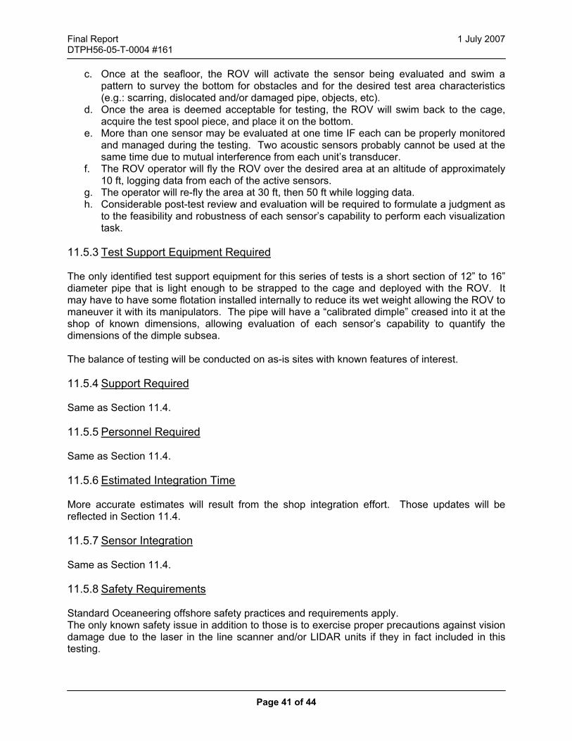
Final Report 1 July 2007 DTPH56-05-T-0004 #161
Page 41 of 44
c. Once at the seafloor, the ROV will activate the sensor being evaluated and swim a pattern to survey the bottom for obstacles and for the desired test area characteristics (e.g.: scarring, dislocated and/or damaged pipe, objects, etc).
d. Once the area is deemed acceptable for testing, the ROV will swim back to the cage, acquire the test spool piece, and place it on the bottom.
e. More than one sensor may be evaluated at one time IF each can be properly monitored and managed during the testing. Two acoustic sensors probably cannot be used at the same time due to mutual interference from each unit’s transducer.
f. The ROV operator will fly the ROV over the desired area at an altitude of approximately 10 ft, logging data from each of the active sensors.
g. The operator will re-fly the area at 30 ft, then 50 ft while logging data. h. Considerable post-test review and evaluation will be required to formulate a judgment as
to the feasibility and robustness of each sensor’s capability to perform each visualization task.
11.5.3 Test Support Equipment Required The only identified test support equipment for this series of tests is a short section of 12” to 16” diameter pipe that is light enough to be strapped to the cage and deployed with the ROV. It may have to have some flotation installed internally to reduce its wet weight allowing the ROV to maneuver it with its manipulators. The pipe will have a “calibrated dimple” creased into it at the shop of known dimensions, allowing evaluation of each sensor’s capability to quantify the dimensions of the dimple subsea. The balance of testing will be conducted on as-is sites with known features of interest. 11.5.4 Support Required Same as Section 11.4. 11.5.5 Personnel Required Same as Section 11.4. 11.5.6 Estimated Integration Time More accurate estimates will result from the shop integration effort. Those updates will be reflected in Section 11.4. 11.5.7 Sensor Integration Same as Section 11.4. 11.5.8 Safety Requirements Standard Oceaneering offshore safety practices and requirements apply. The only known safety issue in addition to those is to exercise proper precautions against vision damage due to the laser in the line scanner and/or LIDAR units if they in fact included in this testing.

Final Report 1 July 2007 DTPH56-05-T-0004 #161
Page 42 of 44
11.5.9 Other Requirements None identified. 11.6 Control and Reporting Procedures 11.7 Pre-Test 11.7.1 Test Plans & Procedures A guideline informal test procedure is prepared for each of the detailed test plans after integration and prior to mobilization. The generic procedures given in the Detailed Test Plan sections above provide the framework to which information learned during the integration phase will be added. The Oceaneering project manager and engineer are responsible for generating the procedure, as well as obtaining any necessary customer or regulatory approvals. 11.7.2 Test Readiness Review (TRR) The formality and scope of a TRR at Oceaneering depends very much on the complexity of a specific project. Successful shop checkout of equipment integrated to an ROV will suffice in lieu of a formal TRR. A toolbox meeting to review the day’s planned activities and safety points will precede each day. 11.8 Test Conduct 11.8.1 Test Plans & Procedures Each test is accomplished in accordance with the final test procedure. Test procedures can be modified during testing as directed by the Project Manager or Project Engineer to address issues that almost always arise during at-sea testing. 11.8.2 Anomaly/Failure Reporting, Analysis and Corrective Action Some of the most useful aspects of testing new hardware are the ability to glean “Lessons Learned” information. This information usually arises from some anomaly or failure during testing. Any anomalous observations or step failures of either test hardware or support hardware must be diligently logged with a thorough description of the event. The Project Manager will review the log and determine whether it warrants further action 11.9 Post Test 11.9.1 Test Reports Each test is concluded with a formal test report that summarizes the test execution. It discusses any anomalies observed and failures with respective corrective actions. The “Test Report” guides the reader towards an understanding of how each sensor performed each aspect of its evaluation. It also includes further reduced data, evaluation, and judgment regarding its suitability as an overall system to be integrated into a robust feasible pipeline inspection UUV.

Final Report 1 July 2007 DTPH56-05-T-0004 #161
Page 43 of 44
11.9.2 Safety The offshore industry is unforgiving of mistakes. Opportunities abound for lapses in diligence to escalate into a serious hazard that places people and equipment at risk. The shop environment also presents risks. Oceaneering is committed to a safe working environment and the safety of its employees both on and offshore. Potential customer representatives should review the following information to familiarize themselves with what to expect, and what will be expected of them. Work onboard is usually dirty. Most technicians will wear jumpsuits (e.g.: Dickies). Contact an Oceaneering representative with any questions about what to bring, where to arrive, etc. As the date for testing nears, an Oceaneering representative will become a point of contact to all personnel expecting to travel onboard during the at-sea testing. Oceaneering Facility Safety Personnel Protective Equipment (PPE) is required for all personnel outside of office workspaces. As a minimum, safety glasses and steel toed shoes are required. Oceaneering has safety glasses and toe protectors that personnel may use if they do not have their own. Guests must be escorted in shop spaces. Personnel Safety Onboard Oceaneering Vessels Visitors to Oceaneering vessels (and most work vessels in general) are expected to board with their own PPE. Basic PPE onboard are:
• Safety Glasses (two pair are recommended – clear, for indoors as well as safety sunglasses for use on deck).
• Steel toe boots with oil-resistant soles. They must have a raised heel (to prevent slipping over ladder rungs).
• Hardhat. In addition to PPE, persons staying aboard Oceaneering vessels are one of two classes:
• Observers, • Workers
Personnel intending to work are required to take “Safe Gulf” training, available from many sources. Safe Gulf provides one with an overview of what to expect and how to conduct ones self onboard. Those onboard without Safe Gulf training require escort at all times. Safe Gulf is required of Oceaneering employees because its people’s safety is crucial to the success of the company. We believe that personnel planning to attend the offshore testing should attend Safe Gulf training.

Final Report 1 July 2007 DTPH56-05-T-0004 #161
Page 44 of 44
12 Glossary Analysis Analysis uses computational methods to show that an item
performs within its required parameters. AUV “Autonomous Underwater Vehicle” -- AUVs are programmed with a
desired mission, launched, and then execute their mission without further supervisory input.
COTS “Commercial Off The Shelf” item. A standard catalog item that one could readily buy from a commercial vendor.
Demonstration Demonstration is defined as an exhibition of the operability of an item under intended service use conditions. Demonstration will be used to evaluate a sensor’s performance with respect to specific criteria. Demonstrations are not associated with a “measurement” or “tolerance”, but rather exhibit a binary “pass” or “fail.”
FORJ “Fiber Optic Rotary Joint” – used permits a winch to use a fiber optic tether.
Inspection Inspection uses visual methods to verify that specified design features and manufacturing procedures (e.g.: marking, de-burring) have been accomplished. In the context of this evaluation, inspection will be used to assay items such as each sensor’s ability to be integrated into the ROV, ease of installation, usability of human interfaces, etc.
OSV PPE “Personnel Protective Equipment” – Items such as safety glasses,
steel toed boots, etc intended to protect someone from hazards that cannot be removed from the workplace.
ROV “Remotely Operated Vehicle” -- TBD “To Be Determined.” The whole issue or value is undetermined and
not estimated. It may be eliminated entirely. TBR “To Be Reviewed.” Similar to TBD. Interpret as “this is the intent
and the estimated value, pending some approval authority (e.g.: customer, management, etc).
Test Testing measures specification values or operational requirements by means of functional, parametric, or environmental tests of the equipment or software. Tests involve the use of instrumentation to acquire and record data. “Testing” requires a one-to-one correlation between a requirement and a measurement (or sometimes to reduced data from raw measurements), with the measured value clearly falling between specified upper and lower bounds. Those bounds will reflect guidelines and goals for this evaluation, rather than hard requirements.
TRR “Test Readiness Review” – Review prior to testing to verify that all engineering, manufacturing, commercial, and safety prerequisites are met for the test article, test support facility, and personnel.