final report - ceias.nau.edu
TRANSCRIPT

Human Powered Vehicle Challenge
By:
Team 16 Yousef Alanzi, Evan Bunce, Cody Chenoweth, Haley Flenner, Brent Ives, and Connor Newcomer
Final Report Document
Submitted towards partial fulfillment of the requirements for ASME Human Powered Vehicle Competition
4/22/20164/24/2016
Department of Mechanical Engineering Northern Arizona University
Flagstaff, AZ 86011

Table of Contents Abstract ………………………………………………………………………………………...…3 1.0 Introduction……………………………………………………………………………………4
1.1 Client…………………………………………………………………………………..4 1.2 Problem Description……………………………………………………………..……4 1.3 State of the Art Research………………………………………………………...……4
2.0 Problem Formulation………………………………………………………………….………4 2.1 Identification of Need…………………………………………………………………4 2.2 Project Goal………………………………………………………………………...…4 2.3 Objectives……………………………………………………………………..………5 2.4 Operating Environment……………………………………………………………..…5 2.5 Constraints………………………………………………………………………….…5 2.6 Quality Function Deployment……………………………………………… ……56 2.7 House of Quality…………………………………………………………………...……6
3.0 Proposed Design………………………………………………………………………………7 3.1 Frame Design…………………………………………………………………….…79 3.2 Fairing Design…………………………………………………………………..…910 3.3 Steering Design………………………………………………………………..…1011 3.5 Drivetrain Design……………………………………………………………………11 3.6 Innovation Design……………………………………………………………..…1112
4.0 Analysis………………………………………………………………………………..….…12 4.1 Crash simulation Analysis……………………………………………………..….…12 4.2 Frame Analysis………………………………………………………………...…1213 4.3 Steering Knuckle Analysis…………………………………………………….…1314 4.4 Aerodynamic Analysis…………………………………………………...………1516 4.5 ANSYS simulation………………………………………………………….……1618
5.0 Cost Analysis………………………………………………………………………..….……17 7.1 Bill of Materials………………………………………………………………..…1718 7.2 Manufacturing Costs…………………………………………………………………18
6.0 Conclusions……………………………………………………………………………….….19 References……………………………………………………………………………………..…20
1

Abstract
The purpose of this project is to engineer an efficient and reliable human powered vehicle that is capable of transporting both goods and people, and of traveling a relatively large distance. This technology is very desirable, especially in underdeveloped countries that lack the infrastructure to support public transportation or a readily available fuel source for cars. This project aims to design a safe, efficient, and reliable vehicle that can be propelled solely by the vehicle’s rider and requires no external fuel sources.
The main criteria taken into account for the vehicle design are the frame design, steering geometry, material of construction, power input, fairing design, and seating position. The most important design considerations were deemed to be strength, weight, efficiency, and ease of manufacturing.
The frame is constructed of 4130 Chromoly steel; this was chosen due to its stiffness, strength, and low deflections during welding. It is comprised of a single main support running the entire length of the vehicle that all the individual components are attached to and reinforced with gusset plates at strategic locations to help maximize its strength. The fairing has an ellipsoid design following similar principles of an airfoil to minimize drag forces acting upon it. Standard bicycle cranks and footpedals will provide the power input necessary to propel the vehicle. The seat has a one piece design that is able to accommodate riders of any height by attaching to the frame with a fully adjustable bracket. The steering system was designed for stability and efficiency, with a close approximation to Ackerman geometry, nearzero scrub radius, zero camber, and moderate mechanical trail. The knuckles are a doubleclamp design for greater stiffness and better control of braking forces.
2

1.0 Introduction 1.1 Client
The American Society of Mechanical Engineers (ASME) commissioned this build and
sponsors the competition every year in which schools from all over the country come to compete and showcase their designs. They provide the general guidelines and outline the requirements for each competition and are responsible for judging and scoring the individual events.
1.2 Problem Description
Each year ASME hosts a competition for students to put their skills to the test. The competition is comprised of a combination of endurance, drag race, and sprint events. The competitions are designed to test every aspect of the vehicle. They simulate an urban environment and contain obstacles such as speed bumps, cobblestones, and a slalom lane. They are designed to assess the vehicle's speed and maneuverability by judging the vehicles ability to maneuver obstacles such as hairpin turns and long straightaways.
1.3 State of the Art Research
Most competition vehicles are typically made of a combination of both metal alloys and composites that utilize a recumbent riding position to help streamline the vehicle and minimize aerodynamic effects. Some of the latest and most innovative vehicle designs generate and store power for later use.
2.0 Problem Formulation
2.1 Identification of Need
Most underdeveloped countries that lack infrastructure and public transit rely on a form of a human powered or primitive vehicle for transportation. These typically include bicycles and motorbikes that can be very dangerous. These countries require a human powered vehicle that is efficient, reliable, and safe that can operate over any terrain and in any type of weather.
2.2 Project Goal The goal is to design and manufacture a human powered vehicle so that it meets the
ASME Human Powered Vehicle competition requirements. To do this the vehicle must be as light, strong, and fast as possible so that it is competitive in every event in which it is entered.
3

2.3 Objectives Objectives for the build include producing a lightweight and innovative vehicle that is
our own original design, maximizing its efficiency so that it can travel the greatest distance with the least amount of power input, operating within an acceptable factor of safety, and being durable and easy to operate for all ages, heights, and sizes.
2.4 Operating Environment This vehicle must be capable of operating under every condition imaginable. It must be
able to handle varying terrain from paved roads to dirt roads. It must also be able to withstand different weather conditions from sunshine to rain to snow, thus the fairing is a must to keep the rider comfortable. Since the goal is to deploy them to rural areas there is no telling the amount of abuse they may be subjected to. The vehicle must be durable and easy to repair if necessary by using standard bike components that are readily available.
2.5 Constraints
Constraints include not being able to use any vehicles from previous years, and it must be
able to compete in both the speed and endurance events at the competition. The vehicle must be designed to meet the minimum safety requirements which include having the rider protected in the event that the vehicle is subjected to both a roll over and tipping onto its side. The rider must have a full 180 degree field of vision while sitting inside and demonstrate some sort or technical innovation.
2.6 Quality Function Deployment
The quality function deployment (QFD) is a tool that aids in relating customer needs to engineering requirements. Ten customer needs were developed as per the ASME HPV website and rules. Following these customer needs, ten additional design requirements were also developed. By use of a QFD as shown in Table 1, all twenty of these criteria were related to each other. It can be seen that safety in particular will be the most important design requirement to consider due to the fact that it is associated with four of the customer needs. Other notable design requirements include durability and maneuverability which each relate to three of the customer needs.
4

Table 1: Quality Function Deployment
2.7 House of Quality
The house of quality is similar to the QFD in that it relates design requirements to each other instead of the customer needs as the QFD does. Notably, the house of quality shows that safety is again related to five other design requirements (Table 2). High strength and lightweight also had a positive correlation, as well as high velocity and light weight.
Table 2: House of Quality
5

3.0 Proposed Design
Figure 1: Current Design Progress
3.1 Frame Design
The frame seen in Figure 1 is the final design and was constructed using Chromoly steel
tubing with 1.25 inch outer diameter and a wall thickness of 0.083 inches. This material was chosen due to its high stiffness and ease of manufacturing; using steel eliminates the need for a welding fixture or heat treatment after fabrication. The steel tubes were cut to length, notched, and laid in place as seen below in Figure 2 to mock up the rough shape of the frame.
6

Figure 2: Assembly Process
The frame was welded together using a Tungsten Inert Gas (TIG) welder as seen in Figure 3. Each weld required accurate angle precision for the support arms and the roll cage to ensure proper alignment.
Figure 3: TIG Welder
The main structure of the frame consists of a long main support running down the length of the vehicle from front to back with two side arms at the front in which the wheels attach to. The side
7

arms are welded 15 degrees from horizontal and five inches from the second sprocket to avoid any interference with the chain. This can be seen below in Figure 4.
Figure 4: Side Arms Welding Configuration
Holes were drilled two inches apart along the main tube for adjustable seat positioning and end at the base of the roll cage. The roll cage is shaped like a coffin and has bends at the midpoint (70 degrees) and at the top (54 degrees). The roll cage is also angled 12 degrees from vertical towards the rear wheel and supported with two rear beams to prevent any buckling. Dropouts were machined on CNC mills and then welded on the insides of the rear support beams to hold the rear wheel. One dropout was manufactured with holes for a derailleur hanger to be attached and is shown in Figure 5.
Figure 5: Rear Wheel Dropout
8

3.2 Fairing Design
The design of the fairing resembles an ellipsoid shaped and symmetrical on both sides, seen in Figure 6, to reduce turbulent flow zones. The purpose of this fairing is to minimize the drag forces acting on the vehicle that cause it to travel slower and make the rider exert more energy to keep the vehicle at constant speed. The fairing is 120 inches in length and 40 inches in height and width. It is constructed from fiberglass and has approximately 3 layers of material with reinforcement in areas with high stress concentrations. The fairing has a windshield and two side windows to give the driver the maximum amount of visibility. The driver enters the vehicle from a side door that opens from the rear and is hinged at the front.
Figure 6: Fairing Design
3.3 Steering Design
The steering system was designed primarily for stability, efficiency, and ease of
manufacturing. The basis of the system is a sixbar Ackerman setup, approximated by designing the steering arms such that the drag link connections lie on axes running from the center of the rear wheel to the kingpins. Kinetic steering models were not considered in the design due to the relatively low speeds, light weights, and low slip angles inherent to humanpowered transportation. The steering geometry was set up to coincide with perfect Ackerman geometry for the vehicle’s minimum turning radius, calculated to be roughly twelve feet. This consideration for the minimum radius is due to efficiency concerns: the vehicle will be moving at its slowest speeds in its tightest turns and will therefore have a minimal amount of weight transfer between front wheels, meaning that the slip angles of the front tires will remain roughly
9

equal, which in turn means that all wheels ought to be moving about a common center. Conversely, in wider, high speed turns Ackerman geometry is less important due to the limited amount of tire slippage and a higher degree of weight transfer.
The steering system is stabilized by offsetting the tire contact patch from the steering axis from both the lateral and frontal view. With this offset the force of the road surface on the tire creates a moment arm about the steering axis. In the lateral view, this offset, the mechanical trail, causes the wheels to selfcenter. Trail is set at 2.13 inches by means of a caster angle of 12 degrees. The caster angle also causes camber loss during cornering, helping the wheel to handle the lateral forces of the turn. The scrub radius, the offset from the frontal view, is almost zero. Theoretically zero scrub radius is most desirable as it eliminates bump steer and brake jack; in reality such geometry causes twitchiness and instability. A small scrub radius establishes the previously mentioned moment arms, which, due to the symmetry of the vehicle, act against each other to stabilize the steering. The scrub radius of this vehicle is set to 0.278 inches to both combat unwanted steering inputs and promote stability.
This vehicle has zero camber. While such a setup is not necessarily conducive to racing, the considerations of stability and efficiency override cornering ability. Positive camber does nothing good for modern vehicles and negative camber forces round bicycle tires to operate at a small slip angle, increasing friction and decreasing stability.
3.4 Drivetrain Design
The vehicle's drivetrain is comprised of three sets of chain rings and three separate chains. The positioning of the front bottom brackets is shown in Figure 7. The setup is based on a 3x10 drivetrain from a mountain bike. While it is commonly known that there is a large amount of gear overlap in those systems, it is also the most versatile across a wide range of speeds. Lower gearing can be used for quick starts such as the drag race, while the mid and higher ranges are useful in the endurance event. It will have 2 derailleurs; one on the front crankset and another on the cassette. Gear changes are accomplished through grip shifters on the steering handles, chosen for their intuitive operation.
10

Figure 7: Front Bottom Brackets
3.6 Innovation Design
The basic problem of pedaling a fully enclosed vehicle is that there is no airflow across the rider so they quickly overheat. Adding airflow increases the drag force; consider the extreme case, in which the maximum possible airflow is achieved by removing the fairing completely, which unfortunately also maximizes drag. The first consideration in aiding cooling without hurting drag is where to direct the airflow for maximum effect so that the rider can use a smaller amount of it.
The solution involves simple biology: the body carries heat through the bloodstream. Therefore, the best places to remove heat from the body are where there's a large amount of blood flow close to the surface of the skin, such as the feet, groin, armpits, spinal region, and head. The rider’s feet cannot be cooled because of cycling shoes, and there isn’t a good way to direct airflow across the groin because of the motion of the rider’s legs. The armpits aren't a good option because the rider’s arms will be at their side, and most shirts are baggy in that region, inhibiting heat transfer. The head is covered by a helmet, which, while ventilated, wouldn't benefit much from increased airflow. That leaves the spine; any heat transfer out of that region makes a huge impact on what the rest of your body feels, so the best route for airflow is across the rider's back.
There is no good way for the air to come in from the sides without creating an unwanted turbulent zone in the middle of the seat, right where good flow is needed, so air must be directed up from the bottom of the seat. This is accomplished with a pair of submerged inlets on the bottom of the fairing pulling air into a duct running through the seat, which is highly perforated.
11

The exit of the ductwork is on the top of the fairing in a lowpressure area, creating a pressure differential that accelerates the flow through the seat. While untested, this concept should create a significant cooling effect.
4.0 Analysis
The load analysis was completed using ANSYS to analyze the maximum deflection of the frame as well as load testing the roll cage. Solidworks was used for the computational fluid dynamics analysis of the vehicles fairing. Running both simulations gave us results that were well within range for engineering calculation purposes.
4.1 Crash Simulation Analysis
To meet the requirements of the competition a simulation of a crash must be completed for both scenarios of tipping as well as rolling. To conduct this testing a load was applied at various locations around the roll cage. To simulate a rollover a load was applied directly to the top and there was no significant deflection therefore the roll cage passed and the rider would be protected and have no contact with the ground while strapped into the seat. The testing for the side impact was simulated by placing a load directly on the side of the vehicle in the location that would impact first in the event it lands on its side. Once again the deflection was negligible and the rider's shoulders and torso would be protected from any direct contact with the ground.
4.2 Frame Analysis
To ensure the frame would not fail at any joints, test welds were conducted to prove welding capabilities. Test welds were conducted using Chromoly steel as simulations of joints. The joints were inspected to ensure full penetration between the two surfaces and failure happened at the material before the weld. If the weld broke before the material, the weld failed. Figure 8 shows a weld test conducted that broke at the material before the weld.
12

Figure 8: Test weld
4.3 Steering Knuckle Analysis
The steering knuckles were subjected to FEA analysis within SolidWorks under two loading cases. The first, shown in Figure 9, assumes a 300 lbf load upward on the hub while the steerer clamps are fixed, which exceeds the highest impulse the knuckles are expected to face. The highest stress concentration is at the bottom of the shoulder on the hub. Unfortunately this concentration cannot be removed as commercial wheel design dictates the shape of that feature. As the figure shows, however, the yield strength of the material is over 8 times higher than the stress at that point, so there is no danger inherent in this design.
13
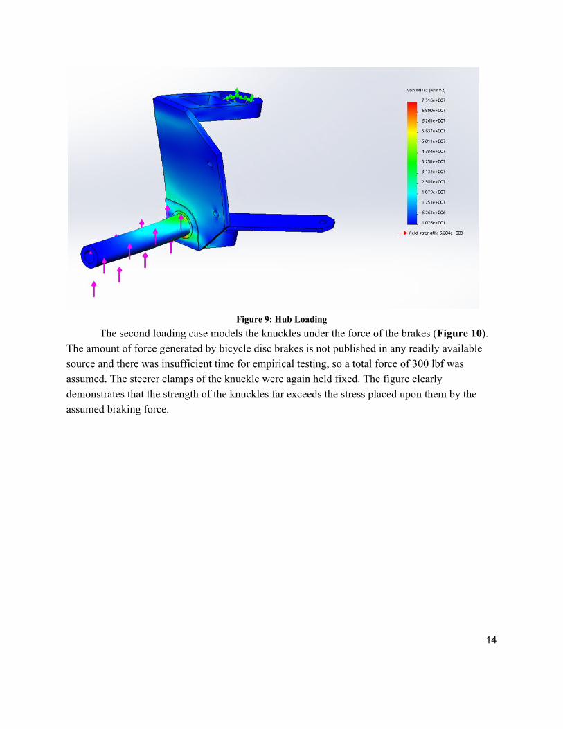
Figure 9: Hub Loading
The second loading case models the knuckles under the force of the brakes (Figure 10). The amount of force generated by bicycle disc brakes is not published in any readily available source and there was insufficient time for empirical testing, so a total force of 300 lbf was assumed. The steerer clamps of the knuckle were again held fixed. The figure clearly demonstrates that the strength of the knuckles far exceeds the stress placed upon them by the assumed braking force.
14

Figure 10: Brake Loading
It is understood that there is no need for the steering knuckles to operate at such high
factors of safety. However, the driving consideration of the design team was not performance but available manufacturing time, which forced the knuckle design towards manufacturing simplicity. Therefore, individual components have largely uniform cross sections and minimal lightweighting.
4.4 Aerodynamic Analysis
The aerodynamic simulation for the fairing was done in SolidWorks and is shown in Figure 11. The fairing was placed in a simulated wind tunnel cube with dimensions (5m x 5m x 5m). The simulation measured the external flow rate using standard air density and atmospheric air pressure. The standard air density (1.225 kg/m^3) and atmospheric air pressure (101.325 kPa) were considered at sea level, since the competition is hosted in California. A velocity of 9 m/s was assumed for the simulation due to the weight of the frame. The coefficient of drag was calculated to be 0.0577 using Equation 1.
[1]
15

Figure 11: Air flow on Fairing
4.5 ANSYS Simulation
The deflection of the frame was simulated using ANSYS and is shown in Figure 12. The frame was drawn using lines to simulate the circular tubing of the frame and was defined with a set outer diameter (1.25 in) and a wall thickness (0.083). The lines are meshed together to simulate the frame being welded together. A load of 400 pounds was set in the middle of the frame to simulate someone sitting in it. The front arms and rear beams were set as the displacements reactions to simulate the wheel placements. The deflection resulted in the middle of the frame at 0.33 inches.
16

Figure 12: Deflection Simulation 1
The second simulation composed of three loads applied to the frame to determine the deflection. A 600 pound load was applied from the top, 300 pound load from the right side of the roll cage, and a rider load of 250 pounds located at the center of the main member. The resulting deflection is shown in Figure 13 and resulted in 0.48 inch downwards; located in the middle of the frame.
17

Figure 13: Deflection Simulation 2
From the ANSYS simulations the deflection of the frame is not considered to fail due to the overall material properties of Chromoly. However, the overall deflection of the frame is still considerable which results in welding gusset plates at the critical deflection points.
18

4.0 Cost Analysis 7.1 Bill of Materials
Table 3: Current Bill of Materials
At the current point in the project, the table above shows all of the parts that have been purchased within the ASME budget allotted to the Human Powered vehicle. The budget still remains on track with the original plan to manufacture the vehicle.
7.2 Manufacturing Costs
The table below shows a breakdown of the handson work that was put into creating the vehicle that is still currently in process. Each job has a price per hour which is shown, and this is the standard for all engineering projects including the human powered vehicle.
19

Table 5: Costs to Manufacture Current Product
5.0 Testing
There was a minimal amount of testing performed during the fabrication of the vehicle. Specifically, a test weld on the tubing used for the frame was subjected to destructive testing to ensure the integrity of the frame.
20
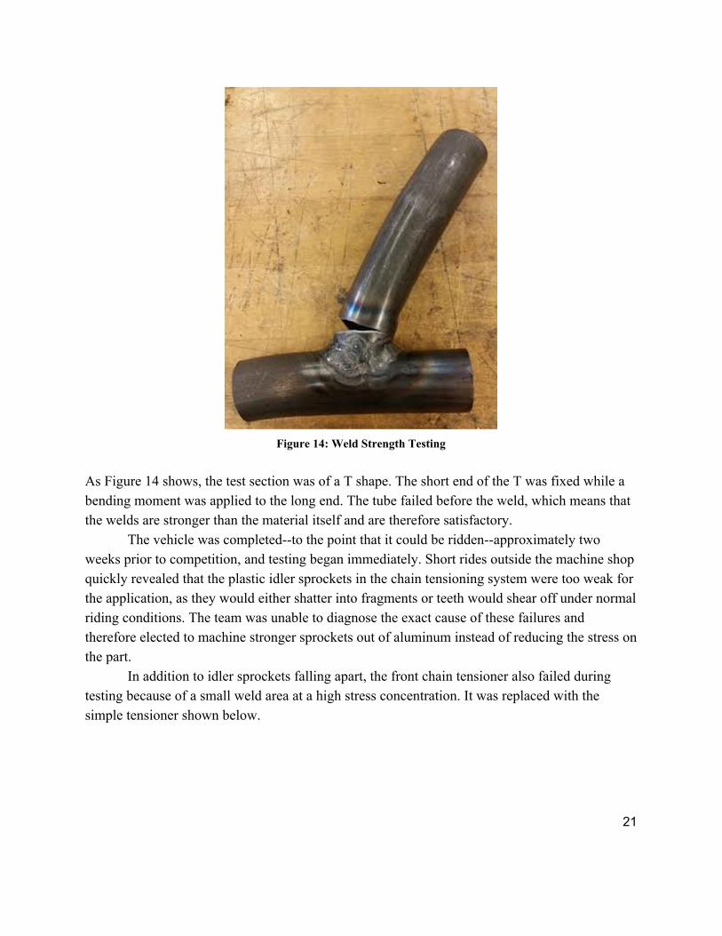
Figure 14: Weld Strength Testing
As Figure 14 shows, the test section was of a T shape. The short end of the T was fixed while a bending moment was applied to the long end. The tube failed before the weld, which means that the welds are stronger than the material itself and are therefore satisfactory.
The vehicle was completedto the point that it could be riddenapproximately two weeks prior to competition, and testing began immediately. Short rides outside the machine shop quickly revealed that the plastic idler sprockets in the chain tensioning system were too weak for the application, as they would either shatter into fragments or teeth would shear off under normal riding conditions. The team was unable to diagnose the exact cause of these failures and therefore elected to machine stronger sprockets out of aluminum instead of reducing the stress on the part.
In addition to idler sprockets falling apart, the front chain tensioner also failed during testing because of a small weld area at a high stress concentration. It was replaced with the simple tensioner shown below.
21

Figure 15: Chain Tensioner and Aluminum Sprocket
This tensioner is also using one of the team’s custommade aluminum idler sprockets.
Once the immediate issues were resolved, the team devised a test circuit that mimicked the layout of the endurance challenge at the HPV competition. The team then created a timetrial race series by inviting all comers to race the circuit for a recorded time. Times were recorded in a public space in the machine shop to encourage competition amongst students and thereby ensure a high level of stress on the vehicle. Modifications to the vehicle were tracked alongside lap times to validate the improvements.
22

Figure 16: Lap Times and Modifications
The final area in which design iteration was necessary was the tie rods. The original
design called for sleeved aluminum tie rods, but those repeatedly bent at the threads just inboard of the rodend joints. The next design used 0.25 inch steel rods with 0.5 inch aluminum sleeves, but those also bent at the threads. The cause of failure was the small diameter and high stress concentration at the threads of the rods, but was not discovered in time to properly resolve the issue by ordering larger rodend joints. The final design, which held up through competition, was 0.375 inch steel rods necked down to 0.25 inches at the ends, with large steel sleeves over both the rod and the joint. The sleeves prevented the tie rods from buckling at the threads, their weakest section.
Vehicle testing was a highly instructive experience for the team. Once the vehicle was rolled out of the shop and ridden it became immediately obvious where the weak links in the
23

design hid. Fixing those weak links provided additional opportunities to apply the engineering design process in microcosm.
6.0 Results of Competition
Category Ranking (out of 32)
Design presentation 21
Innovation 19
Women’s speed event 13
Men’s speed event 20
Endurance challenge 20
Overall 21
Table 6. Results
After experiencing a couple minor issues with the bike chain and tires, the NAU Human Powered Vehicle team placed 21st overall out of 32 vehicles.
7.0 Conclusions
It was concluded that the vehicle layout resulting in the best performance and highest efficiency in all competition categories is a recumbent tadpole tricycletwo wheels in the front and one in the back. The drivetrain is a mountain bike 3x10 system for versatility across a wide
24
range of situations. The frame is made out of Chromoly steel because of its stiffness and manufacturability. It can also reduce any possible injuries to the rider and reduce the frame from getting damaged in the case of an accident. The steering system was designed to be stable and efficient through an approximation of Ackerman geometry, nearzero scrub radius, moderate trail, and zero camber. The fairing was designed to provide safety to the rider in case of any outside forces and lower the drag force of the vehicle. Over all this vehicle is capable of operating under any road conditions and is viable option to supplement travel in rural areas of the world.
25

References American Society of Mechanical Engineers . n.d. <https://www.asme.org/aboutasme>
Dieter, George. Engineering Design: A Materials and Processing Approach. New York: McGrawHill, 1983.
"The Recumbent Bicycle and Human Powered Vehicle Information Center." The Recumbent Bicycle and Human Powered Vehicle Information Center. N.p., n.d. Web. 23 Sept. 2015.
26