final project report: reducing california pv balance of ... · san rafael, ca 94901 ... lated...
TRANSCRIPT

www.CalSolarResearch.ca.gov
Final Project Report:
Reducing California PV Balance
of System Costs by Automating
Array Design, Engineering, and
Component Delivery
Grantee:
SunLink Corporation
February 2013
California Solar Initiative
Research, Development, Demonstration
and Deployment Program RD&D:
PREPARED BY
1010 B Street, Suite 400 San Rafael, CA 94901
Principal Investigator: Mike Williams [email protected] 415-306-9836
Project Partners: Pacific Earthquake Engineering Research Center Rutherford and Chekene Autodesk Computers and Structures, Inc.
PREPARED FOR
California Public Utilities Commission California Solar Initiative: Research, Development, Demonstration, and Deployment Program
CSI RD&D PROGRAM MANAGER
Program Manager: Ann Peterson [email protected]
Project Manager: Smita Gupta [email protected]
Additional information and links to project related documents can be found at http://www.calsolarresearch.ca.gov/Funded-Projects/
DISCLAIMER
“Any opinions, findings, and conclusions or recommendations expressed in this material are those of the author(s) and do not necessarily reflect the views of the CPUC, Itron, Inc. or the CSI RD&D Program.”

Preface
The goal of the California Solar Initiative (CSI) Research, Development, Demonstration, and Deployment (RD&D) Program is to foster a sustainable and self-supporting customer-sited solar market. To achieve this, the California Legislature authorized the California Public Utilities Commission (CPUC) to allocate $50 million of the CSI budget to an RD&D program. Strategically, the RD&D program seeks to leverage cost-sharing funds from other state, federal and private research entities, and targets activities across these four stages:
Grid integration, storage, and metering: 50-65%
Production technologies: 10-25%
Business development and deployment: 10-20%
Integration of energy efficiency, demand response, and storage with photovoltaics (PV)
There are seven key principles that guide the CSI RD&D Program:
1. Improve the economics of solar technologies by reducing technology costs and increasing system performance;
2. Focus on issues that directly benefit California, and that may not be funded by others;
3. Fill knowledge gaps to enable successful, wide-scale deployment of solar distributed generation technologies;
4. Overcome significant barriers to technology adoption;
5. Take advantage of California’s wealth of data from past, current, and future installations to fulfill the above;
6. Provide bridge funding to help promising solar technologies transition from a pre-commercial state to full commercial viability; and
7. Support efforts to address the integration of distributed solar power into the grid in order to maximize its value to California ratepayers.
For more information about the CSI RD&D Program, please visit the program web site at www.calsolarresearch.ca.gov.
SunLink Corporation Page 2 of 42 CSI Final Report
Table of Contents Abstract ............................................................................................................................................ 4 Acknowledgements ......................................................................................................................... 5 Glossary ........................................................................................................................................... 6 Executive Summary ......................................................................................................................... 7 1 Introduction ............................................................................................................................. 12
1.1 SunLink .......................................................................................................................... 12 1.2 SunLink Products ........................................................................................................... 12 1.3 SEAOC Code Committee .............................................................................................. 12 1.4 Meeting CSI Principles .................................................................................................. 13 1.5 Summary ....................................................................................................................... 13
2 Automation -- Structural analysis and design automation ...................................................... 14 2.1 Overview of SunLink’s Array Design Process ............................................................... 14 2.2 Advantages of Automation ............................................................................................ 14 2.3 Automation Challenges and Best Practice Recommendations ..................................... 15
2.3.1 Development path and prioritization .......................................................................... 16 2.3.2 Testing, bug fixes, and quality assurance ................................................................. 16 2.3.3 Backward compatibility .............................................................................................. 16 2.3.4 Integration and compatibility with commercial software ............................................ 17 2.3.5 Training and documentation ...................................................................................... 17
2.4 Software Choices ........................................................................................................... 17 2.4.1 Computer-aided design (CAD) software .................................................................... 17 2.4.2 Structural Analysis Software ...................................................................................... 18 2.4.3 SunLink Design Studio .............................................................................................. 18 2.4.4 Engineering Data Mart ............................................................................................... 18 2.4.5 Summary ................................................................................................................... 18
3 Document Management System ............................................................................................ 19 3.1 Scope ............................................................................................................................. 19 3.2 Requirements & Evaluation Criteria .............................................................................. 19
3.2.1 Document Management Functionality Criteria .......................................................... 19 3.2.2 SunLink / Solar Industry Specific Functionality Criteria ............................................. 20
3.3 Software Evaluation ....................................................................................................... 20 3.4 Software Selection ......................................................................................................... 21
3.4.1 M-Files DMS Overview .............................................................................................. 21 3.5 SunLink Pilot .................................................................................................................. 21
3.5.1 Detail Pilot Scope ...................................................................................................... 21 3.5.2 Pilot Team & Departments......................................................................................... 22 3.5.3 Pilot Workshops ......................................................................................................... 22 3.5.4 Pilot Workshop Deliverables ...................................................................................... 22 3.5.5 Pilot DMS Environment Configuration ....................................................................... 22 3.5.6 User Configuration ..................................................................................................... 22 3.5.7 Workflow Configuration.............................................................................................. 23 3.5.8 Document Configuration ............................................................................................ 23 3.5.9 Metadata Configuration ............................................................................................. 23 3.5.10 Views ..................................................................................................................... 24 3.5.11 Reports .................................................................................................................. 24 3.5.12 Pilot Execution ....................................................................................................... 24
3.6 Pilot Outcome / Results ................................................................................................. 24 3.6.1 Pilot Team Feedback ................................................................................................. 25 3.6.2 Benefits of a Structured DMS .................................................................................... 25 3.6.3 Lessons Learned ....................................................................................................... 25
3.7 Conclusions regarding DMS in Solar Industry ............................................................... 26 4 Seismic Testing and Analysis................................................................................................. 27

SunLink Corporation Page 3 of 42 CSI Final Report
4.1 Project Approach ........................................................................................................... 27 4.1.1 Experimental Roof Motions ....................................................................................... 27 4.1.2 Matrix of Tests ........................................................................................................... 28 4.1.3 Execution of Tests ..................................................................................................... 28 4.1.4 Gathering of Test Data .............................................................................................. 28 4.1.5 Computer Model Validation ....................................................................................... 28
4.2 Project Outcomes .......................................................................................................... 29 4.3 Conclusion ..................................................................................................................... 29 4.4 Recommendations ......................................................................................................... 29 4.5 Public Benefits to California ........................................................................................... 29
5 Database – California Agency Permit Document Requirements Database ........................... 30 5.1 California Agency Web Application Project Overview ................................................... 31
5.1.1 Purpose and Goals .................................................................................................... 31 5.1.2 Challenges ................................................................................................................. 31 5.1.3 Platform...................................................................................................................... 31
5.2 California Agency Web Application Functionality .......................................................... 31 5.2.1 Search........................................................................................................................ 32 5.2.2 Community Information .............................................................................................. 32 5.2.3 Agency Contact ......................................................................................................... 32 5.2.4 Personnel Contact ..................................................................................................... 32 5.2.5 Permit Data ................................................................................................................ 32 5.2.6 Documentation and Links .......................................................................................... 33
5.3 Database Login with Administrator Privileges ............................................................... 33 5.3.1 Search........................................................................................................................ 33 5.3.2 Community Information .............................................................................................. 33 5.3.3 Agency Contact ......................................................................................................... 34 5.3.4 Personnel Contact ..................................................................................................... 34 5.3.5 Permit Data ................................................................................................................ 34 5.3.6 Documentation and Links .......................................................................................... 34 5.3.7 Web Application Manager.......................................................................................... 34
5.4 California Agency Web Application Development Completed Milestones .................... 35 6 Recommendations ................................................................................................................. 36
6.1 Engineering Automation ................................................................................................ 36 6.2 Process Definition and Automation ............................................................................... 36 6.3 Full Scale Laboratory Testing ........................................................................................ 37 6.4 Organization and Access to Fragmented Information ................................................... 37
7 Public Benefits to California ................................................................................................... 38 7.1 California Agency Permit Document Requirements Database...................................... 38 7.2 Building Code Development for Unattached Solar Arrays ............................................ 38 7.3 Standardization of Permitting Packages........................................................................ 39 7.4 Benefits to the Solar Industry ........................................................................................ 39
8 Conclusions ............................................................................................................................ 40 Technology Transfer – Research Project Knowledge Sharing ..................................................... 41

SunLink Corporation Page 4 of 42 CSI Final Report
Abstract SunLink, a California based company, is a leading provider of PV (photovoltaic)
mounting solutions and other Balance of System (BOS) components to the California and
U.S. markets. SunLink performed research, demonstration and deployment activities
under a CSI (California Solar Initiative) grant entitled “Reducing California PV Balance
of Systems Costs by Automating Array Design, Engineering, and Component Delivery.”
These activities included research and further development of software design tools that
enable automation of system layout and structural design as well as automated
preparation of documentation needed for project approval and installation. Automating
these tasks saves engineering and installation time, improves quality, and broadens the
available market for rooftop solar installations.
Because of the unique aspects of PV arrays, the California Building Code does not
contain specific provisions that allow for optimized structural design of PV arrays. Under
the grant, SunLink extended its existing research to improve its knowledge of seismic
effects on arrays, including verifying analytical models through extensive shake table
testing of full size arrays.
Since SunLink projects occur throughout California, a database of local permitting
requirements was developed under this project, and the database can be expanded as
projects arise in new localities. SunLink and other solar stakeholders can use this
information to facilitate the delivery of documentation that best illustrates to building
officials the code compliance of optimized design, and better meets the requirements of
local permitting agencies in California.
The combination of automated project design and reporting systems based on
demonstrated engineering research, improved access to permitting agencies and officials,
and broad dissemination of the lessons learned during the project, all contribute to
creating additional opportunities for solar array installation in California.

SunLink Corporation Page 5 of 42 CSI Final Report
Acknowledgements SunLink gratefully acknowledges the California Public Utilities Commission (CPUC) for
providing program sponsorship and resources under the California Solar Initiative
Research, Demonstration and Deployment Program Grant Solicitation No. 2.
SunLink also recognizes the contribution of Itron acting as grant manager. In particular,
Smita Gupta and Ann Peterson provided useful and timely guidance and feedback during
the two-year project.
SunLink would like to thank Rutherford and Chekene for performing their grant-related
work in a very professional and timely manner. In particular, Andreas Schellenberg, Joe
Maffei, Marisa Dent, Saeed Fathali, and Karl Telleen all contributed substantially to the
success of the project.
SunLink thanks the technology partners who supported the project ― AutoDesk,
Computers and Structures, Inc., the Pacific Earthquake Engineering Research Center
(PEER). In particular, Wes Neighbour, PEER Senior Development Engineer, was
instrumental to the success of the shake table tests.
SunLink also greatly appreciates the contribution of Melissa Reading for her organized
and professional management of the many reports and deliverables generated during the
project.

SunLink Corporation Page 6 of 42 CSI Final Report
Glossary
AHJ Authority Having Jurisdiction
API Application programming interface
ASCE American Society of Civil Engineers
AWS Amazon Web Services
BOM Bill of Materials
BOS Balance of Systems
BPM Business Process Management
CAD Computer Aided Design
CFD Computational Fluid Dynamics
CPUC California Public Utilities Commission
CRM Customer Relationship Management
CSI California Solar Initiative
DSA Division of the State Architect
DMS Document Management System
EDM Engineering Data Mart
ERP Enterprise Resource Planning
LAN Local Area Network
MATLAB Matrix Laboratory - a numerical computing environment
MCS Mineral Cap Sheet (roofing membrane)
OCR Optical Character Recognition
ODBC Open Database Connectivity
PEER Pacific Earthquake Engineering Research center
PLM Product Lifecycle Management
PV Photovoltaic
PVC Polyvinyl Chloride (roofing membrane)
PV-SAP Photovoltaic Structural Analysis Program
R+C Rutherford and Chekene
RD&D Research, Development, Demonstration and Deployment Program
RMS Roof Mount System
SAP2000 A structural analysis software package
SDS Design spectral response acceleration factor
SEAOC Structural Engineers Association of California
SELA Structural Engineering Load Advisory
SLDS SunLink Design Studio
SugarCRM Customer relationship management product from vendor SugarCRM
SunLink Corporation Page 7 of 42 CSI Final Report
Executive Summary
The California Solar Initiative seeks to establish 3000 megawatt (MW) of distributed
generation in California by 2017. In support of this goal, CSI funded SunLink research to
decrease the engineering costs associated with fully optimized PV systems. This project
included automation of structural engineering, full-scale seismic testing of PV array
behavior, analysis of wind tunnel testing for dynamic modeling of wind loads,
development of a publicly accessible database of permitting agency requirements in
jurisdictions across the State of California, creation of an automated document
management system, and work that will facilitate code updates to overcome barriers to
non-attached (non-roof-penetrating) designs that are necessary for broad building-owner
acceptance of rooftop solar. Each of these separate tasks demonstrates opportunities for
Balance of System cost reduction.
California-based SunLink Corporation is a leading provider of PV mounting solutions
and other balance of system (BOS) components to the California and international
markets. SunLink mounting systems are compatible with a wide range of solar modules.
They are ballasted, flexible, interconnected systems that can be positively attached to the
roof structure when necessary. SunLink projects are thoroughly analyzed to minimize
array weight and cost while ensuring structural adequacy and safety. Using the software
tools developed under this program, SunLink has been able to significantly reduce the
time required for structural and project engineering of a typical roof-mounted commercial
installation. The tools SunLink has created enable accurate and consistent documentation
as well as rapid iteration of the custom designs required to maximize solar power output
in rooftop installations. They facilitate communication with permit-granting agencies and
retrieval of location-specific building code requirements, and rely on models which have
been validated and calibrated through seismic and wind-tunnel testing.
This work serves the five CSI Research, Development, Demonstration and Deployment
Program (RD&D) Principles of: 1) improving the economics of solar technologies by
reducing costs and increasing system performance; 2) focusing on issues directly
beneficial to California; 3) filling knowledge gaps to enable successful, wide-scale
deployment of solar-distributed generation technologies; 4) overcoming barriers to
technology adoption; and 5) using available data.
Engineering and Design Automation SunLink has created a suite of integrated design tools for layout and model generation,
now known as SunLink Design Studio (SLDS). Use of SLDS provides:
Reduction of the time required to produce an accurate, original array layout and
revise layouts when design changes occur.
Reduction in the number of errors in component part numbers and quantities.
Reduction in the opportunity for errors when defining the project design parameters
and implementing the engineered design.

SunLink Corporation Page 8 of 42 CSI Final Report
Improved accuracy and efficient distribution of layout drawing information to all
company departments requiring it: Sales, Project Engineering, Project Management,
and Operations.
Identification of rooftop shade-affected zones.
Recommendations Firms should take full advantage of both automating their engineering processes and
integrating their engineering systems. The development of standards of practice for solar
PV will help PV system suppliers, engineering firms, building owners and permitting
agencies work more effectively together to develop and share information.
Many smaller PV firms have neither the technical resources nor the capital to support a
large scale development effort. SunLink-CSI work in these areas illustrates opportunities
for the development of commercial software packages to support solar PV systems, either
in the form of add-ons to existing engineering platforms, or new software tools for layout,
design, and analysis.
Testing and Analysis SunLink conducted seismic testing of full-scale production systems at the Pacific
Earthquake Engineering Research (PEER) center. As the first solar manufacturer to
conduct such tests, SunLink was most interested in validating and calibrating non-linear
seismic analysis models that predict total horizontal displacements for unattached PV
arrays. Further, SunLink has shared the results with building code officials to help inform
new structural permitting standards that support the use of unattached PV mounting
installations in areas of high seismicity. Because ballasted systems are less expensive to
install and maintain than connected systems, these test results will ultimately help to
lower costs for rooftop solar.
Two SunLink roof mount systems were tested on the shake table at PEER: Core RMS
and Precision RMS. Each system successfully withstood the complete matrix of test
loads, which included approximately 100 earthquakes. The testing validated the
analytical models developed by SunLink and demonstrated that the analysis can
accurately and consistently predict array response to a wide range of seismic events.
These validated models support the position that unattached PV arrays can be safely and
predictably utilized in seismic regions.
Analysis of the PEER testing was performed in collaboration with Rutherford & Chekene
(R+C), a leading California structural engineering firm based in San Francisco.
For unattached solar arrays, the mass of the system and friction between the PV system
and the roof surface govern the behavior of the array during an earthquake. In order to
adequately design this type of system for the life-safety intent of the building code, the
maximum sliding displacement of the array in each plan direction (upslope, down-slope,
and cross-slope) must be determined. The array is then situated on the roof to allow for
this displacement, both between the array and roof edge or other fixed rooftop objects
and the other, independent PV arrays. The maximum displacement values also inform the
design of the electrical wiring so as to ensure sufficient flexibility and slack.
SunLink Corporation Page 9 of 42 CSI Final Report
SunLink had developed design tables based on analysis of computer models so that, with
a given a set of roof conditions and a site-specific seismic intensity level for a project,
engineers could determine the predicted maximum displacement of the unattached solar
array. By performing full-scale shake table tests and analyzing the data gathered during
those tests, SunLink and R+C were able to calibrate and validate these computer models,
confirming that the design tables were conservative, and capable of providing sufficient
sliding displacement capacity for any specific project.
Another aspect of SunLink’s testing was the development of dynamic wind modeling
methods for analysis of roof-bearing PV arrays. Application of these models helped
SunLink identify cost-effective design and risk strategies. A central aspect of the
SunLink dynamic analysis approach is the ability to economically and efficiently scale
the analysis to include thousands of runs across a range of load and structural parameters.
Wind loading is stochastic and the peak wind loads that govern design occur very rarely.
A statistical picture of array response is needed to provide insight into design issues that
affect cost and performance. The speed and rapid convergence of these models allow
them to generate meaningful statistics for specific cases in a reasonable amount of time
running on a small cluster of PCs.
Recommendations Research testing and analysis of full-scale, ballast-only PV systems in seismic regions
confirms that displacements due to system sliding during an earthquake are predictable.
With the continued dissemination of test results and the evolution of standards
permitting, we expect that an increasing number of unattached rooftop PV systems will
be permitted, thereby reducing the cost of rooftop solar arrays and increasing market
penetration.
Building codes do not yet specifically address the challenges of designing solar PV
arrays. Additional testing can help demonstrate the limits of safe and efficient PV
systems operation. This can help support additional penetration of solar in California by
increasing the inventory of available roof sites.
The research and analysis performed by SunLink and R+C into the performance of
unattached PV systems on roofs in seismic areas was utilized by the Structural Engineers
Association of California Solar Photovoltaic Systems Committee to produce a report
entitled “Structural Seismic Requirements and Commentary for Rooftop Solar
Photovoltaic Arrays.”
The results of testing can be disseminated and implemented much more quickly than the
traditional code revision cycle. The SEAOC Reports that this research helped support are
already being cited by code officials and used as guidelines for permitting solar PV
systems in California.
Agency Database and Document Management Under CSI funding, SunLink created a web-accessible database application that includes
contact information for the engineering and permitting of solar projects within building
departments across all 58 California counties. The underlying MySQL database is able to
SunLink Corporation Page 10 of 42 CSI Final Report
accommodate frequent changes and additions through a user-friendly administrator
interface. This interface is currently accessed through a password-protected website, but
can also be transitioned into a publicly managed platform should there be interest in
moving the database application to a wiki-format. The database is available to the public
and management will be transitioned over the next year.
SunLink has selected and piloted a Document Management System that integrates and
maintains consistency across all documents relating to a project: the layout, bill of
materials, structural analysis, agency requirements, and sales documents.
Recommendations California-based solar PV companies can achieve efficiencies and qualitative benefits
through the use of Document Management Systems. Solar PV companies interested in
implementing Document Management Systems should strongly consider performing a
pilot. In our pilot, we determined that workflow capabilities, metadata functionalities, and
document management features are three key factors in successful DMS implementation.
A cloud-based installation provides an efficient way to support a pilot and provide a
gradual and cost effective entry to DMS deployment.
Developing replicable processes to create and manage engineering deliverables helps
reduce the cycle time and number of cycles required to support permitting activities.
Reducing plan check cycles makes both solar firms and the solar industry more
productive.
The California Agency Permit Document Requirements Database created under this grant
is an important first step in creating a single point of access for information to support the
entire California solar industry. However, any such database must be managed and
continually updated to provide any value to its user community. SunLink recommends
that the initial site be accessed via the Go Solar/CSI site. One feasible update method is a
Wiki approach whereby members of the California solar community take responsibility
for insuring that the information contained is accurate and up-to-date. Even so, the site
will always require some minimal amount of oversight to be successful.
This approach could become a model for organizing and sharing other types of solar
information. In particular, there would be clear value in the development of a standard
module database with up-to-date module information supplied and certified by the
module manufacturers and available to all California solar industry participants.
SunLink Corporation Page 11 of 42 CSI Final Report
Summary Taken together, this work has created a set of calibrated and validated software tools that
ensure design consistency, decrease engineering time, enable cost-effective design
iterations, extend full-optimization capability to a wider market of potential customers,
help guide code refinements, and provide tools to the broader PV Solar community to
enhance the penetration of solar photovoltaic systems in the State of California.
SunLink Corporation Page 12 of 42 CSI Final Report
1 Introduction
1.1 SunLink
SunLink Corporation manufactures integrated PV balance of system solutions that reduce
the cost of installation, ease permitting, and enhance system design flexibility. SunLink's
industry-leading solar roof and ground mount racking systems, HomeRun™ combiner
boxes, and wire management tools have been proven on more than 250 MW of
commercial and utility-scale PV projects at 1,200+ sites across North America. SunLink
RMS, Core RMS and Precision RMS offer customers roof-friendly PV racking options
suitable for a wide-range of roof environments.
1.2 SunLink Products
The highly engineered, interconnected systems that SunLink provides differ significantly
from solar racking systems manufactured by other suppliers. By designing structural
members to link PV modules in both the north-south and east-west direction, SunLink
systems provide the ability for sharing of wind loads across the array, and thus lower
overall ballast weights. This makes SunLink systems viable for a wider range of
commercial roofs.
Core RMS, SunLink’s galvanized steel system, features a sturdy grid assembly that
provides superior strength and load distribution for framed or laminate installations of
10° tilt or less. The system is very simple to install while at the same time durable
through extreme environmental conditions.
Precision RMS, SunLink’s most flexible rooftop mounting solution, makes solar a viable
option across a wide range of rooftops. With feet that can be adjusted on-site to align
loads with structural elements of the roof, Precision RMS is ideal for roofs with limited
deck capacity and can accommodate uneven roof surfaces. The system’s stiffness and
linked rail design can withstand conditions in the highest wind and seismic zones and its
aluminum frame can endure corrosive environments.
Core RMS Precision RMS, and the legacy SunLink RMS, are all included in the software
suites developed under this project.
1.3 SEAOC Code Committee
Recently, a SEAOC (Structural Engineers Association of California) committee has
addressed the “lack of clarity and specific requirements in applying structural building
code provisions to solar photovoltaic systems.” The members of this committee include
SunLink and Rutherford & Chekene structural engineers. Two reports have been issued –
Structural Seismic Requirements and Commentary for Rooftop Solar Photovoltaic Arrays
SunLink Corporation Page 13 of 42 CSI Final Report
and Wind Design for Low-Profile Solar Photovoltaic Arrays on Flat Roofs. The reports
propose changes to the current California Building Code to provide prescriptive methods
for PV systems similar to those provided for other structural systems. This is an
important step for the industry, one that is essential for consistent, safe design and
permitting of rooftop solar systems. SunLink’s CSI-funded research informed the work of
this committee and is credited in the seismic report.
1.4 Meeting CSI Principles
The five CSI RD&D Principles have guided SunLink’s CSI work from its inception.
They have been met in the following ways:
Principle 1, to improve the economics of solar technologies by reducing costs and
increasing system performance, was met by automating the design and structural
engineering of rooftop solar arrays, creating and analyzing dynamic wind analysis
models, and performing seismic tests and analysis of full-scale PV systems. These tasks
have all contributed to the ability to produce fully optimized systems that are engineered
for both system performance and lower cost, a goal shared by SunLink and CSI.
Principle 2, to fund work focused on issues directly of benefit to California, was met by
the creation of the California database of permitting requirements, which will be of direct
benefit to the development of rooftop solar in the state. The work on the seismic response
of solar systems is also particularly pertinent to California as one of the most seismically
active areas in the country.
Principle 3 prescribes filling knowledge gaps to enable successful, wide-scale
deployment of solar distributed generation technologies. The most important task from
this viewpoint is the shake table testing at PEER to establish the validity of models that
predict the behavior of non-attached rooftop PV systems during seismic events.
Principle 4, overcoming barriers to technology adoption, was met by the seismic and
wind testing and analysis, which will inform the development of code compliant design
methods for unattached solar systems. This has the potential to bypass the resistance of
building owners to allowing roof penetrations, and further opens the commercial rooftop
market.
Principle 5, which emphasizes using available data, is met by the use of the large body of
previously obtained boundary layer wind tunnel testing data from the University of
Western Ontario as input to the dynamic wind analysis performed in this project.
1.5 Summary
The major activities of the SunLink grant support the five principles of the CSI program
and are described in the next sections.

SunLink Corporation Page 14 of 42 CSI Final Report
2 Automation -- Structural analysis and design automation
SunLink provides customized module mounting systems and other balance of system
(BOS) components for photovoltaic (PV) arrays. Its customized systems mount the vast
majority of the PV modules on the market, and offer customers options for panel tilt
angle and row spacing, so that systems can be optimized, both on low-slope building
roofs and on the ground. SunLink has identified automated array design and engineering
as critical to its goal of reducing the engineering time and cost needed to produce its
highly optimized photovoltaic array support structures.
2.1 Overview of SunLink’s Array Design Process
SunLink’s PV array mounting products provide mounting solutions that are customized
and optimized to best meet the constraints and environmental conditions of each project.
Every project is designed by selecting and configuring standard product components, and
then verifying that the system can safely withstand code-level wind, snow, and
earthquake loads. For roof-mount systems, this verification checks the Wind Uplift
Resisting System (WURS) which involves ballasts, roof connectors, and interconnection
between panels, to insure that the system can safely resist wind loads. (The design and
verification of a SunLink product for a particular project is called Project Engineering, or
more broadly, Systems Engineering, for the purpose of CSI reporting.) Once the project
is designed, an accurate Bill of Materials (BOM) and set of layout drawings are essential
for the successful delivery and installation of the PV mounting system.
In many ways, SunLink’s design process for the application of its products mimics that of
other structurally customized building component products, such as trusses, glazing,
cladding, and curtain walls. Some of the automation steps developed at SunLink and
described in this report are relevant to these industries as well. However, SunLink’s
design automation tools are focused on the design challenges unique to PV arrays,
particularly low-slope rooftop arrays.
2.2 Advantages of Automation
Automation improves the efficiency of the SunLink systems engineering process, reduces
the potential for errors, and allows for the development of more optimized designs. The
benefits of design automation include the following:
1. Through its customized drawing commands shortcuts, and built-in layout rules,
SunLink’s automation software (called SunLink Design Studio, or SLDS) reduces the
time required to produce an accurate array layout drawing. This allows alternative
designs to be more quickly evaluated and optimized, and it reduces the time required
to revise layouts if changes occur during the course of a project. The design rules
SunLink Corporation Page 15 of 42 CSI Final Report
built into SLDS prevent certain types of layout errors, saving the time and costs
correcting such errors would cause.
2. The SLDS Configurator together with the Engineering Data Mart, greatly reduce the
engineering time required to adapt mounting systems to new modules, or to new array
geometry, such as row spacing or tilt. This allows array layouts to be quickly created
for any module or geometry within the design limits of SunLink’s mounting systems.
3. The automated daily synchronization of the Engineering Data Mart with SunLink’s
product life cycle (PLM) parts database and enterprise resource planning (ERP)
software allows SLDS to ensure that an accurate bill of materials (BOM) is created
for every array layout; i.e. that all parts are the current production parts, and that they
are correctly used and counted in the array assembly. This eliminates many
opportunities for error, and reduces the need for time-consuming and tedious manual
quality assurance procedures.
4. SLDS provides a tool that can quickly identify rooftop shade-affected zones, a key
part of roof-top array design.
5. SLDS captures all project engineering parameters, displays them in a consistent
manner on the layout drawings, and passes them to the photovoltaic structural
analysis program PV-SAP. This reduces opportunities for errors in the project design
parameters, and again the need for time-consuming and tedious manual quality
assurance procedures.
6. SLDS automatically builds SAP2000 analysis models for each sub-array, for use by
PV-SAP. Without this functionality, design optimization of the WURS for each sub-
array at the project level would not be practical.
7. PV-SAP together with the PV-SAP dashboard in the SELA, the MATLAB analysis
data file, and PV-Array Viewer automates and organizes wind and seismic analysis of
each sub-array on each project. The project engineer can quickly set up and run the
analyses and see key results, leading to significant reductions in project engineering
time. Also, project engineers can look at “what if” scenarios much more easily,
allowing for increased design optimization.
8. Automation allows for trained technicians to design arrays, allowing the design
process to be easily and economically scaled, and to be practical for projects of any
size. Additionally, SLDS can be used by SunLink’s customers with minimal training,
reducing the time and documentation needed to arrive at an approved array layout.
2.3 Automation Challenges and Best Practice Recommendations
The development of in-house software tools presents many challenges that must be met
through planning, management, and business processes. As they are brought online, the
SunLink Corporation Page 16 of 42 CSI Final Report
software tools must mesh with ongoing engineering, sales, and production operations,
with minimal interruption. SunLink has faced and found solutions for the issues
identified in this section as part of its in-house software automation tool development.
2.3.1 Development path and prioritization
Because of the need for new software to mesh with and support on-going systems
engineering, SunLink uses a scrum-based agile software development approach for the
development of SunLink Design Studio (SLDS.) Scrums average 2 to 4 weeks in length.
Rally software is used to collect all user stories, and organize and manage the scrums. A
software advisory committee, consisting of management and SLDS users throughout the
company, meets periodically to provide additional feedback and long-range software
development planning.
PV-SAP/PV-ArrayViewer, developed by R+C, has a smaller user base of Project
Engineers. The software development process is handled using ProjectLocker, which
offers Apache Subversion (SVN) for version control and archiving, and Python-based
Trac for logging of user stories, bug reports, and development requests.
2.3.2 Testing, bug fixes, and quality assurance
New versions of SLDS are first tested by an automated script that creates sample designs
and checks for any “breaks” in basic functionality. Next, new features are tested by one
layout designer and one project engineer. Once fully tested, new versions are announced
to the SunLink user base via an email enumerating and explaining new functionality.
Bugs are posted back to Rally, with critical bugs getting immediate attention until a patch
version is issued. A similar process is used for PV-SAP/PV-Array Viewer updates.
2.3.3 Backward compatibility
As new product components or design functionalities are introduced, and AutoCAD
layout templates are updated, backward compatibility must be managed in order to allow
automation software to work with older projects that may need to be revisited. SLDS
checks the layout drawing template version and Engineering Data Mart (EDM)
information whenever an existing project is opened. SLDS disables functionality if it is
incompatible with the template version that was used for the layout drawing, and offers
the user the option to update the assembly if it is out of date with the EDM. If the user
chooses to not do so, SLDS functionality is further disabled in order to avoid the
possibility of creating an inaccurate BOM.
PV-SAP maintains a version library, and incorporates a utility to change the version that
the project engineer is currently using. The version used for each sub-array analysis is
stored in the SELA dashboard for that analysis, so that the project engineer can set
MATLAB to use the correct version if a prior project needs to be revisited.
SunLink Corporation Page 17 of 42 CSI Final Report
2.3.4 Integration and compatibility with commercial software
Installing new versions of commercial (or open source) software into the automation
stack must be carefully coordinated to avoid downtime due to incompatibility. New
external software upgrades must be tested to make sure they function with the rest of the
software, following the same procedures used for in-house software, prior to production
use. Because outside users of the software (customers and consultants) may time
commercial software upgrades differently, decisions must be made about the viability of
maintaining multiple versions of the stack, and timing software upgrades to mesh with
other product enhancements and upgrades.
2.3.5 Training and documentation
Successful use of design automation requires that users are properly trained, and that
software functionality, limitations, and design rules are properly documented using
manuals (written with Microsoft Word), browser-based documentation (http files), Wikis,
mouseover pop-ups, or other means. Source code must also follow good formatting and
commenting practices.
In order to extend the software tools to customers and consultants, SunLink offers call-in
and email based installation and user support as well as Web-based training sessions for
new users.
2.4 Software Choices
2.4.1 Computer-aided design (CAD) software
SunLink chose Autodesk’s AutoCAD software prior to the grant project and Autodesk is
one of SunLink’s project partners. SunLink chose AutoCAD as its drafting solution for
layout drawings for several reasons:
1. AutoCAD is ubiquitous in the architecture, engineering, and construction industries,
and its native file format (.dwg) is the preferred format for sharing CAD data with
customers. SunLink array layout CAD data is provided to customers for use in
stringing, electrical, and other drawings that are part a project’s construction
documentation set. Without exception, these data are always requested in
AutoCAD.dwg format.
2. AutoCAD has an extensive command set, and is very extensible, with a robust and
well developed application programming interface (API). This is important for the
support of add-on automation software such as SLDS.
3. Autodesk is based in San Rafael, as is SunLink. SunLink employees are closely
familiar with the ObjectARX API and with AutoCAD.
SunLink Corporation Page 18 of 42 CSI Final Report
2.4.2 Structural Analysis Software
SunLink considered two commercial options for structural analysis software in its design
automation stack; SAP2000 by Computer and Structures and Autodesk’s Robot
Structural Analysis Professional. SunLink selected SAP2000 because it is widely used
and well-vetted, it has extensive modeling options (including non-linear analysis), it has
an open application programming interface, and it can accept different input formats and
write output to several formats. SunLink has also made use of the open-source structural
analysis package OpenSees. OpenSees is a valuable research tool, but is not deemed
sufficiently vetted for use on commercial projects.
2.4.3 SunLink Design Studio
SunLink Design Studio is an AutoCAD add-on currently written for 64 bit AutoCAD
2013. It uses AutoCAD’s ObjectARX API and is written in C++ employing the.NET
framework, using the Microsoft Visual Studio integrated development environment.
2.4.4 Engineering Data Mart
The Engineering Data Mart (EDM) is a data store hosted on a MySQL database
containing engineering-oriented data. Some of the data contained in the EDM include
SunLink component and assembly numbers, component weights, and module
information. SLDS accesses EDM data for generating layout blocks, records EDM
information in the proper locations on the layout drawing, and then exports this
information to the SELA and the SAP models.
The Engineering Data Mart is populated with ERP data through the use of an Extract,
Transform, and Load (ETL) application. ETL tools and applications are commonly used
for data warehousing and data integration.
The ETL jobs that export data from the Epicor ERP system to the EDM run daily. The
EDM exposes engineering data in Epicor in order to simplify automated access, reduce
demands on the ERP system during business hours, and improve SLDS response times.
2.4.5 Summary
At SunLink, carefully conceived and implemented software design automation tools play
a key role in reducing project engineering time and the design costs associated with
customizing and optimizing SunLink’s PV array mounting products for specific projects.
Similar tools are needed throughout the industry to bring to market products that are well-
designed and meet code safety requirements, but are optimized for site conditions in
order to reduce costs. The overview presented here of SunLink’s software development
choices and processes will be useful to other companies in the development of similar
tools.

SunLink Corporation Page 19 of 42 CSI Final Report
3 Document Management System SunLink evaluated, selected and implemented a Document Management System (DMS)
during a three-month pilot. The pilot provided SunLink with insights into the benefits and
efficiencies that might be gained by solar PV companies by implementing a DMS.
3.1 Scope
SunLink formed a pilot team that consisted of 15 SunLink personnel representing various
departments including Sales, Project Management, Engineering, Layout, and Information
Technology.
A portion of the SunLink project workflow was rigorously documented beginning with
the creation of a project based on a customer quote request and continuing through the
submittal of a contract for final customer approval. This workflow included SunLink
process steps for Layout, Budgetary Estimate, Project Management, and Project
Engineering. Finally, test projects were limited to SunLink’s roof mount systems. Only
Document Management Systems under $100,000 were evaluated.
3.2 Requirements & Evaluation Criteria
As part of the DMS evaluation process, two types of requirements were used to identify
candidates: 1) A standard list of functionalities typically found in document management
systems and thought to be applicable to solar PV businesses was identified. 2)A second
set of requirements based on internal needs and reflecting additional functionalities
critical to solar PV businesses was also established. The combination of the two sets of
requirements guided the software selection process.
3.2.1 Document Management Functionality Criteria
The list below contains the typical DMS functionalities that vendors’ products were
evaluated against.
1. Functionality
2. Legacy Document Migration
3. Storage / Archiving
4. Document Types
5. Document Viewers & Editors
6. Document Versioning
7. Document Workflow
8. Document Audit Trail
9. Document Scanning / OCR
10. Integration With Microsoft Office
11. Integration With External Applications
SunLink Corporation Page 20 of 42 CSI Final Report
12. Metadata / Reporting
13. Form Based Document Creation
14. Folder Templates / Document Templates
15. Document Input Methods
16. Document Merging
17. Document Conversion
18. Security & Users
19. Document Search Capabilities
20. User Interface / Interaction
21. Technology - Architecture
22. Technology - Web Based
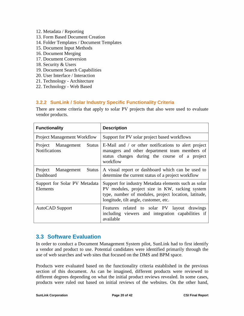
3.2.2 SunLink / Solar Industry Specific Functionality Criteria
There are some criteria that apply to solar PV projects that also were used to evaluate
vendor products.
Functionality Description
Project Management Workflow Support for PV solar project based workflows
Project Management Status
Notifications
E-Mail and / or other notifications to alert project
managers and other department team members of
status changes during the course of a project
workflow
Project Management Status
Dashboard
A visual report or dashboard which can be used to
determine the current status of a project workflow
Support for Solar PV Metadata
Elements
Support for industry Metadata elements such as solar
PV modules, project size in KW, racking system
type, number of modules, project location, latitude,
longitude, tilt angle, customer, etc.
AutoCAD Support Features related to solar PV layout drawings
including viewers and integration capabilities if
available
3.3 Software Evaluation
In order to conduct a Document Management System pilot, SunLink had to first identify
a vendor and product to use. Potential candidates were identified primarily through the
use of web searches and web sites that focused on the DMS and BPM space.
Products were evaluated based on the functionality criteria established in the previous
section of this document. As can be imagined, different products were reviewed to
different degrees depending on what the initial product reviews revealed. In some cases,
products were ruled out based on initial reviews of the websites. On the other hand,
SunLink Corporation Page 21 of 42 CSI Final Report
multiple conversations and multiple demos were provided to the pilot team for products
that seemed to meet the majority of the criteria. Finally, in some cases such as for
OpenText and Pervasive, the sheer cost of the products eliminated them from contention.
3.4 Software Selection
After an extensive review of several DMS vendors, SunLink determined the M-Files
product was best suited for our business model, business size, and industry segment.
3.4.1 M-Files DMS Overview
M-Files Corporation is a Microsoft Gold Independent Software Vendor (ISV) Partner and
an Autodesk Authorized Developer. The latter is a big plus for solar PV companies like
SunLink which rely on AutoCAD for layouts and drawings.
The M-Files DMS also includes a .NET API which can be used to integrate with external
systems such as a CRM. Alternatively, ODBC can also be used as an integration method
for data lookups. SunLink used ODBC integrations to look up metadata values from its
ERP. It is worth noting the M-Files architecture can be deployed as a cloud, enterprise, or
hybrid solution.
For additional information, please refer to the M-Files website: http://www.m-files.com
3.5 SunLink Pilot
In order to determine the benefits and/or drawbacks to the use of a DMS for a solar PV
BOS provider such as SunLink, a pilot of the selected DMS was performed. The pilot
consisted of processing a number of projects through the DMS workflow and using the
features of the DMS to simulate a real life production environment.
3.5.1 Detail Pilot Scope
To keep the scope of the project manageable from a resource and time perspective, the
following boundaries were established:
1. Roof mount systems only
2. Starting point is creation of new project based on customer quote request
3. End point is the customer acceptance or rejection of a contract (should a project reach
this point in the process)
4. Integrations in scope include CRM integration and ERP ODBC lookups. All other
potential integrations were out of scope for the pilot and were performed manually
5. Customer interactions with the workflow were simulated by Sales personnel
6. A small team was assembled to carry out the pilot.
SunLink Corporation Page 22 of 42 CSI Final Report
3.5.2 Pilot Team & Departments
Based on the established scope, the pilot participants included the following departments:
Sales, Layout, Project Management, Engineering, IT, Operations, and Management. The
Pilot team was responsible for establishing the pilot requirements, DMS configuration
requirements, processing projects and documents in the DMS, and providing feedback for
the DMS activities.
3.5.3 Pilot Workshops
In order to establish the detailed process requirements and configuration needs for the
pilot, two separate workshop sessions were held with the Pilot Team. The majority of
work revolved around the design of the project based workflow. The workflow consisted
of a typical solar industry BOS provider process of creating a project for a particular solar
installation through having a customer approve the business contract for the solar
racking.
3.5.4 Pilot Workshop Deliverables
Pilot Workshops yielded two documents. The first document was a detailed flow chart
showing the process steps and logic for the new project through customer contract
approval. The second document was a detailed matrix identifying each process step in the
workflow document and specifying its requirements in terms of metadata to be gathered,
possible next steps, required documents, and other specifics about the process step. These
two documents were used as the primary references for configuring the DMS
environment.
3.5.5 Pilot DMS Environment Configuration
Before a DMS can be used to process projects and documents, it must be configured. For
the purposes of the pilot, the M-Files document vault, (DMS repository), was hosted on
the cloud. This eliminated IT administration and infrastructure concerns associated with
an enterprise deployment. The following sections detail aspects of the DMS that required
configuration in preparation for the pilot. As the pilot progressed, the configuration and
setup of the DMS was fine-tuned based on user feedback. The Information Technology
Department pilot participants were granted administrator privileges to access and
configure the DMS environment. Once the M-Files Client and Vault connection were
established, a user could access the M-Files application and begin using the DMS.
3.5.6 User Configuration
M-Files, like the majority of its peers, requires named user accounts in order to track
activity in the system and assign permissions for the various features available in the
software. As part of the configuration setup, users, user groups, and permissions on the
objects in the system were established.

SunLink Corporation Page 23 of 42 CSI Final Report
Each pilot participant was provided with a user account to use the DMS. Permissions
were configured for users based on User Group (Sales, Layout, Structural Engineering,
etc.) or individual user based on the business requirements.
3.5.7 Workflow Configuration
For Solar PV BOS providers and other project-based companies, workflow definition is
one of the most time consuming and important configuration items in the DMS. Based on
the findings of the pilot workshops, a workflow for roof mount systems was created.
The workflow definition includes specifying the order in which process steps occur,
determining branches and paths between steps, configuring assignments and notifications
for process participants, and establishing permissions for each step. Essentially, the
configuration of the Project Workflow determines how project process steps will be
executed and how well the model mimics the real life business process flow.
3.5.8 Document Configuration
As part of the DMS configuration, Document Types need to be established. This is true
both so that that different types of documents can be associated with different metadata
elements and to improve efficiency of searches by searching for a particular document
type. Finally, documents exist in a variety of formats and some are created using
templates.
For the purposes of the pilot, a number of documents typically found as part of solar PV
sector business processes were defined.
Some of the document types established for the pilot include:
1. AutoCAD Layout
2. Sales Contract
3. Customer Module Spec Sheet
4. Building Drawings
5. Customer Contributions
6. Engineering SAP & MATLAB Files
7. Budgetary Estimate
8. Email
9. Final Wind Load Report
3.5.9 Metadata Configuration
Metadata are data elements that can be associated with different objects in the system.
They represent a powerful concept in DMS systems as these data elements can be used
for a number of purposes including reporting, automatically taking action on objects
based on metadata values (such as workflow steps), and searches. For the pilot, metadata
elements were defined for projects and for documents. The defined metadata elements,
not surprisingly, reflect data elements required in Solar PV projects.
SunLink Corporation Page 24 of 42 CSI Final Report
3.5.10 Views
Views are flexible tables within the M-Files system for viewing data. While different
from reports, these grids allow users to display data pertinent to their needs through the
use of data filters and selected data columns.
3.5.11 Reports
One of the powerful features of the M-Files DMS is reporting on metadata values. As
part of the pilot, SunLink had M-Files create a few reports based on Pilot Team
recommendations as made during the Pilot Workshops. In addition to tabular reports, M-
Files also supports charts and other graphical report types.
3.5.12 Pilot Execution
After the configuration of the DMS vault, M-Files conducted a two hour training class on
the use of the DMS. The training covered the standard system feature set and provided a
general overview on working with project workflows.
After the M-Files training, several mock solar PV projects were created to test the
workflow configuration and train the Pilot Team users on the solar PV specific workflow
created in M-Files based on the Pilot Workshop. This internal training familiarized each
of the Pilot Team’s members with each of their responsibilities during the project
workflow.
Once the Pilot Team had processed the mock projects and felt comfortable working in the
system, real solar PV projects were selected for the team to process in M-Files while in
parallel performing the standard process (without the DMS). In order to mitigate risk of
impacting live projects, a test environment of the SugarCRM was used. This completely
isolated the existing live process from the DMS pilot environment.
During the course of the pilot, the Pilot Team provided feedback to IT personnel. As the
Pilot Team familiarized itself with the DMS and the project workflow, changes were
requested to improve functionality, improve efficiency, and provide more capabilities for
the users that yielded additional benefits of the system. For example, standard naming
conventions established at the beginning of the project were modified to provide
additional flexibility, and new views were created for users to more efficiently view the
information required by their departments.
3.6 Pilot Outcome / Results
The following sections summarize the findings of the Pilot Team.
SunLink Corporation Page 25 of 42 CSI Final Report
3.6.1 Pilot Team Feedback
At the conclusion of the pilot, team members were surveyed to evaluate the impact of the
DMS. Of the team members polled, all were found to be in favor of deploying a DMS
permanently. More than 80 percent of respondents were strongly in favor of this position.
This is a strong indicator that the benefits of the DMS were significant to their work.
Regarding efficiency, all respondents to the survey indicated they had seen an
improvement in productivity. Half the respondents indicated the use of a DMS was
somewhat more efficient than the existing process. The other half found the DMS to
provide significant gains in productivity.
Based on the survey results, we conclude the DMS provides work efficiencies and
sufficient benefits that users would be in favor of using one permanently in the
organization.
3.6.2 Benefits of a Structured DMS
The following benefits identified during the DMS pilot program are extensible to other
firms in the solar industry if they follow similar DMS implementation programs:
1. Standardization of processes through the workflow functionality.
2. Enforcement of process rules and metadata entry through workflow constraints.
3. Improved ease of use and administration through the cloud.
4. Standardization of file naming conventions and file versioning, and elimination of
duplicate documents.
5. Organizational improvement through archive functionality.
6. Provision through Data and Views of better ways to manage information and tailor
data to users’ needs.
7. Improvement of resource and deadline management through workflow and metadata
functionality.
8. Ability to roll back to a previous version of a document.
9. Provision through Metadata reporting of process insights previously unavailable.
10. Creation and tracking within the system of task assignments.
11. Ease searching and locating documents and objects.
12. Ability to control access permissions down to the document level.
13. Ability to share documents with external parties using web portal.
3.6.3 Lessons Learned
Piloting the DMS on the cloud was definitely the right approach. While not all vendors
offer this option, this proved a very efficient way to conduct the pilot. Using a cloud
instance eliminated the need for IT administration and setup of DMS-related hardware
and software. In addition, there were no significant up-front costs as would have been the
case with an enterprise deployment. Finally, a cloud approach made accessing the DMS
simple, requiring only a connection to the internet. Firewall and networking challenges
were avoided. However, the cloud does potentially pose problems related to integration

SunLink Corporation Page 26 of 42 CSI Final Report
with systems within the company’s enterprise. This needs to be evaluated on a case by
case basis.
While gathering requirements and details up front for the configuration of a DMS is
valuable, expect changes once a pilot is underway. A pilot team should allot plenty of
time for making changes to the model and testing the changes during the course of the
pilot.
3.7 Conclusions regarding DMS in Solar Industry
The pilot demonstrated that the use of a DMS can benefit solar PV companies by
enabling better efficiencies, improved quality, and process standardization.
Of the features provided by the DMS, the project workflow and management functions
(such as views, notifications, and task assignments) proved extremely valuable. The
traditional document management functions such as document version control and
document searching also provided significant improvements over the current practice of
employing a traditional file server without document management capabilities.
Based on the findings, SunLink plans to pursue a complete deployment of a DMS and
would suggest other solar PV companies to consider investing in one as well.
In summary, the results of the pilot indicate that a DMS can provide quantitative
improvements in solar company worker productivity and work quality, as well as
qualitative improvements. The standard DMS features related to documents provide
advancements over standard file server practices. These include efficient search,
associated metadata, version control, revision history, and security. In addition, workflow
capabilities and reporting, especially related to projects and project management, provide
significant advantages over typical manual processes.

SunLink Corporation Page 27 of 42 CSI Final Report
4 Seismic Testing and Analysis
The solar photovoltaic industry is growing, and a significant portion of new projects
consist of large arrays installed on top of existing buildings with flat or low-slope roofs
such as warehouses, big-box stores, and schools. To minimize cost and maintenance
requirements in these types of installations, building owners and solar installers typically
prefer to use solar panel support systems that do not require penetrating the roof
membrane. However, without specific guidelines in US building codes for solar, design
engineers, plan check engineers and building officials typically refer to requirements for
nonstructural components, which prescribe systems that are positively attached to the
roof structure.
SunLink, through this CSI-funded research that included non-linear computer analysis
and shake table testing, has shown that ballasted, unconnected systems satisfy the life
safety-based intent of the structural code. By demonstrating acceptable performance,
SunLink conforms to the requirements of both the 2009 International Building Code (ICC
2009) and ASCE 7-05 (ASCE 2006) for permitting alternative design methods. This
supports SunLink’s and CSI’s goal of increasing solar penetration in markets previously
deemed unsuitable for roof mounted PV systems.
4.1 Project Approach
SunLink’s objectives in executing full-scale shake table tests of unconnected roof mount
PV systems were as follows:
1. To develop a set of roof motions that covered a range of seismic intensities
2. To develop a matrix of tests that investigated the behavior of two of SunLink’s rooftop
solar systems and key variables such as roof surfaces, ballast arrangements, and roof
slopes
3. To run a suite of seven earthquake roof motions for the range of test setups, using the
Pacific Earthquake Engineering Research (PEER) shake-table facility
4. To determine seismic displacement demands, array component forces and
deformations, and their relationship to ground motions
5. To validate computer models and show that ballasted, unconnected systems satisfy all
code-based life safety criteria, thereby facilitating acceptance of a simpler, less
expensive design
4.1.1 Experimental Roof Motions
In order to accommodate the limited displacement capacity of the PEER table, the
SunLink research team, including partner Rutherford & Chekene, filtered and spectral-
matched earthquake motions recorded at two California locations during two different
earthquakes. The resulting experimental roof motions are conservative in terms of
determining seismic design displacement designs, sliding amplitudes, and orbits of the
unattached solar arrays, such that the nonlinear computer analysis models can be
validated and calibrated.
SunLink Corporation Page 28 of 42 CSI Final Report
4.1.2 Matrix of Tests
Unattached rooftop solar arrays are typically installed in a broad range of conditions
related to the type and condition of the roof. To investigate the range of parameters
deemed likely to affect the response and the sliding behavior of the unattached solar
arrays, the SunLink research team conducted earthquake tests on combinations of the
following key parameters:
1. Array system (Core RMS and Precision RMS)
2. Roof surface (PVC and mineral cap sheet)
3. Heavy and light ballast
4. Wet and dry surface
5. Flat and slightly inclined roofs
4.1.3 Execution of Tests
SunLink’s Precision RMS and Core RMS roof mounted PV systems were analyzed in
full-scale tests at the PEER shake table. Because roof mount systems are typically
installed on a variety of roofing materials, each with a different coefficient of friction, the
SunLink team constructed two unique roof structures. One 18x25 foot timber-framed
roof was surfaced with a mineral cap sheet (MCS) membrane and the other with a
polyvinyl chloride (PVC) membrane to represent the range of possible coefficients of
friction. Each roof was installed on a subassembly steel frame and tilted to the
appropriate angle when it came time for testing. While presenting the research team with
some logistical challenges, this method allowed for the greatest diversity in the test
regimen while maintaining efficiency in the allotted time at the PEER shake table.
Each test setup was subjected to three different three-component roof displacement input-
histories, two of which were high-pass filtered, spectral-matched motions and one of
which was unmodified. For the two filtered roof motions, seismic intensities of SDS =
0.5g, SDS = 1.0G and SDS = 1.5g were tested.
4.1.4 Gathering of Test Data
To record the behavior of the solar array test specimens during the shake table tests, the
research team created instrumentation layouts using ten accelerometers, twelve wire
potentiometers measuring displacement, and two linear variable Novotechnik transducers
measuring displacement across the system diagonals. This instrumentation setup was able
to accommodate both flat and sloped roof condition for both the Precision RMS and Core
RMS models.
4.1.5 Computer Model Validation
From a qualitative perspective, the seismic testing of unattached solar arrays confirmed
our prediction that sliding displacements are negligible in small earthquakes (the ten-year
SunLink Corporation Page 29 of 42 CSI Final Report
event) and manageable in large earthquakes (the thousand-year event). The displacement
values we recorded were within the ranges put forward by the previously-created
computer analysis models, and by further calibrating those models, we anticipate being
able to increase the accuracy of our seismic design of unconnected solar systems.
4.2 Project Outcomes
The full-scale shake table tests of the SunLink roof mount PV systems provided the data
necessary for validating and optimizing computer analysis models of friction-based
unattached arrays. Once the computer models are confirmed as accurate, these models
can then predict the displacement behavior of SunLink systems in any seismic
environment.
4.3 Conclusion
The shake table tests clearly demonstrate that friction limits the sliding displacement that
solar arrays experience when subjected to design-level and maximum-considered
earthquakes. For systems on low-slope roofs (0 to 7 degree slopes), designers can
accommodate these seismic displacement demands by providing adequate displacement
capacity for electrical wiring and components. We found that design seismic
displacements tend to increase with higher site seismicity, lower coefficients of friction,
and steeper roof slopes. Therefore, it is important that designers accurately capture the
anticipated seismicity of a project location and the maximum roof slope on which a PV
system is installed. It is also essential to perform full-scale friction testing of the interface
between the solar array and the roof membrane.
4.4 Recommendations
Moving forward, the solar industry in California will continue to benefit from additional
seismic testing of unattached PV arrays. Additionally, continued dissemination of the
research results obtained during the course of this grant will help move building officials
and plan check engineers toward a better understanding of the behavior of solar arrays
during earthquakes.
4.5 Public Benefits to California
Unattached PV systems allow for greater solar penetration due to decreased system and
installation costs, as well as allowing PV to be installed on structures unsuitable for
mechanical connections through the roof membrane. By confirming that solar arrays can
and should be designed as friction elements interacting with the roof surface during
seismic events, this research facilitates the conversation towards permitting unattached
systems in regions of high seismicity.
SunLink Corporation Page 30 of 42 CSI Final Report
5 Database – California Agency Permit Document Requirements Database
In addition to providing customized module mounting systems and other balance of
system (BOS) components for photovoltaic (PV) arrays, SunLink also provides essential
documents used for the permitting and constructing of these arrays. These documents
must be accurate, integrated, and consistent for use by the customer, other consultants,
and permitting agencies. Thus, access to the engineering parameters and permitting
requirements to create these documents is necessary for SunLink’s ability to deploy
projects and achieve solar energy market penetration goals.
An impediment to creating and providing accurate engineering documentation for the
engineering, permitting, and construction of SunLink projects is the fact that permitting
agency requirements for projects vary so widely. Each may amend the building code to
tailor it to specific geographical requirements. There is no central source of information
that clearly defines these agency-specific requirements for PV arrays, nor does a set of
solar project engineering guidelines exist for low slope rooftop projects. This lack of
transparency and uniformity can make numerous engineering revisions necessary, creates
delays, and adds cost to the permitting of solar projects in California.
Based upon SunLink experience in permitting projects in California, SunLink determined
that a web-accessible database application incorporating specific data parameters
necessary for the engineering of solar projects would improve the efficiency of the
permitting process. In order to create such a database, the following tasks were
performed:
1. A set of engineering, permitting, and contact information parameters commonly used
through the life cycle of a solar design project was defined.
2. The parameters were organized into a user-friendly database architecture.
3. A number of software platforms were evaluated for their ability to store agency
information, accommodate frequent additions and changes to the database, and allow
for ease of data lookup functionality.
4. In order to allow for the greatest flexibility in user access and future deployment to the
greater California solar community, Django, an open source web application
framework which was originally created to manage database-driven websites, was
selected. The MySQL database, an open source database on which Django can run,
was chosen.
6. An HTML user interface that mirrors the design of the Go Solar California website
was created.
7. Initial data, based on SunLink’s experience in various geographical markets in
California, was added to the database.
8. Testing was initiated within the SunLink engineering group.
SunLink Corporation Page 31 of 42 CSI Final Report
5.1 California Agency Web Application Project Overview
5.1.1 Purpose and Goals
The intent of the California Agency Web Application is to reduce the time and cost of
permitting a solar project by improving the access to necessary technical information. By
developing a web portal for gathering permitting data, the solar industry in California will
benefit in the following ways:
1. Reduce the time and effort required in gathering engineering requirements for solar in
a particular geographical area.
2. Improve communication between building owners, solar installers, engineers, racking
manufacturers, and permitting departments.
3. Encourage future universal code requirements for the installation of solar in
California.
5.1.2 Challenges
Due to the myriad of California building departments, gathering technical information
and ensuring it is current for every community in California poses a challenge. SunLink
has developed an initial database of permitting requirements in California by starting with
its history of California projects, and adding many more, but the success of a public web
application will depend on the participation of the California solar community in
expanding the database and maintaining its accuracy.
5.1.3 Platform
The Django framework allows for flexibility in the creation, maintenance, and future
modifications of the California Agency Web Application. It was chosen to provide the
greatest number of users the greatest ease in user experience while simultaneously
allowing for maximum participation in data collection and maintenance by the solar
community in California. In order to achieve this goal, each user type can access different
levels of the web application. As a user navigates through the levels of the web
application to which they have access, they will be presented with a new user interface
design and variable levels of control over the web application database.
5.2 California Agency Web Application Functionality
Anyone with interest in California solar would have the ability to search for a California
community, defined as any town, city, or census-designated place and view the governing
agency’s permitting requirements for that community. The information available depends
on the data loaded into the database, which reinforces the necessity for the California
solar community to expand and maintain the database.
SunLink Corporation Page 32 of 42 CSI Final Report
5.2.1 Search
When the general user first accesses the web application they will be presented with a
search page. The Go Solar California links are included on this search page in order to
allow the solar community access to further solar information.
5.2.2 Community Information
After the user enters the California community for which they are researching California
permitting requirements, a page displays the following information:
• The California community’s governing building agency
• A web link to the community’s webpage
• Whether the community is incorporated or not and the incorporation date (if relevant)
• The community’s county and a hyperlink to the county’s webpage
• The community’s population
5.2.3 Agency Contact
The following tab provides additional agency information for the selected community. It
displays:
• The building agency name
• The building agency address
• The building agency phone number
• The building agency website
5.2.4 Personnel Contact
The next tab for a community’s data is Personnel Contact Information. This page
contains the following information:
• Contact personnel name and title for building agency
• Contact personnel email
• Contact personnel phone number
• Notes regarding additional personnel contact information
5.2.5 Permit Data
The Permit Data Page shows possible information that could be displayed for a given
building agency. This page contains the following:
• Building code website
• Link to specific permitting requirements for solar on roofs
• Link to specific permitting requirements for solar on ground
• Design wind speed
• Exposure category
• Minimum wind pressure
• Link to wind map
SunLink Corporation Page 33 of 42 CSI Final Report
• Information about the agency’s compliance with California Fire Requirements
• Link to electrical permitting requirements
• Link to alternate means and methods permitting
• Information about the agency’s acceptance of ballast-only roof mounted systems
• The design ground snow load
• The design roof snow load
• Link to snow map
• Link to permit maps
• Link to Agency
5.2.6 Documentation and Links
The Documentation and Links Page of the California Agency Web Application, shows
the webpage that will contain any additional documentation and links about solar
permitting in the given community. This page completes the accessible information for
the general public for a given community. From this page, any user could navigate back
to the original search page for information on another community or navigate to the Go
Solar California website.
5.3 Database Login with Administrator Privileges
If a user has login credentials to access the database front-end portion of the site, they
will be able to add, delete, or edit information to which they have administrator
privileges. In addition to the generally available web application pages, the following
administration pages become accessible:
5.3.1 Search
While any general users can search for communities in California, a user with Database
Login Credentials can also add a community to the database. In order to do so, the user
would login to the administration page of the California Agency Web Application,
navigate to the Community page, and click “Add Community Name.” Once a
community name is added, the user must link to a relevant building agency. This
parameter is required. This and any other required data parameters appear in bold print.
5.3.2 Community Information
In addition to linking to a relevant building agency, a user with Database Login
Credentials can also add information to the community he or she creates. This
information will appear on the Community Information Page of the California Agency
Web Application. However, since these fields are not shown in bold print, they are not
required. If these fields have not been completed, a general user will still be able to
search for the new community name, but will see nothing on the corresponding
Community Information Page.
SunLink Corporation Page 34 of 42 CSI Final Report
5.3.3 Agency Contact
Once a community name is added to the database, a user with Database Login
Credentials can log off the administration interface and the changes to the California
community would be saved and stored in the database. However, if the user wishes to
add, edit, or delete information for a California building agency, they must navigate to
the Agency page of the administration interface. From this point, clicking on an agency
name will bring the user to the data interface for that particular agency. There, the agency
information can be edited. Any changes to the agency contact information will appear to
general users who subsequently access the Agency Contact page.
5.3.4 Personnel Contact
If the user with Database Login Credentials continues to navigate down the Agency page,
they will find further data fields to edit the personnel contact information, shown in the
Personnel Contact Information on the Administration Interface.
5.3.5 Permit Data
Permit data can also be edited on the agency page of the administration interface.
Changes to these data fields will be seen on the Permit Data Page of the California Web
Application.
5.3.6 Documentation and Links
Edited documentation and links on the agency page of the administration interface are
shown on the Documentation and Links Page of the California Agency Web Application.
As the California Agency Web Application is currently constructed, all users with
administrative privileges may also add and delete California Agencies. It is recommended
that this setting be reviewed before public launch of the Web Application, particularly if
a large segment of the California solar industry is granted administrative privileges.
5.3.7 Web Application Manager
The manager of the Agency Database web application can add, delete, or edit information
to any community or governing agency, as well as control the application backend, which
includes the specific data set included for each community and agency in California (the
structure of the MySQL database) and the look and feel of the website (HTML and CSS).
The Web Application Managing user group has the ability to code in the Python
computing language in order to maintain and directly edit the Django web interface code.
This includes any schema changes to the database, i.e. eliminating or adding data
parameters.

SunLink Corporation Page 35 of 42 CSI Final Report
The Managing user group would also benefit from an understanding of web design. If the
look of the web application needed to be changed, it could be altered through the Django
HTML scripts.
5.4 California Agency Web Application Development Completed Milestones
Since the initiation of the California Agency Web Application development, the
following milestones have been achieved under the SunLink--CSI grant:
1. The web framework, Django, and the open source database management system,
MySQL, were chosen to implement the California Agency Web Application.
2. Web design using HTML and CSS was completed for two versions of the California
Agency Web Application – one version to match the SunLink web design template,
another to match the Go Solar California web design template.
3. The home page search field of the California Agency Web Application was created
and debugged. In order to find solar permitting information for a California
community, a user must input a California community’s name. However, the name
may be incomplete and lack capitalization while still resulting in a successful search.
In addition, if the string of characters used in the search tool match portions of
multiple California communities, all relevant communities and their data will be
retrieved and displayed on the web application pages.
4. The California Agency Web Application was ported from a development server to a
beta version, deployable server. This transition included numerous code-level
changes to the Django framework.
5. The California Agency Web Application database was filled with preliminary data
from SunLink’s historical California projects.
6. Testing of the web application on various browsers commenced. Small changes were
made to the HTML web design in order to ensure design consistency through all
major web browsers.
7. The California Agency Web Application was released to the engineering team at
SunLink. Users have administrative privileges in order to encourage ongoing data
collection and validation as well as error debugging.
In summary, the California Agency Permit Document Requirements Database provides a
useful tool for California Solar PV Stakeholders to access important information about
agency requirements, specifications, locations, and personnel.
SunLink Corporation Page 36 of 42 CSI Final Report
6 Recommendations
During the course of this development project, SunLink performed tasks in several
defined areas:
Engineering Automation – SLDS Engineering Automation
Process Definition and Automation - Document Management Systems
Full Scale Laboratory Testing - Seismic testing
Organization and Access to Fragmented Information - Permitting Database
There are a number of recommendations that flow from this work. These apply at several
levels, including the firm, the industry and the regulatory environment.
6.1 Engineering Automation
Firms should take full advantage of both automating their engineering processes and
integrating their engineering systems. The development of standards of practice for solar
PV will help PV system suppliers, engineering firms, building owners and permitting
agencies work more effectively together to develop and share information.
Many smaller PV firms have neither the technical resources nor the capital to support a
large scale development effort. SunLink-CSI work in these areas illustrates opportunities
for the development of commercial software packages to support solar PV systems, either
in the form of add-ons to existing engineering platforms, or new software tools for layout,
design, and analysis.
6.2 Process Definition and Automation
California solar PV companies can achieve efficiencies and qualitative benefits through
the use of Document Management Systems (DMS). Solar PV companies interested in
implementing a DMS should strongly consider performing a pilot. Workflow capabilities,
metadata functionalities, and document management features are three areas that our pilot
determined to be key factors of successful DMS implementation. A cloud-based
installation provides an efficient way to support a pilot and provide a gradual and cost
effective entry to DMS deployment.
Developing replicable processes to create and manage engineering deliverables helps
reduce the cycle time and number of cycles required to support permitting activities.
Reducing plan check cycles makes both solar firms and the solar industry more
productive.

SunLink Corporation Page 37 of 42 CSI Final Report
6.3 Full Scale Laboratory Testing
Research testing and analysis of full-scale, ballast-only PV systems in seismic regions
confirms that displacements due to system sliding during an earthquake are predictable.
With the continued dissemination of test results and the evolution of permitting
standards, we expect that unattached PV systems will increasingly be permitted on roofs,
thereby reducing the cost of rooftop solar arrays and increasing market penetration.
Building codes do not yet specifically address the challenges of designing solar PV
arrays. Additional testing can help demonstrate the limits of safe and efficient PV
systems operation. This can help support additional penetration of solar in California by
increasing the inventory of available roof sites.
The research and analysis performed by SunLink and R+C into the performance of
unattached PV systems on roofs in seismic areas was utilized by the Structural Engineers
Association of California Solar Photovoltaic Systems Committee to produce a report
entitled “Structural Seismic Requirements and Commentary for Rooftop Solar
Photovoltaic Arrays.”
The results of testing can be disseminated and implemented much more quickly than the
traditional code revision cycle. The SEAOC Reports that this research helped support are
already being cited by code officials and used as guidelines for permitting solar PV
systems in California.
6.4 Organization and Access to Fragmented Information
The California Agency Permit Document Requirements Database created under this grant
is an important first step in creating a single point of access for information to support the
entire California solar industry. However, any such database must be managed and
continually updated to provide any value to its user community. SunLink recommends
that the initial site be accessed via the Go Solar/CSI site. One feasible method of updating
is to take a Wiki approach whereby members of the California solar community take
responsibility for insuring that the information contained is accurate and up to date. Even
so, the site will still require some minimal amount of oversight to be successful.
This approach could become a model for organizing and sharing other types of solar
information. In particular, there would be clear value in the development of a standard
module database with up-to-date module information supplied and certified by the
module manufacturers and available to all California solar industry participants.

SunLink Corporation Page 38 of 42 CSI Final Report
7 Public Benefits to California
When SunLink and CSI began this project, it was with the explicit goal of increasing
solar penetration in California through improvements in several areas of rooftop system
design, engineering, and implementation.
The two most immediate and broadly useful SunLink outputs from this effort are 1) the
permitting official database, and 2) the near-term direct impact of the seismic testing on
code setting for unattached arrays.
Additional public benefit will be garnered over time as the benefits of the engineering
automation and document standardization work become widely known and implemented
by other solar design firms and permitting agencies.
7.1 California Agency Permit Document Requirements Database
The permitting agency database was initially promised as an application with 10 entries.
It was envisioned as a structure, but a nearly-empty one. As delivered, there are 1579
community entries covering all 58 California counties. This is a credible and useful start
to what will become a central source of permitting and agency contact data for
individuals and solar installation companies alike. When the database is integrated into
the Go Solar website, with which its design is compatible, it will be easy to locate and a
significant timesaver for those who wish to obtain permits for solar systems.
7.2 Building Code Development for Unattached Solar Arrays
Ballasted, unattached photovoltaic systems are less expensive to install and maintain than
connected systems. They have not, however, had a clear path to acceptance in all
permitting agencies, and were not addressed by standard building codes. The work
performed under this grant has contributed importantly to efforts to incorporate into
building codes sections specifically relevant to the wind and seismic characteristics of PV
systems.
The seismic testing funded at PEER by this grant was essential to SEAOC in the design
recommendations in their report “Structural Seismic Requirements and Commentary for
Rooftop Solar Photovoltaic Arrays,” which can be conveyed to the ASCE 7 committee on
seismic of building components for possible inclusion in building codes. This is
significant because unattached systems enhance building owner acceptance of solar, as
building owners are often reluctant to install penetrating attachments through their roof
membranes.
In addition to seismic testing, the dynamic wind analysis work funded under this grant is
referenced in the SEAOC report "Wind Design for Low-Profile Solar Photovoltaic
Arrays on Flat Roofs." This report proposes changes to ASCE 7-10.

SunLink Corporation Page 39 of 42 CSI Final Report
SunLink has contributed to the safety and efficiency of installation of commercial rooftop
PV in California by providing basic data and analysis essential for improvements in
building codes. Better treatment of PV in standard building codes will result in a simpler
and more uniform permitting process for all rooftop solar. Unattached rooftop PV
systems, with their lower cost and lower risk compared to attached systems, are explicitly
treated in the proposed code modifications for the first time. Owing to the decreased cost
and risk of unattached systems, the SunLink-CSI seismic test results will ultimately help
to lower average costs for rooftop solar and facilitate meeting the solar penetration goals
of the California Renewables Standard.
7.3 Standardization of Permitting Packages
The recent SunLink pilot of a DMS has shown the potential of standardization of
documents to improve the design and delivery of rooftop PV systems. As standard
building codes for PV mature and are widely adopted, it will be possible also to
standardize submittals for building permits. This will have a cost benefit that will be
another factor helping to lower the cost of solar photovoltaic power in California.
7.4 Benefits to the Solar Industry
Lowering the cost of rooftop solar installations enhances the marketability of solar,
increases the number of building owners who may opt for installation, and thus helps
toward achieving the Renewables Portfolio Standard of 33 percent of generation in the
State of California by the year 2020. Cost savings will arise from both the automation of
systems design following the SLDS model, and from the efficiencies and quality
improvements available through the implementation of the DMS. The roadmaps provided
in SunLink deliverables for these two broad areas will facilitate the process for other
solar companies in the state.

SunLink Corporation Page 40 of 42 CSI Final Report
8 Conclusions
SunLink appreciates the opportunity to have performed extensive RD&D work under the
CSI program. This research project has demonstrated opportunities for numerous benefits
to the California solar industry, and has created a roadmap that others can follow to
realize similar benefits in their firms.
These benefits include:
Demonstrated efficiencies of engineering automation
Better work products due to improved process definition and systems integration
Improved information sharing and a more efficient permitting process
Efficient portal-based access to public information
Opportunities for further work to improve PV solar implementation in California
Finally, this work has demonstrated the value of the public-private partnership approach
that can help move the solar industry towards more automated and efficient delivery of
roof mounted projects.
SunLink Corporation Page 41 of 42 CSI Final Report
9 Technology Transfer – Research Project Knowledge Sharing
Trade Journals and Press Carlsen, R. “U.C. Berkeley’s PEER Center Hosts Shake Test for Alternative Solar
Racking System,”
Engineering News-Record, March 19, 2012
Riddell, L., “SunLink studies seismic effects on solar,” San Francisco Business Times,
March 6, 2012
Ward, R., Miller, K., “Ballasted Solar Systems in High Seismic Areas,” Solar Novus, 24
October 2012
Technical Conferences
Holland, R.H., Miller, K., and Schellenberg, A. “Approach to Parametric Analysis of
Wind Load Effects on PV Solar Roof Bearing Arrays Using OpenSees” PEER OpenSees
Days presentation, 16 August 2012.
Schellenberg, A., Fathali, S., Maffei, J., Miller, K., “Seismic Behavior of Unattached
Solar Arrays on Flat Roofs: Analysis, Shake Table Testing, and Proposed Requirements,”
Proceedings Structural Engineers Association of California / Structural Engineers
Association of New Mexico Convention, Santa Fe, NM September 2012.
Tilley, C., “Accelerating BOS Cost Reduction through Integration,” 4th
PV Power Plants
Conference, Phoenix, AZ, November, 2012
Williams, J. M., “Engineering Challenges for Photovoltaic Power Systems,“ 2nd
International Conference for Sustainable Design, Engineering and Construction, Fort
Worth, TX, November 2012.
Maffei, J., Fathali, S., Telleen, K., Ward, R., and Schellenberg, A. (2012). “Seismic
Design of Ballasted Solar Arrays on Low-Slope Roofs.” Submitted to J. Struct. Eng.
Schellenberg, A., Maffei, J., Miller, K., Williams, M., Ward, R., and Dent, M. (2012a).
“Shake-table Testing of Unattached Rooftop Solar Arrays: Final Report, Subtask 4.2.”
SunLink/Rutherford & Chekene report for the California Solar Initiative
www.gosolarcalifornia.org/csi
Schellenberg, A., Fathali, S., Maffei, J., Miller, K. (2012b) “Seismic Behavior of
Unattached Solar Arrays on Flat Roofs: Analysis, Shake Table Testing, and Proposed
Requirements.” SEAOC 2012 Convention Proceedings.
SunLink Corporation Page 42 of 42 CSI Final Report
Trade Shows Tilley, C., “Standardization of Codes for Solar Project Development,” Solar Power
International Orlando, FL, September 2012
SunLink White Papers SunLink Seismic Testing Roof Integrity Report
SunLink Webinars Miller, K., Ward, R., ”Designing for Earthquakes: Lessons from SunLink’s Full-Scale
Shaking Table Experiments,” September 25, 2012
CSI Final Webinar December 18, 2012 – Itron Oakland offices
Peer Reviewed Journals
Maffei, J., Fathali, S., Telleen, K., Ward, R., and Schellenberg, A. (2012). “Seismic
Design of Ballasted Solar Arrays on Low-Slope Roofs.” Submitted to ASCE Journal of
Structural Engineering, 2012
Technical Committees Structural Engineers Association of California Solar Photovoltaic Systems Committee,
“Structural Seismic Requirements and Commentary for Rooftop Solar Photovoltaic
Arrays” SEAOC PV1-2012 August 2012.
Structural Engineers Association of California Solar Photovoltaic Systems Committee,
“Wind Design for Low-Profile Solar Photovoltaic Arrays on Flat Roofs” SEAOC PV2-
2012 August 2012.
University Lectures Mike Williams – Stanford University – Civil and Environmental Engineering – Spring
2011 and Spring 2012
Mike Williams – UC Berkeley – Civil Engineering – Fall 2011