final project report - bureau of safety and … products constitute endorsement or recommendation...
TRANSCRIPT

1
Final Project Report
Project Title: Temporary Oil Spill Storage and Recovery in Alaskan Arctic
Environments Using New PETROGELTM Technology
Principle Investigator: Professor T. C. Mike Chung
Department of Materials Science and Engineering
The Pennsylvania State University
University Park, PA 16802
Email: [email protected]
Disclaimer This final report has been reviewed by the BSEE. Review does not signify that the contents necessarily reflect the views and policies of the BSEE, nor does mention of the trade names or commercial products constitute endorsement or recommendation for use. Acknowledgements This study was funded by the Bureau of Safety and Environmental Enforcement (BSEE), U.S. Department of the Interior, Washington, D.C., under Contract E14PC00002.
2
Executive Summary: In this R&D project, we have completed a comprehensive study to investigate i-Petrogel
oil superabsorbent polymer (oil-SAP) for oil spill recovery of ANS oil in Alaskan Arctic seawater conditions. The project was divided into two periods, including Base Period (between September 15, 2014 and November 30, 2015) and Option Period (between December 1, 2015 and March 31, 2017), and a Go/No-Go decision between them. The study was geared to answer several key questions in i-Petrogel oil-SAP material, including the absorption capacity and kinetics, the prevention of spill oil from weathering (evaporation, emulsification, spreading, etc.), the recovery and transport of the absorbed oil, and the reuse of the recovered oil. In addition, we have also developed the large-scale and economic material production process.
In the Base Period, two major tasks were successfully executed. Task 1 focused on the development of a suitable Petrogel material (named i-Petrogel) with an inter-penetrated network (IPN) between interlaced rigid and soft polymer chains. This new i-Petrogel structure can effectively absorb ANS oil that has a complex mixture of hydrocarbons. After validating its oil absorption performance in the Penn State laboratory, we performed a scale-up study to prepare i-Petrogel with pounds-quantity and to understand the large-scale production process. In Task 2, we successfully prepared >20 pounds of Petrogel material in flake form, with two compositions of 1/1 and 3/1 rigid/soft polymer weight ratios (>10 pounds each). BSEE conducted an operational test on these two i-Petrogel samples in a fast tank at the Ohmsett facility. The test verified the effectiveness of the i-Petrogel absorbents with ANS oil with the absorption capacity 30-40 times and fast kinetics, recovery of the resulting oil/i-Petrogel on the water surface by skimmers, and the pumping ability of the resulting oil/i-Petrogel adducts.
In Option Period (after a Go-decision), the major task was to manufacture 250 pounds of i-Petrogel for BSEE to conduct a simulated field test in the Ohmsett facility. We installed a pilot plant facility at Penn State and improved the production process with significant cost savings and other advantages. We completed the delivery of 250 lbs i-Petrogel flakes before the simulation test which occurred the week of December 19-22, 2016. The test was conducted in the main tank under various operational conditions, simulating the conditions that i-Petrogel might encounter in the Arctic environment. The objective was to evaluate its oil absorption properties and the ability to be recovered by mechanical means (using oilophilic drum skimmer).
This report summarizes some important results. Overall, we have successfully conducted all proposed R&D tasks and achieved the milestones proposed for the project. The performance testing results in Ohmsett were encouraging. The i-Petrogel flake, with a 1/1 rigid/soft polymer weight ratio, is capable of absorbing ANS oil about 40 time its weight with certain contacting time. The resulting ANS oil/i-Petrogel viscous fluid, floating on the water surface, can be effectively recovered by a drum skimmer and pumped to storage vessels. The water content in this recovered ANS oil/i-Petrogel fluid, ranging from 0 to 3 wt%, is dependent on drum rotation speed. After the recovered ANS oil/i-Petrogel fluid sat for a few days, most of the picked up water was spontaneously phase-separated and removed. The dry ANS oil/i-Petrogel fluid can be refined as ANS crude oil using a regular distillation process. Overall, this new Petrogel technology offers a combination of benefits in oil spill response, including (i) high oil absorption capability, (ii) prevention of oil weathering, (iii) easy recovery from water surface, (iv) no water absorption, (v) the recovered oil treated as regular crude oil for refinery, (vi) no waste in natural resources and no air/water pollutions, and (vii) cost effective and economically feasible.
3
I. Background: I-1. Current Methods for Combating Oil Spills
The negative environmental and economic ramification of oil spills have been the subject of constant debate and a painful reminder of our dependence on oil for energy and chemical resources. Yet, there is still some significant technology gap for dealing with inevitable and unpredictable oil spill. Three methods, booms and skimmers, dispersants, and controlled burning, are commonly deployed to combat an oil spill on the open seas. In the 2010 BP Deepwater Horizon oil spill in the Gulf of Mexico, the decision to use 2 million gallons of dispersants1 in the Gulf amounted to an environmental trade-off with the long-term concern below the surface. Based on estimation , the majority of BP oil spilled was wasted and conceded as pollutants. Only about 10% of the spilled oil was removed by mechanical recovery. The recovered oil itself generated about 40,000 tons of solid waste due to soiled booms and more than 7.7 million gallons of oily liquid waste (mixed with water).2,3
When an oil spill occurs on water, the first few hours of actions are most critical in determining the effectiveness of later recovery, removal, and disposal, as well as the level of environmental impact. In addition to minimizing danger and potential damage to persons, property, and natural resources, the immediate protocol shall restrict the spread of oil and prevent the evaporation of light hydrocarbons and emulsification with water as soon as possible. Currently, the most common first action is the deployment of floating booms. With some pre-position effort, they can be deployed in the relatively short time. However, they cannot prevent the evaporation of lighter or more volatile hydrocarbons within the oil mixture, nor emulsification to form small oil/water droplets to hamper recovery and cleanup process. Furthermore, the efficiency of both skimmers and booms are very dependent on weather conditions. While most booms perform well in gentle seas, the forces exerted by currents, waves, and wind may impair the ability of a boom to hold oil. In choppy water, skimmers tend to recover more water than oil. The presence of ice in Alaska environments may further complicate the recovery operation.
Sorbents have been applied in oil recovery (and have the potential for oil storage). Currently, they are most often used to remove final traces of oil, or in areas that cannot be reached by skimmers. After recovering oil, they are removed from the water and often disposed of. Sorbents can be divided into three basic categories: natural organic, natural inorganic, and man-made synthetic polymer. Due to economic and environmental (bio-degradability) concerns, the most common sorption materials used are natural organics (straw, hull, corncob, peat moss, sugarcane bagasse, wood/cotton fibers, wool-based materials, silkworm cocoon waste, etc.)4-10 and natural inorganics (i.e. clay, talc, zeolites, silica aerogel, calcium fly ash, etc.).11,12 However, most of them show limited oil sorption capacity and also absorb water, thus making the recovered solids unsuitable for calcinations; most of them end up in the landfills. In synthetic polymer sorbents, melt blown polypropylene (PP) pads and booms13,14 are the most commonly used oil sorbent materials, which can be cleaned and reused several times. However, due to the weak oil-substrate interaction (adsorption mechanism), the fiber-based adsorbers exhibit many disadvantages, including failure to maintain oil of low viscosity and easy re-bleeding of adsorbed oil under a slight external force. Overall, it is still a major scientific challenge to identify a suitable oil sorption material, and the treatment of the recovered solid materials is always a major concern, including waste disposal, recyclability, and biodegradability.

4
I-2. Petrogel Absorbent Technology (prior to this project): In light of the 2010 BP mass oil spill in the Gulf of Mexico and the lack of effective
technology for preventing such an environmental disaster, we started a research challenge with an idea of developing an oil super-absorbent polymer (oil-SAP) that can rapidly transform a maritime oil spill into a floating solid (an oil-swelled gel without any water) that can prevent oil weathering and is ready for collection (recovery) by skimmer. In addition, the recovered oil-swelled gel can be refined as regular crude oil, preventing the needless wasting of this natural resource and rectifying issues surrounding solid wastes disposal and pollution.
The most common and inexpensive oilphilic polymers are polyolefin polymers, including polyethylene and polypropylene. As discussed, the melt blown PP pads and booms are used in small-scale spilled oil cleanup. Due to high crystallinity, these polyolefin sorbents primarily exhibit an adsorption (not absorption) mechanism with a limited oil sorption capacity (<10 times of the polymer weight) and easy re-bleeding. Several years ago (prior to this project), we reported a new polyolefin absorbent based on cross-linked 1-octene/styrene/divinylbenzene terpolymer (x-OS-DVB)15-17 with amorphous morphology, which shows a high absorption capacity with low molecular weight hydrocarbons and refined oil products, reaching 40 times that of their weight. In addition, the combination of selective hydrocarbon absorption (without water) and tough mechanical strength offers buoyancy, stability, and easy recovery on water surfaces.
Figure 1. Gasoline up-take for (a) Petrogel and (b) commercial melt blown PP pad. Figure 1 compares the kinetics of oil absorption performance of an Petrogel sample with
a state-of-the-art melt blown PP pad that is fabricated from a nonwoven fibrous PP textile with a highly crystalline polymer structure and porous morphology (high surface area). They were examined side-by-side for comparison. The melt blown PP pads (adsorption mechanism) show rapid oil adsorption in their interstices by capillary action, saturating at 10 times the weight of uptake without any visible volume enlargement. The adsorption mechanism happens only on the PP fiber surfaces (not inside the polymer crystalline matrix), which is advantageous with fast

5
kinetics but with limited capacity, and the weak oil-PP interaction results in some adsorbed oil re-bleeding under a slight external force. On the other hand, the Petrogel sample, with amorphous morphology, gradually absorbs oil in its matrix, increasing its weight and volume by more than 10 times within 10 minutes, and reaching 40 times its weight after 12 hours. Its oil sorption capacity is superior (>4 times) to that of the state-of-the-art melt blown PP pad. Subsequently, the resulting oil/Petrogel (soft gel) floating on the water surface is ready for collection and can be picked up with a tweezer without leaking oil. The absorption mechanism, with the absorbed oil located inside the polymer matrix, is very stable, no oil leaking even after vigorous agitation. In addition, the recovered gels contain no water and are ready for refining as regular crude oil (no waste in natural resources and no disposal issues). This Petrogel is a polyolefin polymer with both aliphatic and aromatic hydrocarbon (monomer) units, which are petroleum downstream products, similar to the major components in crude oils. In addition, the polymer exhibits facile degradation (depolymerization) into monomers (gas and liquid) upon heating beyond 400 oC. In other words, the polymer itself can also serve as part of crude oil components. Furthermore, Petrogel materials (polyolefin products from petroleum downstream) are the most inexpensive polymeric materials, with a large production capability in the United States and around the world. It is scientifically interesting and technological important to further develop this Petrogel technology for absorbing various oils (hydrocarbons), including complex crude oils and viscous lubricant oils.
II. Results from Penn State Laboratory (This Project): II-1. New Design of i-Petrogel Oil Absorbent
Petrogel has been shown to be very effective in absorbing refined oil products, such as toluene, xylene, gasoline, diesel, etc., with relatively low molecular weight and viscosity and narrow composition distribution of hydrocarbon molecules. However, it shows a low absorption capacity and slower kinetics for absorbing large and complex hydrocarbon mixtures, including crude oils. ANS oil contains aliphatic hydrocarbons (65-75%) and aromatic hydrocarbons (15-20%), with the molecular size from C5 to C30, and some impurities. Furthermore, Petrogel is an elastic (soft) material with a low Tg and amorphous (dense) morphology. Due to its soft, somewhat sticky nature, this Petrogel material is difficult to form into thin and small objects, such as powder, foam, flake, or film products, without significant agglomeration. It is clear a strong correlation between the oil diffusion length (shorter is better) and the absorption capacity and kinetics in absorbing complex and viscous oils.
Scheme 1. A schematic representation of the i-Petrogel material with an IPN molecular structure.

6
Thus, in the beginning of this project (Task 1), we redesigned the Petrogel structure from a cross-linked random terpolymer structure to an interpenetrated network (IPN) structure with two cross-linked polyolefin copolymers, as illustrated in Scheme 1. This new Petrogel (now called i-Petrogel) contains two interpenetrated polyolefin chains, one is soft (low Tg) amorphous polymer (elastomer) and one is rigid polymer (either high Tg amorphous or semicrystalline). Two polymer chains are interlaced on a molecular scale. This IPN network cannot be separated unless chemical bonds are broken. The mechanical properties of this polyolefin IPN material can be easily tuned by the mixing ratio between soft and rigid polymers, as well as the DVB (crosslinker) content. As will be discussed, the resulting i-Petrogel material is tough and not sticky and has the mechanical strength to form various structures and morphologies (i.e. films, foams, flakes, powders, etc.). For the operational test at the Ohmsett facility, the cured i-Petrogel films were chopped into flake pieces for easy handling.
As mentioned, an important motivation for developing this i-Petrogel IPN structure is related to the handling of absorbent material. The original Petrogel material, i.e. 1-octene/styrene/DVB random terpolymer, is an elastic (soft) polymer that is difficult to obtain in a stable product form. The soft, somewhat sticky material is usually agglomerated into a chunk material, unless the soft polymer engages in a heavy crosslinking reaction to tighten the network structure. Unfortunately, our experimental and simulation results (discussed later in Section II-4) have also shown that a higher crosslinking density results in lower absorption capacity (swelling ability). On the other hand, this newly designed i-Petrogel, containing separate but connected soft (aliphatic) and rigid (aromatic) networks, provides the needed structural framework from the rigid polymer segments to support the material in desirable shapes and sizes. Overall, the molecule-scale connectivity between soft aliphatic hydrocarbon segments and rigid aromatic hydrocarbon polymer segments with uniform morphology offers many advantages that reflect in various physical properties and material functions discussed later.
It is interesting to note that most of the reported IPN polymers were based on hydrophilic polymers "Hydrogels", prepared by acrylic monomers and the free radical polymerization mechanism.18-21 Hydrogels swelled in aqueous solution have gained much attention due to their biomedical applications. However, it is rare to find corresponding IPN polymers based on olefinic monomers and the transition metal coordination polymerization mechanism (used in our i-Petrogel polymer preparation). There is no reported use of hydrophobic IPN polymers in oil spill recovery applications. We have submitted a US patent application for this technology to protect the intellectual property.
II-2. Oil Absorption Results of Soft Polyolefin Network Before considering the individual soft and rigid polyolefin polymers for i-Petrogel
(Scheme 1), we have to understand the individual polymer structure (i.e. composition, cross-linking density, and morphology) with the oil absorption kinetics and capacity.22 A systematical study was conducted involving several soft and rigid polyolefin copolymers that exhibit a highly swellable network but no dissolution in hydrocarbons at ambient temperature. As shown in Scheme 2, they include a set of cross-linked amorphous poly(1-decene-co-divinylbenzene) (x-D-DVB) elastomers (soft polymers) (A) and a set of semicrystalline poly(ethylene-co-1-octene) LLDPE thermoplastics (rigid polymers) (B). They are currently adopted in the preparation of i-Petrogel oil absorbent (Scheme 1) for the Ohmsett tests. The absorption study involves pure hydrocarbons (toluene and heptane), refined oil products (gasoline and diesel), and Alaska North
7
Slope (ANS) crude oil. In addition, the Flory-Rehner theory is also applied to determine the network structure (i.e. cross-linking density and molecular weight between cross-links) and provide the structure-property relationships.
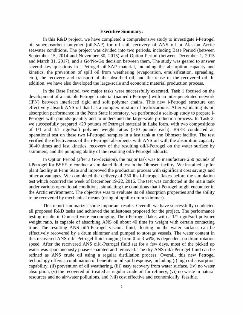
Scheme 2. Two sets of polyolefin structures used in this absorbent study
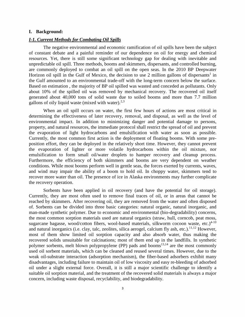
Scheme 3 shows the Ziegler-Natta catalyst mediated 1-decene/DVB copolymerization to form poly(1-decene-co-divinylbenzene) (D-DVB) copolymer with high molecular weight and a uniform copolymer composition. The combination is essential in forming a complete network structure with a very low DVB crosslinker content. In addition, poly(1-decene) is a polymer with high entangle molecular weight and spontaneously forms low density material with high free volume, due to the long side chain in each monomer unit. They are also very beneficial in crosslinking reaction and absorption kinetics (discussed later).
In a typical copolymerization, a specific monomer mixture was introduced into a reactor
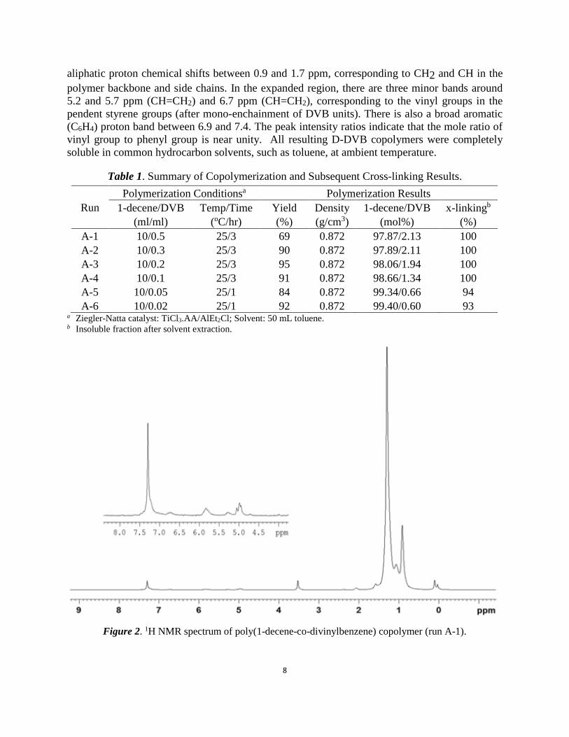
containing Ziegler-Natta catalyst and toluene solvent. The polymerization was carried out under N2 atmosphere with constant agitation. After certain reaction time and a specific reaction temperature, the reaction was terminated by adding isopropanol, then the coagulated polymer was washed, dried, and weighted. All resulting copolymers were examined by 1H NMR and GPC to determine their copolymer compositions and molecular weights. Most of polymers were then thermally cross-linked at 220 oC to form the corresponding network structures (C). Table 1 summarizes the copolymerization conditions and results, as well as the subsequent thermal cross-linking efficiencies based on the gel contents. The traditional Ziegler-Natta catalyst (i.e. TiCl3(AA)/AlCl2Et; AA: activated by aluminum) shows an effective incorporation of 1-decene and mono-enchainment of DVB to form poly(1-decene-co-divinylbenzene) (D-DVB) copolymers (A) with various DVB cross-linker contents and excellent catalyst activity in all copolymerization runs. The GPC curve shows a high molecular weight copolymer (>106 g/mole). Figure 2 shows a typical 1H NMR spectrum of D-DVB copolymer (run A-1). There is a triplet chemical shift centered at 0.8 ppm, corresponding to CH3 in the 1-decene units, and a band of
8
aliphatic proton chemical shifts between 0.9 and 1.7 ppm, corresponding to CH2 and CH in the polymer backbone and side chains. In the expanded region, there are three minor bands around 5.2 and 5.7 ppm (CH=CH2) and 6.7 ppm (CH=CH2), corresponding to the vinyl groups in the pendent styrene groups (after mono-enchainment of DVB units). There is also a broad aromatic (C6H4) proton band between 6.9 and 7.4. The peak intensity ratios indicate that the mole ratio of vinyl group to phenyl group is near unity. All resulting D-DVB copolymers were completely soluble in common hydrocarbon solvents, such as toluene, at ambient temperature.
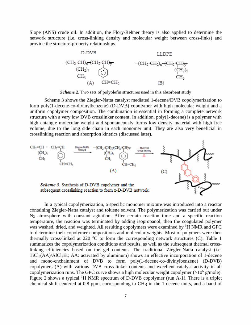
Table 1. Summary of Copolymerization and Subsequent Cross-linking Results.
Run Polymerization Conditionsa Polymerization Results
1-decene/DVB (ml/ml)
Temp/Time (oC/hr)
Yield (%)
Density (g/cm3)
1-decene/DVB (mol%)
x-linkingb (%)
A-1 10/0.5 25/3 69 0.872 97.87/2.13 100 A-2 10/0.3 25/3 90 0.872 97.89/2.11 100 A-3 10/0.2 25/3 95 0.872 98.06/1.94 100 A-4 10/0.1 25/3 91 0.872 98.66/1.34 100 A-5 10/0.05 25/1 84 0.872 99.34/0.66 94 A-6 10/0.02 25/1 92 0.872 99.40/0.60 93
a Ziegler-Natta catalyst: TiCl3.AA/AlEt2Cl; Solvent: 50 mL toluene. b Insoluble fraction after solvent extraction.
Figure 2. 1H NMR spectrum of poly(1-decene-co-divinylbenzene) copolymer (run A-1).
9
The resulting D-DVB elastomers (A) were divided into about 1/4" sized particles and then heated at 220o C under N2 for 2 hours to form the corresponding cross-linked x-D-DVB samples (C). They were subjected to a vigorous solvent extraction by refluxing toluene for 36 hours to examine any soluble fraction that was not fully cross-linked. As shown in Table 1, most samples with >1 mol% DVB content show no detectable soluble fraction, indicating an efficient crosslinking reaction to form the network structure. Two samples (runs A-5 and A-6) with very low crosslinking density show minor weight loss, which may be partially due to the very soft gel particles that cause some fragmentation and loss during the extraction process. Overall, it implies that the thermally-induced Diels-Alder [2+4] cycloaddition reactions23 happened between two pendent styrene units from two adjacent polymer chains under the solid state conditions. The combination of the long entangle molecular weight of poly(1-decene), minimizing the possible intra-chain cycloaddition reactions between two adjacent DVB units in the same D-DVB polymer chain, and the narrow composition distribution and high DVB reactivity shall also increase the crosslinking efficiency and reduce the unreacted DVB units. As will be discussed, we also apply the Flory-Rehner theory to determine the network structures.
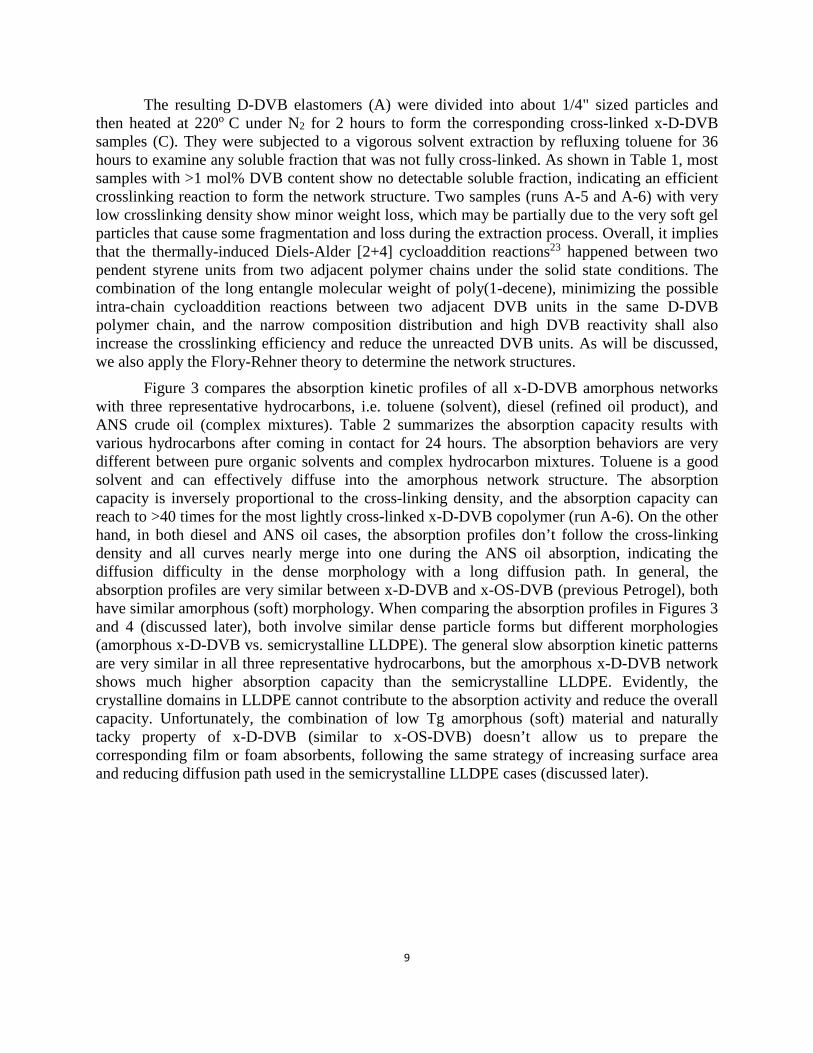
Figure 3 compares the absorption kinetic profiles of all x-D-DVB amorphous networks with three representative hydrocarbons, i.e. toluene (solvent), diesel (refined oil product), and ANS crude oil (complex mixtures). Table 2 summarizes the absorption capacity results with various hydrocarbons after coming in contact for 24 hours. The absorption behaviors are very different between pure organic solvents and complex hydrocarbon mixtures. Toluene is a good solvent and can effectively diffuse into the amorphous network structure. The absorption capacity is inversely proportional to the cross-linking density, and the absorption capacity can reach to >40 times for the most lightly cross-linked x-D-DVB copolymer (run A-6). On the other hand, in both diesel and ANS oil cases, the absorption profiles don’t follow the cross-linking density and all curves nearly merge into one during the ANS oil absorption, indicating the diffusion difficulty in the dense morphology with a long diffusion path. In general, the absorption profiles are very similar between x-D-DVB and x-OS-DVB (previous Petrogel), both have similar amorphous (soft) morphology. When comparing the absorption profiles in Figures 3 and 4 (discussed later), both involve similar dense particle forms but different morphologies (amorphous x-D-DVB vs. semicrystalline LLDPE). The general slow absorption kinetic patterns are very similar in all three representative hydrocarbons, but the amorphous x-D-DVB network shows much higher absorption capacity than the semicrystalline LLDPE. Evidently, the crystalline domains in LLDPE cannot contribute to the absorption activity and reduce the overall capacity. Unfortunately, the combination of low Tg amorphous (soft) material and naturally tacky property of x-D-DVB (similar to x-OS-DVB) doesn’t allow us to prepare the corresponding film or foam absorbents, following the same strategy of increasing surface area and reducing diffusion path used in the semicrystalline LLDPE cases (discussed later).
10
Figure 3. Absorption profiles for six 1-Decene/DVB copolymers with (left) toluene, (middle) diesel, and (right) ANS crude oil.
Table 2. Summary of hydrocarbon absorption capacity of x-D-DVB copolymers.
Run
1-decene/DVB (mol%)
Absorption capacity (weight times)
Toluene Hexane Benzene Gasoline Diesel ANS Oil A-1 97.87/0/2.13 14.9 13.1 12.4 11.8 6.9 9.3 A-2 97.89/0/2.11 20.6 17.7 19.9 18.1 8.8 7.7 A-3 98.06/0/1.94 21.2 19.6 18.6 18.5 8.9 6.7 A-4 98.66/0/1.34 29.8 28.4 22.0 24.8 12.3 7.4 A-5 99.34/0/0.66 32.3 31.7 24.4 25.3 13.2 7.5 A-6 99.40/0/0.60 43.4 34.4 35.2 33.8 12.8 7.5

11
II-3. Oil Absorption Results of Rigid Polyolefin Thermoplastics As discussed, semi-crystalline PE and PP polymers with high crystallinity and a high
melting temperature are not effective hydrocarbon sorbent materials with the adsorption mechanism. So, we chose a series of poly(ethylene-co-1-octene) random copolymers (set B in Scheme 2) with low crystallinity and a low melting temperature. They are commercially-available linear low density polyethylene (LLDPE) thermoplastics with narrow molecular weight and composition distributions, prepared by a homogeneous single-site CGC metallocene catalyst. The 1-octene content in the ethylene/1-octene copolymers is in the range of 4.3 to 9.4 mol%. With the systematical increase of 1-octene (side-chain) content, the copolymer systematically reduces its melting temperature from 106 to 47 oC and crystallinity from 36 to 16%. As the 1-octene content increases, the poly(ethylene-co-1-octene) copolymer becomes soluble in organic solvents at ambient temperature. In addition to the pellet form, these ethylene/1-octene copolymers were also processed into films (thickness=200-300 µm) by solution-casting and melt-compressing processes. They were also converted to foams by a vacuum foaming process to further reduce the copolymer density, which not only increase the specific surface area but also reduce the hydrocarbon diffusion path.
Figure 4 shows the comparative hydrocarbon absorption kinetics of six LLDPE pellets (particle size: 4-5 mm) after coming in contact with toluene, diesel, and ANS crude oil for 24 hours under ambient condition. Table 3 summarizes the final absorption capacities of six LLDPE pellets after 24 hours. Evidently, the absorption capacity of LLDPE pellets with hydrocarbons are relatively small with slow kinetics. After 24 hours, they still do not reach the equilibrium absorption state, even with toluene (a good solvent). However, in each hydrocarbon absorbate case, the absorption capacity of LLDPE consistently shows as inversely proportional to its density, melting temperature, and crystallinity; higher density, melting temperature, and crystallinity lower absorption capacity. The absorption capacity of LLDPE also follows another general trend of toluene>diesel>ANS oil. The refined oil products (toluene and diesel), with low molecular weight (low viscosity) and well-defined compositions, show better absorption capacity. ANS crude oil with a complex hydrocarbon mixture is significantly less effective, with the absorption capacity <3 times that of the polymer weight after 24 hours for all LLDPE copolymers. It is interesting to note that there is a clear divide at about 9 mol% 1-octene comonomer content in this semicrystalline system. The copolymer with less than 9 mol% 1-octene content (Tm >55 oC and crystallinity >16%) absorbs a very small amount of hydrocarbon solvents. The combination of some crystalline domains and dense morphology limits the swelling ability of the polymer, even containing >80% amorphous phase. However, there is a very narrow window in the LLDPE pellet composition (sample B-6), with the lowest melting temperature (47 oC) and crystallinity (12%) before becoming a soluble polymer, which shows a significant hydrocarbon absorption capacity, especially on low molecular weight organic solvents (>17 times on toluene). However, its ANS oil absorption capacity is quite low, about 2.5 times. Overall, the pellet form of LLDPE copolymers are not effective hydrocarbon absorbents.

12
Figure 4. Absorption profiles for 6 ethylene/1-octene (LLDPE) copolymer pellets with (left) toluene, (middle) diesel, and (right) ANS crude oil.
Table 3. Summary of Hydrocarbon Absorption Capacity Using Several Ethylene/1-Octene Copolymers (Pellet Form)
Run Copolymer Structures Absorption Results (weight times)
Side chain (mol%)
Density (g/cm3)
Melting Temp (oC)
Crystallinity (%) Toluene Diesel ANS Oil
B-1 4.3 0.909 106 36 0.21 0.16 0.18 B-2 5.1 0.897 95 28 0.31 0.27 0.20 B-3 7.4 0.875 75 20 2.10 0.78 1.11 B-4 8.4 0.870 55 18 3.47 1.84 1.09 B-5 8.9 0.868 55 16 6.69 2.87 1.82 B-6 9.4 0.865 47 12 17.38 7.62 2.52
13
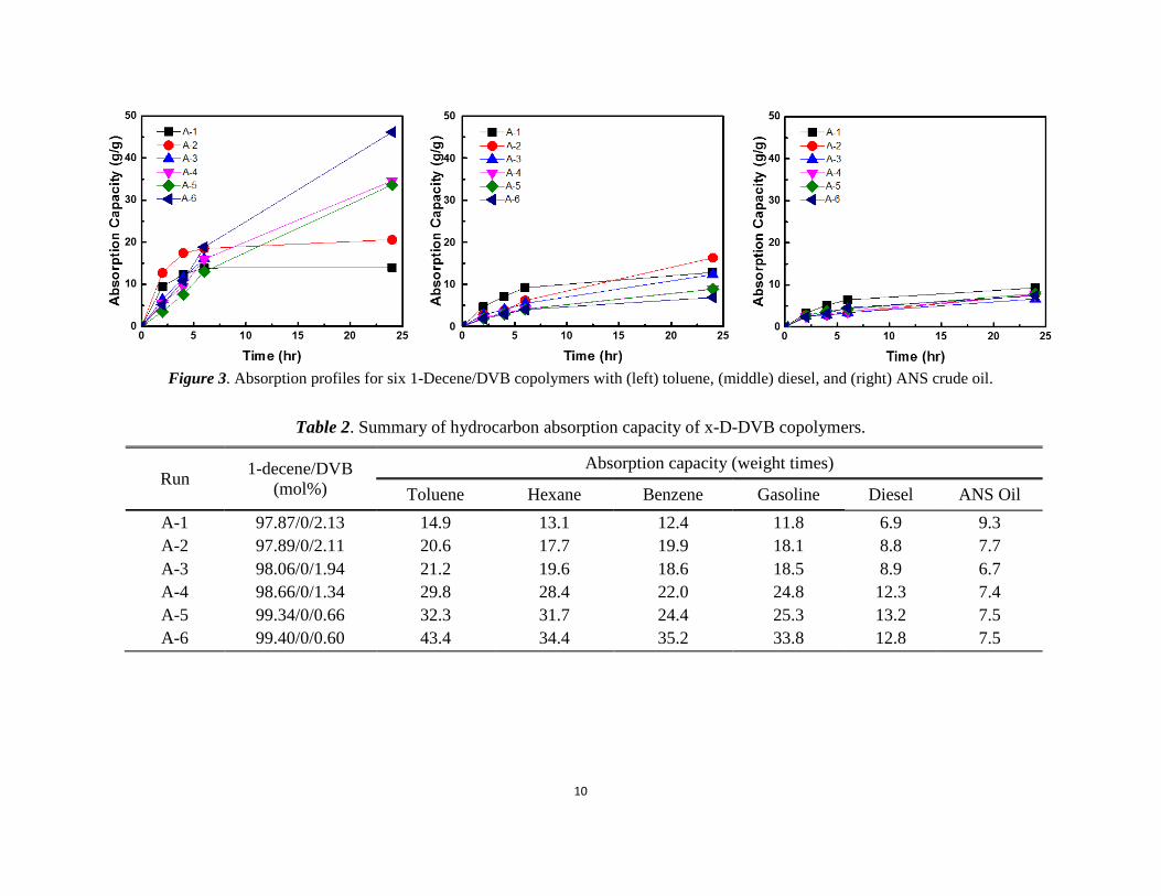
Although there is limited absorption capacity in this semi-crystalline morphology, these LLDPE copolymers (B) are a good sample set for systematically studying the effect of morphology on absorption performance. It is interesting to consider methods to maximize the absorption kinetics and capacity by reducing the diffusion length and increasing the surface area. The same set of LLDPE polymers were processed into films with the film thickness in the range of 200-300 microns by solution-casting method. Figure 5 shows their absorption profiles with toluene, diesel, and ANS crude oil for 24 hours under ambient temperature. They are also following the general trend of toluene>diesel>ANS oil. Comparing the three absorption profiles (Figure 4) for the corresponding pellet forms, all the LLDPE films show significantly fast kinetics, reaching the maximum oil absorption capacity in less than 4 hours. Most of them, with the exception of two densest LLDPE polymers (B-1 and B-2), show significantly higher hydrocarbon absorption capacity than their corresponding pellet forms. Again, the B-6 LLDPE film with the lowest density (0.865 g/cm3) and thickness ~250 µm, shows the highest absorption capacity, about 35 times for toluene, 20 time for diesel, and 10 times for ANS crude oil. In addition, the resulting hydrocarbon-swelled LLDPE films exhibit very good mechanical strength and hydrocarbon (oil) retention, which are suitable for hydrocarbon (oil) storage and recovery applications. Note that a small density difference (0.909 g/cm3 in B-1 vs. 0.865 g/cm3 in B-6) in the LLDPE films has a profound effect on their absorption capacities. In the B-6 film, the combination of high side chain content (9.4 mol%), low crystallinity (12%), and small crystal size (Tm=47 oC) must spontaneously form the continuous channels between the polymer chains, with higher free volume. This low density morphology offers the favorable diffusion path and interaction with hydrocarbon molecules.
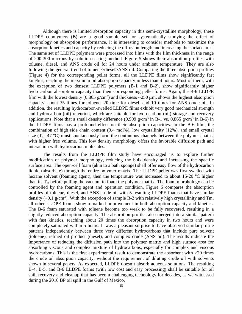
The results from the LLDPE film study have encouraged us to explore further modification of polymer morphology, reducing the bulk density and increasing the specific surface area. The open-cell foam (akin to a bath sponge) shall offer easy flow of the hydrocarbon liquid (absorbate) through the entire polymer matrix. The LLDPE pellet was first swelled with hexane solvent (foaming agent), then the temperature was increased to about 15-20 oC higher than its Tm before pulling the vacuum to foam the polymer matrix. The foam morphology can be controlled by the foaming agent and operation condition. Figure 6 compares the absorption profiles of toluene, diesel, and ANS crude oil with 5 resulting LLDPE foams that have similar density (~0.1 g/cm3). With the exception of sample B-2 with relatively high crystallinity and Tm, all other LLDPE foams show a marked improvement in both absorption capacity and kinetics. The B-6 foam saturated with toluene become too weak to be fully recovered, resulting in a slightly reduced absorption capacity. The absorption profiles also merged into a similar pattern with fast kinetics, reaching about 20 times the absorption capacity in two hours and were completely saturated within 5 hours. It was a pleasant surprise to have observed similar profile patterns independently between three very different hydrocarbons that include pure solvent (toluene), refined oil product (diesel), and complex crude (ANS oil). The results indicate the importance of reducing the diffusion path into the polymer matrix and high surface area for absorbing viscous and complex mixture of hydrocarbons, especially for complex and viscous hydrocarbons. This is the first experimental result to demonstrate the absorbent with >20 times the crude oil absorption capacity, without the requirement of diluting crude oil with solvents shown in several papers. As expected, LLDPE doesn’t absorb aqueous solutions. The resulting B-4, B-5, and B-6 LLDPE foams (with low cost and easy processing) shall be suitable for oil spill recovery and cleanup that has been a challenging technology for decades, as we witnessed during the 2010 BP oil spill in the Gulf of Mexico.
14
Figure 5. Absorption profiles for 6 ethylene/1-octene copolymer films with (left) toluene, (middle) diesel, and (right) ANS crude oil.
Figure 6. Absorption profiles of 5 ethylene/1-octene copolymer foams with (left) toluene, (middle) diesel, and (right) ANS crude oil.
15
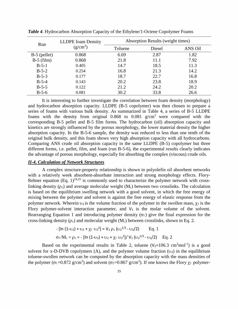
Table 4. Hydrocarbon Absorption Capacity of the Ethylene/1-Octene Copolymer Foams
Run LLDPE foam Density (g/cm3)
Absorption Results (weight times) Toluene Diesel ANS Oil
B-5 (pellet) 0.868 6.69 2.87 1.82 B-5 (film) 0.868 21.8 11.1 7.92
B-5-1 0.405 14.7 18.5 11.3 B-5-2 0.254 16.8 21.3 14.2 B-5-3 0.177 18.7 22.7 16.8 B-5-4 0.143 20.2 23.8 18.9 B-5-5 0.122 21.2 24.2 20.2 B-5-6 0.081 30.2 33.8 26.6
It is interesting to further investigate the correlation between foam density (morphology) and hydrocarbon absorption capacity. LLDPE (B-5 copolymer) was then chosen to prepare a series of foams with various bulk density. As summarized in Table 4, a series of B-5 LLDPE foams with the density from original 0.868 to 0.081 g/cm3 were compared with the corresponding B-5 pellet and B-5 film forms. The hydrocarbon (oil) absorption capacity and kinetics are strongly influenced by the porous morphology, the lower material density the higher absorption capacity. In the B-5-6 sample, the density was reduced to less than one tenth of the original bulk density, and this foam shows very high absorption capacity with all hydrocarbons. Comparing ANS crude oil absorption capacity in the same LLDPE (B-5) copolymer but three different forms, i.e. pellet, film, and foam (run B-5-6), the experimental results clearly indicates the advantage of porous morphology, especially for absorbing the complex (viscous) crude oils.
II-4. Calculation of Network Structures A complex structure-property relationship is shown in polyolefin oil absorbent networks
with a relatively week absorbent-absorbate interaction and strong morphology effects. Flory-Rehner equation (Eq. 1)24,25 is commonly used to characterize the polymer network with cross-linking density (ρc) and average molecular weight (Mc) between two crosslinks. The calculation is based on the equilibrium swelling network with a good solvent, in which the free energy of mixing between the polymer and solvent is against the free energy of elastic response from the polymer network. Wherein υ2 is the volume fraction of the polymer in the swollen mass, χ1 is the Flory polymer-solvent interaction parameter, and V1 is the molar volume of the solvent. Rearranging Equation 1 and introducing polymer density (σ1) give the final expression for the cross-linking density (ρc) and molecular weight (Mc) between crosslinks, shown in Eq. 2.
- [ln (1-υ2) + υ2 + χ1 υ22] = V1 ρc (υ21/3 - υ2/2) Eq. 1
σ1/Mc = ρc = - [ln (1-υ2) + υ2 + χ1 υ22]/ V1 (υ21/3 - υ2/2) Eq. 2
Based on the experimental results in Table 2, toluene (V1=106.3 cm3mol-1) is a good solvent for x-D-DVB copolymers (A), and the polymer volume fraction (υ2) in the equilibrium toluene-swollen network can be computed by the absorption capacity with the mass densities of the polymer (σ1=0.872 g/cm3) and solvent (σ2=0.867 g/cm3). If one knows the Flory χ1 polymer-

16
solvent interaction parameter, the values of ρc and Mc can be determined.26 However, the determination of the χ1 value, including both entropy (χS) and enthalpy (χH) contributions, is far from perfect. For the x-D-DVB/toluene interaction, the χH value is related to the heat of mixing and can be calculated by χΗ = (V1/RT) (δs-δp)2, wherein the solubility parameter of toluene δs= 18.2 Mpa1/2 and solubility parameter of poly(1-decene) δp= 16.6 Mpa1/2.27 However, the χS entropy parameter, associated with the dispersion forces, is a mean semiempirical value 0.34 (with the largest deviation of 0.15) in the nonpolar-nonpolar system. The branched polymer structure usually possesses a considerably lower χS value. In this highly branched D-DVB copolymer structure, we adopted the low end of χS= 0.19 with the calculated χ1 =0.31 that is in consistent with the reported Flory interaction parameter in other polyolefin-toluene systems.28 Table 5 summarizes the estimated ranges of the χ1 parameter using χ1 = χS + (V1/RT) (δs-δp)2 with the range of χS values between 0.19 and 0.34. The cross-linking density (ρc) and average molecular weight (Mc) between two crosslinks are calculated based on the χ1=0.31 value.
Table 5. Calculated ρc and Mc values in the toluene-swollen x-D-DVB networks.
Run υ2 value
χ1 range
ρc (x10-6 mol/cm3) a
Mc (x103 g/mol)a
1-decene units/ crosslinka
A-1 0.0663 0.31-0.46 23.4 12.0
37 264 A-2 0.0460 0.31-0.46 72 514 A-3 0.0447 0.31-0.46 11.4 76 730 A-4 0.0322 0.31-0.46 6.39 136 971 A-5 0.0298 0.31-0.46 5.58 156 1114 A-6 0.0224 0.31-0.46 3.39 256 1828 a. Calculated values by using χ1=0.31 value.
Figure 7. The plots of toluene absorption capacity vs. (top) crosslinking density (ρc) and (bottom) the average molecular weight (Mc) between two crosslinks in the x-D-DVB networks.
The results in Table 5 indicate that only a small fraction of DVB units (35% in A-1 and 18% in A-6) in the D-DVB copolymers involve the inter-chain crosslinking reactions, and the crosslinking efficiency decreases with the decrease of the DVB crosslinker content in the D-DVB copolymer. Figure 7 plots the toluene absorption capacity vs. crosslinking density (ρc) and the average molecular weight (Mc) between crosslinks. The absorption capacity exponentially

17
decreases with the increase of crosslinking density and is linearly increased with the increase of molecular weight (Mc). It is interesting to note the relatively low crosslinking density in most cases, especially for the A-6 sample with an average of only 4 crosslinks per polymer chain and about 1828 repeating 1-decene units between two crosslinks. The combination of high polymer molecular weight and the uniform distribution of the DVB comonomer units is essential in forming this highly swellable (but not soluble) network structure with the lowest crosslinking density possible. The A-6 sample may reach the optimal x-D-DVB network structure that can absorb toluene (good solvent) up to about 43 times its weight at ambient temperature.
It is interesting to extend this network structure calculation to the semicrystalline LLDPE polymer system (B), in which each crystalline domain can serve as a crosslinking point. As discussed, the non-swellable crystalline domains maintain the structure integrity while allowing the amorphous domains to be swollen by a good solvent, such as toluene. The combination of the equilibrium toluene absorption capacity shown in Figure 5 and the density of polymer (σ1) and toluene (σ2=0.867 g/cm3) allows us to determine the υ2 value (volume fraction of the polymer in the swollen mass). With the reported χ1 =0.34 for the LLDPE-toluene interaction parameter, we apply the same Equation 2 to estimate the density of crystalline domains (ρc) and the average molecular weight (Mc) between two crystalline domains in the LLDPE polymers. The results are summarized in Table 6. Figure 8 plots the absorption capacity vs. crystalline domain density (ρc) and the average molecular weight (Mc) between two crystalline domains.
Table 6. Calculated ρc and Mc values in the toluene-swollen LLDPE copolymers.
Run σ1 (g/cm3)
V1
(cm3/mol) υ2
value χ1
value ρc
(x10-6 mol/cm3) Mc
(x103 g/mol) B-1 0.909 106.3 0.67 0.34 4982.7 0.18 B-2 0.897 106.3 0.62 0.34 3759.5 0.24 B-3 0.875 106.3 0.23 0.34 252.8 3.46 B-4 0.870 106.3 0.05 0.34 12.1 71.64 B-5 0.868 106.3 0.04 0.34 8.1 106.87 B-6 0.865 106.3 0.03 0.34 4.8 177.48
Figure 8. The plots of toluene absorption capacity vs. (top) crystalline domain density (ρc) and (bottom) the average molecular weight (Mc) between two crystalline domains in LLDPEs.

18
As expected, the relatively high crystallinity (36%) in the B-1 sample results in high ρc and low Mc values, indicating a tight network structure with low swelling capacity. With the systematical decrease of crystallinity in LLDPE samples, the material becomes softer (expandable) with the reduction of non-swellable domains, and the increase of Mc molecular weight in the amorphous phase. Evidently, the B-6 sample may reach to the structure limit, in which the 12% crystallinity still can provide the absorbent material integrity while allowing toluene swelling in its matrix to the maximum capacity (35 times by wright) at ambient temperature. In fact, both ρc and Mc values approach to similar values in both B-6 and A-6 samples, along with the toluene absorption capacity (35 vs. 43 times). Considering the size and volume fraction of crystalline domains in LLDPE is always larger than the those of DVB crosslinking units in x-D-DVB, it’s logical to expect that the amorphous polymer will always exhibit higher absorption capacity with good solvent under equilibrium condition.
II-5. Oil Absorption Results of i-Petrogel With the combined experimental and calculated results of individual soft and rigid
polyolefin networks, it is possible to construct an i-Petrogel (Scheme 1) with a specific soft/rigid polymer ratio that can exhibit an oil (hydrocarbons) absorption capacity about 40 times if the equilibrium state can be reached. As discussed in Section II-1, the desirable i-Petrogel material has to be processible to form the stable product (powder, flake, film, foam, etc.) with high surface area and short oil diffusion path. Thus, a systematic study was conducted to investigate i-Petrogel structures and their oil absorption capacities and kinetics. The detailed experimental results were reported in previous reports. This final project report only highlights major technological advancements and accomplishments, which is based on the i-Petrogel system with an IPN structure containing D-DVB soft polymer (A) and LLDPE rigid polymer (B).
In a typical i-Petrogel preparation process, a specific weight ratio of D-DVB (A) and LLDPE (B) copolymers were mixed in a homogeneous solution before casting into polymer films. The isolated polymer mixture was subjected to a thermal crosslinking reaction at >200 oC. After cooling down to ambient temperature, the two polymer chains were interpenetrated and connected into a network structure (Scheme 1) through crosslinker (x) units in x-D-DVB and small crystalline domains in LLDPE. The molecule-scale IPN structure offered new i-Petrogel materials with uniform morphology. Additionally, it was easy to fine-tune a complete range of aliphatic/aromatic composition to match the ANS oil composition. It also allowed us to prepare film and foam products with high surface areas and short oil diffusion paths, which have proved to be essential for absorbing ANS crude oil containing a broad range of aliphatic and aromatic hydrocarbons. Overall, our project goal was to achieve rapid ANS oil absorption with high absorption capacity, which can stop spilled oil from "weathering" and provide a temporary oil storage mechanism for positioning the recovery equipment. In addition, the oil-swelled gel (free of water) needed to be easily recovered by skimmers and subsequently refined as regular oils.
Figure 9 compares ANS oil absorption profiles of three i-Petrogel flakes with soft and rigid polymer weight ratios (3/1, 1/1, and 1/3). The ANS oil absorption evaluation was conducted at 25 and 0 oC, respectively, using the ASTM F716-09 test method. All three i-Petrogel absorbents showed remarkably better ANS oil absorption capacities and kinetics than the corresponding individual soft and rigid polyolefin networks. At ambient temperature (Figure 9, left), all three i-

19
Petrogel flakes performed rapid ANS oil absorption kinetics, reaching more than 20 times the polymer weight in less than 2 hours. The i-Petrogel with 1/1 wt. ratio reached 42 times after contacting with ANS oil for 24 hours. Furthermore, it is very interesting to observe the results in Figure 9 (right) when the ANS oil absorption was carried out at 0 oC. The i-Petrogel with 1/1 wt. ratio reached 35 times, and the i-Petrogel with 3/1 wt. ratio reached 45 times the oil absorption capacity. All of them became highly oil-swelled soft gels. It is interesting to note that the differences between the three absorption profiles may be associated with the recovery of the resulting i-Petrogel/ANS oil gel. Some of them, especially the 1/3 sample, after absorbing a large quantity of ANS oil became too soft to fully recover (isolated) from water surface.
Figure 9. ANS oil absorption profiles at 25 oC (left) and 0 oC (right) for three i-Petrogel-0.2 absorbents with 3:1, 1:1, and 1:3 rigid and soft polymer weight ratios, respectively.
Figure 10. ANS oil sorption profiles for (left) #1 PIG melt-brown PP fiber and #2 PIG recycled cellulose and (right) #4 rigid PU foam and #5 flexible PU foam.

20
For comparison, we also evaluated several commercial oil-sorbents under similar sorption conditions at ambient temperature. They represent several material classes, including two most commonly used commercial oil sorbent materials (#1 melt-brown PP and #2 recycled cellulose) purchased from New PIG and two polyurethane foams (#4 rigid PU foam and #5 flexible PU foam) provided by AirTech, a California-based company. Figure 10 shows the ANS oil sorption profiles of these four commercially-available oil sorbents. PIG melt-brown PP fiber pad (#1) showed very fast oil-sorption kinetics with a sorption capacity of about 10 times. This sorption profile is consistent with the adsorption mechanism, i.e. adsorbing oil molecules in its interstices via capillary action. Due to the weak oil-substrate interaction, this PP fiber-based adsorber also exhibited easy re-bleeding of adsorbed oil under a slight external force. PIG recycled cellulose (#2) showed poor oil absorption capacity (2-3 times). As discussed later, it also absorbed a significant quantity of water, causing the recovered solids to be unsuitable for calcinations. On the other hand, both PU foams with open-pore morphology and high surface areas contain both hydrophobic (soft) and hydrophilic (rigid) segments along the polymer chain. Thus, they absorbed both hydrocarbons and some water, and the water absorption capacity was dependent on the length of soft (polyol) segments (discussed later). The fast kinetics of ANS oil
sorption profiles, shown in Figure 10 (right), are consistent with the adsorption mechanism. The rigid PU foam (#4) showed about 12 times the oil adsorption capacity, while the soft (flexible) PU foam (#5) offered a slightly higher oil adsorption capacity, up to 15 times. The difference may be associated with the polyol segment, with the fact that the flexible PU foam has longer soft (hydrocarbon) segments. One key feature of this technology is the reusability of the PU foams. In other words, the adsorbed oil can be removed (recovered) by physical compression, and the recovered PU foams can be repeatedly deployed for many times before discarding as chemical waste.
Figure 11 shows the water-sorption profiles for these commercial oil sorbents. It’s clear that there are two classes of commercial oil-sorbents in terms of water-sorption. Both PP fiber (#1) and EPDM Rubberizer (#3) are prepared from pure hydrocarbon polymers with hydrophobicity to prevent water sorption. On the other hand, the recycled cellulose (#2) and two polyurethane foams (#4 and #5) are quite hydrophilic with significant water-sorption capacity, more than 5 times of the polymer weight.
Figure 11. Water-sorption profiles for commercial sorbents.
21
II-6. Recycling of The Recovered Oil As discussed, a unique feature of i-Petrogel is its ability for recovery and reuse of the
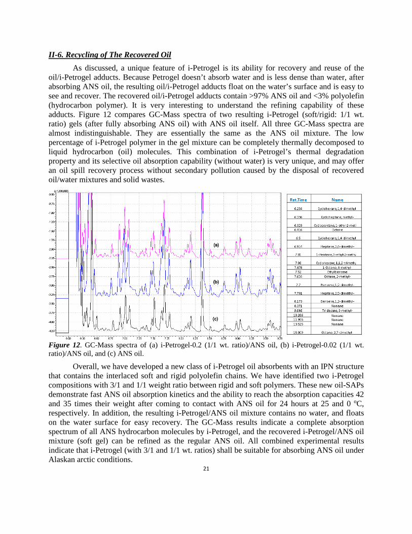
oil/i-Petrogel adducts. Because Petrogel doesn’t absorb water and is less dense than water, after absorbing ANS oil, the resulting oil/i-Petrogel adducts float on the water’s surface and is easy to see and recover. The recovered oil/i-Petrogel adducts contain >97% ANS oil and <3% polyolefin (hydrocarbon polymer). It is very interesting to understand the refining capability of these adducts. Figure 12 compares GC-Mass spectra of two resulting i-Petrogel (soft/rigid: 1/1 wt. ratio) gels (after fully absorbing ANS oil) with ANS oil itself. All three GC-Mass spectra are almost indistinguishable. They are essentially the same as the ANS oil mixture. The low percentage of i-Petrogel polymer in the gel mixture can be completely thermally decomposed to liquid hydrocarbon (oil) molecules. This combination of i-Petrogel’s thermal degradation property and its selective oil absorption capability (without water) is very unique, and may offer an oil spill recovery process without secondary pollution caused by the disposal of recovered oil/water mixtures and solid wastes.
Figure 12. GC-Mass spectra of (a) i-Petrogel-0.2 (1/1 wt. ratio)/ANS oil, (b) i-Petrogel-0.02 (1/1 wt. ratio)/ANS oil, and (c) ANS oil.
Overall, we have developed a new class of i-Petrogel oil absorbents with an IPN structure that contains the interlaced soft and rigid polyolefin chains. We have identified two i-Petrogel compositions with 3/1 and 1/1 weight ratio between rigid and soft polymers. These new oil-SAPs demonstrate fast ANS oil absorption kinetics and the ability to reach the absorption capacities 42 and 35 times their weight after coming to contact with ANS oil for 24 hours at 25 and 0 oC, respectively. In addition, the resulting i-Petrogel/ANS oil mixture contains no water, and floats on the water surface for easy recovery. The GC-Mass results indicate a complete absorption spectrum of all ANS hydrocarbon molecules by i-Petrogel, and the recovered i-Petrogel/ANS oil mixture (soft gel) can be refined as the regular ANS oil. All combined experimental results indicate that i-Petrogel (with 3/1 and 1/1 wt. ratios) shall be suitable for absorbing ANS oil under Alaskan arctic conditions.

22
III. Scale-up i-Petrogel Production A major task in this project was to scale-up the material production for the practical
evaluation of oil spill recovery at the Ohmsett facility. The task focused on two identified i-Petrogel materials with 3/1 and 1/1 weight ratios between rigid and soft copolymers, respectively. In addition to learning the material scale-up process, the main objective was to prepare the required quantity of i-Petrogel absorbents for two evaluations (operational test and simulation test) at the Ohmsett facility. As discussed, the preparation of i-Petrogel material involves two steps, including the first step learning how to scale-up the production of both rigid and soft polyolefin polymers and then investigating the reactive-compounding process to mix two polymers with a specific composition and in situ thermal-crosslinking reaction to form the desired i-Petrogel product with an interpenetrated polymer network (IPN structure).
As shown in Figure 13, we installed a 20-liter autoclave polymerization units (Figure 13a), with several associated control and chemical purification units, and a new 50-liter reactor (Figure 13b) with accessories. The combination provided us the ability to prepare multiple Kg polymer materials in each reaction run and study the scale-up production processes. In the manufacture of 250 lbs i-Petrogel for the simulation test, we also installed several polymer processing equipment, including three polymer film-casting units and a new powerful 4 liters’ lab blender machine for converting i-Petrogel films to i-Petrogel flakes with small flake sizes.
Figure 13. (a) a 20-liter high pressure polymerization system for polymerization reactions and (b) a new 50-liter reactor with control accessories.

23
Table 7. Summary of 1-decene/DVB copolymerization to form various soft D-DVB copolymers. Reaction Conditions Polymerization Results
Run
1-Decene (L)
DVB (L)
Temp/Time (oC/hr.)
1-Decene (mol%)
DVB (mol%)
Yield (%)
A’-1 10 0.5 25/3 97.87 2.13 69 A’-2 10 0.3 25/3 97.90 2.10 90 A’-3 10 0.2 25/3 98.07 1.93 95 A’-4 10 0.05 25/1 99.34 0.66 84 A’-5 10 0.02 25/1 99.57 0.43 92
a Catalyst: TiCl3.AA/Et2AlCl; Solvent: 3 L toluene. b. DVB: divinylbenzene cross-linker.
Table 7 summarizes the TiCl3.AA/Et2AlCl mediated 1-decene/DVB copolymerization using this pilot plant unit. A broad range of high D-DVB copolymers (Mw>330,000 g/mol) with various DVB crosslinker contents were prepared without any detectable crosslinking reaction. The resulting D-DVB copolymer were completely soluble in common organic solvents, such as hexane and toluene. The copolymer structure was confirmed by 1H NMR spectrum. In addition to a chemical shift at 0.8 ppm, corresponding to CH3 in the 1-decene units, and a band between 0.9 and 1.7 ppm, corresponding to CH2 and CH in the polymer backbone, there are three bands around 5.2 and 5.7 ppm (CH=CH2) and 6.7 ppm (CH=CH2); and an aromatic proton band between 6.9 and 7.4 ppm (C6H4). The integrated intensity ratio between all three vinyl protons and the four phenyl protons determine the vinyl/phenyl mole ratio, which is near unity. The experimental results confirmed the mono-enchainment of DVB comonomers in forming the processible D-DVB copolymer. Overall, the experimental results from this pilot-plant unit were consistent with those obtained in the lab-scale reactors (Table 1).
In the subsequent reactive-compounding process to form the desired i-Petrogel material, the resulting D-DVB soft polyolefin polymer was mixed with LLDPE (rigid polyolefin) with a specific weight ratio in toluene solvent. The homogeneous solution was cased into polymer films with a pre-determined thickness, controlled by the volume of solution. After evaporating toluene, the resulting solid films were thermally-cured to form the IPN structure. The resulting i-Petrogel film was tough and not sticky and had the mechanical strength to form stable films, foams, flakes, powders, etc. For the tests at the Ohmsett facility, the cured i-Petrogel films were chopped into flake pieces for easy handling. Several i-Petrogel flakes, with similar rigid/soft copolymer compositions, were tested for their ANS oil absorption capacity and kinetics and compared to results observed in the small scale experiments. Table 8 summarizes two sets of the scaled-up i-Petrogel flakes. In C’ set, the flake samples were prepared by D-DVB copolymer (run A’-3) and the soft/rigid polymer weight ratios of 3/1, 1/1, and 1/3, respectively. In D’ set, the flake samples were formed by D-DVB copolymer (run A’-5) with about 0.5 mol% DVB crosslinkers and the soft/rigid polymer weight ratios of 3/1, 1/1, and 1/3, respectively. Table 8 also shows the ANS oil absorption capacity between two sets of the scaled-up i-Petrogel flakes and the corresponding two x-D-DVB copolymers. All absorption tests were conducted under similar experimental conditions at 25 or 0 oC, following ASTM F716-09 (type II loose absorbent procedure). The absorption capacity was determined by measuring the weight ratio between the absorbed oil after 24 hours to the original dried absorbent.
24
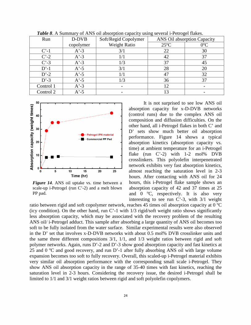
Table 8. A Summary of ANS oil absorption capacity using several i-Petrogel flakes. Run
D-DVB
copolymer Soft/Regid Copolymer
Weight Ratio ANS Oil absorption Capacity
25oC 0oC C’-1 A’-3 3/1 22 30 C’-2 A’-3 1/1 42 37 C’-3 A’-3 1/3 37 45 D’-1 A’-5 3/1 28 20 D’-2 A’-5 1/1 47 32 D’-3 A’-5 1/3 36 37
Control 1 A’-3 - 12 - Control 2 A’-5 - 13 -
It is not surprised to see low ANS oil
absorption capacity for x-D-DVB networks (control runs) due to the complex ANS oil composition and diffusion difficulties. On the other hand, all i-Petrogel flakes in both C’ and D’ sets show much better oil absorption performance. Figure 14 shows a typical absorption kinetics (absorption capacity vs. time) at ambient temperature for an i-Petrogel flake (run C’-2) with 1-2 mol% DVB crosslinkers. This polyolefin interpenetrated network exhibits very fast absorption kinetics, almost reaching the saturation level in 2-3 hours. After contacting with ANS oil for 24 hours, this i-Petrogel flake sample shows an absorption capacity of 42 and 37 times at 25 and 0 oC, respectively. It is also very interesting to see run C’-3, with 3/1 weight
ratio between rigid and soft copolymer network, reaches 45 times oil absorption capacity at 0 oC (icy condition). On the other hand, run C’-1 with 1/3 rigid/soft weight ratio shows significantly less absorption capacity, which may be associated with the recovery problem of the resulting ANS oil/ i-Petrogel adduct. This sample after absorbing a large quantity of ANS oil becomes too soft to be fully isolated from the water surface. Similar experimental results were also observed in the D’ set that involves x-D-DVB networks with about 0.5 mol% DVB crosslinker units and the same three different compositions 3/1, 1/1, and 1/3 weight ratios between rigid and soft polymer networks. Again, runs D’-2 and D’-3 show good absorption capacity and fast kinetics at 25 and 0 oC and good recovery, and run D’-1 after fully absorbing ANS oil with large volume expansion becomes too soft to fully recovery. Overall, this scaled-up i-Petrogel material exhibits very similar oil absorption performance with the corresponding small scale i-Petrogel. They show ANS oil absorption capacity in the range of 35-40 times with fast kinetics, reaching the saturation level in 2-3 hours. Considering the recovery issue, the desired i-Petrogel shall be limited to 1/1 and 3/1 weight ratios between rigid and soft polyolefin copolymers.
Figure 14. ANS oil uptake vs. time between a scale-up i-Petrogel (run C’-2) and a melt blown PP pad.
25
IV. Testing Results from Ohmsett Facility (This Project) IV-1. Operational Test of i-Petrogel at Ohmsett Facility
Between October 5-8, 2015, BSEE conducted an operational test at the Ohmsett facility, involving BSEE Kristi McKinney, Ohmsett team headed by Alan Guarino, and our Penn State team (myself and Dr. Changwoo Nam). This test focused on the operational issues related to oil spill recovery using two scaled-up i-Petrogel absorbents containing 1/1 and 3/1 weight ratio. They are the same i-Petrogel materials (runs C’-2 and C’-3 in Table 8), showing good ANS oil absorption capacities. This operational test was performed in two portable open tanks, containing seawater and the weathered Alaska North Slope (ANS) crude oil, using 20 pounds of i-Petrogel material (10 pounds each). The test focused on oil absorption capacity, recovery of the oil/polymer adducts on water surface by mechanical skimmers, and the ability of the resulting oil/polymer adducts to be pumped into a storage tank. The main objective was to identify the performance of i-Petrogel absorbent and understand the opportunities and barriers for large scale implementation of i-Petrogel technology in an oil spilled site on an open water surface.
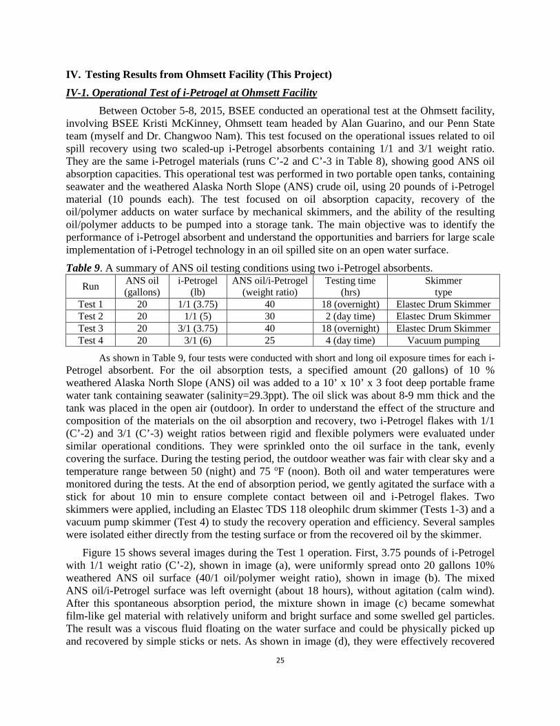
Table 9. A summary of ANS oil testing conditions using two i-Petrogel absorbents.
Run ANS oil (gallons)
i-Petrogel (lb)
ANS oil/i-Petrogel (weight ratio)
Testing time (hrs)
Skimmer type
Test 1 20 1/1 (3.75) 40 18 (overnight) Elastec Drum Skimmer Test 2 20 1/1 (5) 30 2 (day time) Elastec Drum Skimmer Test 3 20 3/1 (3.75) 40 18 (overnight) Elastec Drum Skimmer Test 4 20 3/1 (6) 25 4 (day time) Vacuum pumping
As shown in Table 9, four tests were conducted with short and long oil exposure times for each i-Petrogel absorbent. For the oil absorption tests, a specified amount (20 gallons) of 10 % weathered Alaska North Slope (ANS) oil was added to a 10’ x 10’ x 3 foot deep portable frame water tank containing seawater (salinity=29.3ppt). The oil slick was about 8-9 mm thick and the tank was placed in the open air (outdoor). In order to understand the effect of the structure and composition of the materials on the oil absorption and recovery, two i-Petrogel flakes with 1/1 (C’-2) and 3/1 (C’-3) weight ratios between rigid and flexible polymers were evaluated under similar operational conditions. They were sprinkled onto the oil surface in the tank, evenly covering the surface. During the testing period, the outdoor weather was fair with clear sky and a temperature range between 50 (night) and 75 oF (noon). Both oil and water temperatures were monitored during the tests. At the end of absorption period, we gently agitated the surface with a stick for about 10 min to ensure complete contact between oil and i-Petrogel flakes. Two skimmers were applied, including an Elastec TDS 118 oleophilc drum skimmer (Tests 1-3) and a vacuum pump skimmer (Test 4) to study the recovery operation and efficiency. Several samples were isolated either directly from the testing surface or from the recovered oil by the skimmer.
Figure 15 shows several images during the Test 1 operation. First, 3.75 pounds of i-Petrogel with 1/1 weight ratio (C’-2), shown in image (a), were uniformly spread onto 20 gallons 10% weathered ANS oil surface (40/1 oil/polymer weight ratio), shown in image (b). The mixed ANS oil/i-Petrogel surface was left overnight (about 18 hours), without agitation (calm wind). After this spontaneous absorption period, the mixture shown in image (c) became somewhat film-like gel material with relatively uniform and bright surface and some swelled gel particles. The result was a viscous fluid floating on the water surface and could be physically picked up and recovered by simple sticks or nets. As shown in image (d), they were effectively recovered

26
by an Elastec TDS 118 oleophilc drum skimmer which was tested at various drum rotational speeds. Although a higher drum rotation speed (>20 rpms) increased the recovery rate, it also picked up some water droplets along with the recovered ANS oil/i-Petrogel fluid as shown in image (e). It is interesting to note that the viscous ANS oil/i-Petrogel fluid exhibited good adhesion to the HDPE drum surface and also provided a continuous oil/i-Petrogel fluid flow toward the rotating drums during the recovery. As shown in image (f), the recovered ANS oil/i-Petrogel fluid could also be pumped using a metered pump pallet.
Figure 15. (a) The scaled-up i-Petrogel flakes with 1/1 weight ratio, (b) after spreading i-Petrogel flakes onto the oil surface, (c) after 18 hours absorption time, (d) recovery of ANS oil/i-Petrogel fluid by an Elastec TDS 118 oleophilc drum skimmer, (e) the recovered ANS oil/i-Petrogel fluid with high drum rotation speed, and (f) pumping of the recovered ANS oil/i-Petrogel fluid.

27
Figure 16 shows two images during Test 3 that was carried out under similar operation as in Test 1 except using the i-Petrogel with 3/1 weight ratio (C’-3). The same 3.75 pounds of i-Petrogel with 3/1 weight ratio was spread onto 20 gallons 10% weathered ANS oil surface (40/1 oil/polymer weight ratio), and the mixture was left overnight under similar weather condition. Image (a) shows the ANS oil/i-Petrogel surface after 18 hours spontaneous oil absorption. The resulting ANS oil/i-Petrogel adduct formed a cohesive (sheet-like) gel that could be easily picked up and recovered by simple sticks or nets, as sown in image (b). However, the recovery by an Elastec TDS 118 oleophilc drum skimmer required some physical assistance to move the sheet-like ANS oil/i-Petrogel adduct toward the rotating drums. In addition, the recovered viscous adduct also showed some pumping difficulties using the metered pump pallet. Some modification in skimmer and pump may be needed to recover and pump this material.
Figure 16. (a) The sheet-like ANS oil/i-Petrogel (3/1) adduct, (b) recovery of ANS oil/i-Petrogel sheet by a simple stick.
Figure 17. The recovered ANS oil/i-Petrogel samples from (a) the testing surface of Test 1 (18 h), (b) the drum skimmer recovered oil of Test 1 (18 h), (c) the drum skimmer recovered oil of Test 2 (2 h), (d) the testing surface of Test 3 (18 h), (e) the drum skimmer recovered oil of Test 3 (18 h), and (f) the vacuum pump recovered oil of Test 4 (4 h).
Figure 17 shows one set of the recovered ANS oil/i-Petrogel samples from this operational test. The first half (samples a, b, and c) shows i-Petrogel with 1/1 weight ratio, and the second half (samples d, e, and f) shows i-Petrogel with 3/1 weight ratio. Sample (a) was directly picked up from the testing surface in Test 1 (after 18 h absorption), and sample (b) was the same ANS oil/i-Petrogel fluid recovered by the drum skimmer. Sample (c) was the drum skimmer recovered ANS oil/i-Petrogel fluid after 2 hours testing in Test 2. Samples (d) and (e)

28
were the recovered sheet-like ANS oil/i-Petrogel adducts in Test 3 (18 h) by directly picked out or by the drum skimmer, respectively. Sample (f) was the vacuum pump recovered ANS oil/i-Petrogel adduct of Test 4 (4 h).
Water content in the recovered samples was determined by two methods, including the phase-separated water and TGA-Mass measurements. The trapped water was slowly phase-separated from the recovered ANS oil/i-Petrogel fluids. They are clearly observed in the bottom of sample (b) and sample (f) bottles. We usually sampled the top layer of ANS oil/i-Petrogel fluids for all the measurements. The first experiment was conducted by diluting the recovered ANS oil/i-Petrogel sample with dry toluene to reduce the material viscosity. The mixed solution was then placed in a burette for 24 hours to separate the trapped water and remove the contaminated water at the bottom of the burette. Table 10 summarizes the water contents in all samples after setting for 2 days and 2 months, respectively. The water contents in samples (a) and (b) were very low (<0.1 wt%). Other samples have significantly higher water contents, which is associated with the speed of drum rotation, the viscosity of ANS oil/i-Petrogel fluid, and the setting time. Samples (d), (e), and (f), using i-Petrogel with 3/1 weight ratio, trapped more water during the recovery and were also more difficult in the phase separation, which may be associated with their high fluid viscosity.
Figure 18. TGA-MASS results during the pyrolysis of the recovered sample b.
The recovered sample (b) was also examined by TGA-MS with a heating rate of 10 oC/min from 50 to 600 oC. In addition to measuring the weight loss of the recovered sample by TGA, the resulting pyrolyzed products (H2O, CO, and CO2) were also monitored by a Mass spectrometer. As shown in Figure 18, sample (b) completely decomposed upon heating, with no detectable water during the pyrolysis. Most of the evolution gas is CO gas.
IV-2. Simulation Test of i-Petrogel at Ohmsett Facility Between December 19-22, 2016, BSEE conducted a field simulation test in the Ohmsett
main tank to study ANS oil spill recovery using the i-Petrogel (flake form) absorbent. The test involved the same team, including BSEE Kristi McKinney, Ohmsett team headed by Alan Guarino, and our Penn State team (myself and Dr. Changwoo Nam). Several specific tests were
Sample
Water Content (weight%)
after 2 days
After 2 months
a 0.01 0 b 0.1 0.07 c 2.8 1.2 d 4.6 2.8 e 4.4 3 f 7.4 4.5
Table 10. Water contents in the recovered samples.

29
designed to assess (a) i-Petrogel’s ability to contain the spreading of surface oil in calm and gentle wave conditions and (b) the ability of an oleophilic skimmer to collect the i-Petrogel absorbed oil adducts after their exposure to air and on sea water surface for few days. In addition, we also examined the recovered oil/i-Petrogel adducts (with and without water) to understand water content in the recovered oil, the quality of water after the oil removal, and the evaporation and re-bleeding of the i-Petrogel absorbed oil. The ideal oil absorbent shall stop the weathering (i.e. spreading, emulsification, dispersion, and evaporation) of the spilled oil within the initial hours. The water shall be clean (completely free of hydrocarbons), and the recovered oil (with i-Petrogel) shall be reused without causing secondary pollution.
Table 11. Experimental conditions in the simulation tests. Test No.
Oil/Petrogel (wt. ratio)
Contact place
Contact Time (h)
Experimental details
1 Pre-test to adjust the camera tracking system on spreading oil. 2 cold oil 2-gallon cold ANS oil was freely released to see its spreading behavior on seawater. 3 30/1 O-ring 1/6 (cold) i-Petrogel flakes was sprinkled on the spilled oil inside the O-ring. 4 30/1 O-ring 1 (cold) i-Petrogel flakes was sprinkled on the spilled oil inside the o-ring. 5 30/1 O-ring 1 (cold) i-Petrogel flakes was distributed on the spilled oil inside the o-ring. 6 30/1 O-ring 16 (cold) i-Petrogel flakes was distributed on the spilled oil inside the o-ring. 7 warm oil 2 gallon warm ANS oil was freely released to see its spreading behavior on seawater. 8 30/1 Bucket 1 (warm) i-Petrogel was pre-mixed (warm) before releasing on seawater. 9 30/1 Bucket 1 (cold) i-Petrogel was pre-mixed (cold) before releasing on seawater. 10 20/1 Bucket 1 (warm) i-Petrogel was pre-mixed (warm) before releasing on seawater. 11 20/1 Bucket 2 (warm) i-Petrogel was pre-mixed (warm) before releasing on seawater. 12 20/1 Bucket 1 (cold) i-Petrogel was pre-mixed (cold) before releasing on seawater. 13 30/1 Bucket 2 cold) i-Petrogel was pre-mixed (cold) before releasing on seawater. 14 20/1 Bucket 2 (cold) i-Petrogel was pre-mixed (cold) before releasing on seawater. 15 Dispensing test using a blower to distribute i-Petrogel flakes to 2 gallon ANS oil on water surface. 16 Skimming test using a drum skimmer to correct all the ANS oil with i-Petrogel (tests 2-15) in main tank. a. Testing schedule: Test 1 (12/19, afternoon); Tests 2-5 (12/20); Tests 6-10 (12/21), and Test 11-15 (12/22). b. 30/1 wt. ratio: 2 gallons of ANS oil and 0.486 lbs of i-Petrogel. c. 20/1 wt. ratio: 2 gallons of ANS oil and 0.729 lbs of i-Petrogel. d. Warm: 58-62 oF (indoor); Cold: 44-46 oF (outdoor).
Two control runs (Tests 2 and 7) were conducted to understand ANS oil spreading behavior on water surface. We used both outdoor (cold) and indoor (warm) conditioned ANS oil, respectively. In Tests 3-6, a rubber-made O-ring (Figure 19) was applied to contain 2 gallons
(~14 lbs) of fresh ANS oil on water, before sprinkling i-Petrogel flakes (0.486 lbs) onto the top of oil surface, which corresponds to 30/1 oil/i-Petrogel weight ratio. The oil absorption took place in the O-ring for a specific time (i.e. 10 minutes for Test 3, 1 hour for Tests 4 and 5, and overnight for Test 6). In Tests 5 and 6, a stick was also used to distribute the sprinkled i-Petrogel flakes to improve their contact with the oil. After the allotted time passed, the O-ring was removed, and the oil/i-Petrogel adduct was allowed to spread out with the increasing surface area of Figure 19. A O-ring for containing oil.
30
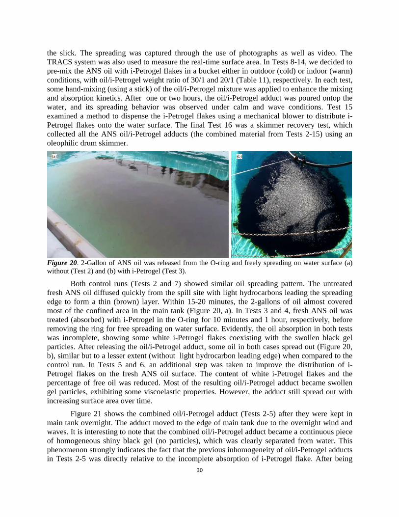
the slick. The spreading was captured through the use of photographs as well as video. The TRACS system was also used to measure the real-time surface area. In Tests 8-14, we decided to pre-mix the ANS oil with i-Petrogel flakes in a bucket either in outdoor (cold) or indoor (warm) conditions, with oil/i-Petrogel weight ratio of 30/1 and 20/1 (Table 11), respectively. In each test, some hand-mixing (using a stick) of the oil/i-Petrogel mixture was applied to enhance the mixing and absorption kinetics. After one or two hours, the oil/i-Petrogel adduct was poured ontop the water, and its spreading behavior was observed under calm and wave conditions. Test 15 examined a method to dispense the i-Petrogel flakes using a mechanical blower to distribute i-Petrogel flakes onto the water surface. The final Test 16 was a skimmer recovery test, which collected all the ANS oil/i-Petrogel adducts (the combined material from Tests 2-15) using an oleophilic drum skimmer.
Figure 20. 2-Gallon of ANS oil was released from the O-ring and freely spreading on water surface (a) without (Test 2) and (b) with i-Petrogel (Test 3).
Both control runs (Tests 2 and 7) showed similar oil spreading pattern. The untreated fresh ANS oil diffused quickly from the spill site with light hydrocarbons leading the spreading edge to form a thin (brown) layer. Within 15-20 minutes, the 2-gallons of oil almost covered most of the confined area in the main tank (Figure 20, a). In Tests 3 and 4, fresh ANS oil was treated (absorbed) with i-Petrogel in the O-ring for 10 minutes and 1 hour, respectively, before removing the ring for free spreading on water surface. Evidently, the oil absorption in both tests was incomplete, showing some white i-Petrogel flakes coexisting with the swollen black gel particles. After releasing the oil/i-Petrogel adduct, some oil in both cases spread out (Figure 20, b), similar but to a lesser extent (without light hydrocarbon leading edge) when compared to the control run. In Tests 5 and 6, an additional step was taken to improve the distribution of i-Petrogel flakes on the fresh ANS oil surface. The content of white i-Petrogel flakes and the percentage of free oil was reduced. Most of the resulting oil/i-Petrogel adduct became swollen gel particles, exhibiting some viscoelastic properties. However, the adduct still spread out with increasing surface area over time.
Figure 21 shows the combined oil/i-Petrogel adduct (Tests 2-5) after they were kept in main tank overnight. The adduct moved to the edge of main tank due to the overnight wind and waves. It is interesting to note that the combined oil/i-Petrogel adduct became a continuous piece of homogeneous shiny black gel (no particles), which was clearly separated from water. This phenomenon strongly indicates the fact that the previous inhomogeneity of oil/i-Petrogel adducts in Tests 2-5 was directly relative to the incomplete absorption of i-Petrogel flake. After being

31
saturating with ANS oil, the i-Petrogel changed from individual flakes to a uniform continuous gel. Due to the larger size of current i-Petrogel flake, the self-diffusion of ANS oil into i-Petrogel matrix takes more time to achieve the saturation level. In other words, the absorption process requires longer time to capture all the spilled oil, and wind and waves from nature shall help the mixing process and shorten the absorption time. As will be discussed later, this homogeneous shiny black soft gel, with suitable viscoelastic properties, can be effectively collected by an oleophilic drum-skimmer (the same as that observed during the operational test).
Figure 21. The combined oil/i-Petrogel adducts (Tests 2-5) after staying in the tank for overnight.
With the observation in Tests 2-7, we decided to pre-mix ANS oil with i-Petrogel flakes before releasing the mixture onto water in the subsequent Tests 8-14. The pre-mixing process was conducted in a basket by hand-stirring and agitating the oil/i-Petrogel mixture in either indoor or outdoor, with 20/1 and 30/1 oil/i-Petrogel weight ratios (Table 11), respectively. Overall, the mixing temperature seemed to have no notable effect to homogeneity of the mixture. However, the constant stirring and agitation were important to achieving a homogeneous oil/i-Petrogel adduct (i.e. shiny black and uniform soft gel). Figure 22 shows an oil/i-Petrogel (20/1) adduct (Test 11) after hand-mixing with intervals in cold environment for 2 hours and releasing it onto water surface, with and without waves. Figure 22 (a) shows the adduct in calm water condition. There was no visible white i-Petrogel material or particles. The oil/i-Petrogel adduct (viscous black gel) formed a clear boundary (sharp edge) to water, indicating no free oil. With waves, the soft gel was moved and stretched along the wave direction, shown in Figure 22 (b). However, there was no observable re-bleaching of hydrocarbons from the soft gel. The sharp edge at the water/gel boundary was remained even the gel was eventually broken apart by strong breaking waves. Basically, the resulting oil/i-Petrogel adduct maintained its oil absorption power on the water surface.

32
Figure 22. The oil/i-Petrogel adduct on water surface (a) without and (b) with waves in Test 11.
For simulating the operational condition, we also examined a new dispensing method using a mechanical blower to apply i-Petrogel flakes onto the specific oil covered area. As shown in Figure 23, a common commercial blower was effective and efficient in distributing i-Petrogel flakes to the specific area. With some engineering design, it shall not be a major issue to apply a large quantity of i-Petrogel flakes or powders to a wide open and remorse oil spilled area using airplanes or helicopters for achieving fast responses.
Figure 23. Dispensing i-Petrogel flakes onto water surface by a blower (Test 15).
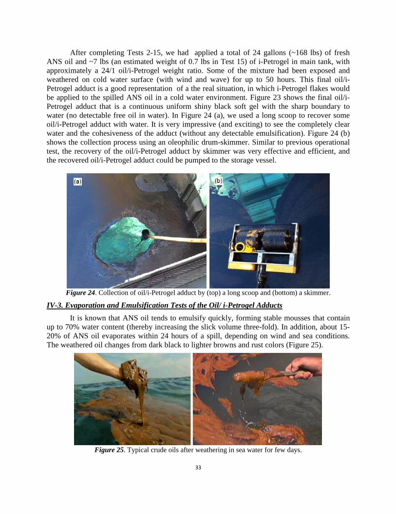
33
After completing Tests 2-15, we had applied a total of 24 gallons (~168 lbs) of fresh ANS oil and ~7 lbs (an estimated weight of 0.7 lbs in Test 15) of i-Petrogel in main tank, with approximately a 24/1 oil/i-Petrogel weight ratio. Some of the mixture had been exposed and weathered on cold water surface (with wind and wave) for up to 50 hours. This final oil/i-Petrogel adduct is a good representation of a the real situation, in which i-Petrogel flakes would be applied to the spilled ANS oil in a cold water environment. Figure 23 shows the final oil/i-Petrogel adduct that is a continuous uniform shiny black soft gel with the sharp boundary to water (no detectable free oil in water). In Figure 24 (a), we used a long scoop to recover some oil/i-Petrogel adduct with water. It is very impressive (and exciting) to see the completely clear water and the cohesiveness of the adduct (without any detectable emulsification). Figure 24 (b) shows the collection process using an oleophilic drum-skimmer. Similar to previous operational test, the recovery of the oil/i-Petrogel adduct by skimmer was very effective and efficient, and the recovered oil/i-Petrogel adduct could be pumped to the storage vessel.
Figure 24. Collection of oil/i-Petrogel adduct by (top) a long scoop and (bottom) a skimmer.
IV-3. Evaporation and Emulsification Tests of the Oil/ i-Petrogel Adducts It is known that ANS oil tends to emulsify quickly, forming stable mousses that contain
up to 70% water content (thereby increasing the slick volume three-fold). In addition, about 15-20% of ANS oil evaporates within 24 hours of a spill, depending on wind and sea conditions. The weathered oil changes from dark black to lighter browns and rust colors (Figure 25).
Figure 25. Typical crude oils after weathering in sea water for few days.
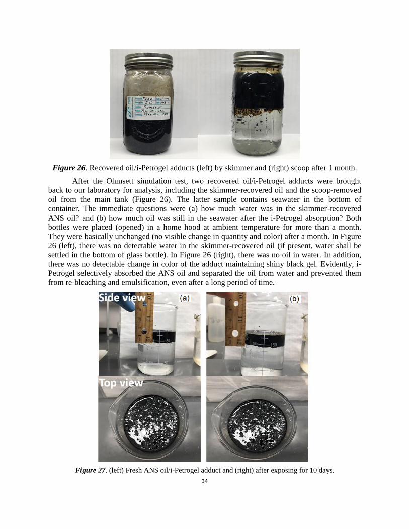
34
Figure 26. Recovered oil/i-Petrogel adducts (left) by skimmer and (right) scoop after 1 month.
After the Ohmsett simulation test, two recovered oil/i-Petrogel adducts were brought back to our laboratory for analysis, including the skimmer-recovered oil and the scoop-removed oil from the main tank (Figure 26). The latter sample contains seawater in the bottom of container. The immediate questions were (a) how much water was in the skimmer-recovered ANS oil? and (b) how much oil was still in the seawater after the i-Petrogel absorption? Both bottles were placed (opened) in a home hood at ambient temperature for more than a month. They were basically unchanged (no visible change in quantity and color) after a month. In Figure 26 (left), there was no detectable water in the skimmer-recovered oil (if present, water shall be settled in the bottom of glass bottle). In Figure 26 (right), there was no oil in water. In addition, there was no detectable change in color of the adduct maintaining shiny black gel. Evidently, i-Petrogel selectively absorbed the ANS oil and separated the oil from water and prevented them from re-bleaching and emulsification, even after a long period of time.
Figure 27. (left) Fresh ANS oil/i-Petrogel adduct and (right) after exposing for 10 days.

35
It is very interesting to examine the evaporation property of ANS oil in oil/i-Petrogel adduct. As discussed, ANS oil losses 15-20 % weight through evaporation in 24 hours in ambient temperature condition. As shown in Figure 27, we conducted a test using the same i-Petrogel flake (1.2 g) with fresh ANS oil (36 g) on seawater surface, the same 30/1 oil/i-Petrogel weight ratio. The solution was exposed to a flow of air in a fume hood at ambient temperature. After 10 days, the total weight (including ANS oil, i-Petrogel, water, and beaker) changed from 291 g to 289 g. Assuming the 2 g weight loss is all from ANS oil, the weight loss of ANS oil is 5 % after 10 days’ exposure, which is dramatically smaller than that of ANS oil evaporation under similar condition. Evidently, ANS oil absorbed in i-Petrogel almost stops its weathering process, and i-Petrogel provides a shelter (temporary storage) for the spilled ANS oil.
V. Conclusion A systematic study has been conducted in the Penn State research laboratory and at the
Ohmsett testing facility to develop and understand a new class of i-Petrogel oil absorbents that can provide a practical solution for the ANS oil spill recovery in Alaskan Arctic seawater conditions. The new i-Petrogel with an IPN structure is formed by two interlaced polyolefin chains between a soft (low Tg) amorphous polyolefin elastomer and a rigid semicrystalline polyolefin thermoplastic. This IPN network cannot be separated unless chemical bonds are broken. In this study, we have answered several key questions and issues related to the practical application of i-Petrogel in major oil spills, including the absorption capacity and kinetics, the prevention of spilled oil from weathering (evaporation, emulsification, spreading, etc.), the recovery and transport of the absorbed oil, and the reuse of the recovered oil. In addition, we have also developed the large-scale and economic material production process. Generally, the experimental results obtained in Penn State laboratory are consistent with the testing results at the Ohmsett facility. Based on observations, we can draw several conclusion, discussed below:
• i-Petrogel material: We have identified the most suitable i-Petrogel IPN structure that can effectively and efficiently recover the spilled ANS oil on the seawater surfaces. The material scale-up process, including polymer preparation and processing into various forms, has been developed for mass production of various i-Petrogel products.
• ANS oil absorption capacity and kinetics: i-Petrogel is capable of absorbing ANS oil 35-40 times the capacity at 25 and 0 oC, and the absorption kinetics are strongly dependent on the oil diffusion path in the i-Petrogel, shorter is better. Some small flake i-Petrogel products exhibited fast ANS oil absorption in the first 2-3 hours to reach 80-90% saturation. The i-Petrogel with 1/1 rigid/soft polymer weight ratio absorbs slightly more ANS oil to form viscous ANS oil/i-Petrogel fluid. On the other hand, the i-Petrogel with 3/1 rigid/soft polymer weight ratio forms the sheet-like ANS oil/i-Petrogel adduct.
• Recovery by skimmers and pumping ability: The Elastec TDS 118 oleophilic (HDPE) drum skimmer (with smooth drum surface) showed effective recovery of ANS oil/i-Petrogel viscous fluids, involving the i-Petrogel with 1/1 rigid/soft polymer weight ratio. The recovered oil/i-Petrogel fluid can be effectively pumped using the metered pump pallet from the skimmer sump to the storage tank.
• Water content in the recovered ANS Oil/i-Petrogel adducts: The water content in the recovered sample is associated with the viscosity of ANS oil/i-Petrogel fluid, the speed of skimmer drum rotation, and the sample setting time to allow water phase separation. Using i-Petrogel (1/1 weight ratio) absorbent, the water content is almost negligible.
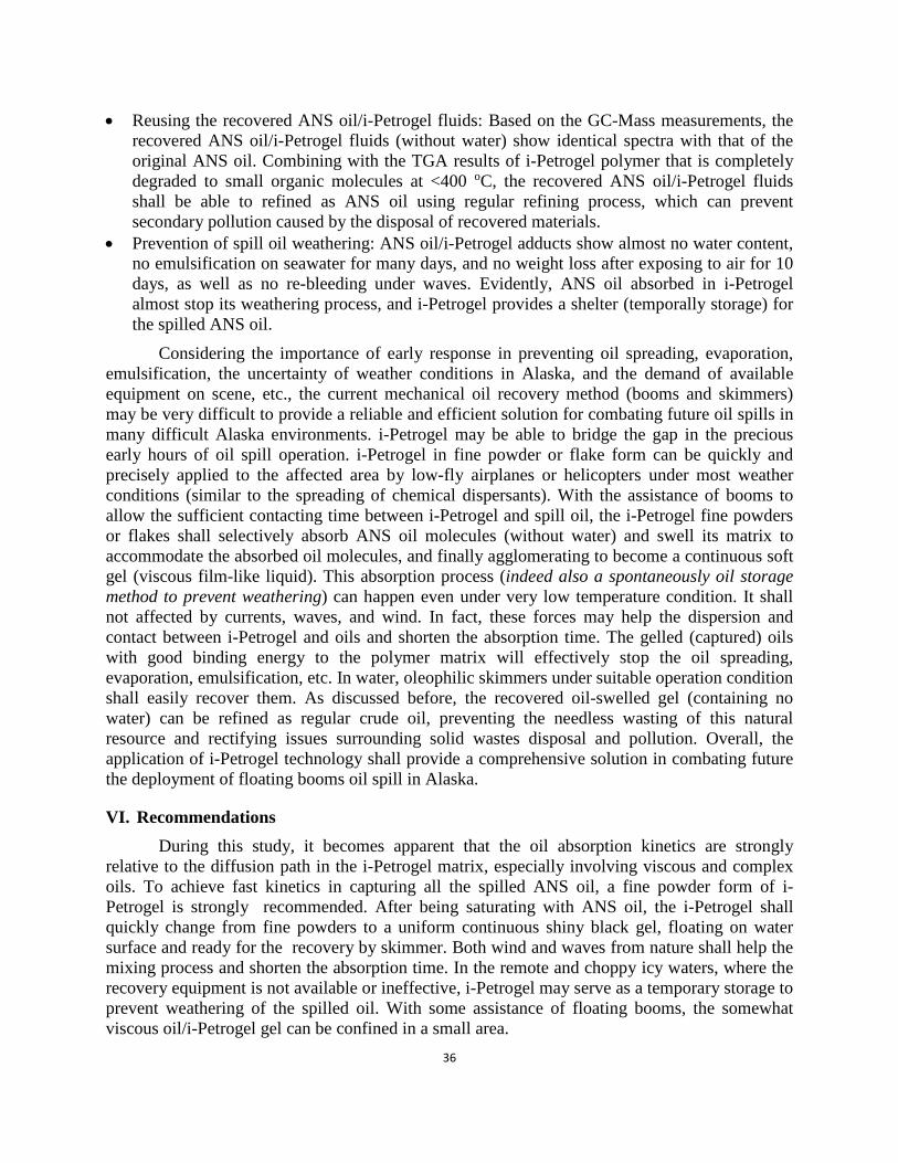
36
• Reusing the recovered ANS oil/i-Petrogel fluids: Based on the GC-Mass measurements, the recovered ANS oil/i-Petrogel fluids (without water) show identical spectra with that of the original ANS oil. Combining with the TGA results of i-Petrogel polymer that is completely degraded to small organic molecules at <400 oC, the recovered ANS oil/i-Petrogel fluids shall be able to refined as ANS oil using regular refining process, which can prevent secondary pollution caused by the disposal of recovered materials.
• Prevention of spill oil weathering: ANS oil/i-Petrogel adducts show almost no water content, no emulsification on seawater for many days, and no weight loss after exposing to air for 10 days, as well as no re-bleeding under waves. Evidently, ANS oil absorbed in i-Petrogel almost stop its weathering process, and i-Petrogel provides a shelter (temporally storage) for the spilled ANS oil.
Considering the importance of early response in preventing oil spreading, evaporation, emulsification, the uncertainty of weather conditions in Alaska, and the demand of available equipment on scene, etc., the current mechanical oil recovery method (booms and skimmers) may be very difficult to provide a reliable and efficient solution for combating future oil spills in many difficult Alaska environments. i-Petrogel may be able to bridge the gap in the precious early hours of oil spill operation. i-Petrogel in fine powder or flake form can be quickly and precisely applied to the affected area by low-fly airplanes or helicopters under most weather conditions (similar to the spreading of chemical dispersants). With the assistance of booms to allow the sufficient contacting time between i-Petrogel and spill oil, the i-Petrogel fine powders or flakes shall selectively absorb ANS oil molecules (without water) and swell its matrix to accommodate the absorbed oil molecules, and finally agglomerating to become a continuous soft gel (viscous film-like liquid). This absorption process (indeed also a spontaneously oil storage method to prevent weathering) can happen even under very low temperature condition. It shall not affected by currents, waves, and wind. In fact, these forces may help the dispersion and contact between i-Petrogel and oils and shorten the absorption time. The gelled (captured) oils with good binding energy to the polymer matrix will effectively stop the oil spreading, evaporation, emulsification, etc. In water, oleophilic skimmers under suitable operation condition shall easily recover them. As discussed before, the recovered oil-swelled gel (containing no water) can be refined as regular crude oil, preventing the needless wasting of this natural resource and rectifying issues surrounding solid wastes disposal and pollution. Overall, the application of i-Petrogel technology shall provide a comprehensive solution in combating future the deployment of floating booms oil spill in Alaska.
VI. Recommendations During this study, it becomes apparent that the oil absorption kinetics are strongly
relative to the diffusion path in the i-Petrogel matrix, especially involving viscous and complex oils. To achieve fast kinetics in capturing all the spilled ANS oil, a fine powder form of i-Petrogel is strongly recommended. After being saturating with ANS oil, the i-Petrogel shall quickly change from fine powders to a uniform continuous shiny black gel, floating on water surface and ready for the recovery by skimmer. Both wind and waves from nature shall help the mixing process and shorten the absorption time. In the remote and choppy icy waters, where the recovery equipment is not available or ineffective, i-Petrogel may serve as a temporary storage to prevent weathering of the spilled oil. With some assistance of floating booms, the somewhat viscous oil/i-Petrogel gel can be confined in a small area.
37
VII. References (1) Graham, L. J.; Hale, C.; Maung-Douglass, E.; Sempier, S.; Swann, L.; Wilson, M.
"Chemical dsipersants and their roles in oil spill response", http://masgc.org/oilscience/oil-spill-science-dispersant-bkgrnd.pdf
(2) Gwen Ifill, "What happens to debris from gulf oil cleanup?" http://www.pbs.org/newshour/bb/environment-july-dec10-oil_08-11/
(3) Phaedra Ellis-Lamkins, "BP's Gulf oil waste being dumped on communities of color", http://grist.org/article/from-oil-spill-to-oil-dump-the-dirty-secret-of-bps-clean-up/
(4) Chol, H. M.; Cloud, R. M. Environ. Sci. Technol. 1992, 26, 772–776 (5) Teas, C.; Kalligeros, S.; Zanikos, F.; Stournas, S.; Lois, E.; Anastopoulos, G. Desalination
2001, 140, 259– 264 (6) Inagaki, M.; Kawahara, A.; Konno, H. Carbon 2002, 40, 105–111 (7) Adebajo, M. O.; Frost, R. L.; Kloprogge, J. T.; Carmody, O.; Kokot, S. J. Porous Mater.
2003, 10, 159–170 (8) Deschamps, G.; Caruel, H.; Borredon, M. E.; Bonnin, C.; Vignoles, C. Environ. Sci.
Technol. 2003, 37, 1013–1015 (9) Suni, S.; Kosunen, A. L.; Hautala, M.; Pasila, A.; Romantschuk, M. Mar. Pollut. Bull.
2004, 49, 916–921 (10) Sun, X. F.; Sun, R. C.; Sun, J. X. J. Mater. Sci. 2003, 38, 3915–3923 (11) Arbatan, T.; Fang, X.; Shen, W. Chem. Eng. J. 2011, 166, 787–791 (12) Karakasi, O. K.; Moutsatsou, A. Fuel 2010, 89, 3963–3970 (13) Bayat, A.; Aghamiri, S. F.; Moheb, A.; Vakili-Nezhaad, G. R. Chem. Eng. Technol. 2005,
28, 1525–1528 (14) Wei, Q. F.; Mather, R. R.; Fotheringham, A. F.; Yang, R. D. Mar. Pollut. Bull. 2003, 46,
780–783 (15) Yuan, X.; Chung, T. C. Energy & Fuels 2012, 26, 4896–4902 (16) Chung, T. C. Macromolecules 2013, 46, 6671–6698 (17) Chung, T. C. Yuan, X. U. S. Patent 9,109,057 (2015) (18) Dragan, E. S. Chem. Eng. J. 2014, 243, 572-590 (19) Waters, D. J.; Engberg, K.; Parke-Houbent, R. P.; Ta, C. N.; Jackson, A. J.; Toney, M. F.;
Frank, C. W. Macromolecules 2011, 44, 5776 (20) Owens III, D. E.; Jian, Y.; Fang, J. E.; Slaughter, B. V.; Chen, Y.; Peppas, N. A.
Macromolecules 2007, 40, 7306-7310 (21) Xia, X.; Hu, Z. Langmuir 2004, 20, 2094-2098 (22) Nam, C.W.; Li, H.; Zhang, G.; Chung, T. C. Macromolecules 2016, 49, 5427-5437 (23) Lin, W.; Shao, Z.; Dong, J.; Chung, T. C. Macromolecules 2009, 42, 3750–3754 (24) Sperling, L. H. Introduction to Physical Polymer Science; John Wiley & Sons, Inc., 2005;
pp 1–28 (25) Alberda van Ekenstein, G. O. R.; Meyboom, R.; ten Brinke, G.; Ikkala, O. Macromolecules
2000, 33, 3752–3756 (26) Neuburger, N. A.; Eichinger, B. E. Macromolecules 1988, 21, 3060–3070 (27) Hansen, C. In Hansen Solubility Parameters; CRC Press, 2007; pp 293–310 (28) Milner, S. T.; Lacasse, M.-D.; Graessley, W. W. Macromolecules 2009, 42, 876–886